

Page 1
Page 2
Page 3
Page 4
Page 5
Page 6
6
10/02
SPARES
LIST
2900/2950
ITEM CAT NO. WATTS VOLTS DESCRIPTION COLOUR MODEL
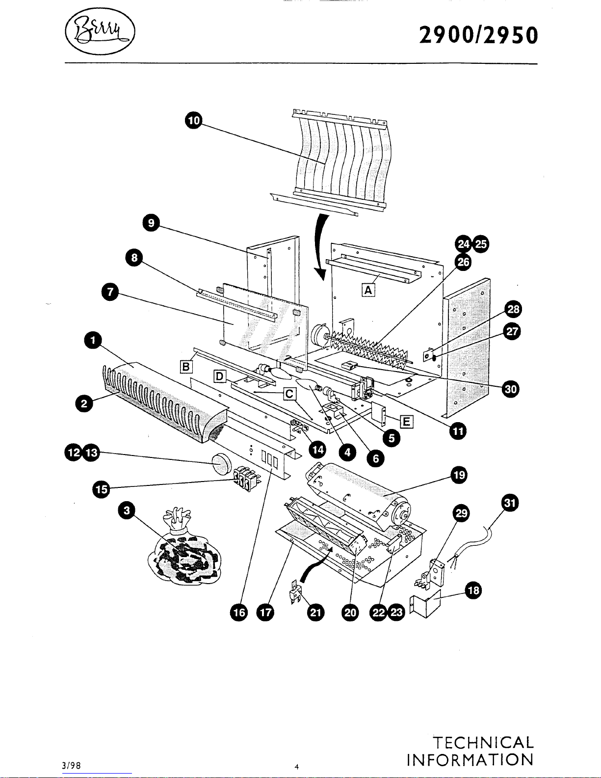
1, 2 FP9811 Fuel Effect Bed Assembly
3 FP9650 Coal Pack
4 FP9610 40 Lamp - Clear screw in
5 FP9609 Lamp Holder
6 FP9631 Lamp Holder Bracket
7 FP9763 Reflective Glass
8 FP9764 Glass Fixing Bracket Top
9 FP9664 Glass Side Support
10 FP9966 Flag & Bracket Assembly
11 FP9730 Effect Fan Blower assembly
12 FP9638 Control Knob and clip
14 FP9772 Thermostat TSB 141141
15 BF7211 Single Pole Switch
16 FP9944 Control Panel
17 FP9755 Heater box Assembly
18 FP9761 Terminal Plate Cover
19 FP9557 Heater Fan Blower Assembly
20 FP9410 2000 Fan Heater Element
21 FB9402 Cut-out otter V10
22 FP9758 Blower angle Brkt. R/hand
23 FP9757 Blower angle Brkt. L/Hand
24 FP9959 Garland and Rod assembly
FP9939 Flexible Motor Coupling
25 FP9921 Motor Gearbox assembly and bracket
27 FP9554 Plastic Grommet Bearing
28 FP9660 Axial bracket
29 BF7469 Mains Tri-Clamp Block
30 FP9784 2-way terminal block
31 BF9439 Plug & Lead Assembly
32 FP9951 Wood Surround Black
FP9986 Wood Surround Green
Page 7
7
10/02
SPARES
LIST
2900/2950
ITEM CAT NO. WATTS VOLTS DESCRIPTION COLOUR MODEL
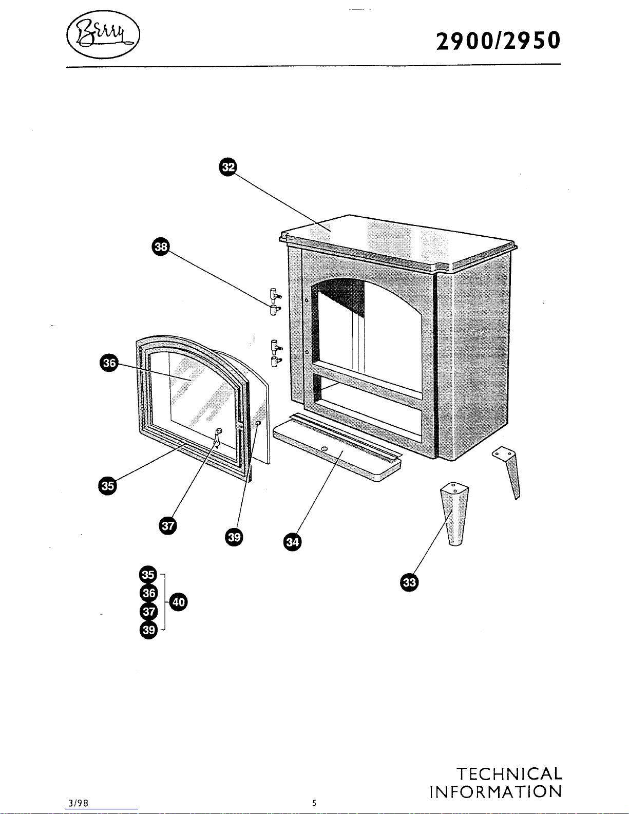
33 FP9945 Foot Black
FP9988 Foot Green
33 FP9946 Control Panel Cover Black
FP9990 Control Panel Cover Green
37 FP9948 Knob (door)
38 FP9950 Hinge (door)
40 FP9949 Door Assembly Black
FP9996 Door Assembly Green
Page 8
Page 9
Page 10
Page 11
Page 12
1
01/01
2920
TECHNICAL
INFORMATION
SPARES
LISTS
FAULT
FINDER
SERVICING
INSTRUCTIONS
SECTION
CONTENTS
Page 13
2
01/01
2920
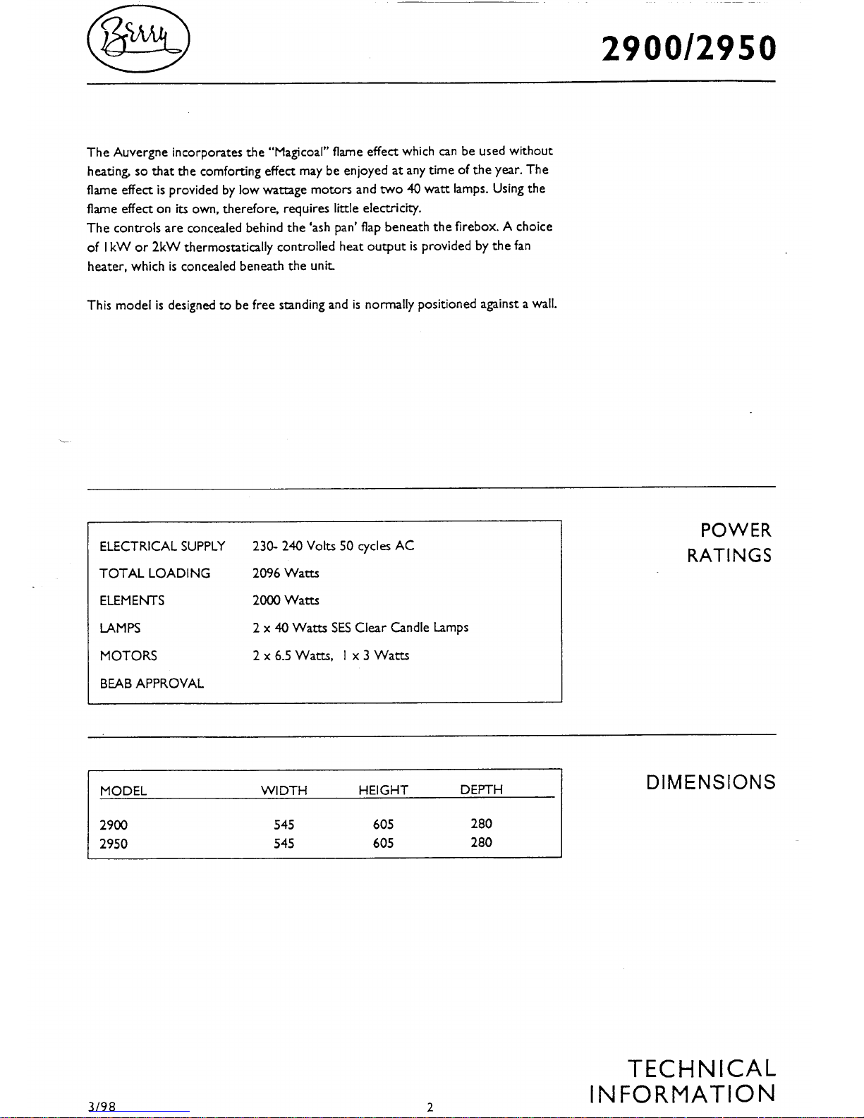
The Auvergne incorporates the “Magilog” flame effect which can be used without
heating, so that the comforting effect may be enjoyed at any time of the year. The
flame effect is provided by low wattage motors and two 40 watt lamps. Using the
flame effect on its own, therefore, requires little electricity.
The controls are concealed behind the ‘ash pan’ flap beneath the firebox. A choice
of 1kW or 2kW thermostatically controlled heat output is provided by the fan
heater, which is concealed beneath the unit.
This model is designed to be free standing and is normally positioned against a wall.
ELECTRICAL SUPPLY 230- 240 Volts 50 cycles AC
TOTAL LOADING 2092 Watts
ELEMENTS 2000 Watts
LAMPS 2x 40 Watts SES Clear Candle Lamps
MOTORS 1x6.5 Watts,2x3 Watts
BEAB APPROVAL
MODEL WIDTH HEIGHT DEPTH
2920 545 605 280
POWER
RATINGS
DIMENSIONS
TECHNICAL
INFORMATION
Page 14
3
01/01
2920
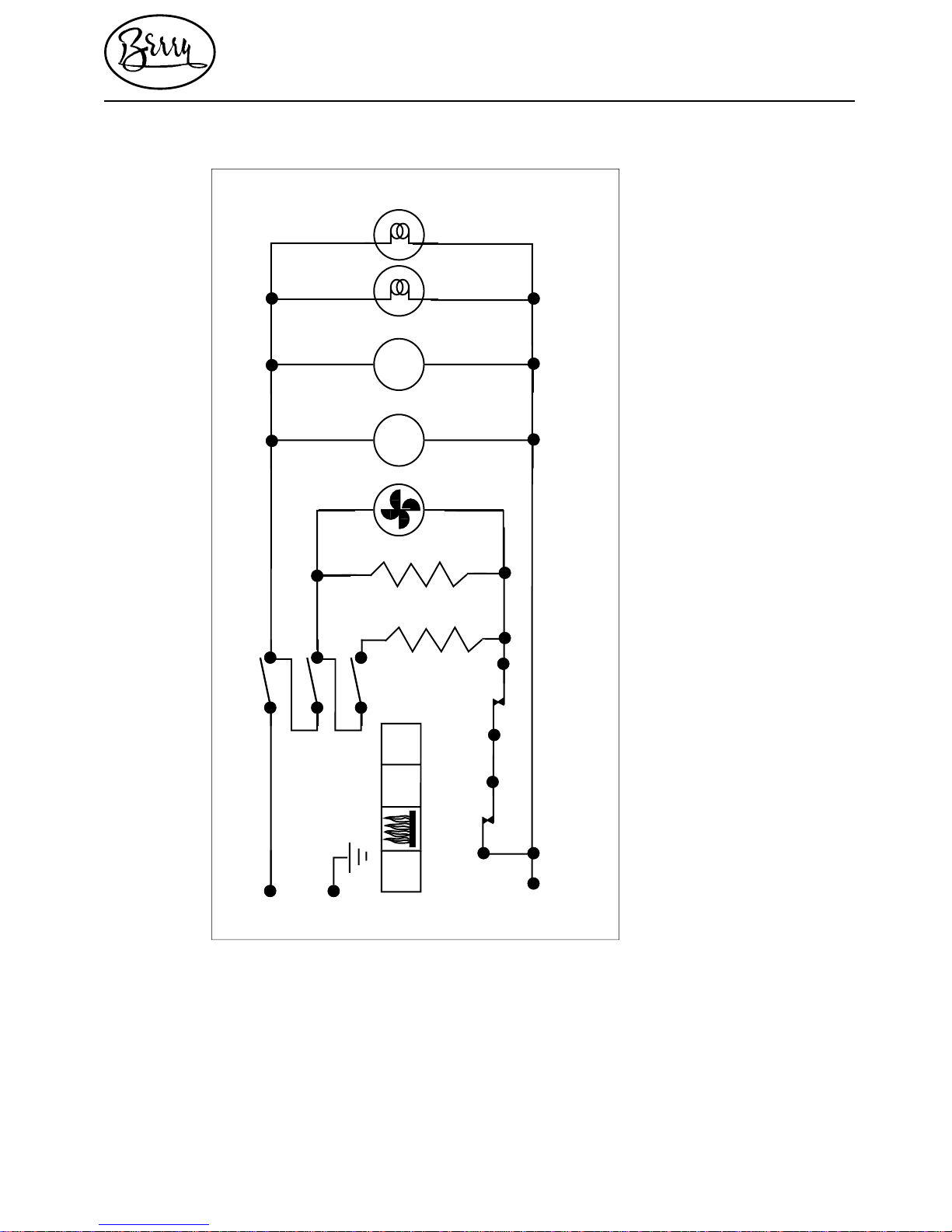
L
E
N
40W
LAMP
40W
LAMP
M
ROTALINK
10 RPM
THERMOSTAT
CUT-OUT
I
II
O
1
2
3
1
HEAT
FAN
1KW
I
II
1KW
2
3
M
ROTALINK
20 RPM
TECHNICAL
INFORMATION
WIRING
DIAGRAM
Page 15
4
01/01
2920
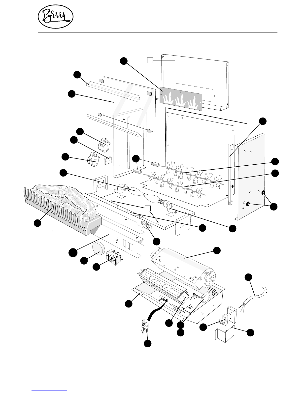
Magilog/SHB 20L
TECHNICAL
INFORMATION
1111
4
32
33
37
38
35
11
15
10
28
22
36
9
18
21
23
24
2
1
3
4
6
8
22
26
25
20
27
B
21
12
212322
13
14
25
15
27 26
16
2919
17
A
5
7
28
Page 16
5
01/01
2920
TECHNICAL
INFORMATION
34
30
33
32
31
35
29
31
33
33
32
Page 17
6
01/01
2920
BF7211 Single Pole Switch
FP9638 Control Knob (Thermostat)
FP9944 Control Panel
FP9927 Fuel Effect Logs & Grate Assembly
FP9610 Lamp 40W Clear SES (Screw In)
FP9929 Geared Motor Assy. 10 RPM*
FP9784 Terminal Block (2 Way) SERIES A
FP9941 Terminal Block (4 Way) SERIES B
FP9930 Geared Motor Assy. 20 RPM*
FP9763 Mirrored Glass Screen
FP9764 Glass Fixing Bracket Top
FP9931 Flame Panel
FP9664 Glass Side Support (2)
FP9934 Rotisserie, Flame (Large)
FP9935 Rotisserie, Log (Small)
FP9787 Grommet Bearing (2)
FP9609 Lamp Holder, SES (2)
FP9938 Reflector
FP9772 Thermostat TSB 141141
FP9557 Heater Blower Unit
FP9120 Plug & Lead Assembly
FP9760 Terminal Plate Cover
BF7469 Mains Tri-Clamp Block
FP9758 Fan Blower Angle Bracket R/H
SPARES
LIST
1
4
4
5
6
3
2
22
21
20
19
18
17
9
10
11
13
12
14
15
16
8
23
7
Page 18
7
01/01
2920
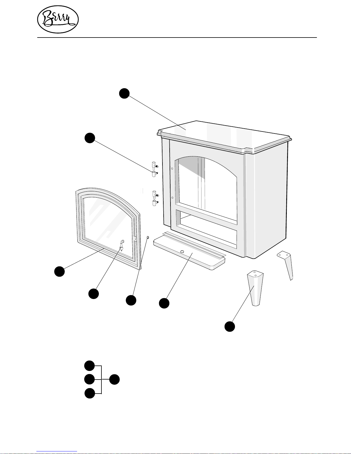
FP9757 Fan Blower Angle Bracket L/H
FP9410 2kW Fan Heater Element Assy.
FB9402 Cut-Out Otter V10
FP9755 Heater Box Assembly
FP9339 Flexible Motor Coupling (2)
FP9945 Foot (4)
FP9946 Control Panel Cover
FP9947 Door Magnet
FP9948 Knob (Door)
FP9949 Door Assembly Complete
FP9950 Hinge (Door)
FP9951 Wood Surround
SPARES
LIST
25
24
27
28
26
30
29
31
32
33
34
35
Page 19
8
01/01
2920
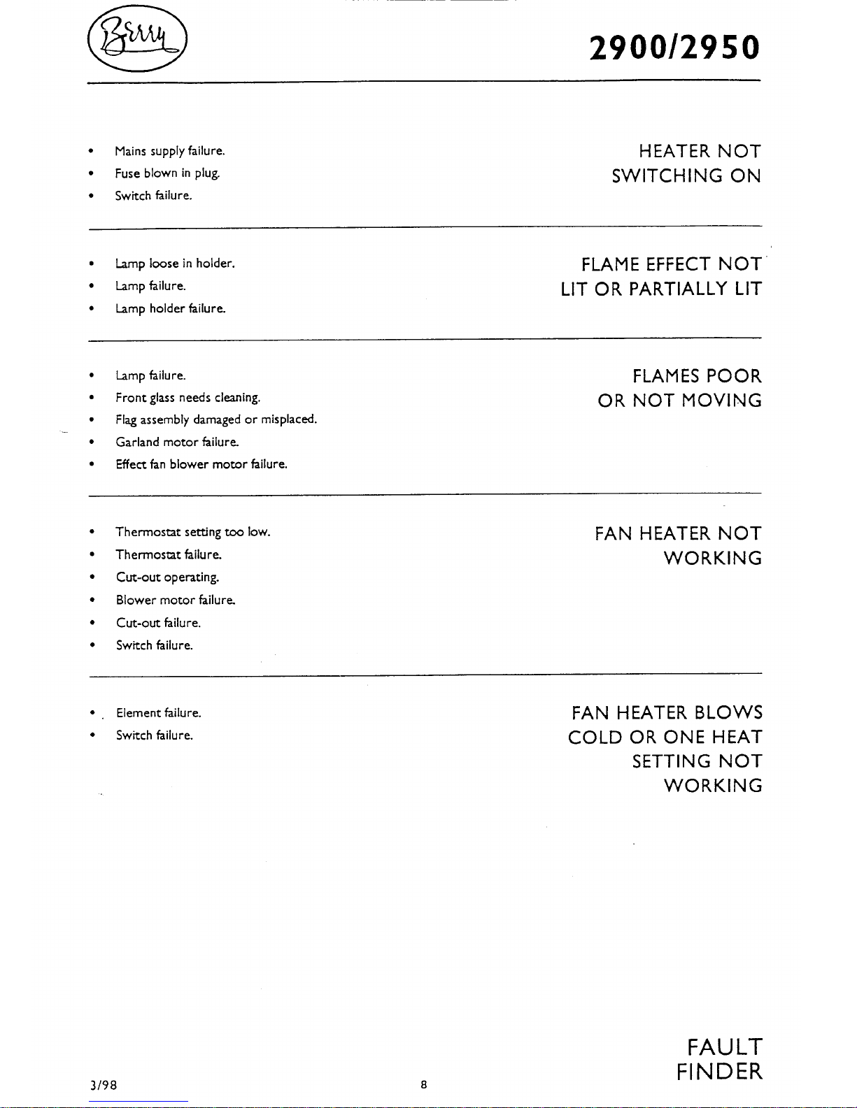
• Mains supply failure.
• Fuse blown in plug.
• Switch failure.
• Lamp loose in holder.
• Lamp failure.
• Lamp holder failure.
• Lamp failure.
• Front glass needs cleaning.
• Garland motor failure.
• Thermostat setting too low.
• Thermostat failure.
• Cut-out operating.
• Blower motor failure.
• Cut-out failure.
• Switch failure.
• Element failure.
• Switch failure.
FAULT
FINDER
HEATER NOT
SWITCHING ON
FLAME EFFECT NOT
LIT OR PARTIALLY LIT
FLAMES POOR
OR NOT MOVING
FAN HEATER NOT
WORKING
FAN HEATER BLOWS
COLD OR ONE HEAT
SETTING NOT
WORKING
Page 20
9
01/01
2920
SERVICING
INSTRUCTIONS
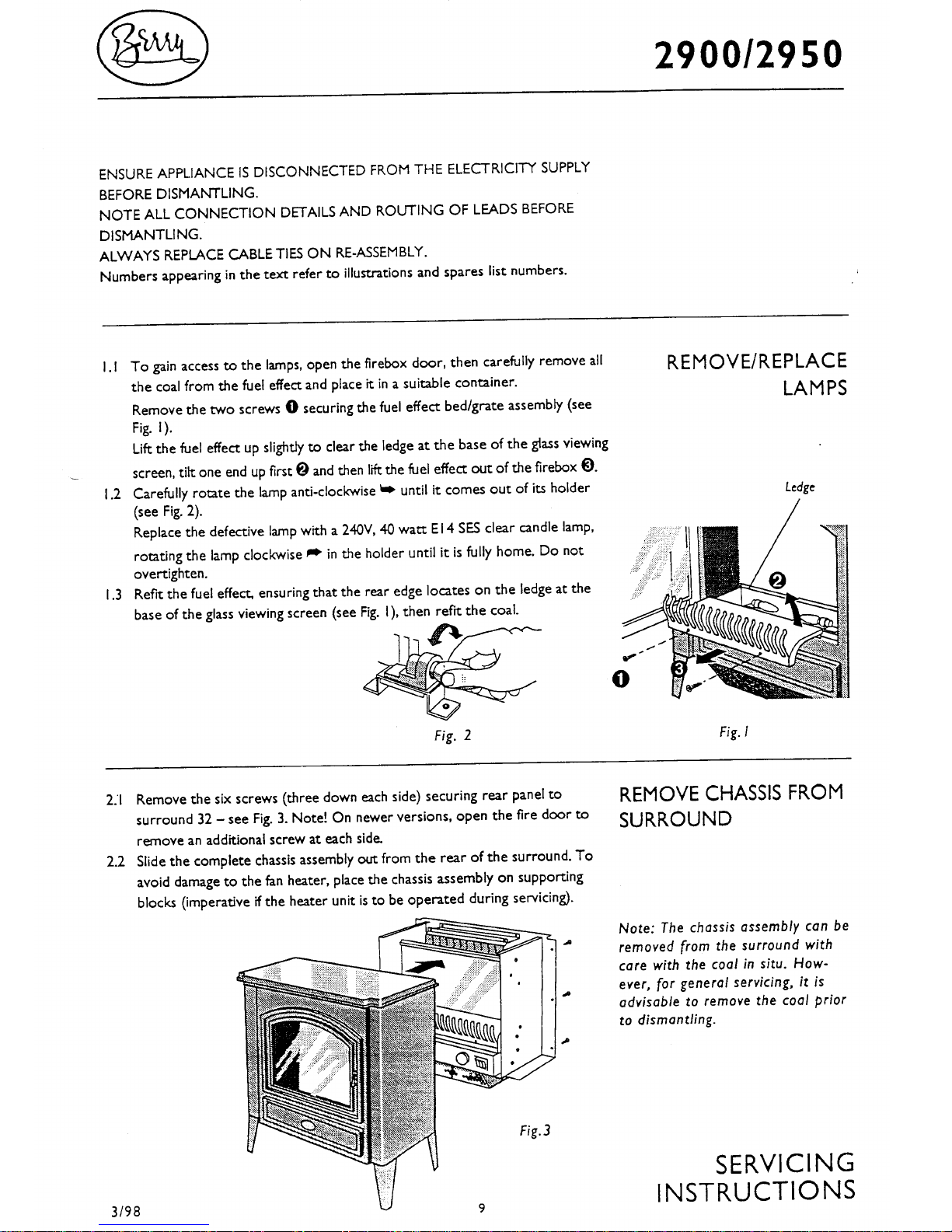
Fig.1
Fig. 2
Fig.3
REMOVE CHASSIS FROM
SURROUND
REMOVE/REPLACE
LAMPS
➌
➊
➋
➥
Ledge
ENSURE APPLIANCE IS DISCONNECTED FROM THE ELECTRICITY SUPPLY
BEFORE DISMANTLING.
NOTE ALL CONNECTION DETAILS AND ROUTING OF LEADS BEFORE
DISMANTLING.
ALWAYS REPLACE CABLE TIES ON RE-ASSEMBLY.
Numbers appearing in the text refer to illustrations and spares list numbers.
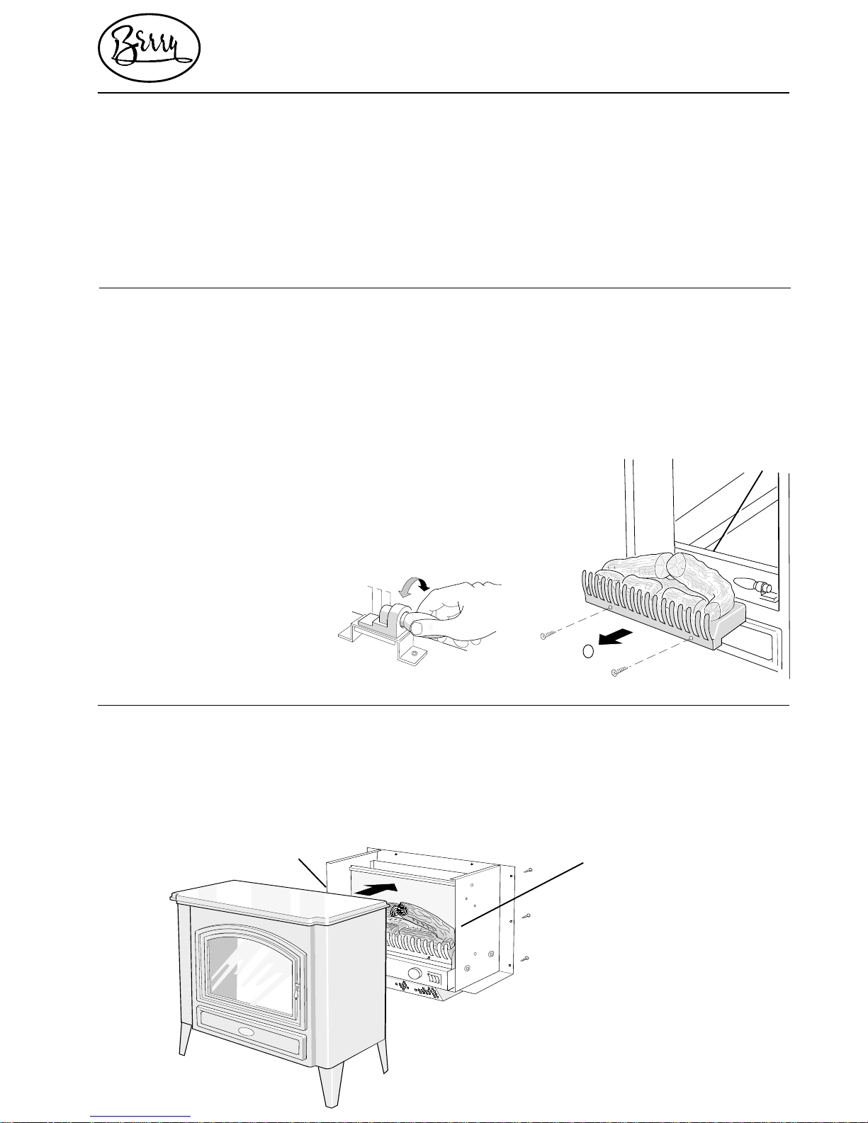
1.1 To gain access to the lamps, open the firebox door, then remove the two
screws ➊ securing the fuel effect logs and grate assembly (see Fig. 1).
Lift the fuel effect up slightly to clear the ledge at the base of the glass
viewing screen, tilt one end up first ➋ and then lift the fuel effect out of the
firebox ➌.
1.2 Carefully rotate the lamp anti-clockwise ➥ until it comes out of its holder
(see Fig. 2).
Replace the defective lamp with a 240V, 40 watt E14 SES clear candle lamp,
rotating the lamp clockwise ➦ in the holder until it is fully home. Do not
overtighten.
1.3 Refit the fuel effect, ensuring that the rear edge locates on the ledge at the
base of the glass viewing screen (see Fig. 1)
2.1 Remove the six screws (three down each side) securing rear panel to
surround 35, and the two screws ➊ located above the fuel effect through
the sides of the chassis (see fig. 3). Slide the chassis assembly out from the
rear of the surround.
2.2 To avoid damage to the fan heater, place the chassis assembly on blocks
(imperative if the heater unit is to be operated during servicing).
➊
➊
Page 21
10
01/01
2920
SERVICING
INSTRUCTIONS
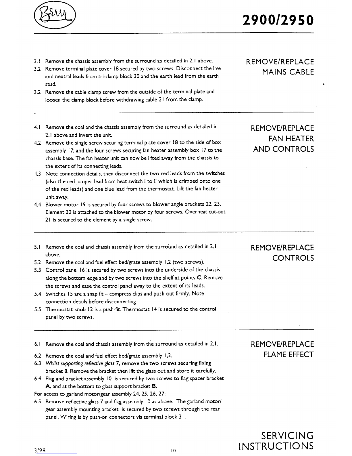
3.1 Remove the chassis as described in Sections 2.1and 2.2 above.
3.2 Remove the terminal plate cover 21 secured by two screws.
Disconnect the live and neutral leads from tri-clamp block 22
and the earth lead from the earth stud.
3.3 Remove the cable clamp screw from the outside of the terminal
plate and loosen the clamp block before withdrawing cable 20
from the clamp.
REMOVE/REPLACE
MAINS CABLE
REMOVE/REPLACE
FAN HEATER
AND CONTROLS
4.1 Remove the chassis assembly from the surround as detailed in 2.1 and 2.2
above and invert the unit.
4.2 Remove the single screw securing terminal plate cover 21 to the side of box
assembly 27, and the four screws securing fan heater assembly box 27 to the
chassis base. The fan heater unit can now be lifted away from the chassis to the
extent of its connecting leads.
4.3 Note connection details, then disconnect the two red leads from the switches
(also the red jumper lead from heat switch I to II which is crimped onto one of
the red leads) and one blue lead from the thermostat. Lift the fan heater unit
away.
4.4 Blower motor 19 is secured by four screws to blower angle brackets 23, 24.
Element 25 is attached to the blower motor by four screws. Overheat cut-out
26 is secured to the element by a single screw.
5.1 Remove the chassis assembly from the surround as detailed in 2.1 and 2.2
above.
5.2 Remove the fuel effect assembly 4 (two screws).
5.3 Control panel 3 is secured by two screws into the underside of the chassis
along the bottom edge and by two screws into the inner base at points A.
Remove the screws and ease the control panel away to the extent of its leads.
5.4 Switches 1 are a snap fit – compress clips and push out firmly. Note connection
details before disconnecting.
5.5 Thermostat knob 2 is a push-fit. Thermostat 18 is secured to the control panel
by two screws.
6.1 Remove the chassis assembly from the surround as detailed in 2.1. and 2.2
above.
6.2 Remove the fuel effect logs and grate assembly 4 (two screws).
6.3 Whilst supporting reflective glass 9, remove the two screws securing fixing
bracket 10. Remove the bracket then lift the glass out and store it carefully.
6.4 The flame panel 11 is secured to the flame holder panel B by two screws, the
flame holder panel is secured to the inner side panels by four screws.
For access to Rotalink motor/gear assembly 6 and 8 :-
6.5 Remove the chassis and the fuel effect assembly as detailed in sections 6.1, 6.2
above. The Rotalink assemblies are each secured by two screws through the
inner-side panel. Wiring is by push-on connectors via terminal block 7.
6.6 Note: On Series A production, the Rotalink motor leads are crimped together
into the spade terminals which connect to a two-way terminal block 7. When
REMOVE/REPLACE
CONTROLS
REMOVE/REPLACE
FLAME EFFECT
Page 22
11
01/01
2920
replacing a motor/gear assembly 6 or 8, use conversion kit FP9940 to modify
connections – see parts list.
Series B production has individual motor leads connecting to a 4-way terminal
block 7.
To remove/replace lamp holders:
6.7 Remove the chassis assembly and the fuel effect assembly as detailed in
sections 6.1 and 6.2 above.
6.8 Detatch the fan heater assembly as detailed in section 4.2 above.
6.9 Lamp holders 16 are a snap fit in the inner base panel and are secured by a
single screw. Leads are connected by push-in single-use spring clips. Use a
small screwdriver or similar to compress clip and remove lead. DO NOT
DISCONNECT LEADS UNLESS REPLACING A DEFECTIVE LAMP
HOLDER.
7.0 When re-assembling, ensure that the reflective glass is fitted the correct way
round - with the reflective side facing outwards.
AFTER SERVICING, IT IS RECOMMENDED THAT THE PRODUCT IS TESTED
FOR INSULATION AND EARTH CONTINUITY, IN ACCORDANCE WITH
RELEVANT LOCAL SAFETY REGULATIONS.
SERVICING
INSTRUCTIONS
REMOVE/REPLACE
FLAME EFFECT
CONT’D
 Loading...