

BERNSTEIN ITR 10 Important Notes For Installation & Warranty Card

ITR 10
Wichtige Hinweise zur Installation / Garantieurkunde
Important notes for installation / warranty card
Mode d’emploi / certificat de garantie
Avvertenze importanti per l’installazione / certifcato di garanzia
Notas importantes sobre la instalación y certificado de garantía
/Важная информация по инсталляции гарантия


Inhaltsverzeichnis
Sicherheitshinweise / Entsorgungshinweise / Lieferumfang S. 5
Abbildungen S. 6, 7
Inbetriebnahme S. 8
Anschlüsse und Funktionen des Bernstein ITR 10 S. 9, 10
Besonderheiten S. 11
Technische Daten S. 12
Garantiebedingungen / Garantiekarte S.
53/54
Contents
Safety precautions / Instructions for disposal / Scope of delivery p. 13
Illustrations p. 14, 15
Initial operation p. 16
Connections and functions of the ITR 10 p. 17, 18
Special features p. 19
Specifications p. 20
Warranty conditions / warranty card p.
53/54
Sommaire
Consignes de sécurité / Instructions pour la mise au rebut /
Éléments fournis p. 21
Illustrations p. 22, 23
Mise en service p. 24
Connecteurs et fonctions de l'ITR 10 p. 25, 26
Spécificités p. 27
Caractéristiques techniques p. 28
Conditions de garantie / carte de garantie p.
53/54
3

Indice
Avvertenze di sicurezza / Avvertenze per lo smaltimento / Fornitura P. 29
Figure P. 30, 31
Messa in funzione P. 32
Attacchi e funzioni della ITR 10 P. 33, 34
Particolarità P. 35
Dati tecnici P. 36
Condizioni di garanzia / Scheda di garanzia P.
53/54
Índice
Precauciones de seguridad / Instrucciones de eliminación /
Volumen de sumistro P. 37
Ilustraciones P. 38, 39
Primeros pasos P. 40
Conexiones y funciones del dispositivo ITR 10 P. 41, 42
Funciones P. 43
especiales
Especificaciones P. 44
Condiciones de garantía / tarjeta de garantía p.
53/54
Содержание
Указания по безопасности Указания по утилизации
Объем поставки стр.
Иллюстрации стр.
Включение стр.
Разъемы и функции стр.
Особенности стр.
//
45
46, 47
48
ITR 10 49, 50
51
52Технические данные стр.
Гарантийные условия / Гарантийная карточка стр.
53/54
4

Sehr geehrterKunde,
vielen Dank, dass Sie sich für die Bernstein ITR 10 Stereo-Docking-Station
entschieden haben.
Bitte lesen Sie unsere folgenden Hinweise vor Inbetriebnahme der ITR 10 genau
durch.
Sicherheitshinweise
Setzen Sie das Gerät und die Fernbedienung weder Wasser noch Feuchtigkeit
•
aus.
Betreiben Sie das Gerät nur im angegebenen Temperaturbereich von 0°C bis 40°C.
•
Sorgen Sie für eine ausreichende Belüftung des Gerätes. Ein Mindestabstand von
•
10 cm zu Gegenständen seitlich, nach hinten und oben sollte nicht unterschritten
werden.
Bei Kontakt mit Feuchtigkeit oder Flüssigkeiten sofort den Netzstecker ziehen.
•
Reinigen Sie das Gerät nur mit einem trockenen Tuch. Verwenden Sie keine
•
Reinigungsmittel oder chemische Lösungsmittel, da sonst die Oberfläche
beschädigt werden könnte.
Öffnen Sie niemals das Gerät.
•
Bei sichtbaren Beschädigungen des Netzkabels darf das Gerät nicht mehr
•
betrieben werden. Ein beschädigtes Kabel darf nicht repariert, sondern muss
ausgetauscht werden.
Überlassen Sie Wartungs- oder Reparaturarbeiten immer qualifiziertem
•
Fachpersonal.
Entsorgungshinweise
Gemäß der europäischen Richtlinie 2002/96/EC müssen alle
elektrischen und elektronischen Geräte über lokale Sammelstellen
getrennt entsorgt werden. Bitte beachten Sie die lokalen
Vorschriften und entsorgen Sie Ihre Altgeräte nicht mit dem
normalen Hausmüll.
Lieferumfang
AM-Antenne, FM-Antenne
•
Fernbedienung inkl. Batterie
•
Pod-Adapterschale (2 St.)
•i
Audio-Anschlusskabel mit 3,5 mm Stereo-Klinkenstecker
•
Ausführliche Bedienungsanleitung
•
5

Abb.1 Rückseite / Anschlüsse und Netzschalter
3 4 5 6 7 2 1
Abb.2 Oberseite / Hauptbedienfeld / iPod-Dock
Vertiefung für
iPod-Adapterschale
Schutzabdeckung
iPod
Systemstecker
B
C
6
A
D

INBETRIEBNAHME
Allgemein
•
Entfernen Sie die Schutzfolie am Batteriefach der Fernbedienung (Abb. 4).
Verbinden Sie das Netzkabel mit dem Stromversorgungseingang an der
•
Rückseite des Gerätes (Abb. 1, Pos. 1).
Stecken Sie den Netzstecker in eine Netzsteckdose.
•
Schalten Sie den Netzschalter ein (Abb. 1, Pos. 2). Das Gerät ist nun im
•
Standby-Modus, und Sie können mit der Powertaste (Abb. 2, Pos. A oder Abb. 4,
Pos. 1) in den Betriebsmodus wechseln. Trotz geringer Stromaufnahme im
Standby-Modus empfehlen wir, das Gerät am Netzschalter auszuschalten, wenn
es längere Zeit nicht benutzt wird.
• Wählen Sie eine Eingangsquelle (siehe S. 9, Hauptfunktionen des ITR 10).
Bei Nutzung des Radios
•
UKW:
Schließen Sie das ITR 10 mit einem handelsüblichem Kabel an eine
Antennenanlage an, oder benutzen Sie die mitgelieferte Wurfantenne (Abb. 1,
Pos. 3).
•
Benutzen Sie die mitgelieferte Ringantenne (Abb. 1, Pos. 4).
MW:
Bei Nutzung des ipod-Docks
•
Entfernen Sie die Schutzabdeckung am iPod-Systemstecker (Abb. 2).
•
Wählen Sie die zu Ihrem iPod-Modell passende Adapterschale und setzen Sie
sie in die Vertiefung am Gerät ein (Abb. 2). Es können auch Original-iPodAdapterschalen verwendet werden.
•
Entfernen Sie die Schutzabdeckung für den iPod-Anschluss am ITR 10.
•
Stecken Sie Ihren iPod auf den Systemstecker und drücken Sie ihn leicht nach
unten bis zum Anschlag. Der iPod ist leicht nach hinten geneigt.
Ladefunktion des iPods
•
Der Akku des iPods wird geladen, wenn das ITR 10 eingeschaltet ist
(unabhängig von der gewählten Eingangsquelle).
•
Im Standby-Modus wird diese Ladefunktion nicht unterstützt.
Auswechseln der Batterie für die Fernbedienung
Funktioniert die Fernbedienung nicht mehr einwandfrei, muss die Batterie gemäß
Abb. 3 ausgetauscht werden. Verwenden Sie eine Lithium Knopfzelle CR2025 und
achten Sie auf die Polung.
Batterie-Entsorgung:
Alt-Batterien sind Sondermüll und müssen gemäß den aktuellen Vorschriften
entsorgt werden.
8

Abb.3 Vorderseite / Tunerbedienung
132
554
Abb.4
Fernbedienung
10
21
4
3
6
5
7
8
9
7
Anschlüsse und Funktionen des ITR 10
Rückseite des ITR 10
Abb Nr. Bezeichnung Funktion Bemerkungen
1
1
Netzeingang 230 V Wechselstrom
Anschluss für das
Netzkabel
12
1
Netzschalter Schaltet das Gerät
ein
3
FM ANTENNA Anschluss einer
Trennt das Gerät vollständig
vom Stromnetz
75 Ohm, zum Empfang nötig
UKW Antenne
4
1
AM ANTENNA Anschluss einer
300 Ohm
Mittelwellenantenne
15
16
17
S-VIDEO OUT Anschluss eines
TV Gerätes
LINE 2 INPUT Anschluss einer
weiteren Audioquelle
SUB OUT Anschluss eines
Subwoofers
Gibt das Bild eines VideoiPods auf einem TV-Gerät aus
Cinch-Buchsen zum Anschluss
eines CD-Players o. ä.
Bass-Ausgang für Subwoofer
mit Cinch-Eingang
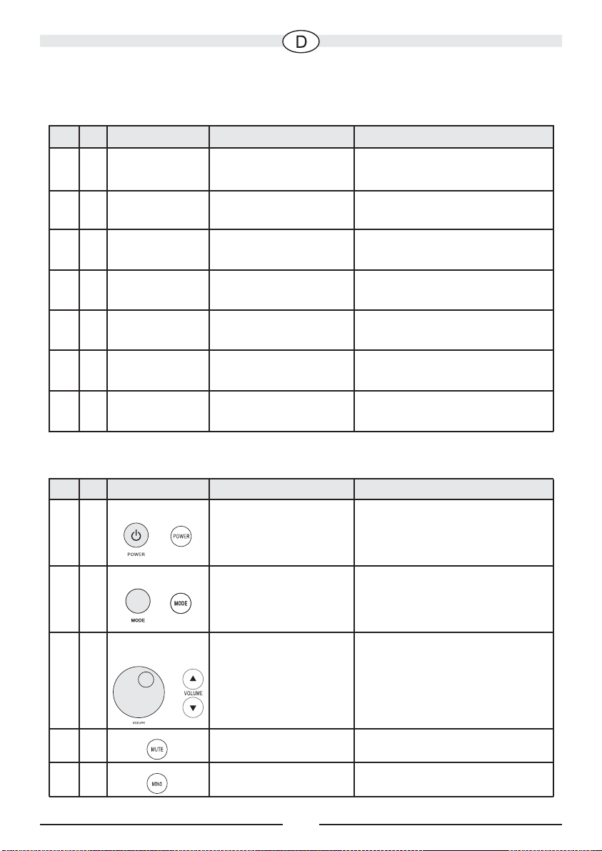
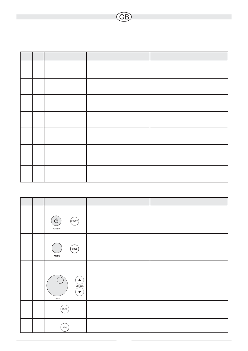
Hauptfunktionen des ITR 10 (über Top-Panel oder Fernbedienung)
Abb Nr. Bezeichnung Funktion Bemerkungen
2/4 A/1 Power/Standby
Umschalten von
Standby auf Betrieb
oder von Betrieb auf
Standby
2/4 B/2
2/4
Mode
Mode
Wahl zwischen
Wahl zwischen
Wiedergabe vonWiedergabe von
Wiedergabe vonWiedergabe von
Radio, iPod oder 2
Radio, iPod oder 2
Modus wird auf dem Top Panel
mit LEDs angezeigt (Bild 2,
pos. D)
weiteren Audioquellen
2/4 C/3
Lautstärkesteuerung
Regulierung der
Lautstärke
44
410
Mute
Mono
stummschalten
auf
Mono/Stereo schalten
9
Nur über die FernbedienungAudiowiedergabe
Nur über die FernbedienungRadiowiedergabe
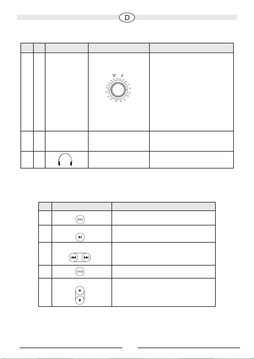
Front-Panel des ITR 10 (Abb. 3)
Abb Nr. Bezeichnung Funktion Bemerkungen
3
1
TUNING
Einstellen der Radiostationen mit dem
Drehknopf
Die Sendereinstellung wird mit
der Leuchtanzeige “TUNE”
kontrolliert (Abb. 3, Pos. 2).
Bei optimalen Empfang
leuchtet sie am hellsten.
Sendet die empfangene
Die obere Skala zeigt
die Senderfrequenz
für UKW, die untere
Station stereofon, leuchtet die
“STEREO” Anzeige (Abb. 3,
Pos. 3).
die für MW
34
LINE 1
Anschluss einer
weiteren Audioquelle
Anschluss eines MP3 Players
o. ä. über ein Kabel mit
3,5 mm Klinkenstecker
35
Anschluss eines
Stereokopfhörers
iPOD-Funktionen auf der Fernbedienung (Abb. 4)
Bezeichnung
Nr.
5
Menu
Funktion
Sprung zum übergeordneten
Auswahlmenü
Play / Pause
6
Wiedergabe / Pause
Skip prev. / Skip next
7
Enter
8
Up / Down
9
Vorigen / nächsten Titel
abspielen
Auswahl des aktuellen Menüpunktes
Vertikales Navigieren im aktuellen
iPod-Menü
10
Besonderheiten
•
Stereo-Docking-Station mit integriertem Sound-System für iPod, AM/FM-Radio
•
High-End-Hybridverstärker mit kanalgetrennten Röhrenvorstufen und HalbleiterLeistungsendstufen
•
Bassreflex-Prinzip (kanalgetrennt)
•
Stabile und resonanzarme Holzkonstruktion
•
Aufwändige akustische Entzerrung durch analoge Filter im Verstärkerteil
•
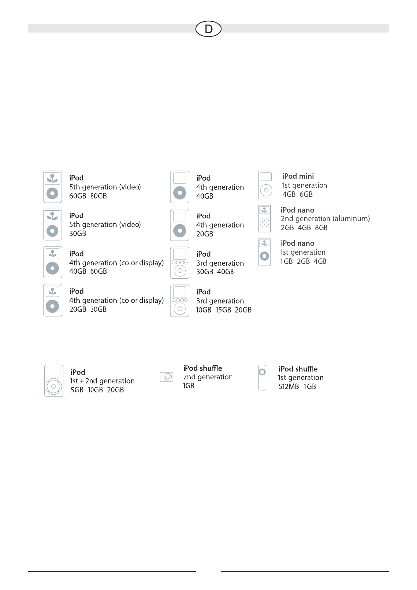
Passend für:
Über den AUX-Eingang und einen zusätzlichen 3,5 mm Klinkenstecker können
folgende Geräte angeschlossen werden:
& weitere MP3-Player
•
Ladefunktionen für iPod
•
Infrarot-Fernbedienung zur Steuerung aller iPod-Funktionen
•
Offiziell lizensiert vonApple Computer, Inc., U.S.
11

Technische Daten
•
2 St. 80 mm Breitband-Lautsprecher mit extraleichter Zellulosemembran und
Neodym-Antrieb
•
Frequenzgang: 42 Hz – 20 kHz
•
Verstärkerleistung:2 x 12 Watt RMS und 50 Watt Gesamtmusikleistung
•
Stromversorgung 230 VAC, 50 Hz, eingebautes Netzteil
•<1
W Leistungsaufnahme im Standby-Betrieb
•
Abmessungen B x H x T: 350 x 120 x 290 mm
12

Dear customer,
thank you for choosing the ITR 10 Stereo Docking Station from Bernstein.
Please read the following information carefully before starting to use your ITR 10.
Safety precautions
• Donot expose the device and the remote control to water or moisture.
• Onlyoperate the device in the specified temperature range of 0°C to 40°C.
• Make sure there is sufficient ventilation for the device. There must be a minimum
gap of 10 cm between objects to the side, to the rear and above the device.
• In the event of contact with moisture or liquids remove the mains adapter
immediately.
•
Only clean the device using a dry cloth. Do not use any cleaning agents or chemical
solvents when cleaning, as these could damage the surface of the device.
• Neveropen the device.
• The device should not continue to be operated if there is visible damage to the
mains cable. Adamaged cable should not be repaired, but must be replaced.
• Alwaysrefer to a qualified specialist for any maintenance or repair work.
Instructions for disposal
In accordance with European Directive 2002/96/EC all electrical and
electronic appliances must be disposed of separately via local collection
points. Please observe the local regulations and do not dispose of your
old appliances with normal household waste.
Scope of delivery
• AM aerial, FM aerial
• Remote control incl. battery
• iPod adapter/holder (2 pce.)
• Audio connecting cable with 3.5 mm stereo jack
• Detailed instruction manual
13
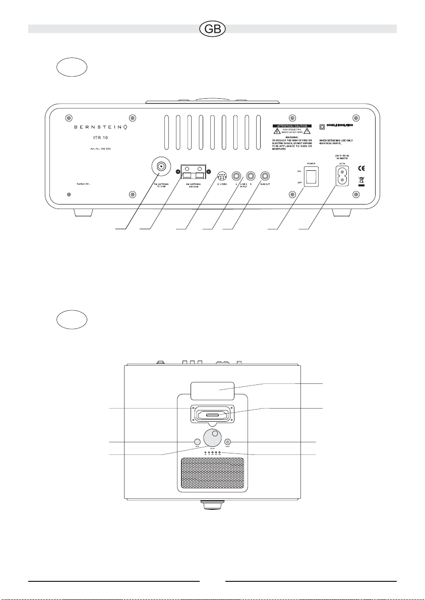
Fig.1
Rear / connections and on/off switch
3 4 5 6 7 2 1
Fig.2
Recess for iPod
adapter/holder
system plug
Top / iPod dockmain control panel /
B
C
Protective cover
iPod system
plug
A
D
14
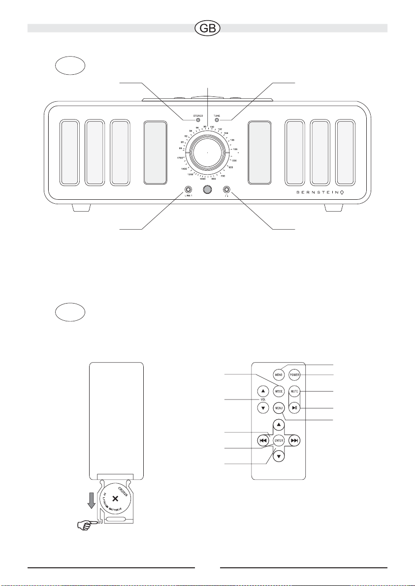
Fig. 3
Front / tuner operation
132
554
Fig. 4
Remote control
10
21
4
3
6
5
7
8
9
15

Initial operation
General
Remove the protective film from the battery compartment of the remote control (fig.
•
4).
•
Connect the mains cable to the power supply input on the rear of the device (fig. 1,
pos. 1).
•
Insert the mains plug into a compatible socket.
•
Actuate the on/off switch. (fig. 1, pos. 2). The device is now in the standby mode;
you can change to the operating mode using the power button (fig. 2, pos. A or fig. 4,
pos. 1). Despite a low degree of energy consumption in the standby mode we
recommend that you switch the device off at the mains if it is not going to be used for
a prolonged period.
•
Select an input sou nctions of the ITR 10).
rce (see p. 17, main fu
Using the radio
•
Connect the ITR 10 to an aerial installation using a commercial cable or use the
FM:
provided aerial (fig. 1, pos. 3).
•
: Use the provided ring aerial (fig. 1, pos. 4).
MW
Using the iPod dock
•
Remove the protective cover from the iPod system plug (fig. 2).
•
Choose the compatible adapter/holder for your model of iPod and place it in the
recess in the device (fig. 2). Original iPod adapter/holders can also be used.
•
Remove the protective cover for the iPod connection on the ITR 10.
•
Place your iPod on the system plug and press it down lightly as far as it will go. The
iPod is inclined slightly to the rear.
Charging function of the iPod
The iPod's battery is charged when the ITR 10 is switched on (independent of the
input source selected). This charging function is not supported in the standby mode.
Replacing the battery in the remote control
If the remote control stops working properly, you will need to change the battery in
accordance with fig. 3. Use a lithium button cell (CR2025) and pay attention to the
correct polarity.
Battery disposal
Old batteries are hazardous waste and must be disposed of in accordance with
current regulations.
16
Connections and functions of the ITR 10
Rear of the ITR 10
Fig. No. Description Function Notes
1
1
POWER INPUT
Connection for
230 V alternating current
the mains cable
12
1
1
Mains switch Switches the device
on
3
FM AERIAL
Connection of an
FM aerial
4
AM AERIAL
Connection of an
Completely separates the
device from the mains supply
75 Ohm, required for
reception
300 Ohm
AM/MW aerial
15
16
S-VIDEO OUT
LINE 2 INPUT
Connection of a
TV appliance
Connection of another
audio source
Transfers the image from
a video iPod to a TV
RCA phono socket for
connecting a CD player or
similar device
17
SUB OUT
Connection of a
subwoofer
Bass output for subwoofers
with RCA phono input
Main functions of the ITR 10 (via top panel or remote control)
Fig. No. Description
2/4 A/1 Power/Standby
Function
Switching from
Notes
Standby to ON or
from ON to Standby
2/4
2/4 B/2
Mode
Selection between
playback from radio,
Mode is displayed on the top
panel LEDs (fig. 2, pos. D)
iPod or 2 other audio
sources
2/4 C/3
Volume control
Adjusting the volume
44
410
Mute
Mono
Only via remote controlDisconnecting audio
playback
Only via remote controlRadio playback
mono/stereo switch off
17
 Loading...