

F
Common Features of Electromechanical Switches
F
Switching systems
Switching elements lie at the heart of
all electromechanical switching devices
and must correspond to the respective
application. Essentially there are two basic
types of switching system that differ in terms
of their mechanical design and consequently
their scope of application:
l Slow-action contacts
l Snap-action contacts
Slow-action contacts
l On actuation, the normally-closed
and normally-open contact functions
Fig. 2 shows the contact force during the
switching cycle of a slow-action contact
with overlap.
correspond to the movement of the
impact pin
l The approach speed controls the contact
opening (closing) time
l Large distance / actuating travel
between normally-closed and normallyopen contact function
l The switching points are identical in
forward and reverse travel
F
Lag between NC and NO
contact function
Snap-action contact
l On actuation, the normally-closed
contact function is immediately followed
by the normally-open contact function
l In this configuration there is no overlap
of the NC/NO contacts. The switch
provides a distinct OR-function.
l The changeover accuracy is not
dependent on the approach speed
l Consistently effective suppression
of DC arc
l Reliable contact-making also for
extremely slow approach speeds
S
l The snap mechanism triggers the
full opening width of the contact on
reaching the changeover point
l Due to the force reversal in the
mechanical system, a different switching
point occurs in forward and reverse
travel. The lag is referred to as hysteresis.
Fig. 1 shows the contact force during the
switching cycle of a slow-action contact.
Overlap
l The switching principle of snap-action
contacts makes overlapping of the NC /
NO contact function possible. The term
overlap refers to the area, in which both
the normally-closed contact as well as
the normally-open contact are closed in
connection with a changeover switch
with delay.
Fig. 3 shows the contact force during the
switching cycle of a snap-action contact.
1)
Changeover point in forward travel
2)
Changeover point in reverse travel
Lag between NC and NO
contact function
S
Lag
(hysteresis)
S
2) 1)
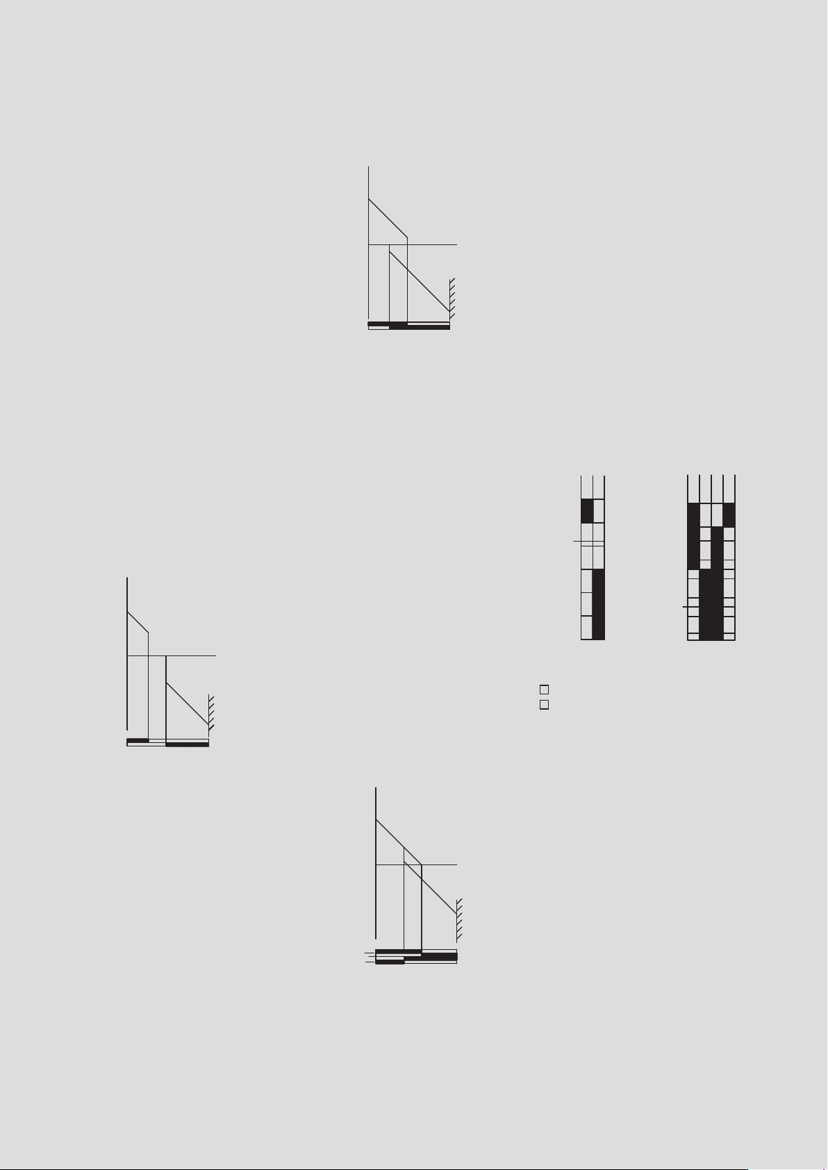
Switching diagram
The switching diagram describes the
function of the switching device in detail.
It combines the mechanical input
variables that act on the contact system
via the actuator with the electrical output
variables. The user can deduct the following
information from the switching diagram:
l Mechanical input variables
(force, travel, torque, angle)
l Electrical contact-making in forward
and reverse travel
l Terminal designation
l Point at which positive opening
is achieved
l Type of contact system
23-24
11-12
2N
0
1
1.8
3
12,5N
6
0
10
35
55
75
21-22
13-14
13-14
21-22
6.5Ncm
6Ncm
Slow-action contact Snap-action contact
Contact closed
■
Contact open
■
Contact designation
In accordance with DIN 50013 and DIN 50005
the terminal designations of the contact
elements are always make up of two digits.
The contact rows are numbered
consecutively with the allocating digit
(1st digit) in actuation direction. Contacts
of a switching element that belong
together have the same allocating digit.
The second digit is the function digit that
denotes the type of contact element.
1–2 Normally-closed contact
3–4 Normally-open contact
5–6 Normally-closed contact with
delayed opening
7–8 Normally-open contact with
delayed closing
12
Protection class
Enclosures
Safety switches
The protection class of an enclosed
device denotes the degree of protection.
The degree of protection includes the
protection of persons against contactwith
parts under voltage and the protection of
equipment against the infiltration of foreign
bodies and water. BERNSTEIN standard
enclosures mainly correspond to protection
classes IP65 and IP67. Higher protection
ratings are also available for individual
customer solutions. In accordance with DIN
EN 60521 (IEC 529), the numerals used in
the protection rating denote the following:
1st digit Degree of protection against
contact and infiltration of foreign bodies
2nd digit Degree of protection against
infiltration of water
Example IP65:
6 =
l
Complete protection against contact
with components under voltage or
with internal moving parts
l
Protection against dust infiltration
5 =
l
A water jet directed from all directions
at the device must not have damaging
effects
l
Protection against hose water
Limit switches are supplied either in a
plastic enclosure or a metal enclosure.
Which material is to be selected for a
specific application depends on the
ambient conditions, the location as well
as several other factors.
Plastic limit switches provide protective
insulation and are resistant to many
aggressive chemicals and liquids.
The formation of condensation water
in moist environments with extreme
temperature fluctuations is
significantly
reduced on plastic enclosures.
In insulation-enclosed switches the
switching elements are integrated directly
in the plastic enclosure and are therefore
not replaceable (complete switching
devices).
Metal-enclosed limit switches are able to
withstand high mechanical loads, they
can also be used wherever hot metal chips
and sparks occur and are resistant to many
solvents and detergents. The switching
elements in metal-enclosed switches are
often integrated in the metal enclosure as
modular built-in switches. The enclosure
has a VDE-compliant connection for the
PE conductor.
The scope of application for limit switches
has changed over time. Whereas limit
switches were previously used for the
purpose of detecting end positions, today
they are increasingly assuming functions
designed
machine,
to protect persons and products in
equipment and plant construction.
The BERNSTEIN range of safety switches
offers the right solution for the most diverse
applications in many branches of industry.
Particularly when it comes to safety, users
appreciate the fact that they are able to
procure all required safety switches and
receive professional advice from one source.
The decisive factors governing the selection
of safety equipment include the ambient
conditions, installation situation and risk
analysis.
A switching device that can be used
for safety functions is identified by the
standardised symbol conforming to
EN 60947-5-1 Addendum K. The switches
can, of course, also be used for pure
position monitoring purposes.
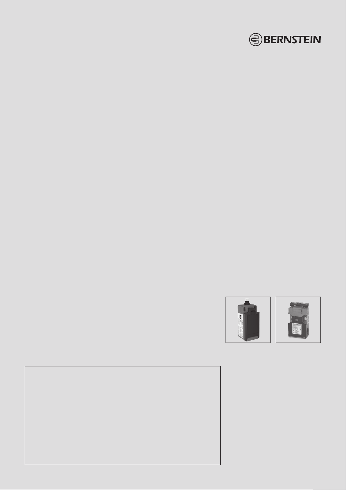
Safety switches are divided into two
categories, Type 1 and Type 2. The difference
is in the actuating elements which are
com
pletely integrated in the enclosure in
Type 1
and separated from the switching
element in Type 2.
Designation
The designation of BERNSTEIN switching devices depends on:
l The enclosure designation of the switching device
l The switching function
l The type of actuator
Type code of position and safety switches
IN65
Switch group
l C2
l Ti2
l I49
l IN62, IN65, I81
l Bi2
l ENK
l GC
A2Z
Switching system
l U1
l SU1
l A2
l SA2
l E2
l SE2
l UV1
2)
AH
Actuator
See Pages
68 – 69
1)
l SN2
l ENM2
l D
M12
Special features
l M12 connection
l Actuator turned
90°, 180°, 270°
l Special switching
forces
l Special temperature
ranges
l Other special
features on request
Type 1 Type 2
1)
The letter Z suffix to the designation
of the switching function denotes the
mechanical positive opening action of
the normally-closed contacts. In technical
data sheets, the positive opening point is
identified by the international symbol �.
2)
Please refer to the following pages in the
catalogue to establish which switching
system can be used in the switch groups.
13
 Loading...