

Page 1
Technical Data
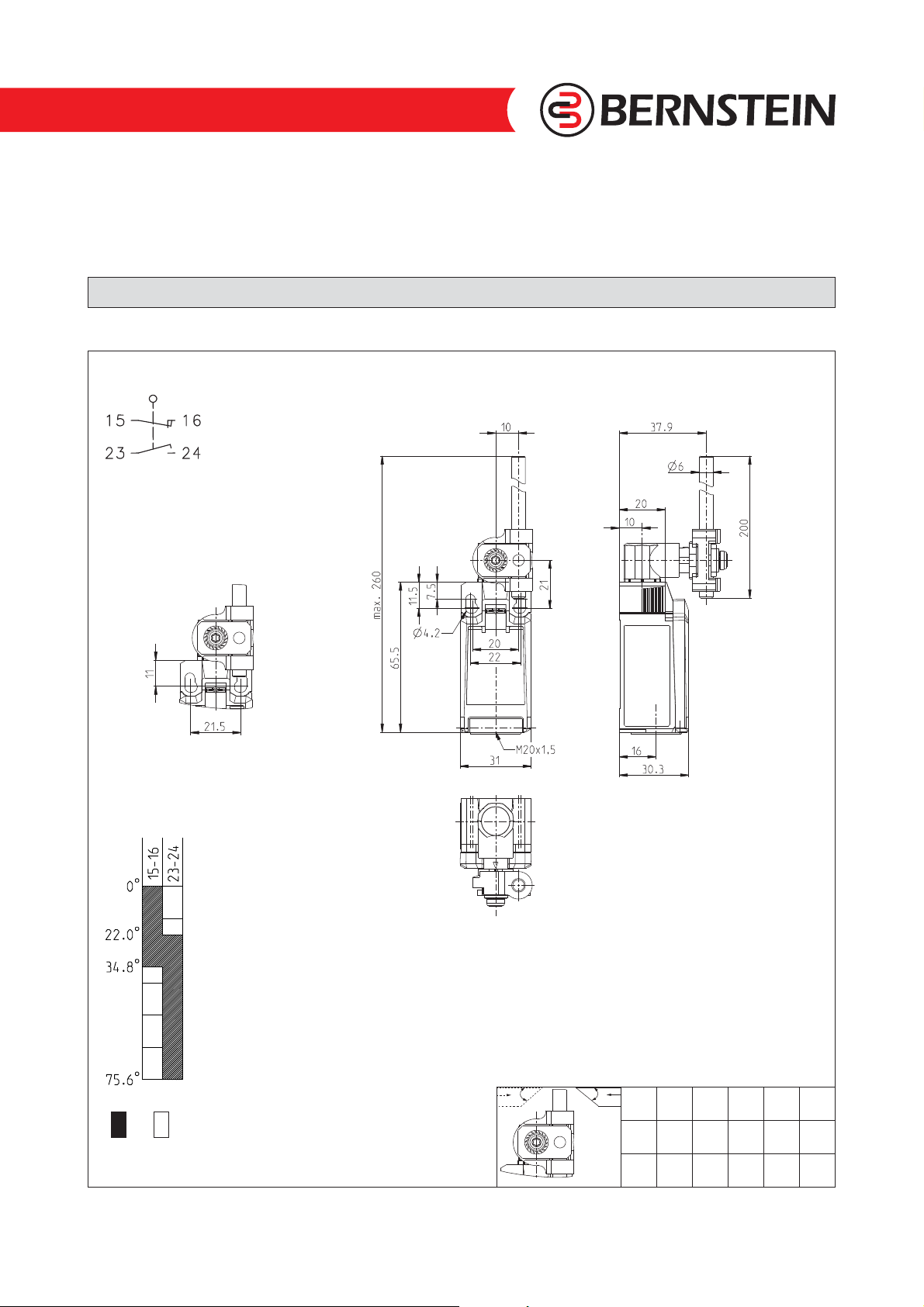
Plastic bodied limit switch
S
eries IN65
Description IN65-UV1 AHDM Article number 6083000306
Operating symbol
Fixed positioning with
e.g. fixing screw M5
according to the standard
DINENISO4762.
Operating diagram
Tolerance:
Operating point ± 3,5 °;
Operating force ± 10 %
ON OFF
Technical modifications and errors excepted.
The technical datasheet corresponds to the technical state as of 2018-01-25 and will not be removed in case of changes.
Page 1 of 3
B
A
m/s 0,1 0,5 1 2 5
A 45° 45° 45° 40° 30°
B 45° 45° 45° 40° 30°
6083000306 / 2058-18
Page 2
Technical Data
Electrical Data
Rated insulation voltage U
Rated impulse withstand voltage U
Rated operational voltage U
Rated supply frequency AC 50 / 60 Hz
Overvoltage category II acc. EN 60947-1 annex H table H1
Conv. thermal current I
Minimum current 1 mA
Reliability acc. EN 60947-5-4 @ 24 V DC, 10 mA, 1 mA, U
Utilization category
Short-circuit protective device Fuse 4 A gG
Rated conditional short-circuit current 400 A
Max. contact resistance 25 mOhm (unused)
Electrical life on request
Mechanical data
Enclosure Thermoplastic, glass fibre reinforced (UL 94-V0)
Cover Thermoplastic, glass fibre reinforced (UL 94-V0)
Actuator Metal wire Ø6 mm / lever in 15 ° increments adjustable
Actuating force F
Operating temperature -30 °C ... +75 °C
Storage temperature -40 °C ... +80 °C
Protection type IP66 / IP67 acc. EN 60529
Pollution degree (built-in switch) 3
Contact material silver
Device Class (built-in switch) Category E (MC3+CC2+SC1) acc. EN 60947-1 annex Q
Contact type 1 N.C., 1 N.O. (Form Zb)
Isolating distance 4 mm (2x2 mm)
Operating rate V 0,06 m/min ≤ V ≤ 30 m/min
Bounce duration ms The value depends on the operating rate.
Switchover time ms The value depends on the operating rate.
Switching frequency ≤ 60 / min.
Mechanical life 10 x 10
Mission time ≤20 years
Connection 4 screw connections (M3)
Conductor cross-sections Solid or Litz wire with ferrules 0,34 mm² - 1,5 mm²; AWG 22-16
Cable entrance 1 x M20 x1,5
Weight ≈ 0,09 kg
Installation position operator definable
400 V
i
4 kV
imp
240 V AC / 24 V DC
e
5 A
the
AC 15, U
DC 13, Ue/Ie 24 V / 4 A
10 N ≤ FB ≤ 30 N
B
240 V / 3 A
e/Ie
6
operating cycles
2,4 V DC
kd
Actuation
The actuating device is preferably started from 2 sides.
By lifting the clamp the actuation assembly can be rotated in 45° increments such that 16 actuation directions are possible.
The actuation assembly is to be again fastened to the housing by lowering the clamp.
Technical modifications and errors excepted.
The technical datasheet corresponds to the technical state as of 2018-01-25 and will not be removed in case of changes.
Page 2 of 3
6083000306 / 2058-18
Page 3

Technical Data
Standards
EU Conformity
Approvals
VDE 0660 T100, DIN EN 60947-1, IEC 60947-1
VDE 0660 T200, DIN EN 60947-5-1, IEC 60947-5-1
VDE 0660 T211, DIN EN 60947-5-4, IEC 60947-5-4
UL 60947-1, CAN/CSA-22.2 No. 60947-1-13
UL 60947-5-1, CAN/CSA-C22.2 No. 60947-5-1-14
UL 508
acc. to directive 2014/35/EU (Low-Voltage-Directive)
DGUV (AC 15, Ue/Ie 240 V / 1,5 A; DC 13, Ue/Ie 24 V / 1,5 A)
CCC (AC 15, U
CSAUS B300, 240Vac 1.5A G.P., 24Vdc 1.5A R. Enclosure Type 4X
C
240 V / 1,5 A; DC 13, Ue/Ie 24 V / 1,5 A)
e/Ie
TÜV
Notes
The degree of protection (IP code) specified applies solely to a property closed cover and the use of an equivalent cable gland
with adequate cable.
Technical modifications and errors excepted.
The technical datasheet corresponds to the technical state as of 2018-01-25 and will not be removed in case of changes.
Page 3 of 3
6083000306 / 2058-18
 Loading...