

Page 1
Technical Data
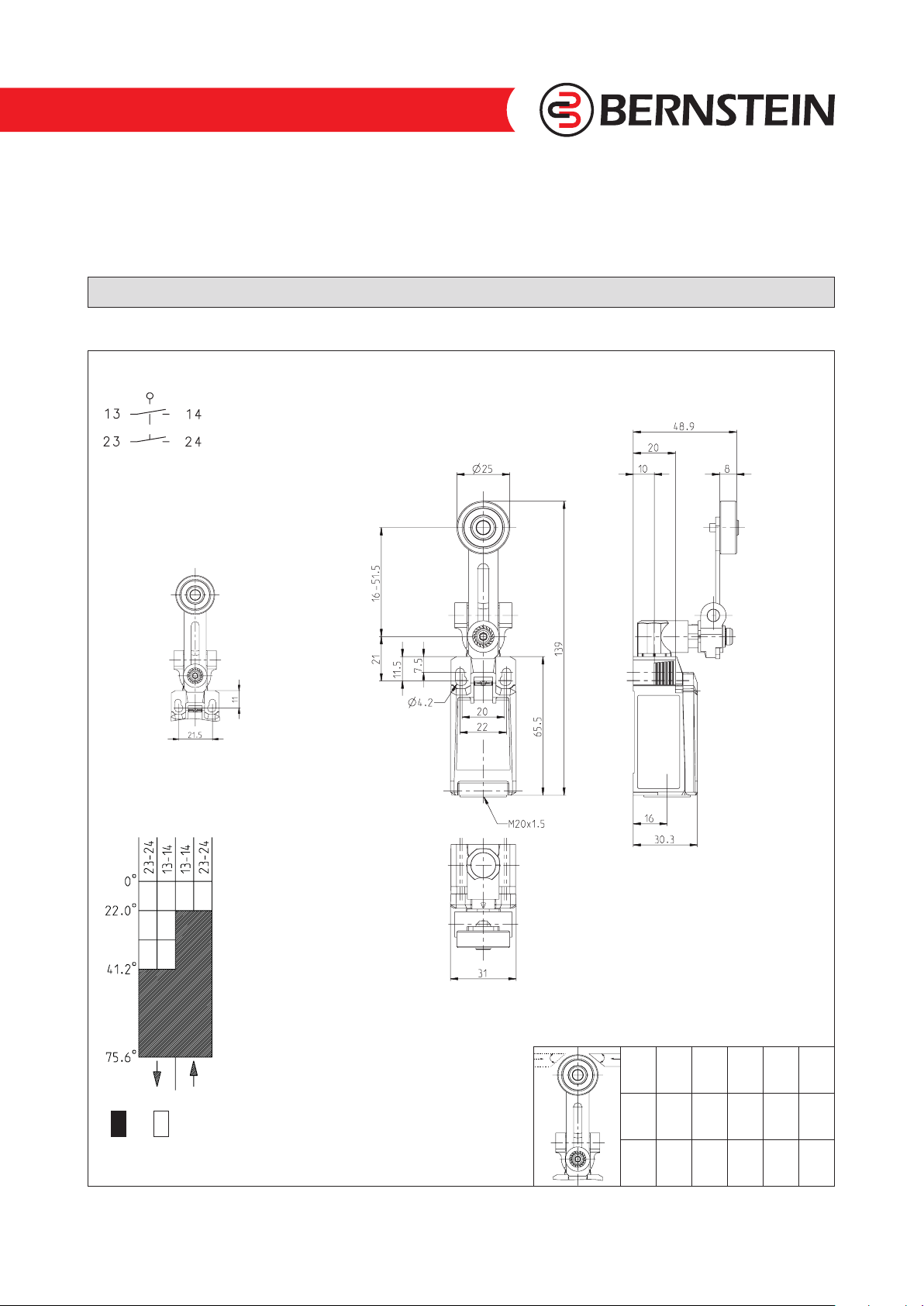
Plastic bodied limit switch
Series IN65
Description IN65-SE2 AVK Article number 6083000288
Operating symbol
Fixed positioning with
e.g. fixing screw M5
according to the standard
DINENISO4762.
Operating diagram
B
A
Tolerance:
Operating point ± 3,5 °;
Direct opening action + 3,5 °
ON OFF
Technical modifications and errors excepted.
The technical datasheet corresponds to the technical state as of 2017-11-28 and will not be removed in case of changes.
Operating force ± 10 %
Page 1 of 3
m/s 0,1 0,5 1 2 5
A 45° 45° 45° 40° 30°
B 45° 45° 45° 40° 30°
6083000288 / 2404-17
Page 2
Technical Data
Electrical Data
Rated insulation voltage U
Rated impulse withstand voltage U
Rated operational voltage U
Rated supply frequency AC 50 / 60 Hz
Overvoltage category II acc. EN 60947-1 annex H table H1
Conv. thermal current I
Minimum current 1 mA
Reliability acc. EN 60947-5-4 @ 24 V DC, 10 mA, 1 mA, U
Utilization category
Short-circuit protective device Fuse 4 A gG
Rated conditional short-circuit current 400 A
Max. contact resistance 25 mOhm (unused)
Electrical life on request
Mechanical data
Enclosure Thermoplastic, glass fibre reinforced (UL 94-V0)
Cover Thermoplastic, glass fibre reinforced (UL 94-V0)
Actuator Metal lever with plastic roller / lever in 15 ° increments adjustable
Actuating force F
Operating temperature -30 °C ... +75 °C
Storage temperature -40 °C ... +80 °C
Protection type IP66 / IP67 acc. EN 60529
Pollution degree (built-in switch) 3
Contact material silver
Device Class (built-in switch) Category E (MC3+CC2+SC1) acc. EN 60947-1 annex Q
Contact type 2 N.O. (Form Zb)
Operating rate V 0,06 m/min ≤ V ≤ 30 m/min
Bounce duration ms The value depends on the operating rate.
Switchover time ms The value depends on the operating rate.
Switching frequency ≤ 60 / min.
Mechanical life 10 x 10
Mission time ≤20 years
Connection 4 screw connections (M3)
Conductor cross-sections Solid or Litz wire with ferrules 0,34 mm² - 1,5 mm²; AWG 22-16
Cable entrance 1 x M20 x1,5
Weight ≈ 0,09 kg
Installation position operator definable
400 V
i
4 kV
imp
240 V AC / 24 V DC
e
5 A
the
AC 15, U
DC 13, Ue/Ie 24 V / 4 A
10 N ≤ FB ≤ 30 N
B
240 V / 3 A
e/Ie
6
operating cycles
2,4 V DC
kd
Actuation
The actuating device is preferably started from 2 sides.
By lifting the clamp the actuation assembly can be rotated in 45° increments such that 16 actuation directions are possible.
The actuation assembly is to be again fastened to the housing by lowering the clamp.
Page 2 of 3
6083000288 / 2404-17
Technical modifications and errors excepted.
The technical datasheet corresponds to the technical state as of 2017-11-28 and will not be removed in case of changes.
Page 3

Technical Data
ID for safety engineering
B10d N.C. 20 x 10
B10d N.O. 1 x 10
Standards
VDE 0660 T100, DIN EN 60947-1, IEC 60947-1
VDE 0660 T200, DIN EN 60947-5-1, IEC 60947-5-1
VDE 0660 T211, DIN EN 60947-5-4, IEC 60947-5-4
UL 60947-1, CAN/CSA-22.2 No. 60947-1-13
UL 60947-5-1, CAN/CSA-C22.2 No. 60947-5-1-14
DIN EN ISO 13849-1
DIN EN ISO 13849-2
UL 508
EU Conformity
acc. to directive 2014/35/EU (Low-Voltage-Directive)
6
cycles (check acc. to DIN EN 60947-5-1)
6
cycles (contact with reduced power for consumers with resistive load)
Approvals
DGUV (AC 15, U
CCC (AC 15, U
CSAUS B300, 240Vac 1.5A G.P., 24Vdc 1.5A R. Enclosure Type 4X
C
240 V / 1,5 A; DC 13, Ue/Ie 24 V / 1,5 A)
e/Ie
240 V / 1,5 A; DC 13, Ue/Ie 24 V / 1,5 A)
e/Ie
TÜV
Notes
The degree of protection (IP code) specified applies solely to a property closed cover and the use of an equivalent cable gland
with adequate cable.
Technical modifications and errors excepted.
The technical datasheet corresponds to the technical state as of 2017-11-28 and will not be removed in case of changes.
Page 3 of 3
6083000288 / 2404-17
 Loading...