


EXPRESS DUAL 4000DX
Please read this manual carefully before using the Express Dual 4000DX.
This manual should be kept in a safe place so that it can be used for future reference.
Touch Screen Model
User’s Guide &
Instruction Manual
EXPRESS DUAL 4000DX

EXPRESS DUAL 4000DX
© Bernhard and Company Limited
NOTES
.....................................................................................................................................................................................................................................................................
.....................................................................................................................................................................................................................................................................
.....................................................................................................................................................................................................................................................................
.....................................................................................................................................................................................................................................................................
.....................................................................................................................................................................................................................................................................
.....................................................................................................................................................................................................................................................................
.....................................................................................................................................................................................................................................................................
.....................................................................................................................................................................................................................................................................
.....................................................................................................................................................................................................................................................................
.....................................................................................................................................................................................................................................................................
.....................................................................................................................................................................................................................................................................
.....................................................................................................................................................................................................................................................................
.....................................................................................................................................................................................................................................................................
.....................................................................................................................................................................................................................................................................
.....................................................................................................................................................................................................................................................................
.....................................................................................................................................................................................................................................................................
.....................................................................................................................................................................................................................................................................
.....................................................................................................................................................................................................................................................................
.....................................................................................................................................................................................................................................................................
.....................................................................................................................................................................................................................................................................
.....................................................................................................................................................................................................................................................................
.....................................................................................................................................................................................................................................................................
.....................................................................................................................................................................................................................................................................
.....................................................................................................................................................................................................................................................................
.....................................................................................................................................................................................................................................................................
.....................................................................................................................................................................................................................................................................

EXPRESS DUAL 4000DX
© Bernhard and Company Limited
EXPRESS DUAL
BERNHARD & CO. LIMI TED
Bilton Road • Rugby • England • CV22 7DT
Tel +44 1788 811600 • Fax +44 1788 812640
Email: i n fo@bernhard.co.uk
USA Toll Free 1-888 GRIND IT
(
1-888 474 6348
)
ED4000DX Precison Reel/Cylinder Grinder
Welcome to the Bernhard Express Dual 4000DX. If cared for and operated
correctly this machine will give you years of good service.
This manual will enable you to obtain the best results from your Express Dual so
please read it thoroughly before using your machine.
If you have any service or operational issues please contact your distributor or
phone our technical support hotline
Technical Helpline (USA only) 1-888 474 6348
Rest of World: UK Head Ofce, England (+44) 1788 811600
Email: support@bernhard.co.uk
Technical FAQs can be found on our web site: www.b
ernhard.co.uk
When ordering spare parts please quote the machine type and serial number.
THE MANUFACTURERS ACCEPT NO RESPONSIBILITY FOR ANY SITUATION ARISING FROM THE
FITTING AND/OR USE OF NON-ORIGINAL SPARE PARTS.
Contents
Identication of Pictograms 3
Safety 5
Installation 6
Identication of Tools and Equipment 8
Understanding the Machine 9
In Frame Grinding 11
Electrical Fault Finding 21
Maintenance 23
Part Lists and Exploded Diagrams 29
Lift Table Instructions 48
Quick Start Guide 58
ED400 0DX Touchscreen – 1003 .4/ENG/2017RB
Please quote this serial number on all
correspondence:
Serial #:

© Bernhard and Company Limited
4
EXPRESS DUAL 4000DX
BEWARE! HIGH VOLTAGE
1. Identication of Pictograms
MAXIMUM LIFT PLATFORM
LOAD - 250 KG (550 LBS)
BEWARE!
TRAPPING FEET OR OTHER OBJECTS
WHEN LOWERING LIFT PLATFORM
MAXIMUM GRINDSTONE
DIAMETER 150mm
MAXIMUM SPEED 4000 Rev/Min
RUNS AT 2200 Rev/Min
BEWARE!
MOVING GRINDSTONE AND SHAFT
REEL ROTATING AT BETWEEN
147 AND 255 Rev/Min
TOTAL WEIGHT OF MACHINE (KG)

© Bernhard and Company Limited
5
EXPRESS DUAL 4000DX
WEAR EYE, EAR AND BREATHING
PROTECTION
1. Identication of Pictograms
(Continued)
POINTS FOR ATTACHING
LIFTING EYES
BEWARE!
MOVING COMPONENTS KEEP HANDS
AND OTHER OBJECTS CLEAR
GRINDSTONE START CONTROL
REEL START CONTROL
STOP CONTROL
TRAVERSE START CONTROL
ENGAGE / DISENGAGE (INCREASE /
REDUCE) GRINDSTONE FEED

© Bernhard and Company Limited
6
EXPRESS DUAL 4000DX
2.1 This machine is designed and manufactured ONLY for grinding lawn mower reels, rollers,
groomers and verticut units, and MUST NOT be used for any other purpose.
2.2 This machine should be installed, operated and maintained by competent personnel who
have received adequate training.
2.3 Before carrying out any work on the machine, other than grinding, ALWAYS SWITCH OFF
the main electrical supply, or remove the power lead from its socket.
2.4 ALWAYS operate the machine with the guards in position.
2.5 NOISE - Owing to the widely varying conditions of use, noise emissions may vary
considerably. There may be occasions when the safe noise level may be exceeded (see
note on noise emission). In this case adequate ear protection MUST be worn.
2.6 NEVER t or use a grinding wheel (or other spares) other than those supplied specically
for use on the EXPRESS DUAL (Warranty will be invalidated).
2.7 NEVER t or use a grinding wheel which has been dropped or subjected to any other form
of abuse.
NOTE: Grinding wheels should be tted O N LY by competent, trained personnel.
2.8 NEVER leave rags or tools on the machine or wear any loose clothing or other articles
which could be caught in moving components.
2.9 NEVER allow any combustible materials to be placed on or around the machine.
2.10 ALWAYS ensure that all parts of the cutting unit being ground are securely xed.
2.11 ALWAYS ensure that all electrical connections are sound and all cables are safely routed.
2.12 ALWAYS carry out cleaning and maintenance of the machine as instructed in this manual
(Refer to safety note 2.3).
2.13 STAY ALERT. Watch what you are doing. NEVER operate the machine when tired, or
under the inuence of drugs or alcohol.
If a lift table is tted NEVER attempt to lift in excess of the rated capacity, and always
ensure that the area is clear before lowering the load.
2. Safety

© Bernhard and Company Limited
7
EXPRESS DUAL 4000DX
3. Set Up and Installation
Fig: 3.2
3.1 Handling
If the machine is crated, it can be moved by a suitable fork lift truck or pallet truck under
the pallet (skid). Once the lid and sides of the crate are removed, a fork lift truck may be
used under the lifting members of the machine chassis.
The machine can be lifted off the pallet using suitable lifting tackle through 4 lifting eyes
(provided) tted at the points indicated on the top corners of the machine.
The total weight of the machine is indicated on the machine plate and also at the front of
this manual.
3.2 Location
The machine should be located in a well lit environment with adequate headroom. For
ideal operation, the machine should be accessible from the front, rear and at least one
side, with clearance around it as indicated in the sketch (Fig. 3.2).
3.3 Leveling
The machines should, ideally, be placed on a solid level oor, and this should be checked
by placing a spirit level on the table. Check the level in both directions. Steel shims should
be placed under the feet as necessary to ensure that the machine is rm and level. Bolt
holes are provided in the feet which can be used for xing down if required.
NOTE Ensure that the packing under the feet is correct before tightening the bolts, otherwise
twisting of the frame may occur.
1.5m (5 ft)
1.5m (5 ft)
ENSURE ADEQUATE SPACE FOR
LOADING UNITS AND FOR A LIFT
TABLE (IF FITTED)
FRONT OF MACHINE

© Bernhard and Company Limited
8
EXPRESS DUAL 4000DX
3.4 Electrical Supply
USE A QUALIFIED ELECTRICIAN
The EXPRESS DUAL is supplied with a .75 kW (1 HP) single phase main (grind) motor
plus 2 fractional HP motors, for spin and traverse.
Power connection to the machine is via plug and socket termination of the lead supplied.
Connection is at the rear of the main electrical control box on the right hand end of the
machine.
Ensure that any cable or conduit run to the machine does not constitute a hazard to the
operator or other personnel.
Machine should be connected to the supply via a 20A breaker.
The top of the reel and the top of the grinding wheel should both move away from the
front of the machine (i.e. both rotate clockwise when viewed from right hand end of the
machine). In this way, the reel and grinding wheel are moving in OPPOSITE DIRECTIONS
at the point of contact.
3.5 Preparation
If the machine has been
received in a crate, the handles
on the control wheels should be
removed from the underneath of
the control wheels and retted to
the top (see Fig. 3.5).
It is important that the protective
lm on the main shaft is
removed prior to using the
machine. This can be done
using a WD40® or similar
product (not gas/petrol) and then
drying the shaft with a clean, dry
cloth so that the grinding wheel
assembly moves freely along the
whole length of the shaft.
A spray lubricant, such as WD40®, should be applied to all bare metal surfaces and
moving parts; this includes the reversing bar and the shafts (along which the fork assembly
traverse, but NOT THE MAINSHAFT).
The mainshaft should be washed down as instructed in the maintenance section of this
manual. The feed control screws are normally coated with Molycote®, and may be washed
down with WD40® if required and recoated with Molycote® (or similar anti friction coating)
when dry.
Fig: 3.5
3. Installation (Continued)

© Bernhard and Company Limited
9
EXPRESS DUAL 4000DX
4. Indentication of Tools and Equipment
The items below may not necessarily be included since the tools and equipment
supplied will vary according to the machine specication.
4.1 Express Dual 4000 and 4000DX (see illustrated parts list).
A9502 Adjustable Mounting Bracket Set (Fitted) ........................1
A6505 Grind Stone (Fitted) ..................................................................1
A6737 Diamond Dresser (In Spin Drive Support) .......................1
A2719 Grinding Wheel Wrench ..........................................................1
A6342 Pressure Plate ............................................................................1
A4095 Plain Drive Rod Short ..............................................................1
A4134 Square Drive Rod Short (Fitted To Cable Drive) ...........1
A4066 Long Ball Handled Allen Key .................................................1
A2720 Large Hex Key ............................................................................1
A2706 3/16 T Handled Allen Key .......................................................1
A4097 Plain Shaft Driver ......................................................................1
A4063 Large Two Pin Sprocket Driver .............................................1
A4133 Drive Kit - Female Splines......................................................1
A9535 Adj. Sprocket Driver Complete .............................................1
A9534 Eccentric Pin For Adj Sprocket Driver ...............................3
A2722 Molycote Paste ...........................................................................1
A6847 Molycote Brush...........................................................................1
A4087 Multix Channels .......................................................................1
A2712 8mm Allen Key ...........................................................................1
A8786 Pack of Spare Fuses ................................................................1
A2708 3mm Allen Key ...........................................................................1
A3306 22mm 1/2 Drive Socket ...........................................................1
A6603 Guarantee Certicate ..............................................................1
A6615 Operating Instructions .............................................................1

© Bernhard and Company Limited
10
EXPRESS DUAL 4000DX
5. Understanding the Machine
5.1 General Principles
The EXPRESS DUAL is designed to grind reels completely assembled, or as a separate
“loose” reel. A Loose Reel Kit (Available as an optional extra, at additional cost) is required
for this operation.
The basic principle of the EXPRESS DUAL is to grind mowers in exactly the same
conditions that they mow in. The grinding wheel takes the place of the grass, striking the
reel in relatively close proximity to that found in the mowing position.
5.2 Basic Requirements
It is important that grinding the cutting unit, when it remains completely assembled, takes
place under the following conditions:
5.2.1 The reel bearings MUST be in good condition, adjusted correctly and if the roller is to be
located on the roller mounting brackets or the multix brackets, the roller bearings MUST
also be in good condition.
5.2.2 The bedknife must be ground separately on a machine, such as the ANGLEMASTER
bedknife grinder which can guarantee that the blade will be perfectly STRAIGHT and at
whilst mounted on the bedbar.
During the reel grinding process, it is advisable that the bedknife/bedbar assembly is
replaced in the unit after having been ground. On many units the bedknife/bedbar is an
integral part of the frame and contributes to its strength and rigidity.
5.2.3 The reel or bedknife must be adjusted away from one another to allow free rotation (There
should be no reel to bedknife contact!).
5.2.4 It is essential that all work to be carried out on the mowing unit (all mower repairs
– bearings, seals, roller work, etc.) has been completed prior to grinding the reel. The last
operation of all, apart from nal setting reel to bedknife, is the actual grinding of the reel
in-frame.
It is essential that the unit is held totally rm during the grinding process. When in frame
grinding, the front of the unit must be held rmly in the multix brackets or on the front
roller brackets.
5.2.5 It is essential that the unit is held totally rm during the grinding process. When in frame
grinding, the front of the unit must be held rmly in the multix brackets or on the front
roller brackets.
The rear of the unit will be held by the radiused pressure bar at the rear of the grinder.

© Bernhard and Company Limited
11
EXPRESS DUAL 4000DX
5. Understanding the Machine (Continued)
5.3 Machine Functions
The EXPRESS DUAL has separate motors driving the different functions of the machine,
all are turned on and off from the control panel in ‘manual’ mode or by the machine
program in ‘auto’ mode. These functions are as follows:
5.3.1 Traverse
This motor and the accompanying drive mechanism controls the automatic movement of
the grinding wheel along the mainshaft.
5.3.2 Reel/Spin drive
This motor drives the reel through a exible shaft driving from a drive mechanism under
the table. It is a three phase motor controlled by an inverter for varying output speed.
5.3.3 Grinding Wheel
A motor situated under the table, drives the mainshaft and grinding wheel at around 2200
rpm.
5.3.4 Stop
Pressing the stop button shuts off all motors and locks into the “off” position. None of the
start buttons will operate until the stop button has been unlocked by twisting the knob
counter-clockwise to release it (and the m/c control error warning has been reset).
NOTE The machine must NOT be stopped when there is contact between the reel and grinding
wheel, except in cases of emergency.
5.3.5 Reset Button (see also Electrical Fault Finding section)
If the main motor is subject to a voltage drop or overloading, the current being drawn
will rise and a safety device will automatically shut the grinder off. The overload trip
device (thermal overload contactor) is attached to the main motor contactor in the main
electrical control box which is located within the safety guard on the right hand side of the
machine.(looking from the front). The (red) reset button is on this overload.
The trip setting will vary with the electrical specication of each machine and is normally
set to the full load current of the motor. If the overload trip has shut off the grinder it can be
reset by pushing the reset button after a few minutes delay. This will allow the grinder to be
re started.
NOTE The overload is variable and should be adjusted, if required, as indicated in the appropriate
service bulletin.
Other motor, VSD inverter (reel spin speed control), and other electrical devices are
protected by individual fuses located on the electrical control panel accessible via key
entry to the enclosure on the right hand side of the guard.

© Bernhard and Company Limited
12
EXPRESS DUAL 4000DX
6.1.1 Mower Preparation
Units of up to 36” long can be ground
in frame, this includes most machines
including Greens mowers and Fairway
units. In order to spin / drive the reel,
one end of the reel shaft drive must be
exposed. This will require the removal
of the hydraulic motor, the chain / belt
or cover depending on which type
of unit is being ground. This should
be done before the mower is on the
grinder (see example Fig. 6.1).
Ensure that the mower is clean and
that both reel and roller bearings are
in good condition. Also ensure that
the bedknife has been sharpened, if
necessary, and replaced with a small
amount of clearance between it and the reel.
FOLLOW THE ILLUSTRATED INSTRUCTIONS IN THE QUICK START
GUIDE AT THE END OF THIS MANUAL
6.1. 2 FOLLOW THE SCREEN PROMPTS
Press Auto icon button to progress from the welcome screen to automatic mode
– display advances to next screen
Screen prompts to:
Ensure traverse is not engaged
To mount mower
To engage clamp
6.1.3 Unscrew the traverse engagement screw until it is released from the traverse chain so that
fork/grindstone can be traversed manually along the mainshaft.
6. In-frame Grinding
Fi g: 6 .1

© Bernhard and Company Limited
13
EXPRESS DUAL 4000DX
6. In-frame Grinding (Continued)
6.2. Mounting Mower
The mainshaft / Grinding stone should be wound down to its lowest position and the unit
placed on the table. The unit should then be carefully moved towards the multix brackets
or front roller brackets, which can be adjusted in any direction to allow the unit to be xed
in such a position that the grinding wheel can be raised towards the reel without coming
into contact with either the bedknife or the front roller/groomer.
6.3. Clamping
With the mower correctly positioned the radiused pressure bar) is moved forward to rest
on the rear of the mower and locked in position by pressing the key on the operator display
panel on the operator control panel downwards. The operator should release the key as
the pressure bar engages the cutting unit thus retaining pressure on the mower until the
grinding operation is completed. A backing up plate is supplied to protect the rear of the
units and to evenly disperse the force of the pressure bar across the width of the mower
(see Fig. 6.3.1.).
Fi g: 6 .3.1

© Bernhard and Company Limited
14
EXPRESS DUAL 4000DX
To ensure that the correct position for the mower unit has been achieved, both control
wheels (right hand and left hand) should be wound in a clockwise direction so that the
grinding wheel may be placed to contact each end of the reel evenly. If the grinding wheel
touches the bedknife or any part other than the reel, the whole unit must be moved by
adjusting the position of the multix brackets or roller brackets. The exact position required
will be easily seen by looking along the mainshaft from one end of the machine as the
stone is raised to check that the point of contact is in a suitable position (see Figure 6.3.2.)
Rotate hand wheels anti-clockwise to move grinding wheel away from reel. It is important
that the grinding wheel should clear the highest blade along the full length of the reel
before proceeding.
NOTE If the cutting unit has no front roller tted so that the multix brackets are used then, once
the correct position for any particular unit has been nalised a “set up guide” should be
completed and led for future reference so that the identical multix brackets positions can
be used for all subsequent applications on the same type of unit.
6. In-frame Grinding (Continued)
Fig: 6.3.2
Reel
blades
Front Roller position
is adjustable
Grind stone has to contact
reel blades for sharpening
without touching anything else
Adjustable Front
Roller support
Position of
bedknife is
adjustable

© Bernhard and Company Limited
15
EXPRESS DUAL 4000DX
6.4 Linking Up The Reel Drive Unit to the Reel
Machines are supplied with the reel drive motor under the table and a exible drive which
can be attached to either end of the machine do not have to be prepared before the mower
unit is placed on the table, as the complete drive unit can be moved to either side of the
table with a mower unit in place.
6.4.1 Select the attachment with which to drive the reel. If the reel sprocket, gear or pulley
is secured with a nut it may be easier to use a standard socket together with a 1/2”
square end driver. Ensure the nut is tight as the direction of rotation may tend to unscrew
it. Ensure that the drive shaft is through the exible coupling/driver before setting the
machine on the table and that the whole unit is at the correct end of the table.
Alternatively it may be easier to drive directly onto the sprocket using one of the pin or
adjustable type sprocket drivers tted to the plain drive rod.
6.4.2. When the cutting unit is in place and rmly xed into the multix brackets, or front roller
brackets, and the rear clamped with the radiused pressure bar, adjust the drive unit left or
right so that the appropriate drive rod will reach the end of the reel shaft. Tighten unit in
place.
Adjust the height and position, forwards and backwards and up and down, of the cable
drive support so that the shaft is square with the driven end of the reel, and tighten clamps
to hold it in place.
The black lobed hand screw allows the drive head to be moved along the square support
shaft to adjust the height of the drive, while the 5/8” hex headed socket screw allows the
support shaft to be clamped at any desired angle, and also allows the whole assembly to
be moved left or right along the machine bed to engage in the drive mechanism on the
reel.
The drive head of the shaft can also be slid through it’s support for further adjustment or
nal connection/ disconnection of drive.
6.4.3 Tighten the drive rod via the allen screw in the exible coupling onto the at of the drive
shaft.
6. In-frame Grinding (Continued)

© Bernhard and Company Limited
16
EXPRESS DUAL 4000DX
6. In-frame Grinding (Continued)
6.4.4 Moving the exible Shaft
There is a lay shaft socket at both ends of the
machine into which the exible drive can be
engaged as required. The other end of the
exible shaft can be disconnected if required
but this would not generally be necessary as the
bracket and shaft would normally be moved as
an assembly
The exible drive shaft can be detached
from its socket on the end of the machine by
pulling sharply on the shaft, to release it from
a spring loaded ball detent. (Earlier units by
rst removing the spring retainer (R-pin)),
and withdrawing the complete shaft (see Fig.
6.4.2.2.) When replacing the shaft, ensure that
it is properly engaged in the lay shaft socket.
By loosening the socket screw and allowing
the clamp nut, under the table, to twist through
approximately 90 degrees, the whole assembly
can be lifted clear of the table, and moved to the
other side of the mower unit if required.
Press “next” icon on operator display – display advances to next screen.
Fig. 6.4.4.2

© Bernhard and Company Limited
17
EXPRESS DUAL 4000DX
6.5 Actual Grinding
Screen requests size of mower.
6.5.1 Press the relevant icon to select size of mower:
n Smaller units (or Greens)
n n Medium sized units (or Tees / Light
Fairway)
n n n Large units (or Fairway)
Display advances to the next screen.
Screen requests type of grind required.
6.5.2 Press the relevant icon to select type of grind required:
n “touch up” (mower needs little
sharpening, probably part of a regular
sharpening regime)
n n “maintain” (blades need just a little more
material removing to get a good edge) or
n n n “rectify” (damaged blades, or a unit rarely
ground or heavily back-lapped)
Display advances to the next screen.
6.5.3 Screen shows selected answers (grind cycle)
CLOSE GUARD FIRST
Press tick (“accept”) icon if OK. (Grind, Traverse and Reel drive motors start – display
advances to the next screen).
or
Press cross (“reject”) icon if you wish to make an alternative selection (display returns to
size of mower question).
6. In-frame Grinding (Continued)

© Bernhard and Company Limited
18
EXPRESS DUAL 4000DX
6. In-frame Grinding (Continued)
6.5.4 Set up of Traverse
With motors running, the screen prompts: “set grind stone to reel” and
“set traverse limit stops”
Traverse the grinding wheel by hand, using the Traverse Engagement Screw until it is at
the extreme point of desired travel. Ensure that the traverse reversing bar is also moved in
that direction and slide the reversing stop up to the grinding wheel traverse assembly and
tighten. Move the grinding wheel to the opposite end of the desired travel and repeat the
operation ensuring that the reversing bar has also been moved in the opposite direction.
This is critical where the grinding wheel cannot pass beyond the end plates if they protrude
below the maximum diameter of the reel.
NOTE On the EXPRESS DUAL it is not necessary for the whole width of the grinding wheel to
pass the end of the reel and it SHOULD NOT DO SO EVEN IF SPACE PERMITS (see
Fig. 6.5.4).
Ensure that the leading edge
of grinding stone passes the
end of the reel – but clearance
must be maintained between
stone and end frame of unit.
NOTE: The reversing bar will move approximately ½” (13mm) before the direction of travel is
reversed and will allow the grinding wheel to move with it. It is therefore ESSENTIAL that
this is taken into account when setting the maximum point of travel.
Fig: 6.5.4

© Bernhard and Company Limited
19
EXPRESS DUAL 4000DX
6.6.1 With the stone positioned at the left hand end of the reel, place the left hand on the left
hand control wheel and the right hand on the traverse knob, moving the grinding wheel
along the reel by hand using the traverse engagement screw, wind up the left hand control
wheel clockwise until the grinding wheel strikes and sparks gently against the reel.
6.6.2 Unwind a complete turn to move the stone away from the reel.
6.6.3 Move the grinding wheel to the right hand end of the reel and, using the right hand on the
right control wheel, raise the shaft until the reel again can be gently rotates against the top
of the grinding wheel.
6.6.4 Unwind half a turn.
6.6.5 Go back to the left hand end and repeat the process but this time, after contact has been
made, unwind only sufciently to release the contact.
6.6.6 Go back to the right hand end and repeat the process and again release the contact only
slightly.
6.6.7 Repeat this process on the right hand side of the reel, raising the shaft with your right hand
and moving the grinding wheel along with your left hand. Repeat this process until the
contact all along the reel is light, even and parallel.
6.6.8 Screw in traverse knob to engage power traverse.
NOTE: Check auto traverse is changing direction at correct point at each end of its
movement.
6.6.9 Press “next” icon to start grinding cycle
Screen reads “GRINDING”. Pictures on display animate.
Both handwheels will automatically rotate clockwise to apply a parallel cut to the reel.
After a pre-determined number of traverse passes of the stone along the reel a further in
feed will be applied.
According to the program selected a certain number of in feeds / traverse passes will
follow until the cycle is completed. Both handwheels will then rotate counter-clockwise, to
back the stone away from the reel, and all motors will stop.
(Programme will NOT let a reel “spark-out” with factory set programme parameters)
6. In-frame Grinding (Continued)

© Bernhard and Company Limited
20
EXPRESS DUAL 4000DX
6.6.10 Screen reads “PROGRAM COMPLETE
Press “nished” icon if reel is satisfactory
or
Press “re-do” icon if it needs more grinding, to repeat the whole cycle
or
Press “touch-up” icon if reel is almost there but could do with a “touch up” to nish it off.
6.6.11 Press “nished” icon to advance display to the next screen “Grinding completed”-
remove mower from machine”
6.6.12 Press “unlock” icon to undo clamp and remove mower
6.6.13 Press “next” icon to return to the starting screen
6.7 ALTERNATIVES
6.7.1 If “re-do” or “touch up are selected, (close the guard before selection).
After a pause the motors will re-start and the handwheels will return the grindstone to the
position where the grind cycle nished. Further feeds/traverses will follow until the cycle is
completed once more,
6.7.2 At this time the guard can be opened and the condition of the reel checked.
6.7.3 If the blades are sharp enough Press the “nished” icon.
6.7.4 The display will change to “Grinding completed – remove mower from machine”
screen.
6.7.5 If the blades still need some grinding, the “resume” icon can be pressed, after closing
the guard. After a pause the motors will re-start and the handwheels will return the
grindstone to the position where the grind cycle was paused. The cycle will continue to it’s
conclusion.
6. In-frame Grinding (Continued)

© Bernhard and Company Limited
21
EXPRESS DUAL 4000DX
6.8 MANUAL MODE GRINDING
If at welcome screen “Manual Mode” is selected, the Express Dual can be used as with
any other machine in the ED series.
The operator display shows the three motor buttons as:
– Grind
– Spin
– Traverse
In manual mode, pressing one of these icons once will start a motor (icon colour changes
to red). Pressing it a second time will then stop the motor.
Also displayed are two digital, numerical counters, one for each handwheel.
Pressing the Reset key will set these counters to zero.
The clamp is still operated by the “lock” and “unlock” and the vacuum can be “toggled”
on and off using its icon.
For other screen information see QUICK START GUIDE at the back of this manual.
6. In-frame Grinding (Continued)

© Bernhard and Company Limited
22
EXPRESS DUAL 4000DX
USE A QUALIFIED ELECTRICIAN
In the event of any motor not starting, the following procedure should be adopted:
7.1. Check that the EMERGENCY STOP BUTTON on the control panel, immediately below the
HMI screen, is not locked down in STOP position (twist counter-clockwise to release).
7.2 Check fuses – main fuses feeding machine (alongside isolator switch by power connection
to machine) and small fuses on electrical panel (in the enclosure on the right hand side of
the safety guard).
7.3. Check voltage in isolator/junction box (right hand side of machine) coming out of the
isolator switch.
7.4. Check that safety contactor on the main electrical panel is engaged (centre pulled in).
7.5. Check for open circuit on overload, terminals 95 and 96, to determine whether or not main
motor is faulty. If open circuit press red resetting button on overload and re-test.
7.6. To determine that all motor contactors are OK test each one by relative icon button on the
HMI screen (in ‘manual’ mode), they should noticeably pull in. This can be checked by
someone looking in the junction box while the start icons are pressed.
7.7. Trav erse
Check the traverse and reversing contactor function (press screen icon and operate the
reversing bar so that traverse microswitch is activated) If only the traverse contactor is
functioning properly check the microswitch. If this is found to be OK check capacitor if
possible. If neither of these is faulty, then the motor is probably at fault.
7.8. Reel Drive
If the contactor is functioning properly, check the Inverter:
Check the red LED display on the front of the unit. This should be lit and display a value
that reects the reel speed (as a frequency). If it is out, or shows a fault/error code, the
start button, there is an inverter fault.
Disconnect the power to the machine, wait 2 minutes, then re-connect and try again (to
re-set the inverter).
If neither are faulty then the motor is probably at fault.
7.9. Main Motor
If the contactor is functioning correctly, check the load current with an ammeter across
terminals T2 and T3 on thermal overload. If this exceeds full load current indicated on
the motor identication plate then a new motor is needed. If the reading is below full load
current then possibly the overload is set too low.
NOTE Before assuming that there is an electrical fault in any of the systems ensure that the
mechanical drive assemblies attached to a particular motor are moving freely, and have
not got increased resistance due to damage, or the build up of dirt. This can best be done
by detaching the motor drive and ensuring that the mechanism is moving freely.
7. Electrical Fault Finding

© Bernhard and Company Limited
23
EXPRESS DUAL 4000DX
NEW FUSEHOLDERS (ED4000DX)
TO ACCESS FUSE
USE A SCREWDRIVER
TO UNCLIP & PIVOT
THE HOLDER
UPWARDS
NEW
FUSEHOLDERS
Led ILLUMINATES
ONLY WHEN FUSE
USE
SCREWDRIVER TO
OPEN COVER &
ACCESS FUSE
TAKE CARE WHEN
REMOVING FUSE
NOT TO DISPLACE
METAL CONTACTS

© Bernhard and Company Limited
24
EXPRESS DUAL 4000DX
8. Maintenance
8.1 Grinding Wheel Replacement
NOTE Grinding wheels should always be tted by competent, trained personnel.
8.1.1 The grinding wheel (stone) is held on the carrier by a nut which should be loosened, using
the “C” Spanner provided, before the assembly is removed from the mainshaft.
8.1.2 Slide the grinding wheel to the left hand side of the machine (viewed from the operator
position).
8.1.3 Release the 2 allen screws in the bearing ange ring on the left hand end of the main
shaft.
8.1.4 Raise the mainshaft to its maximum height, maintaining the shaft as horizontal as possible
until the right hand side comes up against the stop in the feed column and the left hand
side is at its maximum height. At this point the fork will drop away from the grinding wheel
assembly.
8.1.5 Place a wooden block under the mainshaft to the right hand side of the grinding wheel
assembly, bridging the front bed and front channel to take the weight of the mainshaft
when the side arm is removed (see Fig. 8.1.5).
Fi g: 8 .1. 5

© Bernhard and Company Limited
25
EXPRESS DUAL 4000DX
8. Maintenance (Continued)
8.1.6 USING THE “C” SPANNER PROVIDED, loosen the retaining nut. (If not a worn, to be
discarded, stone can be held in a vice whilst the nut is loosened. NEVER hold the sleeve
and nut in a vice)
8.1.7 Remove the circlip retaining the left hand side arm to the rear shaft. The side arm can now
be removed from the machine.
8.1.8 The grinding wheel and sleeve can now be withdrawn. (Note into which keyway of the
mainshaft the assembly was tted.) Remove the retaining nut and the old wheel. Clean
sleeve and nut thoroughly.
8.1.9 Fit the new grinding wheel and replace the collar, ensuring that all mating services are
clean and undamaged.
8.1.10 Ensure that the mainshaft and sleeve are perfectly clean and dry. Reassemble in the
reverse order ensuring that when you replace the grinding wheel assembly onto the
mainshaft, the nut is on the LEFT HAND side when viewed from the operator’s position
(Tighten nut whilst assembly is on the mainshaft). Use the opposite keyway from
which the assembly was removed.
NOTE Be careful to guide the assembly into the fork when lowering the mainshaft. Make sure that
the left hand side arm is centered in the channel.
8.1.12 Loosen the small allen key in the reel drive support block, pull the diamond dresser out a
short way and re tighten the screw.
8.1.13 With the stone NOT running, bring the mainshaft (and grindstone) up horizontally.
Manually traverse the ‘stone past the diamond, making a light scratch, to conrm that the
shaft is horizontal.
8.1.14 Move the stone just clear of the dresser then start the grind motor.
8.1.15 Bring up the shaft equally on each side and manually traverse the ‘stone across the
dresser.
8.1.16 Switch on and engage the auto traverse with the stops set so that the stone completely
passes the dresser back and forth.
8.1.17 Apply more feed as necessary to true the stone.
NOTE Dressing in this way should be carried out periodically to keep the grindstone clean and
true BUT remove only the minimum material off the stone to keep long service.

© Bernhard and Company Limited
26
EXPRESS DUAL 4000DX
8. Maintenance (Continued)
NOTE When tting a new sleeve and nut, it may appear that the assembly is too tight to t onto
the mainshaft of the Express Dual.
This is because all replacement sleeve and nut assemblies are shipped with the drive key
left very slightly oversize to allow for varying degrees of wear in the mainshaft keyway.
(The key is ‘glued’ into the sleeve NOT welded).
The key needs to be “tted” to the mainshaft. This may entail ling a small amount of
material from both the depth of the key and the sides. Remove only a very small amount of
material at a time, then check the t, until the sleeve and nut assembly slides freely along
the length of the mainshaft without any play between key and keyway.
REMEMBER
The mainshaft keyway will be less worn at the ends of the shaft than where the normal
traverse of the grindstone occurs, do not remove too much metal from the key.
NEVER grip the sleeve and nut assembly in a vice. Fully tighten the nut when the
assembly is tted to the mainshaft.
Sleeve
Key
Mainshaft
2nd Key
Remove minimal material from
sides and bottom of key

© Bernhard and Company Limited
27
EXPRESS DUAL 4000DX
8. Maintenance (Continued)
8.2 Cleaning and Lubrication
NOTE: IF THESE CLEANING AND MAINTENANCE PROCEDURES ARE NOT
FOLLOWED THE MACHINE WARRANTY WILL BE INVALIDATED.
8.2.1 Daily
Before use:
Mainshaft –after thoroughly cleaning, dry and ensure that no oil remains at all.
It is essential that the grinding wheel sleeve and nut can be moved freely along the entire
length of the mainshaft at all times.
After use:
Wipe off any deposits of grinding dust with a dry cloth or brush ensuring the keyways
are kept clean. Using a ne spray oil, such as WD40® or Bernhard ‘Fine clean/lube’,
spray the whole shaft. Use an excess of uid sprayed in one place and slide the grinding
wheel assembly backwards and forwards over that area in order to wash out thoroughly
the inside of the sleeve. This will remove any build up of material and ensure the free
movement of the assembly along the shaft.
Leave a ne lm of WD40® / ‘Fine clean/lube’ spray in place overnight but ensure that
Shaft is wiped DRY before any grinding is carried out.
Over a weekend, or longer periods where machine may not be used, spray main and other
nearing shafts with Bernhard ‘Protective oil lm’ but clean with WD40® / ‘Fine clean/lube’
and dry before any grinding is carried out.
Occasionally lubricate the contact areas of the fork driver (with the sleeve and nut)
with “MOLYCOTE”® (Molybdenum Disulphide), this will impregnate the surface. Excess
lubricant / propellant should be wiped off again after a short time.
NOTE Never leave any oil or grease on the mainshaft.
8.2.2 Weekly
Spray WD40® / ‘Fine clean/lube’ or equivalent onto all moving parts (the mainshaft must
be completely dried before any grinding is carried out). This includes the threads under the
feed column handwheels, the reversing bar and the shafts on which the fork and pickup
assembly run. The majority of bearings are either oil impregnated or are ball races and,
apart from those mounted in special sealed housings or tted with grease nipples, require
the occasional drop of oil.
Check the vacuum collector beneath the grindstone and the container and lter of the
vacuum unit beneath the machine (accessible by removing the panel on the back of the lift
table). Clean/empty as necessary.
Examine belts for wear and tension. DO NOT OVER-TIGHTEN. Examine fork assembly
for wear – some slight discolouration may occur, this is not a problem.

© Bernhard and Company Limited
28
EXPRESS DUAL 4000DX
8. Maintenance (Continued)
8.2.3 6 Monthly
Chain and idler sprocket require cleaning and oiling.
8.2.4 Yearl y
Mainshaft bearings are pre-packed with grease. IF grease nipples are tted ONLY 1
SMALL SHOT of grease should be applied annualy.
These bearings run warm/hot, that is OK. Extra grease will not reduce the temperature,
more likely the reverse, the seals and subsequently the bearings may fail prematurely.
Replace the vacuum lter (if not already done following routine examination).

© Bernhard and Company Limited
29
EXPRESS DUAL 4000DX
9. Parts List
Page
MAIN FRAME 9.1
FEED ADJUSTMENT 9.2
MAINSHAFT MOUNTING AND MAIN MOTOR DRIVE 9.3
TRAVERSE ASSEMBLY 9.4
REEL DRIVE 9.5
CLAMP ASSEMBLY 9.6
MULTI-FIX BRACKET ASSEMBLY 9.7
GUARD 9.8
CONTROL BOX 9.9
ELECTRICAL CABINET 9.10
LIFT TABLE 9.11

© Bernhard and Company Limited
30
EXPRESS DUAL 4000DX
9.1 MAIN FRAME
__________________________________________________________
1 Frame ...................................................................................... 1 A4050
2 Top Plate .................................................................................1 A4142
3 Upper Front Skir t ..................................................................... 1 A6352
4 Rear Skirt ................................................................................1 A6397
(not required if Lift Table tted)
5 Front Skirt ................................................................................ 1 A6328
6 Drawer ..................................................................................... 2 A6321
7 Drawer Handle ........................................................................2 A6110
8 Dust Tray .................................................................................1 A6323
9 Dust Tray Handle ..................................................................... 2 A6111
10 Drawer Runner (Pad) ..............................................................4 A6 742
11 Drawer Runner (Drawer) ......................................................... 4 A6741
12 M5 x 10 Button Socket Screw ................................................. 8 A5129
9. Parts List (Continued)
Ref # Name of Part Qty. Part #

© Bernhard and Company Limited
31
EXPRESS DUAL 4000DX
7
6
5
4
3
2
1
8
9
10
11
12
MAIN FRAME
9. Parts List (Continued)

© Bernhard and Company Limited
32
EXPRESS DUAL 4000DX
9. Parts List (Continued)
9.2 FEED ADJUSTMENT _____________________________________
1 Feed Channel L.H. c/w top and bottom cap ........................... 1 A4 041
Feed Channel R.H. c/w top and bottom cap ........................... 1 A40 42
2 Feedscrew Cap c/w Bush ....................................................... 4 A4044
3 Feedscrew ............................................................................... 2 A90 41
4 Locknut .................................................................................... 4 A5502
5 Handwheel 150mm dia ...........................................................2 A 6113
6 Die Spring ................................................................................ 2 A6278
5/8” Double Coil Spring Washer (older machines) ..........................2 A5303
7 5/8” whit x 5/8” Socket Screw ................................................. 2 A5110
8 5/8” Washer ............................................................................. 4 A5305
9 Bush (included with item 2) ..................................................... 4
10 Feed Nut .................................................................................. 2 A4043
11 Enco d er ................................................................................... 2 A 80 74
12 Encoder Layshaft Coupling .....................................................2
13 Encoder Support Stud ............................................................. 4
14 Cross Helical Gearbox 1:3 ...................................................... 2 A6007
15 Feed Layshaft ..........................................................................2 A9069
16 Electromagnetic Clutch 24v .................................................... 2 A8057
17 Feed Motor 24v ....................................................................... 2 A6018
Ref # Name of Part Qty. Part #

© Bernhard and Company Limited
33
EXPRESS DUAL 4000DX
1
2
3
4
9
5
6
8
10
7
16
17
18
19
15
12
11
12
20
14
13
21
17A
FEED ADJUSTMENT
9. Parts List (Continued)

© Bernhard and Company Limited
34
EXPRESS DUAL 4000DX
Ref # Name of Part Qty. Part #
9.3 MAINSHAFT MOUNTING AND MAIN MOTOR DRIVE
______________
1 Side Arm L.H. .......................................................................... 1 A 412 2
2 Side Arm R.H. .........................................................................1 A 4123
3 Rear Shaft c/w circlips ............................................................ 1 A9108
4 Circlip.......................................................................................2 A5601
5 Main Motor 220/240v 50/60Hz ................................................ 1 A6040
6 Drive Pulley 50Hz .................................................................... 1 A7203
7 Taperlock Bush 1108 x 19 .......................................................1 A7301
8 Driven Pulley ........................................................................... 1 A7201
9 Taperlock Bush 1610 x 1 ¼” .................................................... 1 A7303
10 SPZ Drive Belt 50Hz ............................................................... 1 A7102
11 Drive Belt Guard ...................................................................... 1 A6334
12 Mainshaft .................................................................................1 A9068
13 Grinding Stone ........................................................................1 A6505
14 Sleeve ...................................................................................... 1 A9116
15 Nut ........................................................................................... 1 A9095
Sleeve & Nut assembly ...........................................................1 A9506
16 Mainshaft Bearing ................................................................... 1 A7721
17 Oilite Bush 1 ¼” bore ...............................................................2 A7701
18 Plastic Washer ........................................................................2 A6759
19 Hex.Nut M12 ............................................................................ 4 A5506
20 Washer M12 ............................................................................8 A5315
21 Hex. Head Bolt M12 x 45 ......................................................... 4 A5714
22 Hex. Head Bolt M8 x 25 ..........................................................4 A5216
23 Washer M8 .............................................................................. 4 A5321
24 Motor Bolt Retaining Plate ...................................................... 2 A4078
25 Hex. Set Screw M10 x 70 ........................................................ 2 A5 711
26 Locknut M10 ............................................................................ 2 A5503
27 Button Head Socket Screw M5 x 10 ....................................... 2 A512 9
28 Limit Switch ............................................................................. 2 A8842
9. Parts List (Continued)

© Bernhard and Company Limited
35
EXPRESS DUAL 4000DX
14
13
1
2
4
11
6
7
3
5
9
8
16
17
18
19
20
21
22
10
12
15
23
24
25
26
27
28
9. Parts List (Continued)
MAINSHAFT MOUNTING
AND MAIN MOTOR DRIVE

© Bernhard and Company Limited
36
EXPRESS DUAL 4000DX
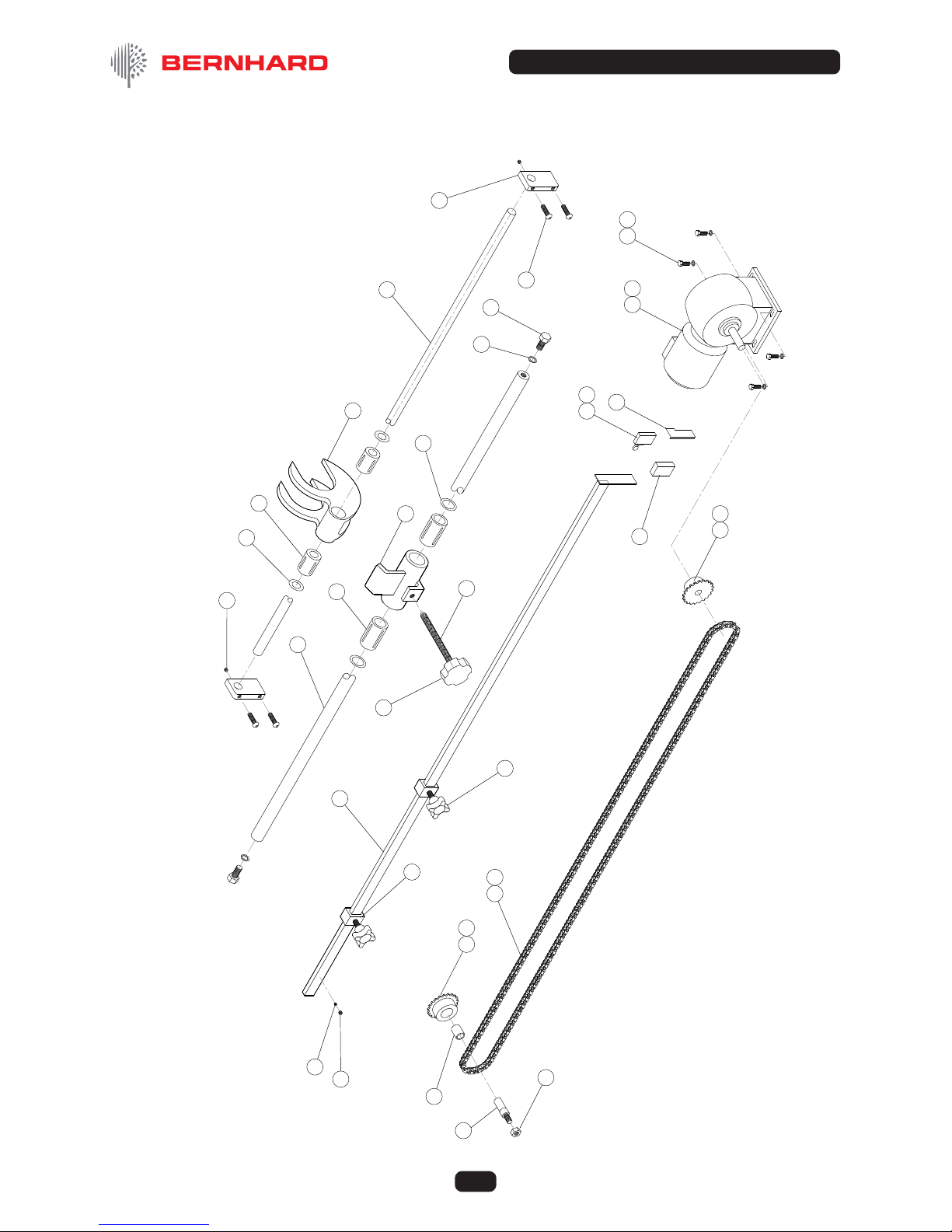
9.4 TRAVERSE ASSEMBLY
______________________________________________
1 Forkdriver (only) ...................................................................... 1 A9512
Forkdriver c/w bushings and seals ..........................................1 A9505
2 Shaft for Forkdriver .................................................................1 A9050
3 Brackets for Forkdriver Shaft .................................................. 2 A4049
4 Ball Bushing for Forkdriver ...................................................... 2 A7706
5 Dust Seals for Forkdriver ........................................................2 A7707
6 Button Head Screw M8 x 30 ................................................... 4 A5164
7 Socket Screw M6 x 6 ...............................................................2 A5156
8 Shaft for Pick up ...................................................................... 1 A9183
9 Traverse Pick Up ..................................................................... 1 A9 518
10 Ball Bushing for Trav. Pick Up ................................................. 2 A7702
11 Dust Seal for Trav. Pick Up ..................................................... 2 A7703
12 Hex. Head Screw M12 x 25 ..................................................... 2 A5712
13 Washer M12 ............................................................................2 A5315
14 Engagement Screw ................................................................. 1 A 6112
15 Lobed Knob M12 ..................................................................... 1 A6102
16 Reversing Bar .......................................................................... 1 A4111
17 Reversing Bar Stop .................................................................2 A 4113
18 Cross Knob M8 x 15 ................................................................ 2 A6131
19 Microswitch..............................................................................1 A8111
20 Housing for Microswitch ......................................................... 1 A8113
21 Guard for Microswitch ............................................................. 1 A6382
22 Screw 2BA x 1 ¾” ....................................................................2 A5404
23 Traverse Motor 60Hz ............................................................... 1 A6024
Traverse Motor 50Hz ............................................................... 1 A6022
24 Idler Sprocket ..........................................................................1 A7609
25 Oilite Bush for Sprocket .......................................................... 1 A7704
26 Spindle for Idler Sprocket ........................................................ 1 A9057
27 Drive Sprocket ......................................................................... 1 A7603
28 Traverse Chain ........................................................................ 1 A74 06
29 Link for Traverse Chain ........................................................... 1 A7502
30 Circlip ½” ................................................................................. 1 A5602
31 Hex. Nut M10 ........................................................................... 1 A5503
32 Socket Screw ..........................................................................1
33 Hex Head Screw M6 x 18 ........................................................ 4 A5719
34 Washer M6 .............................................................................. 4 A5320
35 Capacitor 3uf for Traverse Motor ........................................... 1 A814 8
36 Friction Spring for Reversing Bar ............................................1 A6 746
37 Socket Screw ¼”Whit x ¼” ...................................................... 1 A510 1
9. Parts List (Continued)
Ref # Name of Part Qty. Part #
© Bernhard and Company Limited
37
EXPRESS DUAL 4000DX
1
2
3
4
5
6
7
8
9
10
11
12
14
15
16
17
18
19
20
21
22
23
24
13
25
26
27
28 29
30
31
32
33 34
36
37
35
TRAVERSE ASSEMBLY
9. Parts List (Continued)

© Bernhard and Company Limited
38
EXPRESS DUAL 4000DX
9.5 REEL DRIVE
___________________________________________________________
1 Reel Drive Motor ...................................................................... 1 A6011
2 Layshaft (Long) .......................................................................1 A9059
3 Layshaft (Short) ....................................................................... 1 A9060
4 Layshaft Bearing ..................................................................... 2 A7722
5 Socket for Flexible Drive ......................................................... 2 A9121
6 Flexible Drive Shaft .................................................................1 A74 04
7 Flexible Drive Bracket Base .................................................... 1 A4046
8 Retaining Nut ........................................................................... 1 A4110
9 ‘L’ Post Drive Hd Support Bar .................................................1 A4001
10 Flexible Drive Bracket ............................................................. 1 A4045
11 Cylinder Drive Motor Bracket ..................................................1 A 4031
12 Cross Knob M8 x 15 ................................................................ 2 A6131
13 Ball Spring Plunger ................................................................. 2 A5460
14 Cap Hd Screw 5/8”Whit x 5 1/2” .............................................1 A5109
15 Socket Screw M6 x 12 .............................................................1 A5146
16 Diamond Dresser ....................................................................1 A6737
17 Locknut M10 ............................................................................ 1 A5503
18 Flexible Coupling .....................................................................1 A6744
19 Grub Screw 3/8” Whit x 3/8”....................................................2 A5106
20 Short Square Drive Shaft ........................................................ 1 A 413 4
Ref # Name of Part Qty. Part #
9. Parts List (Continued)

© Bernhard and Company Limited
39
EXPRESS DUAL 4000DX
18
19
20
5
4
2
8
6
7
9
1
5
4
3
10
11
12
14
15
16
13 17
REEL DRIVE
9. Parts List (Continued)

© Bernhard and Company Limited
40
EXPRESS DUAL 4000DX
Ref # Name of Part Qty. Part #
9.6 CLAMP ASSEMBLY
____________________________________________________
1 Radius Pressure Arm Bracket ................................................. 1 A 410 1
2 Radius Pressure Arm .............................................................. 1 A 410 0
3 Pressure Bar Rubber...............................................................2 A6761
4 Linear Actuator ........................................................................ 1 A6 013
5 Plug 4 Pin ................................................................................ 1 A8121
6 Hex Head Bolt M16 x 170 ........................................................1 A5 749
7 Nyloc Nut M16 ......................................................................... 1 A5524
8 C’s’k Socket Screw M10 x 30 .................................................. 4 A 5117
9 Nut M10 ...................................................................................4 A5503
10 Hex Head Bolt M10 x 45 ..........................................................2 A5706
11 Nyloc Nut M10 ......................................................................... 2 A5505
12 Washer M10 ............................................................................6 A5310
13 Pressure Plate (not shown) ....................................................1 A6342
9. Parts List (Continued)

© Bernhard and Company Limited
41
EXPRESS DUAL 4000DX
1
2
3
4
5
6 7
8
9
10
11
12
CLAMP ASSEMBLY
9. Parts List (Continued)

© Bernhard and Company Limited
42
EXPRESS DUAL 4000DX
9.7 MULTI-FIX BRACKET ASSEMBLY
_________________________________
1 Adjustable Mtg Brkt Base L.H. ................................................ 1 A4 012
2 Adjustable Mtg Brkt ‘V’ Base ..................................................2 A 4 011
3 Adjustable Mtg Brkt Base R.H. ...............................................1 A4014
4 ‘L’ Upright Mounting Brkt R.H. ................................................. 1 A4010
5 ‘L’ Upright Mounting Brkt L.H. ................................................. 1 A4009
6 Adjustable Mtg Brkt Horizontal ...............................................2 A4016
7 Mounting Brkt ‘C’ Clamp L.H. .................................................1 A4006
8 Mounting Brkt ‘C’ Clamp R.H. ................................................. 1 A4007
9 ‘C’ Clamp Screw ......................................................................2 A4008
10 ‘V’ Bracket Clamp Finger ........................................................ 2 A4003
11 Kip Lever M10 x 20 .................................................................. 4 A6118
12 ‘V’ Bracket Stud M16 ............................................................... 2 A5401
13 Kip Lever M12 x 30 .................................................................. 4 A6121
14 Slide Nut M10 .......................................................................... 2 A 4180
15 Nut M16 ..................................................................................2 A5508
16 Wing Nut M16 .......................................................................... 2 A5509
17 Cap Head Skt Screw M10 x 25 ..............................................4 A 5116
18 Washer M12 ............................................................................4 A5315
19 Washer M10 ............................................................................4 A5310
20 Base Scale ..............................................................................2 A6601
21 Button Head Skt Screw M4 x 8 ............................................... 4 A5125
22 Multix Channel (not shown) ................................................... 2 A4087
Ref # Name of Part Qty. Part #
9. Parts List (Continued)

© Bernhard and Company Limited
43
EXPRESS DUAL 4000DX
1
2
3
4
5
6
7
8
9
10
11
11
12
13
14
15
16
17
18
19
20
21
MULTI-FIX BRACKET
ASSE M B LY
9. Parts List (Continued)

© Bernhard and Company Limited
44
EXPRESS DUAL 4000DX
9.8 GUARD
_________________________________________________________________
1 Guard Roof Fabrication ........................................................... 1 A03553
2 Guard RH End Fabrication (Electrical Enclosure) .................. 1 A03554
3 Guard LH End Fabrication (Storage) ...................................... 1 A03555
4 Guard Front Fabrication .......................................................... 1 A03556
5 Polycarbonate Retainer Assembly ..........................................1 A03557
6 Guard Linkage Assembly ........................................................ 1 A03546
7 Guard Rear Flap Fabrication................................................... 8 A03565
8 Guard LH Rear Inll Fabrication ............................................. 2 A03559
9 Guard LH Rear Inll Fabrication ............................................. 1 A03558
10 Guard Light Bracket Fabrication .............................................1 A03564
11 Guard LH Door End Fabrication ............................................. 1 A03567
12 Guard RH Door End Fabrication .............................................4 A03566
13 Guard Polycarbonate .............................................................. 2 A03560
14 Electrical Panel Chassis Plate Fabrication ............................. 1 A03618
Ref # Name of Part Qty. Part #
9. Parts List (Continued)

© Bernhard and Company Limited
45
EXPRESS DUAL 4000DX
12
1
7
8
9
10
11
3
6
5
4
13
14
2
GUARD
9. Parts List (Continued)

© Bernhard and Company Limited
46
EXPRESS DUAL 4000DX
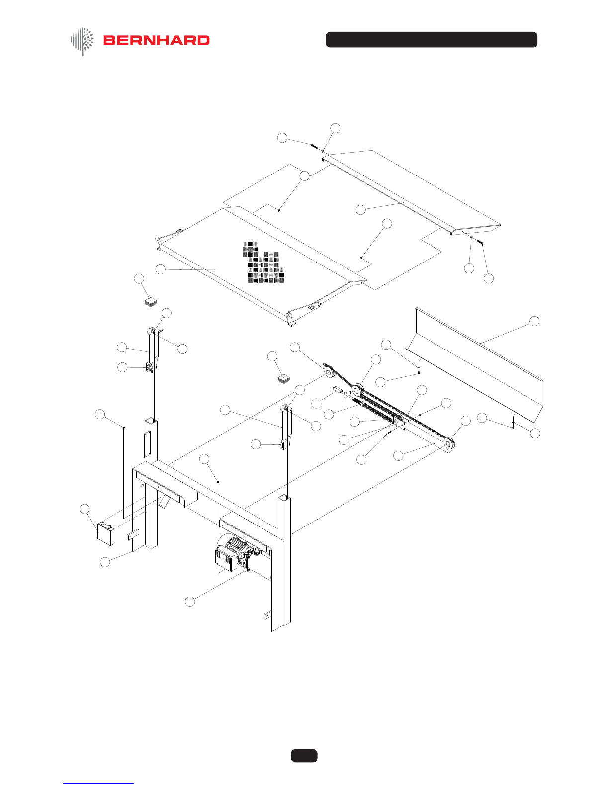
9.11 LIFT TABLE
__________________________________________________________
1 Frame ...................................................................................... 1 A413 8
2 Power Pack 220v .................................................................... 1 A8954
Power Pack 24v ....................................................................... 1 A8023
Power Pack 12v ....................................................................... 1 A8770
3 L.H. Slider Plate ......................................................................1 A4127
4 R.H.Slider Plate ....................................................................... 1 A4128
5 Bearing .................................................................................... 2 A7 744
6 Bearing .................................................................................... 2 A7 744
7 Slider Plate Pin ........................................................................ 2 A4127
8 Plastic End Cap 60 x 60 ......................................................... 2 A619 4
9 Taillift Platform .........................................................................1 A4139
10 Single Pulley ............................................................................2 A7209
11 Double Pulley ..........................................................................2 A7204
12 Hydraulic Cylinder complete ...................................................1 A6923
13 Chain Screw Tensioner ........................................................... 2 A4119
14 Chain Bottle Tensioner ............................................................ 2 A4022
15 L.H. Pulley Mounting Plate ...................................................... 2 A4098
16 Hex Head Bolt M6 x 45 ........................................................... 1 A5722
17 Nyloc Nut M6 ........................................................................... 1 A 5517
18 R.H.Pulley Mounting Plate ...................................................... 1 A4099
19 Cover Plate .............................................................................. 1 A6319
20 Washer M6 .............................................................................. 2 A5320
21 Hex Head Screw M6 x 12 ........................................................2 A5718
22 Nut M6 ..................................................................................... 2 A5 516
23 Lift Platform Extension ............................................................ 1 A413 7
24 Washer M8 .............................................................................. 2 A5321
25 Hex Head Set Screw M8 x 45 ................................................. 2 A5725
26 Nyloc Nut M8 ........................................................................... 2 A5220
27 Lift Table Lowering Solenoid 220v ..........................................1 A8943
Lift Table Lowering Solenoid 24v ............................................ 1 A8392
Lift Table Lowering Solenoid 12v ............................................ 1 A8391
28 Control Pendant 24v (not shown) ............................................1 A8018
Mains Control Pendant (not shown) ........................................ 1 A8890
29 Label for Tail Lift Pendant (not shown) .................................... 1 A6552
30 Mains Tail Lift Controller (not shown) ...................................... 1 A8904
Ref # Name of Part Qty. Part #
9. Parts List (Continued)
© Bernhard and Company Limited
47
EXPRESS DUAL 4000DX
1
5
4
7
6
8
9
10
8
11
11
10
12
2
5
3
6
7
13
14
15
16
17
20
18
19
21
21
20
23
24
25
25
24
22
22
26
26
30
LIFT TABLE
9. Parts List (Continued)

© Bernhard and Company Limited
48
EXPRESS DUAL 4000DX
9.9 CONTROL BOX (OMRON NS5)
_____________________________________
1 Control Box and Lid ................................................................. 1 A6973
2 Control Box Arm ...................................................................... 1 A4028
3 On –Off Switch (Control System) ............................................ 1 A8155
4 Comm’s Lead, HMI - PLC ........................................................ 1 A3586
5 1k Potentiometer ..................................................................... 1 A8014
6 Emergency Stop Button ..........................................................1 A8073
7 B4T02 Contact Block (for the above) ...................................... 1 A8358
8 Omron Graphical Operator Panel (HMI) touch screen .......... 1 A8500
9 Label ....................................................................................... 1 A6549
Ref # Name of Part Qty. Part #
9. Parts List (Continued)
2
3
5
VIEW WITH HINGED LID OPEN
9
6
3
5
7
8
4
1
10
CONTROL BOX
OMRON NS5

© Bernhard and Company Limited
49
EXPRESS DUAL 4000DX
ELECTRICAL PANEL
9. Parts List (Continued)
9.10 ELECTRICAL JUNCTION BOX
Main
(grind)
PLC (Cpu-
includes
encoder
input &
comms)
PLC
Input
module
Transformer
24V (AC)
output
Safety
Vac’ Trav’
left
Contactors
Overload
Relay
Feed motor
up
Rectifier
(
DC out
)
Relay
Feed motor
down
Relay
Clamp
up (on)
Relay
Clamp
Down (off)
Fuses
PLC
Output
module
Trav’
ri
g
ht
PLC
(psu
Regulated
PSU
24V dc
output
Inverter
Reel speed
control
Traverse
capacitor
ISOLATOR SWITCH
ENCODER
CONNECTIONS
SIDE ARM LIMIT
SWITCH WIRES
TO OPERATOR
PANEL
TO MAIN
ELECTRICAL PANEL
SUPPLY FUSES
F1,F2, 16A (x2)
A8084
MAINS INLET
SUPPLY FUSE
HOLDER (x2)
A8081
A08373

© Bernhard and Company Limited
50
EXPRESS DUAL 4000DX
ELECTRICAL PANEL
____________________________________________________
1 PLC Power Supply Unit ........................................................... 1 A3537
2 PLC CPU (includes High Speed Encoder Count Module) ...... 1 A3536
3 PLC Input Module .................................................................... 1 A3538
4 PLC Output Module ................................................................. 2 A3539
5 Contactor 24v DC ....................................................................5 A6973
6 Thermal Overload Contactor ..................................................1 A8368
7 Relay 24v DC...........................................................................4 A8380
8 Relay Base .............................................................................. 1 A8381
9 Rectier ...................................................................................1 A8350
10 Transformer 24v AC out ( VA) ............................................1 A3301
11 Fuseholder............................................................................... 8
12 Fuse F3 – 6.3A Inverter ......................................................1 A8087
Fuse F4 – 5A Vacuum ..................................................... 1 A8086
Fuse F5 – 2A Traverse Motor .......................................... 1 A8085
Fuse F6 – 1.25A Regulated Power Supply ........................... 1 A8082
Fuse F7 – 5A Transformer Primary (Mains) ....................1 A8086
Fuse F8 – 5A Unregulated 24v DC .................................. 1 A8086
Fuse F9 – 2A Light ........................................................... 1 A8085
Fuse F10 – 6.3A Lift table ..................................................... 1 A8087
13 Regulated 24v DC Power Supply ............................................ 1 A3456
14 Inverter – Reel Speed Control ................................................1 A3542
15 Traverse Capacitor – 3uF ........................................................1 A8148
Ref # Name of Part Qty. Part #
9. Parts List (Continued)
1
2
3
6
5
15
8
9
10
13
14
11
4
7

EXPRESS LIFT TABLE MANUAL
EXPRESS LIFT TABLE
Please read this manual carefully.
This manual should be kept in a safe place so that it can be used for future reference.
for Express Dual Spin Grinders
User’s Guide &
Instruction Manual

52
EXPRESS DUAL LIFT TABLE
© Bernhard and Company Limited
FIG. 1. – OVERALL VIEW WITH COVER REMOVED
FIG. 2. – TABLE HEIGHT ADJUSTING DETAIL
ADJUSTER A – Raises/Lowers Left Hand Side
ADJUSTER B – Raises/Lowers Right Hand Side

53
EXPRESS DUAL LIFT TABLE
© Bernhard and Company Limited
EXPRESS DUAL
Contents
BERNHARD & CO. LIMI TED
Bilton Road • Rugby • England • CV22 7DT
Tel +44 1788 811600 • Fax +44 1788 812640
Email: i n fo@bernhard.co.uk
USA Toll Free 1-888 GRIND IT (1-888 474 6348
)
Express Dual Lift Table
The Express Lift Table is a carefully designed hydraulic lift table purpose built for
attachment to the Express Dual lawn mower reel-grinding machine. Its robust
construction and attention to detail should ensure a long and trouble free life.
However, as with all mechanical handling devices caution is required, safe
operation can be assured only by constant attention to the operating and
maintenance instructions contained in this manual.
It is therefore essential that the responsible person ensure that this machine is
operated and/or serviced only by suitably qualied personnel who have read and
properly understood this manual.
If you have any service or operational problems contact your distributor,
or phone our
Technical Helpline (USA only) – 1-888 474 6348
or
Bernhard and Company Ltd, England – (+44) 1788 811600
or email
techsupport@bernhard.co.uk
use the technical support feedback form on our web site
www.expressdual.com or www.bernhard.co.uk
Safety 3
General Description 4
Operating Procedure 5
Maintenance and Adjustments 6
Fault Finding 7
Parts List and Diagrams 8

54
EXPRESS DUAL LIFT TABLE
© Bernhard and Company Limited
1.1 Never load the lift table with more than the rated weight (The rating is shown on a label on
the rear of the cover plate – visible when the lift platform plate is in it’s lowered position).
1.2 Always ensure that any load is placed as near as possible in the centre of the table.
1.3 Never ride on the left lift.
1.4 Never attempt to lift an unstable load.
1.5 Never use the table to try to assist another lifting device to lift a large load.
1.6 Always carry out routine checks and maintenance as instructed in this manual and at the
correct intervals.
1.7 When lowering the platform from the vertical position do not let it fall under its own weight.
1.8 When not in use always latch the platform into the vertical position or leave it horizontal at
ground level.
1.9. When lowering a load ensure that the oor space below the table is clear of all objects.
1. Safety

55
EXPRESS DUAL LIFT TABLE
© Bernhard and Company Limited
2. General Description
The Express Lift table consists of a fabricated steel mainframe assembly with two vertical
rolled steel channels in which the platform carriages are located. The hinged platform is
constructed from aluminium-chequered plate to give high strength combined with ease of
handling.
Power is supplied by an electro-hydraulic pack with the single hydraulic ram exerting the
lift force through a pair of adjustable lifting chains.
Early units used a power pack with a 12v DC electric motor, powered through a
transformer wired directly into the Express Dual grinding machine.
Then from March 1998 units utilised a 24v DC power pack and transformer.
From March 2003 the lift power unit is now 220v AC.
All are controlled by a hand held push button panel, which controls both the raising and
lowering functions.

56
EXPRESS DUAL LIFT TABLE
© Bernhard and Company Limited
3.1 When not in use the lift platform is normally stored in its lowest position, with the table
clipped in the vertical position.
3.2 To bring into use press the ‘UP’ button on the control panel until the platform has risen to a
convenient height, then unclip the platform and lower it into the horizontal position.
NOTE: It is advisable not to allow the platform to fall under its own weight.
3.3 When the platform is horizontal press the ‘DOWN’ button to lower the platform to the oor
and place the mower unit onto the platform. Ensure that the unit is as central as possible
and stable before pressing the ‘UP’ button to bring the platform to the height of the
Express Dual table.
NOTE: When the platform reaches its top position the hydraulic power pack will bypass the lifting
pressure. Release the “UP” button. DO NOT PRESS IT AGAIN WHILST THE TABLE IS IN
IT’S UPPERMOST POSITION.
3.4 When the unit has been moved onto the Dual table return the platform to its normal
storage position to allow better access to the Dual table and avoid the risk of personal
injury on the projecting corners of the platform.
3.5 Unload the Dual table in the reverse order.
3. Operating Procedure

57
EXPRESS DUAL LIFT TABLE
© Bernhard and Company Limited
4. Maintenance and Adjustment
NOTE: Maintenance and adjustment should be carried out by suitably qualied/trained personnel
in accordance with the information in this Manual.
As the conditions and frequency of use will vary greatly the following recommendations
should be modied if required to suit the prevailing circumstances.
The Express Dual Lift Table is designed and constructed to require the minimum of
maintenance. The 3 main requirements are:
1. The correct voltage at the motor terminals when the controls are activated.
2. The correct amount of clean hydraulic uid of an appropriate grade in the hydraulic system.
3. No build up of dirt or debris around any of the moving parts.
NOTE: When cleaning the Express Dual machine ensure that none of the dust or debris from the
grinding process is allowed to enter the Lift table mechanism.
The following checks should be carried out at approximately the intervals stated:
MONTHLY
Visually check the complete unit, conrm that all xings are secure, that all electrical
connections are tight, and that the hydraulic uid is at the correct level with no visible
hydraulic leaks.
3 MONTHLY
In addition to the monthly checks, ensure that the lift platform is level with the Express
Dual table at the top of its travel. Adjust if required using the two adjusters (part#14 on
exploded parts diagram)
12 MONTHLY
In addition to the above checks, ensure that all parts are clean and free from any damage
or obvious wear. Raise the table to the top of its travel and apply a small amount of grease
over the whole length of both chains.
On DC powered units visually check the motor brushes for wear.
NOTE: When any moving parts have been replaced or cleaned with a degreasing agent, ensure
that they are re-assembled with an adequate quantity of medium grease.

58
EXPRESS DUAL LIFT TABLE
© Bernhard and Company Limited
5. Fault Finding
In the event of faulty operation, the following procedure is recommended.
• Check that all moving components are clean and are able to move freely and that they are
free from any obvious damage or wear.
• If the lift fails to raise:
1. Check the fuses.
2. Use a test meter to check that the correct voltage is present at the motor terminals when
the control buttons are operated. If the voltage is low/missing, check back through the
circuit to locate the loss of voltage, usually a loose or dirty connection is the cause (on DC
units- nally, check the condition of the motor brushes and their freedom to move).
• If the lift fails to lower:
1. Check the fuses.
2. Check the voltage at the dump solenoid – if all is OK then the solenoid has probably failed.
If not check back check back through the circuit to locate the loss of voltage.
• If the table drifts/drops slightly over time:
1. Visually check for leaks throughout the system (Power pack, ram, hose) (possible seal
failure).
2. Check dump valve solenoid – could be debris under the seating or a valve failure.
TECHNICAL SPECIFICATIONS
Hydraulic Oil I.S.O.32 (eg catrol hysol XH)
Capacity 0.9litre (2 pints USA)
Max Hydraulic Pressure 140 Bar (Full Load)

59
EXPRESS DUAL LIFT TABLE
© Bernhard and Company Limited
LIFT TABLE
________________________________________________________________
1 Frame ...................................................................................... 1 A413 8
2 Power Pack 220v .................................................................... 1 A8954
Power Pack 24v ....................................................................... 1 A8023
Power Pack 12v ....................................................................... 1 A8770
3 L.H. Slider Plate ......................................................................1 A4127
4 R.H.Slider Plate ....................................................................... 1 A4128
5 Bearing .................................................................................... 2 A7 744
6 Bearing .................................................................................... 2 A7 744
7 Slider Plate Pin ........................................................................ 2 A4127
8 Plastic End Cap 60 x 60 ......................................................... 2 A619 4
9 Taillift Platform .........................................................................1 A4139
10 Single Pulley ............................................................................2 A7209
11 Double Pulley ..........................................................................2 A7204
12 Hydraulic Cylinder complete ...................................................1 A6923
13 Chain Screw Tensioner ........................................................... 2 A4119
14 Chain Bottle Tensioner ............................................................ 2 A4022
15 L.H. Pulley Mounting Plate ...................................................... 2 A4098
16 Hex Head Bolt M6 x 45 ........................................................... 1 A5722
17 Nyloc Nut M6 ........................................................................... 1 A 5517
18 R.H.Pulley Mounting Plate ...................................................... 1 A4099
19 Cover Plate .............................................................................. 1 A6319
20 Washer M6 .............................................................................. 2 A5320
21 Hex Head Screw M6 x 12 ........................................................2 A5718
22 Nut M6 ..................................................................................... 2 A5 516
23 Lift Platform Extension ............................................................ 1 A413 7
24 Washer M8 .............................................................................. 2 A5321
25 Hex Head Set Screw M8 x 45 ................................................. 2 A5725
26 Nyloc Nut M8 ........................................................................... 2 A5220
27 Lift Table Lowering Solenoid 220v ..........................................1 A8943
Lift Table Lowering Solenoid 24v ............................................ 1 A8392
Lift Table Lowering Solenoid 12v ............................................ 1 A8391
28 Control Pendant 24v (not shown) ............................................1 A8018
Mains Control Pendant (not shown) ........................................ 1 A8890
29 Label for Tail Lift Pendant (not shown) .................................... 1 A6552
30 Mains Tail Lift Controller (not shown) ...................................... 1 A8904
Ref # Name of Part Qty. Part #
6. Parts List

60
EXPRESS DUAL LIFT TABLE
© Bernhard and Company Limited
1
5
4
7
6
8
9
10
8
11
11
10
12
2
5
3
6
7
13
14
15
16
17
20
18
19
21
21
20
23
24
25
25
24
22
22
26
26
30
LIFT TABLE
6. Parts List (Continued)

© Bernhard and Company Limited
61
EXPRESS DUAL 4000DX
EXPRESS DUAL 4000DX
USER QUICK START GUIDE
Connect grinder to 220/240v a.c. mains supply.
Switch on the on-off/reset switch on the operator control (HMI) box.
Backlit control panel screen (HMI) should light up and, following a warm up/initiation
routine, (around 90 seconds as the programme is loaded into the operator panel) display
the rst screen. If not, switch on the on-off/reset switch on the operator control (HMI) box.
Follow the screen prompts/instructions
• Press the icons/buttons on the screen.
• Operation buttons run along the “button bar” at the base of the display screen and are
green until turned on when they change to red.
• Certain buttons will turn grey to show that they are inactive when it would not be
appropriate for that function to be accessed.
• Selection buttons (for mower size, grind type) are larger icons in the central area of the
screen.
Screen 1 — “Welcome” screen
• Select Automatic operation
Or
• Select Manual operation
Selection proceeds to next screen
NOTE: Once a mode has been selected, the unit will remain in that mode, Manual or Automatic for
all subsequent operations.
To change mode:
• Press the required operation mode button (only appears in certain screens) or
• Press the on-off/reset switch on the operator control (HMI) box, to reset control system
(HMI screen goes blank).
• Wait 20 seconds before turning switch back on again.
• Select alternative mode of operation when system re-loads.

© Bernhard and Company Limited
62
EXPRESS DUAL 4000DX
AUTO MODE:
Screen 2 — “Mount mower”
• Place mower on m/c table.
• Undo traverse engagement screw
(VERY IMPORTANT).
• Engage clamp
• Undo clamp
• Press Green arrow to continue
Screen 3 — “Dene size of mower”
• Smaller units (or Greens)
• Medium sized units
(or Tees / Light Fairway)
• Large units (or Fairway)
Selection proceeds to next screen
Screen 4 — “Choose rate of grind”
• Press icon / button to select grind
required: (Picture size represents
aggression of grind cycle)
• Touch-up grind, quickest, to restore
sharpness on a well maintained but
“dulled” unit.
• Maintain grind, more work required to
restore the edge.
• Rectication grind, restoration of a
damaged blade.
Selection proceeds to next screen
User Quick Start Guide (Continued)

© Bernhard and Company Limited
63
EXPRESS DUAL 4000DX
Screen 5 — “Conrmation of selected cycle”
• Screen displays mower size and degree of
grind selected.
• CLOSE SAFETY GUARD and conrm
selection to proceed to next stage.
• Conrm selection is ok.
• Re-select (returns to screen 4-”mower size”)
NOTE: REEL (SPIN), GRINDSTONE AND TRAVERSE MOTORS WILL NOW START
NOTE: If guard is not closed a warning screen will appear.
Closing guard will return to display screen 5 (conrm selection).
Screen 6 — Set “Ready to grind”
• Set grind-stone to reel, stone is moved,
by manual adjustment of the feed
handwheels, so that it touches and gently
sparks at both ends of the reel. Using the
(still loosened) feed engagement screw,
manually traverse the ‘stone along the
length of the reel ensuring even contact all
the way across.
• Set traverse / reversing stops so that the leading edge of the grindstone passes the
end of the reel but does not contact any part of the mower frame. The stone should
NOT completely pass the end of the reel.
• Engage the traverse screw. Screw in the knob so that the stone is automatically
traversing the length of the reel.
• Press forward arrow (“next”) to proceed to next screen.
• Note: the back arrow button (to stop all motors and return to the ‘conrm selection
screen will not appear until all motors are up to speed.
User Quick Start Guide (Continued)
Number refers to
program parameter array
selected (ref. for operator
conguration if desired)

© Bernhard and Company Limited
64
EXPRESS DUAL 4000DX
Screen 7 — “Running programme”
• Grinding cycle commences. Images of reel
and grind stone appear on screen.
• Both handwheels move together to apply a
parallel cut to the reel (Amount according
to cycle selected).
• After several traverse passes of stone
across the reel a further feed of cut is
applied.
• Several feeds / traverses may be applied
according to the cycle selected.
• After the nal feed extra traverse passes will be made to ensure a good nish then:
• Both handwheels reverse, grindstone moves away from reel.
• All motors stop.
• Next screen appears.
• To interrupt a grind cycle (eg to check if reel condition before completion of a grind
cycle) Press button shown to “PAUSE” the cycle.
• Both handwheels reverse, grindstone moves away from reel.
• All motors stop.
Screen 8 — “Programme Paused”
• Check condition of reel
• Press “GO” button to restart machine,
“resume” and complete cycle. Motors will
re-start, handwheels will feed grind stone
to position where cycle was interrupted
and cycle will continue as before until
handwheels back off and motors stop.
NOTE: If guard is not closed warning screen
will appear. Closing guard will return to
“paused” screen. Restart machine.
• Press “nished” button to “End” cycle. Screen 9 appears.
User Quick Start Guide (Continued)

© Bernhard and Company Limited
65
EXPRESS DUAL 4000DX
User Quick Start Guide (Continued)
Screen 9 — “Programme completed”
• Check condition of reel / result of grind.
DO NOT ADJUST FEED HANDWHEELS.
• Select “Finished” if reel is nished OK.
Progress to Next Screen.
• Select “Re-Do” if you think blades still
require some work, and re run complete
cycle.
• Select “Touch up” if blades are “not quite
there” and require a light nishing grind.
• If “re-do” or “touch up” buttons are selected, machine motors will re-start, handwheels
will feed grind stone to position where previous cycle nished and next cycle will
commence and proceed as before until handwheels back off and motors stop. Screens
7 and 9 will appear accordingly.
Screen 10 — “Grinding completed”
• Press button to undo clamp and remove
mower from machine.
• Press “next” to return to “mount mower”
screen 2, ready for next mower.
End of “Automatic” Section.

© Bernhard and Company Limited
66
EXPRESS DUAL 4000DX
3. User Quick Start Guide (Continued)
MANUAL MODE:
• Moving bars show balance.
• Left and Right hand position
values appear on operator panel.
• Motors can be started and stopped
by pressing the icons as directed:
Icon is green (push to start) turns
red when on (push to stop).
• Grind stone motor.
• Reel control (spin) motor.
• Traverse motor.
• RESET counters.
• Automatic (change mode).
In Manual Mode, Express Dual can be operated as a normal, non-automatic machine.
Individual motors can be started and stopped using the relevant function keys (The keys “toggle”
on then off).
All motors can be stopped using the Red, mushroom headed, “E” stop button.
This will result in an error screen appearing on the operator panel. This is for information only,
follow the screen prompts to continue operation (Also see Notes – “Other screens”).
For general operation notes see main user manual.
NOTES:
• Engage clamp – lock down mower
• Disengage / undo clamp
End of “Manual” Section.

© Bernhard and Company Limited
67
EXPRESS DUAL 4000DX
3. User Quick Start Guide (Continued)
Other Screens:
(I) “Guard Open”
• If the safety enclosure (guard) is opened
whilst any motor or program is running.
All motors will stop and the “Guard Open”
warning screen appears.
• Check machine for any potential
problems before releasing “E” stop button
(by twisting counter-clockwise) and resetting machine by pressing this button.
(II) “Emergency Stop Activated”
• Warning message indicates emergency
stop button has been depressed.
• Check machine for any potential
problems before releasing “E” stop
button (by twisting counter-clockwise)
and re-setting machine by pressing this
button.
(III) “Main Motor Thermal Overload Activated”
• Warning message when machine is
tripped out by the overload relay on the
main grind motor.
• Could be low voltage (increased
Amperage) or a motor/drive problem.
• Check machine before pressing blue
rest button on main electrical control
box and re-setting machine by pressing
this button.

© Bernhard and Company Limited
68
EXPRESS DUAL 4000DX
3. User Quick Start Guide (Continued)
(III) “Main Shaft has bottomed out”
• Mainshaft has reached lowest limit
of travel, (bottomed out against
chassis limit switch). Machine stops
since further travel would cause m/c
control to lose position reference.
Could crash program or damage
feed drive train.
• Display advises manual raising
of shaft by two revolutions of the
handwheel on each side.
• Press the mainshaft button to re-set
the machine.

© Bernhard and Company Limited
69
EXPRESS DUAL 4000DX
3. User Quick Start Guide (Continued)
(III) User Conguration –
use of the “SYS” menu
• Push the BCo logo on the start up/ welcome screen.
• The password entry popup appears.
• Touch the data entry area to call up the keypad
• Key in the number 1111 and hit the return key
• Screen shows 4 stars to correspond with 4 entered
digits
• Push the OK button
• The “System menu” screen appears
• Various button options appear
Back to the “power up/welcome” screen
Terminal parameters – access to adjust operator panel settings
Change password (currently disabled)
Adjust grind parameters- access to grind cycle parameter table
Default parameters- access to restore default settings
Engineering menu – access to engineering menu (not user accessible)

© Bernhard and Company Limited
70
EXPRESS DUAL 4000DX
3. User Quick Start Guide (Continued)
Changing Grind Parameters
• Push the BCo logo on the start up/ welcome screen.
• The password entry popup appears.
• Touch the data entry area to call up the keypad
• Key in the number 1111 and hit the return key
• Screen shows 4 stars to correspond with 4 entered
digits
• Push the OK button
• The “System menu” screen appears
• Various button options appear
Back to the “power up/welcome” screen
Terminal parameters – access to adjust operator panel settings
Change password (currently disabled)
Adjust grind parameters- access to grind cycle parameter table
Default parameters- access to restore default settings
Engineering menu – access to engineering menu (not user accessible)

© Bernhard and Company Limited
71
EXPRESS DUAL 4000DX
NOTES
.....................................................................................................................................................................................................................................................................
.....................................................................................................................................................................................................................................................................
.....................................................................................................................................................................................................................................................................
.....................................................................................................................................................................................................................................................................
.....................................................................................................................................................................................................................................................................
.....................................................................................................................................................................................................................................................................
.....................................................................................................................................................................................................................................................................
.....................................................................................................................................................................................................................................................................
.....................................................................................................................................................................................................................................................................
.....................................................................................................................................................................................................................................................................
.....................................................................................................................................................................................................................................................................
.....................................................................................................................................................................................................................................................................
.....................................................................................................................................................................................................................................................................
.....................................................................................................................................................................................................................................................................
.....................................................................................................................................................................................................................................................................
.....................................................................................................................................................................................................................................................................
.....................................................................................................................................................................................................................................................................
.....................................................................................................................................................................................................................................................................
.....................................................................................................................................................................................................................................................................
.....................................................................................................................................................................................................................................................................
.....................................................................................................................................................................................................................................................................
.....................................................................................................................................................................................................................................................................
.....................................................................................................................................................................................................................................................................
.....................................................................................................................................................................................................................................................................
.....................................................................................................................................................................................................................................................................
.....................................................................................................................................................................................................................................................................

BERNHARD & CO. LIMI TED
Bilton Road • Rugby • England • CV22 7DT
Tel +44 1788 811600 • Fax +44 1788 812640
Email: info@bernhard.co.uk
USA Toll Free 1-888 GRIND IT (1-888 474 6348
)
If you have any service or operational issues please contact your distributor
or phone our technical support hotline
Technical Helpline (USA only) 1-888 474 6348
Rest of World: UK Head Ofce, England (+44) 1788 811600
Email: techsupport@bernhard.co.uk
Technical FAQs can be found on our web site: www.bernhard.co.uk
When ordering spare parts please quote the machine type and serial number.
THE MANUFACTURERS ACCEPT NO RESPONSIBILITY FOR ANY SITUATION ARISING FROM
THE FITTING AND/OR USE OF NON-ORIGINAL SPARE PARTS.
 Loading...