

Page 1
Page 2

2 3
CONTENTSSAFETY INSTRUCTIONS
IMPORTANT SAFETY
INSTRUCTIONS
When using an electrical appliance, basic safety precautions
should always be followed, including the following:
Read all instructions before using this sewing computer.
When the sewing computer is not in use, it should be
disconnected from the electricity supply by removing the
plug from the outlet.
DANGER!
To reduce the risk of electrical shock:
1. The sewing computer should never be left unattended when
plugged in.
2. Always unplug the sewing computer from the electrical outlet
immediately after using and before cleaning.
3. Always unplug before replacing light bulb. Replace bulb with
same type rated 15 watts.
WARNING!
To reduce the risk of burns, fire, electric shock or injury to
persons:
1. Use the sewing computer only for purposes as described in
this manual. Use only attachments/accessory recommended by
the manufacturer as contained in this manual.
2. Do not allow the sewing computer to be used as a toy. Close
attention is necessary when this sewing computer is used by
or near children and infirm persons. This sewing computer is
not intended for use by persons (including children) with
reduced physical, sensory or mental capabilities, or lack of
experience and knowledge, unless they have been given
supervision or instruction concerning use of the sewing
computer by a person responsible for their safety. Children
must be kept under supervision to ensure that they do not
play with the sewing computer.
3. Never operate this sewing computer if:
█
it has a damaged cord or plug
█
it is not working properly
█
it has been dropped or damaged
█
it has fallen into water
Take the sewing computer to the nearest authorized dealer
for examination, repair, electrical or mechanical adjustment.
4. Never operate the sewing computer with any air vents
blocked. Keep ventilation openings of the sewing computer
free from lint, dust and/or fabric bits.
5. Keep fingers away from all moving parts. Special care is
required in the needle area of the sewing computer.
6. Never drop or insert any objects into any opening on the
sewing computer.
7. Do not use the sewing computer outdoors.
8. Do not operate the sewing computer where aerosol products
(spray) or oxygen is being administered.
9. Do not pull or push the fabric while stitching. This may deflect
the needle, causing it to break.
10. Do not use bent needles.
11. Always use the original stitch plate. The wrong stitch plate
can cause needle breakage.
12. To disconnect, turn power switch to «0» (off), then remove
the plug from the outlet. Do not unplug by pulling the cord,
instead grasp the plug to pull it from the outlet.
13. Turn power switch to «0» (off) when making any adjustments
in the needle area, such as changing the needle or the
presser foot, etc.
14. Always unplug the sewing computer from the electrical outlet
when carrying out cleaning or maintenance work or any other
user servicing adjustments mentioned in this manual.
15. This sewing computer is provided with double insulation
(except USA and Canada). Use only genuine replacement
parts. Please note the advice on the servicing of doubleinsulated products
DISCLAIMER
No liability will be assumed for any possible damage which arises
from misuse of this overlock machine.
This overlock machine is intended for household use only.
FOOT CONTROL
(USA & CANADA ONLY)
Use Matsushita Electric, Model YC-482E with this overlock
machine.
POLARIZED PLUGS
CAUTION (USA & CANADA ONLY)
This appliance has a polarized plug (one blade wider than the
other). To reduce the risk of electric shock, this plug is intended
to fit in a polarized outlet only one way. If the plug does not fit
fully in the outlet, reverse the plug. If it still does not fit, contact a
qualified electrician to install the proper outlet. Do not modify the
plug in any way.
SAVE THESE
INSTRUCTIONS!
This appliance complies with EEC Directive 2004/108/EC
covering the electromagnetic compatibility.
MACHINE OVERVIEW AND INSTALLATION
█
Details of the Machine 4-5
█
Machine Setup 6-8
4-8
9-13
14-21
25-27
28-31
22-24
OPERATING INSTRUCTIONS
█
Basic Operating Procedures 9
█
Adjustments and Settings 9-11
█
Needle and Thread 12
█
Needle - Thread Selection Table 13
SERGER / OVERLOCK STITCH FORMATIONS
█
Threading your Machine 14-16
█
Helpful Hints 17-20
█
Trial Sewing - Serger / Overlock 21
MAINTENANCE
█
Maintenance 25
█
Cleaning and Lubricating 26
█
Troubleshooting Guide 27
OPTIONAL ACCESSORIES
PRACTICAL SEWING
█
Basic Techniques 22
█
Decorative effects 23
█
Differential feed applications 24
SPECIFICATION OF MACHINE
Number of threads: 2, 3 or 4 threads
Overedge stitch width: 6 mm (left needle) and 3.8 mm (right needle)
Needle: HA×1SP, HA×1 (130/705 H)
Stitch length: 1 - 5 mm
Stitching speed: Up to 1300 stitches per minute
Dimensions: 337 mm (W) × 249 mm (D) × 315 mm (H)
Weight: 8.9 Kgs (17.6 lbs)
Environmental Protection
This equipment is marked with the recycling symbol.
It means that at the end of the life of the equipment
you must dispose of it separately at an appropriate
collection point and not place it in the normal
domestic unsorted waste stream. This will benefit
the environment for all. (European Union only)
Page 3
4 5
MACHINE OVERVIEW AND INSTALLATIONMACHINE OVERVIEW AND INSTALLATION
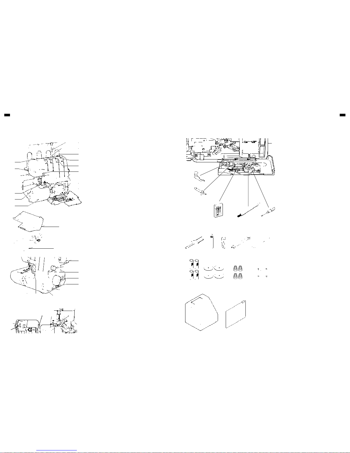
17
16
20
21
22
23
24
25
26
18 19
27
28
29
WORKING TABLE OPENED
1
2
3
5
4
15
5
6
7
8
9
10
11
12
13
16
14
1. Foot pressure regulator
2. Sewing light
3. Presser foot lever
4. Needle plate
5. Presser foot
6. Overedge cutting width dial
7. Working table
8. Thread guide pole
9. Left needle thread tension control
10. Right needle thread tension control
11. Lower looper thread tension control
12. Upper looper thread tension control
13. Needle thread guides
14. Two thread convertor instruction
15. Threading chart
16. Lint tray
17. Foot control
18. Release lever
19. Foot release lever
20. Spool disc
21. Stitch length dial
22. Differential feed control lever
23. Hand wheel
24. Plug connector socket
25. Light and power switch
26. Front cover
27. Moving cutter
28. Upper looper
29. Lower looper
30. Stitch finger (A) (See page 10)
1. Two-thread convertor
2. Stitch finger (B) (See page 10)
3. Needle set
4. Brush
5. Screw driver (small)
6. Screw driver (large)
7. Oiler
8. Moving cutter
9. Spanner
10. Tweezers
11. Thread net
12. Spool disc
13. Spool holder
14. Spool cap
15. Accessory bag
16. Machine cover
2
1
4 5
16
6 7 8 9
11 12 13 14
15
10
3
MACHINE OVERVIEW AND INSTALLATION
DETAILS OF THE MACHINE ACCESSORIES
30
All rights reserved
For technical and product improvement reasons,
the sewing computer's features, parts and
accessory are subject to unannounced changes
and alterations at any time. The accessory included
can differ from country to country.
Page 4
6 7
MACHINE OVERVIEW AND INSTALLATIONMACHINE OVERVIEW AND INSTALLATION
SETTING UP YOUR MACHINE
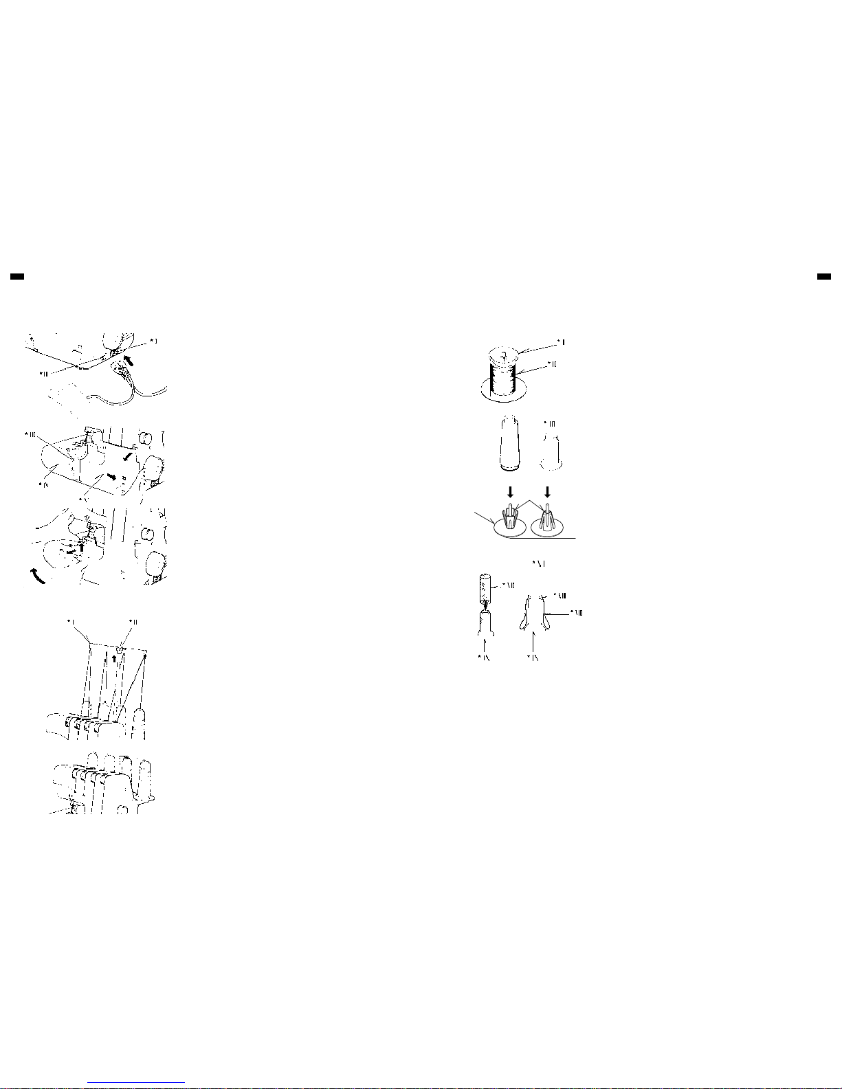
1. Wipe off excess oil in the needle plate and bed areas.
2. Foot Control
Push foot control plug into connector socket, and connect the power line
plug into power supply outlet.
3. Power / Light Switch
Your machine will not operate unless the power/ light switch is turned on.
This same switch controls both machine power and sewing light.
When leaving the machine unattended, or servicing the machine, remove
the power line plug from supply outlet.
4. Opening Front Cover
To open front cover, pull it to the right and down towards you.
5. Opening Working Table
To open working table, pull the release lever towards you with your right
hand, and lift the front of presser foot up with your left hand.
PREPARATION FOR THREADING
Thread Guide Pole
pole to the highest point until you hear it click. Place thread spools on pins and
draw thread through thread guides on the pole from rear to front.
Thread guide of pole can hold thread spools on the spool stand by pulling
down the pole as illustrated.
SPOOL CAPS FOR DOMESTIC TYPE SPOOLS
SPOOL DISC AND SPOOL HOLDERS FOR CONE SPOOLS
For large cone spools use the spool holders with the wide end at the top, and
for small ones, use the same spool holders but with the narrow end at the top.
SPOOL NETS
Polyester or bulky nylon threads become loose while unwinding. To keep
consistent feeding of such threads, utilize spool net sleeving over the spool.
MACHINE SETUP
Illustration
I. Connector socket
II. Power/light switch
III. Release lever
IV. Working table
V. Front cover
Illustration
I. Thread guide
II. Thread guide pole
Illustration
I. Spool cap
II. Domestic cotton reel
III. Cone type thread
IV. Spool holder
V. Spool disc
VI. Thread comes off the top
VII. Net
VIII. Turn up
IX. Spool
Page 5
8 9
OPERATING INSTRUCTIONMACHINE OVERVIEW AND INSTALLATION
A
E
J
B
B
K
C
G
F
H
D
D
LINT TRAY
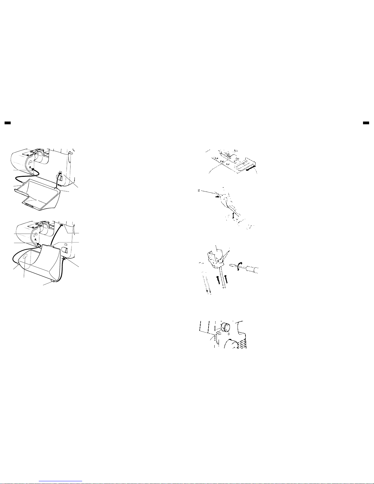
When attaching the lint tray onto the position where it may collect scraps of
fabric, insert the projection (B) into the upper hole (A) and the projection (D)
into the hole (C) at the same time.
When storing the lint tray onto the machine after completion of work,
1. Insert the projection (B) into the lower hole (E) and release lever (J) into the
hole (K) at the same time,
2. Insert the projection (D) into the hole (H) and the projection (G) into the
hole (F).
*I
*II
*III
CHANGING NEEDLE
Raise needle bar to its highest point by turning hand wheel towards you, but
leave presser foot down. Loosen needle clamp screw to remove the needle,
and place new needle with Flat Side Away From You, into the needle bar as
far as it will go, and tighten screw.
CUTTING WIDTH GAUGE
When using cutting width gauge, the fabric is cut down and sewn at same
distance from the edge of fabric within the distance of the width adjuster.
CHANGING PRESSER FEET
Be sure needle is in the up position. Raise presser foot lever.
1. Push foot release lever to remove the foot.
2. Place the desired foot on the needle plate aligning needle holes.
3. Lower the presser foot lever and push foot release lever so that the foot
holder snaps on the foot.
BASIC OPERATING PROCEDURES
OPERATING INSTRUCTION
ADJUSTMENTS AND SETTINGS
STITCH LENGTH
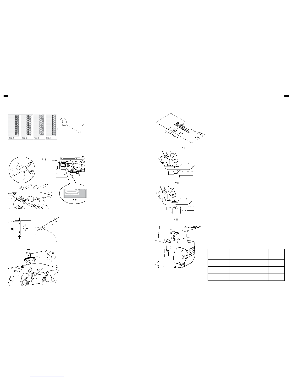
Turn the stitch length dial until the required length is obtained.
The higher the number, the longer the stitch. This dial can adjust the stitch
length from 1 to 5 mm all so on Position P and R.
Illustration
I. Foot release lever
II. Needle clamp screw
III. Flat side away from you.
IV. Stitch length dial
IV
Page 6
10 11
OPERATING INSTRUCTIONOPERATING INSTRUCTION
Overedge cutting width can be adjusted from 4 to 7
mm by simply turning overedge cutting width dial
according to the kind of fabric.
It is set at standard width of 6 mm when delivered
from the factory.
Turn it towards “5” if fabric edge curls while sewing.
(Fig. 1)
Turn it towards “7 “ if loops hang off the edge. (Fig.
2)
Loops may hang off the edge, when you sew with
lightweight fabric using 3 threads (right needle
only), and setting cutting width dial at 4 - 5 (Fig. 3).
In such a case change the stitch finger (A) to (B) to
get neat stitching (Fig. 4).
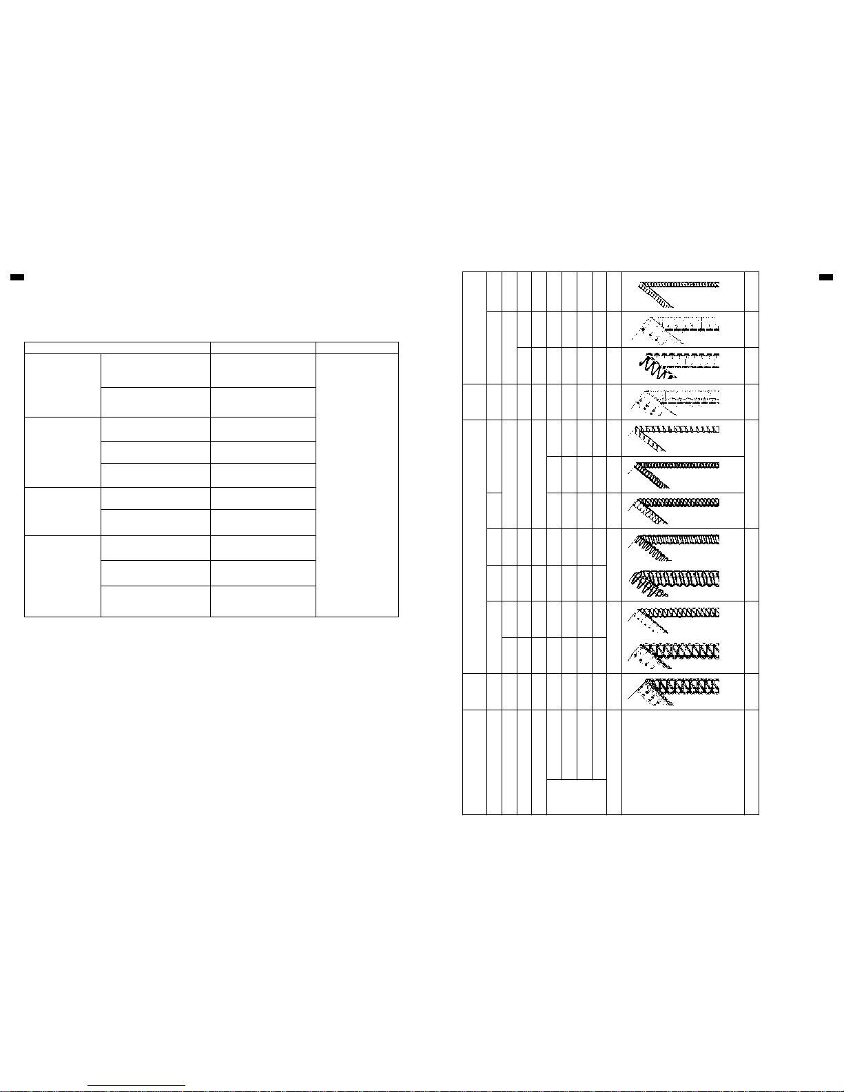
The differential feed has two independent feed dogs, one front (A) and one rear
(B).
Each feed dog has an individual feed mechanism which enables the feeding of
material at a different ratio.
DIFFERENTIAL FEEDADJUSTING OVEREDGE CUTTING WIDTH
STITCH FINGER (B)
FOOT PRESSURE REGULATOR
Presser foot pressure has been correctly set at the
factory, so you do not need to adjust it for most of
ordinary sewing. If adjustment is necessary, turn
the foot pressure regulator to higher number to
increase or to lower number to decrease pressure.
SEWING WITH EXTRA HEAVYWEIGHT FABRIC OR MULTIPLE LAYERS OF FABRIC
A wide range of fabric can be overlocked on this
machine, but it is recommended to tighten screw as
illustrated, when sewing with extra heavyweight
fabrics or mulitiple layers of fabric. Open working
table for adjustment.
Loosen the screw when sewing with light to normal
weight fabric or turning overedge cutting width dial,
or otherwise fabric may not be well cut.
The machine is set for normal weight fabrics from
the factory.
POSITIVE DIFFERENTIAL FEED
WHEN SET FOR POSITIVE DIFFERENTIAL FEED, the front feed dog (A)
makes a longer stroke than the rear feed dog (B).
This has the effect of accumulating material under the presser foot to offset the
wavering on the fabric.
NEGATIVE DIFFERENTIAL FEED
WHEN SET FOR NEGATIVE DIFFERENTIAL FEED, the front feed dog (A)
makes a shorter stroke than the rear feed dog (B).
This has the effect of stretching material under the presser foot to offset the
puckering on the fabric.
SETTING DIFFERENTIAL FEED
Set by simply moving the differential feed control lever in the direction desired
referring to the chart below.
The adjustment can be made between 0.7 (negative effect) and 2 (Positive
effect). These settings give the best ratio of feeding.
For normal sewing, the lever should be set at 1.
The lever can be reset even while sewing.
EFFECT AND
APPLICATION
TYPE OF FEEDING SETTING
FEED RATIO
REAR/FRONT
Waver-free seams,
Gathering
Positive differential feed 1-2 |-----------|----------------|
No differential feed Neutral feed 1 |--------------|-------------|
Pucker-free seams Negative differential feed 0.7-1 |-----------------|----------|
Illustration
V. Increase
VI. Decrease
VII. Tighten
VIII. Loosen
IX. Screw
Illustration
II. Overedge cutting width dial
III. Stitch finger (B)
IV. Cross section
Illustration
I. Differential feed dogs
II. Positive differential feed
III. Negative differential feed
IV. Differential feed control lever
IV
V
VII VIII
IX
VI
Page 7
12 13
OPERATING INSTRUCTION
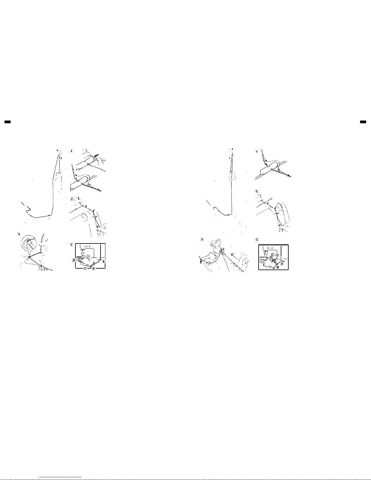
Use HA × 1SP, HA × 1(130/ 705H) Needles.
Synthetic threads are recommended for ordinary overlocking. Polyester thread, for example, is very
useful for different types of fabric.
NOTE :
Keep in mind that the lower and upper loopers will use about twice the amount of thread as the needles.
When purchasing thread for sewing, therefore, especially if it is an unusual colour, you should buy
sufficient for your requirements.
Fabric Thread Needle
Cotton Linen
Light weight:
Organdy, Lawn, Gingham Cotton No. 100
No. 90 (14)
for general sewing
No. 75 (11)
for light weight fabrics
Heavy weight:
Oxford, Denim, Cotton Gaberdine
Polyester No. 60 - 50
Cotton No. 60
Wool
Light weight:
Tropical, Wool, Poplin
Polyester No. 80
Cotton No. 60
Serge, Gaberdine, Flannel Polyester No. 80 - 60
Cotton No. 60
Heavy weight:
Velours, Camelhair, Astrakhan
Polyester No. 60 - 50
Cotton No. 60
Syntetic Fibre
Light weight:
Georgette Crepe, Voile, Satin
Polyester No. 100 - 80
Cotton No.120-80
Heavy weight:
Taffeta, Twills, Denim
Polyester No. 60
Cotton No. 60
Knit
Tricot Polyester No. 80 - 60
Cotton No. 80-60
Jersey Polyester No. 60 - 50
Cotton No. 60
Wool
Polyester No. 60 - 50
Bulk Nylon
NEEDLE AND THREAD MATCHING
NEEDLE AND THREAD
NEEDLE - THREAD SELECTION TABLE
NOTE:
The above settings of tension and overedge cutting width dial are for general guidance. A
little fine tuning will improve your stitching in many cases. Following advice helps you.
1. Turn overedge cutting width dial. (See page 10)
2. Adjust needle tensions when you sew thin or thick material.
3. Reduce the tension when you use thick thread.
4. Incorrect tension setting causes stitch skipping. Adjust the tension setting.
5. Tension setting will have problem when needle setting is incorrect.
Try test-sewing with a piece of fabric you are going to use and find the best settings.
Number of threads 4 3 3 2
Overedge cutting width dial
-
6
-
6 4
- -
5
-
4 4
-
6 6
-
6
-
4
-
6
Needle to use
Left and
Right
Left Right Left Right Right
Left and
Right
Left Right
Stitch finger
● ● ● ● ● ● ● ●
Two thread convertor
● ● ● ●
Tension
control
Left needle thread
-
4
- -
4
- -
0
- - - - - -
4
-
0
- -
4
- -
Right needle thread
-
4
- - -
4
- -
0
- -
4
- -
4
- -
4
- -
4
- - - -
5
Upper looper thread
-
4
- -
4
- -
4
- -
4
-
4
-
4
- -
4
- -
4
- - - - -
Lower looper thread
-
4
- -
4
- -
4
-
7
-
7
-
0
- -
4
- -
4
-
0
- -
4
-
0
-
1
-
Stitch length control
2.5
-
3.5 2.5
-
3.5 3
-
5 2
-
2.5
-
R
- -
P
-
2.5
-
3.5 2.5
-
3.5 2
-
3.5 1
-
2
Ref. No.
1A 2A 3A 4A 5A 6A 7A 8A 9A 10A 11A 12A
4-Thread
Overlovk
3-Thread Overlock
3-Thread Flatlock
Narrow
hem
Rolled hem
Picot
stitch
Super
Stretch
2-Thread
Flatlock
2-Thread
wrapped OL
Rolled hem
Reference page
20 18 23 19 18 18, 20 23 18, 19
Page 8
14 15
SERGER / OVERLOCK STITCH FORMATIONSSERGER / OVERLOCK STITCH FORMATIONS
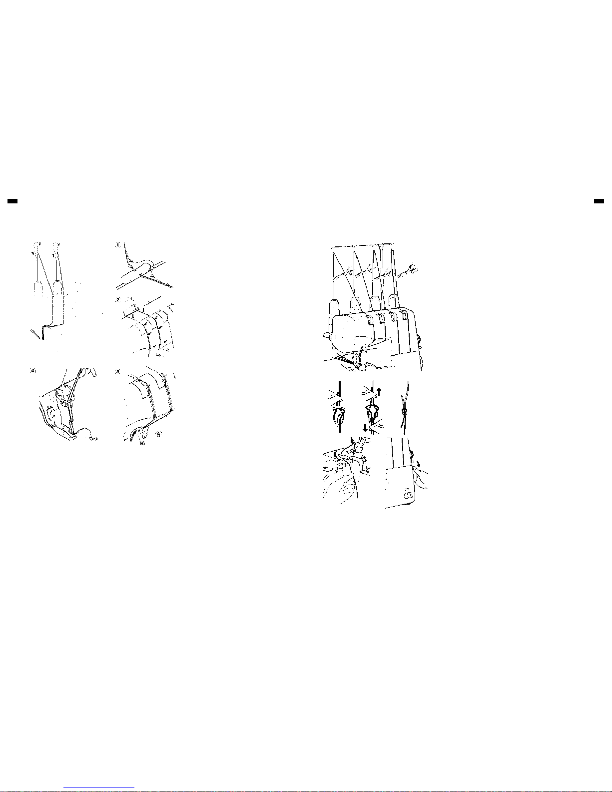
Wrong threading may cause skipped stitches,
breaking threads, or other problems.
Try to master the correct threading before moving
on to test sewing. Threading must be carried out in
the sequence of Lower Looper-Upper LooperNeedle.
Open the front cover and the working table. Raise
needle to its highest point by turning hand wheel
towards you, and raise the presser foot.
Before re-threading lower looper, remove thread
from needle eye first, then re-thread the lower
looper. This will prevent tangling.
NOTE:
Thread tension is released when the presser foot is
lifted up.
THREADING LOWER LOOPER
1. Feed the thread through the thread guide as
illustrated
2. Pull the lower thread through tension slot.
Holding the thread with your left hand, pull down
with right hand firmly.
3. Draw the thread through thread guide as
illustrated.
4. Pass the thread through lower looper eye, and
hook it around part (I) as indicated by the
arrow. Leave about 4” (10 cm) extra thread.
SERGER / OVERLOCK STITCH FORMATIONS
THREADING
THREADING UPPER LOOPER
1. Feed the thread through the thread guide as
illustrated.
2. Pull the upper thread through the slot. Holding
the thread with your left hand, pull down with
right hand firmly.
3. Draw the thread through the thread guide as
illustrated. When threading according to the
instruction, upper looper thread pass the thread
guide (A) automatically after rotating hand
wheel.
4. Pass the thread through wire thread guide and
looper eye, leaving an excess length of about 4”
(10 cm).
I
Page 9
16 17
SERGER / OVERLOCK STITCH FORMATIONSSERGER / OVERLOCK STITCH FORMATIONS
THREADING NEEDLES
1. Feed the thread through the thread guide as
illustrated.
2. Draw the needle threads through tension slot.
Holding the thread with your left hand, pull down
with right hand firmly.
3. Draw the thread through the thread guide as
illustrated.
4. Thread the needles from front to back through
needle eye and pull the threads towards the
back passing along the right side of presser
foot, leaving an extra length of about 4” (10 cm).
REPLACING THREAD SPOOLS
When replacing thread spools, the following steps may be helpful for quick
changeover.
1. Cut off existing threads near the spools. Tie the cut ends thread from new
spools as illustrated (seamen’s knot).
2. Raise presser foot
3. Lower needle bar to its lowest position by turning hand wheel AWAY FROM
YOU. Carefully pull the existing threads until the connecting knots pass
through needle eye and looper eyes.
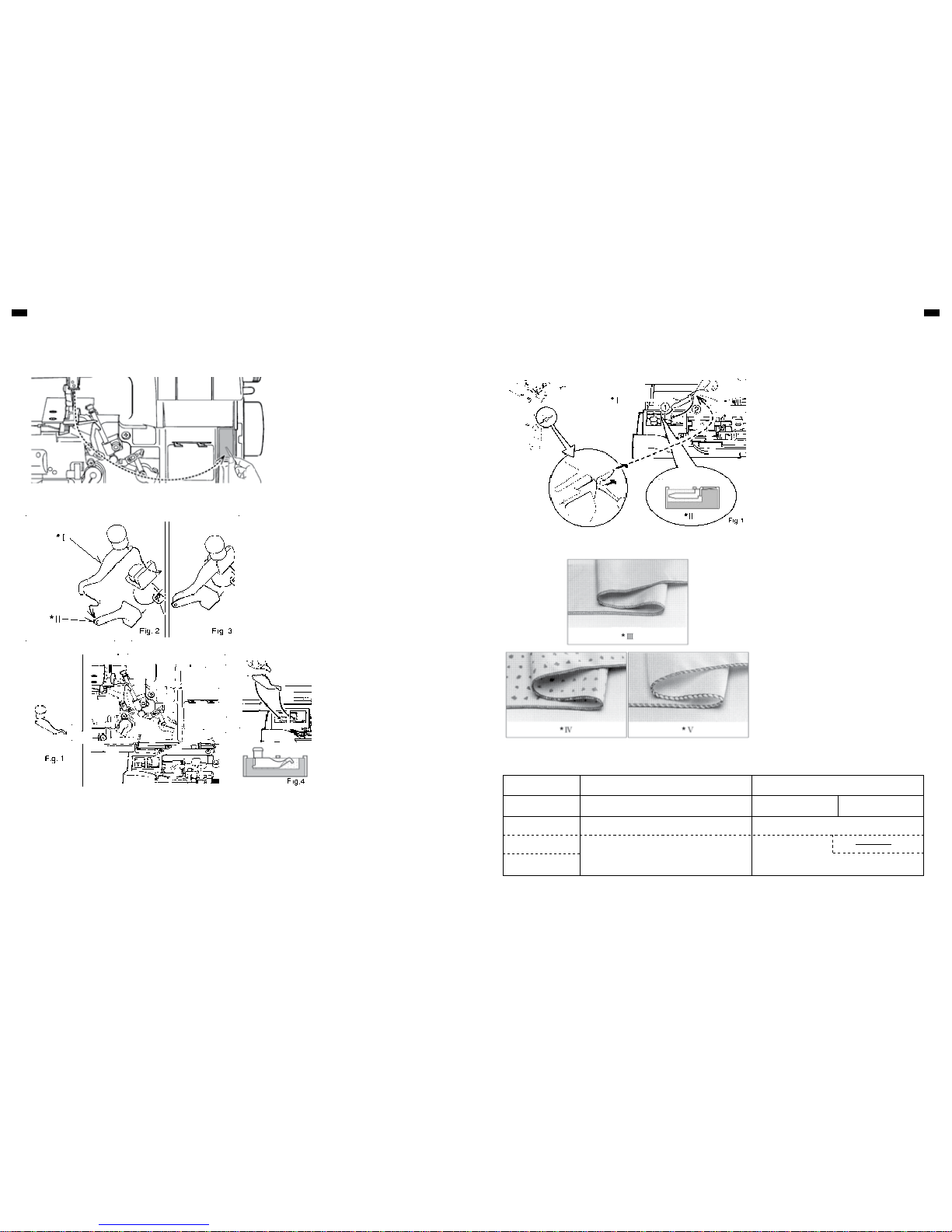
HELPFUL HINTS
CUTTING NEEDLE THREAD
Frayed thread may make needle threading difficult. Draw the thread near the
thread cutter on the needle plate and push the thread cutter lever or draw the
thread passing under the moving cutter and turn hand wheel towards you to
obtain clear cut end as illustrated.
A
B C
Page 10
18 19
SERGER / OVERLOCK STITCH FORMATIONSSERGER / OVERLOCK STITCH FORMATIONS
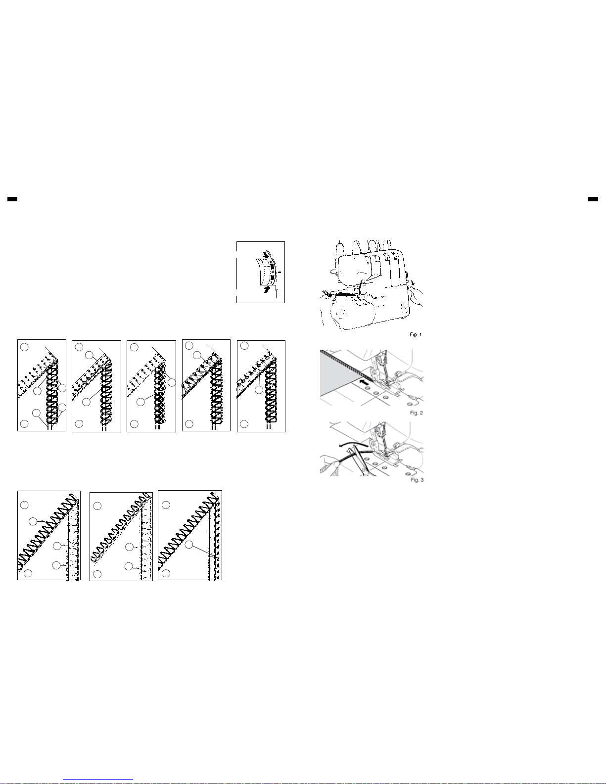
By threading the LEFT needle only a
width of 6 mm will be produced and by
threading the RIGHT needle only a
width of 3.8 mm will be produced.
Please keep the unused needle on the
needle pad as illustrated.
THREE-THREAD OVERLOCK WITH ONE NEEDLE
CONVERTING TO TWO-THREAD USE
To convert to two thread use, first open
the front cover and working table and
raise needle to its highest point by
turning hand wheel towards you.
Remove the right needle and use the
left needle.
Please keep the unused needle on the
needle pad.
Pull out the converter as shown in Fig.
1.
Attach the two-thread converter onto
the upper looper as shown in Fig. 2,
Fig. 3, making sure that you slide tail
end in first (A) then locate hook end into
looper hole (B).
When not using converter, insert it deep
and keep as illustrated in Fig. 4.
Narrow overlock edge Rolled edge
with Three Threads with Three Threads with Two Threads
Thread for needle
Polyester, Nylon, Silk No. 50-100 Nylon No. 100
Upper looper
Polyester, Nylon, Silk No. 50-100
Bulk nylon (less stretchable)
Lower looper
Bulk nylon (less stretchable)
Narrow and rolled edge is ideal for use on thin
materials such as georgette crepe, crepe de chine,
silk etc.
Also, picot stitch can be produced particularly when
sewing on fine ‘scarflike’ materials. In view of the
nature of these hems, they are unsuitable for use
on ‘hard’ or ‘heavy’ materials.
1. Raise the presser foot.
2. Open the front cover and working table.
3. Remove the stitch finger from the needle plate
by screw driver and keep it in the front cover as
illustrated or in the accessory bag.
4. Set the machine according to page 21.
NOTE:
1. Please use following recommended thread for
making ideal seams.
2. After finishing, re-set the stitch finger in its
place. Please ensure inserting it deep as
illustrated in Fig 1.
NARROW, ROLLED HEM AND PICOT STITCH
RECOMMENDED THREAD
Illustration
I. Two-thread overlock convertor
II. Upper looper
Illustration
I. Stitch finger (A)
II. Cross section
III. Narrow hem
IV. Rolled hem
V. Picot stitch
A
B
D
C
Page 11
20 21
SERGER / OVERLOCK STITCH FORMATIONS SERGER / OVERLOCK STITCH FORMATIONS
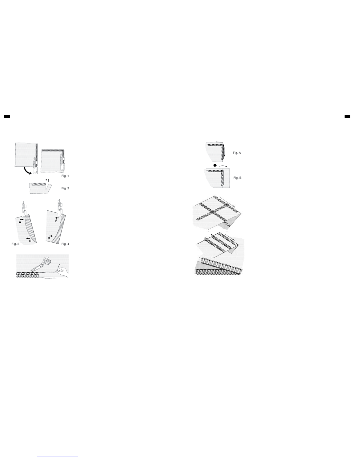
ADJUSTING THREAD TENSIONS
Turning tension dial to a higher number gives a tighter thread tension. Turning
tension dial to a lower number gives a looser thread tension. The higher the
number, the tighter the tension.
Test thread tensions on a scrap you plan to use.
Decrease tension
Increase tension
TWO-THREAD USE
Just right. Lower looper thread pulled to
under side.
Fig. 1 Fig. 2
Needle thread pulled to top side.
Decrease needle tension. Increase needle thread tension.
FOUR-THREAD USE
Fig. 1
Just right.
1 Under side
2 Top side
3 Upper looper thread
4 Lower looper thread
5 Right needle thread
6 Left needle thread
7 Needle thread
Fig. 2 Fig. 3
Upper looper thread
pulled to under side.
Lower looper thread
pulled to top side.
Increase upper looper
thread tension and/ or
decrease lower looper
tension.
Increase lower looper
thread tension and/or
decrease upper looper
tension.
Fig. 4 Fig. 5
Left needle thread loose
and visible on under
side of fabric.
Right needle thread
loose and visible on
under side of fabric.
Increase left needle
thread tension and/or
decrease either or both
looper threads.
Increase right needle
thread tension.
After threading is completed, use a scrap of fabric that you plan to sew and test
to sew in the following order.
1. Gently pulling all the threads to the left, lower the presser foot. Rotate the
hand wheel towards you a few times to see if the lock stitches are properly
formed.
2. Start the machine at low speed and feed in test fabric under the presser
foot by slightly pushing it forward. (This can be done with the presser foot
down on most fabrics except bulky materials).
Guide the fabric gently as machine automatically feeds the material.
3. Check thread tensions by test sewing on spare fabric. (See page 13)
4. At fabric end, carry on running machine at low speed, gently pulling the
fabric towards the back, until about 5 to 6 cm of extra lock stitches are
produced without fabric.
Cut thread by with scissors.
TRIAL SEWING - SERGER / OVERLOCK
1
1
1
1
1
1 1
1
3
33
5
4
4
4
4
4
6
7
7
7
6
2
2
2
2
2 2 2
2
5
7
Page 12
22 23
PRACTICAL SEWINGPRACTICAL SEWING
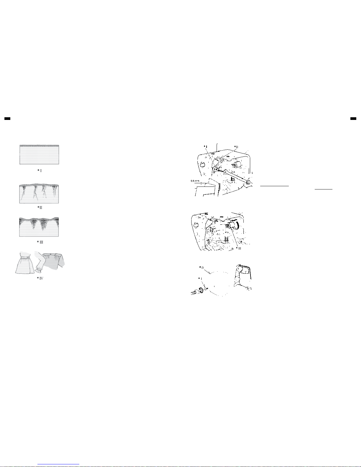
TURNING OUTSIDE CORNERS WITHOUT CUTTING THREADS
1. When you reach the fabric edge, stop stitching with the needle above the
fabric.
2. Raise the presser foot and gently pull on the thread chain just enough to
clear the stitch finger.
3. Turn the fabric, lower the presser foot and begin stitching in the new
direction. Fig. 1.
NOTE:
When overlocking and trimming at the same time, cut the fabric along the new
stitching line for about 3 cm, before turning the fabric. Fig. 2.
TURNING CURVED EDGES
For inside curves, guide fabric gently with trimming line of the fabric under the
right front of the presser foot (or a little to the left), applying pressure at point A
in the direction of the arrow with your left hand, and at the same time applying
a little opposite pressure at point B with your right hand. Fig. 3.
For outside curves place under the presser foot in a similar manner but
applying the pressure in the opposite directions. Fig. 4.
REMOVING STITCHES FROM SEWN FABRIC
To remove stitches already sewn, snip off needle thread(s) at intervals and pull
out looper thread(s).
PRACTICAL SEWING
BASIC TECHNIQUES
In addition to normal overlocking which is fully described in this instruction
book, your machine can also be used for a number of decorative applications
such as decorative top-stitching, butted seams, pin-tucking or making lengths
of decorative braid. See below.
Decorative top-stitching – using only two threads or using three threads
(flat seam)
Fold fabric along the line to be top-stitched and sew over the folded edge,
making sure not to cut into the fold. Fig. A.
Unfold the fabric, pull the ends of the threads to the underside and press flat.
The final appearance can be enhanced by using buttonhole twist or embroidery
thread on the lower looper.
Butted seams – using only two threads or using three threads (flat seam)
Place two pieces of fabric wrong sides together and overlock along the edge.
Unfold and press.
By using different coloured fabrics and thread a pleasing ‘patchwork’ effect can
be achieved.
Pin-tucking – using three threads
Fold fabric along a line to be pin-tucked and overlock sew along the folded
edge, making sure not to cut into the folded edge of the fabric. (See page 25).
Pull ends of threads to the underside and press.
Making decorative braid – using three threads
Overlock over a cord or braid, holding it carefully with both hands, making sure
not to cut the edge. (See page 25).
NOTE :
* If you use blind hem foot (See page 28), decorative stitch is made easily.
** Reduce the upper looper tension when you use thick thread.
DECORATIVE EFFECTS
Illustration
I. Cut!
Page 13
24 25
MAINTENANCEPRACTICAL SEWING
Please refer to page 11 DIFFERENTIAL FEED.
Differential feed is designed to minimize puckering and wavering. It is also very
effective for gathering.
1. Puckering
Puckering tends to occur on woven or sheer fabrics. To obtain pucker-free
seams, set the differential feed control dial at less than 1.
2. Wavering
Wavering tends to occur on knitted or stretchable fabrics. To obtain waverfree seams, set the differential feed control dial at more than 1.
3. Gathering
Differential feed makes gathering easier on lightweight fabric. Use it on
waistlines, sleeve heads, sleeve bottoms and ruffles, etc.
Set the differential feed control dial between 1.5 and 2 to obtain the best
gathering effect for your use.
NOTE
The exact adjustment depends on the thickness and elasticity of fabric. Even
the stitch length can influence the setting. The longer the stitches, the more the
fabric is contracted.
Always do a test run with a piece of actual fabrics you use and find the best
settings.
DIFFERENTIAL FEED APPLICATIONS REPLACING MOVING CUTTER
DISENGAGING MOVING CUTTER
REPLACING THE SEWING-LIGHT BULB
MAINTENANCE
Replace a moving cutter if it becomes blunt as follows. A spare cutter will be
found in your accessories.
NOTE:
You should not need to replace fixed cutter, which is made of a special hard
alloy material.
FIRST REMOVE THE POWER PLUG FROM THE SUPPLY SOCKETOUTLET.
1. Loosen screw and take out moving cutter.
2. Close the working table. Lower cutter driving arm to its lowest position by
turning the hand wheel towards you by hand. In this position, set
replacement cutter in position and secure it with screw, ENSURING THAT
THE EDGE OF THE MOVING CUTTER IS APPROXIMATELY 0.5 MM
BELOW THE SURFACE OF THE FIXED CUTTER.
If you want to sew without cutting, open the working table and disengage the
moving cutter by pushing the cutter release knob to the left and turning it
towards you as illustrated.
Ensure that fabric edge is not wider than overedge width selected or upper
looper and needle can be damaged.
Switch machine off before removing the face cover.
Remove screws and face cover as illustrated. Push thermal screen aside to
access the bulb. Unscrew and remove defective bulb. After replacing the bulb,
push thermal screen back into its basic position. Refit face cover and retighten
screws.
Illustration
I. Screw
II. Moving cutter
III. Cutter release knob
IV. Face cover
Illustration
I. Pucker or waver-free seams
II. Puckering
III. Wavering
IV. Gathering
Page 14
26 27
MAINTENANCEMAINTENANCE
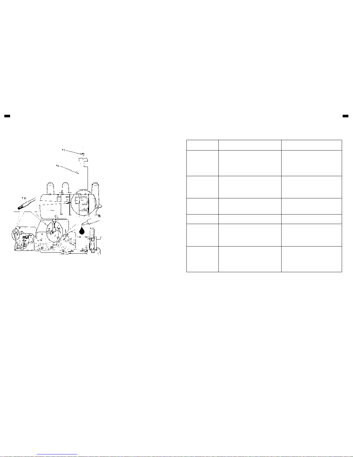
CLEANING AND LUBRICATING
To keep the machine running smoothly, keep it
clean and lubricated at all times.
FIRST DISCONNECT MACHINE FROM POWER
SUPPLY BY REMOVING PLUG FROM SOCKETOUTLET.
1. Open the front cover and working table. Using
the brush provided, remove dust and lint that
have accumulated.
2. Apply a few drops of oil to the points indicated
by arrows.
ALWAYS USE A GOOD QUALITY Overlock
machine OIL.
3. Remove front cover with screw driver and
remove dust and lint of inside with the brush.
PROBLEM PROBABLE CAUSE CORRECTION
Irregular Stitches
Incorrect Thread Tension(s).
Incorrect size Needle.
Improper Threading.
Pulling Fabric.
Loose Presser Foot.
Reset Thread Tension(s).
Choose correct size Needle for Thread and
Fabric.
Re-thread Machine.
Do not pull Fabric; guide it gently.
Reset Presser Foot.
Breaking Needle
Pulling fabric.
Incorrect size Needle.
Incorrect setting of Needle.
Loose Presser Foot.
Do not pull Fabric; guide it gently.
Choose correct size Needle for Thread and
Fabric.
Reset Needle.
Reset Presser Foot.
Puckering
Incorrect Thread Tension(s).
Bent or blunt Needle.
Differential feed is set incorrectly.
Reset Thread Tension(s).
Insert new Needle.
Set it at less than 1.
Wavering Differential feed is set incorrectly. Set it at 1 or at more than 1. for knitted fabrics.
Skipping Stitches
Incorrect size Needle.
Improper Threading.
Bent or blunt Needle.
Incorrect setting of Needle.
Re-thread Machine.
Choose correct size Needle for Thread and
Fabric.
Insert new Needle.
Reset Needle.
Breaking Threads
Improper Threading.
Bent needle.
Thread Tension(s) too tight.
Incorrect setting of Needle.
Thread Spool tangled.
Thread Guide Pole not extended.
Re-thread Machine.
Insert new Needle.
Reset Thread Tension(s).
Reset Needle.
Reset Spool properly.
Fully extend Guide Pole.
TROUBLESHOOTING GUIDE
Illustration
I. Screw
II. Front cover
III. Brushing
IV. Oil
Page 15
28 29
OPTIONAL ACCESSORIES OPTIONAL ACCESSORIES
OPTIONAL ACCESSORIES
BLIND HEM FOOT ELASTICATOR
PIPING FOOT
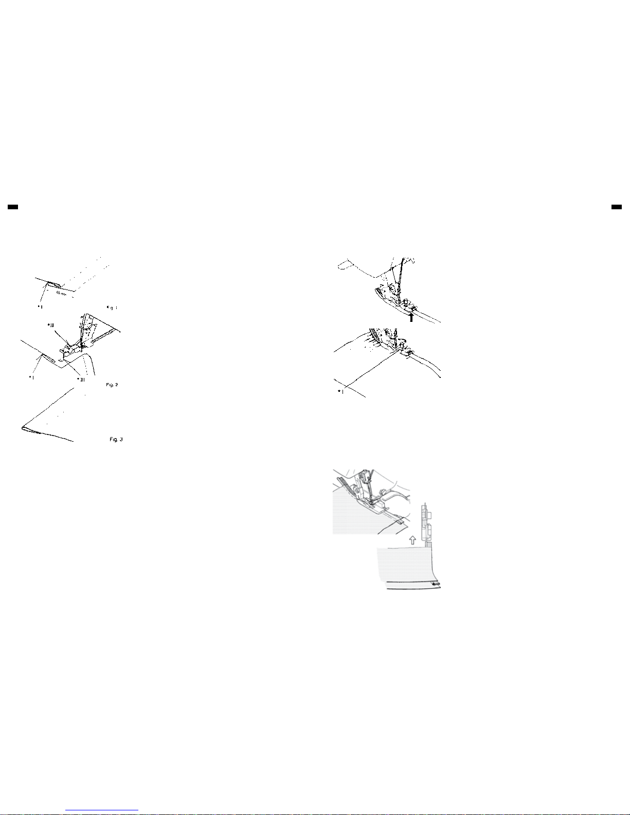
Blind hem feet are obtainable as an optional extra and are available in two
sizes. 0.5 for fine/medium fabrics and 1.0 for medium/heavy fabrics.
Fit the appropriate foot.
Set the stitch length 4 - 5.
Now proceed as follows:
1. Turn up the hem to the required depth and press. Fold the hem back
against the 'right' side of the garment, creating a 'soft' fold on the 'wrong'
side of the fabric – see Fig. 1.
2. Place fabric under the presser foot with the 'wrong' side up. Feed the folded
edge through the guide in the front of the foot and lower the presser foot
lever. Try a stitch (or several stitches) on a spare piece of the actual fabric,
and adjust the guide so that the needle just catches the fold. Adjust the
guide by means of the small screw on the top of the foot – see Fig. 2.
3. When correctly set, sew the hem. The outside edge will be cut away by the
machine – see also Fig. 2. After completion, open out and press again. The
stitches should be almost invisible on the 'right' of the fabric – see Fig. 3.
An elastic foot is available as an optional extra. This foot will guide your elastic
and at the same time apply pressure to the lastic with our specially designed
tension controlled roller, llowing you to control the elasticity while sewing.
1. Replace regular foot with elasticator.
2. Set stitch length at about 4.
3. Slightly raise the roller portion of the foot and insert elastic tape between
the roller and the lower support bar as illustrated, until the edge of elastic
reaches the feed dog teeth.
4. Sew the elastic for about one inch (3 cm) or more to confirm if the tape is
properly sewn.
5. Insert the fabric under the foot and sew together with the elastic.
6. Check the stitches to make sure they are correct and adjust tension
(tighter) if necessary.
7. Adjust the tension control of the roller so that the desired finish can be
obtained.
█
Tighter tension of the roller gives more elasticity of the fabric after it is
sewn.
█
Weaker tension of the roller gives less elasticity of the fabric.
8. When the right side of elastic is not even with right side of fabric, remove
the stitch finger (A) or change it to stitch finger (B). Decrease the number of
overedge cutting width dial. Three threads overlock with right needle or left
needle is recommendable in accordance with the size of elastic.
Prepare a piece of ready-made piping (corded bias fold tape). Place folded
piping between seam edges with fold extending beyond seam line toward
garment. Pin or baste, and stitch the seam.
Braid or ribbon may also be used, either flat or folded braid can be used in
straight seams.
Use for decorating edges of collars, cuffs, pockets, etc.
Illustration
I. Final hem length
II. Screw
III. Guide Illustration
I. Tension control of roller
Page 16
30 31
OPTIONAL ACCESSORIESOPTIONAL ACCESSORIES
PEARL FOOT GATHERING/SHIRRING FOOT
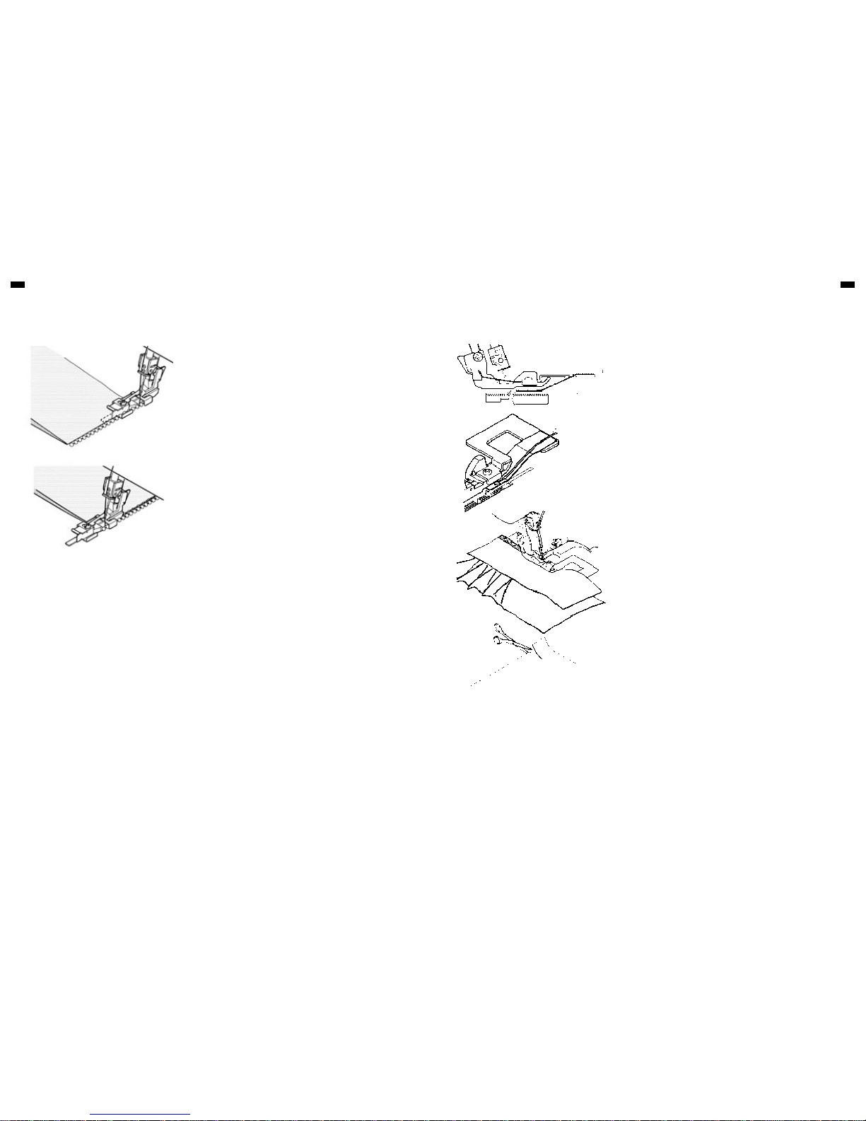
1. PEARLS ALONG AN EDGE:
█
Set for left needle (remove right needle) 3-thread overlock.
█
Set tensions as follows:
█
Left needle: 4
█
Upper looper: 1 - 2
█
Lower looper: 7 - 8
SEW:
█
Remove regular foot; replace with pearl foot.
█
Remove stitch finger as you did for a rolled edge.
█
Swing cutter away (p. 27) to lowest position, close front covers.
█
Raise the needle to it’s highest position.
█
Place pearls in the channel on the right side of the foot with 2" of pearls
extending behind foot.
█
Take one stitch with the hand wheel to secure the pearls.
█
Follow edge of fabric along fabric guide.
█
Sew pearls on edge of fabric.
█
Return cutter to original position when finished.
2. PEARLS SEWN WITH A FLAT LOCK STITCH:
FABRIC:
█
Medium weight woven 2 or 4 mm pearls
█
Set for a 3-thread flat lock, left needle only. See pg. 13
SEW:
█
Remove regular foot; replace with pearl foot.
█
Insert small stitch finger.
█
Swing cutter (p. 27) away to lowest position.
█
Raise needle to it’s highest position.
█
Place pearls in channel on right side of the foot with 2"of pearls extending
behind foot.
█
Take one stitch with the hand wheel to secure the pearls.
█
Sew pearls on with the left needle just catching the fold of the fabric.
█
Pull flat lock open.
1. Tension settings for gathering:
█
Left needle 4
█
Right needle 4
█
Upper looper 4
█
Lower looper 4
█
Differential feed 2.0
█
Stitch length 4
2. Replace regular presser foot with gathering foot. Clip both fabric layers
approximately 5/8"(1.5 cm.) inside and 1 1/2"(4 cm.) down. Lift front of
presser foot to place fabric.
3. Place fabric to be gathered underneath the presser foot. Place fabric which
will remain straight between presser foot and lower metal piece. Push
clipped portion through slot in foot. Lower presser foot.
4. Turn handwheel to make 4 - 5 stitches in the fabric, making sure to catch
both upper and lower layers.
5. Serge. Use both hands to guide fabric, one on the under layer of fabric.
Keep in mind that the lower piece of fabric will move faster as it is gathering
than the top piece.
* I
* II
* I
* II
Illustration
I. Fabric to be straight
II. Fabric to be gathered
Page 17

13/04 EN 502070.00.36 / 82369
 Loading...