

Page 1
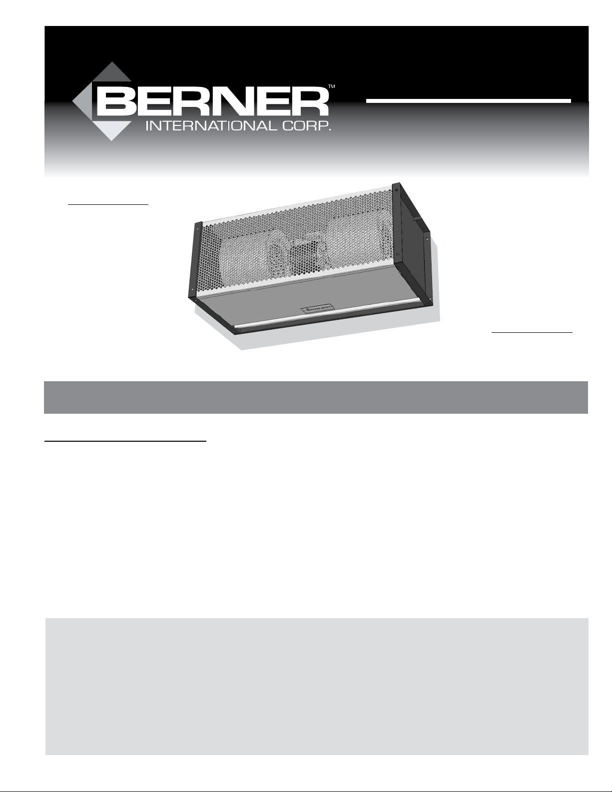
VSA/VSB
AIR DOOR
Made in the USA
READ AND SAVE
THESE INSTRUCTIONS
No. II-230
Date July, 2008
KSA/KSB
AIR DOOR
Made in the USA
Installation & Maintenance Instructions
TABLE OF CONTENTS
I. UNCRATING.................................................................................................................................................................. 2
II. MOUNTING INSTRUCTIONS ..................................................................................................................................... 2
III. WALL MOUNTING ..................................................................................................................................................... 3
IV. SUSPENDED MOUNTING ........................................................................................................................................ 4
V. VERTICAL MOUNTING .............................................................................................................................................. 4
VI. TANDEM MOUNTING BRACKETS ........................................................................................................................... 5
VII. ELECTRICAL CONNECTIONS ................................................................................................................................. 5
VIII. MECHANICAL CONNECTIONS ............................................................................................................................. 5
IX. AIRFLOW ADJUSTMENTS ....................................................................................................................................... 5
X. MAINTENANCE AND CLEANING ............................................................................................................................. 6
XI. SERVICE ..................................................................................................................................................................... 6
WARNING: TO REDUCE THE RISK OF FIRE, ELECTRIC SHOCK OR INJURY TO PERSONS, OBSERVE THE FOLLOWING:
A. Use this unit only in the manner intended by the manufacturer. If you have any questions, contact the manufacturer.
B. Before servicing or cleaning unit, switch power o at service panel and lock the service disconnecting means to prevent power from being
switched on accidentally. When the service disconnecting means cannot be locked, securely fasten a prominent warning device, such as a
tag, to the service panel.
C. Installation work and electrical wiring must be done by qualied person(s) in accordance with all applicable codes and standards, including
re-rated construction.
D. Sucient air is needed for proper combustion and exhausting of gases through the ue (chimney) of fuel burning equipment to prevent
back drafting. Follow the heating equipment manufacturer’s guideline and safety standards such as those published by the National Fire
Protection Association (NFPA), and the American Society for Heating, Refrigeration and Air Conditioning Engineers (ASHRAE), and local
code authorities.
E. When cutting or drilling into wall or ceiling, do not damage electrical wiring and other hidden utilities.
Page 2
I. UNCRATING
Carefully examine the carton(s) for damage before opening. If
the carton is damaged, immediately notify shipping company.
If the unit(s) were shipped on wooden skids, remove protective wood and banding straps securing the carton(s) to the
skid. Open the carton(s) and remove all protective packaging.
Immediately verify that the electrical rating nameplate located
on the cover matches electrical power supply available. Retain
the shipping carton(s) until the unit(s) is installed and properly
operating.
ACCESSORIES: If the unit(s) were ordered with optional electrical accessories (door switch, control panel, etc.), the accessories
may be found in the carton containing the unit or in a separate
carton(s) accompanying the unit(s). Check all of the cartons/
skids for accessories before discarding.
II. MOUNTING INSTRUCTIONS
(General Notes for All Mounting Congurations)
INDOOR MOUNTING - Environmental/Insect/Dust Control
OUTDOOR MOUNTING (Unheated Only) - Insect/Dust Control
A. Berner VSA and VSB Series Air Doors are designed to
be mounted by their end anges without the need for
intermediate support. Each end ange contains (8) total ½”
holes located on all (4) sides to facilitate mounting exibility
and the easy addition of mounting accessories. Units may
be attached to the wall directly, suspended from overhead,
or supported by brackets. The style of door will determine
the best mounting method and; as a general rule, use the
mounting conguration that positions the air door as close
to the top of the doorway as possible without interfering
with door operation.
B. The VSA/VSB air door is designed to be an eective barrier
against cold drafts in the winter and hot air in the summer.
To achieve optimum protection, the unit should be mounted
on the inside of the building, ush to the wall and as close
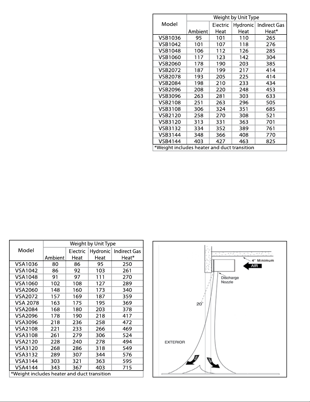
TABLE 2
to the top of the door opening as possible. To ensure peak
performance keep the air stream free of obstructions. If
the air door cannot be installed ush with the wall, be sure
to seal the gap between the wall and the back of the Air
Door along the entire length of the unit to prevent airow
through this void.
C. The air door will not perform properly if negative air
pressure exists in the building. Under these conditions,
a means for makeup air to the building must be
provided so that the air pressure on both sides of the
opening is in balance.
TABLE 1
DRAWING 1
-2-
Page 3
D. Before mounting the air door, check the supporting
structure to verify that it has sucient load-carrying capacity
to support the weight of the unit(s). The mounting hardware
(supplied by others) should be capable of supporting a
minimum of three (3) times the weight of the unit. See
Tables 1 & 2.
E. The air door is weatherproof. Therefore, no special covering
is required when outdoor mounting, unheated, steam, or
hot water units.
F. IMPORTANT: A minimum of 4” (8” preferred) is
recommended above the top of the Air Door for the
installation and removal of the screen or to gain access to
junction boxes.
G. When determining the mounting location for the unit(s),
make sure that nothing interferes with the curtain of air
developed when the discharge vanes are directed from 0º
to 20º toward the door opening. If the air stream strikes any
obstruction (the top edge of the doorway, a door opening
device, etc.), the eectiveness of the unit will be greatly
reduced. See Drawing 1.
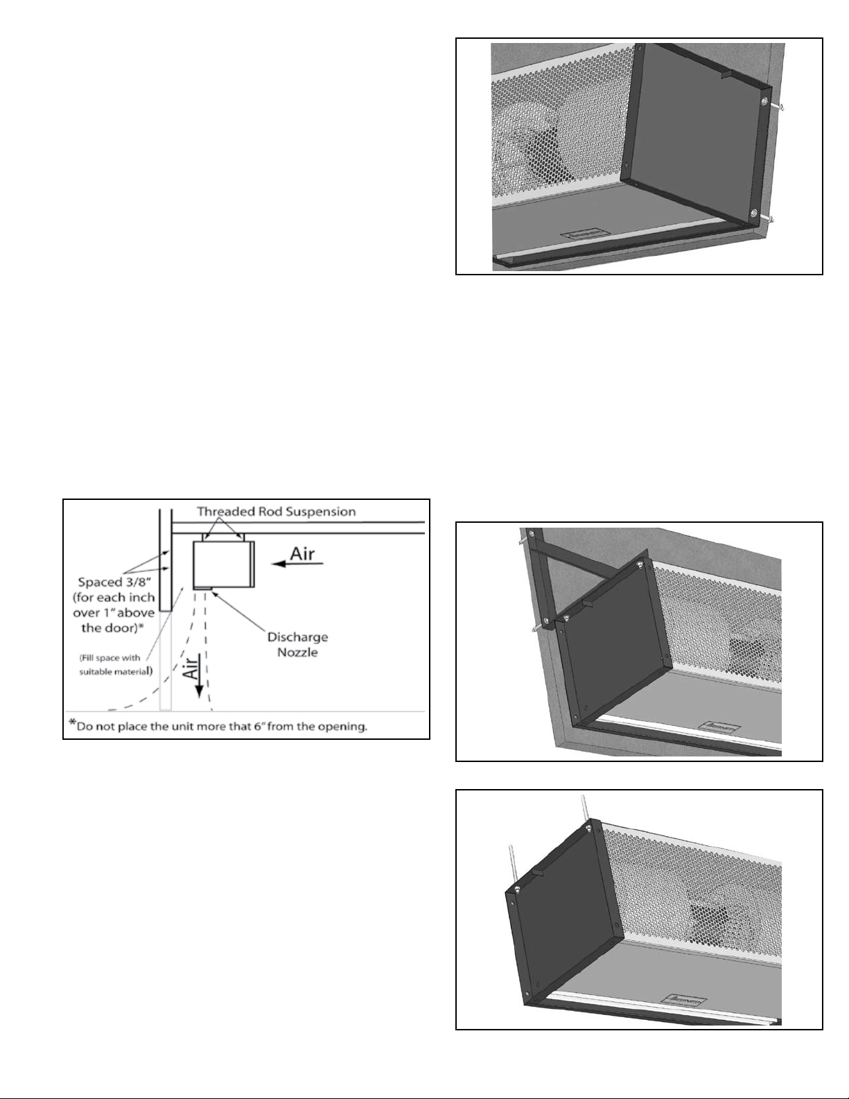
H. For optimum performance, the bottom of the unit
(discharge nozzle) should be no more than 1” above the top
of the door opening with the unit mounted ush to the wall.
If the unit must be mounted higher, it must be spaced out
from the wall ³/₈” for every inch the unit is above the door
opening. See Drawing 2.
FIGURE 1 - Wall Mounting
III. WALL MOUNTING
A. Wall mounting works well with standard hinged doors or
sliding doors.
B. The VSA/VSB series endplates are equipped with ½” holes
for wall mounting. The unit may be attached to the wall
using, at minimum, /” bolts through the holes on the back
of the endplate. See Figure 1. Or, the unit may be attached
using an optional wall mounting bracket or a combination
of extension and wall mounting brackets (available from
Berner) attached to the holes on the top of the endplate
and the wall. See Figure 2.
DRAWING 2
I. Electric heated units shall:
1. Have a minimum clearance of at least 1” between the
sides and top of the unit and any combustible material.
2. Have a minimum clearance of at least 6’ between the
bottom of the unit and the oor.
3. Be installed indoors only.
J. Proceed to one of the following sections, depending on
application and door type:
Section III: Wall Mounting
Section IV: Suspended Mounting
Section V: Vertical Mounting
Section VI: Tandem Mounting Brackets
FIGURE 2 - Wall Mounting Bracket
FIGURE 3 - Threaded Rod Suspension
-3-
Page 4

FIGURE 4 - With Extension Brackets
C. Electrical Connections - Proceed to Section VII.
IV. SUSPENDED MOUNTING
A. Suspended mounting works well with the majority of door
types commonly found in an industrial setting, such as roll
up doors, “high rise” track doors, “low-rise” turn back doors,
and “high-rise” turn back doors.
B. The VSA/VSB series endplates are equipped with ½” holes
for suspended mounting. The unit may be suspended
using a minimum /” suspension rod (Figure 3), or using
/” suspension rods and extension brackets (available from
Berner). See Figure 4.
C. Electrical Connections - Proceed to Section VII.
V. VERTICAL MOUNTING
A. Vertical mounting works well when the opening is taller
than it is wide, or when the door type prevents a typical
“over-door” mounting position.
B. Optional Floor Mounting Brackets bolt to the unit endplate,
and provide a rigid base to attach the unit to the oor. Two
Brackets are required.
FIGURE 6 - Floor Mounting
FIGURE 7 - Increased Stability
D. Position the unit vertically in its intended position and
anchor it to the oor with a minimum /” fastener.
See Figure 6.
E. To improve the stability of the installation, it is required
that the top of the unit be attached to the wall. A common
approach is to attach a minumum length of /” threaded
rod through one of the open mounting holes in the top
endplate and ax the other end of the rod to the wall.
See Figure 7.
F. Electrical Connections - Proceed to Section VII.
FIGURE 5 - Floor Mounting Brackets
C. To vertically mount a VSA/VSB unit using optional Floor
Mounting Brackets, bolt brackets on the inside of the
endplate with (4) ½ - 13 bolts as shown in Figure 5.
FIGURE 8 - Tandem Mounting
-4-
Page 5

FIGURE 9 - Tandem Mounting FIGURE 10 - Mechanical Connection - Steam/Hot Water
VI. TANDEM MOUNTING BRACKETS
(For Vertical Mount Installation)
A. Optional Tandem Mounting Brackets are used to join two
air curtains together in a vertical application when the door
height exceeds 12’.
B. Tandem Mounting Brackets connect the endplates of the
units to be joined. Two brackets are required. Ideally, the
units are joined together before the lower unit is bolted to
the oor.
C. Using (4) ½ - 13 x 1” bolts, attach the Tandem Mounting
Brackets to the inside of one of the unit’s endplates as shown
in Figure 8.
D. Slide the endplate of the next unit over the brackets installed
in Step C and attach using (4) additional ½” bolts as shown in
Figure 9.
E. Assemble Floor Mounting Brackets to lower unit and attach
to oor per steps C and D of Section V.
F. Electrical Connections - Proceed to Section VII.
VII. ELECTRICAL CONNECTIONS
All electrical wiring and connections MUST be performed
by qualied personnel in accordance with the National
Electrical Code ANSI/NFPA No. 70 (latest edition) or, in Canada,
the Canadian Electrical Code, Part 1-C.S.A. Standard C22.1 and
local codes and regulations.
A. Check the rating nameplate on the top of the unit for supply
voltage and current requirements. A separate line voltage
supply with a suitable branch circuit protection device
should be run directly from the main electrical panel to the
unit. A disconnect switch for each branch circuit is a required
part of this installation.
B. All eld wiring must be copper with a minimum insulation
of 60° C within approved conduit. If any of the wire supplied
with the unit must be replaced, it must be replaced with
copper wiring with a minimum insulation of 90° C.
C. Remove the Junction-Box cover.
D. Connect the power supply to the unit. Connect all supply
and control circuit wires according to wiring diagram
provided.
NOTE: For electric heated units provided with optional
remote thermostat: Mount and wire the thermostat
according to instructions and wiring diagram.
VIII. MECHANICAL CONNECTIONS
A. ELECTRICALLY HEATED MODELS
The heater circuit may be controlled by a remote thermostat
or manually through the switch located on the discharge
side of the unit. Overheating protection is provided by auto
reset thermal cutouts built into the heater coil assembly
(see the wiring diagram).
B. STEAM OR HOT WATER HEATED MODELS
Piping should be done in accordance with local codes,
regulations and standard practices. Connect the building
system supply and return to the MNPT nipples on the
heating coil. See Figure 10.
IX. AIR FLOW ADJUSTMENTS
A. With the air door operating and the door in its full open
position, check to see that nothing is obstructing the airow
at the discharge nozzle vanes.
B. Find the air stream split location. Hold a handkerchief by
its corners, approximately 12” above the oor. Gently move
the handkerchief back and forth in the doorway. Make sure
the air is being directed to both the inside and the outside.
See Figure 11. The split location is indicated where the
handkerchief is vertical with minimal or no uttering.
FIGURE 11 - Air Stream Split
-5-
Page 6

C. Adjust the discharge nozzle vanes so the split location is
approximately 3” outside the doorway. Adjust the speed
controller so that the split location is approximately 12”
above the oor.
X. MAINTENANCE AND CLEANING
CAUTION: ELECTRIC SHOCK HAZARD: Disconnect power
when servicing unit. More than one disconnect may be
required to de-energize unit.
Keep your air door operating at peak eciency by cleaning
the blower wheels, motor(s) and intake grille. Build up of
dust on the blower wheels can cause vibration, noise and
excessive wear on the motor bearings. The frequency of
cleaning will depend on the environment where the unit is
operating.
Dirty, dusty or greasy environments could require a cleaning
schedule of once every two months. If the environment is not
that dirty, the unit(s) should be scheduled for cleaning a
minimum of once every (6) months.
To access the interior of the unit:
A. Disconnect the power to the unit and remove the intake
grille by removing the screws on the top and bottom of the
screen.
B. Remove the bottom access panel by removing the phillips
head screws on the bottom of the unit.
C. Vacuum and scrape (if necessary) to remove the build up
of dirt and debris. The motor(s) are permanently lubricated
and require no additional lubrication. Reinstall the cover and
intake grille.
D. Switch the power on after cleaning. CAUTION: STAND
CLEAR OF THE UNIT OR WEAR SAFETY GOGGLES AS
LOOSE DEBRIS MAY BE PRESENT AND MAY EXIT THE
NOZZLE.
XI. SERVICE
CAUTION: ELECTRIC SHOCK HAZARD: Disconnect power
when servicing unit. More than one disconnect may be
required to de-energize unit.
Any service performed on the VSA/VSB series air door MUST be
done by qualied personnel.
Berner air doors require very little servicing. All parts are
easily accessible for periodic inspection and maintenance.
Units should be cleaned at least twice a year. Your particular
application (the amount of dirt and dust in the air) and location
of the unit(s) will determine how often your unit(s) will need
to be cleaned and serviced. All motors have permanently
lubricated, sealed, sleeve, or ball bearings and require no
maintenance.
A. BLOWER MODULE REMOVAL
1. Disconnect and Lockout power to the unit.
2. Remove the bottom access panel by removing the
phillips head screws on the bottom of the unit. The inlet
screen does not have to be removed, but taking it o will
make blower module removal easier.
3. Disconnect motor power wires/harness from motor.
4. If the unit has electric heat, there will be a series of
insulated disconnects on the same side of the unit as the
control panel. Disconnect them all.
5. Using a /” socket on a 12” extension, loosen and
remove the (6) self drilling screws from the blower plate
and transverse. Remove the two screws at the top of the
product last, as after they are removed, the module will
be free to drop out of the cabinet. See Figure 12 for
location of all screws.
6. Rotate the module top forward and drop it down
through the bottom of the unit. See Figure 13.
FIGURE 12 - Location of screws
FIGURE 13 - Removing the Blower Module
7. To remove the motor, rst loosen the set screws in the
fan wheel hubs by using a /” Allen wrench. The set
screw can be accessed up through the fan’s discharge or
on the back of the blower housing.
-6-
Page 7

8. Next, remove one of the two blower housings by
removing the (4) screws from the blower
plate and sliding it and its fan wheel o to the side.
9. Remove the motor clips from the motor mounts, lift the
motor up and out of its cradle and slide it to the side.
This should pull the motor shaft out of the remaining
blower wheel.
10. Reinstall in reverse order of removal.
B. REPLACEMENT OF ELECTRIC HEATER ELEMENT
1. Electric Heater Elements are attached to the end of
the blower housings. To access them, follow “Blower
Module Removal” section above.
2. Detach the wire mesh heater guard
3. Disconnect the (4) power wires and (2) control wires per
element.
4. Remove the (4) screws that hold the element to the
blower housing. See Figure 14 for location of screws
and wire connections.
5. Install new element and connect all wires.
6. Reinstall Blower Module and connect all wires.
FIGURE 14 - Location of screws
-7-
Page 8

WARRANTY
Berner International warrants all new equipment to be free of defects in workmanship and material for a period of ve years (5 years)
on unheated models and two years (2 years) on heated models from the original date of shipment, provided the equipment has been
properly cared for, installed and operated in accordance with the limits specied on the nameplate and The Company’s instructions.
The Company will correct by repair or replacement, at its option and expense, any proven defects in said apparatus, subject to the above
conditions, provided that immediate written notice of such defects is given to The Company. The warranty does not include any labor
incurred for the removal or installation of defective part(s). The Company reserves the right to inspect, or have inspected by a qualied
representative, any apparatus at the place of installation before authorizing repair or replacement. Repair or replacement will be made
F.O.B. factory with any applicable transportation charges to be borne by the customer. Merchandise not of The Company’s manufacture
supplied in piece, or in component assemblies, is not covered by the above warranty, but The Company will give the customer the benet
of any adjustment as made with the Manufacturer.
This warranty is void if the apparatus has been tampered with in any way or shows evidence of misuse.
The Company will not assume any expense or liability for repairs made outside its factory without proper written consent from its service
manager, nor for any transportation charges on apparatus returned to the factory without written authorization by The Company.
Nothing in the above warranty provisions, however, shall impose any liability or obligation of any type, nature or description upon Berner
International if Berner has not received payment in full for the apparatus in question.
THERE ARE NO WARRANTIES WHICH EXTEND BEYOND THE DESCRIPTION ON THE FACE HERE OF INCLUDING
THE IMPLIED WARRANTY OF MERCHANTABILITY AND FITNESS FOR A PARTICULAR PURPOSE.
LIMITATION OF DAMAGES
Notwithstanding anything to the contrary above, customer’s exclusive remedy for any and all losses or damages resulting
from the sale of The Company’s equipment under this agreement, including but not limited to, any allegations of breach of
warranty, breach of contract, negligence or strict liability, shall be limited, at The Company’s option, to either the return of
the purchase price or the replacement of the particular equipment for which a claim is made and proved. In no event shall
The Company be liable for any special, consequential, incidental or indirect losses or damages from the sale of The Company’s
equipment under this agreement.
BERNER INTERNATIONAL CORPORATION
New Castle, Pennsylvania
724-658-3551 • 1-800-245-4455 • www.berner.com • airdoors@berner.com
Berner reserves the right to alter specifications without prior notice.
© Copyright 2008 Berner International Corporation MADE IN U.S.A.
 Loading...