

Page 1
gas supplier.
Please retain these instructions for future reference.
perform service on these heaters.
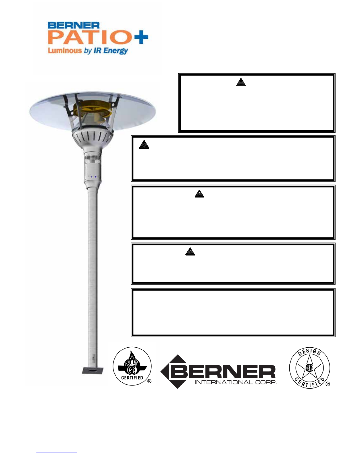
A PATIO HEATER
LIKE NO OTHER
PARASOL
Radiant Patio Heater
Manual for Installation, Operation & Maintenance
DANGER
If you smell gas:
1. Shut off gas to appliance.
2. Extinguish any open flame.
3. If odor continues, immediately call your
WARNING: Improper installation, adjustment, alteration,
service or maintenance can cause injury or property damage.
Read the installation, operating and maintenance instructions
thoroughly before installing or servicing this equipment.
FOR YOUR SAFETY
Do not store or use gasoline or other flammable vapors and
liquids in the vicinity of this or any other appliance. A propane
cylinder not connected for use shall not be stored in the vicinity
of this or any appliance.
The Even-GLO Patio heater has been approved for indoor use in non-residential
*
applications (See page 8 for details) for natural gas units ONLY
IMPORTANT: The installer must leave these instructions with
the owner. Only those who are certified to do so should
* FOR OUTDOOR USE ONLY
™
111 Progress Ave.
New Castle, PA 16101
www.berner.com
March, 2013
Page 2

BERNER PATIO+ Parasol
Page 2
March, 2013
Page 3

Table of Contents
1 - CAUTION AND GENERAL SAFETY ...................................................................... 4
2 - PRE-INSTALLATION OVERVIEW ........................................................................ 5
WHAT YOU WILL RECEIVE ............................................................................................................ 5
MOUNTING PLATE HOLE PATTERN .................................................................................................. 6
WHAT YOU NEED TO SUPPLY ......................................................................................................... 7
3 - LOCATION PLANNING ...................................................................................... 8
GENERAL LOCATION LAYOUTS ........................................................................................................ 8
LOCATION REQUIREMENTS ............................................................................................................ 8
4 - CLEARANCE TO COMBUSTIBLE MATERIALS ...................................................... 9
CLEARANCE TO COMBUSTIBLES ...................................................................................................... 9
INSTALLATION / CODE REQUIREMENTS ............................................................................................ 9
5 - INSTALLATION INSTRUCTIONS ....................................................................... 10
EQUIPMENT DIMENSIONS ........................................................................................................... 10
5 - INSTALLATION INSTRUCTIONS ....................................................................... 11
POWER / GAS SPECIFICATION ...................................................................................................... 12
6 - ASSEMBLY ...................................................................................................... 13
FLOOR MOUNT ......................................................................................................................... 13
CEILING MOUNT ....................................................................................................................... 19
7 - WIRING .......................................................................................................... 26
WIRING DIAGRAMS ................................................................................................................... 27
INTERNAL WIRING ..................................................................................................................... 27
EXTERNAL WIRING OPTIONS........................................................................................................ 28
8 - LIGHTING & SHUTDOWN INSTRUCTIONS ....................................................... 29
LIGHTING ................................................................................................................................. 29
SHUT DOWN ............................................................................................................................ 29
9 - MAINTENANCE AND TROUBLE SHOOTING ..................................................... 30
MAINTENANCE ......................................................................................................................... 30
TROUBLE SHOOTING .................................................................................................................. 30
10 - PARTS LIST ................................................................................................... 31
12 - WARRANTY .................................................................................................. 33
BERNER PATIO+ Parasol
Page 3
March, 2013
Page 4

1 - Caution and General Safety
CAUTION: FIRE OR BURN INJURY HAZARD
• At all times maintain clearance to combustible materials as further specified in this
manual. Failure to do so can result in serious fire hazard.
• Never operate heaters in atmosphere containing flammable vapours or combustible
dusts.
• This heater is equipped with an electronic and automatic ignition device. Do not attempt
to light the burner by hand. Failure to comply can result in a serious fire and personal
injury hazard.
• Certain materials, when stored under this heater are subjected to radiant heat can soften,
distort or otherwise be damaged, special care should be taken of plastic materials
• Appliance surfaces, other than the obvious flame and emitter surfaces, attain elevated
temperatures during operation. Do not touch the heater head during operation. Everyone
should be alerted to this hazard to avoid burning.
• Children should be strictly supervised when in the area of this heating appliance. Playing
or running around the structure should be strictly forbidden.
• Clothing or other flammable materials should not be hung on or near this heater.
BERNER PATIO+ Parasol
Page 4
March, 2013
Page 5
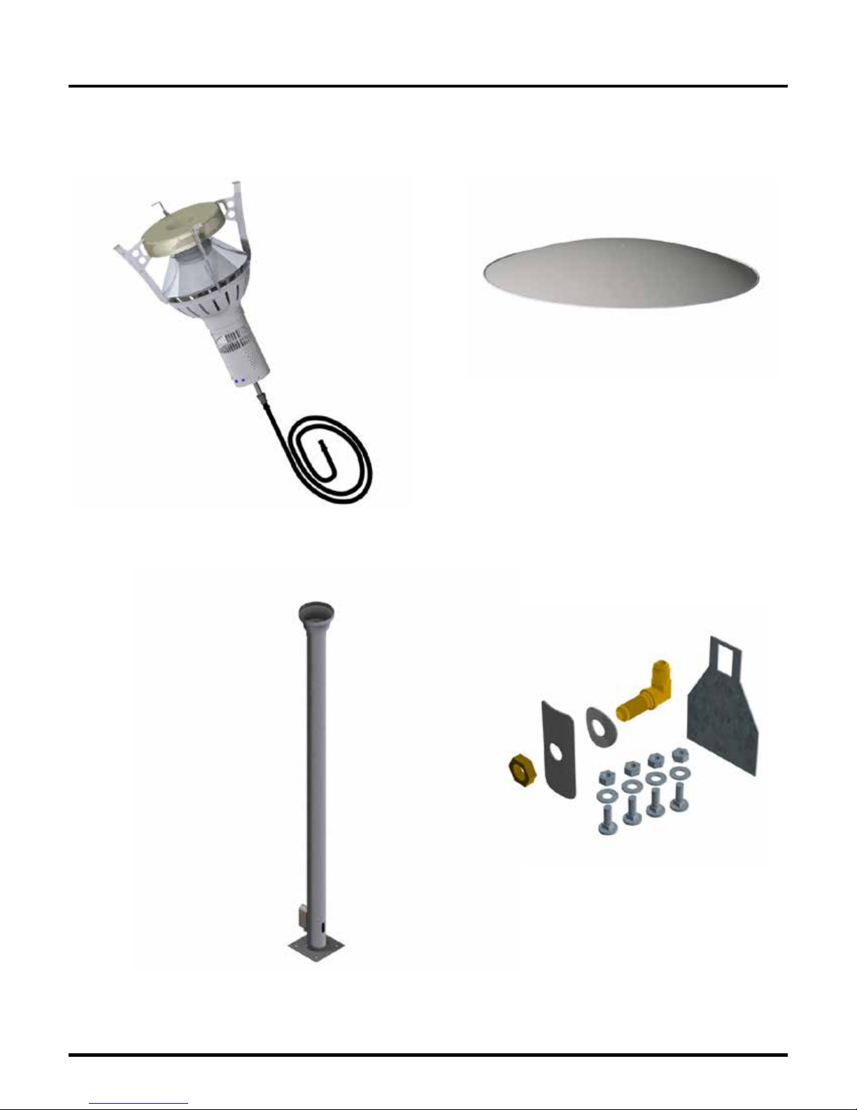
What You Will Receive
Top Reflector
Heater head Assembly
Pole Assembly
Hardware
2 - Pre-installation Overview
BERNER PATIO+ Parasol
Page 5
March, 2013
Page 6
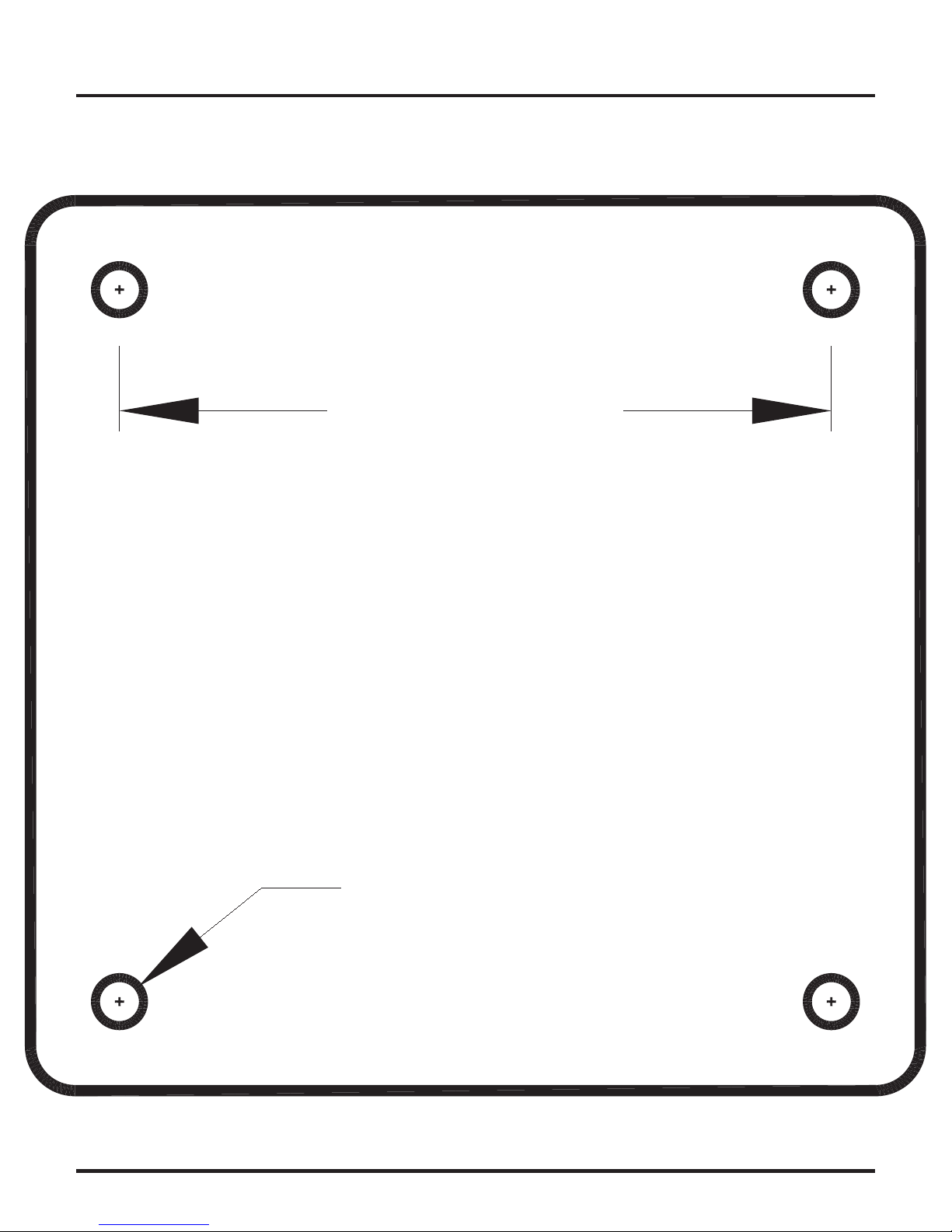
2 - Pre-installation Overview
Mounting Plate hole Pattern
(Full size)
6.30"
BERNER PATIO+ Parasol
Ø0.42"
Page 6
March, 2013
Page 7

What You Need to Supply
1. Heater post anchoring hardware.
2. Materials necessary to construct a concrete base for floor mounting.
3. Gas supply line that is installed to the Gas and Electric Supply according to the:
National Fuel Gas Code, ANSI Z.223.1 (NFPA 54) in the US and Natural Gas and
Propane Installation Code, CSA B149.1 or Propane Storage and Handling Code,
B149.2 in Canada.
4. Electrical supply rated at 24 Vac with two stage control.
2 - Pre-installation Overview
BERNER PATIO+ Parasol
Page 7
March, 2013
Page 8
3 - Location Planning
NOTE: Sprinkler head heat fuse link performance may alter with age.
WARNING!
General Location Layouts
One Parasol heater, at high fire and in windless conditions, has a comfort radius of
about twelve feet (24 ft. circle).
A series of heaters providing area heat should be placed about 14-20 feet apart.
Wind protection has an important influence on the body’s ability to retain radiant heat. Use
natural or newly built wind barriers where possible, such as existing buildings, shrubbery or tree
lines and
fences
This heater is NOT approved for any indoor Residential
application. If in doubt of your application consult with your
local fire marshal or gas authority having jurisdiction. Indoor
spaces include but are not limited to attached garages,
solariums, living quarters etc.
A patio that has been almost entirely closed in with a roof and windbreak walls or a tent
may be considered an indoor location by some code authorities. The Lynx Patio heater
has been approved for indoor use in non residential applications (Natural Gas Models
ONLY). Venting of the flue gases is accomplished by means of an interlocked fan. Refer
to the National Fuel Gas Code, ANSI Z.223.1 (NFPA 54) in the US and CAN/CGA B149.1
and B149.2 Installation Codes in Canada.
Location Requirements
a. Never locate the heater directly below electrical lines, gas lines or sprinkler systems.
b. Do not locate heater too close to vinyl or plastic wall coverings. These materials may
discolour or soften well before they reach combustible limits.
c. Always allow room for re
purposes.
d. The heater aspirates air for combustion. Do not locate heater where there are severe
draft conditions or airflow restrictions to the heater head base.
moval of the top reflector and heater head for maintenance
BERNER PATIO+ Parasol
Page 8
March, 2013
Page 9
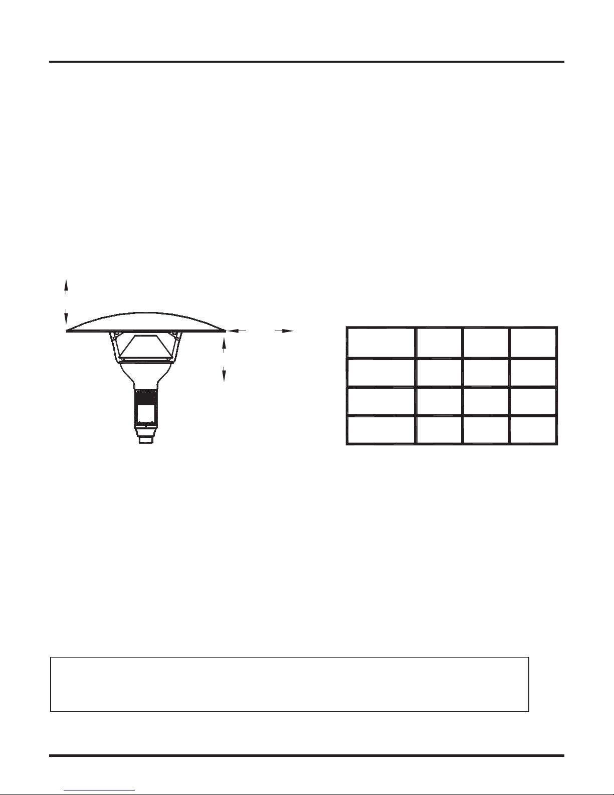
4 - Clearance to Combustible Materials
CLEARANCE TO COMBUSTIBLES
Clearance to Combustibles
The following clearance data is based on a maximum limit of 90°F (50 °C) plus ambient
temperature.
Note with an ambient temperature of 70°F the surface temperatures at the clearance
distances listed below could reach 160°F Care should be taken with placement of plastic
or vinyl in the proximity of the heater as they tend to distort and soften at these
temperatures.
The
INSTALLER is responsible to ensure that building materials with a low heat tolerance
which may degrade at higher temperatures are protected to prevent degradation.
TOP
SIDE
MODEL NO. TOP SIDES BELOW
BELOW
BPP-E301NU
BPP-E301PU
22"
33"18"
BPP-E301NT
BPP-E301PT
BPT-E301NH
BPT-E301PH
22"
22"
33"18"
33"18"
Installation / Code Requirements
Installation must comply with local building codes and/or, for the USA/National Fuel Gas Code,
ANZI Z 223.1 (NFPA 54) and for Canada, CAN/CGA B149.1 and B149.2, National Gas and
Propane Installation Code (latest editions).
Appliance must be electricall
National Electrical Code, ANSI/NFPA 70 in the USA, CSA C22.1 Canadian Electrical Code in
Canada.
NOTE: Some materials deteriorate or soften at sustained temperatures below 160°F.
Consult material manufacturer for recommendations
y grounded in accordance with local codes or, in their absence; the
BERNER PATIO+ Parasol
Page 9
March, 2013
Page 10
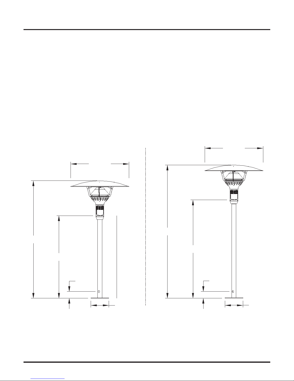
5 - Installation Instructions
8"
8"
Installation must comply with local building codes and/or, for the USA/National Fuel Gas Code,
ANZI Z 223.1 (NFPA 54) and for Canada, CAN/CGA B149.1 and B149.2, National Gas and
Propane Installation Code (latest editions).
Appliance must be electrically grounded in accordance with local codes or, in their absence; the
National Electrical Code, ANSI/NFPA 70 in the USA, CSA C22.1 Canadian Electrical Code in
da.
Cana
Equipment Dimensions
Floor mount models
89.7"
Model BPP-E301NUB
Model BPP-E301PUB
39.5"
63.0"
Model BPP-E301NTB
Model BPP-E301PTB
39.5"
101.7"
75.0"
5.1"
BERNER PATIO+ Parasol
Page 10
5.1"
March, 2013
Page 11

17.95"
5 - Installation Instructions
Hanging TEAR-DROP
Model BPT-E301 / NHB BPT-EPHB
1.13"
Ø39.50"
47.98"
46.81"
BERNER PATIO+ Parasol
6 Feet Minimum Clearance Below
Page 11
March, 2013
Page 12

5 - Installation Instructions
Low fire rate: Natural - 46,000 btuh Propane - 40,000 btuh
Natural Gas: Minimum 6.5 ” W.C. Maximum 14.0 ” W.C.
Propane Gas: Low - 7.0” W.C. High - 9.8” W.C.
Power / Gas Specification
High fire rate: Natural - 53,000 btuh Propane - 47,000 btuh
Gas Supply Pressure:
Propane Gas: Minimum 10.8 ” W.C. Maximum 14.0 ” W.C.
Manifold Pressure:
Natural Gas: Low - 4.0” W.C. High - 5.5” W.C.
Electric Supply: 24 VAC, 0.8A
Installation or repair should only be done by personnel qualified for
the installation of powered gas appliances.
The appliance and its individual shutoff valve must be disconnected from the gas supply piping
system during any pressure testing of that system at test pressures in excess of ½ psig (3.5
KPa)
BERNER PATIO+ Parasol
Page 12
March, 2013
Page 13

6 - Assembly
Floor Mount
a. Mount pole base onto a concrete floor or cast concrete with a minimum below grade
depth of 12” and having a 12” diameter. If forming concrete, cast in place appropriate
passage for gas and control wires. Use minimum 3/8” x 5” 90° lag bolts or equivalent to
mount heater base to the concrete base. The pole base could also be mounted on wood
decks with 3/8” bolts and lock washers on the underside of the deck. Periodically check
for tightness when mounted to a wood deck.
BERNER PATIO+ Parasol
Page 13
March, 2013
Page 14

6 - Assembly
b. Arrange the burner head such that the wires and gas hose are arranged as illustrated. Feed
a pull wire through the pole to assist in pulling the three power wires into the pole and
through the junction box. Firmly tape the pull wire to the power wires. Lower the assembly
into place while pulling the wires. Two people may be necessary for this operation.
BERNER PATIO+ Parasol
Page 14
March, 2013
Page 15

c. Secure burner head to pole with three #10 screws provided.
6 - Assembly
BERNER PATIO+ Parasol
Page 15
March, 2013
Page 16

6 - Assembly
d. Push the gas connection into the slot buy slightly pushing on the gas line through the
electrical box. The gas fitting should be positioned as illustrated below.
BERNER PATIO+ Parasol
Page 16
March, 2013
Page 17

6 - Assembly
e. Place gas connection cover onto the fitting and install the nut to fasten the cover
assuring the nut is properly seated. See below.
BERNER PATIO+ Parasol
Page 17
March, 2013
Page 18

6 - Assembly
f. Install reflector using the four carriage bolts, nuts and washer provided.
g. Connect gas supply and electric power following all local codes. Pressure test all gas
connections.
BERNER PATIO+ Parasol
Page 18
March, 2013
Page 19

Ceiling Mount
1. Assemble 4 gusset plates to the base as illustrated. Use 5/16” carriage bolts with
washers and nuts.
6 - Assembly
BERNER PATIO+ Parasol
Page 19
March, 2013
Page 20

6 - Assembly
2. Assemble angular arms to the base.
3. Assemble vertical arm to angular arm using two gusset plates and 5/16” carriage bolts
with nuts and washers. Repeat this for the other side.
BERNER PATIO+ Parasol
Page 20
March, 2013
Page 21

4. Install mounting brackets on both sides with supplies hardware.
6 - Assembly
5. Mount the heater base assembly to the ceiling in the desired location keeping in mind
clearance to combustibles. Use minimum 6 #14 x1.5” wood screws.
Caution: To prevent possible head injury provide pedestrian protection if lowest
point of the heater is less than 7 feet in height. The heater must have a minimum
clearance of 6 Feet below.
BERNER PATIO+ Parasol
Page 21
March, 2013
Page 22

6 - Assembly
6. Install heater assembly into the base assembly allowing the gas line and wires through
the bottom. Use three #8-32 type F to secure heater head to the base.
BERNER PATIO+ Parasol
Page 22
March, 2013
Page 23

7. Feed the gas line and control wires through either side of the assembly.
6 - Assembly
BERNER PATIO+ Parasol
Page 23
March, 2013
Page 24

6 - Assembly
8. Install the heat shields as illustrated using the #8-32 type F screws supplied.
9. Install the bottom cover to complete the assemble using 4 #8-32 type F screws.
BERNER PATIO+ Parasol
Page 24
March, 2013
Page 25

10.Installation of reflector support brackets.
1. After putting on heat shields, screw reflector
brackets to frame upright.
2. Secure reflector by screwing the reflector to
the reflector support brackets.
6 - Assembly
1
x 2
2
BERNER PATIO+ Parasol
Page 25
March, 2013
Page 26

7 - Wiring
This appliance requires a 24 volt AC supply with a minimum 20 VA capacity. Below is a
suggested control circuit for operating this appliance. The switching mechanisms may also be
Timers
The supply cord shall be kept away from heated surfaces.
Blue
Hi
Lo
To Patio Heater
Red
On
Off
24V
20VA
Min
Green
24
120V
Ensure a good
ground source
BERNER PATIO+ Parasol
Page 26
March, 2013
Page 27

Wiring Diagrams
HI
LO
C
IH
Internal Wiring
7 - Wiring
Red
Green
Green
Yellow
Green
Pink
Green
Spark Electrode
If any of the original wire as supplied with the
appliance must be replaced, it must be replaced
with wiring material having a temperature rating
of at least 105°C.
Red
24 VAC (Lo)
Green
Gas Valve
Yellow
Blue
LEDs
Blue 24 VAC (Hi)
Si l'un des fils électriques original fournis avec
cet appareil doit etre remplacé, le remplace avec
un fil électrique fait de la température évaluation
d'au moins 105°C.
EL013
01/08
BERNER PATIO+ Parasol
Page 27
March, 2013
Page 28

7 - Wiring
External Wiring Options
Option 1:
Using 2 Toggle Switches
115 VAC
Grounded
Supply
24 Volt
Transformer
Patio
Heater
24 Volt
AC
Supply
On
Off
**Ensure A Good
Ground Source
Hi (on)
Low (On)
Blue
Red
Green
To
Patio
Heater
Option 2:
Using 2-Stage Switch
(SRP P/N EE020)
24 VAC
24 Volt AC Supply
Grounded Neutral
N
Back Box
X
1
NC 1 NO 3
X
2
4
2
Blue
Red
Green
Front Cover
(Hi)
(Low)
To Patio
Heater
BERNER PATIO+ Parasol
Page 28
March, 2013
Page 29

8 - Lighting & Shutdown Instructions
Lighting
1. Open manual gas supply valve (ensure gas supply lines have been purged).
2. Turn on switch to energize electric supply.
3. The electronic control module will time begin the ignition period in 3 seconds.
4. The gas valve will open and ignition spark will commence and continue for 20 sec.
5. If flame starts and “is detected”, flame will continue until turned off.
6. If no flame is detected, the gas valve will close after 20 sec. A “wait’ period commences
and lasts approximately 5 sec. and a second trial for combustion commences. The
electronic control will attempt three trials for ignition before locking out for approximately
5 minutes at which time it will automatically try again.
Electronic control of heater can be re-set by de-energizing and re-energizing electric power.
Shut Down
1. Turn off power to electronic control.
2. For longer periods of shut down, also close manual gas supply valve.
BERNER PATIO+ Parasol
Page 29
rch, 2013
Ma
Page 30

9 - Maintenance and Trouble Shooting
Maintenance
• Before performing any service shut off gas and electric supply.
• Check condition of burner, especially integrity of flame screen.
• Inspect condition of spark and sense electrode. Check for cracks in ceramic insulators or
excessive corrosion.
• Inspect condition of high tension lead to spark rod.
• Annually verify hose gas supply in heater post and all connections for gas leaks.
Trouble Shooting
No Gas Supply at Burner
• Ensure manual shut off valve is in proper position
• Ensure there is pressure and flow at inlet to gas valve.
• Ensure gas valve gets 24v power from control module during ON cycle.
No Spark
• Ensure control module has 24VAC supply
• Ensure spark electrode assembly is grounded and there are no cracks in ceramic
insulator.
Flame Lights but Will Not Stay Lit
• Ensure there is no overpowering wind.
• Ensure sense electrode is not corroded, is not grounded or has a cracked insulator.
E
lectrode position is radially across face of burner.
BERNER PATIO+ Parasol
Page 30
March, 2013
Page 31

10 - Parts List
Item
Description
Part #
A
Reflector package
ES041
Gas Hose Assembly 63”
Gas Hose Assembly 75”
EG014
EG027
C
Emitter
ES011
D
Flame Sensor
EE002
E
Spark Electrode
EE001
F
Electronic Control Module
EE009
Item
Description
Part #
I
Indicator Light (not shown)
EE010
J
Burner assembly
EG008
Pole Package Black 63”
Pole Package S/S 75”
ES114
ES132
M
Ignition wire (not shown)
EE005
Orifice (NAT)
G
Orifice (LPG)
B
Gas Valve (NAT)
H
Gas Valve (LPG)
Pole Package Black 75”
K
Pole Package S/S 63”
EG002
EG022
EG001
EG023
ES131
ES081
BERNER PATIO+ Parasol
Page 31
March, 2013
Page 32

10 - Parts List
Item
Description
Part #
C
Emitter
ES011
D
Flame Sensor
EE002
E
Spark Electrode
EE001
F
Electronic Control Module
EE009
Gas Valve - NAT Gas
Gas Valve - LP Gas
EG001
EG023
I
Indicator Light
EE004
J
Burner assembly
EG008
TEAR-DROP MODEL
A Reflector package ES041
B Gas Hose Assembly EG004
Orifice - NAT Gas
G
Orifice - LP Gas
H
M Ignition wire (not shown) EE005
EG002
EG022
BERNER PATIO+ Parasol
Page 32
March, 2013
Page 33

12 - Warranty
BERNER PATIO+ PARASOL
PORTABLE, FIXED AND TEAR-DROP BPP-E201, BPP-E301 & BPT-E301
WARRANTY
The Manufacturer warrants to the original owner that the product will be free of defects
in material and workmanship for a period of 5 years from the date of purchase, for
everything except the electronic control module, spark electrode, and sense electrodes
which have a replacement warranty period of 3 years.
The Manufacturer’s obligation under this warranty is limited to repair or replacement;
FOB its facility, of the defective part. In the case of replacement pa
period shall be the longer of the original warranty or a period of 12 months from the
date of purchase. In no event shall the Manufacturer be liable for incidental expense or
consequential damages of any kind.
rts the warranty
This warranty does not cover any shipping, installation or other costs incurred in the
repair or replacement of the product. No materials will be accepted for return without
authorization.
This warranty will not apply if, in the judgement
been improperly installed, unreasonably used, damaged or modified.
This warranty will not apply to damage to the product when used in corrosive
atmospheres. No person is authorised to assume for the Manufacturer any other
warranty, obligation or liability.
THE REMEDIES PROVIDED FOR IN THE ABOVE EXPRESS WARRANTIES ARE
THE SOLE AND EXCLUSIVE REMEDIES. NO OTHER EXPRESS OR IMPLIED
WARRANTIES ARE MADE INCLUDING, BUT NOT LIMITED TO,
WARRANTY OF MERCHANTABILITY OR FITNESS FOR A PARTICULAR USE OR
PURPOSE.
of the Manufacturer, the equipment has
ANY IMPLIED
BERNER PATIO+ Parasol
Page 33
March, 2013
 Loading...