

Page 1
No. II-300
Date: August, 2011
READ AND SAVE THESE INSTRUCTIONS
Installation & Maintenance Instructions
For the In-Ceiling Mount Air Curtain with Intelliswitch®
TABLE OF CONTENTS
IN-CEILING MOUNT AIR CURTAIN
I. UNCRATING.................................................................................................................................................................. 2
II. MOUNTING PREPARATION.................... ................................................................................................................... 2
III. MOUNTING ................................................................................................................................................................ 3
IV. ELECTRICAL CONNECTIONS .................................................................................................................................... 3
V. FIELD CONNECTIONS ................................................................................................................................................ 4
VI. AIRFLOW ADJUSTMENTS ........................................................................................................................................ 4
VII. MAINTENANCE AND CLEANING ............................................................................................................................ 4
VIII. SERVICE ..................................................................................................................................................................... 5
TROUBLESHOOTING......................................................................................................................................................19
INTELLISWITCH®
QUICK START PROGRAMMING................................................................................................................................... 8-9
FAQ’s (FREQUENTLY ASHED QUESTIONS)............................................................................................................ 10-11
INTELLISWITCH® DETAILED PROGRAMMING...................................................................................................... 12-18
WARNING: TO REDUCE THE RISK OF FIRE, ELECTRIC SHOCK OR INJURY TO PERSONS, OBSERVE THE FOLLOWING:
A. Use this unit only in the manner intended by the manufacturer. If you have any questions, contact the manufacturer.
B. Before servicing or cleaning unit, switch power o at service panel and lock the service disconnecting means to prevent power from being
switched on accidentally. When the service disconnecting means cannot be locked, securely fasten a prominent warning device, such as a
tag, to the service panel.
C. Installation work and electrical wiring must be done by qualied person(s) in accordance with all applicable codes and standards, including
re-rated construction. (See page 4 V. ELECTRICAL CONNECTIONS (NEC Code ANSI/NFPA No. 70)
D. Sucient air is needed for proper combustion and exhausting of gases through the ue (chimney) of fuel burning equipment to prevent
back drafting. Follow the heating equipment manufacturer’s guideline and safety standards such as those published by the National Fire
Protection Association (NFPA), and the American Society for Heating, Refrigeration and Air Conditioning Engineers (ASHRAE), and local
code authorities.
E. When cutting or drilling into wall or ceiling, do not damage electrical wiring and other hidden utilities.
www.intelli-how2.com 800-245-4455 www.berner.com
Page 2
I. UNCRATING
Carefully examine the carton(s) for damage. If the carton
is damaged, immediately notify the shipping company. Do
not delay in ling claim. If the air door(s) were shipped on
wooden skids, remove protective wood and banding straps securing the carton(s) to the skid. Open the carton(s) and remove
all protective packaging. Immediately verify that the electrical
rating nameplate located on the cover matches electrical power
supply available. Retain the shipping carton(s) until the air
door(s) are installed and properly operating.
ACCESSORIES: If the air door(s) were ordered with optional
electrical accessories, the accessories will be found in the carton
containing the air door or in a separate carton(s) accompanying the air door(s). Check all of the cartons/skids for accessories
before discarding.
II. MOUNTING PREPARATION
INDOOR MOUNTING ONLY - Environmental/Insect/Dust Control
A. The In-Ceiling Mount air curtain is designed to be an ef-
fective barrier against cold drafts in the winter and hot air
in the summer. To achieve optimum protection, the unit
should be mounted on the inside of the building, ush with
the ceiling, so that the airstream can pass as close to the
top of the door opening as possible. To ensure peak performance keep the air stream free of obstructions.
B. The air door will not perform properly if negative air
pressure exists in the building. Under these conditions,
a means for makeup air to the building must be provided so that the air pressure on both sides of the opening
is in balance.
C. Before mounting the air door, check the supporting struc-
ture to verify that it has sucient load-carrying capacity to
support the weight of the unit(s). The mounting hardware
(supplied by others) should be capable of supporting a
minimum of three (3) times the weight of the unit. See
Table 1.
D. When determining the mounting location for the unit(s),
make sure that nothing interferes with the curtain of air
Model
ICA/FCA1036A 100 104 115
ICA/FCA1042A 107 111 124
ICA/FCA1048A 113 11 7 133
ICA/FCA1060A 133 137 160
ICA/FCA2060A 170 178 197
ICA/FCA2072A 177 185 205
ICA/FCA2084A 202 210 237
ICA/FCA2096A 215 223 256
ICA/FCA3096A 252 264 293
ICA/FCA2108A 222 230 267
ICA/FCA3108A 259 271 304
ICA/FCA3120A 269 281 318
ICA/FCA3132A 291 303 346
ICA/FCA3144A 304 316 364
ICA/FCA4144A 341 357 401
Total Net
Weight Ambient
Total Net
Weight - Electric
Heat
Total Net
Weight - Steam/
Hot Water Heat
Table 1
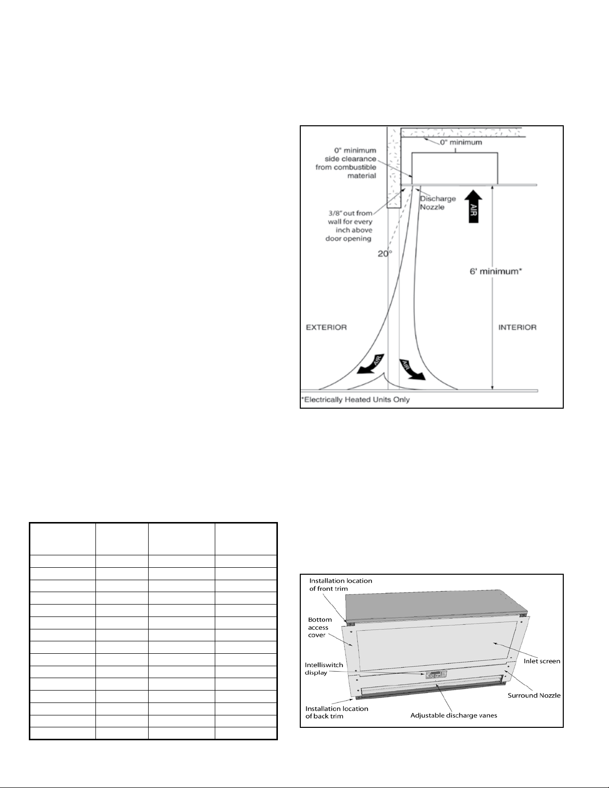
developed when the discharge vanes are directed from 0°
to 20° toward the door opening. If the air stream strikes any
obstruction (the top edge of the doorway, a door opening
device, etc.), the eectiveness of the unit will be greatly
reduced. See Figure 1.
E. For optimum performance, the bottom of the discharge
nozzle should be located in such a manner that it is spaced
Figure 1
out from the wall 3/8” for every inch the unit is above the
door opening.
F. Electric heated unit(s) shall:
Have a minimum clearance of at least 6’ between the 1.
bottom of the unit and the oor.
Be installed Indoors Only.2.
The unit is shipped without the front and back trim 3.
installed to protect it from shipping damage. This trim
need not be installed until after the unit is hung. See
Figure 2.
Figure 2
2
Page 3
III. MOUNTING
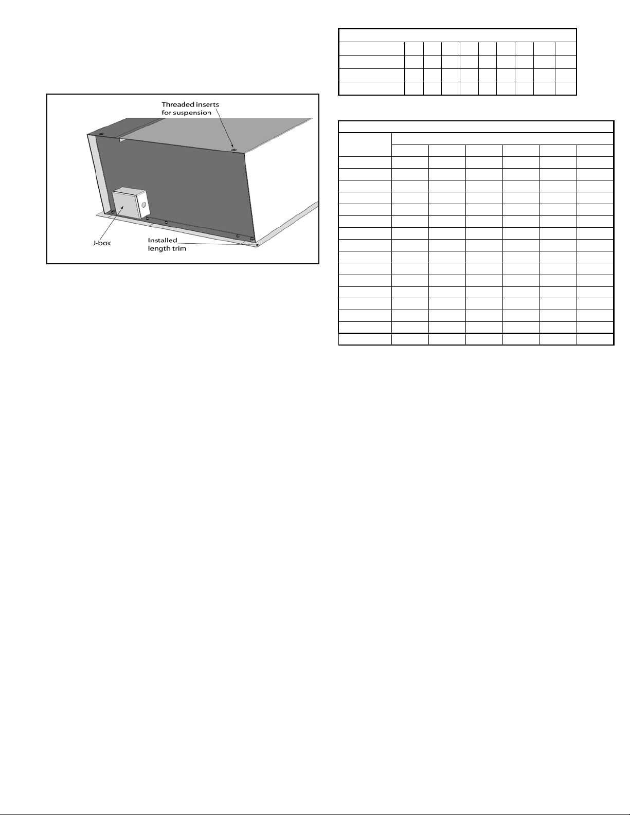
A. The ICA/FCA series air door enclosure is equipped with four
5/16”-18 threaded inserts on the top of the unit for suspended mounting. See Figure 3.
Figure 3
For lighter lifting the blower assembly may be removed
so that the enclosure can be easily installed. See
Section VIII: SERVICE for instruction on removing the
blower assembly.
B. The electrical junction box is located on the outside of the
enclosure on the left side of the unit.
C. Determine the exact mounting location of the air door unit.
D. Create structural attachment points to suspend the unit
above the ceiling so that the unit is centered and parallel
with the door opening.
E. Suspend air door cabinet by attaching threaded rods to
the unit and support structures. Adjust unit position so
the bottom of the cabinet is ush with the underside of the
ceiling.
F. Install the front and back trim using the provided fasteners.
See Figure 3.
G. Finish o ceiling edge as required.
NOTE: Finishing materials must not overlap the bottom of
the cabinet to allow the intake screen to open freely.
H. If the blower assembly was removed, re-install it along with
nozzle surround and bottom access cover.
IV. ELECTRICAL CONNECTIONS
All electrical wiring and connections MUST be performed by
qualied personnel in accordance with the latest edition of the
National Electrical Code ANSI/NFPA No. 70 or, in Canada, the
Canadian Electrical Code, Part 1-C.S.A. Standard C22.1 and local
codes and regulations.
A. Check the rating nameplate on the unit for supply voltage
and current requirements. A separate line voltage supply
with a suitable branch circuit protection device should be
run directly from the main electrical panel to the unit. A
disconnect switch for each branch circuit is a required part
of this installation. See Table 2 & 3 for component electri-
cal loads. See the voltage label on the unit for circuiting
and total electrical load.
Motor Voltages/Amp Draws
Volts 120 208 240 208 240 480 600 220 380
Phase 1 1 1 3 3 3 3 1 1
Hertz 60 60 60 60 60 60 60 50 50
Amps per Motor 6.5 3.5 3.5 3.5 3.5 1.4 1
3.5 3.5
Table 2
Heater Amp Draws for Selected kW
Heater kW
6 kW 28.9 25.1 16.7 14.5 7.2 6.0
8 kW 38.5 33.5 22.2 19.3 9.6 8.0
10 kW 48.1 41.9 27.8 24.1 12.0 10.0
12 kW 57.7 50.3 33.4 28.9 14.4 12.0
14 kW 67.3 58.7 38.9 33.7 16.8 14.0
16 kW 77.0 67.0 44.5 38.6 19.2 16.0
18 kW N/A N/A 50.0 43.4 21.6 18.0
20 kW N/A N/A 55.6 48.2 24.0 20.0
24 kW N/A N/A 66.7 57.8 28.8 24.0
28 kW N/A N/A 77.8 67.5 33.6 28.0
30 kW N/A N/A 83.4 72.3 36.0 30.0
32 kW N/A N/A 88.9 77.1 38.4 32.0
40 kW N/A N/A 111.2 96.4 48.0 40.0
42 kW N/A N/A 116.8 101.2 50.4 42.0
56 kW N/A N/A 155.7 135.0 67.2 56.0
Amps per kW 4.81 4.19 2.78 2.41 1.20 1.00
208/1 240/1 208/3 240/3 480/3 600/3
Heater kW Amp Draws
Table 3
B. All eld wiring must be copper with a minimum insulation
of 60°C within approved conduit. If any of the wire supplied
with the unit must be replaced, it must be replaced with
copper wiring with a minimum insulation of 90°C.
C. Electric, steam and hot water heated air doors are factory
equipped with an air curtain mounted solid state temperature sensor cable (for Intelliswitch® thermostat) located
on the outside of the left endplate. Depending on where
the temperature is to be measured, the sensor may be left
on the endplate or positioned elsewhere. Do not put any
clamps on the rubber coated tip.
D. Remove the junction box cover.
E. Connect all supply and control circuit wires according to
the wiring diagram provided.
NOTE: For Electric heated air doors provided with the op
tional remote thermostat, mount and wire the thermostat
according to instructions and wiring diagram.
F. Master/Slave connection, if two or more air doors are to
be linked together for Master/Slave operation, continue,
otherwise, skip to Step G.
NOTE: The air door must have been ordered from the
factory with this option.
NOTE: One Intelliswitch® serial cable assembly (part #
505SC***INT485-A) is required for every air door that is to
be used as a Master/Slave. “***” denotes length of cable in
feet “008”= 8 ft. long.
3
Page 4
For Master/Slave operation, a serial cable connection must be
made between the Intelliswitch® control boards of each air door
to be linked.
1. Disconnect power to all the air doors
2. Find the (RS485) phone jack couplers protruding through
the hole in the endplate next to the j-box.
3. The serial cable ordered for each air door will be coiled up
and attached to the left endplate.
NOTE: There will be one less serial cable than the number of
air doors ordered. E.g. Two air doors together will need only
one cable; three air doors together will need two cables,
etc. Any extra cables can be kept as spares.
V. FIELD CONNECTIONS
A. ELECTRICALLY HEATED MODELS
The heater circuit may be controlled by a remote thermo-
stat or manually through the Intelliswitch® located on the
discharge side of the air door. Overheating protection is
provided by auto reset thermal cutouts built into the heater
coil assembly (see the wiring diagram).
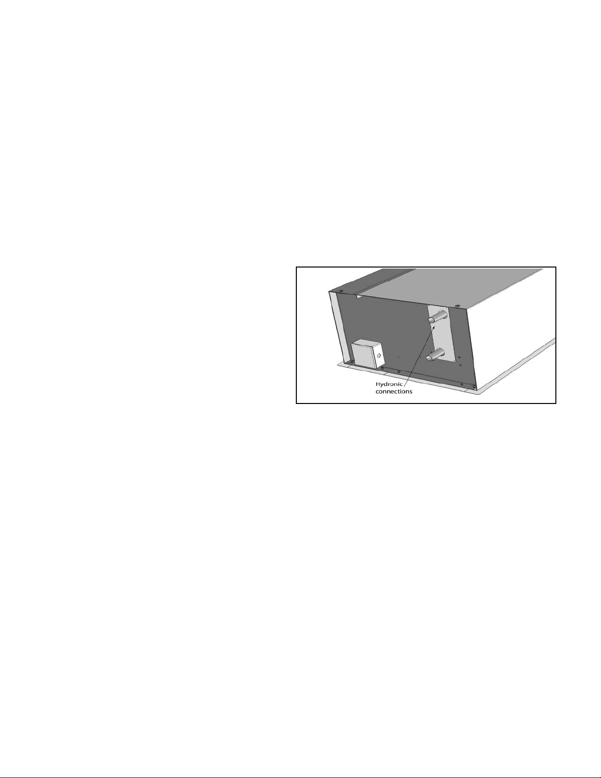
B. STEAM AND HOT WATER HEATED MODELS
Piping should be done in accordance with local codes,
regulations and standard practices. Connect the building
system supply and return to the ¾” MPT nipples on the
heating coil. See Figure 4.
4. Plug the (RS485) male phone jack on the end of the serial
cable into the empty coupler on the next air door.
5. Continue process for all air doors that are to be connected
serially.
6. Serial cable connections are capable of two way communication. It does not matter to which coupler the cables are
connected.
7. The rst and last air door in the group will each have an
empty coupler after all connections are made. If there are
only two air doors connected, each will have an empty
cable coupler.
NOTE: If a longer cable is required than was supplied, it can
be ordered from the factory or made by using standard 4
wire at telephone cable, phone jack connectors and the
proper crimping tool.
G. Remote Mounted Display Faceplate – If operation of the
Intelliswitch® is to be through a Factory Ordered Remote
Mounted Display Faceplate, continue, otherwise, skip to
step H.
NOTE: Maximum mounting distance between the Display
Faceplate and the air door is 20’.
1. When the remote faceplate option is ordered from the
factory, the air door comes equipped with the blank
faceplate already installed and the 20’ ribbon cable attached. The Display Faceplate is shipped loose, ready
for eld installation.
2. Locate the male end of the conductor ribbon cable
and run it to the remote display location. The cable
is minimum CL2 rated and should not need to be in
conduit.
3. Connect the female end of the ribbon cable to the
14-pin socket on the back of the display board with
the cable approaching from the top and the red ribbon
indicator to the right (when facing the front of the
display board).
4. Mount Display Faceplate to the wall.
H. For Electric, Steam and Hot Water air doors proceed to
Section V - Field Connections otherwise proceed to
Section VI - Airow Adjustments
VI. AIRFLOW ADJUSTMENTS
A. With the air door operating and the door in its full open
position, check to see that nothing is obstructing the air
ow at the discharge nozzle vanes.
Figure 4
B. Find the air stream split location. Hold a handkerchief, by
its corners, approximately 12” above the oor. Gently move
the handkerchief back and forth in the doorway. Make sure
the air is being directed to both the inside and the outside.
The split location is indicated where the handkerchief is
vertical with minimal or no uttering. See Figure 5.
C. Adjust the discharge nozzle vanes so the split location is
approximately 3” outside the doorway. Loosen the nozzle
vane locking screws and adjusting the vanes.
VII. MAINTENANCE AND CLEANING
CAUTION: ELECTRIC SHOCK HAZARD Disconnect power
when ever servicing unit. More than one disconnect may be
required to de-energize unit.
Keep your air door operating at peak eciency by cleaning the
blower wheels, motor(s) and intake grille. Buildup of dust on
the blower wheels can cause vibration, noise and excessive
wear on the motor bearings. The frequency of cleaning will
depend on the environment where the unit is operating.
Dirty, dusty or greasy environments could require a cleaning
schedule of once every two months. Otherwise, the unit(s)
should be scheduled for cleaning a minimum of once every (6)
months. To access the interior of the unit:
4
Page 5
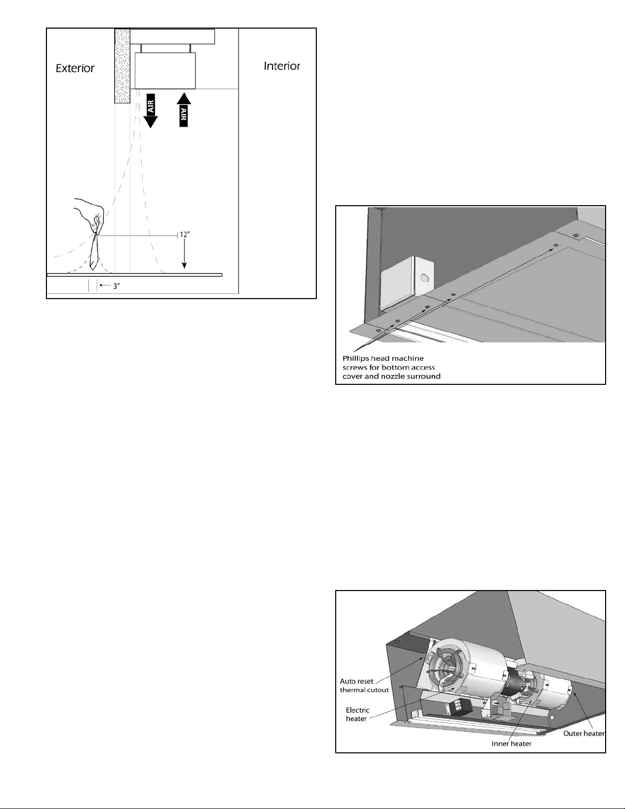
Figure 5
sealed, sleeve bearings and require no maintenance.
A. To remove the blower module and clean or replace the fans
and motor:
1. Disconnect and lockout power to the unit.
2. Remove the bottom access cover by removing (4) Phillips head machine screws located at the cover’s corners.
See Figure 6.
3. If desired, the nozzle surround may be removed to
provide more working room. To remove the nozzle surround, remove the (4) Phillips head machine screws from
the corners. The Intelliswitch® ribbon cable must also be
disconnected from the back of the display circuit board
A. Disconnect and lockout power to the unit. If necessary
remove the blower assembly. See Section VIII: Service for
instructions on how to remove blower module.
B. Remove the bottom access cover by removing (4) Phillips
head machine screws located at the cover’s corners. See
Figure 6.
C. Vacuum and scrape (if necessary) to remove the buildup
of dirt and debris from the interior of the air door. The
motor(s) are permanently lubricated and require no additional lubrication.
D. Pull the lter out from underneath the struts of the bottom
access cover. It is easiest to work from the middle, pulling
one side out and then the other. Spray the lter with warm,
soapy water, rinse, and pad dry.
E. Replace Filter.
F. Reinstall the bottom access cover.
G. Switch the power on after cleaning.
CAUTION: STAND CLEAR of the unit or wear safety goggles
as loose debris may be present and may exit the nozzle.
VIII. SERVICE
CAUTION: ELECTRIC SHOCK HAZARD Disconnect power
when ever servicing unit. More than one disconnect may be
required to de-energize unit.
Figure 6
before the nozzle surround can be set aside.
4. Disconnect motor power wires/harness from motor.
5. If the unit has electric heat, the heaters need to be
disconnected from supply wiring. Each fan housing will
have a heating element on both of its sides, spanning
the inlet venturi. Each heating element will have (2) ¼”
quick disconnects for power supply wiring. In addition,
the heating elements located on the outside of the module will have (2) ¼” quick disconnects for the auto reset
thermal cutouts. Label and separate all of those connections. See Figure 7.
6. Using a 5/16” hex driver, loosen and remove the (4) self
drilling screws that hold the blower plate to the frame of
the unit. Remove the two screws at the top of the product last, as after they are removed, the module will be
Any service performed on the ICA/FCA air door MUST be done
by qualied personnel.
Berner air doors require very little servicing. All parts are easily
accessible for periodic inspection and maintenance. Units
should be cleaned at least twice a year. Your particular application (the amount of dirt and dust in the air) and location of the
unit(s) will determine how often your unit(s) will need to be
cleaned and serviced. All motors have permanently lubricated,
Figure 7
5
Page 6
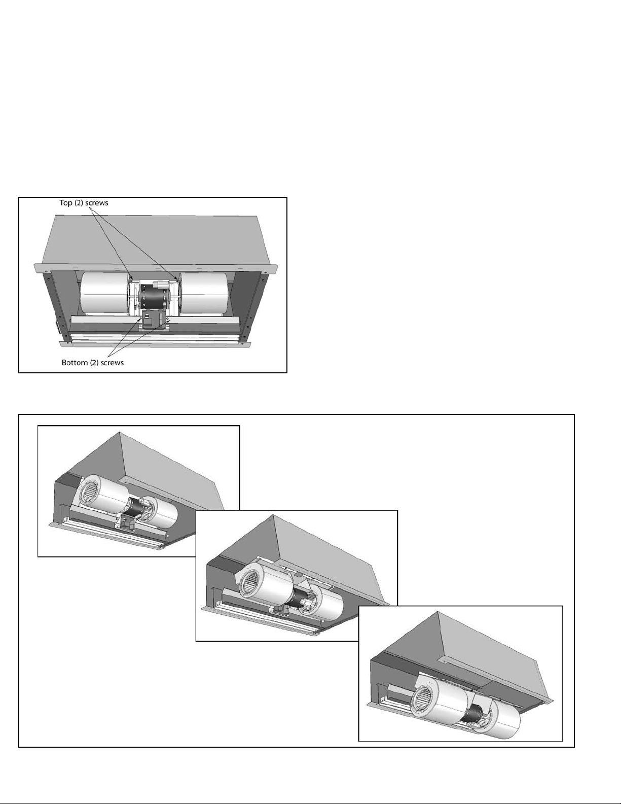
free to drop out of the cabinet. See Figure 8 for location
of all screws.
7. Wearing protective gloves, hold the module by the motor, and rotate the module top forward and drop it down
through the bottom of the unit. See Figure 9.
8. To remove the fans and/or motor, loosen the set screws
in the fan wheel hubs by using a 5/32” Allen wrench
that is at least 6” long. The set screw can be accessed up
through the fan’s discharge.
9. Next, remove the two blower housings by removing the
(8) screws that attach the fan housings to the blower
plate. When the fan housings are free, slide them and
their fan wheels o to each side.
10. Remove the motor clips from the motor mounts, disconnect the motor ground wire if necessary, and lift the
motor up and out of its cradle.
11. Reinstall in reverse order of removal.
B. To Replace the Electric Heater:
1. Disconnect and lockout power to the unit.
2. Remove the bottom access cover.
3. The blower module does NOT need to be removed from
the unit to replace electric heaters, unless you have one
of the following models: ICA1036, ICA2060, or ICA3096.
If you have one of these models, you will need to remove
the blower module to replace the outer heaters. If you
need to remove the blower module, see Section VIII
Service, A.
4. Label and detach the heater connections for supply
power and for the auto reset thermal cutout.
5. Remove the (2) self drilling, heater retention screws holding the electric heater frame to the fan housing. See
Figure 10.
6. Carefully maneuver the heater out from the fan and
Figure 8
Figure 9
6
Page 7

Figure 10
around the motor shaft.
7. Remove the pigtails from the old heater thermal cutout, and place them on the new heater.
8. To install the new heater, maneuver it into position making sure the frame of the heater sits in its cradle, which is attached to
the fan. See Figure 11.
9. Reinstall the (2) self drilling screws using the existing holes in the fan housing. As the fan housings are constructed of thin
gauge steel, be careful not to strip these holes.
10. Reconnect supply power and thermal cutout wiring.
Figure 11
End of Section
See the following pages for information on the Intelliswitch®, including:
Quick Start Operation Guide, FAQ’s, and Detailed Programming Guide.
7
Page 8

that comes with a factory installed digital programmable controller called the Intelliswitch®
INTELLISWITCH® QUICK START OPERATION
When power is turned on to the Air Door, all of the lights on the display will light briey while the
Intelliswitch® starts up. After startup the clock will then display. The Intelliswich is now ready to set.
To operate the air door:
Press the Down Arrow (Menu) button once.
NOTE: If the Down Arrow button is pressed
twice, the function will change from “Mode” to
“Fan Speed”.
Using either the Left or Right Arrow buttons,
scroll through the Modes of Operation until you
reach the desired mode.
See below to determine which mode is right for you.
How to operate your In-Ceiling Mount Air Door
www.intelli-how2.com
NOTE: To adjust the clock, refer to section 4.5 Appendix A.
Mode/Fan Speed indicator will light
For detailed information of the Intelliswitch® Navigation and Operation please refer to Appendix A (see pages 12-18)
Once the Mode of Operation is selected, press
“OK” button to set and return to the clock or the
down arrow to select and adjust any of the other
available settings.
Mode of Operation:
OFF
ON
The unit will not run.
OFF
The unit will run continuously unless a
start and stop time is programmed.
The following modes can be customized see “Programming the Intelliswitch®” for more info.
ON
AUTO
“delu”
DELUXE
For use with a door switch, the unit will operate
only when the door is open.
For use with a door switch, the unit will operate
only when the door is open with a minimum 1
minute delay before turning o when it closes.
8
AUTO
delu
Page 9

Modes of Operation continued:
The following modes can be customized see “Programming the Intelliswitch®” for more info.
For use on heated units only, requires a door
switch. When the temperature drops below the
thermostat set point and the door is closed, the
“PluS”
COMFORT
PLUS
“Pro1”
PROGRAM 1
unit will activate on a low speed and provide
supplemental heating to the space. The unit will
change to normal speed when the door is open.
If the thermostat is still not satised when the
door closes the unit will return to low speed until
the set point is reached.
Recommended for unheated units. This setting
will enable the air door to operate on Deluxe
mode with a 1 minute time delay, 24 hours a
day, 7 days a week.
See Appendix A page 18 for more detailed
information.
PLUS
PRO1
“Pro2”
PROGRAM 2
“Pro3”
PROGRAM 3
Recommended for heated units.
This setting will enable the air door to operate
on Deluxe mode with a 1 minute time delay from
8:00 am – 5:00 pm.
From 5:01 pm – 7:59 am, the unit will operate on
Comfort Plus with a 30 second time delay.
See Appendix A page 18 for more detailed
information.
Recommended for heated units. This setting
will enable the air door to operate on Auto
mode with a 30 second time delay, 24 hours a
day, 7 days a week.
See Appendix A page 18 for more detailed
information.
PRO2
PRO3
9
Page 10

INTELLISWITCH® FAQ’s (Frequently Asked Questions)
www.intelli-how2.com
WARNING: TO REDUCE THE RISK OF FIRE, ELECTRIC SHOCK OR INJURY TO PERSONS, OBSERVE THE FOLLOWING:
Before servicing or cleaning unit, switch power o at service panel and lock the service disconnecting means to
prevent power from being switched on accidentally. When the service disconnecting means cannot be locked,
securely fasten a prominent warning device, such as a tag, to the service panel.
Even though every In-Ceiling Mount unit is individually tested at the factory before shipment,
on occasion improper functionality may be experienced. Here is a list of common questions:
Q. Why can’t I change my settings?
A. The Intelliswitch® may be locked. If the Lock light is illuminated, the control is locked. To unlock, press and hold the left &
right arrows simultaneously for 5 seconds. The Lock mode can
also be protected with a PASScode. If the PASScode option is
on, an attempt to unlock the control will display PASS and then
a 0000 prompt. A four-digit code (available in the installation
instruction book Appendix) must then be entered to unlock
the control. Use the up and down arrows to select a number
and the left and right arrows to select the digit to edit. Press OK
when done. Note: If the AutoLock setting is on, the control will
re-lock if there is no activity after 5 minutes.
Q. Why won’t my heat work, even though fans are running?
A. The thermostat(s) or speed sensor may need adjusted or
replaced.
1.) Make sure that the thermostat probe and/or remote thermostat are in the “On” position and set above ambient (room)
temperature.
2.) Check internal and external thermostat status in the Diagnostics Menu for a faulty thermostat. To do this, hold the right
arrow for ve seconds until DIAG appears, then arrow down to
the ts setting, if it displays “1” then the thermostat(s) is working
(there is a call for heat).
3.) If no external thermostat is used, check to see if the internal
probe is attached to the control board. Disconnect power to
the unit, remove the display board and check that the beige
sheathed cable is attached at both ends. If the thermostat(s)
and settings are correct and you are still not getting heat, then
check to see the fan speed. to do this, press the down arrow to
reach the Mode/Fan speed setting. Use the right and left arrow
to change the fan speed.
4.) Check to see if you can adjust the fan speed. If the speed
sensor is bad there will be no speed control and the Intelliswitch® will not let the heat come on. If it is too dicult to determine a change in speed, the speed sensor can be checked by
entering the DIAG menu and checking the rst error code. If ER
10 displays, the speed sensor is recognized by the Intelliswitch®.
If the code ER 11 is displayed, the Intelliswitch® does not recognize the sensor, and it may be faulty or need adjusted closer to
the trigger bar. Turn o the power to the unit and remove the
screen to check the distance between the sensor and the trigger located on the left side of the motor (use the bottom access
cover for steam/hot water heated units). The sensor should be
less than 1/16” from the trigger face. Check distance at both
ends of trigger. Adjust if necessary.
5.) If there is still no heat or speed control, you may need a new
speed sensor: consult factory.
Q. Why won’t the Intelliswitch® light up?
A. There may not be power to the control.
1.) Check to see if the main power is turned on to the unit. Your
air curtain may have multiple disconnects, be sure all are turned
on.
2.) Verify that there is power to the board. NOTE: ONLY QUAIL-
IFED PERSONS SHALL CHECK POWER IN THE UNIT WITH THE
POWER ON. The power terminals are located directly behind
the display. Remove two Phillips screws from the Intelliswitch®
display to expose the power terminals and check the line voltage at spade terminals L2 and 120, 208 or 240 (depending on
the voltage supplied to the unit).
3.) Check the ribbon cable connections to the display board for
a loose connector or improperly connected cable (see Installation Instructions for correct cable connection).
4.) If there is line voltage power at the board terminals, the ribbon cable is correctly connected, and it is still not working, you
may need a new circuit board: consult factory.
5.) If there is line voltage power at the board terminals, the
ribbon cable is correctly connected, the speed sensor and the
thermostat are working, and it is still not working, you may
need a new circuit board: consult factory.
Q. Why won’t my fans shut o?
A. The Intelliswitch® may be in the wrong mode or mis-wired.
1.) Check to see if the control is in the “ON” mode, if it is, then
change the Mode to another setting.
2.) The T-Stat Mode may be set to the “both” setting and the
thermostat is calling for both Fan and Heat, change the T-Stat
Mode to “HEAT”.
3.) If there is a door switch and the unit is in a mode that is activated by it, there could be a short, mis-wiring or mixup in components. Close the door and check the door switch status in the
Diagnostics menu. Hold the right arrow for ve seconds until
DIAG appears, then arrow down to the ds setting, if it displays
“1” then the door switch signal is closed (there is a call for fan). If
the door is closed, the signal should be “0” or open.
4.) There could be a short in the eld connections to the door
switch or the door switch leads could be mis-wired. To test,
disconnect the door switch connection at the unit. Opening the
wiring tray on top of the unit and be cautious of high voltage
connections. Disconnect the blue wires labeled 9 & 10 from the
eld wiring to the door switch or make sure they are not tied
together. There is no danger of getting shocked because the
signal is 5 volt dc. Be sure not to touch the blue wires to anything metal (or grounded). The unit should shut o when it is in
any mode that is activated by the door switch.
5.) If the air curtain is heated, make sure that the thermostat
isn’t wired to the door switch leads. Door switch leads are blue
and labeled 9 & 10.
10
Page 11

INTELLISWITCH® FAQ’s Continued (Frequently Asked Questions)
www.intelli-how2.com
Q. How can I check the door switch to be sure it’s working?
A. The Intelliswitch® may be in the wrong mode, be mis-wired
or have a faulty door switch.
1.) Test the wiring and controller function at the same time rst.
Locate the door switch and open its wiring compartment by removing the two screws holding on the back cover. There should
be two wires connected to screws inside the switch. There is no
danger of getting shocked because the signal is 5 volt dc. Be
sure not to touch the wires to anything metal (or grounded).
Either disconnect both wires from the screws (noting which
screws the wires are under) and touch them together (with air
curtain in “Auto” mode) or make a short jumper wire and touch
the jumper to both screws at the same time to see if air curtain
comes on. If it does, the controller and wiring work.
2.) If the wiring and unit pass the function test, the problem
could be either misalignment or a faulty door switch. On a
magnetic reed switch check for magnet alignment, for plunger/
roller type switch, check contact engagement with door.
3.) If you have access to an electrical test meter, the door switch
contacts can be tested for continuity when the door switch
wires are disconnected from the unit.
Q. Why won’t my heat shut o?
A. The Intelliswitch® may need adjusted, have been mis-wired
or have a faulty thermostat.
1.) Heat is activated by one of two thermostat connections.
To test the internal thermostat set the external thermostat to
OFF. The settings of the unit mounted thermostat probe are
accessed through the display. Press the down arrow until the
Temp Set indicator lights up; check if the temperature setting
and unit of measure are correct. Test to see if it shuts o by setting the thermostat temperature to OFF or lower than the room
temperature.
2.) If an external thermostat is connected to the unit, there
could be a short in the eld connections or the thermostat
leads may be mis-wired. To test the external thermostat set the
internal thermostat to OFF. Disconnect the external thermostat
connections at the unit. Open the wiring tray on top of the unit
and be cautious of high voltage connections. Disconnect the
orange wires labeled 6 & 7 from the eld wiring to the thermostat or make sure they are not tied together. There is no danger
of getting shocked because the signal is 5 volt dc. Be sure not
to touch the orange wires to anything metal (or grounded). The
heat should shut o when the wires are separated.
For more complex troubleshooting of either thermal cutouts or
heater contactors, please consult a qualied electrician or the
factory.
Q. Why didn’t the Intelliswitch® save the changes I made to
a program?
A. If a program is active (a dot is illuminated by one of the
clock digits), changes can be made to any settings on the User
Menu. These changes however will only remain in eect until
the program changes to the next time zone. To make changes
permanent, settings must be changed in the program from the
Program Menu. Access the Program Menu by holding down the
left arrow for 5 seconds until “PRO” is displayed. Arrow down
to select programming and arrow left to select the program to
edit. Use the down arrow to step through the options and make
changes as desired. Continue to press the down arrow until Stor
is displayed. Press OK or down to keep or store the changes.
Q. How do I undo a change that I made to a program in the
Program Menu?
A. Changes to programs cannot be undone. The programs can
however be reset to the factory default settings. This must be
done on the Factory Menu. Access to the Factory Menu is attained through the Diagnostics Menu. Press and hold the right
arrow for 5 seconds until “DIAG” is displayed. From the “DIAG”
display press and hold the up and down simultaneously for 10
seconds until “FACT” is displayed. Use the down arrow to select
“DEFn” on the display then use the right arrow to select “DEFP”.
Press “OK” to reset. The control display will go blank then blink
as conrmation.
Q. My air curtain won’t turn on?
A. Check the AM/PM setting on the Start and Stop times or the
clock (considering the AM indicator light whensetting values).
Note: set the start time and stop time to the exact time for the
unit to be active full time. Check to see if a program is active
that may have dierent start/stop times than those expected.
Q. My building has a Building Management System, can the
Intelliswitch® work with a BMS?
A. The Intelliswitch® can be controlled by a Building Manage-
ment System (BMS) but currently does not have the ability to
communicate with them. Dry contacts on the BMS may be used
to control the unit activation through the door switch connections (blue wires 9 & 10) and the heat activation thought the
remote thermostat connections (orange wires 6 & 7). Consult
factory.
11
Page 12

A. PROGRAMMING THE INTELLISWITCH®
To reduce the risk of injury and ensure proper
operation all Notes and Instructions shall be read!
Note: The STOP button is available at all times and immediately stops the unit for an emergency situation. The
Intelliswitch® will display STBY for Stand By when selected.
To release the control from STBY press STOP again. When
the control is released from STOP it will be in the OFF Mode.
Press the left or right arrows to select new Mode or OK to
return to the clock.
STOP
2.1. Single Level Options
Single level options can change values directly with the left and
right arrows. No additional actions are necessary to access these
option settings.
2.2. Multi-level Options
Multi-level options require additional actions to access an option’s settings. The right or left arrow is required to enter into an
option.
If the multi-level option has one value to edit it may be changed
directly with the up or down arrow.
If the multi-level menu option has two values (such as a time
value) the rst option value ashes upon selection. Use the left
or right arrow to select which value to change and then use the
up and down arrows to change the option value. See the Menu
Options section for the option increment i.e. hours/minutes,
minutes/seconds.
To leave a multi-level option, use the left or right arrow to cycle
through the option value until it stops ashing. The up or down
arrow may now be used to navigate to the other options.
Note: When changing options, if there is no activity for 15
seconds, the control will save changes and default back to
the User Menu display clock.
Note: The OK button always saves the current entered
value and returns you to the User Menu display clock.
Section 1: Quick Start Reference
Section 2: Arrow Navigation
Section 3: Menu Structure
Section 4: User Menu
Section 5: Program Menu
Section 6: Diagnostic Menu
Section 7: Factory Menu
Section 8: External Connections
1. Quick Start Reference
1.1 Press the Menu button (down Arrow).
1.2 Using the left and right arrows, select the operating Mode:
O, On, Auto, Deluxe, Comfort Plus or Program Number 1, 2
or 3.
1.3 Press OK.
2. Arrow Navigation
The up and down arrows select the menu options.
3. Menu Structure
The Intelliswitch® has four menus:
• User Menu (Section 4)
• Program Menu (Section 5)
• Diagnostic Menu (Section 6)
• Factory Menu (Section7)
The User Menu is the top level menu where values for each option is entered based on the Mode selected. Each option is identied by a green light when selected. The clock display is the
default home position for the User Menu when OK is selected or
there is no activity for 15 seconds.
Note: Access to all Secondary Menus must originate from
the User Menu. Secondary menus are identied by the
menu title upon successful entry, e.g. PRO, DIAG and FACT.
The Program Menu is used to edit all program option parameters.
The Diagnostic Menu is used to diagnose and troubleshoot
errors with the Intelliswitch®.
The Factory Menu is only to be used when directed to reset or
change factory default settings.
The left and right arrows change values for single-level
menu options (Mode, Speed, Temp Degree, Temp Set, T-stat
Mode and Day) or are used to enter into multi-level menu
options (Delay Time, Temp Set, Start Time, Stop Time and Set
Time).
Arrow sequence and available settings are illustrated under
each option.
4. User Menu
To enter into the User Menu press the down arrow (menu). Use
the down or up arrow to step through each option. Each option
is identied by a green light when selected. Options available
from the User Menu are:
12
Page 13

• Mode
• Fan Speed
• Time Delay
• Thermostat degree type
• Thermostat Set Point
• Start Time
• Stop Time
• Thermostat Control Mode
• Time Set
• Day Set
• Lock/PASScode
4.1. Mode: single-level
Select option with right arrow, use up & down arrows to set the
amount of time that the unit will delay shutting o after terminals 9 & 10 are opened.
4.4. Temp Set (units): single level
N °F – °C O
Use left & right arrows to select the temperature degree type,
Fahrenheit or Celsius, for thermostat set point.
Note: This option is only available for heated units with a
built-in thermostat.
NOFF-ON-AUTO-DELU-PLUS-PRO1-PRO2-PRO3 O
Use left & right arrows to select the desired operating Mode.
• OFF – unit o.
• ON – unit will run when start/stop time is satised.
• AUTO – unit will run when terminals 9 & 10 are connected
through a switch and start/stop time is satised, ALL menu
options available.
• DELU – unit will run when terminals 9 & 10 are connected
through a switch and start/stop time is satised, MUST set
time delay from 1-10 minutes, T-Stat Mode NOT available.
• PLUS - unit will run when terminals 9 & 10 are connected
through a switch and start/stop time is satised, when door
is closed and temperature drops below the set point the unit
will run on low speed with heat (low speed set on the Program
Menu), unit will run at higher user level set speed when door
opens.
• PRO1 – Runs Program #1 see Program Menu Section, 1st digit
indicator light when active.
• PRO2 – Runs Program #2 see Program Menu Section, 2nd digit
indicator light when active.
• PRO3 – Runs Program #3 see Program Menu Section, 3rd digit
indicator light when active.
NOTE: When Program Modes are selected changes can only
be made to the Mode, Time Delay, Temperature, Time and
Day settings. Changes will only remain in eect until the
program changes between active time zones.
NOTE: AutoLock, Comfort + Low Speed and PASSCode are
global options and their settings are the same for any Mode
selected. They will not change when the Mode or Program
changes.
4.2. Fan Speed: single-level
4.5. Temp Set : single level
N OFF – 34°F thru 90°F O
or
N OFF – 1°C thru 32°CO
Use left & right arrows to select the temperature set point when
the heat is to be activated.
Note: This option is only available for heated units with a
built-in thermostat.
4.6. Start Time: multi-level – hours/min
Select this option with right arrow, use up & down arrows to set
the time that the unit is to turn on in the ON Mode or become
active for AUTO, DELU and PLUS Modes.
Note: to turn o this feature the Start Time must be set
equal to Stop Time (including am/pm).
4.7. Stop Time: multi-level – hours/min
Select this option with right arrow, use up & down arrows to set
the time that the unit is to turn o in the ON Mode or become
active for AUTO, DELU and PLUS Mode.
Note: to turn o this feature the Start Time must be set
equal to Stop Time (including am/pm).
4.8. Thermostat Mode: single level
N HEAT-BOTH O
Select the control mode for the built-in and remote thermostats.
SP N1-2-3O
Use left or right arrows to select fan speed. Depending on the
Air Curtain Series, the ranges will be either 1-10, 1-3 or 1-2 with
1 = low, and the highest number = high speed.
4.3. Delay Time: multi-level – min/sec
NOFF – 00:01 thru 10:00 O
The HEAT mode only cycles the heater when there is a call for
heat from either internal or external thermostats when the fan
is running. The BOTH mode cycles both the fan and the heater
on a call for heat from either internal or external thermostats.
Note: This option is only available for electric heated units
with built-in thermostat or units with external remote
mount thermostat connected between terminals 6 & 7.
13
Page 14

4.9. Set Time: multi-level – hours/min
Select option with right arrow, use up & down arrows to set the
clock. Note: time does not adjust for daylight savings time.
4.10. Set Day: single level
Use the Program option to select and save User Menu settings
to be recalled at anytime.
A time zone is the period of time dened by the user for the
unit to be active. Both zones may operate one after the other or
with a gap between them.
N DAY1-DAY2-DAY3-DAY4-DAY5-DAY6-DAY7 O
Use left & right arrows to select day of the week, where Sunday
= DAY1, Monday = DAY2 etc. Used as reference by programs.
4.11. Lock/Unlock
The Intelliswitch® can be locked to prevent unauthorized tampering of the settings.
When locked, only the options on the User Level may be
viewed. Only the Mode can be changed between OFF and the
Mode that was active when it was locked, all other options may
NOT be changed.
To lock or unlock, press and hold the left and right arrows simultaneously for 5 seconds, the Locked light will illuminate when
locked.
If the PASScode option is ON, an attempt to unlock the control
will display PASS and then a 0000 prompt to enter a four digit
unlock code. Use the up & down arrows to change the numbers
and the left & right arrows to move between positions.
Note: When the AutoLock option is set to ON in the Program
Menu, the Intelliswitch® will automatically lock after 5 minutes without any activity. Default setting – OFF. See Section
5.2.
Note: When the PASScode option is set to ON in the Factory
Menu, the Intelliswitch® will require a code be entered to
unlock the control. Default setting – OFF. See Section 7.4.
5. Program Menu
The Program menu allows parameters for the following options
to be set:
• Number of Zones: 1 or 2
• Days of the week to operate per zone
• Mode (O-On-Auto-Deluxe-Plus)
• Speed
• Time Delay
• Thermostat Set Point
• Start Time
• Stop Time
• Thermostat Mode
To enter into the Program menu press the down arrow (menu
button) at the PRO display. Use the left & right arrows to select
the program to be edited.
N PRO1-PRO2-PRO3 O
Note: After setting the number of zones and active days all
parameters are set the same as the User Menu. Use the Up
and Down arrows to accept changes and OK to return to
User Menu.
5.1.1. Zone: single level
N Zn 01-Zn 02 O
Select the number of Zones for the program. If one zone is
selected a prompt will ask to save settings after the last option.
If two zones are selected, Zone 1 parameters will be set rst and
then parameters for Zone 2 will be set. A prompt will ask to save
settings after the last option of Zone 2.
To enter into the Program Menu hold down the left arrow for 5
seconds. PRO will display when the Program Menu is available.
Use the Program Menu to set the following options:
• Program 1, 2 & 3 settings
• AutoLock setting
• Comfort Plus low speed setting
• Master/Slave Stand By setting
N PRO-AULC-PLUS-STBYO
Program Menu – single level
Use left & right arrows to select the option to change.
5.1. Program
The Intelliswitch® can store up to three Dual-Zone programs.
5.1.2. Day: multi-level
" day-day1-day2-day3-day4-day5-day6-day7 "
Select the days of the week that the program is to operate for
each zone.
When day is displayed, press the right arrow to enter into the
day parameters.
Once in the day parameters each day is identied by the day
number, use the right or left arrows to select yes to active a day
or no to deactivate a day.
14
Page 15

N dy 1n-dy 1yO
i
N dy 2n-dy 2y O
i
N dy 3n-dy 3y O
Use the up and down arrows to move to the next day or skip
days until day is displayed.
From this point enter right to re-enter day settings or down to
continue.
Use the right or left arrows to select yes to save program or no
to abandon changes.
A single zone program will prompt to save all options after the
rst set of parameters; a dual zone program will prompt to save
after the second set of parameters.
Note: Upon saving, the LED on the digit light corresponding
to the program number will blink.
5.2. AutoLock: multi-level
Note: The top seven LED’s will light from the top down representing days 1 thru 7 that have been activated.
5.1.3. Mode: single level
Select operating mode for Zone. Only O, On, Auto or Plus are
available.
5.1.4. Fan Speed: single level
Select the fan speed for Zone being programmed.
5.1.5. Time Delay: multi-level
Set the time delay for Zone being programmed.
5.1.6. Temperature Set: single level
Set the temperature set point for internal thermostat for Zone
being programmed. Degree type is based on degrees selected
on the User Menu.
5.1.7. Start Time: multi-level
Set the start time for Zone program to activate including am/
pm.
Note: Zone 1 has priority over Zone 2 and if conicting
times are entered Zone 1 will always activate and take precedence over Zone 2.
N ON-YES O
To enter into the AutoLock menu press the down arrow (menu
button) at the AULC display. Use the left or right arrows to se-
lect ON to have control automatically lock if there is no activity
for 5 minutes or OFF to deactivate.
5.3. Comfort Plus (fan speed): multi-level
SP N 1-2-3 O see Note*
To enter into the Comfort Plus low speed setting, press the
down arrow (menu button) at the PLUS display. Use the left or
right arrows to select the low fan speed for the unit when in the
PLUS mode, when the door is closed and the thermostat set
point is reached.
*Note: the speed range is limited to be equal to or less than
that of the User Menu speed setting.
5.4. Master/Slave Stand By: multi-level
N ind-ALL n O
To enter into the Master/Slave stand by setting press the down
arrow at the STBY display. Use the left or right arrows to select
the STOP button behavior when units are connected together
in a Master/Slave conguration. Select “ind” or independent to
stop only the unit where STOP is pressed. Select “ALL” to stop all
connected units.
5.1.8. Stop Time: multi-level
Set the stop time for Zone program to activate including am/
pm.
Note: Zone 1 has priority over Zone 2 and if conicting
times are entered Zone 1 will always activate and take precedence over Zone 2.
5.1.9. Thermostat Mode: single level
Set thermostat mode for Zone.
5.1.10. Store: single level
N str y-str n O
6. Diagnostic Menu
To enter into the Diagnostic Menu hold down the right arrow
for 5 seconds. DIAG will display when the Diagnostic Menu is
available.
The Diagnostic Menu is used to diagnose and troubleshoot Intelliswitch® errors. Only “live” parameter settings are displayed,
there are no options to change.
The Diagnostic Menu displays the following parameters:
• Software version release
• Speed Range Setting
• Internal Thermostat reading – Celsius
• Internal Thermostat reading – Fahrenheit
• Motor rpm reading
15
Page 16

• Supply Voltage Frequency
• Door Switch status
• External Thermostat status
• Heater Relay status
• Error Code 1 – Speed Sensor
• Error Code 2 – Line Frequency
• Error Code 3 – Power Issue
• Error Code 4 – Motor O Fault
will reset all settings (except for Speed Range) back to Factory
default values. Because some speed ranges are not compatible with all motors, the proper value cannot be automatically
set and therefore requires user input. This is prompted by the
scrolling “Set FACt SPEEd” on the display.
Solution – press the “OK” button. This will open the range setting identied by “rn”. Select the correct speed range (see Section 7.1) based on the Series/Model. Press “OK” button.
6.1. Software Release Version – Format: rX.XX
6.2. Fan Speed Range – rn XX (see Section 7.1)
6.3. Thermostat Probe – Pr XX (see Section 7.2)
6.4. Internal Thermostat – ºC (np = no probe)
6.5. Internal Thermostat – ºF (np = no probe)
6.6. Motor RPM – measured speed in rpm
6.7. Supply Voltage – measured frequency in Hz
6.8. Door Switch Status – 0=open, 1=closed
6.9. External T-stat Status – 0=open, 1=closed
6.10. Heater Relay Status – 0=open, 1=closed
6.11. Error Codes
The Intelliswitch® has six error codes, 1 through 6, to help
troubleshooting. The status of 1-4 can be observed from the
Diagnostic Menu. The format for displaying the error code is the
“Er” descriptor and a two digit code. The rst digit is the error
number and the second digit is the status using international
convention. 0 = inactive, 1 = on or active.
6.11.1. Error Code 1 – Speed Sensor
Er 10 – Prox Sensor or Speed feedback exists
Er 11 – NO Prox Sensor or Speed feedback
Solution – check to see if the proximity sensor (located next
to the motor) is connected to the control board and check
distance between tip and trigger bar is approximately 1/16 of
an inch.
6.11.2. Error Code 2 – Line Frequency
Er 20 – power supply line frequency exists
Er 21 – undetermined supply line frequency
Solution – The Intelliswitch® automatically senses line frequency. In the event that it can not determine the proper line
frequency, it will run at full speed and ash error. Manually set
the line frequency in the FACT menu. See Section 7.5.
6.11.3. Error Code 3 – Zero Cross/Power Issues
Er 30 – clean power exists
Er 31 – poor power exists, electrical noise
Solution – When the control encounters “noise” in the electrical
power supply it will run at full speed and ash error code. There
are no internal changes available. Have the electrical system
checked for problems.
6.11.4. Error Code 4 – Speed Feedback
Er 40 – proper motor and sensor operation
Er 41 – Motor o but receiving prox/speed sensor feedback
Solution – this is usually the result of a failing motor control
component on board that cannot be serviced. A replacement
board is required.
6.11.5. Error Code 5 – Corrupted Memory Setting
Er 51 – Status of this error is not available. It only appears when
there has been an event that has corrupted the settings in
memory. When corrupted settings are identied the control
6.11.6. Error Code 6 – Incompatible Speed Range for Master/Slave Operation
Er 61 – Status of this error is not available. It only appears when
unit are connected in a Master/Slave conguration that do not
have identical Speed Range settings.
If two units are connected without equivalent speed ranges,
every time a button is pressed on the Master unit (the unit used
to make setting selections) the Slave unit will display an “Er 61”
and the Slave will ignore the command to protect the control
from damaging the motor.
Solution – Enter the Factory Menu to select the proper Speed
Range (See Sections 7 and 7.1)
Note: This error does not monitor if the correct speed range
has been selected for a Series/Model. Only that two or more
units have been connected that do not have equivalent
speed ranges.
Note: Once the correct speed ranges are selected and the
controls accept commands from one another, the controls
should be synchronized by simply cycling through all of the
settings on the User Menu using the up or down arrows.
None of the settings need to be changed.
7. Factory Menu – Service Personnel Only
The Factory Menu must be entered from the DIAG header. To
enter into the Factory Menu hold down the right arrow for 5
seconds. DIAG will display when the Diagnostic Menu is available. From the DIAG display, press and hold the up and down
arrows simultaneously for 5 seconds. FACT will display when the
Factory Menu is available.
Note: When the Factory Menu is accessed it automatically
shut the unit o by changing the Mode to OFF.
The Factory Menu is used to change or reset core settings to
change base functions or resolve Intelliswitch® errors.
The Factory menu allows parameters for the following options
to be set:
• Speed Range Setting
• Restore Factory Default Settings
• Reboot Software
• PASScode
• Supply Voltage Frequency
To enter into the Factory Menu from the header press the down
16
Page 17

arrow. Use the left & right arrows to change setting values. Use
the OK button select action and return to the User Menu.
7.1. Speed Range: single level
rn N 0 – 1 – 2 – 3 – 4 – 5 – 6 – 7 –8 – 9 – 10 -11 – 99 O
Select the fan speed range from 0 to 11 using the left or right
arrows. The speed range for each unit is located on the unit wiring diagram called out in a box in the Intelliswitch® schematic
by “SPEED rn __”.
DEFP – reset Programs ONLY settings
DEFA – reset ALL settings (user and program)
DEFt – set controller to factory TEST parameters
7.4. Reboot Software: single level
N reb y – reb n O
If an error occurs that can be xed by rebooting the control
software, select REB using the down arrow. Select YES or NO to
reboot the control.
Note: Selecting the incorrect speed range can damage the
motor(s) beyond repair and potentially create abnormally
high temperatures.
Speed ranges are dependent upon the Air Curtain Series, motor
type and heat option.
ICA/FCA (1/2 hp) – 120, 208 or 240 voltages use range 8 or 9.
480 and 600 volts use ranges 6 or 7.
Motor Control Panel – only 120 volt, use range 3-4
Available ranges are:
0 = ambient – variable 3-speed, 600 rpm to full
1 = ambient – variable 3-speed, 1050 rpm to full
2 = heated – variable 3-speed, 1250 rpm to full
3 = ambient – full on, no adjustment
4 = heated – full on, no adjustment (monitored)
5 = heated – full on, no adjustment (not monitored)
6 = ambient – multiple 3-speed, ITC relay control
7 = heated – multiple 3-speed, ITC relay control
8 = ambient – variable 3-speed, 1250 rpm to full
9 = heated – variable 3-speed, 1250 to full
10 = ambient – multiple 2-speed, ITC relay control
11 = heated – multiple 2-speed, ITC relay control
99 = lock out – scrolling request for user input
7.2. Thermostat Probe Mode: single level
In “St” (Standard) mode the lowest operating point for the
thermostat probe is 34°F (1°C). Below this temperature there
will be no call for heat and “nP” (no Probe) will display on the
diagnostics menu.
In “Cd” (Cold) mode the thermostat will operate below 34°F
(1°C) but disables the “nP” (no Probe) feature and will call for
heat on a probe failure or if it is disconnected.
St - Standard mode, locks out below 34°F (1°C). Cd - Cold
mode, works below 34°F (1°C).
7.3. Restore Factory Default: single level
DEF N n – U – P – A – t O
If it is necessary to restore any of the controls settings back to
the factory defaults, select DEF using the down arrow. Select
the factory setting restore type using the left or right arrows.
This will reset the option settings back to the factory default
settings. Available selections are:
DEFn – no changes
DEFU – reset User Menu ONLY settings
7.5. PASScode multi-level
N PAS y – PAS n O
Select y to enable the PASScode feature and n to disable. When
active, the PASScode feature requires that a four digit code be
entered to unlock the control. The code is: 2376
7.6. Line Frequency: single level
N Fr Au – Fr 60 – Fr 50 O
The Intelliswitch® default is to automatically sense the line voltage frequency. If it cannot be determined automatically, the
line frequency may be manually selected.
Au – Automatically Sense
60 – 60 Hz power supply
50 – 50 Hz power supply
8. External Connections
There are three types of external connections available on the
Intelliswitch®.
• Door Switch
• External Thermostat
• Serial Connection
8.1. Auto Mode Activation
When terminals 9 and 10 in the junction box are connected
(closed), the Auto, Deluxe, Plus and Programmable Modes are
activated. The Intelliswitch® uses a low 5 volt DC voltage signal
to monitor contact closure.
8.1.1. Door Switch (limit switch)
The door or limit switch is used in conjunction with the Auto,
Deluxe, Plus and Programmable Modes to signal that the door
is open. Connect door or limit switch to terminals 9 and 10 in
the unit junction box.
8.1.2. Building Management System
A building management system or dry contact closure can be
used to activate the unit through the Auto, Deluxe, Plus and
Programmable Modes. Connect applicable contacts to terminals 9 and 10 in the unit junction box.
17
Page 18

8.2. Heat Mode Activation
B. USER MENU DEFAULTS
When terminals 6 and 7 in the junction box are connected
(closed), the Heat Mode is activated for all Operating (On, Auto,
Deluxe, Plus and Programmable) Modes. The Intelliswitch® uses
a low 5 volt DC voltage signal to monitor contact closure.
If the internal thermostat is left on, the external heat mode
will operate in parallel to contact closure, allowing either one
to activate the heat. If the internal thermostat is turned o the
external heat mode will activate independently to activate the
heat.
8.2.1. External Thermostat
An external (remote) thermostat connection can be used to
sense temperature independent of the built-in thermostat. Connect thermostat to terminals 6 and 7 in the unit junction box.
8.2.2. Building Management System
A building management system or dry contact closure can
be used to activate the Heat Mode for all Operating Modes.
Connect applicable contacts to terminals 6 and 7 in the unit
junction box.
8.3. Master/Slave Operation
For Master/Slave Operation a serial cable connection must be
made between all Intelliswitch® controls of each unit to be
linked.
Once units are linked all Menu settings made through any unit
display or remote control will transfer to all other linked units.
Parameter changes made on any linked unit will update all
other boards “live” upon menu selections.
9. Infra-red Remote Control
The handheld infra-red remote control buttons layout and
operation are the same as that on the Intelliswitch® unit display
(including multiple button presses) with one exception, the
Lock Button.
There is no need for multi-button press and hold for lock/unlock
activation. The Lock button will lock/unlock display in one press.
NOTE: AutoLock, Comfort+ Low Speed and PASSCode are global
options and their settings are the same for any Mode selected.
They will not change when the Mode or Program changes.
User Menu Default Settings Restore for DEFu:
• Mode: OFF
• Fan Speed: 3
• Time Delay: 15 sec (00:15)
• Thermostat degree type: ºF
• Thermostat Set Point: 68
• Start Time: 8:00am
• Stop Time: 8:00am
• Thermostat Control Mode: HEAT
• Lock: unlocked
• AutoLock: OFF
• Comfort+ Low Speed: 3
• PASScode: n = OFF
NOTE: does not change Speed Range, Time or Day
C. PROGRAM DEFAULTS
Program Default Settings for Restore for DEFp:
Program #1
(recommended for unheated units):
• Number of Zones: 1
• Days of the week to operate per zone: 1 – 7 (all)
• Mode (O-On-Auto-Deluxe-Plus): Deluxe
• Speed: 3
• Time Delay: 1 min (01:00)
• Thermostat degree type: ºF
• Thermostat Set Point: OFF
• Start Time: 8:00am
• Stop Time: 8:00am
• Thermostat Mode: HEAT
Program #2
(recommended for heated units):
• Number of Zones: 2
• Days of the week to operate per zone: 1 – 7 (all)
• Mode (O-On-Auto-Deluxe-Plus):
Zone 1 – Deluxe; Zone2 – Comfort+
• Speed: Zone 1 – 3; Zone 2 – 3
• Time Delay: Zone 1 – 1 min (01:00);
Zone 2 – 30 sec (00 :30)
• Thermostat degree type: ºF
• Thermostat Set Point: Zone 1 – 68; Zone 2 – 62
• Start Time: Zone 1 – 8:00am; Zone 2 – 5:01pm
• Stop Time: Zone 1 – 5:00am; Zone 2 – 7:59am
• Thermostat Mode: HEAT
Program #3
(recommended for heated units):
• Number of Zones: 1
• Days of the week to operate per zone: 1 – 7 (all)
• Mode (O-On-Auto-Deluxe-Plus): AUTO
• Speed: 3
• Time Delay: 30 sec (00:30)
• Thermostat degree type: ºF
• Thermostat Set Point: 60
• Start Time: 8:00am
• Stop Time: 8:00am
• Thermostat Mode: HEAT
18
Page 19

TROUBLESHOOTING
SYMPTOMS REMEDY
NO AIR
MINIMUM AIR
NO SPEED
ADJUSTMENT
AIR IS NOT HITTING
FLOOR
UNEVEN AIR
• Powersupplylineopen(nopower)
• Fuseblown/circuitbreakertripped
• Motoroverloadtripped
• Failedswitch
MOTOR RUNNING/FANS ARE NOT ROTATING
• Brokenfanhub
• Shaftrotatinginsidefan
ELECTRICAL CONTROLS NOT FUNCTIONING WHEN DOOR IS OPEN
• Doorlimitswitchnotoperating
• Airdirectionaldischargevanesmis-adjusted
• Inadequateintakeclearance
• Blowermotoroperatesbelowspeed
• Fanrubbingagainsthousing
• Fanwheelscloggedwithdirt
• Faninbackwards
• Speedsensornotdetecting
triggerrotation
• Airstreamtooweak
• Airsteamhitsobstruction
• Negativepressure
• Shaftrotatinginsidefan
• Onemotornotoperating
CAUSE
• Checkpowersource,checkmethodofcontrolinON
position
• Replacefuse(s)/resetbreaker
• Internallyprotectedmotor-shouldresetautomatically
aftercool-down,ifnot,replacemotor.
• Replaceswitch
• Replacefan
• Tightensetscrews/tightenfanonshaft
• Repairorreplacelimitswitch
• Adjustvanestoproperposition,seeinstructions
• Moveaircurtainorremoveobstruction
• Provideadequatespaceforaircurtain
• Impropervoltage
• Freefanfromhousing
• Cleanandvacuumfanwheels
• Checkfansforbladecurvetowarddischarge
• Adjustgapbetweensensor&trigger/
replacesensor
• Adjustnozzletoproperposition,adjustmotorspeed;
seeinstallationinstructions
• Removeobstructionorrepositionaircurtain(moveout
3/8”forevery1”upfromthedoor)
• Relievenegativepressurebyprovidingmakeupair
• Tightensetscrews
• Repairorreplacemotor
ELECTRICALLY HEATED MODELS
NO HEAT
• Thermostatnotsetproperly
• Coilsburnedoutduetolackofair
• Automaticresetthermalcutoutfailedinopenposition
• Speedsensornotdetectingtriggerrotation
• Withoutspeedadjustment,failedspeedsensor
• Changethermostatsetting
• Correctairowproblem;replacecoils
• Replaceautomaticthermalcutout
• Adjustgapbetweensensorandtrigger
• Replacespeedsensor
MINIMAL HEAT
EXCESSIVE HEAT
EXCESSIVE HEAT
MINIMAL HEAT
• Thermostatinwronglocation-thermostattoo
closetodischarge
• Impropervoltage
• Thermostatnotsetproperly
• Speedsensornotdetectingtriggerrotation
• Thermostatinwronglocation
• Thermostatnotsetproperly
• Insufcientairovercoil
• Impropervoltage
STEAM/HOT WATER HEATED UNITS
• Toohighsteam/hotwaterpressure
• Inadequateairow,nspluggedup,dirtycoils
• Insufcientremovalofcondensation(steam)
• Notenoughsteampressure/watertemperaturetoolow
• Intakeairbelowdesigntemperature
19
• Movethermostatawayfromairstream
• Supplypropervoltage
• Changetemperaturesetting
• Adjustgapbetweensensor&trigger/replacesensor
• Movethethermostatclosertoairstream
• Changetemperaturesetting
• Removerestrictiononintake
• Supplypropervoltage
• Reducesteampressure/hotwaterow
• Cleanintakeandcoils
• Increasetrapsize
• Raisepressureforsteam/increasewaterow
• Increasesteampressure/increasewaterow
Page 20

WARRANTY
Berner International warrants all new equipment to be free of defects in workmanship and material for a period of ve years (5 years)
on unheated models and two years (2 years) on heated models from the original date of shipment, provided the equipment has been
properly cared for, installed and operated in accordance with the limits specied on the nameplate and The Company’s instructions.
The Company will correct by repair or replacement, at its option and expense, any proven defects in said apparatus, subject to the above
conditions, provided that immediate written notice of such defects is given to The Company. The warranty does not include any labor
incurred for the removal or installation of defective part(s). The Company reserves the right to inspect, or have inspected by a qualied
representative, any apparatus at the place of installation before authorizing repair or replacement. Repair or replacement will be made
F.O.B. factory with any applicable transportation charges to be borne by the customer. Merchandise not of The Company’s manufacture
supplied in piece, or in component assemblies, is not covered by the above warranty, but The Company will give the customer the benet
of any adjustment as made with the Manufacturer.
This warranty is void if the apparatus has been tampered with in any way or shows evidence of misuse.
The Company will not assume any expense or liability for repairs made outside its factory without proper written consent from its service
manager, nor for any transportation charges on apparatus returned to the factory without written authorization by The Company.
Nothing in the above warranty provisions, however, shall impose any liability or obligation of any type, nature or description upon Berner
International if Berner has not received payment in full for the apparatus in question.
THERE ARE NO WARRANTIES WHICH EXTEND BEYOND THE DESCRIPTION ON THE FACE HERE OF INCLUDING
THE IMPLIED WARRANTY OF MERCHANTABILITY AND FITNESS FOR A PARTICULAR PURPOSE.
LIMITATION OF DAMAGES
Notwithstanding anything to the contrary above, customer’s exclusive remedy for any and all losses or damages resulting
from the sale of The Company’s equipment under this agreement, including but not limited to, any allegations of breach of
warranty, breach of contract, negligence or strict liability, shall be limited, at The Company’s option, to either the return of
the purchase price or the replacement of the particular equipment for which a claim is made and proved. In no event shall The
Company be liable for any special, consequential, incidental or indirect losses or damages from the sale of The Company’s
equipment under this agreement.
SERIAL NUMBER MODEL NUMBER DATE PURCHASED
BERNER INTERNATIONAL CORPORATION
New Castle, Pennsylvania
724-658-3551 • 1-800-245-4455 • www.berner.com • airdoors@berner.com
Berner reserves the right to alter specifications without prior notice.
© Copyright 2011 Berner International Corporation MADE IN U.S.A.
 Loading...