

Page 1
READ AND SAVE
THESE INSTRUCTIONS
No. II-450
Date January, 2009
DRIVE-THRU UNIT
www.berner.com
800-343-7991
AIR DOOR
MADE IN THE USA
Installation & Maintenance Instructions
TABLE OF CONTENTS
I. UNCRATING.................................................................................................................................................................. 2
II. MOUNTING INSTRUCTIONS ..................................................................................................................................... 2
III. WALL MOUNTING ..................................................................................................................................................... 3
IV. ELECTRICAL CONNECTIONS .....................................................................................................................................4
V. OPERATION AND CONTROLS .................................................................................................................................. 4
VI. AIRFLOW ADJUSTMENTS ......................................................................................................................................... 4
VII. MAINTENANCE AND CLEANING .............................................................................................................................4
VIII. SERVICE ..................................................................................................................................................................... 5
Your new Drive-Thru air door (sometimes referred to as an air curtain) , properly installed, maintained
and operated, will keep fumes out of your restaurant, increase employee comfort, and save energy.
WARNING: TO REDUCE THE RISK OF FIRE, ELECTRIC SHOCK OR INJURY TO PERSONS, OBSERVE THE FOLLOWING:
A. Use this unit only in the manner intended by the manufacturer. If you have any questions, contact the manufacturer.
B. Before servicing or cleaning unit, switch power o at service panel and lock the service disconnecting means to prevent power from being
switched on accidentally. When the service disconnecting means cannot be locked, securely fasten a prominent warning device, such as a
tag, to the service panel.
C. Installation work and electrical wiring must be done by qualied person(s) in accordance with all applicable codes and standards, including
re-rated construction.
D. Sucient air is needed for proper combustion and exhausting of gases through the ue (chimney) of fuel burning equipment to prevent
back drafting. Follow the heating equipment manufacturer’s guideline and safety standards such as those published by the National Fire
Protection Association (NFPA), and the American Society for Heating, Refrigeration and Air Conditioning Engineers (ASHRAE), and local
code authorities.
E. When cutting or drilling into wall or ceiling, do not damage electrical wiring and other hidden utilities.
Page 2
I. UNCRATING
Carefully examine the carton(s) for damage before opening. If
the carton is damaged, immediately notify shipping company.
If the unit(s) were shipped on wooden skids, remove protective wood and banding straps securing the carton(s) to the
skid. Open the carton(s) and remove all protective packaging.
Immediately verify that the electrical rating nameplate located
on the cover matches electrical power supply available. Retain
the shipping carton(s) until the unit(s) is installed and properly
operating.
ACCESSORIES: If the unit(s) was ordered with optional electrical accessories, the accessories may be found in the carton
containing the unit or in a separate carton(s) accompanying
the unit(s). Check all of the cartons/skids for accessories before
discarding.
II. MOUNTING INSTRUCTIONS
(General Notes for All Mounting Congurations)
INDOOR MOUNTING ONLY!
Environmental/Insect/Dust & Fume Control
The Drive-Thru air door is designed to be an eective barrier
against cold drafts in the winter and hot air in the summer. To
achieve optimum protection, the unit should be mounted on
the inside of the building, as close to the top of the window
opening as possible. To ensure peak performance, keep the
air stream free of obstructions. The unit is equipped with
mounting brackets to ensure proper mounting in most applications.
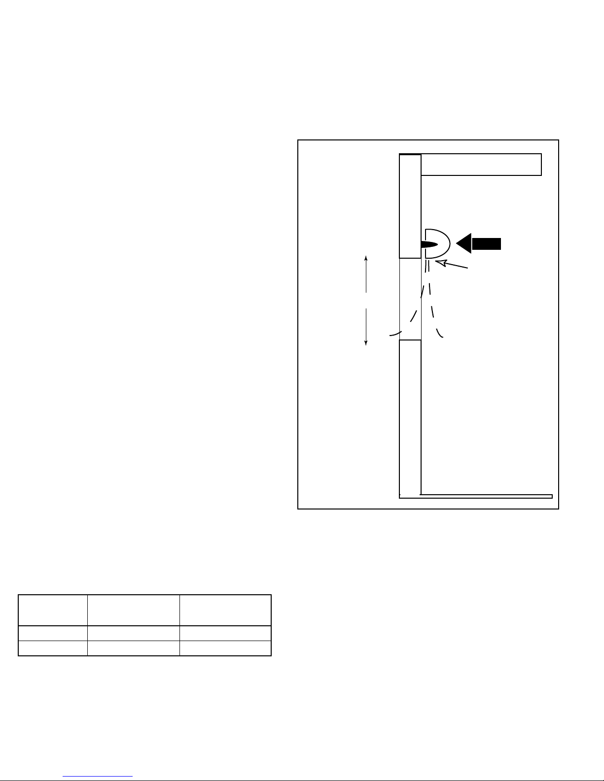
A. When determining the mounting location for the unit(s), make
sure that nothing interferes with the curtain of air developed
when the discharge vanes are directed from 0º to 20º toward
the drive-thru window opening. If the air stream strikes any
obstruction (the top edge of the window, a window opening device, etc.), the eectiveness of the unit will be greatly
reduced (See Drawing 1).
AIR
Discharge
Nozzle
18” minimum
Air
Air
Exterior
Interior
The air door will not perform properly if negative air pres-
sure exists in the building. Under these conditions, a means
for makeup air to the building must be provided so that the
air pressure on both sides of the opening is in balance.
Before mounting the unit, check the supporting structure to
verify that it has sucient load-carrying capacity to support
the weight of the unit(s). The mounting hardware should be
capable of supporting a minimum of three (3) times the weight
of the unit (See Table 1).
MODEL
DTU1018 11 12
DTU1026 16 17
TABLE 1
NET WEIGHT
AMBIENT (lbs)
NET WEIGHT
ELECTRIC (lbs)
DRAWING 1
B. For optimum performance, the bottom of the unit (discharge
nozzle) should be no more than 1” above the top of the
drive-thru window opening with the unit mounted ush to the
wall. If the unit must be mounted higher, it must be spaced
out from the wall 3/8” for every inch the unit is above the
drive-thru window opening.
C. Electric heated units shall:
1. Have a minimum clearance of at least 1” between the sides
and top of the unit and any combustible material.
2. Have a minimum clearance of at least 18” between the bottom of the unit and the counter.
-2-
Page 3

III. WALL MOUNTING
The Drive-Thru Unit air door is shipped with a variety of wall mounting options. Included in standard orders are standard brackets
(See Figure 1) and spanning legs (See Figure 2). Adjustable brackets (See Figure 3) available by special order.
FIGURE 1 -Standard Brackets
FIGURE 2 -Spanning Brackets (works with both standard and adjustable extension brackets)
FIGURE 3 -Adjustable Extension Brackets (optional, must be ordered separately by special order)
-3-
Page 4

Motor Voltages/Amp Draws
DTU1018AA DTU1018EA DTU2026AA DTU2026EA
Volts 120 120 120 120
Phase 1 1 1 1
Hertz 60 60 60 60
Amps per unit 1.6 18.3 2.2 18.9
kW 0 2 0 2
TABLE 2
IV. ELECTRICAL CONNECTIONS
All electrical wiring and connections MUST be performed
by qualied personnel in accordance with the National
Electrical Code ANSI/NFPA No. 70 (latest edition) or, in
Canada, the Canadian Electrical Code, Part 1-C.S.A. Standard
C22.1, and local codes and regulations.
VII. MAINTENANCE AND CLEANING
CAUTION: ELECTRIC SHOCK HAZARD:
Disconnect power when servicing unit.
More than one disconnect may be required to de-energize
unit.
Keep your air door operating at peak eciency by cleaning
the blower wheels, motor(s) and intake grille. Build up of
dust on the blower wheels can cause vibration, noise and
excessive wear on the motor bearings. The frequency of
cleaning will depend on the environment where the unit is
operating.
Dirty, dusty or greasy environments could require a cleaning
schedule of once every two months. If the environment is not
that dirty, the unit(s) should be scheduled for cleaning a
minimum of once every (6) months.
A. Check the rating nameplate on the top of the unit for supply
voltage and current requirements (See Figure 2). Unheated
units may be plugged into any 15 or 20 amp receptacle.
Heated units require a dedicated 20 amp receptacle
and circuit. A disconnect switch for each branch circuit is a
required part of this installation (See Table 2).
B. All eld wiring must be copper with a minimum insulation
of 60°C within approved conduit. If any of the wire supplied
with the unit must be replaced, it must be replaced with
copper wiring with a minimum insulation of 90°C.
V. OPERATION AND CONTROLS
A. The unheated Drive-Thru Unit air door operates with a two
position on-o switch.
B. The heated Drive-Thru Unit air door operates with a three
position fan-o-heat switch.
VI. AIR FLOW ADJUSTMENTS
A. With the air door operating and the door in its full open
position, check to see that nothing is obstructing the air ow
at the discharge nozzle vanes.
B. Find the air stream split location. Hold a handkerchief or
tissue, by its corners, approximately 4” above the counter.
Gently move the handkerchief back and forth in the
doorway. Make sure the air is being directed to both the
inside and the outside. The split location is indicated where
the handkerchief is vertical with minimal or no uttering.
C. Rotate the air curtain by adjusting its position in the
mounting bracket so the split location is approximately 2”
outside the window (See Drawing 1).
To remove the lter:
This unit is equipped with a “No Tool” lter removal. Simply,
pull the (2) black tabs, located underneath the intake grille,
outward. This action releases the lter which then can be pulled
downward out of the unit (See Figure 4).
FIGURE 4 -Filter Removal
To clean the interior of the unit:
A. Disconnect the power to the unit; remove the intake grille by
removing the (4) screws on one side of the unit. Pull the top
of the end cap outward to release the lter tab to remove
end cap. Slide the intake grille out of unit (See Figure 5).
It is not recommended to remove the blower assembly from
the cabinet. To clean the motor and blower wheels, with the
lter and inlet screen removed, blow compressed air in the
unit to remove loose dust and debris.
CAUTION: STAND CLEAR OF THE UNIT OR WEAR SAFETY
GOGGLES AS LOOSE DEBRIS MAY BE PRESENT AND MAY
EXIT THE NOZZLE.
B. Connect power and switch the power on after cleaning.
-4-
Page 5

FIGURE 5 -Removing End Cap
VIII. SERVICE
CAUTION: ELECTRIC SHOCK HAZARD:
Disconnect power when servicing unit.
More than one disconnect may be required to de-energize
unit.
Any service performed on the Drive-Thru Unit air door
MUST be done by qualied personnel.
Berner air doors require very little servicing. All parts are
easily accessible for periodic inspection and maintenance.
Units should be cleaned at least twice a year. Your particular
application (the amount of dirt and dust in the air) and location
of the unit(s) will determine how often your unit(s) will need
to be cleaned and serviced. All motors have permanently
lubricated, sealed, sleeve, or ball bearings and require no
maintenance.
www.berner.com
800-343-7991
A. REPLACEMENT OF ELECTRIC HEATER ELEMENT
1. Disconnect power to the unit.
2. Remove the end cap and intake grille by removing the
screws on one end of the unit and sliding the grille out.
3. Remove and mark all wires from damaged element.
4. To remove damaged element from unit, slide it out
through the front of the unit.
5. Install new element and connect all wires.
6. Reinstall intake grille and end cap.
7. Connect power and turn power on.
-5-
Page 6

WARRANTY
Berner International warrants all new equipment to be free of defects in workmanship and material for a period of one year on unheated
and heated models from the original date of shipment, provided the equipment has been properly cared for, installed and operated in
accordance with the limits specied on the nameplate and The Company’s instructions.
The Company will correct by repair or replacement, at its option and expense, any proven defects in said apparatus, subject to the above
conditions, provided that immediate written notice of such defects is given to The Company. The warranty does not include any labor
incurred for the removal or installation of defective part(s). The Company reserves the right to inspect, or have inspected by a qualied
representative, any apparatus at the place of installation before authorizing repair or replacement. Repair or replacement will be made
F.O.B. factory with any applicable transportation charges to be borne by the customer. Merchandise not of The Company’s manufacture
supplied in piece, or in component assemblies, is not covered by the above warranty, but The Company will give the customer the benet
of any adjustment as made with the Manufacturer.
This warranty is void if the apparatus has been tampered with in any way or shows evidence of misuse.
The Company will not assume any expense or liability for repairs made outside its factory without proper written consent from its service
manager, nor for any transportation charges on apparatus returned to the factory without written authorization by The Company.
Nothing in the above warranty provisions, however, shall impose any liability or obligation of any type, nature or description upon Berner
International if Berner has not received payment in full for the apparatus in question.
THERE ARE NO WARRANTIES WHICH EXTEND BEYOND THE DESCRIPTION ON THE FACE HEREOF INCLUDING
THE IMPLIED WARRANTY OF MERCHANTABILITY AND FITNESS FOR A PARTICULAR PURPOSE.
LIMITATION OF DAMAGES
Notwithstanding anything to the contrary above, customer’s exclusive remedy for any and all losses or damages resulting
from the sale of The Company’s equipment under this agreement, including but not limited to, any allegations of breach of
warranty, breach of contract, negligence or strict liability, shall be limited, at The Company’s option, to either the return of
the purchase price or the replacement of the particular equipment for which a claim is made and proved. In no event shall
The Company be liable for any special, consequential, incidental or indirect losses or damages from the sale of The Company’s
equipment under this agreement.
Berner reserves the right to alter specifications without prior notice.
 Loading...