

Page 1
www.Berner.com
Commercial High Performance 10
Air Curtain Series #CHD10
Sanitation Certied High Performance 7
Air Curtain Series #SHD07
ANSI/NSF 37
Air Curtain Fans
for Customer Entry
12CS
SHD07
for outdoor use
SHD07
FDA
RECOMMENDED
USDA
COMPLIANCE
SHD07
Installation & Maintenance Instructions
TABLE OF CONTENTS
I. UNCRATING............................................................................................................................................................ ........................................................ 2
II. GENERAL MOUNTING INSTRUCTIONS ................................................................................................................................. ................................... 4
III. WALL MOUNTING ...................................................................................................................................................................................................... 5
IV. SUSPENDED MOUNTING ....................................................................................................................................... ................................................... 6
V. ELECTRICAL CONNECTIONS ..................................................................................................................................................................................... 7
VI. FIELD CONNECTIONS ................................................................................................................................................................................................ 7
VII. OPERATING INSTRUCTIONS .................................................................................................................................................................................... 8
VIII. MAINTENANCE AND CLEANING ............................................................................................................................................................................ 9
IX. SERVICE ............................................................................................................................................................... ........................................................ 9
X. TROUBLESHOOTING ................................................................................................................................................................................................. 10
XI.WARRANTY ................................................................................................................................................ ................................................................ 12
Thank you for choosing Berner.
Berner International has been saving energy and creating healthy, comfortable environments for our customers for over 60 years.
Berner oers unmatched quality, performance, and dependability—not to mention our service. At Berner, we stand behind our products.
READ ALL INSTRUCTIONS BEFORE INSTALLING OR USING AIR CURTAIN
1
©Copyright, 2017 Berner International
September, 2017
II-123
Page 2
Commercial High
Sanitation Certied
Performance 10
Air Curtain
(Air Door)
High Performance 7
Air Curtain
(Air Door)
WARNING: TO REDUCE THE RISK OF FIRE, ELECTRIC SHOCK OR INJURY TO PERSONS, OBSERVE THE FOLLOWING:
A. Read all instructions before installing or using this air curtain.
B. Use this unit only in the manner intended by the manufacturer and described in this manual. Any other use not recommended by the
manufacturer may cause re, electric shock, or injury to persons. If you have any questions, contact the manufacturer.
C. Before servicing or cleaning unit, switch power o at service panel and lock the service disconnecting means to prevent power from
being switched on accidentally. When the service disconnecting means cannot be locked, securely fasten a prominent warning device,
such as a tag, to the service panel.
D. Installation work and electrical wiring must be done by qualied person(s) in accordance with all applicable national and local codes
having jurisdiction, including re-rated construction. See page 7, ELECTRICAL CONNECTIONS (NEC Code ANSI/NFPA No. 70).
E. When cutting or drilling into wall or ceiling, do not damage electrical wiring and other hidden utilities.
F. To reduce the risk of re, do not store or use gasoline or other ammable vapors and liquids in the vicinity of the air curtain.
G. This air curtain is hot when in use. To avoid burns, do not let bare skin touch hot surfaces. Keep combustible materials, such as furniture,
pillows, bedding, papers, clothes, etc. and curtains at least 1 inch from the top, back, front, sides and at least 6 feet from the discharge
of the air curtain.
H. Extreme caution is necessary when any air curtain is used by or near children or invalids, and whenever the heater is left operating
unattended.
I. Do not operate any air curtain after it malfunctions. Disconnect power at the service panel and have the air curtain inspected by a
reputable electrician before reusing.
J. To disconnect the air curtain, turn controls to "o", and turn o power to the air curtain circuit at main disconnect panel.
K. Do not insert or allow foreign objects to enter any ventilation or discharge opening as this may cause an electric shock or re, or
damage the air curtain.
L. To prevent a possible re, do not block the air intake or discharge of the air curtain in any manner.
M. The air curtain has hot and arcing or sparking parts inside. Do not use it in areas where gasoline, paint, or ammable vapors or liquids
are used or stored.
N. This heater may include an audible or visual alarm to warn that parts of the heater are getting excessively hot. If the alarm sounds
(or illuminates), immediately turn the heater o and inspect for any objects on or adjacent to the heater that may have blocked the airow
or otherwise caused high temperatures to have occurred. DO NOT OPERATE THE HEATER WITH THE ALARM SOUNDING (OR ILLUMINATING).
I. UNCRATING
Carefully examine the carton(s) for damage. If the carton is
damaged, immediately notify the shipping company. Do not
delay in ling claim. If the air curtain(s) were shipped on
wooden skids, remove protective wood and banding straps
securing the carton(s) to the skid. Open the carton(s) and
remove all protective packaging.
Immediately verify that the electrical rating nameplate located
on the cover matches electrical power supply available. Retain
the shipping carton(s) until the air curtain(s) are installed and
properly operating.
ACCESSORIES:
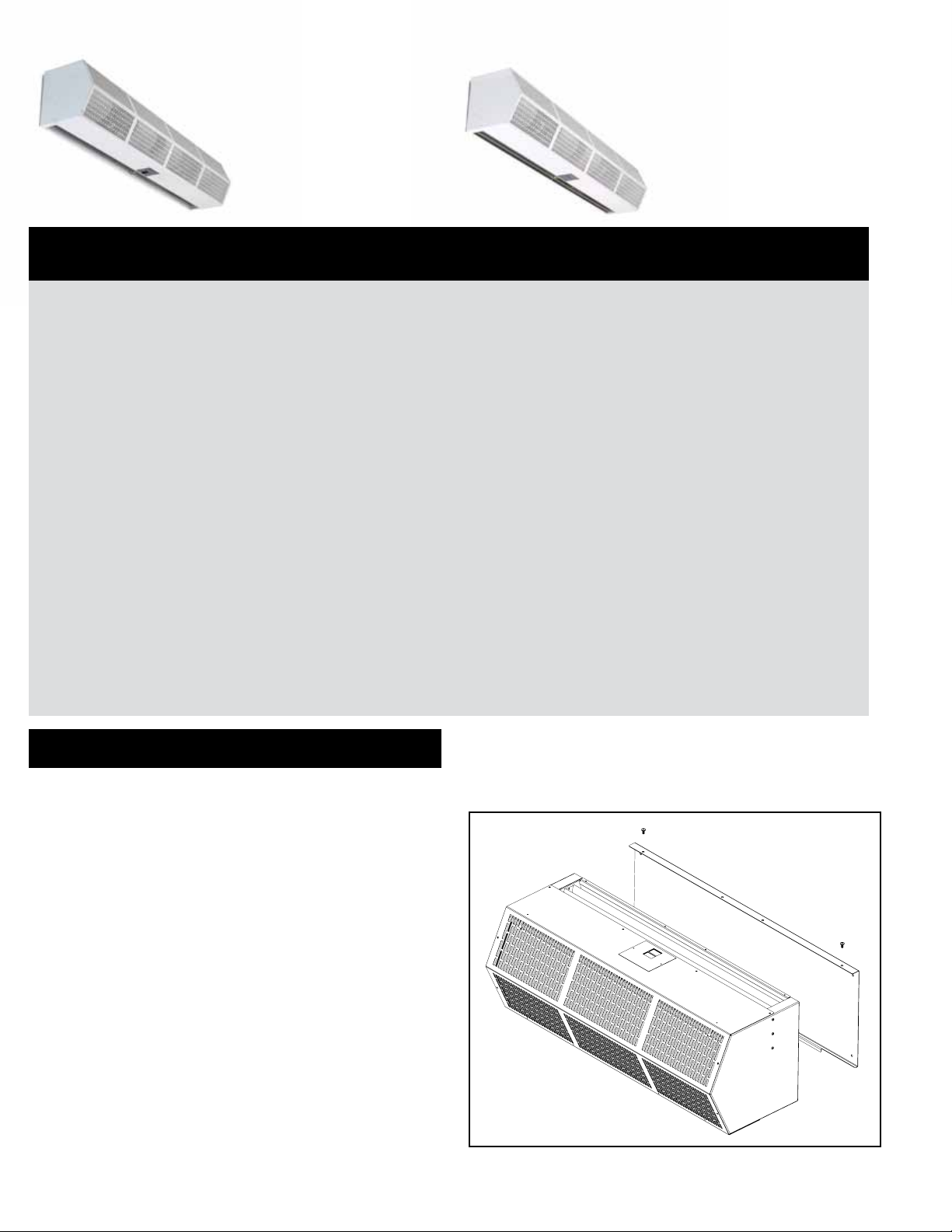
If the air curtain was ordered with a wall mounting plate,
remove and save the two (2) locking screws from the back
corners and detach the wall mounting plate. See Figure 1.
If the air curtain(s) were ordered with optional electrical accessories, the accessories will be found in the carton containing
the air curtain or in a separate carton(s) accompanying the air
curtain(s). Check all of the cartons/skids for accessories before
discarding.
Figure 1
2
Page 3
Simple to Install
Easy to operate & maintain
1
3
4" minimum
side clearance
from
combustible
material*
20˚
EXTERIOR
R
I
A
*Electrically Heated Units Only
For more information see page 4
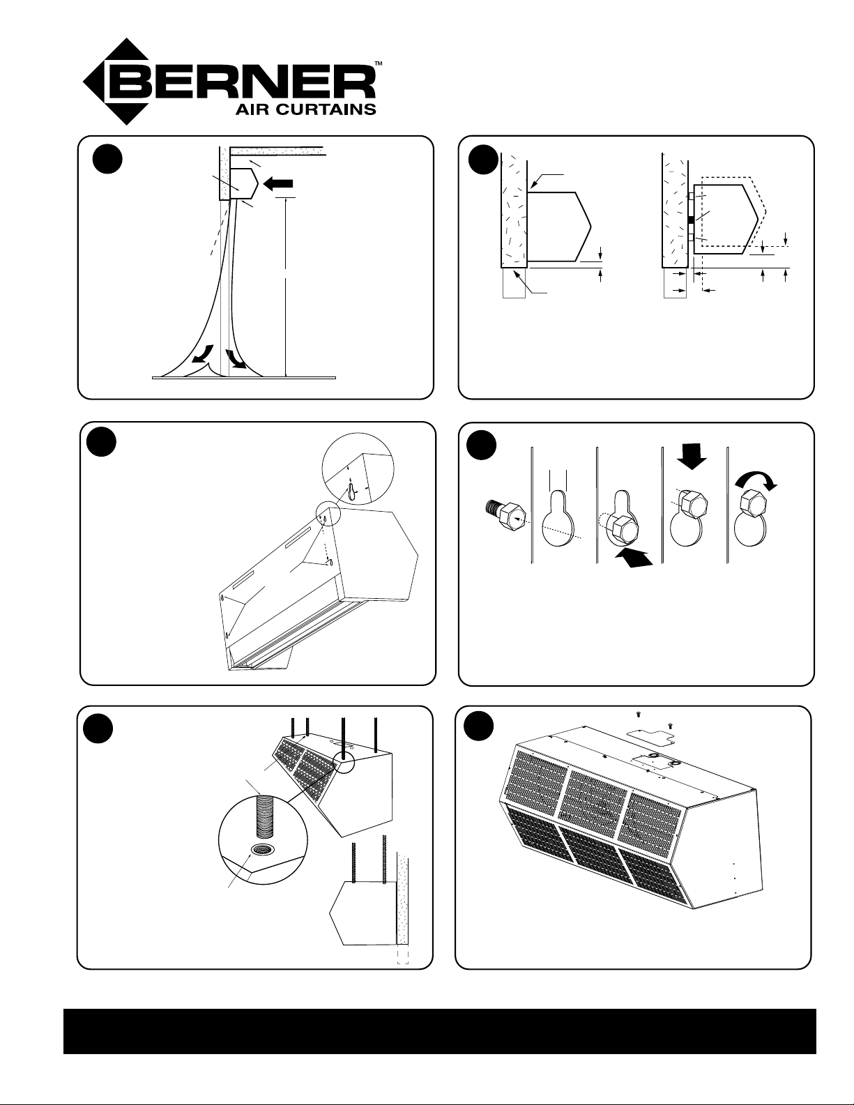
The keyhole slots are spaced 1” from
the ends, and 3/4” and 7” from the top.
Discharge
Nozzle
A
I
R
4" minimum*
6' minimum*
Mark the wall according to
the length of the air curtain.
If the keyhole slots are not
located where suitable
support is available,
drill new holes in
Keyhole
Mounting
Slots
the back plate
where space
is available.
For more information see page 5 For more information see page 5
AIR
Before hanging,
check to see what
the clearance is
above the door.
INTERIOR
3/4"
1"
7"
2
Flush Mounting
AIR
CURTAIN
Top of Doorway
Spacer
Seal
AIR
CURTAIN
1"
Spacer
3/8"
3/4"
3"
2"
Rule of thumb – If the unit must be mounted
higher than 1” above the opening, it must be
spaced out from the wall 3/8” for every inch the
unit is above the door opening.
For more information see page 4
4
1/4"
Line-up
Keyholes on
All Screws
Push
Backplate
Toward Wall
Slide
Backplate
Down
Tighten All
Screws
After installing the mounting hardware, lift and
slip the air curtain over the mounting hardware by
grasping the inlet rings. Tighten the mounting
hardware.
5
To use threaded
rod to hang from
the ceiling
instead of
the wall - use
the factory
installed
threaded inserts.
For more information see page 6 For more information see page 7
6
Suspension Rods
1/4” Threaded Insert
To wire – follow the wiring diagram (found inside
wiring compartment).
Side View
www.berner.com Berner International 800.245.4455
111 Progress Ave. / New Castle / PA / 16101 / USA
The controls ship in the same box as the air curtain.
3
Page 4
II. MOUNTING INSTRUCTIONS (General)
INDOOR MOUNTING - Environmental/ Insect/ Dust Control
OUTDOOR MOUNTING (Unheated Only) - Insect/Dust Control
4" minimum
side clearance
from combustible
material*
4" minimum*
AIR
The Commercial High Performance 10 & the Sanitation
Certied High Performance 7 Air Curtains are designed to be
an eective barrier against cold drafts in the winter and hot air
in the summer, ying insects and airborne contaminants.
To achieve optimum protection, the air curtain should be
mounted on the inside of the building, ush to the wall and
as close to the top of the door opening as possible. To ensure
peak performance, keep the air stream free of obstructions.
The air curtain will not perform properly if negative air
pressure exists in the building. Under these conditions,
a means for makeup air to the building must be provided
so that the air pressure on both sides of the opening is in
balance.
Before mounting the air curtain, check the supporting structure
to verify that it has sucient load-carrying capacity to support
the weight of the air curtain(s). The mounting hardware
(supplied by others) should be capable of supporting a
minimum of three (3) times the weight of the air curtain.
See Table 1 or Table 2.
IMPORTANT: A minimum of 4” is required above the top of the
air curtain for the installation and removal of the inlet
screen and access to electrical compartment.
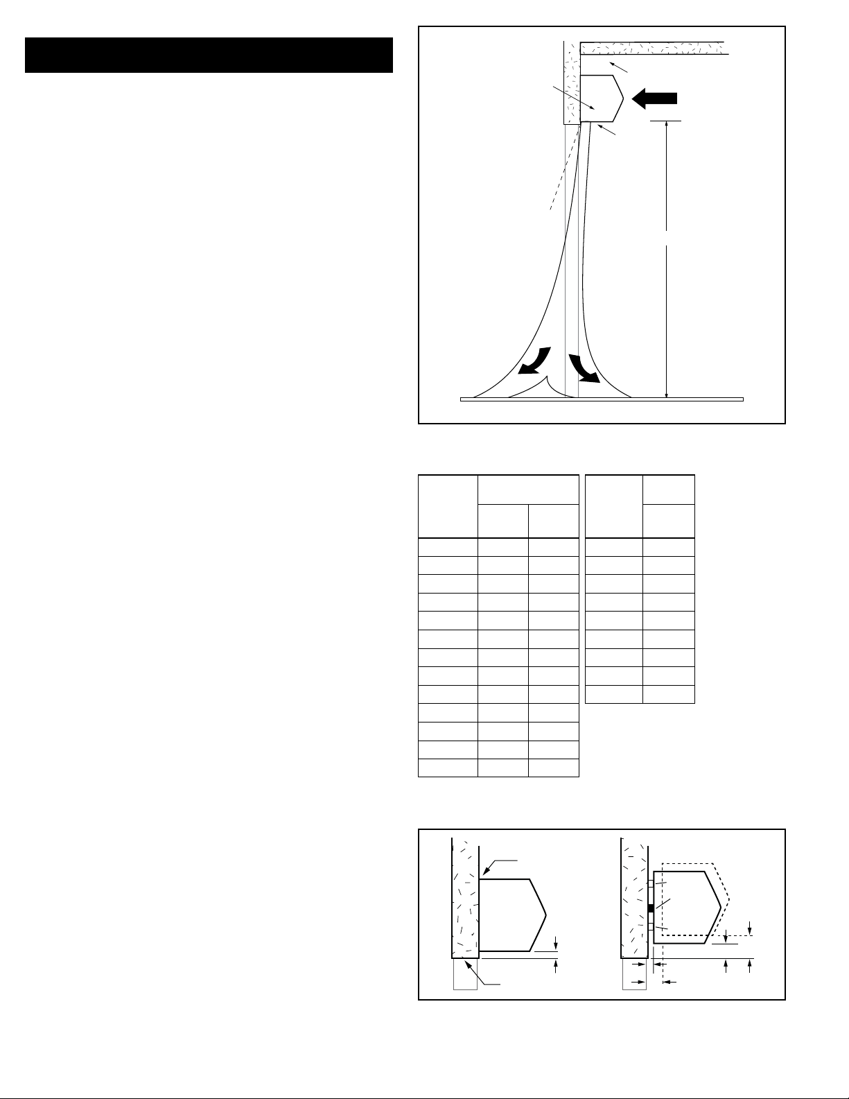
A. When determining the mounting location for the air
curtain(s), make sure that nothing interferes with the
curtain of air developed when the discharge vanes are
directed from 0° to 20° toward the door opening. If the
air stream strikes any obstruction (the top edge of the
doorway, a door opening device, etc.), the eectiveness
of the air curtain will be greatly reduced. See Figure 2.
B. For optimum performance, the bottom of the air curtain
(discharge nozzle) should be no more than 1” above the
top of the door opening with the air curtain(s) mounted
ush to the wall. If the air curtain must be mounted
higher, it must be spaced out from the wall 3/8” for
every inch the air curtain is above the door opening. See
Figure 3. For optimum protection, any void between the
air curtain and the wall should be sealed along the full
length of the air curtain.
C. Do not block (obstruct) the air intake grill. Insucient
airow can cause the unit to overheat.
D. Electric heated air curtain(s) shall:
1. Have a minimum clearance of at least 4” between
the sides and top of the air curtain and any
combustible material.
2. Have a minimum clearance of at least 6’ between
the bottom of the air curtain and the oor.
3. Be installed Indoors Only.
E. Proceed to either Section III - Wall Mounting or Section
IV - Suspended Mounting
Discharge
Nozzle
20˚
6' minimum*
EXTERIOR
A
R
I
I
A
R
*Electrically Heated Units Only
Figure 2
Net Weight
MODEL
CHD10-1036 50 52 SHD07-1036 50
CHD10-1042 52 55 SHD07-1042 52
CHD10-1048 53 56 SHD07-1048 53
CHD10-1060 54 63 SHD07-2060 70
CHD10-2060 70 96 SHD07-2072 84
CHD10-2072 84 104 SHD07-2084 104
CHD10-2084
CHD10-2096
CHD10-3096
CHD10-2108
CHD10-3108
CHD10-2120
CHD10-3120
CHD08
Ambient
CHD08
Electric
104 110 SHD07-2096 106
106 112 SHD07-3108 150
120 148 SHD07-3120 152
107 119
150 156
108 126
152
159
MODEL
TABLE 2 SHD07 Unit Weight
Weight
SHD07
Ambient
TABLE 1 - CHD10 Unit Weight
Flush Mounting
AIR
CURTAIN
1"
Top of Doorway
Figure 3
Net
Spacer
Seal
AIR
CURTAIN
Spacer
3/8"
3/4"
INTERIOR
3"
2"
4
Page 5
III. WALL MOUNTING
If a wall mounting plate was ordered with the air curtain,
proceed to B. Wall Mounting – using the wall mounting plate
(sold separately), otherwise proceed:
A. WALL MOUNTING - without wall mounting plate
1. Making sure that the air curtain is centered over the
opening, determine the exact mounting location of
the air curtain.
3/4"
1"
7"
NOTE: A minimum of 4” is recommended above the air
curtain to provide clearance for installation and removal of
the cover housing.
2. Remove the screen by removing screws from the
top, bottom and front of the air curtain, and slide the
screen away from the blower assembly.
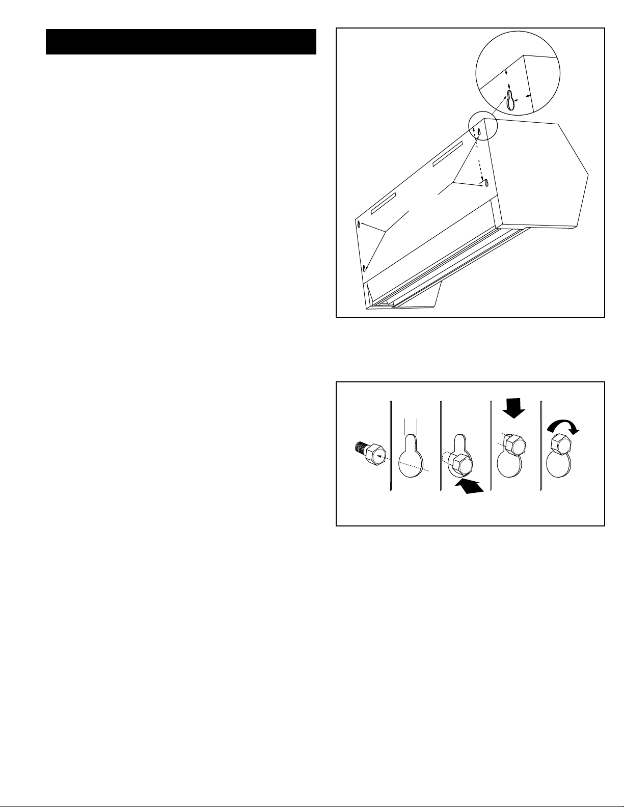
3. The air curtain is equipped with four 1⁄4” keyhole
mounting slots on the back of each unit for wall
mounting. The slots are spaced 1” from the ends, and
3/4” and 7” from the top. See Figure 4.
4. Mark the wall according to the length of the air
curtain. The wall must provide sucient support for
the air curtain. If the keyhole slots are not located
where suitable support is available, drill new holes in
the unit back plate where space is available.
5. The mounting hardware (supplied by others) must be
capable of supporting a minimum of three times the
net weight of the air curtain. See Weight Chart, Table
1 or Table 2.
6. Keyhole Mounting: Install the mounting hardware
(supplied by others), allowing for space to hang the
air curtain by not fully tightening. Without touching
the blower wheels, lift and slip the air curtain over the
mounting hardware by grasping the inlet rings of the
blower housing. Tighten the mounting hardware. See
Figure 5.
Keyhole
Mounting
Slots
1/4"
Line-up
Keyholes on
All Screws
Figure 4
Push
Backplate
Toward Wall
Figure 5
Tighten All
Screws
Slide
Backplate
Down
7. Drilled Mounting Holes: Lift the air curtain by
grasping the inlet rings on the blower housing,
without touching the blower wheels, and install the
mounting hardware (supplied by others) through the
drilled holes.
8. Reinstall the screen using hardware removed in Step 2.
9. Proceed to Section V - Electrical Connections.
5
Page 6
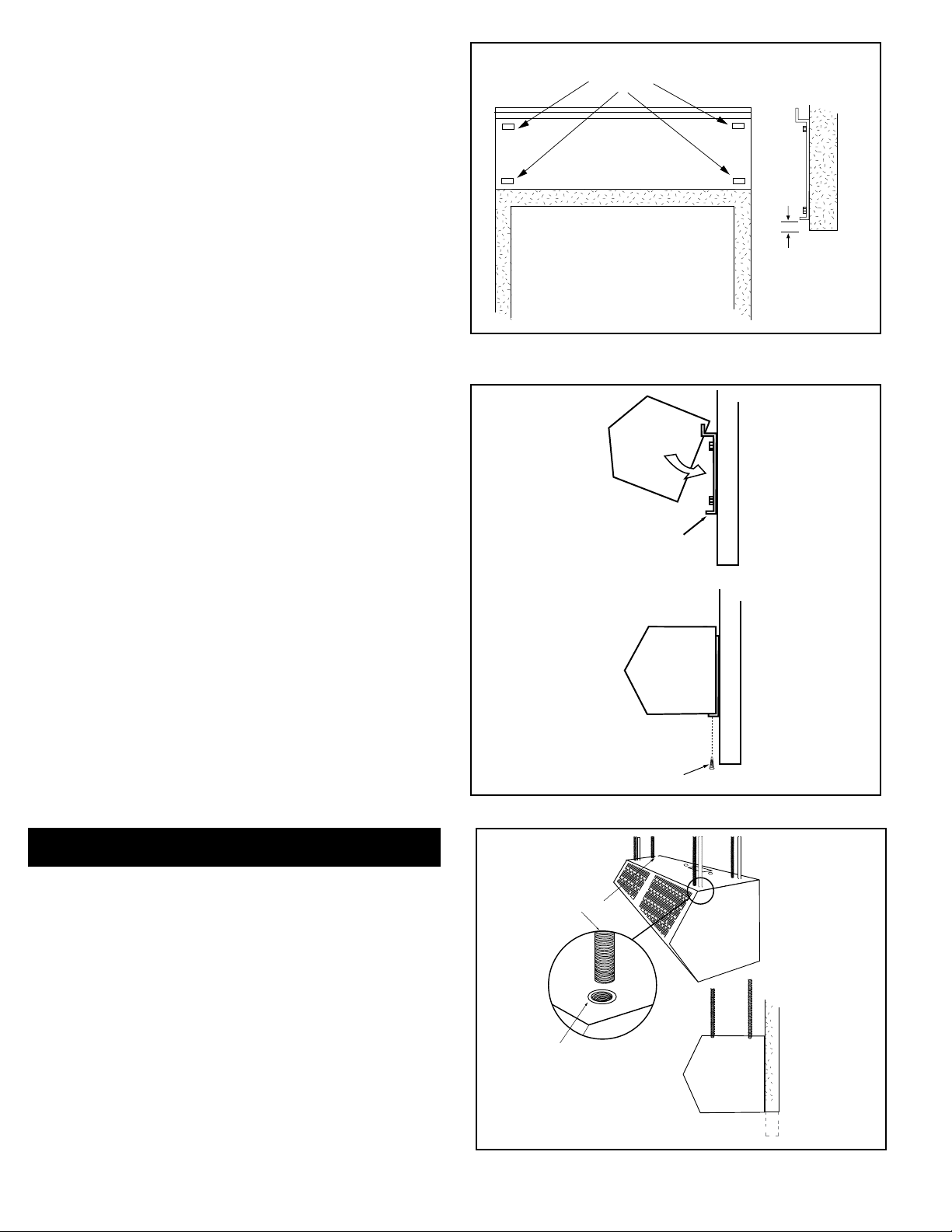
B. WALL MOUNTING – using the wall mounting plate
(sold separately)
1. PREPARATION
a. Position and center the mounting plate over
the door opening. The mounting plate must
be positioned with the “Z” lip on top. Drill
mounting holes on the mounting plate. See
Figure 6.
b. Mark the wall in the center of each mounting
plate hole. The wall must provide sucient
support for the air curtain. The mounting
hardware (supplied by others) must be
capable of supporting a minimum of three
times the net weight of the air curtain. See
Weight Chart, Table 1 or Table 2. If the
location of the marks on the wall do not
provide suitable support, mark and drill
additional holes.
c. Drill the four holes as marked on the wall and
attach the mounting plate with anchors (if
used) and the four mounting screws (provided
by others).
2. ATTACHING THE AIR CURTAIN
TO THE MOUNTING PLATE
a. Raise the air curtain over the door (air
discharge nozzle facing down) and on to the
mounting plate. First, tilt the unit upward
matching the rectangular openings to the “Z”
lip on the mounting plate. See Figure 7.
b. Lower the air curtain into place, allowing it to
rest on the lower lip of the mounting plate.
c. After the air curtain is securely attached to the
mounting plate, re-install the two (2) locking
screws at the bottom corners. See Figure 7.
Recommended Mounting
Plate Holes
Doorway Opening
1" max.
Doorway
Opening
FIGURE 6 - Positioning of Mounting Plate
Mounting Plate
Lower Lip
IV. SUSPENDED MOUNTING
A. For top mounting using suspension rods, four (4) factory
installed 1/4” threaded inserts are located in the top of the
air curtain. See Figure 8.
B. Install 1/4” threaded rods, or other suitable hardware at
a location with sucient support for the air curtain. The
mounting hardware (supplied by others) must be capable
of supporting a minimum of three times the net weight of
the air curtain. See Weight Chart, Table 1 or Table 2.
C. Attach threaded rods, or other suitable hardware to the top
mounted threaded inserts.
D. Proceed to Section V – Electrical Connections
Locking Screws
FIGURE 7
Suspension Rods
1/4” Threaded Insert
Side View
FIGURE 8 - Suspended Mounting
6
Page 7
V. ELECTRICAL CONNECTIONS
All electrical wiring and connections MUST be performed by
qualied personnel in accordance with the latest edition of the
National Electrical Code ANSI/NFPA No. 70 or, in Canada, the
Canadian Electrical Code, Part 1-C.S.A. Standard C22.1 and local
codes and regulations.
MAKE SURE THE CORRECT
VOLTAGE AS MARKED ON THE UNIT IS USED.
A. A separate line voltage supply with a suitable branch
circuit protection device should be run directly from the
main electrical panel to the unit. A disconnect switch for
each branch circuit is a required part of this installation.
See the voltage label on the unit for circuiting and total
electrical load. The wiring diagram is located in the
wiring compartment.
B. All eld wiring must be copper with a minimum
insulation of 60°C within approved conduit. If any of the
wire supplied with the unit must be replaced, it must be
replaced with copper wiring with a minimum insulation
of 90°C.
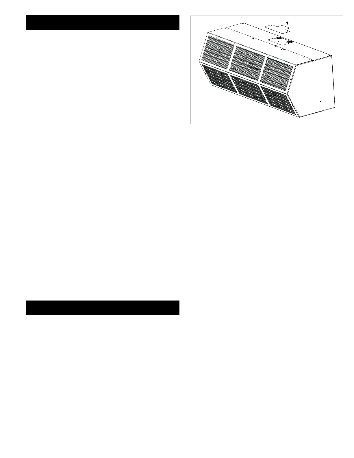
C. Remove the wiring compartment cover on top of the air
curtain. See Figure 9.
D. The top of the air curtain has knockouts on each side of
the wiring compartment. Remove the required knockout
and connect the power supply to the air curtain. Connect
all supply and control circuit wires according to the
wiring diagram provided.
NOTE: For Electrically heated air curtains provided with
the optional remote thermostat, mount and wire the
thermostat according to thermostat instructions and
wiring diagram.
FIGURE 9
For Electrically heated air curtains proceed to Section
V - Field Connections, otherwise proceed to Section VI Airow Adjustments
VI. FIELD CONNECTIONS
A. ELECTRICALLY HEATED MODELS
The heater circuit may be controlled by a remote thermostat,
manually through a unit mounted or remote mounted three
position - fan only/o/fan with heat switch. Overheating
protection is provided by auto reset thermal cutouts built
into the blower assembly (see wiring diagram). Proceed to
Section VII - Operating Instructions.
7
Page 8
VII. OPERATING INSTRUCTIONS
A. GENERAL OPERATION
Air curtain operation may be divided into four areas: control
package, fan activation, fan speed selection, and heat
activation. Depending on the type of controls ordered one
or more of the following may be applicable. The air curtain
must be properly installed before it is used.
1. Control packages control the air curtain’s sequence of
operation. Unit modes/control packages are built into
the unit and may not be changed in the eld.
Refer to your wiring diagram for specics about activation
connections and sequence of operation.
a. Basic Control Package – The unit is activated by
a door or selector switch. Either switch may be line
voltage or low voltage (24V).
b. Deluxe Control Package – The unit is activated
by a door or selector switch, but has a factory installed
time delay allowing the unit to keep running for a
period of time after the door closes.
c. Comfort Plus Control Package – Available only on
heated units, the unit is activated by a door or
selector switch AND a thermostat to provide
supplemental heating. NOTE: Not available with 575V
motors.
2. Unheated air curtains will have the fans activated by a
door or selector switch or sensor. The unit may be single
speed and require no fan speed selector (On/O), or may
have three fan speeds which require either a unit or
remote mounted switch (O, High, Med, Low).
AIR
INTERIOREXTERIOR
A
R
I
I
A
R
12"
AIR
INTERIOREXTERIOR
R
I
A
A
I
R
FIGURE 10
3. Heated air curtains will have fans activated by a door or
selector switch or sensor, but may also be activated by
the thermostat in Comfort Plus Mode. The unit has
three fan speeds which can be set by either a unit or
remote mounted switch (Low, Med, High, O, Low heat,
Med Heat, High Heat).
4. Heat activation is controlled by either a unit or remote
mounted thermostat, and a unit or remote mounted
switch.
B. AIR STREAM ADJUSTMENT
1. With the air curtain operating and the door in its full open
position, check to see that nothing is obstructing the
airow at the discharge nozzle vanes.
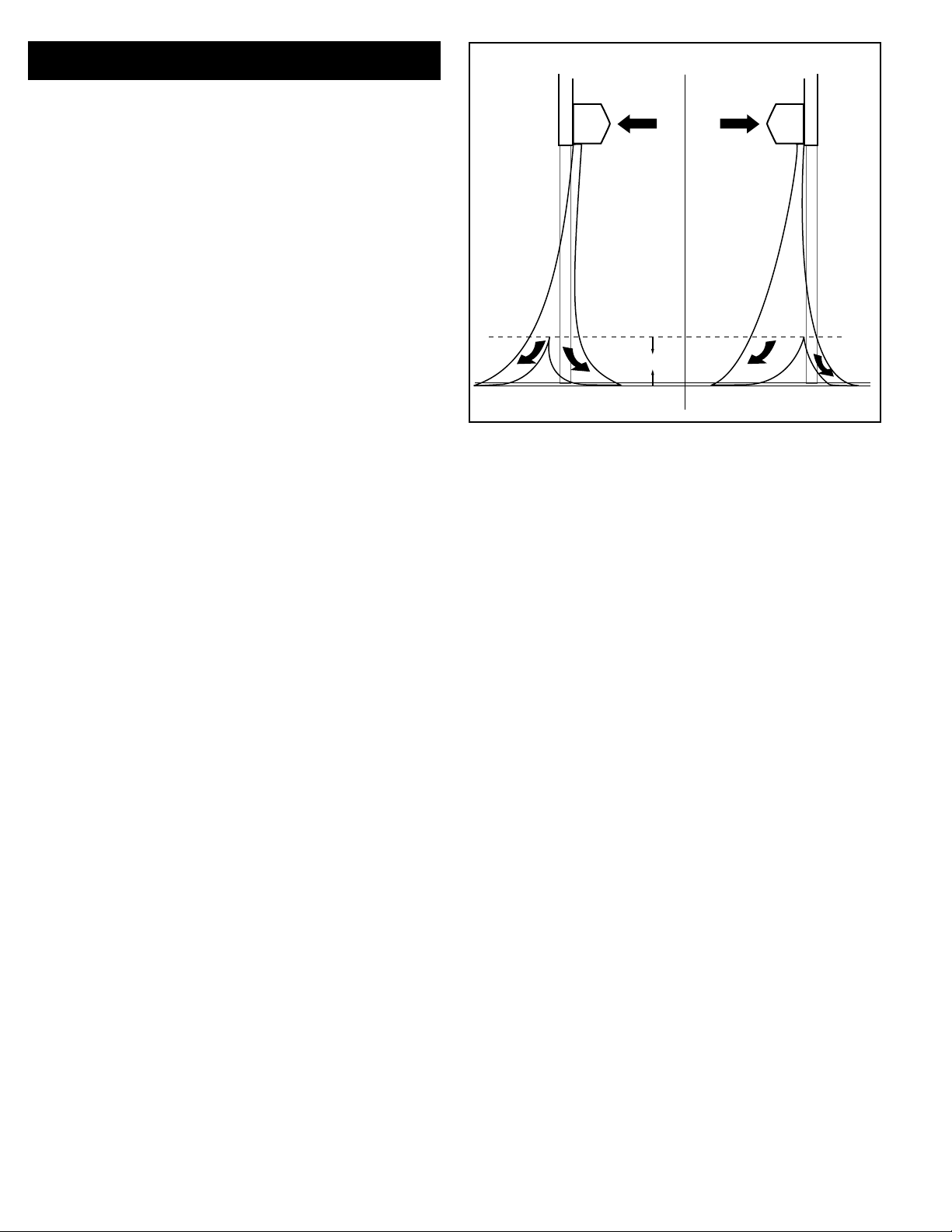
2. Find the air stream split location. Hold a handkerchief
by its corners, approximately 12” above the oor. Gently
move the handkerchief back and forth in the doorway.
Make sure the air is being directed to both the inside
and the outside. See Figure 10. The split location is
indicated where the handkerchief is vertical with minimal
or no uttering.
3. The split location should be approximately 3” outside the
doorway. If necessary adjust the discharge nozzle vanes
by de-energizing the unit, loosening the nozzle vane
locking screws and adjusting vanes.
8
Page 9
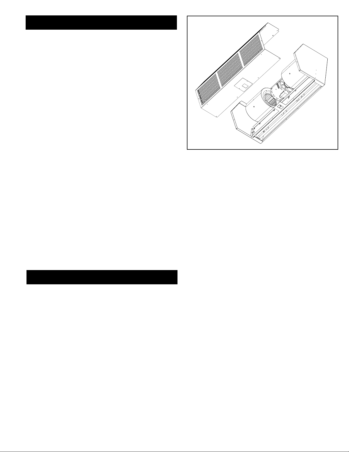
VIII. MAINTENANCE & CLEANING
CAUTION: ELECTRIC SHOCK HAZARD Disconnect power
whenever servicing unit. More than one disconnect may be
required to de-energize unit.
Keep your air curtain operating at peak eciency by cleaning
the blower wheels, motor(s) and intake grill. Buildup of dust on
the blower wheels can cause vibration, noise and excessive wear
on the motor bearings. The frequency of cleaning will depend
on the environment where the unit is operating.
Dirty, dusty or greasy environments could require a cleaning
schedule of once every two months. If the environment is not
that dirty, the unit(s) should be scheduled for cleaning a minimum of once every (6) months.
A. PERFORMING PREVENTIVE MAINTENANCE
1. Disconnect and lockout power to the unit.
2. Remove the intake screen by removing the machine
screws located around the bottom, front and top of the
screen See Figure 11.
3. Vacuum and scrape (if necessary) to
remove the build-up of dirt and debris. The motor(s)
are permanently lubricated and require no additional
lubrication. Re-install the cover and intake grill.
4. Switch the power on af ter cleaning.
FIGURE 11
CAUTION: STAND CLEAR OF THE UNIT OR WEAR
SAFETY GOGGLES AS LOOSE DEBRIS MAY BE
PRESENT AND MAY EXIT THE NOZZLE.
IX. SERVICE
Any service performed on the air curtain MUST be done by
qualied personnel.
Berner air curtains require very little servicing. All parts are
easily accessible for periodic inspection and maintenance.
Units should be cleaned at least twice a year. Your particular
application (the amount of dirt and dust in the air) and
location of the unit(s) will determine how often your
unit(s) will need to be cleaned and serviced. All motors have
permanently lubricated, sealed, sleeve bearings and require no
maintenance.
9
Page 10
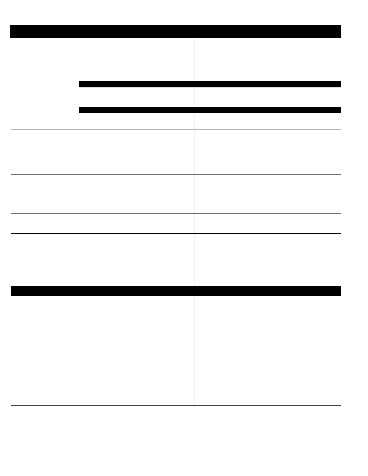
X. TROUBLESHOOTING
SYMPTOMS CAUSE REMEDY
NO AIR • Electrical Power supply line open (no power) • Check power source, check method of control in
ON position
• Fuse blown/circuit breaker tripped • Replace fuse(s)/reset breaker
• Motor overload tripped • Internally protected motor - should reset
• Failed switch • Replace switch
MOTOR RUNNING/FANS ARE NOT ROTATING
• Broken or fan hub • Replace fan
• Shaft rotating inside fan • Tighten set screws/tighten fan on shaft
• Broken/Loose coupling • Replace/Tighten coupling
ELECTRICAL CONTROLS NOT FUNCTIONING WHEN DOOR IS OPEN
• Selector switch is in o position • Turn switch to “ON” position
• Door limit switch not operating • Repair or replace limit switch
MINIMUM • Air directional discharge vanes misadjusted • Adjust vanes to proper position, see instructions
• Inadequate intake clearance • Move air curtain or remove obstruction
Provide adequate space for air curtain
• Blower motor operates below speed • Improve voltage
• Fan rubbing against housing • Free fan from housing
• Fan wheels clogged with dirt • Clean and vacuum fan wheels
• Air stream too weak •
AIR IS NOT
HITTING
see installation instructions
FLOOR
• Air stream hits obstruction • Remove obstruction or reposition air curtain
(move out
• Negative pressure • Relieve negative pressure by providing make-up air
• Shaft rotating inside fan • Tighten set screws/Replace fan
UNEVEN AIR
• One motor not operating • Repair or replace motor/Check electrical connections
• Nozzle not angled out far enough • Adjust nozzle angle to outside
EXCESSIVE AIR
• Air movement too cold • Add auxiliary heat to overcome wind chill
MOVEMENT AT
• Pushing air outside building • Adjust discharge angle back into building
DOORWAY
SEE AIR IS NOT HITTING FLOOR SYMPTOMS
automatically after cool-down, if not replace motor.
Adjust nozzle to proper position, adjust motor speed;
3
/8” for every 1” up from the door)
ELECTRICALLY HEATED MODELS
NO HEAT • Switch turned to “OFF” position • Turn switch on
• Thermostat not set properly • Change thermostat setting
• Coils burned out due to lack of air • Correct airow problem; replace coils
• Automatic reset thermal cutout failed in open position • Replace automatic thermal cutout
• Manual reset thermal cutout tripped • Reset manual thermal cutout
• Defective switch • Replace switch
NOT ENOUGH • Thermostat in wrong location - thermostat too • Move thermostat away from air stream
HEAT close to discharge
• Improper voltage • Supply proper voltage
• Thermostat not set properly • Change temperature setting
TOO MUCH • Thermostat in wrong location • Move thermostat closer to air stream
HEAT • Thermostat not set properly • Change temperature setting
• Insucient air over coil • Remove restriction on intake
• Improper voltage • Supply proper voltage
10
Page 11

11
Page 12
XI. WARRANTY
Berner International (“The Company”) warrants all new equipment to be free of defects in workmanship and material for a period
of ve years (5 years) on unheated models and two years (2 years) on heated models from the original date of shipment, provided
the equipment has been properly cared for, installed and operated in accordance with the limits specied on the nameplate and The
Company’s instructions.
The Company will correct by repair or replacement, at its option and expense, any proven defects in said apparatus, subject to the above
conditions, provided that immediate written notice of such defects is given to The Company. The warranty does not include any labor
incurred for the removal or installation of defective part(s). The Company reserves the right to inspect, or have inspected by a qualied
representative, any apparatus at the place of installation before authorizing repair or replacement. Repair or replacement will be made
F.O.B. factory with any applicable transportation charges to be borne by the customer. Merchandise not of The Company’s manufacture
supplied in piece, or in component assemblies, is not covered by the above warranty, but The Company will give the customer the benet
of any adjustment as made with the Manufacturer.
This warranty is void if the apparatus has been tampered with in any way or shows evidence of misuse.
The Company will not assume any expense or liability for repairs made outside its factory without proper written consent from its service
manager, nor for any transportation charges on apparatus returned to the factory without written authorization by The Company.
Nothing in the above warranty provisions, however, shall impose any liability or obligation of any type, nature or description upon Berner
International if Berner has not received payment in full for the apparatus in question.
THERE ARE NO WARRANTIES WHICH EXTEND BEYOND THE DESCRIPTION ON THE FACE HERE OF INCLUDING
THE IMPLIED WARRANTY OF MERCHANTABILITY AND FITNESS FOR A PARTICULAR PURPOSE.
LIMITATION OF DAMAGES
Notwithstanding anything to the contrary above, customer’s exclusive remedy for any and all losses or damages resulting
from the sale of The Company’s equipment under this agreement, including but not limited to, any allegations of breach of
warranty, breach of contract, negligence or strict liability, shall be limited, at The Company’s option, to either the return of
the purchase price or the replacement of the particular equipment for which a claim is made and proved. In no event shall The
Company be liable for any special, consequential, incidental or indirect losses or damages from the sale of The Company’s
equipment under this agreement.
SERIAL NUMBER MODEL NUMBER DATE PURCHASED
Saving energy and creating healthy, comfortable environments
BERNER INTERNATIONAL
New Castle, Pennsylvania
724-658-3551 • 1-800-245-4455 • www.Berner.com
Berner reserves the right to alter specifications without prior notice.
© Copyright 2017 Berner International MADE IN U.S.A.
12
 Loading...