

Berner ARA1060, ARA1048, ARA1042 Installation & Maintenance Instructions Manual
READ AND SAVEREAD AND SAVE
READ AND SAVE
READ AND SAVEREAD AND SAVE
THESE INSTRUCTIONSTHESE INSTRUCTIONS
THESE INSTRUCTIONS
THESE INSTRUCTIONSTHESE INSTRUCTIONS
No.: II-500
Date: January, 2011
Installation &
Maintenance Instructions
WARNING: TO REDUCE THE RISK OF FIRE, ELECTRIC SHOCK, OR INJURY TO PERSONS, OBSERVE THE
FOLLOWING:
A. Use this unit only in the manner intended by the manufacturer. If you have any questions, contact the manufacturer.
B. Before servicing or cleaning unit, switch power off at service panel and lock the service disconnecting means to prevent
power from being switched on accidentally. When the service disconnecting means cannot be locked, securely fasten a
prominent warning device, such as a tag, to the service panel.
C. Installation work and electrical wiring must be done by qualified person(s) in accordance with all applicable codes and
standards, including fire-rated construction.
D. Sufficient air is needed for proper combustion and exhausting of gases through the flue (chimney) of fuel burning equipment
to prevent back drafting. Follow the heating equipment manufacturer’s guideline and safety standards such as those
published by the National Fire Protection Association (NFPA), and the American Society for Heating, Refrigeration and Air
Conditioning Engineers (ASHRAE), and local code authorities.
E. When cutting or drilling into wall or ceiling, do not damage electrical wiring and other hidden utilities.
WARNING FOR FUEL BURNING EQUIPMENT:
Sufficient air is needed for proper combustion and exhausting of gases through the flue (chimney) of fuel burning equipment to
prevent back drafting. Follow the heating equipment manufacturer’s guideline and safety standards such as those published by
the National Fire Protection Association (NFPA), and American Society for Heating, Refrigeration and Air Conditioning
Engineers (ASHRAE), and local code authorities.
UNCRATING
This unit was quality inspected and tested immediately prior to packaging and was in operating condition at that time. Check the
shipping carton and unit for any damage that may have occurred during shipment. If damage is found, notify the shipping company
immediately.
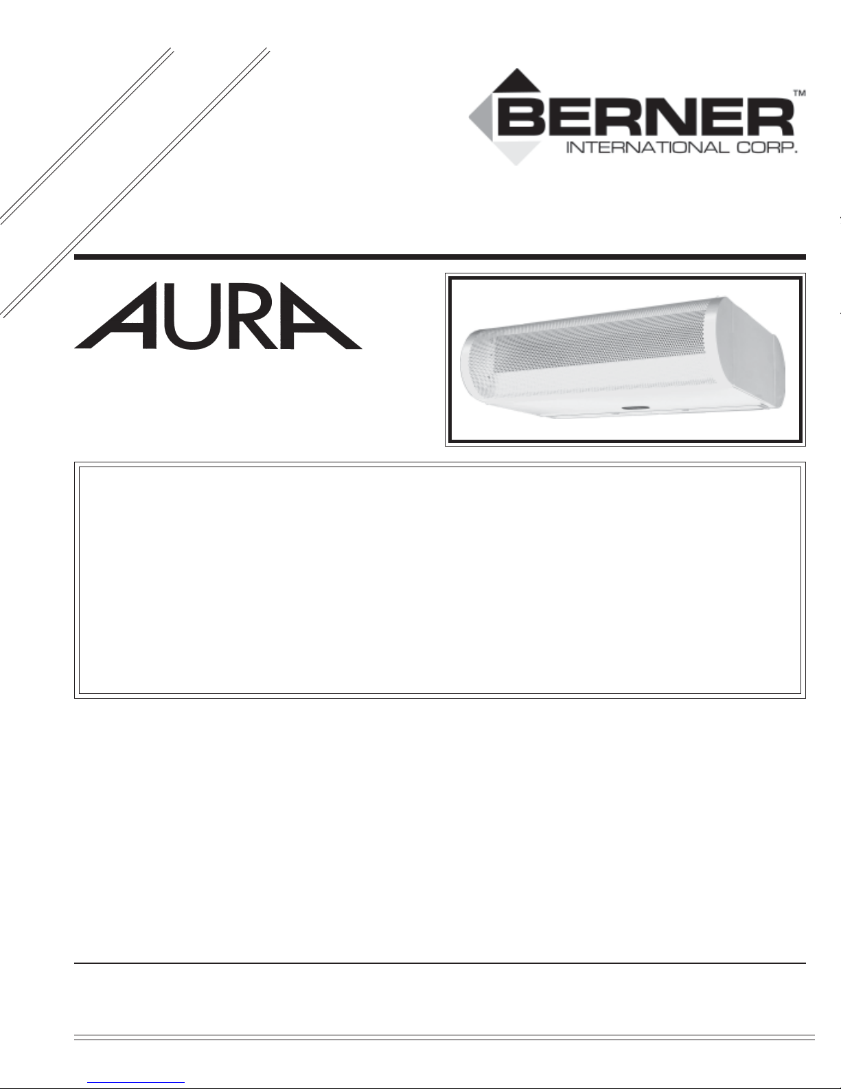
The AURA Series air door is shipped completely assembled. Remove the accessory box and the louvered discharge grille (wrapped in
protective paper) from the carton. Remove the AURA Series air door from the carton. See Figure 1. Immediately upon unpacking the
unit, verify that the rating nameplate agrees with the electric supply available.
Do NOT attach the louvered discharge grille or perforated intake grille at this time.
BERNER INTERNATIONAL CORPORATION
724-658-3551 • 1-800-245-4455 • www.berner.com • airdoors@berner.com
© Copyright 2011 Berner International Corporation
New Castle, Pennsylvania
MODEL
ARA1036 120 130
ARA1042 135 145
ARA1048 158 168
ARA1060 185 195
C .For optimum performance, the bottom of the unit (discharge
grille) should be a maximum of 1” above the top of the door
opening with the unit mounted flush to the wall. If the unit
must be mounted higher, it must be spaced out from the wall
3
/8” for every inch the unit is above the door opening (maximum recommended mounting height of 8’). Where possible
(installation site permitting), for optimum protection, any void
between the air door and the wall should be sealed along the
full length of the unit.
D. Do not block (obstruct) the air intake grille. Insufficient air
flow can cause the unit to overheat.
Net Weight
Ambient (lbs)
TABLE 1 - Unit Weight
Net Weight
Heated (lbs)
FIGURE 1 - Contents
Each AURA Series carton contains the following pre-assembled
components:
✓ (1) AURA air door unit
✓ (1) Louvered discharge grille
✓ (1) Perforated intake grille
✓ (2) Plastic snap ring bushings
✓ (6) No. 6 x ¾ Phillips head screws
✓ (1) Remote selector switch
Optional Accessories
✓ Wall mounting plate
✓ Perforated back adapter
✓ Solid back adapter
✓ Solid back adapter (with or without lights)
I. MOUNTING INSTRUCTIONS
(All Models)
E. Electric heated units should have:
1. A minimum clearance of at least 4” between the sides and
top of the unit and any combustible material.
2. A minimum clearance of at least 6’ between the bottom of
the unit and the floor.
Proceed to either Suspended or Wall Mounting Instruc-
tions.
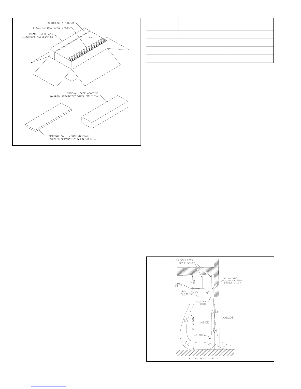
II. SUSPENDED MOUNTING
A. NO BACK ADAPTOR: Figure 2
1. Suspend the AURA Series air door on the inside of the
building with the louvered discharge grille facing the door
opening. See Figure 2.
2. Mount and level the air door by connecting four (4) 5/16 -18
threaded rods or other suitable hardware (supplied by others) to the (4) 5/16-18 threaded inserts located on top of the
unit.
A. Before mounting the unit, check the supporting structure to
verify that it has sufficient load-carrying capacity to support
the weight of the unit(s). The mounting hardware (supplied
by others) should be capable of supporting a minimum of three
(3) times the weight of the unit. See Table 1.
B. Nothing should interfere with the curtain of air developed when
the discharge grille vanes are directed 20° toward the door
opening. If the air stream strikes any obstruction (the top
edge of the doorway, a door opening device, etc.), the effectiveness of the unit will be greatly reduced.
FIGURE 2 - Suspension Mount without Back Adapter
- 2 -
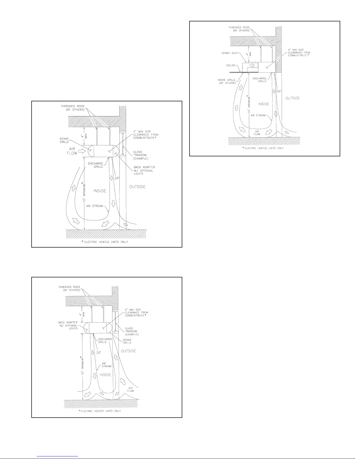
B. WITH BACK ADAPTER: Figures 3 & 4
1. The unit may be mounted with the louvered discharge
grille facing toward the door opening, or the interior of
the building (electric heated models only). See Figures
3 and 4.
2. Figure 3 installation (louvered discharge grille facing interior of the building). Follow instructions A & B above.
3. Figure 4 installation (louvered discharge grille facing interior of the building). A maximum of 6” between the
wall and intake grille is required. Install the back adap
tor at this time. Follow instructions 2 under Item A.
FIGURE 5 - In-Ceiling Suspension Mount Without Adapter
C. ABOVE CEILING: Figure 5
Follow instructions 1 & 2 under Item A. See Figure 5. The
bottom of the unit can be exposed for easy servicing.
FIGURE 3 - Suspension Mount with Back Adapter
FIGURE 4 - Suspension With Back Adapter Reverse Flow
D. DO NOT install the perforated intake grille or the lou-
vered air discharge grille at this time. Proceed to Section
IV ELECTRICAL CONNECTIONS.
III. WALL MOUNTING
(Optional Wall Mounting Bracket Required)
See Figures 6-10
A. When the AURA Sseries air door is for wall mounting, four
5/16” shoulder bolts will be pre-assembled on the back of the
unit (opposite the perforated intake grille).
B. The wall mounting plate is designed to fit flush with the back
of the entire AURA door.
C. Determine the exact location of the air door unit. Position the
center of the wall mounting plate over the center of the door
opening with the larger opening of the key hole slots facing
up.
For optimum performance, the bottom of the mounting plate
should be no more than 1” above the top of the door opening.
STANDARD WALL MOUNTING: Figure 7A. The wall
mounting plate thickness provides a natural 1
allows for mounting up to 4” above the opening.
HIGH WALL MOUNTING: If the wall mounting plate must
be mounted higher than 4” above the door opening, it must be
spaced out from the wall 3/8” for every inch the unit is above
the door opening. See Figure 7B.
For optimum performance, do not exceed the recommended
maximum mounting height of 8’ above the finished floor. For
optimum protection, any void between the mounting plate and
the wall should be sealed along the full length of the mounting
plate.
- 3 -
3
/8” space which
 Loading...