

Berner AHC10-1048, AHC10-1042, AHC10-2048, AHC10-2060, AHC10-2072 Important Instructions Manual
...
IMPORTANT INSTRUCTIONS
Saving energy and creating healthy, comfortable environments
READ AND SAVE
THESE INSTRUCTIONS
No. II-260
Date May, 2014
ARCHITECTURAL
High Performance 10
AIR CURTAIN SERIES AHC10
Installation & Maintenance Instructions
TABLE OF CONTENTS
I. UNCRATING............................................................................................................................................................ ...................................... 2
II. WALL MOUNTING - INDOOR INSTALLATION ........................................................................................................................................ 2
III. WALL PREPARATION ....................................................................................................................................... .........................................3
IV. ATTACHING THE AIR CURTAIN TO THE MOUNTING PLATE.......................... ...................................................................................... 3
V. TOP MOUNTING - INDOOR INSTALLATION............................................................................................................................................4
VI. ELECTRICAL CONNECTIONS ..................................................................................................................................................................4
VII. ELECTRICALLY HEATED MODELS .................................... ....................................................................................................................4
VIII. STEAM OR HOT WATER HEATED MODELS .........................................................................................................................................5
IX. OPERATING INSTRUCTIONS ...................................................................................................................................................................5
X MAINTENANCE AND CLEANING...............................................................................................................................................................6
XI. SERVICE ............................................................................................................................................................... ......................................4
XII.WARRANTY ................................................................................................................................................ ...............................................8
TROUBLESHOOTING ................................................................................................................................................ .....................................7
WARNING: TO REDUCE THE RISK OF FIRE, ELECTRIC SHOCK OR INJURY TO PERSONS, OBSERVE THE FOLLOWING:
A. Read all instructions before installing or using this air curtain.
B. Use this unit only in the manner intended by the manufacturer and described in this manual. Any other use not recommended by the
manufacturer may cause re, electric shock, or injury to persons. If you have any questions, contact the manufacturer.
C. Before servicing or cleaning unit, switch power o at service panel and lock the service disconnecting means to prevent power from
being switched on accidentally. When the service disconnecting means cannot be locked, securely fasten a prominent warning device,
such as a tag, to the service panel.
D. Installation work and electrical wiring must be done by qualied person(s) in accordance with all applicable national and local codes
having jurisdiction, including re-rated construction. See page 4, ELECTRICAL CONNECTIONS (NEC Code ANSI/NFPA No. 70).
E. When cutting or drilling into wall or ceiling, do not damage electrical wiring and other hidden utilities.
F. To reduce the risk of re, do not store or use gasoline or other ammable vapors and liquids in the vicinity of the air curtain.
G. This air curtain is hot when in use. To avoid burns, do not let bare skin touch hot surfaces. Keep combustible materials, such as furniture,
pillows, bedding, papers, clothes, etc. and curtains at least 1 inch from the top, back, front, sides and at least 6 feet from the discharge
of the air curtain.
H. Extreme caution is necessary when any air curtain is used by or near children or invalids, and whenever the heater is left operating
unattended.
I. Do not operate any air curtain after it malfunctions. Disconnect power at the service panel and have the air curtain inspected by a
reputable electrician before reusing.
J. To disconnect the air curtain, turn controls to "o", and turn o power to the air curtain circuit at main disconnect panel.
K. Do not insert or allow foreign objects to enter any ventilation or discharge opening as this may cause an electric shock or re, or
damage the air curtain.
L. To prevent a possible re, do not block the air intake or discharge of the air curtain in any manner.
M. The air curtain has hot and arcing or sparking parts inside. Do not use it in areas where gasoline, paint, or ammable vapors or liquids
are used or stored.
N. This heater may include an audible or visual alarm to warn that parts of the heater are getting excessively hot. If the alarm sounds
(or illuminates), immediately turn the heater o and inspect for any objects on or adjacent to the heater that may have blocked the airow
or otherwise caused high temperatures to have occurred. DO NOT OPERATE THE HEATER WITH THE ALARM SOUNDING (OR ILLUMINATING).
-1-
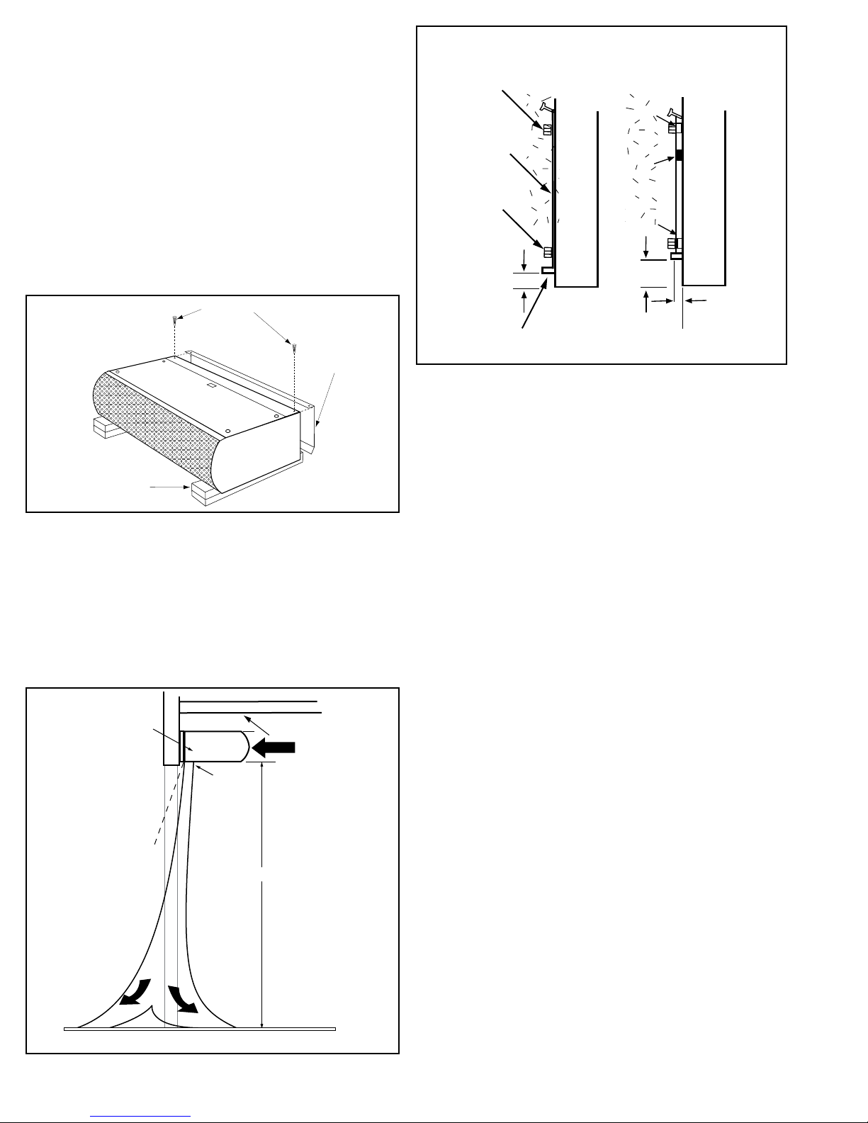
I. UNCRATING
Carefully examine the carton(s) for damage before opening. If
the carton is damaged, immediately notify the shipping company. Open the carton and remove all protective packing. Remove the unit by lifting vertically. Place the unit upside down
on end supports to avoid damage to the electrical junction
box. If the unit will be wall mounted, remove and save the two
(2) locking screws from the back corners and detach the wall
mounting plate. See Figure 1
Mounting
Screws
Mounting
Plate
FLUSH WALL
MOUNT
Spacer
EXTENDED
WALL MOUNT
Seal
ACCESSORIES: If the unit(s) were ordered with optional electrical accessories (door switch, control panel, etc.), the accessories may be found in
the carton containing the unit or in a separate carton(s) accompanying
the unit(s). Check all of the cartons/skids for accessories before discarding.
Locking Screws
Bottom of Unit
Packaging
Figure 1
Wall
Mounting
Plate
The ARCHITECTURAL HIGH PERFORMANCE 10 Air curtain is
designed to be an eective barrier against cold drafts in the
winter and hot air in the summer, ying insects and airborne
contaminants. To achieve optimum protection, the unit should
be mounted on the inside of the building, ush to the wall and as
close to the top of the door opening as possible. To ensure peak
performance keep air stream free of obstructions. See Figure 2.
Mounting
Screws
1"
Spacer
2"
3/8"
Lower Lip
Figure 3
II. WALL MOUNTING INDOOR INSTALLATION
Unit should be mounted no higher than 10’ above
the oor. For maximum eciency, the unit should be
mounted no higher than 8’.
1. Install the ARCHITECTURAL HIGH PERFORMANCE 10 Air
curtain so that nothing interferes with the curtain of air
when it is deected 20° to either side. If the air stream
strikes any obstruction, i.e. the top edge of the doorway, a
structural beam, a door opening device, etc., its eciency
will be greatly reduced. See Figure 2.
4" minimum
side clearance
from combustible
material*
Discharge
Nozzle
20˚
EXTERIOR
A
R
I
I
R
A
*Electrically Heated Units Only
Figure 2
8" minimum
AIR
6' minimum
INTERIOR
2. The lower lip of the mounting plate should be no more
than 1” above the door opening when the unit is mounted
ush to the wall. If the Air curtain must be mounted
higher, it must be spaced out from the wall 3/8” for every
inch the unit is above the door opening. For the best performance, any void between the Air curtain and the wall
must be sealed (use foam, plastics or a similar packing).
See Figure 3.
3. Do not block the air ow to or from the unit since this
could cause overheating. On electrically heated units
there should be:
a. A minimum clearance of at least 4” between the side of
the unit and any combustible material if the unit is
enclosed in the ceiling or a decorative cover.
b. A minimum clearance of 8” between the top of the unit
and the ceiling in order to service the junction box(es).
c. Do not install less than six feet (or 1.8 meters) from the
oor to the unit. See Figure 2.
-2-
Recommended Mounting
Plate Holes
Doorway Opening
Figure 4
45º Lip and Rubber
Vibration Gasket
1"
45˚ Lip and Rubber
Vibration Gasket
Discharge
Nozzle
Mounting
Plate
2 Locking Screws
(One In Each Corner)
Figure 5
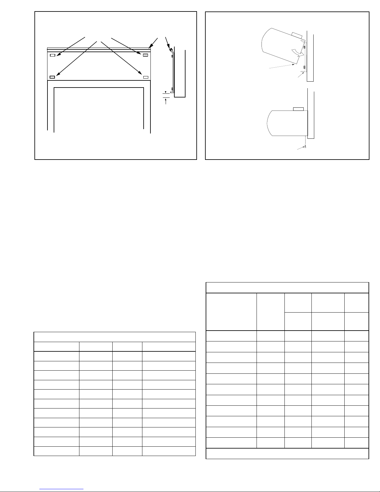
III. WALL PREPARATION
1. Position and center the mounting plate over the door
opening. The mounting plate must be positioned with the
45° lip and the rubber vibration gasket on top. Drill mounting holes on the mounting plate. See Figure 4.
2. Mark the wall in the center of each mounting plate hole.
The wall must provide sucient support for the Air curtain.
The mounting hardware (supplied by others) must be
capable of supporting a minimum of three times the net
weight of the Air curtain. See Weight Chart, Table 1. If
the location of the marks on the wall do not provide suitable support, mark and drill additional holes.
3. Drill the four holes as marked on the wall and attach the
mounting plate with anchors (if used) and the four mounting screws (provided by others).
WEIGHT IN POUNDS
Model Unheated Electric Steam/Hot Water
AHC10-1036 65 71 98
AHC10-1042 68 74 104
AHC10-1048 70 76 109
AHC10-2048 95 107 134
AHC10-2060 125 137 171
AHC10-2072 130 142 181
AHC10-2084 140 152 197
AHC10-2096 145 157 208
AHC10-3096 165 183 228
AHC10-3108 170 188 240
AHC10-3120 175 193 248
TABLE 1 - Weight Chart
IV. ATTACHING THE AIR CURTAIN TO THE
MOUNTING PLATE
1. Raise the unit over the door (air discharge nozzle facing
down) and on to the mounting plate. First, tilt the unit upward matching the top recessed edge of the unit to the top
45° angled lip on the mounting plate. See Figure 5.
2. Lower the unit into place, allowing it to rest on the lower lip
of the mounting plate.
3. After the unit is securely attached to the mounting plate, reinstall the two (2) locking screws at the bottom corners.
See Figure 5.
Model
AHC10-1036 1@½ 7.2 4.0 1.3
AHC10-1042 1@½ 7.2 4.0 1.3
AHC10-1048 1@½ 7.2 4.0 1.3
AHC10-2048 2@½ 14.4 8.0 2.6
AHC10-2060 2@½ 14.4 8.0 2.6
AHC10-2072 2@½ 14.4 8.0 2.6
AHC10-2084 2@½ 14.4 8.0 2.6
AHC10-2096 2@½ 14.4 8.0 2.6
AHC10-3096 3@½ 21.6 12.0 3.9
AHC10-3108 3@½ 21.6 12.0 3.9
AHC10-3120 3@½ 21.6 12.0 3.9
*Special 1/3 hp Two Speed Motor
-3-
#Motors
MOTOR DATA
120 V 1ø208/240 V 1ø460 V*
@HP
Motor
Amps
Table 2
Motor
Amps
Motor
Amps
1 ø
 Loading...