

Page 1
Bernee
®
1 / 8
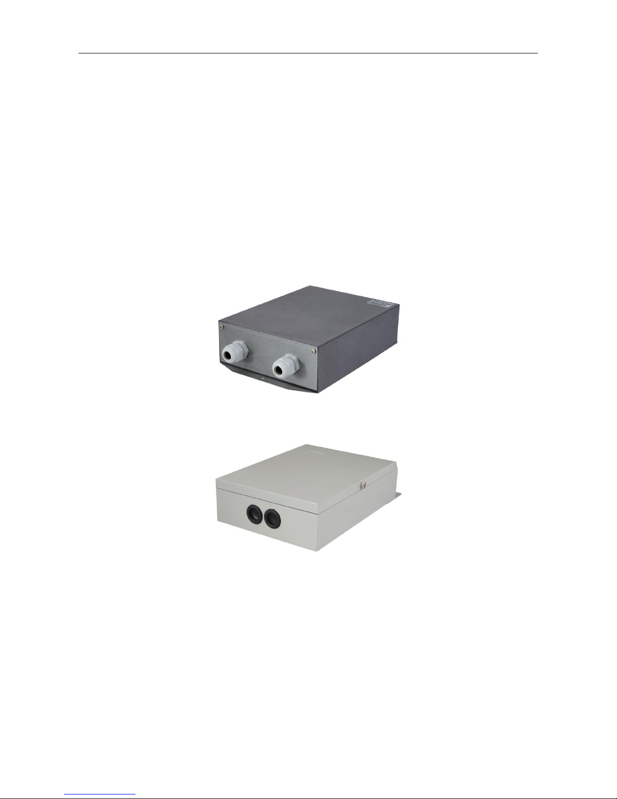
Indoor & Outdoor Decoder’s manual
BN-800F
BN-800G
BN-800F
BN-800G
Bernee production
----------------------------------------------------------------------------------------------------------
Page 2

Bernee
®
2 / 8
1. Equipment Profile:
As a kind of front-end equipment, decoder is used to control pan/tilt, lens, power supply, wiper and
light. Keyboard controller, matrix or PC system can use decoder to manage pan/tilt, lens as well as
assistant functions. Besides, the decoder is designed for anti-lightning and anti-interference circuit.
2. Features:
Adopt anti-interfering PIC single-chip, CPU builds-in watchdog circuit with photoelectronic
isolation.
Adopt anti-high voltage, anti-static and anti-lightning design, adding communication jamming
auto reset skill.
This decoder offers AC220V, AC24V, DC12V such-and-such three groups of power supplies for
devices like camera.
Pan/tilt voltage can be AC220V or AC24V (AC24V initiated)
Lens voltage ranges from DV6V to DC12V adjustable (8V initiated), applying for lens speed
adjustment.
Two groups assistant switchers control light, wiper or camera power supply.
Support selections among multi control protocols and multi communication baud rates, 0-63
addresses setting.
3. Specifications:
Models
BN-800F(Indoor)
BN-800G(Outdoor)
Power Supply
AC220V±10%, 50Hz±10%, 30W
AC220V±10%, 50Hz±10%, 50W
Address Code
Range
0~63
0~63
Pan/tilt
Operation
Voltage
AC220V/2A or AC24V/0.8A
AC220V/2A or AC24V/0.8A
Lens Voltage
DC6V~DC12V,600mA
DC6V~DC12V,600mA
Power Output
(DC)
DC 12V, 600mA
DC 12V,800mA
Power Supply
Output (AC)
AC 24V, 500mA
AC 24V,500mA
Communication
RS-485, 1200/2400/4800/9600Bit/s
RS-485, 1200/2400/4800/9600Bit/s
Protocols
Pelco-D, Pelco-P etc
Pelco-D, Pelco-P etc
Pan/tilt Control
Up/Down/Left/Right/Auto
Up/Down/Left/Right/Auto
Lens Control
Iris/Zoom/Focus
Iris/Zoom/Focus
Assistant Control
2 Relay(AC220V/5A)
2 Relay(AC220V/5A)
Operating
Environments
Indoor
Outdoor
Page 3
Bernee
®
3 / 8
Dimension
246×146×57mm
281×176×70mm
Operating
Temperature
-40℃~70℃
-40℃~85℃
Weight
1.52kg
2.35kg
4. Pan/tilt Setting:
Can control pan/tilt action of Up/Down/Left/Right/Auto. Pant/tilt voltage can be AC220V or AC24V
(precaution: excessive voltage will burn pan/tilt).
5. Lens Setting:
Can control lens iris, focus as well as zoom. Lens voltage is adjusted by potentiometer of circuit,
ranges from DC6V to DC12V. The higher the voltage is, the faster the lens speed is.
6. Auxiliary Control:
AUX1 and AUX2 is normal-open switcher, used for controlling light and wiper.
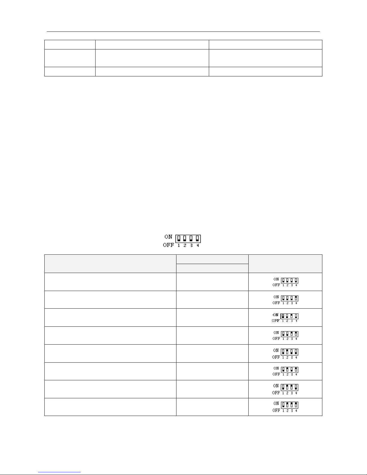
7. Protocol Setting:
4-digit dialup switcher (ON=1, OFF=0)
Protocol
ID
Dialup Switcher
1234
PELCO-D
0000
HY
0001
VICON:Surveyor99
0010
KALATEL(KDT-312)DCW0601
0011 PELCO-P
0100
HN-C
0101 SAMSUNG
0110
KODICOM-RX
KRE-301RX
0111
Page 4
Bernee
®
4 / 8
NEOCAM
1001 PIH1016
1010
B01
1011 RM110/S1601
1100 SANTACHI-450/9600
1111
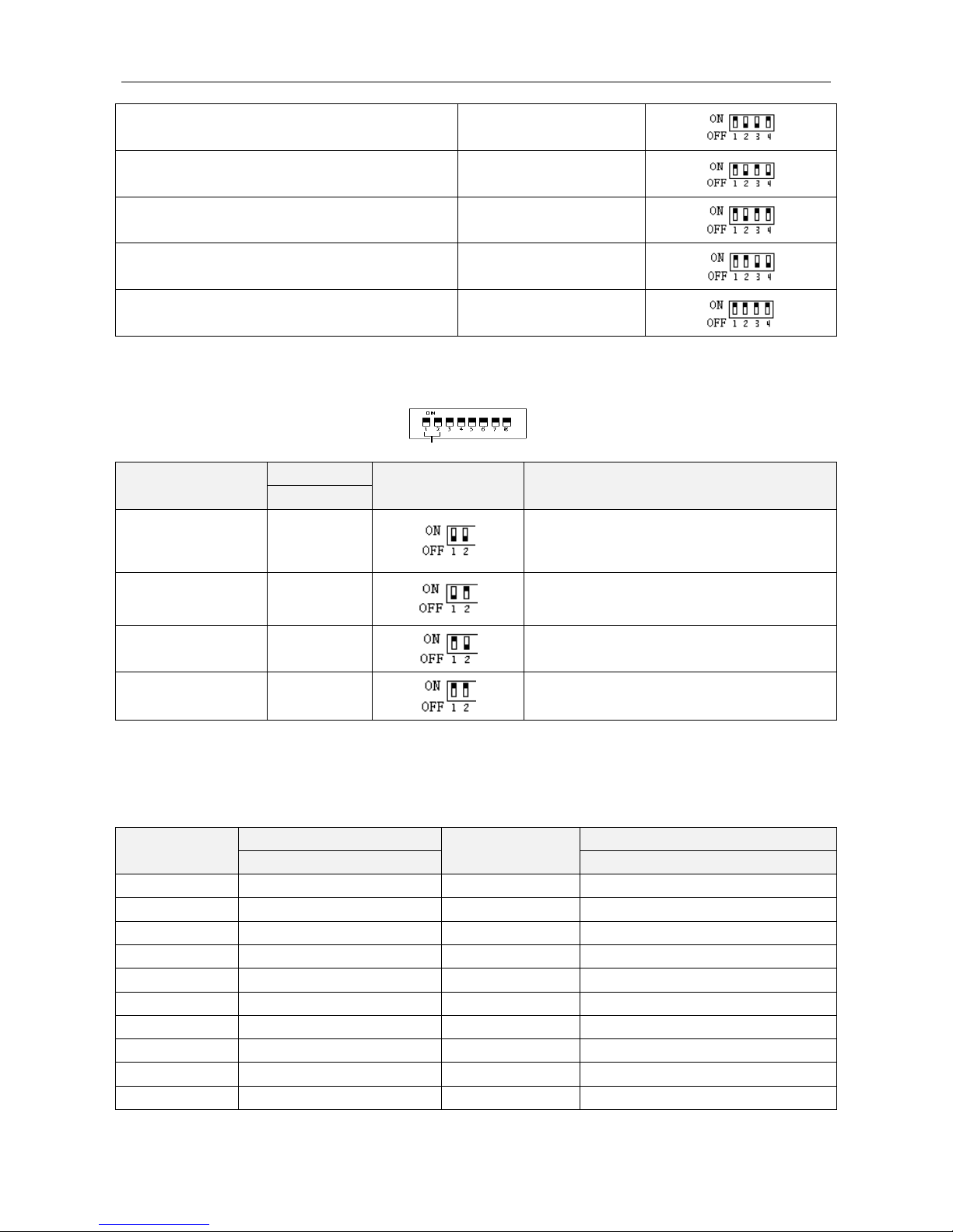
8. Baud Rate Setting:
1st and 2nd digit of 8-digit switcher
Baud Rate
ID
Dialup Switcher
Position
Notes
12
1200/19200
00
Auto identify 1200 protocol or 19200
protocol
2400
01
4800
10
9600
11
9. Address Code Setting:
3rd to 8th digits of 8-digit switcher (ON=1,OFF=0)
Number
ID
Number
ID
345678
345678
0
000000
32
100000
1
000001
33
100001
2
000010
34
100010
3
000011
35
100011
4
000100
36
100100
5
000101
37
100101
6
000110
38
100110
7
000111
39
100111
8
001000
40
101000
9
001001
41
101001
Page 5
Bernee
®
5 / 8
10
001010
42
101010
11
001101
43
101011
12
001100
44
101100
13
001101
45
101101
14
001110
46
101110
15
001111
47
101111
16
010000
48
110000
17
010101
49
110001
18
010110
50
110010
19
010011
51
110011
20
010100
52
110100
21
010101
53
110101
22
010110
54
110110
23
010111
55
110111
24
011000
56
111000
25
011001
57
111001
26
011010
58
111010
27
011011
59
111011
28
011100
60
111100
29
011101
61
111101
30
011110
62
111110
31
011111
63
111111
(1) Dialup switcher: ON=1; OFF=0.
(2) Address encoding is based on binary system.
(3) Some hosts addresses initiate as 0, and some initiate from 1.
10. Common Faults Analysis & Solutions
Fault Features
Analysis & Solutions
Powered light cannot shine
1. Whether supplied voltage is AC220V
2. Maybe power switcher shut or fuse burnt
Out of control
2. Whether PC system is normal and whether communication port
setting accords with hardware requirement
3. Whether address code switcher setting accords with controlled
camera address (for NO.1 camera address, some hosts show as
0; but some hosts show as 1)
4. Protocol setting incorrect
Close control available; remote
control unavailable
1. RS485 converter lacks driving force for output.
2. Wiring distance over 1200m should add RS485 repeater or
RS485 distributer.
11. Wiring Diagram:
Page 6
Bernee
®
6 / 8
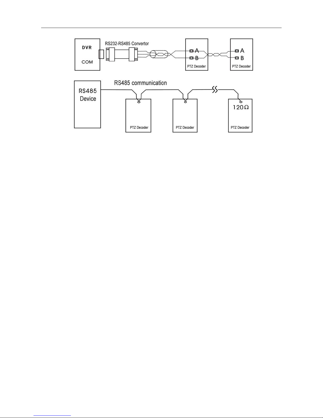
(1) Control line adopts twisted pair cable which is better than parallel line in transmission
distance.
(2) Decoder adopts dual-core STP (shielded twisted pair) with RS485 communication. Cable
length should be within 1200m. Decoder can adopt chain connection or star connection. RS
+( A),RS-( B)is signal end, connecting to A and B port of RS485 host (reverse connection
forbidden).
(3) Multi decoders connection should be finished between the two farthest decoders, moreover
adding 120Ω resistor.
12. RS485 controlled device use method:
Wiring method: matrix switcher directly connects to decoder. PC can adopt active or passive
RS232-485 converter for connecting with decoder.
When distance over 1200m or interference excesses, it is necessary to install a RS485 repeater.
When adopting star wiring, we’d better use RS485HUB which can turn 1 channel RS485 into 4
channels RS485. Thus all channels realize better isolation and less interference between each
other, besides effective transmission distance can also be lengthened.
When interference too serious or adopting non-twisted pair which leads to hard or disable control,
we should adopt RS485HUB or RS485 repeater suchlike devices.
13. Wiring Diagram:
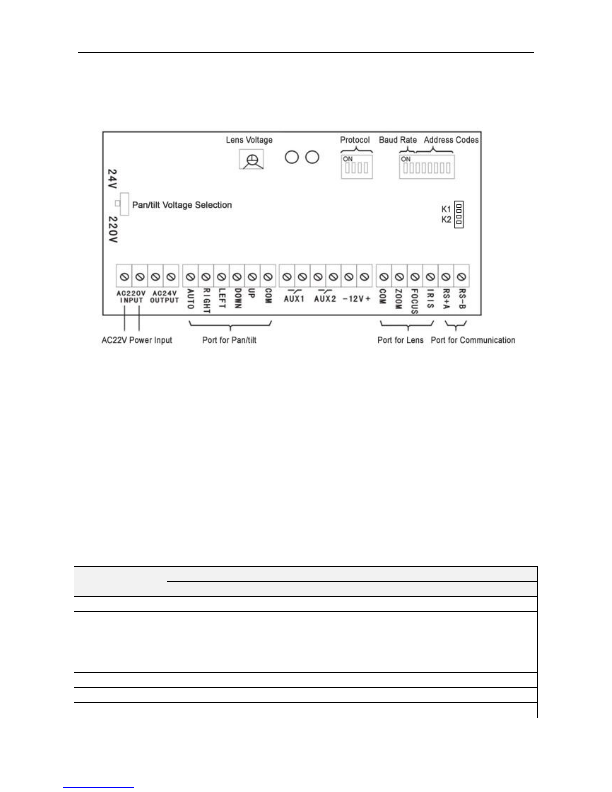
RS+ (A) refers to RS485 plus communication; RS-(B) refers to RS485 minus communication.
DC12V and AC24V refer to the wiring terminal of power supply for camera.
AUX1 and AUX2 refer to the control switchers of camera power supply, wiper or light.
Page 7
Bernee
®
7 / 8
AC220V INPUT refers to power supply terminal of decoder, external connecting to AC220V
power supply.
Wiring Diagram:
14. Usage of Decoder Test Function:
1) Switch <K1> terminal of <TEST> module of main board into short-cut state and enter test mode.
Then red indicator light shows as flickering.
2) In test mode, firstly dial 5th-8th digits of 8-digit switcher into related function window, then make
<K2> terminal short-circuit. Thus test function runs.
3) Finishing test, we must cut off <K1> terminal immediately, return to normal operation mode,
moreover, dial address code back to original position.
ID Function Definition of Decoder Test Status (using 5th-8th digits of 8-digit switcher, ON=1,
OFF=0):
Functions
ID
5678
Up
0000
Down
0001
Left
0010
Right
0011
Zoom+
0100
Zoom-
0101
Focus+
0110
Focus-
0111
Page 8

Bernee
®
8 / 8
Iris+
1000
Iris-
1001
AUX1
1010
AUX2
1011
 Loading...