

Page 1
1 2
Page 2

CAUTION: Read and follow all Safety Rules
and Operatin g Instr uctio ns bef or e Fi rst Use
of this Product.
TABLE OF CONTENTS
Specifications…………………………………2
Safety Rules…………………………………. 3-4
Unpacking…………………………………….5
Installation…………………………………….5
Struct ure and Functions…………………….6-7
Supplementary Safety Instructions………..7
Operation Regulations………………………8-10
Maintenance…………………………………11
Attention …………………………………….11
Assembly Diagram and List………………..12-15
Page 3

Model No PT 250
Motor 1500W (Please choose proper power source, voltage and
No. of Blade 2
Cutterhead rpm
Weight 27 kg
T echnical data-Planer
Cutting Width(max)
Cutting Depth (max) 2mm
Angle fence 610x127mm
Fence Angle
Working Table 920x254 mm
Technical data-Thicknesser
SPECIFICATIONS
frequency that are shown in the label for your machine.)
8500 min
254 mm (10″)
90°-135°
-1
Cutting Width(max)
Cutting thickness(max) 120mm
Cutting Depth (max) 2mm
Working Table 380x254mm
254 mm (10″)
SAFETY RULES:
WARNING: When using electric tools, basic safety precautions should always be followed to reduce the risk
of fire, electric shock and personal injury, including the following.
Read all these instructions before attempting to operate this product and save these instructions.
(1) Keep work area clear
- Cluttered area and benches invite injuries.
(2) Consider work area environment
- Don’t expose electric tools to rain.
- Do not use electric tools in damp or wet locations.
- Keep work area well lit.
- In particular, no inflammable liquids or gases must be present.
(3) Guard against electric shock
- Avoid body contact with earthed or grounded surface.
(4) Keep children and other persons away
- Don’t let especially children, persons not involved in the work touch the tool or extension cord and keep
them away from the work area.
(5) Store idle tools
- When not in use, tools should be stored in a try locked up place, out of reach of children.
(6) Don’t force the tool
- It will do the job better and safer at the rate for when it was intended.
(7) Use the right tool
3
Page 4

- Don’t force small tools to do the job of a heavy duty tool.
- Don’t use tools for purposes not intended: for example, don’t use circular saws to cut tree limbs or logs.
(8) Dress properly
- Don’t wear loose clothing or jewelry. They can be caught in moving parts.
- Rubber gloves and non-skid footwear are recommended when working outdoors.
- Wear protective hair covering to contain long hair.
(9) Use protective equipment
- Use safety glasses.
- Use face or dust mask if cutting operations create dust.
(10) Don’t abuse cables
- Never carry tool by cable or rank it to disconnect it from socket. Keep cable from heat,
oil and sharp edges.
(11) Do not abuse the cord
- Nev er yank the cord to disconn ect it from the socket. Keep the cord aw ay from heat, oil and sharp
edges.
(12) Secure work
- Where possible use clamps or a vice to hold the work. It is safer than
using your hand.
(13) Don’t overreach
- Keep proper footing and balance at all times.
(14) Maintain tools with care
- Keep cutting tools sharp and clean for better and safer performance.
- Follow instruction for lubricating and changing accessories.
- Inspect tool cords periodically and if damaged have them repaired by an authorized service facility .
- Inspect extension cords periodically and replace if damaged.
- Keep handles dry, clean and free from oil and grease.
(15) Disconnect tools
- When not i n use, before serv icing and when ch anging acces sories such as b lades, bits and cutter s,
disconnect tools from the power supply.
(16) Remove adjusting keys and wrenches
- Form the habi t of check ing to see tha t ke ys and adjus ting w renches are r em oved f r om the tool bef or e
turning it on.
(17) Avoid unintentional starting
- Ensure switch is in “off” position when plugging in.
(18) Use outdoor extension leads
- When the tool is used outdoors, use only extension cords intended for outdoor use and so marked.
(19) Stay alert
- Watch what you are doing, use common sense and do not operate the tool when you are tired.
(20) Check damaged parts
- Before further use of tool, it should be carefully checked to determine that it will operate prope rly
and perform it’s intended function.
- Check for al ignment of moving parts, binding of moving parts, m ounting and an y other condi tions that
may affect it’s operation.
- A guard or other part t hat i s dam ag ed s hould be properl y repai r ed or r epl ac ed b y an auth or i z ed ser v i c e
centre unless otherwise indicated in this instruction manual.
- Have defective switches replaced by an authoeized service centre.
4
Page 5

- Do not use the tool if the switch does not turn it on and off.
(21) Warning
- The use of any acces sory or attachm ent other t han one recom mended i n this inst ruction m anual ma y
present a risk of personal injury.
( 2 2 ) Have your tool repaired by a qualified person
- This elec tr i c tool c ompli es w i th the r el evant saf et y r ules . Repairs s houl d only be carr i ed out by q ual i f ied
persons using original spare parts. Otherwise this may result in considerable danger to the user
(23) Never use the machine without the appropriate guard in place and correctly adjusted.
(2 4) Do not use knives, which are blunt as this increases the danger of kickback.
(2 5 ) Any portion of the cutter block not being used for planning shall be guarded.
( 2 6 ) When planning short workpieces, a push-stick should be used.
(2 7 ) When p lanning narrow workpi ces additional measures. Such as of hor izontal pressure dev ices and
spring-loaded guards, may be necessary to ensure safe working.
( 2 8 ) Do not use the tool cut rebate.
( 2 9 ) The effectiveness of the device for the prevention of kickback and the feed spindle should be
regularly inspected to ensure safe operation.
(30)Tools equipped with chip collection and extractor hoods shall be connected to the dust and
chip-collecting device.
( 3 2 ) Use the tool only for wood or similar materials.
When the blade be abraded 95%, you must change it to the new one, which must meeting EN847-1.
(3 3 ) Need two persons for moving round the workshop due to its heavy weight.
( 3 4 ) The machine should be fixed on the floor by screws when operating.
.
SUPPLEMENTARY SAFETY INSTRUCTIONS
⑴ Regularly check that blades and lock bars are locked tight in cutterblock.
⑵ Max. allowable blade projection over cutterblock 1.0mm/0.004 inch +10%.
⑶ Never remove any of the machine’s safety guards other than for servicing and repair work. Keep guards
operational at all times.
⑷ Set and secure safety guards in position before operating machine.
⑸ When operating machine in enclosed spaces connect to a dust collector.
⑹ T his machine must be safety earthed. The yellow/green (green) lead is the earth conductor.
⑺ Regularly check anti-kickback fingers for proper operation.
⑻ Al ways wear eye protection.
⑼ Rebating, tenoning, moulding and recessing may not be undertaken without the use of special guards.
⑽ Never make jointing or planning cut deeper than 2 mm.
USER RESPONSIBILITY
This machine will perform in conformity with the description contained in this manual when installed,
5
Page 6
operated, maintained and repaired in accordance with the instructions provided.
This mac hine must b e checked periodically. Defective equipm ent (including p ow er cable) should not b e
used. Parts that are broken, missing, plainly worn, distorted or contaminated, should be replaced
immediately. Should such repair or replacement become necessary, it is recommended that such repairs be
carried out by qualified persons.
This mac hi ne or any of i ts parts s hould not b e al ter ed or c hang ed or c hang ed from standard sp ec i f i c ati ons.
The user of thi s machine shal l h ave the sole r es p ons i b il it y f or any m al function which res ul ts f r om imp r oper
use or unauthorized m odification from standard specification, Faulty maintenance, damage or improper
repair.
UNPACKING
Check for shipping damage. If damage has occurred, a claim must be filed with carrier. Check for
completeness. Immediately report missing parts to dealer.
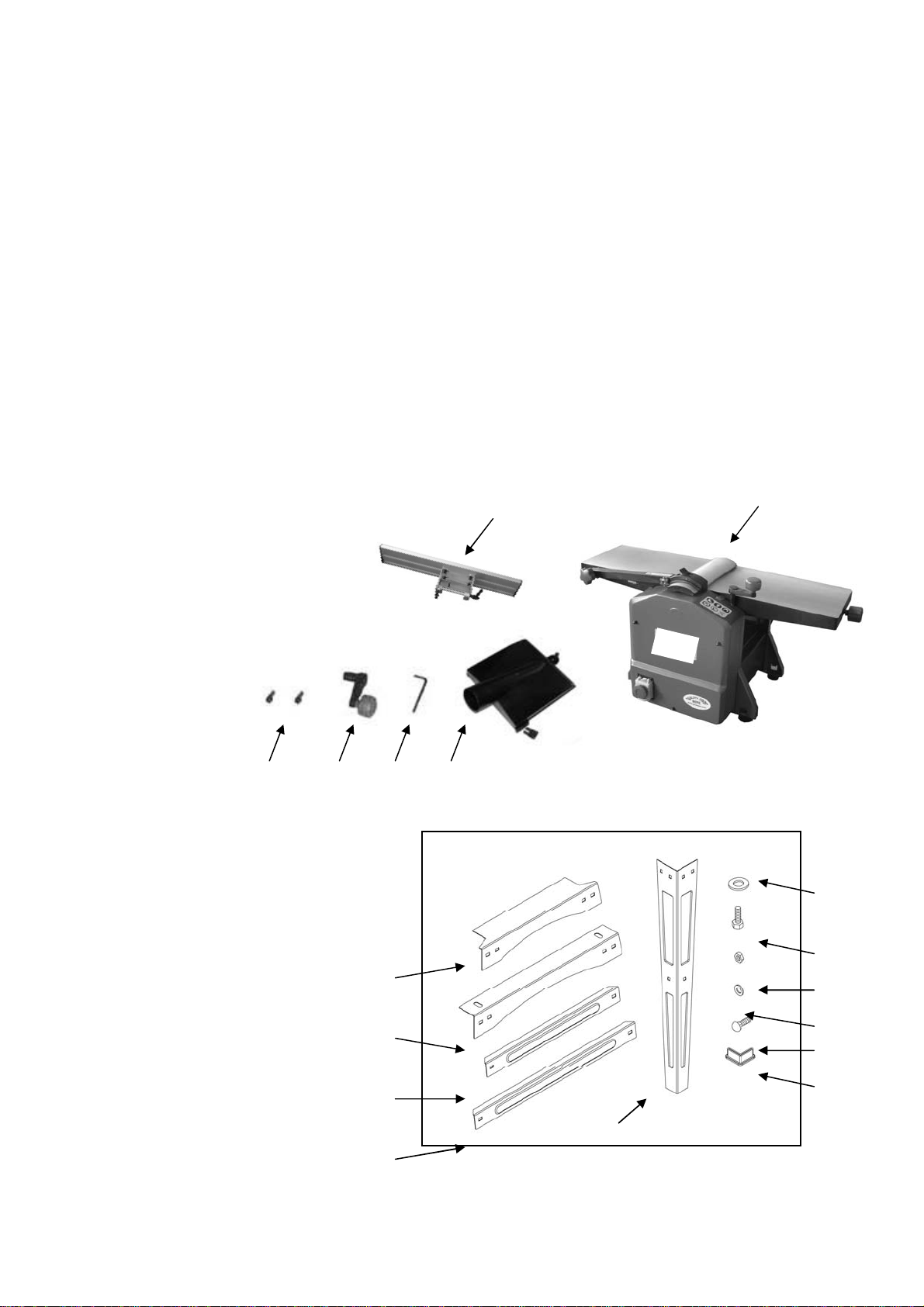
The machine i s shipped comp lete in one carton. A dditional parts w hich need to be fastene d to machine
should be located and accounted for before assembling. Refer to figure 1and figure 2.
Parts of machine
A. Planer and Thicknesser
B. Angle fence
C. 4mm Hex wrench
D. Handle assembly
E. Socket head bolt
F. Dust chute
Parts of stand
Description QTY
E F
C D
Figure 1
B
A
G.Short top frame 2
H. Long top frame 2
I. Short brace 2
J. Long brace 2
K. Leg 4
L. 8mm flat washer 4
M. M8X30 hex bolt 4
N. M6 hex nut 24
O. 6mm flat washer 24
P. M6X12 carriage bolt 24
G
H
I
J
L
M
N
O
P
Q
K
Figure2
6
Page 7
STRUCTURE AND FUNCTIONS
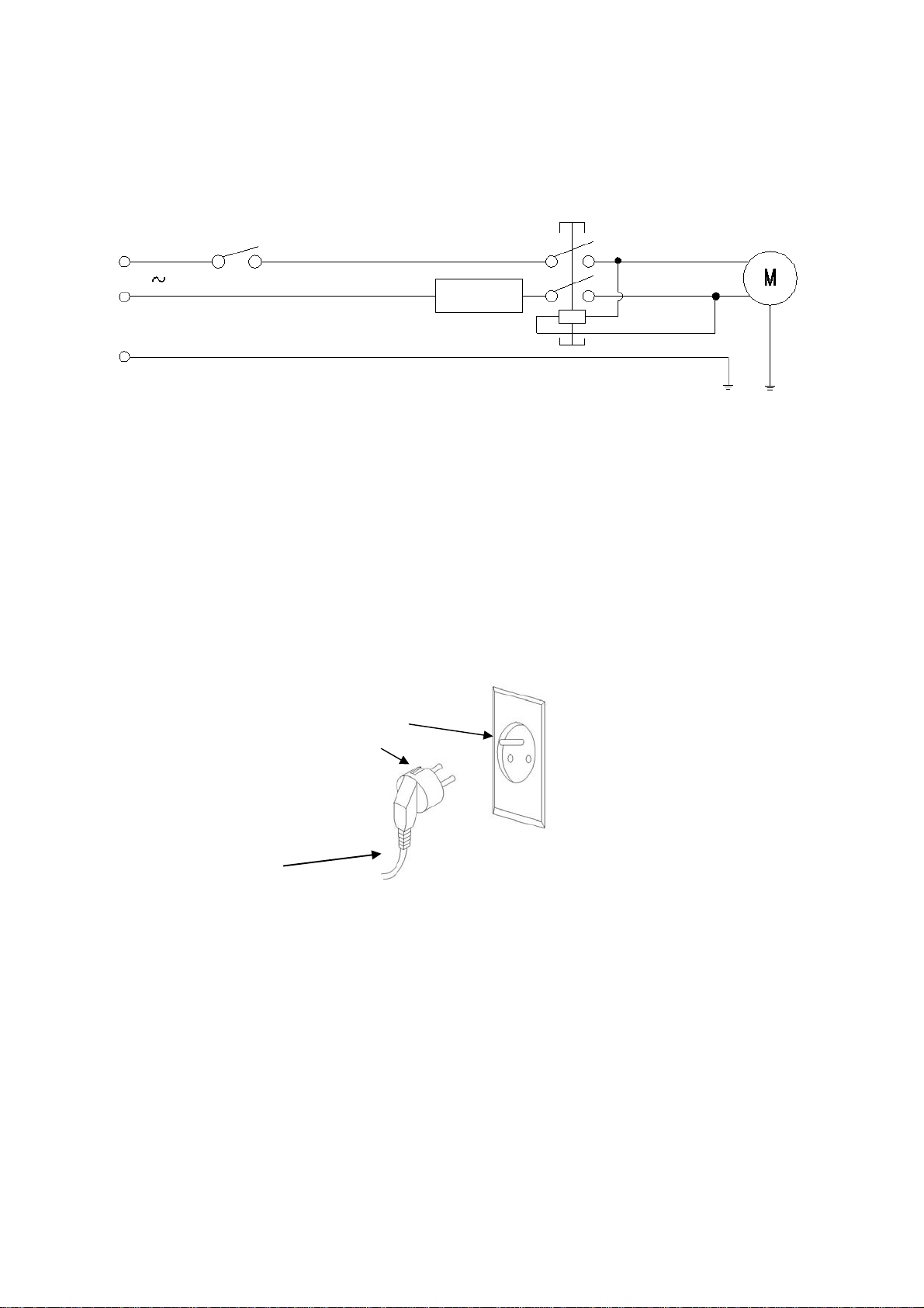
The surface p laner-thickness er is a transportable el ectric tool. The m achine is driven by a sing le-phase
series m otor, and it is double i nsulated. It i s used to planer- thicknes ser wood. It has the charact eristi cs of
rational structure, easy operation and high efficiency. Refer to figure 3.
Safety Switch
230V
Circle Breaker
Figure 3
POWER SOURCE
WARNING:Do not connec t planer-thicknesser to the p ower source until al l assembly steps have been
compl eted. The m otor is desig ned f or oper ation o n the v ol tage and f r equenc y sp ecif ied. N orm al l oads will
be handled saf ely on v oltages not m ore than 10% a bov e or below sp ecified v oltage. Runni ng the until on
voltages which ar e not w ithin rang e may cause ov erheating and m otor b urnout. H eavy lo ads requi re th at
voltage at motor terminals be no less than the voltage specified on nameplate.
GRONNDING INSTRUCTIONS
Refer to figu re 4
Properly Ground Outlet
Grounding Prong
3-Prong plug
Figure 4
WARNING: Improper connection of equipment grounding conductor can result in the risk of electrical shock.
Equipment should be grounded while in use to protect operator from electrical shock.
- Check w i th a q ual ified electr i c i an if you do n ot un d erstand grounding instr ucti ons or i f you are in doub t as
to whether the tool is properly grounded.
-This tool is equipped w ith an approved c ord rated at 230v and a 3-prong groundi ng type plug for you
protection against shock hazards.
-Grounding p lug shoul d be p lugg ed direc tly int o a prop erly i nstalled an d gr ounded 3- pr ong gr ounding -typ e
receptacle, as shown.
-Do not remove or alter grounding prong in any manner. In the event of a malfunction or breakdown,
grounding provides a path of least resistance for electrical shock.
7
Page 8
OPERATION REGUL ATIONS
ATTENTION: Make sure that the switch is in off posit ion before adjusti ng the cutting dep th, replacing or
adjusting the blades. Make sure the blade screws are securely tightened.
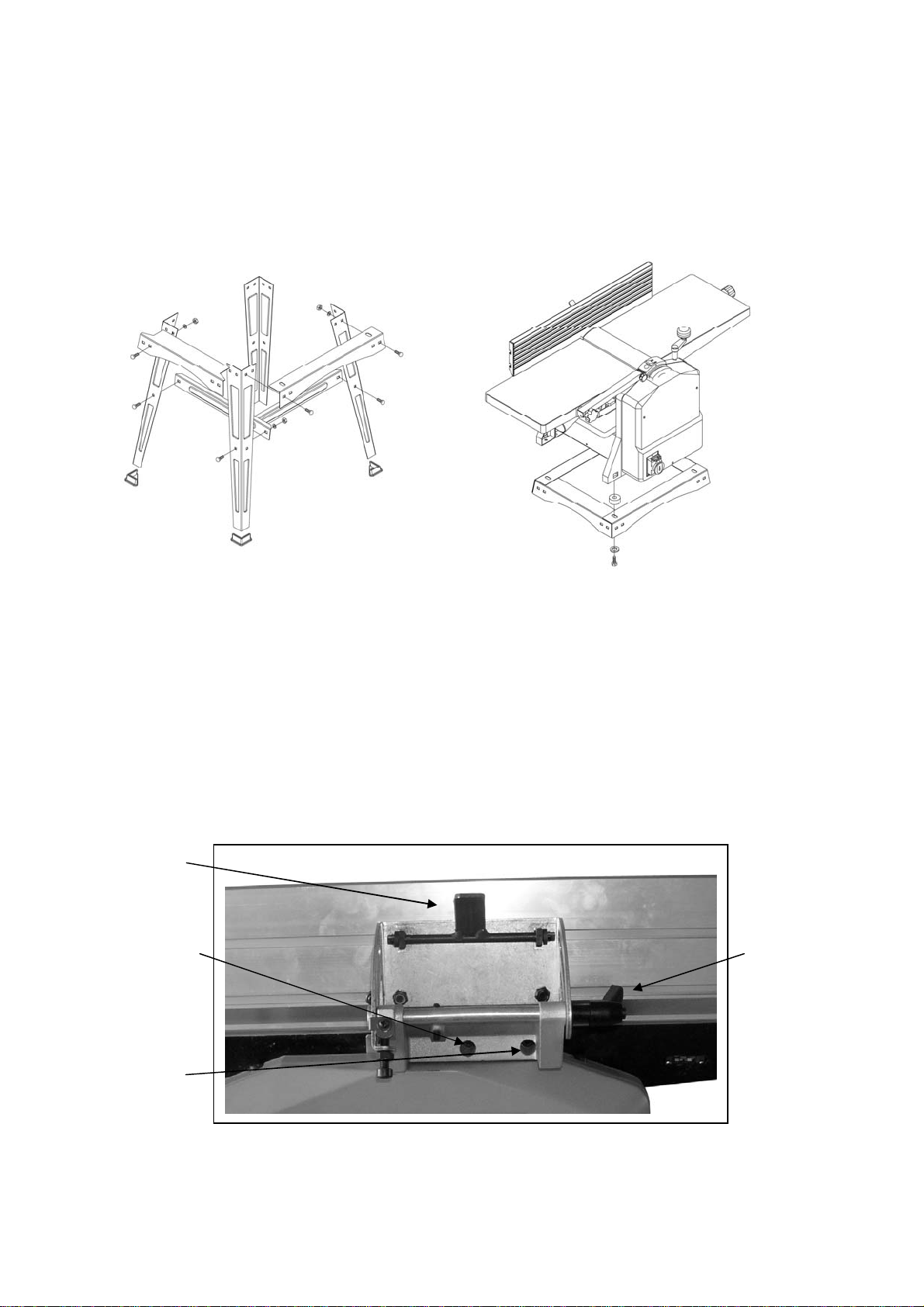
Assemble stand with M6 hex nut, 6mm flat washer and carriage bolt. Then install the machine to the stand
and secure it with M8X30 hex bolt and 8mm flat washer
OVERLOAD PROTECTION
If the motor protection responds, this always indicates that the motor is overloaded. The cause must be
located and the fault eliminated.
If the motor is overloaded or in the event of power failure, the motor switches off automatically. The
machine can not be switched on again until the motor is cooled down or the power supply has been
restored.
SETTING A NGLE FENCE
Insert the socket head bolt into the slot A and B. Then loosen C to adjust angle fence.
Turn M down, guide fence can be moved to left or right.
Refer to figu re 5
M
A C
B
Figure 5
8
Page 9
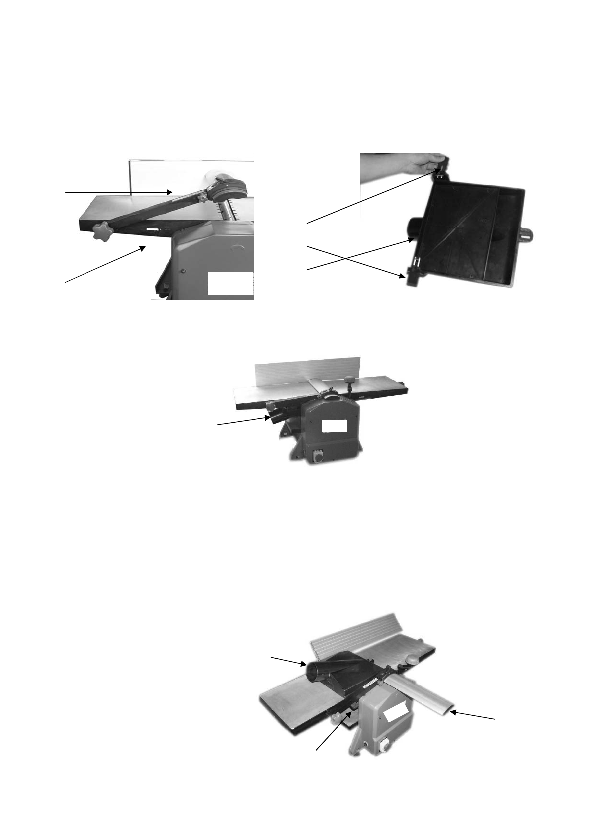
CHIP EXTRACTION
To ensure trouble free and reliable operation on enclosed premises, the machine must be connected to an
extractor unit at the dust chute E (accessory)
DUST CHUTE CONNECTION WHEN PLANING :
- Lift up the blade guard arm F so that the longitude holes G being exposed;
- Pull out the key H on both sides of the dust chute E;
- Move down the thickness table to the lowest position, and insert the dust chute E;
F
H
E
G
Figure 6
- The dust chute E is so positioned that both keys H are in line with the longitude holes G. Then push both
keys H into the longitude holes G. (refer to Fig. 6 )
E
Figure 7
DUST CHUTE CONNECTION WHEN THICKNESSING:
-Slide the fence to right side, and turn to 135°
-Remove the blade guard K and place the dust chute E(See Figure 8).
-The dust chute E is so positioned that both keys H are in line with the longitude holes G. Then push both
keys H into the longitude holes G (See Figure 6).
The minimum air velocity at the extractor connection must be 20m/s(65ft/sec) to ensure an optimum
extraction.
E
K
H
9
Page 10
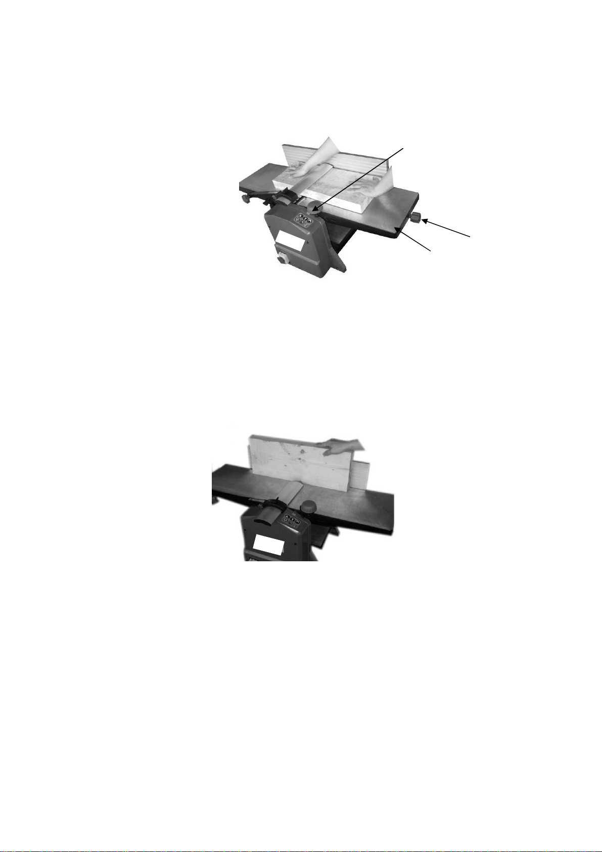
Figure 8
SETTING OF GUARD
Height adjustment is made with the lever mounted on the left side of the machine. After lifting the lock lever
the blade cover can b e s l i de ways to se t t he r equire d s tock width for j oi nti ng . Push l ock l ever dow n to l o c k
guard extrusion in position.
Refer to Figure 9. M
L
N
Figure 9
PLANING
The cutting depth i s set by han dle L at t he fr ont table p late N b y m eans of th e scale for c utting d epth M .
Cutting depth between 0.5 and 1.5 mm (1/64~1/16 in.) will produce the best surface.
WARNING: The part of the cutter head not used has to be covered by the knife guard.
Take up a working position so that you are always on one side of the machine away from the area directly in
front of or behind the cutterhead. Place both hands on the workpiece with the fingers. Do not hold on to the
workpiece edges.
Only workpieces should be planed which rest firmly on the machine and can be safety guided.
Refer to figu re 10.
Figure 10
THICKNESSING
-Set the desired height with handle assembly at spindle with reference to scale.
1 turn =3mm
-Slide in narrow wood in the middle.
When thicknessing the table must be lubricated regularly with lubricant. After having worked for a long
period or when planing wet wood it may occur that the workpiece stops while pulling in.
WARNING: Swi tch off the m ac hine imm edi ately in c ase of fai lur e. Do not r em ove chi ps and sp li nters f rom
the tables while the machine is running.
Short workpieces should not be planed.
REPLACING BLADES
Disconnect machine from power before servicing!
Replacing blades
10
Page 11

-Unplug the planer-thicknesser from power source and turn the switch to “off” position.
-Block the blade guard from closing down.
-Loosen and remove three blade lock screws securing blade and blade clamp.
-Lift blade and blade clamp from cutterhead.
-Clean any sawdust and resin buildup from cutterhead and blade clamp.
-Place blade clamp against the replacement blade and replace in cutterhead.
-Secure blade and blade clamp using three blade lock screws. Do not over-tighten blade lock screws first.
Note: Check blade height at both of blade
-Tighten blade lock screws.
-Recheck blade adjustment and make sure blade is still level with outfeed table.
-Repeat the procedure to replace the other blade.
-Remove the scrap wood and release blade guard.
-Make sure all the blade lock screws are tight and snug.
NOTE:
-The blades which used with the tool may be replaced.
-the blades used in this tool can not be used to rebate
.
MAINTENANCE
Prior to doi ng any m aint enance work, al ways pul l out the mains p l ug. The pr ot ect i ng ho od which has been
removed to the side has to be mounted again after the maintenance work.
Machine care
The planer-thicknesser is designed with a low maintenance requirement. The bearing are greased for life.
After approximately 10 hours of operation we recommend to lubricate the following parts:
-bearings of the feed-in and feed-out rollers.
-bearings of pulley and gear wheel of the belt.
Treat threaded spindles for the height adjustment of the thicknessing table with dry lubricant only!
The table surface and feed-in / feed-out rollers should always be kept clean of resin.
Dirty feed-in rollers and feed-out rollers have to be cleaned.
In order to prevent the motor from overheating, regularly check that no dust has accumulated on the
ventilation apertures of the motor.
After a prolonged period of operation, users are recommended to have the machine checked by an
authorized customer service shop.
Tool care
The cutter head, clam ping devices , knife supp orts and knives used on the m achine must b e freed fr om
resin regularly as a clean tool improves the cutting quality. This can be done by soaking the clamping
devices , k ni f e s upp or ts and r eversibl e k ni ves for 24 hour s i n par af f i n, w hi t e sp i ri t or c om m er c i ally av ai l abl e
resin remover.
Tools m ade of alumini um may only be d eresini fied w ith cleani ng agents w hich do n ot corr ode this k ind of
material.
ATTENTION!
Through poor conditions of the electrical MAINS, shortly voltage drops can appear when starting the
EQUIPMENT. This can influence other equipment (eg. Blinking of a lamp). If the MAINS-IMPEDANCE
Zmax<0.464 OHM, such disturbances are not expected. (In case of need, you may contact your local
supply authority for further information).
11
Page 12
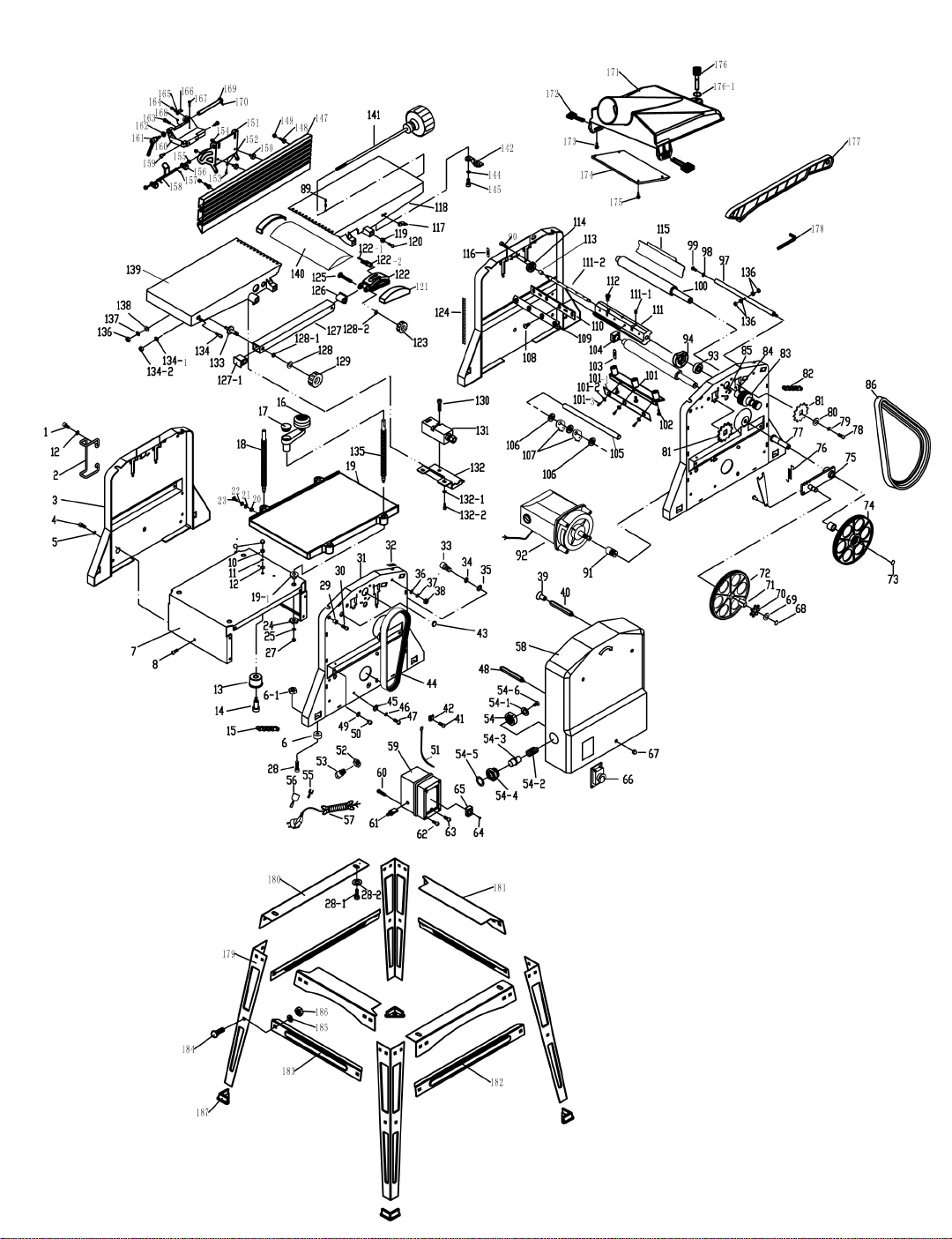
Page 13

No. Description Qty. No. Description Qty.
1 M5X10 Socket head bolt 4 42
2 Cord wrap 2 43
3 Side plate 1 44
4 M5X10 Socket head bolt 11 45
5 Ф5 Locking washer 11 46
6 Underprop 4 47
6-1 M8 Hex nut 4 48
7 Motor covering 1 49
8 M5X18 Pan head screw 1 50
9 M5 nut 1 51
10 M5 Hex nut 1 52
11 Ф5 Locking washer 1 53
12 Ф5 Flat washer 1+4+ 54
13
14
15
16
17
18
19
19-1
20
21
22
23
24
25
27
28
28-1
28-2
29
30
Tention Wheel
Shaft
Chain
Crank Assembly
Plug
Threaded spindle,short
Working Table
Threaded spindle nut
M5 Hex nut
Ф5 Flat washer
Pointer
M5X16 Pan head screw
Chain wheel
Ф6 Flat washer
M6 Lock nut
M8X12 Socket head bolt
M8X30 Hex head nut
Ф8 Flat washer
Sleeve
M5X20 Socket head bolt
1 54-1 Adjusting washer 1
1 54-2 Spring 1
1 54-3 Rod 1
1 54-4 Sleeve 1
1 54-5 Sign 1
3 54-6 M4X8 Pan head screw 1
155
456
157
158
159
160
4 61 Thermo-protector 1
4 62 Pan Head Self Tapping Screw 4
463
464
465
466
467
468
Cable Clamp
Rubber buffer
Flat belt
Ф5 Flat washer
Ф5 Locking washer
M5X12 Socket head bolt
Rod,long
Ф5 Flat washer
M5X6 Socket head bolt
Line(700mm 2G1.0mm2)
plastic locknut
strain relief
Nut
Locking line
Rubber set
Power cable
Protecting hood
Switch box
Pan Head Self Tapping Screw
Pan Head Self Tapping Screw
Pan Head Self Tapping Screw
Terminal
Switch
M5 Nut
Ф9 Locking ring
6
2
1
4
4
4
1
4
4
1
3
3
1
6
6
1
1
1
2
3
2
4teams
1
3
1
31
32
33
34
35
36
37
38
39
40
Side plate
Scale for cutting depth
M8x16 Socket head bolt
Ф8 Locking washer
Ф22XФ8X2 Flat washer
Ф8 Flat washer
Ф8 Locking washer
M8 Hex nut
Hex nut
Rod,long
169
170
171
172
173
174
1 74.1
1 74.2
2 74.3
Ф16XФ9X2 Flat washer
Chain wheel
Square sleeve
Gear wheel
Ф12 Retaining ring
Belt wheel
Pinion
Belt Wheel
Needle bearing
2 75 Wing,cpl. 1
1
1
1
1
1
1
1
1
1
Page 14

No. Description Qty. No. Description Qty.
A
41
77
78
M5X8 Pan head screw
Arbor
M6X10 Socket head bolt
476
1 120
2 121
79 Ф6 Locking washer 2 122
80
81
82
83
84
85
86
87
88
90
91
92
93
94
97
98
99
100
101
101-1
101-2
101-3
102
103/116
104
105
106
107
108
109
110
111
111-1
111-2
112
113
114
115
117
Ф6 Flat washer
Chain wheel
Chain
Belt disk
M6X6 Set screw
M5X12 Socket head bolt
Poly v -belt
M6X6 Set Screw
M5X12 Socket head bolt
Set Screw
Motor belt wheel
Motor
Grooved ball bearing
Bearing cover
Strut
Ф8 Flat washer
M8X12 Socket head bolt
Feed-out roller
Ratchet Sheet metal deflector
Adjusting Block
Ф5 Flat washer
M5X10 Sock head bold
M5X25 Socket head bold
Retracting spring
Bearing bush
Rod
Flat washer
Ratchet
M6X16 Bolt
clamping device
Knives
Knife stalk
M6X16 Set screw
Arbor
Adjusting bolt
Needle bearing
Bearing Cap
Sheet metal deflector
Plastic pointer
2 122-1
2 122-2
1 123
1 124
2 125
3 126 Cover 1
1+2 127
1 127-1
1 128
1 128-1
1 128-2
1 129
1 130
1 131
1 132
1+1 132-1
1 132-2
2 133
1 134
1 134-1
3 134-2
3 135
3 136
3 137
5 138
1 139
47 140
45 141
8 141
2 142
2 144
1 145
4 147
1 148
4 149
1 150
1 151
1 152
1 153
Retracting spring
M5X20 Socket head bolt
Cover
Arc cover
Parallel pin 3X35
Impacted wrench
Hand knob
Scale
Stud bolt
Square tube
Cover
Spacer
Ф8 Locking ring
Ф6 Locking ring
Hand knob
M4X27 Socket head bolt
Limit Switch
Switch cover
Ф
5 Flat washer
M5X8 Socket head bolt
Stud bolt
Impede stalk
Ф6 Locking washer
M6 Hex nut
Threaded spindle,long
M6 Hex nut
Ф6 Locking washer
Ф6 Flat washer
Rear table top
Knife guard
Spindle
Tessera
Clamping
Ф5 Lock washer
M5X12 Socket head bolt
Guide fence
M8X10 Hex head nut
M8 Lock nut
bolt
ngle scale
M6 Hex nut
M6X20 Socket head bold
1
4
2
1
1
1
1
1
1
1
1
1
1
1
1
2
1
1
4
4
1
1
1
1
1
1+4
1
1
1
1
1
1
1
2
2
1
2
2
2
2
1
1
Page 15

No. Description Qty. No. Description Qty.
118
119
156
157
158
159
160
161
162
163
164
165
166
167
168
169
170
171
172
173
174
Front table top
Sliding block
Socket head bolt
Ф3X8 Spring pin
Key assembly
Set Screw
Angle base
Handle
Ф6 Flat washer
M5X20 Socket head bolt
M4X8 pan head screw
Ф4 Flat washer
pointer
M5X25 socket head bolt
M5 Hex nut
Locking rot
Ф3X8 Spring pin
Dust collector
Key assembly
Pan Head Self Tapping Screw
Cover
1 154
4 155
2
2
2
2
1
1
1
2
1
1
1
1
1
1
1
1
2
2
1
175 Pan Head Self Tapping Screw 4
176
M6 pipe split lock handle knob
1
176-1 Split ring 1
177 Handlspike 1
178
Hex wrench
1
179 Stand 4
180 Front and Back Support 2
181 Side Support 2
182 Side Support 2
183 Front and Back Support 2
184 M6*12 Bolt 24
185 Φ6 Flat Washer 24
186 M6 Hex Nut 24
187 Foot 4
M5 Locking nut
Locking washer
2
2
 Loading...