

Page 1
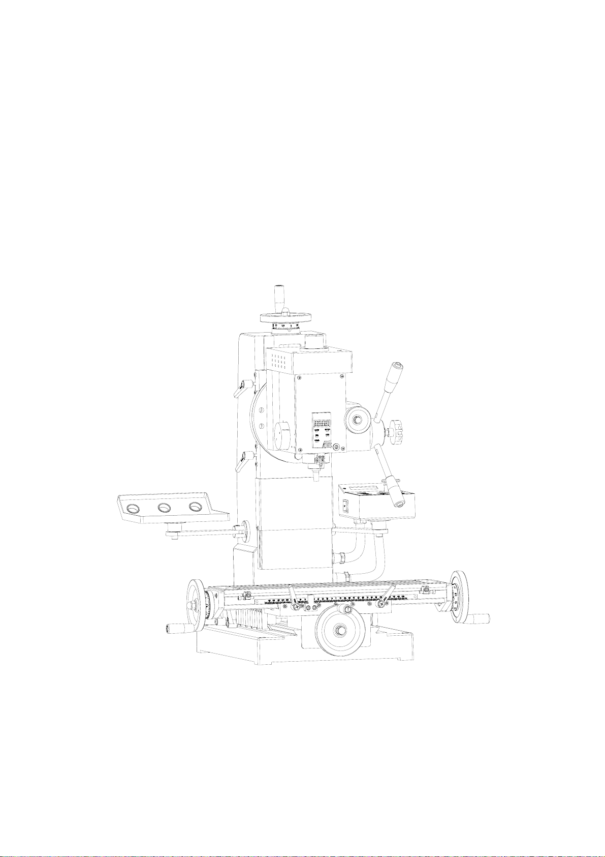
SUPER MILL MACHINE
Model: BF 20 SUPER
Instruction manual
Please read this instruction manual thoroughly and follow all directions carefully.
1
Page 2

IMPORTANT SAFETY INSTRUCTION
READ ALL INSTRUCTIONS AND WARNI NG S BEFORE USING THIS TOOL
Operator, Please Remember
1. When using electric tools, machines or equipment, basic safety precautions should
always be followed to reduce the risk of fire, electric shock, and personal injury.
2. Keep work area clean. Cluttered areas invite injuries.
3. Consider work area conditions. Do not use machines or power tools in damp, wet,
or poorly lit locations. Do not expose equipment for rain, keep work area well lit.
Do not use tools in the presence of flam-mable gases or liquids.
4. Keep children away, all children should be kept away from the work area.
5. Guard against electric shock. Prevent body contact with grounded surfaces such as
pipes, radiators, ranges, and refrigerator enclosures.
6. Stay alert. Never operate if you are tired.
7. Do not operate the product if under the influence of alcohol or drugs. Read
warning labels on prescriptions to determine if your judgment or reflexes might be
impaired.
8. Do not wear loose clothing or jewelry as they can be caught in moving parts.
9. Wear restrictive hair covering to contain long hair.
10. Use eye and ear protection. Always wear.
11. Keep proper footing and balance at all times.
12. Do not reach over or across running machines.
2
Page 3

CONTENT
SPECIFICATIONS
SPECIFICATIONS
PACKING LIST
XN2 FEATURES
IDENTIFICATION
MACHINE SET UP
UNPACKING AND INSTALLATION
TRANSMISSION SYSTEM
OPERATION AND MAINTAINANCE
INITIAL START
WEDGE ADJUSTMENT
REFERENCE
TROUBLESHOOTING
ELECTRICAL CIRCUIT DIAGRAM
PART DIAGRAM
PARTS LIST
3
Page 4

I. Specifications
XN2 has a advanced DC brushless and variable speed control system. With large start
torque, high accuracy and steady speed. It has a display when drilling with touch switch.
Friendly operating interface, easy to read and operate.
The spindle is able to tapping and interlock with the spindle.
The Y travel is available through movable column and headstock, the rigidity of the
spindle is much more better.
Specifications
Motor spec. 230V/500W DC brushless motor
Spindle speed 50-2500r/min
Spindle taper MT 2
Speed ratio 1:2
X travel 250mm
Y travel 160mm
Z travel 300mm
Thread pitch of lead screw 2mm
Lead screw diameter M14
Max distance between spindle and table 320mm
Table size 130mm*500mm
T--slot 8mm
Spindle bush travel 60mm
Max tapping size(HT200) M8
Max tapping size(45) M6
Max drill diameter(HT200) φ13
Max drill diameter(45) φ10
Max milling diameter φ30
Net weight 120Kg
Overall dimension(L*W*H) 610*610*780
4
Page 5
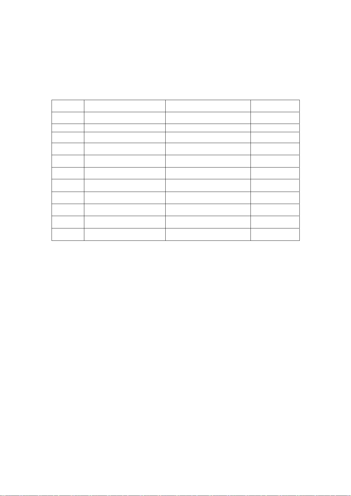
Packing List
No Name Description Q’ty
1
2 Manual 1
3
4
5
6
7
8
9
10
11
Milling machine XN2 1
Draw bar B16 1
Oblique wedge 1
Drill chuck with key JS13/D4 1-13mm 1
Variable speed handle 1
Oil Can 1
Double end wrench 8×10 12×14 1 each
L Hex. Wrench
T-nut 8mm 2
Position key 1
S:3、4、5、6
1 each
5
Page 6
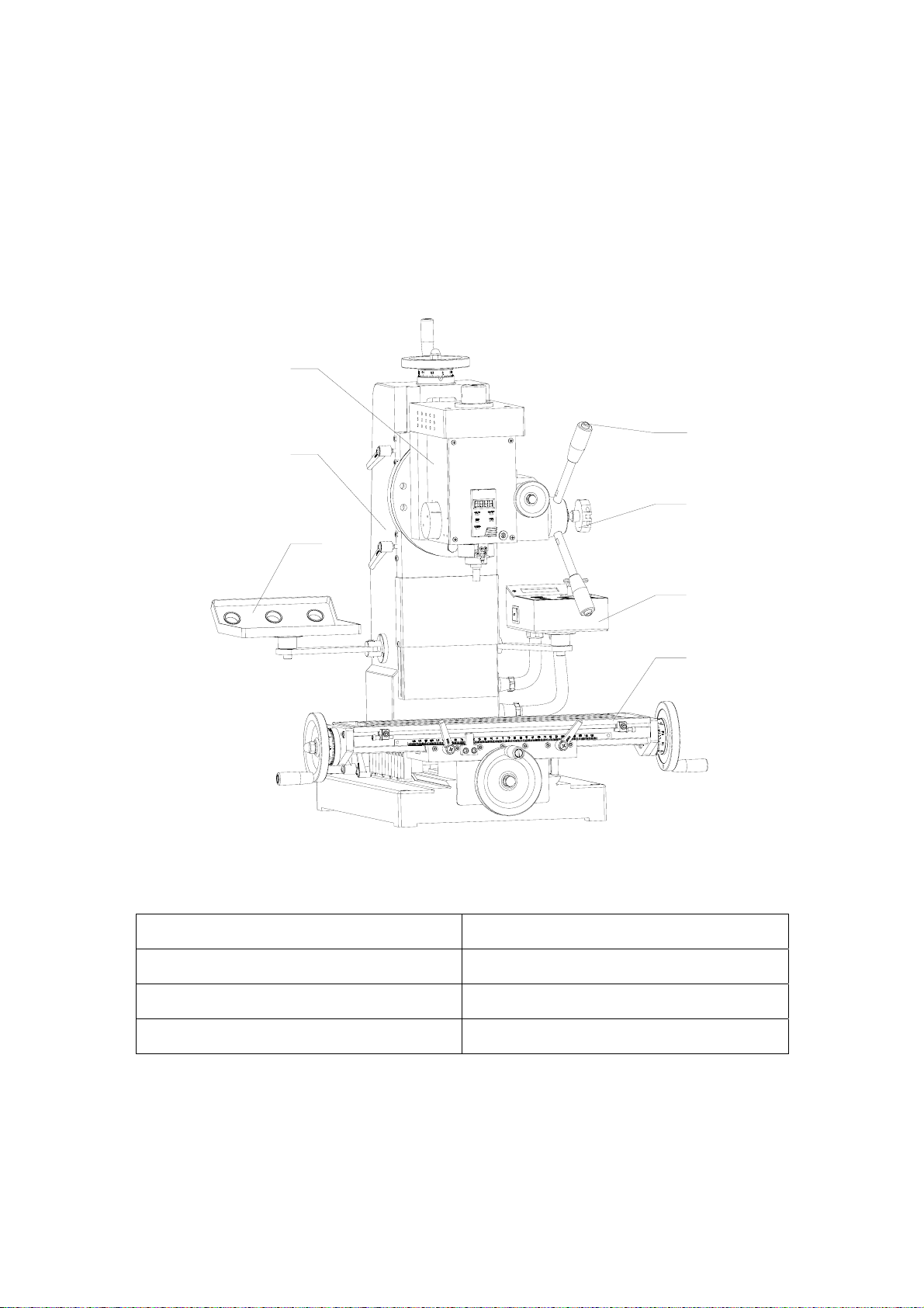
II. XN2 Features
7
6
4
3
5
2
1
1. Worktable
2.Control box 5.Tool holder
3.Handle for spindle locking 6.Column
7. Head stock
4.Handle for forward / backward
6
Page 7

III. Machine Set Up
Fundamental Locating of The Machine
The machine should be fixed on the working table with four Hexagon bolts.
Please install it to an appropriate location in order to demand the precision
requirements of the machine.
The Selection of The Installing Location
(1) The working table should have a flat surface.
(2) Avoid the place with direct sunshine, heavy moisture and dust.
Method of Fundamental Locating
(1) Please drill 4 locating holes on working table, the dimensions should as same as the
holes on the machine’s base .
(Attention: the machine
the exceeding of Y-axis hand wheel will benefit later on.)
(2)Please adjust the machine to horizon and fix the worktable with 4 M10 bolts and nuts.
Before operations
1. Remove all of fixtures which used fixing the machine when you equipped the machine.
2. Check whether the power voltage is suited to the machine.
(See label in front of the machine.)
3. Remove all obstacle which are around the machine.
4. Remove anti-rust protection which were used before you fixed the machine.
5. Check the angle of the pillar and adjust the bolts to see if they are tight enough.
6. Check the chuck, chuck holder and fixing pin on spindle to make sure they are
unloaded.
7. Check the High-Low speed on spindle to see if it sets on right speed.
8. Turn on the machine and check the direction of spindle rotating (clockwise).
9. Operate Longitudinal Axis (Working table), Cross Axis (Saddle seat), Vertical Axis
(Fuselage) to ensure it
10. During the operation , watch out while you’re manipulating the machine.
If there is any unusual situation, stop operating and repair immediately.
’
s position. You had better consider Y-axis hand wheel, because
’
s in normal condition,
7
Page 8

IV. Transmission system
This milling machine transmission system is mainly consisted by: Headstock,
main shaft bearing, main shaft and brushless. The machine is drived by the
brushless motor, it’s work by the motor and main shaft through belt.
The main shaft rotational speed for the direct current power supply through
the stepless speed change knob in the stipulation rotational speed scope. The
main shaft rotational speed is 50 - 2,500 revolution of/minute.
8
Page 9
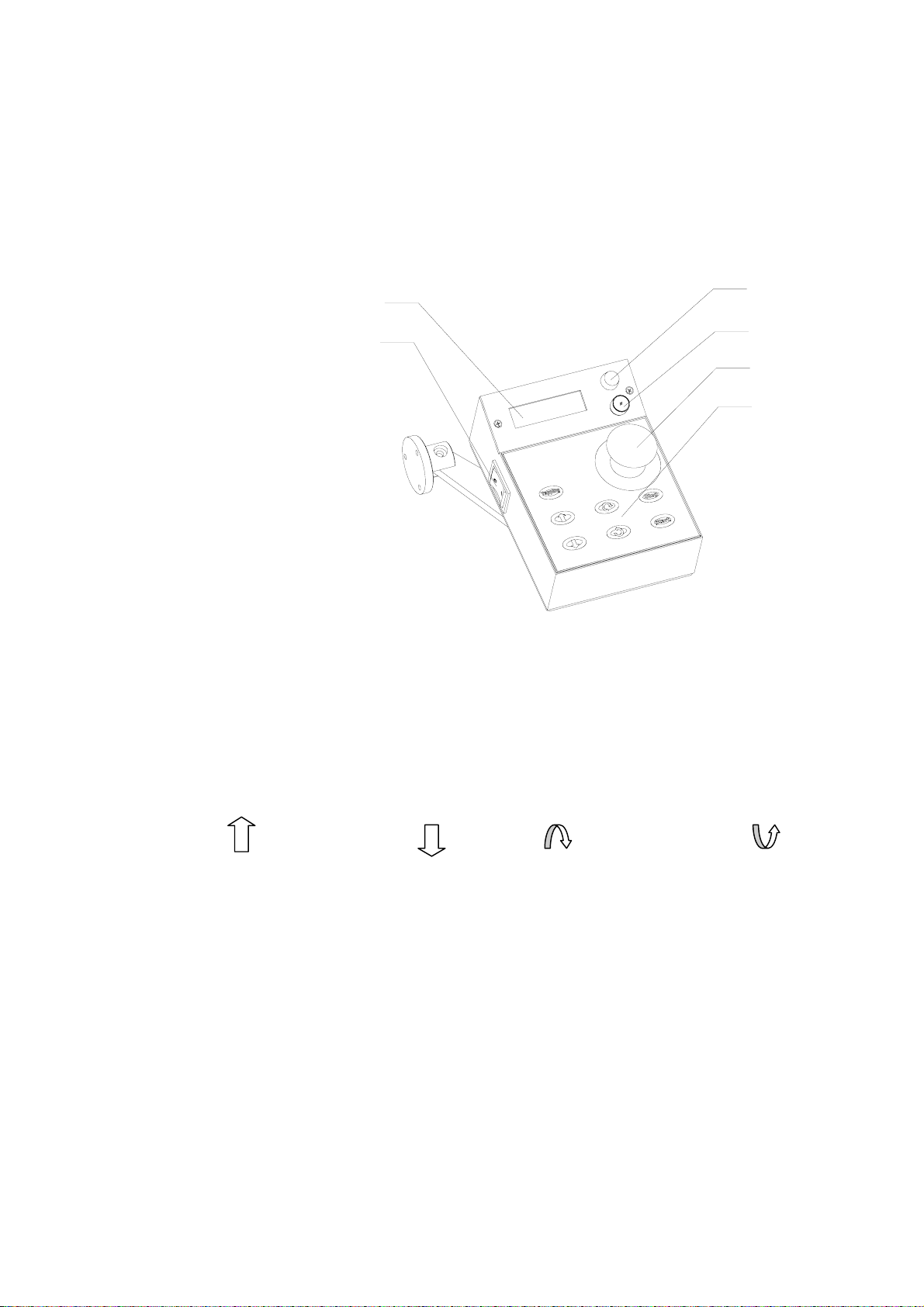
V. Operation and Maintenance
1
5
6
1.Power light
2.Fuse box
2
3
4
3.Emergency stop
4.Control Panel
5.LCD
6.Power switch
Initial start
1. Please be sure put the right fuse in the fuse box. Then be sure the switch is off, open
the emergency stop. Put the plug on, turn on the machine, the power light will be on.
2. When the machine power is on, press the (start) button, the motor is on. Press the
button ( ),speed up, button ( ),speed down. ( )controls the forward.( )
controls the backward. Press(TAPPING), then the screen will show TAPPING,
the speed will slow down. The switch on handle will control the spindle forward and
backward. Press (STOP), then the spindle will stop。
3. The circuit boards on the machine has overload Protection function. Once drilling
and milling are over excessive volume, it will cause machine automatically stop and
showing in the LCD. I will be OK as long as restart the machine again.
9
Page 10
After use
Remove all swarf from the machine and thoroughly clean all surfaces.
Worktable should be dry, and all machined surfaces should be lightly oiled.
Always remove drill bits, cutting tools, and store in a safe place.
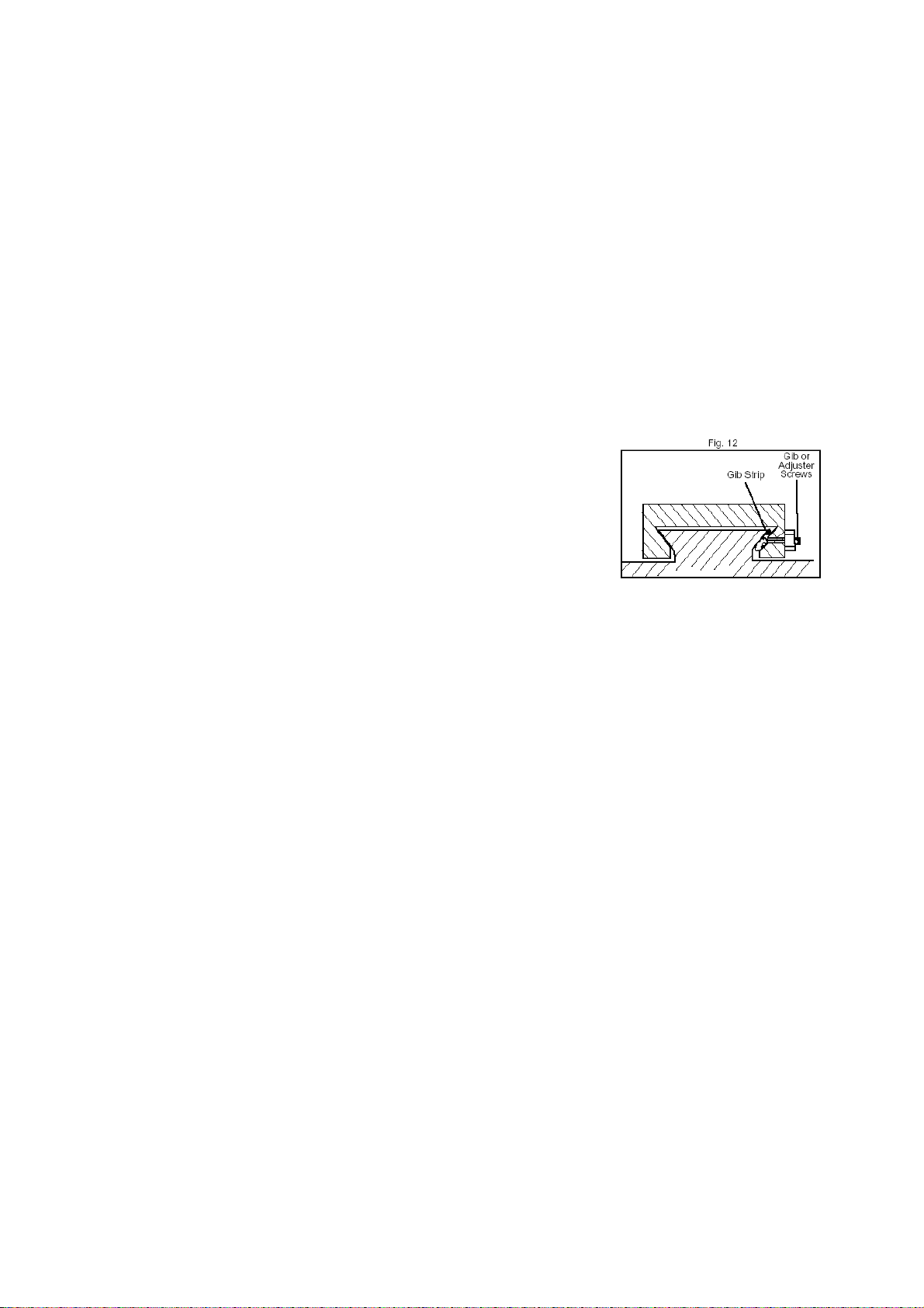
Wedge adjustment
When the machine has operated for a long time, you should adjust the wedge of the
worktable and the position of the saddle.
The needed adjusted position of the wedge, e.g.
1. The cross wedge between the worktable and the saddle.
2. The longitudinal wedge between the saddle and the
base.
The way of the adjustment is, adjusting the screws of wedge till
the handle moving smoothly, then tighten the nuts for locking these screws.
10
Page 11

TROUBLESHOOTING
SYMPTOM POSSIBLE CAUSE CORRECTIVE ACTION
Motor will not start 1. chuck safty cover is
open
2. no power
3. low voltage
4. open circuit in motor or
loose connetions
5. faulty brush
Fuses or circuit breakers
trip
Open
Motor overheats 1. motor overloaded
Cross feed or manual
feed handwheel has
sloppy operation
Cross feed or manual
feed handwheel is hard
to move
1. short circuit in line
cord or plug
2. short circuit in citcuit
board
3. incorrect fuses or
circuit breakers in
power supply
2. air circulation through
the motor restricted
1. gibs are out of
adjusement
2. handwheel is loose
3. lead screw mechanism
wom or out of
adjustment
1. gibs are loaded up with
shavings
2. gibs are too tight
3. bedways are dry
1.close the chuck safety
cover
2.pull out the red
emergency stop switch
button
3.check power supply for
proper voltage
4.inspect all lead
connections on motor for
loose or open connections
5.replace brushes
1. inspect cord or plug for
damaged insulation and
shorted wires and replace
extension cord
2. inspect all connections
on motor for loose or
shorted terminals or wom
insulation and repair
3. install correct fuses or
circuit breakers
1. Reduce load on motor
2. clean out motor to
provide nomal air
circulation
1. tighten gib screw(s)
slamply,and lubricate
bedways
2. tighten handwheel
fasteners
3. tighten any loose
fasteners on lead screw
mechanism
1. remove gibs clean
shavings form bedways
and
dovetails,lubricate,and
readjust gits
2. Loosen gibs screw(s)
slamply,and lubricate
bedways
Lubricate bedways and
handles
11
Page 12

Loud repetitious noise
coming from machine
Machine bogs down
during operation
Tailstock quill will not
feed out of tailstock
Bad surface finish 1. wrong RPM or feed
Can’t remove tapered
tool from quill
The spindle can’t clamp
the end mill
T nuts can’t be fixed 1.the T nuts is broken
1. gears not alighed in
headstock or no
backlash
2. broken gear or bad
bearing
1. excessive depth of cut
2. RPM or feed rate
wrong for cutting
operation
3. dull cutter
4. bad motor or brush
1.quill lock knob is
tightened down
rate
2. dull tooling or poor
tool selection
3. too much play in gibs
1. quill had not retracted
all the way back into
the tailstock
2. debris was not removed
from taper before
insetting into quill
1. choose the wrong end
mill
2. the spindle taper is
wrong
2.the T slot of the
worktable is wrong
1. adjust gears and
establish backlash
2. replace broken gear or
bearing
1. decrease depth of cut
2. refer to RPM feed rate
chart for appropriate
rates
3. sharpen or replace
cutter
4. replace brushes or
motor
1.trun knob
counterclockwise
1. adjust for sppropriate
RPM and feed rate
2. sharpen tooling or
select a better tool for
the intended operation
3. tighten gibs
1. turn the quill
handwheel until it
forces taper out of quill
2. always make sure that
taper surfaces are clean
1.change the end mill
2.check the spindle and
change the right spindle
1.replace the T nuts
2.replace the worktable or
use a whole T slot
12
Page 13
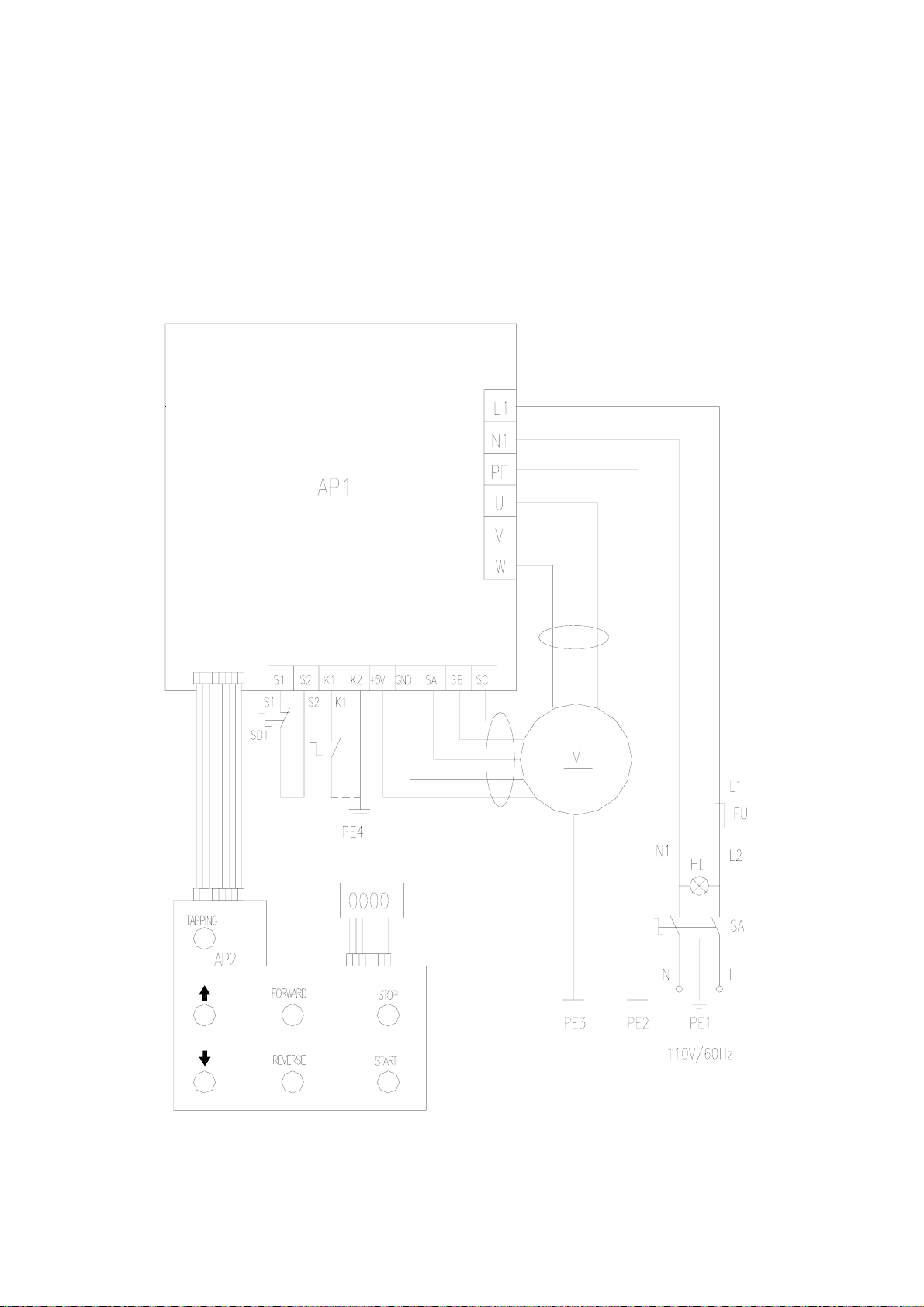
ELECTRICAL CIRCUIT DIAGRAM
13
Page 14
14
Page 15
15
Page 16
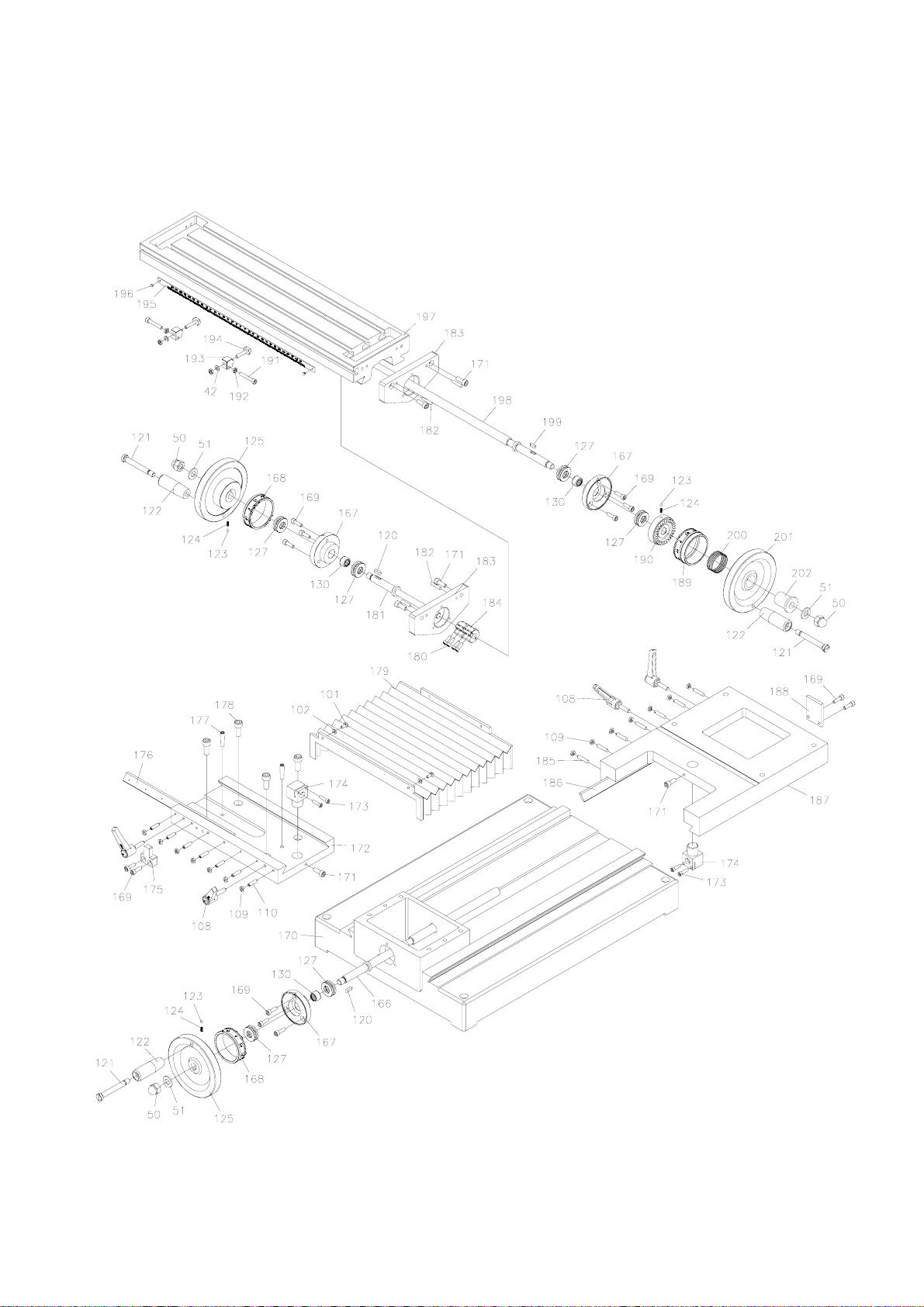
16
Page 17
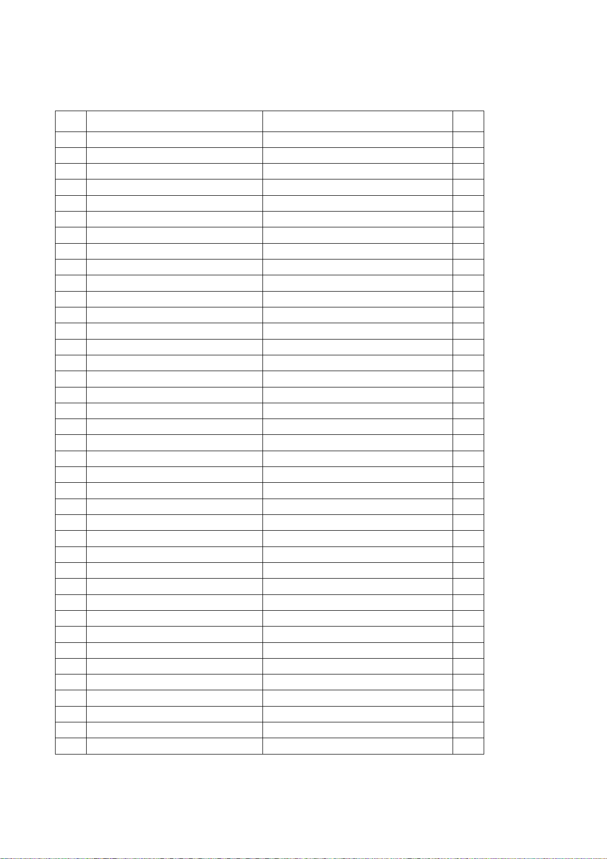
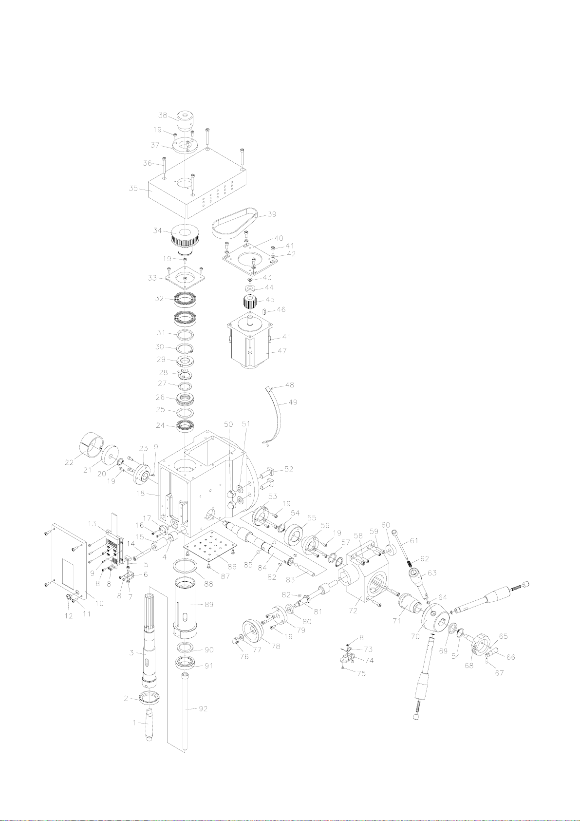
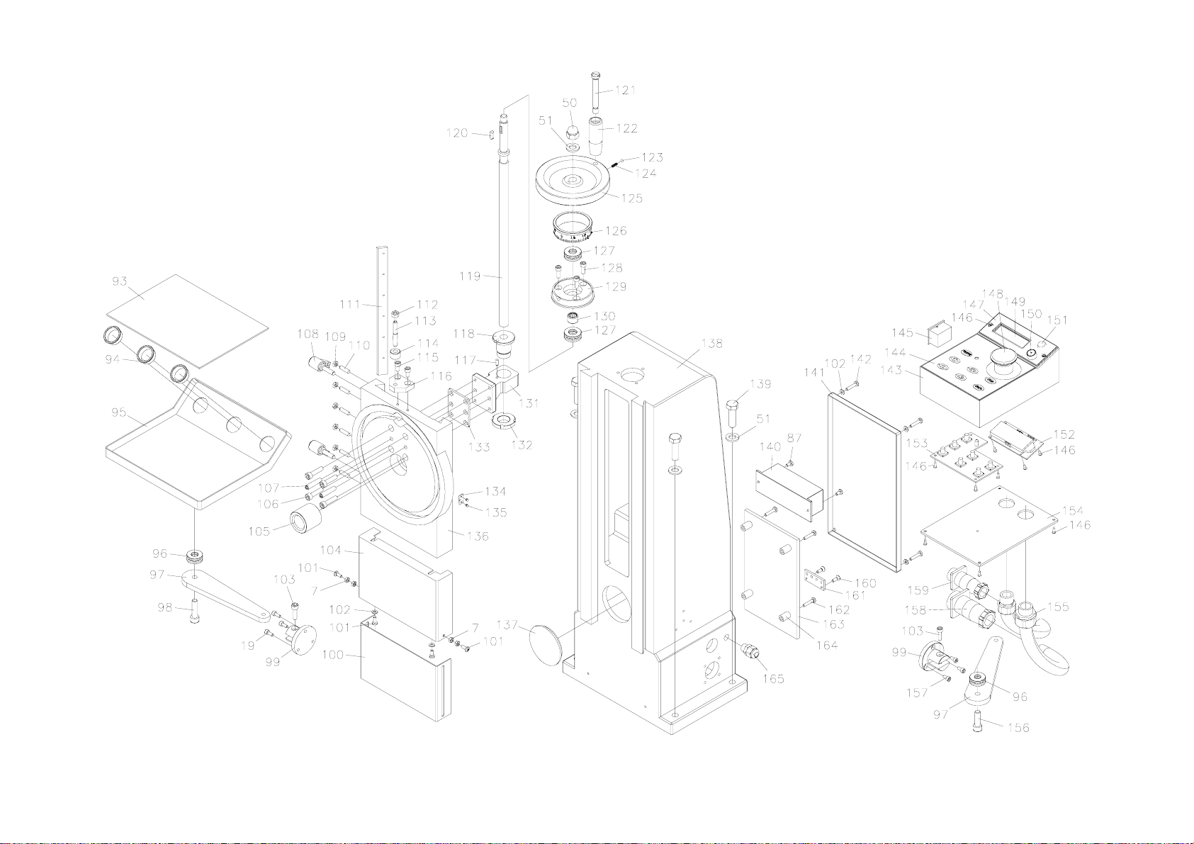
Parts List
No Item No
1 X10222
2 XN20222
3 XN20208
4 XN20224
5 XN20220
6 XN20221
7 GB 6170-86 - M4
8 GB 818-85 - M3 x 6
9 GB 879-86 - 3 x 10
10 XN20213
11 GB 818-85-M4 x 14
12 XN20225
13 GD300
14 GB 70-85 - M6 x 50
15 XN20226
16 GB 819-85 - M3x12
17 XN20217
18 XN20201
19 GB 70-85 - M4 x 10
20 GB 894.1 - 16
21 XN20243
22 X3C0253
23 X3C0252
24 GB 278-89 - 1080905
25 XN20215
26 GB 301-84 - 8105
27 XN20214
28 GB 858-88 - 24 x 34
29 GB 812-88 - M24x1.5
30 GB 894.1 - 35
31 XN20212
32 GB 278-89 - 1080907
33 XN20211
34 XN20210
35 XN20209
36 GB 70-85 - M5 x 40
37 XN20205
38 XN20206
39 HTDM5-320(64 齿)
Description
Taper shank B12
Spindle oil envelop circle
Spindle
Spindle lock sleeve II
Fixup screw
Fixup support
Nut M4
Screw M3*6
Spring pin 3*10
Spindle box cover (front)
Screw M4*14
Small jacket
Display
Screw M6*50
Spindle lock sleeve I
Screw M3*12
Spindle sleeve Orientation shaft
Spindle box cover (front)
Screw M4*10
Spring check ring 16
Check spring
Check spring cover
Left support flange
Ball bearing 1080905
Gasket III
Thrust ball bearing
Gasket II
Lock washer 24*34
Round nut M24*1.5
Spring washer 35
Spindle adjust pad
Ball bearing 1080907
Bearing set flange
Spindle timing pulley
Spindle box Cover
Screw M5*40
Flange
Spindle top cover
Timing belt 64
Qty
1
1
1
1
1
1
6
9
3
1
4
1
1
1
1
2
1
1
22
1
1
1
1
1
1
1
1
1
1
1
1
2
1
1
1
4
1
1
1
17
Page 18

40 XN20202
41 GB 70-85 - M5 x 12
42 GB 97.1-85 - 5
43 GB 819-85 - M6x12
44 XN20204
45 XN20203
46 GB1096-79- 5 x 16
47 500W
48 GB 867-86 - 2 x 8
49 XN20223
50 GB 923-88 - M10
51 GB 95-85 - 10
52 GB8-88 - M10×45
53 XN20241
54 GB 894.1 - 20
55 XN20240
56 XN20239
57 XN20245
58 GB 118-86 - 6 x 20
59 GB 70-85 - M5 x 20
60 XN20229
61 X3C023500
62 GB2089-80 0.7×6×25
63 X3C023600
64 GB 896 - 4
65 Φ4×2
66 X3C0237
67 GB 119-86 - A 3 x 14
68 X3C0238
69 XN20237
70 XN20238
71 XN2023500
72 XN20231
73 X3C0234
74 X3C0243
75 GB 819-85 - M3x6
76 GB 923-88 - M8
77 GB 97.1-85 - 8
78 XN20234
79 XN20233
80 XN20232
81 XN20230
Motor support plate
Screw M5*12
Washer 5
Screw M6*12
Washer IV
Motor timing pulley
Key 5*16
Motor
Rivet 2*8
Angle ruler
Cap nut M10
Washer 10
Square bolt M10*45
Left support flange I
Spring check ring 20
Bevel wheel
Bevel wheel fixup steel sleeve
Washer I
Taper pin 6*20
Screw M5*20
Set sleeve
Control shaft assembly
Compress spring 0.7*6*25
Control shaft assembly
Spring wahser 4
Small magnetism block
Assistant small handle
Round pin 3*14
Worm wheel lock handle
Gear shaft adjust pad
Big handle seat
Guide electricity ring assembly
Worm support box body
Guide electricity bar
Fixup support
Screw M3*6
Cap nut M8
Washer 8
Worm gear handle
Worm flange
Worm adjust pad
Worm
1
8
6
1
1
1
1
1
2
1
8
12
4
1
3
1
1
1
2
4
1
3
3
3
3
1
1
1
1
1
1
1
1
1
1
2
1
1
1
1
1
1
18
Page 19

82 GB1096-79 4 x 8
r
83 XN20236
84 XN20242
85 GB308-89 - 8
86 XN20244
87 GB 818-85 - M4 x 8
88 XN20219
89 XN20216
90 XN20218
91 GB/T 297-94 - 32906
92 XN20207
93 XN21904
94 SB-26
95 XN2190300
96 GB 301-84 - 8100
97 XN21902
98 GB 70-85 - M8 x 30
99 XN21901
100 XN20901
101 GB 818-85 - M4 x 10
102 GB 97.1-85 - 4
103 GB 70-85 - M6 x 20
104 XN20902
105 XN20903
106 GB 70-85 - M6 x 25
107 GB 118-86 - 6 x 30
108 X20218B00
109 GB 6174-86 - M5
110 GB 71-85 - M5 x 20
111 XN20918
112 GB 6170-86 - M6
113 GB 881-86 - 6 x 45
114 XN20906
115 GB 70-85 - M5 x 10
116 XN20905
117 GB 119-86 - A 4 x 10
118 XN20912
119 XN20915
120 GB1096-79 - 4 x 14
121 XN20911
122 X3C1106
123 GB308-89 - 4
key 4*8
Lock small shaft
Gear shaft
Steel ball 8
Motherboard
Screw M4*8
Sleeve limited washe
Spindle sleeve
Spindle sleeve envelop oil circle
Prick ball bearing 32906
Suspend lock shank
Rubber pad
Protect line sleeve
Tray assembly
Thrust ball baring 8100
Connect shank
Screw M8*30
Fixup seat
Z axis cover (II)
Screw M4*10
Washer 4
Screw M6*20
Rubber pad
Set shank
Screw M6*25
Screw taper pin 6*30
Lock handle
Nut M5
Set screw M5*20
Z axis wedge
Nut M6
Taper pin 6*45
Quit sleeve
Screw M5*10
Reposition fix block
Column pin
Z axis nut
Z axis leadscrew
Key 4*14
Handle sleeve screw
Handle sleeve
Ball 4
3
1
1
3
1
6
1
1
1
1
1
1
3
1
2
2
1
2
1
6
8
2
1
1
4
2
6
20
13
1
1
1
1
2
1
1
1
1
3
4
4
4
19
Page 20

124 GBT2089-1994 0.5×4×12
125 XN20907
126 XN20908
127 GB 301-84 - 8101
128 GB 70-85 - M5 x 14
129 XN20909
130 GB 290-89 HK121610
131 XN20913
132 GB 812-88 - M20x1.5
133 XN20904
134 X21108
135 GB 867-86 - 2 x 2
136 XN20914
137 XN20919
138 XN20917
139 GB 5781-86 - M10x35
140 FC-03HB
141 XN20916
142 GB 818-85 - M4 x 20
143 XN21801
144 XN22501
145 HY12-9
146 GB 846-85 ST2.9x9.5
147 XN21802
148 Y090
149 XN21805
150 HJMF527
151 ZD10
152
153 FC350JYA
154 XN2180300
155 G3/8 软管接头
156 GB 70-85 - M8 x 25
157 GB 70-85 - M4 x 8
158 16 芯航空接头
159 4 芯航空接头
160 GB 819-85 - M4x12
161 XN21804
162 GB 818-85 - M4 x 20
163 XMT-W1150
164 XN21806
165 M12 拉不脱
Compress 0.5*4*12
Handlewheel ( I )
Scale ring
Thrust ball bearing 8101
Screw M5*14
Z axis bearing seat
Bearing HK121610
Z axis nut seat
Notch round nut
Adjust washer
Zero label
Rivet 2*2
Z axis slide plate
Protect cover
Fuselage
Bolt M10*35
Fliter
Back cover
Scew M4*20
Control box body
Control box body
Switch
Screw ST2.9*9.5
Support plate
Emergency buttom
Plastic glass
Fuse seat
Green light (big)
Display
Buttom plate
Fix assembly
Tube connect
Screw M8*25
Screw M4*8
Connect
Connect
Screw M4*12
Grounding line
Screw M4*20
PC Board
Nylon mat
Draw lock
4
3
1
8
3
1
4
1
1
1
1
2
1
1
1
4
1
1
4
1
1
1
14
1
1
1
1
1
1
1
1
1
1
3
1
1
2
1
4
1
4
1
20
Page 21

166 XN21113
167 XN21117
168 XN21105
169 GB 70-85 - M5 x 16
170 XN21101
171 GB 70-85 - M6 x 16
172 XN21111
173 GB 70-85 - M4 x 16
174 XN21114
175 XN21112
176 XN21108
177 GB 118-86 - 6 x 28
178 GB 70-85 - M8 x 20
179 XN21116
180 GB 70-85 - M4 x 12
181 XN21118
182 GB 117-86 - A 4 x 22
183 XN21104
184 XN21119
185 GB 71-85 - M5 x 25
186 XN21110
187 XN21103
188 XN21106
189 XN21124
190 XN21123
191 GB 70-85 - M5 x 30
192 GB 6172-86 - M5
193 XN21115
194 XN21107
195 X21128A
196 GB 867-86 - 2.5 x 6
197 XN21109
198 XN21102
199 GB1096-79- 4 x 12
200 XN21120
201 XN21122
202 XN21121
Y axis leadscrew
Y axis bearing seat
Scale ring (I)
Screw M5*16
Base
Screw M6*16
Saddle
Screw M4*16
Copper nut
Fixup bump block
X axis wedge
Round pin 6*28
Screw M8*20
Y axis guide protect cover
Screw M4*12
Leadscrew shaft
Round taper pin 4*22
Bearing seat fix plate
Connect shaft organ
Set screw M5*25
Y axis wedge
Y axis slide plate
Limited block
Scale ring ( II )
Clutch
Screw M5*30
Nut M5
Movement support
T bolt
Rule
Revit 2.5*6
Worktable
X-axis leadscrew
Key 4*12
Compress spring
Handlewheel (II)
Lock sleeve
1
3
2
13
1
6
1
4
2
1
1
2
4
1
4
1
4
2
1
7
1
1
1
1
1
2
4
2
2
1
2
1
1
1
1
1
1
21
 Loading...