

Page 1
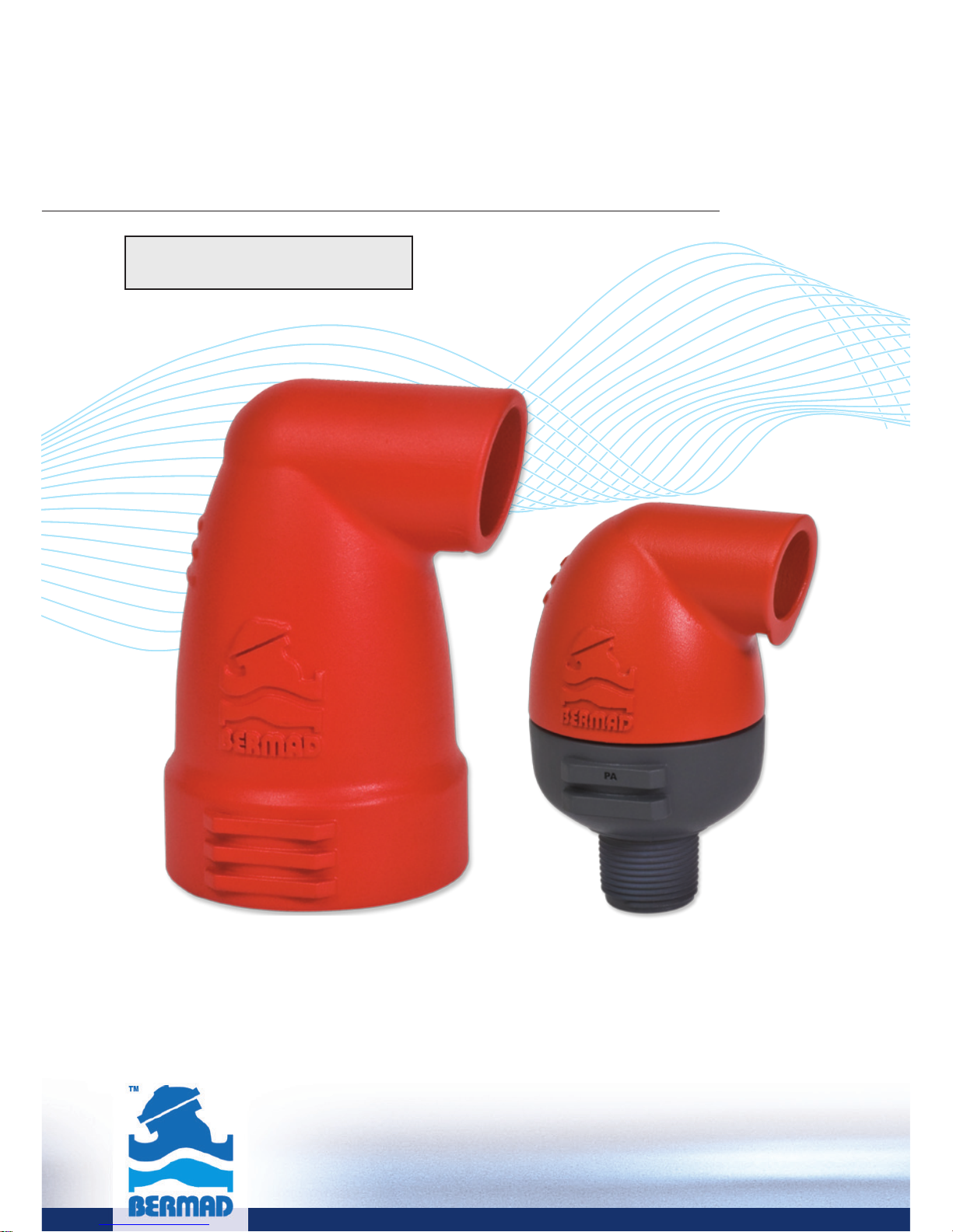
Installation, Operation and
Maintenance Manual (IOM)
Kinetic (Air / Vacuum)
Air Valve
Model K10
Page 2

Page 3

1
Table of Contents
General ......................................................................... Page 2
Safety ........................................................................... Page 2
Operational Data ........................................................... Page 3
Materials and Connections ............................................ Page 3
K10 (1", ¾") Parts List ................................................... Page 4
K10 (2") Parts List ......................................................... Page 5
Unpacking and post shipment inspection ...................... Page 6
Site Preparation ............................................................ Page 6
Installation...................................................................... Page 7
Start-up and first operation ........................................... Page 9
Operation and Maintenance .......................................... Page 9
Inspection ..................................................................... Page 10
Troubleshooting ............................................................ Page 11
Disassembling and Reassembling the valve (1", ¾")......... Page 12
Disassembling and Reassembling the valve (2") ............ Page 14
Page 4

2
BERMAD K10 is a high quality Kinetic air valve for a
variety of irrigation networks and operating conditions.
It evacuates air during pipeline filling and enables large
volume air intake in the event of network draining.
With its advanced aerodynamic design and Kinetic
orifice, this valve provides excellent protection against
vacuum formation with improved sealing at low
pressure.
This document is the Installation, Operation and
Maintenance manual (IOM) of this valve; it describes the
procedures required for proper usage of the valve.
Since air valves operate in pressurized water networks
and sewage systems you are required to carefully read
this manual before using the valve. Handle the valve
with care and make sure to comply with all the relevant
required safety instructions and standards, general and
local.
Safety
General
Page 5

3
Pressure rating ISO PN10, ANSI / ASME 150
Operating pressure range 0.1-10 bar / 1.5-150 psi
Operating temperature Water up to 60°C / 140˚
F
Operational Data
Materials and Connections
Body material Glass-reinforced plastic
Inlet diameter DN20, DN25, DN50 (¾", 1" 2")
Connections Threaded Male BSPT,
NPT for ¾", 1" (DN20, DN25)
Threaded Female BSP, NPT for 2" (DN50)
Outlet types Sideways
Page 6
4
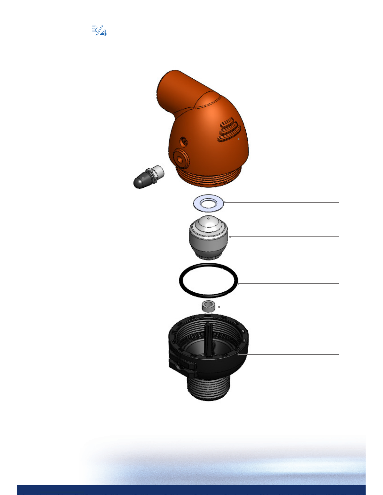
Test Point (#7)
Body (#2)
Kinetic Seal (#4)
Float (#3)
O-Ring (#5)
Spacer (#6)
Base (#1)
K10 1", ¾" Parts List
Page 7
5
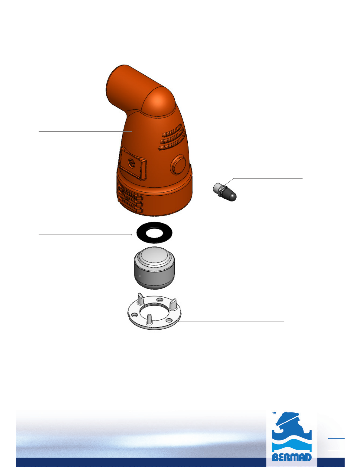
Stopper Disc (#2)
Test Point (#7)
Body (#1)
Kinetic Seal (#4)
Float (#3)
K10 2", Parts List
Page 8

6
Unpacking and post shipment inspection
■
Make sure that till the actual installation the valve
remains dry and clean in its original package.
■
Unpack the valve and make sure that all the wrapping
materials are removed.
■
Before installation it is necessary to inspect that no
damage to the valve had occurred during shipment;
do not install a damaged valve!
■
Verify that the valve to be installed meets the design
specifications of the specific installation site;
take extra care and make sure that the expected
system pressure complies with the pressure rating of
the valve.
■
Air Valves located above ground should be protected
from freezing, contamination and vandalism.
■
If the valve is to be installed in a pit, make sure that
the pit has proper drainage and sufficient dimensions
for servicing the valve.
■
Flush the pipeline prior to the Air Valve installation in
order to prevent damage to the valve internals due
to large debris carried by the water during startup.
Site Preparation
Page 9

7
■
Main irrigation networks - Air relief and vacuum
prevention downstream of pumps, along supply lines
and at elevations in main irrigation networks.
■
Irrigation control head – Air relief and vacuum
prevention at filtration and fertilization stations.
■
Infield systems – Prevention of vacuum formation.
■
Landscape irrigation – Prevention of vacuum formation.
Typical Applications
Installation
■
The K10 air valve is not to be used in systems
containing high suspended solids; consider
selecting other Bermad Air Valve models for
such water type.
Page 10
8
■
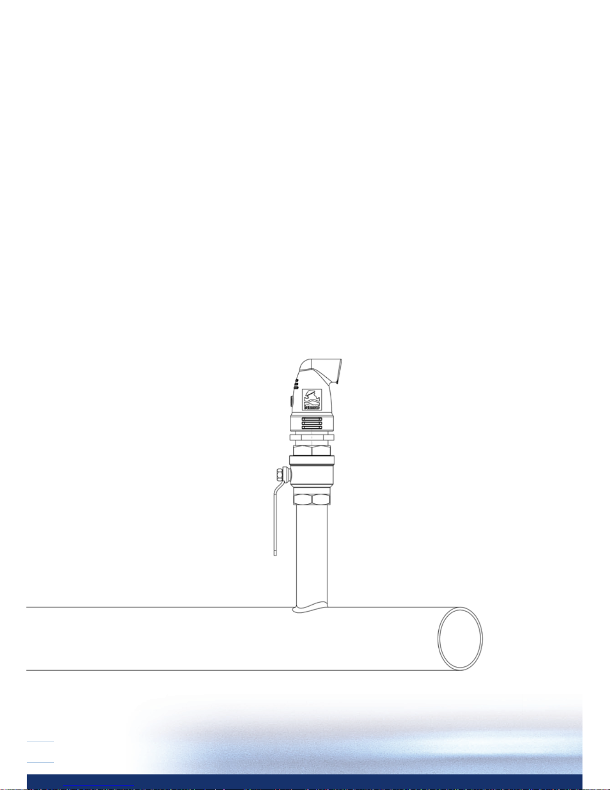
Install the Air Valve as close as possible to the pipe,
at a high point of its circumference, in vertical position
(within 5 degrees of vertical alignment) and with its inlet
facing down.
■
The diameter of the pipe connecting the Air Valve
with the pipeline should be at least equal to the Air
Valve inlet diameter.
■
Install a shutoff valve between the air valve and
the pipeline for allowing easy inspection and
maintenance.
Installation instructions
Page 11

9
Operation and Maintenance
Principles of Operation
Pipeline Filling
During the filling process of a pipeline, high air flow is
forced out through the kinetic orifice of the air valve.
Once water enters the valve’s chamber, the float buoyed
upward causes the kinetic orifice to close. The unique
aerodynamic structure of the valve body and float
ensures that the float cannot be closed before water
reaches the valve.
Pressurized Operation
During pressurized operation of the pipeline the kinetic
orifice remains closed.
Start-up and first operation
■
Open the shutoff valve and verify that the Air Valve
connections are not leaking; if needed follow the
troubleshooting instruction section of this document.
Please note that at the first time the valve is filled up
some water may exit through its outlet port.
■
Prevent water hammer during startup and pipeline
filling; maintain the velocity lower than 0.5m/sec
(1.6 feet/sec).
Page 12

10
Pipeline Draining
When a pipeline is drained, a negative differential
pressure is created causing atmospheric air to push the
float down. The kinetic orifice stays open and air enters
the valve chamber, preventing vacuum formation in the
pipeline.
Inspection
The valve does not require any specific maintenance,
however a periodical inspection of the seals and flushing
of the valve are recommended for removing debris
and foreign objects. The valve’s flushing and cleaning
frequency depends on water quality and dirt-load.
Page 13

11
Symptom Action
Leakage at the
inlet connection
Tighten the valve connection, use
thread sealant. Check whether any
part/seal is damaged.
Leakage at
the valve cover
Tighten the valve’s cover (¾", 1)
Check the orices area for leaks.
Leakage at
the valve’s
outlet
Flush the valve to remove debris,
dissemble and inspect the valve’s
orice, oat and seal.
Remove any foreign objects, check
and replace any damaged part.
Valve does not
relief air or
allow air intake
Verify that the operating pressure
does not exceed the valve’s rated
working pressure.
Check and remove foreign objects.
Clean the valve’s internal parts,
replace if necessary.
Consult Bermad if the symptom
continues.
Troubleshooting
Page 14

12
Disassembling and Reassembling the valve 1", ¾"
Disassembling the K10 ¾", 1” valve
1. Release the valve’s body (Part #2) by turning it
counterclockwise, un-screw and remove it from the
valve’s Base (Part #1). Make sure that the valve parts,
seated within the cover do not fall out of the cover.
2. Inspect the valve basis O-ring (Part #5) and if
necessary replace it with a new one. Make sure that
the new O-ring is seated correctly in its designated
groove in the valve’s basis.
3. Pull the float assembly (Part #3) out of the conduit pin
and remove it out of the valve-cover.
4. Inspect the float’s Kinetic Seal (Part #4) and the float
(Part #3) for wear and tear. If necessary replace the
old parts.
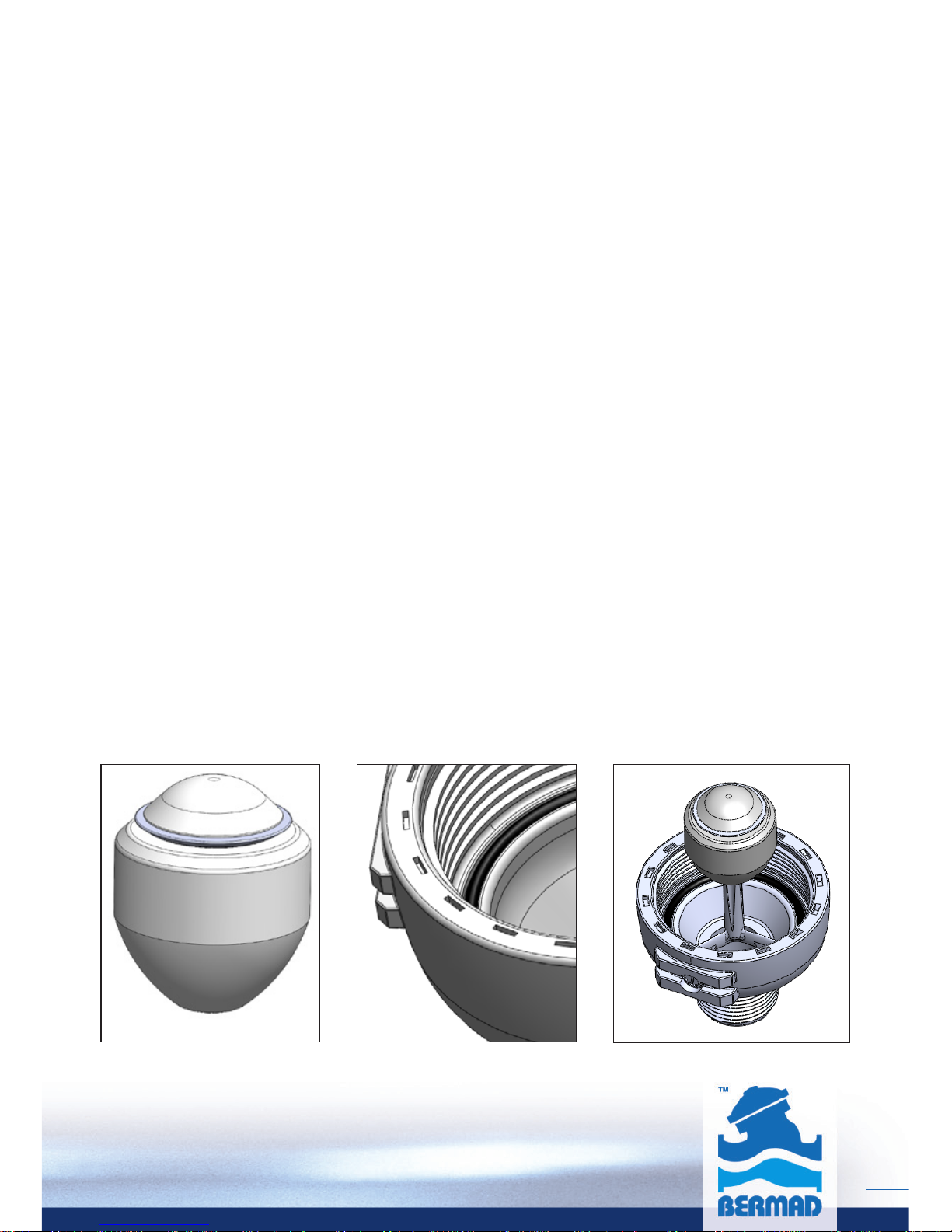
5. Replacing the Kinetic Seal:
a. Remove the old Seal
b. Wet the new Kinetic Seal (Part #4) with clean water
c. Install the kinetic seal (Part #4) on the Float
(Part #3) with its raised edges side facing upward.
See Fig. A
Page 15
13
Reassembling the K10 ¾", 1” valve
1. Insert the float with the Kinetic Seal on the conduit
pin to its place within the valve-cover; make sure that
the float freely falls downwards along the conduit pin.
2. Make sure that the valve’s basis O-ring (Part #5) is fully
inserted to its groove within the basis.
See Fig. B
3. Put the Spacer and the Float on the shaft located in
the center of the base.
Make sure that the Float is located in the lower part
See Fig. C
4. Reassemble the valve body to the valve basis by
screwing it on the basis thread. Tighten the cover.
5. The valve is reassembled, perform a complete start up
procedure as described above.
Fig. CFig. BFig. A
Page 16

14
Disassembling and Reassembling the valve K10-2"
Disassembling the K10 2” valve
1. Pull the Stopper Disc (Part #2) out of the valve-cover
then pull out the float assembly (Part #3).
2. Inspect the float’s Kinetic Seal (Part #4) and the Float
(Part #3) for wear and tear. If necessary replace the
old parts.
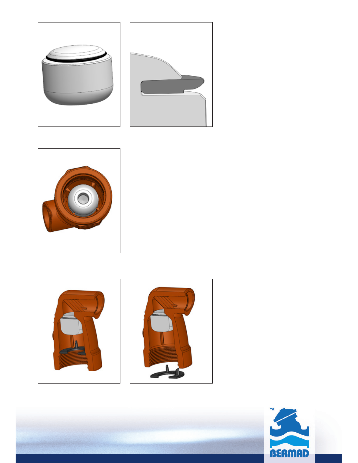
3. Replacing the Kinetic Seal:
a. Remove the old seal
b. Wet the new Kinetic Seal (Part #4) with clean water
c. Install the Kinetic Seal (Part #4) on the Float
(Part #3) with its raised edges side facing upward.
See Fig. M
Reassembling the K10 2” valve
1. Insert the float with the Kinetic Seal to its place within
the valve-cover while the float-bore facing downward.
See Fig. N
2. Insert the Stopper Disc (Part #2) to its place in the
valve-cover with the snap legs facing the float. Use
the special locking tool to push the Stopper Disc to
its place.
See Fig. P
3. The valve is reassembled, perform a compete
start up procedure as described above.
Page 17
15
Fig. N
Fig. P
Fig. M
Page 18

info@bermad.com • www.bermad.com
The information herein is subject to change without notice. BERMAD shall not be held liable for
any errors. All rights reserved. © Copyright by BERMAD.
[email protected] • www.bermad.com
PIAXE12-K10
 Loading...