

Page 1
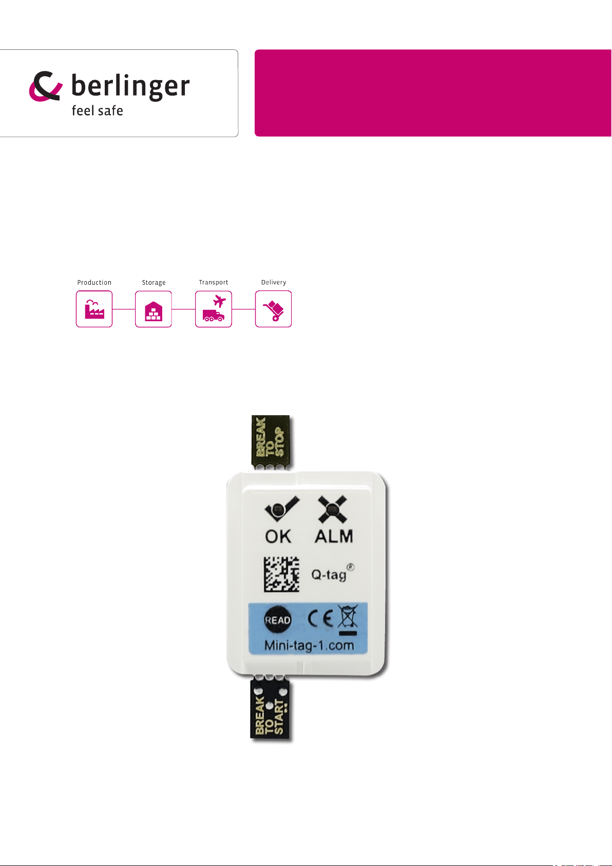
Berlinger Mini-tag
User manual
Multi-alarm temperature indicator
®
20160715_Release_1.1
Page 2

Inhaltsverzeichnis
1) Foreword / introduction ..........................................................................3
2) Before commissioning............................................................................3
2.1) Delivery status ............................................................................................................. 3
2.2) Quality test ................................................................................................................... 3
2.3) Device Explanation ...................................................................................................... 3
2.4) Alarm programming ..................................................................................................... 3
3) Activation .................................................................................................4
3.1) Activation process ........................................................................................................ 4
Activation option 1: ............................................................................................................ 4
By breaking the START break-o tab (standard) ................................................................ 4
Activation option 2: ............................................................................................................. 4
By pressing the READ button ............................................................................................. 4
3.2) Start delay (optional) .................................................................................................... 4
3.3) Correct positioning ....................................................................................................... 4
4) LED sequence during measurement operation ...........................................5
4.3) Option 1: ...................................................................................................................... 5
Status display only on query ............................................................................................... 5
4.2) Option 2: ..................................................................................................................... 5
Continuous status display ................................................................................................... 5
5) LEDs: Explanation of the blink sequences ...........................................6
6) LEDs: Alarm identication (optional) ....................................................7
7) Ending of the measurement operation ..................................................8
7.1) De-activation option 1: ................................................................................................. 8
De-activation by breaking the STOP break-o tab (standard) ............................................ 8
7.2) De-activation option 2: ................................................................................................ 8
De-activation by pressing the READ button ........................................................................ 8
7.3) De-activation option 3: ................................................................................................. 8
No stop function .................................................................................................................. 8
8) LED sequence after stop conrmation .................................................9
8.1) Option 1: ..................................................................................................................... 9
Display of the device status only on query .......................................................................... 9
8.2) Option 2: ..................................................................................................................... 9
Continuous display of the device status .............................................................................. 9
9) Assistance with problems ......................................................................9
10) Technical specications .....................................................................10
11) Important Information .........................................................................10
11.1) Liability ..................................................................................................................... 10
11.2) Battery ...................................................................................................................... 10
11.3) Useful life ................................................................................................................. 10
12) Contact .................................................................................................10
2
Page 3
1) Foreword / introduction
The Berlinger Mini-tag® is a very small but extremly powerful temperature-monitoring device. It
measures the ambient temperature precisely and continuously. There can be up to 3 alarm limits
programmed and monitored individually. If a temperature limit is exceeded or undershot, an alarm will
be immediately triggered and visually displayed via the LED indicators on the device (OK or ALARM
icon).
2) Before commissioning
2.1) Delivery status
®
The Berlinger Mini-tag
have been factory pre-programmed. Currently, no temperature data is being recorded. The Berlinger
®
Mini-tag
must be started before the measurement mode starts. (see Chapter 3: Activation)
2.2) Quality test
The device has passed the necessary high-quality controls at the manufacturer. For the avoidance of
transport damage, we recommend checking the following points before using the Berlinger Mini-tag
• The LED displays on the front of the panel are not blinking
• All components as described under Point "2.3 Device Explanation" are available.
is delivered in inactive mode. Any customer-specic alarm congurations
®
:
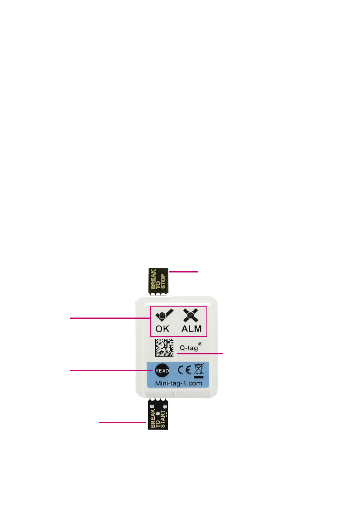
2.3) Device Explanation
LEDs
(green = OK / red = ALARM x)
READ button
(for status query, optional to
start / stop)
START break o tab
STOP break o tab
2D Code
contains the following
information:
• CID
• Customer
• Expiry date
• Serial number:
Example:
999C22E1503S1234567
2.4) Alarm programming
Three dierent alarm limits can be programmed. Alarm limits can be dened with temperature and
time (cumulative or single event). The alarm limits are programmed at the factory and cannot be
changed upon receipt of the device.
3
Page 4
3) Activation
3.1) Activation process
The Berlinger Mini-tag® temperature indicator starts the temperature-measuring operation by
breaking o of the START break-o tab or by pressing and holiding the READ button for at least 3
seconds. The desired method of activation is dened upon ordering.
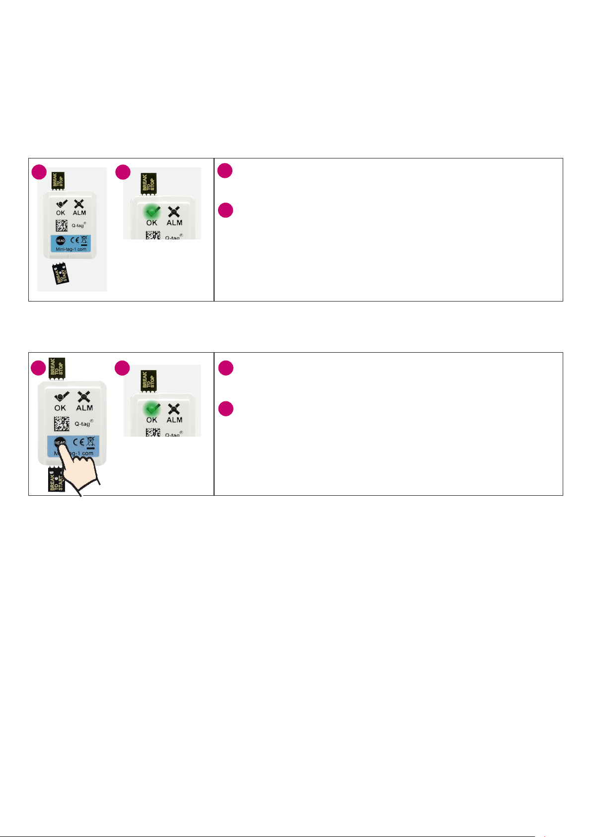
Activation option 1:
By breaking the START break-o tab (standard)
1
1
2
Start
conrmation:
green blinks
10 times
Activation option 2:
By pressing the READ button
The device is started by the START break-o tab (the tab is
labelled BREAK TO START) being completely broken o.
2
The successful activation is conrmed by the green LED
indicator (OK) blinking 10 times.
(see Chapter 5: LEDs: Explanation of the “start conrmation” blink
sequences)
1
Note: Once the device is activated, the Berlinger Mini-tag® immediately monitors the programmed
temperature limits and registers any violation of a temperature limit.
2
Start
conrmation:
green blinks
10 times
The device is started by pressing the READ button (with the
1
edge of a ngernail) for at least 3 seconds.
2
The successful activation is conrmed by the green LED
indicator (OK) blinking 10 times.
(see Chapter 5: LEDs: Explanation of the “start conrmation” blink
sequences)
3.2) Start delay (optional)
If a start delay has been congured at the factory, the countdown starts immediately after activation of
the device. The LEDs do not blink during the countdown / start delay. No status queries are possible.
After completion of the countdown / start delay, the green LED blinks on the OK symbol 2 times
(see Chapter 5: LEDs: Explanation of the “start measurement operation after expiry of the start delay” blink
sequence).
The device is immediately in active mode and monitors the temperature.
3.3) Correct positioning
The activated temperature indicator must be placed immediately and as close as possible to the
monitored products in order to obtain the most accurate temperature data of the goods to be
monitored. This is an important prerequisite for the temperature measurement to be meaningful.
Note: We recommend that devices without a programmed start delay be preconditioned for 30
minutes prior to activation. Any false measurements on the start of the device can thus be avoided.
4
Page 5

4) LED sequence during measurement operation
4.3) Option 1:
Status display only on query
The LEDs only light up when a request is performed. By pressing the READ button once, the status
request / alarm identication can be performed at any time. Thus, the status / alarm identication is
displayed again every 10 seconds for a duration of one minute
explanation of blink sequences and alarm ID)
/ alarm identication can be displayed again by pressing the READ button once more.
. Thereafter, the LED indicator will stop blinking. The status
4.2) Option 2:
Continuous status display
The LEDs blink continuously, green for OK or red for ALARM. Thus, the status / alarm identication
is displayed by regularly blinking according to optional programmed intervals of 15, 30 or 60 seconds.
(see Chapters 5 and 6: LEDs explanation of the blink sequences and alarm identication)
Attention: Due to increased battery usage, this option reduces the operating time of the device!
The continuous display is terminated when the battery capacity is low. The query is still possible by
pressing the READ button until the battery life has expired.
(see Chapters 5 and 6: LED indicators
5
Page 6
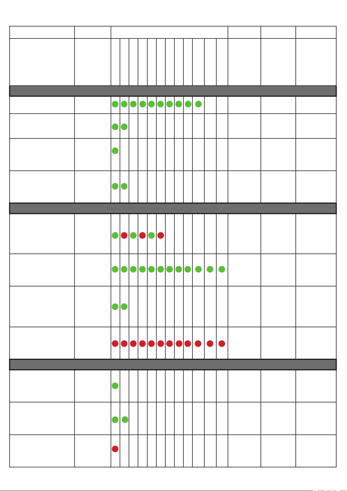
5) LEDs: Explanation of the blink sequences
Anzahl blinken
Description
Possible displays during the measurement operation
Start conrmation Blink green
10 times
Start measurement
operation after expiry
of the start delay
Normal operation
(without alarm)
Normal operation
and duration reserve
* reached warning
Blink green 2
times
Blink green 1
time
Blink green 2
times
1 2 3 4 5 6 7 8 9 10 11 12 Time
between
blink
interval
1 seconds - -
(0.5
seconds)
- Every 10
(0.5
seconds)
Possible displays during the stop process
Query
with
READ
button
- -
seconds,
repeating 6
times
Every 10
seconds
repeating 6
times
Repeat
every x
seconds
during
long-term
display
15, 30 or 60
seconds
15, 30 or 60
seconds
Stop conrmation The green
and red LED
blink each 3
times alternatively
Status after stop
conrmation without
alarm
Status after stop
conrmation without
alarm but warning
that duration reserve
* reached
Status after stop
conrmation with
alarm (without alarm
identication)
Status display
without alarm
Status display
without alarm but
warning that duration
reserve * reached
Status display with
alarm (without alarm
identication)
Blink green 1
time every 10
seconds for 2
minutes
Blink green 2
times every
10 seconds
for 2 minutes
Blink red 1
time every 10
seconds for 2
minutes
Blink green 1
time
Blink green 2
times
Blink red 1
time
1 second - -
10 seconds - -
(0.5
seconds)
10 seconds - -
Possible displays after stop process concluded
- Every 10
(0.5
seconds)
- Every 10
- -
seconds
repeating 6
times
Every 10
seconds
repeating 6
times
seconds
repeating 6
times
15, 30 or 60
seconds
15, 30 or 60
seconds
15, 30 or 60
seconds
6
Page 7
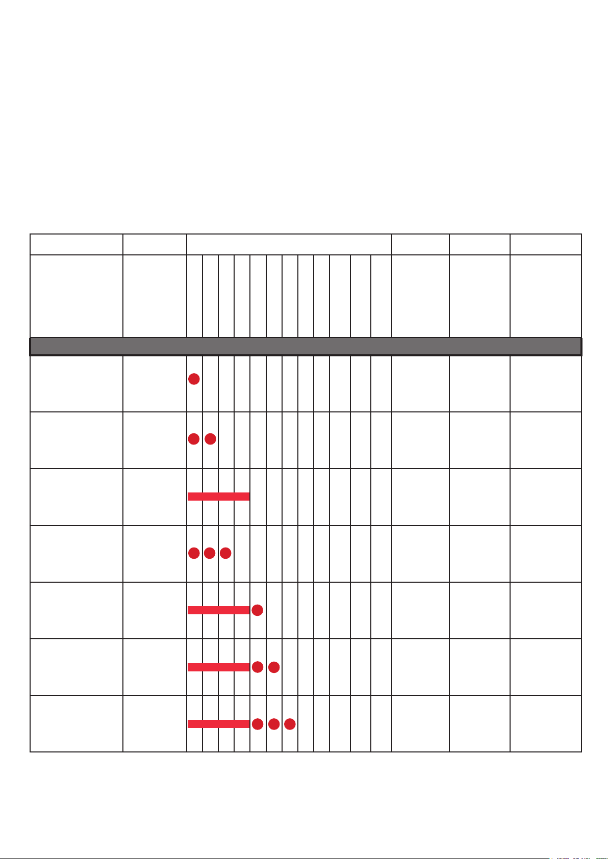
*Duration reserve (optional)
With cumulative alarm events, it is also possible to set a duration reserve for the cumulative alarms.
This serves as a warning, at least on a cumulative alarm, that the duration of the remaining alarm
time is less than the programmed duration reserve.
Example:
Cumulative alarm at >8 °C for 60 minutes with a duration reserve of 10 minutes.
If the temperature accumulated for 50 minutes is over +8 °C, the device will recognise that the
duration reserve is reached. This is indicated with the green LED blinking 2 times, instead of 1 time
for display of normal operation without alarm. After another 10 minutes in the alarm temperature
range, the alarm is triggered and the red LED blinks.
6) LEDs: Alarm identication (optional)
Anzahl blinken
Description
Possible displays during the measurement operation and after completion of the stopping process
AL1 Blink red 1
time
AL2 Blink red 2
times
AL3 Light red 1
time for 2
seconds
AL1 + AL2 Blink red 3
times
AL1 + AL3 Light red 1
time for 2
seconds and
blink 1 time
AL2 + AL3 Light red 1
time for 2
seconds and
blink 2 times
AL1 + AL2 + AL3 Light red 1
time for 2
seconds and
blink 3 times
1 2 3 4 5 6 7 8 9 10 11 12 Time
between
blink
interval
- Every 10
- Every 10
- Every 10
- Every 10
- Every 10
- Every 10
- Every 10
Query
with
READ
button
seconds
repeating 6
times
seconds
repeating 6
times
seconds
repeating 6
times
seconds
repeating 6
times
seconds
repeating 6
times
seconds
repeating 6
times
seconds
repeating 6
times
Repeat
every x
seconds
during
long-term
display
15, 30 or 60
seconds
15, 30 or 60
seconds
15, 30 or 60
seconds
15, 30 or 60
seconds
15, 30 or 60
seconds
15, 30 or 60
seconds
15s, 30s oder
60s
7
Page 8
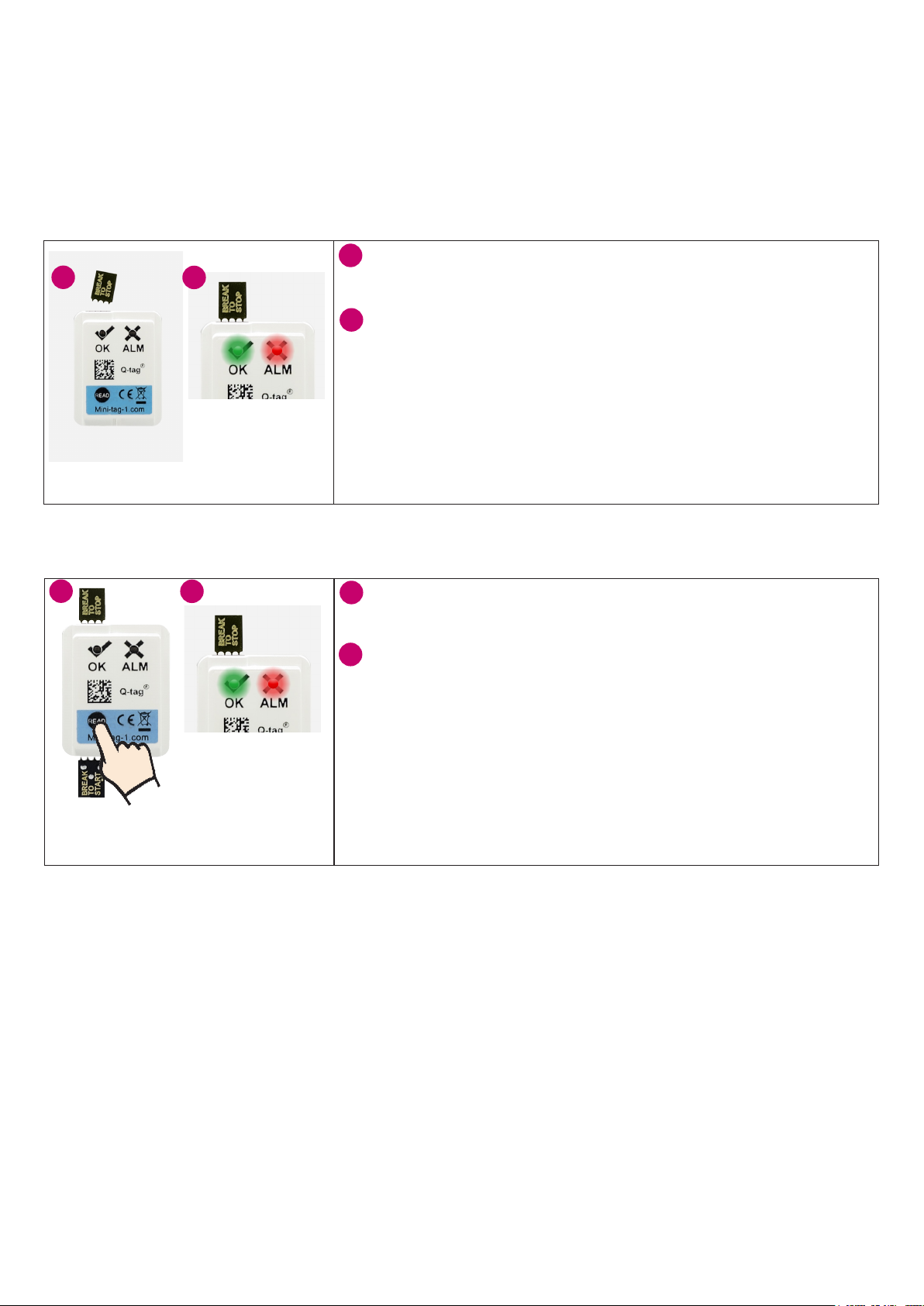
7) Ending of the measurement operation
The measurement operation of the Berlinger Mini-tag® temperature indicator can be stopped by either
breaking o the STOP break-o tab or by pressing and holding the READ button for 6 or 10 seconds.
The desired de-activation method is dened when ordering.
7.1) De-activation option 1:
De-activation by breaking the STOP break-o tab (standard)
1
The device is stopped by the STOP break-o tab (the tab is
1
2
Both blink
alternatively
3 times.
labelled BREAK TO STOP) being completely broken o.
2
Three seconds after de-activation the green and red LEDs
blink alternatively 3 times. This serves as a conrmation that
the device has been successfully stopped.
(see Chapter 5: LEDs: Explanation of the “stop conrmation” blink
sequences).
7.2) De-activation option 2:
De-activation by pressing the READ button
1
2
Both blink
alternatively
3 times.
The device is stopped by pressing the READ button (with the
1
edge of a ngernail) for 6 or 10 seconds (standard).
2
Three seconds after the ending of the measurement the
green and red LEDs blink alternatively 3 times. This serves as
a conrmation that the device has been successfully stopped.
(see Chapter 5: LEDs: Explanation of the “stop conrmation” blink
sequences).
7.3) De-activation option 3:
No stop function
The Berlinger Mini-tag® cannot be stopped. The device is active until the battery capacity is
exhausted.
8
Page 9

8) LED sequence after stop conrmation
8.1) Option 1:
Display of the device status only on query
The LEDs do not light up after stopping the device. By pressing the READ button once, the status
request / alarm identication can be performed at any time. Thus, the status / alarm identication is
displayed again every 10 seconds for a duration of one minute. Thereafter, the LED indicator will stop
blinking. The status can be shown again by pressing the READ button once more.
8.2) Option 2:
Continuous display of the device status
The LEDs blink continuously green for OK or red for ALARM. Thus, the status / alarm identication is
displayed by regularly blinking according to optional programmed intervals of 15, 30 or 60 seconds.
(see Chapter 6: Alarm identication)
Note: The continuous LED status is terminated when the battery capacity is low. The query is still
possible by pressing the READ button until the battery capacity is completely exhausted.
9) Assistance with problems
Problem denition Possible problem solution Indications
No stop / start
conrmation received
Am I using the correct
programming for
my current
application?
How do I know that the
battery is coming to the
end of its life?
Check:
• whether the tab has been completely broken o
• if the READ button has been pressed with enough
pressure and for long enough
Check (before commissioning):
• whether the correct programming is stored on the
device. For this, read the data from the 2D Code
Check:
• the expiration date in the 2D Code
• With the option “continuous status display during
the measurement operation”, it can be recognised
that the status is no longer displayed. By pressing
the READ button, the query is however still
possible.
Chapter 3.1:
Activation opt. 1
Activation
opt. 2
Chapter 2.3:
Device
explanation
Chapter 2.3:
Device
explanation
Chapter 4.2:
Option 2:
Continuous
status display
9
Page 10

10) Technical specications
External dimensions (L x W x H) 49 x 25 x 4 mm
Weight 4 g
Storage condition (inactive) 0 °C to +30 °C
Operating temperature -30 °C to +60 °C
Accuracy of temperature measurement +/- 0.6 °C (-30 °C to -10 °C)
+/- 0.5 °C (-10 °C to +40 °C)
+/- 0.6 °C (+40 °C to +60 °C)
Measurement accuracy of the time +/- 2% max.
Temperature measurement interval Every 1, 5 or 10 minutes
Operating lifetime Up to 1 year storage / 3 years useful life
Protection class IP54
11) Important Information
11.1) Liability
The manufacturer shall not be held liable:
• if the device was used beyond the manufacturer’s given limitations.
• for any claims due to the improper storage and use of the device.
• for any problems with the temperature controlling and / or cooling unit.
• for the bad quality of any monitored goods.
• for incorrect readings if the device was used beyond its expiry date.
Warranty: 2 years from date of delivery.
11.2) Battery
The Berlinger Mini-tag® contains a CR Lithium battery. Please pay strict attention to the following
points:
• The housing of the Berlinger Mini-tag
• Never expose the Berlinger Mini-tag
waves, etc.).It may cause injuries.
• Always keep the Berlinger Mini-tag
• The battery complies with IATA DGR Packaging Instruction 970 Section 2 and is therefore not
considered as dangerous good.
• Dispose or recycle the Berlinger Mini-tag
your local regulations. The device may also be returned to the manufacturer for proper recycling.
®
must never be opened nor destroyed.
®
to temperatures above the allowed range (re, oven, micro
®
out of the reach of children.
®
in accordance with the WEEE2012/19/EU guidlines or
11.3) Useful life
The devices can be used up to 4 years after production date (1 year storage / 3 years useful life) on
the condition that:
• the status / alarm identication is not displayed continuously (depending on device conguration).
• the buttons are not pressed for very long time, e.g. if jammed between the goods in a shipment.
• storage and operation of the device should remain inside the recommendations of the
manufacturer, especially temperatures below 0 °C or +32 °F could have a negative inuence for
the operating lifetime of the battery.
Attention
The Berlinger Mini-tag® monitors temperature exposure and not the product quality. Its purpose is to
signal if product quality evaluation or testing is required.
12) Contact
If you have any problems with the Berlinger Mini-tag®, please do not hesitate to contact our support:
www.berlinger.com / [email protected]
Subjet to change. Please note that all information in this document is correct at the time of publication. Due to our policy of continuous product development, we reserve the right to change this information without prior notice.
10
Page 11

Berlinger & Co. AG
Mitteldorfstrasse 2
9608 Ganterschwil
Switzerland
Tel. +41 71 982 88 11
Fax +41 71 982 88 39
[email protected]
www.berlinger.com
Berlinger USA LLC
222 Turnpike Road
Suite 3
Westborough, MA 01581
USA
Tel. +1 508 366 0084
Fax +1 508 366 0087
[email protected]
www.berlinger.com
11
 Loading...