

Page 1
INSTALLATION INSTRUCTIONS
A-SM SURFACE MOUNTING FRAME AND
A-S1 and A-S2 SEMI-RECESSED SLEEVES
FOR USE WITH MARLEY SMALL FRAME FAN-FORCED ELECTRIC HEATERS. REFER TO HEATER
INSTALLATION INSTRUCTIONS FOR IMPORTANT SAFETY INFORMATION AND
HEATER MOUNTING OPTIONS.
Note: A-S1 or A-S2 should be used when a “semirecessed” wall mounting is desired. ALL WIRING MUST
CONFORM TO NATIONAL AND LOCAL ELECTRICAL
CODES.
INSTALLATION OF BACK BOX
IN SURFACE MOUNTING FRAME
MODEL NO. ASM
1. Bring power supply cable to heater location leaving
at least 8 inches (203 mm) for connecting to heater.
2. If power supply is provided from inside wall, remove
knockout in back of backbox, install cable clamp
leaving at least 8 inches (203 mm) of cable inside
back box. Secure back box to building structure
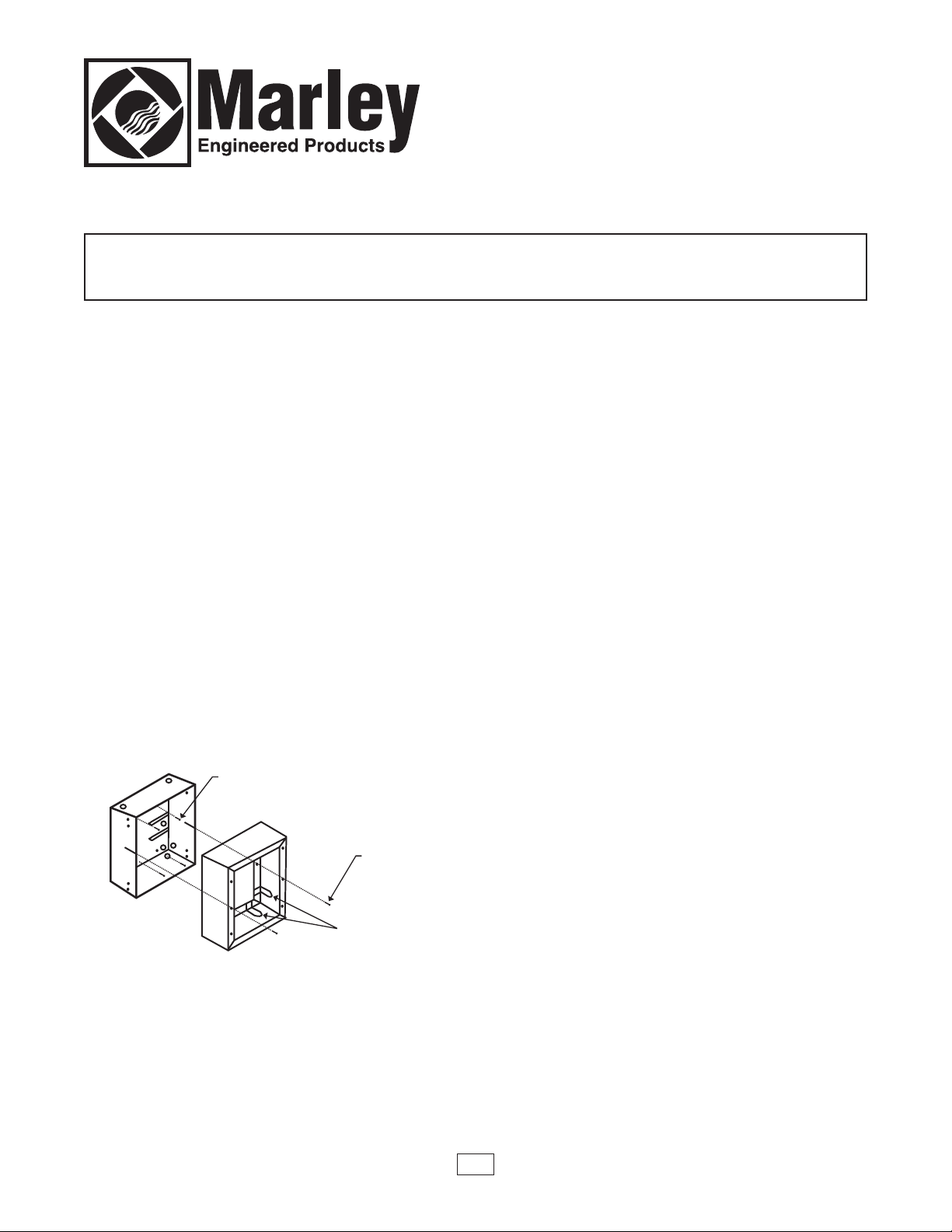
using (4) holes in back box. (See Figure 1).
3. If power supply is provided by a surface system
(such as conduit, surface raceways, etc.) remove
knockout in back box in side to match up with supply
location.Install appropriate cable connector to match
surface system and secure back box at least 8
inches (203 mm) of cable inside box.
Note: In order to match up with clearance knockouts in
surface frame, the knockouts located in corner next to
the knockout in back of box must be used.
(See Figure 1).
NAILS OR SCREWS
(4 REQ’D NOT SUPPLIED)
SCREWS
(2 REQ’D PROVIDED)
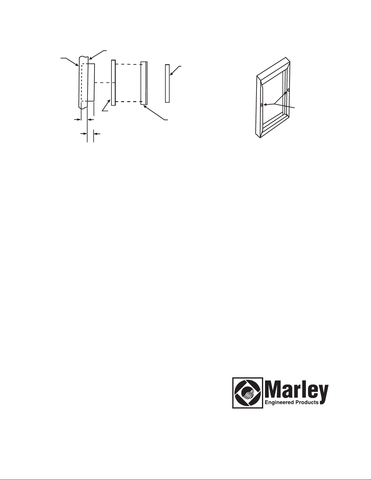
The A-S1 requires a minimum wall depth clearance of 23/4” (70 mm) and the A-S2 requires a minimum wall
depth clearance of 1-3/4” (44.5 mm). When using semirecessed sleeves the back box will need to be shimmed
to ensure that it is square with the wall.
INSTALLATION OF BACK BOX
Refer to “INSTALLATION OF BACK BOX IN NEW
CONSTRUCTION” or “INSTALLATION OF BACK BOX
IN EXISTING CONSTRUCTION” in heater instruction
sheet.
1. When using the A-S1 the front edge of the back box
must extend 1” (25.4 mm) beyond the finished wall
surface. When using the A-S2 the front edge of the
back box must extend 2” (51 mm) beyond the
finished wall surface (See Figure 2).
2. Shims must be used between the side of the back
box and the wall or ceiling stud to ensure the back
box installation is square with the finished wall.
INSTALLATION OF SEMI-RECESSED SLEEVE
1. Position the semi-recessed sleeve on the back box
and attach with two (2) #6 X 3/8” (3.5 mm X 9.5
mm) screws (provided) through holes as indicated in
Figure 2.
2. Finish the installation by referring to
“INSTALLATION AND WIRING OF HEATER/FAN
ASSEMBLY” in the heater instruction sheet.
Note: Mount the fan deck using the holes in the corner at
the thermostat and the corner opposite (diagonal) the
thermostat
.
GENERAL
SURFACE KIT
SUPPLY KNOCKOUTS
FIGURE 1
4. If supply is by surface system, remove the clearance
knockout in surface frame so frame will slide over
supply. (See Figure 1).
5. Slide surface frame over back box and proceed to
“INSTALLATION AND WIRING OF HEATER/FAN
ASSEMBLY” in heater instruction sheet.
1
Page 2
ALL
W
FIGURE 2
FINISH WALL SURFACE
A-S1 or
-S2
A
-3/4” (70mm) MIN. for A-S1
2
1-3/4” (44.5mm) MIN for A-S2
1” (25.4mm) for A-S1
2” (51mm) for A-S2
FRONT COVER
HEATER ASSEMBLY
SE THESE HOLES
U
TO MOUNT TO
BACK BOX
HOW TO ORDER REPAIR PARTS
In order to obtain any needed repair or replacement
parts, warranty service or technical information, please
contact Marley Engineered Products Service Center tollfree by calling 1-800-642-HEAT.
When ordering repair parts, always give the information listed as follows:
1. The Part Number
2. The Model Number
3. The Part Description
4. Date of Manufacture
ECR 35433
5200-2114-002 7/02
470 Beauty Spot Rd. East
Bennettsville, SC 29512 USA
Page 3
INSTRUCTIONS D’INSTALLATION
CADRE DE MONTAGE IN SURFACE A-SM ET
MANCHONS SEMI-ENCASTRÉS A-S1 ET A-S2
POUR L'USAGE AVEC RADIATEURS MURAUX À AIR PULSÉ. VOIR LES INSTRUCTIONS D’INSTALLA-
TION QUI ACCOMPAGNENT L’APPAREIL DE CHAUFFAGE POUR DES RENSEIGNEMENTS IMPORTANTS
RELATIFS À LA SÉCURITÉ ET AU MONTAGE DE L’APPAREIL.
Note: les manchons A-S1 ou A-S2 devraient être utilisés
pour un montage << semi-encastré >>. TOUT
CÂBLAGE DOIT ÊTRE CONFORME AU CODE DE
L’ELECTRICITÉ NATIONAL ET AUX RÈGLEMENTS
LOCAUX.
INSTALLATION DU BOÎTIER ARRIÈRE SUR
UN CADRE DE MONTAGE EN SURFACE
MODÈLE nº ASM
1. Amener le câble d’alimentation jusqu’à l’appareil de
chauffage en laissant une longueur libre d’au moins
8 po (203 mm) pour la connexion.
2. Si le câble d’alimentation est dans le mur, percer le
disque défoncable situé sur la paroi arrière du
boîtier et installer le collier de câble d’au moins 8 po
(203 mm) dans le boîtier. Utiliser les quatre (4) trous
du boîtier pour fixer le boîtier à la structure du
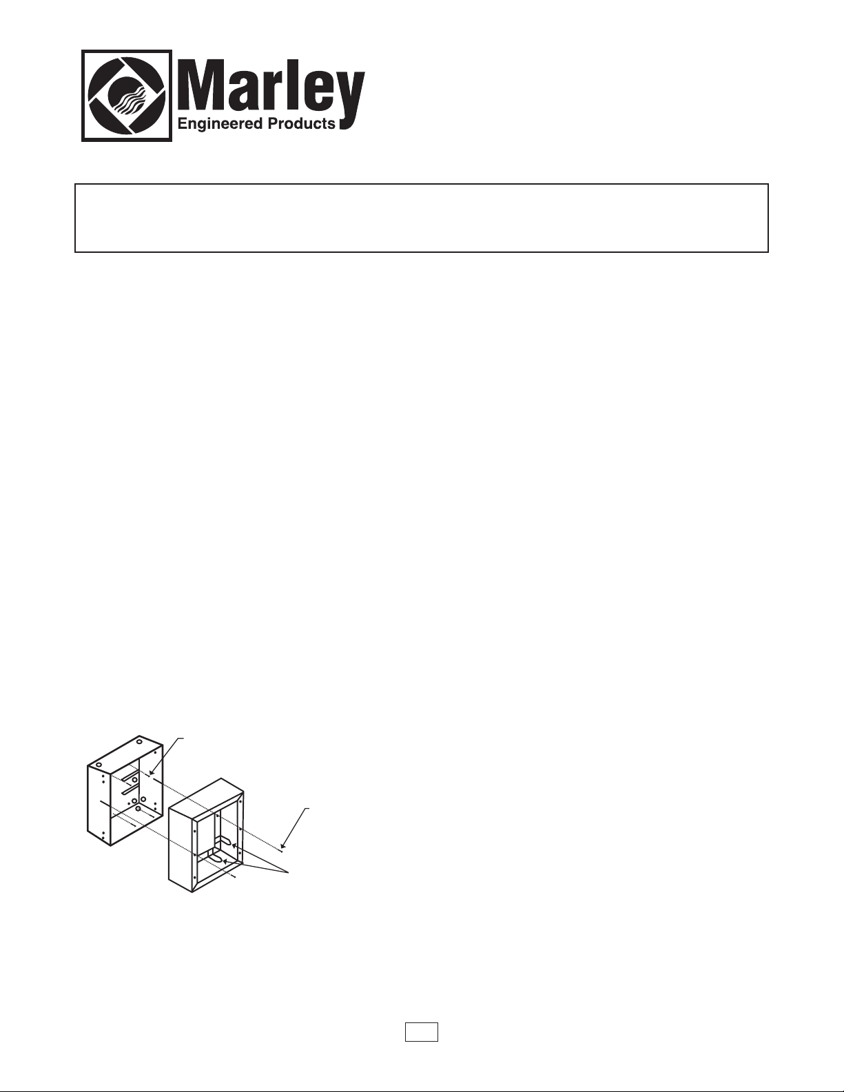
bâtiment. (Voir la Figure 1).
3. Si le câble d’alimentation est en surface (p.ex., dans
un conduit, dans des chemins de câbles en surface,
etc.) percer le disque défoncable du boîtier qui
correspond à l’emplacment du câble d’alimentation.
Installer un connecteur adéquat (système en
surface) et fixer le boîtier au mur par les quatre (4)
trous de la paroi arrière en laissant une longueur de
câble d’au moins 8 po (203 mm) dans le boîtier.
Note: Aux fins d’alignement avec les disques
défoncables du cadre de montage en surface, utiliser les
disques défoncables situés dans le coin adjacent au
disque de la paroi arrière du boîtier (Voir la Figure 1).
CLOUS OU VIS
(4 REQUIS, NON FOURNIES)
VIS
(2 REQUISES, FOURNIES)
DISQUES DÉFONCABLES
ALIMENTATION EN SUR-
FIGURE 1
4. Si l’appareil est alimenté par un système en surface,
percer le disque du trou de passage du cadre de
montage en surface de facon que le cadre glisse sur
l’alimentation (Voir la Figure 1).
5. Faire glisser le cadre de montage en surface sur le
boîtier arrière et procéder tel qu’indiqué à la section
INSTALLATION ET CÂBLAGE DE L’APPAREIL DE
CHAUFFAGE ET DU VENTILATEUR de la notice
d’instructions fournie avec l’appareil.
GÉNÉRALITÉS
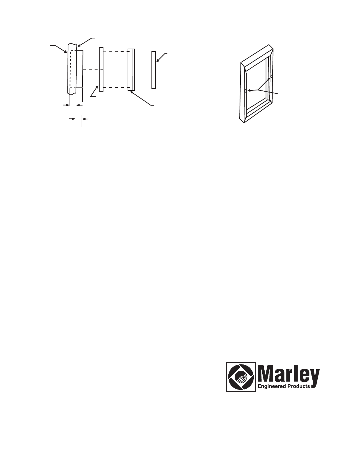
Le manchon A-S1 demande une profondeur murale minimale de 2-3/4 po (70 mm) et le A-S2 de 1-3/4 po (44.5
mm). Lorsque des manchons semi-encastrés sont utilisés, le boîtier arrière devra être calé pour s’assurer qu’il
est bien d’équerre avec le mur.
INSTALLATION DU BOÎTIER ARRIÈRE
Voir les sections INSTALLATION DU BOÎTIER
ARRIÈRE
DANS UNE NOUVELLE CONSTRUCTION ou
INSTALLATION DU BOÎTIER ARRIÈRE DANS UNE
CONSTRUCTION EXISTANTE dans la notice d’instructions qui accompagne l’appareil de chauffage.
1. Lorsque le manchon A-S1 est utilisé, le bord avant
du boîtier arrière doit être à 1 po (25.4 mm) au-delà
de la surface finie du mur. Lorsque le manchon A-
S2 est utilisé, le bord avant du boîtier arrière doit être a
2 po (51 mm) au-delà de la surface finie du mur
(Voir la Figure 2).
2. Utiliser des cales entre les côtés du boîtier et le
poteau du mur ou du plafond pour s’assurer que le
boîtier est d’équerre avec le mur fini.
INSTALLATION DE MANCHONS SEMI-ENCASTRÉS
1. Placer le manchon semi-encastrés sur le boîtier
arrière et le fixer au moyen de deux (2) vis nº 6 x
3/8 po (3.5 mm X 9.5 mm) (fournies) vissées dans
les trous, tel qu’indiqué à la Figure 2.
2. Voir la section INSTALLATION ET CÂBLAGE DE
L’APPAREIL DE CHAUFFAGE ET DU
VENTILATEUR dans la notice d’instructions qui
accompagne l’appareil de chauffage pour compléter
l’installation.
Note: Pour installer le bâti du ventilateur, utiliser les
trous
du coin près du thermostat et ceux du coin diagonalement opposé au thermostat
.
3
Page 4
UR
M
FIGURE 2
URFACE FINIE DU MUR
S
-S1 ou
A
A-S2
A-S1: 2-3/4 po (70mm) min.
A-S2: 1-3/4 po (44.5mm) min.
A-S1: 1 po (25.4mm)
A-S2: 2 po (51mm)
OUVERCLE AVANT
C
APPAREIL DE CHAUFFAGE
UTILISER CES TROUS
POUR INSTALLER LE
OÎTIER ARRIÈRE.
B
COMMENT COMMANDER DES PIÈCES
DE RECHANGE
Pour obtenir des pièces pour réparation ou remplacement, un
support sous garantie, ou des informations techniques, veuillez
contacter le centre de service de Marley Engineered Products au
numéro d'appel sans frais 1-800-642-HEAT.
En commandant des pièces de rechange, toujours fournir les
informations suivantes :
1. Numéro de pièce
2. Numéro de modèle
3. Description de pièce
4. Date de fabrication
ECR 35433
5200-2114-002 7/02
470 Beauty Spot Rd. East
Bennettsville, SC 29512 USA
 Loading...