

Page 1

Mechanical & Electrical Accessories
for 1800, 1900, 2500, 2600, C1800 & C2500
Installation Instructions
NOTE: Accessories described in this instruction manual are
intended for use with Marley Engineered Products 1800, 1900,
2500, 2600, C1800 and C2500 Series Model C baseboard
heaters only.
WARNING
!
This instruction sheet contains vital information for the proper
installation and use of the accessories described herein.
Carefully read this manual before installation, operation, or service of the accessory. Failure to follow these instructions could
result in fire, electric shock, death, serious personal injury, or
property damage. Save these instructions for reference by future
users.
WARNING: HAZARD OF FIRE OR ELECTRIC SHOCK.
1. Be sure electric power is disconnected at main fuse or circuit
breaker distribution panel before installation or servicing.
2. The installation must comply with all Local and National
Electrical Codes and utility requirements.
3. Refer to installation instructions provided with the heater
when installing these accessories.
4. Check accessory and heater nameplate to verify power
requirements match power supply coming to heater and
accessory. Make sure total power requirements do not
exceed ratings of accessory.
5. When using RSA transformer relay accessory, supply wires
must be minimum 90° C.
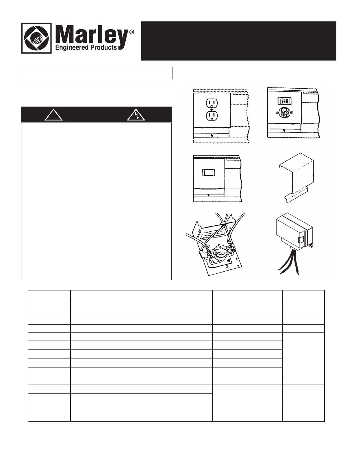
Series Baseboard Heaters
RA1
FS
DSW2
PR
HCA
RSA
MODEL NO.
HCA121520 **
HCA241520 **
DSW2 *
RA1 **
RSA1224C
RSA2024C
RSA2424C
RSA2724C
RSA3724C
RSA6024C
PR24C
PR120C
FS *
FSJ2 *
* Followed by WCA or NWCA suffix
** Followed by WC or NWC suffix
Suffix should match heater suffix
ECR 40406 / 40495 3/15 5200-2206-007
Heat/Cool Switch w/Receptacle
Heat/Cool Switch w/ Receptacle
Power ON/OFF Switch DPST
Duplex Receptacle
Low Voltage Relay w/Transformer 120/24V
Low Voltage Relay w/Transformer 208/24V
Low Voltage Relay w/Transformer 240/24V
Low Voltage Relay w/Transformer 277/24V
Low Voltage Relay w/Transformer
Low Voltage Relay w/Transformer
Power Relay SPST 24V Coil
Power Relay SPST 120V
Filler Section
Joiner Section
DESCRIPTION
20 Amps @ 120 VAC
20 Amps @ 250 VAC
20 Amps @ 120 - 177 VAC
15 Amps @ 120 VAC
25 Amps @ 120 VAC
25 Amps @ 208 VAC
25 Amps @ 240 VAC
22 Amps @ 277 VAC
17 Amps @ 347 VAC
12 Amps @ 600 VAC
30 Amps @ 120 - 240 VAC
23 Amps @ 277 VAC
10 Amps @ 347 & 600 VAC
RATINGS
WIRING DIAGRAM
Figure 1
Figure 2
Figure 3
Figure 4
Figure 5
Page 2
ELEMENT
B
ASEBOARD
H
EATER
W
ALL THERMOSTAT
(OPTIONAL)
B
LACK
S
WITCH
B
LUE
W
HITE
WHITE WITH
BLACK TAP E
GROUND
R
ECEPTACLE
AC ACCESSORY
L
1
L2
HIGH LIMIT
L1
L2
HIGH LIMIT
E
LEMENT
SWITCH
HIGH LIMIT
E
LEMENT
BASEBOARD HEATER
LVR ACCESSORY
G
ROUND
TRANSFORMER RELAY
TO 24 VOLT
THERMOSTAT
R
ED
WHITE
L1
L
2
BLACK
YELLOW
BLUE
LVR ACCESSORY
GROUND
BASEBOARD HEATER
ELEMENT
HIGH LIMIT
BLUE
YELLOW
BLACK
TRANSFORMER RELAY
TO 24 VOLT
THERMOSTAT
RED
WHITE
L1
L
2
H
IGH LIMIT
H
IGH LIMIT
BASEBOARD HEATER
B
ASEBOARD HEATER
ELEMENT
ELEMENT
TRANSFORMER RELAY
TO 24 VOLT
T
HERMOSTAT
LV R
BLUE
YELLOW
BLACK
L
1
L2
RED
W
HITE
HIGH LIMIT
ELEMENT
L1
L2
GROUND
POWER RELAY
TO EXTERNAL CONTROL
VOLTAGE SOURCE
HIGH LIMIT
ELEMENT
TO EXTERNAL CONTROL
VOLTAGE SOURCE
GROUND
L1
L2
POWER RELAY
POWER RELAY
TO EXTERNAL CONTROL
VOLTAGE SOURCE
ELEMENT
ELEMENT
GROUND
L1
L2
HIGH LIMIT
HIGH LIMIT
L1
D
BLACK
WHITE
GROUND
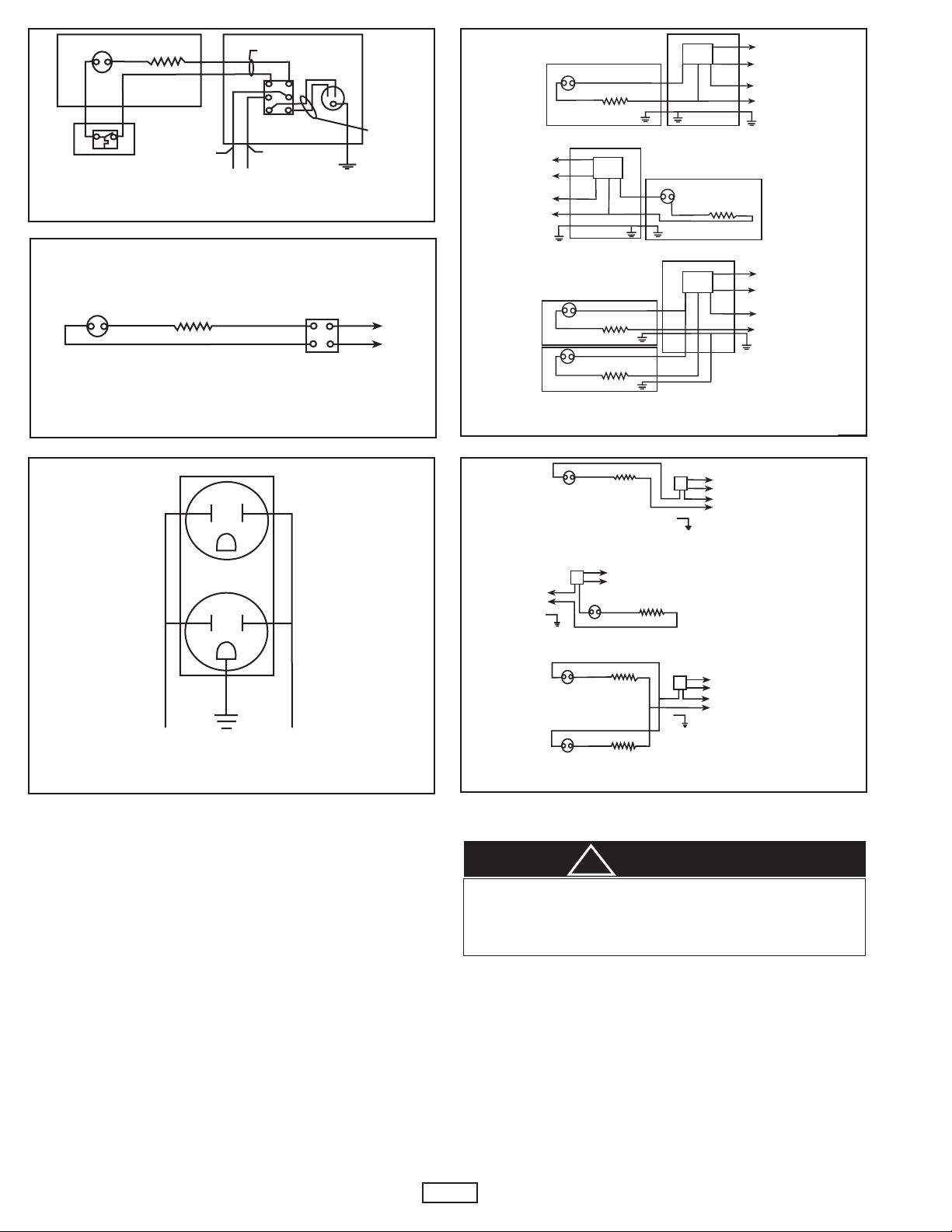
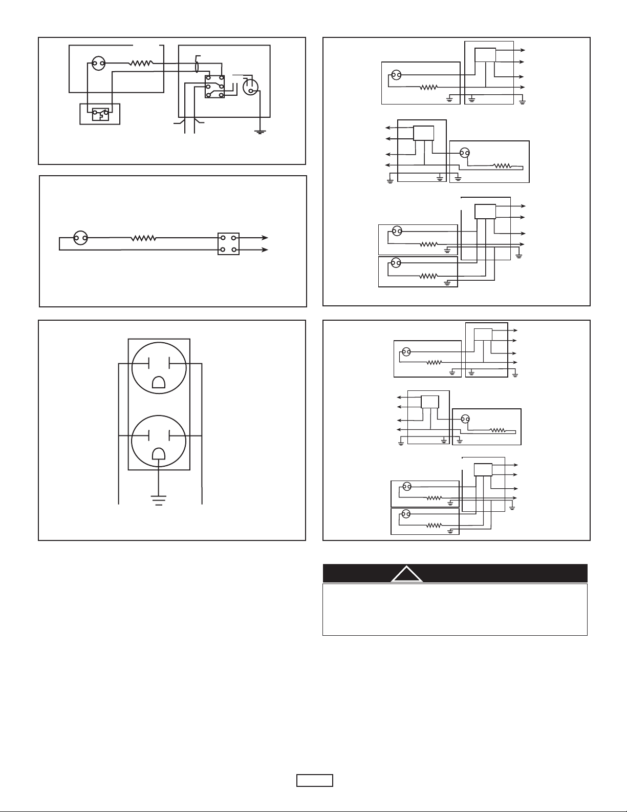
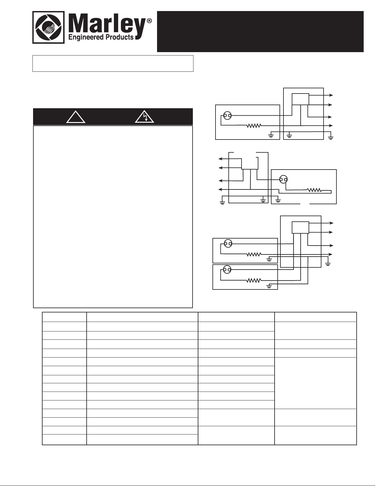
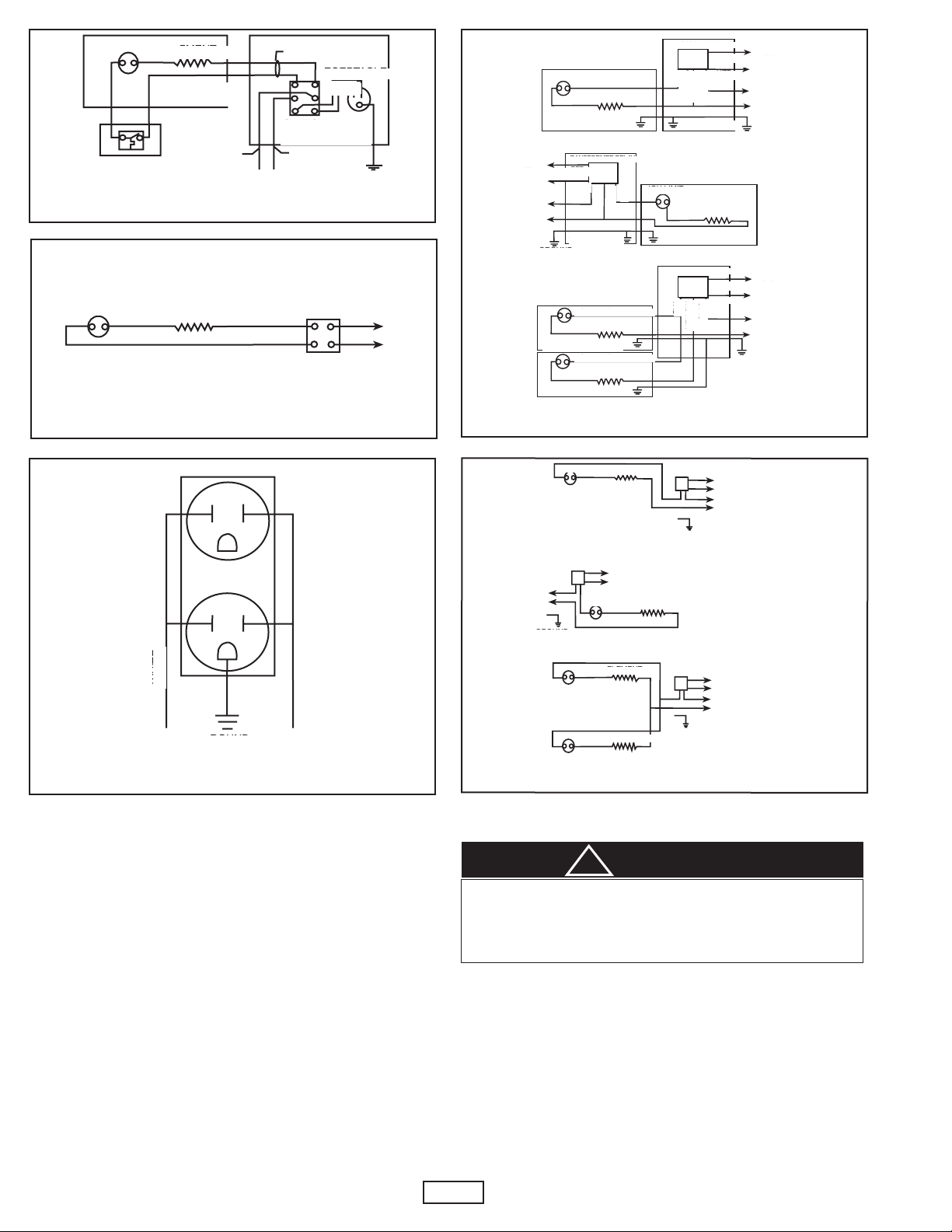
Figure 1. HCA Heat/Cool Switch w/Receptacle
Figure 2. DSW2 Power ON/OFF Switch Figure 4. RSA Transformer Relay
5A
5B
5C
Figure 3. RA1 120 Volt Duplex Receptacle Figure 5. PR Power Relay
HCA121520 and HCA242520
Do not use Heat-Cool Transfer Switch as an “OFF/ON” switch.
Operation of baseboard should be regulated by a wall mounted
thermostat. Operation of air conditioner should be regulated by
the thermostat provided in the air conditioner.
1. Plug air conditioner into receptacle. Set heat-cool transfer switch
to “OFF” position. Turn heating thermostat to highest position.
If heater or air conditioners are energized, turn off power
supply and have wiring rechecked.
2. Set heat-cool transfer switch to “HEAT” position. If baseboard
heater does not operate, turn off power supply and have wiring
rechecked.
3. Set heat-cool transfer switch to “COOL” position. If air conditioner does not operate, turn off power supply and have wiring
rechecked.
2
1. All electrical work must conform to Local and National Electrical
Codes. This unit must be connected with a 20 amp. maximum
branch circuit. The minimum wire size allowable is No.
12AWG Copper. NOTE: The use of UL Listed connectors of
the proper size is required.
2. The transfer switch must be installed in the wiring compart-
3. Connect center switch leads (black for switches rated 240V,
4. Fold wires carefully and install transfer switch in place of wiring
5. Reconnect power at main fuse or circuit breaker distribution
ment where the power wiring has been brought in. Remove
that wiring compartment cover and discard.
one white and one black for switches rated 120V), to the power
supply wires and connect the blue leads through the thermostat
to the heater wire as shown in the wiring diagram, (Figure 1).
compartment cover.
panel.
OPERATION
CAUTION
!
Page 3
DSW2
1. All electrical work must conform to Local and National Electrical
Codes. The minimum wire size allowable is No. 12AWG Copper.
NOTE: The use of UL Listed connectors of the proper size
is required.
2. The Power ON/OFF switch is intended to be installed in the
wiring compartment where the power wiring has been brought
in. Remove wiring compartment cover and discard.
3. Connect the Power ON/OFF switch leads to the heater and
power leads as shown in the wiring diagram, (Figure 2).
4. Fold wires carefully and install Power ON/OFF in place of
wiring compartment cover.
5. Reconnect power at main fuse or circuit breaker distribution
panel.
7. For left end connection, remove wire nut connecting crossover
wire and limit control wires together. Connect power supply
wire (L2), the larger yellow wire, and crossover wire together.
The blue wire is to be connected to the high limit wire.
Connect power supply wire (L1) to larger black wire.
8. After all electrical power connections are completed, install the
thermostat as described in the Thermostat Owners Manual.
Connect wires from the thermostat to the red and white
wires (refer to paragraph 5) with suitable UL Listed wire
nuts. If more heaters are to be connected to the same
thermostat, refer to wiring diagram in Figure 5.
9. Once wiring is complete, peel off the back of the conductor
label included in this kit and attach it to the back of the control
box cover. Reinstall cover.
RA1
1. All electrical work must conform to Local and National Electrical
Codes. This unit must be connected to a separate 15 amp
maximum branch circuit. The minimum wire size allowable is
No. 14AWG Copper.
NOTE: The use of UL Listed connectors of the proper size
is required.
2. The duplex receptacle may be installed in either the left or right
wiring compartment. Remove the desired wiring compartment
cover and discard.
3. Drill hole through floor or wall at knockout location where
branch circuit supply will enter the wiring compartment. (This
may require removing the heater).
4. Feed branch circuit supply wire through drilled hole and knockout in heater. Install cable connector (not supplied).
5. Connect branch circuit supply to duplex receptacle as shown
in wiring diagram, (Figure 3).
6. Reconnect power at main fuse or circuit breaker distribution
panel for the heater and duplex receptacle.
RSA1224C, RSA2024C, RSA2424C,
RSA2724C, RSA3424C and RSA6024C
INSTALLATION
1. All electrical work must conform to Local and National Electrical
Codes. The use of UL Listed connectors of the proper size
is required. Supply wiring must be suitable for 90° C.
2. Remove the control box cover where the power supply leads
are. Remove small knockout in back of baseboard and make
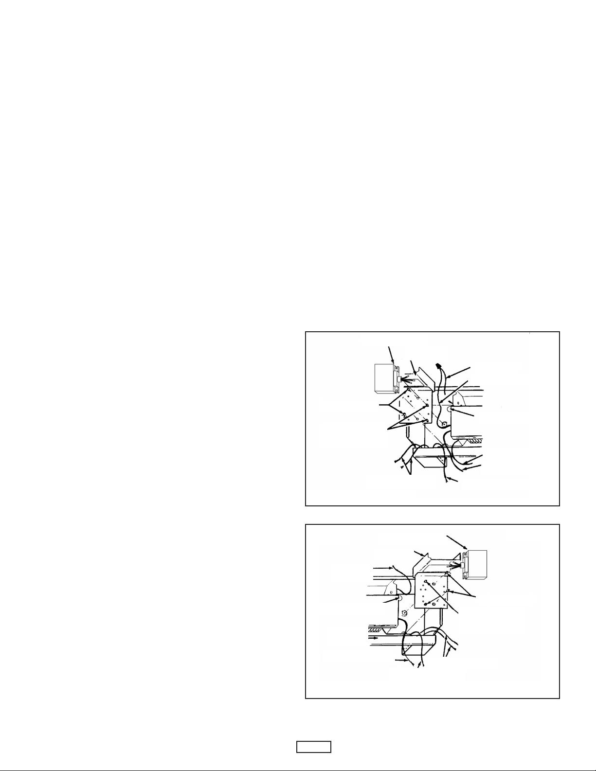
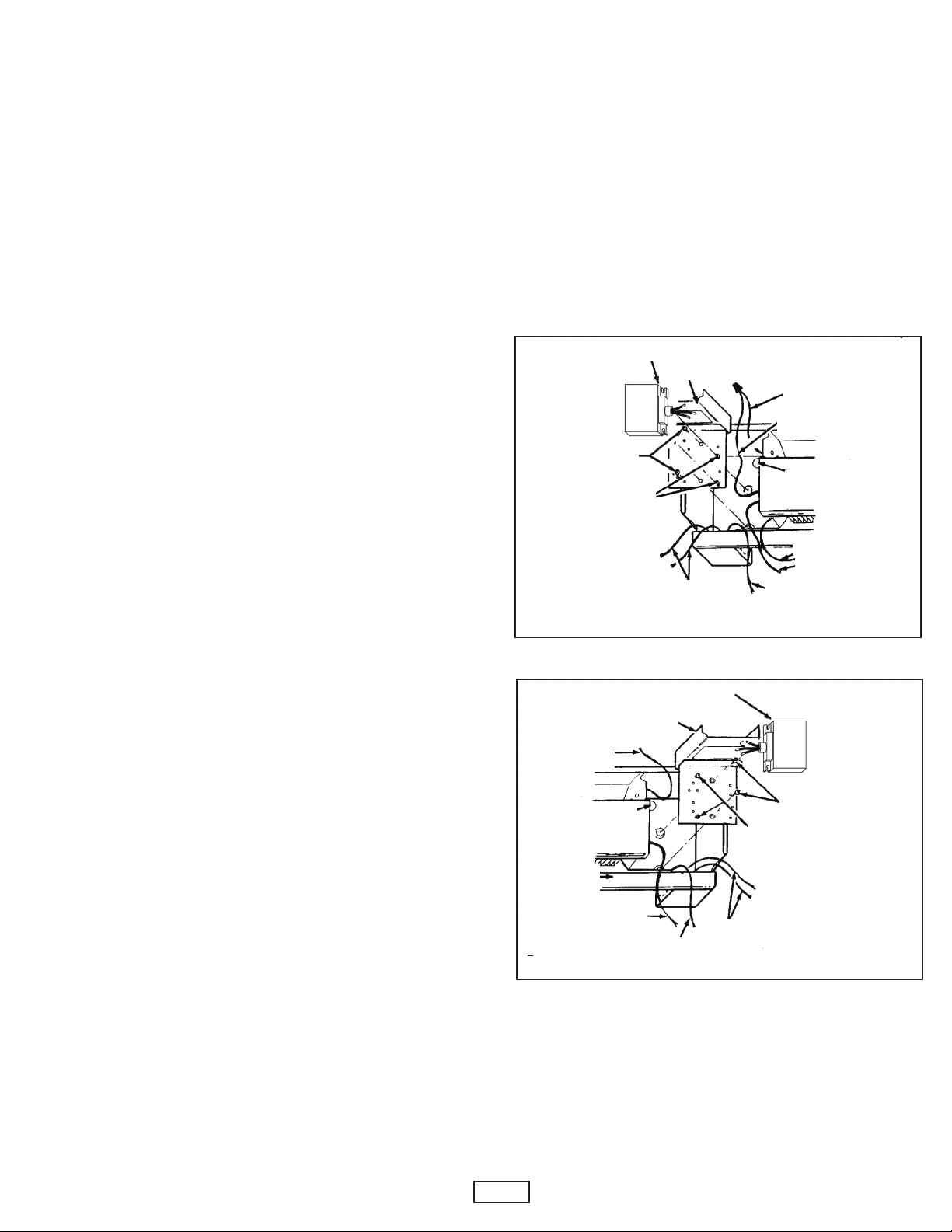
aligning hole in wall (See Figures 6 and 7). Fish thermostat
wires through this hole.
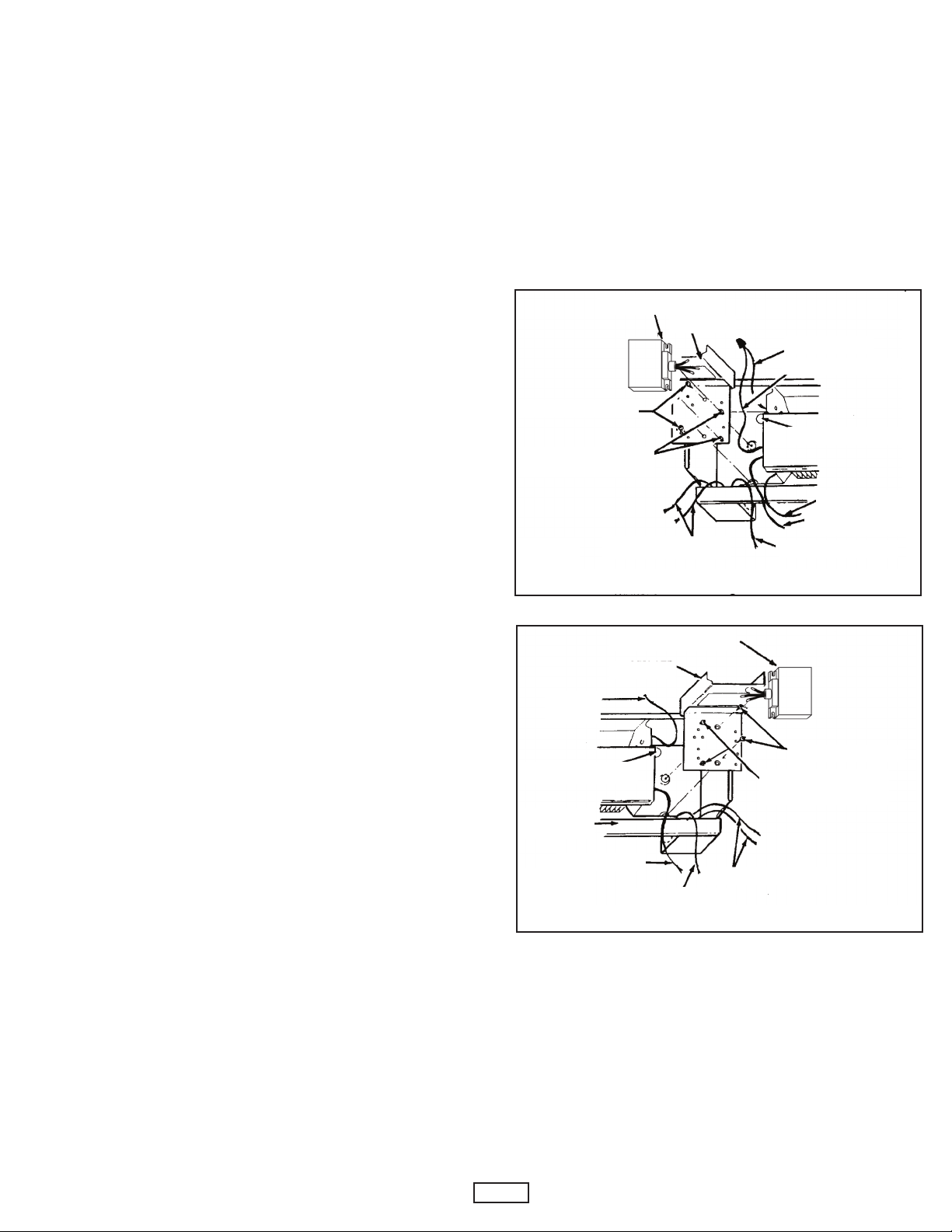
3. Loosely install both transfer relay screws. Attach baseplate as
shown in Figures 6 or 7.
4. Slide transformer/relay under loosely installed screws in base
plate and tighten screws. NOTE: For left end installation
transformer/relay is mounted upside down.
5. Push the red and white transformer wires through the hole in
the top of the baseplate. Make 24V thermostat connections in
the compartment formed by the baseplate and the top of the
wiring compartment. (See wiring diagram Figure 4).
6. For right end connection remove wire nut and connect power
supply wire (L2) to the larger yellow wire and to the element
lead wire. Connect power supply wire (L1) to larger black wire
and connect blue wire to return wire. (See wiring diagram
Figure 4).
TRANSFORMER RELAY
BASEPLATE SCREWS
TRANSFORMER/RELAY
CREWS
S
POWER SUPPLY WIRES
Figure 6. Left End
TRANSFORMER RELAY
BASEPLATE
RETURN
WIRE
SMALL KNOCKOUT
BASEBOARD
HEATER
ELEMENT WIRE
GROUND WIRE
Figure 7. Right End
ASEPLATE
B
POWER SUPPLY WIRES
RETURN WIRE
LIMIT CONTROL WIRE
SMALL KNOCKOUT
ELEMENT WIRE
LIMIT CONTROL
IRE
W
GROUND WIRE
BASEPLATE SCREWS
TRANSFORMER/RELAY
SCREWS
3
Page 4
CHECK OPERATION
1. Before connecting power supply, be sure all thermostats are
turned to “LOW” or “NO HEAT”.
2. Connect power supply at distribution box. Wait 3 to 5 minutes
and check to see that none of the heaters are operating.
Should any of the heaters be operating, disconnect power supply and check wiring.
3. If none are operating, turn the thermostats to the highest position and wait 3 to 5 minutes. Check to see that all heaters are
operating. If any are not operating, disconnect power supply
and check wiring.
PR24C and PR120C
1. All electrical work must conform to Local and National Electrical
Codes. The use of UL Listed connectors of proper size is
required.
2. On PR24 model, using 24 volt class 2 control circuit wiring,
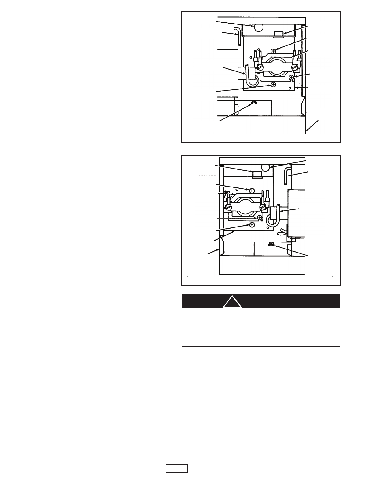
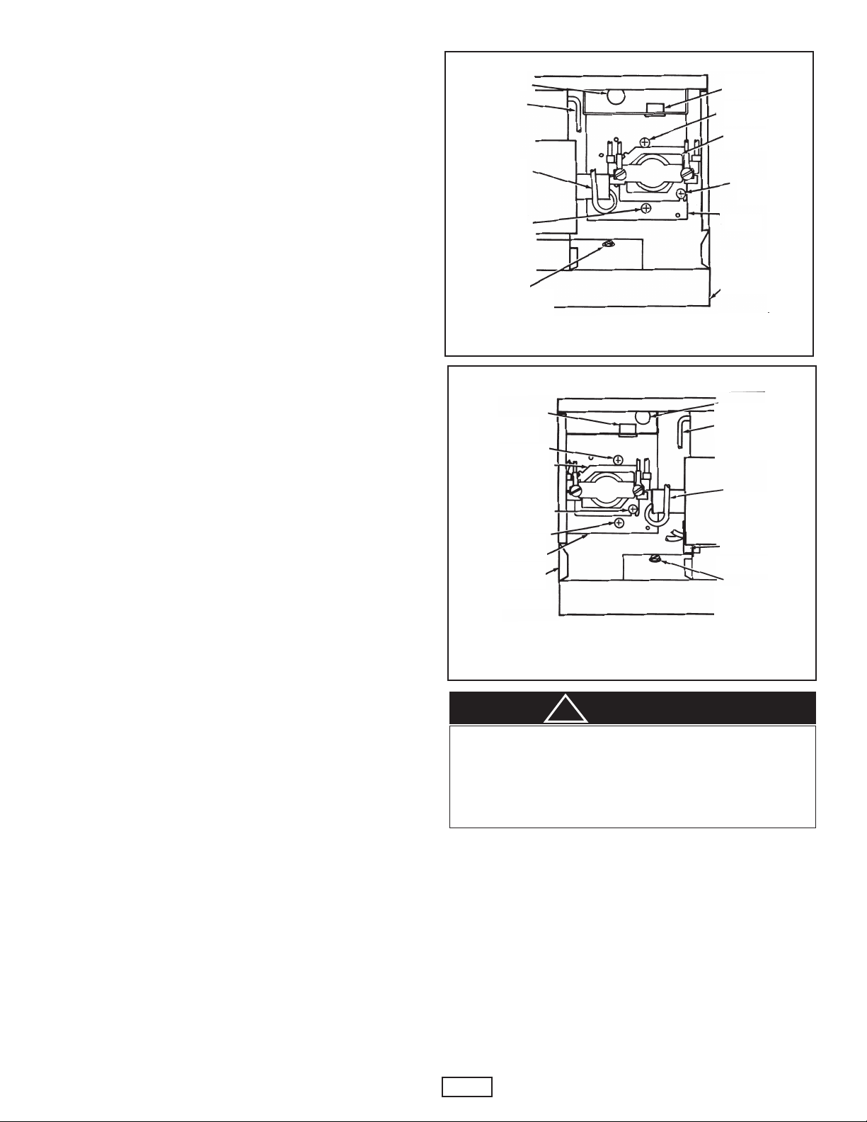
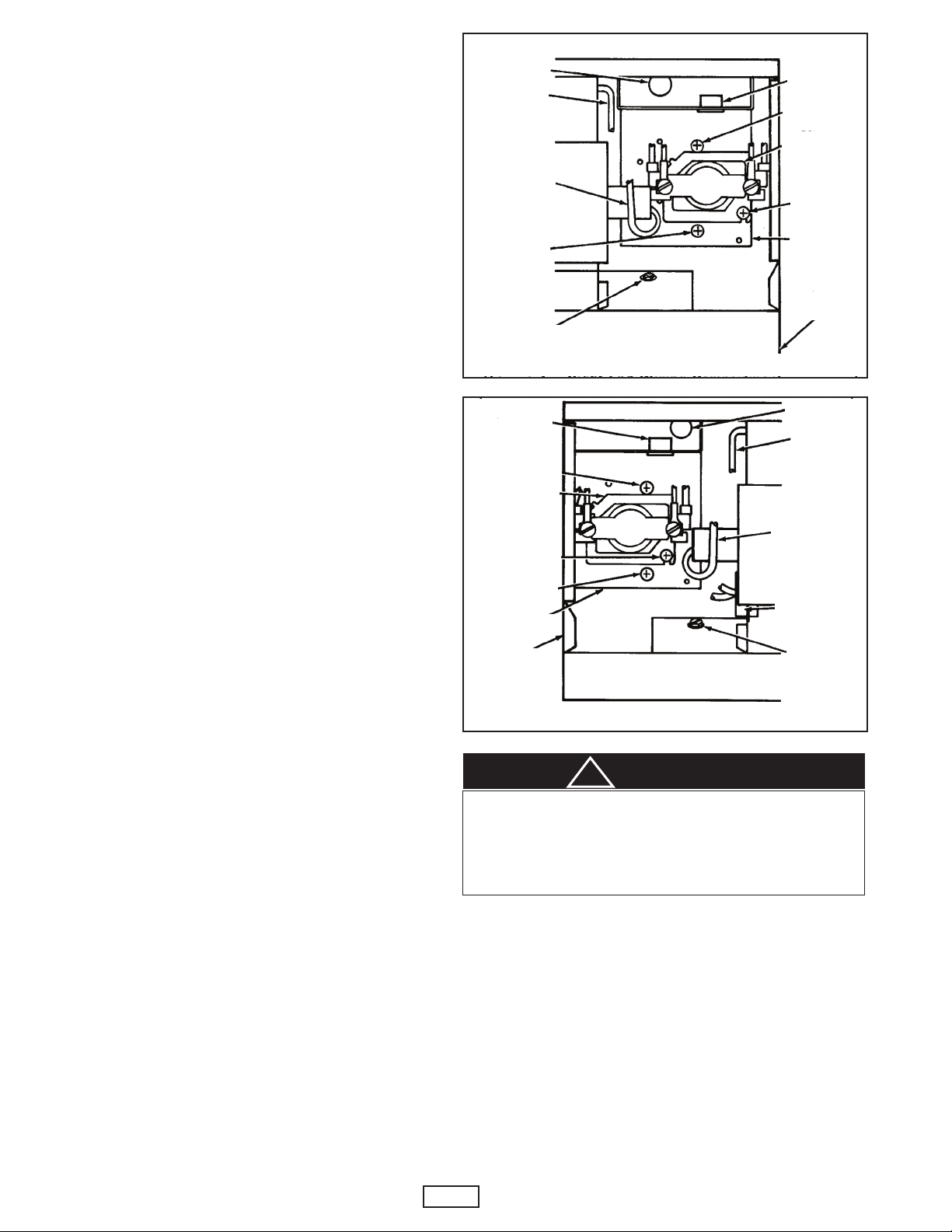
remove small knockout in back of baseboard and make aligning hole in wall (See Figures 8 or 9). Route 24 volt class 2
external control circuit wires through this hole. On PR120
model, the control circuit wiring connections may be made in
the heater wiring compartment.
3. Attach baseplate to back of wiring compartment with screws
provided. (See Figure 8 or 9). Insert snap bushing in appropriate hole in baseplate top.
4. Mount power relay on baseplate and securely fasten with screw
provided. See Figure 8 or 9 for proper mounting location on
baseplate.
5. On PR24 model, using 24 volt class 2 control circuit wiring,
push the two red relay wires up through the hole in the top of
the baseplate. Make all external 24 volt class 2 control circuit
wiring connections in the compartment formed by the
baseplate and the top of the wiring compartment. On the
PR120 model, connect external 120 volt control circuit
wiring in the heater wiring compartment by connecting to
the red control wire. The compartment formed by the base
plate and top of the heater wiring compartment is not used on
the PR120 Model.
6. For right end connection, remove wire nut and connect return
wire to one black lead on power relay. Connect power supply wire (L1) to other black lead on power relay. Connect
power supply wire (L2 or N) to element lead wire. (See wiring
diagram, Figure 5A).
7. For left end connection, remove wire nut connecting the limit
control and connect limit control wire to one black lead on
power relay. Connect power supply wire (L1) to other black
lead on power relay. Connect power supply (L2 or N) to
crossover wire. (See wiring diagram, Figure 5B).
8. If more heaters are to be connected to same power relay, refer
to wiring diagram Figure 5C. Do not exceed ampacity rating of
power relay.
FSJ2 and FS
The FS Filler Sections provide for a uniform appearance by covering open space between heaters or between the end of a heater
and the wall. If heaters are butted together, Marley Model Number
FSJ2 Joiner Strip should be used.
These instructions are provided to assist you in the installation
and prevent unnecessary problems that you may encounter.
Read and study these instructions as well as the instructions provided with the heaters before installing.
SMALL
NOCKOUT
K
RETURN
WIRE
LEMENT
E
WIRE
ASEPLATE
B
SCREW
GROUND
SCREW
GROMMET
BASEPLATE
SCREW
OWER
P
ELAY
R
RELAY
SCREW
ASEPLATE
B
BASEBOARD
EATER
H
Figure 8. Right End Wiring Compartment
USHING
B
BASEPLATE
CREW
S
POWER RELAY
RELAY SCREW
BASEPLATE
SCREW
BASEPLATE
BASEBOARD
HEATER
SMALL
KNOCKOUT
ETURN
R
WIRE
ELEMENT
WIRE
THERMAL
CUT OUT
GROUND
SCREW
Figure 9. Left End Wiring Compartment
CAUTION
!
To prevent possible damage to internal wiring, prior to installing
the filler section, remove the heater junction box cover(s) at the
end of the heater(s) where the filler is to be installed. Position
all wiring in the junction boxes so it is not in the area where the
self-tapping screw (Step 4) will be installed.
1. Mount the heaters on the wall in accordance with the heater
installation instructions. Make sure the heaters are at the
same mounting height from the floor to assure a level mounting of the filler section.
2. Position the filler section on top of the heater(s) and press
down toward the bottom of the filler to assure a tight fit. The
section will snap into place. Do not mount over the junction
box screw.
3. If the filler section is to be mounted between a heater and a
wall, a block of wood to support one end of the filler should be
attached to the wall, level with the top of the heater.
4. Attach filler sections with sheet metal screw, supplied by others,
in the bottom of the filler and into the baseboard.
4
Page 5
LIMITED WARRANTY
All products covered by this instruction sheet are warranted against defects in workmanship and materials for one year from date of
installation. This warranty does not apply to damage from accident, misuse, or alteration; nor where the connected voltage is more than
5% above the nameplate voltage; nor to equipment improperly installed or wired or maintained in violation of this instruction sheet. All
claims for warranty work must be accompanied by proof of the date of installation.
The customer shall be responsible for all costs incurred in the removal or reinstallation of products, including labor costs, and shipping
costs incurred to return products to a Marley Engineered Products Service Center, and we will repair or replace, at our option, at no
charge to you with return freight paid by Marley. It is agreed that such repair or replacement is the exclusive remedy available from Marley
Engineered Products.
THE ABOVE WARRANTIES ARE IN LIEU OF ALL OTHER WARRANTIES EXPRESSED OR IMPLIED, AND ALL IMPLIED WARRANTIES OF MERCHANTABILITY AND FITNESS FOR A PARTICULAR PURPOSE WHICH EXCEED THE AFORESAID EXPRESSED
WARRANTIES ARE HEREBY DISCLAIMED AND EXCLUDED FROM THIS AGREEMENT. MARLEY ENGINEERED PRODUCTS
SHALL NOT BE LIABLE FOR CONSEQUENTIAL DAMAGES ARISING WITH RESPECT TO THE PRODUCT, WHETHER BASED
UPON NEGLIGENCE, TORT, STRICT LIABILITY, OR CONTRACT.
Some states do not allow the exclusion on limitation of incidental or consequential damages, so the above exclusion or limitation may
not apply to you. This warranty gives you specific legal rights, and you may also have other rights which vary from state.
For the address of your nearest authorized service center, contact Marley Engineered Products, 470 Beauty Spot Road East,
Bennettsville, SC 29512 USA. Merchandise returned to the factory must be accompanied by a return authorization and service identification tag, both available from the above location. When requesting return authorization, include all catalog numbers shown on the
products.
HOW TO OBTAIN WARRANTY SERVICE AND
WARRANTY PARTS PLUS GENERAL INFORMATION
1. Warranty Service or Parts 1-800-642-4328
2. Purchase Replacement Parts 1-800-654-3545
3. General Product Information www.marleymep.com
Note: When obtaining service always have the following:
1. Model number of the product
2. Date of manufacture
3. Part number or description
470 Beauty Spot Rd. East
Bennettsville, SC 29512 USA
5
Page 6
Accessoires pour Radiateurs
Électriques séries 1800, 1900, 2500, 2600,
Instructions d´Installation
AVERTISSEMENT
!
Ce feuillet d´instructions contient des renseignements essentiels
à l´installation et à l´exploitation correctes des accessoires
décrits ci-après. Lisez attentivement la notice avant d´installer,
de faire fonctionner ou de réparer l´accessoire. Toute derogation
à ces instructions peut entrainer un incendie, unchoc électrique,
des blessures graves ou mortelles et des dommages materiels.
Conservez ces instructions pour renseigner les futurs utilisateurs.
AVERTISSEMENT: RISQUE D´INCENDIE OU
DE CHOC ÉLECTRIQUE
1. Coupez toute source d´alimentationdu radiateur au panneau
de dérivation avant d´entreprendre l´installation ou la
maintenance
2. L´installation doit être conforme aux exignces pertinentes
des codes locaux, du Code de l´électricité et des normes du
fournisseur d´électridité.
3. Lors de l´installation de ces accessoires, consultez les
instructions d´installation fournes avec le radiateur.
4. Vérifiez la plaque signalétique de l´accessoire et du radiateur et assurez-vous que la tension nominal correspound à
la tension du réseau. Assurez-vous que la puissance totale
commutee ne dépasse pas les caractéristiques nominales
de l´accessoire.
5. Si vous installez l´accessoire relais-transformateur RSA,
utilisez des câbles d´alimentation 90° C.
C1800 et C2500
RA1
DSW2
PR
HCA
FS
RSA
MODÈLE
HCA121520 **
HCA241520 **
DSW2 *
RA1 **
RSA1224C
RSA2024C
RSA2424C
RSA2724C
RSA3724C
RSA6024C
PR24C
PR120C
FS *
FSJ2 *
* Suivi par les suffixes “WCA” ou “NWCA”.
** Suivi par les suffixes WC ou NWC
Le suffixe doit être le même que celui de l’appareil de chaffage.
ECR 40406 / 40495 3/15 5200-2206-007
Commutateur chauffage-climatiotion avec prise de courant
Commutateur chauffage-climatiotion avec prise de courant
Puissance ON/OFF
Prise de courant double
Relais basse tension avec transformateur 120/24V
Relais basse tension avec transformateur 208/24V
Relais basse tension avec transformateur 240/24V
Relais basse tension avec transformateur 277/24V
Relais basse tension avec transformateur
Relais basse tension avec transformateur
Relais unipolaire, bobine, 24V
Relais unipolaire, bobine, 120V
Fiausse Section
Raccord
DESCRIPTION
CARACTÉRISTIQUES
20 A à 120 V c.a.
20 A à 250 V c.a.
20 A à 120 - 177 V c.a.
15 A à 120 V c.a.
25 A à 120 V c.a.
25 A à 208 V c.a.
25 A à 240 V c.a.
22 A à 277 V c.a.
17 A à 347 V c.a.
12 A à 600 V c.a.
30 A à 120 - 240 V c.a.
23 A à 277 V c.a.
10 A à 347 & 600 V c.a.
SCHÉMA
Figure 1
Figure 2
Figure 3
Figure 4
Figure 5
Page 7
Unite de
C
hauffe
R
adiateur
T
hermostat mural
(racultatif)
Noir
I
nterrupteur
Bleu
Blanc avec
r
uban noir
T
erre
P
rise
A
ccessoire climatiseur
L
1
L2
T
hermostat limiteur
Blanc
L1
L2
Thermostat limiteur
Unite de
Chauffe
Interrupteur
A
ccessoire LVR
Terre
Transformateur Relais
Thermostat
24 V
R
ouge
B
lanc
L1
L2
Noir
Jaune
Bleu
L
1
L2
LV R
L
1
L2
U
nite de
Chauffe
R
adiateur
T
hermostat limiteur
Thermostat limiteur
T
ransformateur Relais
T
hermostat
24 V
Rouge
B
lanc
Noir
Jaune
Bleu
Accessoire LVR
Radiateur
Unite de
Chauffe
Terre
Thermostat limiteur
Unite de
Chauffe
Radiateur
T
hermostat limiteur
Unite de
C
hauffe
Radiateur
Transformateur Relais
R
ouge
Blanc
T
hermostat
24 V
Bleu
Jaune
Noir
Accessoire LVR
Terre
T
ransformateur Relais
T
hermostat
24 V
R
ouge
B
lanc
L
1
L
2
Noir
Jaune
Bleu
L1
L
2
LV R
L1
L2
Unite de
Chauffe
Radiateur
Thermostat limiteur
Thermostat limiteur
Transformateur Relais
T
hermostat
24 V
Rouge
B
lanc
Noir
Jaune
Bleu
Accessoire LVR
Radiateur
Unite de
Chauffe
Terre
Thermostat limiteur
Unite de
Chauffe
Radiateur
Thermostat limiteur
Unite de
Chauffe
Radiateur
T
ransformateur Relais
R
ouge
B
lanc
Thermostat
24 V
Bleu
Jaune
Noir
Terre
B
lan
c
Noir
L1
D
IG. 4A BRANCHMENT COTE DROIT
F
FIG. 4B BRANCHMENT COTE GAUCHE
Figure 1. Commutateur chauffage-climatisation avec prise HCA
IG. 4C BRANCHMENT EN BATTERIE
F
1. L´installation électrique doit être conforme aux codes locaus et
2. Le commutateur doit être installe dans la boite de connexions
3. Connectez les fils de raccordement centraux (noirs sur les
4. Repoussez les câbles delecatement et posez le commutateur
5. Rétablissez l´alimentation au panneau de fusibles ou de
Figure 2. Puissance ON/OFF DSW2
Figure 4. Transformateur-relais LVR
FIG. 5A BRANCHMENT COTE DROIT
Figure 3. Prise double 120 v RA1 Figure 5. Relais
HCA121520 et HCA242520
au Code de l´électriqué. Branchez cet appareil à une dérivad´au plus 20 A. Utilisez des câbles en cuirve d´une section d´au moins 12 AWG. NOTE: lew connecteurs doivent
être approuvés et grosseur appropriée.
où se trouvent les conducteurs d´alimentation. Enlevez le
couvercle de cette boite et mettez-le au rebut.
interupteurs de 240 V, un blanc et un noir sur les interrupteurs
120 V) aux conducteurs d´alimentation et les fils bleus au thermostat et au radiateur, selon le schéma (Figure 1).
à la place du couvercle de la boîte.
disjoncteurs.
N´utilisez pas le commutateur chauffage-climatisation comme
un interrupteur général. Le radiateur devrait être commandé.
Par un thermostat mural et le climatiseur par le thermostat intégré à ce dernier.
1. Branchez le climatiseur dans la prise. Placez le commutateur
chauffage-climatisation à la position Arrêt. Réglez le thermostat de chauffage à la température maximale et le thermostat
de climatisation a la temperature minimale. Si le radiateur ou
le climatiseur fonctionne, coupez l´alimentation et faites vérifier
les connexions.
2. Réglez le commutateur chauffage-climatisation à la position
Chauffage. Si le radiateur de fonctionne pas, coupez l´alimentationet faites vérifier les connexions.
7
FIG. 5C
ATTENTION
!
EXPLOITATION
FIG. 5B BRANCHMENT COTE GAUCHE
Page 8
3. Réglez le commutatuer chauffage-climatisation à la position
Climatisation. Si le climatiseur de fontionne pas, coupez l´alimentation et faites vérifier les connexions.
DSW2
1. L´installation électrique doit être conforme aux codes locaux et
au Code de l´électricité. Utilisez des câbles en cuivre d´une
section d´moins 12 AWG. NOTE. Les connecteurs doivent
etre approuvés et de grosseur appropriée.
2. Puissance ON/OFF doit être installé dans la boîte de connexion où de trouvent les conducteurs d´alimentation. Enlevez le
couver-cle de cette boîte et mettez-le au rebut.
3. Connectez les fils de raccordement de l´interupteur aux con
ducteurs d´alimentation et au radiateur, selon le schéma (Figure 2)
4. Repoussez les cables delicatement et posez le commutateur
à la place du couvercle de la boîte.
5. Rétalbissez l´alimentation au panneau de fusibles ou de disjoncteurs.
RA1
1. L´installation électrique doit être conforme aux codes locaux et
au Code de l´électricaté. Branchez cet appareil a une dérivation d´au plus 15 A. Utilisez des câbles en Cuivre d´une section d´au moins 12 AWG. NOTE: les connecteurs doivent
être approuves et de grosseur appropriée.
2. La prise double peut être installée dans la boite de connexions
gauche ou droite. Enlevez le couvercle de la boîte choise et
mettez-le au rebut.
3. Percez le plancher ou le mur a l´emplacement du disque
défoncable par où les conducteurs d´alimentation doivent
arriver dans la boite de connexions (enlever le radiateur au
besoin).
4. Passez les conducteurs d´alimentation dans le radiateur a travers le trou et le disque défoncable. Posez un raccord de
câble (non fourni).
5. Raccordez les conducteurs d´alimentation a la prise double
selon le schéma (Figure 3).
6. Rétalissez l´alimentation du radiateur et de la prise double au
panneau de fusibles ou de disjoncteurs.
jaune et au fil de liason. Raccordez le fil bleu au thermostat
limiteur. Raccordez le conducteur d´alimentation L1 au gros fil
noir.
8. Une fois toutes les connexions électriques effectuées, posez
le thermostat selon les instructions de la notice du thermostat. Raccordez les fils du thermostat aux fils rouge et blanc
(voir l´étape 5) au moyen de connecteurs tir-bouchon approuvés. Si d´autres radiateurs doivent etre raccordés au meme
thermostat, suirve le schéma de la Figure 5.
9. Une fois le câblage terminé, décollez de son support
l´étiquette adhésive relative aux conducteurs fournie
avic cet accessoire et collez-la à l´arrière de la boîte de
connexions. Reposez le couvercle.
Transformateur relais
Socle
Fil de retour
Fil du thermostat limiteur
Vis du socle
Petit disque defoncable
Vis du socle
transformateur relais
RSA1224C, RSA2024C, RSA2424C,
RSA2724C, RSA3424C et RSA6024C
INSTALLATION
1. L´installation électrique doit être conforme aux codes locaux et
au Code de l´électricaté. Utilisez des connecteurs approuvés de grosseur appropriée et des cables 90° C.
2. Enlevez le couvercle de la boite de connexions où se trouvent les conducteurs d´alimentation. Défoncez le petit
disque défoncable de la paroi arrière et marquez-en l´emplacement sur le mur (voir les figures 6 et 7). Passez les fils du
thermostat par ce trou.
3. Posez les vis de montage du transformateur-relais sans les
serrer. Fixez le socle selon la figure 6 ou 7.
4. Glissez le transformateur-relais sous les vis non serrées du
socle et serrez les vis. NOTE: Lorsqu´il est installé a gauch,
le transformateur-relais est a l´envers.
5. Passez les fils rouge et blanc du transformateur dans le trou
au sommet du socle. Effectuez les connezions 24 V dans le
compartiment forme par le socle et le haut de la boîte de connexions (voir le schéma de la Figure 4).
6. Pour les connexions à droite, enlevez le connecteur tre-bouchon et raccordez le conducteur d´alimentation L2 au gros fil
jaune et au fil de l´unite de chauffe. Raccordez le conducteur
d´alimentation L1 au gros fil noir le fil bleu au fil de retour (voir
le schéma à la Figure 4).
7. Pour les connexions à gauche, enlevez le connecteur tire-bou
chon qui relie le conducteur de liaison et le fil du thermostat
limiteur. Raccordez le conducteur d´alimentation L2 au gros fil
Fil d’alimentation
Figure 6. CETE GAUCHE
Transformateur relais
Socle
Fil de retour
Petit disque defoncable
Radiateur
Fil de l’unite de chauffe
Fil de terre
Figure 7. CETE DROIT
8
Fil de l’unite de chauffe
Fil du thermostat limiteur
Fil de terre
Vis du socle
Vis du socle
transformateur relais
Fil d’alimentation
Page 9
VÉRIFICATION DU FONCTIONNEMENT
1. Avant de mettre sous tension, assurez-vous que tous les
thermostats sont à la position Bas ou Froid.
2. Mettez le radiateur sous tensionsau panneau de dérivation.
Attendez 3 à 5 min pour vous assurer qu´aucun radiateur n´est
sous tension. Le cas échéant, coupez l´alimentation et vérifiez
les connexions.
3. Si aucun radiateur n´est sous tension, réglez les thermostats
au maximum et attendez 3 à 5 min. Assurez-vous que tous les
radiateurs sont sous tension. S´il y a un radiateur hors ten
sion, coupez l´alimentation et vérfiez les connexions.
PR24C et PR120C
1. L´installation électrique doit être conforme aux codes locaux et
au Code de l´électricité. Utilisez des connecteurs approuves
de grosseur appropriée.
2. Pour le modèle PR24, alimentéà24V par un circuit de commande de classe 2, défoncez le petit disque défoncable à
l´arrière du radiateur et percez le mur à l´emplacement du
disque défoncable (voir les figures 8 et 9). Passez les fils du
circuit externe de commande 24 V classe 2 dans la boite à travers cette ouverture. Pour le modèle PR120, on peut réalis
er les connexions du circuit de commande dans la boite
de connexions du radiateur.
3. Fixez le socle à la paroi arrière de la boîte au moyen des vis
fournies (voir la Figure 8 ou 9), Glissez le passe-fils dans le
trou approprié au sommet du socle.
4. Fixez le socle à la paroi arroere de la boîte au moyen des vis
fournie (l´emplacement précis du relais sur le socle est idiqué
à la Figure 8 ou 9).
5. Pour le modèle PR24, alimentéà24 V par un circuit de
command de classe 2, passez les deux fils rouges du relais
dans le trou au sommet du socle. Effectuez les connexions
au circuit externe de commande 24 V classe 2 dans le com
partiment formé par le socle et la paroi supérieure de la boîte
de connexions. Pour le modèle PR120,connectez les fils de
commande 120 V dans la boîte de conexions du radiateur.
Le compartiment formé par le socle et la paroi
supérieure de la boîte de connexions du radiateur n´est pas
utilisé pour le modèle PR 120.
6. Pour les connexions à droite, enlevez le connecteur tire-bouchon et raccordez le fil de retour au fil noir du relais.
Raccordez le conducteur d´alimentation L1 à l´autre fil noir du
relais. Raccordez le conducteur d´alimentation L2 (ou N) au fil
de raccordement de l´unité de chauffe (voir le schéma à la
Figure 5A).
7. Pour Les connexion a gauche, enevez le connectuer tir-bouchon reliant le thermostat limiteur au fil de liaision et raccordez
le fil du thermostat limiteur à un fil noir du relais. Raccordez
le conducteur d´alimentation L1 à l´autre fil noir du relais.
Raccordez le conducteur d´alimentation L2 (ou N) au fil de liasion (voir le Schéma à la figure 5B)
8. Si le relais est branché à plusieurs radiateurs, suivre le schéma
de la figure 5C. Le courant total ne doit pas dépasser le
courant nominal du relais.
FSJ2 and FS
Les fausses sections FS améliorent l´apparence de l´installation
en comblant les vides entre radiateurs ou entre un radiateur et un
mur. Si les radiateurs sont mitoyens, utilisez le raccord FSJ2.
Ces instructions faciliteront l´installation et vous éviteront des
problèmes. Lisez attentivement ces instructions ainsi que celles
qui sont fournies avec les radiateurs avant l´installation.
etit disque
P
efoncable
d
Fil de retour
Fil de l’unite
de chauffe
is du socle
V
Vis du mise à la
terre
Passe Fil
Vis du socle
elais
R
Vis du socle
ocle
S
Radiateur
Figure 8. Boîte de connextions droite
Petit disque
efoncable
Passe Fil
Vis du socle
Relais
Vis du relais
Vis du socle
Socle
Radiateur
d
Fil de retour
Fil de l’unite
de chauffe
Thermostat limiteur
Vis du
mise à la terre
Figure 9. Boîte de connexions gauchet
ATTENTION
!
Pour éviter d´endommager les câbles internes, avant de poser
une fausse section, enlevez le couvercle de la boîte de connexions à l´extrémité du radiateur ou cette section doit etre
installée. Disposez les câbles dans la boîte de connexions de
facon qu´ils ne soient pas dans la zone où débouche la vis
autotaraudeuse (étape 4).
2. Placez la fausse section pas dessus les radiateurs et poussezla vers le bas de facon a l´ajuster. La fausse section
devrait s´emboiter. Ne placez pas la fausse section audessus des vis des boîtes de connexions.
3. Pour poser une fausse section entre un radiateur et un mur,
fixez un bloc de bois au mur, à l´extrémité libre de la fausse
section, à la meme hauteur que le radiateur.
4. Fixez la fausse section au moyen de vis àtôle (non fournies)
vissées à la base de la fausse section et dans le radiateur.
1. Fixez les radiateurs au mur selon les instructions d´installation. Veillez à ce que les radiateurs soient à la même hauteur
audessus du sol afin que la fausse section soit de niveau
9
Page 10

Garantie Limitée
Tous les produits visés par ces instructions sont garantis contre les vices de fabrication et de matériau pour une durée de
douze mois à compter de la date d´installation, à l´exception des élémentes chauffants qui sont garantis contre tout vice
de fabrication ou de matériau pour une durée de cinq and à compter de la date d´installation. Cette garantie ne s´applique
pas dans le cas d´endommagement attribuable à un accident, un mauvais usage ou une modification. La garantie no
s´applique pas non plus si la tension d´utilisation est supérieure de 5% a la tension indiquée sur la plaque signalétique, ni
si l´installation, le câblage ou l´entretien de a´appareil ne sont pas confornes aux instructions contenues dans ce feuillet.
Toute demande en vertu de la garantie doit etre accompagnée d´une preuve d´achat montrant la date.
Le client assume tous les frais associés à l´enièvement ou à la réinstallation du produit, y compris les frais de main-d´oevre
et les frais d´envoi des produits à un centre de service Marley Engineered Products. En vertu de dette garantie, les
appareils défectuex devraient être retournés au centre de service Marley le plus pres ou à Marley Engineered Products
Service Center, et nous réparerons ou remplacerons l´appereil, à notre choix, sans frais. L´appareil vous sera retourné
sans frais. Il est entendu que la réparation ou le remplacement sont les seules solutions offertes par Marley.
CETTE GARANTIE REMPALCE TOUTE AUTRE GARANTIE CLAIREMENT EXPRIMÉE OU SOUS-ENTENDUE ET
TOUTE GARANTIE SOUS-ENTENDUE AYANT TRAIT À L´APPLICATION DU PRODUIT À UNE UTILISATION AUTRE
QUE CELLE INDIQUEE DANS LA GARANTIE QUI PRECEDE EST SANS VALEUR ET N´EST PAS VISÉE PAR LA
PRÉSENTE ENTENTE. MARLY ENGINEERED PRODUCTS N´EST PAS RESPONSABLE DES DOMMAGES AU PRODUIT RÉSULTANTS D´UNE NÉGLIGENCE, D´UN TORT, D´UNE RESPONSABILITÉ STRICTE OU DU CONTRAT.
Certains états interdisent la restriction quant à la responsabilité. Il est donc possible que la restrictionqui la restriction qui
précède ne s´applique pas dans votre cas. Cette garantie vous confere des droits spécifiques. Il est possible que vous
ayes d´autres droits, ces derniers varient selon les éstats.
Pour obtenir l´adresse du centre de service le plus près de chez vous, communiquez avec Marley Engineered Products,
470 Beauty Spot Road East, Bennettsville, SC 29512 USA. Tout produit retourné à l´usine doit etre accompagné d´une
autorisation de retour et d´un bon d´identification. Vous pouvez vous procurer ces documents à l´adresse qui précede. Au
moment de demander une autorisation de tertour, assurez-vous d´indiquer toutes les références au catalogue qui figurent
sur le prodiut.
COMMENT OBTENIR DES INFORMATIONS GÉNÉRALES ET
DEMANDER UNE RÉPARATION OU DES PICES SOUS GARANTIE
1. Réparations et piéces sous garantie 1-800-642-4328
2. Achat de piéces de rechange 1-800-654-3545
3. Informations générales sur les produits www.marleymep.com
Remarque : Lorsque vous demandez de l'assistance, ayez toujours en main
1. Le numéro de modéle du produit
2. La date de fabrication
3. Numéro ou description de la piéce
470 Beauty Spot Rd. East
Bennettsville, SC 29512 USA
10
Page 11
Instrucciones de Instalación
A
ccessoire LVR
Terre
T
ransformateur Relais
T
hermostat
24 V
Rouge
Blanc
L1
L 2
Noir
Jaune
Bleu
L1
L 2
LV R
L1
L 2
Unite de
Chauffe
Radiateur
Thermostat limiteur
T
hermostat limiteur
T
ransformateur Relais
Thermostat
24 V
R
ouge
B
lanc
Noir
Jaune
Bleu
A
ccessoire LVR
Radiateur
Unite de
C
hauffe
T
erre
Thermostat limiteur
Unite de
Chauffe
Radiateur
Thermostat limiteur
Unite de
Chauffe
Radiateur
Transformateur Relais
Rouge
Blanc
Thermostat
24 V
Bleu
Jaune
Noir
NOTA: Los accesorios descritos en este manual son únicamente
para ser utilizados en los modelos de calentadores de rodapié
serie 1800, 1900, 2500, 2600 C1800 y C2500 de Marley
Engineered Products.
Las hojas de instrucción incluyen información vital para la adecuada
instalación y uso de los accesorios descritos. Lea cuidadosamente este
manual antes de instalar, operar o dar servicio a los accesorios. El no
seguir estas instrucciones puede ocasionar incendios, choques eléctricos, muerte, serias lesiones personales o daños en la propiedad.
Guarde estas instrucciones para referencia de futuros usuarios.
ADVERTENCIA: PELIGRO DE INCENDIO O CHOQUES ELECTRICOS
1. Asegúrese de que la alimentación eléctrica esté desconectada en el
2. La instalación debe cumplir con todos los Códigos Eléctricos
3. Refiérase a las instrucciones de instalación provistas con el calen-
4. Revise las placas del fabricante de los accesorios y del calentador
5. Cuando se utilice el accesorio relé de transformador RSA, los
Accesorios Mecánicos y Eléctricos
para los Calentadores de Rodapié
Serie 1800, 1900, 2500, 2600, C1800 y C2500
ADVERTENCIA
!
fusible principal o en el panel de distribución de disyuntores de circuitos antes de instalar o dar servicio.
Locales y Nacionales y con todos los requerimientos de servicio
publico.
tador cuando se instalen estos accesorios.
para confirmar requerimientos de alimentación coincidan con la
fuente de alimentación que viene al calentador y los accesorios.
Asegúrese que los requerimientos de alimentación totales no
excedan las especificaciones de los accesorios.
cables fuente deben ser por lo menos 90°C.
RA1
DSW2
PR
HCA
FS
RSA
ECR 40406 / 40495 3/15 5200-2206-007
MODELO Nº
HCA121520 *
HCA241520 *
DSW2 *
RA1 *
RSA1224C
RSA2024C
RSA2424C
RSA2724C
RSA3724C
RSA6024C
PR24C
PR120C
FS *
FSJ2 *
* Seguido por el sufijo WC o NWC
** Seguido por el sufijo WC o NWC
Interruptor Calor/Frío c/Receptáculo
Interruptor Calor/Frío c/Receptáculo
Energía ON/OFF de Desconexión DPST
Receptáculo Doble
Relé de Bajo Voltaje c/Transformador 120/24V
Relé de Bajo Voltaje c/Transformador 208/24V
Relé de Bajo Voltaje c/Transformador 240/24V
Relé de Bajo Voltaje c/Transformador 277/24V
Relé de Bajo Voltaje c/Transformador
Relé de Bajo Voltaje c/Transformador
Relé de Alimentación SPST 24 Bobina
Relé de Alimentación SPST 120V
Sección de Relleno
Sección de Unión
DESCRIPCION
Sufijo debe coincidir con sufijo de calentador.
ESPECIFICACIONES
20 Amps a 120 VAC
20 Amps a 250 VAC
20 Amps a 120 - 177 VAC
15 Amps a 120 VAC
25 Amps a 120 VAC
25 Amps a 208 VAC
25 Amps a 240 VAC
22 Amps a 277 VAC
17 Amps a 347 VAC
12 Amps a 600 VAC
30 Amps a 120 - 240 VAC
23 Amps a 277 VAC
10 Amps a 347 y 600 VAC
DIAGRAMA DE CABLEADO
Figura 1
Figura 2
Figura 3
Figura 4
Figura 5
Page 12
ELEMENT
B
ASEBOARD
H
EATER
W
ALL T HERMO STAT
(OPTIONAL)
B
LACK
S
WITCH
B
LUE
WHITE
WHITE WITH
BLACK TAP E
GROUND
R
ECEPTACLE
AC ACCESSORY
L
1
L2
H
IGH LIMIT
L1
L2
HIGH LIMIT
E
LEMENT
SWITCH
HIGH LIMIT
ELEMENT
BASEBOARD HEATER
L
VR ACCESSORY
GROUND
TRANSFORMER RELAY
T
O 24 VOLT
THERMOSTAT
R
ED
WHITE
L1
L
2
BLACK
YELLOW
BLUE
L
VR ACCESSORY
GROUND
B
ASEBOARD HEATER
ELEMENT
HIGH LIMIT
BLUE
YELLOW
BLACK
TRANSFORMER RELAY
TO 24 VOLT
THERMOSTAT
RED
W
HITE
L
1
L
2
HIGH LIMIT
HIGH LIMIT
BASEBOARD HEATER
BASEBOARD HEATER
ELEMENT
E
LEMENT
TRANSFORMER RELAY
TO 24 VOLT
THERMOSTAT
LV R
BLUE
YELLOW
BLACK
L1
L2
RED
WHITE
H
I
GH
L
I
M
I
T
E
L
E
M
E
N
T
L
1
L
2
GR
OU
N
D
P
OWE
R
R
E
L
A
Y
TO
EX
T
ER
NAL
C
O
N
T
R
O
L
VOL
T
A
GE
S
OU
R
C
E
H
I
GH
L
I
M
I
T
E
L
E
M
E
N
T
TO
EXT
ER
NAL
C
O
N
T
R
O
L
VO
L
TA
GE
S
OU
R
C
E
GR
OU
N
D
L
1
L2
P
O
WE
R
R
E
L
A
Y
P
O
WE
R
R
E
L
A
Y
T
O
EX
T
ER
N
AL
C
O
N
T
R
OL
VOL
T
A
GE
S
OU
R
C
E
E
L
E
M
E
N
T
E
L
E
M
E
N
T
GR
OU
N
D
L
1
L2
H
I
GH
L
I
M
I
T
H
I
GH
L
I
M
I
T
L1
D
BLACK
WHITE
GROUND
IMITE SUPERIOR
L
TERMOSTATO DE PARED
(OPCIONAL)
Figura 1. Interruptor Calor/Frío HCA con Receptáculo
LIMITE SUPERIOR
LEMENTO
E
ALENTADOR
C
DE RODAPIÉ
LEMENTO
E
NEGRO
AZUL
ECEPTACULO
R
LANCO
B
NTERRUPTOR
I
ACCESORIO AC
CINTA BLANCO
ON NEGRO
C
INTERRUPTOR
IERRA
T
TERMOSTATO DE 24V
A
IMITE SUPERIOR
L
E
ALENTADOR DE RODAPIE
C
ELÉ DE TRANSFORMADOR
R
OJO
R
LANCO
B
NEGRO
CCESORIO LVR
A
TIERRA
IMITE SUPERIOR
L
CALENTADOR DE RODAPIE
IMITE SUPERIOR
L
ALENTADOR DE RODAPIE
C
LEMENTO
AMARILLO
ELEMENTO
LEMENTO
E
AZUL
Figura 2. Interruptor de energía ON/OFF DSW2 Figura 4. Relé de Transformador LVR
IMITE SUPERIOR
5A
L
ELEMENTO
ELE DE TRANSFORMADOR
R
AZUL
IMITE SUPERIOR
L
CALENTADOR DE RODAPIE
ELE DE TRANSFORMADOR
R
AZUL
ELE DE ALIMENTACION
R
NEGRO
AMARILLO
CCESORIO LVR
A
NEGRO
AMARILLO
B
LEMENTO
E
LANCO
B
ROJO
OJO
R
LANCO
A FUENTE DE VOLTAJE
DE CONTROL EXTERNO
A TERMOSTATO DE 24 VOLTIOS
IERRA
T
TERMOSTATO DE 24 VOLTIOS
A
5B
RELE DE ALIMENTACION
IERRA
T
LIMITE SUPERIOR
BLANCO
NEGRO
LIMITE SUPERIOR
5C
TIERRA
LIMITE SUPERIOR
Figura 3. Receptáculo doble 120V RA1 Figura 5. Relé de Alimentación PR
HCA121520 y HCA242520
!
No use un Interruptor de Transferencia Calor-Frío como un interruptor
“ON/OFF” (Encendido y Apagado). La operación del calentador debe
ser regulada por un termostato instalado en la pared. La operación del
aire acondicionado debe ser regulada por el termostato provisto con el
aire acondicionado.
1. Conecte el aire acondicionado al receptáculo. Ponga el interruptor de transferencia calor-frío en la posición de apagado (OFF).
Ponga el termostato del calentador en la posición más alta. Si el
calentador o el aire acondicionado se activan, apague y revise el
cableado.
2. Ponga el interruptor de transferencia calor-frío en calor (“HEAT”).
Si el calentador no opera, apague y revise el cableado.
3. Ponga el interruptor de transferencia en frío (“COOL”). Si el aire
acondicionado no opera, apague y revise el cableado.
12
1. Todo trabajo eléctrico debe satisfacer los Códigos Eléctricos
Locales y Nacionales. Esta unidad debe ser conectada con un circuito derivado de 20 amp. máximo. El mínimo tamaño de cable
permitido es Nº 12AWG de cobre. NOTA: Utilice conectores del
tamaño apropiado listados UL.
2. El interruptor de transferencia debe ser instalado en el compar-
3. Conecte los cables del interruptor central (negro para interruptores
4. Doble los cables cuidadosamente e instale el interruptor de trans-
5. Reconecte la alimentación en el fusible central o el panel de dis-
timiento de cableado, donde el cableado de alimentación ha sido
traído. Remueva y disponga de la tapa del compartimiento de
cableado.
de 240V, uno negro y uno blanco para interruptores de 120V), a los
cables de alimentación y conecte los cables azules a través del termostato al cable del calentador, tal y como se muestra en el diagrama de cableado, (Figura 1).
ferencia en lugar de la tapa del compartimiento de cableado.
tribución de disyuntores de circuitos.
TIERRA
A FUENTE DE VOLTAJE
DE CONTROL EXTERNO
ELEMENTO
ELEMENTO
LEMENTO
E
ELE DE ALIMENTACION
R
IERRA
T
OPERACION
PRECAUCION
A FUENTE DE VOLTAJE
DE CONTROL EXTERNO
Page 13
DSW2
1. Todo trabajo eléctrico debe satisfacer los Códigos Eléctricos
Locales y Nacionales. El mínimo tamaño de cable permitido es Nº
12AWG de cobre. NOTA: Utilice interruptores del tamaño apropiado listados UL.
2. El energía ON/OFF de desconexión debe ser instalado en el compartimiento de cableado, donde el cableado de alimentación ha
sido traído. Remueva y disponga de la tapa del compartimiento.
3. Conecte los cables del interruptor de desconexión a los cables de
alimentación y del calentador, tal y como se muestra en el diagrama de cableado, (Figura 2).
4. Doble los cables cuidadosamente e instale el interruptor de
desconexión en lugar de la tapa del compartimiento de cableado.
5. Reconecte la alimentación en el fusible central o el panel de distribución de disyuntores de circuitos.
RA1
1. Todo trabajo eléctrico debe satisfacer los Códigos Eléctricos Locales y
Nacionales. Esta unidad debe ser conectada a un circuito derivado separado de 15 amp. máximo. El mínimo tamaño de cable permitido es Nº
14AWG de cobre. NOTA: Utilice interruptores del tamaño apropiado listados UL.
2. El receptáculo doble debe ser instalado ya sea en el compartimiento de
cableado izquierdo o derecho. Remueva y disponga de la tapa del compartimiento seleccionado.
3. Taladre un hueco a través del suelo o de la pared que coincida con el agu-
jero por donde la alimentación del circuito derivado va a entrar al compartimiento de cableado. (Esto puede requerir que el calentador sea removido).
4. Introduzca en cable de alimentación del circuito derivado a través del hueco
taladrado y del agujero en el calentador. Instale el conector del cable (no
incluido).
5. Conecte la alimentación del circuito derivado al receptáculo doble tal y
como se muestra en el diagrama de cableado, (Figura 3).
6. Reconecte la alimentación en el fusible central o el panel de distribución de
disyuntores de circuitos para el calentador y el receptáculo doble.
cable negro más grande y conecte el cable azul al cable de retorno.
(Vea diagrama de cableado Figura 4).
7. Para conexión de extremo izquierdo, remueva la tuerca de cable que
conecta el cable de paso con los cables de control de límite. Conecte
el cable de alimentación (L2), el cable amarillo más grande y el cable
de paso. El cable azul debe ser conectado con el cable de límite superior. Conecte el cable de alimentación (L1) con el cable negro más
grande.
8. Después de que todas las conexiones eléctricas se hayan completado, instale el termostato tal y como se explica en el Manual del
Propietario del Termostato. Conecte los cables del termostato a los
cables rojo y blanco (refiérase al párrafo 5) con tuercas de cable
apropiadas de acuerdo a los listados UL. Si va a conectar más calentadores al mismo termostato, refiérase al diagrama de cableado en la
Figura 5.
9. Una vez que el cableado ha sido completado, arranque la parte de
atrás de la etiqueta del conductor incluido en este juego, y péguela a
la parte trasera de la tapa de la caja de control. Instale de nuevo la
tapa.
RELE DE TRANSFORMADOR
LACA DE BASE
TORNILLOS DE LA
LACA DE BASE
P
TORNILLOS DE
RANSFORMADOR/RELE
T
CABLES DE ALIMENTACION
P
ABLE DE RETORNO
C
CABLE DE CONTROL
DE LIMITE
AGUJERO PEQUEÑO
CABLE DEL ELEMENTO
CABLE DE CONTROL
CABLE TIERRA
DE LIMITE
Figura 6. Extremo izquierdo
RSA1224C, RSA2024C, RSA2424C,
RSA2724C, RSA3424C y RSA6024C
INSTALACION
1. Todo trabajo eléctrico debe satisfacer los Códigos Eléctricos Locales y
Nacionales. Se requiere del uso de conectores del tamaño apropiado
listados UL. Cableado de alimentación debe permitir 90°C
2. Remueva la tapa de la caja de control, donde están los cables de alimentación. Remueva el cobertor del agujero en la parte de atrás del
calentador y haga un agujero en la pared que esté en línea (Vea
Figuras 6 y 7). Agarre los cables del termostato a través de este hueco.
3. Instale, sin socar, los dos tornillos del relé de transferencia. Pegue la
placa de base tal y como se muestra en las Figuras 6 ó 7.
4. Deslice el transformador/relé bajo los tornillos que todavía no se han
socado en la placa de base y soque los tornillos. NOTA: Para conexión
de extremo izquierdo, el transformador/relé se instala al revés.
5. Empuje los cables rojo y blanco del transformador a través del agujero
en la parte superior de la placa de base. Haga las conexiones del termostato de 24 voltios en el compartimiento formado por la placa de
base y la parte superior del compartimiento de cableado. (Vea diagrama de cableado Figura 4).
6. Para conexión de extremo derecho, remueva la tuerca de cable y
conecte el cable de alimentación (L2) al cable amarillo más grande
y al cable del elemento. Conecte el cable de alimentación (L1) al
RELE DE TRANSFORMADOR
PLACA DE BASE
CABLE DE
RETORNO
AGUJERO PEQUEÑO
CALENTADOR
DE RODAPIE
CALENTADOR DE
RODAPIE
CABLE TIERRA
Figura 7. Extremo Derecho
TORNILLO DE LA
PLACA DE BASE
TORNILLOS DE
TRANSFORMADOR/RELE
CABLES DE ALIMENTACION
13
Page 14
COMO VERIFICAR LA OPERACION
1. Antes de conectar la fuente de alimentación, asegúrese de que
todos los termostatos se encuentren en bajo (“LOW”) o no calor
(“NO HEAT”).
2. Conecte la alimentación de la caja de distribución. Espere de 3 a
5 minutos y verifique que ninguno de los calentadores esté operando. Si alguno de los calentadores está operando, desconecte la
fuente de alimentación y revise el cableado.
3. Si ninguno se encuentra operando, ponga los termostatos en la
posición más alta y espere de 3 a 5 minutos. Verifique que todos
los calentadores estén operando. Si alguno no está operando,
desconecte la fuente de alimentación y revise el cableado.
PR24C y PR120C
1. Todo trabajo eléctrico debe satisfacer los Códigos Eléctricos Locales y
Nacionales. Se requiere del uso de conectores del tamaño apropiado
listados UL.
2. Con el modelo PR24, usando cableado de circuito de control de 24
voltios clase 2, abra un pequeño agujero en la parte trasera del rodapié
y haga un hueco que esté en línea en la pared (Vea Figuras 8 y 9).
Deslice cables de circuito de control externo de 24 voltios clase 2 a
través de este agujero. Con el modelo PR120, las conexiones de los
cables de circuito de control pueden ser hechas en el compartimiento
de cableado del calentador.
3. Pegue la placa de base a la parte de atrás del compartimiento de
cableado con los tornillos incluidos. (Vea Figura 8 y 9). Inserte la
manga aislante en el agujero apropiado en la parte superior de la placa
de base.
4. Instale el relé de alimentación en la placa de base y asegure firmemente
con los tornillos incluidos. Vea Figura 8 ó 9 para la ubicación apropiada de la instalación en la placa de base.
5. En el modelo PR24, usando cableado de circuito de control de 24 voltios
clase 2, empuje hacia arriba los dos cables rojos del relé a través del
agujero en la parte superior de la placa de base. Haga todas las conexiones del cableado de circuito de control externo de 24 voltios clase 2
en el compartimiento formado por la placa de base y la parte superior
del compartimiento de cableado. En el modelo PR120, conecte el
cableado de circuito de control externo de 120 voltios en el compartimiento de cableado del calentador, conectando con el cable de control
rojo. El compartimiento formado por la placa de base y la parte superior del compartimiento de cableado del calentador no se usa en el modelo PR120.
6. Para conexión de extremo derecho, remueva la tuerca de cable y
conecte el cable de retorno a un cable negro en el relé de alimentación.
Conecte el cable de alimentación (L1) al otro cable negro en el relé de
alimentación. Conecte el cable de alimentación (L2 o N) al cable del
elemento. (Vea diagrama de cableado, Figura 5A).
7. Para conexión de extremo izquierdo, remueva la tuerca de cable que
conecta el control de límite y conecte el cable de control de límite a un
cable negro en el relé de alimentación. Conecte el cable de alimentación (L1) al otro cable negro en el relé de alimentación. Conecte
el cable de alimentación (L2 o N) al cable de paso. (Vea diagrama de
cableado, Figura 5B).
8. Si más calentadores van a ser conectados al mismo relé de alimentación, refiérase al diagrama de cableado, Figura 5C. No exceda la
ampacidad del relé de alimentación.
GUJERO
A
EQUEÑO
P
CABLE DE
RETORNO
CABLE DE
ELEMENTO
TORNILLO
DE PLACA
E BASE
D
ORNILLO
T
TIERRA
OJETE
TORNILLO DE
PLACA DE
BASE
ELE DE
R
ALIMENTACION
TORNILLO
DE RELE
PLACA DE
ASE
B
CALENTADOR
E RODAPIE
D
Figura 8. Compartimiento de Cableado de Extremo Derecho
JETE
O
ORNILLO DE
T
PLACA DE BASE
RELE DE
LIMENTACION
A
TORNILLO DE
RELE
TORNILLO DE
PLACA DE BASE
PLACA DE BASE
CALENTADOR
DE RODAPIE
AGUJERO
EQUEÑO
P
CABLE DE
RETORNO
CABLE DE
ELEMENTO
CORTE DE
SALIDA TERMAL
TORNILLO
TIERRA
Figura 9. Compartimiento de Cableado de Extremo Izquierdo
PRECAUCION
!
Para prevenir posibles daños al cableado interno, previo a la instalación
de la sección de relleno, remueva la(s) tapa(s) de la caja de unión del
calentador en el extremo del (los) calentador(es) donde se va a instalar el relleno. Coloque todo el cableado en las cajas de unión de manera que no estén en el área donde los tornillos (Paso 4) van a ser instalados.
FSJ2 y FS
Las Secciones de Relleno FS permiten una apariencia uniforme ya que
cubren espacio abierto entre calentadores o entre el extremo de un calentador y la pared. Si los calentadores están juntos, se debe utilizar la Faja
de Unión Marley Modelo FSJ2.
Estas instrucciones se brindan para asistirle en la instalación y prevenir
que Usted se encuentre con problemas innecesarios. Lea y estudie estas
instrucciones, así como las instrucciones brindadas con los calentadores,
antes de la instalación.
1. Instale los calentadores en la pared de acuerdo con las instrucciones de instalación del calentador. Asegúrese que los calentadores estén a la misma altura desde el piso para asegurar una instalación nivelada de la sección de relleno.
2. Ubique la sección de relleno en la parte superior del (los) calentador(es) y presione hacia abajo, hacia la parte inferior del relleno
para asegurar un cierre ajustado. La sección va a fijarse en posición. No monte sobre el tornillo de la caja de unión.
3. Si la sección de relleno va a ser instalada entre un calentador y una
pared, un bloque de madera, nivelado con la parte superior del
calentador, debe ser pegado a la pared para sostener un extremo
del relleno.
4. Pegue la sección de relleno con tornillos de metal suplidos por otros,
en la parte inferior del relleno y dentro del rodapié.
14
Page 15
GARANTIA LIMITADA
Todos los productos fabricados por Marley Engineered Products están garantizados contra defectos de mano de obra y materiales durante un año a
partir de la fecha de instalación, excepto los elementos calefactores que están garantizados contra defectos en mano de obra y materiales durante
cinco años a partir de la fecha de instalación. Esta garantía no se aplica por daños ocurridos por accidente, mal uso, o alteración, ni cuando el voltaje
conectado sea 5% mayor que el indicado en la placa de nombre; ni al equipo instalado o cableado indebidamente, o mantenido en violación de esta
hoja de instrucciones. Todos los reclamos de trabajo de garantía deben estar acompañados por prueba de la fecha de instalación.
El cliente será responsable por todos los costos incurridos en la extracción o reinstalación de los productos, incluyendo costos de mano de obra, y costos de transporte incurridos al retornar los productos a Marley Engineered Products Service Center, y nosotros las repararemos o reemplazaremos, a
nuestra opción, sin cargo para usted, con transporte de regreso pagado por Marley. Se acuerda mutuamente que tal reparación o reemplazo es el remedio exclusivo disponible de Marley Engineered Products.
LAS GARANTIAS INDICADAS ARRIBA SON A CAMBIO DE CUALQUIER OTRA GARANTIA EXPRESA O IMPLICITA Y SE DESCONOCEN Y
EXCLUYEN DE ESTE ACUERDO TODAS LAS GARANTIAS IMPLICITAS DE COMERCIALIZACION Y APTITUD PARA UN FIN PARTICULAR QUE
EXCEDAN LAS GARANTIAS PREVIAMENTE EXPRESADAS. MARLEY ENGINEERED PRODUCTS NO SERA RESPONSABLE POR DAÑOS
CONSECUENTES ORIGINADOS POR EL PRODUCTO, YA SEAN QUE ESTEN BASADOS EN NEGLIGENCIA, LITIGACION, RESPONSABILIDAD
ESTRICTA O CONTRATO.
Algunos estados no permiten la exclusión o limitación de los daños incidentales o consecuentes, de manera que la exclusión o limitación indicada arriba puede no aplicarse a usted. Esta garantía le otorga derechos legales específicos, y usted puede tener también otros derechos que varían de estado a estado.
Para la direccion de su centro de servicio autorizado más cercano, contacte a Marley Engineered Products, 470 Beaty Spot Road East, Bennettesville,
SC 29512 EE.U.U. La mercancía retornada a la fábrica debe estar acompañada por una autorización de retorno y una etiqueta de identificación de servicio, ambas disponibles de la ubicación indicada. Incluya todos los números de catálogo mostrados en el producto, al requerir autorización de retorno.
COMO OBTENER SERVICIO EN GARANTIA,
PIEZAS DE REPUESTO E INFORMACION GENERAL
1. Servicio o repuestos, en garantía: 1-800-642-4328
2. Compra de piezas de repuesto: 1-800-654-3545
3. Información general sobre productos: www.marleymep.com
Nota: Cuando solicite servicio, siempre dé la información que sigue:
1. Número de modelo del producto
2. Fecha de fabricación
3. Número de parte o descripción
470 Beauty Spot Rd. East
Bennettsville, SC 29512 USA
15
 Loading...