


Butterfly
manual version 1.2

Contents
BUTTERFLY OPERATION
GETTING STARTED...................................................................................................... 2
LED STATUS INDICATORS............................................................................................. 3
CONNECTION AND USE................................................................................................ 3
BATTERY REPLACEMENT............................................................................................... 3
STARTUP SCREEN...................................................................................................... 4
MAIN SELECT SCREEN................................................................................................. 4
2.4 GHZ BAR GRAPH................................................................................................... 4
2.4 GHZ LINE GRAPH................................................................................................... 5
5 GHZ BAR GRAPH...................................................................................................... 5
5 GHZ LINE GRAPH..................................................................................................... 6
UNIT DATA SCREEN..................................................................................................... 7
ADJUST CONTRAST SCREEN.......................................................................................... 7
CABLE LOSS SCREEN.................................................................................................. 7
BATTERY TIPS........................................................................................................... 8
NETWORKING BASICS.................................................................................................. 9
GLOSSARY OF ACRONYMS............................................................................................ 11
GENERAL SAFETY....................................................................................................... 12
ACCCESS POINT CONNECTOR GUIDE................................................................................ 14
BUTTERFLY DATA SHEET
Page 1

Butterfly™ is a low-cost, handheld power meter
designed specifically for 802.11b, a and b/g WLANs
in mind. The receiver attaches directly to any Access
Point or Network Interface Card with an SMA external
antenna connection. Butterfly™ measures both 2.4
GHz and 5 GHz frequency standards to verify power
levels from 0 to 30 dBm in 1.0 dB steps. Other features
include a built-in backlit display, simple keypad menu
navigation and removable, rechargeable Ni-MH batteries for true portability.
GETTING STARTED
Butterfly is powered by 4 rechargable Ni-MH cells
and comes with 4 extra cells and a Ni-MH charger.
Replacement AA cells must have at least 1500 mAh
per cell. Ni-MH cells are recommended for best performance from your Butterfly. See the charger’s instruc-
tions and battery tips in this manual for more information. Butterfly may also be powered with it’s supplied
DC transformer for locations near an AC power outlet.
Butterfly’s display is a 128 x 64 blue, backlit LCD
capable of adjustable contrast.
Butterfly connects to access points through it’s SMA
male connector. An adapter kit is included to ensure
compatibility with many access points.
Butterfly is powered on and off through its green rocker
switch.
Butterfly operation is all done through the 4-button
keypad. The top and bottom buttons scroll through
menu options and set threshold levels. The left button
selects the highlighted menu option. The right button
returns to the previous screen.
At the top of the Butterfly rest the power switch and
antenna connector. The power switch is a simple two
way toggle switch. The antenna connector (middle) is
an SMA Female 50 ohm. The provided antenna easily
screws and unscrews from this connector. Be sure to
unscrew antenna when transporting the Butterfly.
Page 2
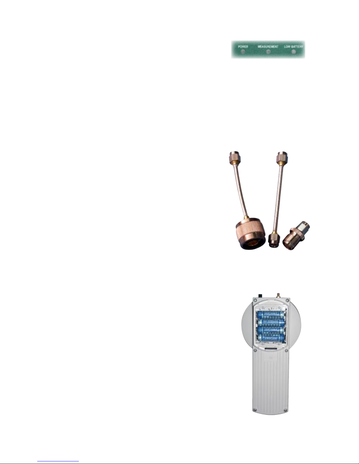
LED STATUS INDICATORS
Power LED indicates when the unit is ON.
Measurement LED indicates when measuring (Bar or
Line graph screen). LED is OFF when in Select Screen
Low Battery indicates when the batteries need a charge
or replacement.
CONNECTION AND USE
Connect the AP to be tested using the supplied SMA
connection kit to the ButterFly RF input connector, the
SMA connector on the top of the ButterFly. Make sure
both the AP and the ButterFly are on If not already
displayed, select either the bar or line graph measurement. If the current RF power indicated by the text
display in the lower left of the display is –40 dbm and
never changes, check the connection between the AP
and ButterFly. If RF power is indicated by this portion
of the display, but no bar or line is displayed, reduce
the threshold using the Down key until the display
becomes active.
BATTERY REPLACEMENT
When the battery low indicator comes on, the batteries must be replaced or recharged. To remove the
batteries, disconnect the ButterFly RF input and turn
the power switch to the off position. Hold the Butterfly
with the bottom facing you, the SMA RF input facing
upward. Locate the tab on the battery cover and using
your finger, gently pull the tab toward the bottom of the
unit until the cover comes away from the unit. Remove
the batteries and replace, observing the battery polarities marked on the plastic of the battery compartment.
Replace the battery cover by positioning the tab on the
bottom of the cover into the slot in the bottom of the
battery compartment. Push on the cover until the tab
on the top clicks back into position. The unit is now
ready to resume use.
Page 3

STARTUP SCREEN
Operation of the Butterfly is straightforward. Insert 4
fresh battery cells into removable pack. Close back up
and power on the Butterfly. The Butterfly will display
the STARTUP SCREEN followed by the MAIN MENU.
MAIN SELECT SCREEN
Use the UP/DOWN buttons to scroll through menu
selections. Push the LEFT button to make a selection
and push the RIGHT button to move back one previous
screen.
2.4 GHZ BAR GRAPH
This screen displays any 2.4 GHz access point’s output in dBm using a horizontal graphical bar. When a
bar graph measurement is started, it will run until the
measurement is changed or the unit is turned off. The
last measurement selected is restored when the unit is
turned back on. The bar graph measurement continually monitors the RF input connected to unit. When a
packet is detected that is above the set threshold, a
bar is displayed whose length is proportional to the
measured signal strength of the packet. The threshold
is marked by the down arrow above the signal strength
bar. This packet threshold is adjusted by pressing the
UP and DOWN keys while the measurement is displayed.
The current signal strength is displayed in
text in the lower left corner of the screen. This signal
strength text is always updated, even if a packet is not
detected. The highest level measured when a packet
is detected is marked by the Up arrow and wavy line
Page 4

below signal strength bar. This indicator stays at the
position of the strongest packet signal until the measurement is changed or restarted.
To view the current dBm value during either the bar
graph or line graph measurement in LARGE Characters,
press the enter key during the measurement. To return
to the graph screen, press the enter key again.
2.4 GHZ LINE GRAPH
This screen displays any 2.4 GHz (802.11b/g & 802.11
FHSS) access point’s output in dBm (vertical) graphing
power over time (hrozontal) in milliseconds (scrolling
from left to right). As with the bar graph when selected,
the line graph will run until changed or the unit is shut
off. If the unit is shut off while displaying a line graph
measurement, the line graph measurement will resume
when the unit is next turned on. The line graph measurement (as the bar graph measurement) continually
monitors the RF input and displays this input when a
packet is detected that is greater then the threshold, in
this screen the threshold is displayed as a dotted line.
To adjust this threshold, press the UP and DOWN keys
while the measurement is displayed. The current RF
power measured during the line graph measurement is
displayed in text in the lower left corner of the display.
As in the Bar graph, this value is always updated, even
if a packet is not detected. For both the bar and line
graph measurements, if the total power displayed in
the lower left corner is changing but no bar or line is
displayed, reduce the packet detect threshold by pressing the DOWN key.
5 GHZ BAR GRAPH
This screen displays any 5 GHz access point’s output
in dBm using a horizontal graphical bar. When a bar
graph measurement is started, it will run until the
measurement is changed or the unit is turned off. The
last measurement selected is restored when the unit is
turned back on. The bar graph measurement continually monitors the RF input connected to unit. When a
Page 5

packet is detected that is above the set threshold, a
bar is displayed whose length is proportional to the
measured signal strength of the packet. The threshold
is marked by the down arrow above the signal strength
bar. This packet threshold is adjusted by pressing the
UP and DOWN keys while the measurement is displayed.
The current signal strength is displayed in
text in the lower left corner of the screen. This signal
strength text is always updated, even if a packet is not
detected. The highest level measured when a packet
is detected is marked by the Up arrow and wavy line
below signal strength bar. This indicator stays at the
position of the strongest packet signal until the measurement is changed or restarted.
5 GHZ LINE GRAPH
This screen displays any 5 GHz (802.11a) access
point’s output in dBm (vertical) graphing power over
time (hrozontal) in milliseconds (scrolling from left to
right). As with the bar graph when selected, the line
graph will run until changed or the unit is shut off. If
the unit is shut off while displaying a line graph measurement, the line graph measurement will resume
when the unit is next turned on. The line graph measurement (as the bar graph measurement) continually
monitors the RF input and displays this input when a
packet is detected that is greater then the threshold, in
this screen the threshold is displayed as a dotted line.
To adjust this threshold, press the UP and DOWN keys
while the measurement is displayed. The current RF
power measured during the line graph measurement is
displayed in text in the lower left corner of the display.
As in the Bar graph, this value is always updated, even
if a packet is not detected. For both the bar and line
graph measurements, if the total power displayed in
the lower left corner is changing but no bar or line is
displayed, reduce the packet detect threshold by pressing the DOWN key.
Page 6

UNIT DATA SCREEN
This screen provides basic information about the
device including the owner, firmware version and
serial number.
ADJUST CONTRAST SCREEN
This screen provides contrast adjustment using the UP
and DOWN buttons to increase and decrease the LCD
screen contrast. Press ENTER (left button) or SELECT
(right button) to exit this screen.
CABLE LOSS
The Cable Loss selection can be used to compensate
for a known cable loss between –1 and –6 dB. Use the
UP and DOWN buttons to select the required cable loss
compensation and press the Enter key to use. Entering
a value of 0 dB for Cable Loss has no effect on the
ButterFly display. This is the shipped factory default
value.
Page 7

BATTERY TIPS
1. Ni-MH batteries do not charge to full capacity the first time they are charged.
2. Ni-MH batteries do not charge to full capacity the first time they are charged after a long period of inactivity. or after a long
period of non-use.
Cause:
When charging Ni-MH batteries for the first time after long-term storage, deactivation of reactants may lead to increased battery
voltage and decreased capacity, (which causes premature termination of charging). Because batteries are chemical products
involving internal chemical reactions, performance deteriorates with prolonged storage. This is normal in Ni-MH batteries.
Resolution:
Ni-MH batteries may not charge to full capacity the first time they are charged, or after a long period of inactivity.
The first-time charge of the Ni-MH Rechargeable Battery Pack should take approximately 2 hours. If the Receiver Dock light
turns green, indicating a full charge, in less than 2 hours, repeat the charge cycle as follows:
First-time Charge:
1. To begin charging, place the instrument on the Charge Dock. Refer to your instrument’s User Guide for details.
2. When the charge light turns green, remove the W-LAN Receiver from the dock and place back on the dock after several
seconds.
3. Repeat steps 1 and 2 three or four times or until the combined charge time is 2 hours.
Subsequent charges of the W-LAN Ni-MH Battery Pack will not require multiple charging cycles unless left uncharged for a long
period of time (greater than 2 months).
Page 8

Networking Basics
Packets and traffic
Information travels across a network in chunks called “packets.” Each packet has a header that tells where
the packet is from and where it’s going, similar to what you write on the envelope when you send a letter.
The flow of all these packets on the network is called “traffic.”
Hardware addresses
Your PC “listens” to all of the traffic on its local network and selects the packets that belong to it by checking for its hardware address in the packet header or MAC (Media Access Control). Every hardware product
used for networking is required to have a unique hardware address permanently embedded in it.
IP addresses
Since the Internet is a network of networks (connecting millions of computers), hardware addresses alone
are not enough to deliver information on the Internet. It would be impossible for your computer to find its
packets in all the world’s network traffic, and impossible for the Internet to move all traffic to every network, your PC also has an IP (Internet Protocol) address that defines exactly where and in what network
it’s located. IP addresses ensure that your local Ethernet network only
receives the traffic intended for it. Like the hierarchical system used to define zip codes, street names,
and street numbers, IP addresses are created according to a set of rules, and their assignment is carefully
administered.
Put another way, the hardware address is like your name; it uniquely and permanently identifies you. But it
doesn’t offer any clues about your location, so it’s only helpful in a local setting. An IP address is like your
street address, which contains the information that helps letters and packages find your house.
Rules for Sending Information (Protocols)
A protocol is a set of rules that define how communication takes place. For instance, a networking protocol may define how information is formatted and addressed, just as there’s a standard way to address an
envelope when you send a letter.
Networking Devices:
Bridges
A bridge joins two networks at the hardware level. This means that as far as other protocols are concerned,
the two networks are the same.
Routers
A router connects two IP networks. In contrast to a bridge, which joins networks at the hardware level, a
router directs network IP traffic based on information stored in its routing tables. A routing table matches
IP addresses with hardware addresses. The router stamps each incoming IP packet with the hardware
address that corresponds to that IP address. As a result, the packet can be picked up by the right computer
on the hardware network.
DNS (Domain Name Server)
Networks (domains) on the Internet have names that correspond to their IP addresses. A Domain Name
Page 9

Server maintains a list of domain names and their corresponding addresses. This is why you can go to
Berkeley’s Web site by entering www.bvsystems.com, instead of the IP address.
Networking Terms:
TCP/IP (Transport Control Protocol/Internet Protocol)
TCP/IP is a collection of protocols that underlies almost every form of communication on the Internet.
DHCP (Dynamic Host Control Protocol)
DHCP is a method of automatically assigning IP addresses. Instead of assigning addresses to individual
users, addresses are assigned by the DHCP server when clients need them. This means that instead of
entering several fields of long addresses, users need only to select DHCP as their configuration method
for IP networking.
PPP (Point-to-Point Protocol)
PPP is the most common protocol for providing IP services over a modem.
NAT (Network Address Translation)
NAT is used to share one IP address among several computers. A device set up as a NAT router uses a collection of “private” IP addresses (in the range 10.0.1.2 to 10.0.1.254 for example) to allow several computers to access the Internet using one “public” IP address. When a computer using a private IP address
requests information from the Internet, the NAT router keeps a record of the computer making the request,
and sends the information to the Internet using its own IP address. When the response comes back from
the Internet, the NAT router forwards the packet to the appropriate computer.
Page 10

Glossary of Acronyms
AC Alternating Current
A/D Analog to Digital converter
AGC Automatic Gain Control
AP Access Point
Applet a small Application
BER Bit Error Rate
BPSK Binary Phase Shift Keying
BSS Basic Service Set
BW Band Width
CDMA Code Division Multiple Access (spread spectrum modulation)
DC Direct Current
D/A Digital to Analog
dB decibel
dBm decibels referenced to 1 milliwatt
DOS Digital Operating System
DSP Digital Signal Processing
DSSS Direct Sequence Spread Spectrum
ESS Extended Service Set
FIR Finite Impulse Response
GHz GigaHertz
IF Intermediate Frequency
I and Q In phase and Quadrature
IBBS Independent Basic Service Set
kHz kiloHertz
LCD Liquid Crystal Display
LO Local Oscillator
MAC Medium Access Control
Mbits Megabits
MHz MegaHertz
NIC Network Interface Card
OFDM Orthogonal Frequency Domain Multiplexing (802.11a)
PC Personal Computer
PCS Personal Communications Service (1.8 to 2.1 GHz frequency band)
PER Packet Error Rate
PN Pseudo Noise
QPSK Quaternary Phase Shift Keying, 4-level PSK
RF Radio Frequency
RSSI Receiver Signal Strength Indicator
SSID Service Set IDentification
UCT Universal Coordinated Time
VAC Volts Alternating Current
VGA Video graphic
WLAN Wireless Local Area Network
Page 11

IMPORTANT SAFETY INSTRUCTIONS
When using your telephone equipment, basic safety precautions should always be followed to reduce the risk of fire, electric
shock and injury to persons, including the following:
1)Read and understand all instructions.
2)Follow all warnings and instructions marked on the product.
3)Unplug this product from the wall outlet before cleaning. Do not use liquid cleaners or aerosol cleaners. Use a damp cloth
for cleaning.
4)Do not use this product near water, for example, near a bath tub, wash bowl, kitchen sink, or laundry tub, in a wet basement,
or near a swimming pool.
5)Do not place this product on an unstable cart, stand, or table. The product may fall, causing serious damage to the product.
6)Slots and openings in the cabinet and the back or bottom are provided for ventilation, to protect it from overheating these
openings must not be blocked or covered The openings should never be blocked by placing the product on the bed, sofa, rug or
other similar surface. This product should never be placed near or over a radiator or heat register. This product should not be
placed in a built-in installation unless proper ventilation is provided.
7) This product should be operated only from the type of power source indicated on the appliance. If you are not sure of the type
of power supply to your home, consult your dealer or local power company.
8)Do not allow anything to rest on the power cord. Do not locate this product where the cord will be abused by persons walking
on it.
9)Do not overload wall outlets and extension cords as this can result in the risk of fire or electric shock.
10)Never push objects of any kind into this product through cabinet slots as they may touch dangerous voltage points or short
out parts that could result in a risk of fire or electric shock. Never spill liquid of any kind on the product.
11) To reduce the risk of electric shock, do not disassemble this product, but take it to a qualified service faciI4 when some
service or repair work is required. Opening or removing covers may expose you to dangerous voltages or other risks. Incorrect
reassembly can cause electric shock when the appliance is subsequently used.
12) Unplug this product from the wall outlet and refer servicing to qualified service personnel under the following conditions:
A) When the power supply cord or plug is damaged or frayed. B) If liquid has been spilled into the product.
C) If the product has been exposed to rain or water.
D) If the product does not operate normally by following the operating instructions. Adjust only those controls, that are covered
by the operating instructions because improper adjustment of other controls may result in damage and will often require exten-
Page 12

sive work by a qualified technician to restore the product to normal operation.
E) If the product has been dropped or the cabinet has been damaged. F) If the product exhibits a distinct change in perfor-
mance.
13)Avoid using the product during an electrical storm. There may be a remote risk of electric shock from lightning.
14)Do not use the telephone to report a gas leak in the vicinity of the leak.
INSTALLATION INSTRUCTIONS
1. Never install telephone wiring during a lightning storm.
2. Never install telephone jacks in wet locations unless the jack is specifically designed for wet locations.
3. Never touch uninsulated telephone wires or terminals unless the telephone line has been disconnected at the network inter-
face.
4. Use caution when installing or modifying telephone lines.
INSTRUCTION FOR BATTERIES
CAUTION: To Reduce the Risk of Fire or Injury to Persons, Read and Follow these Instructions:
1. Use only the type and size of batteries mentioned in owner’s manual.
2. Do not dispose of the batteries in a fire. The cells may explode. Check with local codes for possible special disposal
instructions.
3. Do not open or mutilate the batteries. Released electrolyte is corrosive and may cause damage to the eyes or skin. It
may be toxic if swallowed.
4. Exercise care in handling batteries in order not to short the battery with conducting materials such as rings, bracelets,
and keys. The battery or conductor may overheat and cause burns.
5. Do not attempt to recharge the batteries provided with or identified for use with this product. The batteries may leak
corrosive electrolyte or explode.
6. Do not attempt to rejuvenate the batteries provided with or identified for use with this product by heating them. Sudden
release of the battery electrolyte may occur causing burns or irritation to eyes or skin.
7. When replacing batteries, all batteries should be replaced at the same time. Mixing fresh and discharged batteries
could increase internal cell pressure and rupture the discharged batteries. (Applies to products employing more than one sepa-
rately replaceable primary battery.)
8. When inserting batteries into this product, the proper polarity or direction must be observed. Reverse insertion of bat-
teries can cause charging, and that may result in leakage or explosion. (Applies to product employing more than one separately
replaceable primary battery.)
9. Remove the batteries from this product if the product will not be used for a long period of time (several months or more)
since during this time the battery could leak in the product.
10. Discard “dead” batteries as soon as possible since “dead” batteries are more likely to leak in a product.
11. Do not store this product, or the batteries provided with or identified for use with this product, in high-temperature
areas. Batteries that are stored in a freezer or refrigerator for the purpose of extending shelf life should be protected from con-
densation during storage and defrosting. Batteries should be stabilized at room temperature prior to use after cold storage.
Page 13

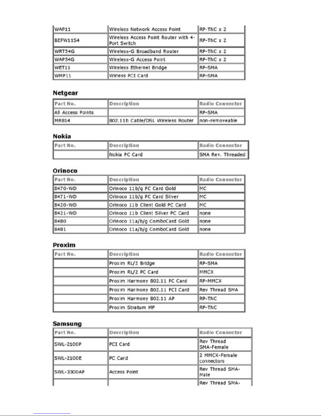
Access Point Connector Guide
Page 14

Page 15

Page 16
Page 17

Page 18

Page 19
 Loading...