

Page 1
Berkeley Audio Design® Alpha DAC® Reference Series 3
The Alpha DAC Reference Series 3 has breakthrough technology that redefines the potential
of digital audio quality. In addition to its unprecedented PCM audio quality, the Alpha DAC
Reference Series 3 also features MQA Rendering of unequaled audio quality. Please take a
few minutes to familiarize yourself with this User Guide before connecting power to the Alpha
DAC Reference Series 3.
INSTALLATION
The Alpha DAC Reference Series 3 should be installed in a space with several inches of
clearance above, behind and on both sides of the chassis to provide adequate ventilation.
Avoid placement directly above other equipment that produces significant heat. NOTE: Due to
the very high thermal mass of the Alpha DAC Reference Series 3, please allow 12 hours
after first powering on before performing critical listening.
Power Connection
The Alpha DAC Reference Series 3 is designed to run continuously when connected to AC
mains power to maximize audio fidelity. There is no power switch and as soon as AC power is
connected the unit is powered on. Units for sale in the United States are set internally for
120VAC operation. Your Alpha DAC Reference Series 3 dealer can select 240VAC operation
for use outside of the United States by resetting an internal switch in the power supply. NOTE:
If 240VAC operation is selected the internal FUSE MUST BE CHANGED from a .40 Amp
Slow Blow (Littelfuse 0215.400HXP) for 120VAC to a .20 Amp Slow Blow (Littelfuse
0215.200HXP) for 240VAC. If the fuse fails it must be replaced with the same value and type.
Failure to do so will void the warranty.
Signal Connections
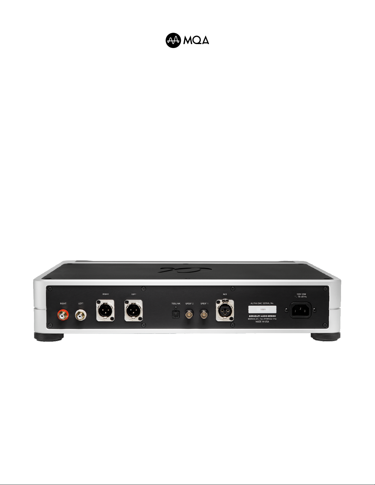
Alpha DAC Reference Series 3 Rear Panel
The Alpha DAC Reference Series 3 has four two channel digital signal inputs: AES - XLR
connector, 110Ω termination; SPDIF1 - BNC connector, 75Ω termination; SPDIF2 - BNC
connector, 75Ω termination; TOSLINK - optical connector.
High quality cables with the correct impedance for each input should be used. For the best
possible audio fidelity only one input at a time should be fed with an active signal.
The Alpha DAC Reference Series 3 has four analog signal outputs - RIGHT and LEFT
balanced on pin 2 positive XLR connectors and RIGHT and LEFT unbalanced on RCA
connectors. All outputs are always active and may be used simultaneously. IR remote control
of all functions including volume and balance allows direct connection to power amplifiers. The
analog outputs are designed to drive long cable lengths and connecting directly to a power
amplifier avoids any loss of fidelity from routing signals through a preamplifier.
1
Page 2
Note: If oversized, “audiophile” type input or output cables are used, especially those that are
very stiff or heavy, care should be taken to properly support them to avoid putting excessive
strain on the panel connectors.
OPERATION
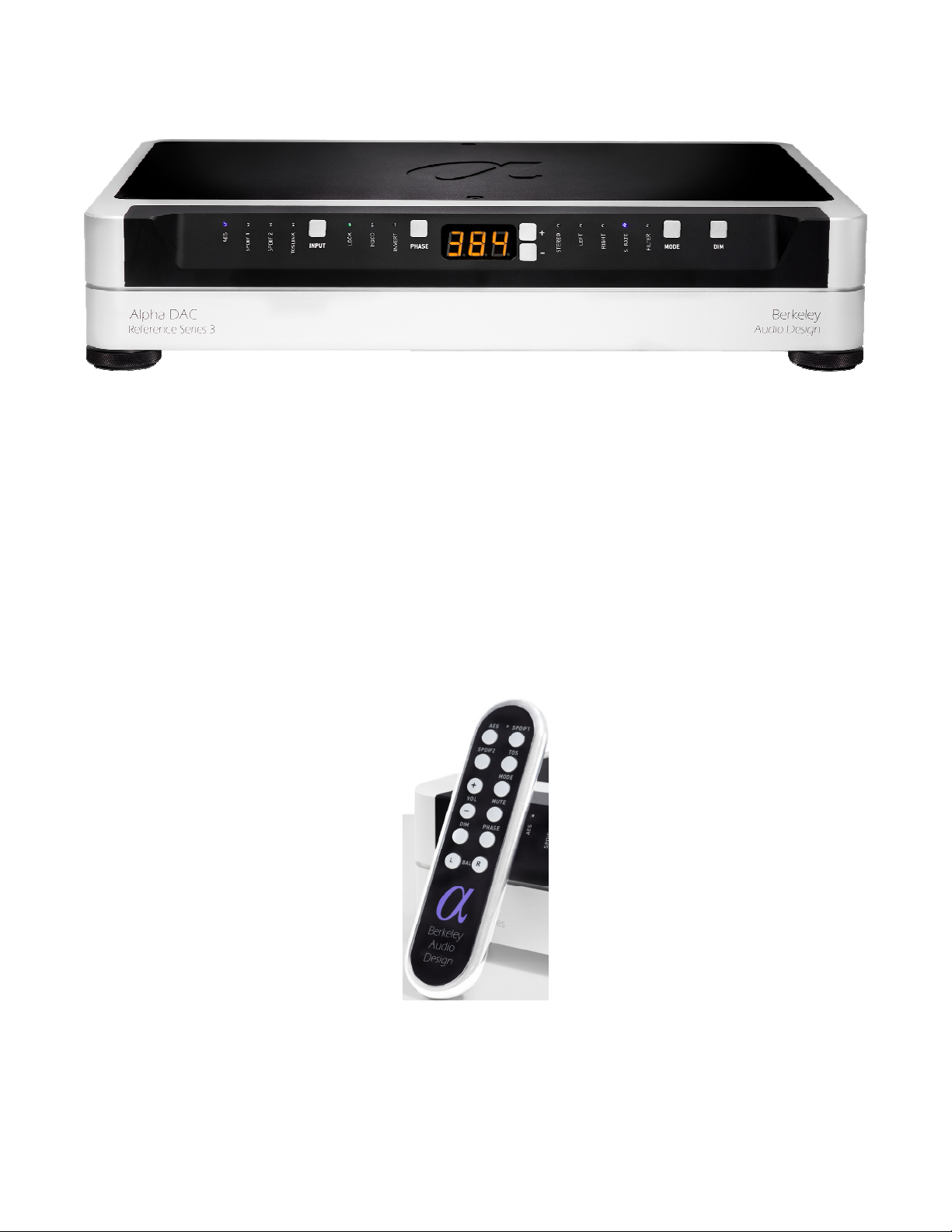
Alpha DAC Reference Series 3 Front Panel
Front Panel Controls & Indicators
• AES, SPDIF1, SPDIF2 and TOSLINK LED’s indicate selected input
• Input button selects AES, SPDIF1, SPDIF2 or TOSLINK inputs
• LOCK LED - amber indicates input signal lock, green indicates Precision Clocking
• HDCD LED indicates HDCD code is detected
• PHASE button sets absolute phase
• INVERT LED indicates inverted absolute phase
• 3 digit LED display of STEREO volume, LEFT & RIGHT gain, Sample RATE,
FILTER type, MQA data, and MUTE
• + & − buttons set volume level and select Filter type
• MODE button selects Stereo, Left, Right, Sampling Rate and Filter display modes
• DIM button selects four different display brightness levels
Alpha DAC Reference Series 3 Remote Control
The remote control has similar controls to the front panel except for the addition of L & R
balance buttons, dedicated AES, SPDIF1, SPDIF2 and TOS input select buttons and a MUTE
button. Also, the + & − buttons on the remote control only adjust volume. Pushing the MODE
button momentarily displays the MQA original sample rate if there is an MQA signal, then
balance (if offset) and volume in all display modes and at all display brightness levels. If the
MODE button is pushed and held, balance is reset to 0.
2
Page 3

Many Alpha DAC Reference Series 3 functions such as input sampling rate selection, MQA
rendering and HDCD decoding occur automatically. Once the Alpha DAC Reference Series 3
is properly installed the most commonly used controls are volume, balance (remote only), mute
(remote only) and input select.
Volume Adjustment
Volume is adjusted in 0.1dB steps by pushing the + or − buttons on the remote control or front
panel in STEREO or Sample RATE modes. Pushing and holding down either of the buttons
adjusts the volume level more rapidly. Volume level is shown on the 3 digit display in dB. 60.0
is maximum level and 00.0 is minimum level. 54.0 is the recommended level if a preamplifier is
used after the Alpha DAC Reference Series 2. When AC power is removed the volume level
resets to 25.0 for safety. Note: In LEFT, RIGHT or FILTER modes the front panel + & −
buttons perform different functions. Please see detailed information on this page and page 4.
Balance Adjustment
Balance is adjusted in 0.1dB steps by pushing the L and R buttons on the remote control.
Pushing and holding down either of the buttons adjusts balance more rapidly. Balance is
meant to be a program dependent setting not a system set up adjustment, so selecting a
different input resets balance to 0. If balance is offset to one channel, the higher channel
volume is displayed when adjusting volume.
Left & Right Gain
Left & right gain is adjusted in 0.05dB steps by selecting LEFT or RIGHT display modes and
pushing the front panel + or − buttons. Left & right gain is displayed with 3½ digit resolution. A
decimal point is added to the right of the third digit to indicate .05dB. Note: Unlike the L & R
balance controls on the remote control, left & right gain are fine resolution adjustments for
system set up and do not reset when inputs are changed. If the left & right gains are different,
the higher channel volume is displayed when adjusting volume.
Output Muting
Pushing the MUTE button on the remote control mutes the analog outputs. Pushing the MUTE
button again or pushing the + button on the remote control or front panel un-mutes the outputs.
When the outputs are muted a decimal point appears following the leftmost digit of the 3 digit
display.
Input Selection
Inputs are selected by pushing the button for the desired input on the remote control or by
repeatedly pushing the Input button on the front panel until the LED for the desired input lights.
The four digital inputs are: AES - female XLR connector, 110Ω termination; SPDIF1 - BNC
connector, 75Ω termination; SPDIF2 - BNC connector, 75Ω termination; TOSLINK - Toslink
optical connector.
Absolute Phase
Pushing the PHASE button on the remote control or front panel inverts absolute phase,
pushing the PHASE button again returns absolute phase to normal. The INVERT LED lights
when absolute phase is inverted.
Display Mode
Pushing the front panel MODE button repeatedly selects STEREO volume, LEFT gain, RIGHT
gain, Sample RATE, and FILTER display modes for the 3-digit display. Pushing and holding
down the MODE button steps through all display modes.
3
Page 4

Sample Rate
S. RATE is the default display mode and displays the sampling rate of the digital input signal
with 3½ digit resolution. If the sample rate rounds to between the 3 displayed digits, a decimal
point is added to the right of the third digit; 44.056kHz = 44.0., 176.4kHz = 176.. Adjusting
volume or balance in S. RATE display mode momentarily displays volume or balance. When
an MQA Core decoded input signal is present, MQA is displayed instead of the sampling rate.
Digital Filter Selection
For the best possible audio fidelity the default interpolation filter, Filter 1 (1.16 or 1.24)
should be used. Filter 2 (2.16 or 2.24) is a minimum phase type with minimum pre-ringing.
Digital interpolation filters 1 or 2 can be selected by selecting the Filter display mode and
pushing the front panel + or − buttons. The filter selection made for each sampling rate is
stored independently in memory.
At 44.1kHz only (the sampling rate of Red Book standard compatible HDCD encoded CD’s)
there are 16-bit LSB and 24-bit LSB HDCD code detect versions of each filter, e.g. 1.16 &
1.24. The main difference between the .16 and .24 versions of the 44.1kHz filters is the bit the
filter looks for HDCD LSB code in. In all other ways, except for peak output level, they are
identical. (See HDCD below). All other sampling rates have .24 24-bit LSB HDCD code detect
versions only.
MQA
When a valid MQA Core decoded signal is present on the selected digital input, MQA is
displayed on the 3 digit LED display instead of the input signal sample rate and MQA
Rendering is performed. Streaming applications like Tidal should NOT be set to Passthrough
MQA which turns off MQA Core decoding that is required for MQA Rendering. Momentarily
pushing the MODE button on the remote control temporarily shows the MQA original sample
rate on the 3 digit LED display.
HDCD
The HDCD LED lights when HDCD code is detected in the LSB of the digital input signal and
HDCD decoding is automatically performed. With 44.1kHz sampling rate signals 16-bit LSB
HDCD code is detected by default, e.g. filter 1.16. 24 bit LSB, 44.1kHz HDCD code detection
can be selected in Filter display mode, e.g. filter 1.24. At sampling rates other than 44.1kHz
only 24 bit LSB HDCD code is detected and only 24-bit LSB HDCD code detect filters ending
in .24 are provided. Note: Selecting 24 bit LSB HDCD code detection at 44.1kHz turns off
HDCD amplitude decoding and increases output level by 6dB.
Display Dim
Pushing the Dim button on the remote control or front panel adjusts the display brightness.
Power On/Off Sequence
If the analog signal outputs of the Alpha DAC Reference Series 3 are connected directly to
power amplifiers it should be powered on for 15 seconds or longer before the power amplifiers
are powered on. Before disconnecting power to the Alpha DAC Reference Series 3 the power
amplifiers should be powered off first. The Alpha DAC Reference Series 3 is designed to
power on and off without producing output noises that could damage power amplifiers or
loudspeakers. However, this power on and off sequence should be followed for maximum
protection of associated components.
Upgrading Firmware
Alpha DAC Reference Series 3 firmware is upgradeable by playing a special encrypted WAV
file through any digital signal input. When the Alpha DAC Reference Series 3 is powered on
the current firmware version is displayed.
4
Page 5

SPECIFICATIONS
• Input sampling rate: 32kHz to 192kHz
• Ultra low phase noise Precision Clocking at 44.1kHz, 48kHz, 88.2kHz, 96kHz, 176.4kHz
and 192kHz sampling rates ± 100 ppm
• Input word length: 24-bit
• Two channel analog stereo outputs: XLR balanced with pin 2 positive and RCA
unbalanced
• Digital Inputs: AES - XLR, 110Ω; SPDIF1 - BNC, 75Ω; SPDIF2 - BNC, 75Ω;
TOSLINK – Toslink optical connector
• MQA rendering automatically detects MQA Core decoded signals and performs MQA
Rendering to MQA original sample rates from 44.1kHz to 384kHz and above
• HDCD decoding detects 16-bit flag at 44.1kHz or 24-bit flag at all sampling rates
• Multiple digital filter options
• Balanced analog output level: +18dBu (6.15Vrms) maximum = output level 60, +12dBu
(3.1Vrms) = output level 54, or lower recommended
• Unbalanced analog output level: 3.25Vrms maximum = output level 60, 2Vrms = output
level 54, or lower recommended
• Digital volume & balance control: 0.1dB/step with .05dB/step L/R gain trim, 60dB range
• Frequency response at ≥ 88.2kHz sampling rates: ± 0.1dB from < 0.1Hz to 35 kHz,
- 3dB at 59kHz for 176.4kHz and 192kHz sampling rates
• Distortion at recommended levels: all products ≤ -120dBFS
• THD+N at maximum level: < -110dBFS
• Firmware field upgradeable through signal inputs
• Enclosure dimensions: 3.5”H X 17.5”W x 12.5”D
• Weight: 30 lbs.
• Mains power: 100/120/240VAC, 50/60Hz
• Power consumption: 25W
If you have questions or encounter an issue not covered in this User Guide, please contact
your Berkeley Audio Design Alpha DAC Reference Series 3 dealer.
Or you may contact Berkeley Audio Design by email at: [email protected] or by
phone at: 510-277-0512.
This product is manufactured under license from MQA Limited. The MQA logo is a trade mark
of MQA Limited.
Certain intellectual property rights of Microsoft protect this product. Use or distribution of such
technology outside of this product is prohibited without a license from Microsoft.
© 2019 Berkeley Audio Design, LLC
5
 Loading...