

Page 1

User manual version 1.5
YORKIE-PROYORKIE-PRO
Page 2

Table of Contents
Included in the box......................................................................................................................................................................... 2
Unit Charging and Runtime............................................................................................................................................................. 2
Main Measurement......................................................................................................................................................................... 3
Yorkie-Pro Navigation Tree.............................................................................................................................................................. 4
Features and Navigation................................................................................................................................................................. 5
Data Logging.................................................................................................................................................................................. 5
Main Menu..................................................................................................................................................................................... 5
Data Snapshot............................................................................................................................................................................. 5
Battery Status................................................................................................................................................................................. 5
Cellular Measurements................................................................................................................................................................... 6
Cellular Direction Finding............................................................................................................................................................... 6
Wi-Fi Measurements....................................................................................................................................................................... 7
Wi-Fi Direction Finding................................................................................................................................................................... 8
Bluetooth Measurements................................................................................................................................................................ 9
Bluetooth Direction Finding............................................................................................................................................................ 10
Frequency Analysis........................................................................................................................................................................ 11
Main Menu.................................................................................................................................................................................... 12
Vibrarting Alert.............................................................................................................................................................................. 12
Audible Alert.................................................................................................................................................................................. 12
RF Scan Persistence........................................................................................................................................................................ 12
GPS Status...................................................................................................................................................................................... 12
Battery Status................................................................................................................................................................................. 13
Select Country................................................................................................................................................................................. 13
Unit Information............................................................................................................................................................................. 14
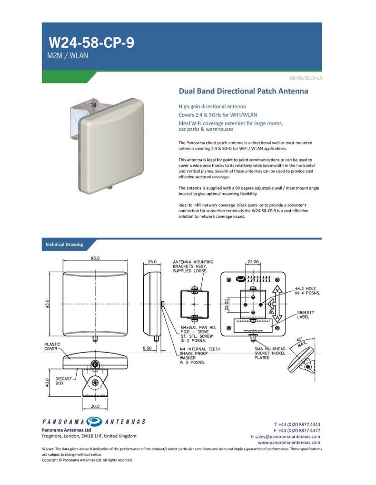
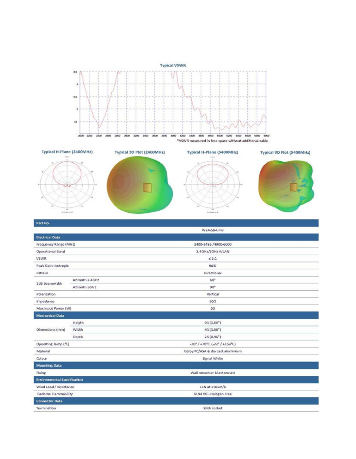
Dual Band Directional Pattch Antenna Specifications....................................................................................................................... 15
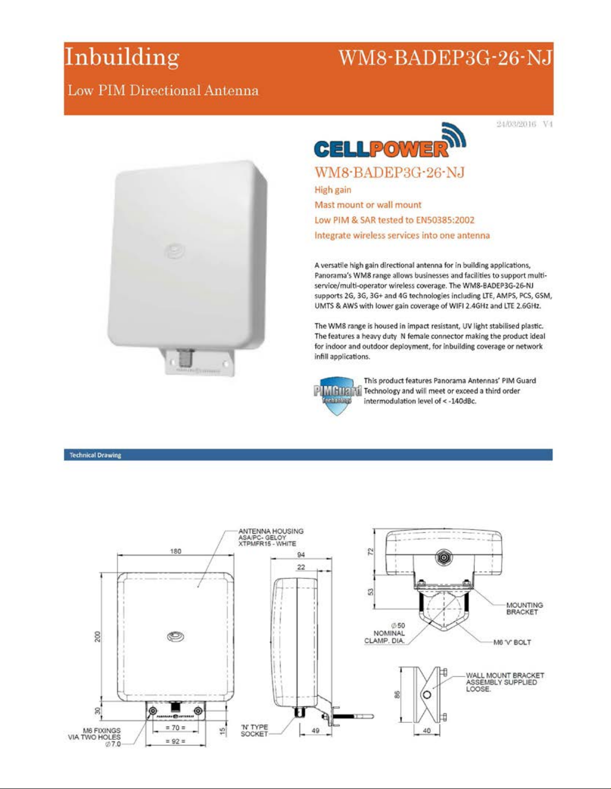
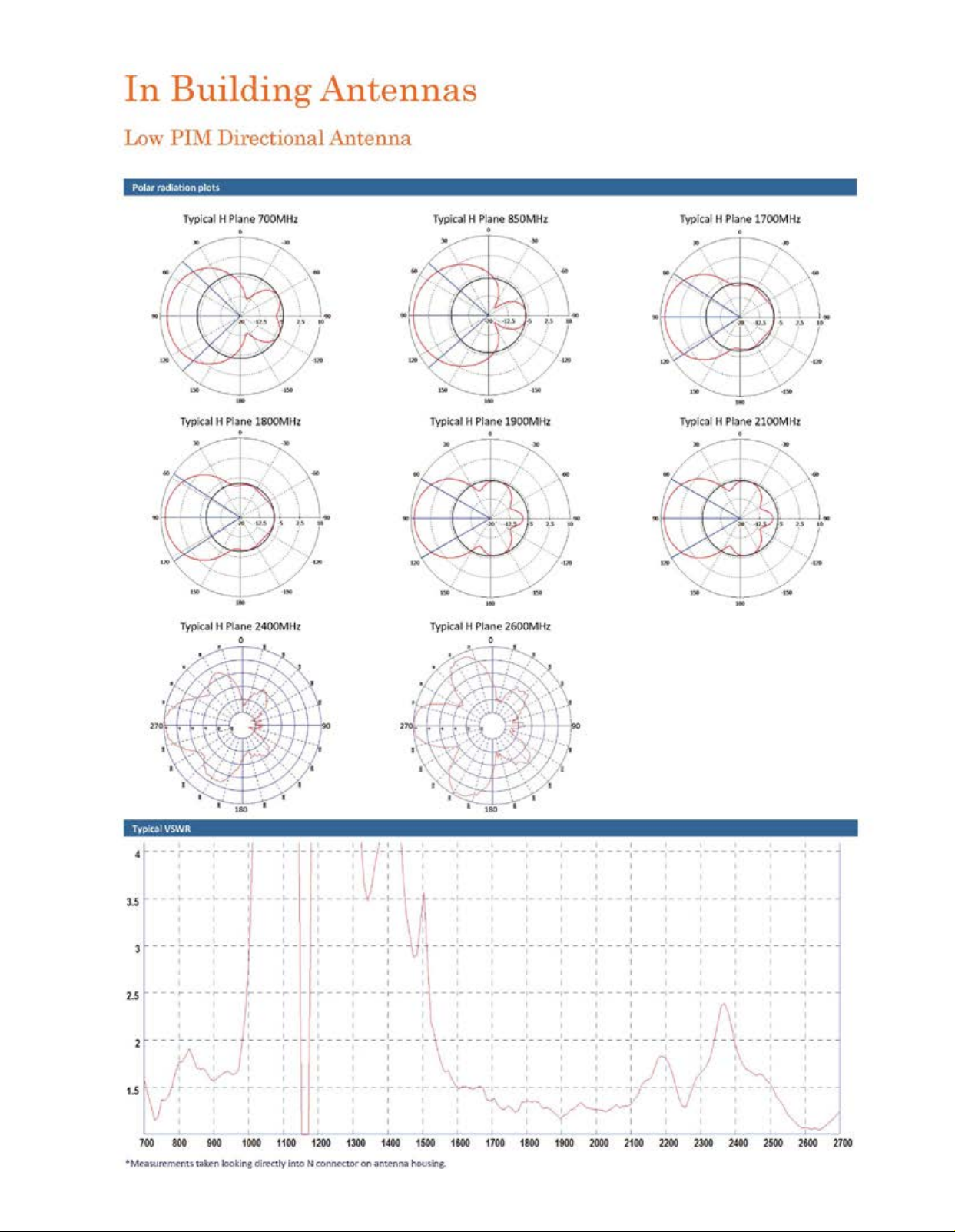
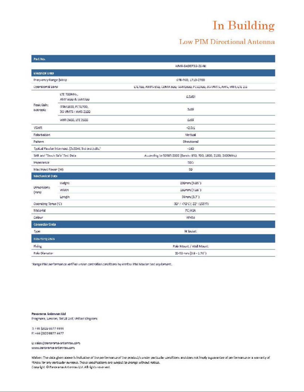
Low Pim Directional Antenna Specifications.................................................................................................................................... 17
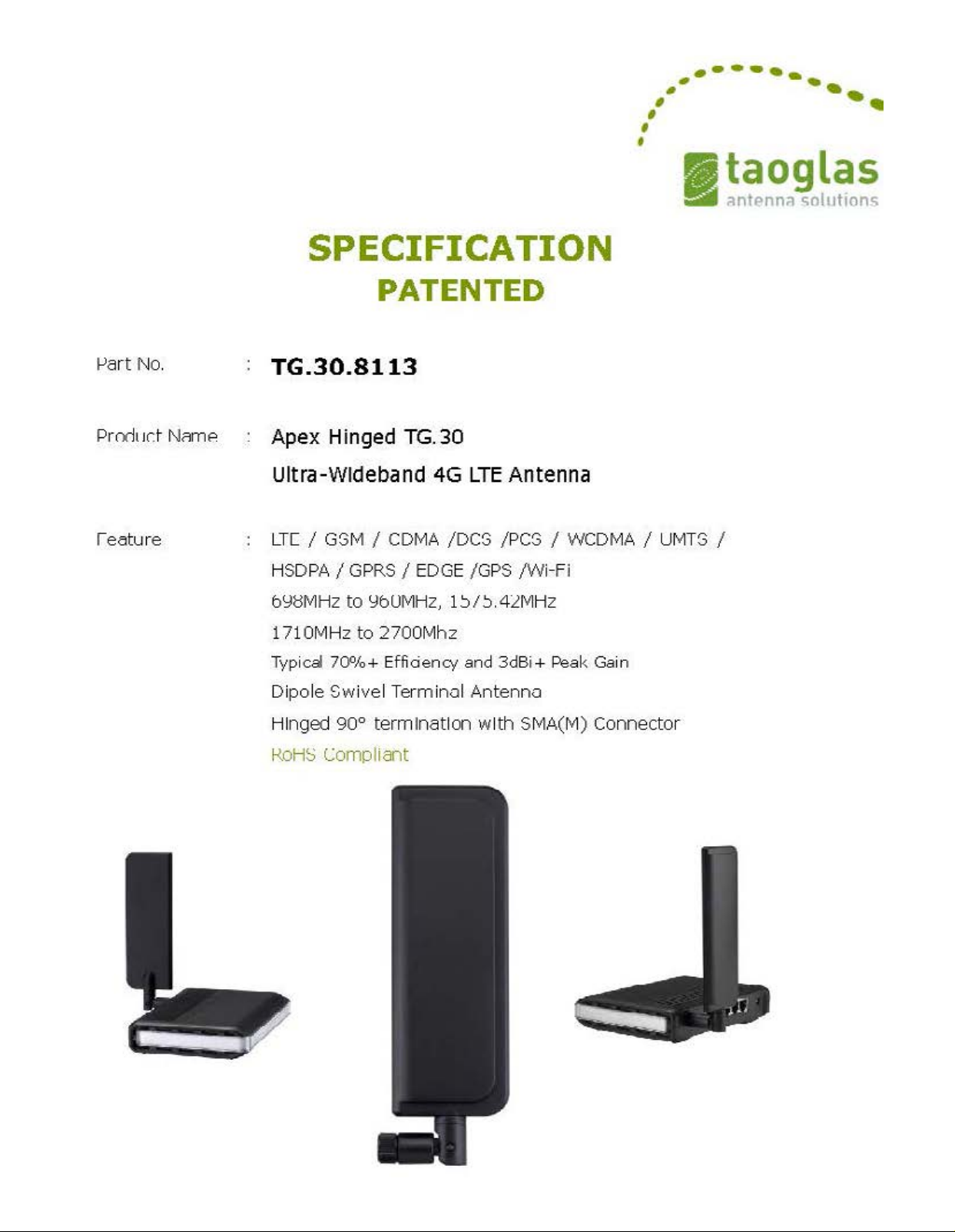
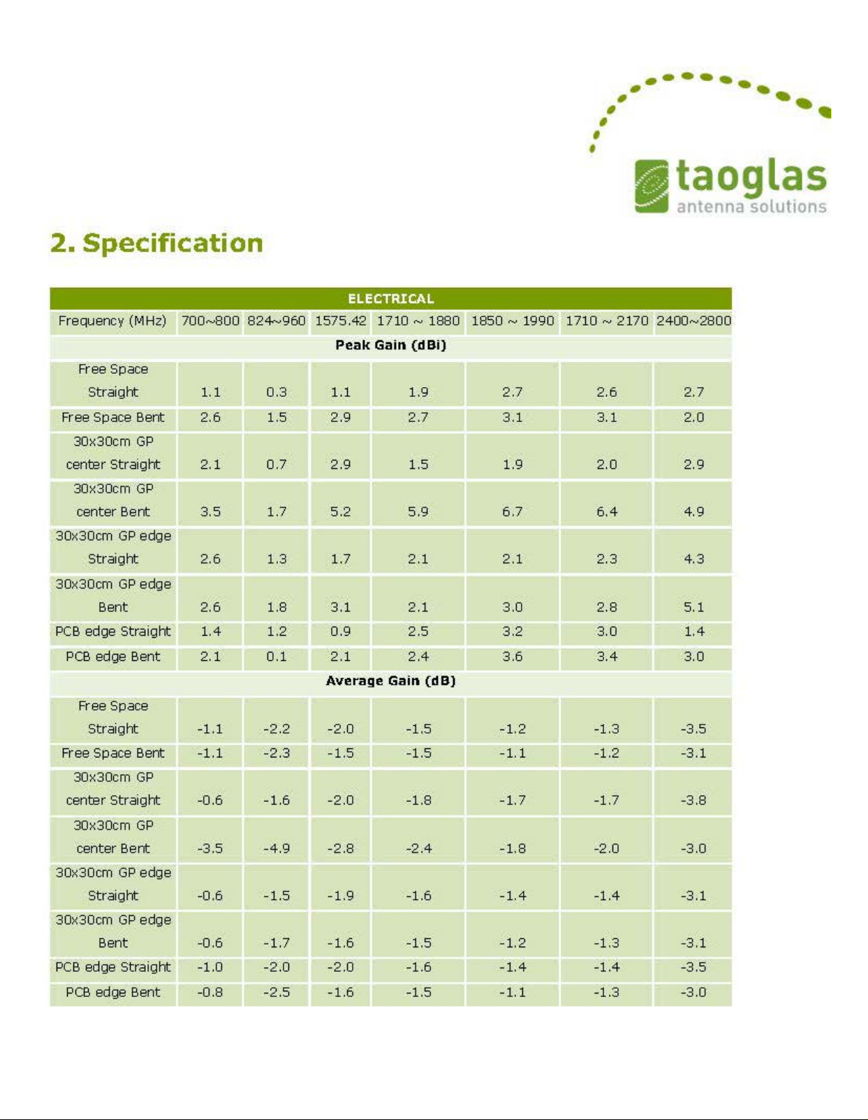
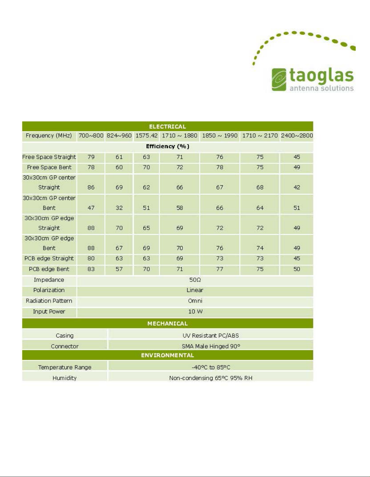
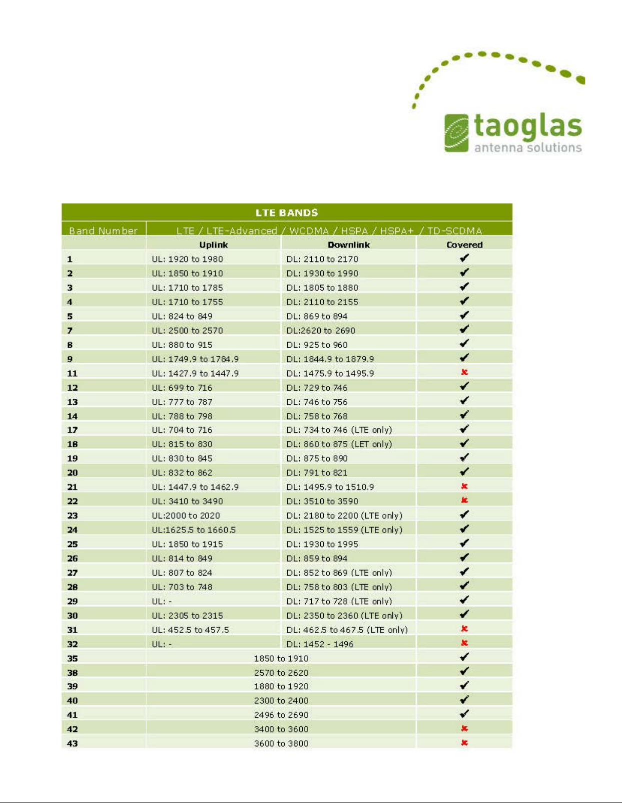
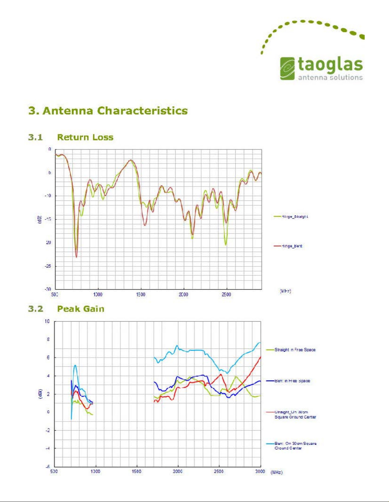
Omni Directional Ultra Wideband Paddle Antenna Specifications.................................................................................................... 20
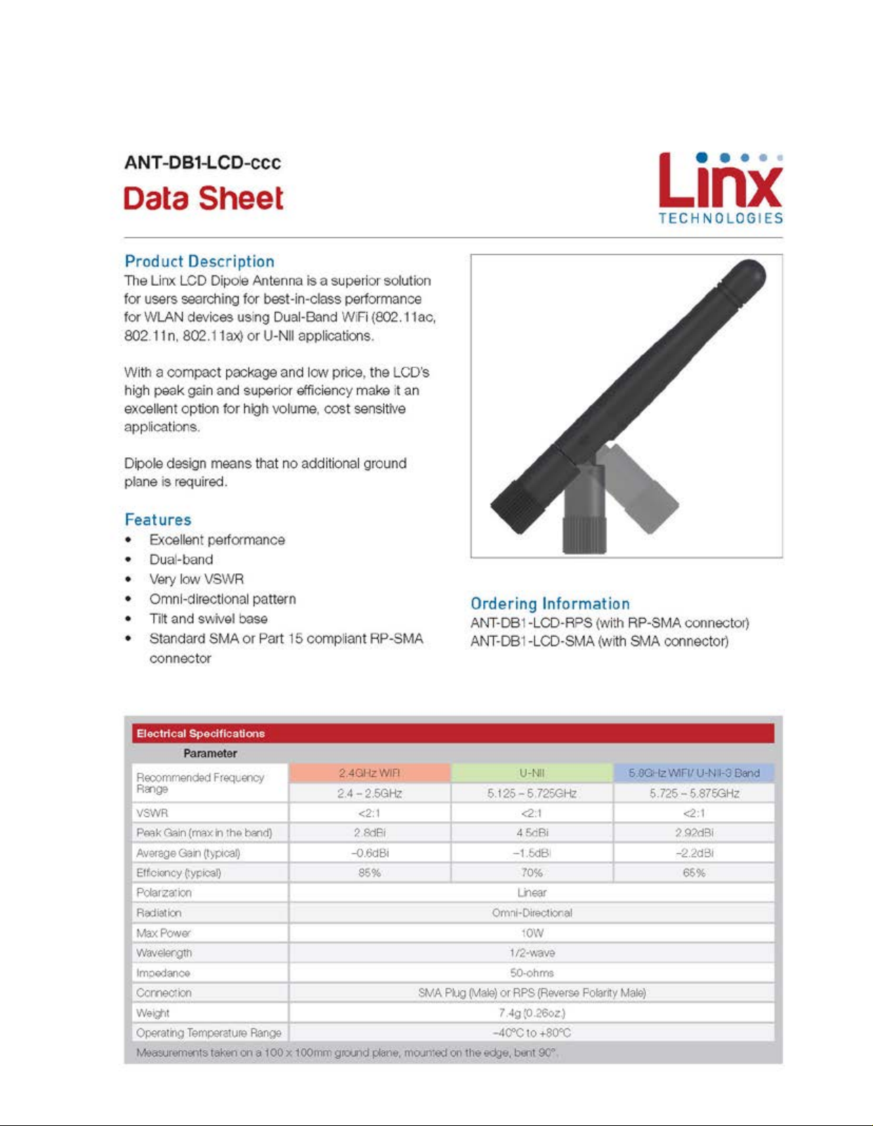
Omni Directional 2.4/5.8 GHz Antenna Specifications.................................................................................................................... 25
Page 1
Page 3
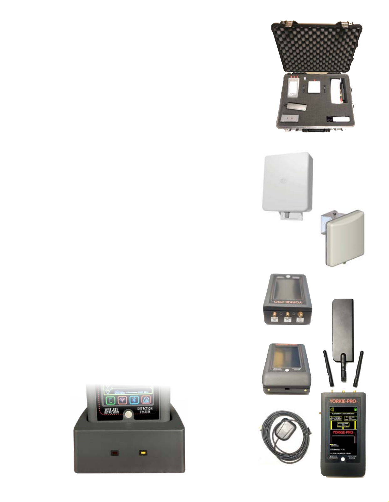
Yorkie-Pro ships inside its own rugged Pelican carrying case along with all accessories to get you
going right away.
Included in box:
Pelican hard carrying/shipping case with space for accessories
Yorkie-Pro unit
charging base
AC power adapter with 110V AC power cable
USB-A to USB Mini 6’ cable
2.4 / 5.8 GHz Wi-Fi/BT/BLE SMA omni-directional antenna
650-3000 MHz CW SMA omni-directional antenna
4.9-5.9 GHz CW SMA omni-directional antenna
2.4 / 5.8 GHz Wi-Fi/BT/BLE SMA directional patch antenna with 18” cable
650-3000 MHz CW SMA directional antenna includign 18” cable
Before you start, completely charge up your Yorkie-Pro using the supplied AC/DC transformer
and charging base. Note that the mini-USB port is for BVS factory use unless specied by your
authorized BVS sales engineer or reseller.
Power up your Yorkie-Pro using the white, round button on the front of the unit just below the
screen. The unit will immediately begin scanning but allow at least one minute after all antennae are attached for complete measurements of all nearby wireless energy.
You may power down Yorkie-Pro at any time by simply holding in the same round, white button
for a few seconds and you see the screen power back down.
UNIT CHARGING and RUNTIME
Yorkie-Pro takes approximately 5 hours to charge fully when using the supplied charging cradle.
Yorkie-Pro runtime is approximately 6 hours assuming a full charge on a full charge/discharge
cycle. All battery performance degrades over time but if your typical Yorkie-Pro runtime is noticebly lower than 6 hours, you may need to disharge and recharge your Yorkie-Pro fully. Please
consult with BVS support for full details on this procedure.
Page 2
Page 4
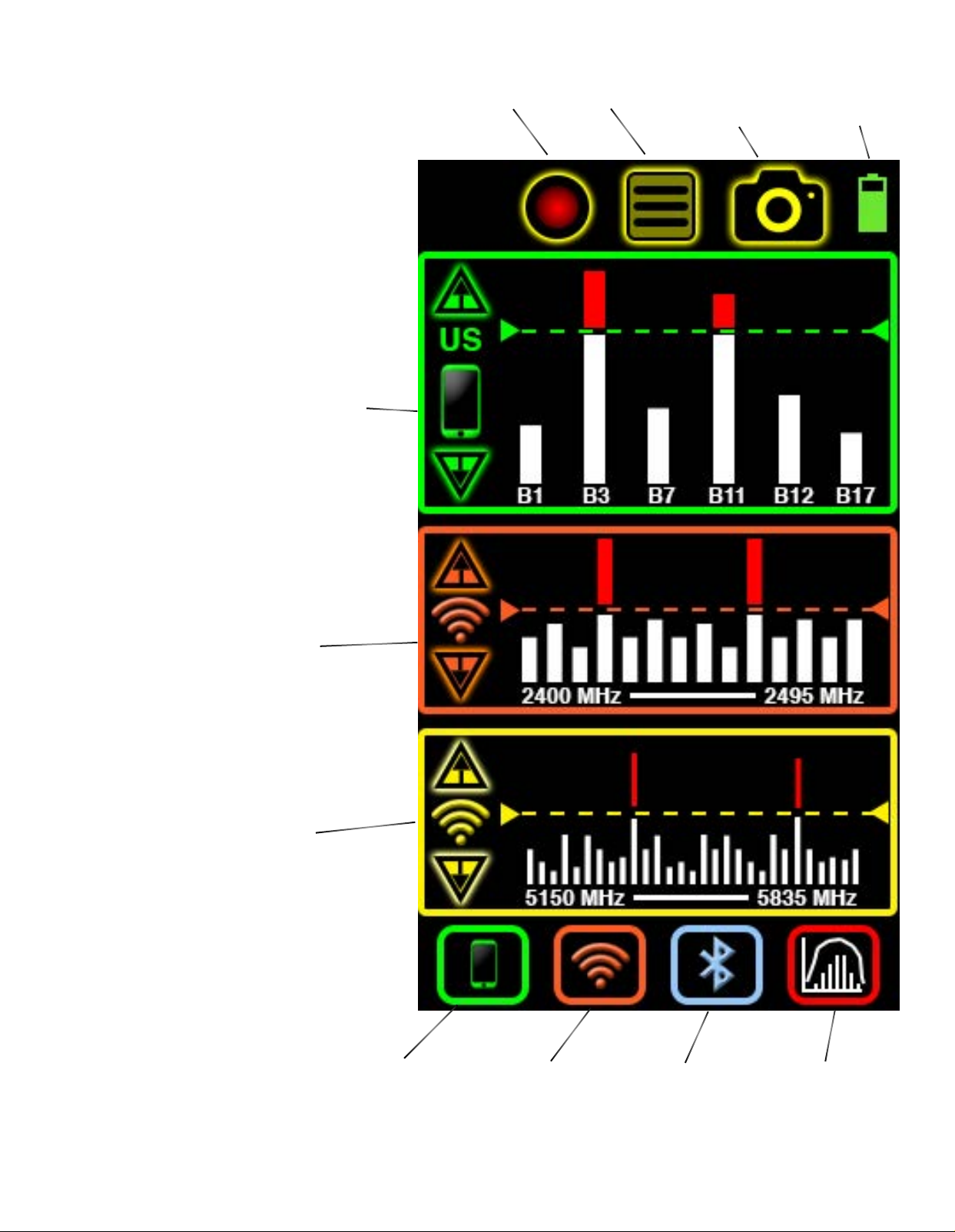
MAIN MEASUREMENT
This is the rst and main Yorkie-Pro measurement
screen users will see allowing a quick glance of all
wireless activity. In this screen, independent thresholds can be set for cellular and Wi-Fi bands. Users can
also drill down to one or all lists of all detected devices. Logging data, data snapshots and main menus
can all be accessed from here too. A frequency and
time domain analysis screen can only be accessed
from here.
Top 6 strongest cellular frequencies are listed by channel
number. Use UP/DOWN arrows to adjust threshold. Red signal
strength bars indicate level above threshold and will trigger
vibrating alerts depending upon alert settings. ‘US’ indicates
United States cellular bands will only be detected. Yorkie-Pro
ships from the factory with country’s RF bands as indiacted
by the customer but you can change to your country of choice
in the Main Menu settings. Please consult with BVS sales or
support staff to verify that your unit can support your country
before purchasing and also before you attempt to change the
country in the MAIN MENU.
Records all data shown
on screen for export
and review onto PC
Navigates to
Main Menu for
all settings.
Saves a single data
snapshot and timestamps for export
and review onto PC.
Battery level indicator. Navigate to battery settings in main
menu for more info.
Displays entire 2.4 GHz Wi-Fi 14 channel band. Use
UP/DOWN arrows to adjust threshold. Red signal
strength bars indicate level above threshold and will
trigger vibrating alerts depending upon alert settings.
Displays entire 5 GHz Wi-Fi band. Use UP/DOWN arrows to adjust threshold. Red signal strength bars indicate level above threshold and will trigger vibrating
alerts depending upon alert settings.
Push this button
to access cellular band and
compare top 3
strongest signals
received.
Push this button to access
a list of all Wi-Fi access
points by signal strength
and more information.
Page 3
Push this button to access a
list of all Bluetooth and BLE
(Bluetooth Low Energy) access points by signal strength
and more information.
Push this button to
access the frequency
analyzer screen which
displays frequency and
time domain graphs in
2.4 GHz band only.
Page 5
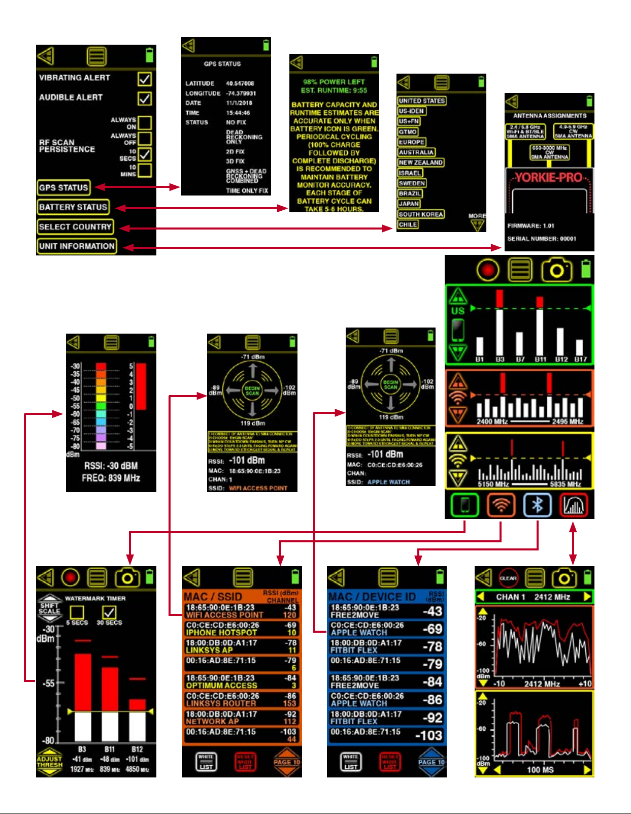
Yorkie-Pro Navigation Tree
Page 4
Page 6
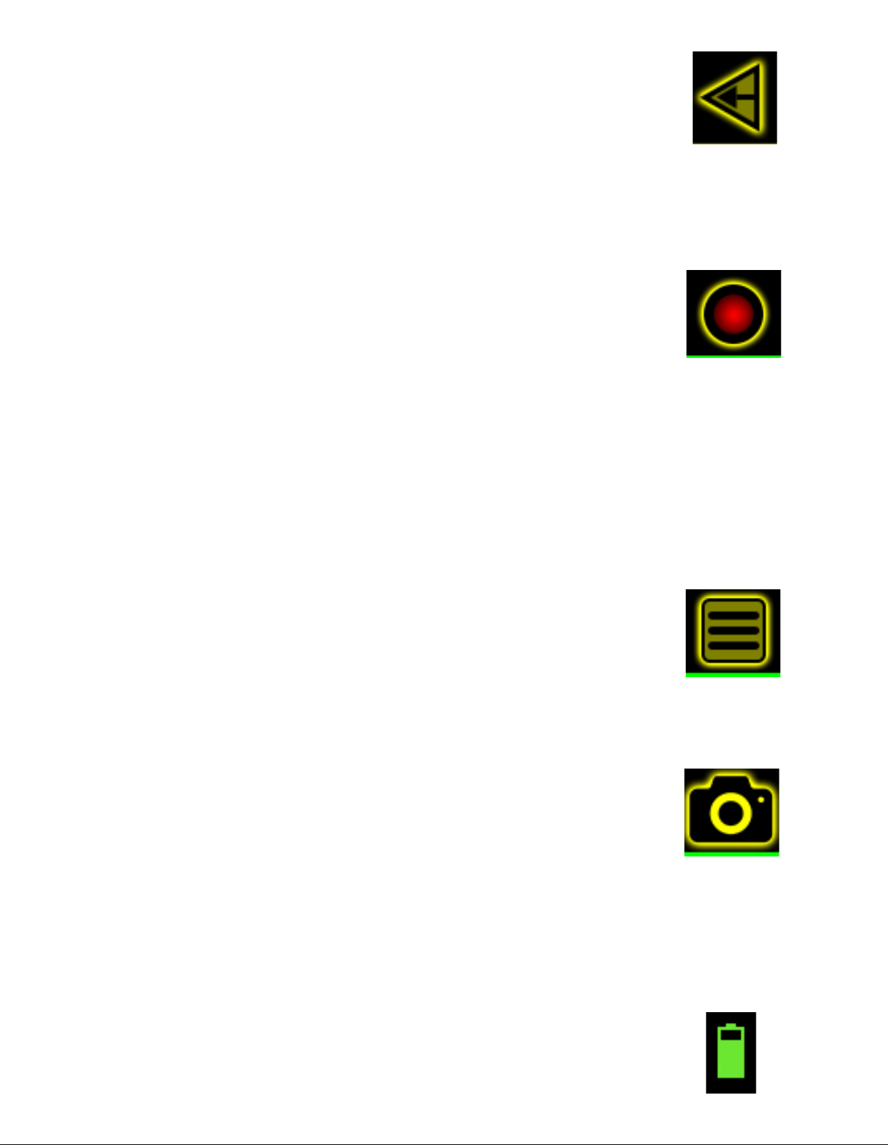
FEATURES & NAVIGATION
BACK ARROW
Use this arrow usually located on the upper left of the screen to navigate back to the previous
screen. If it does not appear, then there is no previous screen.
DATA LOGGING
Touch this icon to begin logging data. The icon ashes to indicate measurements currently being
seen on screen are also being recorded to the unit’s internal ash storage. All data logs are time
stamped using the Yorkie-Pro’s internal GPS for precise time and positioning. Simply touch the
icon again to stop data logging.
Internal storage allows for 5 unique data logging sessions at approximately 13MB per log le.
Depending upon the screen being logged, the resulting data can be logged for a range of time.
This data can then be downloaded from Yorkie-Pro to a PC for futher analysis in any standard
spreadsheet application. Check with your BVS sales or support representative for more information.
MAIN MENU
Touch this menu icon to enter the MAIN MENU settings from any screen. If you do not see this
icon at the top of the screen, you are already in the MAIN MENU. Continue further into this user
manual for a detailed breakdown of all settings.
DATA SNAPSHOT
Touch this camera icon to take a quick data snapshot of the on-screen data at anytime. Note:
this does not take a screen image but rather it captures all visible measurements into a data
snapshot. Yorkie-Pro can store up to 256 snapshots internally.
This allows for convenient data points that can easily be integrated into a spreadsheet or report.
All snapshots are time stamped using the Yorkie-Pro’s internal GPS for precise time and positioning. These snapshots can then be downloaded from Yorkie-Pro to a PC for futher analysis in any
standard spreadsheet application.
BATTERY STATUS
This battery icon indicates the unit’s remaining power at a glance. For estimated runtime and
battery details, choose BATTERY STATUS in the MAIN MENU.
Page 5
Page 7
CELLULAR MEASUREMENTS
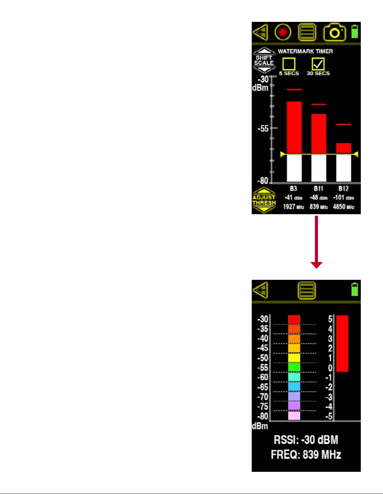
This screen displays the 3 highest cellular signal strength measurements in dBm, frequency and
cellular channel allocation from moment to moment. This means that the top 3 strongest signals
displayed can quickly change if any newer, stronger cellular signals are then detected. This allows users to dynamically sweep the area for the strongest (usually the closest too) signals in
real time.
Choose SHIFT SCALE to dynamically shift the dBm measurement scale between 0 dBm to -50 dBm
and -40 dBm to -90 dBm. SCALE SHIFT allows users to effectively “zoom in” or “zoom out” on
signals that are too visibly low or too high respectively.
The threshold is also adjustable allowing for vibrating alerts when any one or all of the signals
break that threshold. When a vertical signal strength measurement bar is greater than the
threshold setting, the area above the threshold turns red. Touch the up or down ADJUST THRESH
arrows to adjust the threshold. Lowering the threshold (touching down arrow) is useful for detecting and alerting users to lower strength measurements. Raising the threshold (touching up
arrow) is useful for detecting and alerting users to higher strength measurements.
Each vertical signal strength bar displays a high watermark indicating the maximum signal
strength detected. This peak signal strength can indicate a great change in signal strength over
time that cannot be seen by simply looking at this screen momentarily. The watermark timer is
settings are located at the top of the screen and can reset the watermark every 5 or 30 seconds
automatically.
Users who wish to pick a single measurement for further surveying and direction nding can
simply touch the one of interest to enter the CELLULAR DIRECTION FINDING screen.
CELLULAR DIRECTION FINDING
This screen allows users to locate a cellular device being measured by replacing the standard
omni-directional antenna with the optional direction nding antenna and using the real time
signal strength scales. The color-coded scale on the left is measured in a range from -30 dBm
to -80 dBm. Each colored bar represent 5 dBm. The stronger the signal, the greater the number
of bars that are shown. Before you begin direction nding, replace the small omni-directional
antenna with the larger directional at the middle SMA antenna connection (650 MHz - 3000
MHz) on top of the Yorkie-Pro unit.
As you sweep, the colored bar will guide you in the direction of the cellular signal source by
lowering and raising accordingly. When the colored bars are at their maximum height, you can
utilize the scale to the right to view further signal strength details in dBm. The top half of this
scale (starting at 0 and ending in 5) corresponds to 5 dBm which is also the size of a single
colored block on the left so the scale on the right effectively magnies the top portion of the
scale on the left.
Page 6
Page 8
Once the direction nding antenna is pointing in the direction of the highest signal strength,
you can begin to locate the phone being detected by slowly walking in that direction. If you see
the signal strength drop, simply stop moving and rotate in place just as you did before until the
strongest signal stregnth is again displayed. Continue moving in the direction that the directional
antenna is now pointing and repeat these steps until you reach the source.
You can return to the previous screen at any time by touching the back arrow on the upper left
side of the screen. From there you can try to locate the same cellular source again or choose a
different one. Just remember to replace the direction nding antenna with the omni-directional
antenna when you are not in the direction nding screen or your RF surveys will not be accurate.
WI-FI MEASUREMENTS
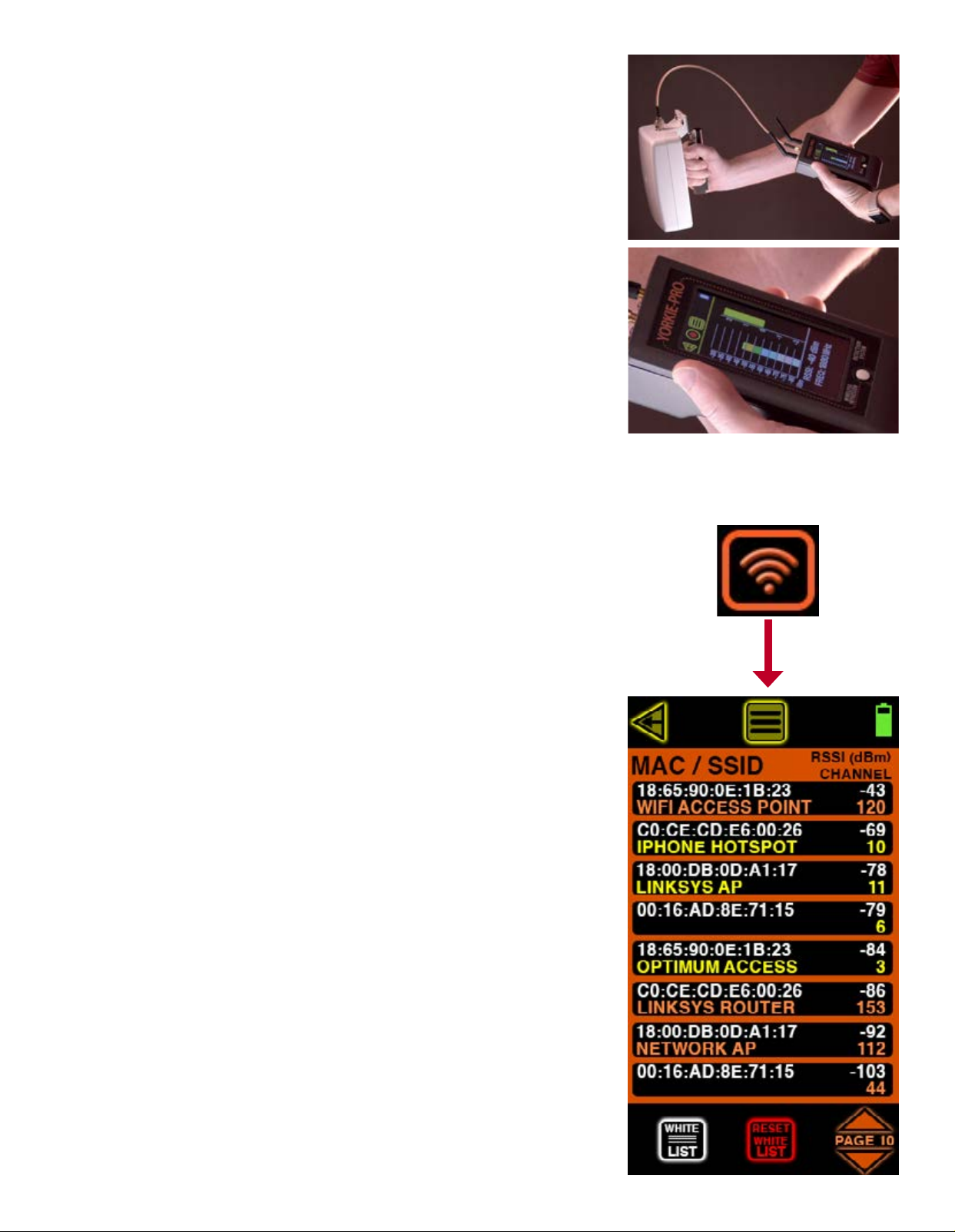
Starting from the MAIN MEASUREMENT screen, touch the Wi-Fi icon located on the bottom to scan
all nearby Wi-Fi access points. This screen indicates MAC address, RSSI signal strength in dBm,
802.11 channel number and SSID of every 2.4 GHz and 5 GHz access point detected. Orange
colored SSIDs indicate 2.4 Ghz and yellow SSIDs indicate 5 GHz. Yorkie-Pro will not detect any
client Wi-Fi devices.
Depending upon the number of access points and their activity, you might see the list updating
very frequently or not frequently at all. The strongest Wi-Fi access point will move to the top of
the list followed by the next strongest one and so on, but if you nd the list too long or changing
too frequently you can adjust the RF SCAN PERSISTENCE in the MAIN MENU settings. RF SCAN
PERSISTENCE does not affect measurements, it only affects how long measurements remain on
the screen after a signal is lost. The choices include ALWAYS ON, ALWAYS OFF, 10 SECS and 10
MINS. You might need to experiment with these settings depending upon your environment but
BVS recommends 10 SECS for most busy RF environments and 10 MINS for less busy RF environments.
WI-FI MEASUREMENT screen includes sorting and navigation buttons on the bottom. Touch the up
or down PAGE arrows in the lower right of the screen to navigate through the pages of APs and
their respective measurements
The WHITE LIST button allows users to remove known access points from the list. This feature
allows users to spend more time identifying unknown and possibly dangerous rogue APs instead
of continually sorting through access points that have already been scanned and accounted for.
Simply touch this button to activate this feature (the button will invert to indicate activation).
Next, touch each listed Wi-Fi device that you wish to white list. Every AP you choose will disappear from the list and not return until the unit power is reset or until you choose to reset yuor
white list. Touch the WHITE LIST button again when you are nished whitelisting access points.
RESET WHITE LIST button simply resets the white list of removed access points. Touch this button
to reset the list.
Page 7
Page 9
WI-FI DIRECTION FINDING
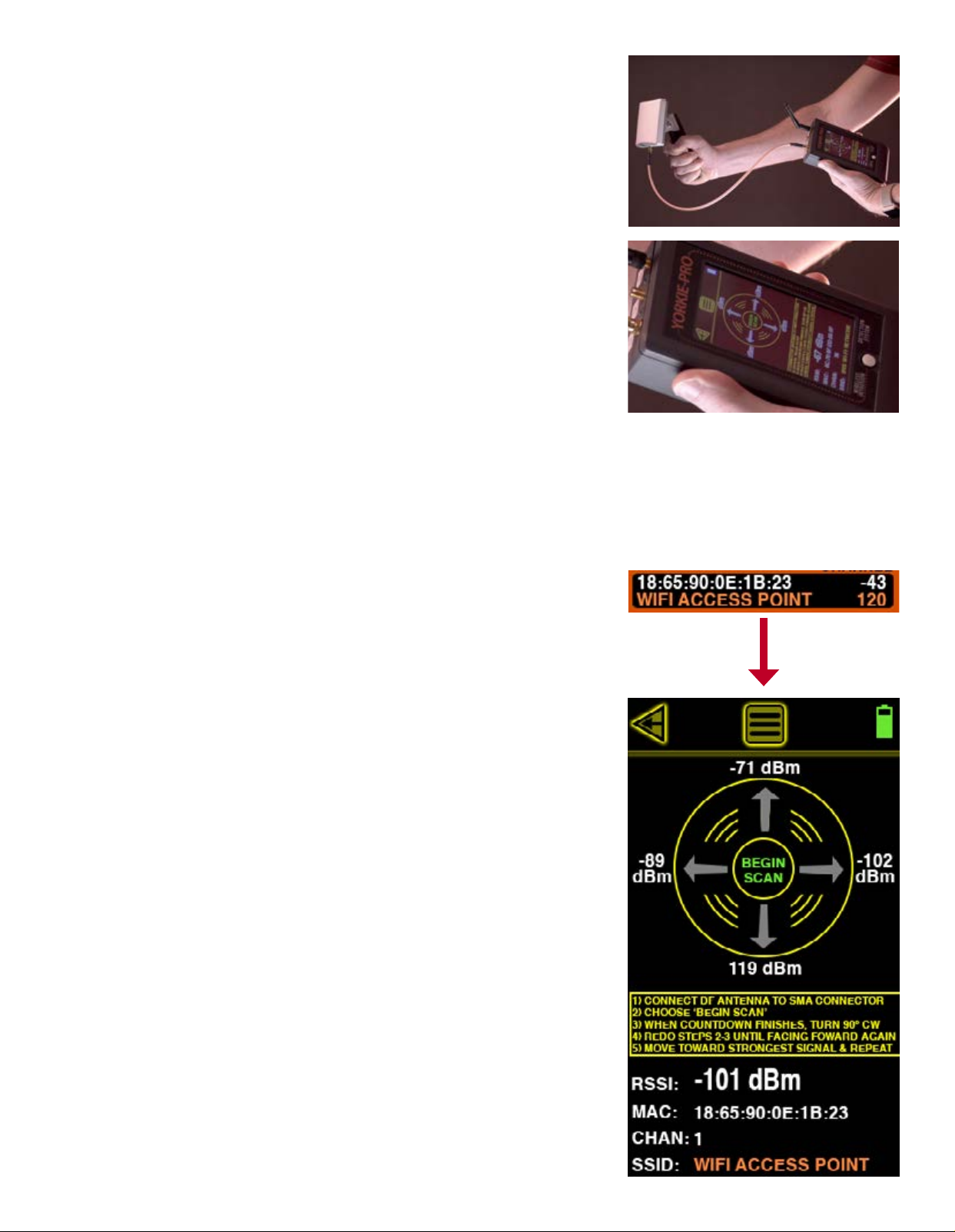
Once you have identied a Wi-Fi access point of interest, you can begin to locate it by choosing it
from the Wi-Fi MEASUREMENT list screen. That takes you to the WI-FI DIRECTION FINDING screen
seen here. This screen scans only the AP selected from the previous screen and delivers real time
and recently saved measurements allowing users to determine directionality of the AP scanned.
If you require a full Wi-Fi scan of all channels or Wi-Fi RF energy prole, use the BACK ARROW to
return to the MAIN MEASUREMENT screen.
In addition to Wi-Fi RSSI measurements in dBm, the WI-FI DIRECTION FINDING screen also displays the MAC address, Wi-Fi channel number and SSID of the access point.
Replace the omni-directional antenna with the large, 2.4/5.8 GHz DF antenna by connecting to
the SMA connector on the left side atop the Yorkie-Pro unit. BEGIN SCAN will continue to blink
until you touch it. The Yorkie-Pro will now begin scanning. Point the direction nding antenna
away from the unit and yourself and keep it parallel to the ground. After a few seconds of scanning, a number will appear atop the circle. Now you can turn 90 degrees and repeat the same
procedure until you are facing back in the original direction you started scanning.
Now that you have 4 different measurements (one for each direction) showing, you can determine the general direction of the access point you are trying to locate. For instance, the screen
shown here to the right indicates that the access point is most likely located between the two
highest measurements (between -89 dBm and -71 dBm) which means your new heading would
be somewhere between 10 and 11 o’clock or northwest (assuming you began your rst measurement facing north). RF reections and Wi-Fi network interference can sometimes change results
mid-scan so you can choose to repeat all of the same steps again to doublecheck your results or
you can move in the direction that this screen has indicated. It is recommended that you do not
walk much further than 25-50 feet at rst because once you get close to the access point, the
measurements tend to look similar to one another due to the overall sensitivity of the direction
nding antenna. Effective direction nding is best accomplished through patience and small
incremental steps. You might consider practicing on known access points before attempting to
locate an unknown AP.
Page 8
Page 10
BLUETOOTH MEASUREMENTS
Starting from the MAIN MEASUREMENT screen, touch the Wi-Fi icon located on the bottom to scan
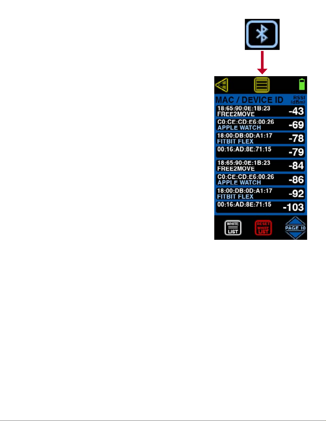
all nearby Bluetooth and BLE (Bluetooth Low Energy) devices. This screen indicates MAC address,
RSSI signal strength in dBm and device ID of every BT and BLE device detected. White colored
device IDs (friendly names) indicate BT and light blue colored device IDs (friendly names) indicate BLE devices.
Depending upon the number of devices and their activity, you might see the list updating very
frequently or not frequently at all. The strongest BT or BLE device will move to the top of the
list followed by the next strongest one and so on, but if you nd the list too long or changing
too frequently you can adjust the RF SCAN PERSISTENCE in the MAIN MENU settings. RF SCAN
PERSISTENCE does not affect measurements, it only affects how long measurements remain on
the screen after a signal is lost. The choices include ALWAYS ON, ALWAYS OFF, 10 SECS and 10
MINS. You might need to experiment with these settings depending upon your environment but
BVS recommends 10 SECS for most busy RF environments and 10 MINS for less busy RF environments.
BLUETOOTH MEASUREMENTS screen includes sorting and navigation buttons on the bottom.
Touch the up or down PAGE arrows in the lower right of the screen to navigate through the pages
of devices and their respective measurements.
The WHITE LIST button allows users to remove known devices from the list. This feature allows
users to spend more time identifying unknown and possibly dangerous rogue BT or BLE devices
instead of continually sorting through devices that have already been scanned and accounted
for. Simply touch this button to activate this feature (the button will invert to indicate activation).
Next, touch each listed Wi-Fi device that you wish to white list. Every AP you choose will disappear from the list and not return until the unit power is reset or until you choose to reset your
white list. Touch the WHITE LIST button again when you are nished whitelisting devices.
RESET WHITE LIST button simply resets the white list of removed BT and BLE devices. Touch this
button to reset the list.
Page 9
Page 11
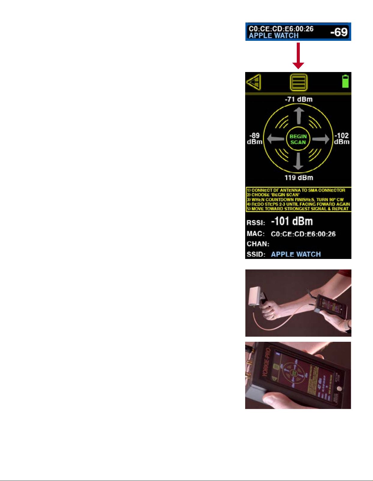
BLUETOOTH DIRECTION FINDING
Once you have identied a BT or BLE device of interest, you can begin to locate it by choosing it
from the BLUETOOTH MEASUREMENTS list screen. That takes you to the BLUETOOTH DIRECTION
FINDING screen seen here. This screen scans only the device selected from the previous screen
and delivers real time and recently saved measurements allowing users to determine directionality of the scanned device.
In addition to BT or BLE RSSI measurements in dBm, the BLUETOOTH DIRECTION FINDING screen
also displays the MAC address and device ID.
Replace the omni-directional antenna with the large, 2.4/5.8 GHz DF antenna by connecting to
the SMA connector on the left side atop the Yorkie-Pro unit. BEGIN SCAN will continue to blink
until you touch it. The Yorkie-Pro will now begin scanning. Point the direction nding antenna
away from the unit and yourself and keep it parallel to the ground. After a few seconds of scanning, a number will appear atop the circle. Now you can turn 90 degrees and repeat the same
procedure until you are facing back in the original direction you started scanning.
Now that you have 4 different measurements (one for each direction) showing, you can determine the general direction of the device you are trying to locate. For instance, the screen shown
here to the right indicates that the device is most likely located between the two highest measurements (between -89 dBm and -71 dBm) which means your new heading would be somewhere
between 10 and 11 o’clock or northwest (assuming you began your rst measurement facing
north). RF reections and BT or BLE device interference can sometimes change results mid-scan
so you can choose to repeat all of the same steps again to doublecheck your results or you can
move in the direction that this screen has indicated. It is recommended that you do not walk
much further than 25-50 feet at rst because once you get close to the device, the measurements
tend to look similar to one another due to the overall sensitivity of the direction nding antenna.
Effective direction nding is best accomplished through patience and small incremental steps.
You might consider practicing on known devices before attempting to locate an unknown BT or
BLE device.
Page 10
Page 12
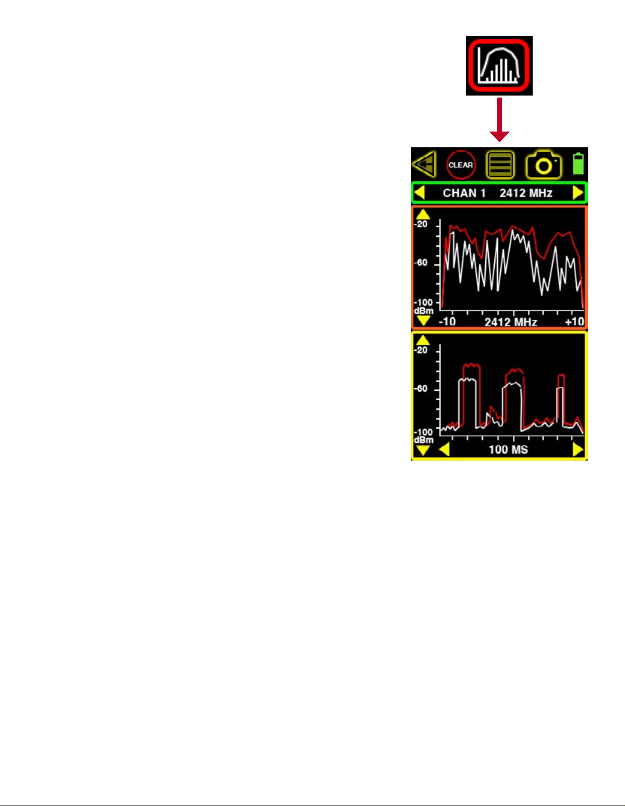
FREQUENCY ANALYSIS
The FREQUENCY ANALYSIS screen can only be accessed from the MAIN MEASURMENT screen. It
consists of 2 different panels that both scan the 2.4 GHz spectrum but do not display live data
simultaneously. The orange panel on top is a frequency domain that scans 20 MHz chunks starting at the center of each of the (14) 802.11b/g channels. The yellow panel on the bottom is a
time domain that samples a single frequency (same as center frequency in the top panel) over
a selectable time interval.
Touch the top panel to begin scanning by frequency. If the time domain panel below was active,
it will freeze during the frequency domain scan. Move along the spectrum in 20 MHz chunks by
touching the left or right yellow arrows on the green top panel. Adjust the dBm scale by touching
the up and down yellow arrows on the left side of the orange top panel just below.
Touch the bottom yellow panel to activate the time domain scan. If the frequency domain panel
above was active, it will freeze during the time domain scan. Move along the spectrum in 20
MHz chunks by touching the left or right yellow arrows on the green top panel. Adjust the dBm
scale by touching the up and down yellow arrows on the left side of the yellow bottom panel.
Choose between 100 ms, 1 sec and 10 sec using the yellow left and right arrows at the bottom
of this yellow panel.
The white lines indicate realtime activity in each panel and the red lines indicate peak activity
in each panel. Touch the CLEAR button at any time on the top to reset the red peak activity lines.
Each graph has its merits but the biggest value to most users is in capturing both domains’
signals and analyzing them together in order to recognize the combined pattern belonging to a
specic signal source.
Page 11
Page 13
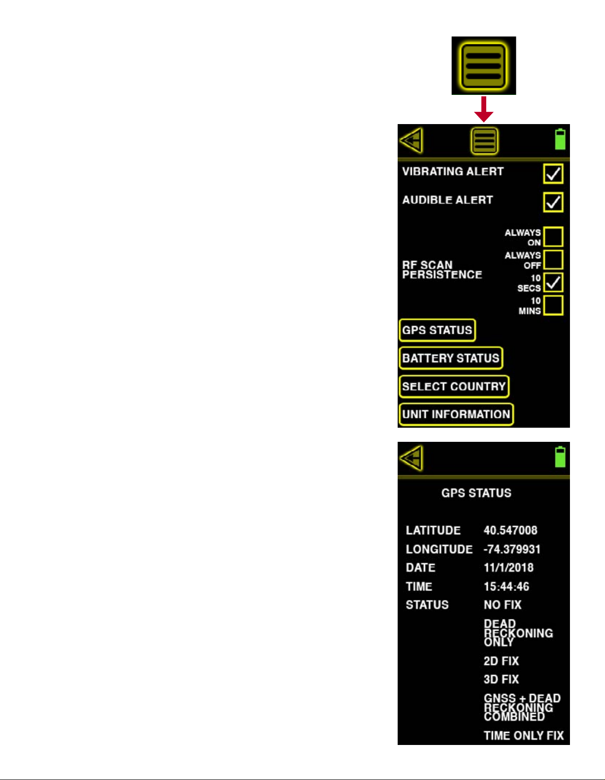
MAIN MENU
The MAIN MENU allows access to more of the Yorkie-Pro’s settings and information. These include
alerts, RF scan persistence, GPS, battery status, country selection and unit information.
VIBRATING ALERT
Touch the VIBRATING ALERT checkbox to toggle vibrating alerts on or off. When vibrating alerts
are turned on, the unit will vibrate everytime a set threshold is surpassed.
AUDIBLE ALERT
Touch the AUDIBLE ALERT checkbox to toggle audible alerts on or off. The unit will beep everytime a threshold is surpassed or any button is touched.
RF SCAN PERSISTENCE
RF SCAN PERSISTENCE only affects the rate at which Wi-Fi, BT or BLE measurements are displayed. For instance, only the last scan result will be shown when it is set to ALWAYS OFF. The
choices include ALWAYS ON, ALWAYS OFF, 10 SECS and 10 MINS. You might need to experiment
with these settings depending upon your environment but BVS recommends 10 SECS for most
busy RF environments and 10 MINS for less busy RF environments.
GPS STATUS
Touch the GPS STATUS button to display the Yorkie-Pro’s internal GPS receiver status including
latitude, longitude, date, time, x status, dead reckoning status, 2D x status, 3D x status,
GNSS + dead reckoning status and time x status. This information is useful primarily for users
performing site security surveys requiring export for reports and later analysis.
Page 12
Page 14
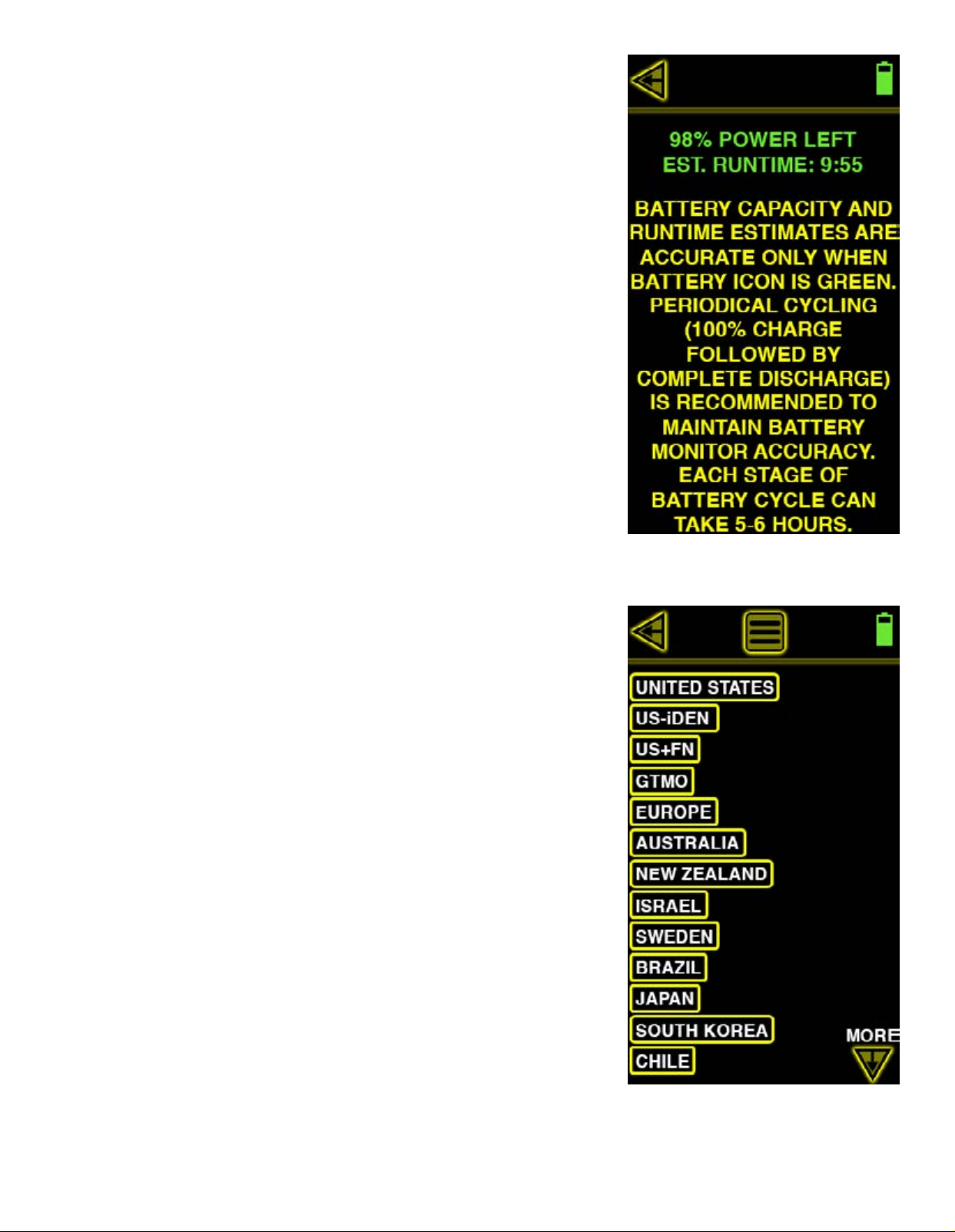
BATTERY STATUS
Touch the BATTERY STATUS button to see estimated remaining runtime down to the minute and
instructions for periodically cycling the battery to maintain superior battery life.
SELECT COUNTRY
Touch the SELECT COUNTRY button to match the country you are in when taking measurements
there. These countries only apply to the cellular measurements. The current selected country is
indicated by its two letter abbreviation near the top left of the MAIN MEASUREMENT screen. Supported countries or territories include: Unites States (US), Canada (CA), Europe (EU), Australia
(AU), New Zealand (NZ), Israel (IL), Sweden (SW), Brazil (BR), Japan (JP), South Korea (KR),
Chile (CL), India (IN) and Philippines (PH). Yorkie-Pro ships direct from the factory with support
for the country designated by the customer. Check with your BVS sales or support contact for
more details about support in your country.
Page 13
Page 15
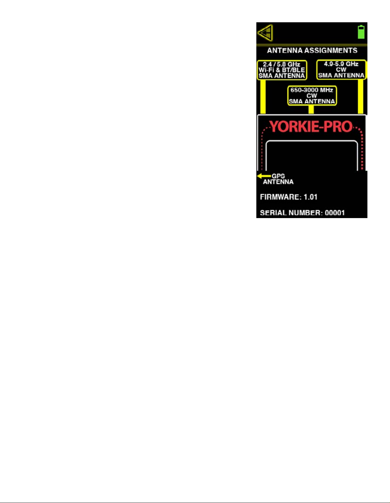
UNIT INFORMATION
Touch the UNIT INFORMATION button to access this screen for antenna assignments, rmware
and your unit’s serial number. Be sure to reference these SMA connection assignments when
attaching any antennas to your unit. Also be sure to reference this screen for the rmware and
serial number for any sales or support related issues.
Page 14
Page 16
Page 15
Page 17
Page 16
Page 18
Page 17
Page 19
Page 18
Page 20
Page 19
Page 21
Page 20
Page 22
Page 21
Page 23
Page 22
Page 24
Page 23
Page 25
Page 24
Page 26
Page 25
Page 27
Page 26
 Loading...