

Page 1

2390 Blackhawk Road • P.O. Box 6007 • Rockford, IL 61125 • www.nitesystem.com • 1-866-204-8570
Cascadia Under Bunk Mounting
Install Manual
Page 2

NITE Plus Installation Procedures
1-2
Freightliner Cascadia rev 10/7/2013
Table of Contents
Introduction
Before You Start
Parts List
Tools Reqquired
Installation Procedures
Electrical Installation
Espar Heater
1-3
1-4
1-5
1-7
1-8
2-1
3-1
4-1
5-1
Checklists
Webasto Heater
Page 3

NITE Plus Installation Procedures
1-3
Freightliner Cascadia rev 10/7/2013
Congratulations. You have chosen the
premier no-idle climate control system on the
market today—the NITE Plus system from
Bergstrom.
The NITE Plus is a powerful 12V
rechargeable DC system that keeps sleeper
compartment cool in hot weather and warm in
cold weather (with optional heater) without
having to idle the truck’s engine—and without
a genset. It not only dramatically reduces fuel
burned, it’s also very environmentally friendly.
Your NITE Plus is a self-contained,
hermetically sealed, compact A/C system
that produces approximately 4,600 Btuh and
has been quality engineered for years of
reliable service. The system operates
independently from your truck’s engine
using its own deep cycle batteries that are
completely separated from the truck’s
starting batteries.
The deep cycle batteries used are the most
advanced ever—and will efficiently power
the system for 8 to 10 hours. The batteries
are then fully recharged after just 4 to 6
hours of driving.
Add it all up, and you have a revolutionary
no-idle system that will save you money and
fuel year after year—the NITE Plus from
Bergstrom.
NOTE:
The NITE Plus A/C system is designed to
maintain a comfortable temperature inside the
sleeper without running the engine.
For optimal comfort, the curtain between the
cab and the sleeper must be closed when using
the unit. To enhance cooling efficiency during
the day, solar reflectors or curtains should be
placed over windshield and all windows to
block sunlight from entering the cab and
sleeper.
The NITE Plus A/C unit will not pull down a
hot sleeper that has been sitting in the sun
without the factory A/C running. To assist the
NITE Plus unit in cooling down the sleeper,
start the engine and run the factory A/C until
desired temperature is reached. The NITE
Plus unit will then maintain a comfortable
temperature depending on solar load &
ambient temperature.
Introduction
Page 4
NITE Plus Installation Procedures
1-4
Freightliner Cascadia rev 10/7/2013
Before You Start
A typical installation of the NITE Plus generally takes
between 8 to 10 hours, although your particular
situation may vary. This manual contains step-by- step
installation instructions. It is divided into three
categories:
● General installation
● Electrical installation
● Heater installation (optional)
There is also a section on how to check your NITE Plus
to make sure the installation was successful, and a
section on how to operate your NITE Plus.
If relocation or reinstallation of any pre-installed
equipment is necessary for installation of the NITE Plus
equipment - please refer to the components manufacturer's
instructions or safety guidelines for proper installation.
Before you start, we highly recommend doing the
following to help make your installation as easy as
possible.
1. Lay out all parts and check to make sure you have
all parts listed on the parts list.
Depending on truck, some hardware may not
be used. If you are missing any parts, please call
1-866-204-8570.
2. To prevent damage to compressor, keep the NITE
Plus unit in an upright position at all times. If unit
is tipped, place back in upright position for a
minimum of 6 hours prior to running.
3. Check the list of tools needed for installation and
make sure you have all of them. Keep all tools
within easy reach.
4. Look through the whole installation manual to get
an understanding of the order in which
components are installed.
5. Make sure you have good lighting and enough
space to work in.
6. You may want to get an assistant to help you to
reduce the number of times you have to climb in
and out of the cab.
7. Make sure you wear all appropriate safety
equipment.
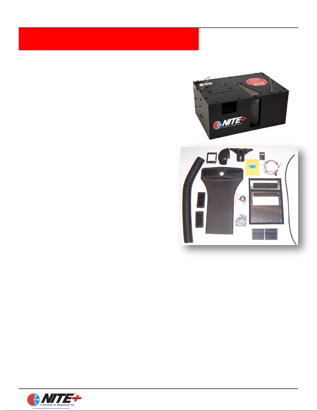
Photo above is representative of kit
1000113986 only.
Page 5
NITE Plus Installation Procedures
1-5
Freightliner Cascadia rev 10/7/2013
Bergstrom
Part #
Part Description
Quantity
1000113877 NITE STANDARD KIT A/C ONLY
1000078163
ASSEMBLY, NITE UPGRADE UNIT
1
1000014440
KIT, NITE POWER
1
1000007552
POLICY, NITE WARRANTY
1
585421
MANUAL, NITE OPERATION
1
585511
CARD, NITE, WARRANTY SURVEY
1
1000119244 NITE STANDARD KIT A/C & HEAT
1000078163
ASSEMBLY, NITE UPGRADE UNIT
1
530713
KIT, ESPAR HEATER
1
1000014440
KIT, NITE POWER
1
1000007552
POLICY, NITE WARRANTY
1
585421
MANUAL, NITE OPERATION
1
585511
CARD, NITE, WARRANTY SURVEY
1
1000113986 INSTALL KIT
454651
ANGLE – DUCT COLLAR
1
500105
LOUVER, CARY 633 WITH 631 BEZEL
2
500198
GRILLE, AIR RETURN
1
560235
HOSE DEFROST 4.0 X 45”
1
584510
PLUG BUTTON .5 IN HLE 3L4566
2
870235
ASSY, MOUNT PLATE 4 BEND
1
1000007614
DUCT, UPPER
1
1000007617
DUCT, STEALTH
1
1000007618
DUCT, TRANSITION
1
1000011467
CONTROL DUCT ASSY
1
1000113415
WIRE HARNESS NO IDLE CONTROL
1
1000113881
TEMPLATE, NITE FLOOR
1
1000115617
CD ROM, NITE INSTALL MANUALS
1
1000113995
KIT, NITE STANDARD HARDWARE
1
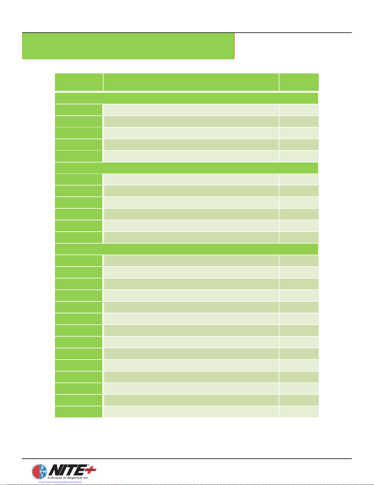
Parts List
Page 6
NITE Plus Installation Procedures
1-6
Freightliner Cascadia rev 10/7/2013
Bergstrom
Part #
Part Description
Quantity
B290303
CLAMP, HOSE 4.12 I.D.
2
B300571
EDGING BULK
4 FT
B360692
GROMMET, NO 6 AND NO 10 HOSE ADAPTER
2
1000014440 NITE Plus POWER KIT
660706
ASSY, WIRE BATTERY CABLE 5300MM BLACK
2
660707
ASSY, WIRE BATTERY CABLE 5000MM RED
3
660694
ASSY, WIRE BATTERY CABLE 225MM
2
660678
HARNESS, WIRE NO-IDLE POWER
1
660827
WIRE, 16 GAUGE BLACK
1
651383
SEPARATOR 200 AMPS
1
651225
FUSE, MAXI 50 AMP
1
B230083
RING TERMINAL, 5/16
2
B300642
WIRE LOOM, .413 I.D. X BULK – BLACK SPLIT
PLASTIC
70 ft.
B300652
WIRE LOOM, .625 I.D. X BULK – BLACK SPLIT
PLASTIC
15 ft.
B360113
STRAP, CABLE TIE
50
709860
BLADE TERMINAL
1
708000
RING TERMINAL, 5/16 16 GAUGE
1
651462
HEAT SHRINK TUBING
10
670136
5/16 RING TERMINAL, 4 GAUGE
8
670137
3/8 RING TERMINAL, 4 GAUGE
2
660706
ASSY, WIRE BATTERY CABLE 5300MM BLACK
2
660707
ASSY, WIRE BATTERY CABLE 5000MM RED
3
660694
ASSY, WIRE BATTERY CABLE 225MM
2
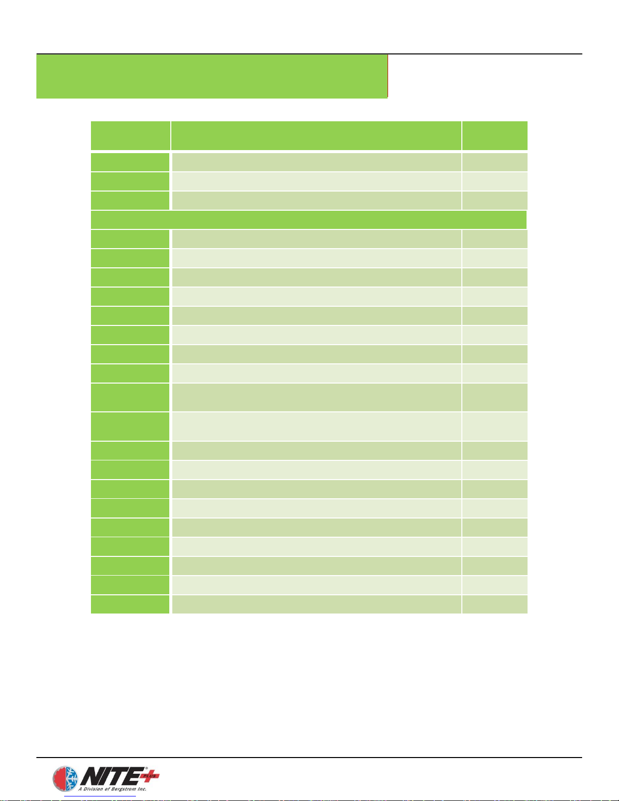
Parts List
Page 7

NITE Plus Installation Procedures
1-7
Freightliner Cascadia rev 10/7/2013
Tools Required
1) Drill Bit Set
2) Hole saws (1″, 1-5/8″, 2″, 2-1/2″ and 4-3/4″ )
3) Electric/Air Drill
4) Screwdrivers/Assorted Bits (Flat Head & Phillips Head)
5) Impact Gun
6) Air saw/Jigsaw (Cutting Sheet metal)
7) Torx Head (T30) Bit
8) Metric Wrenches
9) SAE Wrenches
10) 1/4″, 3/8″ Drive Ratchets
11) SAE Socket Set
12) Metric Socket Set
13) Wire Cutters
14) Terminal Crimpers
15) Wire Strippers
16) Razor Knife
17) Electrical Tape
18) Cable Cutters
19) #4 Professional Grade Cable Crimpers
20) Cable Strippers
21) Work Light
22) Torque Wrench up to 50 in/lbs
23) U-barrel Crimper
24) Pop Rivet Gun
Page 8
NITE Plus Installation Procedures
1-8
Freightliner Cascadia rev 10/7/2013
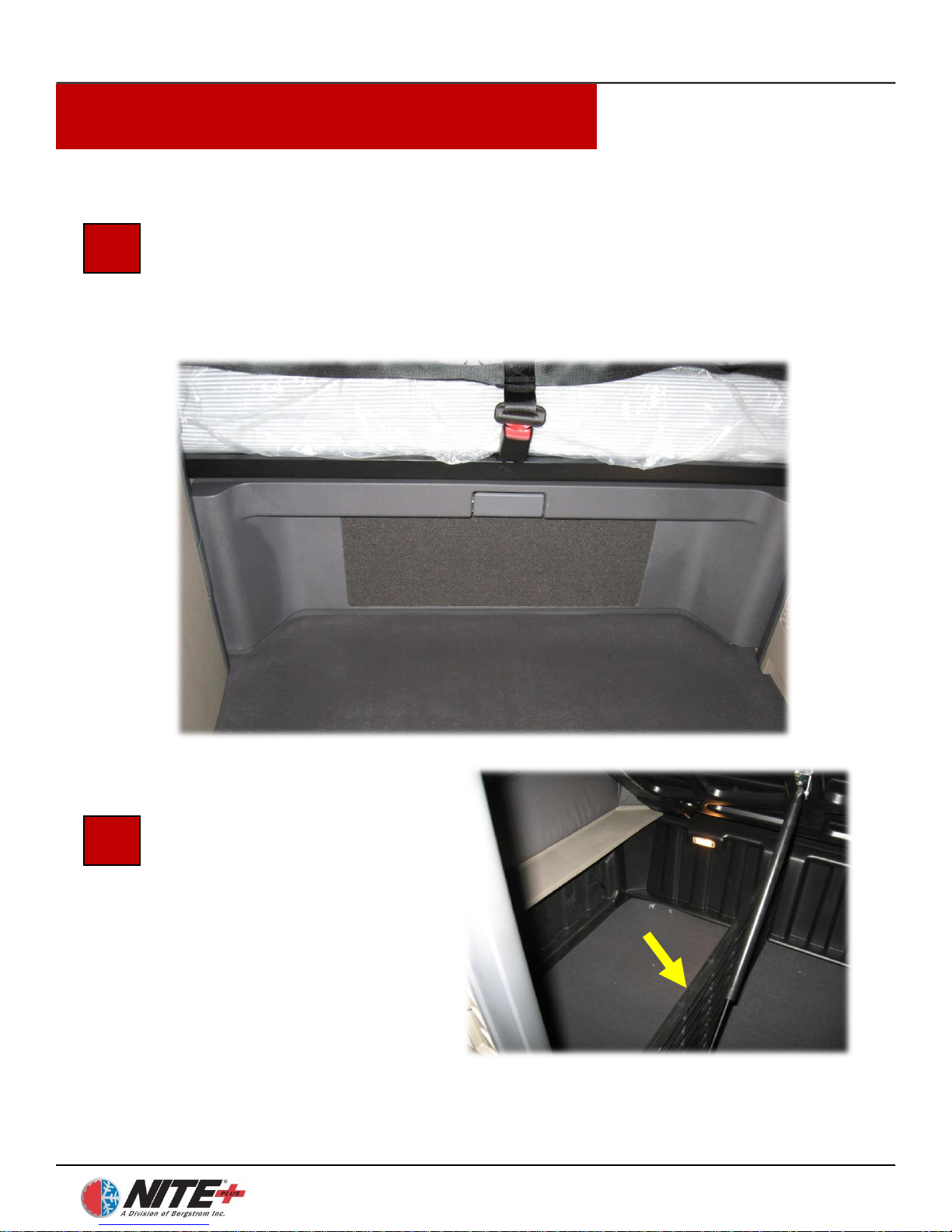
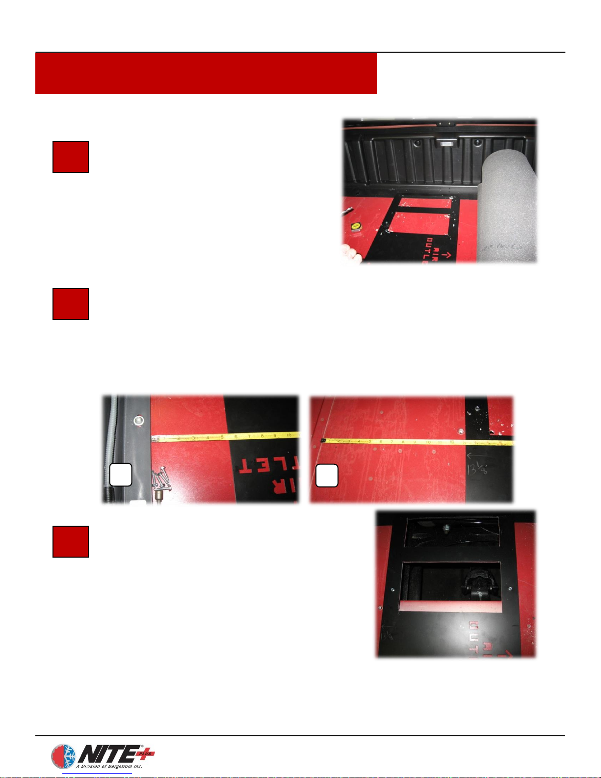
Prepare the Work Area
Set up your work light, clear the sleeper compartment of loose items, and
remove the divider curtain if there is one. Then remove the mattress and set
outside the cab. The NITE Plus unit is going to be mounted under the lower
bunk in the central compartment.
Remove Left Divider Wall
Remove the left divider wall by
removing the screws at each
end. Set wall outside the truck.
Removal of this divider wall
will allow you to roll up the
floor mat from left to right.
1
2
Page 9
NITE Plus Installation Procedures
1-9
Freightliner Cascadia rev 10/7/2013
Rollup Floor Mat
Rollup the floor mat from left to right.
You will now be able to see the floor
rivets which will help you determine the
location for the NITE Plus unit. Set the
NITE Plus floor template on the floor
of the center compartment.
Determine Location for NITE Plus unit Mounting Plate
Position the provided template 5 ¼ ″ from the front wall (A) and 13 ⅛″
from the left floor seam (B). Note the rivets in the floor – this indicates
where the flooring cross members are located. You can now mark the two
rectangular openings in the template. Check under the truck for any
obstructions before drilling or cutting.
3
4
5
Cut Out Floor Openings
Drill ½″ starter holes in opposing corners
of the two areas marked for cutting. Use air
saw/jigsaw to cut through truck floor.
These two openings will provide condenser
air inlet and exhaust for the NITE Plus
unit.
NOTE: Check under the truck for any
obstructions before drilling or cutting.
A
B
Page 10
NITE Plus Installation Procedures
1-10
Freightliner Cascadia rev 10/7/2013
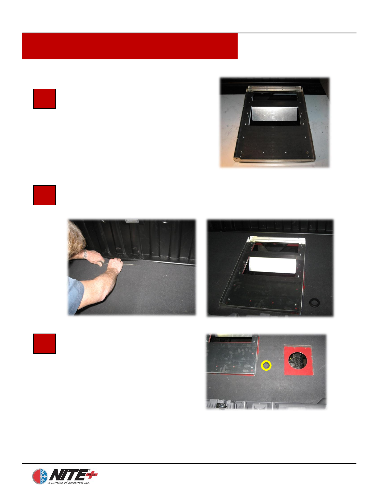
Install NITE Plus Mounting Plate
Remove the floor template and position
the NITE Plus mounting plate with the
pre-cut recirculation grills, over the holes
cut in the truck floor. The openings in the
plate should be towards the rear of the
truck. Attach to the floor through the
predrilled holes using self-tapping screws.
Trim Floor Mat Around the Mounting Plate
Roll the floor mat back over the mounting plate. Use a utility knife to trim
out the area around the mounting plate.
6
7
Drill Hole for Power
Harness Wiring
Drill a hole through the truck floor
(yellow circle) to run the power
harness. Insert grommet in hole prior
to running wires.
NOTE: Hole can be located any
location where there are no
obstructions under the truck.
8
Page 11
NITE Plus Installation Procedures
1-11
Freightliner Cascadia rev 10/7/2013
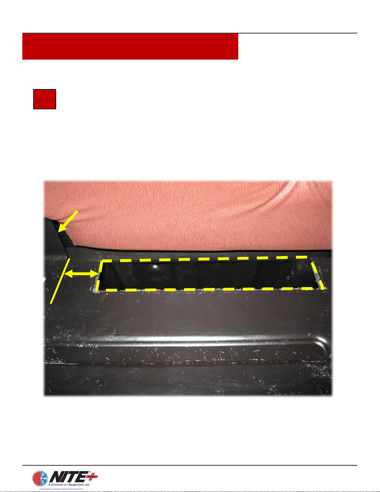
Cut Out Notch from Bunk Decking to Install NITE Plus Duct
Cut a notch in the back edge of the bunk decking to allow the NITE Plus
duct to run down through it. The notch should be 13 ¼ ″ wide by 2″ deep.
This notch should be located 2″ from the right edge of the center hinge.
9
2″
Center Hinge
Page 12
NITE Plus Installation Procedures
1-12
Freightliner Cascadia rev 10/7/2013
10
11
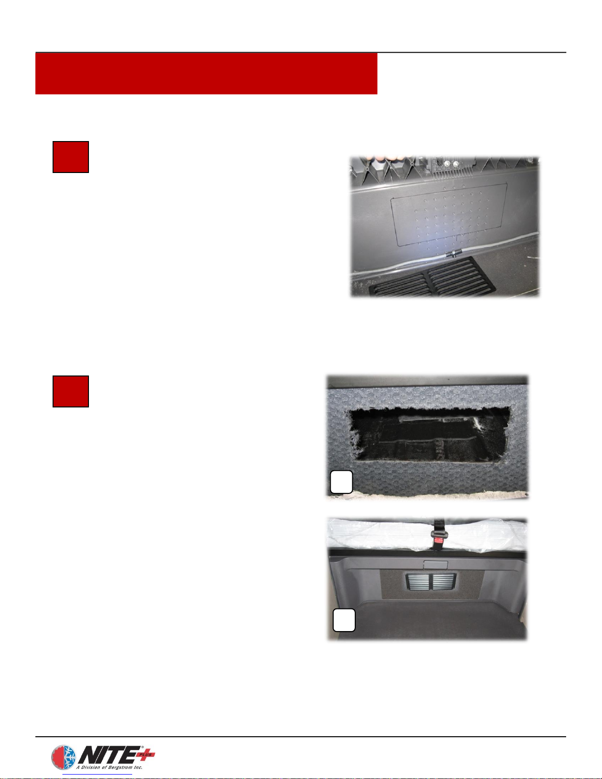
Determine Location for
Recirculation Grill
We recommend installing the grill in the
center support wall (see photo showing
outline for cutout marked on rear side of
support wall). The opening should be
positioned in front of where the NITE
Plus unit will be positioned. The size
should be 11 1/2″ x 4 5/8″.
Cut Opening for
Recirculation Grill
Cut an opening (A) with a metalcutting air saw or jigsaw for the
recirculation grill in the support wall.
Attach grill (B) to the center wall
using black Phillips head screws.
A
B
Page 13
NITE Plus Installation Procedures
1-13
Freightliner Cascadia rev 10/7/2013
13
14
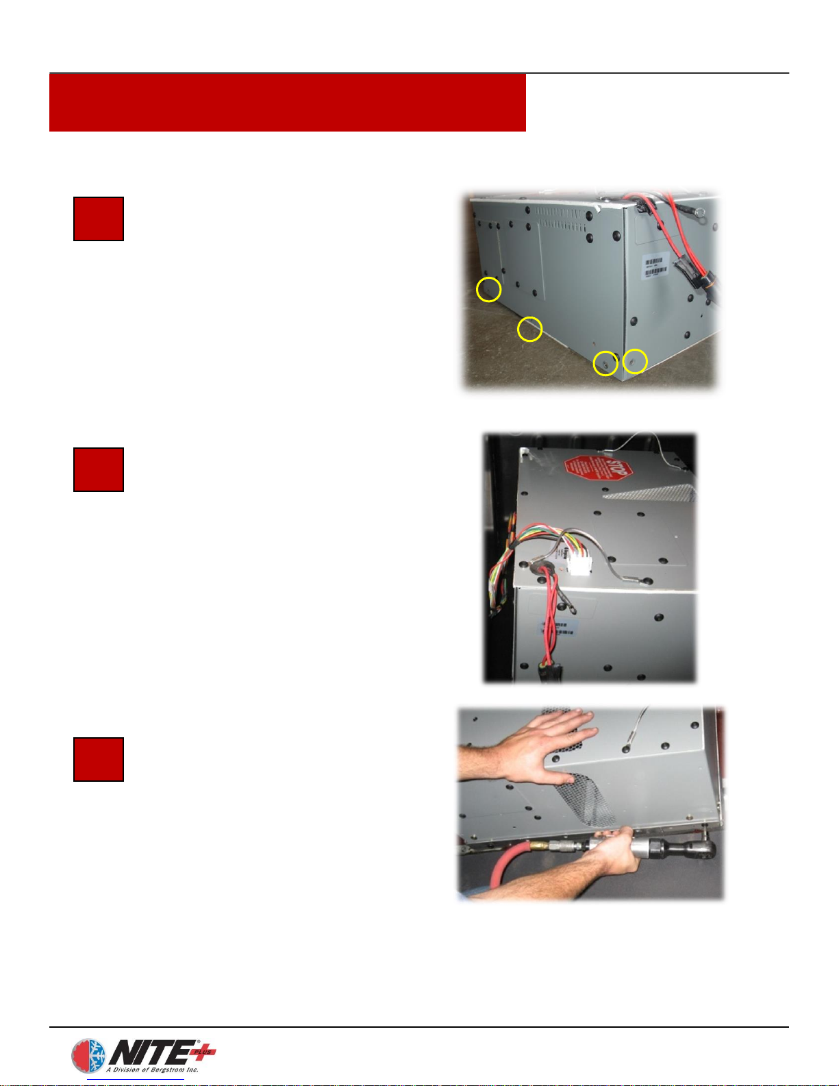
Prepare Unit for Install
Remove the three screws shown in the
illustration from the front bottom of
the NITE Plus unit, and one screw
from the right-side bottom corner. The
unit is now ready to be placed in the
truck.
Place Unit into Position
Carefully lift the NITE Plus unit by
the two strap handles and set it on top
of the aluminum mounting plate. Be
Careful to keep unit level at all times.
The “STOP” label should be towards
the rear of the truck facing the
passenger side as pictured. Be careful
not to catch or pull on the wiring
harness.
Attach Unit
Install screws through the lip on the
mounting plate into the NITE Plus
unit.
12
Page 14
NITE Plus Installation Procedures
1-14
Freightliner Cascadia rev 10/7/2013
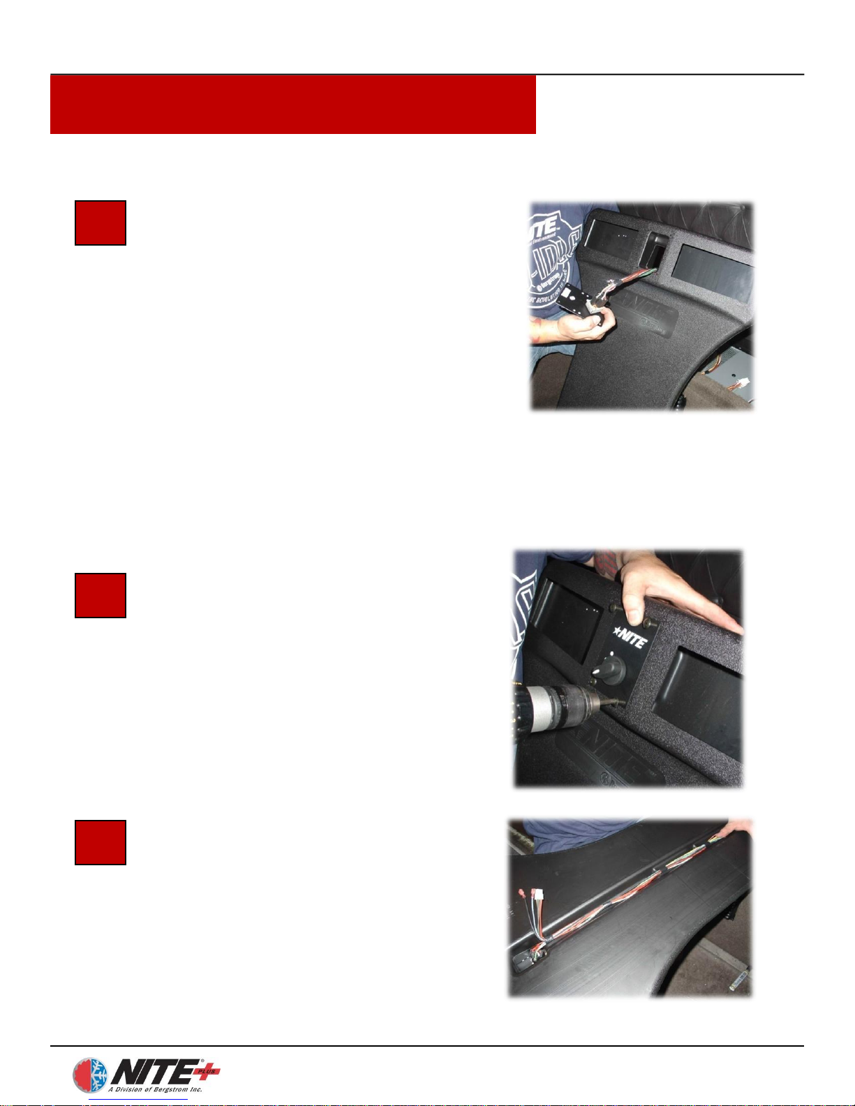
Feed Control Wiring
Through NITE Plus Duct
Take the NITE Plus duct and thread the end
of the wiring harness with the 5 prong black
plug through the opening from the backside
to front. Attach the control panel to the
wiring harness using the wires with a 5prong plug—make sure the connection is
tight and secure. (The other three wires are
not used in this particular installation.)
Attach Control Panel to NITE Duct
Push wiring behind duct, and mount the
control panel to the duct using ¾” black
Phillips head screws through the pre-drilled
holes. Tighten carefully. When finished
make sure switch is in the off position!
Run Wiring behind NITE Plus Duct
Place the wiring harness along the channel
on the back of the duct. The duct is now
ready to be attached.
15
16
17
NOTE: If you will be installing the optional ESPAR heater please
review step 17 of the heater control panel installation instructions
before proceeding.
Page 15
NITE Plus Installation Procedures
1-15
Freightliner Cascadia rev 10/7/2013
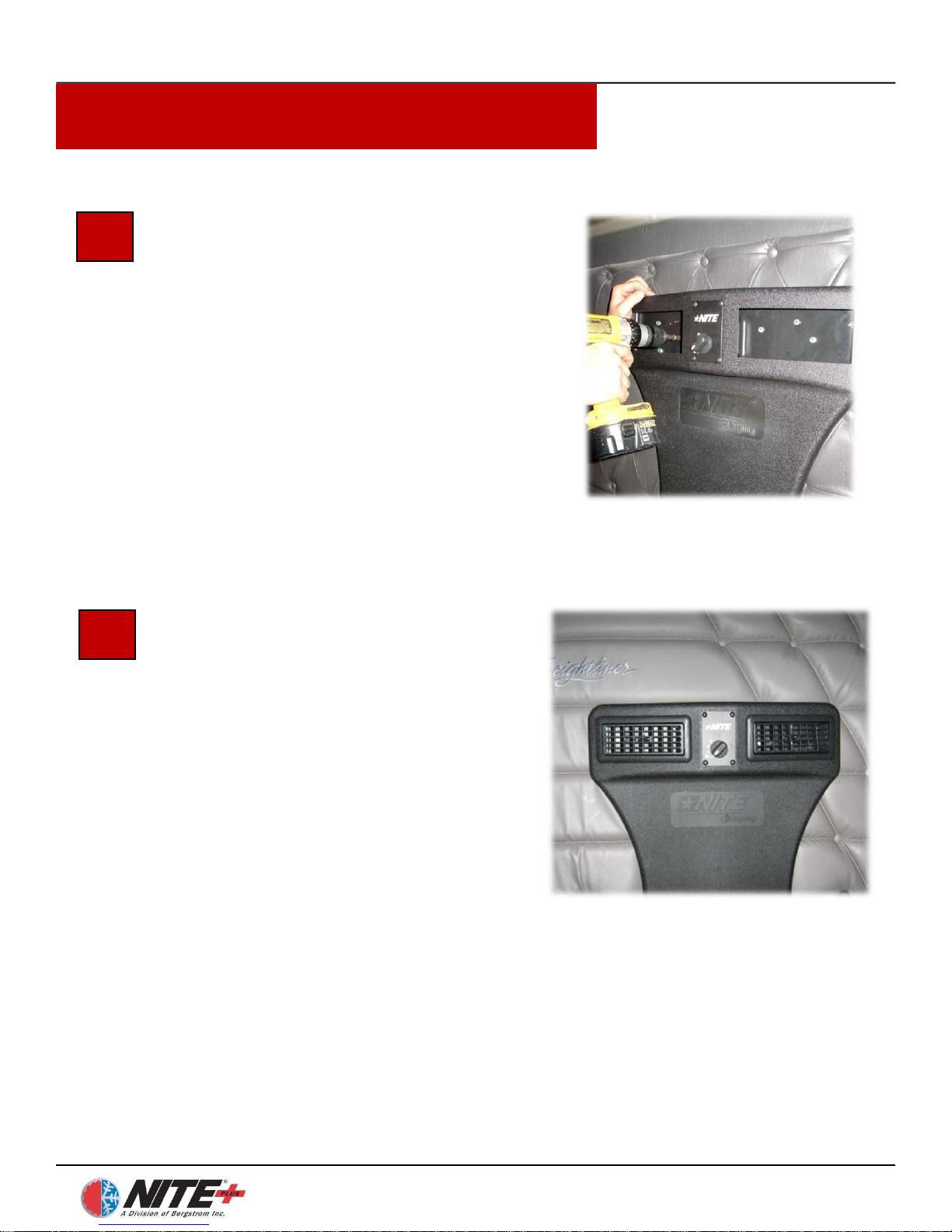
Attach Duct to Back Wall
Place the bottom of the duct down through
the opening you cut in the top of the bed
pan and press the top of the duct up
against the back wall. Make sure the duct
is square and level against the back wall
and that you leave space at the bottom for
the rest of the duct assembly. Use 1” 5/16
hex head self-tapping screws to attach top
of duct to back wall. Place 3 - 5 screws in
each duct opening and install at different
angles. Take care not to over tighten.
Attach Vents to NITE Plus Duct
Snap the louvered vents into each of the
duct openings—no screws are necessary.
19
18
Page 16
NITE Plus Installation Procedures
1-16
Freightliner Cascadia rev 10/7/2013
21
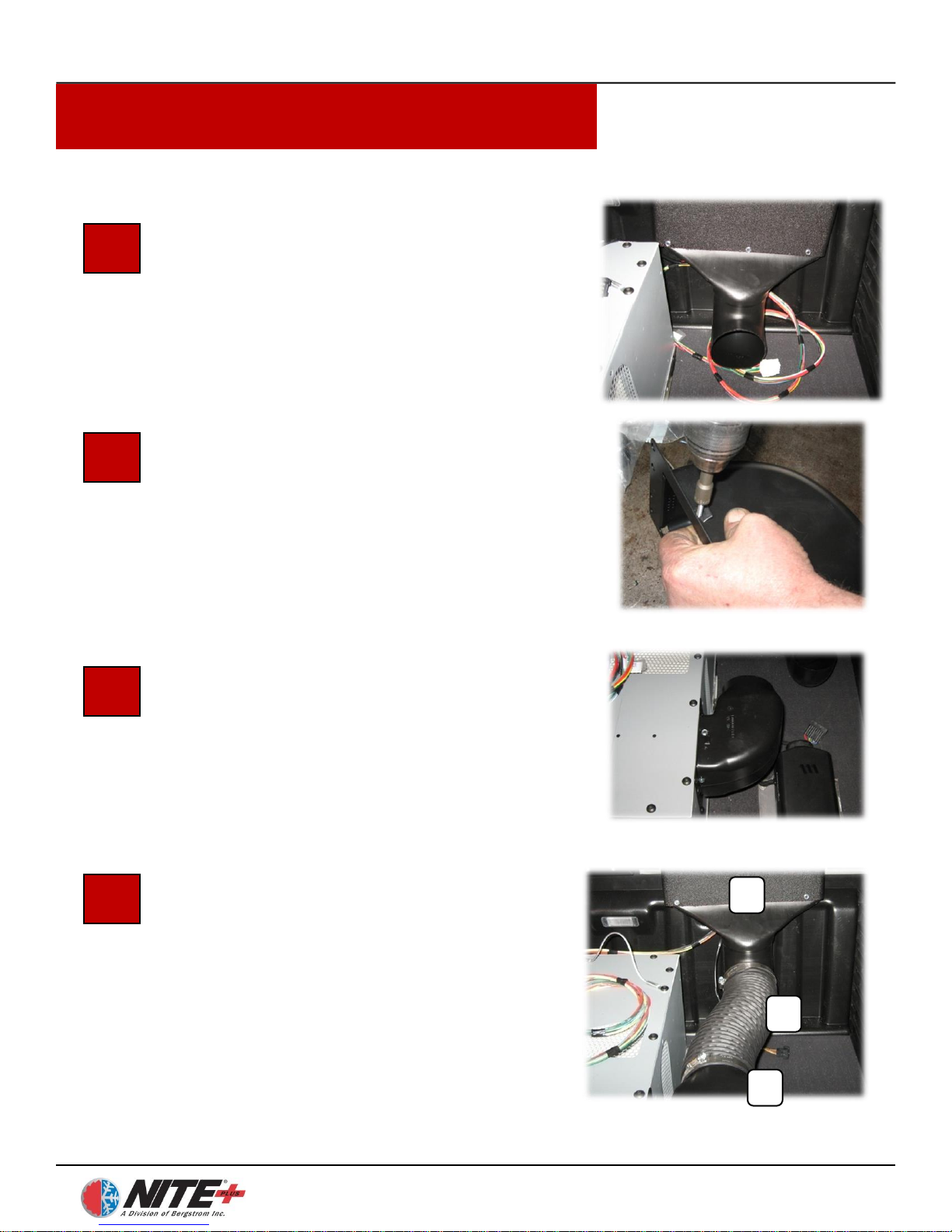
Attach Bottom of NITE Plus Duct
to Duct assembly
Attach the transition duct to the bottom of
the NITE Plus duct using two 1” 5/16 self-
tapping screws (circled).
Attach Metal Flange Adapter
to Elbow.
Attach with 3 hex head self-drilling
screws. Seal around flange with silicone
sealant (not included in kit).
Attach Assembled Elbow to Side of
NITE Plus Unit
Attach the elbow to the side of the NITE
Plus unit using #30 torque screws.
Attach Flexible Duct to Assembled
Elbow and Transition Duct
Insert flexible duct (A) onto the round end
of the elbow unit (B). Attach other end of
the flexible duct to the transition duct (C).
Tighten hose clamp to secure flex duct to
elbow and transition duct.
20
22
23
A
B
C
Page 17
NITE Plus Installation Procedures
1-17
Freightliner Cascadia rev 10/7/2013
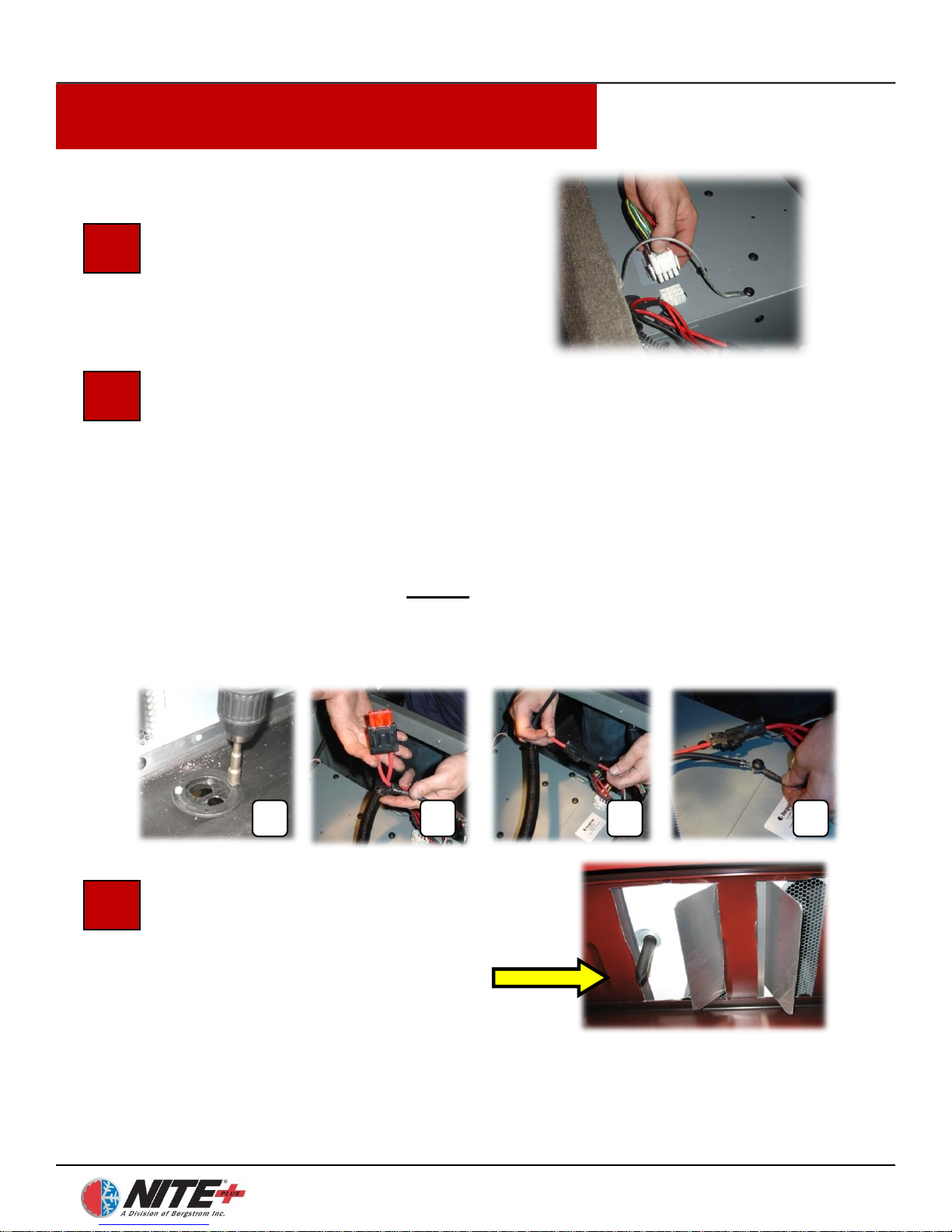
Attach Control Cable to Unit
Snap control cable harness, coming from
the NITE Plus duct, into plug on top of
NITE Plus unit – it only fits one way.
24
25
Install Drip Tube Under Truck
All drip tubes are the same but photo
may not represent actual application
26
BC D
Install the NITE Plus Unit Power Harness
Take the power harness and place the protective split plastic loom around
it. Install provided grommet into hole in the floor (A). Make sure to use
this grommet to protect cables as you run the cables from the NITE Plus
unit, down through the frame rails to the NITE Plus batteries. Secure with
zip ties. Insert a 50 amp MAX fuse in the fuse holder at the NITE Plus
unit end of the power harness (B). Plug the positive end into the positive
plug on the NITE Plus unit (C). Remove a screw from the NITE Plus
unit surface, place it through BOTH of the negative ring terminals and reattach to the NITE Plus unit (D).
NOTE: DO NOT USE THE SCREW HOLDING CARRYING STRAP FOR GROUNDING!
A
Page 18

®
NITE Plus
SECTION 2
ELECTRICAL
INSTALLATION
Page 19
Electrical Installation
2-1
2
NOTE: Bergstrom does not condone putting batteries under the sleeper bunk. The floor is not designed to
carry that amount of weight and even deep cycle AGM batteries can emit gas under certain
circumstances. Bergstrom can only support batteries being placed in battery boxes or tool boxes designed
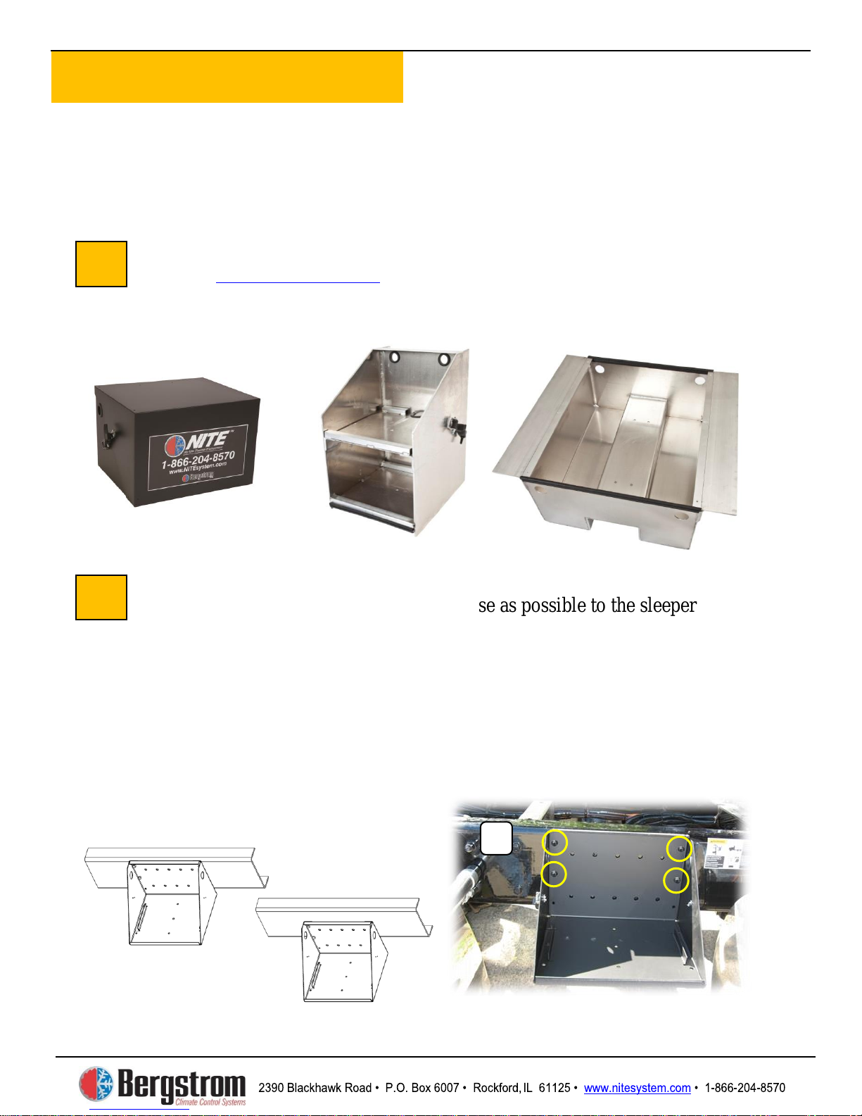
Steel Battery Box Installation
Locate the battery box on the frame as close as possible to the sleeper NITE
Phoenix unit. When positioning the box, always keep the top of the box as
close to the top of the frame rail as possible – Some manufacturers recommend
no drilling within 2″ of top or bottom of frame rail. Check truck manufacturer
guidelines prior to drilling.
of 4 holes. Always use the holes in the rear outer corner area where you have
double walled steel. Of the 3 holes available on each side of the outer most
edge of box, choose the top and center holes on each side (see photo A). Drill
frame rail using ½″ HS bit. Install box with ½″ grade 8 bolts and hardware
provided. Tighten securely
1
A
Correct
Incorrect
Available Battery Boxes Options
Refer to
for styles and part numbers. Aluminum clamp-on
boxes include between rail and vertical box styles. Steel battery boxes require
frame drilling and must be attached to frame rail with bolts (see instructions in the
following steps 2 and 3).
Vertical
Between Rail
Steel Battery Box
to support the weight of the batteries outside the cab of the truck.
www.nitesystem.com
(2 required)
Clamp-On Box
Using box as template, mark and drill a minimum
.
Clamp-On Box
Page 20
Electrical Installation
2-2
Attaching Hold-down Brackets
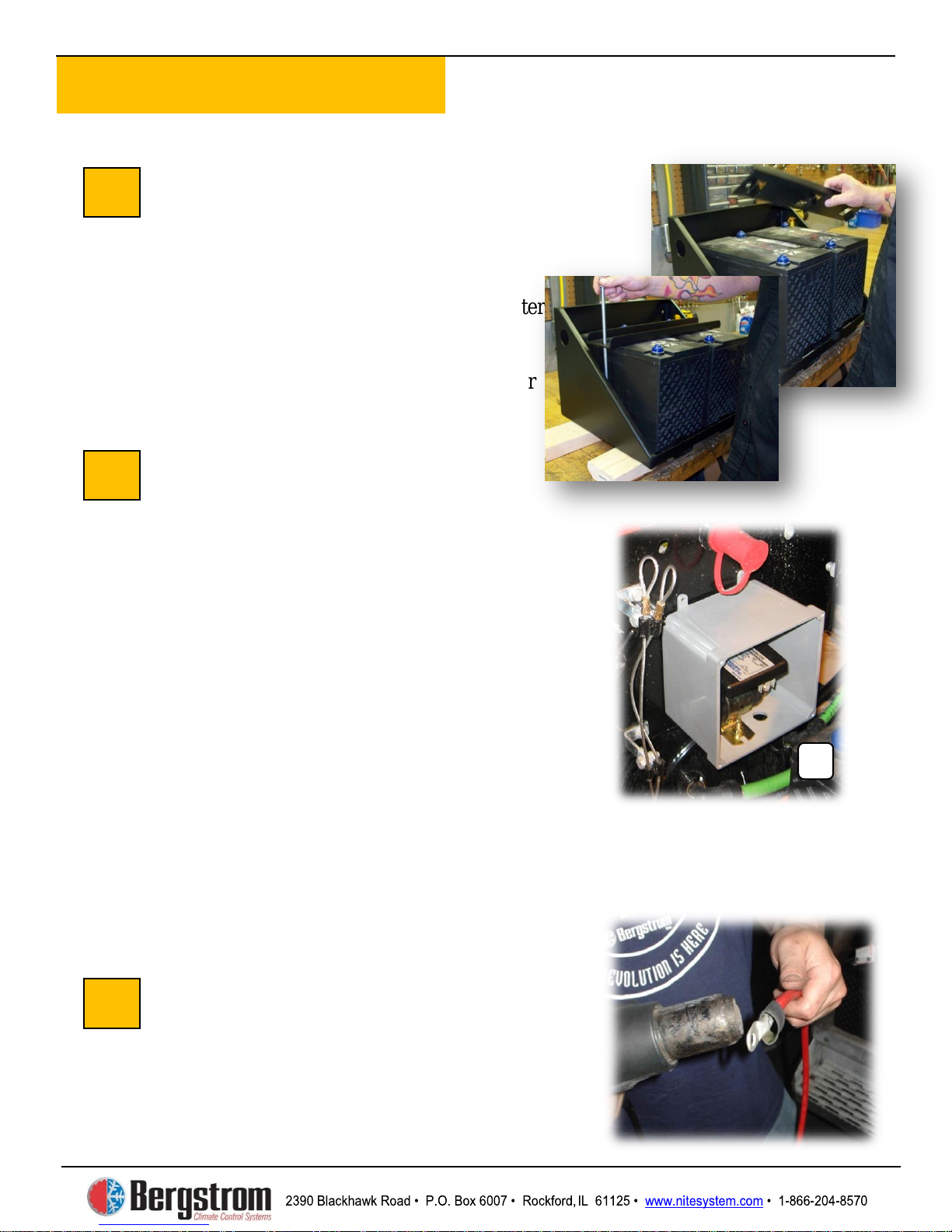
Set two batteries side-by-side in the battery
box and place a hold-down bracket on top,
with the u-channel facing up. Take two
5/16″ bolts, place a 5/16″ flat washer on
each, and then put the bolts through the outer
holes. Tighten each bolt securely from
underneath using the supplied nuts and
washers. Repeat the procedure for the other
two batteries.
Mounting the Separator
Mount separator in battery compartment or
in supplied 6 x 6 x 4 enclosure.
Mount enclosure first
3/8″ holes in the back of the box, to use for
mounting. Secure with 3/8″ bolts/ washers/
lock nuts. DO NOT USE THE OUTSIDE
TABS FOR MOUNTING THE BOX!!
Mount separator inside enclosure.
and drill two ¼″ holes in bottom side to
mount the separator, attach with ¼″ bolts /
washers / lock nuts. You must also drill two
½″ holes directly under the posts of the
separator where the cables will connect.
NOTE
starting batteries and gives priority to the
starting batteries. It then charges the
NITE aux batteries. The aux batteries
begin charging after the starting batteries
reach 13.2V
Preparing Cables
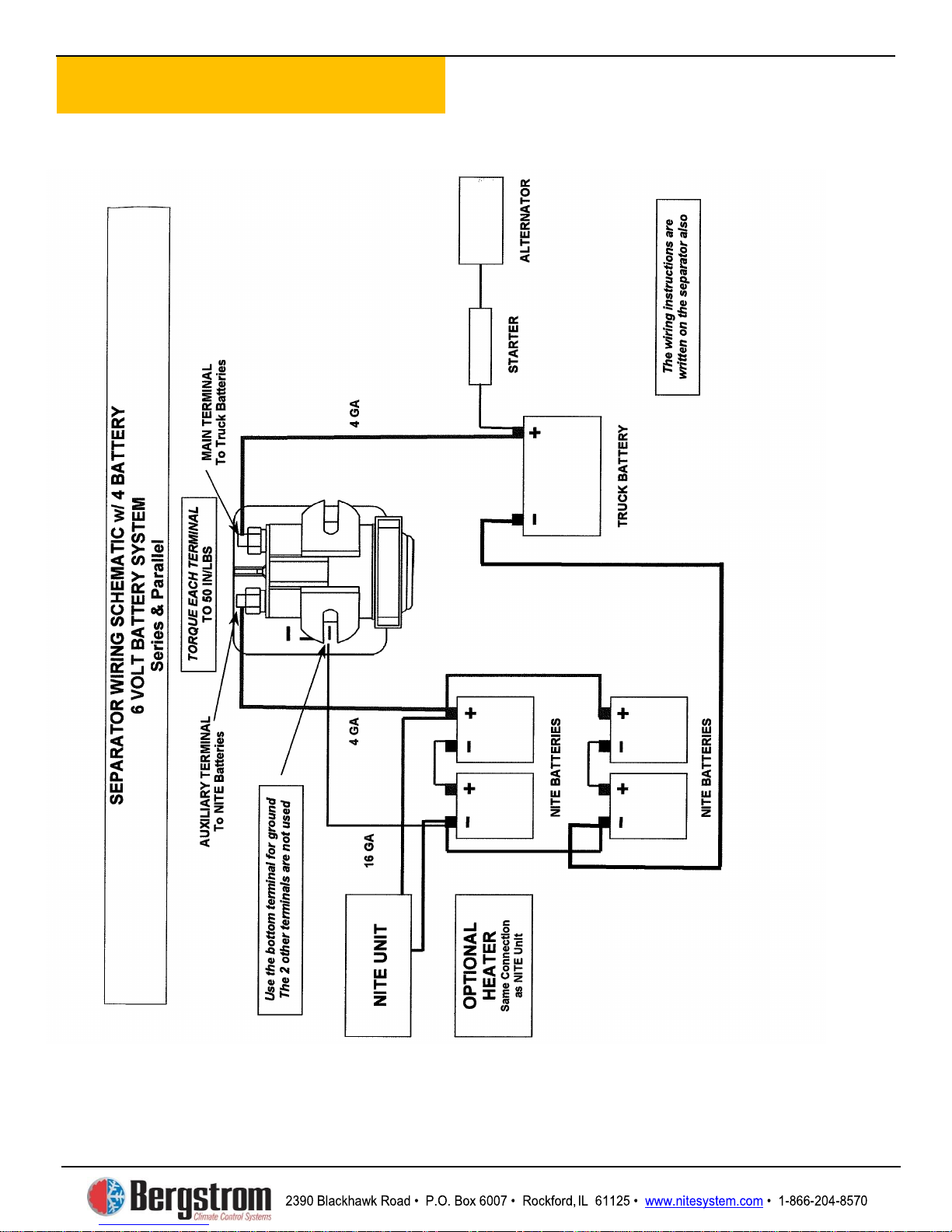
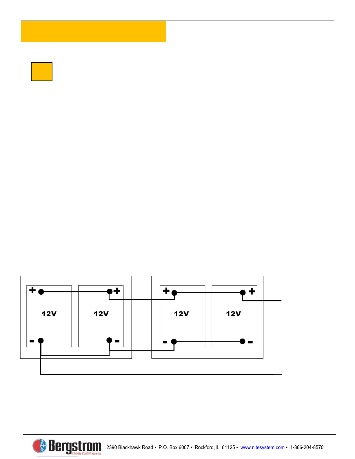
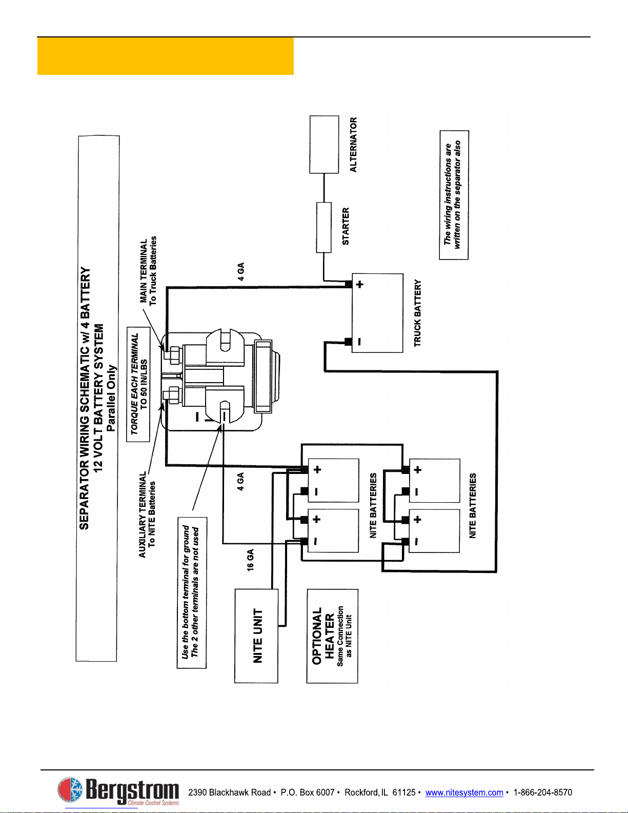
The batteries are wired series/parallel for 6V
or parallel only for 12V. See diagrams on
pages 2-3 to 2-6.
3
5
4
A
: The separator ties into the truck’s
.
. Mark and drill two
Mark
NOTE: Before proceeding – Make sure the NITE
PLUS control switch is turned off. Disconnect the
truck batteries.
Page 21
Electrical Installation
2-3
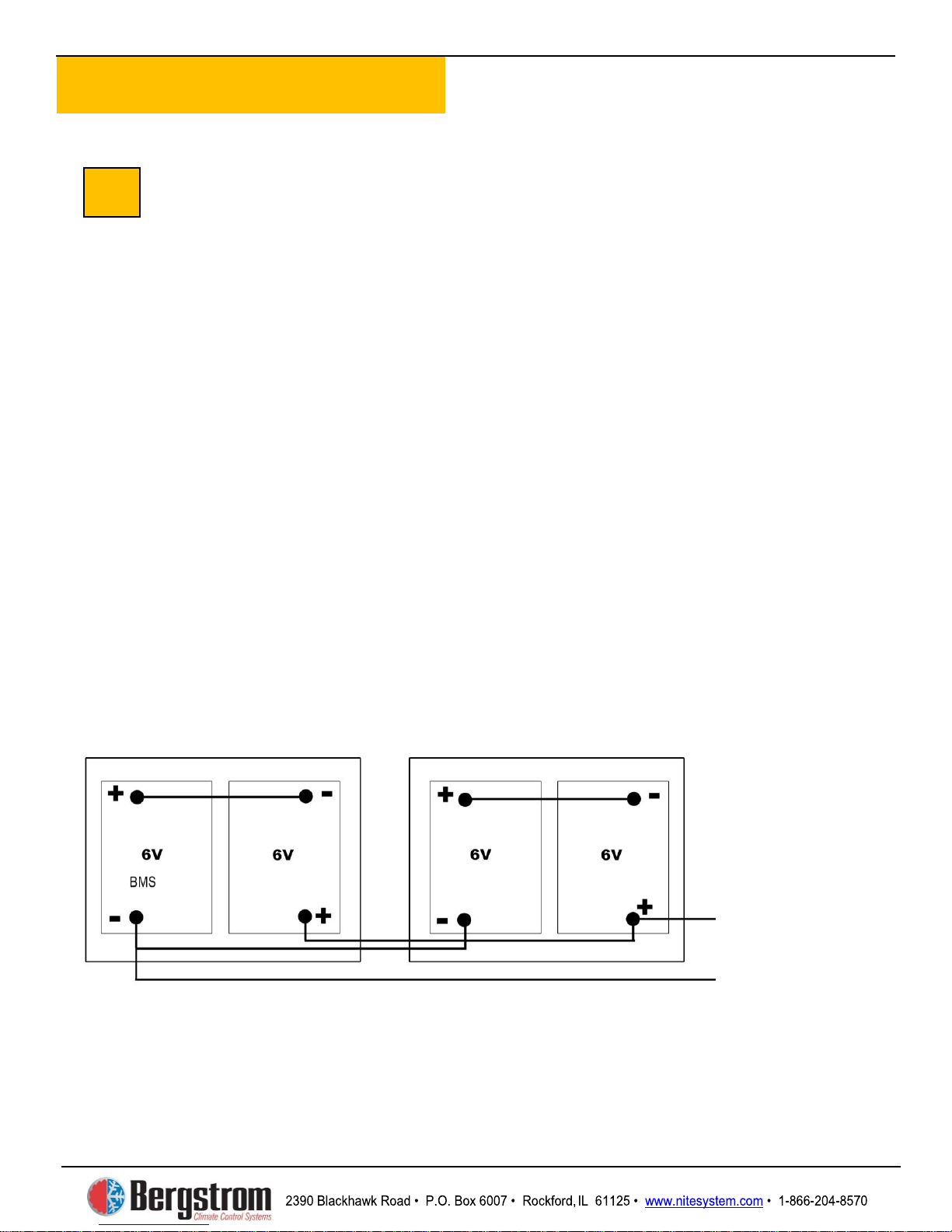
Directions for Wiring a 6-Volt
Series/Parallel, 4 Battery
Plus
Step 1: Install the two short battery
cables provided in the kit. These cables
connect the positive (+) of one battery
to the negative (-) of the other to create
a set or bank. We refer to this as a
series connection.
any other cables or wires to these
terminals.
Step2: For the positive to positive
parallel connections, measure and cut a
piece of red cable to the proper length.
Attach a ring terminal to each end using
a professional grade crimper. Place heat
shrink around each terminal and heat.
6a
Then loom it. Use this cable to connect
the positive (+) of one bank of batteries
to the positive (+) of the other bank of
batteries.
Step3: Repeat procedure for the
negative to negative connection using a
black cable. Then loom it. Use this
black cable to connect the
negative (-) of one bank of batteries to
the negative of the other bank of
batteries.
Now proceed to step 7.
Do NOT use truck frame as a ground
Connect positives here:
=12V
NITE
DO NOT connect
AC Unit, Heater, and
Separator
Connect negatives
here: AC Unit, Heater,
and Truck Battery
negative
Page 22
Electrical Installation
2-4
Page 23
Electrical Installation
2-5
Directions for Wiring A 12-Volt
Parallel, 4 Battery
Parallel is all positives connected
together and all negatives connected
together.
Step 1: For the positive (+) to positive
(+) parallel connections measure and
cut pieces of red cable to length. Attach
a ring terminal to each end using a
professional grade crimper. Place heat
shrink around each terminal and heat.
Then loom it. Use these cables to
connect all positive (+) terminals on all
4
6b
Step2: For the negative to negative
connections repeat procedure using
black cables. Then loom it. Connect all
negative (-) terminals of the 4
Plus
Now proceed to step 7.
Do NOT use truck frame as a ground
Connect
positives here:
negatives here:
NITE Plus
NITE
batteries together.
NITE Plus batteries.
AC Unit,
Heater, and
Separator
Connect
AC Unit,
Heater, and
Truck Battery
negative
Page 24
Electrical Installation
2-6
Page 25
Electrical Installation
2-7
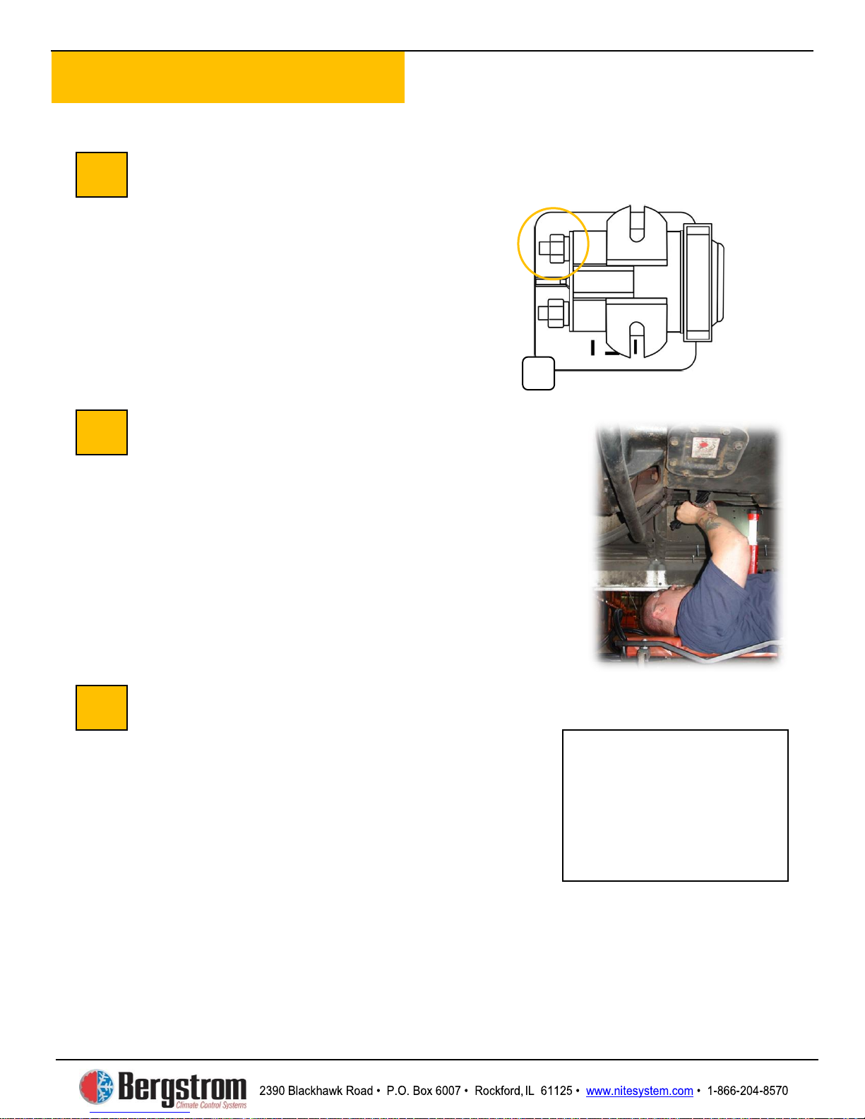
Connect Separator to the
Truck Batteries
Add ring terminals and protective looms to
ONE END of the negative and positive
cables, leaving about an inch of the cables
exposed for proper identification. DO NOT
CUT cables at this time…you will do that in
a later step.
Run Cables to Truck Batteries
Attach the positive cable to the main battery
terminal of the battery separator (photo A
above). Attach the negative cable to the
negative terminal on the
batteries
(see diagrams on pages 26 or 28). Zip tie the
cables together every 1 ½ feet. Run the
cables along the frame rail and over the
transmission to the other side to the truck
batteries.
Attach Cables to Truck Batteries
Cut the cables to the proper length and crimp
ring terminals. Attach negative side to truck
battery. Zip tie all wires to secure them in
place.
DO NOT CONNECT POSITIVE TRUCK
BATTERY CABLE YET.
CONNECT THIS CABLE LATER.
7
8
9
See Diagrams
2-3 to 2-6
A
NITE Plus
on Pages
WE WILL
Page 26
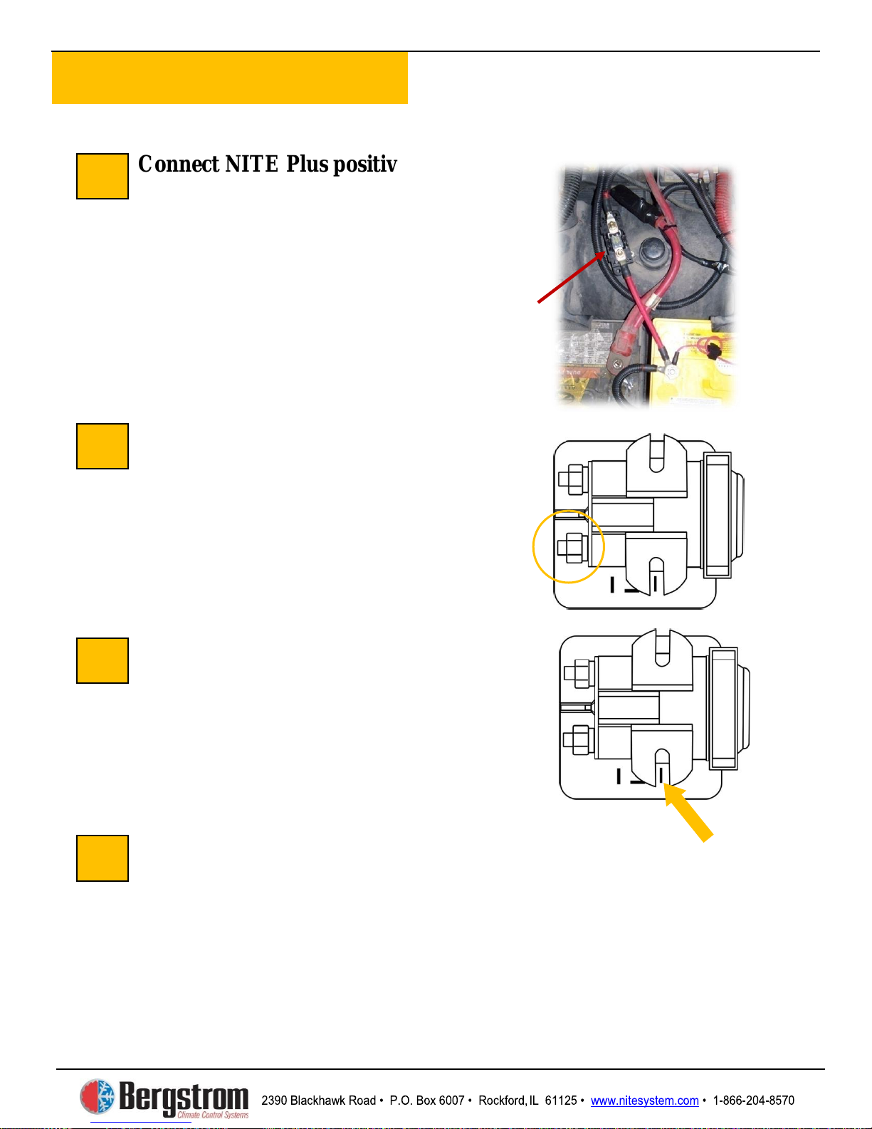
Electrical Installation
2-8
Connect NITE Plus positive power
cable to auxiliary battery location.
Before connecting positive cable make sure
blower control switch is in OFF position.
Install 100 amp fuse between power cable
and AGM positive battery post as shown.
Do not tighten posts at this time.
Connecting
Battery Separator
Using red battery cable, measure and cut to
proper length. Crimp ring terminals and heat
shrink. Connect one end to the most
appropriate positive (+) terminal of the NITE
Plus
auxiliary terminal of the battery separator.
Grounding the Separator
Connect one 16 gauge black wire from the
male spade terminal marked “ground” to the
negative battery terminal of either the truck
or
grounding the system will not recharge
batteries correctly.
Complete Electrical Wiring
Recheck and tighten all battery and separator connections. Zip tie cables where
necessary. Your wiring should look like the diagram on page 4 or 6.
Heater Installation
10
13
11
12
NITE Plus
NITE Plus Batteries to
Positive cable
and 100 amp
inline fuse
batteries. Connect the other end to the
NITE Plus batteries. Without proper
This completes the electrical section of the installation. If you are installing the
optional ESPAR heater proceed to heater section. If not, your installation is complete
and you may reconnect the truck batteries and connect positive cable from battery
separator described on page 26. Then proceed to the Checklist section.
Page 27
®
NITE Plus
SECTION 3
ESPAR HEATER
INSTALLATION
Page 28
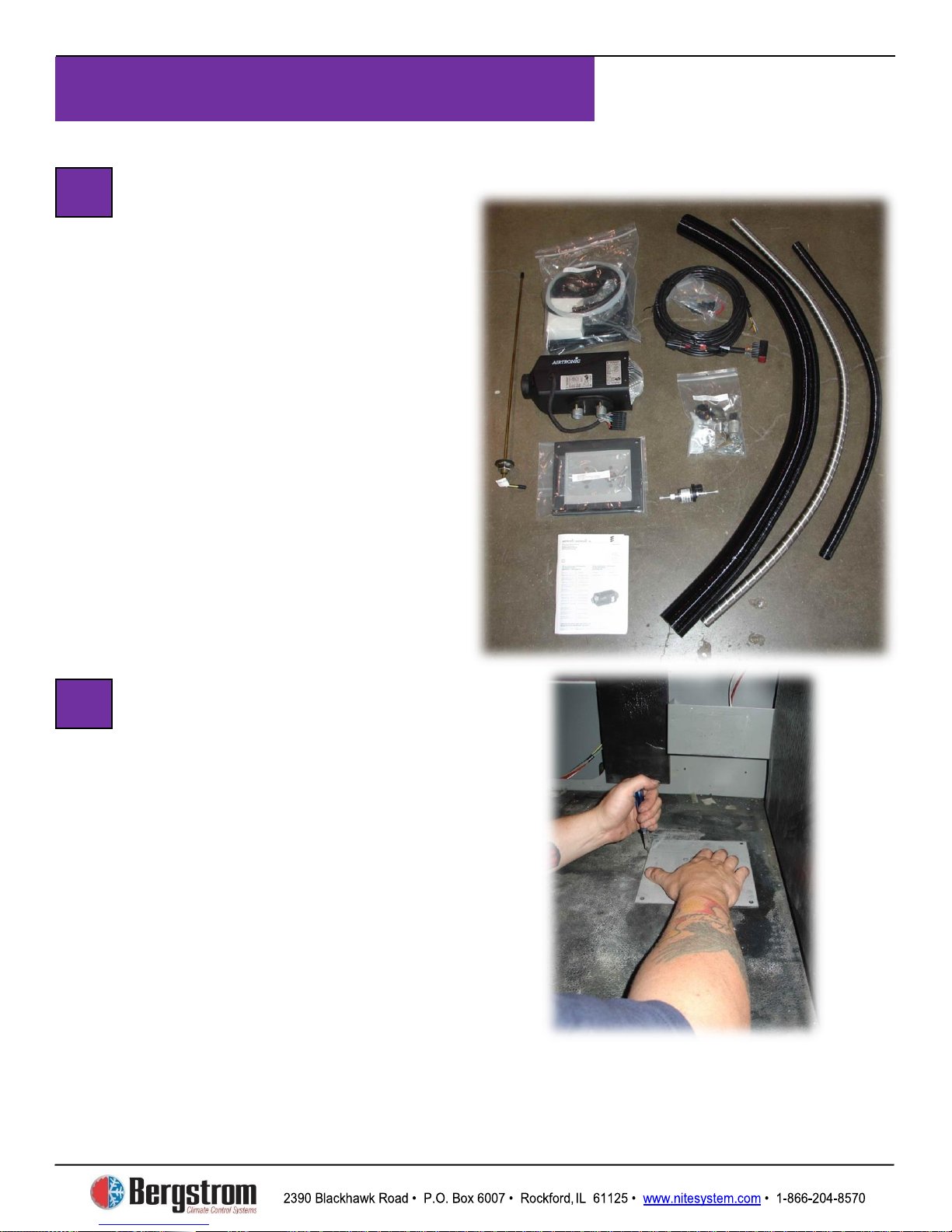
Espar Heater Installation
3-1
Prepare Heater Mounting Location
Choose the most appropriate location to
install the heater—in this case we have
chosen a side box floor location.
underneath truck for any obstructions or
supports.
template to cut an opening in the rubber mat.
Cut around the mounting plate, then remove
the piece of rubber to expose truck floor.
1
2
Unpack Heater Parts
Take out the parts to the heating unit.
NOTE: Do NOT use NITE duct
or OE ductwork for heater venting.
Use the mounting plate as a
Check
Page 29
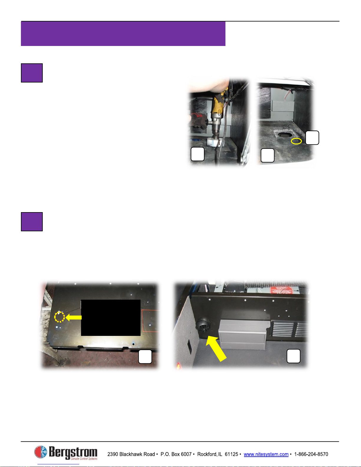
Espar Heater Installation
3-2
Drilling Outlet Hole
for Heat Unit
Mark the floor of the truck using the 5
small holes of the mounting plate.
Remove mounting plate, place a 4 ¼″
hole saw over the middle of the floor
marks (A), and drill the outlet hole for
the heater, intake, exhaust and pickup
tube (B). Also drill a 1/2″ hole
approximately 1 to 2″ from mounting
plate corner (C).
Install Sleeper Heat Vent
Select location for the vent in the lower left side of the center
support wall closest to heater. Drill a 2 ½″ hole (A) to allow
distribution of heat into the sleeper. After hole is drilled, use
5/16″ x 1″ self-tapping screws to attach heat port then snap
louver into place (B).
A
B
3
4
C
B
Drill 2 1/2″
Heater Vent
Hole for
Page 30
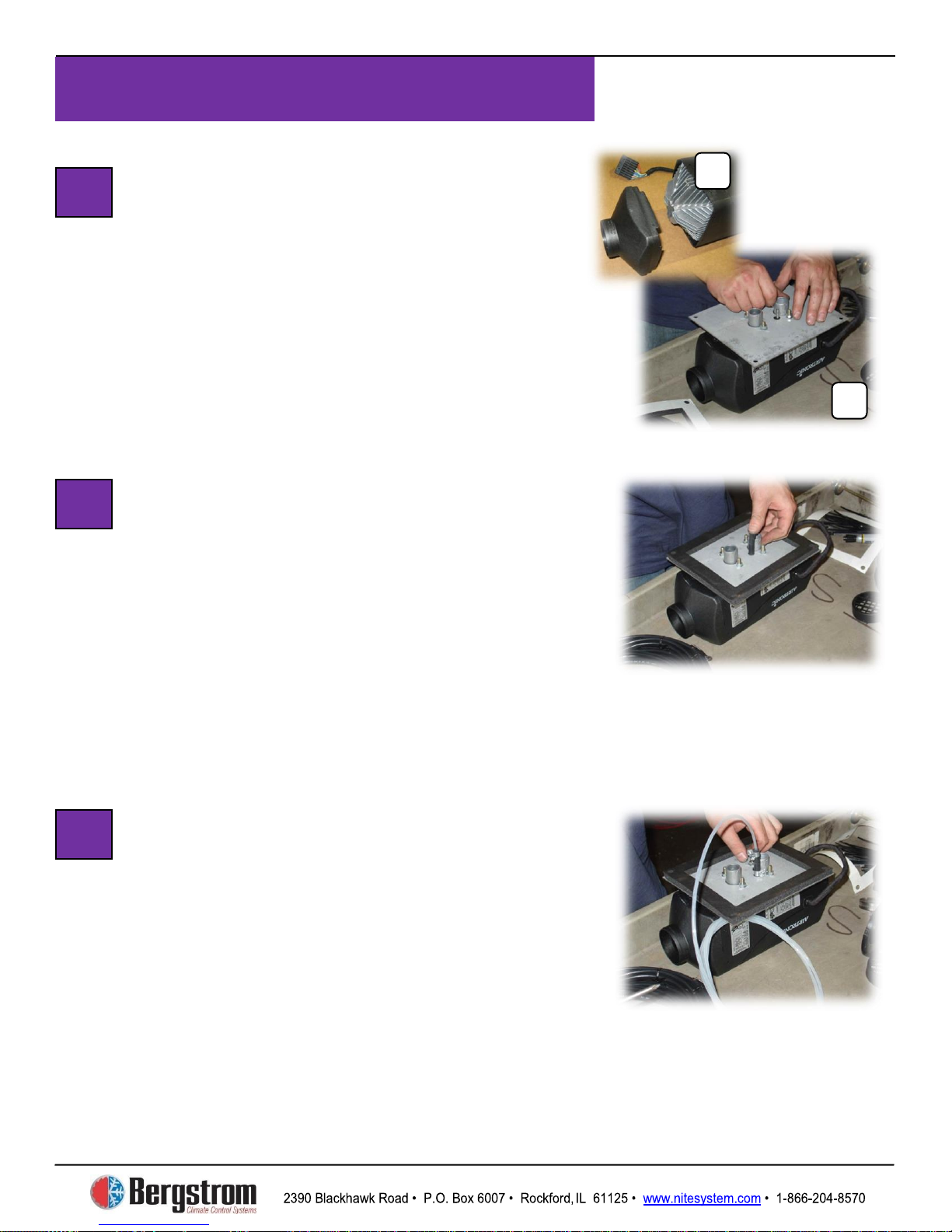
Espar Heater Installation
3-3
Heater Unit Assembly –
Attaching Mounting Plate
Snap end cap on heater unit (A). Place
mounting plate over heater unit (B). Attach
with flat lock washers and 10mm lock nuts—
tighten down securely.
Heater Unit Assembly – Attach
Gasket and Fuel Line Connection
Peel off backing from gasket and place gasket
over mounting plate edges, sticky-side down.
Place small black rubber fuel line connector
over the fuel intake tube and push down. Place
a small clamp over connector, push to bottom
and tighten.
Heater Unit Assembly –
Attach Fuel Line
Now take the clear pick up tube, place a small
clamp over it, and push the tube all the way to
the bottom of the fuel intake tube. Place clamp
flush with top of black connector and tighten
securely.
5
6
7
B
A
Page 31
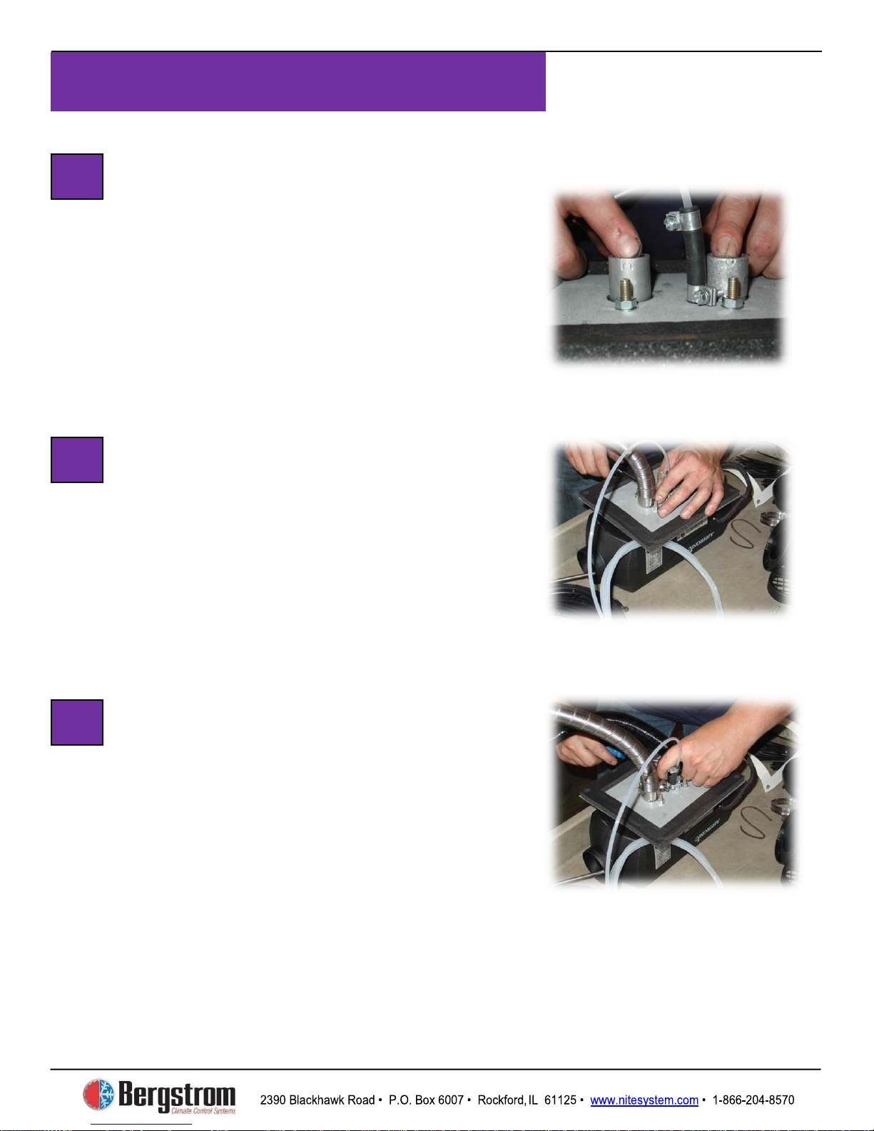
Espar Heater Installation
3-4
Heater Unit Assembly –
Identify Intake and Exhaust Ports
Look closely at the two small metal tubes.
One has an arrow pointing out away from
the unit—this is the exhaust. One has an
arrow pointing in towards the unit—this is
the intake.
Heater Unit Assembly –
Attach Exhaust Hose
Take the heavy duty silver metal hose and
place a large, heavy duty clamp over the
end of it. Place the hose and clamp over the
exhaust tube, push all the way down, and
tighten securely.
Heater Unit Assembly –
Attach Intake Hose
Take the black flex hose and place a small
clamp over the end of it. Place the hose and
clamp over the intake tube, push all the way
down, and tighten securely.
Heater is now ready to install in the
truck.
8
9
10
Page 32
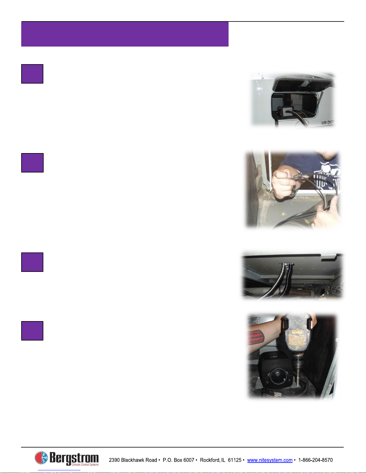
Espar Heater Installation
3-5
Prepare to Mount Unit
Check to make sure truck batteries are still
disconnected.
mounted over the 4 ½″ hole that was drilled
earlier. Make sure hoses and tubes don’t get
tangled or caught on anything.
Run Power and Fuel Pump Wires
Through Floor
Run the power wire and fuel pump power
wire through the rubber mat. Next, slip on the
grommet, then run the wires out the hole in
the truck floor and down under the truck. Seat
grommet into hole, and push rubber mat back
down.
Run Lines Through Cab Floor
Feed exhaust hose, intake hose, and fuel line
through the 4 1/2″ hole, making sure they are
not bent, crimped or rubbing on the side of the
hole.
Mount Heater Unit to Cab Floor
Make sure that the heater unit is set with the
fan (intake) end opposite the 2 ½″ hole for the
vent/louver drilled earlier. Set unit flush to
floor and attach with a self-tapping screw at
each corner of the mounting plate.
11
13
14
12
Carry unit into truck. It will be
Page 33
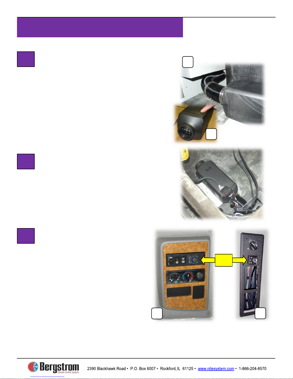
Espar Heater Installation
3-6
Attach Heat Line to Sleeper Vent
Take the black metallic flex tube,
measure and cut length to run from
heater unit to louver/vent opening (A).
Place two clamps over ends of tube, and
clamp tube to heating unit and louver.
Tighten clamps securely
but do not over tighten. Snap Intake Grill
onto intake end of heater (B). Keep this
area clear of debris.
Attach Wiring Harness
Attach plug end of wiring harness into
wiring plug at bottom of heating unit.
Be sure the lock-in pin seats securely.
Install Heater Control
into
Panel or OEM control panel
You can install the heater control
in either the OEM control panel (A)
or the
panel (B). Remove the faceplate
from the location you select and
follow steps 18 – 20 for installation
instructions.
15
16
17
B
B
A
Or
NITE Plus Control
NITE Plus control
Page 34
Espar Heater Installation
3-7
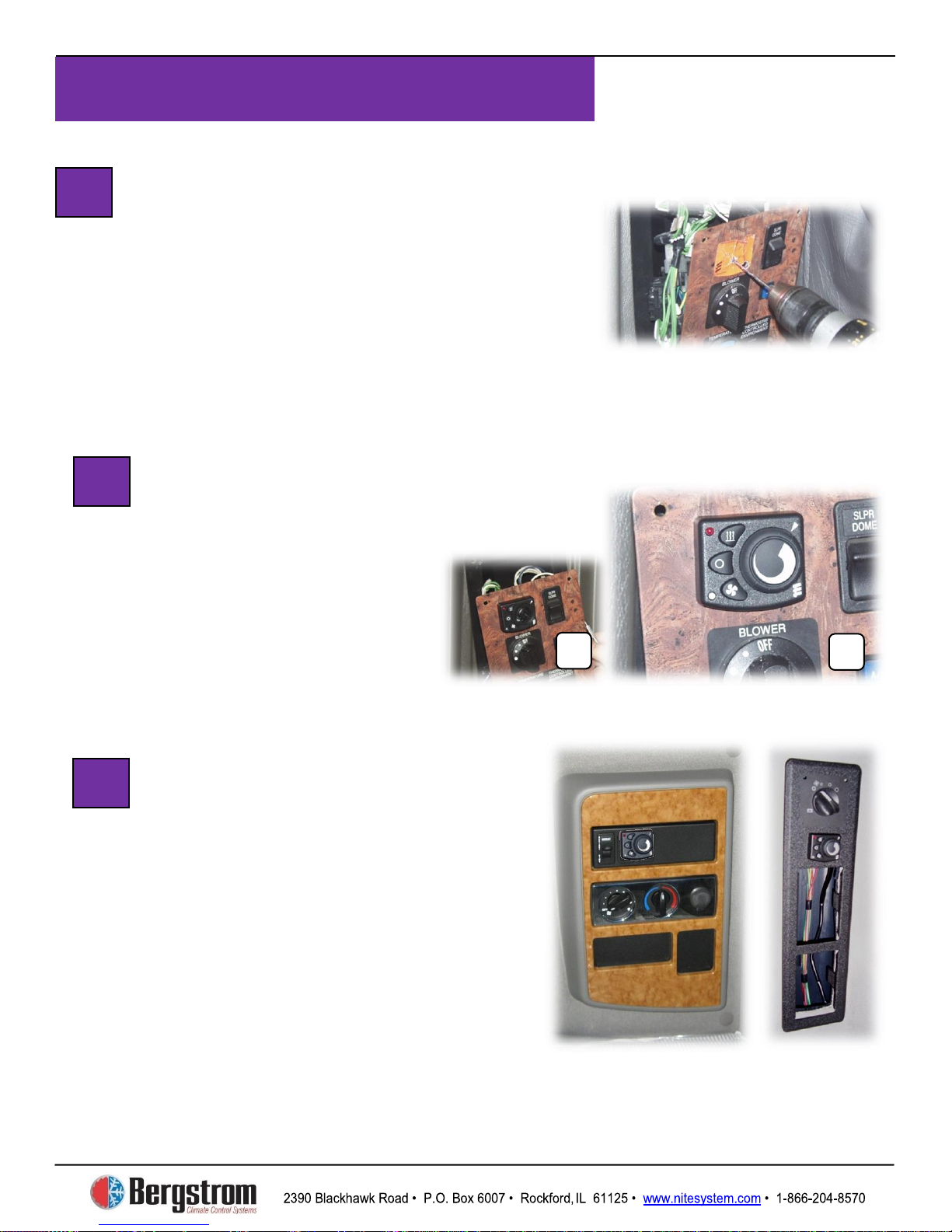
Attach Template to Faceplate – Drill
Take the sticker template that came with the
Espar controller and place it on the panel.
Drill holes through panel for wiring and for
attaching screw as indicated on sticker. Pull
sticker off after holes have been drilled.
Mount Heat Controller and Knob
Now feed controller wiring harness wires
through large hole to backside of panel.
Remove controller knob.
Screw controller to panel
with small screw (A).
Replace controller knob (B).
B
18
19
Re-attach Faceplate
Carefully tuck all wires behind the corner
faceplate, and re-attach faceplate with screws
that were removed earlier. Run control
harness wires from the corner control panel,
along bed and in parallel with other wiring
down toward the heater.
20
Page 35
Espar Heater Installation
3-8
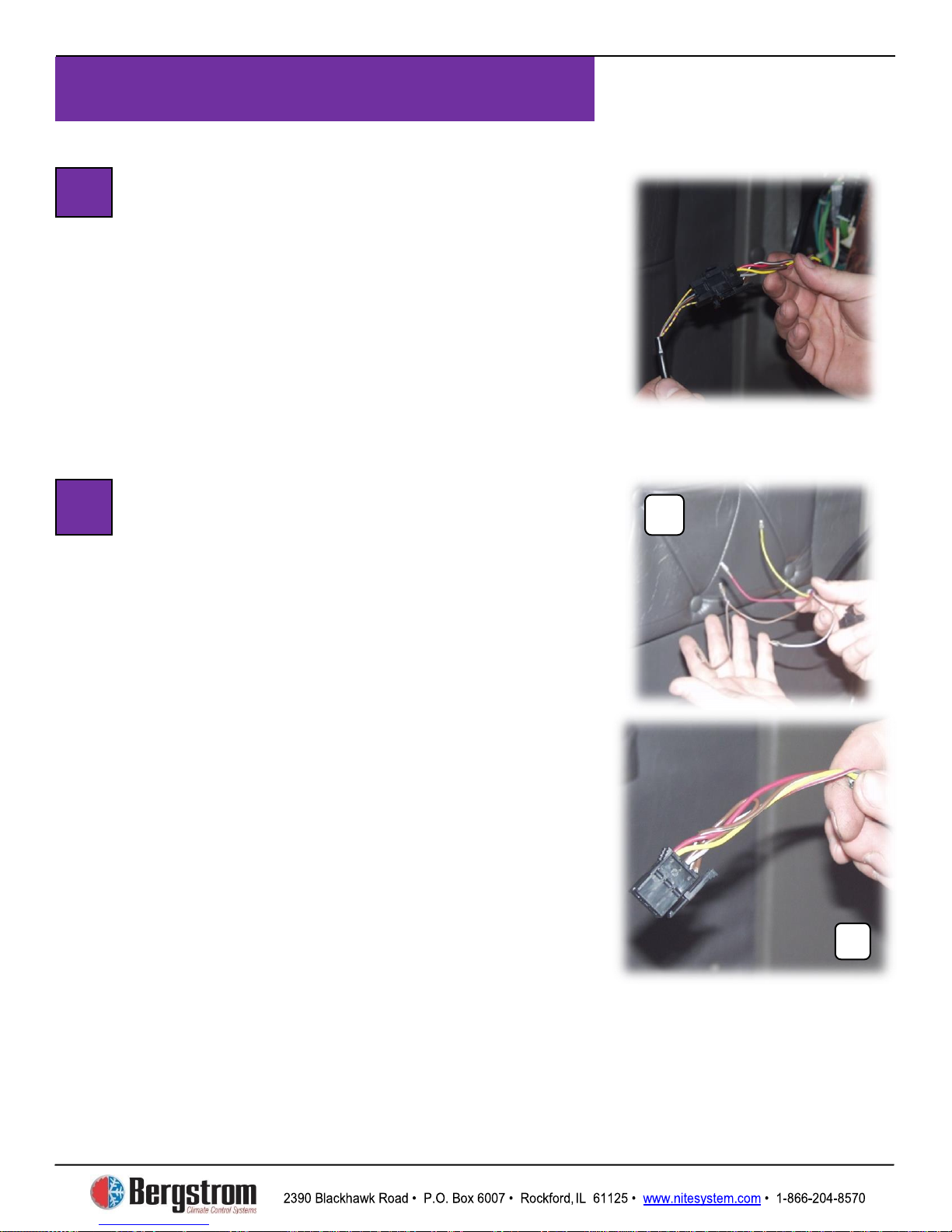
Install Connector on Mini Controller
Harness
Connect ends of wire harness to plastic
connector in this way: 1 = red, 2 = yellow,
3 = brown, 4 = solid grey, 5 = yellow with
violet stripe.
Attach Wire Connector from Heater
Control Harness
Route the control cable along the bed towards
the heater control panel. Use zip ties as
needed. Strip off 6″ of black outer jacket from
cable coming from heater. Fold all wires back
and cut off the outer jacket, the blue, solid
gray and solid brown wires. Save the brown
wire and make a jumper wire. Strip down ends
of solid brown wire. Connect one end of solid
brown jumper to brown/white wire. Add clips
to ends of wires and crimp on with crimper.
On connector, the numbers 1, 3, and 5 are on
one side, 2, 4, and 6 are on the other. Insert
wires into plug as follows:
1 = red, 2 = yellow, 3 = brown jumper,
4 = gray with red stripe, 5 = other end of
jumper including brown/white wire. Now
connect the heater control harness to the
controller harness.
22
21
A
Page 36
Espar Heater Installation
3-9
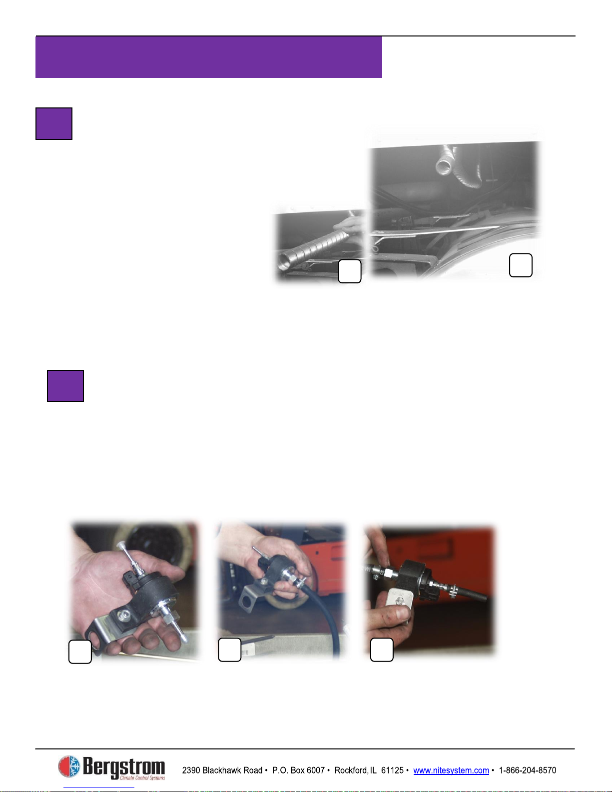
Assemble the Fuel Pump Mount and Hoses
Take rubber mount bushing and L bracket and put them together to
make mounting bracket for fuel pump. Slide fuel pump into rubber
bushing (A). Take plastic caps off both ends of fuel pump. Attach large
fuel hose to larger diameter end (B), figure out length needed to go out
center hole of L bracket, and cut off excess. Secure with clamp.
Attach small precut hose to smaller diameter end of the fuel pump and
secure with clamp (C).
A
24
Finishing Intake and
Exhaust Hose Installation
First, attach intake air tube to truck structure
with zip ties. Put cap on bottom of intake tube.
Next, run exhaust hose toward back of cab
(A), attach with clamps to
the structure of the truck.
Cut off excess exhaust hose,
and place End Sleeve on the
end of the hose (B).
NOTE
from wiring or flammable material.
23
: HOT – Keep exhaust hose away
Page 37
Espar Heater Installation
3-10
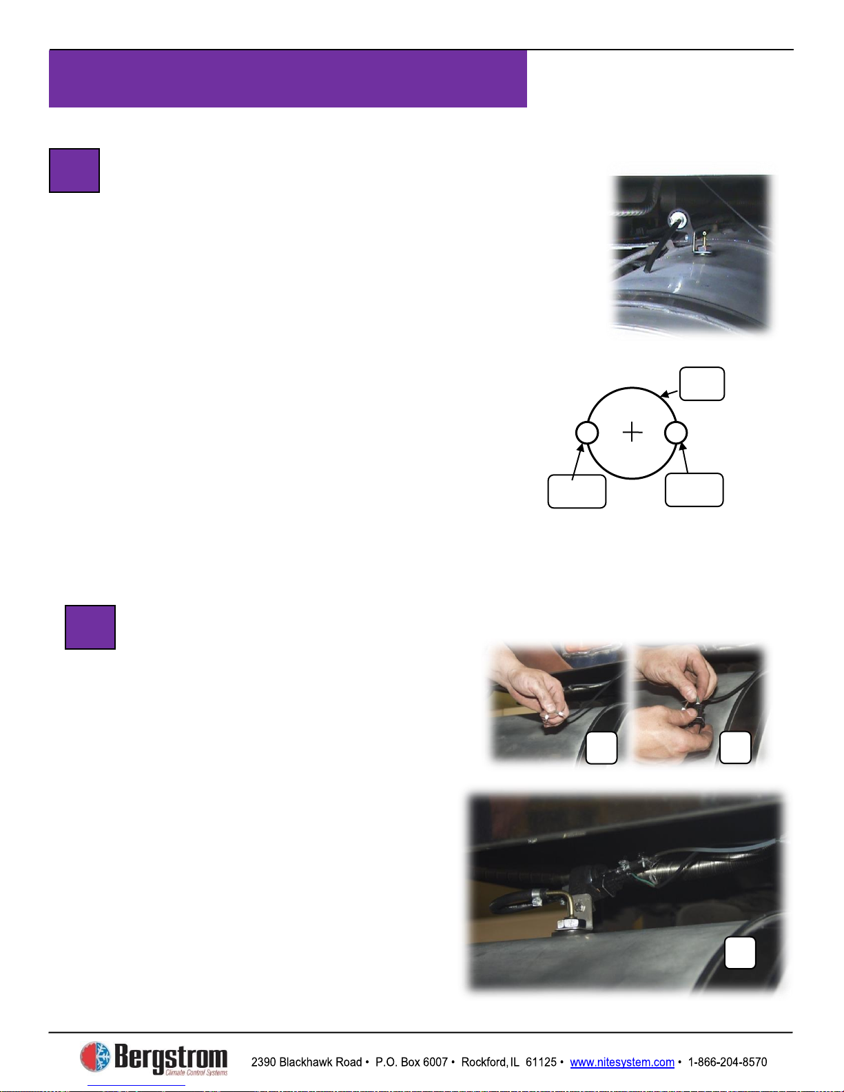
Drill Hole in Fuel Tank, Insert
Pickup Tube and Mount Fuel
Assembly
Use a 1″ hole saw to scribe initial location for
two outer holes. Drill the two outer 1/4″ holes
centered on scribe. Then complete drilling the
1″ hole. See diagram A.
possible drill holes in the fuel sender block off
plate. Slide pickup tube into fuel tank through
hole, install with bottom washer then put on
rubber seal and place metal washer on top of
pickup tube followed by pump mounting
bracket and nut. Tighten slightly. Put clamp
over end of large fuel line from fuel pump,
attach to pick up tube and clamp down.
Finish snugging up large nut, but do not over
tighten. Cut off excess from small feeder tube
fuel line and attach to fuel pump. Secure with
Prepare Power Harness and Attach
to Fuel Pump
Measure and cut power harness wires to
appropriate length. Strip wires, put on rubber
boots, then attach ends and crimp (A). Attach
wires to plug: 1 = green, 2 = brown.
Make sure rubber boots are seated to keep
out moisture (B). Connect the power harness
spring loaded plug to the fuel pump (C).
Secure all wires and hoses with zip ties.
A
B
25
26
1″
1/4″
Diagram A
1/4″
Option: When
Page 38
Espar Heater Installation
3-11
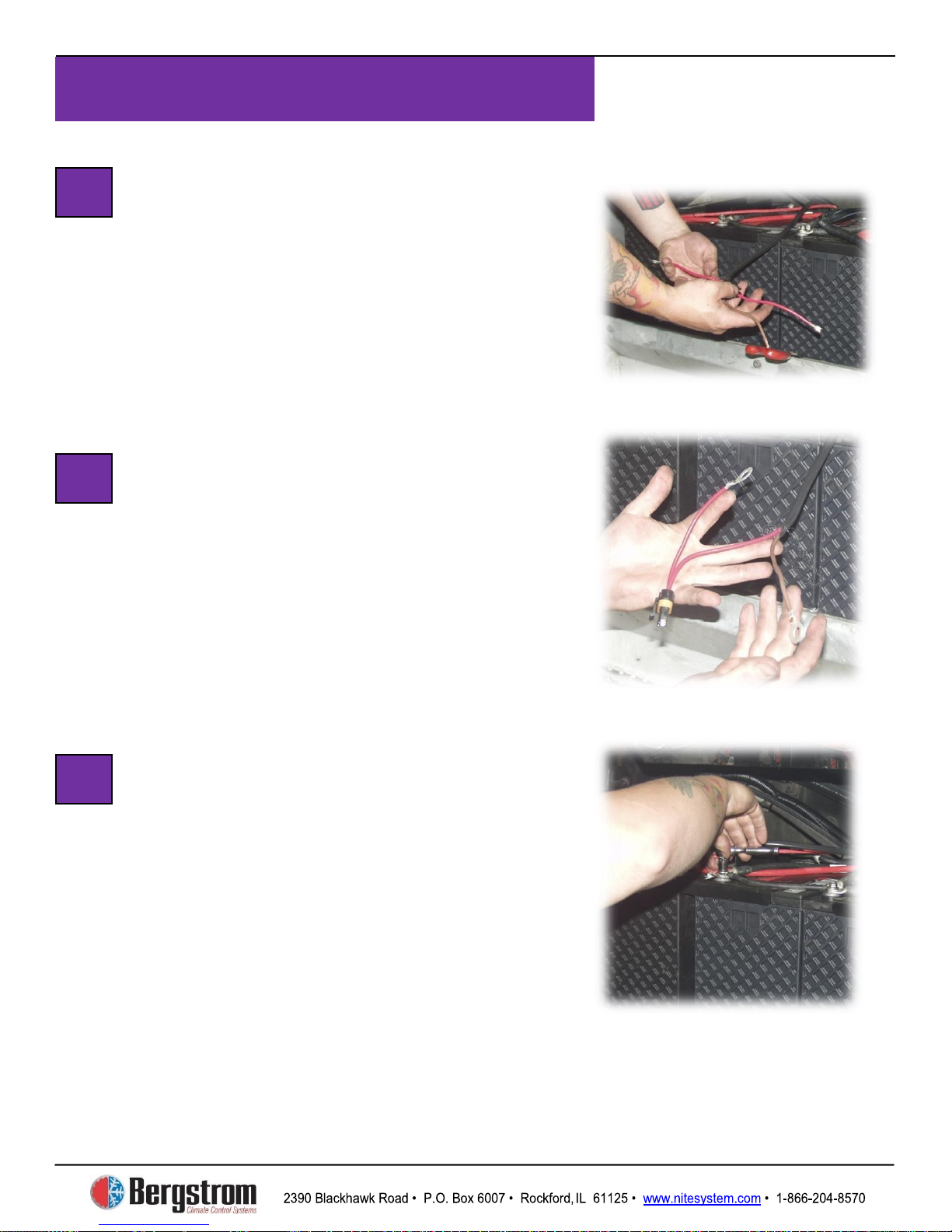
Run Heater Unit Power Cable
to
Take the heater unit power cable, run it under
the truck (attach with zip ties where
necessary) over to the
Strip back outer cover to expose two inner
wires.
Attach Connectors
Strip end off brown wire. Before stripping
red wire, put the housing for the fuse bracket
on, and pull the red wire through. Now strip
the end of the red wire, attach fuse bracket
and crimp down. Pull red wire back into fuse
bracket housing. Push rubber seal into place.
Attach ring terminal to ground wire and
crimp.
Attach Wires to
Batteries
Connect heating unit ground wire to ground
terminal of
heating unit positive wire to positive terminal
of
into fuse bracket. Tighten all connections.
YOU CAN NOW RECONNECT THE
TRUCK’S BATTERIES TO TEST THE
SYSTEM.
27
28
29
NITE Plus Batteries
NITE Plus batteries.
NITE Plus batteries. Insert 20 amp fuse
NITE Plus batteries. Connect
NITE Plus
Page 39
®
NITE Plus
SECTION 3
WEBASTO HEATER
INSTALLATION
INSTALLATION
Page 40

4-1
Webasto Heater Installation
2390 Blackhawk Road • P.O. Box 6007 • Rockford,
IL 61125 • www.nitesystem.com • 1-866-204-8570
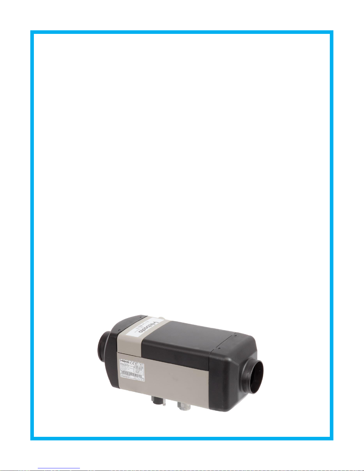
DO NOT USE NITE DUCT FOR HEAT VENT.
ATTN: Refer to Webasto manual for all heater installation
instructions.
http://techwebasto.com/redirect/heater_main/5001118B.pdf
Page 41

®
NITE Plus
SECTION 5
CHECKLIST
Page 42
Checklist
5-1
Now that you’ve completed installation, it’s time to check the systems to make sure
Control Position
Capacity Setting
Blower Speed
Compressor speed
1 (LOW)
Low
Low
Low
2 (MEDIUM)
Medium
High
Low
3 (HIGH)
High
High
High
everything is working properly. To help you do that, we’ve prepared a brief
description of how the NITE Plus operates, and several checklists to help you make
sure everything is in working order.
1. System and controls overview
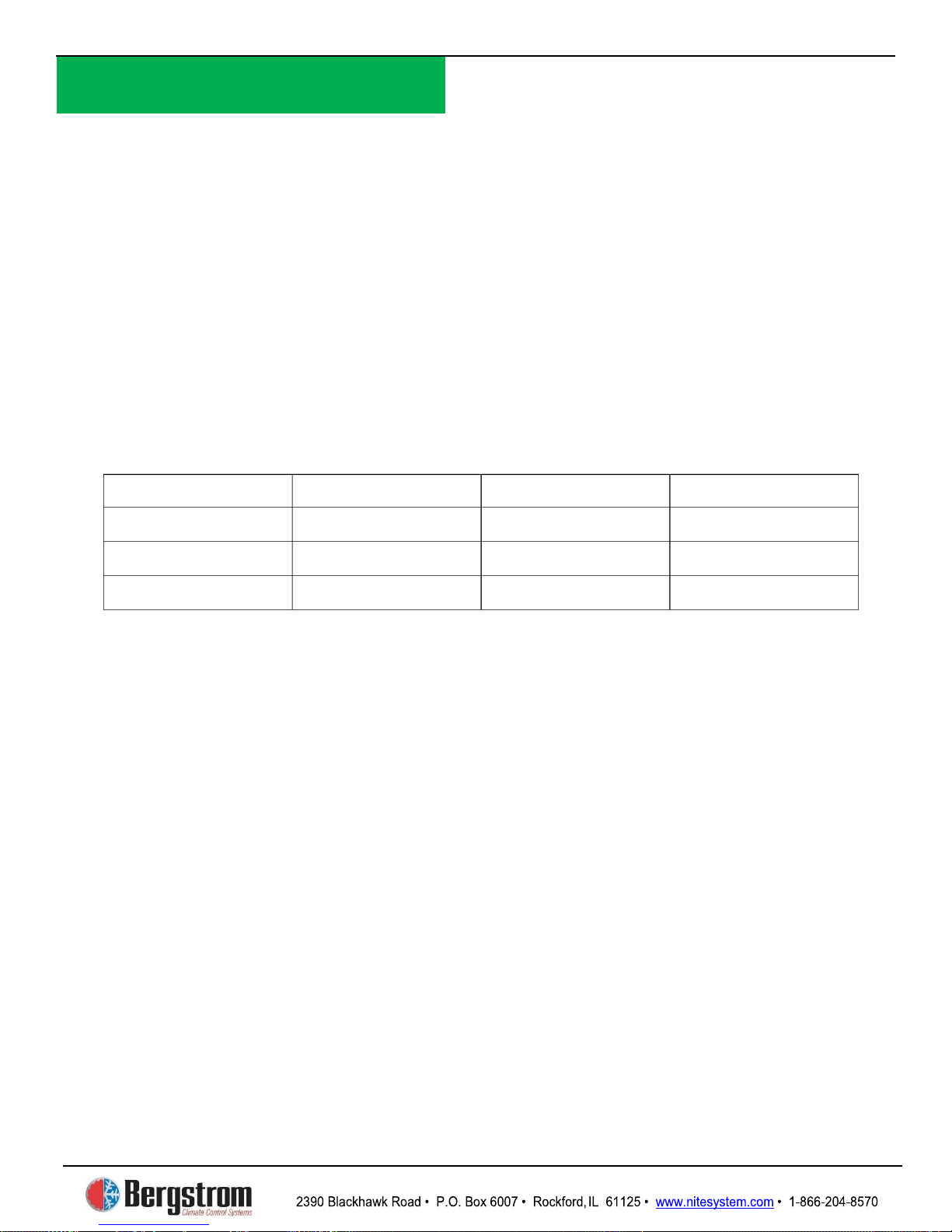
The NITE Plus has a 3-position control: Low, Medium, and High. For each of these
positions, the compressor speed and evaporator blower settings are different. This
table shows how the compressor and blower are set for each control position:
NOTE 1: Airflow does not change when switching the control from MEDIUM to
HIGH. Only the compressor speed changes.
NOTE 2: In addition to the evaporator blower and the compressor, the NITE Plus
also uses a condenser fan. It is located (along with the compressor and evaporator
blower) inside the NITE Plus unit. It draws air from below the sleeper floor to
cool the condenser coil, and then expels the heated air to the outside. The
condenser fan speed remains the same for all control positions.
NOTE 3: Low voltage cutout – unit will turnoff once NITE Plus batteries are
below 11.3 volts. Also will not start if voltage is too low
Page 43
Checklist
5-2
Component
Function
How to check it
Blower (evaporator)
Blows cold air to the sleeper
area through the ducting. This
is a 100% recirculating system
with two air intakes located on
the top and side of the NITE
Plus unit.
Switch the NITE Plus control
to LOW (Position 1). You
should feel air coming from the
louvers. Next, switch the
NITE Plus control to
MEDIUM (Position 2). You
should feel an increase in
airflow coming out of the
louvers.
NOTE: Make sure nothing is
blocking the recirculation air intake
opening on the NITE Plus unit.
Fan (condenser)
Pulls outside air from under the
sleeper floor to cool the
condenser coil, and then expels
the heated air outside.
Go under the sleeper
underneath the truck and check
to make sure that air is coming
OUT the rectangular condenser
air outlet when the NITE Plus
unit is running. Then check the
triangular inlet to make sure air
is going IN.
Compressor
Compresses and pushes the
refrigerant through the NITE
Plus unit refrigerant loop.
The best way to check that the
compressor is running is to feel
the compressor speed changes
when the control is switched
from MEDIUM to HIGH. Set
the control to MEDIUM, and
lift up the bed so you can hear
the sound changes. Wait 1
minute. Then set the control to
HIGH—you should notice a
change in the vibration and
sound of the NITE Plus unit.
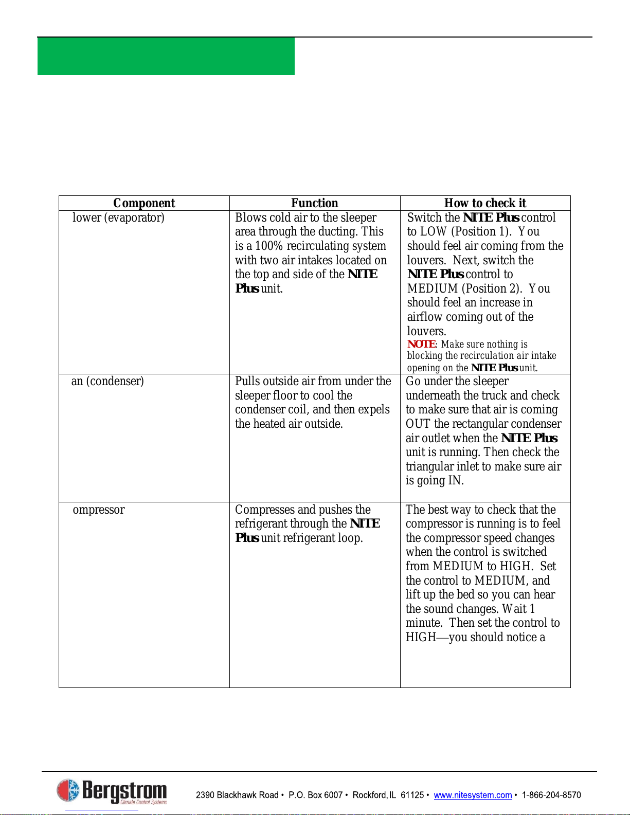
2. System components checklist
run properly when the
Follow this table to check that the individual components of the NITE Plus
unit is ON.
Page 44

Checklist
5-3
3. Electrical and temperature checklists
Use the following checklist to check that your
is operating within the
correct electrical and temperature ranges.
Electrical power
unit’s voltage. On the power supply cables (red and
black cables) located close to the unit, there is a black connector from which the
batteries are fully
control to HIGH,
use a clamp-on inductive ammeter to measure the current on the unit power
supply RED cable. You should read between 27 and 35 amps depending on
ambient temperature. On a hot day you should read higher amps, on a cool day,
Temperature
unit control
on and set to high. After the unit has operated for a minimum of 20 minutes,
louver temperatures. With the sleeper curtain closed you
should see a temperature difference of 13-25 degrees from the outside
temperature. Please keep in mind High solar loads and high humidity will vary
unit pulls air from outside under the sleeper floor to cool down
the condenser coil. The air is then expelled to the outside, also under the sleeper
running in HIGH, locate the condenser air outlet
under sleeper—it is a rectangular opening with a screen. Measure the
F higher than the
4. Separator checklist
4.2 Check to ensure all electrical components/connections have been installed
3.1 Check the NITE Plus
voltage can be read. When the NITE Plus auxiliary (aux)
charged you should read between 12 and 12.5 volts.
3.2 Check the NITE Plus unit’s current. Set the NITE Plus
lower amps.
3.3 Air temperature at louvers
First, precondition your sleeper compartment. Turn the NITE Plus
check your NITE Plus
the performance of the unit.
3.4 Condenser outlet temperature
The NITE Plus
NITE Plus
floor. With the NITE Plus
temperature of the air coming from this outlet. It should be 10
outside temperature.
4.1 Check to make sure all electrical connections are tight and secure.
according to instructions and diagrams.
Page 45

Checklist
5-4
4.3 Check voltage with engine OFF
First, check that the voltage on the TRUCK batteries is the same as the voltage
on the separator (use the ground terminal to check separator voltage). Both
Next, check that the voltage on the aux batteries is the same as the voltage on the
separator (use the ground terminal to check separator voltage). Both voltages
With the engine ON, check the voltage at the truck batteries. It should be higher
Next, wait for the truck batteries voltage to reach at least 13.2V. You may need
to increase the engine RPM to raise voltage. At 13.2V, the separator should
close and start charging the aux batteries—you should hear the separator make
Now check the voltage of the aux batteries. It should be higher than the voltage
when the engine is OFF, and should be approximately the same voltage as the
You can double check that the separator is allowing the aux batteries to charge
by measuring the amps going to the aux batteries using a clamp-on inductive
ammeter. Place it on the 4 gauge cable that connects the separator to the aux
NOTE
Older starting batteries will change time needed to charge aux batteries and may
cause decrease in runtime.
Old batteries do not hold charge long enough requiring alternator to continuously
charge starting batteries.
Separator looks for 13.2 volts on start batteries prior to charging aux batteries.
voltages should be approximately 12V.
should be approximately 12V.
4.4 Check voltage with engine ON
than when the engine is OFF (>13V).
an audible “click”.
truck batteries.
batteries positive terminal. It should read >0 amps.
:
 Loading...