

Page 1

Installation Manual
Classic Sleeper including
T600, T660, T800 and W900
2390 Blackhawk Road ● P.O. Box 6007 ● Rockford, IL 61125 ● www.nitesystem.com ● 1-866-204-8570
Page 2

1-2
Kenworth T600-T660-T800-W900 rev 10/7/13
Installation Procedures
Table of Contents
Introduction
Before You Start
Parts List
Tools Required
Installation Procedures
Electrical Installation
Espar Heater Install
1-3
1-4
1-5
1-8
1-9
2-1
3-1
4-1
5-1
6-1
Wiring Diagrams
Operating Instructions
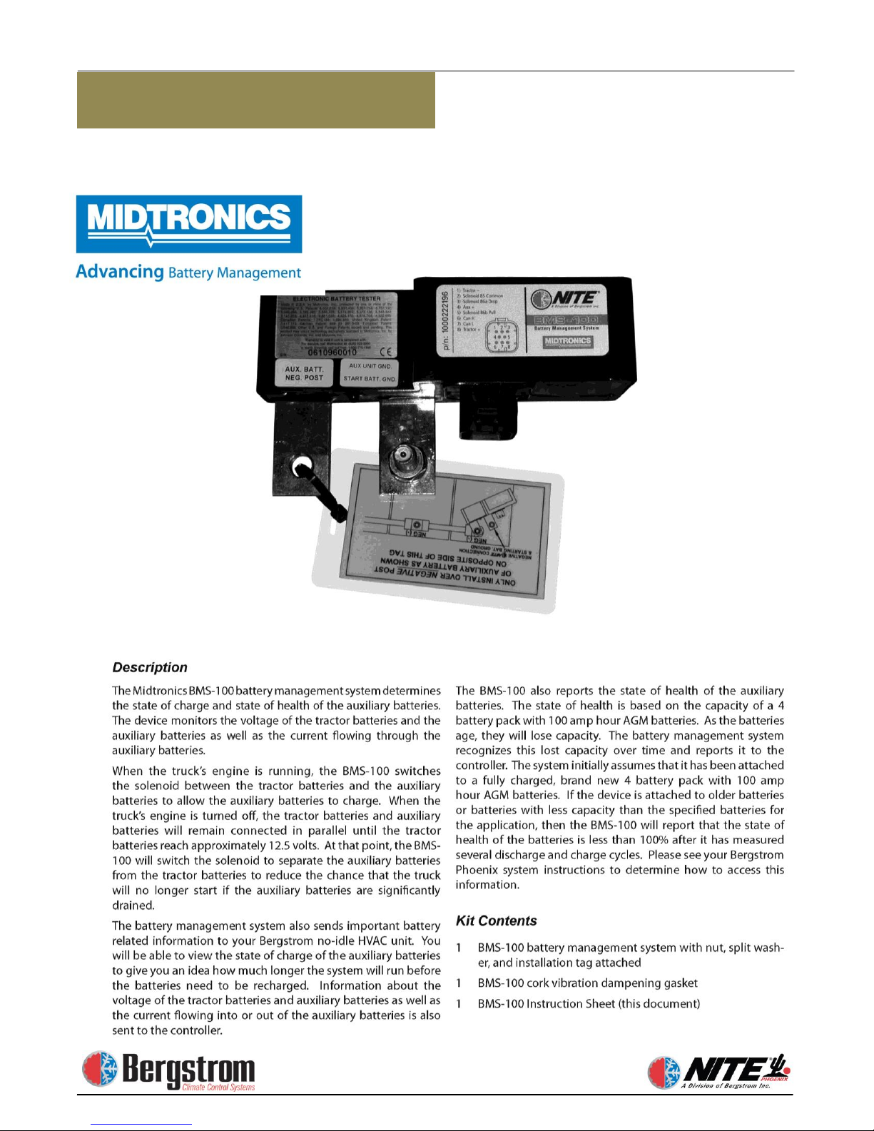
Battery Management
Webasto Heater Install
Page 3

1-3
Kenworth T600-T660-T800-W900 rev 10/7/13
Installation Procedures
Congratulations. You have chosen the
premier no-idle climate control system on the
market today—the NITE® Phoenix from
Bergstrom.
The NITE Phoenix is a powerful 12V
rechargeable DC system that keeps sleeper
compartments cool in hot weather and warm in
cold weather (with optional heater) without
having to idle the truck’s engine—and without
a genset. It not only dramatically reduces fuel
burned, it’s also very environmentally friendly.
Your NITE Phoenix is a self-contained,
hermetically sealed, compact A/C system
that produces approximately 7,500 BTU/h
and has been quality engineered for years of
reliable service. The system operates
independently from your truck’s engine
using its own deep cycle batteries that are
completely separated from the truck’s
starting batteries.
The deep cycle batteries used are the most
advanced ever—and will efficiently power
the system for 7 to 9 hours. The batteries are
then fully recharged after just 4 to 6 hours of
driving.
Add it all up, and you have a revolutionary
no-idle system that will save you money and
fuel year after year—the NITE Phoenix
from Bergstrom.
Introduction
NOTE:
The NITE Phoenix A/C system is designed
to maintain a comfortable temperature inside
the sleeper without running the engine.
For optimal comfort, the curtain between the
cab and the sleeper must be closed when
using the unit. To enhance cooling efficiency
during the day, solar reflectors or curtains
should be placed over windshield and all
windows to block sunlight from entering the
cab and sleeper.
The NITE Phoenix A/C unit will not pull
down a hot sleeper that has been sitting in the
sun without the factory A/C running. To
assist the NITE Phoenix unit in cooling
down the sleeper, start the engine and run the
factory A/C until desired temperature is
reached. The NITE Phoenix unit will then
maintain a comfortable temperature
depending on solar load & ambient
temperature.
An alternator providing 30 amps over OE
spec is required for recharging
Page 4
1-4
Kenworth T600-T660-T800-W900 rev 10/7/13
Installation Procedures
Before You Start
A typical installation of the NITE Phoenix
generally takes between 8 to 10 hours, although
your particular situation may vary. This manual
contains step-by- step installation instructions. It
is divided into three categories:
● General installation
● Electrical installation
● Heater installation (optional)
There is also a section on how to check your
NITE Phoenix to make sure the installation was
successful, and a section on how to operate your
NITE Phoenix.
If relocation or reinstallation of any pre-installed
equipment is necessary for installation of the NITE
Phoenix equipment - please refer to the components
manufacturer's instructions or safety guidelines for
proper installation.
Before you start, we highly recommend doing the
following to help make your installation as easy
as possible.
1. Lay out all parts and check to make sure
you have all parts listed on the parts list.
Depending on truck, some hardware
may not be used. If you are missing any
parts, please call 1-866-204-8570.
2. To prevent damage to compressor, keep the
NITE Phoenix unit in an upright position
at all times. If unit is tipped, place back in
upright position for a minimum of 6 hours
prior to running.
3. Check the list of tools needed for
installation and make sure you have all of
them. Keep all tools within easy reach.
4. Look through the whole installation
manual to get an understanding of the order
in which components are installed.
5. Make sure you have good lighting and
enough space to work in.
6. You may want to get an assistant to help
you to reduce the number of times you
have to climb in and out of the cab.
7. Make sure you wear all appropriate safety
equipment.
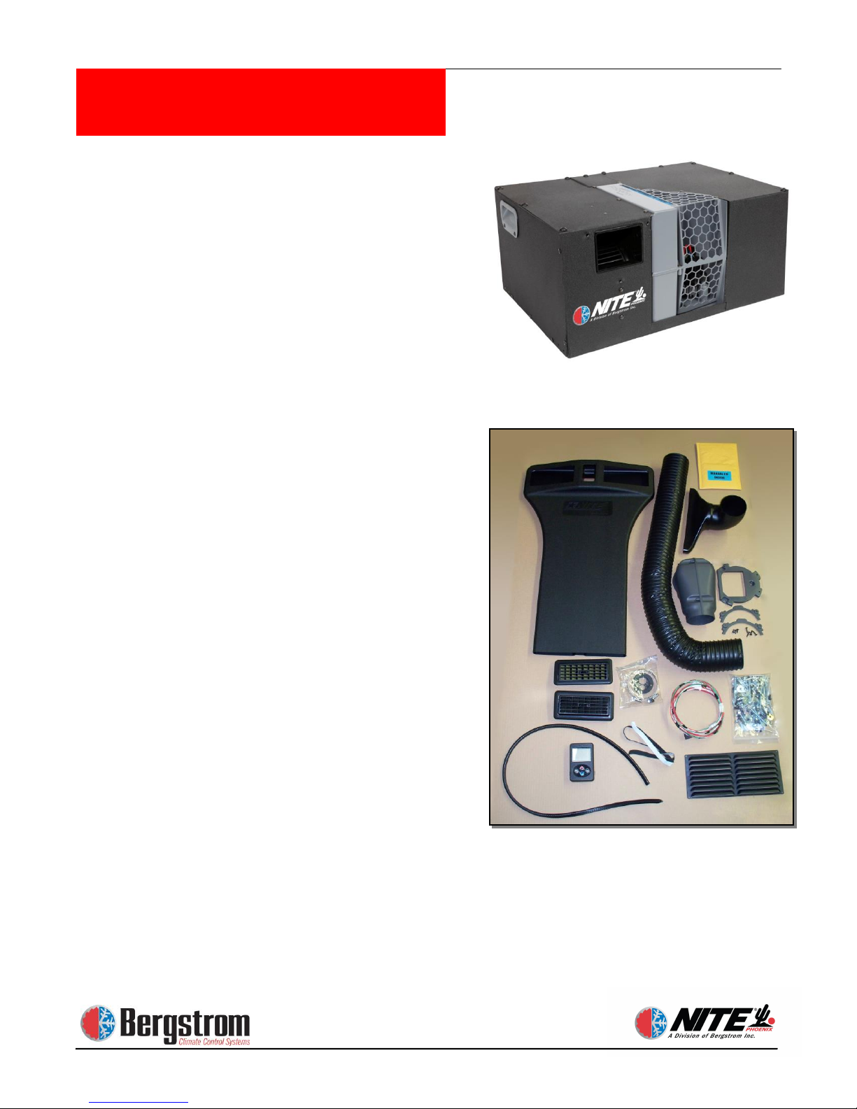
Photo above is representative of kit
1000230792 only.
Page 5

1-5
Kenworth T600-T660-T800-W900 rev 10/7/13
Installation Procedures
Bergstrom Part #
Part Description
Quantity
1000230789 NITE PHOENIX AC ONLY
1000386342
NITE UNIT
1
1000342516
PHOENIX POWER KIT*
1
1000007552
NITE WARRANTY POLICY
1
1000251583
OPERATION CARD
1
585511
NITE WARRANTY CARD/SURVEY
1
1000230787 NITE PHOENIX AC/HEAT - ESPAR
1000386342
NITE UNIT
1
1000038693
ESPAR HEATER KIT**
1
1000342516
PHOENIX POWER KIT*
1
1000007552
NITE WARRANTY POLICY
1
1000251583
OPERATION CARD
1
585511
NITE WARRANTY CARD/SURVEY
1
1000342523 NITE PHOENIX AC/HEAT-WEBASTO
1000386342
NITE UNIT
1
Not sold separately
WEBASTO HEATER KIT
1
1000342516
PHOENIX POWER KIT*
1
1000007552
NITE WARRANTY POLICY
1
1000251583
OPERATION CARD
1
585511
NITE WARRANTY CARD/SURVEY
1
1000230792 INSTALLATION KIT
B290303
CLAMP, HOSE 4.12 I.D.
2
B300571
EDGING BULK
4 FT
B360692
GROMET-NO6 AND NO10 HOSE ADPTR
1
500105
LOUVER, CARY 633 WITH 631 BEZEL
2
500198
GRILLE, AIR RETURN
1
560235
HOSE, DEFROST 4 X 45 INCHES
1
584510
PLUG BUTTON .5 IN HLE 3L4566
2
1000007617
DUCT, STEALTH
1
1000168631
COLLAR, DUCT
2
1000183274
BRACKET, UNIT MNT
4
1000184211
DUCT, UPPER, PHOENIX
1
1000185196
COLLAR, SIDE
1
1000186017
DUCT, ASSY
1
1000218364
DUCT, INTAKE
1
1000219677
DUCT, INTAKE
1
1000224619
GASKET, STRIP
2
1000230622
BRACKET, INTAKE SIDE
1
1000230630
BRACKET, INTAKE SIDE
1
1000251573
CD, INSTALLATION MANUALS
1
1000256319
TEMPLATE, PHOENIX CONTROLS
1
1000415466
TEMPLATE, RECIRC GRILLE
1
1000513102
TEMPLATE, FLOOR
1
1000230794 NITE PHOENIX STD HARDWARE KIT
B203305
NUT, 1/4-20 W/EXT. LOCK WASHER
14
509700
WASHER, .25IN FLAT FS 4B4276
18
600047
SCREW, M6 X 20 MM HEX HD 8T4138
20
600059
SCREW, M6X16MMTORXHD .9X2044
10
600129
SCREW, NO 10 TH 8-15 X .437
5
Page 6

1-6
Kenworth T600-T660-T800-W900 rev 10/7/13
Installation Procedures
1000230794 KIT, NITE PHOENIX STD HARDWARE (cont)
600159
SCREW, NO 12-16 X 1 INCH HI-LO
20
600187
PLASTITE NO8-16 C.75 IN TORX
10
600282
BOLTCARRIAGE .25-20 X 3 IN
10
600283
SCREW, SELF DRILL
52
605007
WASHER, .25 IN HARD FLAT 6V7646
20
620001
POP RIVET, .125 IN 0 9N1995
6
620002
POP RIVET, .812 IN DIA FS
2
620011
POP RIVET, .812 IN DIA FS
6
621820
SCREW, TRUSS HD NO 10 SLF TP FS
24
1000173097
SCREW, 1/4-20 X 1'' HX HS SS
4
1000214538
SCREW, #10 1/2 SELF TAPPING
12
911-C059
SCREW,10-32 X ¾ RND HD SLOT
8
912-C006
WASHER, FLAT #10 SS
4
912-C007
WASHER, LOCK #10 SS
8
1000342516 NITE PHOENIX POWER KIT
*included in kits 1000230789, 1000230787, 1000342523
B223109
FUSE HOLDER
1
B360113
TIE-PLASTIC
50
600283
SCREW, SELF DRILL
2
650119
TERMINAL,INS. MALE BLADE
3
651462
TUBING HEAT SHRINK
22
660706
ASSY,WIRE,BATT.CABLE 5300MMBL
2
660707
ASSY,WIRE,BATT.CABLE 5000MMRE
3
670136
TERMINAL RING 5/16 4 GA
2
670137
TERMINAL RING 3/8 4 GA
20
1000049325
ENCLOSURE, ELECTRICAL
1
1000173480
HARNESS, DAYCAB POWER 4 GA
1
1000174251
FUSE, MEGA 100A YELLOW
1
1000174286
FUSEHOLDER, MEGA BOLT-ON
1
1000230085
FUSE, 5A ATO
1
1000235371
WIRE LOOM .413 ID X 140 FT
1
1000247777
TERM, 3/8" RING 14-16GA SEALE
1
1000247778
TERM, 3/8" RING 18-22GA SEALE
1
1000247779
BUTT CONN, STEP 14-16 TO 18-2
1
1000282660
POWER RELAY, BI-STABLE 300A
1
1000295771
WIRE HARNESS, NITE PHOENIX
1
1000299202
KIT, NITE PHOENIX CONTROLS
1
1000309203
KIT, CONN DEUTSCH DTM04-6P
1
1000309205
TERMINAL, LUG 4AWG 90-DEG
2
1000376501
BATTERY MONITOR SYS, NITE
1
1000493450
WIRE HARNESS, PHOENIX CAN BUS
1
Parts List
Page 7
1-7
Kenworth T600-T660-T800-W900 rev 10/7/13
Installation Procedures
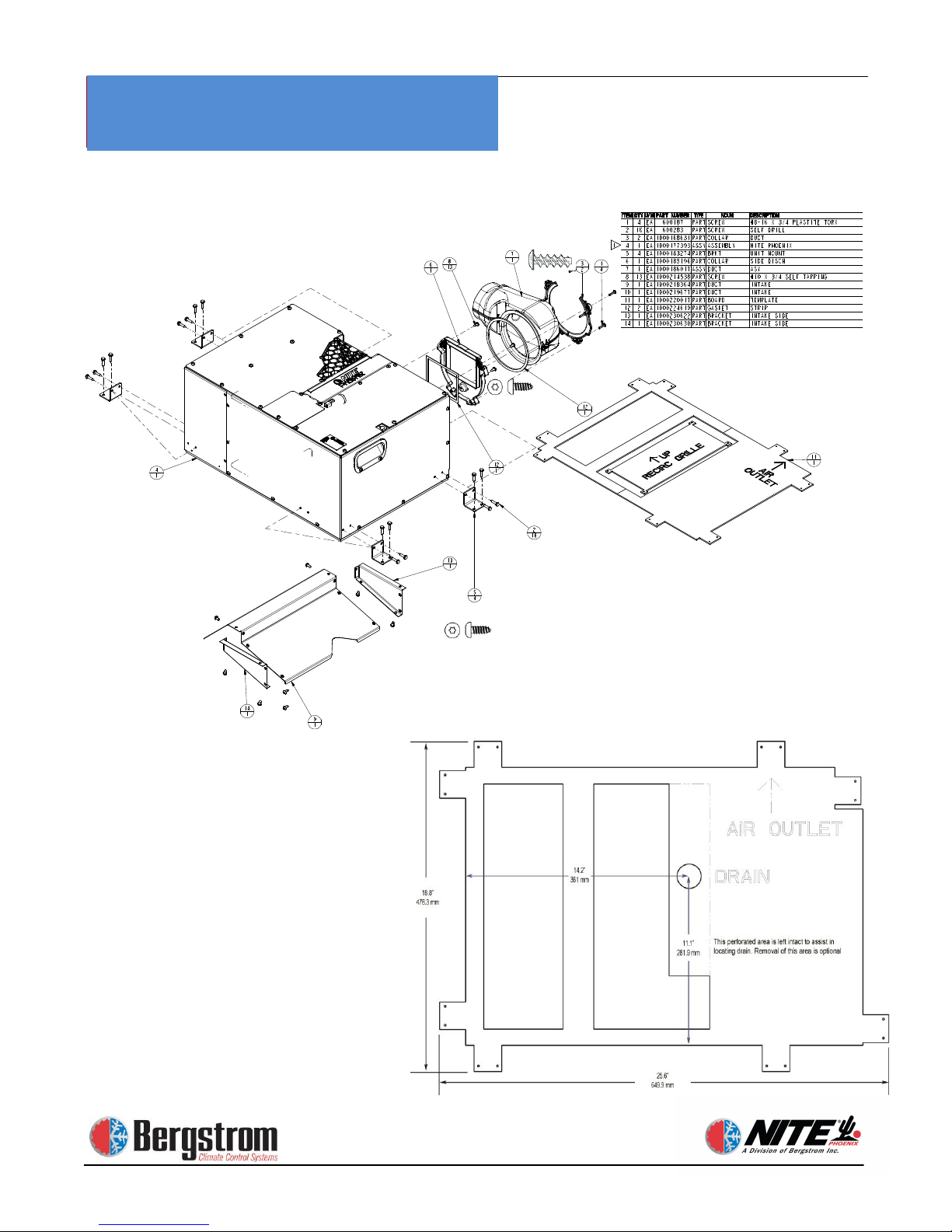
Parts Breakdown
Cardboard Template Layout
Page 8

1-8
Kenworth T600-T660-T800-W900 rev 10/7/13
Installation Procedures
Tools Required
1) Drill Bit Set
2) Hole saws (1″, 1-5/8″, 2″, 2-1/2″, 4-1/2″ and 4-3/4″ )
3) Electric/Air Drill
4) Screwdrivers/Assorted Bits (Flat Head & Phillips Head)
5) Impact Gun
6) Air saw/Jigsaw (Cutting Sheet metal)
7) Torx Head (T20-T25) Bit Set
8) Metric Wrenches
9) SAE Wrenches
10) 1/4″, 3/8″ Drive Ratchets
11) SAE Socket Set
12) Metric Socket Set
13) Wire Cutters
14) Terminal Crimpers
15) Wire Strippers
16) Razor Knife
17) Electrical Tape
18) Cable Cutters
19) #4 Professional Grade Cable Crimpers
20) Cable Strippers
21) Work Light
22) Torque Wrench up to 50 in/lbs
23) U-barrel Crimper
24) Pop Rivet Gun
25) Deutsch Crimpers
Page 9
1-9
Kenworth T600-T660-T800-W900 rev 10/7/13
Installation Procedures
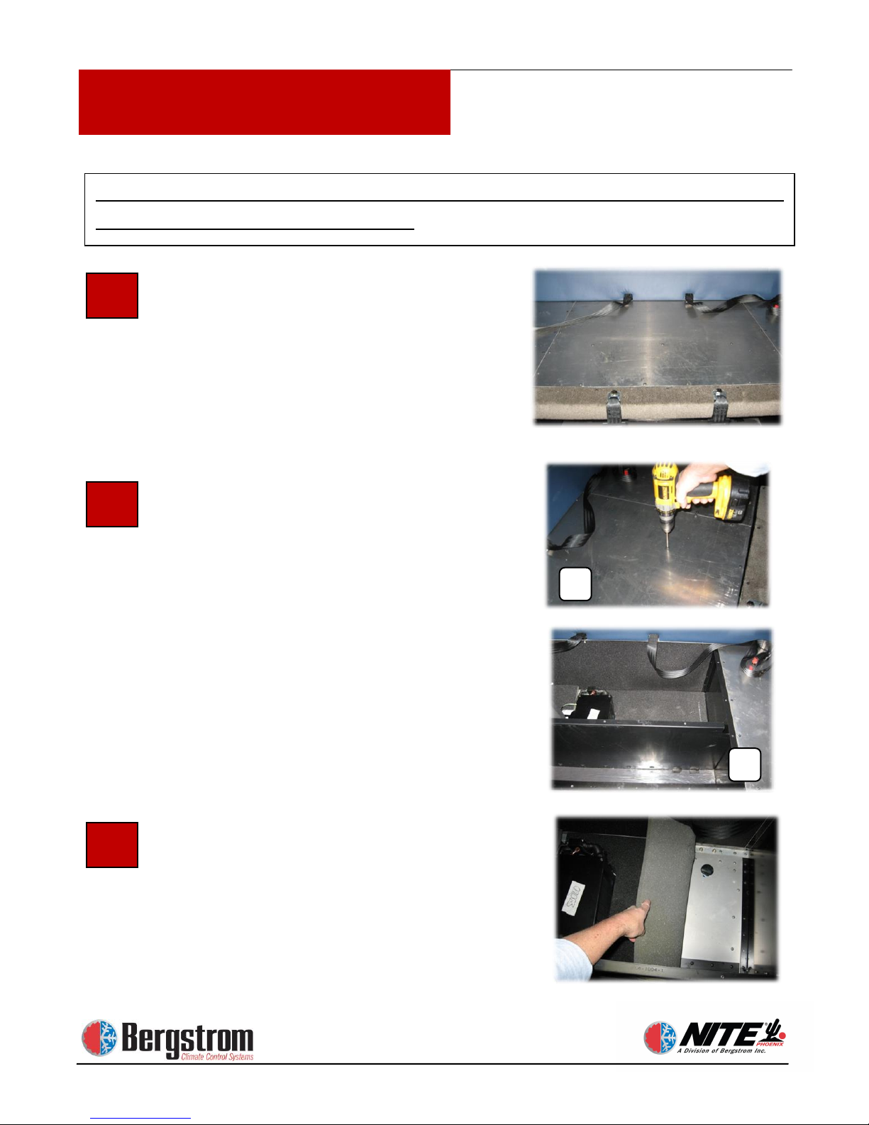
Prepare the Work Area. Start by
disconnecting the ground wire from the
starting batteries. Set up your work
light, clear the sleeper compartment of
loose items, and remove the divider
curtain if there is one. Then remove the
mattress.
Remove Aluminum Bunk Decking
Remove the screws securing the center
panel of the bunk deck (A) exposing the
center storage area (B).
Roll Floor Insulation Back. Pull up
the floor insulation and roll it back out
of your way as shown.
1
3
A
B
Attention: The evaporator blower in the Phoenix will not rotate.
This unit will always be side discharge!
2
Page 10
1-10
Kenworth T600-T660-T800-W900 rev 10/7/13
Installation Procedures
Installation Procedures
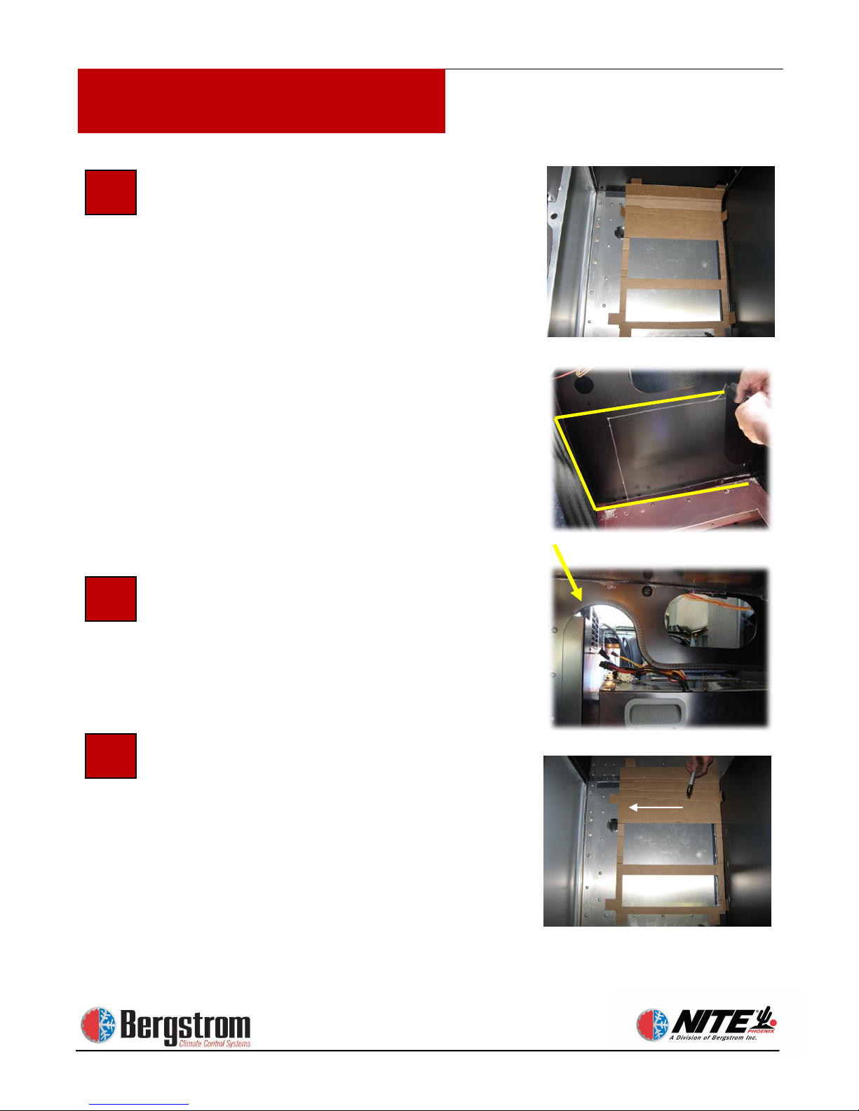
Cut Driver’s Side Support Wall to
Allow Clearance for the NITE
Phoenix Unit.
Mark area as shown to allow proper
clearance around unit for the Phoenix to
protrude inside the driver’s side storage
box. Use an air saw to cut opening.
When necessary cut bottom, front and
rear edges flush. Template must be
placed against the front bunk support
wall to allow clearance for the elbow on
the back of the unit.
Apply Trim Lock Protector to Cut
Edge Cover the sharp edge of the cut
opening.
Determine Location for NITE
Phoenix Unit Mounting Plate. After
the side wall is cut out fold the two
mounting tabs on the template, opposite
the AIR outlet arrow and position the
template close to the front wall of the
bunk support (see photo). Check under
the truck for any obstructions. Locate
the edges of the cross members using
rivets as guides. Do not cut through
cross members.
6
5
4
AIR
Page 11
1-11
Kenworth T600-T660-T800-W900 rev 10/7/13
Installation Procedures
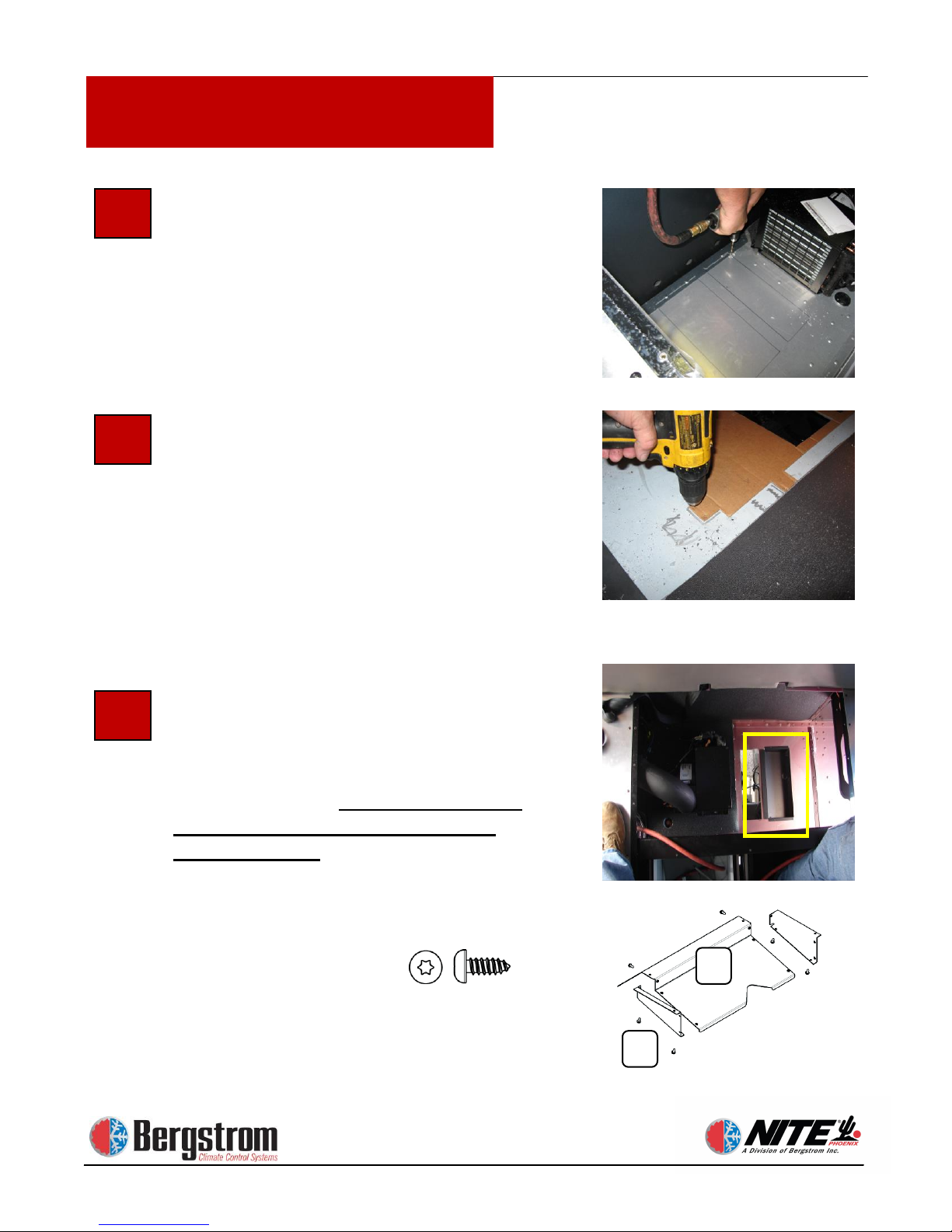
Mark and Cut Holes in Truck Floor
Mark the two rectangular openings in
the template. Drill starter holes in all
four corners of the two areas marked for
cutting. Note location of cross members
prior to drilling holes. Use air
saw/jigsaw to cut through truck floor.
Position the NITE Phoenix mounting
template, as shown, with the condenser
openings over the holes cut in the truck
floor. Mark and drill pilot holes for 4
mounting feet. The unit has 8 possible
locations but you will only use 4. Use
equal spacing to provide adequate
stability of the Phoenix unit.
Pre-assemble the air intake using
#10 X 1/2″ T20 screws (see below).
Place assembled unit in the condenser
hole. Fasten with 1″ screw with 5/16
head self-drilling. Modification of this
assembly may be required to allow
proper air flow. In some applications
the side pieces (A) are not used and (B)
may need to be trimmed to allow proper
air flow.
7 8 9
B
A
Page 12
1-12
Kenworth T600-T660-T800-W900 rev 10/7/13
Installation Procedures
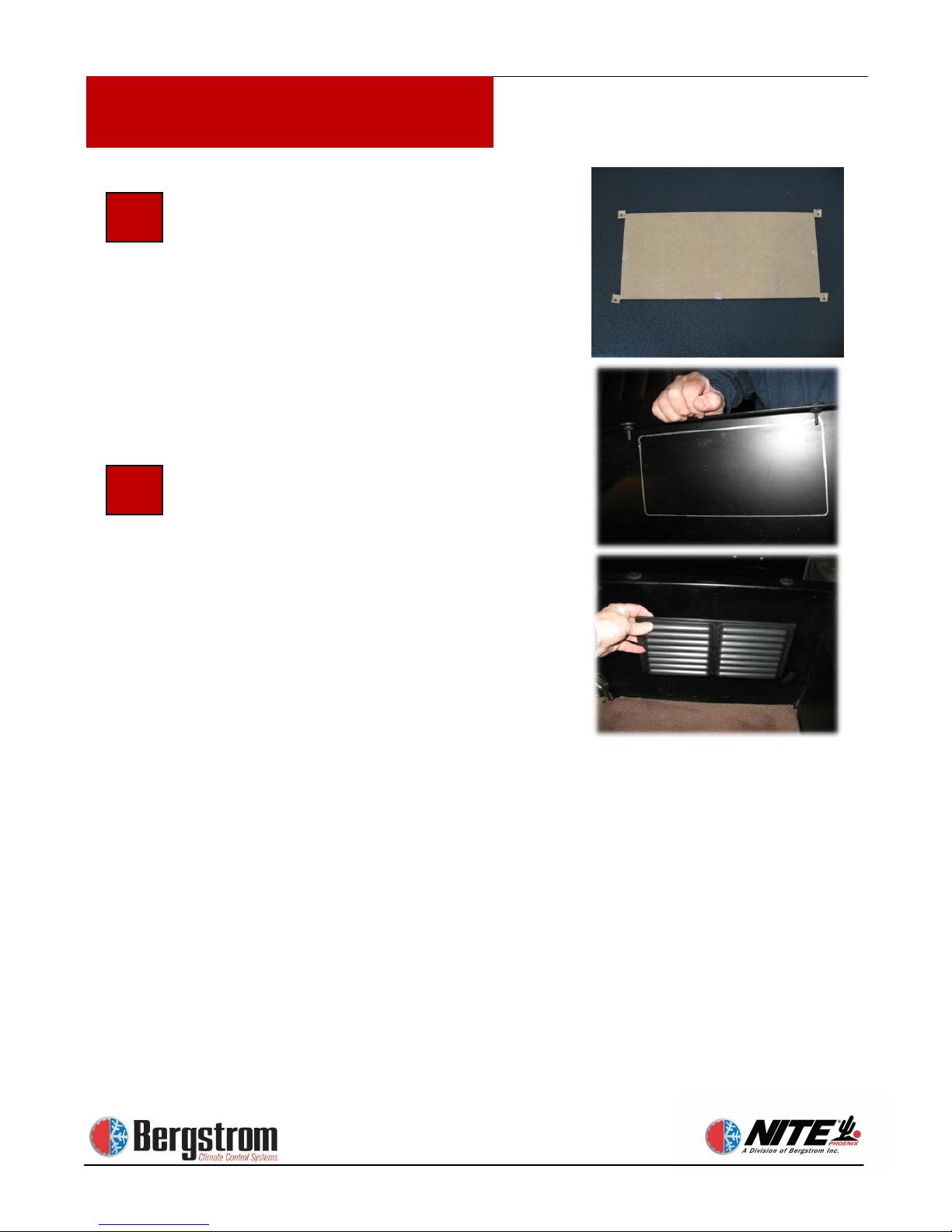
Determine Location for
Recirculation Grill Install the grill in
the center support wall (see photo
showing outline for cutout marked on
center support wall)The opening
should be positioned in front of where
the NITE Phoenix unit will be
positioned. The size should be 11-1/2″
x 4-5/8″. Use provided template for
marking.
Cut Opening for
Recirculation Grill
Cut an opening (A) with a metalcutting air saw or jigsaw for the
recirculation grill in the support wall.
Attach grill (B) to the center wall using
black Phillips head screws.
NOTE: Take precautions not to damage
carpet or upholstery.
10
11
TEMPLATE
Page 13
1-13
Kenworth T600-T660-T800-W900 rev 10/7/13
Installation Procedures
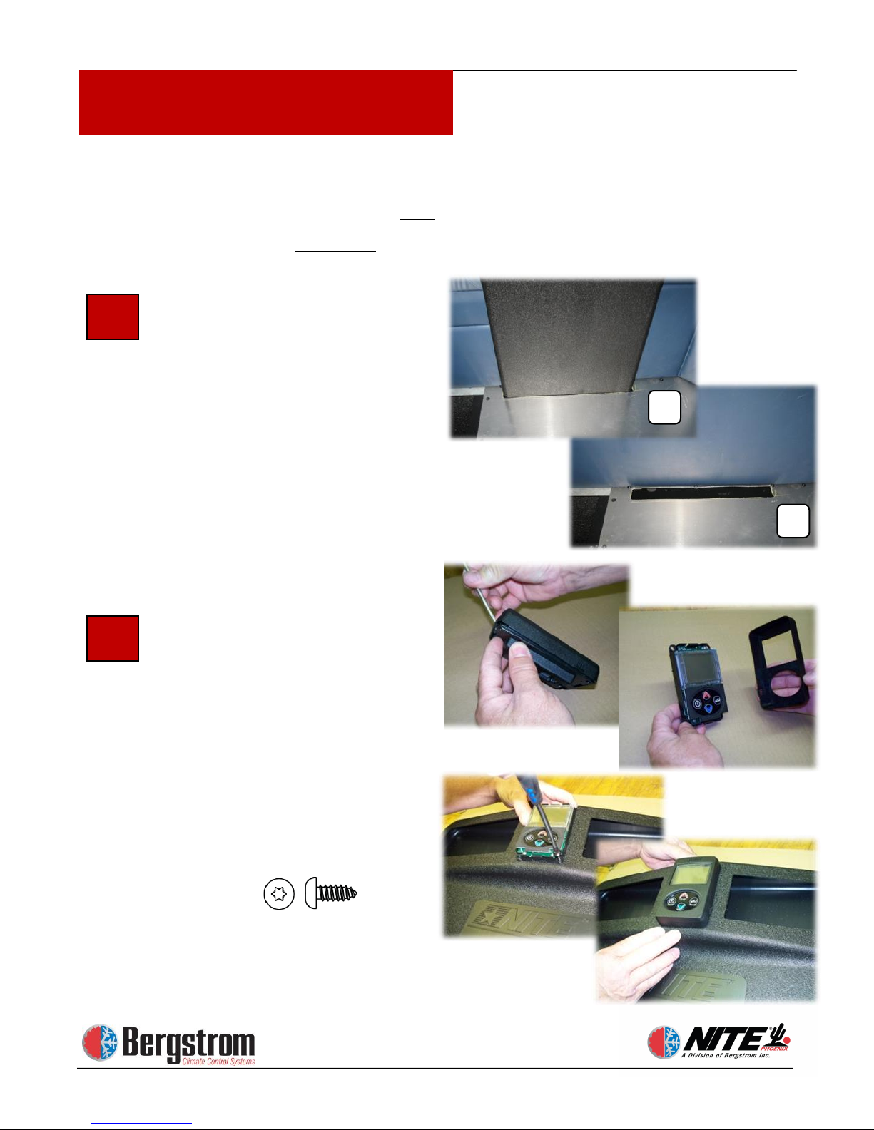
Determine Location for the
NITE Phoenix Duct Next to
Window. Set duct on top of
decking on the driver’s side of
the sleepers back wall. Center
duct between window and corner
seam, mark the aluminum
decking plate around the bottom
of duct (A), remove duct and cut
opening (B).
Attach Control Panel to the
NITE Phoenix Duct. Carefully
depress the lock and remove the
controller cover.
Install the controller to the
duct using #10 x 1/2″ T 20
torque head screw (PN 600129).
Do not over tighten. Replace
cover.
Installation Procedures
12
13
B
A
The following steps vary based on whether the sleeper has a
window or not. If the sleeper has a window, continue with step 12.
If the sleeper does not have a window, proceed to step 24.
Page 14
1-14
Kenworth T600-T660-T800-W900 rev 10/7/13
Installation Procedures
Installation Procedures
15
B
A
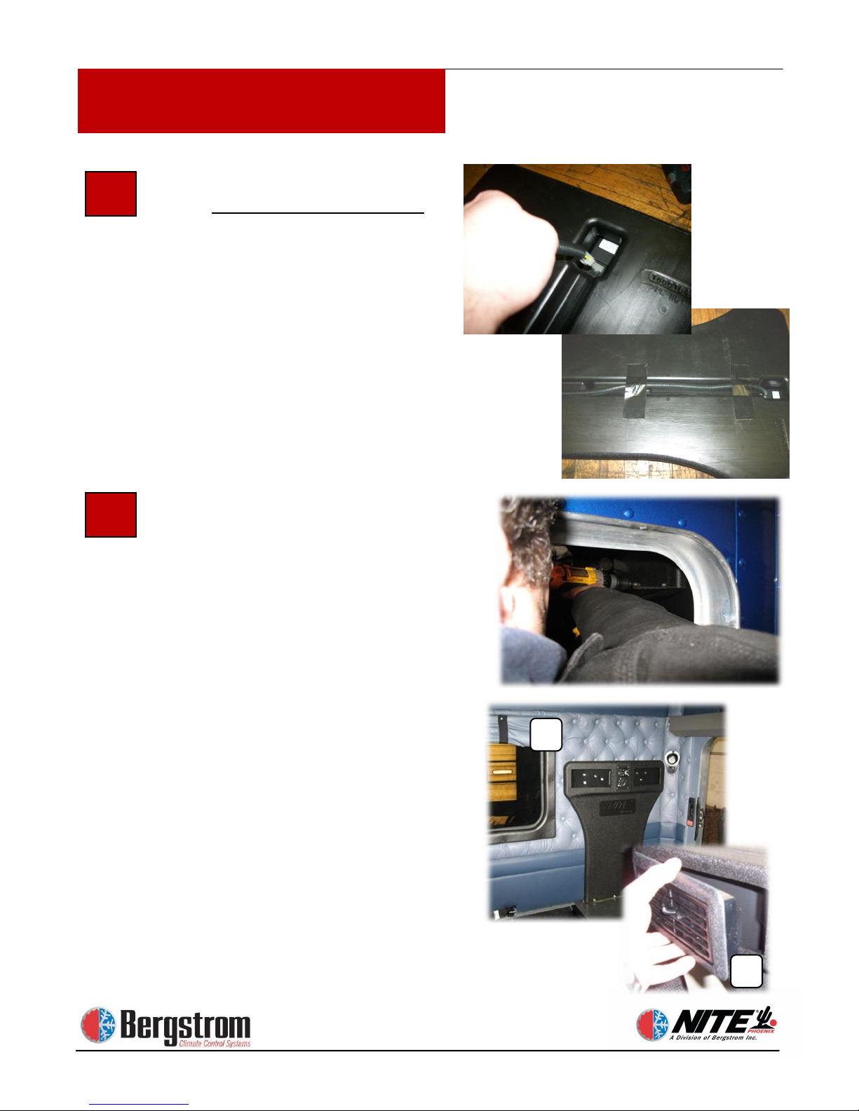
Run Wiring behind NITE Phoenix
Duct. Loom the control harness.
Connect it to the back of the
controller. Place the wiring harness
along the channel on the back of the
duct. Secure wiring in channel with
tape. The duct is now ready to be
attached.
Attach stealth to the NITE Phoenix
Duct. After the controls are installed
slide NITE Phoenix duct and wiring
down through the slot in the decking
enough to fasten the elbow to the duct
using two 1″ X 5/16 self-tapping
screws. Seal around stealth with
silicone sealant. Now raise duct back
up to proper location.
Attach NITE Phoenix Duct to Back
Wall of Sleeper. Press the top of the
duct up against the back wall. Make
sure the duct is square and level
against the back wall. Use 1″ X 5/16
hex head self-tapping screws to attach
top of duct to back wall. Place 3 - 5
screws in each duct opening and install
at different angles (A). Take care not
to over tighten. Snap both louvers into
place (B).
14
Page 15
1-15
Kenworth T600-T660-T800-W900 rev 10/7/13
Installation Procedures
Installation Procedures
17
16
18
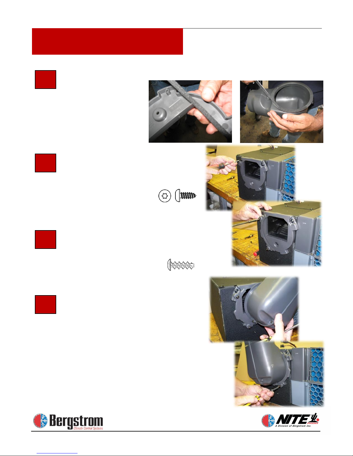
Attach seal strip to duct bracket
and elbow.
Prepare to Install Unit
Install the duct elbow mounting bracket
to the Phoenix unit using #10 X 1/2″
T20 elbow bracket screws.
Now install one half of the elbow
support ring using elbow flange screws
#8 X 3/4″ T20. Do not completely
tighten screws at this time.
Slide the elbow into the support ring and
install the second half.
Once it’s installed you can snug all
screws.
19
Page 16
1-16
Kenworth T600-T660-T800-W900 rev 10/7/13
Installation Procedures
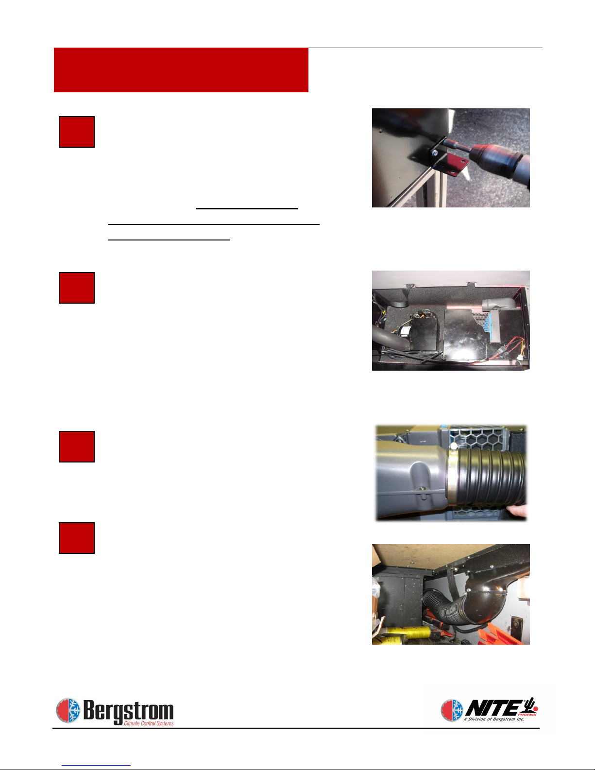
Install mounting feet
The Phoenix unit has 8 pre-dimpled
locations. Fasten feet in the 4 locations
matching the predrilled holes from page
12 step 8. Use 1″ X 5/16 hex head self drilling screws. Do not install feet
where the case is not dimpled or you
will damage the unit.
Test Fit the NITE Phoenix Unit,
Elbow Duct and Flange. Set the NITE
Phoenix unit in place as shown. Test fit
the flange and elbow for clearance
against the rear wall. Rotate the elbow
towards the driver’s side. Now secure
the unit using eight
1″ X 5/16 head self-drilling screws in
the predrilled holes.
Attach Assembled Elbow to the
Flexible Duct. Insert flexible duct onto
the round end of the elbow unit. Tighten
hose clamp to secure flex duct to elbow.
Attach Flexible Duct to Transition
Duct. Run flexible duct through
support wall to the NITE Phoenix duct
location. Attach the flexible duct to the
transition duct. Tighten hose clamp to
secure flex duct to transition duct.
Apply silicone sealant around seam.
Photo shows stealth cut and rotated 90°.
Go to step 37
20
21
22
23
Photo shows truck with rear window application
Page 17
1-17
Kenworth T600-T660-T800-W900 rev 10/7/13
Installation Procedures
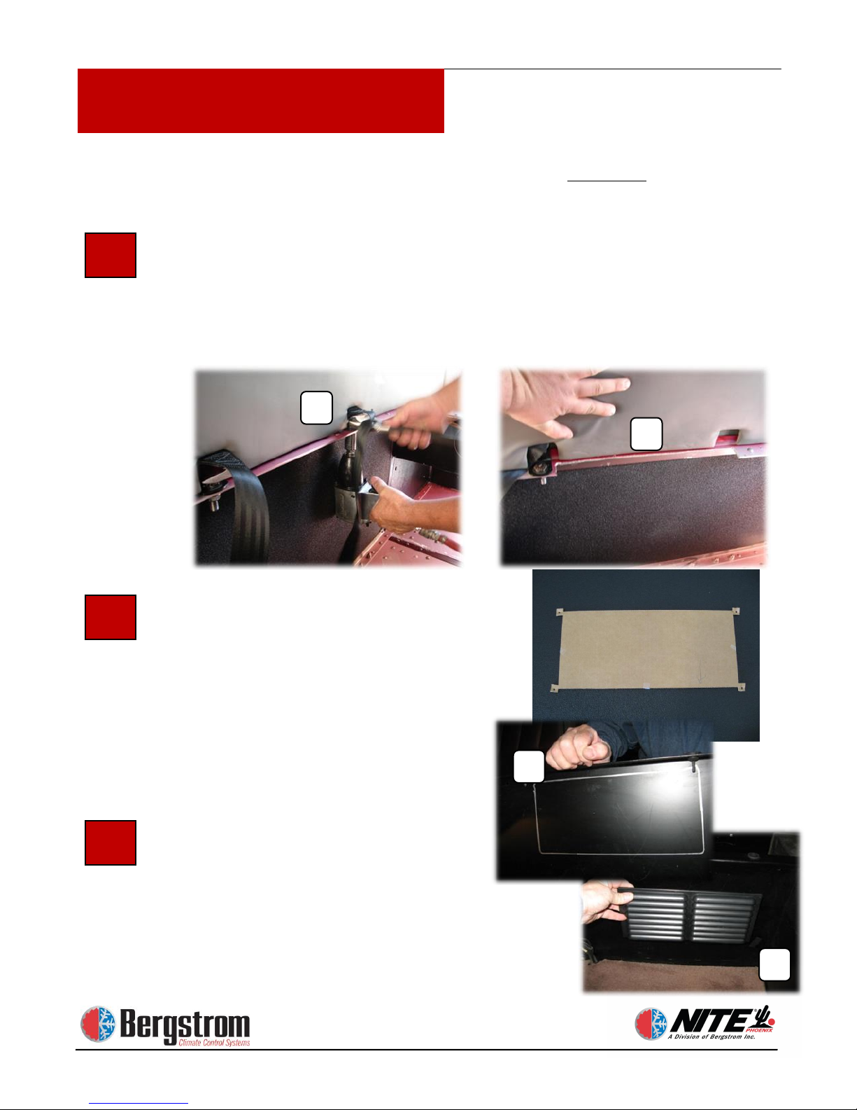
Follow steps 24 thru 36 ONLY if your sleeper does not have a
window. If your sleeper has a window, refer back to step 10.
25
Relocate Seat Belt - Trim Flange to Allow for NITE Phoenix Duct
A clearance cut needs to be made in the aluminum flange on the back wall.
This will allow clearance for the NITE Phoenix duct to be mounted flush on
the back wall. Remove the driver side seat belt (A) and relocate and reattach
it. Trim the aluminum flange between the two seat belt straps a minimum of
13-1/2″ flush against back wall (B).
Determine Location for Recirculation
Grill Install the grill in the center
support wall (see photo showing outline
for cutout marked on center support
wall)The opening should be positioned
in front of where the NITE Phoenix
unit will be positioned. The size should
be 11-1/2″ x 4-5/8″. Use provided
template for marking.
Cut Opening for Recirculation Grill
Cut an opening (C) with a metal-cutting
air saw or jigsaw for the recirculation
grill in the support wall. Attach grill (D)
to the center wall using black Phillips
head screws.
NOTE: Take precautions not to damage
carpet or upholstery.
24
B
A
26
TEMPLATE
C
D
Page 18
1-18
Kenworth T600-T660-T800-W900 rev 10/7/13
Installation Procedures
Installation Procedures
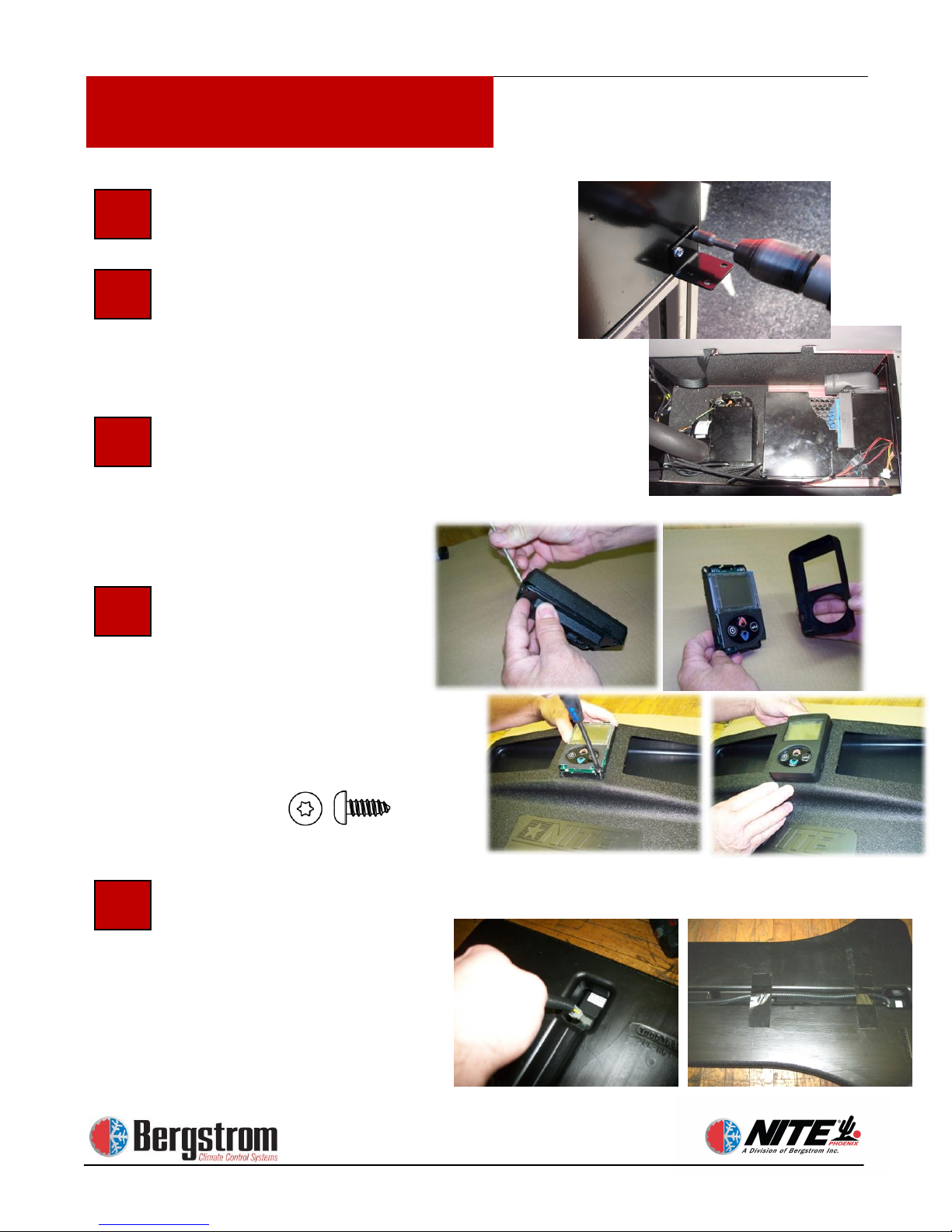
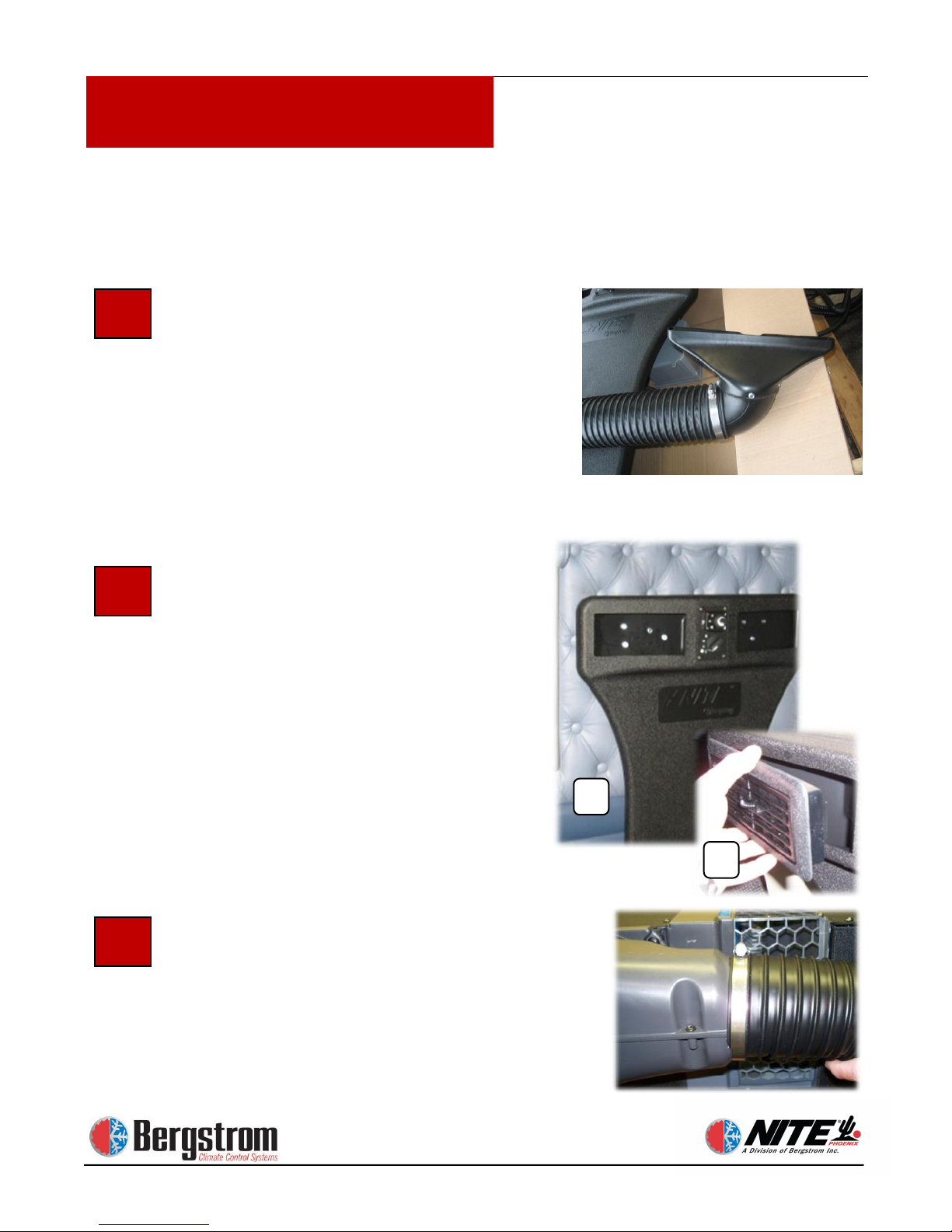
Preassemble Elbow (see page 1-15)
Install mounting feet. See page 1-16
step 20. Test Fit the NITE Phoenix
Unit, Elbow Duct and Flange. Set the
NITE Phoenix unit in place as shown.
Install unit. Now secure the unit using
eight 1″ X 5/16 head self-drilling
screws in the pre-drilled holes drilled in
step 8 page 1-11.
Attach Control Panel to
NITE Duct. Carefully
depress the lock and
remove the controller cover.
Install the controller to the duct
using #10 x 1/2″ T 20 torque head
screws (PN 600129). Do not over
tighten.
Run Wiring behind NITE Duct.
Loom the control harness.
Connect it to the back of the
controller. Place the wiring
harness along the channel on
the back of the duct. Secure
wiring in channel with tape.
28
29
30
27
31
Page 19
1-19
Kenworth T600-T660-T800-W900 rev 10/7/13
Installation Procedures
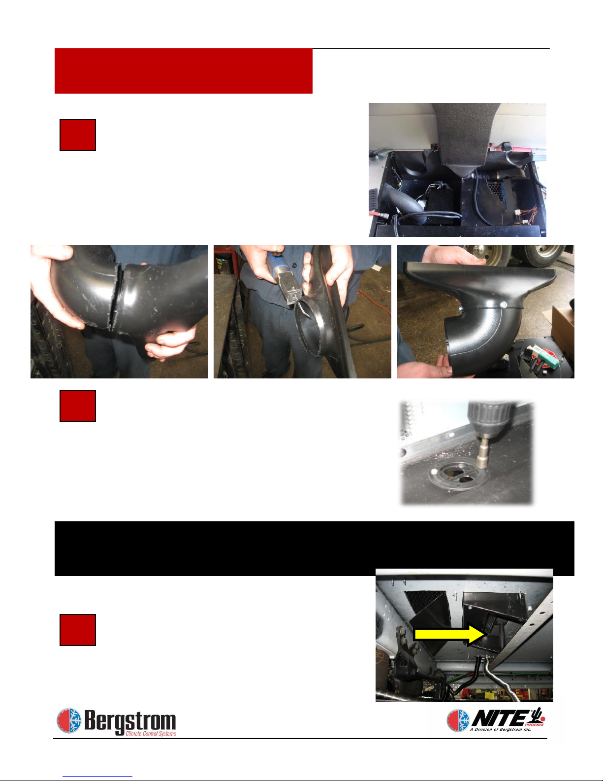
33
Attach Stealth to the NITE Duct.
After the controls are installed and the
stealth is cut and rotated 90° fasten the
stealth to the NITE Phoenix duct using
four 1″ X 5/16 self-tapping screws.
Apply silicone sealant around seam.
Duct shown has been cut and rotated 90
degrees. See instructions page 1-22.
NOTE: Silicone sealant is not included
in kit.
Attach NITE Phoenix Duct to Back
Wall of Sleeper. Press the top of the
duct up against the back wall. Make
sure the duct is square and level against
the back wall. Use 1″ X 5/16 hex head
self-tapping screws to attach top of duct
to back wall. Place 3 - 5 screws in each
duct opening and install at different
angles (A). Take care not to over
tighten. Snap both louvers into place
(B).
Attach Flex Hose to Stealth and
Elbow. Secure with 4″ clamps.
32
34
B
A
Cutting and rotating the Stealth elbow (before installing the stealth
adapter see pg 1-22 for instructions)
Page 20
1-20
Kenworth T600-T660-T800-W900 rev 10/7/13
Installation Procedures
Transition duct is designed to be
separated by cutting at the bevels.
Removing this flare will allow the 90
degree elbow to slide inside the stealth
providing 360 degrees of rotation.
Secure with self-drilling screws.
Install the NITE Phoenix Unit Power
Harness Grommet. Chose a good
location for the flanged grommet
provided. Drill a 2″ hole and install
provided grommet in the floor. Route
all Phoenix and heater cables through
this grommet. Secure harness with
provided zip ties.
Install Drip Tube Under Truck.
Notice deflector pan has be modified to
allow proper air flow
35
36
37
Failure to use the proper cable loom and/or grommet will result in damage to cables, unit and/or
vehicle. Always seal all open areas in grommet with silicone when installation is complete.
Silicone is not provided in kit.
Page 21

Rev 9/25/2013
Section 2
Electrical Installation
Page 22
2-1
Electrical Installation
2
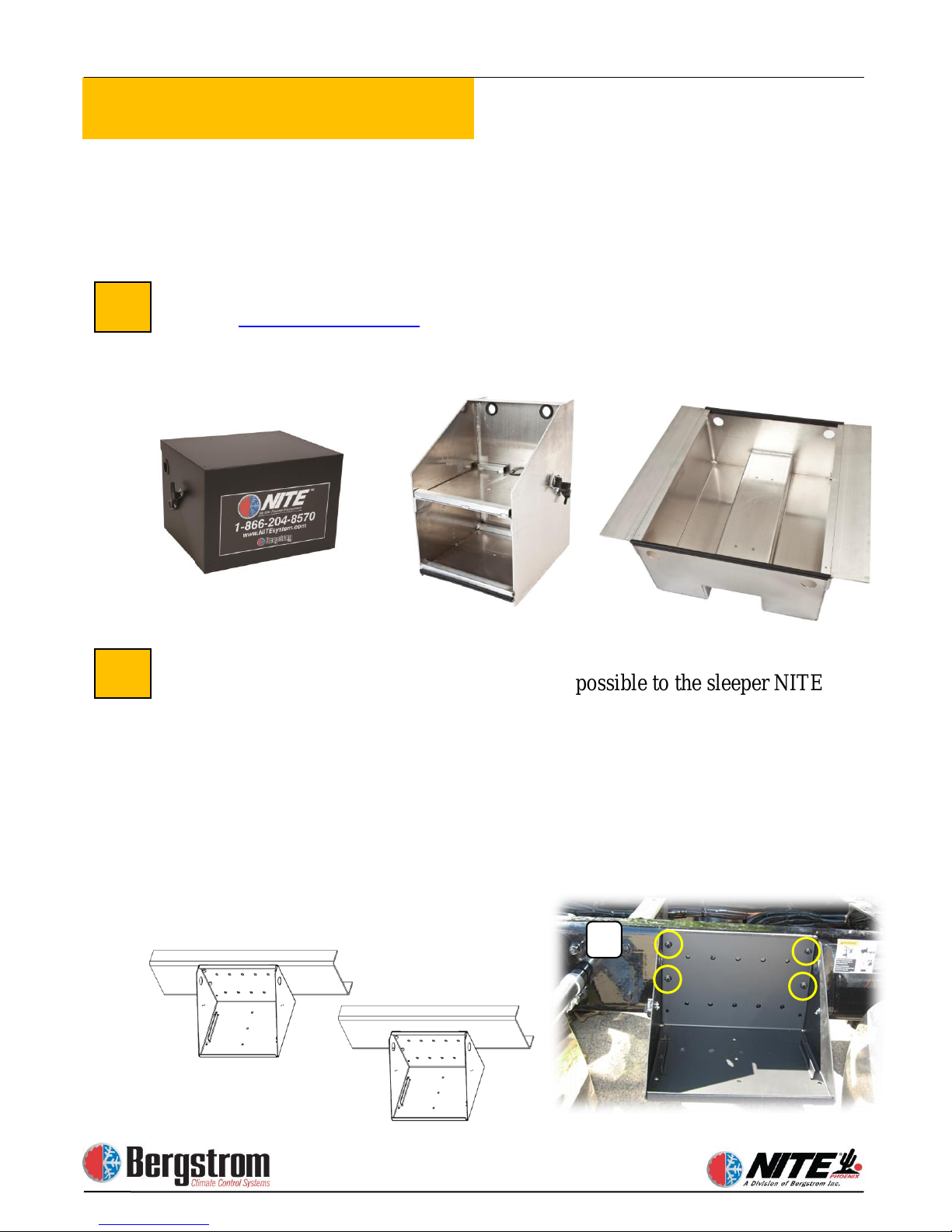
NOTE: Bergstrom does not condone putting batteries under the sleeper bunk. The floor is not
designed to carry that amount of weight and even deep cycle AGM batteries can emit gas under
certain circumstances. Bergstrom can only support batteries being placed in battery boxes or tool
Steel Battery Box Installation
Locate the battery box on the frame as close as possible to the sleeper NITE
Phoenix unit. When positioning the box, always keep the top of the box as
close to the top of the frame rail as possible – Some manufacturers recommend
no drilling within 2″ of top or bottom of frame rail. Check truck manufacturer
guidelines prior to drilling.
of 4 holes. Always use the holes in the rear outer corner area where you have
double walled steel. Of the 3 holes available on each side of the outer most
edge of box, choose the top and center holes on each side (see photo A). Drill
frame rail using ½″ HS bit. Install box with ½″ grade 8 bolts and hardware
provided. Tighten securely.
1
A
Correct
Incorrect
Available Battery Boxes Options
Refer to
for styles and part numbers. Aluminum clamp-on
boxes include between rail and vertical box styles. Steel battery boxes require
frame drilling and must be attached to frame rail with bolts (see instructions in the
following steps 2 and 3).
Vertical
Between Rail
Steel Battery Box
boxes designed to support the weight of the batteries outside the cab of the truck.
www.nitesystem.com
(2 required)
Clamp-On Box
Clamp-On Box
Using box as template, mark and drill a minimum
Page 23
2-2
Electrical Installation
3
5
4
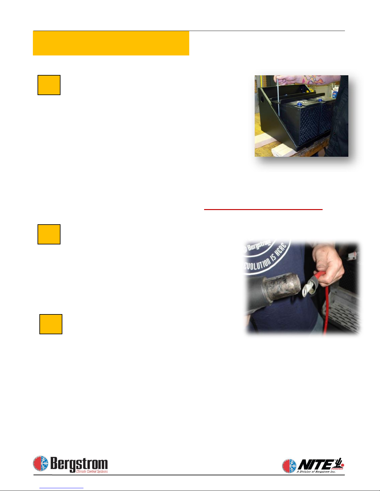
Attaching Hold-down Brackets
Set two batteries side-by-side in the
battery box and place a hold-down
bracket on top, with the u-channel
facing up. Take two 5/16″ bolts, place
a 5/16″ flat washer on each, and then
put the bolts through the outer holes.
Tighten each bolt securely from under-
neath using the supplied nuts and
washers. Repeat the procedure for the
other two batteries.
Preparing Cables
The batteries are wired series/parallel
for 6 volt or parallel only for 12 volt.
See diagrams on pages 2-3 and 2-4
Make and Install All Cables described
in steps 6a or 6b depending on which
batteries you are using.
NOTE: Before performing any wiring, Disconnect Truck Batteries.
Page 24
2-3
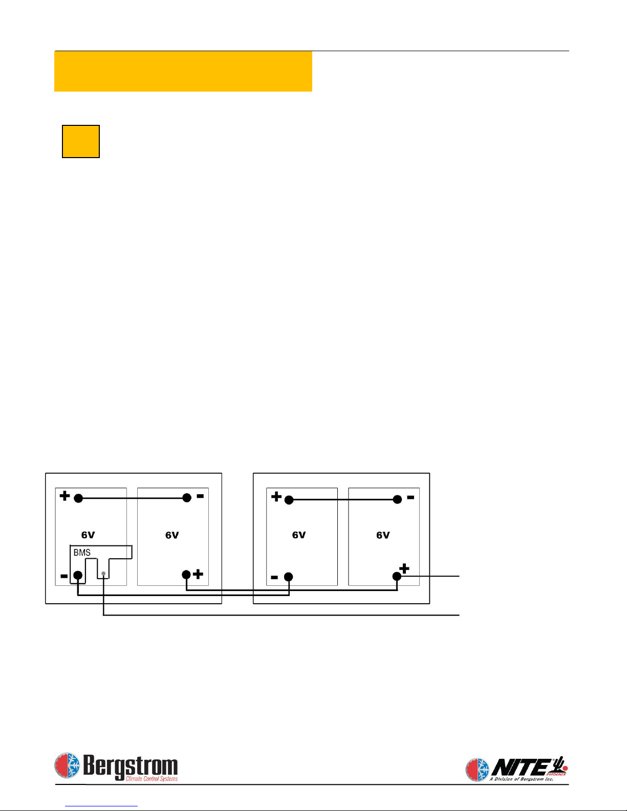
Electrical Installation
Step 1: Make and install the two short
battery cables. These cables connect
the positive (+) of one battery to the
negative (-) of the other to create a set
or bank. We refer to this as a series
connection. See drawing below.
NOT connect any other cables or
wires to these terminals.
Step2: For the positive to positive
parallel connections, measure and cut
a piece of red cable to the proper
length. Attach a ring terminal to each
end using a professional grade
crimper. Place heat shrink around each
6a
terminal and heat. Then loom it. Use
this cable to connect the positive (+) of
one bank of batteries to the positive
(+) of the other bank of batteries.
Step3: Repeat procedure for the
negative to negative connection using
a black cable. Then loom it. Use this
black cable to connect the
negative (-) of one bank of batteries to
the negative of the other bank of
batteries.
Do NOT use truck frame as a ground
Directions for Wiring A 6-Volt Series/Parallel,
4 Battery NITE Phoenix
Connect positives here: AC
=12V
Battery Set
Battery Set
BMS=Battery Management System
DO
Unit, Heater, and Separator
Connect negatives here:
AC Unit, Heater, and Truck
Battery negative
Page 25
2-4
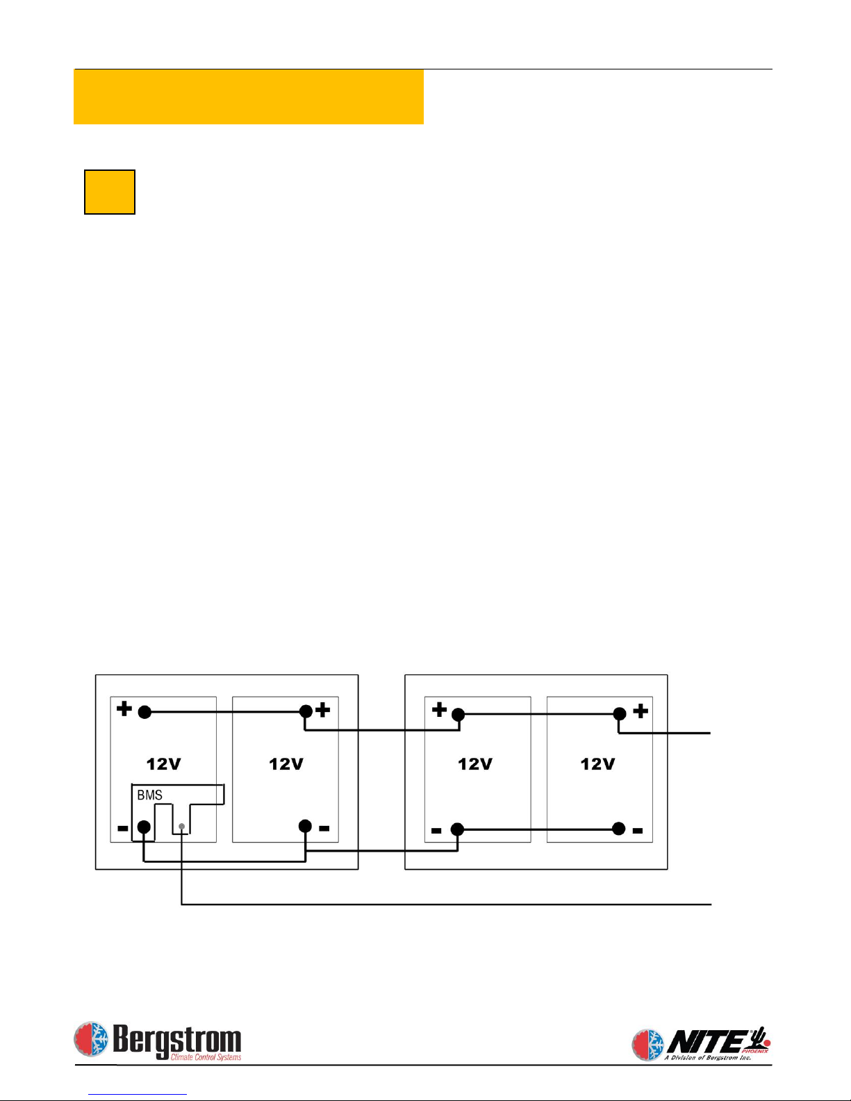
Electrical Installation
Step 1: For the positive (+) to positive
(+) parallel connections measure and
cut pieces of red cable to length. Attach
a ring terminal to each end using a
professional grade crimper. Place heat
shrink around each terminal and heat.
Then loom it. Use these cables to
connect all positive (+) terminals on all
4 NITE Batteries.
Step2: For the negative to negative
connections repeat procedure using
black cables. Then loom it. Connect all
negative (-) terminals of the 4 NITE
Batteries together.
Do NOT use truck frame as a ground
6b
Directions for Wiring A 12-Volt Parallel, 4 Battery NITE Phoenix
Parallel is all positives connected together and all negatives connected
together.
Battery Set
Battery Set
Connect
positives here:
negatives here:
BMS=Battery Management System
AC Unit,
Heater, and
Separator
Connect
AC Unit,
Heater, and
Truck Battery
negative
Page 26
2-5
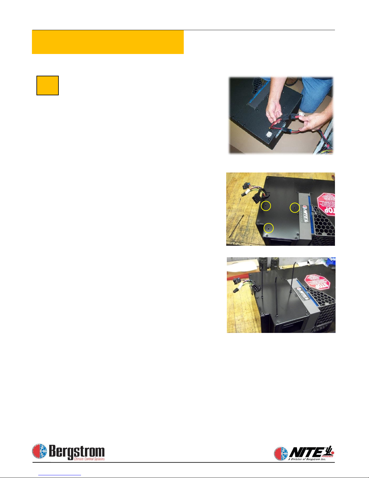
Electrical Installation
Install the NITE Phoenix Power
Harness.
place the protective split plastic loom
around each cable. Route the cables
from the NITE Phoenix unit, down
through the floor grommet and along
the frame rails to the NITE Batteries.
Secure harness at the unit to prevent
stress on harness connectors.
7
Take the power harness and
Page 27
2-6
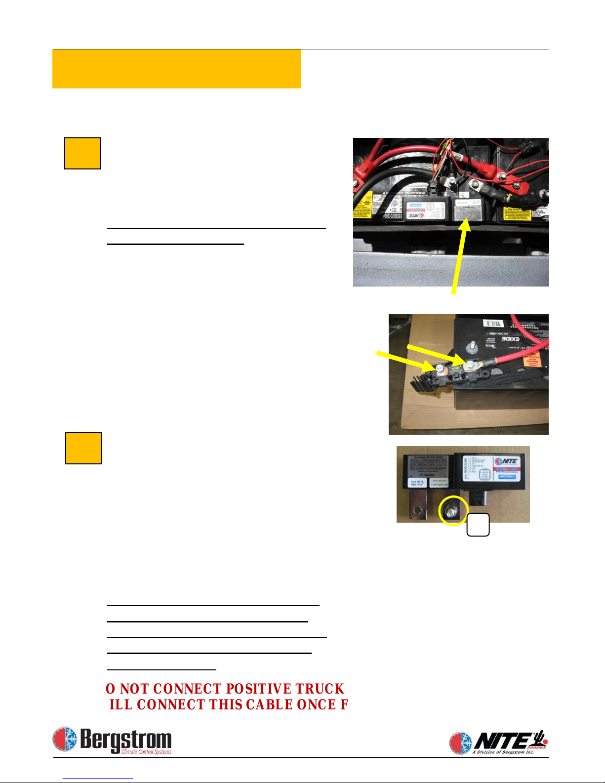
Electrical Installation
8
DO NOT CONNECT POSITIVE TRUCK BATTERY CABLE YET. WE
WILL CONNECT THIS CABLE ONCE FINISHED.
9
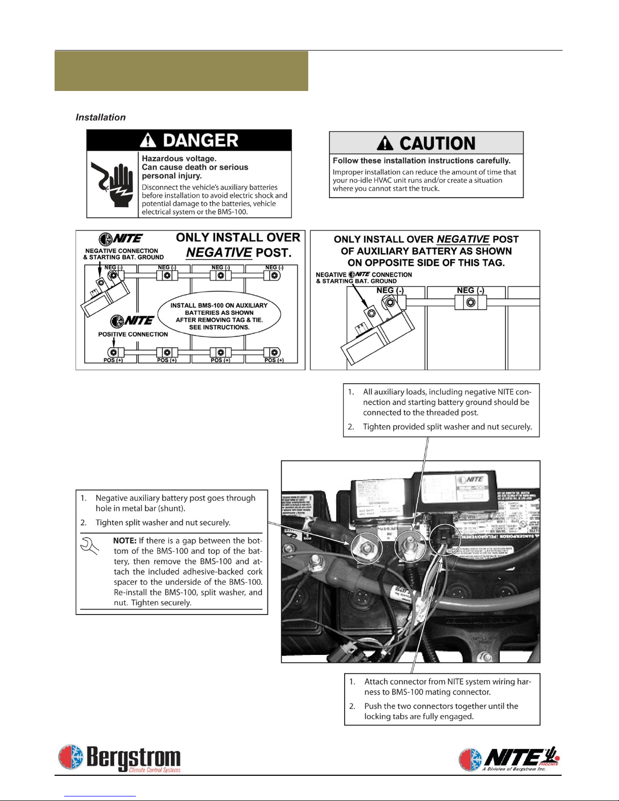
Install Battery Management System
Lug with (open hole) mounts on the
battery negative post. Grounds for the
Phoenix and Aux heater will connect to
the threaded stud post (A-bottom photo)
along with the ground cable from the
truck starting batteries
monitoring amps drawn from the batteries
as well as the charging current to the
batteries. It also controls the separator
solenoid.
Connect Power Cables from Phoenix
Unit to the
positive cable from the NITE Phoenix unit
to the 100 amp mega fuse in the fuse
holder. Kit contains 2 lugs with 5/16
diameter holes. Make a short (jumper)
battery cable to go from the fuse to the
Aux battery positive terminal of the NITE
Batteries. Trim end of lug if necessary to
prevent damage to fuse.
Connect the negative cable from the
NITE Phoenix
threaded stud (A) (see photo at right)
on the BMS. Also see diagrams on
pages 2-3 and 2-4.
Battery Management System Installed
5/16 lugs
NITE Batteries. Connect
unit to the negative
. This device is
Page 28
2-7
Electrical Installation
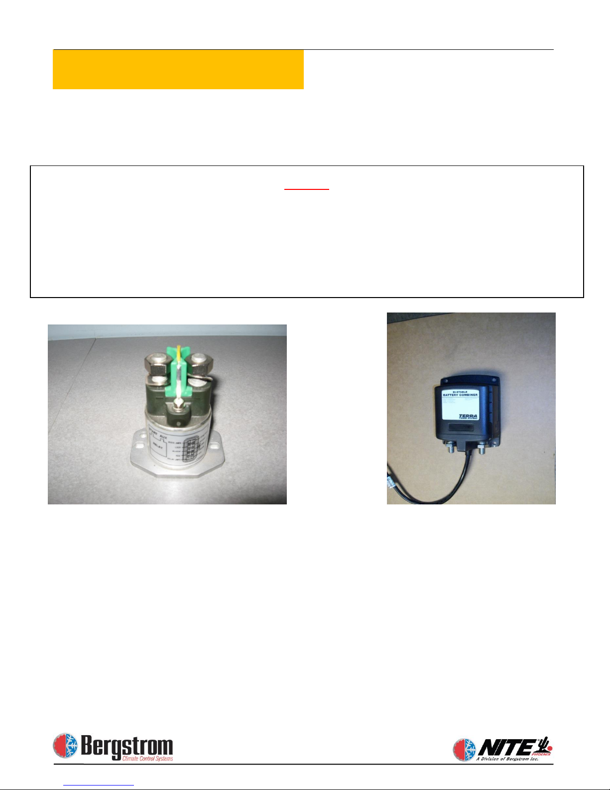
STOP!
SEPARATOR
TERRA POWER
KISSLING
PROCEED TO PAGE 2-10, STEPS 20-41 FOR THE TERRA POWER
FOLLOW STEPS 10-19 FOR KISSLING SEPARATOR
Page 29
2-8
Electrical Installation
11
Mounting the Separator Enclosure
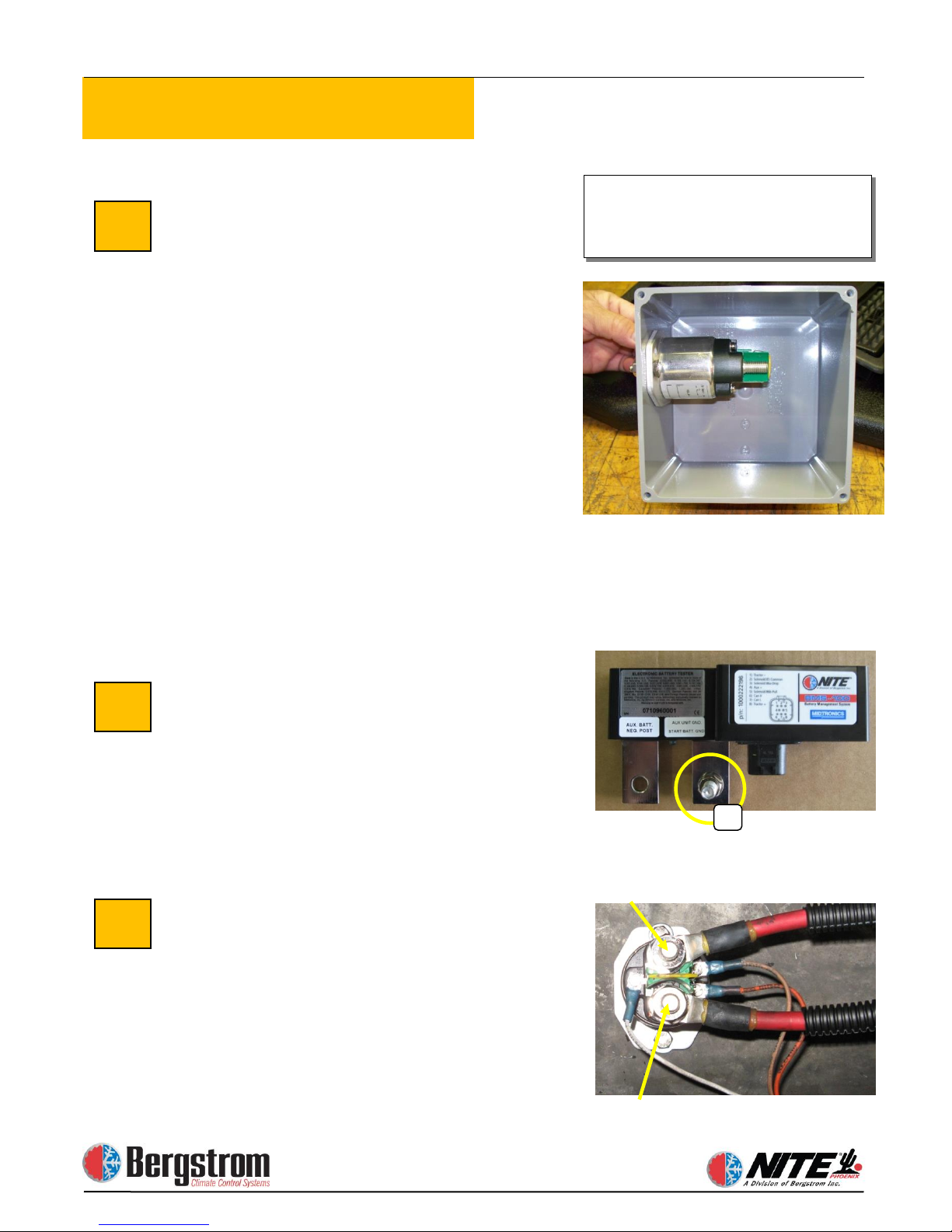
The battery separator can be located in a
battery box or in the supplied protected
enclosure. Mark and drill two ¼″ holes
through the back of the plastic box and
the support it will be mounted to. Before
permanently attaching the separator
enclosure, prepare and mount the
separator in the box. The separator will
mount to the side of the box with 2 ¼″
bolts and hardware. Drill large holes in
the bottom of the box and route the cables
through the holes to the separator.
Securely fasten the separator and box
using the provided ¼″ bolts, washers and
lock nuts.
Run Cables from Truck Batteries
Loom 2 full length battery cables, 1 red
and 1 black. The red (pos) cable will
connect the truck starting batteries
positive post to the (start) post #88 of the
battery separator. The black (neg) will
connect the truck (neg) to the threaded
stud (A) of the BMS(see photo).
Connect
Separator.
measure and cut to proper length. Crimp
ring terminals and heat shrink. Connect
one end to the appropriate positive (+)
terminal of the NITE Batteries. See
diagrams on pages 2-3 and 2-4. Connect
the other end to the AUX terminal # 88a
of the battery separator.
Threaded Stud
Disregard the enclosure
separator inside the battery box.
10
88A
88
12
Note: The separator ties to the truck’s
starting batteries and allows charging priority to the
starting batteries. The NITE Batteries begin
charging after the starting batteries reach 13.2 volts.
instructions if you mount the
NITE Batteries to Battery
Using red battery cable,
Page 30
2-9
Electrical Installation
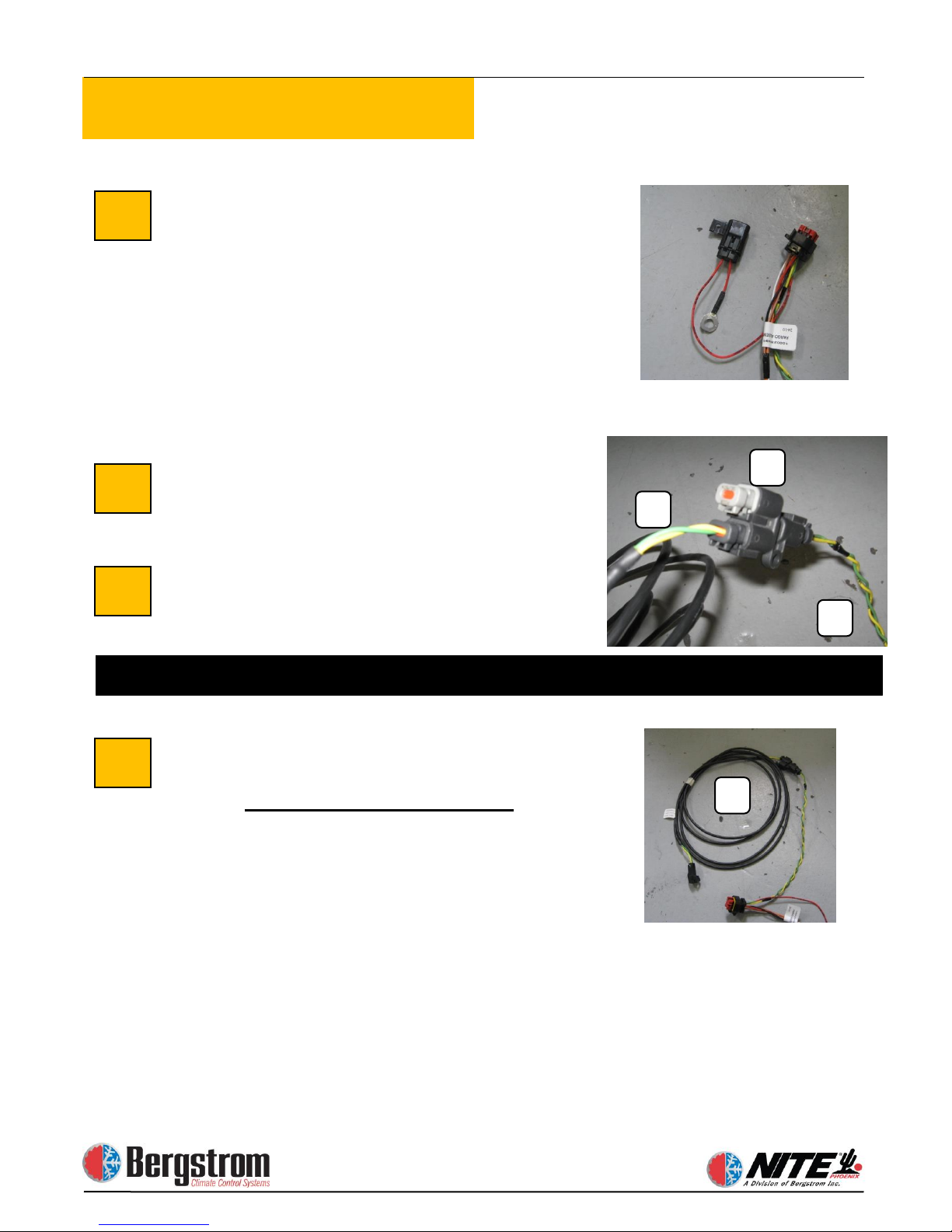
Battery Management System Wiring
Harness.
BMS. Auxiliary battery power wire with
fuse connects to battery pos on the aux.
batteries. This harness splits three ways:
Red/black goes to truck starting batteries,
orange/tan/white go to separator,
green/yellow go to can bus on Phoenix
unit inside the truck. All three must be
loomed.
Install Y connector at BMS connection
(A) - wires green and yellow
Install resistor plug (B) into Y
connector
Connect Can Bus harness from the
Battery Management System wiring
harness.
(C). Route this harness inside the truck
through the floor grommet and connect at
the Phoenix unit.
13
C
15
C B A
16
14
Systems built after 9/1/2013 do not use a Y connector and resistor
8 pin connector plugs into the
This harness must be loomed
Page 31
2-10
Electrical Installation
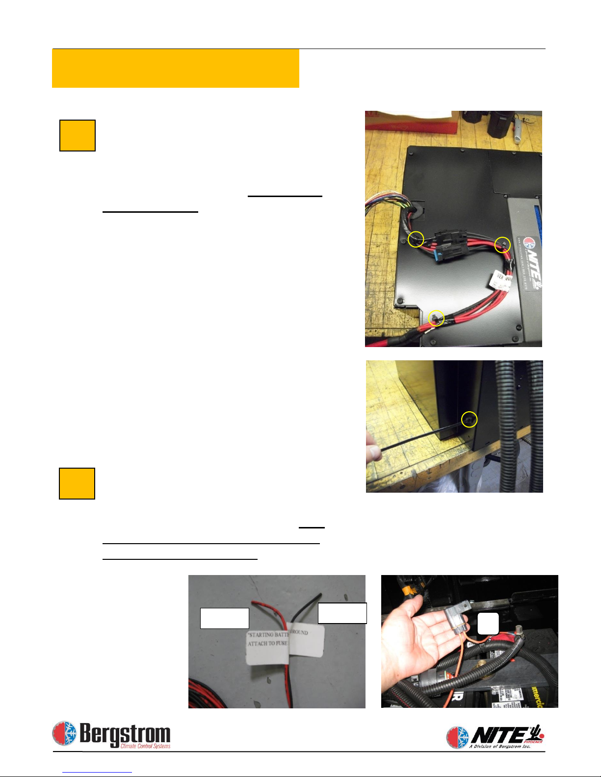
Connect Battery Management System
to Start Batteries. 2 wire harness from 8
pin connector. This harness routes from
the BMS in the Aux battery box to the
truck starting battery box.
must be loomed.
through the supplied, field installed, 5
amp mini fuse and holder (A) to any 12
volt POS post in the truck starting battery
box. The black connects to any 12 volt
NEG post in the battery box. It is vital
that these wires connect in each box.
Attach Can Bus Cable to Unit.
Connect can bus harness, coming from
the BMS, into connector at the NITE
Phoenix unit – it only fits one way.
connect the digital controller harness
installed in an earlier step.
17
18
Red
Black
The red connects
This harness
Also
Page 32
2-11
Electrical Installation
88
88A
85
86A
86B
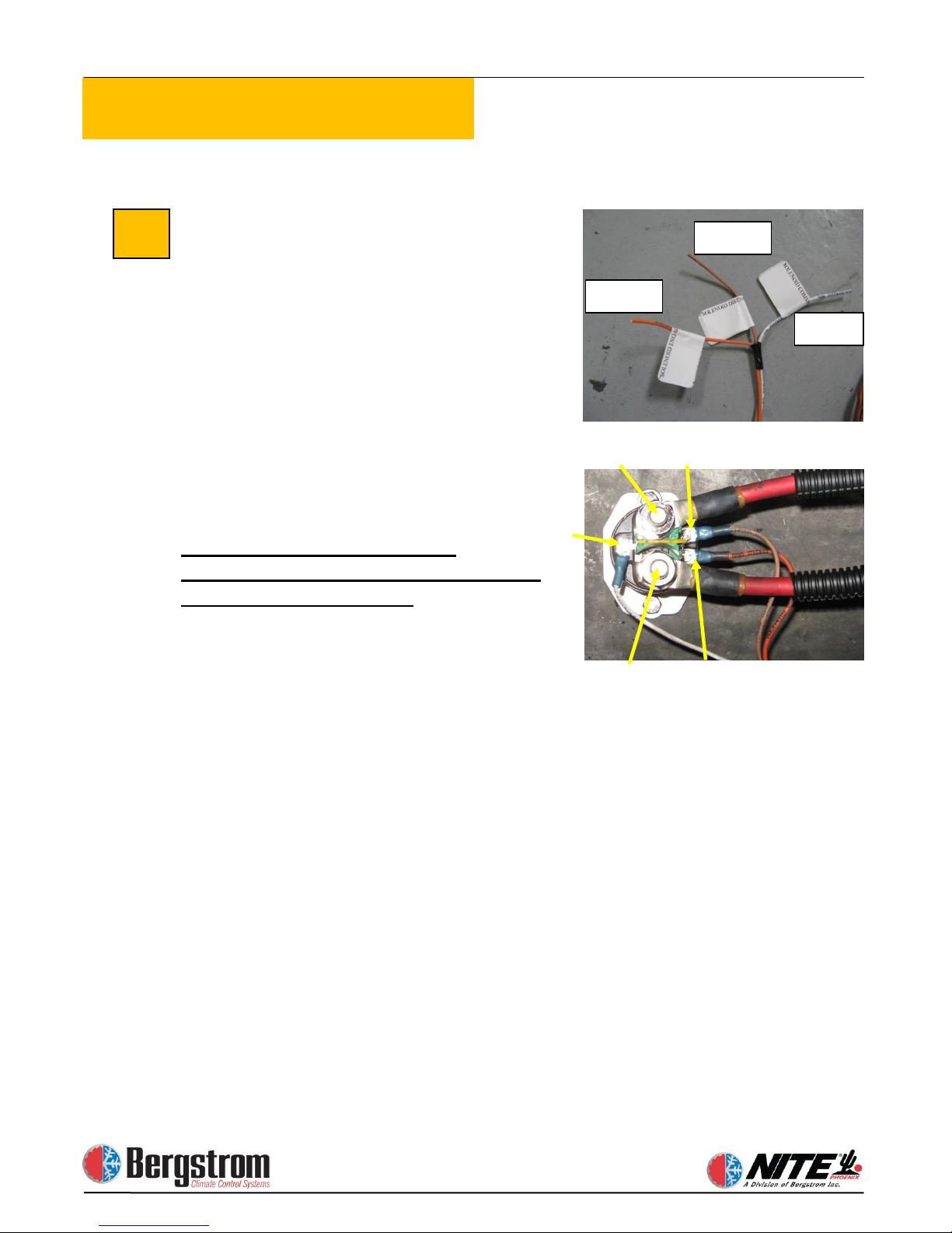
Connect Battery Management System
to Battery Separator Solenoid This 3
wire harness from the 8 pin connector
routes to the battery separator solenoid.
Cut wires to length, crimp snap fork
terminals on each wire and connect to
designated terminals. This switch
separates the Aux batteries from the
starting batteries. It closes when the truck
batteries are at or above 13.2 and opens at
12.5 volts. Location can be in the AUX
battery box, truck starting battery box or
the supplied plastic enclosure.
This harness must be loomed.
Notice: the terminal connecting points
are printed on each wire.
Terminals are marked as:
19
Orange
White
Tan
88 – Starting battery cable (POS)
88A – Aux battery cable (POS)
85 – Solenoid common (White wire)
86A – solenoid disengage (Tan wire)
86B – solenoid engage (Orange wire)
Page 33
2-12
Electrical Installation
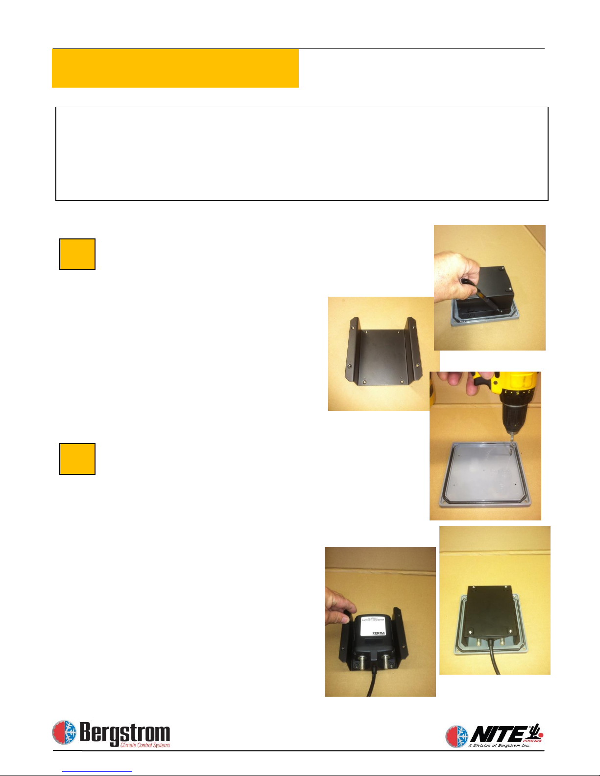
Install Separator Enclosure
Remove the enclosure cover, Place the
separator mounting bracket, centered on
the inside of the cover. Mark and drill 4
holes to secure the bracket to the cover.
Before installing the bracket, secure the
separator to the bracket with four
10 x 32 x ¾″ screws and lock washers
provided.
WIRING THE TERRA POWER SEPARATOR
the separator inside the battery box.
20
21
Disregard the enclosure instructions if you mount
Page 34
2-13
Electrical Installation
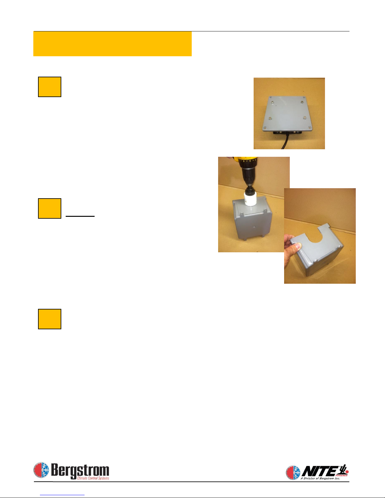
Install the assembly to the cover using 4
10 x 32 x ¾″ screws, lock and flat
washers provided.
Next, drill a 2″ hole in the center of the
bottom
Trim the hole on each side as shown,
creating a 2″ slot.
Install enclosure on truck
22
23
24
of the box as shown.
Page 35
2-14
Electrical Installation
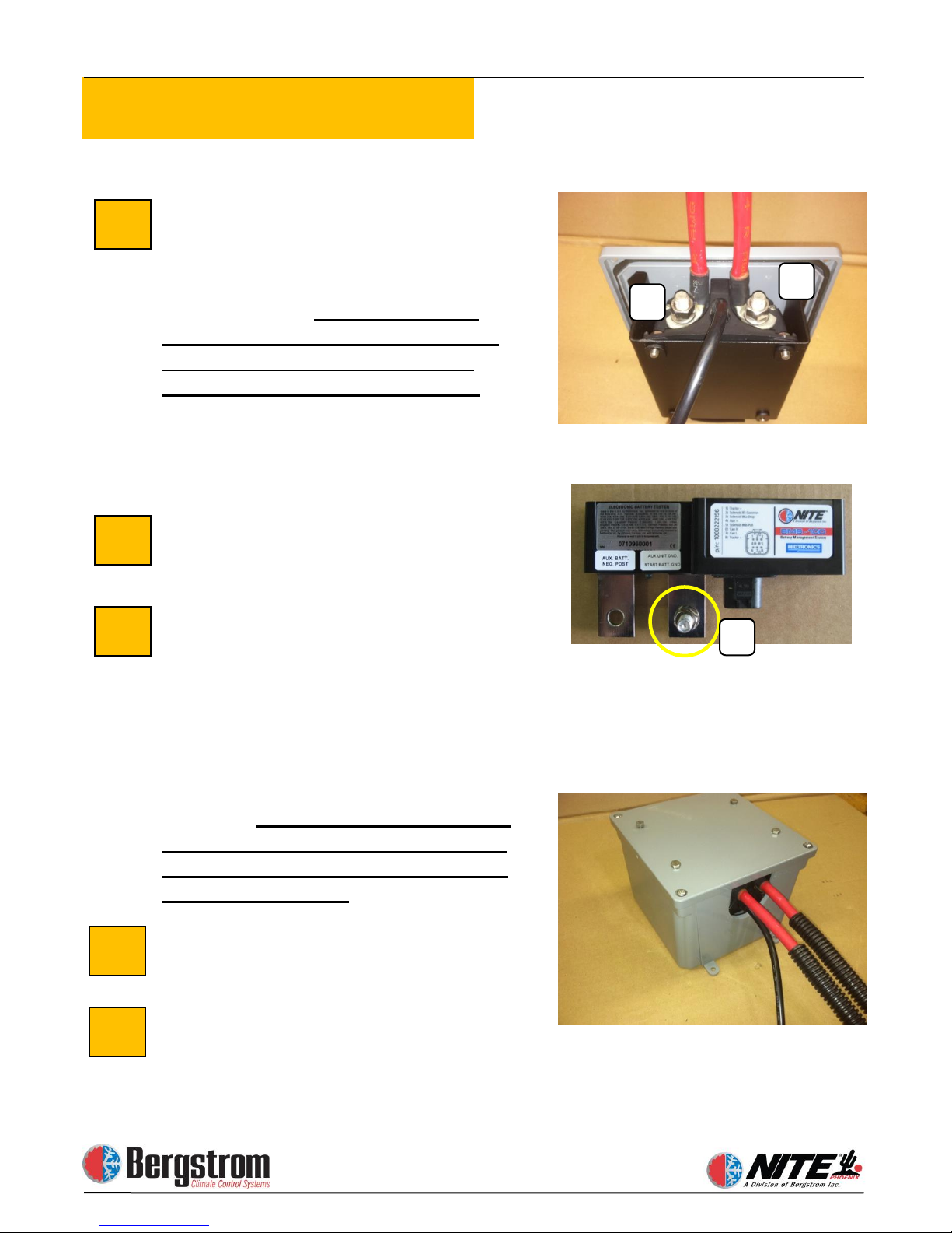
Run Cables from Truck Batteries
Loom 2 full length battery cables, 1 red
and 1 black. The red (pos) cable will
connect the truck starting batteries
positive post to the (start) post (A) of the
battery separator.
provided 90 degree battery terminal
end at the Terra Power separator
rotated to the center of the switch.
Torque specs for separator terminals
88(recommended) to 132(maximum) inch
lbs.
The black (neg) will connect the truck
(neg) to the threaded stud (C) of the
BMS.
Connect
Separator.
measure and cut to proper length. Crimp
ring terminals and heat shrink. Connect
one end to the most appropriate positive
(+) terminal of the NITE Batteries.
Connect the other end to the AUX
terminal (B) of the battery separator. See
top photo.
90 degree battery terminal end at the
Terra Power separator rotated to the
center of the switch
Install the separator assembly
Once you have torque the battery cable
connections, install the cover assembly on
the enclosure.
25
26
27
28
29
A
B
C
You must use the
NITE Batteries to Battery
Using red battery cable,
You must use the provided
.
Page 36
2-15
Electrical Installation
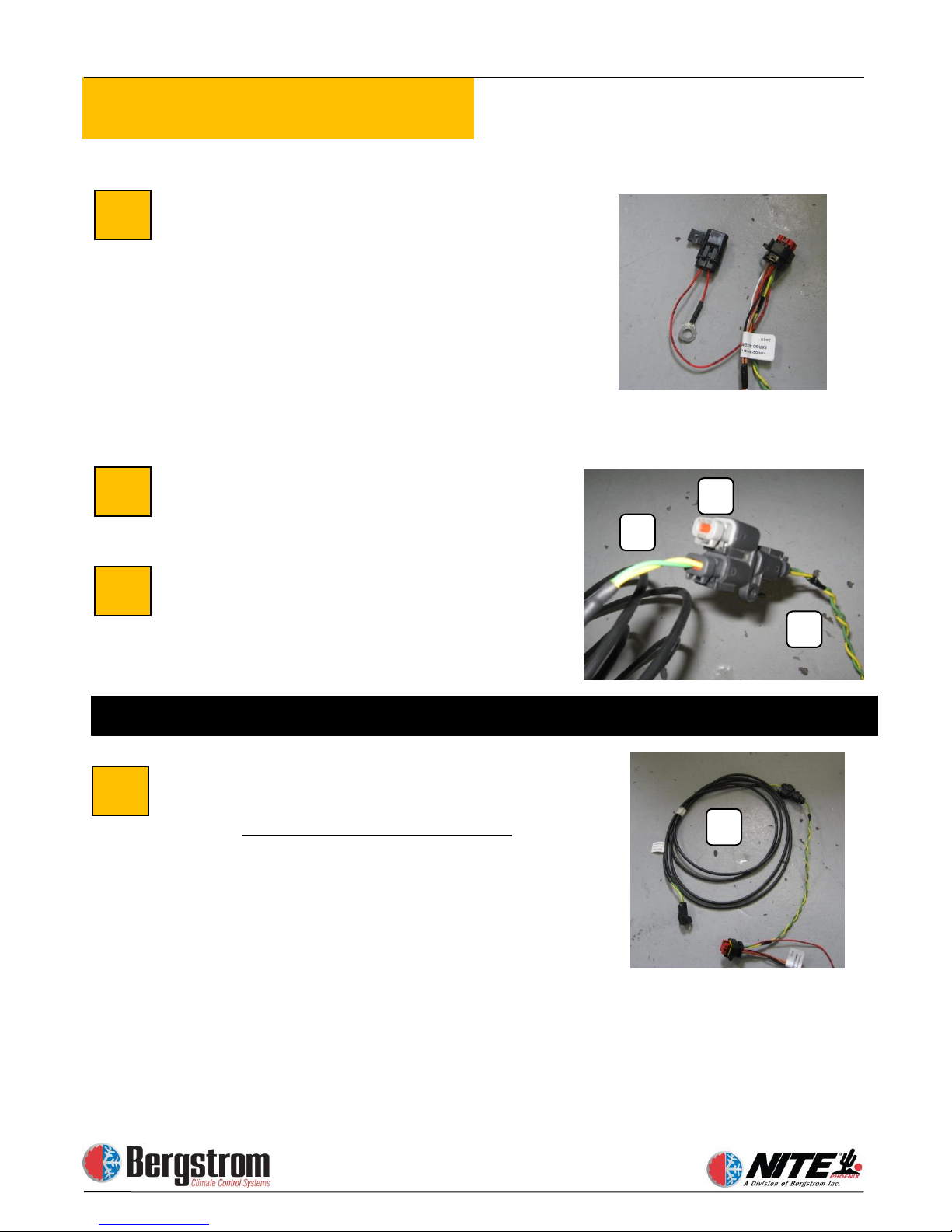
Battery Management System Wiring
Harness.
BMS. Auxiliary battery power wire with
fuse connects to battery pos on the aux.
batteries. This harness splits three ways:
Red/black goes to truck starting batteries,
orange/white go to separator,
green/yellow go to can bus on Phoenix
unit inside the truck. All three must be
loomed.
Install Y connector at BMS connection
(A) - wires green and yellow
Install resistor plug (B) into Y
connector
Connect Can Bus harness from the
Battery Management System wiring
harness.
(C). Route this harness inside the truck
through the floor grommet and connect at
the Phoenix unit.
C
C A B
30
31
32
33
Systems built after 9/1/2013 do not use a Y connector and resistor
8 pin connector plugs into the
This harness must be loomed
Page 37
2-16
Electrical Installation
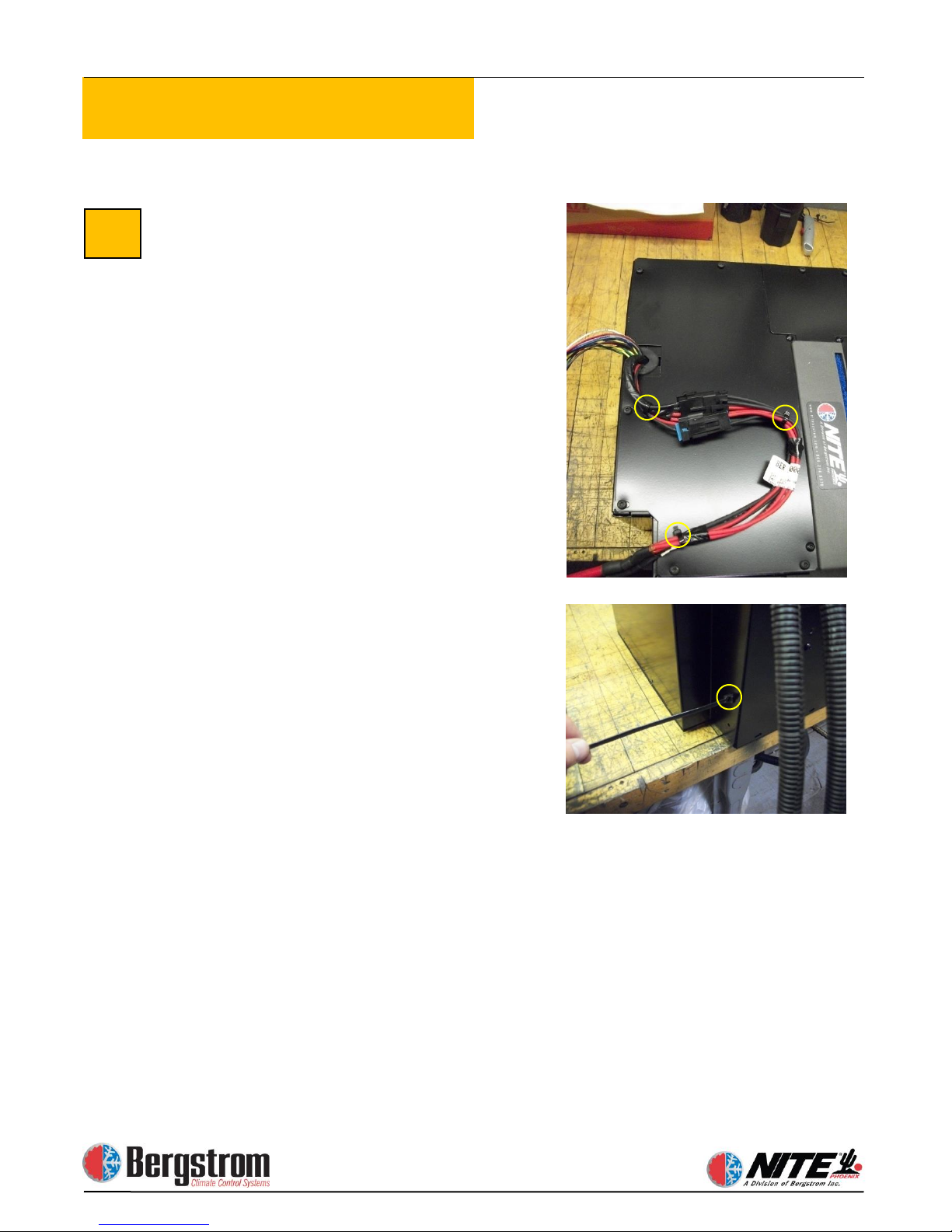
Attach Can Bus Cable to Unit.
Connect can bus harness, coming from
the BMS, into connector at the NITE
Phoenix unit – it only fits one way
Also connect the digital controller
harness installed in an earlier step.
34
.
Page 38
2-17
Electrical Installation
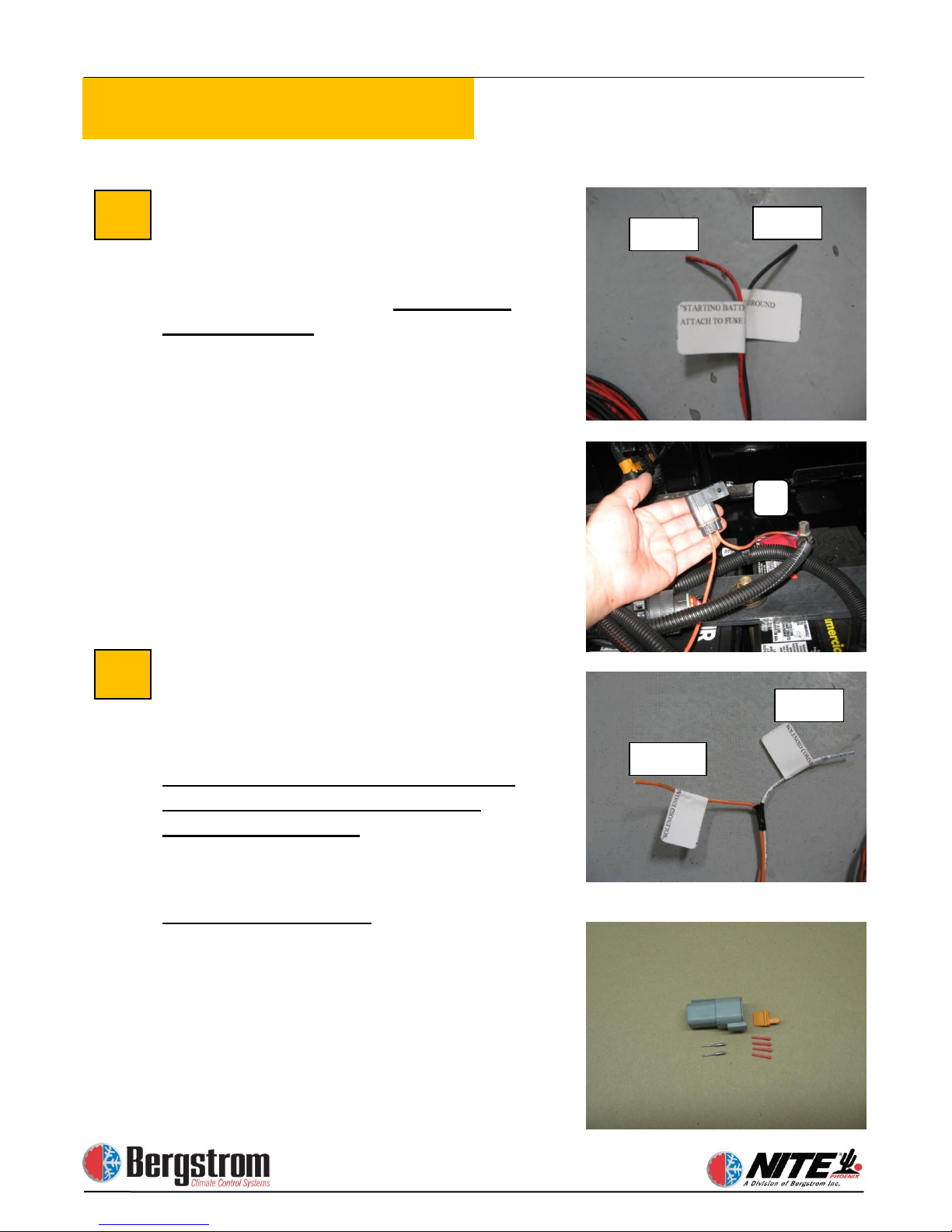
Connect Battery Management System
to Start Batteries. 2 wire harness from 8
pin connector. This harness routes from
the BMS in the Aux battery box to the
truck starting battery box.
must be loomed.
through the supplied, field installed, 5
amp mini fuse and holder (A) to any 12
volt POS post in the truck starting battery
box. The black connects to any 12 volt
NEG post in the battery box. It is vital that
these wires connect in each box.
Connect Battery Management System
to Battery Separator.
harness from the 6 pin connector routes to
the battery separator solenoid.
This harness must be loomed. Notice:
the terminal connecting points are
printed on each wire.
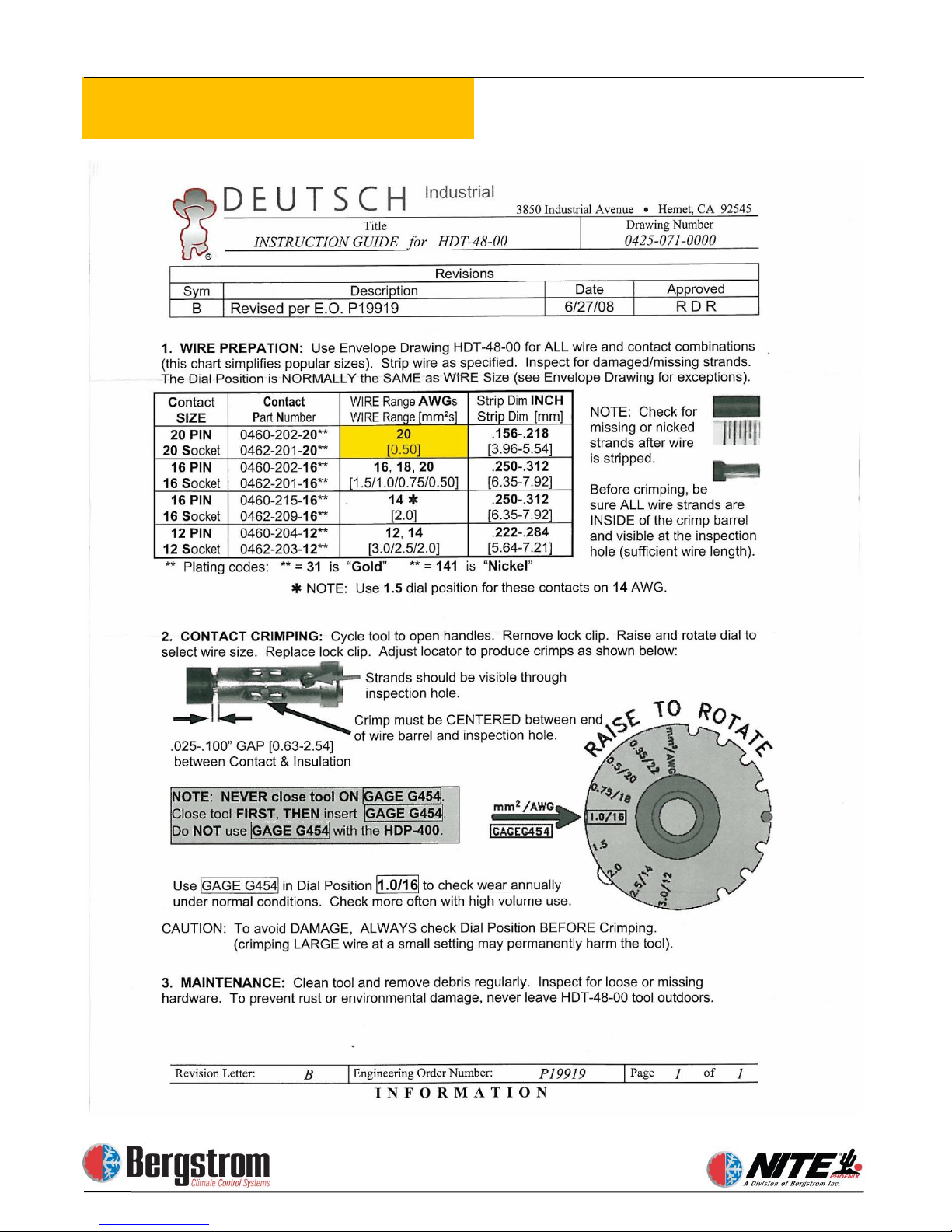
Deutsch connector kit.
This connector connects the orange and
white control wires to the Terra Power
switch. This requires the special Deutsch
crimping tool. See crimping tool
instructions on page
proceeding.
35
36
Red
Black
Orange
White
A
The red connects
This 2 wire
This harness
2-18 before
Page 39
2-18
Electrical Installation
Page 40
2-19
Electrical Installation
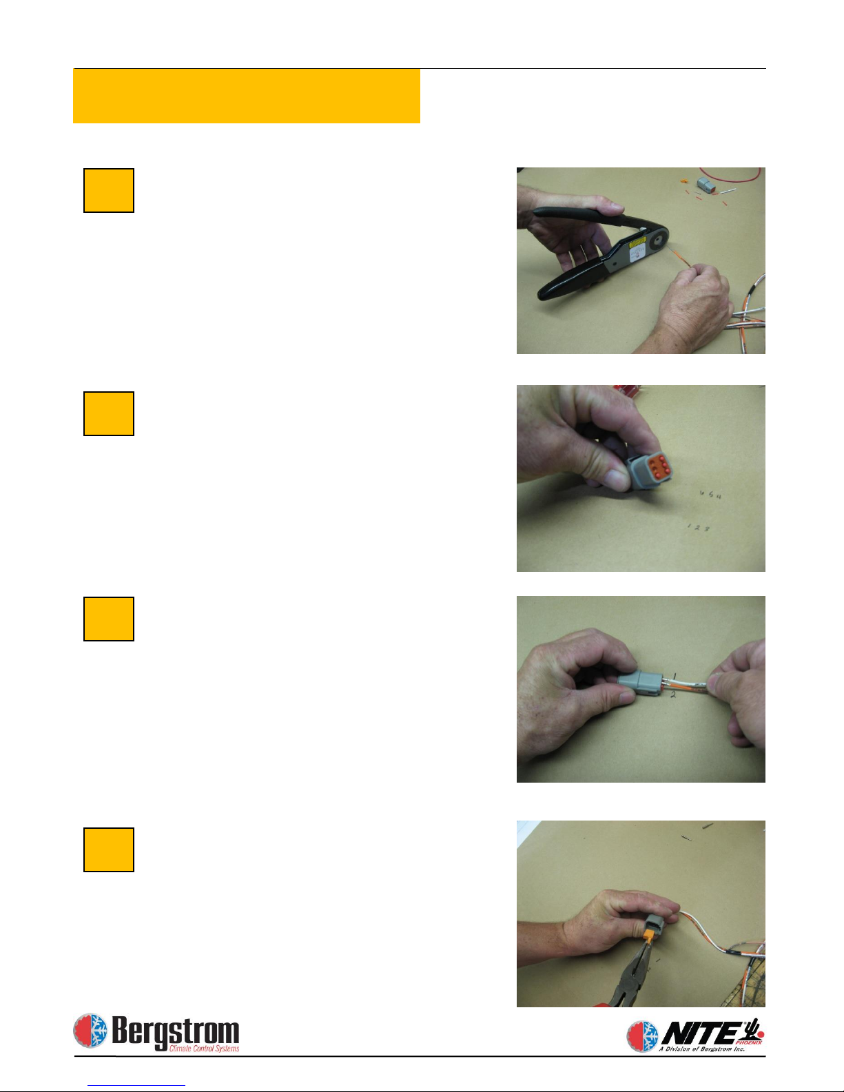
Cut wires to length, strip insulation as
instructed in the Deutsch tool section.
Crimp terminals on each wire.
Install 4 sealing plugs into the unused
terminal locations 3 through 6.
Install separator control wires into
Deutsch connector
Terminals are marked as:
After wires are installed, slide the
terminal lock into place, inside the
connector
37
38
39
40
1– Solenoid common (White wire)
2– Solenoid engage (Orange wire)
Page 41
2-20
Electrical Installation
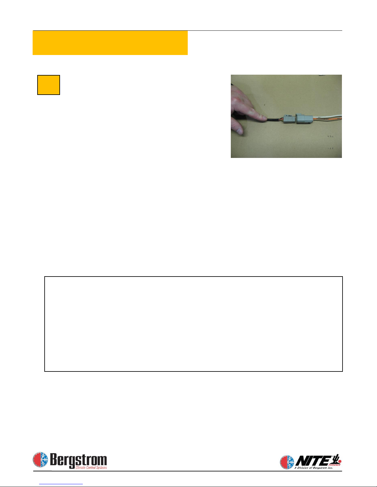
Connect the assembled connector to the
existing connector on the Terra Power
switch
Complete Electrical Wiring
Recheck and tighten all battery and
separator connections. Zip tie cables
where necessary. Your wiring should look
like the diagram on page 5-1.
41
This completes the electrical section of the installation. If you are installing the
ESPAR heater proceed to section 3. If you are installing the WEBASTO heater
proceed to section 4. If you are not installing an aftermarket heater, your
installation is complete and you may reconnect the truck batteries.
WARNING: If you have a fuel operated heater that was installed at the
factory or prior to the Phoenix install, you can continue to operate the
heater with the existing controller.
IF you choose to wire the existing factory installed heater to the Phoenix
controller, YOU WILL VOID THE FACTORY WARRANTY OF THE
HEATER!
Page 42

Section 3
ESPAR Fuel Operated Heater
Installation
Page 43
3-1
Heater Installation
The heater instructions in this manual are generic. For the latest install information
please refer to the Espar D2 heater install manual
WARNING: If you have an Espar fuel operated heater that was installed at the
factory or prior to the Phoenix install, you can continue to operate the heater with
the existing controller. IF you choose to wire the existing factory installed Espar
heater to the Phoenix controller, YOU WILL VOID THE FACTORY WARRANTY
OF THE HEATER!
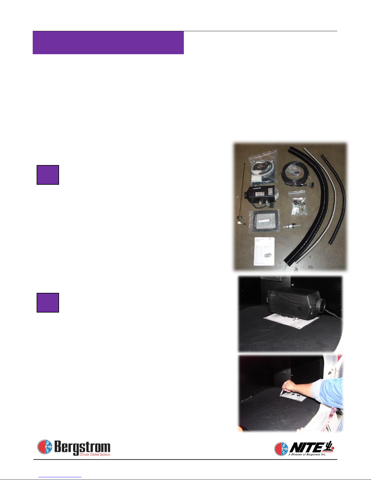
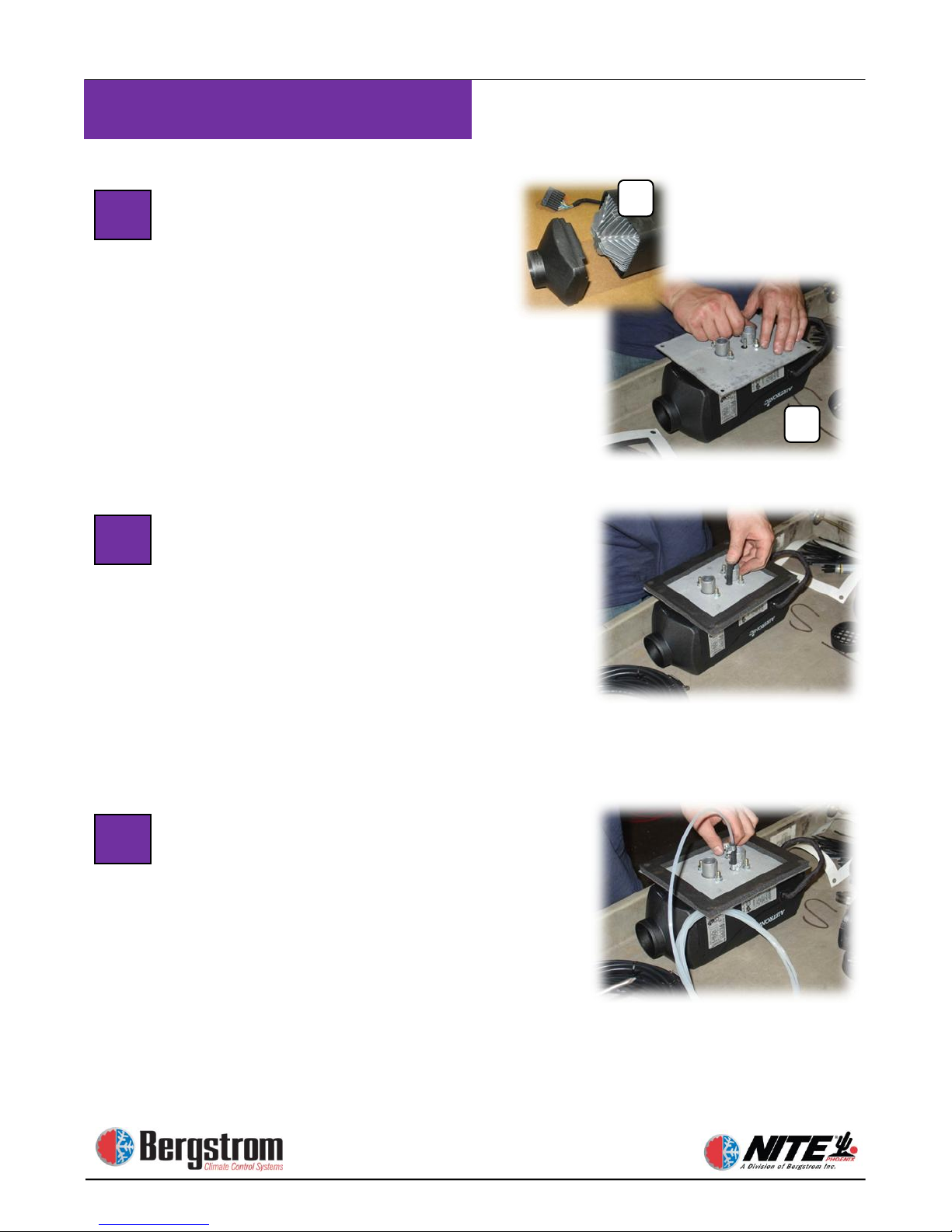
Unpack Heater Parts
Take out the parts to the heating
unit.
Prepare Heater Mounting Location.
Choose the most appropriate location to
install the heater—in this case we have
chosen a side box floor location. Check
underneath truck for any obstructions or
supports. Use the mounting plate as a
template to cut an opening in the rubber
mat. Cut around the mounting plate,
then remove the piece of rubber to
expose truck floor.
1
2
Page 44
3-2
Heater Installation
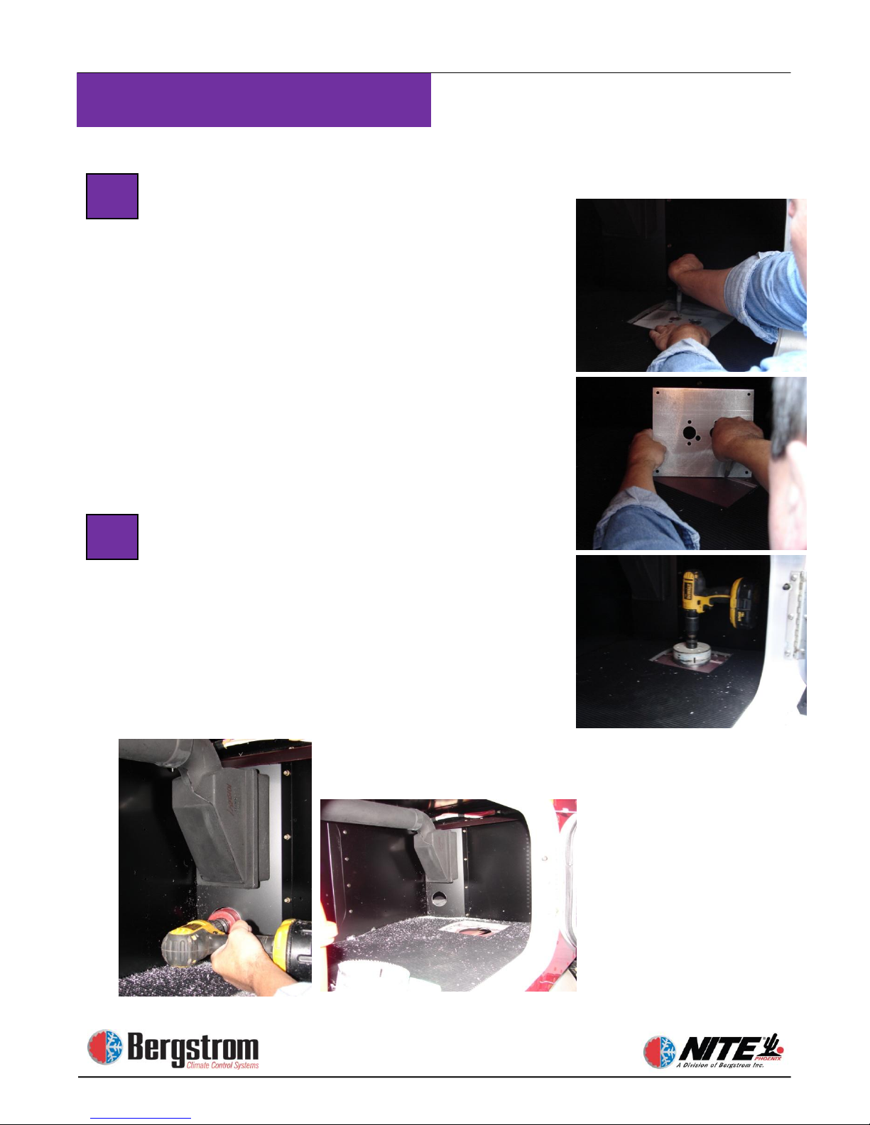
Drill Outlet Hole for Heat Unit. Mark
the floor of the truck using the 5 small
holes of the mounting plate. Remove
mounting plate, place a 4 ¼″ hole saw
over the middle of the floor marks, and
drill the outlet hole for the heater,
intake, exhaust and pickup tube. Also
drill a 1/2″ hole approximately 1 to 2″
from mounting plate corner.
NOTE: DO NOT USE PHOENIX
DUCT FOR HEATER VENT
Install Sleeper Heat Vent. Select
location for the vent in the lower left
side of the center support wall closest to
heater. Drill a 2 ½″ hole (A) to allow
distribution of heat into the sleeper.
After hole is drilled, use 5/16″ x 1″ selftapping screws to attach heat port then
snap louver into place (B).
3
4
Page 45
3-3
Heater Installation
Heater Unit Assembly –Attach
Mounting Plate. Snap end cap on
heater unit (A). Place mounting plate
over heater unit (B). Attach with flat
lock washers and 10mm lock nuts—
tighten down securely.
Heater Unit Assembly – Attach
Gasket and Fuel Line Connection
Peel off backing from gasket and place
gasket over mounting plate edges,
sticky-side down. Place small black
rubber fuel line connector over the fuel
intake tube and push down. Place a
small clamp over connector, push to
bottom and tighten.
Heater Unit Assembly – Attach Fuel
Line
Now take the clear pick up tube, place a
small clamp over it, and push the tube
all the way to the bottom of the fuel
intake tube. Place clamp flush with top
of black connector and tighten securely.
5 6 7
B
A
Page 46
3-4
Heater Installation
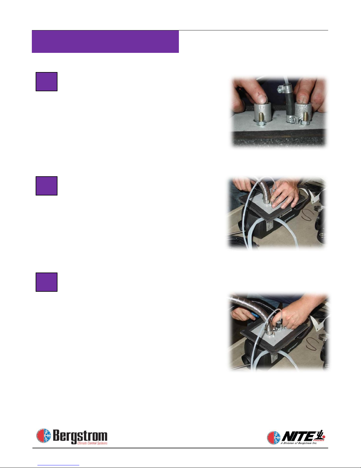
Heater Unit Assembly – Identify
Intake and Exhaust Ports. Look
closely at the two small metal tubes.
One has an arrow pointing out away
from the unit—this is the exhaust. One
has an arrow pointing in towards the
unit—this is the intake.
Heater Unit Assembly – Attach
Exhaust Hose. Take the heavy duty
silver metal hose and place a large,
heavy duty clamp over the end of it.
Place the hose and clamp over the
exhaust tube, push all the way down,
and tighten securely.
Heater Unit Assembly –Attach Intake
Hose. Take the black flex hose and
place a small clamp over the end of it.
Place the hose and clamp over the
intake tube, push all the way down, and
tighten securely.
Heater is now ready to install in the
truck.
8 9 10
Page 47
3-5
Heater Installation
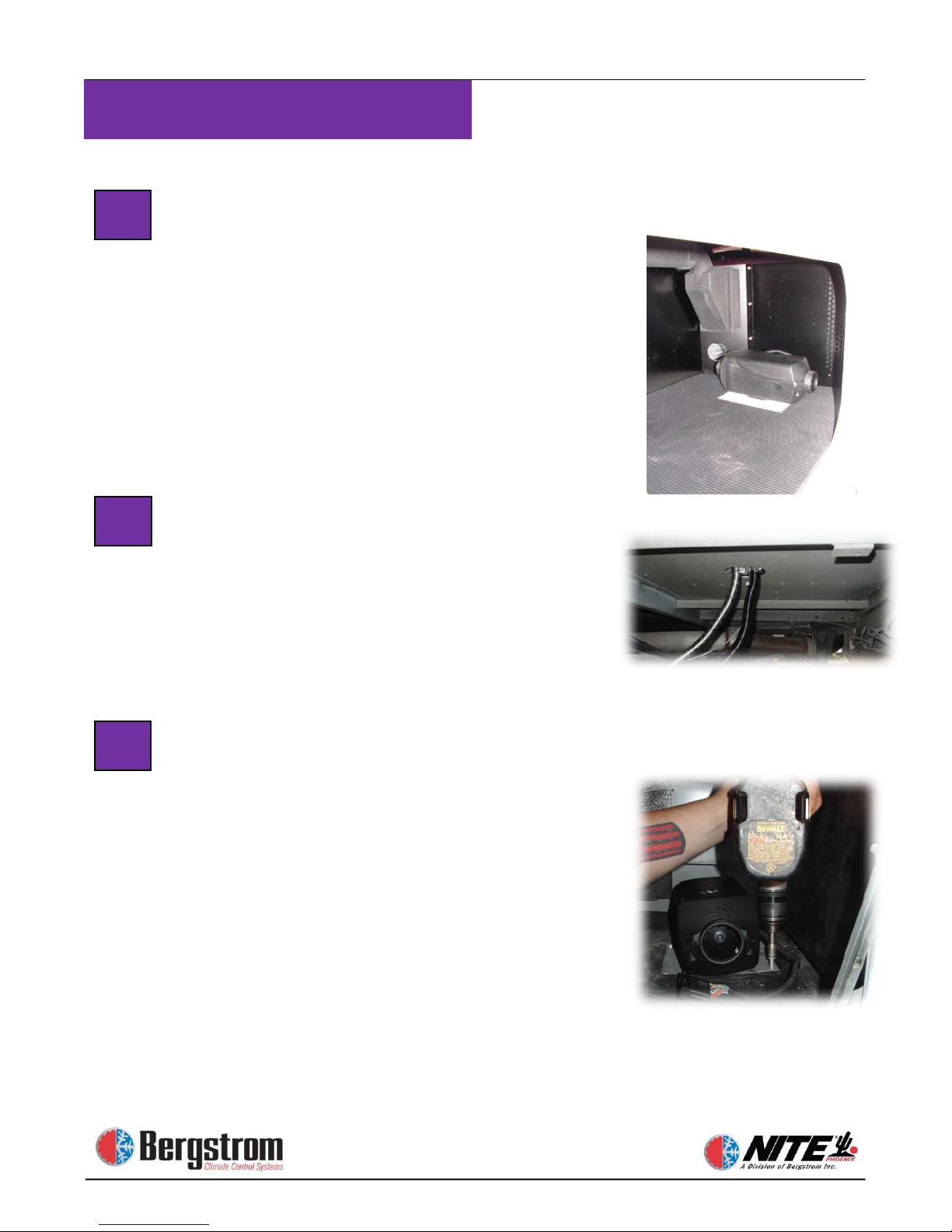
PREPARE TO MOUNT UNIT
Check to make sure truck batteries are still
disconnected. Carry unit into truck. It will
be mounted over the 4 ¾″ hole that was
drilled earlier. Make sure hoses and tubes
don’t get tangled or caught on anything.
Run Lines Through Cab Floor
Feed exhaust hose, intake hose, and fuel
line through the 4 ¾″ hole, making sure
they are not bent, crimped or rubbing on
the side of the hole.
Mount Heater Unit to Cab Floor
Make sure that the heater unit is set with
the fan (intake) end opposite the 2 ½″ hole
for the vent/louver drilled earlier. Set unit
flush to floor and attach with a selftapping screw at each corner of the
mounting plate.
11
13
12
Page 48
3-6
Heater Installation
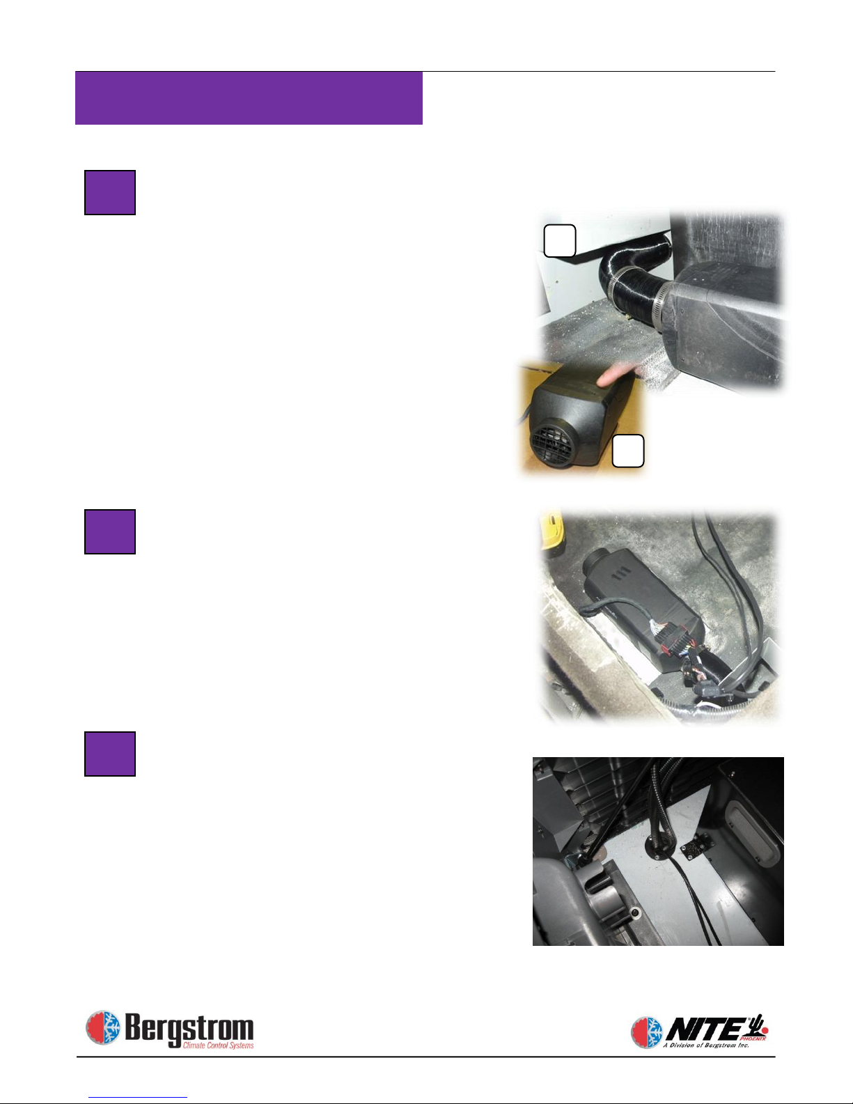
Attach Heat Line to Sleeper Vent.
Take the black metallic flex tube,
measure and cut length to run from
heater unit to louver/vent opening (A).
Place two clamps over ends of tube, and
clamp tube to heating unit and louver.
Tighten clamps securely but do not over
tighten. Snap Intake Grill onto intake
end of heater (B). Keep this area clear
of debris or install return air hose.
Attach Wiring Harness
Attach plug end of wiring harness into
wiring plug at bottom of heating unit.
Be sure the lock-in pin seats securely.
Run Power and Fuel Pump Wires
Through Floor. Run the power wire
and fuel pump power wire through the
grommet (installed in section 1) to the
underside of the truck. If the fuel pump
wire will not reach using this grommet,
use the rubber grommet supplied with
the heater and drill a second hole.
14
15
16
A
B
Page 49
3-7
Heater Installation
Optional Heater controlled by the
Phoenix controller.
WARNING: If you have an Espar fuel
operated heater that was installed at the
factory or prior to the Phoenix install, you
can continue to operate the heater with the
existing controller. IF you choose to wire
the existing factory installed heater to the
Phoenix controller, YOU WILL VOID
THE FACTORY WARRANTY OF
THE HEATER!
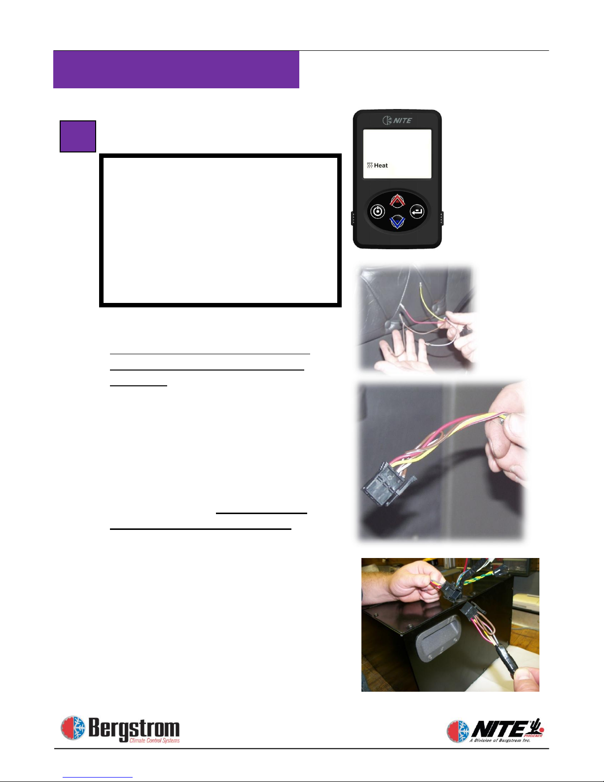
Attach Espar Heater Control
Harness to Phoenix Unit
Espar control harness terminates the
same as when using the Espar mini
controller. Connector kit for the control
harness is included in the heater kit.
Route the control cable along the bed
towards the heater control panel. Use
zip ties as needed. Strip off 6″ of black
outer jacket from cable coming from
heater. Fold all wires back and cut off
the outer jacket, the blue, solid gray and
solid brown wires. Save the brown
wire and make a jumper wire. Strip
down ends of solid brown wire.
Connect one end of solid brown jumper
to brown/white wire. Add clips to ends
of wires and crimp on with crimper. On
connector, the numbers 1, 3, and 5 are
on one side, 2, 4, and 6 are on the other.
Insert wires into plug as follows: 1 = red,
2 = yellow, 3 = other end of jumper
including brown/white wire,
4 = gray with red stripe, 5 = brown jumper.
Now connect the heater control harness
to the Phoenix unit as shown in photo.
17
Page 50
3-8
Heater Installation
B
19
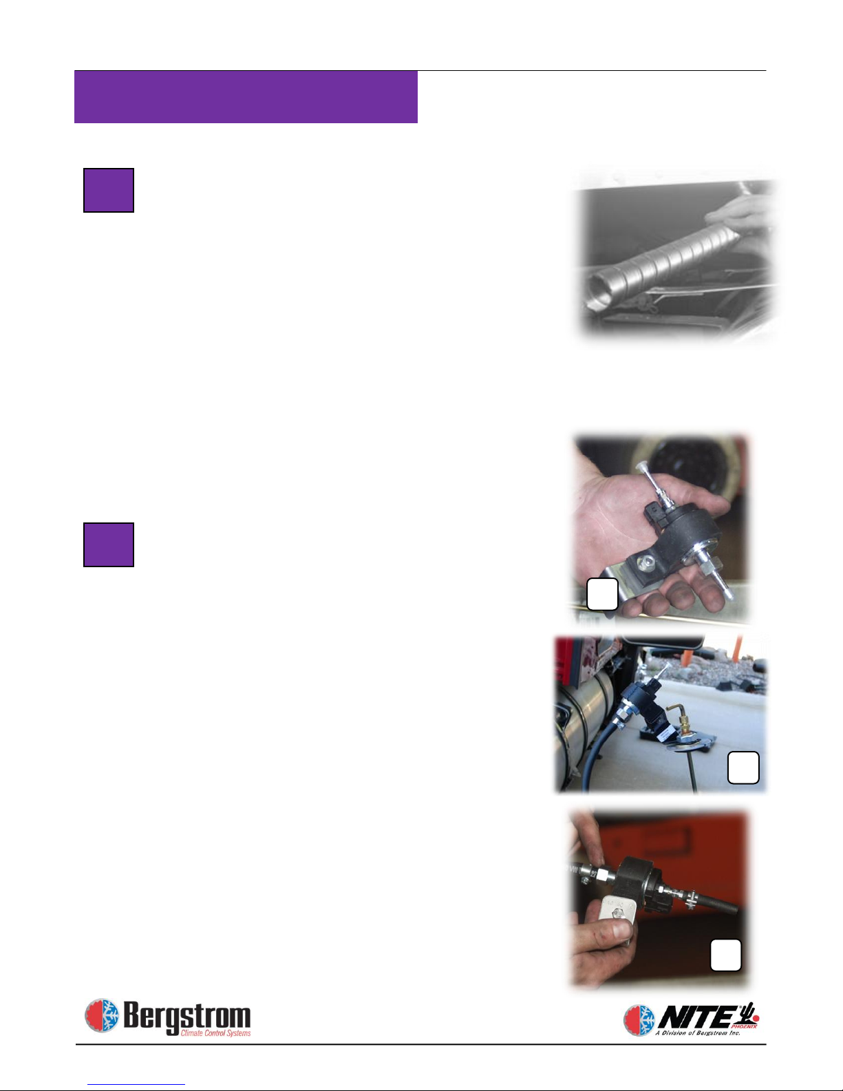
Finish Intake and Exhaust Hose
Installation. First, attach intake air
tube to truck structure with zip ties. Put
cap on bottom of intake tube. Next, run
exhaust hose to the back of cab, attach
with clamps to the structure of the
truck. Cut off excess
exhaust hose, and place End
Sleeve on the end of the hose.
NOTE: HOT – Keep exhaust
hose away from wiring or flammable
material. Make sure exhaust exits
behind the vehicle.
Assemble the Fuel Pump Mount and
Hoses. Take rubber mount bushing and
L bracket and put them together to
make mounting bracket for fuel pump.
Slide fuel pump into rubber bushing
(A). Take plastic caps off both ends of
fuel pump. Attach large fuel hose to
larger diameter end (B), figure out
length needed to connect to pick up tube
and cut off excess. Secure with clamp.
Attach small precut hose to smaller
diameter end of the fuel pump and
secure with clamp (C).
NOTE: Bracket show n in photo (B)
will always set the fuel pump at the
desired angle. Make sure the inlet of the
fuel pump is down.
18
A
C
Page 51
3-9
Heater Installation
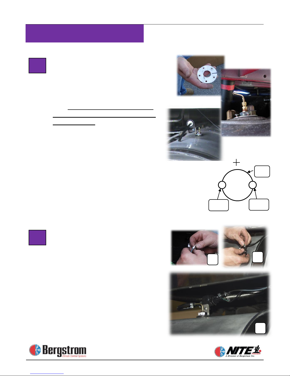
Drill Hole in Fuel Tank, Insert
Pickup Tube and Mount Fuel
Assembly. Use a 1″ hole saw to scribe
initial location for two outer holes. Drill
the two outer 1/4″ holes centered on
scribe. Then complete drilling the 1″
hole. See diagram A. Option: When
possible drill holes in the fuel sender
block off plate. Slide pickup tube into
fuel tank through hole, install with
bottom washer then put on rubber seal
and place metal washer on top of pickup
tube followed by pump mounting
bracket and nut. Tighten slightly. Put
clamp over end of large fuel line from
fuel pump, attach to pickup tube and
clamp down. Finish snugging up large
nut, but do not over tighten. Cut off
excess from small feeder tube fuel line
and attach to fuel pump. Secure with
clamp.
Prepare and Attach Fuel Pump
Harness. Measure and cut fuel pump
harness wires to appropriate length.
Strip wires, put on rubber boots, then
attach ends and crimp (A). Attach wires
to plug: 1 = green, 2 = brown. Make
sure rubber boots are seated to keep out
moisture (B). Connect the harness
spring loaded plug to the fuel pump (C).
Secure all wires and hoses with zip ties.
A
B
20
21
C
1/4″
Diagram A
Hole drilled in blank
sending unit plate
Hole drilled in tank
1/4″
1″
Page 52
3-10
Heater Installation
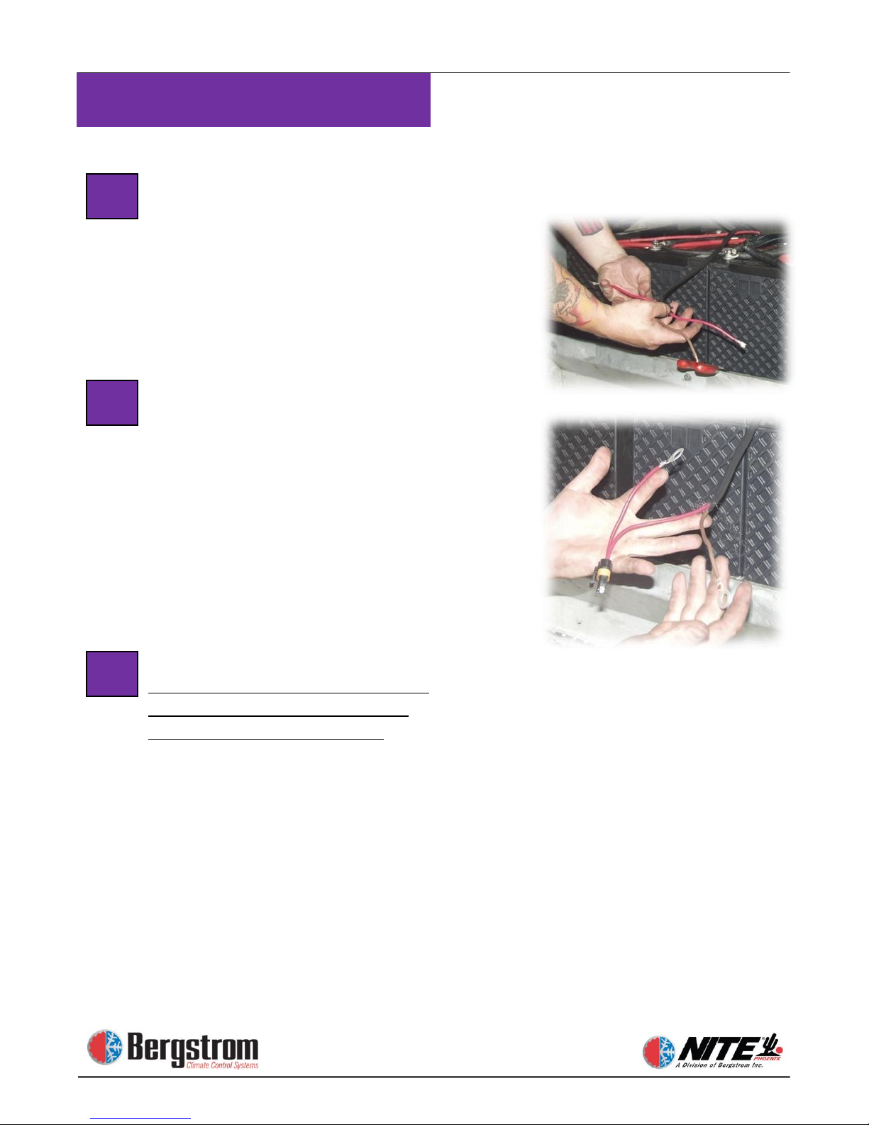
Run Heater Unit Power Cable to
NITE Batteries. Take the heater unit
power cable, run it under the truck
(attach with zip ties where necessary)
over to the NITE Batteries. Strip back
outer cover to expose two inner wires.
Attach Connectors. Strip end off
brown wire. Before stripping red wire,
put the housing of the fuse holder on,
and pull the red wire through. Now strip
the end of the red wire, attach terminal
and crimp. Pull red wire back into fuse
holder. Push rubber seal into place.
Attach ring terminal to ground wire and
crimp.
Attach Wires to NITE Batteries.
Connect Aux heater ground wire to
ground terminal threaded stud of
Battery Management System. Connect
heater unit positive wire to positive
terminal of NITE Batteries. Insert 20
amp fuse into fuse holder. Tighten all
connections.
YOU CAN NOW RECONNECT
THE TRUCK’S BATTERIES TO
TEST THE SYSTEM.
22
23
24
Page 53

Section 4
WEBASTO Fuel Operated Heater
Installation
Page 54
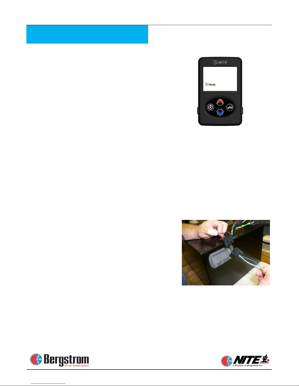
4-1
Heater Installation
Optional Webasto Heater controlled
by the Phoenix controller.
WARNING: If you have a Webasto
fuel operated heater that was installed at
the factory or prior to the Phoenix
install, you can continue to operate the
heater with the existing controller. IF
you choose to wire the existing factory
installed Webasto heater to the Phoenix
controller, YOU COULD VOID THE
FACTORY WARRANTY OF THE
HEATER!
DO NOT USE PHOENIX DUCT FOR
HEAT VENT.
ATTN: Refer to Webasto manual for
all heater installation instructions
then proceed to steps below for
connecting Webasto heater to the
Phoenix unit.
Attach Webasto heater control harness
to Phoenix Unit. Route the control
cable along the bed towards the Phoenix
unit. Use zip ties as needed.
Now connect the heater control harness
to the Phoenix unit harness (as shown in
photo). The Webasto heater in the
Phoenix kit is prewired to connect
directly into the Phoenix unit harness.
For pin numbers and wire colors see
wiring diagram in section 5.
Page 55

Rev 7/10/14
Section 5
Wiring Diagrams
NOTE:
Pages 5-1 and 5-2 are for unit manufactured after 2/8/2012
Pages 5-3 and 5-4 are for units manufactured prior to 2/8/2012
Page 56
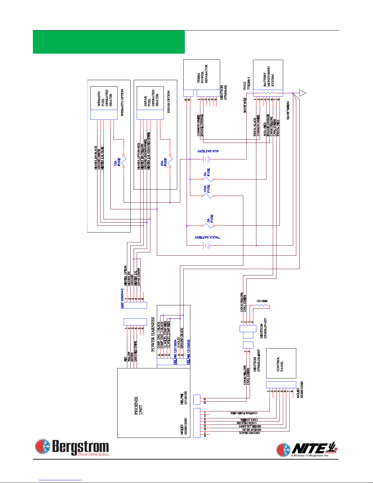
5-1
External Wiring Diagram
Use for units manufactured after 2/08/2012
Page 57
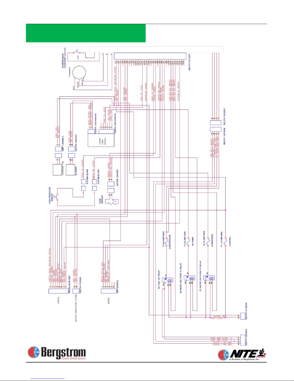
5-2
Internal Wiring Diagram
Use for units manufactured after 2/08/2012
Page 58
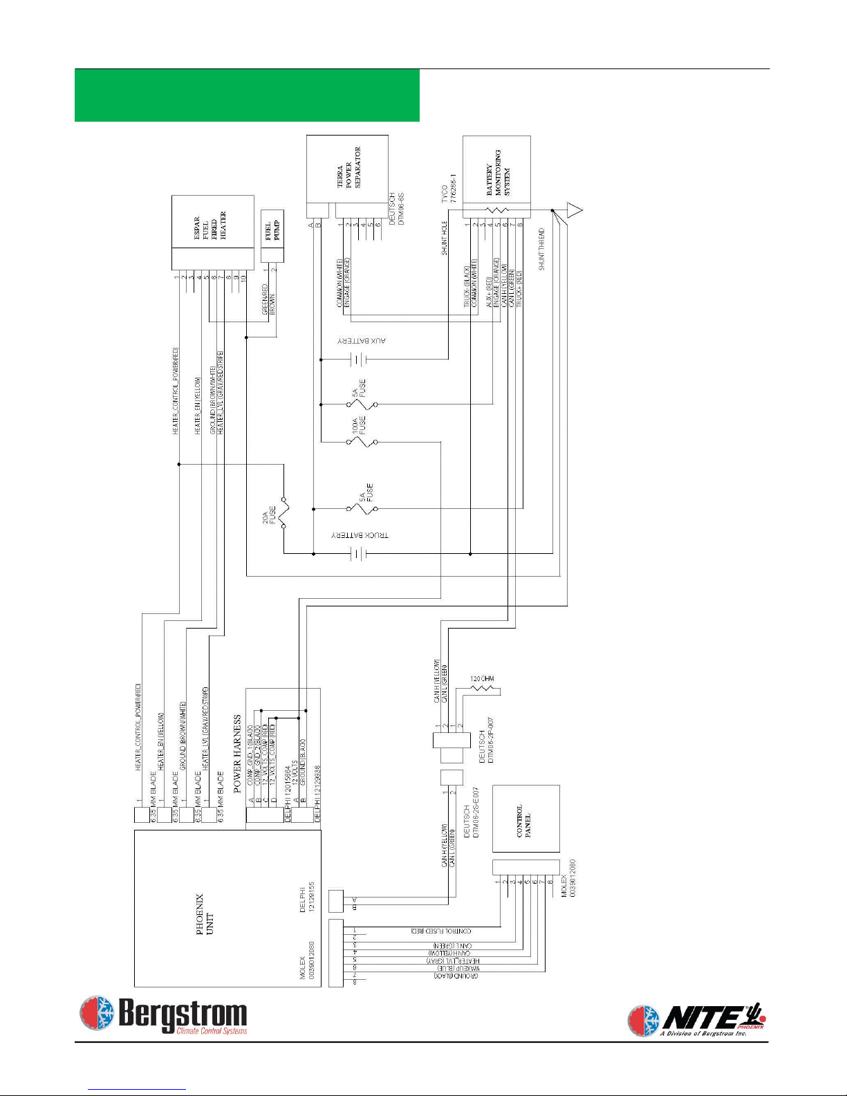
5-3
External Wiring Diagram
Use for units manufactured prior to 2/08/2012
Page 59
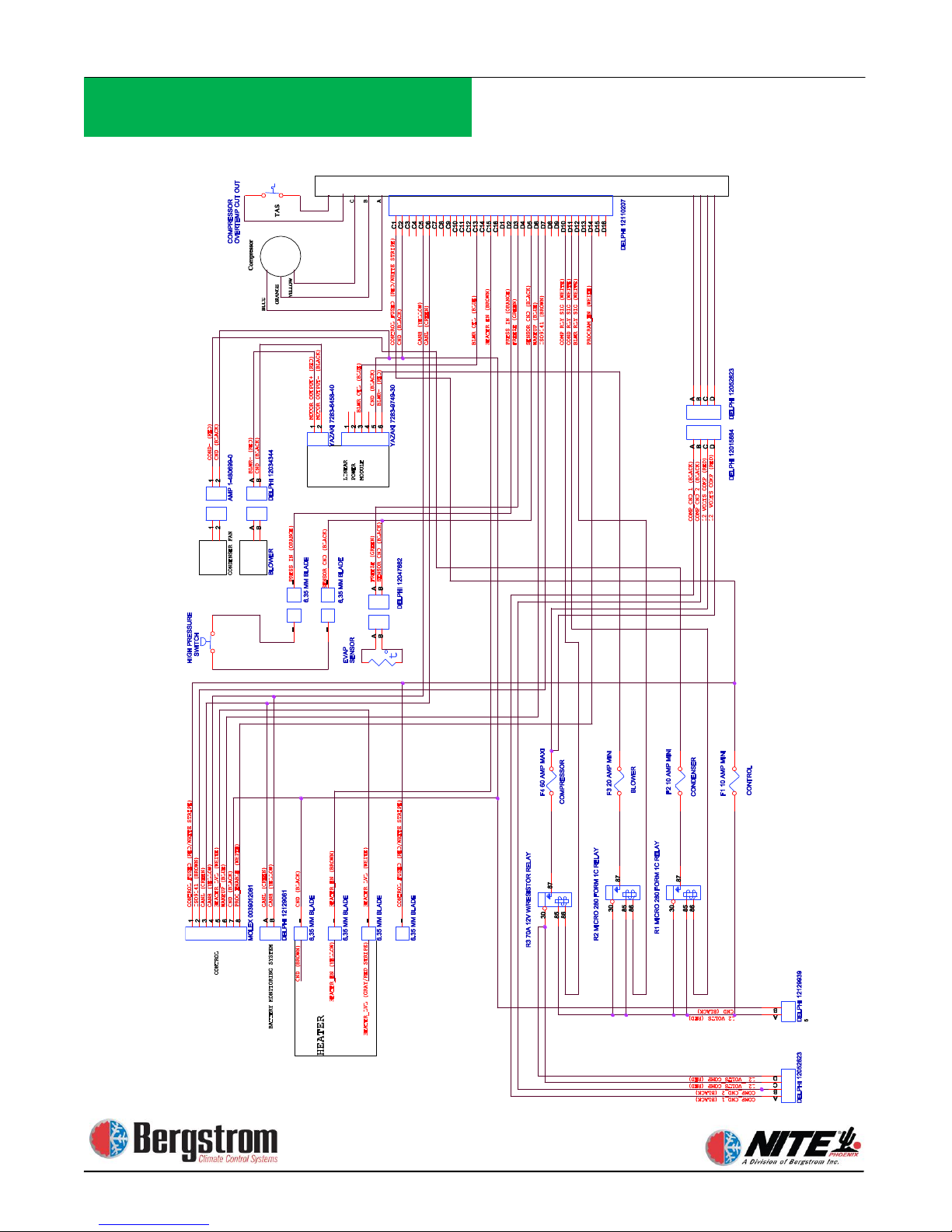
5-4
Internal Wiring Diagram
Use for units manufactured prior to 2/08/2012
Page 60

Operating Instructions
Section 6
Page 61
6-1
Operating Instructions
ON/OFF
ENTER
ENTER
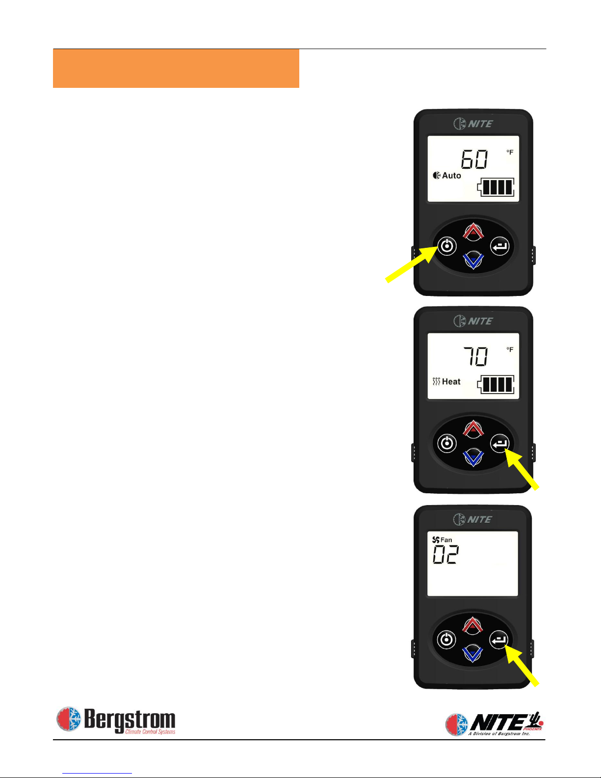
To start the system push ON/OFF button. Display will
show current mode/ temperature setting / battery level.
Initial default setting is blower speed 1/ AUTO- MODE /60 °F
Changing MODE – press ENTER, while mode is flashing
use up or down arrows to select AUTO / COOL / HEAT.
After 5 seconds selection will be set.
Changing BLOWER SPEED – press ENTER until display
shows FAN and SPEED. Press up or down arrows to
select 1 – 2 – 3 speed. After 5 seconds selection will be
set.
Page 62
6-2
Operating Instructions
ENTER
ENTER
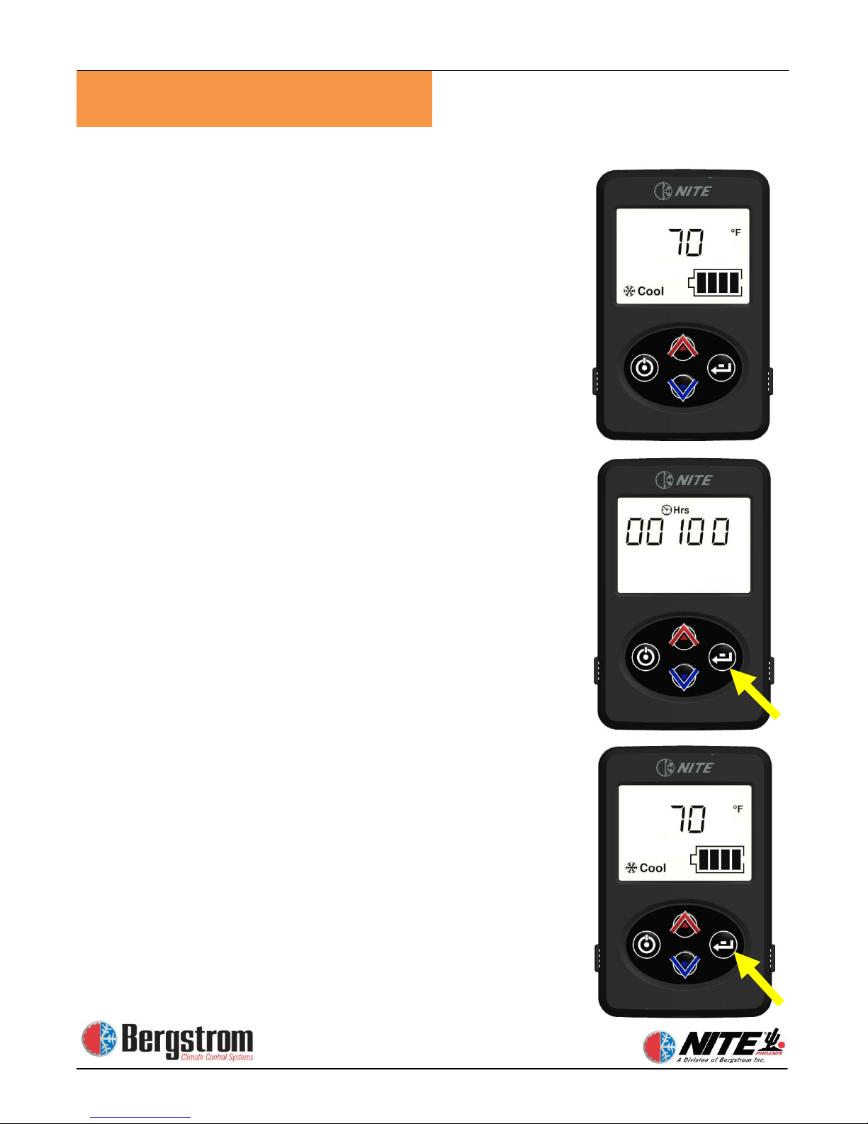
Changing TEMPERATURE set point. Anytime the
temperature set point is displayed on the screen, push
the up or down arrows to change. Temperature range
is from 60 °F (coolest) to 85 °F (warmest).
NOTE: Control will always default to the last setting
when the unit is turned on.
To view system runtime/hours – press ENTER until
“Hrs” show on display. When hours are displayed,
pressing ENTER for 7 seconds will reset the hours to
zero.
To change from °F to °C press ENTER until temperature
symbol only shows – push the up or down arrow to
change. After 5 seconds selection will be locked.
Anytime the control is idle for 5 seconds the screen will
return to the temperature set point screen.
Page 63
6-3
Operating Instructions
ENTER
ON/OFF
ENTER
ENTER
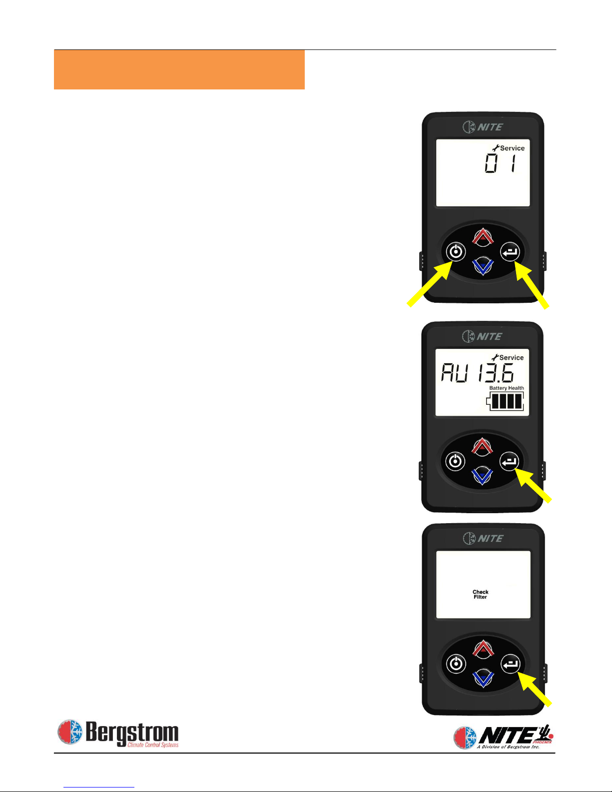
To enter SERVICE MODE: Push both the ON/OFF and
ENTER button simultaneously at any time.
Display will show service indicator and a code #1 to #3.
Use up and down arrows to scroll through the Fault
Codes.
1) Evap sensor open or shorted high
2) Evap sensor shorted low
3) High pressure switch open or shorted high
Press the ENTER button to proceed through the
available service screens.
1) SV = Starting batteries Voltage
2) AV = Auxiliary batteries Voltage
3) AA = Unit Amperage draw
4)
Pressing ENTER arrow after viewing service screen will
return you to the fault code screen.
Pressing the ON/OFF button will return you to the
Temperature Display screen.
When necessary, Check Filter light will notify you that
the Phoenix filter must be cleaned or changed. To reset
filter: at screen 1 press and hold enter button for 3
seconds.
Page 64

Section 7
Battery Management
System (BMS) Installation
Page 65
7-1
Battery Management
Bergstrom NITE System
BMS 100 Installation
Page 66
7-2
Battery Management
Page 67
7-3
Battery Management
 Loading...