

Page 1
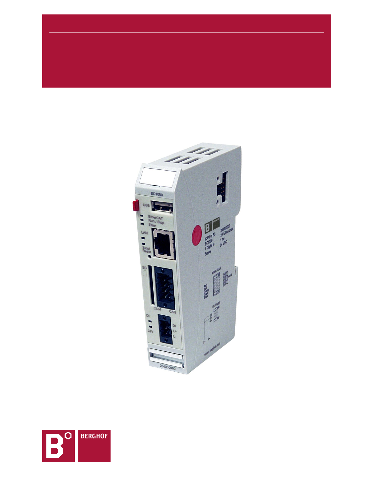
USER MANUAL 1.7
EC1000
Ethernet-Controller
Page 2

Copyright © Berghof Automation GmbH
Reproduction and duplication of this document and 2ft he2tion and communication of its content is
prohibited, unless with our express permission. All rights reserved. Damages will be payable in case of infringement.
Disclaimer
The content of this publication was checked for compliance with the hardware and software described. However, discrepancies may arise, therefore no liability is assumed regarding complete compliance. The information in this document will be checked regularly and all necessary corrections will be included in subsequent editions. Suggestions for improvements are always welcome.
Subject to technical changes.
Trademarks
CANtrol® and CANtrol®- dialog are registered trademarks of Berghof Automation GmbH
Microsoft®, Windows® and the Windows® Logo are registered trademarks of Microsoft Corporation in
the USA and other countries.
EtherCAT® is a registered trademark and patented technology, licensed from Beckhoff Automation
GmbH, Germany.
CiA® and CANopen® are registered community trademarks of CAN in Automation e.V.
All rights reserved by the individual copyright holders.
General Information on this Manual
This equipment manual contains product-specific information valid at the time of publication.
This equipment manual is only complete in conjunction with the product-related hardware and software user
manuals required for the individual application.
You can reach us at:
Berghof Automation GmbH
Harretstr. 1
72800 Eningen
Germany
T +49.7121.894-0
F +49.7121.894-100
e-mail: [email protected]
www.berghof.com
Berghof Automation GmbH works in accordance with DIN EN ISO 9001:2000.
Content
Completeness
Page 3

USER MANUAL 1.7 | EC1000
Berghof Automation GmbH | Harretstrasse 1 | 72800 Eningen | www.berghof.com
EC1000_HB_en_2D1652008ZD00.docx
3
Update
Version
Date
Subject
1.01
25.09.2012
First Version
1.1
31.10.2012
Update of chapter ‘Product description, Block diagram’
1.2
09.11.2012
Update 3ft he trademarks
1.3
06.02.2013
Update of chapter ‘Annex, Nameplate’ and ‘Annex, Addresses’
Transition into new CD
Update of the title page
Update of chapter ‘Product description, Module view and pin assignment’
Update of chapter ‘Product description, Technical data’ and ‘Product
description, Identification’
1.4
20.05.2014
New corporate name ‘Berghof Automation GmbH’
UL certification
1.5
19.10.2015
Update of chapter ‘General Information, Working on the controller module’
Update of chapter ‘Annex, Nameplate’
1.6
01.02.2017
Update of chapter ‘General Information, Conformity Declaration’
Update of chapter ‘Product description, Technical data’
Update of chapter ‘Product description, Module view and pin assignment’
Update of chapter ‘Function Selection, Indicators, Diagnostics, Status
Indicators’
Update of chapter ‘Annex, Nameplate’
1.7
25.05.2018
New device 204900002
New device 204900102
Update of chapter ‘General Information, Conformity Declaration’
Update of chapter ‘Product description, Overview, Accessoires’
Update of chapter ‘Product description, Technical data’
Update of chapter ‘Product description, ’Mounting and connecting, Mounting’
Update of chapter ‘Controller operation, ’Real-Time Clock with Backup Battery’
Update of chapter ‘Annex, Bibliography / Standards’
Page 4

USER MANUAL 1.7 | EC1000
Berghof Automation GmbH | Harretstrasse 1 | 72800 Eningen | www.berghof.com
EC1000_HB_en_2D1652008ZD00.docx
4
Blank page
Page 5

USER MANUAL 1.7 | EC1000
Berghof Automation GmbH | Harretstrasse 1 | 72800 Eningen | www.berghof.com
EC1000_HB_en_2D1652008ZD00.docx
5
Contents
1. GENERAL INFORMATION ................................................................................................................. 7
1.1. About This Manual ............................................................................................................................. 7
1.2. Hazard Categories and Terminology ................................................................................................ 8
1.3. Conformity Declaration ...................................................................................................................... 8
1.4. Qualified Personnel ............................................................................................................................ 9
1.5. Due Diligence...................................................................................................................................... 9
1.5.1. Working on the controller module ......................................................................................................... 9
1.6. Use as Prescribed ............................................................................................................................ 10
2. PRODUCT DESCRIPTION EC1000 .................................................................................................. 11
2.1. Overview ........................................................................................................................................... 11
2.2. Technical data ................................................................................................................................... 13
2.3. Block diagram................................................................................................................................... 15
2.4. Identification ..................................................................................................................................... 16
2.5. Module view and pin assignment ................................................................................................... 16
2.6. Mounting and connecting ................................................................................................................ 17
2.6.1. Mounting ............................................................................................................................................ 17
2.6.2. Connecting ......................................................................................................................................... 18
2.6.3. Earth ................................................................................................................................................... 19
2.7. Pin assignment ................................................................................................................................. 20
2.7.1. 10/100 Base-T network connection (Ethernet) ................................................................................... 20
2.7.2. USB .................................................................................................................................................... 20
2.7.3. CAN bus and serial interface .............................................................................................................. 22
2.7.4. EtherCAT ............................................................................................................................................ 23
2.7.5. SD Card ............................................................................................................................................. 24
3. CONTROLLER OPERATION ............................................................................................................ 25
3.1. Commissioning ................................................................................................................................ 25
3.2. Function Selection, Indicators, Diagnostics .................................................................................. 25
3.2.1. Status Indicators................................................................................................................................. 25
3.3. Real-Time Clock with Backup Battery ............................................................................................ 27
4. ANNEX ............................................................................................................................................... 29
4.1. Environmental Protection ................................................................................................................ 29
4.1.1. Emission ............................................................................................................................................. 29
4.1.2. Disposal ............................................................................................................................................. 29
4.2. Maintenance/Upkeep ........................................................................................................................ 29
4.3. Repairs/Service ................................................................................................................................ 29
4.3.1. Warranty ............................................................................................................................................. 29
4.4. Nameplate ......................................................................................................................................... 30
Nameplate descriptions (example) ..................................................................................................... 30
Page 6

USER MANUAL 1.7 | EC1000
Berghof Automation GmbH | Harretstrasse 1 | 72800 Eningen | www.berghof.com
EC1000_HB_en_2D1652008ZD00.docx
6
4.5. Addresses and Bibliography / Standards ...................................................................................... 31
4.5.1. Addresses .......................................................................................................................................... 31
4.5.2. Bibliography / Standards .................................................................................................................... 32
Page 7

USER MANUAL 1.7 | EC1000
Berghof Automation GmbH | Harretstrasse 1 | 72800 Eningen | www.berghof.com
2VF100185FE05.docx | EC1000_HB_en_2D1652008ZD00.docx
7
1. General Information
Documentation
This equipment manual is intended for qualified personnel and contains information regarding mounting,
installation, commissioning and maintenance. The information contained in this manual is subject to change
without prior notice.
1.1. About This Manual
This equipment manual is an integral part of the product. Make sure the equipment manual is always available near the product’s point-of-employment. The manual contains information about the following topics:
Areas of application;
Safety;
Mechanical construction;
Electrical construction;
Connections;
Commissioning;
Care and maintenance;
Decommissioning;
Disposal.
Page 8
USER MANUAL 1.7 | EC1000
Berghof Automation GmbH | Harretstrasse 1 | 72800 Eningen | www.berghof.com
EC1000_HB_en_2D1652008ZD00.docx | 2VF100185FE05.docx
8
1.2. Hazard Categories and Terminology
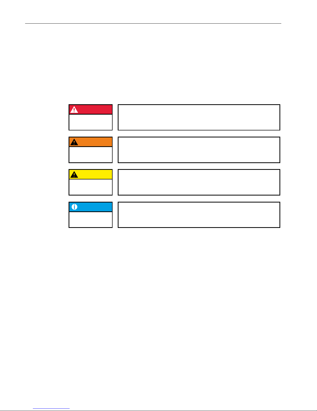
The indications described below are used in connection with safety instructions you will need to observe for
your own personal safety and the avoidance of damage to property.
The indications have the following meaning:
DANGER
Immediate danger
Failure to observe the information indicated by this warning will result in death,
serious injury or extensive property damage.
WARNING
Potential danger
Failure to observe the information indicated by this warning may result in
death, serious injury or extensive property damage.
CAUTION
Danger
Failure to observe the information indicated by this warning may result in injury
or property damage.
NOTICE
No hazard
Information indicated in this manner provides additional notes concerning the
product.
1.3. Conformity Declaration
Both the standard version of the controller module and the extension modules mentioned below comply with
and make allowance for the following directives and standards:
EMC Directive 2014/30/EU
RoHS Directive 2011/65/EU
DIN EN 61131-2: Programmable controllers
Part 2: Equipment requirements and tests
EN 50581: Technical documentation for the assessment of electrical and electronic products with
respect to the restriction of hazardous substances
UL 508: Industrial Control Equipment
17 th edition / 1999-01-28
Page 9
USER MANUAL 1.7 | EC1000
Berghof Automation GmbH | Harretstrasse 1 | 72800 Eningen | www.berghof.com
2VF100185FE05.docx | EC1000_HB_en_2D1652008ZD00.docx
9
1.4. Qualified Personnel
Only qualified personnel may install, operate and maintain the controller module.
Within the context of this documentation and the safety information it contains, qualified personnel constitutes trained specialists who have the authority to mount, install, commission, ground and identify equipment, systems and power circuits in accordance with the standards of safety technology, and who are familiar
with the safety concepts of automation technology.
1.5. Due Diligence
The operator, or the processor (OEM) must ensure that …
the controller module is only used for the purpose for which it was intended;
the controller module is only operated in impeccable full working order;
the user manual is always available in full and in a legible condition;
only specialists with sufficient qualification and authorisation mount, install, commission and main-
tain the controller module;
these specialists are regularly instructed in all relevant questions of occupational health and safety and
environmental protection and that they also know the contents of the user manual and especially of
the safety notes therein;
the device markings, identifications, safety and warning notes attached to the controller module are
not removed and are always kept in a legible state;
the national and international regulations for controlling machines and systems which apply at the rel-
evant usage site are observed;
the relevant information about the controller module and its application and operation is always avail-
able to the users
1.5.1. Working on the controller module
Before carrying out work on the controller module you must always:
first ensure that the controller and the system are in a secure state;
only then switch off the controller and the system and
only now disconnect the controller module from the system.
CAUTION
Live parts!
Before starting any work on the device, disconnect all inputs, including any
connected peripherals.
Inappropriate handling (installation and movement), while the device is powered on, may result in damage and / or data loss.
Page 10
USER MANUAL 1.7 | EC1000
Berghof Automation GmbH | Harretstrasse 1 | 72800 Eningen | www.berghof.com
EC1000_HB_en_2D1652008ZD00.docx | 2VF100185FE05.docx
10
1.6. Use as Prescribed
This is a modular automation system based on the CANbus, intended for industrial control applications within the medium to high performance range.
The automation system is designed for use within Overvoltage Category I (IEC 364-4-443) for the controlling
and regulating of machinery and industrial processes in low-voltage installations in which the rated supply
voltage does not exceed 1,000 VAC (50/60 Hz) or 1,500 VDC.
The automation system is further usable in a pollution degree 2 environment or similar.
The modules shall be supplied by a power source with safe separation protected by an UL 248 fuse, rated
max. 100/V where V is the DC supply voltage with maximum value of 28.8 VDC, such that the limited voltage
/ limited current requirements of UL 508 are met.
Wire connection specifications: Use AWG wire size 16-22 or equivalent.
Qualified project planning and design, proper transport, storage, installation, use and careful maintenance
are essential to the flawless and safe operation of the automation system.
The automation system may only be used within the scope of the data and applications specified in the present documentation and associated user manuals.
The automation system is to be used only as follows:
as prescribed
in technically flawless condition
without arbitrary or unauthorized changes and
exclusively by qualified users
The regulations of the German professional and trade associations, the German technical supervisory board
(TÜV), the VDE (Association of German electricians) or other corresponding national bodies are to be observed.
Safety-oriented (fail-safe) systems
Particular measures are required in connection with the use of SPC in safety-oriented systems.
If an SPC is to be used in a safety-oriented system, the user ought to seek the full advice of the SPC manufacturer in addition to observing any standards or guidelines on safety installations which may be available.
WARNING
As with any electronic control system, the failure of particular components may result in uncontrolled and/or unpredictable operation.
All types of failure and the associated fuse systems are to be taken into account at system level. The advice of the SPC manufacturer should be sought if
necessary.
Page 11

USER MANUAL 1.7 | EC1000
Berghof Automation GmbH | Harretstrasse 1 | 72800 Eningen | www.berghof.com
2VF100179FE06.docx | EC1000_HB_en_2D1652008ZD00.docx
11
2. Product description EC1000
2.1. Overview
The EC1000 is a CODESYS PLC controller with a broad range of data interfaces.
In compliance with IEC 61131-3 the module can be programmed either with version 2.3 or 3.x.
Installation
The EC1000 is designed for installation in switching cabinets on a DIN mounting rail in a rough industrial
environment. The fanless design and the flash memory make the cost and effort for maintenance minimal.
Ethernet
A 10/100 Mbit/s Ethernet interface is available. Thanks to the TCP/IP and UDP/IP protocols it is possible to
link it very variably to visualisation software, to higher order control units or to the IT infrastructure.
EtherCAT interface
An EtherCAT E-bus interface with a lateral 10-pin connection is available.
USB
The USB host interface provides a widely-used peripheral interface. For example, it can be used to carry out
an application update or data migration simply via a USB stick. Please contact our Technical Support if no
driver support is available for a specific USB device.
CAN Interfaces
The EC1000 possesses 1 standard CAN interface which can be used up to 1 Mbit/s.
Serial Interfaces
The RS232 can also be used as a programming interface.
Realtime clock
An accumulator battery-buffered, maintenance-free realtime clock can be set at the current time via a software interface.
SD card
The EC1000 possesses 1 SD card slot, e.g. for data copies.
Slot extension
Optionally, for communication purposes a slot is available for an extension module on the left-hand side.
Applicable interfaces are LAN, CAN RS485 or RS232.
Visualisation
CODESYS Target and Web Visualisation are included in the scope of supply. An easy-to-use display is available with the Berghof ET1000 Ethernet Terminal.
Networking
PROFINET device and BACnet controller function as a software option.
Brief description
Page 12

USER MANUAL 1.7 | EC1000
Berghof Automation GmbH | Harretstrasse 1 | 72800 Eningen | www.berghof.com
EC1000_HB_en_2D1652008ZD00.docx | 2VF100179FE06.docx
12
Performance features – an overview
400 MHz CPU
User program and data memory (RAM): 128 MB on board, max. 96 MB for application
User program memory (Flash): 64 MB on board / 56 MB for CODESYS V2.3 resp. 40 MB for
CODESYS V3 application
Retain memory, 24 kB
1 Ethernet 10/100 base T interface
1 USB Host interface V1.1
1 CAN interface at the front
1 RS232 serial interface for programming tools and application
1 EtherCAT interface with up to 10 users (or max. 2 A)
Realtime clock
1 SD card slot
Slot for left-hand extension module for communication (optional)
Scope of Supply
The scope of supply of the controller module consists of:
Ethernet Controller EC1000
Accessories
PLUG-IN CONNECTOR SET for EC1000; order no.: 201605600 (only 204900001 and 204900101)
PLUG-IN CONNECTOR SET for EC1000; order no.: 201608400 (all)
Shield connection terminals:
2 x 8 mm; order no.: 204802400
1 x 14 mm; order no.: 204802500
Scope of Supply
and Accessories
Page 13

USER MANUAL 1.7 | EC1000
Berghof Automation GmbH | Harretstrasse 1 | 72800 Eningen | www.berghof.com
2VF100179FE06.docx | EC1000_HB_en_2D1652008ZD00.docx
13
2.2. Technical data
Ethernet Controller EC1000
Module data
Designation
EC1000 MP400 00 1131
EC1000 MP400 00 1131 V3
Item no.
204900001
204900002
204900101
204900102
Programming tool
CODESYS V2.3
At least CODESYS V3.5
Installation
Bearing rail NS 35/7.5 EN 60715
I/O Extension
Via EtherCAT
CPU, user memory
CPU
Freescale PowerPC, CPU 400 MHz
Program memory (Flash)
64 MB on board / 56 MB for CODESYS V2.3 / 40 MB CODESYS V3
Program memory and data
memory (RAM)
128 MB on board / max. 96 MB for application
Retain memory
24 kB
Sizes and weights
Dimensions (WxHxD [mm])
25 x 120 x 90
Weight
Approx. 150 g
Operating conditions
Ambient temperature
0 °C to 50 °C; 55 °C as standalone specification (if installation instructions are observed)
Relative air humidity
Max. 85 %, non-condensating
Transportation, storage
Ambient temperature
-20 °C to +70 °C
Relative air humidity
Max. 85 %, non-condensating
Resistance to vibrations
Vibration
Sinus-shaped (EN 60068-2-6) test: Fc 10 ... 150 Hz, 10 m/s²
Shock resistance
15 G (approximately 150 m/s²), 11 ms duration, semi-sinus (EN
60068-2-27) test: Ea
EMC, protection class
Emitted interference
EN 61000-6-4, industrial sector
Immunity to interference
EN 61000-6-2, industrial sector
Protection class
III
Insulation strength
SELV (Ue < 30 V) in compliance with EN 61131-2
Protection type
IP20
Page 14

USER MANUAL 1.7 | EC1000
Berghof Automation GmbH | Harretstrasse 1 | 72800 Eningen | www.berghof.com
EC1000_HB_en_2D1652008ZD00.docx | 2VF100179FE06.docx
14
Ethernet Controller EC1000
Energy supply (24 V power supply unit)
Supply voltage
+24 VDC (-20 % / +25 %) SELV max. proportion of a.c. voltage 5 %
Power consumption
typ. 0.3 A, max. 0.3 A with +24 VDC, fuses depending on number of
connected extension modules, max. 2.5 A
Reverse voltage protection
Yes
Potential isolation
No
Bridging in case of power failure
10 ms at < 20.4 VDC (at max. external bus load of 5 V / 2 A) Power
Fail < 19.2 VDC
Ethernet interface
Number / type of interface
1x 10/100 Base T
Connection technology
1x RJ45
EtherCAT interface
Number / type of interface
1x EtherCAT E-bus, lateral 10-pin connection
Connection technology
Series connectors on right-hand side
USB interfaces
Number / type of interface
1 x Host USB Rev. 1.1
Number of mating cycles
max. 1.000
CAN-Bus interfaces
Number / type of interfaces
1x CAN in front (on 2x 5-pin multipoint connector COM / CAN)
Potential isolation
Yes (galvanic isolation)
Transmission rate
ISO 11898 max. 1 Mbit/s
Terminating resistor
external via plug-in connector
Serial interfaces
Number / type of interfaces
1x RS232 3 wire connection to 2x 5-pin multi-point connector in front
panel (RS232+CAN) (RX,TX,GND)
Potential isolation
Yes (galvanic isolation)
Transmission rate
max. Baud rate 115 kBaud
Other functions
Realtime clock
Yes, accumulator battery-buffered (maintenance-free)
SD card
1 SD card slot
Digital input
24 V (-20 % / +25 %)
Slot for left-hand extension module for communication (optional)
Number / type of interfaces
prepared for 1x LAN, 1x CAN, 1x RS485 / 1x RS232
Page 15
USER MANUAL 1.7 | EC1000
Berghof Automation GmbH | Harretstrasse 1 | 72800 Eningen | www.berghof.com
2VF100179FE06.docx | EC1000_HB_en_2D1652008ZD00.docx
15
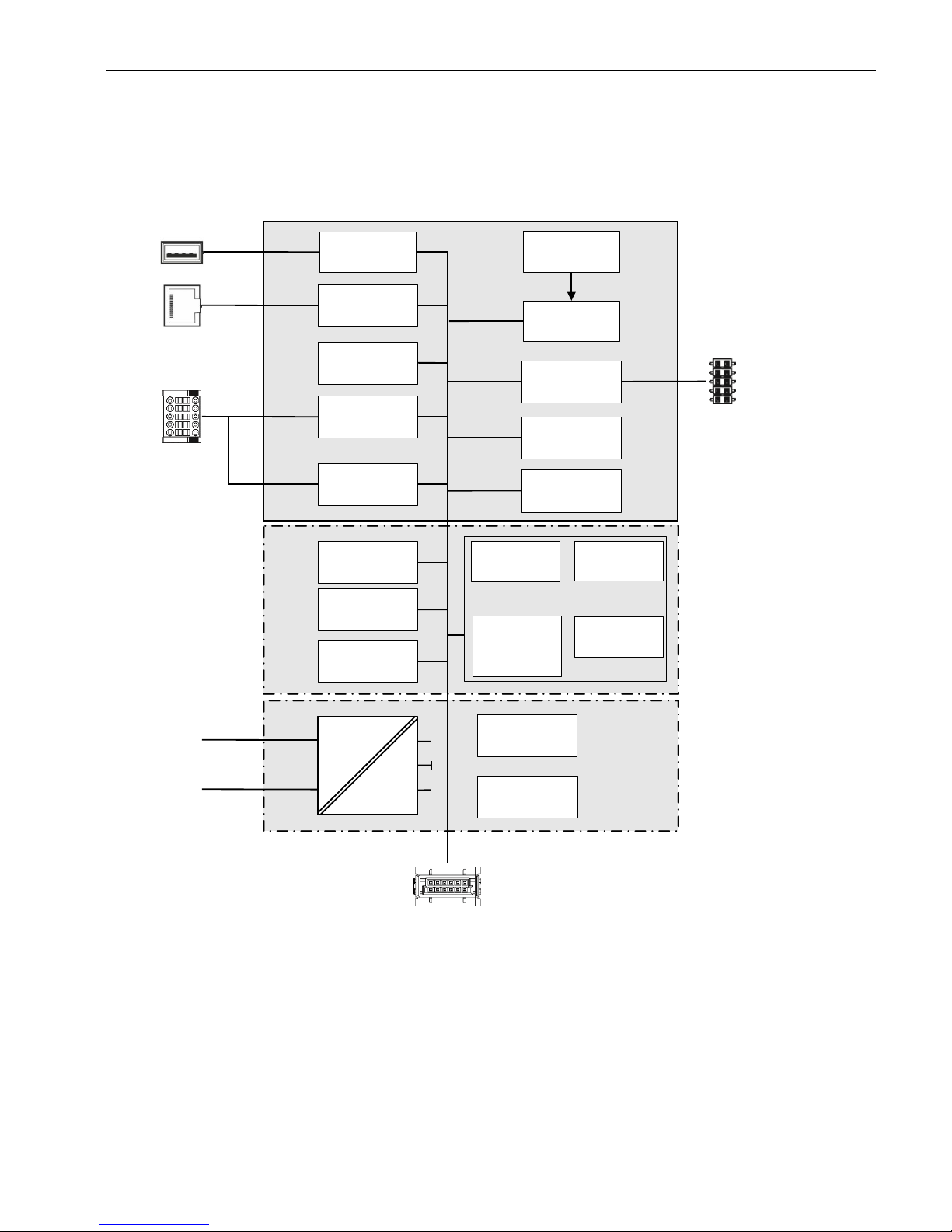
2.3. Block diagram
2VF100514DG01.vsd
Flash
RAM
Ethernet-
Controller
DC
DC
L +
L -
USB
Transceiver
Ethernet-
Transceiver
CAN
Transceiver
SIO
Transceiver
S0 +
Status-LED
EtherCAT-
Transceiver
USB
LAN
COM /
CAN
+5 V
+3,3 V
GND
Ether
CAT
CAN
SIO
CPU
EtherCAT
Ethernet /
COM / CAN
Accu
RTC
Serial
EEPROM
Retain memory
Voltage control
Energy reserve
Page 16
USER MANUAL 1.7 | EC1000
Berghof Automation GmbH | Harretstrasse 1 | 72800 Eningen | www.berghof.com
EC1000_HB_en_2D1652008ZD00.docx | 2VF100179FE06.docx
16
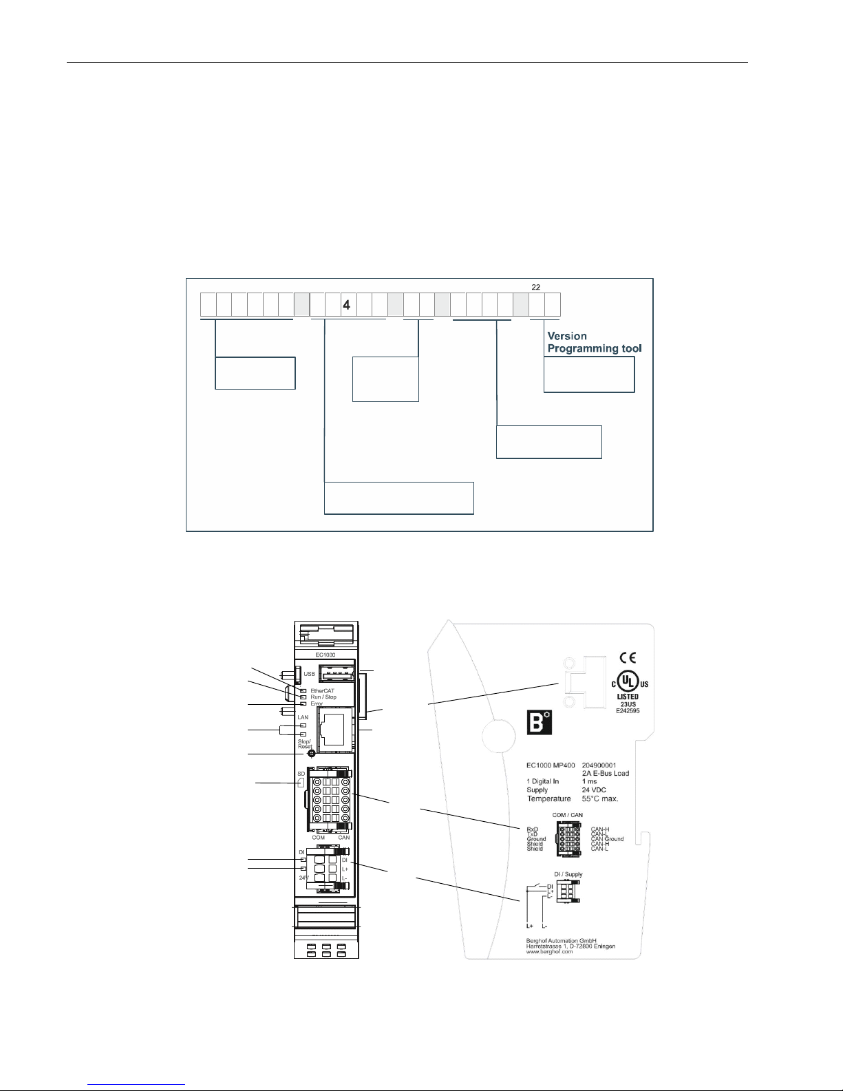
2.4. Identification
Product: Ethernet-Controller, Type EC1000
Identification code
The features of the Ethernet-Controller (see ‘Annex, Nameplate’) can be itemised according to the
identification code.
2VF100582DG00.cdr
2.5. Module view and pin assignment
2VF100515DG02.vsd
E
C 1
0 0 0
M
P
00
1 2 3 4
5 6 7 8 9 10
11 12
13
14
15
1 1 1
3
0 0
3V
16
17
18
19 20 21
23
00 = part
equipping
variant
MP400 = Power PC 400 MHz
V3 = CODESYS
Version 3.x
1131 = CODESYS
controller
EC = Ethernet-
Controller
Product
Programming tool
Processor type
Variant
EtherCAT
USB
LAN
EtherCAT
green/red
Run/Stop
red/green/yellow
Error red
LAN acitvity
Stop/Reset
Button
DI yellow
Power green
SD Card Slot
COM /
CAN
DI /
Supply
204900001
Page 17
USER MANUAL 1.7 | EC1000
Berghof Automation GmbH | Harretstrasse 1 | 72800 Eningen | www.berghof.com
2VF100179FE06.docx | EC1000_HB_en_2D1652008ZD00.docx
17
2
1
2.6. Mounting and connecting
2.6.1. Mounting
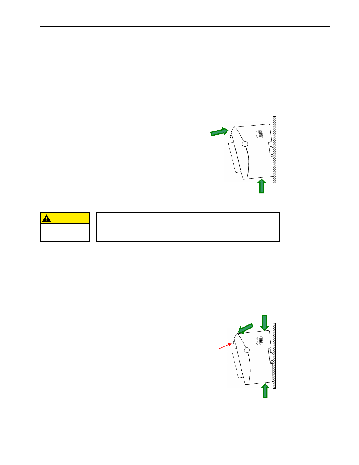
The CANtrol E-I/O modules are intended for mounting rail installation (DIN EN 60715, 35 x 7.5 mm).
Push up the module against the mounting rail from below,
allowing the metal spring to snap in between mounting
rail and mounting area as illustrated.
Push the module above against the mounting wall until it
snaps in.
Rail mounting of module
CAUTION
There must be at least 100 mm clearance above and below the EC1000.
This guarantees the necessary convection cooling for the EC1000.
The mounting plate must be metal in order to ensure heat conduction.
To interconnect two modules
After snapping on the first module to the rail, snap on the second module about 1cm away towards the right
of the first module. Push the second module along the rail towards the first module until you hear the locking
device snap in.
To disconnect two modules
Push down the unlock button (see figure below) of the module that you wish to disconnect from the module
to the left of it. Push both modules away from one another until they are about 1 cm apart.
To snap on a
single module
To take down a
single module
Push the module up and against the metal spring lo-
cated on the underside of the rail guide.
Tip the module away from the rail as shown in the il-
lustration.
Pull the module down and out of the mounting rail.
Uninstalling a module
Unlock botton
1
2
3
Page 18
USER MANUAL 1.7 | EC1000
Berghof Automation GmbH | Harretstrasse 1 | 72800 Eningen | www.berghof.com
EC1000_HB_en_2D1652008ZD00.docx | 2VF100179FE06.docx
18
2.6.2. Connecting
Power supply
The controller is energised from an external 24 VDC external power supply. Before connecting up, check that
the specifications required for the external power supply are observed.
External power supply (24 VDC)
Output voltage
+24 VDC SELV (-15 % / +20 %)
Ripple
Max. 5 %; the DC voltage must not fall short of 20.4 V.
Internal power supply unit
A power supply unit for the system electronics is installed to provide 24-VDC input voltage (-15 % / +20 %).
The power supply unit possesses integrated polarity-reversal protection and inrush-current limitation.
Both supply lines and the power supplies must be protected by an external short circuit and overload protection with a maximal tripping current of 5 A in each case (depending on the number of I/O).
Installation
All connections and lines must be executed so that no faults are caused by inductive and capacitive interference in the controller. The supply lines must be sufficiently resilient to current and voltage. Shielded lines
must be used for communication. The shield must be fitted onto the module.
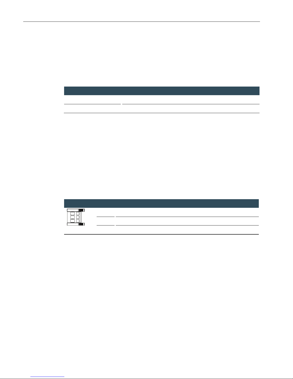
Plug DI/Supply assignment
DI/Supply
DI
Digital input 24 VDC (-20 % / +25 %)
L+
External power supply 24 VDC (-15 % / +20 %)
L-
External power supply GND
Energy buffering
Power Fail 10 ms depending on compliance with the max. number/load by I/O modules.
Page 19
USER MANUAL 1.7 | EC1000
Berghof Automation GmbH | Harretstrasse 1 | 72800 Eningen | www.berghof.com
2VF100179FE06.docx | EC1000_HB_en_2D1652008ZD00.docx
19
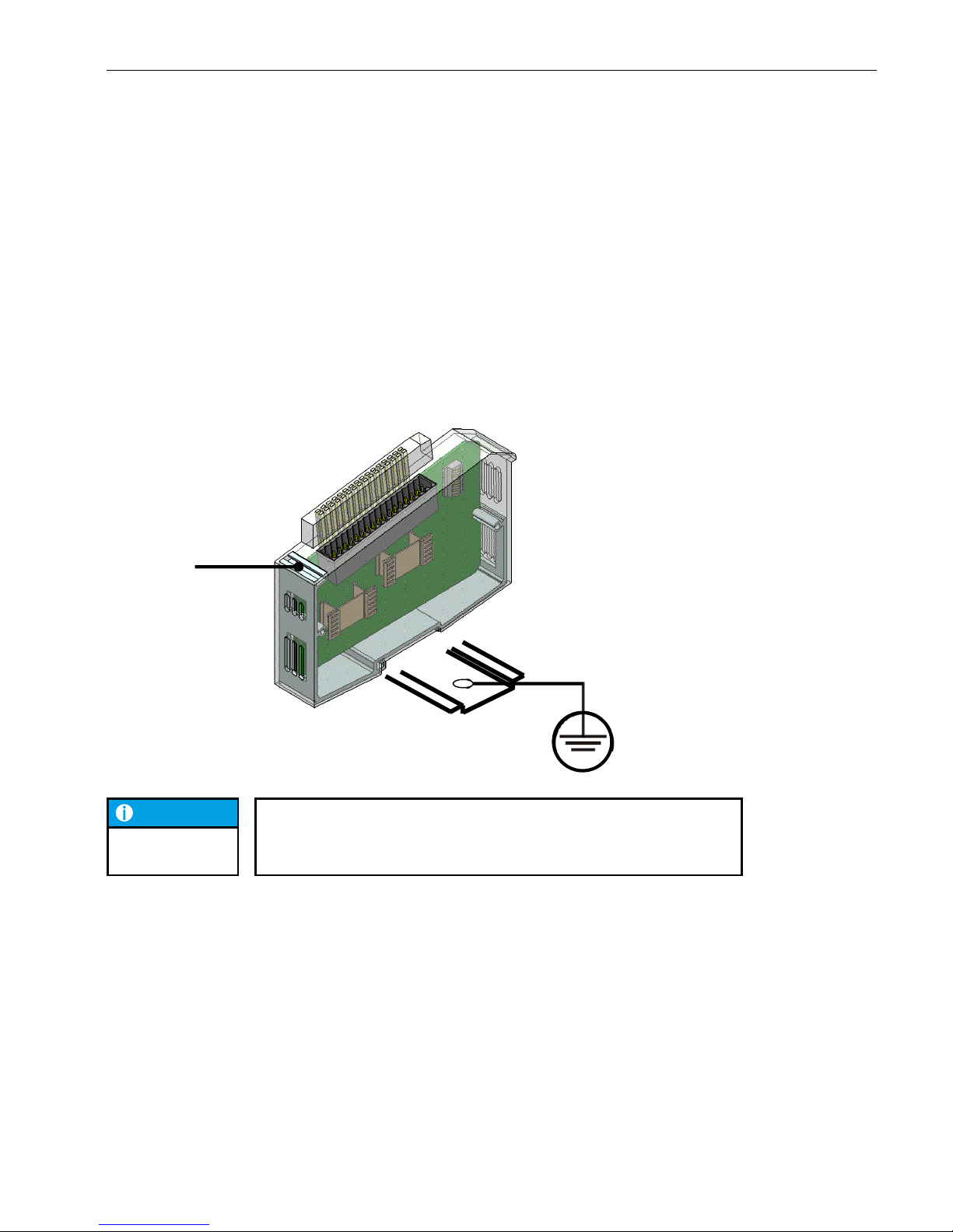
2.6.3. Earth
Connect the EC1000 to earth by attaching the metal housing to operative earth.
Since the operative earth connectors dissipate HF currents, it is of utmost importance for the module's noise
immunity. HF interference is dissipated from the electronics board to the metal housing. The metal housing
therefore needs to be suitably connected to an operative earth connector.
You will normally have to ensure that
the connection between module housing and DIN rail conducts well,
the connection between DIN rail and switching cabinet conducts well,
the switching cabinet is safely connected to earth.
In special cases you may attach the earth wire straight to the module.
NOTICE
Earth wires should be short and have a large surface (copper mesh).
Further details has site http://en.wikipedia.org/wiki/Ground (electricity).
Aluminium profile
Attach cable shield here
Connect DIN rail with operative
earth
M3x5 Bolt connection
Page 20
USER MANUAL 1.7 | EC1000
Berghof Automation GmbH | Harretstrasse 1 | 72800 Eningen | www.berghof.com
EC1000_HB_en_2D1652008ZD00.docx | 2VF100179FE06.docx
20
2.7. Pin assignment
2.7.1. 10/100 Base-T network connection (Ethernet)
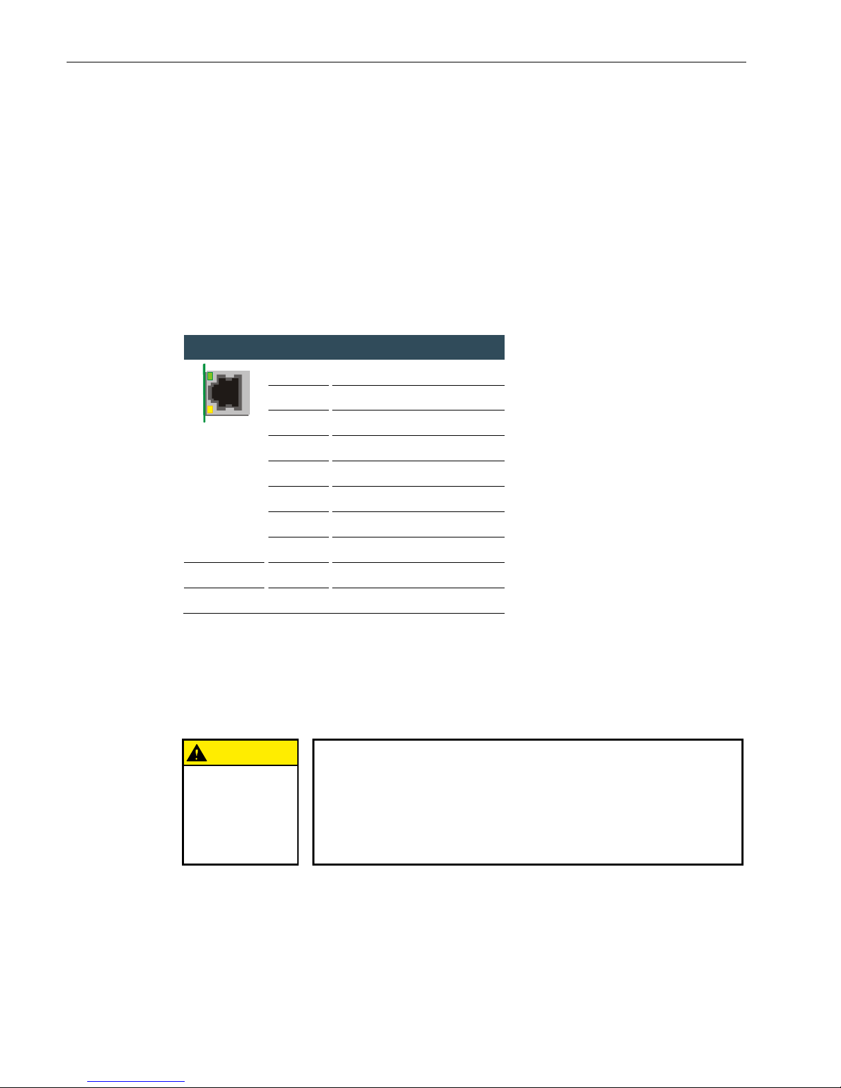
The 10/100 Base-T on board Ethernet adapter with RJ-45 connection enables connection to the network.
The “LNK” and “RCV” status LED give information about successful connection to the network in compliance
with IEEE 802.3, clause 25.
LAN plug-in connector assignment
LAN
RJ45
1
TX+ 2 TX-
3
RX+
4
75 Ohm
5
75 Ohm
6
RX-
7
75 Ohm
8
75 Ohm
“LNK” LED
green
ON: ready to operate
“RCV” LED
yellow
FLASHING: Data Receive
2.7.2. USB
Devices with USB interfaces can be connected on the USB master port (rev. 1.1). The only classes of USB devices which can be used by CODESYS users are USB sticks. A mouse can only be used at the level of Linux.
The following issues must be taken into account when using USB sticks:
CAUTION
A USB stick may only be unplugged during operation if all file operations
have been completed, otherwise the USB may become unserviceable!
If programs still have files open, the directory cannot be deleted when the USB
stick is removed. In this situation file or directory operations cause blockages
because a reading must be taken from a device which is no longer available in
the system. Therefore, when removing the USB stick, always make sure that
no program has any files still open on the USB stick.
Connection to the
network
Page 21
USER MANUAL 1.7 | EC1000
Berghof Automation GmbH | Harretstrasse 1 | 72800 Eningen | www.berghof.com
2VF100179FE06.docx | EC1000_HB_en_2D1652008ZD00.docx
21
USB memory sticks can be plugged in and removed during operation. The plugged-in device is auto-
matically identified and mounted in the /media/usbX directory. When the USB stick is unplugged, the
relevant /media/usbX directory automatically “vanishes” again, if it is no longer being accessed by a
program (see above).
Either the first partition or – if there is no partition – the entire memory is mounted on the memory
stick, i.e. it appears automatically in the appropriate directory.
The first stick is mounted under /media/usb0, the second under /media/usb1, etc. Maximally 8 sticks
can be plugged in and used at once (/media/usb [0-7]. If a new stick is plugged in (or one which has
previously been plugged in and then removed), it will be placed in the directory with the lowest free
number. By connecting an USB hub it is possible to operate multiple sticks on one USB interface. In
this case attention must be paid that there are no USB devices still attached to the hub itself when it is
plugged in and unplugged.
NOTICE
The mechanical structure of the USB port is designed for max. 1,000 mating
cycles.
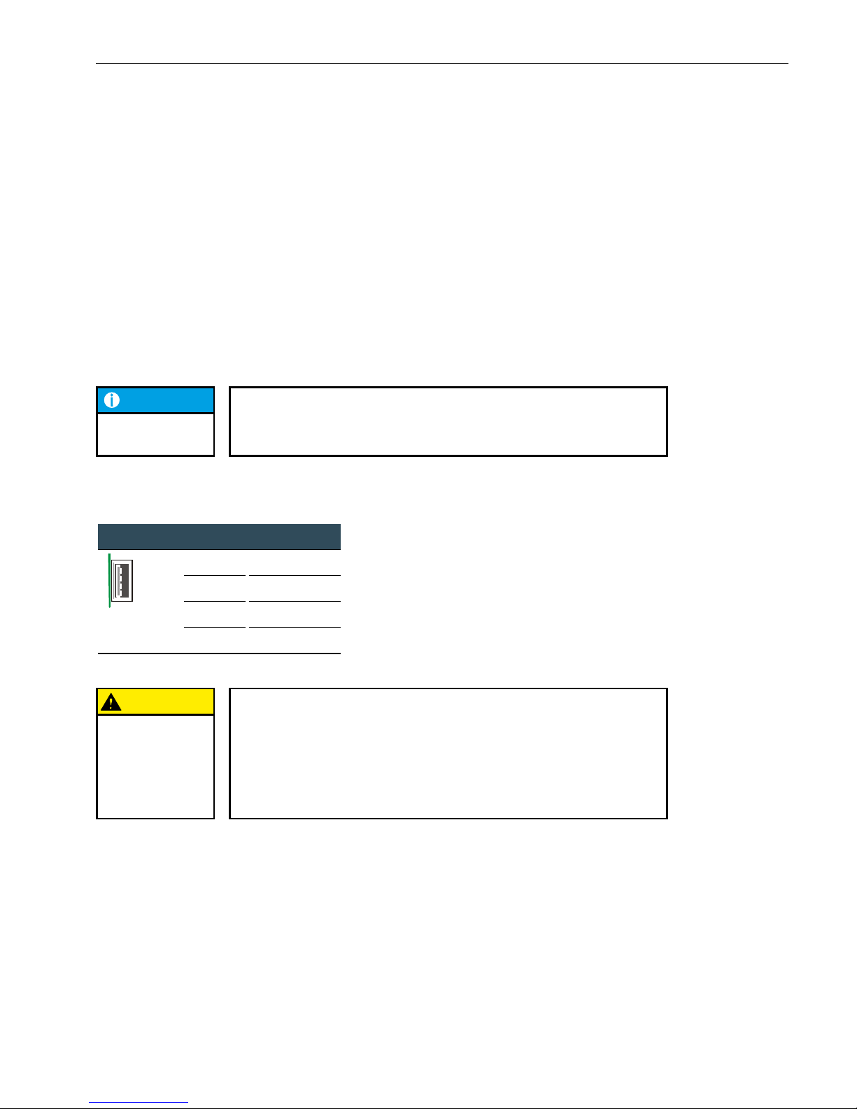
USB plug assignment
USB
USB
B1
VCC
B2
D-
B3
D+
B4
GND
CAUTION
The maximum current available on the USB port is 0.5 A! Before you use
the USB device, check its power consumption.
The controller performs a reset if a USB device requires more than the max.
permissible current. A reset immediately stops the controller and the machine
and plant it controls. This may cause more extensive damage.
A USB device requiring more current cannot function and may be damaged by
this.
Page 22
USER MANUAL 1.7 | EC1000
Berghof Automation GmbH | Harretstrasse 1 | 72800 Eningen | www.berghof.com
EC1000_HB_en_2D1652008ZD00.docx | 2VF100179FE06.docx
22
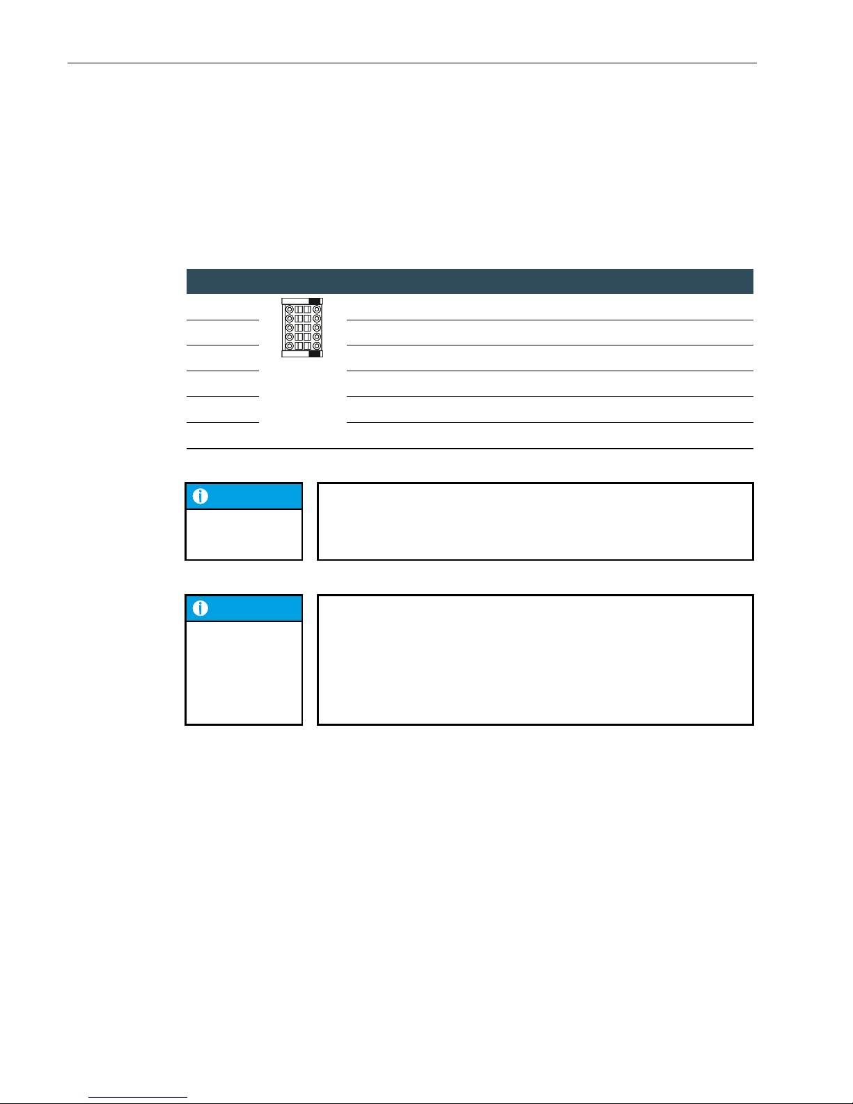
2.7.3. CAN bus and serial interface
The CAN interface conforms to the ISO 11898 standard and can be operated up to the maximum baud rate of
1 Mbit/s. The lowest baud rate which can be set is 50 kBit/s.
COM/CAN plug assignment:
COM/CAN
RS232
COM/CAN
CAN-Bus
RxD
CAN-H
TxD
CAN-L
Ground
CAN Ground
Shield
CAN-H
Shield
CAN-L
NOTICE
A 120 Ω terminal resistor can be connected between the CAN_L and
CAN_H connections.
This is necessary if the appropriate CAN interface is located at the beginning or
end of the relevant CAN bus topology.
NOTICE
The RS232 interface X3 has an exceptional position!
Depending on the configuration, it can be used either as a Linux console, or as
a PPP interface for remote maintenance, or as a CODESYS programming interface.
If the controller is started in the configuration mode, the module can be configured via a serial PPP connection in this mode. Here, too, the connection is made
via X3.
The serial interface is addressed in the software under the name of COM1.
Page 23
USER MANUAL 1.7 | EC1000
Berghof Automation GmbH | Harretstrasse 1 | 72800 Eningen | www.berghof.com
2VF100179FE06.docx | EC1000_HB_en_2D1652008ZD00.docx
23
2.7.4. EtherCAT
The EC1000 PLC controller can be extended by means of a system of EtherCAT I/O modules (E-I/O). The EI/O modules which are lined up on the side to the right are designed for connecting diverse process signals
(refer to the EtherCAT I/O manual).
At the same time the EC1000 assumes the function of the PLC controller and an EtherCAT bus coupler.
Therefore, the conversion of the EtherCAT communication signals to the LVDS (E-bus) transmission physics
takes place internally. As the EtherCAT Master the EC1000 sends frames for writing the output data and for
reading the input data. The Ethernet EtherCAT protocol is retained right down to the very last I/O module by
this method. At the end of the modular device the connection of the outward and return line is made automatically.
Furthermore, the system voltage of the connected I/O modules is generated in the EC1000. While this simplifies the connection of the I/O modules on the one hand, on the other hand the maximum number of I/O
modules which can be connected has to be taken into account.
An extender module facilitates the connection of further EtherCAT Slaves to the EC1000.
CAUTION
The number of connectable EtherCAT I/O modules is limited!
Each EtherCAT I/O module produces a so-called “E-bus load" load. This is
what the power load is called which is required to supply the electronics inside
the device. The EC1000 supplies current up to 2 A for the purpose. This means
that, at most, one EC1000 can supply maximally 10 I/O modules.
Status display LED
The EtherCAT LED indicates the status of the EtherCAT ASICs.
EtherCAT
Status
LED, flash code
Meaning
Init
Red, continuous light
Intialisation status, no data exchange
Pre-Op
Red/Green, 1:1
Preoperational status, no data exchange
Safe-Op
Red/Green, 3:1
Safe operational status, inputs can be read
Op
Green, Continuous light
Operational status, full data exchange
PLC controller
System voltage
Page 24
USER MANUAL 1.7 | EC1000
Berghof Automation GmbH | Harretstrasse 1 | 72800 Eningen | www.berghof.com
EC1000_HB_en_2D1652008ZD00.docx | 2VF100179FE06.docx
24
2.7.5. SD Card
WARNING
While the EC1000 is in operation the SD card may not be inserted or removed, otherwise the functions of the EC1000 may be impaired!
The SD card may only be inserted when the EC1000 is de-energised!
The compact SD card drive is equipped with a push-in/push-out insertion and ejection mechanism.
Gold-plated contacts guarantee low contact resistances and a service life of 10,000 push-in cycles.
At present the write protection switch on the SD card is not identified.
The SD card drive has to be activated via the web configuration.
The files on the SD drive can be written, read and copied.
The drive can be accessed via the following path: /media/sd.
At present data memory cards with a memory capacity of up to 1 GB can be used.
Page 25
Berghof Automation GmbH | Harretstrasse 1 | 72800 Eningen | www.berghof.com
2VF100180FE04.docx | EC1000_HB_en_2D1652008ZD00.docx
25
3. Controller operation
CAUTION
Never plug in, apply, disconnect or touch connections while the device is
operating!
This could result in malfunction or destruction of the device. Before working on
the modules, always switch all infeeds to them off; including infeeds from connected peripheral devices such as remote-feed encoders, programming devices, etc.
MALFUNCTION
3.1. Commissioning
Before applying the supply voltage, recheck all connections to ensure they are properly wired and have the
correct polarity.
Switching on
The module is not equipped with its own main power switch. The PLC controller starts when the associated
equipment is switched on or when the power supply is connected.
Switching off
The PLC controller switches off when the associated equipment is switched off or the power supply is disconnected.
3.2. Function Selection, Indicators, Diagnostics
3.2.1. Status Indicators
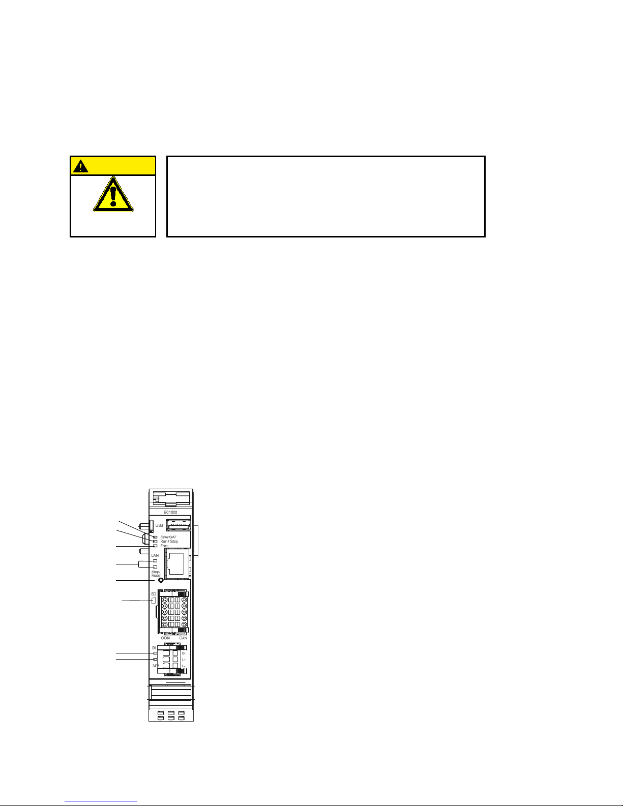
The function of the status indicators frequently depends on the software development environment
employed on the PLC controller.
CP1131-P:
PLC programming using CODESYS and
Berghof Target Support Package.
CPC++:
C programming directly on the LINUX operating
system.
from 2VF100515DG02.vsd
EtherCAT
green/red
Run/Stop
red/green/yellow
Error red
LAN acitvity
Stop/Reset
Button
DI yellow
Power green
SD Card Slot
204900001
Page 26
Berghof Automation GmbH | Harretstrasse 1 | 72800 Eningen | www.berghof.com
EC1000_HB_en_2D1652008ZD00.docx | 2VF100180FE04.docx
26
Power LED
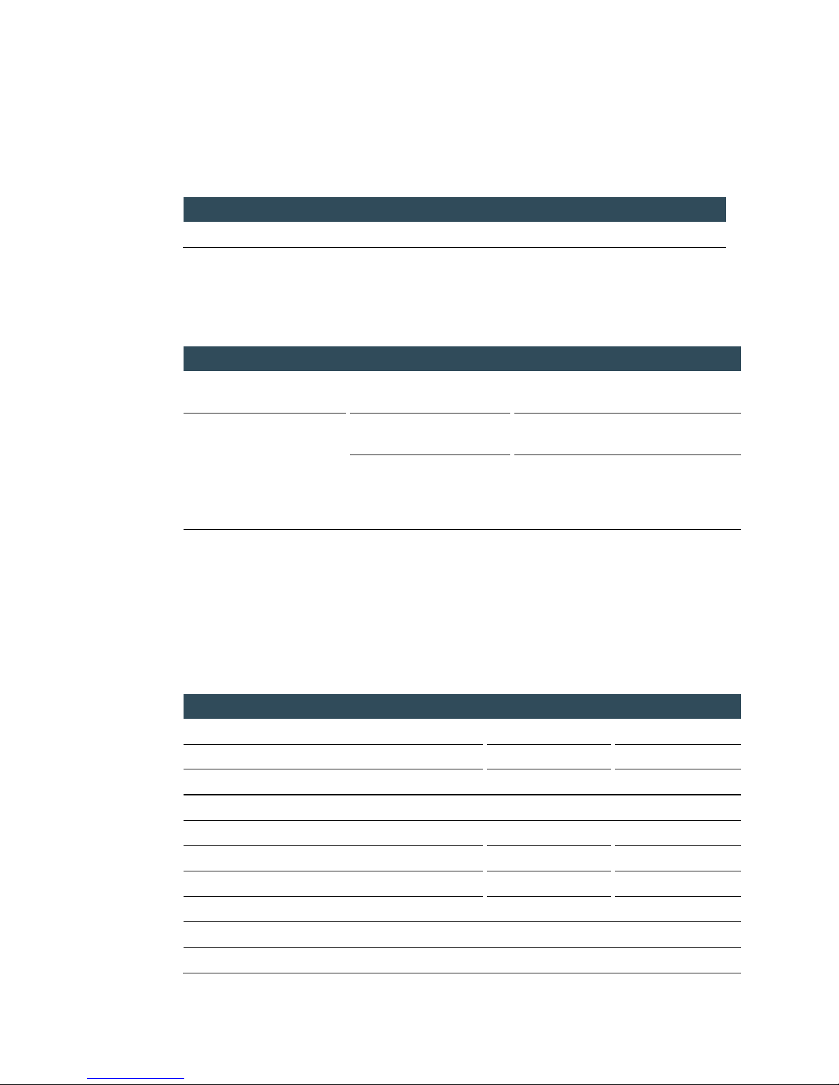
4 operating status LED indicate the current status of the voltage supply, module mode and error messages.
LED
Logical status
1
PWR (green)
ON = correct voltage supply to the module electronics
RUN/STOP BUTTON
The Run/Stop control button replaces the former control switch.
This slightly changes the operating concept:
Action
Command
Submarine, boot phase
Activation of the pushbutton
Change into PPP mode or submarine
console
CODESYS PLC/ CP1131-P
Short push
Change between RUN and STOP mode
of PLC
Long push
STOP the PLC using RESET of the variables, but not the retain data (corresponding to the activation of the rocker switch
on the DC1000 modules)
It is then no longer possible to force-hold the PLC controller in the STOP state!
LEDs: RUN/STOP ERROR - LED signalisation
2 LED are available on the module to signalise the system status (RUN/STOP in two colours:
red/green/(yellow); ERROR in red only). The flash codes familiar from the DC1000 are therefore no longer
applicable. The following system states are signalised via the LED:
System states
LED RUN/STOP
LED ERROR
PPP configuration mode active
Yellow
Off
USB packet update active
Yellow, flashing
Off
System error
Off
On
PLC states
RUN
Green
Off
STOP
Red
Off
Error stop
Red
On
Reset button registered
Red, flashing
Off
Applicatory states
Identification of ProfiNET device
Yellow, flashing
Flash
Page 27
Berghof Automation GmbH | Harretstrasse 1 | 72800 Eningen | www.berghof.com
2VF100180FE04.docx | EC1000_HB_en_2D1652008ZD00.docx
27
Basic procedure in case of error stop:
Establish cause of error (read via web browser)
Eliminate cause of error
Perform reset on controller, alternatively: Mode selector switch / CODESYS / web browser
Put controller back into operation
NOTICE
CP1131-P mode FORCE:
FORCE means that the user program is running and at least one variable is
compulsorily attributed via CODESYS at the beginning of each cycle. The user
can therefore see that without this intervention in the sequence of the PLC program the user program might react differently.
Status LED for CPC++ programs
The LED can be controlled by user software.
Ethernet status LED
Refer to section: 10/100 Base-T network connection (Ethernet).
3.3. Real-Time Clock with Backup Battery
The EC1000 is equipped with a real-time clock.
Setting the clock
Use either the web configuration or the CODESYS “BGHSysLibRtc.lib” library.
Power supply
A rechargeable battery is incorporated to energise this clock.
Changing the rechargeable battery
There is no need for the user to change the battery.
NOTICE
The battery must be changed expertly by the manufacturer of the module.
Type of rechargeable battery
Panasonic VL2020 or equivalent.
Battery service life
typ. 10 years depending on temperature in use.
Battery storage
> 1 year voltage-free; thereafter the data of the RTC may possibly be lost.
Page 28
Berghof Automation GmbH | Harretstrasse 1 | 72800 Eningen | www.berghof.com
EC1000_HB_en_2D1652008ZD00.docx | 2VF100180FE04.docx
28
Battery transport
The VL2020 Accu is permanently installed in the device. The battery contains 0.01g lithium.
NOTICE
The devices contain lithium-ion batteries of the Panasonic manufacturer.
They are classified in UN 3091.
For further information look in the PSDS to be found under
https://industrial.panasonic.com/ww/downloads/psds.
TRANSPORT
Page 29
Berghof Automation GmbH | Harretstrasse 1 | 72800 Eningen | www.berghof.com
2VF100227FE04.docx | EC1000_HB_en_2D1652008ZD00.docx
29
4. Annex
4.1. Environmental Protection
4.1.1. Emission
When used correctly, our modules do not produce any harmful emissions.
4.1.2. Disposal
At the end of their service life, modules may be returned to the manufacturer against payment of an allinclusive charge to cover costs. The manufacturer will then arrange for the modules to be recycled.
4.2. Maintenance/Upkeep
WARNING
Do not insert, apply, detach or touch connections while in operation –
risk of destruction or malfunction.
Disconnect all incoming power supplies before working on our modules; this
also applies to connected peripheral equipment such as externally powered
sensors, programming devices, etc. All ventilation openings must always be
kept free of any obstruction.
The modules are maintenance-free when used correctly.
Clean only with a dry, non-fluffing cloth.
Do not use detergents!
4.3. Repairs/Service
WARNING
Repair work may only be carried out by the manufacturer or its authorised service engineers.
4.3.1. Warranty
Sold under statutory warranty conditions. Warranty lapses in the event of unauthorised attempts to repair
the equipment and/or product, or in the event of any other form of intervention.
Page 30
Berghof Automation GmbH | Harretstrasse 1 | 72800 Eningen | www.berghof.com
EC1000_HB_en_2D1652008ZD00.docx | 2VF100227FE04.docx
30
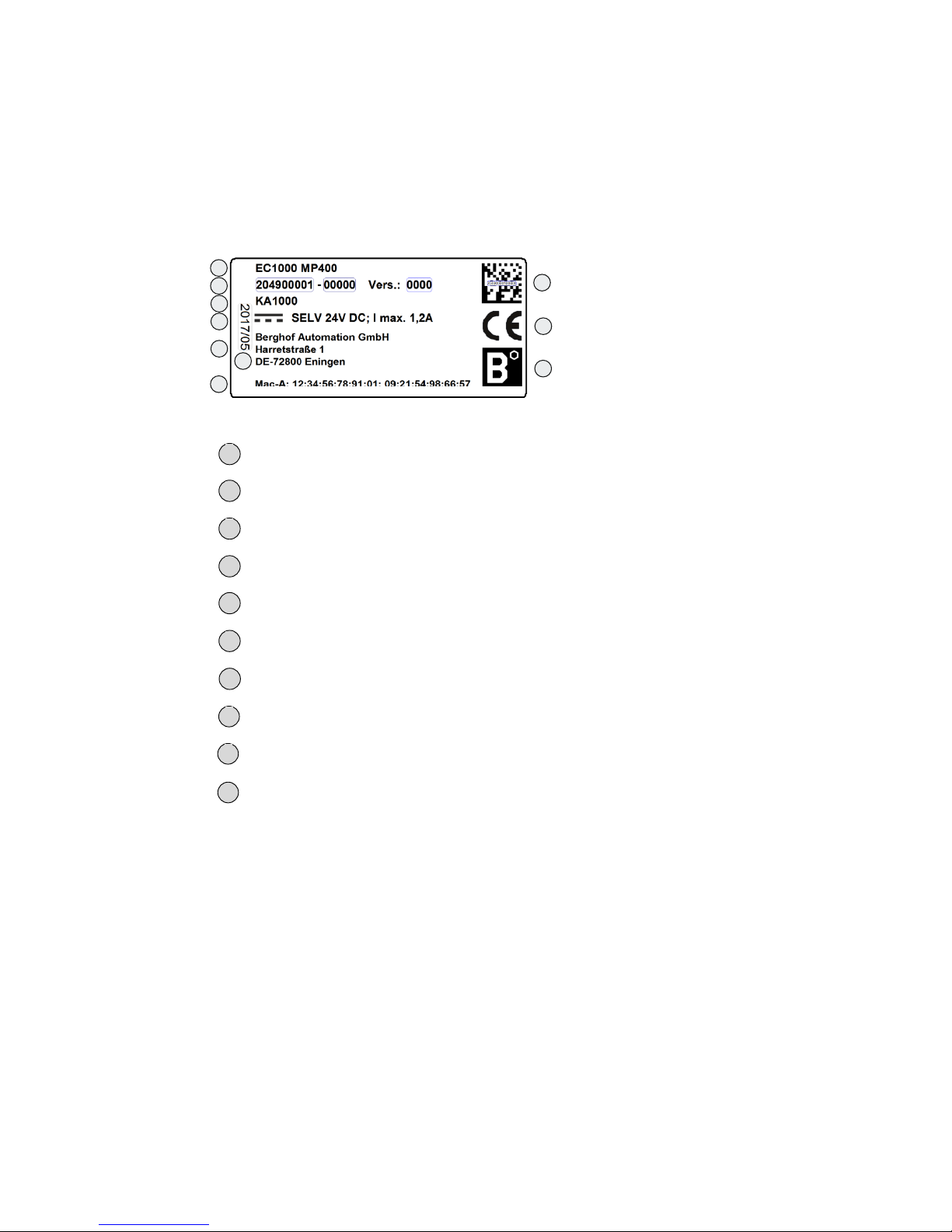
4.4. Nameplate
Nameplate descriptions (example)
1
2
3
4
5
6
8
9
10
7
2VF100080DG04.cdr
Designation of device type
Identification no. (item no. + serial no.)
Customer no.
Supply voltage
Manufacturer’s address
Mac addresses
Production date
QR code (identification no.)
CE marking
Brand of the manufacturer (trademark)
1 2 3 4 5 6 7 8 9
10
Page 31

Berghof Automation GmbH | Harretstrasse 1 | 72800 Eningen | www.berghof.com
2VF100227FE04.docx | EC1000_HB_en_2D1652008ZD00.docx
31
4.5. Addresses and Bibliography / Standards
4.5.1. Addresses
CAN in Automation; international manufacturers and users organisation for CAN users in the field of automation:
CAN in Automation e.V. (CiA)
Am Weichselgarten 26
D-91058 Erlangen / Germany
[email protected]
www.can-cia.de
EtherCAT Technology Group
ETG Headquarters
Ostendstraße 196
D-90482 Nuremberg / Germany
[email protected]
www.ethercat.org
Beuth Verlag GmbH, 10772 Berlin
or
VDE-Verlag GmbH, 10625 Berlin
VDE Verlag GmbH, 10625 Berlin
or
Internet search: www.iec.ch
CiA
ETG
DIN-EN
Standards
IEC Standards
Page 32

Berghof Automation GmbH | Harretstrasse 1 | 72800 Eningen | www.berghof.com
EC1000_HB_en_2D1652008ZD00.docx | 2VF100227FE04.docx
32
4.5.2. Bibliography / Standards
Standard
Label
IEC61131-1 / EN61131-1
Programmable controllers
Part 1: General information
IEC61131-2 / EN61131-2
Programmable controllers
Part 2: Equipment requirements and tests
IEC61131-3 / EN61131-3
Programmable controllers
Part 3: Programming languages
IEC61131-4 / EN61131Bl1
Programmable logic controllers
Supplementary Sheet 1: User guidelines
IEC61000-6-4 / EN61000-6-4
German EMC Standard: Emitted interference
IEC61000-6-2 / EN61000-6-2
German EMC Standard: Noise immunity
ISO/DIS 11898
Draft International Standard:
Road vehicles - Interchange of digital information - Controller Area
Network (CAN) for high-speed communication
DIN EN ISO 13849-1
Safety of machinery:
Safety-related parts of control systems (Part 1)
UL 508
Industrial Control Equipment
17 th edition / 1999-01-28
EN 50581
Technical documentation for the assessment of electrical and electronic products with respect to the restriction of hazardous substances
Notice: Our Technical Support team will be glad to provide other literature references on request.
 Loading...