

Page 1
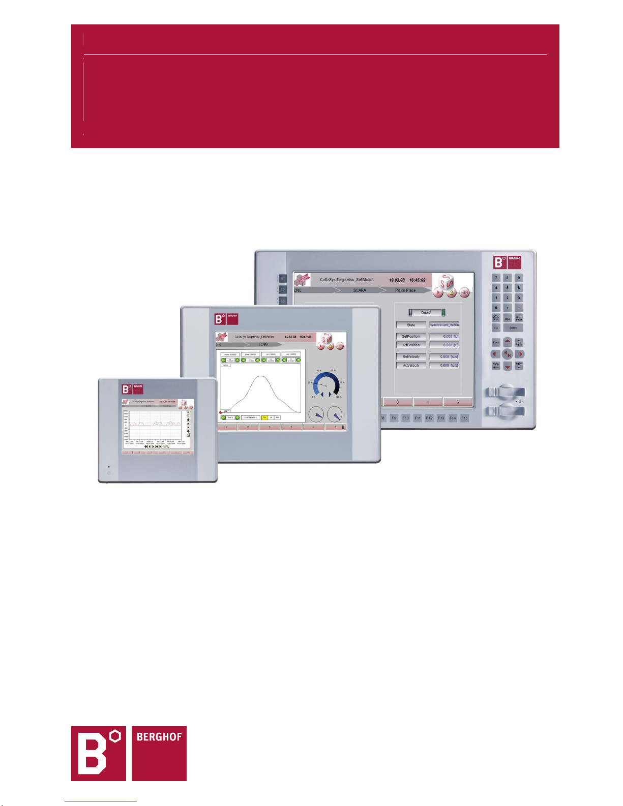
USER MANUAL 1.10
DC1000 Dialog-Controller
Basic, Prime, Compact, Clean
Page 2

Copyright © Berghof Automation GmbH
Reproduction and duplication of this document and utilisation and communication of its content is
prohibited, unless with our express permission. All rights reserved. Damages will be payable in case of infringement.
Disclaimer
The content of this publication was checked for compliance with the hardware and software described. However, discrepancies may arise, therefore no liability is assumed regarding complete compliance. The information in this document will be checked regularly and all necessary corrections will be included in subsequent editions. Suggestions for improvements are always welcome.
Subject to technical changes.
Trademarks
CANtrol® and CANtrol®- dialog are registered trademarks of Berghof Automation GmbH
Microsoft®, Windows® and the Windows® Logo are registered trademarks of Microsoft Corporation in
the USA and other countries.
EtherCAT® is a registered trademark and patented technology, licensed from Beckhoff Automation
GmbH, Germany.
CiA® and CANopen® are registered community trademarks of CAN in Automation e.V.
All rights reserved by the individual copyright holders.
General Information on this Manual
This equipment manual contains product-specific information valid at the time of publication.
This equipment manual is only complete in conjunction with the product-related hardware and software user
manuals required for the individual application.
You can reach us at:
Berghof Automation GmbH
Harretstr. 1
72800 Eningen
Germany
T +49.7121.894-0
F +49.7121.894-100
e-mail: [email protected]
www.berghof.com
Berghof Automation GmbH works in accordance with DIN EN ISO 9001:2000.
Content
Completeness
Page 3
USER MANUAL 1.10 | DC1000 DIALOG-CONTROLLER
Berghof Automation GmbH | Harretstrasse 1 | 72800 Eningen | www.berghof.com
DC1000_HB_en_2D0982010ZD00.docx
3
Update
Version
Date
Subject
1.1
22.09.2006
First version
1.2 Inexistent
1.3
31.05.2007
Dimensions updated under “Technical specifications” and in the graphs.
Plug/unplug cycles added to the “USB pin assignment” section of the “Tech-
nical specifications”. Description, “Chemical resistance for touch screens
and I/O-Modules” included.
Notice to “SD-card reader” included. Update under “Power supply - internal
power pack”, “Profibus master card” and “Profibus slave card”.
1.4
23.09.2009
General revision.
New chapter: “Copyright and software licenses”.
1.5
28.10.2009
Supplement of technical data for DC 1005, 1010 and 1012.
Update of “Service Menu” chapter.
1.6 Inexistent
1.7
07.04.2011
Updates of “Declaration of conformity”, “Chemical resistance” and “Notes on
the copyright and software license”. Description of DC1010 Compact (CP)
and DC1012 Compact (CP) incorporated, XR01 and XR02 extension modules inserted.
“Battery change” diagram corrected.
Corrections of the DC1010 (CP) “Panel cut-out”, DC1012 “Technical data”
(dimensions), new warning for XR01 and XR02 I/O cards (power supply) integrated.
1.8
08.11.2012
Update in the “Declaration of conformity” section.
Note on terminating resistors, switches S2+S3 with Profibus Master/Slave
card inserted.
Update of chapter “Annex, Standards / Bibliography”.
Update of the trademarks.
Update in the “DC1010 Compact (CP) panel cutout” section.
1.9
04.09.2013
Transition into new CD.
New corporate name “Berghof Automation GmbH”.
Update of chapter “Extension modules”.
1.10
03.05.2016
New EMC directive.
Correction standards.
Update of chapter “Chemical resistance”.
Update of section “Nameplate”.
Page 4

USER MANUAL 1.10 | DC1000 DIALOG-CONTROLLER
Berghof Automation GmbH | Harretstrasse 1 | 72800 Eningen | www.berghof.com
DC1000_HB_en_2D0982010ZD00.docx
4
Blank page
Page 5

USER MANUAL 1.10 | DC1000 DIALOG-CONTROLLER
Berghof Automation GmbH | Harretstrasse 1 | 72800 Eningen | www.berghof.com
DC1000_HB_en_2D0982010ZD00.docx
5
Contents
1. GENERAL ............................................................................................................................................ 9
1.1. About this manual .............................................................................................................................. 9
1.2. Hazard categories and terminology ................................................................................................ 10
1.3. Qualified personnel .......................................................................................................................... 11
1.4. Due diligence .................................................................................................................................... 11
1.5. Basic safety measures ..................................................................................................................... 12
1.6. Use as prescribed ............................................................................................................................ 13
1.7. Conformity declaration .................................................................................................................... 14
1.7.1. Extension modules ............................................................................................................................. 14
1.8. Transport and setup ......................................................................................................................... 15
2. PRODUCT DESCRIPTION ................................................................................................................ 17
2.1. Identification ..................................................................................................................................... 19
2.2. The different versions of the Dialog-Controller ............................................................................. 20
2.2.1. Interfaces ........................................................................................................................................... 20
2.2.2. Front foil sheeting ............................................................................................................................... 20
2.2.3. Overview of types ............................................................................................................................... 21
2.2.4. Variable thanks to extension cards ..................................................................................................... 21
2.3. Dialog-Controller DC1005 / DC1010 / DC1012 construction ........................................................ 22
2.3.1. Block circuit diagram .......................................................................................................................... 22
2.4. Technical data DC1005 .................................................................................................................... 23
2.4.1. DC1005 Front view ............................................................................................................................. 25
2.4.2. DC1005 Rear view ............................................................................................................................. 25
2.4.3. DC1005 Dimensions .......................................................................................................................... 26
2.4.4. DC1005 Panel cutout ......................................................................................................................... 27
2.4.5. Mounting regulation DC1005 .............................................................................................................. 27
2.5. Technical data DC1010 .................................................................................................................... 28
2.5.1. DC1010 Front view ............................................................................................................................. 30
2.5.2. DC1010 Rear view ............................................................................................................................. 30
2.5.3. DC1010 Dimensions .......................................................................................................................... 31
2.5.4. DC1010 Panel cutout ......................................................................................................................... 32
2.5.5. Mounting regulation DC1010 .............................................................................................................. 32
2.6. Technical data DC1010 Compact (CP) ................................ ............................................................ 33
2.6.1. DC1010 Compact (CP) front view ...................................................................................................... 35
2.6.2. DC1010 Compact (CP) rear view ................................ ....................................................................... 35
2.6.3. DC1010 Compact (CP) dimensions ................................................................................................... 36
2.6.4. DC1010 Compact (CP) panel cutout .................................................................................................. 37
2.6.5. Mounting regulation DC1010 Compact (CP) ...................................................................................... 37
2.7. Technical data DC1012 .................................................................................................................... 38
2.7.1. DC1012 Front view ............................................................................................................................. 40
2.7.2. DC1012 Rear view ............................................................................................................................. 40
2.7.3. DC1012 Dimensions .......................................................................................................................... 41
2.7.4. DC1012 Panel cutout ......................................................................................................................... 42
Page 6

USER MANUAL 1.10 | DC1000 DIALOG-CONTROLLER
Berghof Automation GmbH | Harretstrasse 1 | 72800 Eningen | www.berghof.com
DC1000_HB_en_2D0982010ZD00.docx
6
2.7.5. Mounting regulation DC1012 .............................................................................................................. 42
2.8. Technical data DC1012 Compact (CP) ................................ ............................................................ 43
2.8.1. DC1012 Compact (CP) front view ...................................................................................................... 45
2.8.2. DC1012 Compact (CP) rear view ....................................................................................................... 45
2.8.3. DC1012 Compact (CP) dimensions ................................................................................................... 46
2.8.4. DC1012 Compact (CP) panel cutout .................................................................................................. 47
2.8.5. Mounting regulation DC1012 Compact (CP) ...................................................................................... 47
2.9. Mounting and connection ................................................................................................................ 48
2.9.1. Mounting ............................................................................................................................................ 48
2.9.2. Connections ....................................................................................................................................... 48
2.10. Pin assignment ................................................................................................................................. 49
2.10.1. Pin overview ....................................................................................................................................... 49
2.10.2. Power supply ...................................................................................................................................... 49
2.10.3. 10/100 Base-T Network Connection (Ethernet) .................................................................................. 49
2.10.4. USB .................................................................................................................................................... 50
2.10.5. CAN bus ............................................................................................................................................. 51
2.10.6. Serial ports ......................................................................................................................................... 52
2.10.7. E-bus .................................................................................................................................................. 55
2.10.8. Connections for expansion ports ........................................................................................................ 55
2.11. SD card .............................................................................................................................................. 56
3. DIALOG-CONTROLLER OPERATION ............................................................................................. 57
3.1. Commissioning ................................................................................................................................ 57
3.2. Function selection, indicators, diagnostics ................................................................................... 57
3.2.1. Status indicators ................................................................................................................................. 57
3.3. Service menu .................................................................................................................................... 59
3.3.1. Using the service menu ...................................................................................................................... 60
3.3.2. Parameter window .............................................................................................................................. 60
“Config” service menu ........................................................................................................................ 61
“PLC” service menu ............................................................................................................................ 64
“INFO” service menu .......................................................................................................................... 65
“Display” service menu ....................................................................................................................... 66
3.3.3. PLC window ....................................................................................................................................... 67
3.4. Decommissioning ............................................................................................................................ 70
3.4.1. Disposal ............................................................................................................................................. 70
3.5. Maintenance...................................................................................................................................... 71
3.6. Help in case of problems ................................................................................................................. 71
4. EXTENSION MODULES .................................................................................................................... 73
4.1. I/O card with SC-CAN interface ....................................................................................................... 74
4.1.1. Technical data .................................................................................................................................... 75
4.1.2. Pin assignment ................................................................................................................................... 77
4.1.3. Analog inputs ..................................................................................................................................... 81
4.1.4. Digital inputs/outputs 12/4/8-0.5 ......................................................................................................... 82
4.1.5. Digital inputs, positive switched .......................................................................................................... 83
4.1.6. Digital outputs, positive switched........................................................................................................ 86
4.1.7. Digital input/output pin assignments ................................................................................................... 89
Page 7

USER MANUAL 1.10 | DC1000 DIALOG-CONTROLLER
Berghof Automation GmbH | Harretstrasse 1 | 72800 Eningen | www.berghof.com
DC1000_HB_en_2D0982010ZD00.docx
7
4.2. PROFIBUS-MASTER card ................................................................................................................ 91
4.2.1. Technical data .................................................................................................................................... 92
4.2.2. Front view and pin assignment ........................................................................................................... 93
4.3. PROFIBUS-SLAVE card ................................................................................................................... 96
4.3.1. Technical data .................................................................................................................................... 97
4.3.2. Front view and pin assignment ........................................................................................................... 98
4.4. PROFIBUS card (Master/Slave functionality) ............................................................................... 101
4.4.1. Technical data .................................................................................................................................. 102
4.4.2. Front view and pin assignment ......................................................................................................... 103
4.5. I/O XR01 and XR02 cards with analog and digital I/O ................................................................. 106
4.5.1. Technical data .................................................................................................................................. 107
4.5.2. Pin assignment ................................................................................................................................. 108
4.5.3. Power supply .................................................................................................................................... 108
4.5.4. Plug-in connectors ............................................................................................................................ 109
4.5.5. Installation ........................................................................................................................................ 110
4.5.6. 8/8-0.5 digital inputs/outputs ............................................................................................................ 110
4.5.7. Terminal assignment of digital inputs/outputs ................................................................................... 116
4.5.8. Analog inputs/outputs ....................................................................................................................... 117
5. MAINTENANCE ............................................................................................................................... 127
5.1. Real-time clock with backup battery ............................................................................................ 128
5.1.1. Battery replacement ......................................................................................................................... 129
6. CHEMICAL RESISTANCE .............................................................................................................. 131
6.1. Resistance of the touch screen .................................................................................................... 131
6.2. Resistance of the AUTOTEX front foil sheeting to chemicals .................................................... 132
6.2.1. General resistance of the foil sheeting material ............................................................................... 132
6.2.2. Resistance to household chemicals ................................................................................................. 133
6.2.3. Environmental values ....................................................................................................................... 133
6.3. Resistance of the AUTOFLEX- front foil sheeting to chemicals................................................. 134
6.3.1. General resistance of the foil sheeting material ............................................................................... 134
6.3.2. Resistance to household chemicals ................................................................................................. 135
6.3.3. Outdoor use ..................................................................................................................................... 135
7. COPYRIGHT AND SOFTWARE LICENSES ................................................................................... 137
8. ANNEX ............................................................................................................................................. 139
8.1. Environmental Protection .............................................................................................................. 139
8.1.1. Emission ........................................................................................................................................... 139
8.1.2. Disposal ........................................................................................................................................... 139
8.2. Maintenance/Upkeep ...................................................................................................................... 139
8.3. Repairs/Service .............................................................................................................................. 139
8.3.1. Warranty ........................................................................................................................................... 139
8.4. Nameplate ....................................................................................................................................... 140
Nameplate descriptions (example) ................................................................................................... 140
8.5. Addresses and Bibliography ......................................................................................................... 141
8.5.1. Addresses ........................................................................................................................................ 141
Page 8

USER MANUAL 1.10 | DC1000 DIALOG-CONTROLLER
Berghof Automation GmbH | Harretstrasse 1 | 72800 Eningen | www.berghof.com
DC1000_HB_en_2D0982010ZD00.docx
8
8.5.2. Standards/Bibliography .................................................................................................................... 142
Page 9

USER MANUAL 1.10 | DC1000 DIALOG-CONTROLLER
Berghof Automation GmbH | Harretstrasse 1 | 72800 Eningen | www.berghof.com
2VF100106FE05.docx | DC1000_HB_en_2D0982010ZD00.docx
9
1. General
Documentation
This equipment manual is intended for qualified personnel and contains information regarding the mounting, installation, commissioning and maintenance of the Dialog Controller. The information contained in
this manual is subject to change without prior notice.
1.1. About this manual
This equipment manual is an integral part of the product. Make sure the equipment manual is always available near the product’s point-of-employment. The manual contains information about the following topics
Areas of application
Safety
Mechanical construction
Electrical construction
Connections
Commissioning
Care and maintenance
Decommissioning
Disposal
Page 10
USER MANUAL 1.10 | DC1000 DIALOG-CONTROLLER
Berghof Automation GmbH | Harretstrasse 1 | 72800 Eningen | www.berghof.com
DC1000_HB_en_2D0982010ZD00.docx | 2VF100106FE05.docx
10
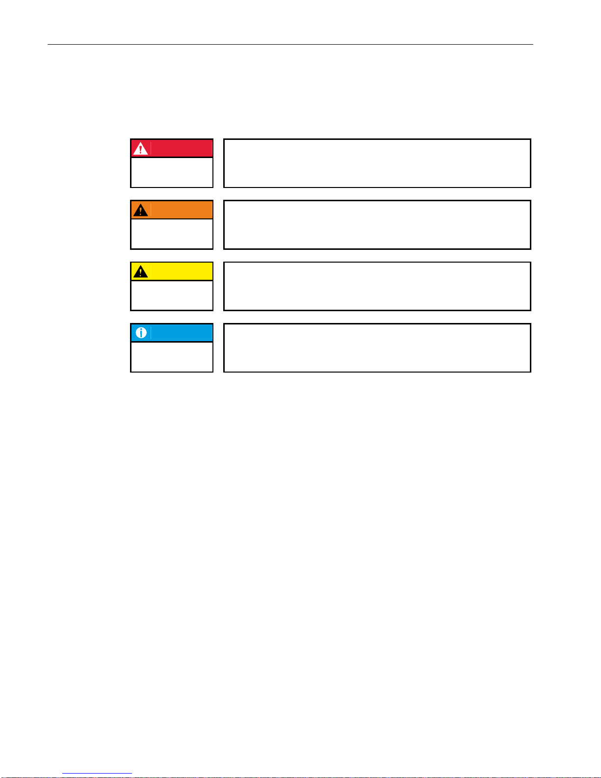
1.2. Hazard categories and terminology
DANGER
Immediate danger
Failure to observe the information indicated by this warning will result in death,
serious injury or extensive property damage.
WARNING
Potential danger
Failure to observe the information indicated by this warning may result in
death, serious injury or extensive property damage.
CAUTION
Danger
Failure to observe the information indicated by this warning may result in injury
or property damage.
NOTICE
No hazard
Information indicated in this manner provides additional notes concerning the
product.
Page 11

USER MANUAL 1.10 | DC1000 DIALOG-CONTROLLER
Berghof Automation GmbH | Harretstrasse 1 | 72800 Eningen | www.berghof.com
2VF100106FE05.docx | DC1000_HB_en_2D0982010ZD00.docx
11
1.3. Qualified personnel
Only qualified personnel may install, operate and maintain the Dialog Controller.
Within the context of this documentation and the safety information it contains, qualified personnel constitutes trained specialists who have the authority to mount, install, commission, ground and identify equipment, systems and power circuits in accordance with the standards of safety technology, and who are familiar
with the safety concepts of automation technology.
1.4. Due diligence
The operator or original equipment manufacturer (OEM) must ensure …
that the Dialog Controller is only employed for its intended use.
that the Dialog Controller is only employed in a fault-free, operational state.
that the equipment manual is always maintained in a complete and legible condition and is available at
the point-of-employment of the Dialog Controller.
that only properly qualified and authorized personnel mount, install, commission and maintain the
Dialog Controller.
that these specialists receive regular and ongoing instruction in all pertinent questions related to work
safety and environmental protection and that they are familiar with the contents of the equipment
manual, in particular, with the safety information it contains.
that the equipment identifiers as well as safety and warning information applied to the Dialog Control-
ler are not removed and that they are maintained in a legible condition.
that all international, federal, state and local ordinances governing the control of machinery and
equipment applicable at the location at which the Dialog Controller is employed are complied with.
that the users always have available all relevant information they require with regard to the Dialog
Controller and its employment.
Page 12
USER MANUAL 1.10 | DC1000 DIALOG-CONTROLLER
Berghof Automation GmbH | Harretstrasse 1 | 72800 Eningen | www.berghof.com
DC1000_HB_en_2D0982010ZD00.docx | 2VF100106FE05.docx
12
1.5. Basic safety measures
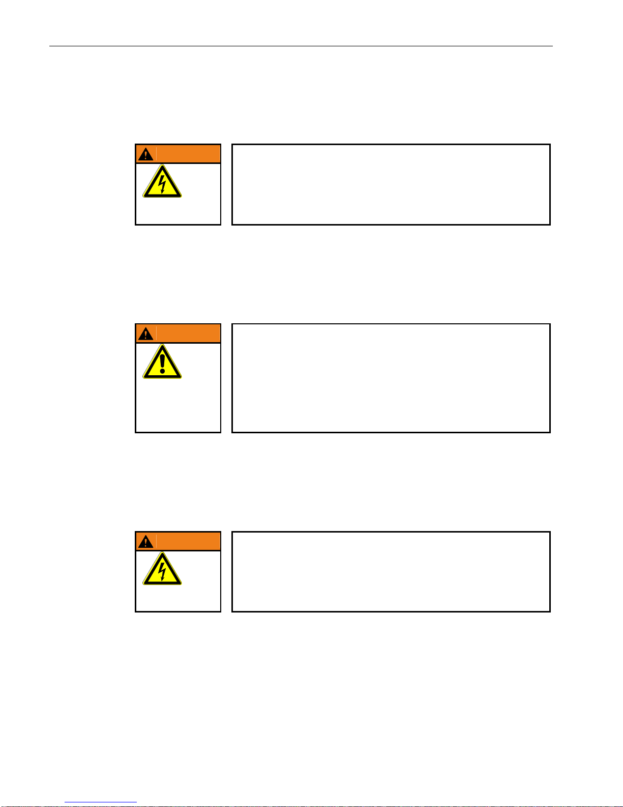
WARNING
If damage can be seen on the faceplate of the dialog controller, the device
must not be operated any more! It must be disconnected from the supply
voltage immediately!
Besides the danger of injury owing to the visibly sharp edges, there is also the
risk of touching parts under high voltage. Contact with high voltage can still
occur even some time after the supply voltage has been shut off.
HAZARDOUS
VOLTAGE
Working on the DC
Before beginning work on the Dialog Controller you must always
first ensure that the equipment is in a safe state,
then first switch the DC off, followed by the equipment, and
only then disconnect the DC from the equipment.
WARNING
Hazards due to unforeseeable functional and processing movements
when the Industrial PC is disconnected.
These can result in death, serious injury or extensive property damage.
All equipment components must be disconnected from the Dialog Controller
whenever the Dialog Controller is not being used for operational or control purposes, e.g., during maintenance or during functional checks after repairs.
Lock out and tag out all equipment components after they have been
switched off!
HAZARDOUS
PROCESSES
Opening the DC
First, please note all the tasks steps outlined in the above section “Working on the DC”. The supply voltage
must be switched off before opening the housing or when components are being installed or removed.
To do this, switch the power supply to the Dialog Controller off. Then remove the plug from the power supply
socket on the Dialog Controller.
WARNING
Do not open the housing cover with the power switched on!
Hazard due to contact with live components.
This can result in death, serious injury or extensive property damage.
Only open the housing cover once the Dialog Controller has been safely dis-
connected from the power supply.
HAZARDOUS
VOLTAGE
Page 13
USER MANUAL 1.10 | DC1000 DIALOG-CONTROLLER
Berghof Automation GmbH | Harretstrasse 1 | 72800 Eningen | www.berghof.com
2VF100106FE05.docx | DC1000_HB_en_2D0982010ZD00.docx
13
1.6. Use as prescribed
This is a modular automation system based on the CANbus, intended for industrial control applications
within the medium to high performance range.
The automation system is designed for use within Overvoltage Category I (IEC 364-4-443) for the controlling
and regulating of machinery and industrial processes in low-voltage installations in accordance with the following general parameters:
maximum rated supply voltage of 1,000 VAC (50/60 Hz) or 1,500 VDC;
for use in maximum category 2 pollution environment (EN 60950);
for use up to a maximum altitude of 2,000 m above msn;
for indoor use only in areas not exposed to direct UV radiation;
max. ambient temperature inside and outside the control cabinet is within the technical specifications
(see section “Technical data”)
Qualified project planning and design, proper transport, storage, installation, use and careful maintenance
are essential to the flawless and safe operation of the automation system.
The automation system may only be used within the scope of the data and applications specified in the
present documentation and associated user manuals.
The automation system is to be used only as follows:
as prescribed
in technically flawless condition
without arbitrary or unauthorized changes
exclusively by qualified users
The regulations of the German professional and trade associations, the German technical supervisory board
(TÜV), the VDE (Association of German electricians) or other corresponding national bodies are to be observed.
Safety-oriented (fail-safe) systems
Particular measures are required in connection with the use of SPC in safety-oriented systems. If an SPC is to
be used in a safety-oriented system, the user ought to seek the full advice of the SPC manufacturer in
addition to observing any standards or guidelines on safety installations which may be available.
WARNING
As with any electronic control system, the failure of particular components may result in uncontrolled and/or unpredictable operation.
All types of failure and the associated fuse systems are to be taken into account at system level. The advice of the SPC manufacturer should be sought if
necessary.
Page 14

USER MANUAL 1.10 | DC1000 DIALOG-CONTROLLER
Berghof Automation GmbH | Harretstrasse 1 | 72800 Eningen | www.berghof.com
DC1000_HB_en_2D0982010ZD00.docx | 2VF100106FE05.docx
14
1.7. Conformity declaration
Both the standard version of the Dialog Controller and with the extension modules mentioned below comply
with and make allowance for the following directives and standards:
EMC Directive 2014/30/EU
EN 61131-2:2007 Programmable logic controllers
Part 2: Equipment requirements and tests
Class B, connector cable of the I/O, max 30 m
EN 61000-6-2:2005/AC:2005 Electromagnetic compatibility (EMC)
Part 6-2: Generic standard – immunity for industrial environments
EN 61000-6-4:2007/A1:2011 Electromagnetic compatibility (EMC)
Part 6-4: Generic standard – electrostatic discharge for industrial environments
1.7.1. Extension modules
Conformity is declared to the above-stated directives for the extension modules given below, built into the
Dialog-Controller:
PROFIBUS-MASTER card
PROFIBUS-SLAVE card
PROFIBUS card (Master/Slave functionality)
I/O cards XR01 and XR02 with analog and digital I/O
No general conformity can be declared for extensions with contact line system, built into the DialogController:
I/O card with SC-CAN interface
With connected contact line system the compliance of the EMC requirements on the complete system must
be checked and ensured („fixed installation“ for the purpose of the EMC directive).
Page 15
USER MANUAL 1.10 | DC1000 DIALOG-CONTROLLER
Berghof Automation GmbH | Harretstrasse 1 | 72800 Eningen | www.berghof.com
2VF100106FE05.docx | DC1000_HB_en_2D0982010ZD00.docx
15
1.8. Transport and setup
NOTICE
Please note the specified storage conditions in the section “Technical
specifications”.
Transport
Protect the Dialog Controller against extreme mechanical stress during transport. Always transport the
Dialog Controller in its original packaging. The built-in components are extremely sensitive to jarring and
strong vibrations.
CAUTION
Condensation hazard resulting from climatic fluctuations
Risk of damage as a result of moisture forming on or in the Dialog Controller
(condensation). This can result in destruction of the device or consequential
damages.
After storage or transport in cold weather or under conditions of strongly fluctuating temperatures, the Dialog Controller must be allowed to slowly adjust to
the ambient temperature at its point of use before it can be taken into
service.
In case of condensation, the unit may not be taken into service for at least
12 hours (temperature compensation).
CONDENSATION
Unpacking
Proceed as follows:
Inspect the packaging for any external damage. If the packaging is severely damaged or if damage to
the contents can be detected, do not open the packaging any further. Immediately contact your shipper
and your supplier.
Remove the packaging. Do not discard the original packaging! The packaging can be used for sub-
sequent transport.
Inspect the contents for visible shipping damage.
Check the contents against the order for completeness. Save all included documentation. This docu-
mentation contains important information concerning the Dialog Controller and is an integral part of
the product.
If shipping damage is detected or if the received contents do not agree with the order, please contact
your supplier immediately.
Setup
This Dialog Controller is designed for installation in fully enclosed circuit cabinets of industrial machinery
and equipment. When installing the Dialog Controller, take particular care to ensure that the included seal
profiles are not damaged. Also ensure compliance with the ambient conditions specified under “Technical
specifications”.
Page 16

USER MANUAL 1.10 | DC1000 DIALOG-CONTROLLER
Berghof Automation GmbH | Harretstrasse 1 | 72800 Eningen | www.berghof.com
DC1000_HB_en_2D0982010ZD00.docx | 2VF100106FE05.docx
16
Blank page
Page 17

USER MANUAL 1.10 | DC1000 DIALOG-CONTROLLER
Berghof Automation GmbH | Harretstrasse 1 | 72800 Eningen | www.berghof.com
2VF100107FE10.docx | DC1000_HB_en_2D0982010ZD00.docx
17
2. Product description
The Dialog-Controller is a real-time control module with a display and a broad spectrum of data interfaces.
The module can be programmed in 'C' or in accordance with IEC 61131-3 (CODESYS 2.3).
Installation
The Dialog-Controllers are intended for front panel or switch cabinet installation in harsh industrial environments. Maintenance is minimal, thanks to their fan-free design and flash memory.
Processors
The Dialog-Controller is equipped with either a 266 MHz or 400 MHz POWERPCTM processor from Freescale.
Display
The great differences in the appearance of the Dialog-Controller are based on the selection of the employed
display technology and a common display diagonal size. 5.7” units with a monochrome (STN), color (CSTN)
or TFT display are available. Above a diagonal screen size of 10.4” only TFT displays are employed. Unit
housing dimensions and protective method (IP65 on the front) do not depend on whether the version in
question has a touch screen or matrix keypad.
Ethernet
A 10/100 MBit/s Ethernet interface is included. TCP/IP and UDP/IP protocols offer highly flexible connections to visualization software, higher order control units or an IT infrastructure.
USB ports
The two USB host ports provide interfaces for widely dispersed peripheral devices. For example, one USB
stick can be used to quickly and easily perform application updates or data extraction. Please contact our
Technical Support if no driver support is available for a specific USB device.
CAN ports
The Dialog-Controller is equipped with two standard CAN interfaces, both of which can be operated at
1 MBit/s.
Serial ports
A total of three serial ports can be used on the Dialog-Controller. The RS232 programming interface is supplemented by an additional RS232 and an RS485 port.
E-bus extension
The Dialog-Controller’s I/O level can be expanded via the E-bus socket to include up to seven E-bus subscribers.
Short description
Page 18
USER MANUAL 1.10 | DC1000 DIALOG-CONTROLLER
Berghof Automation GmbH | Harretstrasse 1 | 72800 Eningen | www.berghof.com
DC1000_HB_en_2D0982010ZD00.docx | 2VF100107FE10.docx
18
Expansion slots
The device is equipped with three expansion slots for expansion cards (e.g., I/O cards) with the associated
SPI interface. Alternately, one of the slots can be used for an “Anybus®” embedded bus module (e.g., Profibus
DP) manufactured by HMS.
Real-time clock
A software interface can be used to set or reset a real-time clock equipped with a backup battery.
SD card reader
Data can be written to or read from memory cards using the conventional MMC/SD card interfaces.
NOTICE
If the SD card reader is activated, then the second RS232 interface (X5) is not
longer available.
Performance feature overview
Freescale POWERPCTM CPU 266 (400) MHz
Application program and data memory (RAM): 64 (128) MB onboard / 32 (96) MB for the application
Application program memory (Flash): 16 (32) MB onboard / 8 (24) MB for the application
Retain memory 16 KB
1 Ethernet 10/100 port
1 (3) USB host ports
1 (2) CAN ports
1 RS232 serial port for programming tools and applications
1 (2) serial data ports RS232 / RS485
I/O level locally expandable via an internal E-bus for up to seven subscribers (digital / analog)
Up to 3 onboard expansion slots for I/Os and a bus module
Real-time clock
MMC/SD card slot
The scope of supply of the controller module consists of:
Dialog-Controller DC10xx
incl. 2-pin plug-in connector for power supply
Scope of supply
Page 19
USER MANUAL 1.10 | DC1000 DIALOG-CONTROLLER
Berghof Automation GmbH | Harretstrasse 1 | 72800 Eningen | www.berghof.com
2VF100107FE10.docx | DC1000_HB_en_2D0982010ZD00.docx
19
2.1. Identification
Product: Dialog-Controller, Type DC10xx
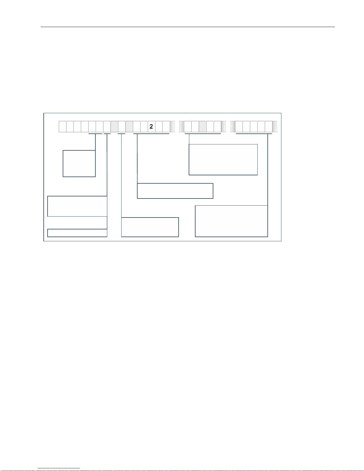
Identification code
The features of the Dialog-Controller (see nameplate) can be itemised according to the identification code.
2VF100227DG04.cdr
D C 1 0 05M T M P 66
1 2 3 4 5 6 7 8 9 10 11 12 13 14 15 ... ...
S C AP B A CIS
Screen size
(diagonal)
Activation method
Processor type
Display technology
Resolution
Extension-Modules
05
10
12
15
=
= 10,4”
= 12,1”
= 5,0”1
5,7”
M =
= Color (CSTN)
= Color TFT
C
T
Monochrome (STN)
V = VGA 640 x 480
T
K
A
= Touchpanel
= Keyboard
= Touch + Keyboard
BASIC
CLEAN
= DC1000 with
basic equipment
= Continuous of the
front foil sheeting
= compact modelCP
MP266
MP400
= Power PC 266 MHz
= Power PC 400 MHz
SC PS= I/O card
= Profibus Slave
= Profibus Master
= Profibus Master/Slave
= XR I/O card
PM
PA
IO
Model
Page 20
USER MANUAL 1.10 | DC1000 DIALOG-CONTROLLER
Berghof Automation GmbH | Harretstrasse 1 | 72800 Eningen | www.berghof.com
DC1000_HB_en_2D0982010ZD00.docx | 2VF100107FE10.docx
20
2.2. The different versions of the Dialog-Controller
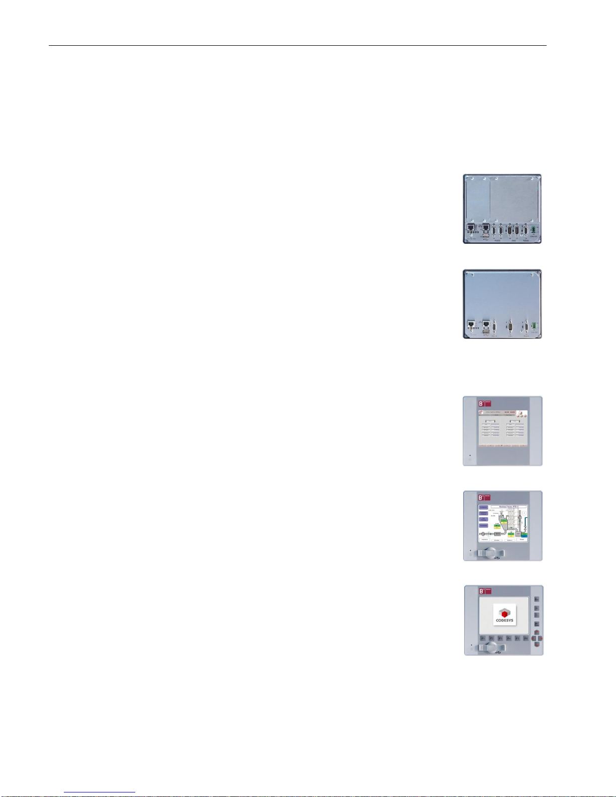
2.2.1. Interfaces
Communication is the forte of the DC1000. Its spectrum of interfaces and extension options makes is the reason for this. The DC1000 with a Prime interface is
extremely adaptable.
The maximum scope of the interfaces can be supplemented with further communication an I/O extension cards. So it is easy to always find the rigth automation
solution.
2VF100397DG00.cdr
The DC1000 with the Basic Interface is optimal for standard applications.
With high processor power and equipped minimally with interfaces, it is the right
solution for a price sensitive market.
2VF100398DG00.cdr
2.2.2. Front foil sheeting
If cleanliness is a priority, the Clean Front is the right choice. Dust and dirt do not
stand a chance here; and what's more, it is easy to clean.
2VF100399DG01.cdr
Machine parameters or data records can be exchanged simply and fast by means
of a USB stick. It is very convenient to have a USB port available at the front.
The Connect front is distinguished by the USB port at the front with IP65 cover.
2VF100400DG01.cdr
Touch screen or membrane key pad: this is not merely a philosophical operational
issue. Gloves are often needed on site. If this is the case, keys are simple and safe
to use.
2VF100401DG01.cdr
Prime Interface
Basic Interface
Clean Touch
Connect Touch
Connect Key
Page 21
USER MANUAL 1.10 | DC1000 DIALOG-CONTROLLER
Berghof Automation GmbH | Harretstrasse 1 | 72800 Eningen | www.berghof.com
2VF100107FE10.docx | DC1000_HB_en_2D0982010ZD00.docx
21
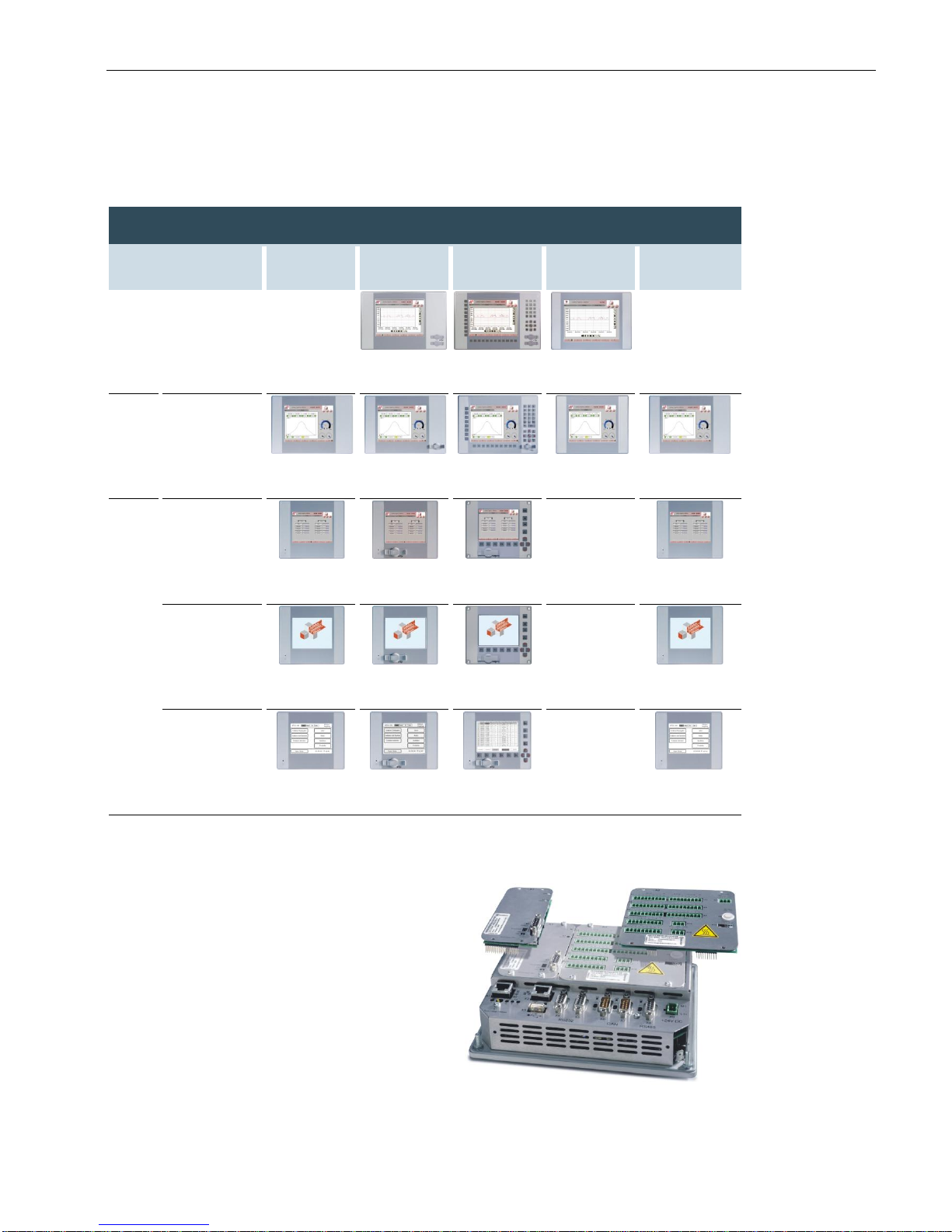
2.2.3. Overview of types
Prime Interface
Basic
Interface
Clean
Touch
Connect
Touch
Connect
Key
Compact
Touch
Clean
Touch
12,1“
SVGA
800 x 600
65536 colours
(16 bit p. P.)
DC1012T T
DC1012T K
DC1012T T
Clean
10,4“
VGA
640 x 480
65536 colours
(16 bit p. P.)
DC1010T T
Clean
DC1010T T
DC1010T K
DC1010T T
Clean
DC1010T T
Basic
5,7“
VGA
640 x 480
65536 colours
(16 bit p. P.)
DC1005V T
Clean
DC 1005V T
DC1005V K
DC1005V T
Basic
QVGA
320 x 240
256 colours
(8 bit p. P.)
DC1005T T
Clean
DC1005T T
DC1005T K
DC1005T T
Basic
QVGA
320 x 240
monochrome
4 shades of
grey
DC1005M T
Clean
DC1005M T
DC1005M K
DC1005M T
Basic
2.2.4. Variable thanks to extension cards
The DC1000 can be fitted with a maximum of three
extension cards.
The spectrum encompasses pure I/O cards as well as
communication cards, which are already installed by
Berghof.
The range is constantly being extended conforming to
the market requirements.
Extension cards can only be fitted in Dialog-Controllers with Prime Interface.
2VF100403DG00.cdr
Page 22
USER MANUAL 1.10 | DC1000 DIALOG-CONTROLLER
Berghof Automation GmbH | Harretstrasse 1 | 72800 Eningen | www.berghof.com
DC1000_HB_en_2D0982010ZD00.docx | 2VF100107FE10.docx
22
2.3. Dialog-Controller DC1005 / DC1010 / DC1012
construction
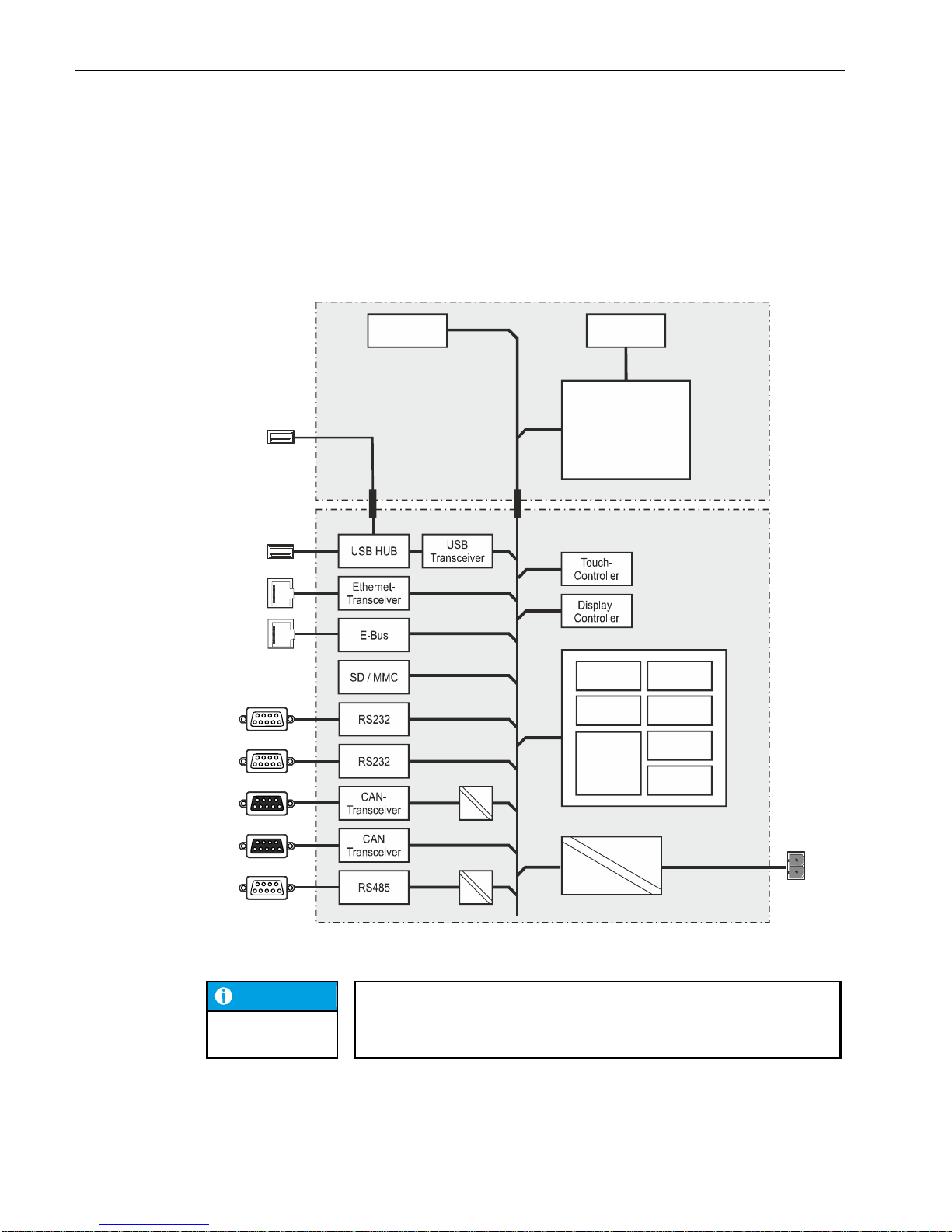
2.3.1. Block circuit diagram
2VF100233DG01.cdr
NOTICE
No potential isolation of the CAN and RS485 interface on the Basic Interface
version.
FRONT
Front
USB
Inverter
Display
Touch /
Keyboard
Display
Unit
X2
X1
X8
X6
X4
X5
X7
X3
+24 V
CPU
Grafik CAN
SIO
Flash
RAM
USB
X9
BASIS
Controller
Page 23
USER MANUAL 1.10 | DC1000 DIALOG-CONTROLLER
Berghof Automation GmbH | Harretstrasse 1 | 72800 Eningen | www.berghof.com
2VF100107FE10.docx | DC1000_HB_en_2D0982010ZD00.docx
23
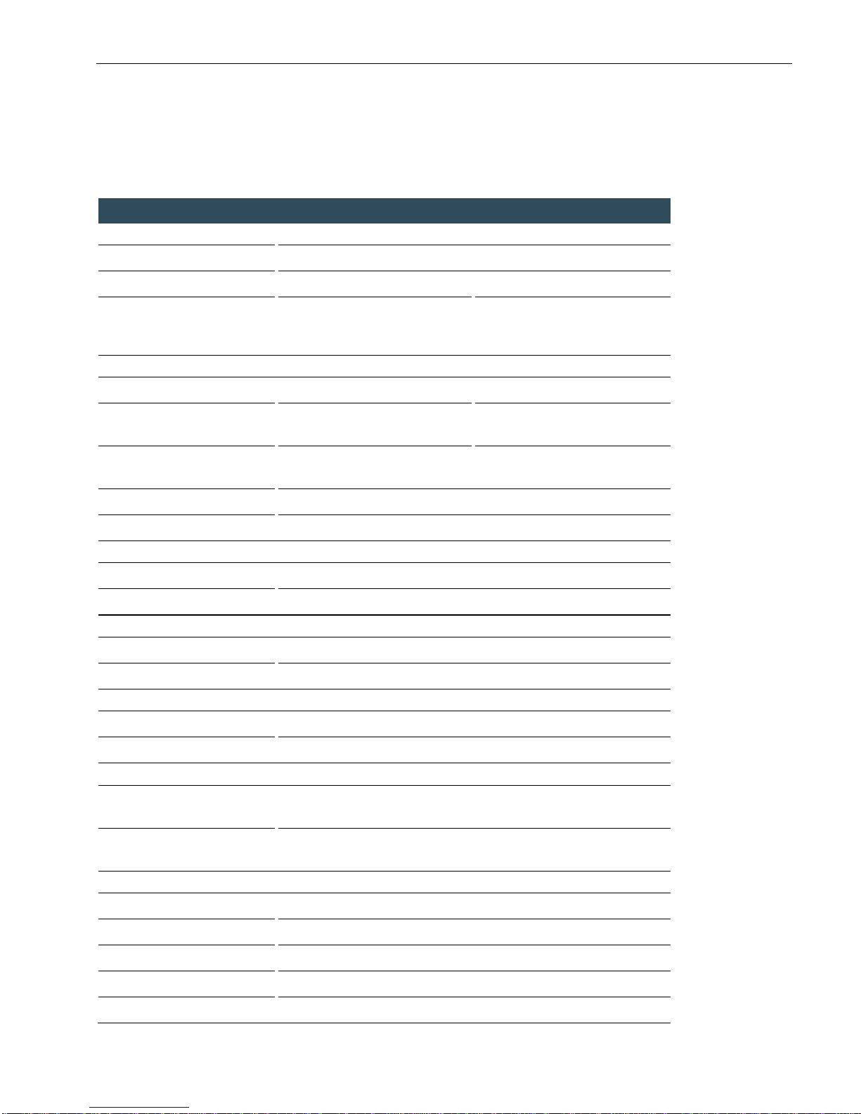
2.4. Technical data DC1005
Module data
Display
1/4 VGA
VGA
Diagonal measurement
5.7“
Resolution
320 x 240 pixels
640 x 480 pixels
Colors
Monochrome (STN): 4
Color (CSTN): 256 (8 bits / pixel)
Color TFT: 256 (8 bits / pixel)
Color TFT: 65536 (16 bits / pixel)
CPU, application memory
CPU
Freescale PowerPC 266 MHz
400 MHz
Program memory (Flash)
16 MB onboard /
8 MB for application
32 MB onboard /
24 MB for application
Program memory and data
memory (RAM)
64 MB onboard /
32 MB for application
128 MB onboard /
96 MB for application
Retain memory
16 kB
Development environment
CP1131 (CODESYS 2.3)
Dimensions and weights
Dimensions (WxHxD [mm])
194x172x52 (+6 mm front panel)
Weight
Approx. 1.5 kg
Operating conditions
Ambient temperature range
0 °C to +55 °C (if installation rule is adhered to)
Relative humidity
Max. 85 %, non-condensing (monochrome: max. 75 %)
Transport, storage
Ambient temperature range
-20 °C to +70 °C
Relative humidity
Max. 85 %, non-condensing (monochrome: max. 75 %)
Shock resistance
Vibration
Sinusoidal (EN 60068-2-6) test: Fc
10 … 150 Hz, 1 G (operation mode)
Shock resistance
15 G (approx. 150 m/s2); duration:10 ms;
semi-sinusoidal (EN 60068-2-27) test: Ea
EMC, protection type
Interference emission
EN 61000-6-4, industrial environments
Interference resistance
EN 61000-6-2, industrial environments
Protection class
III
Insulating resistance
EN 61131-2; DC 500 V test voltage
Protection type
IP20 (front: IP65)
Page 24

USER MANUAL 1.10 | DC1000 DIALOG-CONTROLLER
Berghof Automation GmbH | Harretstrasse 1 | 72800 Eningen | www.berghof.com
DC1000_HB_en_2D0982010ZD00.docx | 2VF100107FE10.docx
24
Module data
Power supply (24 V power pack)
Supply voltage
+24 VDC (-15 % / +20 %) SELV,
max. alternating component: 5 %,
max. voltage interruption 1 ms (10 ms only with power supply after
61131-2)
Current consumption
Typically 1.0 A; max. 2.0 A at +24 VDC;
Fusing depending on the I/O load, max. 12 A
Polarity reversal protection
Yes
Potential isolation
Yes, between CAN bus and I/Os.
Ethernet port
Number / interface type
1 x 10/100 Base-T
Connection method
RJ45
USB ports
Number / interface types
1 x host USB, Rev. 1.1 (on rear)
1 x host USB, Rev. 1.1 (on front, on Prime Interface version)
Plug/unplug cycles
Max. 1,000
CAN bus ports
Number / interface types
2 x Standard CAN ISO 11898
1 x Standard CAN ISO 11898 on Basic Interface
Potential isolation
CAN0 (X6) potential isolated (Prime Interface only)
Transmission rate
Max. 1 Mbit/s
Terminating resistor
Switchable
Serial ports
Number / interface types
2 x RS232 (1x RS232 on Basic Interface)
1 x RS485
Potential isolation
RS485 (X8) potential isolated (Prime Interface only)
Terminating resistor
Switchable with the RS485
E-bus port
Interface type
I/O expansion bus for up to 7 E-bus subscribers
Expansion slots
Number / interface types
3 slots for 3 I/O modules or 2 I/O modules and one AnyBus® module
(Prime Interface only)
Further features
Real-time clock
Yes, battery backed.
SD card
1 SD card slot or RS232 (X5) (Prime Interface only)
Page 25
USER MANUAL 1.10 | DC1000 DIALOG-CONTROLLER
Berghof Automation GmbH | Harretstrasse 1 | 72800 Eningen | www.berghof.com
2VF100107FE10.docx | DC1000_HB_en_2D0982010ZD00.docx
25
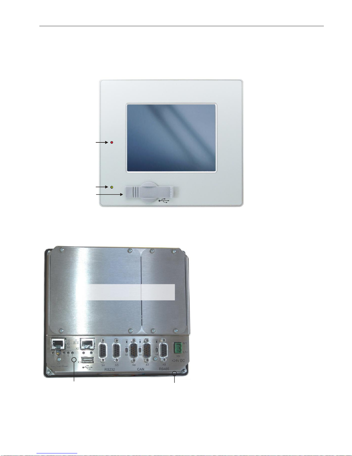
2.4.1. DC1005 Front view
2VF100229DG01.cdr
2.4.2. DC1005 Rear view
2VF100230DG01.cdr
Front-USB
Power Status-LED
LED (red) optional
controlled by application
Cover interface boards
Connections Frontpanel
Page 26
USER MANUAL 1.10 | DC1000 DIALOG-CONTROLLER
Berghof Automation GmbH | Harretstrasse 1 | 72800 Eningen | www.berghof.com
DC1000_HB_en_2D0982010ZD00.docx | 2VF100107FE10.docx
26
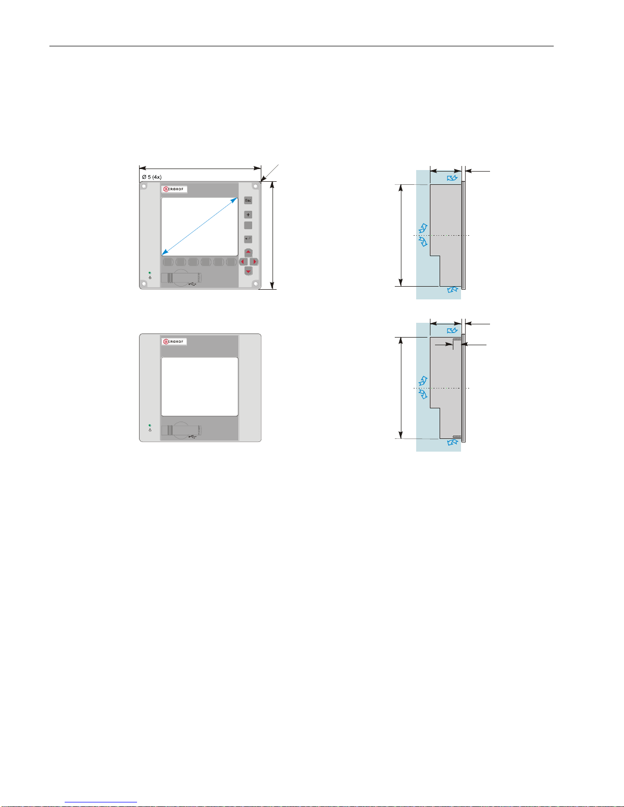
2.4.3. DC1005 Dimensions
Dimensions are identical for units equipped with either a keyboard or a touchpad.
2VF100234DG03.cdr
max. 52
ca. 158
6
14
Freie Luftzirkulation
free air circulation
Freiraum / clearance > 20 mm
max. 52
ca. 158
6
Freie Luftzirkulation
free air circulation
Freiraum / clearance > 20 mm
Alle Maße in [mm]
All dimensions in [mm]
194
172
DC1005M K
R
6
F2 F3 F4
F5 F6
F1
Enter
_
5
,
7
”
DC1005C T
DC1005T T
Schraubenmontage
Screwing assembly
Bolzenmontage
Bolt assembly
G
e
w
i
n
d
e
b
o
l
z
e
n
M
4
x
1
4
m
m
t
h
r
e
a
d
e
d
b
o
l
t
Page 27
USER MANUAL 1.10 | DC1000 DIALOG-CONTROLLER
Berghof Automation GmbH | Harretstrasse 1 | 72800 Eningen | www.berghof.com
2VF100107FE10.docx | DC1000_HB_en_2D0982010ZD00.docx
27
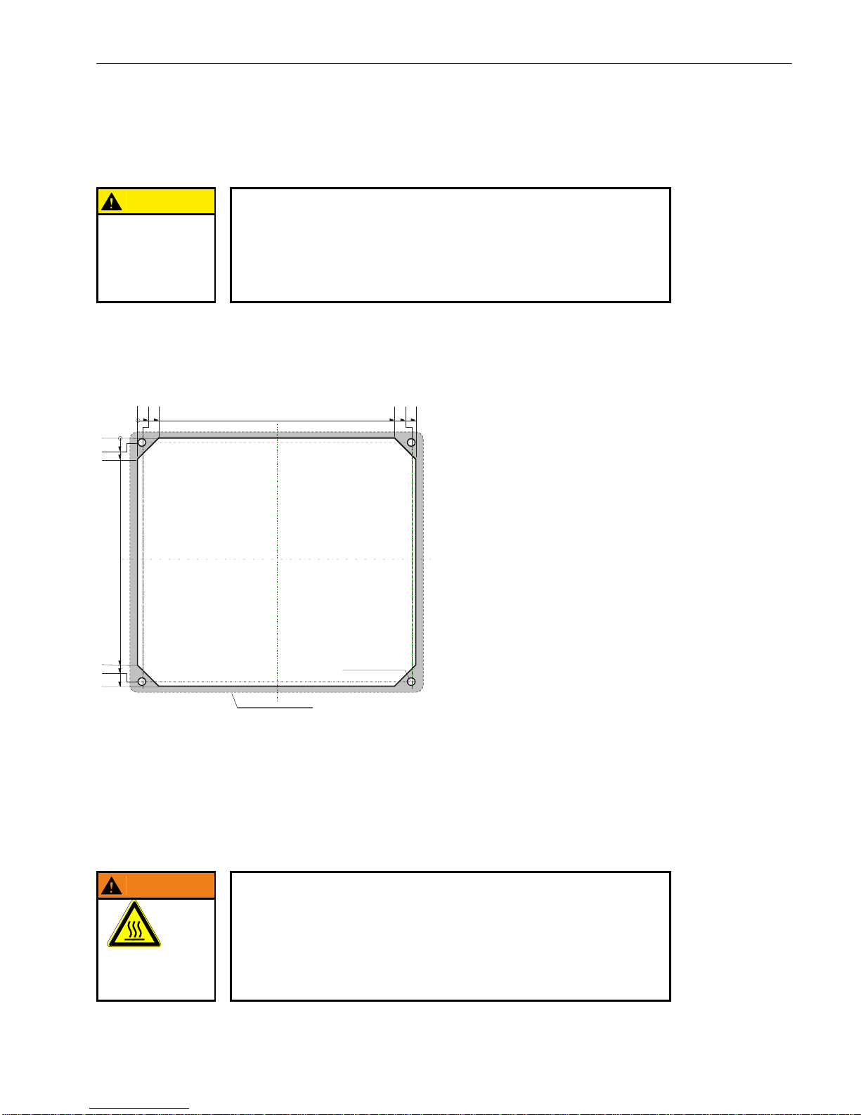
2.4.4. DC1005 Panel cutout
CAUTION
Installation instruction:
Only install the Dialog-Controller on a level surface!
The support points on the Dialog-Controller may not deviate from one another
by more than +/-0.5 mm. If the Dialog-Controller is nonetheless mounted on a
base which is not level, mechanical tension can result in cracks in the front
panel.
The Dialog-Controller is intended for front installation. A square panel cutout is required. The support material thickness may not exceed 6 mm. The panel cutouts are identical for units equipped with either a keyboard or a touchpad.
2VF100235DG00.cdr
2.4.5. Mounting regulation DC1005
The Dialog-Controllers are designed for automatic convection cooling.
The Dialog-Controllers must be mounted vertically onto a metallic mounting plate.
WARNING
Danger of overheating and fire!
The Dialog-Controller may be destroyed even at a permissible ambient temperature if the convection cooling cannot function because it is built-in.
It must therefore be installed vertically and the upper and lower housing apertures must not be covered over!
DANGER OF
OVERHEATING
AND FIRE!
Vertical
installation
Frontansicht
Front view
Fronttafel-Ausschnitt
184 x 162
front panel cut out
Frontrahmen / front frame
194 x 172
0
3
3
14
14
148
159
162
170
181
184
0
Bohrungen /
5 mm (4x)
drills
Ø
Alle Maße in [mm]
All dimensions in [mm]
Page 28
USER MANUAL 1.10 | DC1000 DIALOG-CONTROLLER
Berghof Automation GmbH | Harretstrasse 1 | 72800 Eningen | www.berghof.com
DC1000_HB_en_2D0982010ZD00.docx | 2VF100107FE10.docx
28
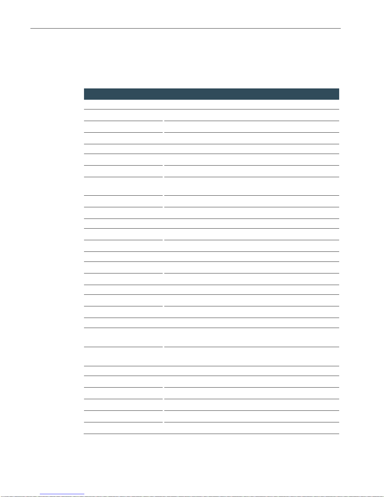
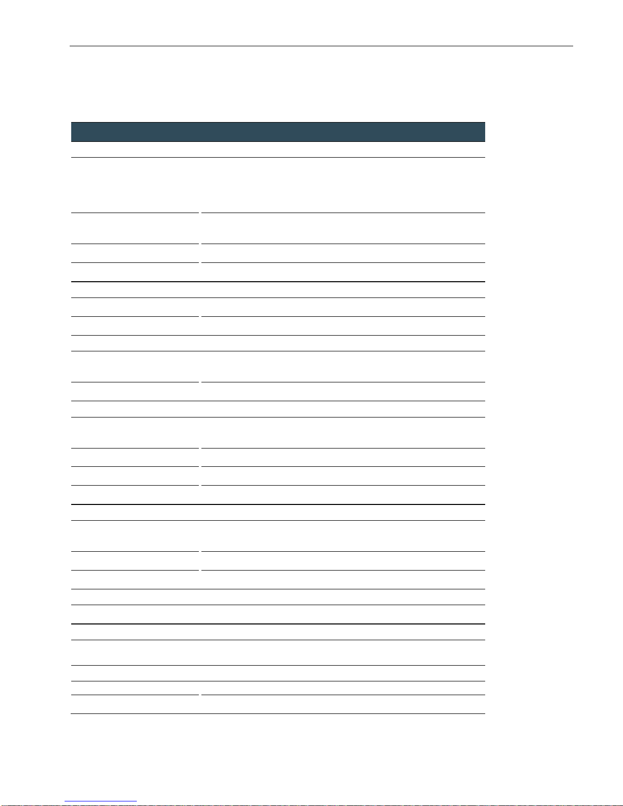
2.5. Technical data DC1010
Module data
Display
Diagonal measurement
10.4“
Resolution
640 x 480 pixels (VGA)
Colors
65536 (16 bit per pixel)
CPU, application memory
CPU
Freescale PowerPC 400 MHz
Program memory (Flash)
32 MB onboard / 24 MB for application
Program memory and data
memory (RAM)
128 MB onboard / 96 MB for application
Retain memory
16 kB
Development environment
CP1131 (CODESYS 2.3)
Dimensions and weights
Dimensions (WxHxD [mm])
360x260x77 (+6 mm front panel)
Weight
Approx. 5 kg
Operating conditions
Ambient temperature range
0 °C to +55 °C (if installation rule is adhered to)
Relative humidity
Max. 90 %, non-condensing
Transport, storage
Ambient temperature range
-20 °C to +70 °C
Relative humidity
Max. 90 %, non-condensing
Shock resistance
Vibration
Sinusoidal (EN 60068-2-6) test: Fc
10 … 150 Hz, 1 G (operation mode)
Shock resistance
15 G (approx. 150 m/s2); duration:10 ms;
semi-sinusoidal (EN 60068-2-27) test: Ea
EMC, protection type
Interference emission
EN 61000-6-4, industrial environments
Interference resistance
EN 61000-6-2, industrial environments
Protection class
III
Insulating resistance
EN 61131-2; DC 500 V test voltage
Protection type
IP20 (front: IP65)
Page 29
USER MANUAL 1.10 | DC1000 DIALOG-CONTROLLER
Berghof Automation GmbH | Harretstrasse 1 | 72800 Eningen | www.berghof.com
2VF100107FE10.docx | DC1000_HB_en_2D0982010ZD00.docx
29
Module data
Power supply (24 V power pack)
Supply voltage
+24 VDC (-15 % / +20 %) SELV,
max. alternating component: 5 %,
max. voltage interruption 1 ms (10 ms only with power supply after
61131-2)
Current consumption
Typically 1.0 A; max. 2.0 A at +24 VDC;
Fusing depending on the I/O load, max. 12 A
Polarity reversal protection
Yes
Potential isolation
Yes, between CAN bus and I/Os.
Ethernet port
Number / interface type
1 x 10/100 Base-T
Connection method
RJ45
USB ports
Number / interface types
1 x host USB, Rev. 1.1 (on rear)
1 x host USB, Rev. 1.1 (on front, Prime Interface only)
Plug/unplug cycles
Max. 1,000
CAN bus ports
Number / interface types
2 x Standard CAN ISO 11898 Prime Interface
1 x Standard CAN ISO 11898 Basic Interface
Potential isolation
CAN0 (X6) potential isolated (Prime Interface only)
Transmission rate
Max. 1 Mbit/s
Terminating resistor
Switchable
Serial ports
Number / interface types
2 x RS232 Prime Interface / 1 x RS232 Basic Interface
1 x RS485
Potential isolation
RS485 (X8) potential isolated (Prime Interface only)
Terminating resistor
Switchable with the RS485
E-bus port
Interface type
I/O expansion bus for up to 7 E-bus subscribers
Expansion slots
Number / interface types
3 slots for 3 I/O modules or 2 I/O modules and one AnyBus® module
(Prime Interface only)
Further features
Real-time clock
Yes, battery backed.
SD card
1 SD card slot or RS232 (X5) (Prime Interface only)
Page 30
USER MANUAL 1.10 | DC1000 DIALOG-CONTROLLER
Berghof Automation GmbH | Harretstrasse 1 | 72800 Eningen | www.berghof.com
DC1000_HB_en_2D0982010ZD00.docx | 2VF100107FE10.docx
30
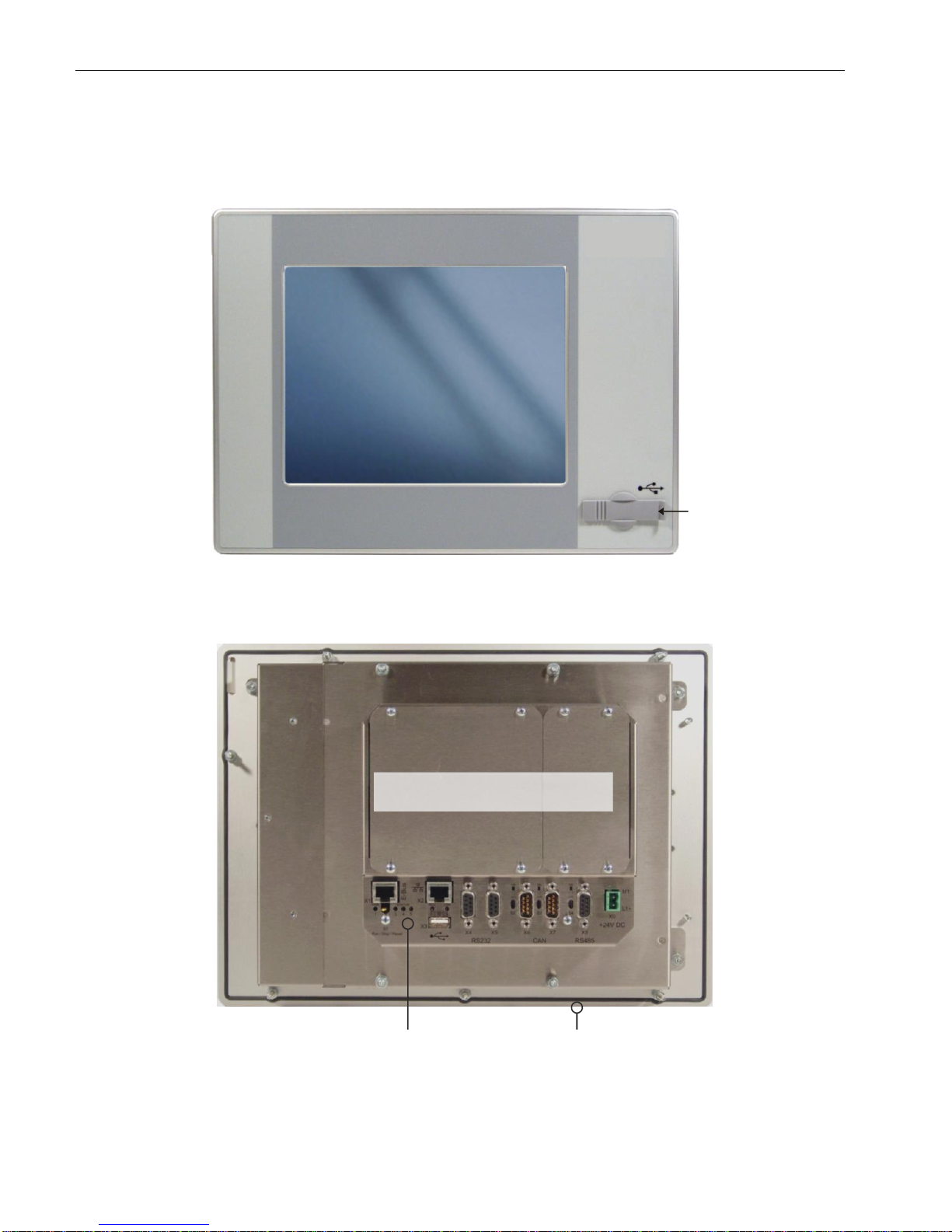
2.5.1. DC1010 Front view
2VF100241DG01.cdr
2.5.2. DC1010 Rear view
2VF100242DG01.cdr
Front-USB
Cover interface boards
Connections
Frontpanel
Page 31
USER MANUAL 1.10 | DC1000 DIALOG-CONTROLLER
Berghof Automation GmbH | Harretstrasse 1 | 72800 Eningen | www.berghof.com
2VF100107FE10.docx | DC1000_HB_en_2D0982010ZD00.docx
31
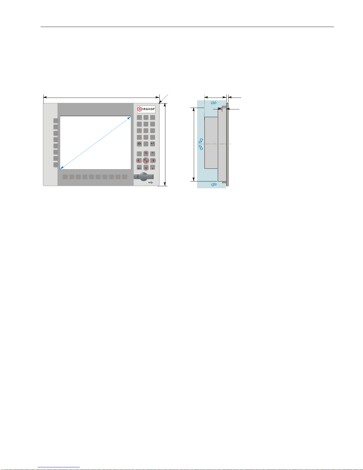
2.5.3. DC1010 Dimensions
Dimensions are identical for units equipped with either a keyboard or a touchpad.
2VF100243DG01.cdr
Alle Maße in [mm] / All dimensions in [mm]
360
260
max. 77
ca. 228
6
Freie Luftzirkulation
free air circulation
Freiraum / clearance > 20 mm
BkSp
PgUp
Pos1
PgDn
7
0
.
1
2
3
Ctrl
6
98
54
Enter
Shift
_
S2
S3
S4
S5
S6
S7
S8
S1
F2 F3 F4 F5 F6 F7
F8 F9 F10
F1
1
0
,
4
"
DC1010T K
R
8
16
G
e
w
i
n
d
e
b
o
l
z
e
n
M
4
x
1
6
m
m
t
h
r
e
a
d
e
d
b
o
l
t
Page 32
USER MANUAL 1.10 | DC1000 DIALOG-CONTROLLER
Berghof Automation GmbH | Harretstrasse 1 | 72800 Eningen | www.berghof.com
DC1000_HB_en_2D0982010ZD00.docx | 2VF100107FE10.docx
32
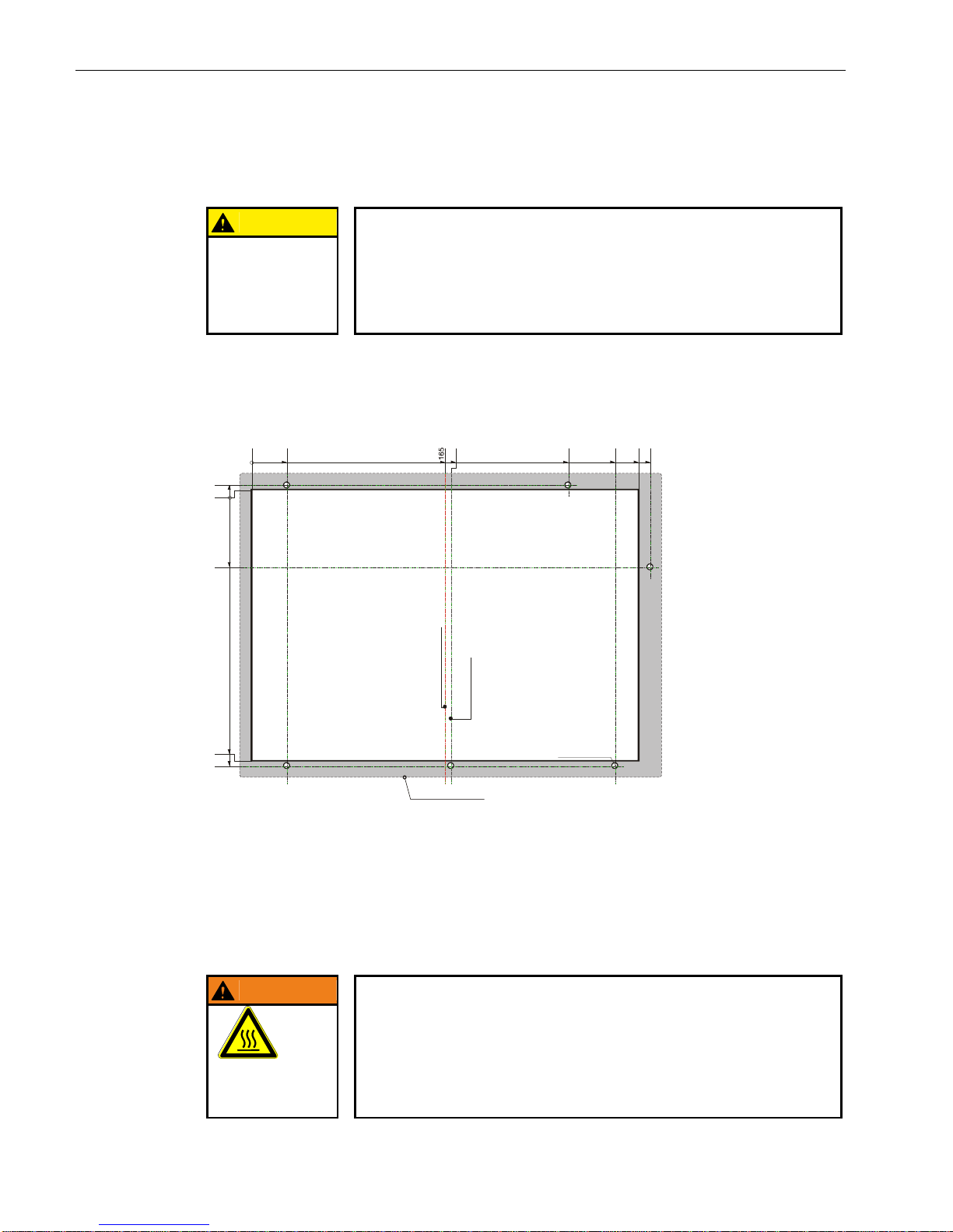
2.5.4. DC1010 Panel cutout
CAUTION
Installation instruction:
Only install the Dialog-Controller on a level surface!
The support points on the Dialog-Controller may not deviate from one another
by more than +/-0.5 mm. If the Dialog-Controller is nonetheless mounted on a
base which is not level, mechanical tension can result in cracks in the front
panel!
The Dialog-Controller is intended for front installation. A square panel cutout is required. The support material thickness may not exceed 6 mm. The panel cutouts are identical for units equipped with either a keyboard or a touch panel.
2VF100244DG00.cdr
2.5.5. Mounting regulation DC1010
The Dialog-Controllers are designed for automatic convection cooling.
The Dialog-Controllers must be mounted vertically onto a metallic mounting plate.
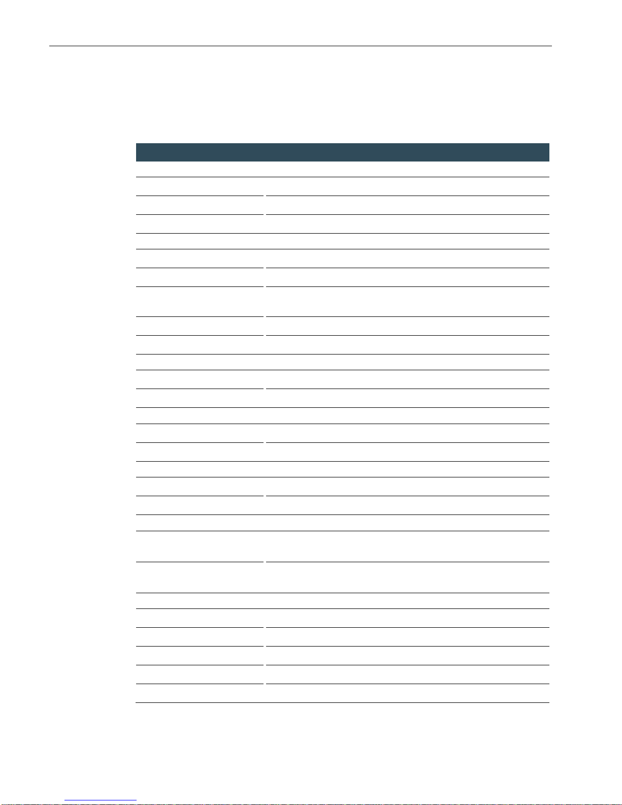
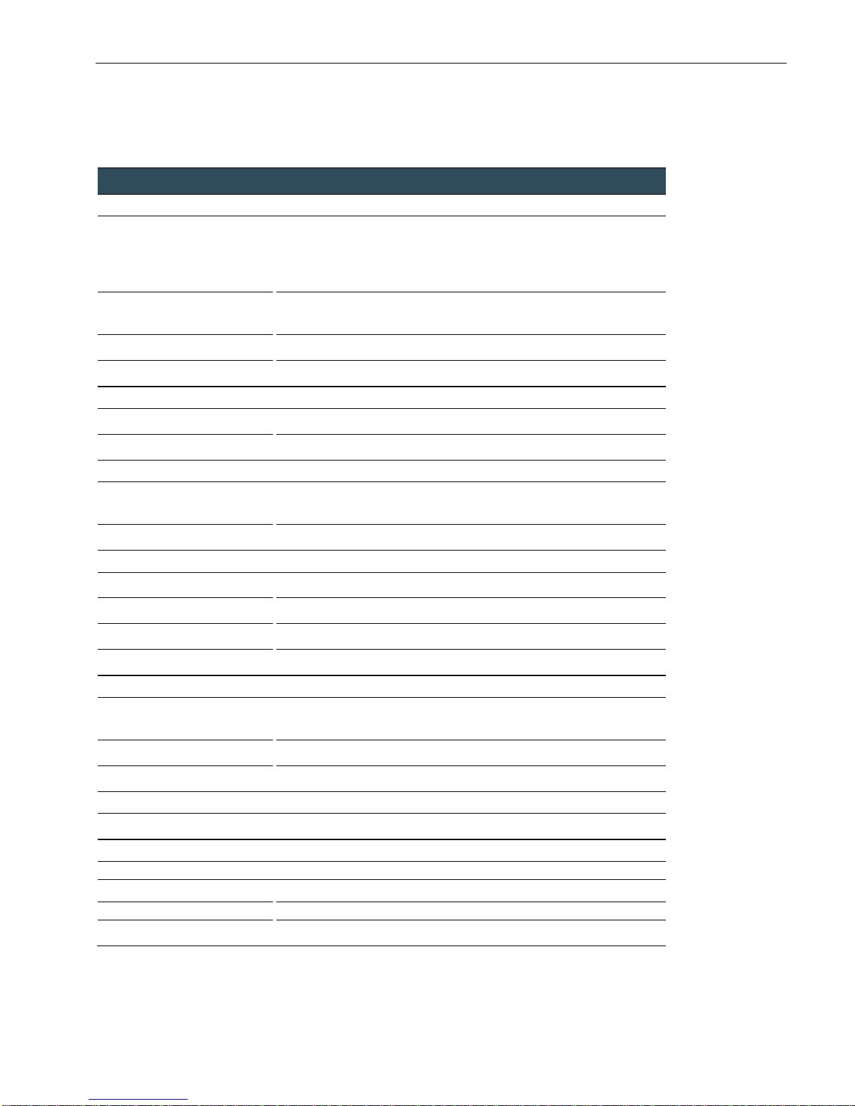
WARNING
Danger of overheating and fire!
The Dialog-Controller may be destroyed even at a permissible ambient temperature if the convection cooling cannot function because it is built-in.
It must therefore be installed vertically and the upper and lower housing apertures must not be covered over!
DANGER OF
OVERHEATING
AND FIRE!
Vertical
installation
0
30
270
330
340
Bohrungen /
5 mm (6x)
drills
Ø
0
4
-66
-232
-236
170
310
Mittelachse Frontplatte
centerline of front panel
Mittelachse Ausschnitt
centerline of front panel cut out
Alle Maße in [mm] / All dimensions in [mm]
Frontansicht
Front view
Fronttafel-Ausschnitt
330 x 232
front panel cut out
Frontrahmen / front frame
360 x 260
Page 33
USER MANUAL 1.10 | DC1000 DIALOG-CONTROLLER
Berghof Automation GmbH | Harretstrasse 1 | 72800 Eningen | www.berghof.com
2VF100107FE10.docx | DC1000_HB_en_2D0982010ZD00.docx
33
2.6. Technical data DC1010 Compact (CP)
Module data
Display
Diagonal measurement
10.4“
Resolution
640 x 480 pixels (VGA)
Colors
65536 (16 bit per pixel)
CPU, application memory
CPU
Freescale PowerPC 400 MHz
Program memory (Flash)
32 MB onboard / 24 MB for application
Program memory and data
memory (RAM)
128 MB onboard / 96 MB for application
Retain memory
16 kB
Development environment
CP1131 (CODESYS 2.3)
Dimensions and weights
Dimensions (WxHxD [mm])
313x250x77 (+6 mm front panel)
Weight
Approx. 5 kg
Operating conditions
Ambient temperature range
0 °C to +55 °C (if installation rule is adhered to)
Relative humidity
Max. 90 %, non-condensing
Transport, storage
Ambient temperature range
-20 °C to +70 °C
Relative humidity
Max. 90 %, non-condensing
Shock resistance
Vibration
Sinusoidal (EN 60068-2-6) test: Fc
10 … 150 Hz, 1 G (operation mode)
Shock resistance
15 G (approx. 150 m/s2); duration:10 ms;
semi-sinusoidal (EN 60068-2-27) test: Ea
EMC, protection type
Interference emission
EN 61000-6-4, industrial environments
Interference resistance
EN 61000-6-2, industrial environments
Protection class
III
Insulating resistance
EN 61131-2; DC 500 V test voltage
Protection type
IP20 (front: IP65)
Page 34

USER MANUAL 1.10 | DC1000 DIALOG-CONTROLLER
Berghof Automation GmbH | Harretstrasse 1 | 72800 Eningen | www.berghof.com
DC1000_HB_en_2D0982010ZD00.docx | 2VF100107FE10.docx
34
Module data
Power supply (24 V power pack)
Supply voltage
+24 VDC (-15 % / +20 %) SELV,
max. alternating component: 5 %,
max. voltage interruption 1 ms (10 ms only with power supply after
61131-2)
Current consumption
Typically 1.0 A; max. 2.0 A at +24 VDC;
Fusing depending on the I/O load, max. 12 A
Polarity reversal protection
Yes
Potential isolation
Yes, between CAN bus and I/Os.
Ethernet port
Number / interface type
1 x 10/100 Base-T
Connection method
RJ45
USB ports
Number / interface types
1 x host USB, Rev. 1.1 (on rear)
1 x host USB, Rev. 1.1 (on front, Prime Interface only)
Plug/unplug cycles
Max. 1,000
CAN bus ports
Number / interface types
2 x Standard CAN ISO 11898 Prime Interface
1 x Standard CAN ISO 11898 Basic Interface
Potential isolation
CAN0 (X6) potential isolated (Prime Interface only)
Transmission rate
Max. 1 Mbit/s
Terminating resistor
Switchable
Serial ports
Number / interface types
2 x RS232 Prime Interface / 1 x RS232 Basic Interface
1 x RS485
Potential isolation
RS485 (X8) potential isolated (Prime Interface only)
Terminating resistor
Switchable with the RS485
E-bus port
Interface type
I/O expansion bus for up to 7 E-bus subscribers
Expansion slots
Number / interface types
3 slots for 3 I/O modules or 2 I/O modules and one AnyBus® module
(Prime Interface only)
Further features
Real-time clock
Yes, battery backed.
SD card
1 SD card slot or RS232 (X5) (Prime Interface only)
Page 35
USER MANUAL 1.10 | DC1000 DIALOG-CONTROLLER
Berghof Automation GmbH | Harretstrasse 1 | 72800 Eningen | www.berghof.com
2VF100107FE10.docx | DC1000_HB_en_2D0982010ZD00.docx
35
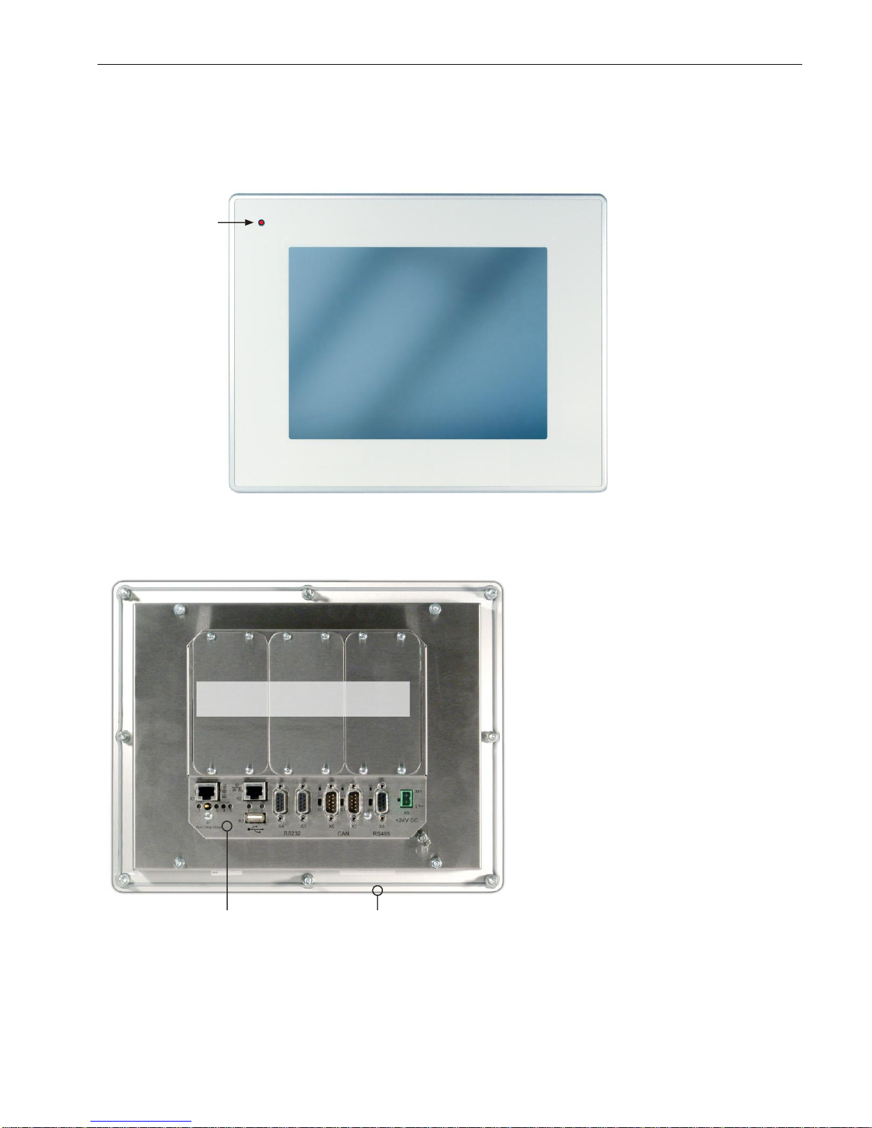
2.6.1. DC1010 Compact (CP) front view
2VF100459DG00.cdr
2.6.2. DC1010 Compact (CP) rear view
2VF100460DG01.cdr
LED (red) optional
controlled by application
Cover interface boards
Connections Frontpanel
Page 36
USER MANUAL 1.10 | DC1000 DIALOG-CONTROLLER
Berghof Automation GmbH | Harretstrasse 1 | 72800 Eningen | www.berghof.com
DC1000_HB_en_2D0982010ZD00.docx | 2VF100107FE10.docx
36
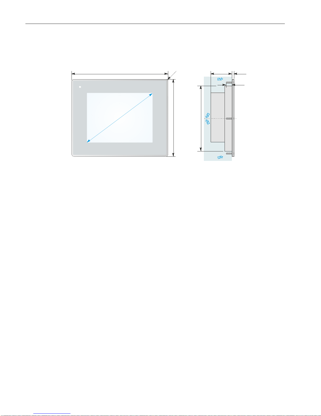
2.6.3. DC1010 Compact (CP) dimensions
2VF100461DG00.cdr
Alle Maße in [mm] / All dimensions in [mm]
313
250
max. 77
ca. 212
6
Freie Luftzirkulation
free air circulation
Freiraum / clearance > 20 mm
DC1010T T
R
8
19
G
e
w
i
n
d
e
b
o
l
z
e
n
M
5
x
2
5
m
m
t
h
r
e
a
d
e
d
b
o
l
t
1
0
,
4
"
Page 37
USER MANUAL 1.10 | DC1000 DIALOG-CONTROLLER
Berghof Automation GmbH | Harretstrasse 1 | 72800 Eningen | www.berghof.com
2VF100107FE10.docx | DC1000_HB_en_2D0982010ZD00.docx
37
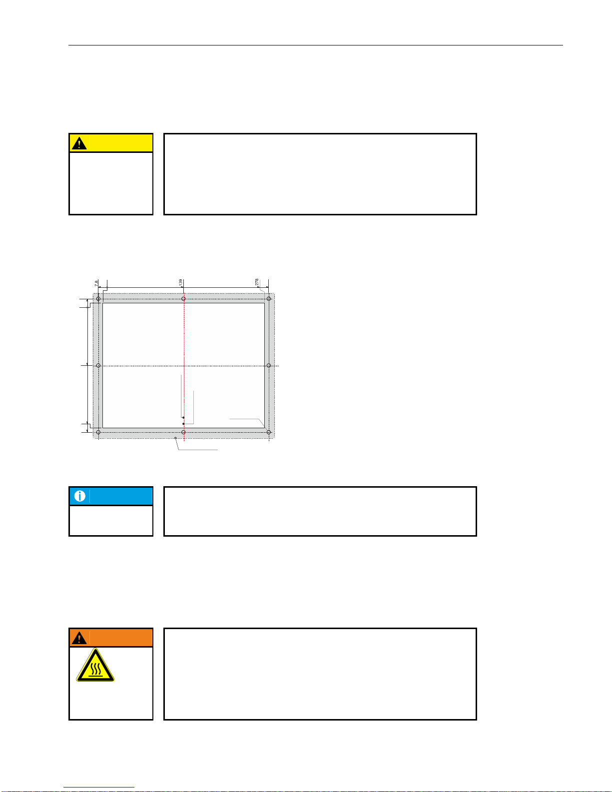
2.6.4. DC1010 Compact (CP) panel cutout
CAUTION
Installation instruction:
Only install the Dialog-Controller on a level surface!
The support points on the Dialog-Controller may not deviate from one another
by more than +/-0.5 mm. If the Dialog-Controller is nonetheless mounted on a
base which is not level, mechanical tension can result in cracks in the front
panel!
The Dialog-Controller is intended for front installation. A square panel cutout is required. The support material thickness may not exceed 6 mm.
2VF100462DG02.cdr
NOTICE
In a customized design this device is also with M5 mounting bolts. These bolts
require a bore diameter of 6 mm.
2.6.5. Mounting regulation DC1010 Compact (CP)
The Dialog-Controllers are designed for automatic convection cooling.
The Dialog-Controllers must be mounted vertically onto a metallic mounting plate.
WARNING
Danger of overheating and fire!
The Dialog-Controller may be destroyed even at a permissible ambient temperature if the convection cooling cannot function because it is built-in.
It must therefore be installed vertically and the upper and lower housing apertures must not be covered over!
DANGER OF
OVERHEATING
AND FIRE!
0
285,8
Bohrungen /
5 mm (8x)
drills
Ø
0
7,5
107,5
Mittelachse Frontplatte
centerline of front panel
Mittelachse Ausschnitt
centerline of front panel cut out
Alle Maße in [mm] / All dimensions in [mm] Frontansicht
Front view
Fronttafel-Ausschnitt
278 x 215
front panel cut out
Frontrahmen / front frame
313 x 250
215
222,5
Vertical
installation
Page 38
USER MANUAL 1.10 | DC1000 DIALOG-CONTROLLER
Berghof Automation GmbH | Harretstrasse 1 | 72800 Eningen | www.berghof.com
DC1000_HB_en_2D0982010ZD00.docx | 2VF100107FE10.docx
38
2.7. Technical data DC1012
Module data
Display
Diagonal measurement
12.1“
Resolution
800 x 600 pixels (VGA)
Colors
65536 (16 bit per pixel)
CPU, application memory
CPU
Freescale PowerPC 400 MHz
Program memory (Flash)
32 MB onboard / 24 MB for application
Program memory and data
memory (RAM)
128 MB onboard / 96 MB for application
Retain memory
16 kB
Development environment
CP1131 (CODESYS 2.3)
Dimensions and weights
Dimensions (WxHxD [mm])
440x300x77 (+6 mm front panel)
Weight
Approx. 6 kg
Operating conditions
Ambient temperature range
0 °C to +55 °C (if installation rule is adhered to)
Relative humidity
Max. 90 %, non-condensing
Transport, storage
Ambient temperature range
-20 °C to +70 °C
Relative humidity
Max. 90 %, non-condensing
Shock resistance
Vibration
Sinusoidal (EN 60068-2-6) test: Fc
10 … 150 Hz, 1 G (operation mode)
Shock resistance
15 G (approx. 150 m/s2); duration:10 ms;
semi-sinusoidal (EN 60068-2-27) test: Ea
EMC, protection type
Interference emission
EN 61000-6-4, industrial environments
Interference resistance
EN 61000-6-2, industrial environments
Protection class
III
Insulating resistance
EN 61131-2; DC 500 V test voltage
Protection type
IP20 (front: IP65)
Page 39
USER MANUAL 1.10 | DC1000 DIALOG-CONTROLLER
Berghof Automation GmbH | Harretstrasse 1 | 72800 Eningen | www.berghof.com
2VF100107FE10.docx | DC1000_HB_en_2D0982010ZD00.docx
39
Module data
Power supply (24 V power pack)
Supply voltage
+24 VDC (-15 % / +20 %) SELV,
max. alternating component: 5 %,
max. voltage interruption 1 ms (10 ms only with power supply after
61131-2)
Current consumption
Typically 1.0 A; max. 2.0 A at +24 VDC;
Fusing depending on the I/O load, max. 12 A
Polarity reversal protection
Yes
Potential isolation
Yes, between CAN bus and I/Os.
Ethernet port
Number / interface type
1 x 10/100 Base-T
Connection method
RJ45
USB ports
Number / interface types
1 x host USB, Rev. 1.1 (on rear)
2 x host USB, Rev. 1.1 (on front)
Plug/unplug cycles
Max. 1,000
CAN bus ports
Number / interface types
2 x Standard CAN ISO 11898
Potential isolation
CAN0 (X6) potential isolated
Transmission rate
Max. 1 Mbit/s
Terminating resistor
Switchable
Serial ports
Number / interface types
2 x RS232
1 x RS485
Potential isolation
RS485 (X8) potential isolated
Terminating resistor
Switchable with the RS485
E-bus port
Interface type
I/O expansion bus for up to 7 E-bus subscribers
Expansion slots
Number / interface types
3 slots for 3 I/O modules or 2 I/O modules and one AnyBus® module
Further features
Real-time clock
Yes, battery backed.
SD card
1 SD card slot or RS232 (X5)
Page 40
USER MANUAL 1.10 | DC1000 DIALOG-CONTROLLER
Berghof Automation GmbH | Harretstrasse 1 | 72800 Eningen | www.berghof.com
DC1000_HB_en_2D0982010ZD00.docx | 2VF100107FE10.docx
40
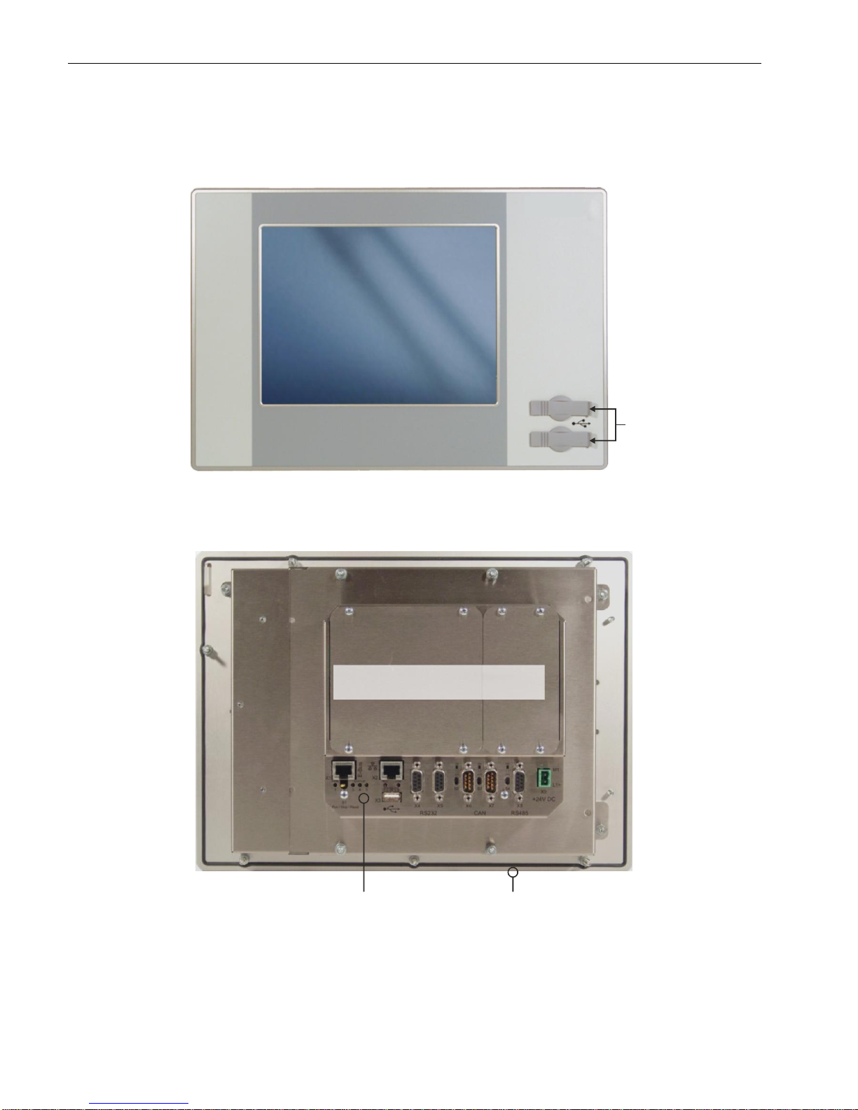
2.7.1. DC1012 Front view
2VF100272DG01.cdr
2.7.2. DC1012 Rear view
2VF100242DG01.cdr
Front-USB
Cover interface boards
Connections
Frontpanel
Page 41
USER MANUAL 1.10 | DC1000 DIALOG-CONTROLLER
Berghof Automation GmbH | Harretstrasse 1 | 72800 Eningen | www.berghof.com
2VF100107FE10.docx | DC1000_HB_en_2D0982010ZD00.docx
41
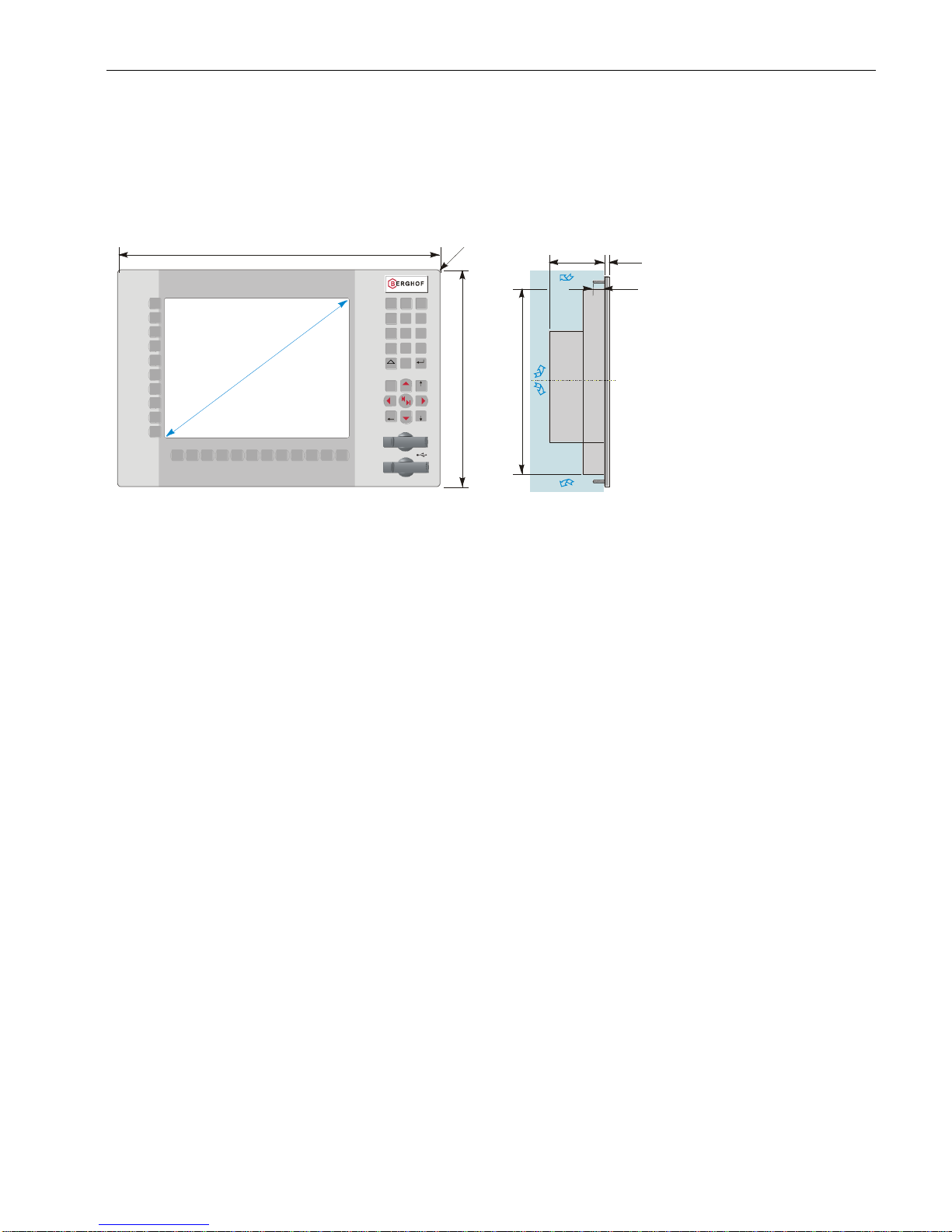
2.7.3. DC1012 Dimensions
Dimensions are identical for units equipped with either a keyboard or a touchpad.
2VF100270DG01.cdr
max. 77
ca. 270
6
Freie Luftzirkulation
free air circulation
Freiraum / clearance > 20 mm
16
G
e
w
i
n
d
e
b
o
l
z
e
n
M
4
x
1
6
m
m
t
h
r
e
a
d
e
d
b
o
l
t
BkSp
PgUp
Pos1
PgDn
7
0
.
1 2 3
Ctrl
6
98
54
EnterShift
_
F2
F3 F4 F5 F6 F7 F8 F9 F11
F10 F12
F1
S2
S3
S4
S5
S6
S7
S8
S9
S10
S1
Alle Maße in [mm] / All dimensions in [mm]
440
300
1
2
,
1
"
DC1012T K
R
8
Page 42
USER MANUAL 1.10 | DC1000 DIALOG-CONTROLLER
Berghof Automation GmbH | Harretstrasse 1 | 72800 Eningen | www.berghof.com
DC1000_HB_en_2D0982010ZD00.docx | 2VF100107FE10.docx
42
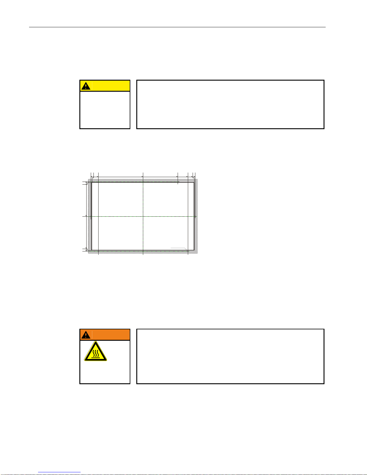
2.7.4. DC1012 Panel cutout
CAUTION
Installation instruction:
Only install the Dialog-Controller on a level surface!
The support points on the Dialog-Controller may not deviate from one another
by more than +/-0.5 mm. If the Dialog-Controller is nonetheless mounted on a
base which is not level, mechanical tension can result in cracks in the front
panel!
The Dialog-Controller is intended for front installation. A square panel cutout is required. The support material thickness may not exceed 6 mm. The panel cutouts are identical for units equipped with either a keyboard or a touch panel.
2VF100271DG00.cdr
2.7.5. Mounting regulation DC1012
The Dialog-Controllers are designed for automatic convection cooling.
The Dialog-Controllers must be mounted vertically onto a metallic mounting plate.
WARNING
Danger of overheating and fire!
The Dialog-Controller may be destroyed even at a permissible ambient temperature if the convection cooling cannot function because it is built-in.
It must therefore be installed vertically and the upper and lower housing apertures must not be covered over!
DANGER OF
OVERHEATING
AND FIRE!
Vertical
installation
Alle Maße in [mm] / All dimensions in [mm]
Frontansicht
Front view
4
0
-136
-272
-276
-4
0
26
206
346
386
412
416
Bohrungen /
5 mm (8x)
drills
Ø
Fronttafel-Ausschnitt
412 x 272 [mm]
Front panel cut-out
Page 43
USER MANUAL 1.10 | DC1000 DIALOG-CONTROLLER
Berghof Automation GmbH | Harretstrasse 1 | 72800 Eningen | www.berghof.com
2VF100107FE10.docx | DC1000_HB_en_2D0982010ZD00.docx
43
2.8. Technical data DC1012 Compact (CP)
Module data
Display
Diagonal measurement
12.1“
Resolution
800 x 600 pixels (VGA)
Colors
65536 (16 bit per pixel)
CPU, application memory
CPU
Freescale PowerPC 400 MHz
Program memory (Flash)
32 MB onboard / 24 MB for application
Program memory and data
memory (RAM)
128 MB onboard / 96 MB for application
Retain memory
16 kB
Development environment
CP1131 (CODESYS 2.3)
Dimensions and weights
Dimensions (WxHxD [mm])
360x260x77 (+6 mm front panel)
Weight
Approx. 6 kg
Operating conditions
Ambient temperature range
0 °C to +55 °C (if installation rule is adhered to)
Relative humidity
Max. 90 %, non-condensing
Transport, storage
Ambient temperature range
-20 °C to +70 °C
Relative humidity
Max. 90 %, non-condensing
Shock resistance
Vibration
Sinusoidal (EN 60068-2-6) test: Fc
10 … 150 Hz, 1 G (operation mode)
Shock resistance
15 G (approx. 150 m/s2); duration:10 ms;
semi-sinusoidal (EN 60068-2-27) test: Ea
EMC, protection type
Interference emission
EN 61000-6-4, industrial environments
Interference resistance
EN 61000-6-2, industrial environments
Protection class
III
Insulating resistance
EN 61131-2; DC 500 V test voltage
Protection type
IP20 (front: IP65)
Page 44

USER MANUAL 1.10 | DC1000 DIALOG-CONTROLLER
Berghof Automation GmbH | Harretstrasse 1 | 72800 Eningen | www.berghof.com
DC1000_HB_en_2D0982010ZD00.docx | 2VF100107FE10.docx
44
Module data
Power supply (24 V power pack)
Supply voltage
+24 VDC (-15 % / +20 %) SELV,
max. alternating component: 5 %,
max. voltage interruption 1 ms (10 ms only with power supply after
61131-2)
Current consumption
Typically 1.0 A; max. 2.0 A at +24 VDC;
Fusing depending on the I/O load, max. 12 A
Polarity reversal protection
Yes
Potential isolation
Yes, between CAN bus and I/Os.
Ethernet port
Number / interface type
1 x 10/100 Base-T
Connection method
RJ45
USB ports
Number / interface types
1 x host USB, Rev. 1.1 (on rear)
Plug/unplug cycles
Max. 1,000
CAN bus ports
Number / interface types
2 x Standard CAN ISO 11898
Potential isolation
CAN0 (X6) potential isolated
Transmission rate
Max. 1 Mbit/s
Terminating resistor
Switchable
Serial ports
Number / interface types
2 x RS232
1 x RS485
Potential isolation
RS485 (X8) potential isolated
Terminating resistor
Switchable with the RS485
E-bus port
Interface type
I/O expansion bus for up to 7 E-bus subscribers
Expansion slots
Number / interface types
3 slots for 3 I/O modules or 2 I/O modules and one AnyBus® module
Further features
Real-time clock
Yes, battery backed.
SD card
1 SD card slot or RS232 (X5)
Page 45
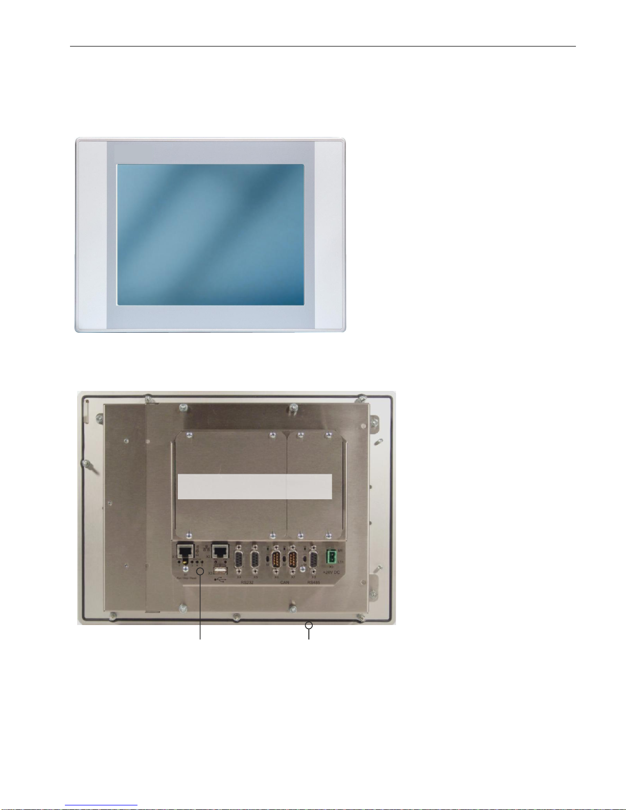
USER MANUAL 1.10 | DC1000 DIALOG-CONTROLLER
Berghof Automation GmbH | Harretstrasse 1 | 72800 Eningen | www.berghof.com
2VF100107FE10.docx | DC1000_HB_en_2D0982010ZD00.docx
45
2.8.1. DC1012 Compact (CP) front view
2VF100473DG01.cdr
2.8.2. DC1012 Compact (CP) rear view
2VF100242DG01.cdr
Cover interface boards
Connections
Frontpanel
Page 46
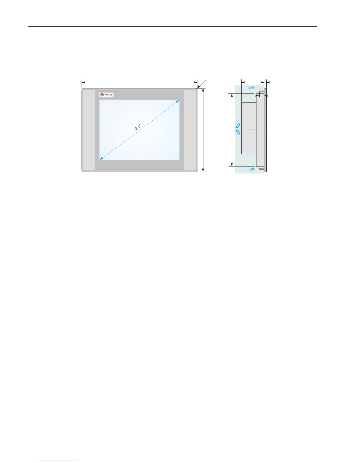
USER MANUAL 1.10 | DC1000 DIALOG-CONTROLLER
Berghof Automation GmbH | Harretstrasse 1 | 72800 Eningen | www.berghof.com
DC1000_HB_en_2D0982010ZD00.docx | 2VF100107FE10.docx
46
2.8.3. DC1012 Compact (CP) dimensions
2VF100474DG00.cdr
Alle Maße in [mm] / All dimensions in [mm]
360
260
max. 77
ca. 226
6
Freie Luftzirkulation
free air circulation
Freiraum / clearance > 20 mm
DC1012T T CP
R 8
16
G
e
w
i
n
d
e
b
o
l
z
e
n
M
4
x
2
2
m
m
t
h
r
e
a
d
e
d
b
o
l
t
Page 47
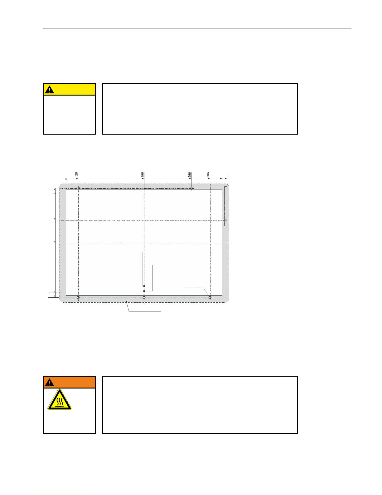
USER MANUAL 1.10 | DC1000 DIALOG-CONTROLLER
Berghof Automation GmbH | Harretstrasse 1 | 72800 Eningen | www.berghof.com
2VF100107FE10.docx | DC1000_HB_en_2D0982010ZD00.docx
47
2.8.4. DC1012 Compact (CP) panel cutout
CAUTION
Installation instruction:
Only install the Dialog-Controller on a level surface!
The support points on the Dialog-Controller may not deviate from one another
by more than +/-0.5 mm. If the Dialog-Controller is nonetheless mounted on a
base which is not level, mechanical tension can result in cracks in the front
panel!
The Dialog-Controller is intended for front installation. A square panel cutout is required. The support material thickness may not exceed 6 mm.
2VF100475DG00.cdr
2.8.5. Mounting regulation DC1012 Compact (CP)
The Dialog-Controllers are designed for automatic convection cooling.
The Dialog-Controllers must be mounted vertically onto a metallic mounting plate.
WARNING
Danger of overheating and fire!
The Dialog-Controller may be destroyed even at a permissible ambient temperature if the convection cooling cannot function because it is built-in.
It must therefore be installed vertically and the upper and lower housing apertures must not be covered over!
DANGER OF
OVERHEATING
AND FIRE!
0
332
Bohrungen /
5 mm (6x)
drills
Ø
0
4
Mittelachse Frontplatte
centerline of front panel
Mittelachse Ausschnitt
centerline of front panel cut out
Alle Maße in [mm] / All dimensions in [mm] Frontansicht / Front view
Fronttafel-Ausschnitt
332 x 232
front panel cut out
Frontrahmen / front frame
360 x 260
-232
-236
336
-116
-66
Vertical
installation
Page 48
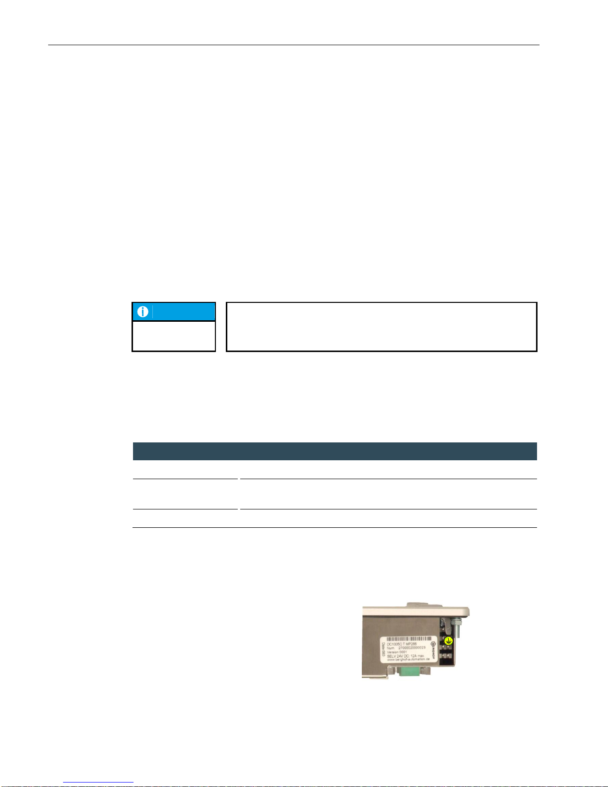
USER MANUAL 1.10 | DC1000 DIALOG-CONTROLLER
Berghof Automation GmbH | Harretstrasse 1 | 72800 Eningen | www.berghof.com
DC1000_HB_en_2D0982010ZD00.docx | 2VF100107FE10.docx
48
2.9. Mounting and connection
2.9.1. Mounting
Required tools
Box wrench, Allan key (7 mm) or open-end wrench SW
Securing
The Dialog-Controller is equipped with approx. 15 mm-long, M 4, welded-on stud bolts. The unit is secured
using U washers, spring washers/lock washers and nuts (M 4).
Remove the shipping nuts and washers.
Push the Dialog-Controller through the panel cutout.
Secure the Dialog-Controller in the panel cutout.
Adjust the Dialog-Controller in the panel cutout and tighten all nuts.
NOTICE
Disassembly:
Follow the reverse sequence to disassemble the Dialog-Controller.
2.9.2. Connections
Power supply
Power for the Dialog-Controller comes from an external 24 VDC power supply. Before continuing with the
connection, check that the external power supply meets the required specifications.
External power supply (24 VDC)
Output voltage
+24 VDC SELV (-15 % / +20 %)
Alternating component
Max. 5 %.
The direct voltage level may not fall below 20.4 V.
Power output
Max. 2.0 A at +24 VDC at 25 °C.
Installation
All connections and wiring must be laid out to prevent any interference due to inductive or capacitive pick-up
from arising in the Dialog-Controller. The infeed lines must provide adequate current and voltage carrying
capacity.
Connect the Dialog-Controller’s housing to the ground lead
(PE) with a copper cross-section of at least 1.5 mm².
The Dialog-Controller is equipped with a 6.3 x 0.8 mm
plug-in tab for this purpose.
2VF100236DG00.cdr
Ground
PE
Page 49
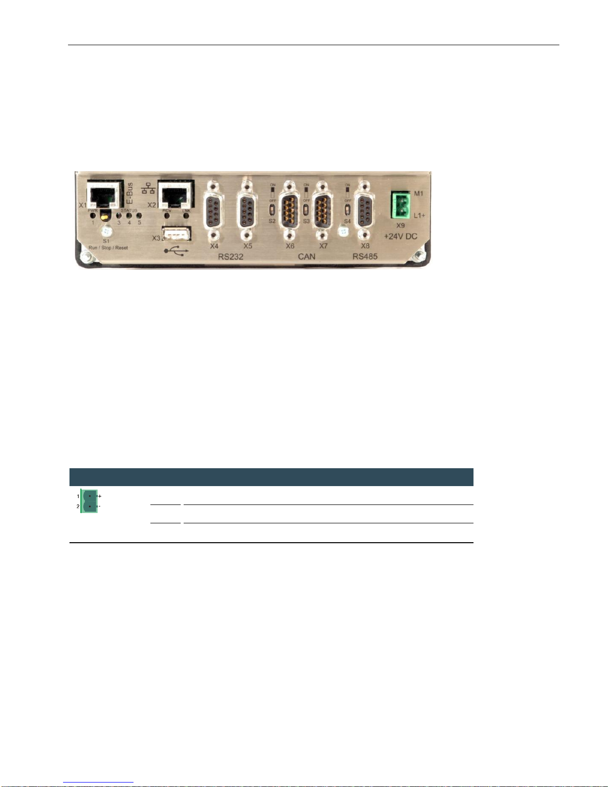
USER MANUAL 1.10 | DC1000 DIALOG-CONTROLLER
Berghof Automation GmbH | Harretstrasse 1 | 72800 Eningen | www.berghof.com
2VF100107FE10.docx | DC1000_HB_en_2D0982010ZD00.docx
49
2.10. Pin assignment
2.10.1. Pin overview
2VF100231DG00.cdr
2.10.2. Power supply
Internal power pack
A power pack to provide 24 VDC (-15 % / +20 %) input voltage is built into the Dialog-Controller. The power
pack is equipped with internal polarity reversal protection and a current at make limiter. The infeed line and
the power pack must be protected by means of an external short circuit and overload protector with a maximum of 12 A (depending on the number of I/Os).
Power buffering
The power supply unit can bridge voltage dips lasting 1 ms maximum.
X9 pin assignment
X9
Phoenix MSTB
2.5/2-G-5.08
1
external power supply 24 VDC (-15 % / +20 %)
2
external power supply GND
2.10.3. 10/100 Base-T Network Connection (Ethernet)
The onboard 10/100 Base-T Ethernet adapter with an RJ45 connector is used to connect the unit to a network. The “LNK” and “RCV” status LEDs provide information regarding a successful network link.
Page 50
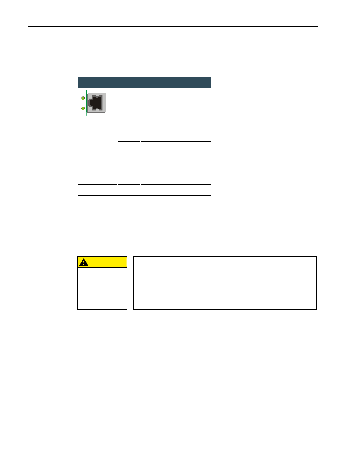
USER MANUAL 1.10 | DC1000 DIALOG-CONTROLLER
Berghof Automation GmbH | Harretstrasse 1 | 72800 Eningen | www.berghof.com
DC1000_HB_en_2D0982010ZD00.docx | 2VF100107FE10.docx
50
X2 pin assignment
X2
RJ45
1
TX+
2
TX- 3 RX+
4
75 Ω
5
75 Ω
6
RX-
7
75 Ω
8
75 Ω
“LNK” LED
green
ON – operational
“RCV” LED
green
FLASHING – data receive
2.10.4. USB
Devices equipped with USB interfaces can be connected to the two USB master ports (Rev. 1.1). The USB on
the back (X3) and the front USB (under the IP65 cover) are connected via an internal USB hub. The only USB
devices classes which can be employed for CODESYS users are USB sticks. A mouse can only be employed at
the Linux level. The following points must be taken into consideration when USB sticks are employed:
CAUTION
An USB stick may only be pulled during operation if all file operations
have been completed, otherwise the USB stick may become unusable!
If programs still have files open, the directory will no longer be able to be removed once the USB stick has been pulled. In this situation file or directory operations will result in blockages because information is to be read from a
device that is no longer available in the system. Therefore, always make sure
that no program still has open files in the USB stick before pulling the stick.
USB memory sticks with FAT/FAT32 formatting are supported.
USB memory sticks can be inserted and pulled during operation. The inserted device is automatically
detected and mounted in the /media/usbX directory. When the USB stick is pulled, the associated
/media/usbX directory automatically “disappears” provided no program is currently accessing it (see
above).
Either the first partition or, if there are no partitions, the entire memory will be mounted on the
memory stick, in other words, the associated directory appears automatically.
The first stick is mounted under /media/usb0, the second under /media/usb1, and so on. A maximum
of 8 sticks may be inserted simultaneously (/media/usb[0-7]). If a new (or previously inserted, then
pulled) stick is inserted it will be placed on the directory with the lowest number. Connecting a USB
hub allows multiple sticks to be operated at a given USB interface. Care must be taken that no USB
devices are still inserted in the hub when the hub is itself inserted or pulled.
Based on the variety and number of available USB chip and USB drive manufactures, there is no guar-
antee that every available USB drive on the market works with the device. Every USB drive has to be
Page 51
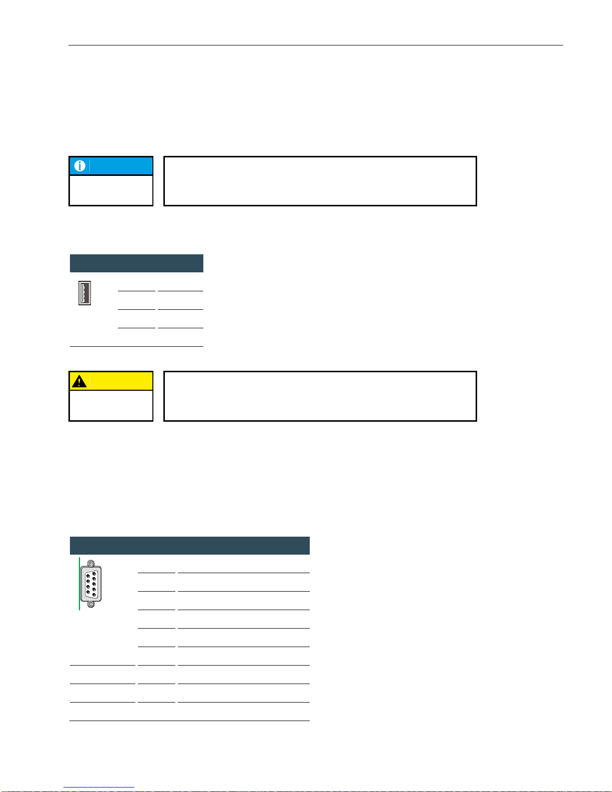
USER MANUAL 1.10 | DC1000 DIALOG-CONTROLLER
Berghof Automation GmbH | Harretstrasse 1 | 72800 Eningen | www.berghof.com
2VF100107FE10.docx | DC1000_HB_en_2D0982010ZD00.docx
51
checked if it works with the desired controller in advance. It is also recommended to use always the
newest available firmware to get the best possible results.
NOTICE
The mechanical structure of the USB port is designed for a maximum of 1,000
insertion cycles.
X3 pin assignment
X3
USB
B1
VCC
B2
D-
B3
D+
B4
GND
CAUTION
A maximum current of 0.5 A is available at the USB ports (combined)!
A device requiring more current will therefore not function and may be damaged.
2.10.5. CAN bus
The two CAN ports (CAN0/CAN1) comply with the ISO 11898 standard and can be operated up to a
maximum baud rate of 1 MBit/s. The smallest CAN baud rate that can be set is 50 kBit/s. In addition, the X6
interface (CAN0) is equipped with a potential isolation.
X6/7 pin assignment
X6/7
Sub-D9 M
1
NC (Do not connect)
2
CAN_L
3
CAN_GND
4
NC (Do not connect)
5
NC (Do not connect)
6
NC (Do not connect)
7
CAN_H
8 NC (Do not connect)
9 NC (Do not connect)
1
9
6
5
identical for the
front USB
Page 52
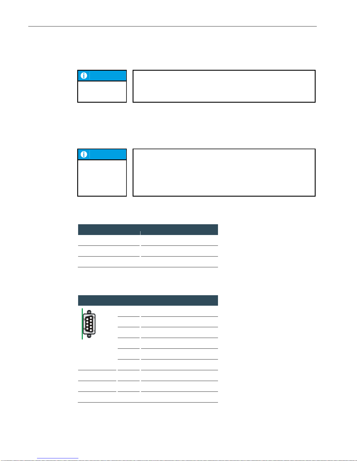
USER MANUAL 1.10 | DC1000 DIALOG-CONTROLLER
Berghof Automation GmbH | Harretstrasse 1 | 72800 Eningen | www.berghof.com
DC1000_HB_en_2D0982010ZD00.docx | 2VF100107FE10.docx
52
NOTICE
A terminating resistor can be switched using the S2 (CAN0) and S3
(CAN1) switches.
This is required if the associated CAN interface is located at the beginning or at
the end of its CAN bus topology.
2.10.6. Serial ports
In all, the module is equipped with 3 serial communications interfaces, each of which is connected using a
9-pin Sub-D socket. X8 is a potential isolated RS485 interface, while two RS232 ports are available at X4/X5.
NOTICE
The RS232 port at X4 has an exception setting!
Depending on the configuration it can be used as either a Linux console, or as
a PPP interface for remote maintenance or a CODESYS programming interface.
If the Dialog-Controller is started in the configuration mode, the device can be
configured in this mode using a serial PPP link. Here too, connection is via X4.
The interfaces in the software are addressed by the following names:
Connector
Software interface
X4
COM1
X5
COM2
X6
COM3
X4/5 pin assignment
X4/5
Sub-D9 F
1
NC (Do not connect)
2
RXD
3
TXD
4
NC (Do not connect)
5
GND
6
NC (Do not connect)
7 NC (Do not connect)
8 NC (Do not connect)
9 NC (Do not connect)
RS232
Page 53
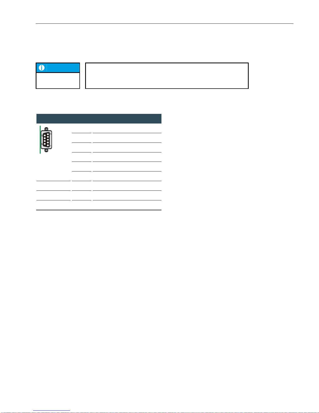
USER MANUAL 1.10 | DC1000 DIALOG-CONTROLLER
Berghof Automation GmbH | Harretstrasse 1 | 72800 Eningen | www.berghof.com
2VF100107FE10.docx | DC1000_HB_en_2D0982010ZD00.docx
53
NOTICE
If the SD card reader is activated, then the second RS232 interface (X5) is not
longer available.
X8 pin assignment
X8
Sub-D9 F
1
RTXD-
2
NC (Do not connect)
3
NC (Do not connect)
4
RTXD+
5
GND
6
NC (Do not connect)
7 NC (Do not connect)
8 NC (Do not connect)
9 NC (Do not connect)
The interface is terminated “softly” in the Dialog-Controller at 500 Ω (older devices 5 kΩ ). A 120 Ω differential terminating resistor can be activated for each S4 switch.
RS485
potential isolated
Page 54
USER MANUAL 1.10 | DC1000 DIALOG-CONTROLLER
Berghof Automation GmbH | Harretstrasse 1 | 72800 Eningen | www.berghof.com
DC1000_HB_en_2D0982010ZD00.docx | 2VF100107FE10.docx
54
NOTICE
For using the symmetrical terminating resistor (S4) on the inoperative
bus:
On an inoperative bus the terminating resistor causes a qualitatively unstable signal state, which can give rise to faulty received data.
Background information:
Thanks to the differential signal transmission the RS485 interface achieves a
high signal-to-noise ratio and facilitates high data rates and great ranges. An
operative bus with defined states - logical ‘1’ (A-B < -0.2 V) or logical ‘0’ (A-B >
+0.2 V) - is prerequisite for a high symmetrical signal-to-noise ratio. In an inoperative bus the signals highly resistive and hence susceptible to interference.
Thanks to the terminating resistor, which can be activated, a signal state is
produced with a low voltage difference between lines A and B.
There are two measures which can prevent this state:
An appropriate log ensures that one of the bus subscribers operates the
bus actively at all times.
If the state of the inoperative bus is to be kept under control, a sufficient
signal-to-noise ratio must be established by means of an asymmetric bus
termination (at the same time reducing the symmetrical signal-to-noise
ratio). With a suitable resistance network as the line termination, a voltage
difference between the signals can be produced in an inoperative state.
Generally speaking, it is impossible to specify favorable dimensioning because it is affected by the length of the bus and transmission rates. By
way of example, reference is made to the line termination in the case of
the Profibus.
NOTICE
How to connect "GND":
Despite differential signal transmission, depending on the topology and
length of the connected lines, it may be imperative to connect ground
reference (GND) may be imperative!
The longer the line the greater the potential differences between bus subscribers may be. In such cases, despite potential isolation, common-mode interference may exceed voltage limits, causing differential signal interference and
hence a functional disorder. It is urgently advised to carry along the “GND” si gnal for potentially isolated interfaces, with a connection to the reference ground
in one spot. An attenuating connection, for example via 200 Ω at multi-ple
points on the bus.
Page 55
USER MANUAL 1.10 | DC1000 DIALOG-CONTROLLER
Berghof Automation GmbH | Harretstrasse 1 | 72800 Eningen | www.berghof.com
2VF100107FE10.docx | DC1000_HB_en_2D0982010ZD00.docx
55
2.10.7. E-bus
The E-bus (X1) allows up to 7 E-bus subscribers to be connected to the Dialog-Controller. Please note that,
due to their function, some E-bus modules represent 2 E-bus subscribers, e.g., QDIO-E 16/16/Z2.
Cable
Type
Ethernet patch cable; 1:1 assignment (not crossed)
Lead cross-section
At least 0.22 mm2
Category
CAT.5
Length
Max. 7 m
CAUTION
The Dialog-Controller makes a max. current of 0.5 A available for E-bus
modules!
As a rule, this is sufficient current to supply 7 E-bus modules. However, should
this current consumption level be exceeded, the E-bus and the connected
modules may become nonfunctioning!
Therefore, please note the current consumption of all E-bus modules and all
connected consumers as a whole. In some instances, connection of consuming
devices, e.g., an encoder can result in the current limit being exceeded.
Wherever possible you should only employ consumer devices with as low a
current requirement as possible!
2.10.8. Connections for expansion ports
NOTICE
Device connection
Prior to connecting any external devices, please carefully read the documentation included with these devices.
Always hold a lead by the plug when connecting or disconnecting a device.
Never pull on the lead itself!
The connection level for all external devices is located on the rear of the Dialog-Controller. All connections
are plug-in.
Page 56
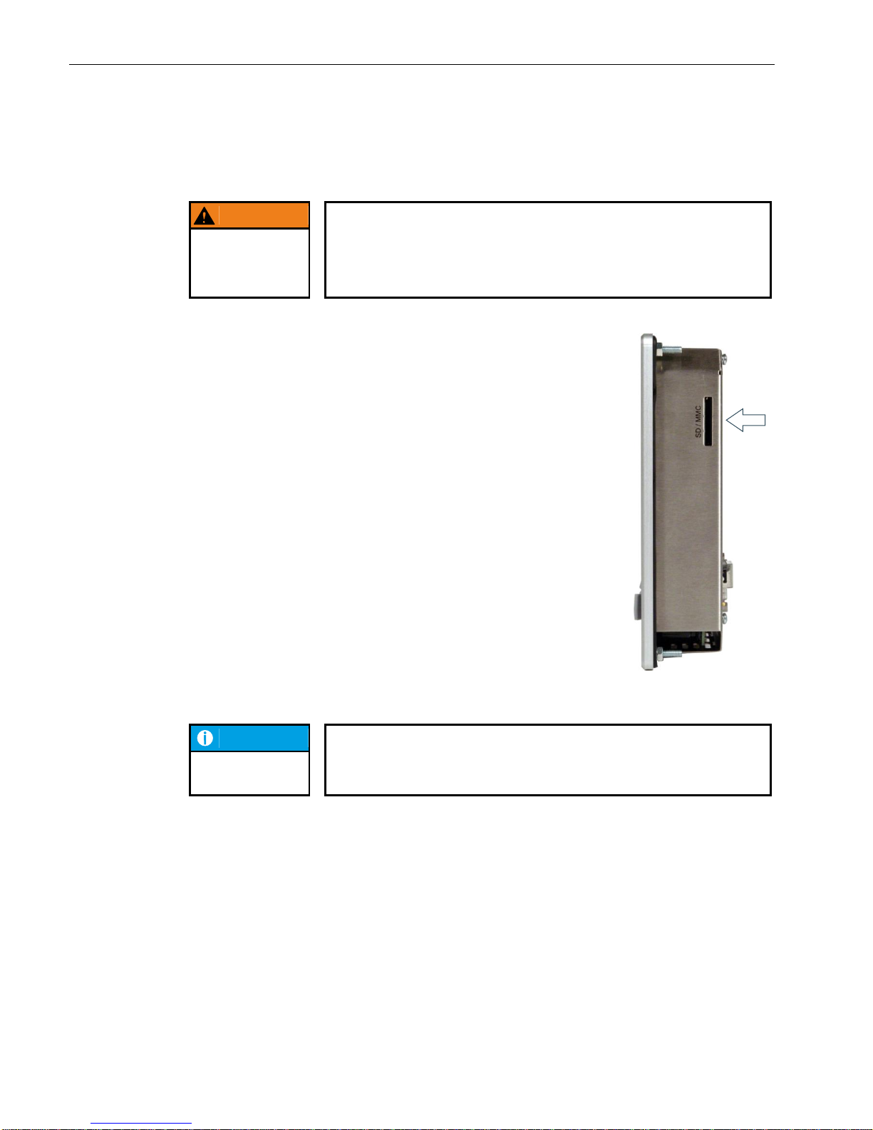
USER MANUAL 1.10 | DC1000 DIALOG-CONTROLLER
Berghof Automation GmbH | Harretstrasse 1 | 72800 Eningen | www.berghof.com
DC1000_HB_en_2D0982010ZD00.docx | 2VF100107FE10.docx
56
2.11. SD card
WARNING
The SD card must not be plugged in or unplugged while the DialogController is operating as this would result in functional errors with the
Dialog-Controller!
The SD card may only be installed or removed when the Dialog-Controller has
been switched off!
The SD card drive is equipped with a push-in/push-out insert and eject mechanism. Gold plated contacts ensure low contact resistance and a service life of up
to 10,000 plug-in/unplug cycles.
The write protection switch on the SD card is currently not recognized.
The SD card drive must be activated via the web configuration. In this case the
application can no longer access the second serial port (SIO2/X5). The files on
the SD drive can be written to, read from as well as copied. Access to the drive is
along the following path: /media/sd.
At present data memory cards with a memory capacity of up to 1 GB can be
used.
2VF100312DG01.cdr
NOTICE
If the SD card reader is activated, then the second RS232 interface (X5) is not
longer available.
Page 57
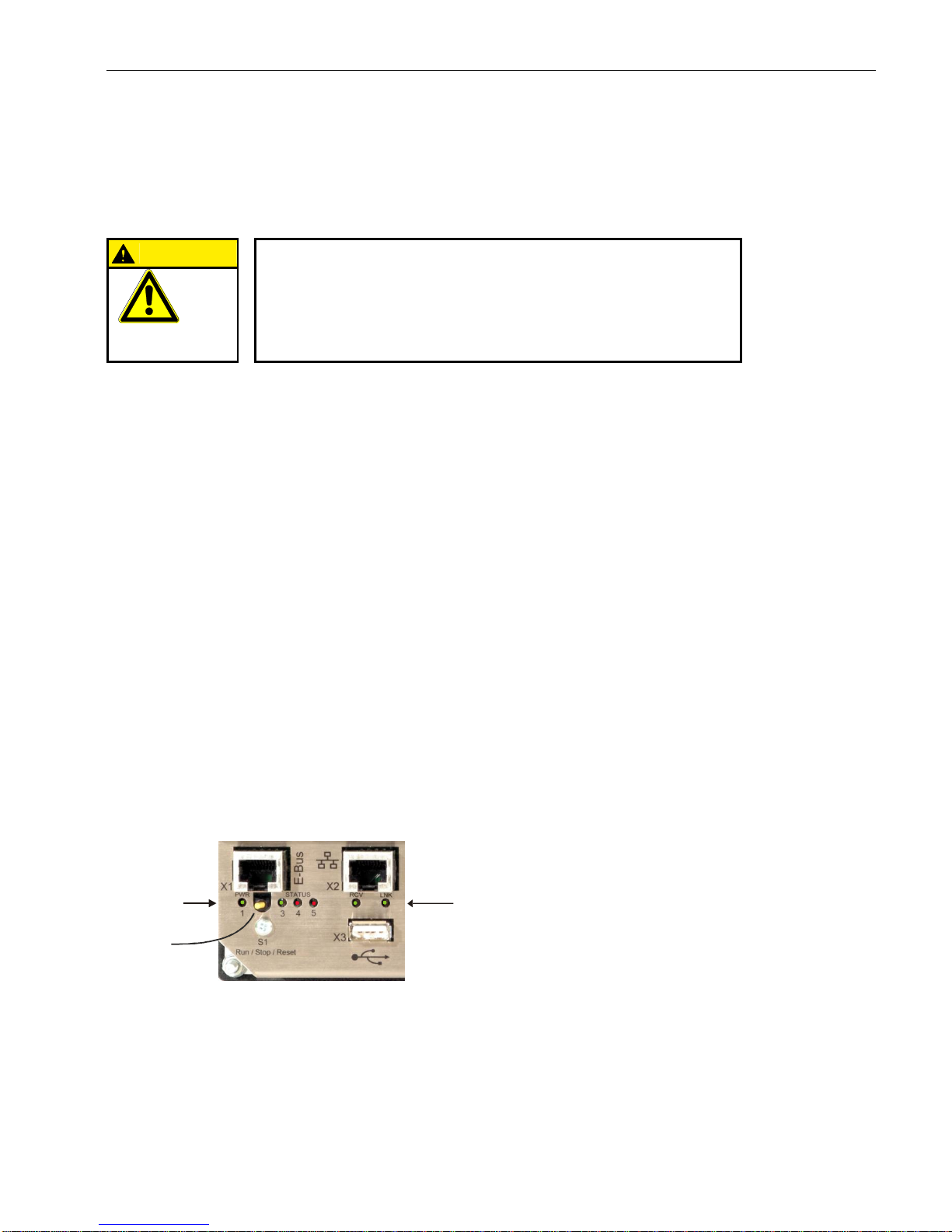
USER MANUAL 1.10 | DC1000 DIALOG-CONTROLLER
Berghof Automation GmbH | Harretstrasse 1 | 72800 Eningen | www.berghof.com
2VF100108FE04.docx | DC1000_HB_en_2D0982010ZD00.docx
57
3. Dialog-Controller operation
CAUTION
Never plug in, apply, disconnect or touch connections while the device is
operating!
This could result in malfunction or destruction of the device. Before working on
the modules, always switch all infeeds to them off; including infeeds from connected peripheral devices such as remote-feed encoders, programming devices, etc.
MALFUNCTION
3.1. Commissioning
Before applying the supply voltage, recheck all connections to ensure they are properly wired and have the
correct polarity.
Switching on
The Dialog-Controller is not equipped with its own main power switch. The Dialog-Controller starts when the
associated equipment is switched on or when the power supply is connected.
Switching off
The Dialog-Controller switches off when the associated equipment is switched off or the power supply is disconnected.
3.2. Function selection, indicators, diagnostics
3.2.1. Status indicators
The function of the status indicators frequently depends on the software development environment employed on the Dialog-Controller.
CP1131-P: PLC programming using CODESYS and Berghof Target Support Package
CPC++: C programming directly on the LINUX operating system
2VF100232DG00.cdr
S1
Status-LED Ethernet Status-LED
Page 58
USER MANUAL 1.10 | DC1000 DIALOG-CONTROLLER
Berghof Automation GmbH | Harretstrasse 1 | 72800 Eningen | www.berghof.com
DC1000_HB_en_2D0982010ZD00.docx | 2VF100108FE04.docx
58
Operating mode selection switch (S1)
Used to change the operating mode and for module restart.
Switch position
CP1131-P
CPC++
RUN
CP1131-P program in the RUN mode. Can be
changed with the programming device.
Freely programmable
STOP
CP1131-P program in the STOP mode.
Freely programmable
RESET
CP1131-P program is restarted with deleted
variables (RETAIN variables are not deleted).
Freely programmable
Status LED
Four operating status LEDs provide information about the current status of the power supply, the module
mode as well as fault and error messages.
LED
Logical state
1
PWR (green)
ON = Correct supply voltage to the module electronics
Status LEDs for CP1131-P programs
Status 3 (green)
Status 4 (red)
Status 5 (red)
Description
on
off
any
Application program
status: RUN
off
on
any
Application program
status: STOP
off
flashing
any
Application program
status: ERROR STOP
flashing
on
any
Application program
status: Breakpoint STOP
any
any
on
CP1131 mode: FORCE
Basic recovery procedure in case of an ERROR STOP:
determine the cause of the error (indicated in the service menu on the display or can be read using a
web browser)
correct the cause of the error
perform a controller reset; or alternatively: Mode selection switch / Service menu / CODESYS/ web
browser
return the controller to operation
Page 59
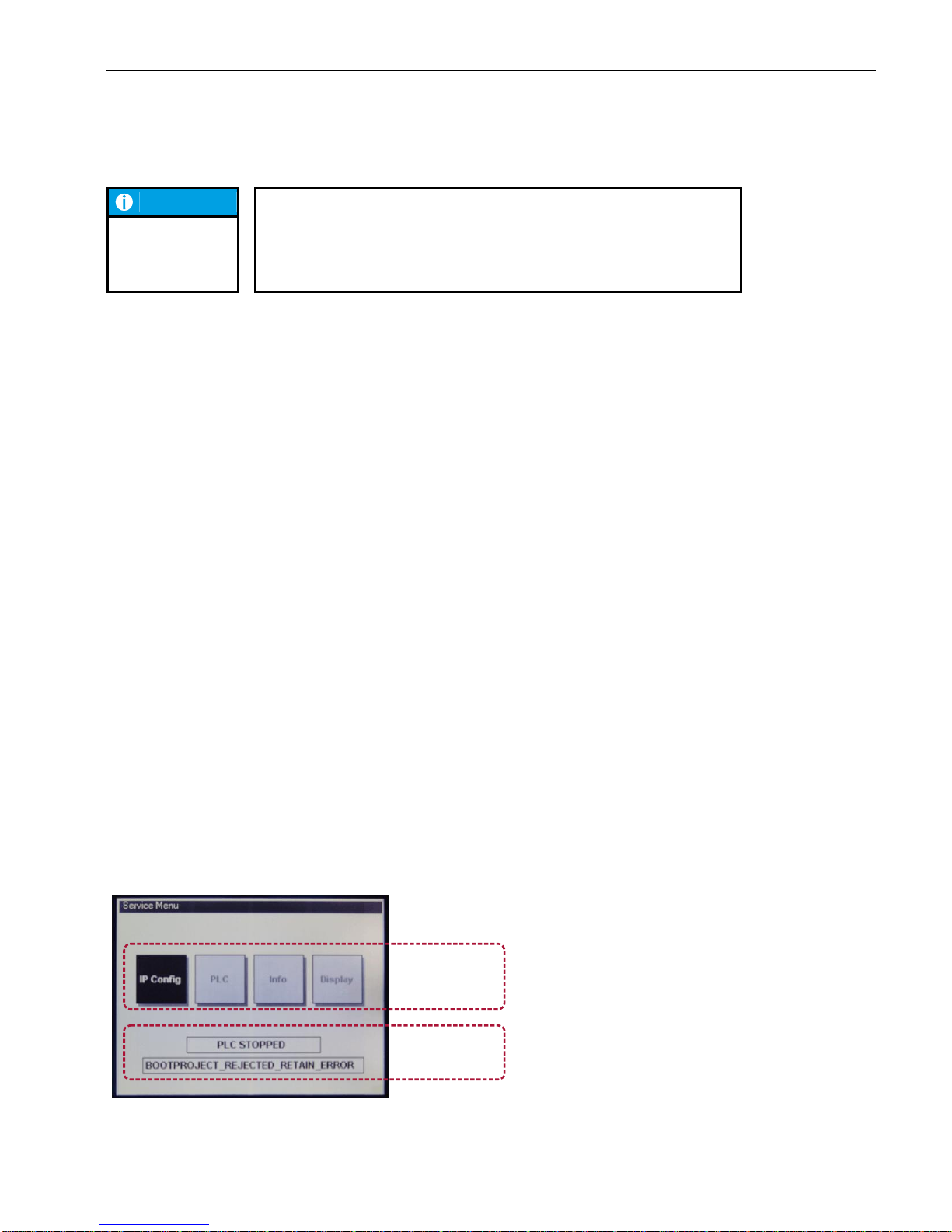
USER MANUAL 1.10 | DC1000 DIALOG-CONTROLLER
Berghof Automation GmbH | Harretstrasse 1 | 72800 Eningen | www.berghof.com
2VF100108FE04.docx | DC1000_HB_en_2D0982010ZD00.docx
59
NOTICE
CP1131-P FORCE mode:
FORCE indicates that the application program is running and CODESYS forces a value to be written to at least one variable at the start of every cycle. This
makes it evident to the user that the application program might react differently
if no such forced access to the PLC program’s process were to occur.
Status LEDs for CPC++ programs
LEDs 3 to 5 can each be separately controlled by application software.
Ethernet status LED
Refer to the section “10/100 Base T Network Connection (Ethernet)”.
3.3. Service menu
Functional scope
The Dialog-Controller’s service menu allows the user to define and examine device and communications parameters as well as device states. It also represents a valuable service and commissioning aid. The service
menu thus permits setting definition at the Ethernet interface and diagnostics functions in case of errors to
be simplified and accelerated.
The service menu has a two-part structure:
Parameter window
The following four menu items are displayed here. Each menu item can contain additional subject-related
submenu items.
Config
PLC
Info
Display
PLC window
Up to two lines reflecting the current PLC status can be displayed. Line 1 will always be visible, while line 2
will only appear when an error occurs.
2VF100273DG01.cdr
PLC window
Parameter window
Basic structure
Page 60
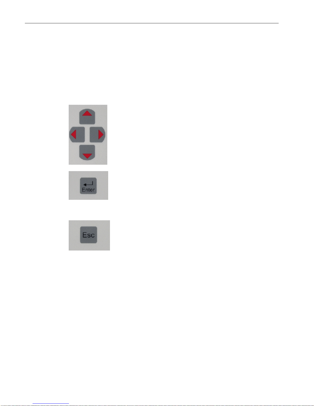
USER MANUAL 1.10 | DC1000 DIALOG-CONTROLLER
Berghof Automation GmbH | Harretstrasse 1 | 72800 Eningen | www.berghof.com
DC1000_HB_en_2D0982010ZD00.docx | 2VF100108FE04.docx
60
3.3.1. Using the service menu
Touch screen
In Dialog-Controllers with a built-in touch screen, the service menu can be operated directly via screen input.
Keyboard
If the Dialog-Controller is equipped with a keyboard, the following keys are used to operate the service menu:
The cursor block is used to navigate between the individual menu items on a given menu level.
The [Enter] key is used to confirm an input.
If a submenu permits values to be modified, this modification is performed with the [Enter] key. The [+] / [-] keys
do not function in the service menu. However, using the
cursor block, you can navigate to a “+/-” symbol displayed
on the screen, then use the [Enter] key to either increment
or decrement the associated value.
The [Esc] key is used to exit a menu without saving any
changes which may have been made.
3.3.2. Parameter window
Checking and setting options are accessed through this window section.
The following four menu items are available for selection:
Config to check and adjust Ethernet parameters, system time and the COM1 serial interface (X4).
PLC to check and operate the PLC.
Info to display the hardware and software version levels as well as diagnostic data; and it also offers
the save function (USB, SD, Flash).
Display to adjust contrast values.
Cursor block
[Enter] key
[Esc] key
Parameter
window structure
Page 61
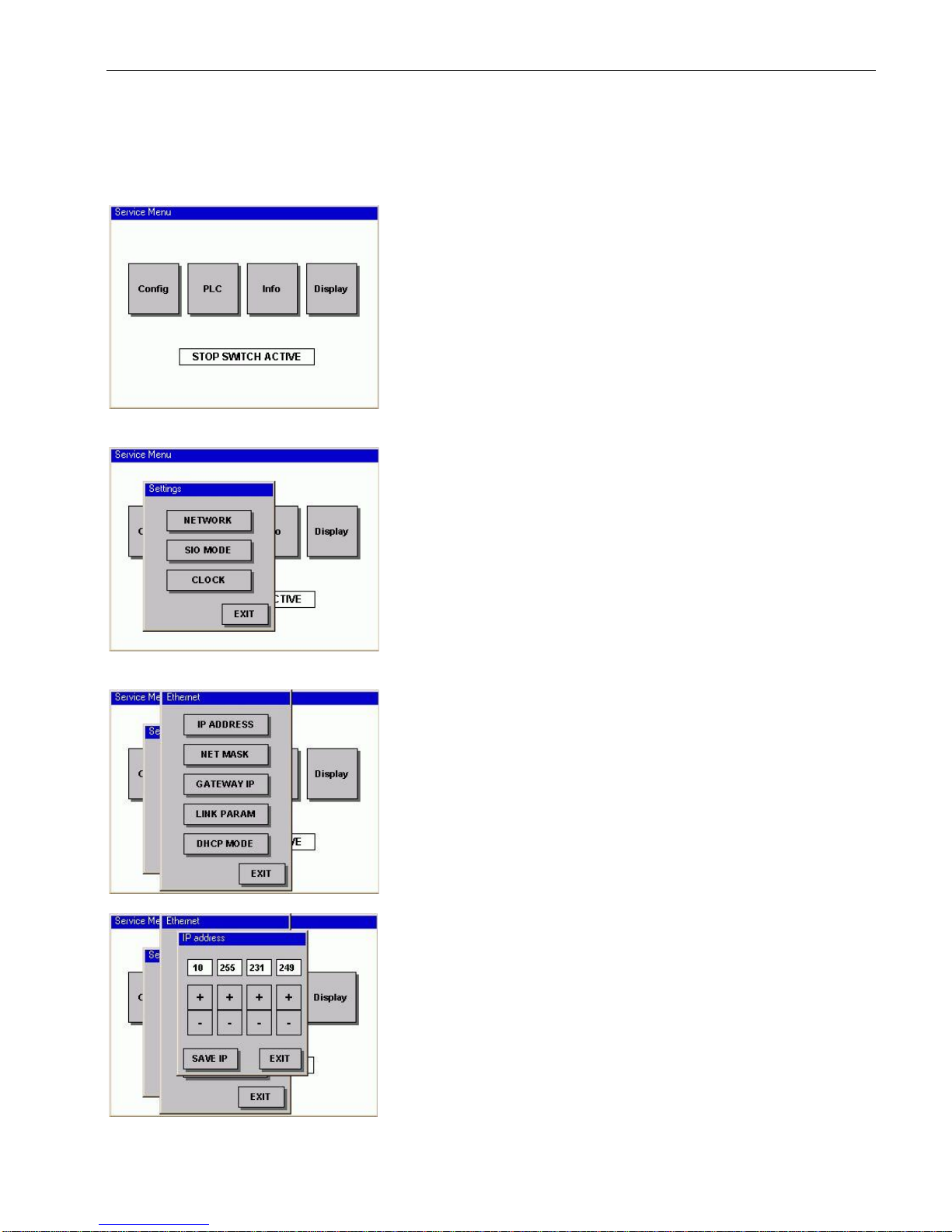
USER MANUAL 1.10 | DC1000 DIALOG-CONTROLLER
Berghof Automation GmbH | Harretstrasse 1 | 72800 Eningen | www.berghof.com
2VF100108FE04.docx | DC1000_HB_en_2D0982010ZD00.docx
61
“Config” service menu
Check and adjust the parameters.
Check and adjust Ethernet parameters.
Check and adjust the IP address.
IP address:
The “+/-” keys can be used to adjust and set each individual IP address byte. The “Save IP” button is then used
to save the settings. New settings will only take effect after
a restart! The “EXIT” button allows you to leave the menu
without saving any changes which may have been made.
Config
NETWORK
Ethernet
“IP ADDRESS”
Page 62
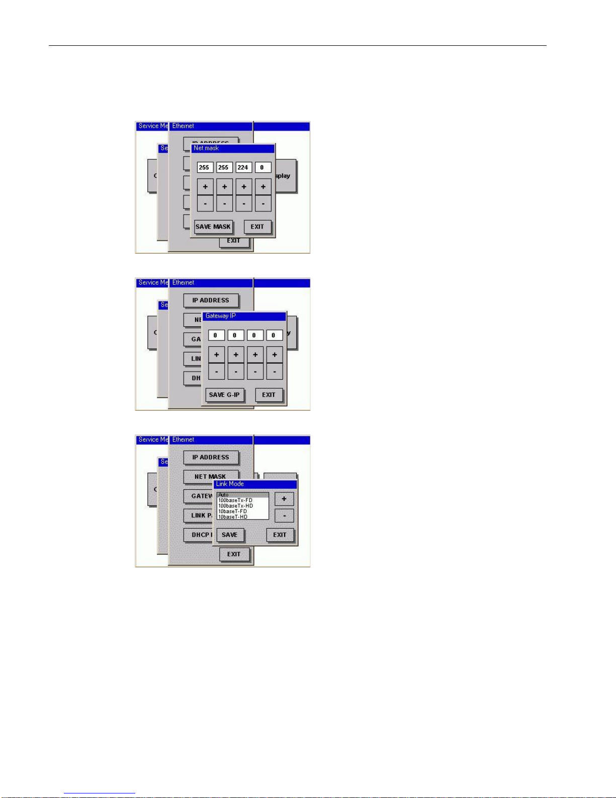
USER MANUAL 1.10 | DC1000 DIALOG-CONTROLLER
Berghof Automation GmbH | Harretstrasse 1 | 72800 Eningen | www.berghof.com
DC1000_HB_en_2D0982010ZD00.docx | 2VF100108FE04.docx
62
Check and adjust the network mask.
Net mask:
The “+/-” keys can be used to adjust and set each individual network mask byte. The “Save Mask” button is then
used to save the settings. New settings will only take effect
after a restart! The “EXIT” button allows you to leave the
menu without saving any changes which may have been
made.
Check and adjust the gateway IP address.
Gateway IP:
The “+/-” keys can be used to adjust and set each individual gateway IP address byte. The “Save G-IP” button is
then used to save the settings. New settings will only take
effect after a restart! The “EXIT” button allows you to
leave the menu without saving any changes which may
have been made.
Check and adjust the communications parameters.
Link Mode:
Auto: Automatic parameter setting negotiated among the
communications parameters (default setting). The default
settings should only be changed under special circumstances (e.g. communications problems).
100base-Tx-FD: 100 MBit/s, full duplex
100base-Tx-HD: 100 MBit/s, half duplex
10base-T-FD: 10 MBit/s, full duplex
10base-T-HD: 10 MBit/s, half duplex
The “Save” button is used to save the new setting. New
settings will only take effect after a restart! The “EXIT”
button allows you to leave the menu without saving any
changes which may have been made.
Ethernet
“Net mask”
Ethernet
“Gateway IP”
Ethernet
“LINK PARAM”
Page 63
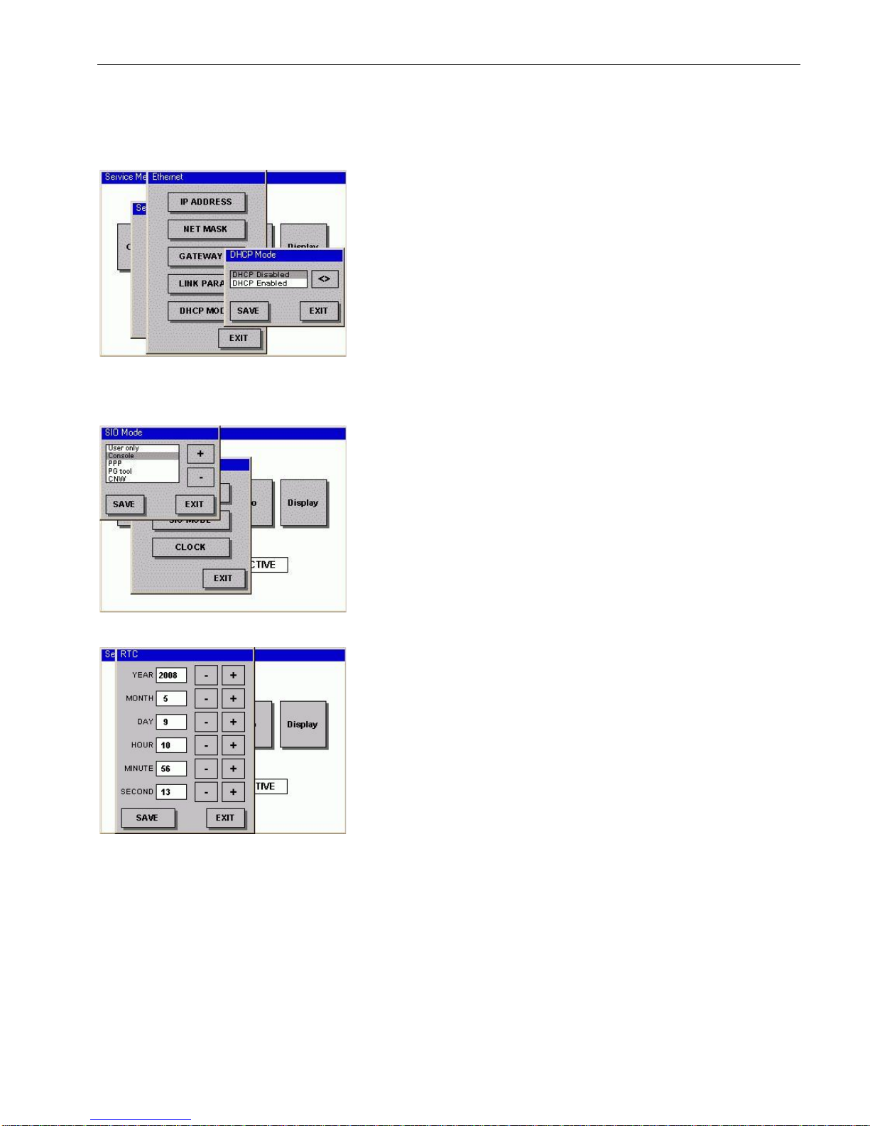
USER MANUAL 1.10 | DC1000 DIALOG-CONTROLLER
Berghof Automation GmbH | Harretstrasse 1 | 72800 Eningen | www.berghof.com
2VF100108FE04.docx | DC1000_HB_en_2D0982010ZD00.docx
63
DHCP Mode:
Disabled: The IP ADDRESS set on the Dialog-Controller
is valid.
Enabled: The IP ADDRESS is automatically retrieved
from a DCHP server.
Caution: If DHCP is enabled, and there is no DHCP
server available, the Controller will not boot! The Controller waits for a DHCP to allocate a valid IP address to it.
If no DHCP server is present, the Dialog-Controller can
only boot if the DHCP disabled setting has been configured. For this purpose the device must be put into configuration mode and can be converted via COM1 (X4) by
means of web configuration (see manual: CP1131-P introduction).
Setting the COM1(X4) serial interface.
User only: COM1 is available for CODESYS application
Console: Debug outputs of the operating system
PPP: TCP/IP over PPP protocol
PG Tool: CODESYS can upload and debug serial pro-
grams
CNW: reserved
RTC: Setting the battery-buffered realtime clock.
Ethernet
“DHCP Mode”
SIO MODE
“SIO MODE”
CLOCK “RTC”
Page 64
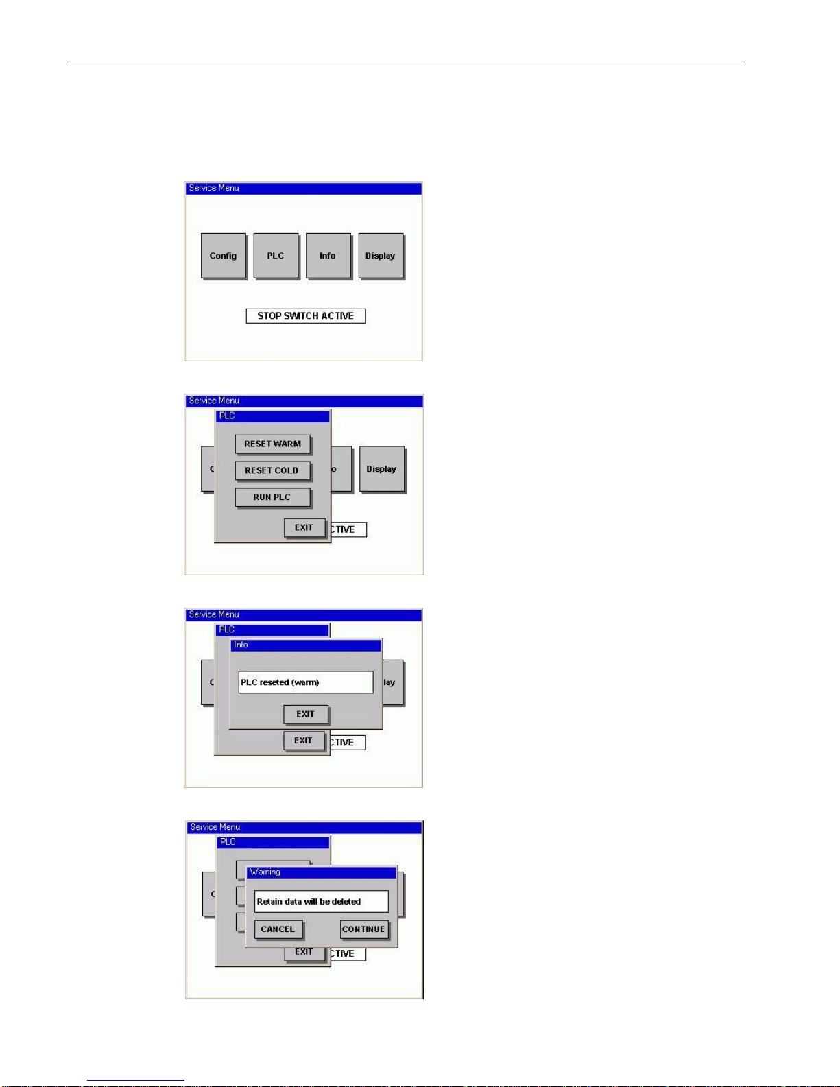
USER MANUAL 1.10 | DC1000 DIALOG-CONTROLLER
Berghof Automation GmbH | Harretstrasse 1 | 72800 Eningen | www.berghof.com
DC1000_HB_en_2D0982010ZD00.docx | 2VF100108FE04.docx
64
“PLC” service menu
Change the PLC state.
RESET WARM: After an error occurs the PLC program
can be reset. With the exception of the RETAIN variables,
all variables can be reset.
RESET COLD: After an error occurs the PLC program
can be reset. With the exception of the RETAIN variables,
all of the variables are reset, including the RETAIN variables.
RUN PLC: Starting the PLC program.
NOTE: RETAIN data are remanent data. They are saved
when the Controller is switched off and are available to it
when it is rebooted. If these data are deleted, important
system data of the application may be deleted!
Info:
Acknowledgement of the RESET WARM command.
PLC program and all variables, with the exception of the
RETAIN variables, have been reset.
Warning:
Acknowledgement of the RESET COLD command.
As soon as the “CONTINUE” button is pressed the PLC
program and all variables, including the RETAIN variables, are reset.
PLC
PLC
PLC
“RESET WARM”
PLC
“RESET COLD”
Page 65
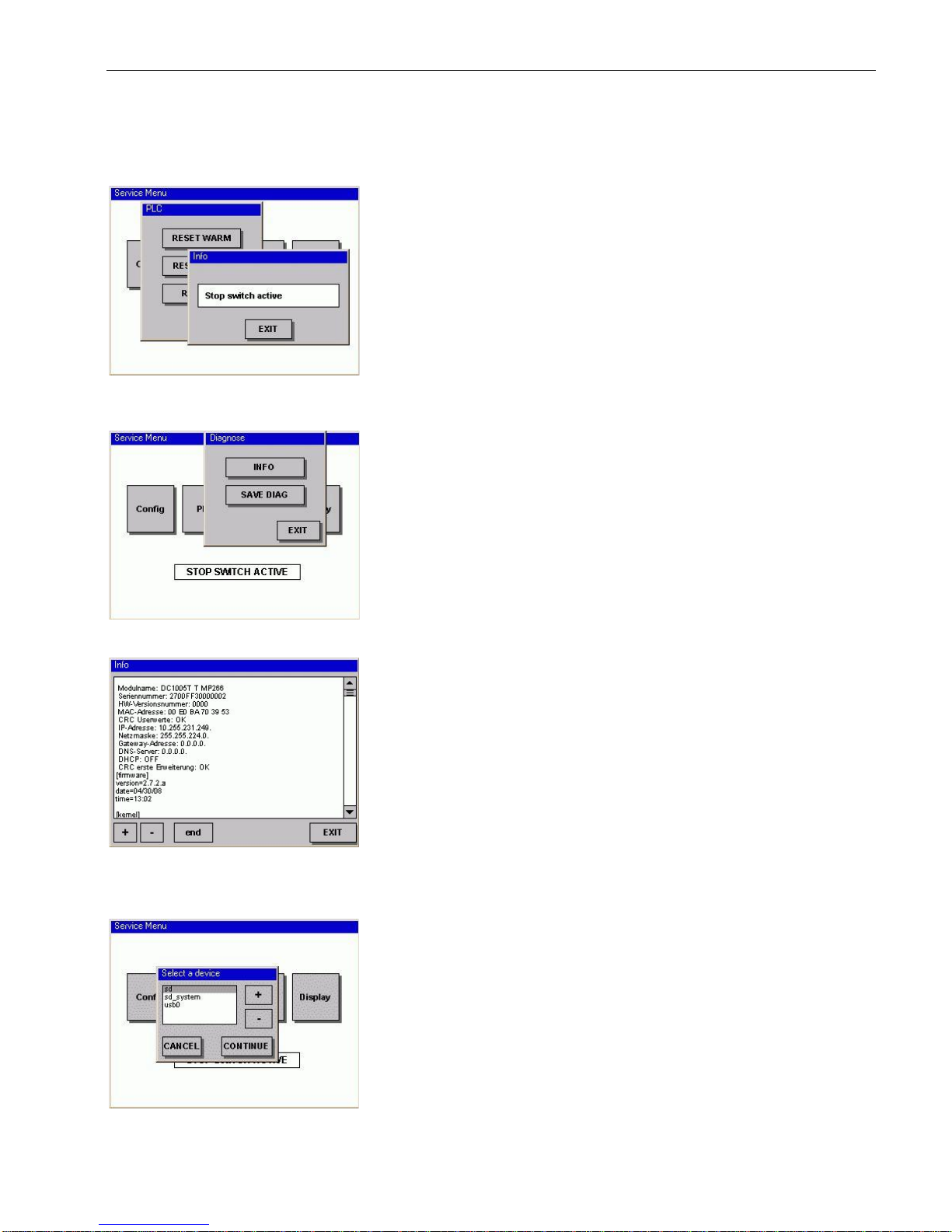
USER MANUAL 1.10 | DC1000 DIALOG-CONTROLLER
Berghof Automation GmbH | Harretstrasse 1 | 72800 Eningen | www.berghof.com
2VF100108FE04.docx | DC1000_HB_en_2D0982010ZD00.docx
65
Info:
If there is a PLC program on the Dialog-Controller and it
was possible to start it successfully, the Service Menu is terminated and PLC program executed. If the PLC program is
not executed, the following may be the causes:
There is no PLC program on the Dialog-Controller.
Mode selector switch is set at “STOP”.
An error in the PLC program was not acknowledged
by a “RESET” command (see above).
“INFO” service menu
Diagnostics:
INFO: Diagnostic data displayed
SAVE DIAG: Diagnostic data is saved on USB stick or SD
card.
Info:
Diagnostic data displayed:
Parameter display
Hardware and software versions
Event logger
Displays all user activities as well as messages and software
module problems.
To aid in diagnostics, the entire content of the displayed
page can be uploaded to a PC using the integrated “Web
Configuration” where it can then be saved and sent to
Berghof. The individual event logger messages as well as the
web configuration are explained in the “CANtrol PPC System Introduction” manual.
Select a device:
The currently available storage media are displayed here. If
neither a USB stick nor an SD card is available, the selection
is empty.
sd: Data partition of the SD card
sd_system: System partition of an SD card is used, for ex-
ample, for the PLC program
usb0: the first USB to be plugged in (a maximum of 8 sticks
can be plugged in via a USB hub).
PLC “RUN PLC”
“Info”
Info
Info “SAVE DIAG”
Page 66
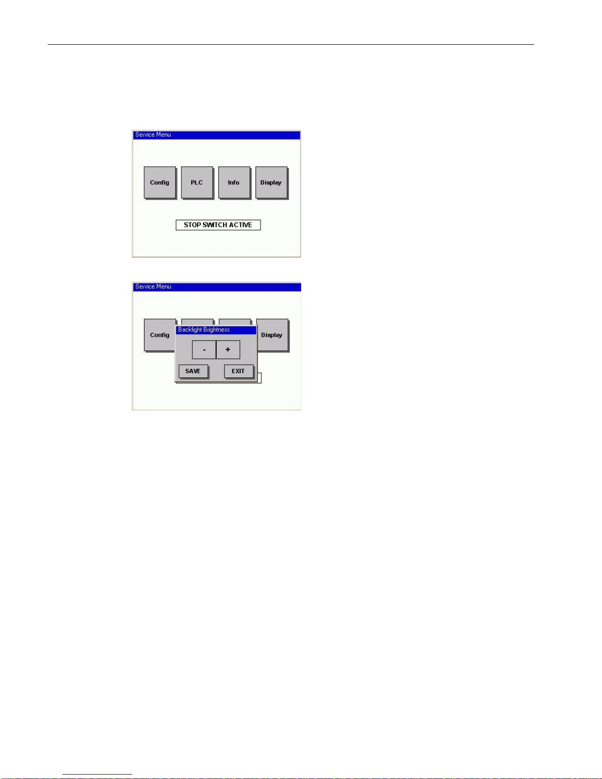
USER MANUAL 1.10 | DC1000 DIALOG-CONTROLLER
Berghof Automation GmbH | Harretstrasse 1 | 72800 Eningen | www.berghof.com
DC1000_HB_en_2D0982010ZD00.docx | 2VF100108FE04.docx
66
“Display” service menu
Status display or contrast and backlighting adjustment.
Dialog-Controllers with TFT displays:
The brilliance of the backlighting can be set by means of
the “+/-” keys. Changes are applied immediately and will
remain in effect until the next restart, even if you leave the
menu with the “EXIT” button. The new value is saved by
means of the “Save” button. The “EXIT” button allows
you to leave the menu without saving any changes which
may have been made (although such changes will remain
in effect until the next restart).
Dialog-Controllers with monochrome displays:
The contrast can be adjusted here.
Display
Display
“Brightness”
Page 67
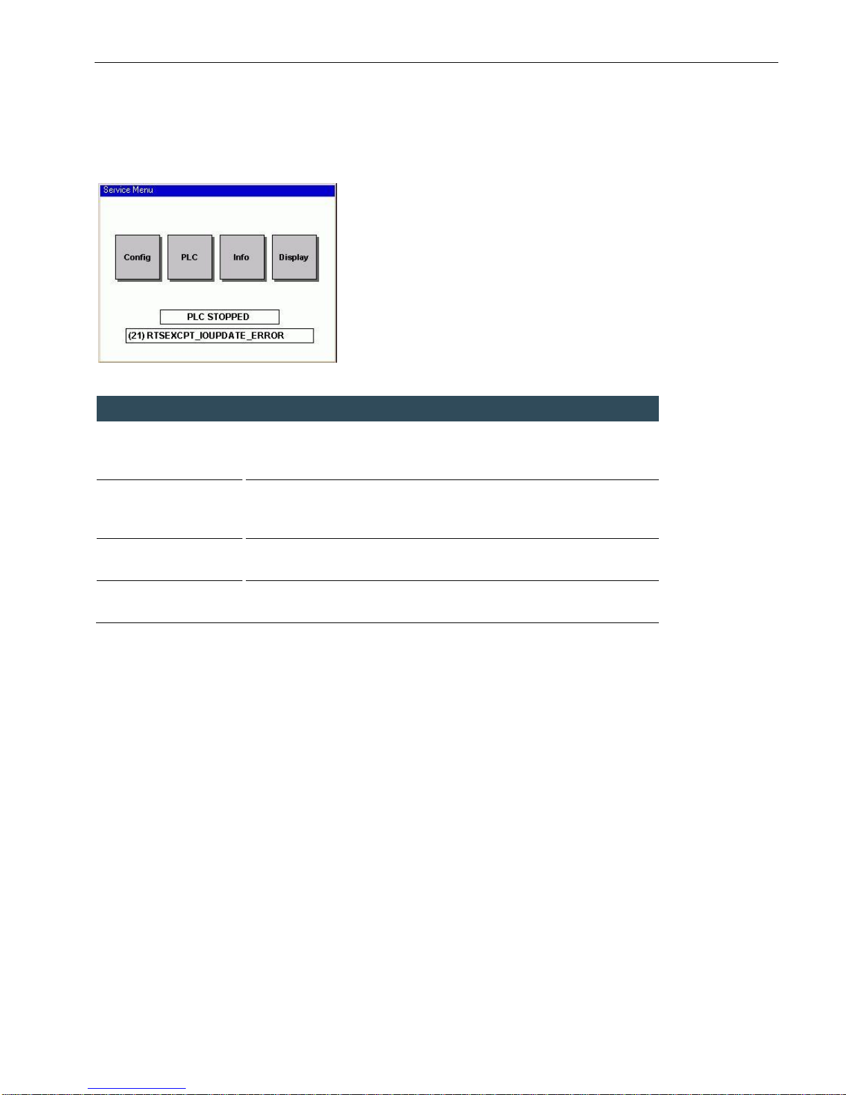
USER MANUAL 1.10 | DC1000 DIALOG-CONTROLLER
Berghof Automation GmbH | Harretstrasse 1 | 72800 Eningen | www.berghof.com
2VF100108FE04.docx | DC1000_HB_en_2D0982010ZD00.docx
67
3.3.3. PLC window
The following states of the PLC Controller can be represented in line 1 of the PLC window:
STOP SWITCH ACTIVE
PLC STOPPED
PLC NO PROGRAM
PLC ERROR STOP
Display
Description
STOP SWITCH ACTIVE
Operating mode selection switch S1 is set to the STOP position. The PLC
program can only be started with a programming tool if S1 is set in the RUN
position.
PLC STOPPED
Operating mode selection switch S1 is set to the RUN position. However the
PLC program has been put into the STOP state or there is another upcoming error, which has not yet been acknowledged with RESET.
PLC NO PROGRAM
Operating mode selection switch S1 is set to the RUN position, but no PLC
program is loaded.
PLC ERROR STOP
Operating mode selection switch S1 is set to the RUN position. However, the
PLC program could not be started due to an error.
STOP
in the Service menu
Page 68
USER MANUAL 1.10 | DC1000 DIALOG-CONTROLLER
Berghof Automation GmbH | Harretstrasse 1 | 72800 Eningen | www.berghof.com
DC1000_HB_en_2D0982010ZD00.docx | 2VF100108FE04.docx
68
If an error occurs when the PLC program is started, the following states may be displayed on line 2 in the
PLC window:
Display
Description
BOOTPROJECT_REJECTED_RETAIN_ERROR
The Dialog-Controller has detected a difference between the PLC program saved as the boot project
and the most recently loaded PLC program. The
latter was only loaded to RAM and was not saved
as a boot project. If the Dialog-Controller is
switched off in this situation; the system notes the
ID number of the program previously loaded to
RAM. The displayed message now prevents the
automatic startup of a possibly outdated PLC program.
Error correction:
Either load, save and then start the new PLC program or use a reset command to start the saved
and possibly outdated program.
RETAIN_IDENTITY_MISMATCH
The Dialog-Controller was unable to correctly
reestablish the retain variables.
Error correction:
By performing a reset, the saved PLC program can
be started using the reset retain variables.
RTSEXCPT_IOUPDATE_ERROR
One or all of the E-bus modules were not detected
after the PLC program started. The E-bus modules
also include the I/O expansion cards installed in the
Dialog-Controller. All E-bus modules entered in the
controller configuration must be present and must
be supplied with power at the time the program
starts.
Error correction:
Check the number and type of E-bus modules entered in the controller configuration. Check the contacts and wiring connections on these E-bus modules. Once the number of actually available E-bus
modules agrees with the controller configuration
setting, the controller can be restarted using a reset
command.
Page 69
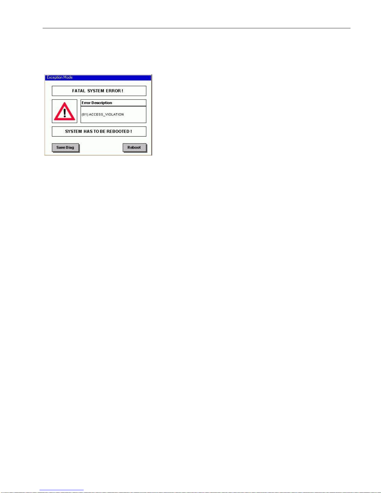
USER MANUAL 1.10 | DC1000 DIALOG-CONTROLLER
Berghof Automation GmbH | Harretstrasse 1 | 72800 Eningen | www.berghof.com
2VF100108FE04.docx | DC1000_HB_en_2D0982010ZD00.docx
69
This display appears if an error has occurred when the
PLC program is executed, i.e. during program run.
The following error statuses can be displayed:
ACCESS_VIOLATION
RTSEXCPT_WATCHDOG
RTSEXCPT_DIVIDEBYZERO
Standard procedure in case of an error:
Saving all relevant data is an important factor for error
analysis. The diagnostic information generated by the device should be saved for this reason.
“Save Diag” is used to store the relevant diagnostic data
for example on a plugged-in USB stick. After such an error
the Controller must be rebooted. This takes place after
data backup, using the “Reboot” button.
Note:
The diagnostic data must definitely be saved prior to rebooting because only at this time can all the important
data be saved!
EXCEPTION
Major exceptional
errors
Page 70
USER MANUAL 1.10 | DC1000 DIALOG-CONTROLLER
Berghof Automation GmbH | Harretstrasse 1 | 72800 Eningen | www.berghof.com
DC1000_HB_en_2D0982010ZD00.docx | 2VF100108FE04.docx
70
Display
Description
ACCESS_VIOLATION
Illegal memory access by the PLC program, e.g. by an invalid pointer.
Error correction:
The program error can be identified from the diagnostic data and/or the
Breakpoint List file (BPL) generated by CODESYS, and eliminated.
Further information on debugging with the aid of BPL files and debug-
ging in general is to be found in the “CODESYS Online Help” in the
“Berghof Target” section.
RTSEXCPT_WATCHDOG
It was not possible for a task within the PLC program, which is monitored by a watchdog to become active during the monitoring time. This
important watchdog-monitoring makes it possible to find errors in the
execution behaviour and in the tasking of the PLC program. For such
errors to be found at all it is important that each task is monitored by a
watchdog.
Error correction:
The program error can be identified from the diagnostic data and/or the
Breakpoint List file (BPL) generated by CODESYS, and eliminated.
Further information on debugging with the aid of BPL files and debug-
ging in general is to be found in the “CODESYS Online Help” in the
“Berghof Target” section.
RTSEXCPT_DIVIDEBYZERO
Division by zero in the PLC program prompts an error stop.
Error correction:
The program error can be identified from the diagnostic data and/or the
Breakpoint List file (BPL) generated by CODESYS, and eliminated.
Further information on debugging with the aid of BPL files and debug-
ging in general is to be found in the “CODESYS Online Help” in the
“Berghof Target” section.
3.4. Decommissioning
3.4.1. Disposal
Disassembly
The Dialog-Controller must be disassembled into its component parts for disposal. All metal components can
be disposed of as recyclable metal.
Electronic waste
All electronic components such as PCBs, drives, etc. must be set aside and disposed of separately. Disposal is
generally regulated by national and local ordinances which must be complied with.
Page 71
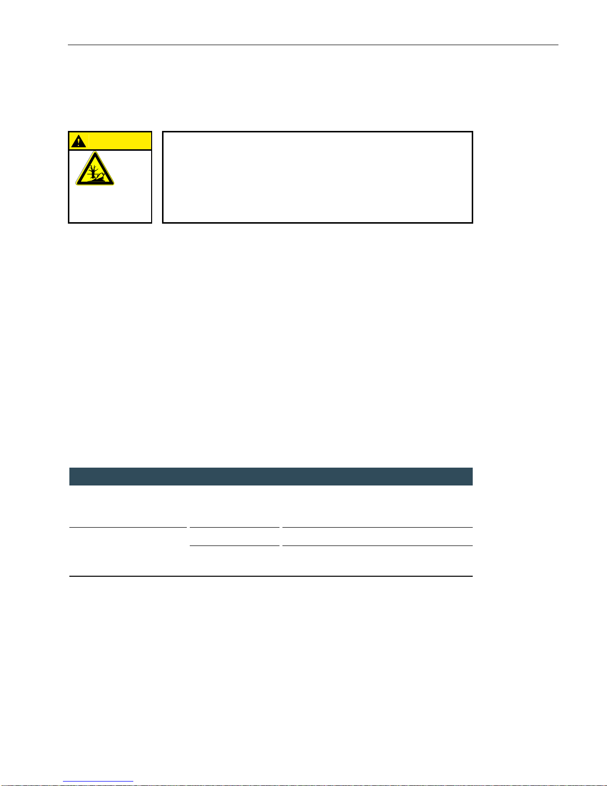
USER MANUAL 1.10 | DC1000 DIALOG-CONTROLLER
Berghof Automation GmbH | Harretstrasse 1 | 72800 Eningen | www.berghof.com
2VF100108FE04.docx | DC1000_HB_en_2D0982010ZD00.docx
71
Battery
CAUTION
Batteries contain materials which represent health and environmental
hazards.
Batteries may only be disposed of at an authorized waste disposal facility.
Make sure the battery is fully discharged before disposing of it. If necessary,
place an insulating strip across the contacts to prevent short circuits.
HAZARDOUS
MATERIAL
EMISSIONS
3.5. Maintenance
Cleaning
In order to prevent accidental activation and possible problems, the Dialog-Controller must be switched off
when the front panel is cleaned. Use a clean, moistened, lint-free cloth to clean the front of the Dialog-Controller.
Please note the following to avoid damaging the front panel when cleaning it:
Never use high-pressure or steam washers.
Never use caustic cleaning agents (even diluted), abrasives or hard objects to clean the panel.
Do not apply excessive pressure to the front panel when cleaning it.
3.6. Help in case of problems
Please read the section “Basic safety measures”. If the measures described there do not solve the problem,
please contact your supplier’s Service Department.
Fault
Possible cause
Recommended action
No function after the DialogController is started.
No power supply to
the Dialog-Controller.
Make sure the power cord is plugged in.
Check the pin assignment for reversed polarity.
Check (measure) the connecting voltage.
The Dialog-Controller fails to
completely boot.
Memory fault.
Return the device for service.
Corrupted software.
Put the device in the configuration mode and
reload the firmware.
Page 72

USER MANUAL 1.10 | DC1000 DIALOG-CONTROLLER
Berghof Automation GmbH | Harretstrasse 1 | 72800 Eningen | www.berghof.com
DC1000_HB_en_2D0982010ZD00.docx | 2VF100108FE04.docx
72
Blank page
Page 73
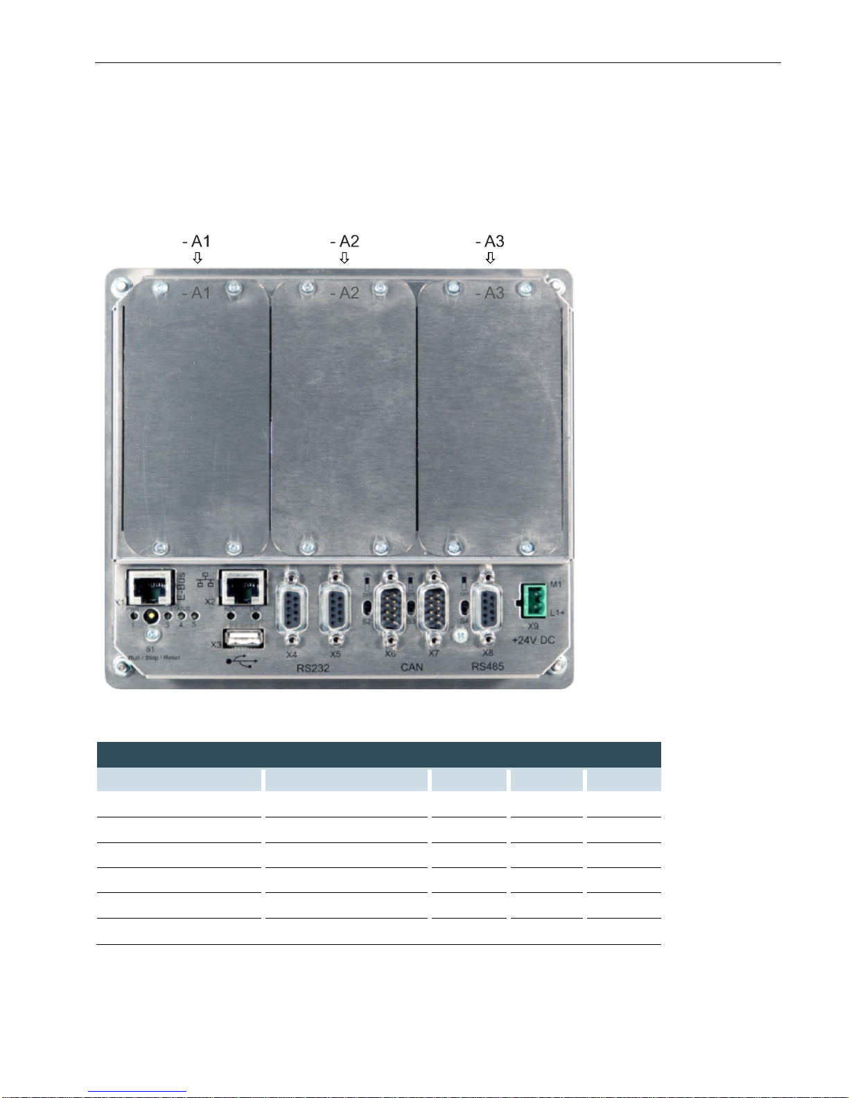
USER MANUAL 1.10 | DC1000 DIALOG-CONTROLLER
Berghof Automation GmbH | Harretstrasse 1 | 72800 Eningen | www.berghof.com
2VF100124FE08.docx | DC1000_HB_en_2D0982010ZD00.docx
73
4. Extension modules
2VF100304DG01.cdr
Extension modules
Slot
Type
Designation
A1
A2
A3
I/O card with SC-CAN
U DC XS 12/8/4-CSC
X
PROFIBUS master
DC Profibus-DPM
X
PROFIBUS slave
DC Profibus-DPS
X
PROFIBUS master/slave
DC Profibus-DPV
X
I/O card, analog/digital
DCXR01
X X X
I/O card, digital
DCXR02
X X X
Slot marking for extension modules
Page 74
USER MANUAL 1.10 | DC1000 DIALOG-CONTROLLER
Berghof Automation GmbH | Harretstrasse 1 | 72800 Eningen | www.berghof.com
DC1000_HB_en_2D0982010ZD00.docx | 2VF100124FE08.docx
74
4.1. I/O card with SC-CAN interface
The I/O card is an I/O module which is permanently installed in a DialogController.
2VF100305DG00.cdr
Performance features - an overview
12 digital inputs
8 digital outputs
4 digital inputs/outputs
2 digital inputs can also be used as counters
2 analog inputs, 0 ... 10 V or 0 ... 20 mA
1 CAN interface for contact line systems with monitoring capability
Connection for a 5-place 7-segment display with remote control receiver
The scope of supply of the control module consists of:
I/O card installed in the Dialog-Controller
Short description
Scope of supply
IN 1-8
SC-CA
N
1
M
1
I/O 13-16
9
7Seg/IR
SC-Test
IN 9-12
2 3
1
2
X10
X13
X9
X1
X6
X4
X1
X2
X5
X7
OUT 1-8
X3
X8
X11
M
1
M
1
M
1
L1+
1 2
3
1 2 3
1 2 3 4 5 6 7 8 1 2 3 4 5 6 7 8
9
1 2 3 4 5 6 7 891 2 3 4 5 6 7 8
L1+
9
1
2 345 6 7 891 2 345 6 7 8
M
1
1
2 345 6 7 8
1 2 3 4 5 6 7 8
2
1
2 3 4 5 6
9
9
9
GNDGNDS
C
AIN 1GNDShiel
d
AIN 2GNDShiel
d
CANGN
D
- A2
Page 75
USER MANUAL 1.10 | DC1000 DIALOG-CONTROLLER
Berghof Automation GmbH | Harretstrasse 1 | 72800 Eningen | www.berghof.com
2VF100124FE08.docx | DC1000_HB_en_2D0982010ZD00.docx
75
4.1.1. Technical data
Module data
Versions / part no.
Only available as a built-in module
Dimensions, WxH[mm]
113.5 x 10⁸
Weight
Approx. 100 g
Operating temperature
range
5 °C to 55 °C (condensation free) Convection cooling ensured
EMI, protection class, insulation test, protection type (installed)
Interference emission
EN 61000-6-4, industrial application
Interference resistance
EN 61000-6-2, industrial application
Protection class
III
Insulation resistance
EN 61131-2; DC 500 V test voltage
Protection type
IP 20
Supply voltage, current consumption
Module electronics power
supply
(connection voltage)
SELV DC +24 V < 0.4 A (EN 61131-2)
Digital I/O power supply
DC +24 V (EN 61131-2) together with module supply
Current consumption
At Ue= DC +24 V in neutral, max. 500 mA,
fusing based on I/O load, max. 8 A
Protection against supply
voltage pole reversal
Yes
Potential isolation
No
Digitale inputs/outputs (DIO)
Number of inputs
12 (X1/X2), of which 4 can be used as +24 V encoder inputs;
counter frequency at 4x evaluation < 20 kHz
Number of outputs
8 (X9)
Number of inputs/outputs
4 (X2)
Output current
0.5 A
Short circuit protection
Yes
Potential isolation
Yes
Connection technique
Standing front wiring for 3.81 terminal strips (not part of the standard delivery)
Page 76
USER MANUAL 1.10 | DC1000 DIALOG-CONTROLLER
Berghof Automation GmbH | Harretstrasse 1 | 72800 Eningen | www.berghof.com
DC1000_HB_en_2D0982010ZD00.docx | 2VF100124FE08.docx
76
Analog inputs
Number
2 analog inputs, 0 … 20 mA / 0 ... 10 V switchable (X10/X13)
Input characteristics
Up to 20 mA U < 5 V in case of short circuit, max. 40 mA
Resolution
10 bit (accuracy 8 bit)
Connection technique
Standing front wiring for 3.81 terminal strips (not part of the standard delivery)
CAN interfaces
Number and type of interfaces
1 CAN interface for (X20) contact line communications / SC_CAN (X3);
1 SC_CAN monitoring interface with standard signals
Connection technique
Standing front wiring for 3.81 terminal strips (not part of the standard delivery)
Operating and display elements
Display elements
Interface (X11) for 5-place, 7-segment display with IR receiver diode for
remote control
Page 77
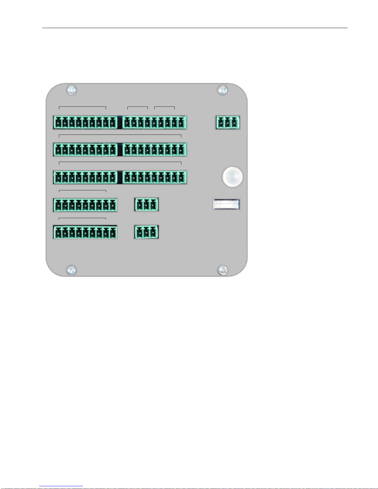
USER MANUAL 1.10 | DC1000 DIALOG-CONTROLLER
Berghof Automation GmbH | Harretstrasse 1 | 72800 Eningen | www.berghof.com
2VF100124FE08.docx | DC1000_HB_en_2D0982010ZD00.docx
77
4.1.2. Pin assignment
2VF100305DG00.cdr
I/O supply
The digital and analog I/Os must be supplied from an external source. An input voltage of 24 VDC (-15 % /
+20 %) is permissible. The I/Os are equipped with a built-in pole reversal protection.
The power cord and the external power supply must be equipped with an external short circuit and overload
protection with an activation current of max. 8 A (depending on the number of I/Os).
External power supply
The CAN communications interface is supplied from the Dialog-Controller’s power supply.
Pin overview
Power supply
IN 1-8
SC-CA
N
1
M
1
I/O 13-16
9
7Seg/IR
SC-Test
IN 9-12
2 3
1
2
X10
X13
X9
X1
X6
X4
X1
X2
X5
X7
OUT 1-8
X3
X8
X11
M
1
M
1
M
1
L1+
1 2
3
1 2 3
1 2 3 4 5 6 7 8 1 2 3 4 5 6 7 8
9
1 2 3 4 5 6 7 8
9
1 2 3 4 5 6 7 8
L1+
9
1
2 345 6 7 8
9
1 2 345 6 7 8
M
1
1
2 345 6 7 8
1 2 3 4 5 6 7 8
2
1
2 3 4 5 6
9
9
9
GND
GND
S
C
AIN 1GNDShiel
d
AIN 2GNDShiel
d
CANGN
D
- A2
Page 78
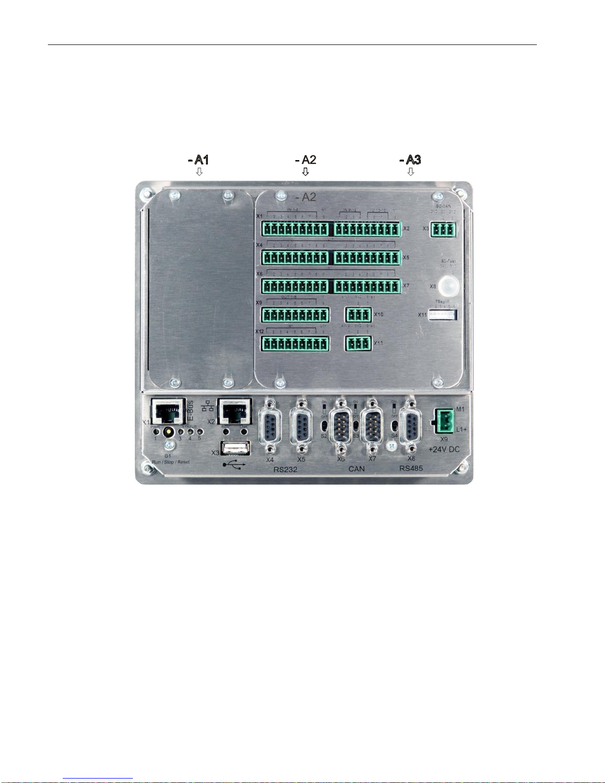
USER MANUAL 1.10 | DC1000 DIALOG-CONTROLLER
Berghof Automation GmbH | Harretstrasse 1 | 72800 Eningen | www.berghof.com
DC1000_HB_en_2D0982010ZD00.docx | 2VF100124FE08.docx
78
The I/O card is factory installed and may only be installed in the Dialog-Controller in the position shown in
the figure below.
2VF100306DG00.cdr
Installation
Page 79
USER MANUAL 1.10 | DC1000 DIALOG-CONTROLLER
Berghof Automation GmbH | Harretstrasse 1 | 72800 Eningen | www.berghof.com
2VF100124FE08.docx | DC1000_HB_en_2D0982010ZD00.docx
79
WARNING
The transmission circuit voltage level of the SC_CAN signals is 85 V or
110 V at 25 Ohm.
Based on the employed voltage level, all signal carrying lines must exhibit the
same level of contact protection as the power supply (230 / 400 V).
CAUTION
Directly connecting ISO11898 devices to the SC_CAN bus will result in
there being destroyed and is therefore prohibited.
Such devices include, for example, remote I/Os, drive controllers and CAN bus
analyzers.
SC_CAN – X3 pin assignment
Pin
Signal
Description
1
PE
Protective earth
2
SC
SC_CAN signal
3
PE
Protective earth
CAUTION
The two protective earth (PE) connectors must be laid to the contact line
connection using two separate conductors.
Any other type of circuit construction (e.g., a bridge between the two PE connections) may result in functional errors or functional inefficiency of the
SC_CAN.
Termination
The SC_CAN must be terminated at both line ends. The values for these terminating resistors deviate from
the ISO 11898 (CAN bus) standard and they can be ordered separately from Berghof (CTR-SC-T2, part no.:
201601200).
CAUTION
If the SC_CAN bus is incorrectly terminated, its operation can result in
the destruction of the I/O subassembly!
You must ensure that the correct termination is employed!
Baud rate
The preset baud rate for the SC_CAN is 50 kbit/s. The SJA1000 CAN controller is also in the “self test mode”,
that is, when a CAN telegram is correctly transmitted, it is not necessary for a subscriber to send a CAN ACK
signal. Should it become necessary, these factory settings can be altered in the application by using the
appropriate CAN library.
CAN bus for contact
line communications
Page 80
USER MANUAL 1.10 | DC1000 DIALOG-CONTROLLER
Berghof Automation GmbH | Harretstrasse 1 | 72800 Eningen | www.berghof.com
DC1000_HB_en_2D0982010ZD00.docx | 2VF100124FE08.docx
80
SC test - X8 pin assignment
Pin
Signal
Description
1
CAN
CAN signal
2
GND
Signal ground
A test or so-called “monitoring interface” for the SC_CAN is located on this connector. This “monitoring in-
terface” serves to analyze the SC_CAN telegrams and possess the following characteristics:
It is a point-to-point interface;
It is only for devices with an ISO11898 CAN interface;
CAN telegrams cannot be sent;
No terminating resistors may be employed.
Pin assignment for an adapter cable
2-pin post (2.54)
9-pin Sub D
Pin
Signal
Signal
Pin
1
CAN
CAN HIGH
2 2 GND
CAN LOW
7
For special applications an external 7-segment display (with integrated infrared receiver) can be connected to
the I/O subassembly. Connection is to connector X11 by means of a cable available from Berghof. The external display can be addressed from the software in the same way as the digital I/Os.
2-pin post connector
External 7-segment
display
Page 81
USER MANUAL 1.10 | DC1000 DIALOG-CONTROLLER
Berghof Automation GmbH | Harretstrasse 1 | 72800 Eningen | www.berghof.com
2VF100124FE08.docx | DC1000_HB_en_2D0982010ZD00.docx
81
4.1.3. Analog inputs
The module is equipped with two unipolar analog inputs protected by diodes. Power supply to the sensors is
from an external source. The analog current and voltage values are accessible via the CODESYS controller
configuration.
Input channel data
Current measurement
Nominal input current value
0 … 20 mA
Maximum input current value
40 mA (Ue = +24 V)
Voltage measurement
Nominal input voltage value
0 … 10 V
Maximum input voltage value
12 V
General data
Input filter, 1st order
= 1 ms for current; = 10 ms for voltage measurement
Conversion method
Successive approximation, no error codes
Resolution
10 bit; 1 LSB = 19.5 µA / 9.77 mV
Accuracy within the 0...50 °C
temperature range
±1 %
Pole reversal protection
Yes
Sampling rate
Approx. 1 ms
NOTICE
Due to internal protective circuitry, the load is nonlinear for current operation.
Analog IN – X10/13 pin assignment
Pin
Signal
Description
1
AIN
Analog input
2
GND
Signal ground
3
Shield
Shield
The maximum value will be indicated if no sensor is connected to an analog input.
NOTICE
Shield support in switchgear cabinet is urgently recommended for reasons of EMC!
Page 82
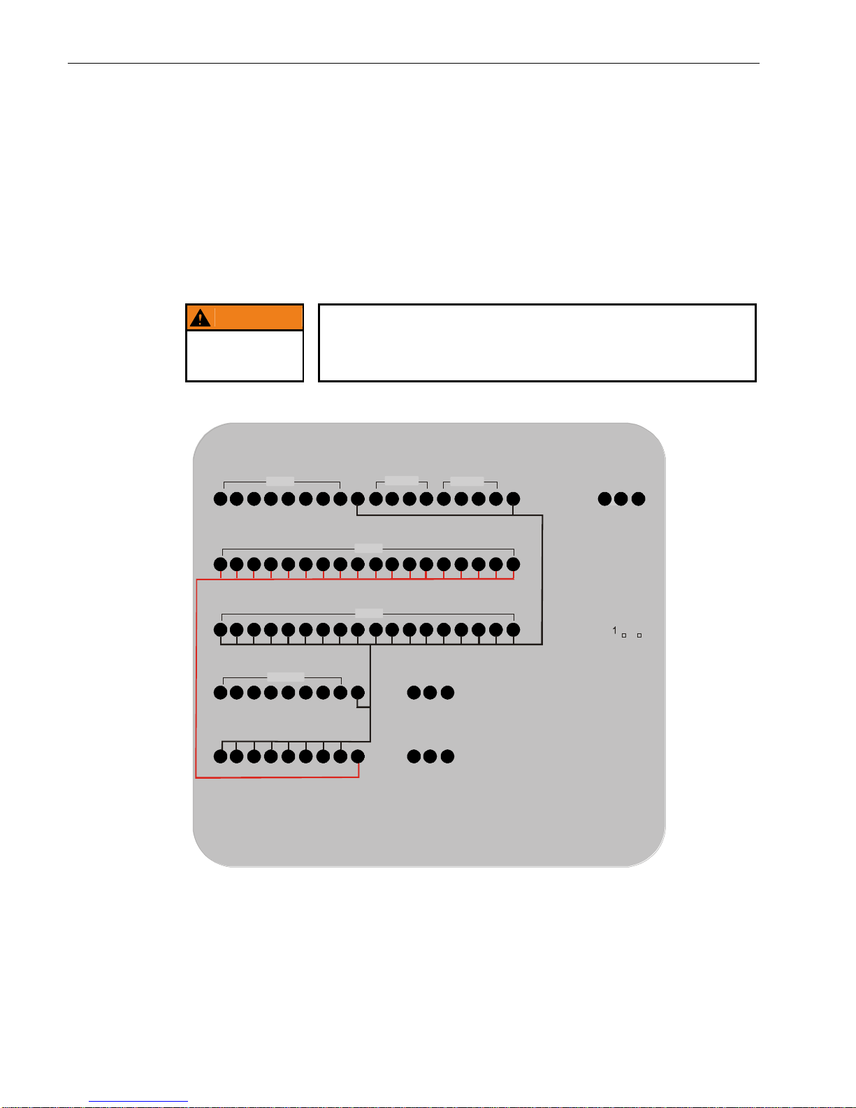
USER MANUAL 1.10 | DC1000 DIALOG-CONTROLLER
Berghof Automation GmbH | Harretstrasse 1 | 72800 Eningen | www.berghof.com
DC1000_HB_en_2D0982010ZD00.docx | 2VF100124FE08.docx
82
4.1.4. Digital inputs/outputs 12/4/8-0.5
Supply is to terminals L1+ and M1. All inputs and outputs have a common feed and therefore also have a
common feed potential.
Feed
The feed must come directly (unswitched) from the feed device. Feed for inputs (sensors) must come directly
from the feed device. Do not lay the sensor supply across switched circuits.
WARNING
Feedback can result in the destruction of the module and/or the sensors!
With the group power supply switched off, the connected sensors may produce
feedback via the output transistors. Make sure that the sensors are all supplied
from the same power source as the module’s associated I/O group.
2VF100307DG00.cdr
1 2 3 4 5 6 7 8 9 1 2 3 4 5 6 7 8 9
1 2 3 4
5
6 7 8 9 1 2 3 4
5
6 7 8 9
1 2 3 4 5 6 7 8 9
1 2 3 4 5 6 7 8 9
1 2 3
1
1 2 3
1
1 2 3
1
X9
X12
X6
X4
X1
X10
X13
X2
X5
X7
IN 1-8
SC-
C
A
N
M1 I/O 13-16IN 9-12
M
1
GND
GND
S
C
M
1
L1+
L1+
M1
AIN
1GNDShield
AIN 2GNDShiel
d
7Seg/IR
SC-Test
1 2
X8
1
2 3 4 5 6
CANGN
D
X11
OUT 1-8
M
1
X3
- A2
1 2 3 4
5
6 7 8 9 1 2 3 4
5
6 7 8 9
Page 83
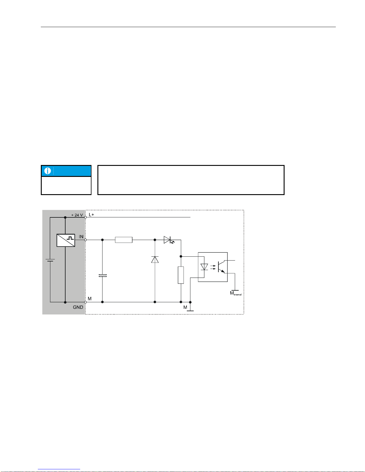
USER MANUAL 1.10 | DC1000 DIALOG-CONTROLLER
Berghof Automation GmbH | Harretstrasse 1 | 72800 Eningen | www.berghof.com
2VF100124FE08.docx | DC1000_HB_en_2D0982010ZD00.docx
83
4.1.5. Digital inputs, positive switched
The digital inputs are positive-switching, type 1 inputs for 3-wire sensors. They are designed for nominal
24 V input voltages. The inputs are transmitted to the CPU in cycles. An open input is interpreted as being
static 0 (LOW).
Impulse detection and interference suppression
Inputs are read in cycles. Impulses of < 100 µs are suppressed by the hardware. The shortest possible sampling rate is 250 µs. In order for impulses to be properly detected they must be longer than the sampling rate
defined by the software.
Multiple sampling can be programmed to suppress interference impulses. The sampling rate and multiple
sampling (filtering) can be activated in individual groups of 32 inputs.
NOTICE
This function is only available for C applications. The sampling rate is predefined under IEC 61131-3.
2VF100009DG01.cdr
Basic input circuit
diagram
Page 84
USER MANUAL 1.10 | DC1000 DIALOG-CONTROLLER
Berghof Automation GmbH | Harretstrasse 1 | 72800 Eningen | www.berghof.com
DC1000_HB_en_2D0982010ZD00.docx | 2VF100124FE08.docx
84
Digital input data
Module data
Number of inputs
12 (max. 16 if the I/O is used as an input)
Line length
in the circuit cabinet
Take the voltage drop into account when selecting a conductor. Other than this, there are no relevant restrictions.
field wiring
Comply with all locally applicable requirements as well as
those in accordance with EN 61131-3. Where the risk of
lightning exists, please consult the manufacturer.
Nominal load voltage, L+
Pole reversal protection
DC 24 V (SELV)
Yes
Potential isolation
Yes (optocoupler) in groups
Status indicator
None
Alarms
Definable depending on the software
Input delay
Definable via the software
Input capacitance
< 10 nF
Page 85
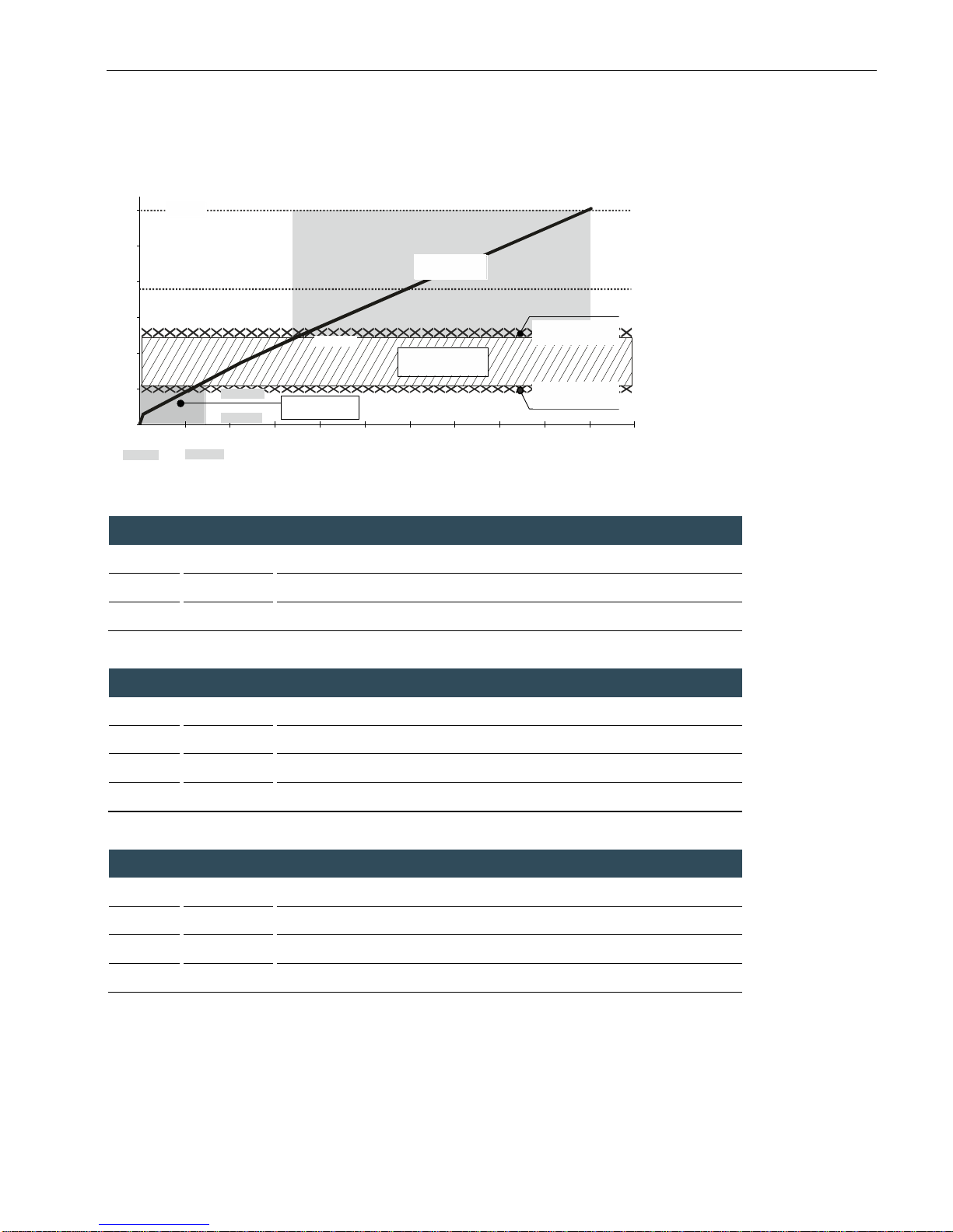
USER MANUAL 1.10 | DC1000 DIALOG-CONTROLLER
Berghof Automation GmbH | Harretstrasse 1 | 72800 Eningen | www.berghof.com
2VF100124FE08.docx | DC1000_HB_en_2D0982010ZD00.docx
85
2VF100010DG01.cdr
Input voltage (DC) of extern power supply
Ue
24 V
Rated voltage
Ue max.
30 V
Upper limit
Ue min.
19.2 V
Lower limit
Limits for “1” signal for the “ON” condition
UH
max.
30.0 V
Upper voltage limit
IH
max.
10.0 mA
Upper current limit
UH
min.
13.5 V
Lower voltage limit
IH
min.
3.5 mA
Lower current limit
Limits for “0” signal for the “OFF” condition
UL
max.
5.5 V
Upper voltage limit
IL
max.
1.5 mA
Upper current limit
UL
min.
0 V
Lower voltage limit
IL
min.
0 mA
Lower current limit
U max.
e
UH max.
IH max. IH min.
U = 24 V DC
e
U min.
e
5,0
10,0
15,0
20,0
25,0
30,0
U [V]
0,0
0,00 1,00 2,00 3,00 4,00 5,00 6,00 7,00 8,00 9,00 10,00 11,00
[mA] I
UH min.
UL min.
UL max.
IL max.
IL min.
'ON' / HIGH - area
cross-over area
noise margin < 1 V
noise margin < 1 V
'OFF' / LOW - area
Operating ranges
of the digital inputs
Page 86
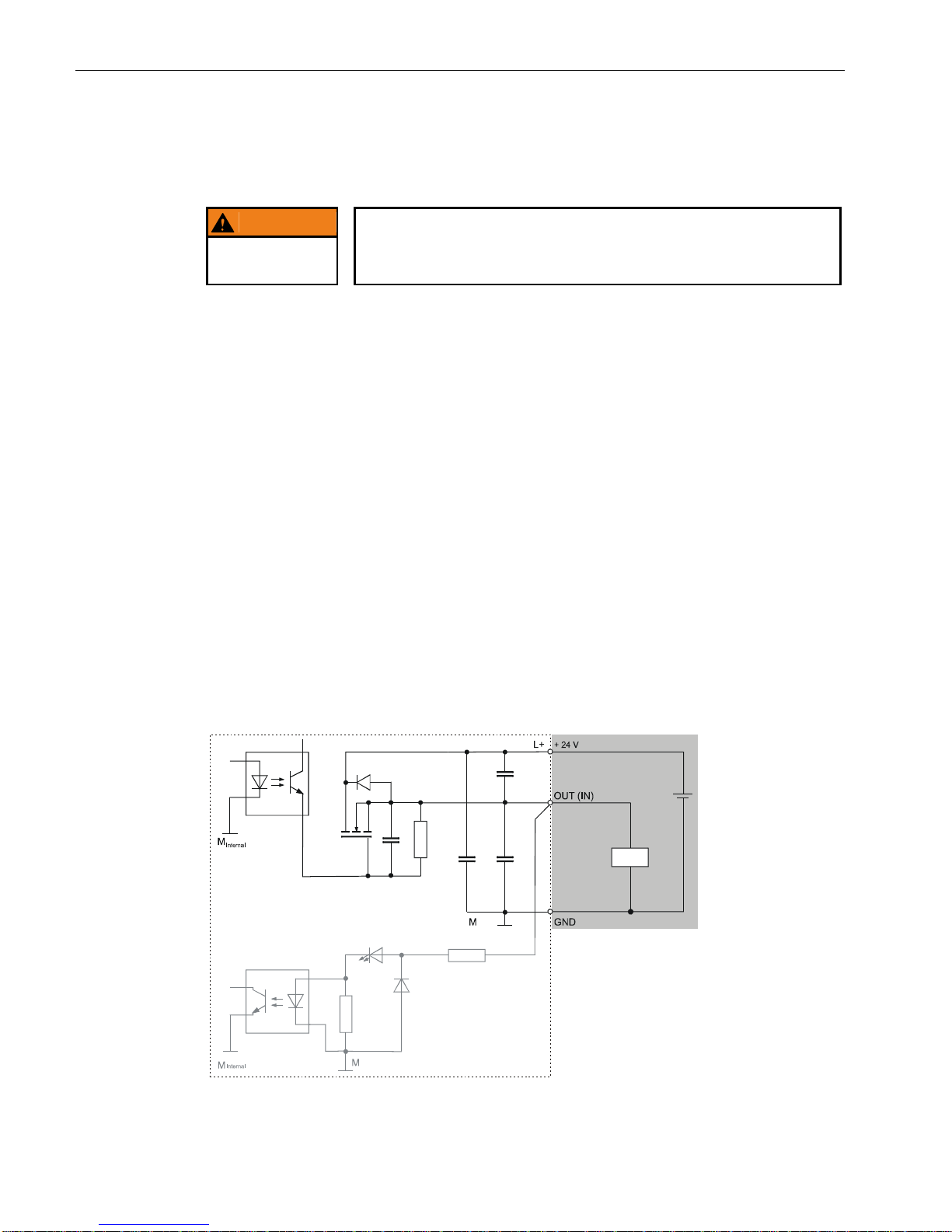
USER MANUAL 1.10 | DC1000 DIALOG-CONTROLLER
Berghof Automation GmbH | Harretstrasse 1 | 72800 Eningen | www.berghof.com
DC1000_HB_en_2D0982010ZD00.docx | 2VF100124FE08.docx
86
4.1.6. Digital outputs, positive switched
WARNING
Voltages of > 32 V and / or feed back can destroy the module.
This represents a fire hazard!
Each digital output can also be used as an input. When used as an input, the information provided under
“Digital inputs” applies.
Outputs
The outputs are positively switching 24 V outputs (2-wire). Output current max. 500 mA per output. The
outputs have a common reference potential (GND). Power supply is separate from the module electronics
supply (refer to “Pin assignment”). If there is no data connection to the CPU or if the internal module supply
is inadequate the outputs independently switch to “0” (LOW).
Protected output
All outputs are protected by an internal current limiter and thermal overload protection. In case of an overload, the current limiter switches the overloaded output off. Once the overload has been corrected and the
unit has cooled down the output can be reactivated via the program. A quick deactivation using a terminal
voltage of 50 V referenced to L+ protects all outputs against induced voltage peaks from inductive loads. If
feedback or the quick deactivation produces thermal loads, the overload protection may also be prematurely
tripped by uninvolved outputs.
Operating status
The status of each output is indicated by a yellow status LED on the front of the module. The LEDs are
spatially assigned to the connection terminals. The LED is on when the associated output is activated, that is,
when it is logical “1” (HIGH).
2VF100011DG01.cdr
Basic output
circuit diagram
Page 87
USER MANUAL 1.10 | DC1000 DIALOG-CONTROLLER
Berghof Automation GmbH | Harretstrasse 1 | 72800 Eningen | www.berghof.com
2VF100124FE08.docx | DC1000_HB_en_2D0982010ZD00.docx
87
Digital output data
Module data
Number of outputs
8 (max. 12 if the I/O is used as an output)
Type of output
Semiconductor, non-saving
Protected circuit for inductive loads
Quick deactivation, 50 V terminal voltage (typical) against
+24 V
Power dissipation resulting from
deactivation
Max. 0.5 W / output; max. 4 W / module
Status indicator
None
Diagnostic function
None
Load connection
Total load (100%)
6 A (12 x 0.5 A)
Overload protection
Yes, for thermal overloads.
Activation of the thermal overload protection may influence
adjacent outputs.
Short circuit protection1)
Activation threshold
Yes, electronic current limiter min. 0.5 A; typically 0.9 A.
1)
Current is electronically limited. Activation of the short circuit protection results in a thermal overload
which activates the thermal overload protection.
Output delay
from “0” to “1”
from “1” to “0”
Max. 0.5 ms
Max. 0.5 ms
Output capacitance
< 20 nF
Reference voltage
Voltage drop (at reference current)
DC +24 V
< 0.5 V
Reference current for “1” signal
Leakage current for “0” signal
0.5 A
Max. 0.1 mA
Total current, all outputs
(horizontal installation on vertical panel)
Max. 6 A (12 x 0.5)
Lamp load (DC +24 V)
Max. 6 W
Parallel switching of two outputs
for logical linkage
to increase performance
Permissible
Prohibited
Insulation resistance
Reference voltage
0 V < Ue < 50 V
Test voltage up to an altitude of 2000 m
DC 500 V
Page 88
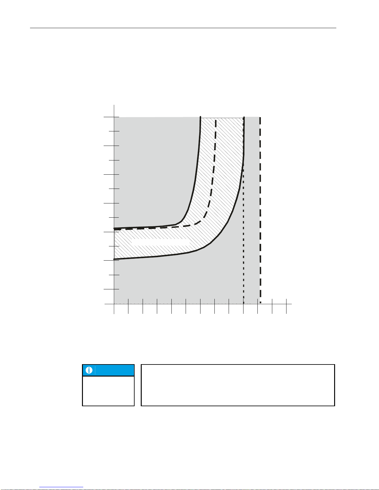
USER MANUAL 1.10 | DC1000 DIALOG-CONTROLLER
Berghof Automation GmbH | Harretstrasse 1 | 72800 Eningen | www.berghof.com
DC1000_HB_en_2D0982010ZD00.docx | 2VF100124FE08.docx
88
2VF100021DG01.cdr
NOTICE
No assurance as to whether a shutdown or a return to the working range
will occur can be made within the current limiter scatter band. Therefore,
this state should be avoided!
The output will again be operational once the overload has been corrected and
the unit has cooled down.
R
L
[Ohm]
2
3
4
5
10
20 30 40 50 100 2001
0
0,1
1
10
100
1000
10000
100000
0
t
p
[ms]
UB18 V
I
max
2 A
Tu0 °C
=
=
=
UB24 V
I
max
1 A
Tu25 °C
=
=
=
UB30 V
I
max
0,7 A
Tu50 °C
=
=
=
Overload behavior of the digital outputs
full-load
full-load
unload
Output ON
Output OFF
Switching Off by
thermal overload
Safety clearance
Current limit scatter band
Current limiting range
Within the current-limit scatter band the reaction of current limiting is undefined.
Page 89
USER MANUAL 1.10 | DC1000 DIALOG-CONTROLLER
Berghof Automation GmbH | Harretstrasse 1 | 72800 Eningen | www.berghof.com
2VF100124FE08.docx | DC1000_HB_en_2D0982010ZD00.docx
89
4.1.7. Digital input/output pin assignments
Connection
Signal
name
Configured as
Note
Digital I/O
TPU-I/O
X12 9 L1+
Feed
X12
X9
X7
X6
X1
X2
1 … 8
9
1 … 9
1 … 9
9
9
M1
GND for module and I/O feed
X4
X5
1 … 9
1 ... 9
+24 V =
I/O feed
Across L1+
X1
1
IN1
Digital IN +24 V
Counter input, +24 V
Form encoder 1
2
IN2
Digital IN +24 V
Counter input, +24 V
3
IN3
Digital IN +24 V
Counter input, +24 V
Form encoder 2
4
IN4
Digital IN +24 V
Counter input, +24 V
5
IN5
Digital IN +24 V
6
IN6
Digital IN +24 V
7
IN7
Digital IN +24 V
8
IN8
Digital IN +24 V
X2
1
IN9
Digital IN +24 V
2
IN10
Digital IN +24 V
3
IN11
Digital IN +24 V
4
IN12
Digital IN +24 V
5
I/O13
Digital I/O +24 V
6
I/O14
Digital I/O +24 V
7
I/O15
Digital I/O +24 V
8
I/O16
Digital I/O +24 V
X9
1
OUT1
Digital OUT +24 V
2
OUT2
Digital OUT +24 V
3
OUT3
Digital OUT +24 V
4
OUT4
Digital OUT +24 V
5
OUT5
Digital OUT +24 V
6
OUT6
Digital OUT +24 V
7
OUT7
Digital OUT +24 V
8
OUT8
Digital OUT +24 V
Page 90
USER MANUAL 1.10 | DC1000 DIALOG-CONTROLLER
Berghof Automation GmbH | Harretstrasse 1 | 72800 Eningen | www.berghof.com
DC1000_HB_en_2D0982010ZD00.docx | 2VF100124FE08.docx
90
Groups of 2 inputs can be combined to form a quadrature encoder for evaluation.
Function
Input 1
Input 2
Encoder 1
IN 1 (X1)
IN 2 (X1)
Encoder 2
IN 3 (X1)
IN 4 (X1)
The encoder values are only reset (0) when the unit is switched on or rebooted after a reset.
Encoder interface
Page 91
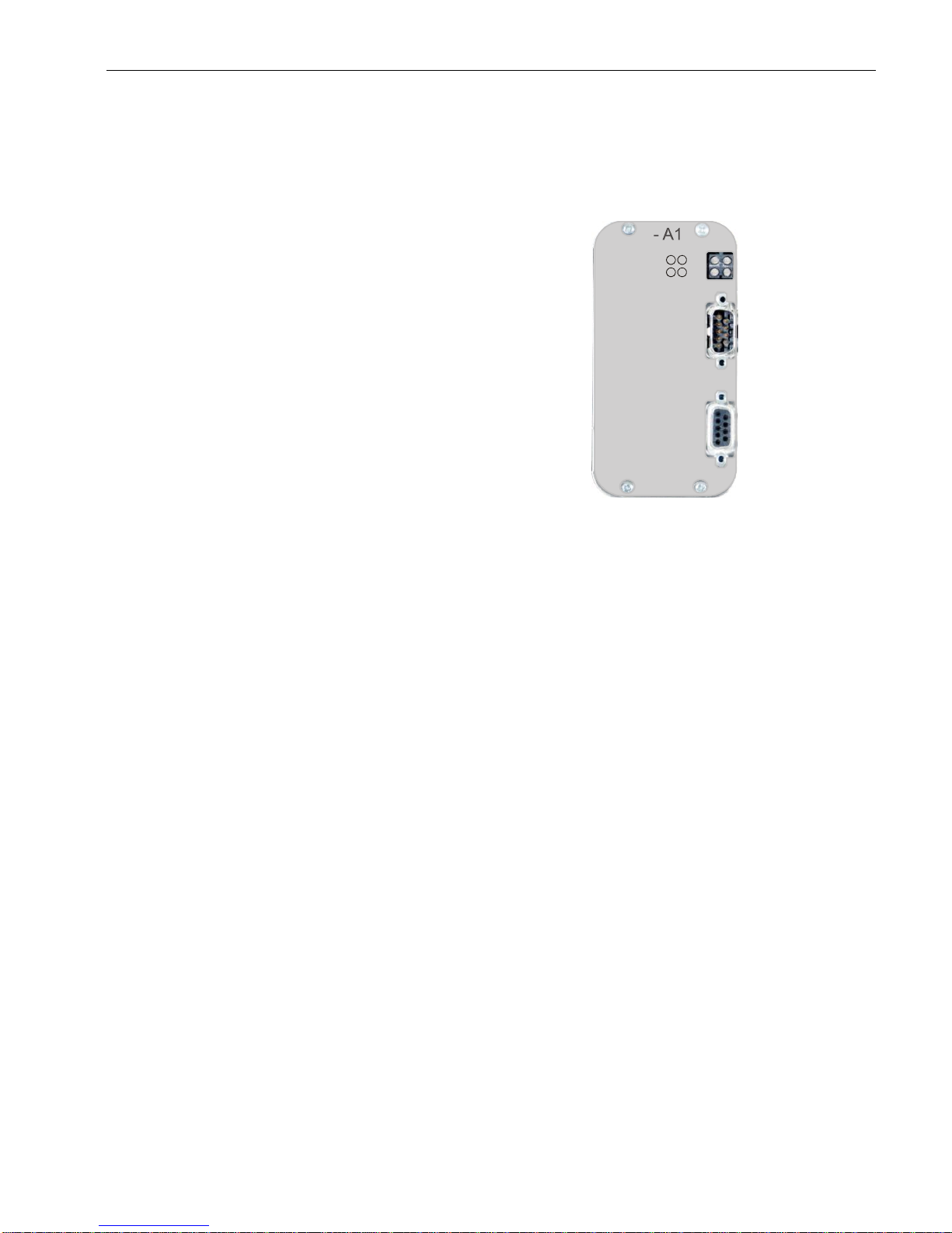
USER MANUAL 1.10 | DC1000 DIALOG-CONTROLLER
Berghof Automation GmbH | Harretstrasse 1 | 72800 Eningen | www.berghof.com
2VF100124FE08.docx | DC1000_HB_en_2D0982010ZD00.docx
91
4.2. PROFIBUS-MASTER card
The PROFIBUS-MASTER card is a PROFIBUS-MASTER module, permanently
installed in a Dialog-Controller.
2VF100308DG00.cdr
Performance features – an overview
PROFIBUS-DP Master bus module
Max. of 125 slave nodes can be connected
Max. 3 kbyte process data (1536 byte input and 1536 byte output data)
Baud rates 9600 bit/s - 12 Mbit/s
Potential isolated PROFIBUS-MASTER RS485 interface with integrated DC/DC converter and opto-
couplers
Cyclic DP-Master services
The scope of supply consists of:
PROFIBUS-MASTER card installed in the Dialog-Controller
Short description
Scope of supply
Indicators
X1
Diag.
X2
Profibus
DC Profibus-DP M
Database
Comm.
Master Token
2
134
Page 92
USER MANUAL 1.10 | DC1000 DIALOG-CONTROLLER
Berghof Automation GmbH | Harretstrasse 1 | 72800 Eningen | www.berghof.com
DC1000_HB_en_2D0982010ZD00.docx | 2VF100124FE08.docx
92
4.2.1. Technical data
Module data
Versions / part no.
Only available as a built-in module
Dimensions, WxHxD [mm]
56.5x108x8
Weight
Approx. 100 g
Operating temperature
range
5 °C to 55 °C (condensation free) Convection cooling ensured
EMI, protection class, insulation test, protection type (installed)
Certification
CE, UL, cUL
Interference emission
EN 61000-6-4, industrial application
Interference resistance
EN 61000-6-2, industrial application
Protection class
III
Insulation resistance
EN 61131-2; DC 500 V test voltage
Protection type
IP 20
Supply voltage, current consumption
Module electronics power
supply
(connection voltage)
5 V / max. 350 mA from the Dialog-Controller’s mains power supply
PROFIBUS-MASTER interfaces
Number and type of interfaces
1 PROFIBUS-MASTER DP interface for connecting a max. of 125 slave
nodes
Potential isolation
Yes
Connection technique
9-pin, Sub-D
Operating and display elements
Display elements
4 diagnostic LEDs
Page 93
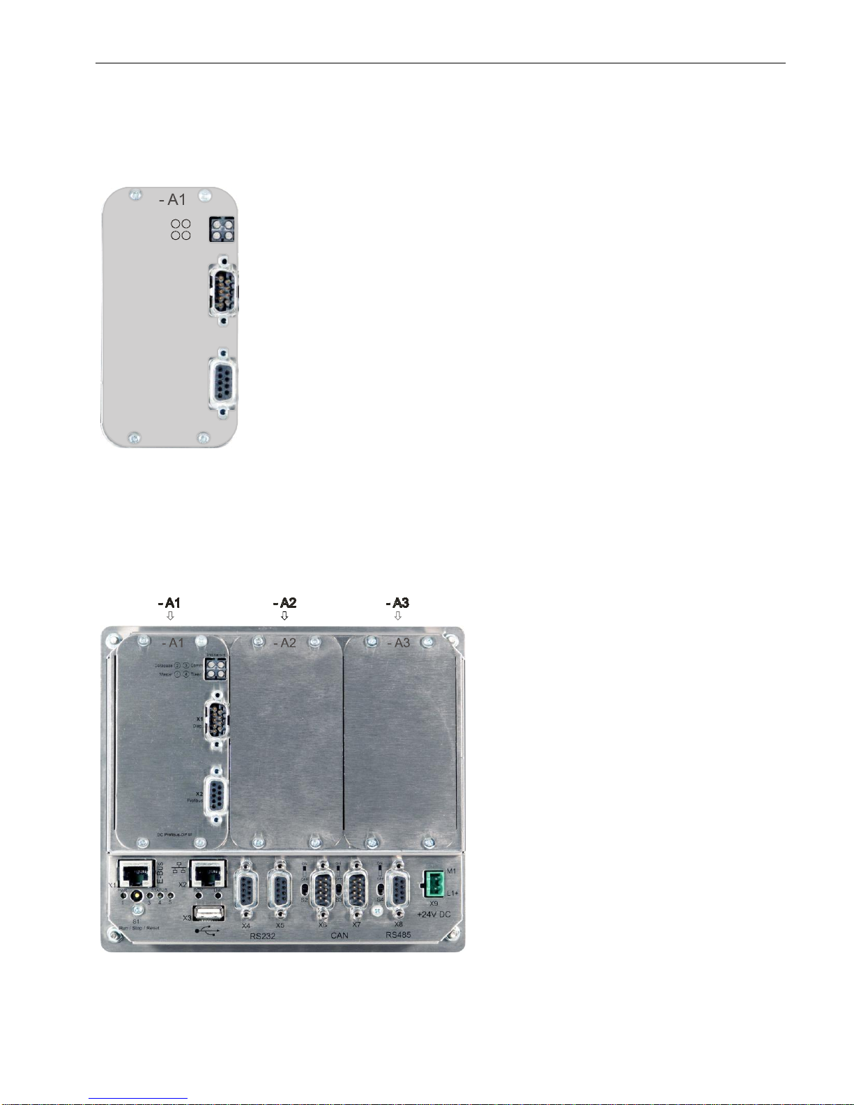
USER MANUAL 1.10 | DC1000 DIALOG-CONTROLLER
Berghof Automation GmbH | Harretstrasse 1 | 72800 Eningen | www.berghof.com
2VF100124FE08.docx | DC1000_HB_en_2D0982010ZD00.docx
93
4.2.2. Front view and pin assignment
2VF100308DG00.cdr
External power supply
The PROFIBUS-MASTER communications interface is supplied from the Dialog-Controller's power supply.
Installation
The PROFIBUS-MASTER card is factory installed and may only be installed in the Dialog-Controller in the
position shown in the figure below.
2VF100309DG00.cdr
Pin overview
Indicators
X1
Diag.
X2
Profibus
DC Profibus-DP M
Database
Comm.
Master Token
2
134
Page 94
USER MANUAL 1.10 | DC1000 DIALOG-CONTROLLER
Berghof Automation GmbH | Harretstrasse 1 | 72800 Eningen | www.berghof.com
DC1000_HB_en_2D0982010ZD00.docx | 2VF100124FE08.docx
94
The embedded PROFIBUS-MASTER bus module is a PROFIBUS DP Master. The module has been tested for
conformity with the PROFIBUS standard and for inter-operability with many leading PROFIBUS slave devices. The onboard microprocessor automatically performs all PROFIBUS bus traffic thus completely reliving
the automation device’s main processor of any PROFIBUS protocol processing.
The PROFIBUS-MASTER module supports a max. of 125 slaves with up to 3 kbyte of I/O data. All baud rates
from 9.6 kbit/s to 12 Mbit/s can be set. All cyclic PROFIBUS services are available.
PROFIBUS-X2 (jack) pin assignment
Pin
Signal
Description
1
N.C.
Do not connect
2
N.C.
Do not connect
3
B
RS485 signal
4
RTS
Ready to send
5
GND
Bus ground
6
+5 V
Bus (output)
7
N.C.
Do not connect
8
A
RS485 signal
9
N.C.
Do not connect
Diag.–X1 (pins) pin assignment
Pin
Signal
Description
1
N.C.
Do not connect
2
RxD
RS232 signal
3
TxD
RS232 signal
4
N.C.
Do not connect
5
GND
Bus ground
6
N.C.
Do not connect
7
N.C.
Do not connect
8
N.C.
Do not connect
9
N.C.
Do not connect
PROFIBUS-MASTER
interface
galvanically isolated
field bus interface
serial diagnostics
interface
Page 95
USER MANUAL 1.10 | DC1000 DIALOG-CONTROLLER
Berghof Automation GmbH | Harretstrasse 1 | 72800 Eningen | www.berghof.com
2VF100124FE08.docx | DC1000_HB_en_2D0982010ZD00.docx
95
NOTICE
All application and diagnostic data are set up via the CODESYS controller configuration or are provided by the application. Therefore, the diagnostic interface
cannot be used in an application-specific manner.
Termination
The PROFIBUS-MASTER has a linear topology. It must be terminated at both ends. The PROFIBUSMASTER module is not equipped with any internal terminating resistors and we therefore recommend the
use of a plug with switchable termination.
Baud rate
The baud rate is set in the CODESYS controller configuration.
GSD file
The PROFIBUS-MASTER module is integrated in the CODESYS controller configuration with a GSD file. As
of Version 1.10.0, this GSD file will be part of the Berghof Target installation package.
Indicator LEDs
Indicator
Signal
Description
1
Master
Green:
Operating mode
Green, flashing:
Delete mode
Red:
Stop mode
Off:
Offline
2
Database
Green:
Databank OK
Green, flashing:
Database load procedure running
Red:
Database invalid
Off:
No database available
3
Comm.
Green:
Data exchange with all configured slaves
Green, flashing:
Data exchange with at least 1 configured slave
Red:
Bus error, e.g., due to a short circuit or configuration error
Off:
No data exchange
4
Token
Green:
Module has the token
Off:
Token not at the module
All Red:
Fatal error
Page 96
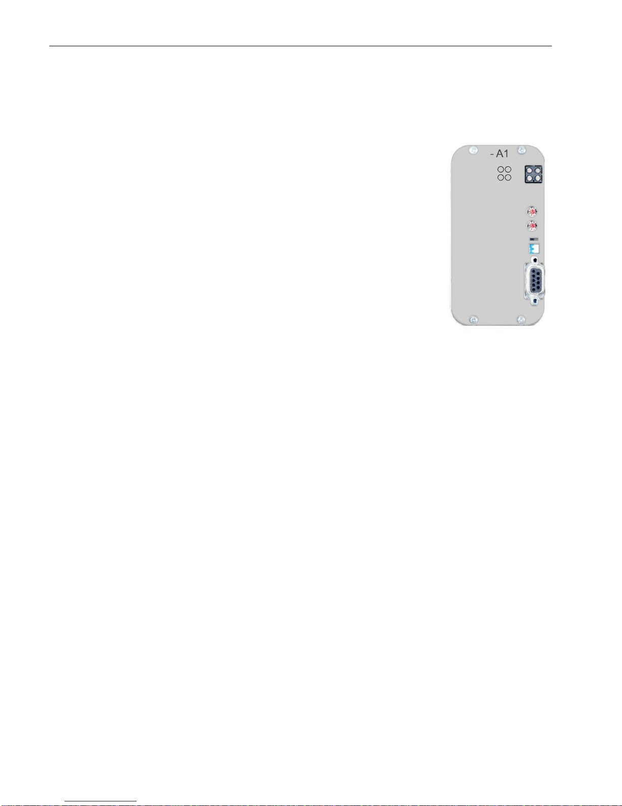
USER MANUAL 1.10 | DC1000 DIALOG-CONTROLLER
Berghof Automation GmbH | Harretstrasse 1 | 72800 Eningen | www.berghof.com
DC1000_HB_en_2D0982010ZD00.docx | 2VF100124FE08.docx
96
4.3. PROFIBUS-SLAVE card
The PROFIBUS-SLAVE card is a PROFIBUS-SLAVE module, permanently installed in a Dialog-Controller.
2VF100310DG00.cdr
Performance features – an overview
PROFIBUS-DP SLAVE bus module
Max. 244 byte input and 244 byte output data (all together 416 byte)
Automatic baud rate recognition, 9600 bit/s - 12 Mbit/s
Potential isolated PROFIBUS-SLAVE RS485 interface with integrated DC/DC converter and
optocouplers
All required DP services as well as user parameter data and device-specific diagnostics
The scope of supply consists of:
PROFIBUS-SLAVE card installed in the Dialog-Controller
Short description
Scope of supply
Indicators
S1
S3
S2
Address x1
Termination
ON OFF
Address x10
X1
Profibus
DC Profibus-DPS
Online Offline
n.c. Error1
2 3
4
Page 97
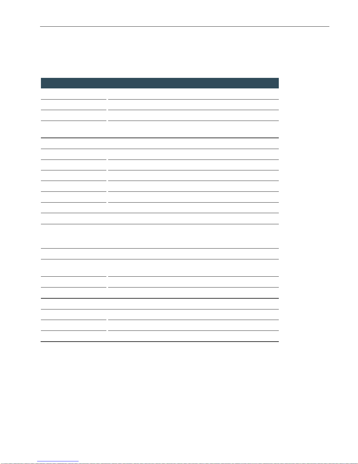
USER MANUAL 1.10 | DC1000 DIALOG-CONTROLLER
Berghof Automation GmbH | Harretstrasse 1 | 72800 Eningen | www.berghof.com
2VF100124FE08.docx | DC1000_HB_en_2D0982010ZD00.docx
97
4.3.1. Technical data
Module data
Versions / part no.
Only available as a built-in module
Dimensions, WxHxD [mm]
56.5x108x8
Weight
Approx. 100 g
Operating temperature
range
5 °C to 55 °C (condensation free) Convection cooling ensured
EMI, protection class, insulation test, protection type (installed)
Certification
CE, UL, cUL
Interference emission
EN 61000-6-4, industrial application
Interference resistance
EN 61000-6-2, industrial application
Protection class
III
Insulation resistance
EN 61131-2; DC 500 V test voltage
Protection type
IP 20
Supply voltage, current consumption
Module electronics power
supply
(connection voltage)
5 V / max. 350 mA from the Dialog-Controller’s mains power supply
PROFIBUS-SLAVE interfaces
Number and type of interfaces
1 PROFIBUS-SLAVE interface DP
Potential isolation
Yes
Connection technique
9-pin, Sub-D
Operating and display elements
Display elements
4 diagnostic LEDs
Address switch
Switches not used for applications
Termination
Switchable terminating resistor
Page 98
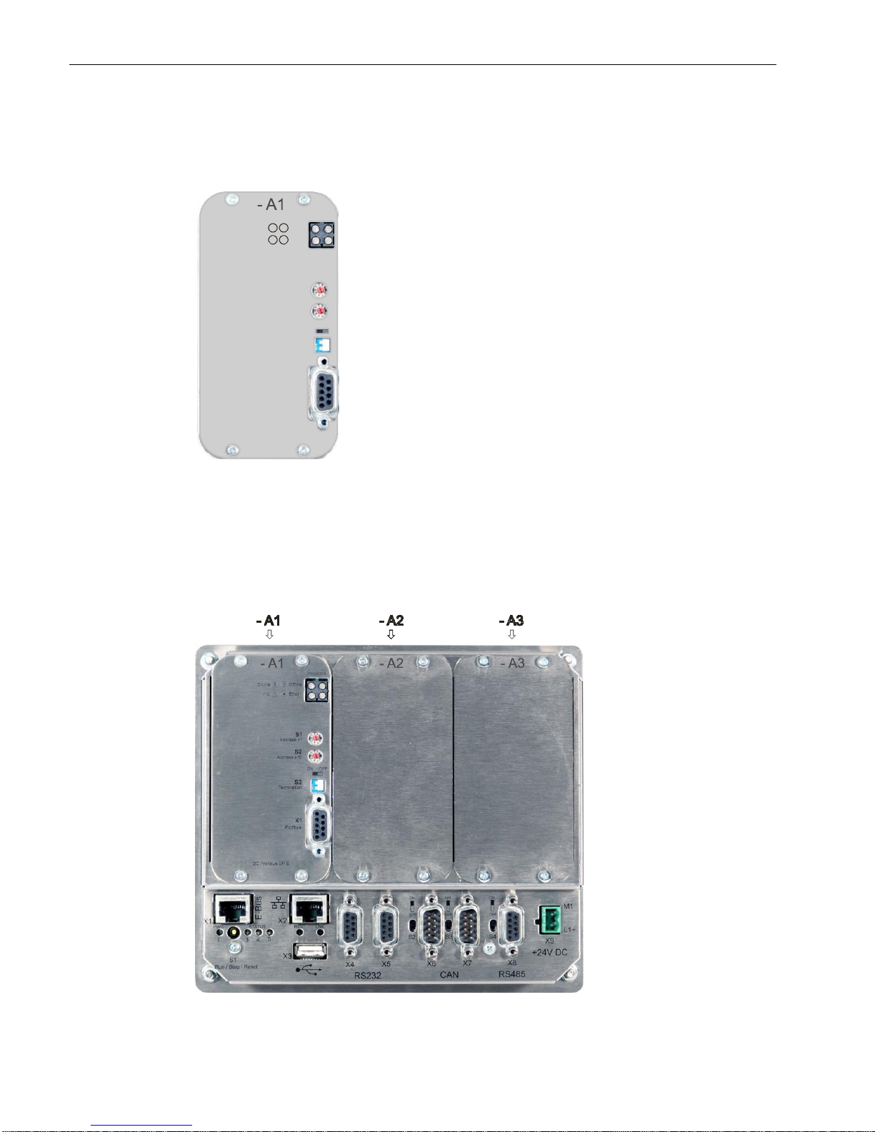
USER MANUAL 1.10 | DC1000 DIALOG-CONTROLLER
Berghof Automation GmbH | Harretstrasse 1 | 72800 Eningen | www.berghof.com
DC1000_HB_en_2D0982010ZD00.docx | 2VF100124FE08.docx
98
4.3.2. Front view and pin assignment
2VF100310DG00.cdr
External power supply
The PROFIBUS-SLAVE communications interface is supplied from the Dialog-Controller's power supply.
Installation
The PROFIBUS-SLAVE card is factory installed and may only be installed in the Dialog-Controller in the position shown in the figure below.
2VF100311DG00.cdr
Pin overview
Indicators
S1
S3
S2
Address x1
Termination
ON OFF
Address x10
X1
Profibus
DC Profibus-DPS
Online Offline
n.c. Error1
2 3
4
Page 99
USER MANUAL 1.10 | DC1000 DIALOG-CONTROLLER
Berghof Automation GmbH | Harretstrasse 1 | 72800 Eningen | www.berghof.com
2VF100124FE08.docx | DC1000_HB_en_2D0982010ZD00.docx
99
The embedded PROFIBUS-SLAVE module is a complete PROFIBUS-DP SLAVE. It contains all analog and
digital components for a high performance PROFIBUS extension circuit. The module is certified and has
been tested for inter-operability with many leading PROFIBUS master subassemblies. The onboard micro-
processor automatically performs all PROFIBUS bus traffic thus completely reliving the automation device’s
main processor of any PROFIBUS protocol processing.
The PROFIBUS module supports a maximum PROFIBUS data width of 244 input bytes and 244 output bytes
as well as all rates from 9.6 kbit/s to 12 Mbit/s.
NOTICE
The PROFIBUS station address is set with the CODESYS controller configuration. Rotary switches S1 and S2 have no effect and can therefore not be used
in an application-specific manner.
PROFIBUS-X1 (jack) pin assignment
Pin
Signal
Description
1
N.C.
Do not connect
2
N.C.
Do not connect
3
B
RS485 signal
4
RTS
Ready to send
5
GND
Bus ground
6
+5 V
Bus (output)
7
N.C.
Do not connect
8
A
RS485 signal
9
N.C.
Do not connect
Termination, S3
The PROFIBUS has a linear topology. It must be terminated at both ends. The PROFIBUS-SLAVE module
has an integrated bus termination which can be activated by a DIP switch (ON position).
Baud rate
The baud rate is automatically detected.
GSD file
The PROFIBUS-SLAVE module is integrated in the CODESYS controller configuration with a GSD file. As of
Version 1.10.0, this GSD file will be part of the Berghof Target installation package.
Indicator LEDs
Four diagnostic LEDs indicate the current operating state and any error messages.
PROFIBUS-SLAVE
interface
galvanically isolated
field bus interface
Page 100
USER MANUAL 1.10 | DC1000 DIALOG-CONTROLLER
Berghof Automation GmbH | Harretstrasse 1 | 72800 Eningen | www.berghof.com
DC1000_HB_en_2D0982010ZD00.docx | 2VF100124FE08.docx
100
Indicator
Signal
Description
1
N.C.
Not used
2
Online
Green:
Online / data exchange permitted
Off:
Not online
3
Offline
Red:
Offline, no data exchange possible
Off:
Not offline
4
Error
Red, flashing at 1 Hz:
Configuration error; initialized data length does not
match configuration
Red, flashing at 2 Hz:
Missing user parameter; initialized data length does not
match configuration
Red, flashing at 4 Hz:
Initialization error in the ASIC
Off:
No diagnostic data available
 Loading...