

Page 1
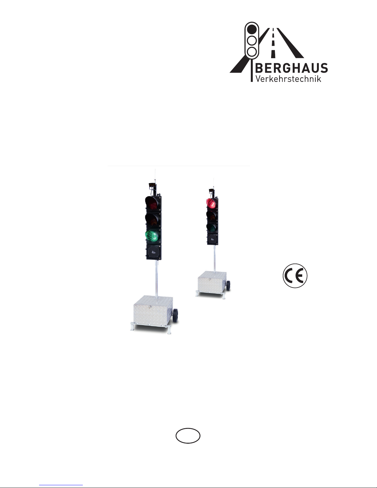
Operating Instructions
Construction Site Traffic
Signal System MPB 4400
GB
Page 2

General explanation of building site signalling equipment
Signal safety
The German regulations of VDE, TL-LSA 97 and RiLSA describe among others the
use ofportable construction site traffic signal systems.
The above regulations stipulate that no signal safety feature as per RiLSA and VDE
0832 is necessary e.g. for construction sites with alternating one-way traffic control
and a clearance speed of up to 30 km/h, insofar as the corresponding authorities have
not imposed any stricter conditions or requirements.
All other construction site traffic signal systems used for controlling traffic at
T-junctions, crossroads or pedestrian crossings must be equipped with a signal safety
feature as per RiLSA and VDE 0832, and fulfil TL-LSA97.
This safety feature requires a feedback message which can be transmitted by radio or
cable. Radio-controlled traffic signals use top-quality radio modules which have been
given an approval number by the German Federal NetworkAgency for electricity, gas,
telecommunications, postal and railway markets (formerly RegTP).
Peter Berghaus GmbH produces and supplies construction site traffic signal
systems and signal safety feature.with without
Page 3

TABLE OF CONTENTS
I. Presentation of the and Manual Device ModelsMPB 4400
Pages 1 to 2
II. Programming / Re-programming
Pages 3 to 58
1. One-Way Alternating-Direction Traffic
Pages 3 to 6
2. One-Way Alternating-Direction Traffic with Special Options
(see Chapters III + IV)
Pages 7 to 12
3. One-Way Alternating-Direction Traffic that is Traffic-Flow
Dependent
Pages 13 to 15
4. One-Way Alternating-Direction Traffic that is Traffic-Flow
Dependent, with Special Options (see Chapters III + IV)
Pages 16 to 21
5. Intersection Traffic
Pages 22 to 26
6. Intersection Traffic with Special Options
(see Chapters III + IV)
Pages 27 to 33
7. Intersection Traffic that is Traffic-Flow Dependent
Pages 34 to 38
8. Intersection Traffic that is Traffic-Flow Dependent
with Special Options (see Chapters III + IV)
Pages 39 to 46
9. Reprogramming or changing the time settings of a radio/cable
traffic signal which has already been commissioned
Pages 46 to 47
10. Reading out data with the handbox during on-going operation
Page 48
Page 4

III. Special Options with Quartz Operation (Night-time Mode)
Page 49
IV. Special Options with Radio and Cable Operation
(Night-time Mode, Day Programmes, Interval matrix ,
Forced Circulation and Data Transmission via PC)
Pages 50 to 53
V. Auxiliary Functions (Manual Operation, Setting the Time
of Day, Selecting Programmes, Version Display and Error
Acknowledgement)
Pages 54 to 64
VI. Control Device / Error Messages for Control Device
Pages 65 to 69
VII. Manual Device / Error Messages for Manual Device
Pages 70 to 72
VIII. Accessories
Page 73
IX. Technical Data
Page 74
X. Radar Detector
Pages 75 to 76
XI. Spare Parts List
Pages 77 to 78
XII. Warranty
Page 80
Page 5

I. Introduction
The is the universal signal equipment for all trafficMPB 4400
situations subject to traffic light control, including installations for the
following traffic patterns: one-way alternating-direction; junctionmerging and pedestrian installations; also for intersection signal
installations with 12 groups and a maximum of 24 signal heads with
control units that are 100% identical in construction.
The installation can be supplied as orQuartz, Cable Quartz, Cable-
Radio Equipment.
In cable as well as in radio mode, the equipment possesses all
monitor features specified by RiLSA:
- Red Light Monitoring
- Green-Green Prevention
- Green Status
- Interval Monitoring (required acc. to RiLSA,
Appendix G.3)
- Watch Dog (computer monitoring)
All data such as signal time plans and malfunctions with date can be
printed out on a printer.
The following operating modes are possible:
1. Fixed time programme as well as fixed time programme with up to
4 daytime programmes
2. Traffic-flow-dependent mode as well as traffic-flow-dependent
mode with up to 4 daytime programmes
3. Traffic-flow-dependent mode with green on demand with up to 4
daytime programmes
4. Flashing and darkness programme
Up to 4 start times with different blocks of days can be entered for all
programmes.
1
Page 6

MANUALDEVICE MODELS
Switching the manual device off and on
Before you can set the manual device into operation, the batteries
(4* Mignon AA) that are supplied with it must first be installed. To do
this, open the battery chamber on the rear side of the device and insert
the batteries (be sure the polarity is correct!).To switch the device on,
briefly press the "ON" key.
The manual device will then display the manual device model. You can
switch off the manual device by holding the #2 key pressed down for ca.
5 seconds.
The display shows the following, depending upon manual device
model:
Chapter II Number 1 + 2
Chapter II Number 3 + 4
Chapter II Number 5 + 6
Chapter II Number 7 + 8
You have different programming possibilities available to you,
depending upon manual device model.These are explained in detail in
the Chapters listed next to the manual device displays.
**M P B 4400**
One Way Traffic
* M P B 4400 VA*
One Way Traffic
**M P B 4400**
Cross-roads
* M P B 4400 VA*
Cross-roads
2
Page 7

1. Input for One-WayAlternating-Direction Traffic
Without traffic-flow dependency and without special
options
You can programme one-way alternating-direction
traffic with this manual device.
Before programming the signal equipment, you should make sure that
the time of day and date are set correctly in the manual device. You can
determine this by switching on the manual device. After approximately
10 seconds, the current time of day and date are presented automatically
in the display. If the information shown is not correct, then reset the
numbers as described in the "Auxiliary Functions" Chapter on page 53
of this manual. Switch further using key #4 until the manual device tells
you to program the traffic light. In doing so, the manual device requests
a variety of entries. You can alter the date by using the keys #1 and #3.
The number that is currently valid will be flashing. If you hold the key
pressed down for a longer time, then the numbers change more quickly.
The display shows:
Select with the keys #1 and #3 the desired operating mode, for example
"Quartz" for quartz operation.
Withkey #4 you then movefurther to the point for entering the
Please select:
Quartz Radio Cable
Site length:
>-< 50 m >+<
**M P B 4400**
One Way Traffic
3
Page 8

Here you can alter the length of the roadworks site using the keys #1
and #3.
Once the value is set, proceed further with key #4.
The current speed will be flashing. Set the required speed for within the
roadworks site.
Then press key #4 again. The following will appear:
These two times have been calculated by the manual device.
For safety reasons, the displayed periods for traffic-clearing must be
considered irreducible minimums. It is however possible to increase the
times using key #3--to different extents, if desired: Thus, at a road
works site on a mountain, for example, the ascending traffic can be
allowed a longer traffic-clearing period. Traffic-clearing period #1 ends
when traffic light #2 has finished its green signal.
Press key #4 once again and follow the display in the manual device:
The displayed value in the line in which the arrow is blinking can be
altered using keys #1 and #3. With key #4, one moves one line down,
and can then alter the time setting there.
At this point, all the entries in the manual device are completed.
Press key #4 once again. The display shows:
Clr.time 1 => 10s
Clr.time 2 = 10s
Select: (km/h)
10 40 50 7030
Grn.time 1 => 5s
Grn.time 2 = 5s
Making
signalplan
4
Page 9
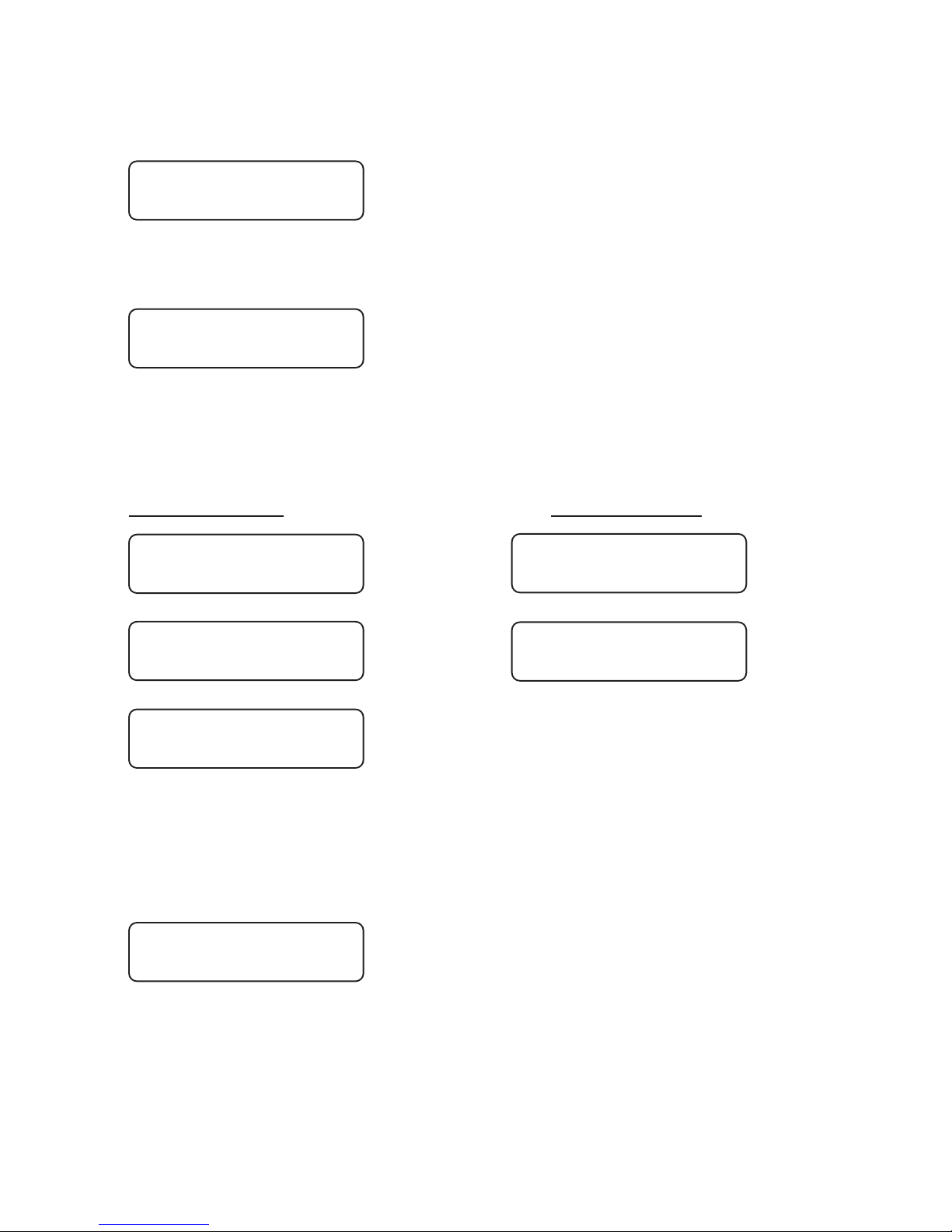
After the formulation of the signal plan, the display switches to the
following message:
Plug the device into the first traffic light (traffic light #1). Switch the
traffic light on. The following must be visible in the traffic light display:
a.) with Quartz Operation
Press key #4 on the manual device. The data from the hand device will
be transmitted to the first traffic light (traffic light #1).
Manual device: Control device:
The second traffic light must still now be programmed. Plug the manual
device into the second traffic light and switch the traffic light on,
waiting then a moment until the following is displayed in the control
device:
Now press key #4 on the plugged-in manual device. The data will be
transmitted into the second traffic light (traffic light #2). The entire
equipment (traffic light #1 and traffic light #2) synchronise themselves
automatically and start the programme flow.
Put box into
Unit 1 >4<
12,8 V Light ??
No data !
12,8 V Light ??
No data !
Sending to light
Datablock: 159 /
12,8 V Light 1
Receiving /
Transmission
>> OK <<
Transmission
>> OK <<
1 light correct
programmed
5
Page 10
b.) with Radio Cable Operationor without Special Options
The selection proceeds as described in Item 1.2. You select however,
depending upon the connection mode, not quartz but either radio or
cable instead. For this you need programme only one traffic light with
the manual device. Once you have ,linked the equipment with cables
switch on .one traffic light
Once it is programmed, this will be known as traffic light #1.
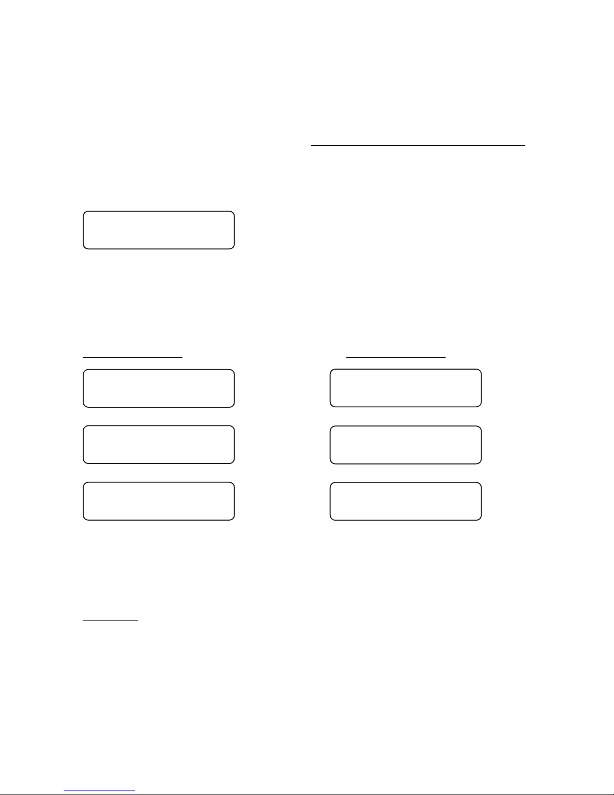
The following must be displayed in the control device:
The cable linkage is not required with a radio installation. Programme
the first traffic light (traffic light #1) with the manual device, for which
you plug the manual device into the traffic light and press key #4 after
the display calls for it. The two displays then show the following:
Manual device: Control device:
After switching on traffic light #2, the programme is transmitted by
radio or cable to the other traffic light (traffic light #2) and the
installation starts up completely automatically.
Warning: In the event of a data loss at traffic light #1 or #2 (through
activation of the on/off switch), the entire installation must be reprogrammedin the case of a .radio signal installation
Manual Options: (Flashing, Lights Off, All-Red and Programme
Selection) The procedural methods with manual options can be found in
Chapter V"Auxiliary Functions", on page 53 of this manual.
12,8 V Light 1
Light 2 missing !
12,8 V Light ??
No data !
6
Sending to light
Datablock: 159 /
12,8 V Light 1
Receiving /
Transmission
>> OK <<
Transmission
>> OK <<
1 light correct
programmed
Page 11

2. Input for One-Way Alternating-Direction Traffic
Radio or cable operation without traffic-flow dependency,
but with special options such as Nighttime Mode, Day
Programmes, Interval matrix, Forced Circulation and Data
Transmission via PC
With this manual device you can programme one-way alternatingdirection traffic without traffic-flow dependency, although with
special options. Directions for setting the special options can be
found starting on page 49 of this manual.
Before programming the signal equipment, you should make sure that
the time of day and date are set correctly in the manual device. You can
determine this by switching on the manual device. After approximately
10 seconds, the current time of day and date are presented automatically
in the display. If the information shown is not correct, then reset the
numbers as described in the "Auxiliary Functions" Chapter on page 53
of this manual.
Switch further using key #4 until the manual device tells you to
programme the traffic light. In doing so, the manual device requests a
variety of entries.You can alter the date by using the keys #1 and #3. The
number that is currently valid will be flashing.
If you hold the key pressed down for a longer time, then the numbers
change more quickly.
The display shows:
Select with the keys #1 and #3 the desired operating mode, for example
"Cable" or "Radio" (the only special option available with quartz
operation is Night-time Mode).
Withkey #4 you then movefurther to the point of entering the
Please select:
Quartz Radio Cable
7
**M P B 4400**
One Way Traffic
Page 12

Here you can alter the length of the roadworks site using the keys #1
and #3.
Once the value is set, proceed further with key #4.
The current speed will be flashing. Set the required speed for within the
roadworks site.
Then press key #4. The following will appear:
These two times have been calculated by the manual device. For safety
reasons, the displayed periods for traffic-clearing must be considered
irreducible minimums. It is however possible to increase the times
using key #3--to different extents, if desired: Thus, at a road works site
on a mountain, for example, the ascending traffic can be allowed a
longer traffic-clearing period. Traffic-clearing period #1 ends when
traffic light #2 has finished its "Green".
Press key #4 once again and follow the display in the manual device. If
you have selected Daytime Programme as a special option, then the
following display appears. The method used to activate the special
options is described in the annex under "Special Options".
Here you are called upon to enter the 1st Daytime Programme:
The displayed value in the line in which the arrow is blinking can be
altered using keys #1 and #3. With key #4, one moves one line down,
and can then alter the time setting there.
Input >4<
Dayprogram 1
Site length:
>-< 50 m >+<
Select: (km/h)
10 40 50 7030
Clr.time 1 => 10s
Clr.time 2 = 10s
Grn.time 1 => 5s
Grn.time 2 = 5s
8
Page 13

When you are carrying out a re-programming, you have the opportunity
of deleting old switch points that may be left over from a previous
programming. For this, select "Yes", and confirm your choice with key
#4.
Once you have completed these entries, the manual device will ask you
for 4 switch points for the entered Daytime Programme #1. This means
that once you have entered a Daytime Programme, you can have it start
itself as many as four times a day, at the different times that you select:
00:00 means in this connection no input. For midnight, you must enter
24:00
After entering the starting time, you will be called upon to specify the
days on which the programme is to be used.
If you have selected two or more Daytime Programmes, then you will
now be called upon to enter these as described above (Enter Daytime
Programme #2).
After this entry, you have the opportunity of determiningthe Night-time
Mode, if you have activated it as described in the annex under "Special
Options".
If you select "Yes" here, then you will be called upon to programme the
Night-time Mode:
Here you are asked to select 4 switch points for the Night-time Mode.
This means you can have the Night-time Mode start itself as many as
four times a day, at the different times that you select:
Switchp. clear ?
yes no
Switchp. 1 Pro 1
Start:>06:00 Uhr
Select Days
all Mo-Fr Sa-So
Nightmode:
yes no
Input >4<
Nightprog. darkl
9
Page 14

00:00 means in this connection no input. For midnight, you must
therefore enter 24:00
After entering the starting time, you will be called upon to specify the
days on which the programme is to be used.
Afterwards, you have the opportunity to set the Night-time Mode for
Flashing:
Here you are asked to select 4 switch points for the Night-time Mode.
This means you can have the Night-time Mode start itself as many as
four times a day, at the different times that you select:
00:00 means in this connection no input. For midnight, you must
therefore enter 24:00
After entering the starting time, you will be called upon to specify the
days on which the programme is to be used.
After you have selected the days, (press key #4), the following display
appears, if you have set the Interval Matrix under Special Options to
"Yes":
Using the keys #1 and #3, you can select whether or not you wish to
activate the Interval Matrix.
The previous setting flashes. The Interval Matrix is an additional
control function for monitoring the minimum traffic-clearing periods.
Switchp. 1 off
Start:>23:00 Uhr
Switchp. 1 flash
Start:>22:00 Uhr
Meantimes
yes no
Select Days
all Mo-Fr Sa-So
Input >4<
Nightprog. flash
Select Days
all Mo-Fr Sa-So
10
Page 15

The Interval Time is the period of time between the end of the green
phase (e.g. of traffic light #1) and the beginning of the clear signal
(green) for a coming traffic flow that intersects or merges (in this case
traffic light #2, as one-way alternating-direction traffic operation was
selected). Traffic-clearing time computation proceeds automatically
for one-way alternating-direction traffic.
After selection of the Interval Matrix, the following display appears:
For one-way alternating-direction traffic, the intervals are adopted
automatically from the traffic-clearing times, and can no longer be
altered. This serves for adoption of the minimum traffic-clearing times.
Confirm this with key #>4<. Now the display appears for setting the
interval from traffic light #2 to traffic light #1 (this, too, will be
automatically adopted):
At this point, all the entries in the manual device are completed. Press
key #4 once again. The display shows:
After the formulation of the signal plan, the display switches to the
following message:
Switch on a traffic light (which then automatically becomes traffic light
#1). The following must be visible in the traffic light display:
Plug the device into the first traffic light (traffic light #1). Press key #4
on the manual device. The data from the hand device will be transmitted
to the first traffic light (traffic light #1).
from 1 => 2
10 sec
from 2 => 1
10 sec
Making
signalplan
Put box into
Unit 1 >4<
12,8 V Light ??
No data !
11
Page 16
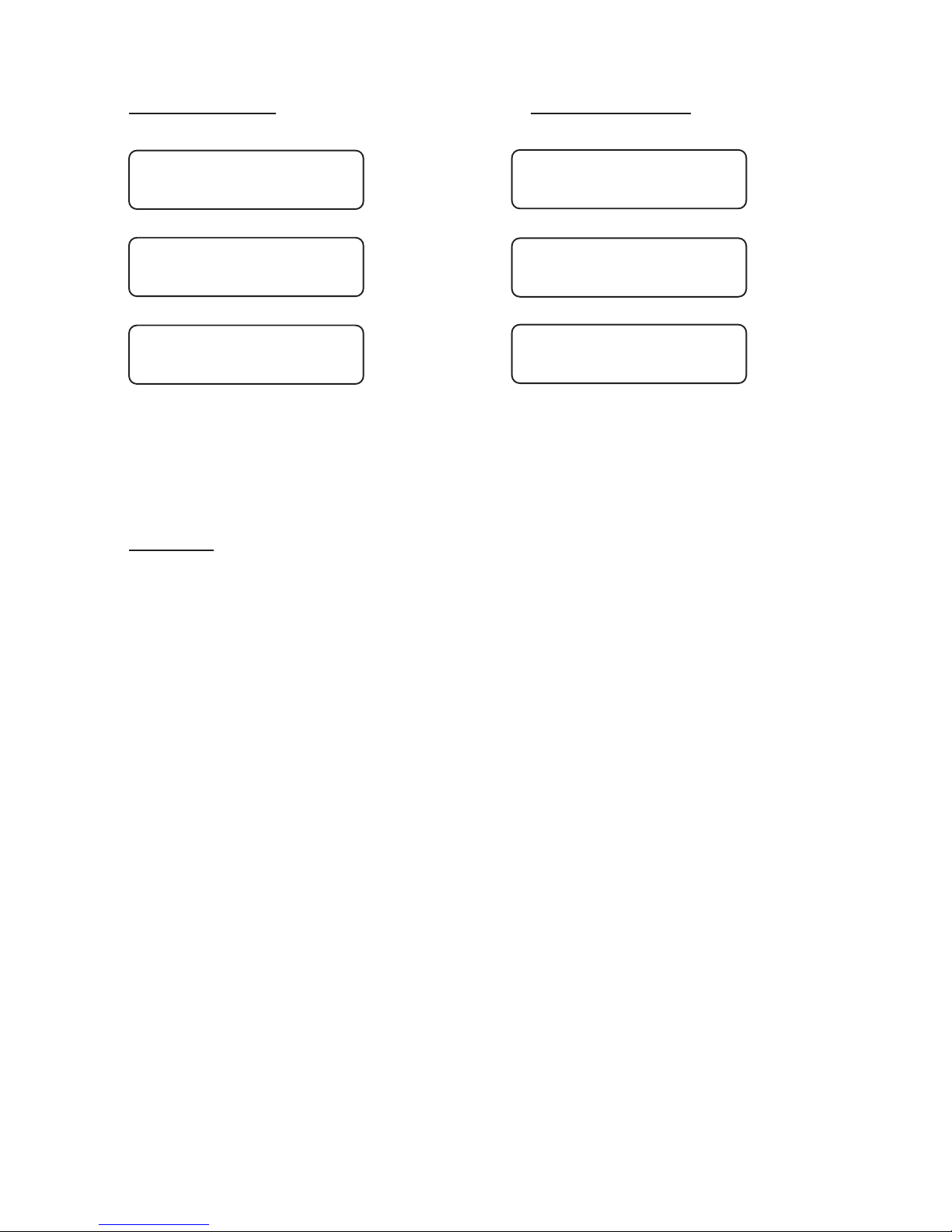
Manual device Control device::
After switching on traffic light #2, the programme is transmitted by
radio or cable to the other traffic light (traffic light #2) and the
installation starts up completely automatically.
Warning: In the event of a data loss at traffic light #1 or #2 (through
activation of the on/off switch), the entire installation must be reprogrammedin the case of a .radio signal installation
Manual Options:
(Flashing, Lights Off, All-Red and Programme Selection)
The procedural methods with manual options can be found in ChapterV
"Auxiliary Functions", on page 53 of this manual.
12
12,8 V Light 1
Light 2 missing !
Sending to light
Datablock: 159 /
12,8 V Light 1
Receiving /
Transmission
>> OK <<
Transmission
>> OK <<
1 light correct
programmed
Page 17

3. Input for One-Way Alternating-Direction Traffic
With traffic-flow dependency but without special options
With this manual device you can programme one-way alternatingdirection traffic with traffic-flow dependency, although without
special options.
Before programming the signal equipment, you should make sure that
the time of day and date are set correctly in the manual device. You can
determine this by switching on the manual device.
After approximately 10 seconds, the current time of day and date are
presented automatically in the display. If the information shown is not
correct, then reset the numbers as described in the "Auxiliary
Functions" Chapter on page 53 of this manual. Switch further using key
#4 until the manual device tells you to programme the traffic light. In
doing so, the manual device requests a variety of entries. You can alter
the date by using the keys #1 and #3. The number that is currently valid
will be flashing.
If you hold the key pressed down for a longer time, then the numbers
change more quickly.
The display shows:
Select with the keys #1 and #3 the desired operating mode, for example
"Cable" or "Radio". If "Quartz" is selected, then traffic-flowno
dependency is possible.
With key #4 you then move further to the point of entering the trafficflow dependency:
Traffic related:
yes no
Please select:
Quartz Radio Cable
13
**M P B 4400 VA**
One Way Traffic
Page 18
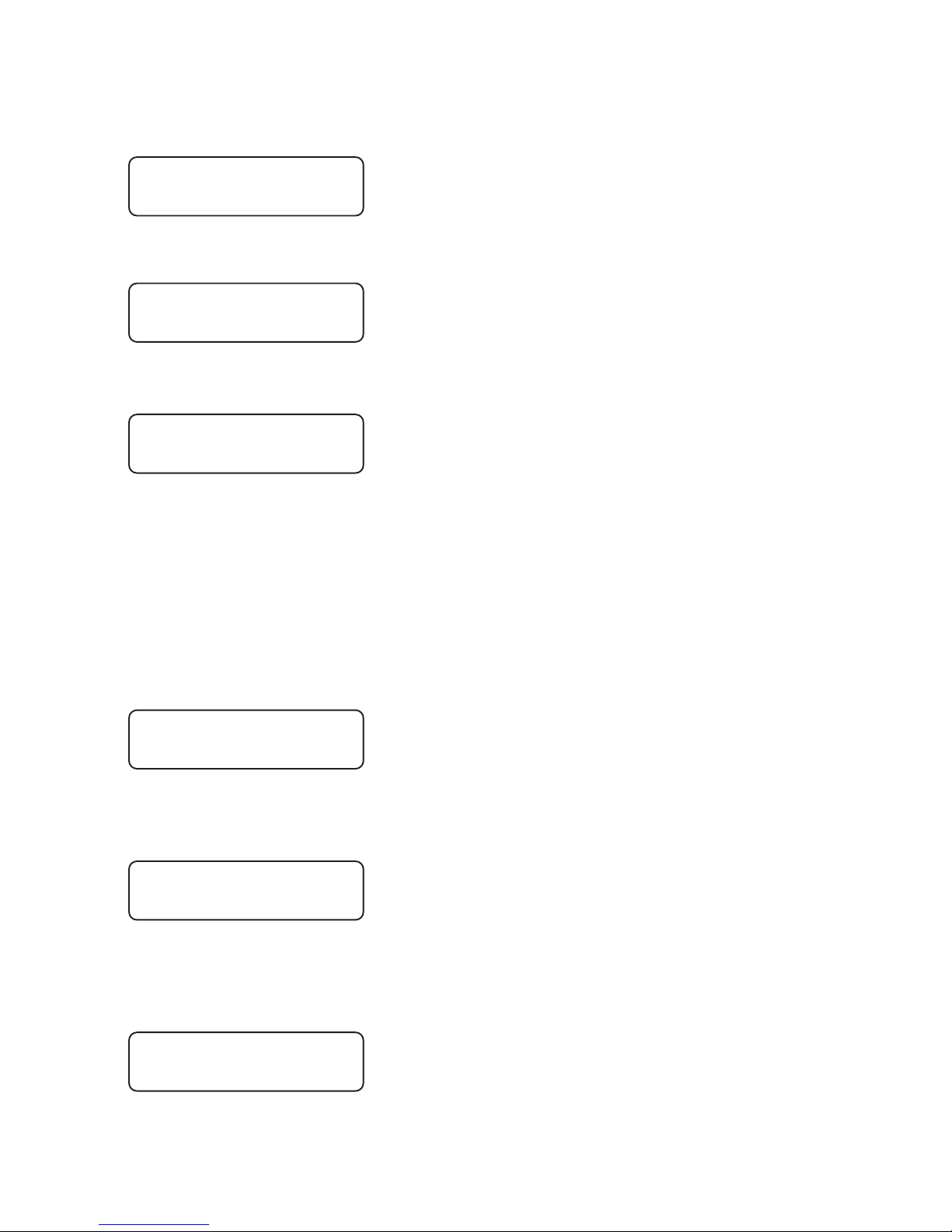
Set the traffic-flow dependency to "Yes" ("Yes" flashes) and confirm the
selection with key #4. The manual device display shows the following:
Here you can alter the length of the roadworks site using the keys #1
and #3. Once the value is set, proceed further with key #4.
The current speed will be flashing. Set the required speed for within the
roadworks site. Then press key #4 again.The following will appear:
These two times have been calculated by the manual device. For safety
reasons, the displayed periods for traffic-clearing must be considered
irreducible minimums. It is however possible to increase the times
using key #3 - to different extents, if desired: Thus, at a road works site
on a mountain, for example, the ascending traffic can be allowed a
longer traffic-clearing period. Traffic-clearing period #1 ends when
traffic light #2 has finished its green signal.
Press key #4 once again and follow the display in the manual device:
Now one can set a minimum and a maximum green time for signal
group #1. Continue with key #4.
Now the same entries are made as above, this time for signal group #2.
At this point, all the entries in the manual device are completed. Press
key #4 once again. The display shows:
After the formulation of the signal plan, the display switches to the
Grn2 min => 10s
Grn2 max = 25s
Grn1 min => 10s
Grn1 max = 35s
Site length:
>-< 50 m >+<
Select: (km/h)
10 40 50 7030
Clr.time 1 => 10s
Clr.time 2 = 10s
Making
signalplan
14
Page 19
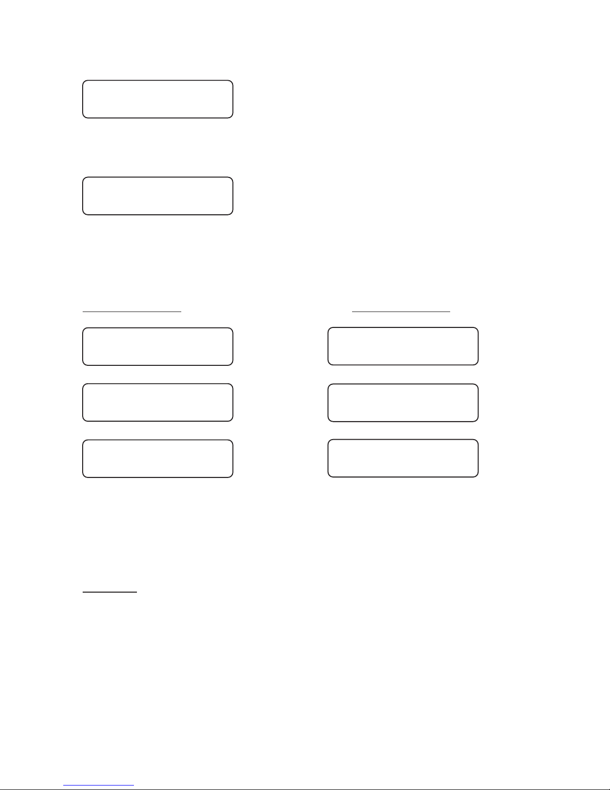
following message:
Switch on a traffic light (which then automatically becomes traffic
light #1). The following must be visible in the traffic light display:
Plug the device into the first traffic light (traffic light #1). Press key #4
on the manual device. The data from the hand device will be transmitted
to the first traffic light (traffic light #1).
Manual device: Control device:
After switching on traffic light #2, the programme is transmitted by
radio or cable to the other traffic light (traffic light #2) and the
installation starts up completely automatically.
Warning: In the event of a data loss at traffic light #1 or #2 (through
activation of the on/off switch), the entire installation must be reprogrammedin the case of a .radio signal installation
Manual Options:
(Flashing, Lights Off, All-Red and Programme Selection)
The procedural methods with manual options can be found in ChapterV
"Auxiliary Functions", on page 53 of this manual.
Put box into
Unit 1 >4<
12,8 V Light ??
No data !
15
12,8 V Light 1
Light 2 missing !
Sending to light
Datablock: 159 /
12,8 V Light 1
Receiving /
Transmission
>> OK <<
Transmission
>> OK <<
1 light correct
programmed
Page 20

4. Input for One-Way Alternating-Direction Traffic
Radio or cable operation with traffic-flow dependency and
with special options such as Nighttime Mode, Day Programme, Interval matrix, Forced Circulation and Data
Transmission via PC
With this manual device you can programme one-way alternatingdirection traffic with traffic-flow dependency and with special
options. Directions for setting the special options can be found
starting on page 49 of this manual.
Before programming the signal equipment, you should make sure that
the time of day and date are set correctly in the manual device. You can
determine this by switching on the manual device. After approximately
10 seconds, the current time of day and date are presented automatically
in the display. If the information shown is not correct, then reset the
numbers as described in the "Auxiliary Functions" Chapter on page 53
of this manual.
Switch further using key #4 until the manual device tells you to
programme the traffic light. In doing so, the manual device requests a
variety of entries.You can alter the date by using the keys #1 and #3. The
number that is currently valid will be flashing.
If you hold the key pressed down for a longer time, then the numbers
change more quickly.
The display shows:
Select with the keys #1 and #3 the desired operating mode, for example
"Cable" or "Radio".
If "Quartz Operation“ is selected, neither traffic flow dependency nor
special options such as Daytime Programme and Time Interval are
Please select:
Quartz Radio Cable
16
**M P B 4400 VA**
One Way Traffic
Page 21

possible. ith key #4 you then move further to the point of entering theW
traffic flow dependency:
Set the traffic-flow dependency to "Yes" ("Yes" flashes) and confirm
the selection with key #4. Pressing key #4 brings you then further to the
point of entering
Here you can alter the length of the roadworks site using the keys #1
and #3.
Once the value is set, proceed further with key #4.
The current speed will be flashing. Set the required speed for within the
roadworks site.
Then press key #4 again. The following will appear:
These two times have been calculated by the manual device.
For safety reasons, the displayed periods for traffic-clearing must be
considered irreducible minimums. It is however possible to increase the
times using key #3--to different extents, if desired: Thus, at a road
works site on a mountain, for example, the ascending traffic can be
allowed a longer traffic-clearing period. Traffic-clearing period #1 ends
when traffic light #2 has finished its "green".
Press key #4 once again and follow the display in the manual device. If
you have selected Daytime Programme as a special option, then the
following display appears. The method used to activate the special
options is described in the annex under "Special Options".
Here you are called upon to enter the 1st Daytime Programme:
Traffic related:
yes no
Site length:
>-< 50 m >+<
Select: (km/h)
10 40 50 7030
Clr.time 1 => 10s
Clr.time 2 = 10s
Input >4<
Dayprogram 1
17
Page 22

Now one can set minimum and maximum green times for signal
group #1. Continue with key #4.
Now the same entries are made as above, this time for signal group #2.
The displayed value in the line in which the arrow is blinking can be
altered using keys #1 and #3. With key #4, one moves one line down,
and can then alter the time setting there.
When you are carrying out a re-programming, you have the opportunity
of deleting old switch points that may be left over from a previous
programming. For this, select "Yes", and confirm your choice with key
#4.
Once you have completed these entries, the manual device will ask you
for 4 switch points for the entered Daytime Programme #1. This means
that once you have entered a Daytime Programme, you can have it start
itself as many as four times a day, at the different times that you select:
00:00 means in this connection no input. For midnight, you must enter
24:00
After entering the starting time, you will be called upon to specify the
days on which the programme is to be used.
If you have selected more than one Daytime Programme, then you will
now be called upon to enter these as described above (Enter Daytime
Programme #2).
After this entry, you have the opportunity of determining the Nighttime
Mode,if you have activated it as described in the annex under "Special
Options”.
Grn1 min => 10s
Grn1 max = 30s
Grn2 min => 10s
Grn2 max = 25s
Switchp. clear ?
yes no
Switchp. 1 Pro 1
Start:>06:00 Uhr
Select Days
all Mo-Fr Sa-So
18
Page 23
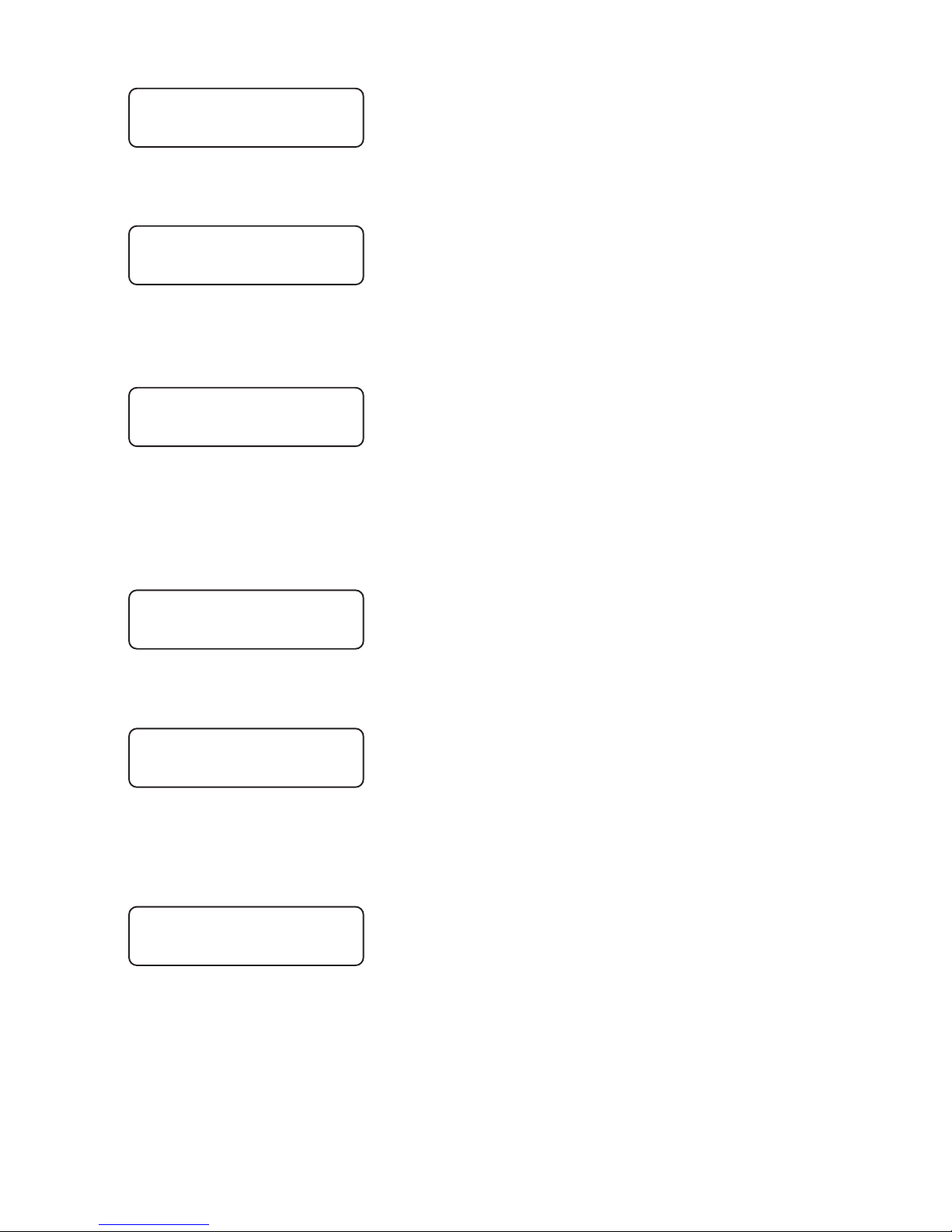
If you select "Yes" here, then you will be called upon to programme the
Night-time Mode:
Here you are asked to select 4 switch points for the Night-time Mode.
This means you can have the Night-time Mode start itself as many as
four times a day, at the different times that you select:
00:00 means in this connection no input. For midnight, you must
therefore enter 24:00
After entering the starting time, you will be called upon to specify the
days on which the programme is to be used.
Afterwards, you have the opportunity to set the Night-time Mode for
Flashing:
Here you are asked to select 4 switch points for the Night-time Mode.
This means you can have the Night-time Mode start itself as many as
four times a day, at the different times that you select:
00:00 means in this connection no input. For midnight, you must
therefore enter 24:00
After entering the starting time, you will be called upon to specify the
days on which the programme is to be used.
Switchp. 1 off
Start:>23:00 Uhr
Nightmode:
yes no
Input >4<
Nightprog. darkl
Select Days
all Mo-Fr Sa-So
Input >4<
Nightprog. flash
Switchp. 1 flash
Start:>22:00 Uhr
19
Page 24

After you have selected the days, (press key #4), the following display
appears, if you have set the Interval Matrix under Special Options to
"Yes":
Using the keys #1 and #3, you can select whether or not you wish to
activate the Interval Matrix. The previous setting flashes. The Interval
Matrix is an additional control function for monitoring the minimum
traffic-clearing periods.
The Interval Time is the period of time between the end of the green
phase (e.g. of traffic light #1) and the beginning of the clear signal
(green) for a coming traffic flow that intersects or merges (in this case
traffic light #2, as one-way alternating-direction traffic operation was
selected). Traffic-clearing time computation proceeds automatically
for one-way alternating-direction traffic.
After selection of the Interval Matrix, the following display appears:
For one-way alternating-direction traffic, the intervals are adopted
automatically from the traffic-clearing times, and can no longer be
altered. This serves for adoption of the minimum traffic-clearing times.
Confirm this with key #>4<. Now the display appears for setting the
interval from traffic light #2 to traffic light #1 (this, too, will be
automatically adopted):
At this point, all the entries in the manual device are completed. Press
key #4 once again. The display shows:
After the formulation of the signal plan, the display switches to the
following message:
Select Days
all Mo-Fr Sa-So
Meantimes
yes no
from 1 => 2
10 sec
from 2 => 1
10 sec
Making
signalplan
20
Page 25
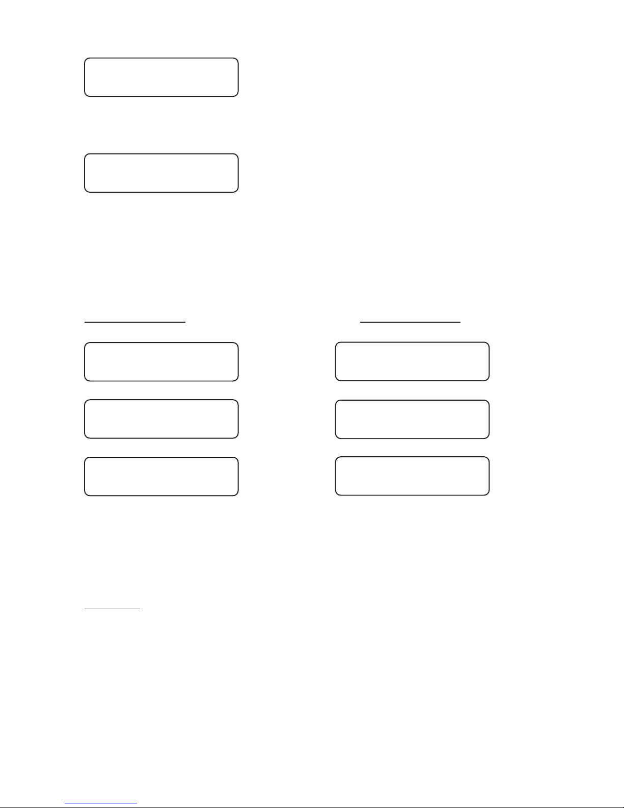
Switch on a traffic light (which then automatically becomes traffic light
#1). The following must be visible in the traffic light display:
Plug the device into the first traffic light (traffic light #1). Press key #4
on the manual device.
The data from the hand device will be transmitted to the first traffic light
(traffic light #1).
Manual device: Control device:
After switching on traffic light #2, the programme is transmitted by
radio or cable to the other traffic light (traffic light #2) and the
installation starts up completely automatically.
Warning: In the event of a data loss at traffic light #1 or #2 (through
activation of the on/off switch), the entire installation must be reprogrammedin the case of a .radio signal installation
Manual Options:
(Flashing, Lights Off, All-Red and Programme Selection)
The procedural methods with manual options can be found in ChapterV
"Auxiliary Functions", on page 53 of this manual.
Put box into
Unit 1 >4<
12,8 V Light ??
No data !
21
12,8 V Light 1
Light 2 missing !
Sending to light
Datablock: 159 /
12,8 V Light 1
Receiving /
Transmission
>> OK <<
Transmission
>> OK <<
1 light correct
programmed
Page 26

5. Input for Junction-Merging and Intersection
Traffic
Without traffic-flow dependency and without special options
With this manual device you can programme junction-merging
and/or intersection traffic for up to 4 groups and 24 signal heads
with cable, and 4 signal heads with radio operation, without trafficflow dependency and without special options.
Before programming the signal equipment, you should make sure that
the time of day and date are set correctly in the manual device. You can
determine this by switching on the manual device.
After approximately 10 seconds, the current time of day and date are
presented automatically in the display. If the information shown is not
correct, then reset the numbers as described in the "Auxiliary
Functions" Chapter on page 53 of this manual. Switch further using key
#4 until the manual device tells you to programme the traffic light. In
doing so, the manual device requests a variety of entries. You can alter
the date by using the keys #1 and #3. The number that is currently valid
will be flashing. If you hold the key pressed down for a longer time, then
the numbers change more quickly.
The display shows:
Select with the keys #1 and #3 the desired operating mode, for example
"Cable" for cable operation.
With key #4 you then move further to the point of entering the total
number of groups:
**M P B 4400**
Cross-roads
Number groups:
One way 3 4
Please select:
Quartz Radio Cable
22
Page 27
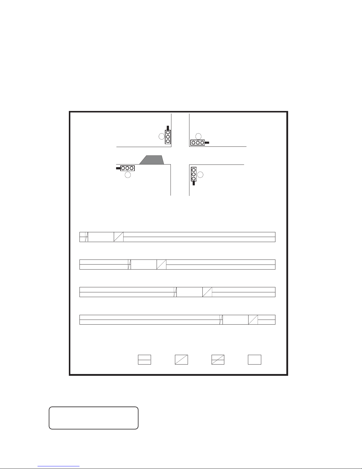
The current total will be flashing. You can now raise or lower the total,
using the keys #1 and #3, e.g. "4" for 4-group operation.
Select for example 4 groups to be entered into the following signal time
plan. Continue using key #4; it is simply the green times "from...to" that
are being entered. The following illustration is offered for
simplification. The installation is linked by wires:
First enter the green time for traffic light #1:
See illustration above... "Light 1”
1.
2.
3.4.
Light 1
543034
41 61 65
66 86 90
95 116 12094
65
40
Light 2
Light 3
Light 4
Legend :
Red Yellow GreenRed/Yellow
0 127
Grn 1 from => 5s
Grn 1 til = 30s
23
Page 28
Here, where the arrow is flashing, one can raise or lower the number of
seconds. In the above illustration, traffic light #1 would show green
from the fifth to the thirtieth second. If one had selected the operating
mode "cable" or "radio" at the start, then one can still enter the number
of signal heads after every "from...to" time entry. A distinction is made
when doing so between roadway and pedestrian signal heads.
A pedestrian signal head stands at double red. You can simply insert a
pedestrian symbol behind the diffusion plate. For entering the total
number of signal heads of the different signal groups, the following
display appears in the manual device:
You can enter the number of the roadway signal heads in the first line:
key #3 for more signal heads, key #1 for fewer. Pressing key #4 brings
you into the second line, where one enters the total of pedestrian signal
heads that functions parallel to the roadway signal heads of group #1.
If you select "Yes" during malfunction flashing, then the entire signal
group shows "Yellow flashing" in the case of a malfunction (pedestrian
signal heads are dark). Should you have altered the pre-setting to "No",
then the entire signal group shows "Dark".
The entries for the groups #2, #3 and #4 are carried out in precisely the
same way.
Continue with key #4.
The manual device presents automatically a circulation time, but this
must be altered to the prescribed value according to the signal time plan.
Then press key #4 again. The display shows:
After creation of the signal plan, the display changes to the following
message:
Shead Gr1> 1
Shead Gr1 0
F. blinking 1 :
yes no
Circ. time=> 127s
Making
signalplan
24
Page 29
Plug the device into traffic light #1. Switch the traffic light on. The
traffic light display shows the following:
Press key #4. The data from the hand device will be transmitted to the
traffic light.The display in the manual device shows the following:
Manual device: Control device:
With radio or cable operation, you only need programme traffic signal
#1 with the manual device. After you have wired the installation, or in
the case of a radio installation, simply switch the other traffic lights on,
one after the other.
The switching-on sequence of the signal heads determines the
relationship to the signal groups with the corresponding number of
signal heads per group. Not until the last signal head is switched on
and the data has been transmitted via radio or cable does the installation
start up automatically through the switching-on programme.
Warning: In the event of a data loss at traffic light #1 or #2 (through
activation of the on/off switch), the entire installation must be reprogrammedin the case of a .radio signal installation
Put box into
Unit 1 >4<
12,8 V Light ??
No data !
25
12,8 V Light 1
Light 2 missing !
Sending to light
Datablock: 159 /
12,8 V Light 1
Receiving /
Transmission
>> OK <<
Transmission
>> OK <<
1 light correct
programmed
Page 30

Manual Options:
(Flashing, Lights Off, All-Red and Programme Selection)
The procedural methods with manual options can be found in ChapterV
"Auxiliary Functions", on page 53 of this manual.
26
Page 31

6. Input for Junction-Merging and Intersection
Traffic
Without traffic-flow dependency, but with special options
such as Night-time Mode, Day Programmes, Interval matrix,
Forced Circulation and Data Transmission via PC
With this manual device you can programme junction-merging
and/or intersection traffic for up to 4 groups and 24 signal heads
with cable, and 4 signal heads with radio operation, without trafficflow dependency but with special options. Directions for setting the
special options can be found starting on page 49 of this manual.
Before programming the signal equipment, you should make sure that
the time of day and date are set correctly in the manual device. You can
determine this by switching on the manual device. After approximately
10 seconds, the current time of day and date are presented automatically
in the display. If the information shown is not correct, then reset the
numbers as described in the "Auxiliary Functions" Chapter on page 50
of this manual.
Switch further using key #4 until the manual device tells you to
programme the traffic light. In doing so, the manual device requests a
variety of entries.You can alter the date by using the keys #1 and #3. The
number that is currently valid will be flashing.
If you hold the key pressed down for a longer time, then the numbers
change more quickly.
The display shows:
Select with the keys #1 and #3 the desired operating mode, for example
"Cable" or "Radio".
**M P B 4400**
Cross-roads
Please select:
Quartz Radio Cable
27
Page 32
With key #4 you then move further to the point of entering the number
of groups:
The current number of groups will be flashing. You can now raise or
lower the total, using the keys #1 and #3, e.g. "4" for 4-group operation.
Press key #4 once again and follow the display on the manual device. If
you have selected as a special option "Daytime Programme", the
following display will appear. The method used to activate the special
options is described in the annex under "Special Options".
Now you are called upon to enter the 1st daytime programme:
First enter the green time for traffic light #1:
(See for this the signal time plan example without daytime programme
on page 23)
Here, where the arrow is flashing, one can raise or lower the number of
seconds. Traffic light #1 would show green in the case presented above
from the second to the seventh second.
If one had selected the operating mode "cable" or "radio" at the start,
then one can still enter the number of signal heads after every
"from...to" time entry. A distinction is made when doing so between
roadway and pedestrian signal heads.
A pedestrian signal head stands at double red. You can simply insert a
pedestrian symbol behind the diffusion plate. For entering the total
number of signal heads of the different signal groups, the following
display appears in the manual device:
You can enter the number of the roadway signal heads in the first line:
key #3 for more signal heads, key #1 for fewer.
Number groups:
One way 3 4
Input >4<
Dayprogram 1
Grn 1 from => 5s
Grn 1 til = 30s
Shead Gr1> 1
Shead Gr1 0
28
Page 33

Pressing key #4 brings you into the second line.
One enters there the total of pedestrian signal heads that functions
parallel to the roadway signal heads of group #1.
If you select "Yes" during malfunction flashing, then the entire signal
group shows "Yellow flashing" in the case of a malfunction (pedestrian
signal heads are dark). Should you have altered the pre-setting to "No",
then the entire signal group shows "Dark".
The entries for the groups #2, #3 and #4 are carried out in precisely the
same way.
Continue with key #4.
The manual device presents automatically a circulation time, but this
must be altered to the prescribed value according to the signal time plan.
Press key #4 to reach the next menu.
When you are carrying out a -programming, you have the opportunityre
of deleting old switch points that may be left over from a previous
programming. For this, select "Yes", and confirm your choice with key
#4.
Here the manual device will ask you for 1-4 switch points for the
entered Daytime Programme #1.
This means that once you have entered a Daytime Programme, you can
have it start itself as many as four times a day, at the different times that
you select:
00:00 means in this connection no input. For midnight, you must enter
24:00.
F. blinking 1 :
yes no
Circ. time=> 127s
Switchp. clear ?
yes no
Switchp. 1 Pro 1
Start:>06:00 Uhr
29
Page 34

After entering the starting time, you will be called upon to specify the
days on which the programme is to be used.
If you have selected more than one Daytime Programme, then you will
now be called upon to enter these as described above (Enter Daytime
Programme #2).
After this entry, you have the opportunity of determiningthe Night-time
Mode, if you have activated it as described in the annex under "Special
Options".
If you select "Yes" here, then you will be called upon to programme the
Night-time Mode:
Here you are asked to select 4 switch points for the Night-time Mode.
This means you can have the Night-time Mode start itself as many as
four times a day, at the different times that you select:
00:00 means in this connection no input. For midnight, you must
therefore enter 24:00
After entering the starting time, you will be called upon to specify the
days on which the programme is to be used.
Afterwards, you have the opportunity to set the Night-time Mode for
Flashing:
Here you are asked to select 4 switch points for the Night-time Mode.
Select Days
all Mo-Fr Sa-So
Nightmode:
yes no
Input >4<
Nightprog. darkl
Switchp. 1 off
Start:>23:00 Uhr
Select Days
all Mo-Fr Sa-So
Input >4<
Nightprog. flash
30
Page 35

This means you can have the Night-time Mode start itself as many as
four times a day, at the different times that you select:
00:00 means in this connection no input. For midnight, you must
therefore enter 24:00.
After entering the starting time, you will be called upon to specify the
days on which the programme is to be used.
After you have selected the days, (press key #4), the following display
appears, if you have set the Interval Matrix under Special Options to
"Yes":
Using the keys #1 and #3, you can select whether or not you wish to
activate the Interval Matrix.
The previous setting flashes. The Interval Matrix is an additional
control function for monitoring the minimum traffic-clearing periods.
The Interval Time is the period of time between the end of the green
phase (e.g. of traffic light #1) and the beginning of the clear signal
(green) for a coming traffic flow that intersects or merges (e.g. traffic
light #2). [Direct interval times (from 1 2, for example) are taken=>
directly from the traffic-clearing time entries and take precedence.
They cannot be altered. Indirect intervals times (from 1 3, for=>
example) must be entered.]
After selection of the Interval Matrix, the following display appears:
(The prescribed time is automatically taken from the traffic-clearing
time and cannot be altered!)
Confirm the prescribed value using key #4.
Now the display appears for setting the interval from traffic light #1
to traffic light #3:
Switchp. 1 flash
Start:>22:00 Uhr
Select Days
all Mo-Fr Sa-So
Meantimes
yes no
from 1 => 2
10 sec
31
Page 36
You must undertake the settings for all interval times as described
above. Once you have finished the entries, press key #4 once again.
The display shows:
After the formulation of the signal plan, the display switches to the
following message:
Plug the device into the traffic light #1. Switch on the traffic light. The
traffic light display shows:
Press key #4. The data from the hand device will be transmitted to the
traffic light.The display in the manual device shows:
Manual device: Control device:
With radio or cable operation, you only need programme traffic signal
#1 with the manual device. After you have wired the installation, br ing
the case of a radio installation, simply switch the other traffic lights on,
one after the other.
from 1 => 3
10 sec
Making
signalplan
Put box into
Unit 1 >4<
12,8 V Light ??
No data !
32
12,8 V Light 1
Light 2 missing !
Sending to light
Datablock: 159 /
12,8 V Light 1
Receiving /
Transmission
>> OK <<
Transmission
>> OK <<
1 light correct
programmed
Page 37

The switching-on sequence of the signal heads determines the
relationship to the signal groups with the corresponding number of
signal heads per group. Not until the last signal head is switched on
and the data has been transmitted via radio or cable does the installation
start up automatically through the switching-on programme.
Warning: In the event of a data loss at traffic light #1 or #2 (through
activation of the on/off switch), the entire installation must be reprogrammedin the case of a .radio signal installation
Manual Options:
(Flashing, Lights Off, All-Red and Programme Selection)
The procedural methods with manual options can be found in ChapterV
"Auxiliary Functions", on page 53 of this manual.
33
Page 38

7. Input for Junction-Merging and Intersection
Traffic
With traffic-flow dependency but without special options
With this manual device you can programme junction-merging
and/or intersection traffic for up to 4 groups and 24 signal heads
with cable, and 4 signal heads with radio operation, with trafficflow dependency but without special options.
Before programming the signal equipment, you should make sure that
the time of day and date are set correctly in the manual device. You can
determine this by switching on the manual device.
After approximately 10 seconds, the current time of day and date are
presented automatically in the display. If the information shown is not
correct, then reset the numbers as described in the "Auxiliary
Functions" Chapter on page 53 of this manual.
Switch further using key #4 until the manual device tells you to
programme the traffic light. In doing so, the manual device requests a
variety of entries. You can alter the date by using the keys #1 and #3.
The number that is currently valid will be flashing.
If you hold the key pressed down for a longer time, then the numbers
change more quickly.
The display shows:
Select with the keys #1 and #3 the desired operating mode, for example
"Cable" or "Radio".
With key #4 you then move further to the point of entering the trafficflow dependency:
* M P B 4400 VA*
Cross-roads
Please select:
Quartz Radio Cable
Traffic related:
yes no
34
Page 39

Using key #1, set the traffic-flow dependency to "Yes" ("Yes" flashes)
and confirm the selection with key #4.
With key #4 you then continue to the point of entering the number of
groups:
The current number of groups will be flashing. You can now raise or
lower the total, using the keys #1 and #3, e.g. "4" for 4-group operation.
Press key #4 once again. The following display will appear:
Here, where the arrow is flashing, alterations can be made. The trafficclearing period #1 can be changed with the keys #1 and #3. The trafficclearing period takes effect when the "green" of the previous traffic
light (4) has ended. Pressing key #4 brings you into the second line.
There one can set the time gap (extension time per message impulse), by
which the green time is extended in connection with a message. As a
rule, one sets a value here of 5 seconds. Continue downwards key #4.
Now one can set the minimum and maximum green times of the signal
group #1. Press key #4.
Normally, the continuous requirement is set at "Yes". That means that
the installation extends the green time for an oncoming vehicle (green
extension mode). If one switches the continuous requirement to "No"
with key #3 ("No" flashes), then the installation functions as a so-called
"All-Red Installation". In such a situation, all the signal heads show allred. The installation goes to green only when prompted. For this
operating mode, the installation must be equipped with radar detectors
with directional recognition. Press key #4.
Clr.time 1 => 6s
Lengthen1= 5s
Grn1 min => 5s
Grn1 max = 10s
continous 1 :
yes no
Extend> Max 1 :
yes no
Number groups:
One way 3 4
35
Page 40
Here you can choose whether an infinite extension of green time is to be
possible. If you select "Yes" (permanent green), then the green time will
be extended until an "opposing" traffic light is prompted by radar
detector. For this it is absolutely mandatory that the green-max.
time #1 be at least 1 second larger than the green-min time for this
group. Continue with key #4.
Here you can set the number of signal heads onsignal group #1. One can
raise or lower the number of signal heads for the roadway signal heads
in the first line, the number of pedestrian signal heads in the second.
Pedestrian and roadway signal heads can also be mixed, so that
pedestrian installations can also be established without any problem.
The maximum total number is 24 signal heads (4 with radio). Continue
with key #4.
If you select "Yes" during malfunction flashing, then the entire signal
group shows "Yellow flashing" in the case of a malfunction (pedestrian
signal heads are dark). Should you have altered the pre-setting to "No",
then the entire signal group shows "Dark". Continue with key #4. Now
you must enter the data for the signal groups #2, #3 and #4 in the same
way.
Shead Gr1> 1
Shead Gr1 0
F. blinking 1 :
yes no
Clr.time 2 => 6s
Lengthen2= 5s
Grn2 min => 5s
Grn2 max = 10s
continous 2 :
yes no
Shead Gr2> 1
Shead Gr2 0
F. blinking 2 :
yes no
36
Page 41
The entries for the signal groups 3 and 4 are carried out analogously, as
described above. Continue with key #4.
After the formulation of the signal plan, the display switches to the
following message:
Plug the device into the traffic light #1. Switch on the traffic light. The
traffic light display shows:
Press# key #4. The data from the hand device will be transmitted to the
traffic light.The display in the manual device shows:
Manual device: Control device:
With radio or cable operation, you only need programme traffic signal
#1 with the manual device. After you have wired the installation, or in
the case of a radio installation, simply switch the other traffic lights on,
one after the other.
Making
signalplan
Put box into
Unit 1 >4<
12,8 V Light ??
No data !
37
12,8 V Light 1
Light 2 missing !
Sending to light
Datablock: 159 /
12,8 V Light 1
Receiving /
Transmission
>> OK <<
Transmission
>> OK <<
1 light correct
programmed
Page 42

The switching-on sequence of the signal heads determines the
relationship to the signal groups with the corresponding number of
signal heads per group. Not until the last signal head is switched on
and the data has been transmitted via radio or cable does the installation
start up automatically through the switching-on programme.
Warning: In the event of a data loss at traffic light #1 or #2 (through
activation of the on/off switch), the entire installation must be reprogrammedin the case of a .radio signal installation
Manual Options:
(Flashing, Lights Off, All-Red and Programme Selection)
The procedural methods with manual options can be found in ChapterV
"Auxiliary Functions", on page 53 of this manual.
38
Page 43

8. Input for Junction-Merging and Intersection
Traffic
With traffic-flow dependency and with special options such
as Night-time Mode, Day Programmes, Interval Matrix,
Forced Circulation and Data Transmission via PC
With this manual device you can programme junction-merging
and/or intersection traffic for up to 4 groups and 24 signal heads
with cable, and 4 signal heads with radio operation, with trafficflow dependency and with special options. Directions for setting the
special options can be found starting on page 49 of this manual.
Before programming the signal equipment, you should make sure that
the time of day and date are set correctly in the manual device. You can
determine this by switching on the manual device.
After approximately 10 seconds, the current time of day and date are
presented automatically in the display. If the information shown is not
correct, then reset the numbers as described in the "Auxiliary
Functions" Chapter on page 53 of this manual. Switch further using key
#4 until the manual device tells you to programme the traffic light. In
doing so, the manual device requests a variety of entries. You can alter
the date by using the keys #1 and #3. The number that is currently valid
will be flashing.
If you hold the key pressed down for a longer time, then the numbers
change more quickly.
The display shows:
Select with the keys #1 and #3 the desired operating mode, for example
"Cable" or "Radio".
* M P B 4400 VA*
Cross-roads
Please select:
Quartz Radio Cable
39
Page 44

With key #4 you then move further to the point of entering the trafficflow dependency:
Using key #1, set the traffic-flow dependency to "Yes" ("Yes" flashes)
and confirm the selection with key #4. With key #4 you then continue to
the point of entering the number of groups:
The current number of groups will be flashing. You can now raise or
lower the total, using the keys #1 and #3, e.g. "4" for 4-group operation.
Press key #4 once again, and follow the display in the manual device. If
you have selected as a special option "Daytime Programme", the
following display will appear. The method used to activate the special
options is described in the annex under "Special Options".
Here, where the arrow is flashing, alterations can be made. The trafficclearing period #1 can be changed with the keys #1 and #3. The trafficclearing period takes effect when the "green" of the previous traffic
light (4) has ended. Pressing key #4 brings you to the next line. There
one can set the time gap (extension time per message impulse), by
which the green time is extended in connection with a message. As a
rule, one sets a value here of 5 seconds.
This entry is carried out for traffic-clearing period + time gap 1, 2, 3
and 4.
Continue downwards with key #4.
Now you will be called upon to enter the 1st daytime programme.
Now one can set the minimum and maximum green times of the signal
Traffic related:
yes no
Number groups:
One way 3 4
Clr.time 1 => 6s
Lengthen1= 5s
Input >4<
Dayprogram 1
Grn1 min => 5s
Grn1 max = 10s
40
Page 45
group #1. Press key #4.
Normally, the continuous requirement is set at "Yes". That means that
the installation extends the green time for an oncoming vehicle (green
extension mode). If one switches the continuous requirement to "No"
with key #3 ("No" flashes), then the installation functions as a so-called
"All-Red Installation". In such a situation, all the signal heads show allred. The installation goes to green only when prompted. For this
operating mode, the installation must be equipped with radar detectors
with directional recognition. Press key #4.
Here you can choose whether an infinite extension of green time is to be
possible. If you select "Yes" (permanent green), then the green time will
be extended until an "opposing" traffic light is prompted by radar
detector. For this it is absolutely mandatory that the green-max.
time #1 be at least 1 second larger than the green-min time for this
group. Continue with key #4.
Here you can set the number of signal heads onsignal group #1. One can
raise or lower the number of signal heads for the roadway signal heads
in the first line, the number of pedestrian signal heads in the second.
Pedestrian and roadway signal heads can also be mixed, so that
pedestrian installations can also be established without any problem.
The maximum total number is 24 signal heads (4 with radio). Continue
with key #4.
If you select "Yes" during malfunction flashing, hen the entire signalt
group shows "Yellow flashing" in the case of a malfunction (pedestrian
signal heads are dark). Should you have altered the pre-setting to "No",
then the entire signal group shows "Dark". The entries for the other
continous 1 :
yes no
Extend> Max 1 :
yes no
Shead Gr1> 1
Shead Gr1 0
F. blinking 1 :
yes no
41
Page 46

groups proceeds analogously. Use key #4 to proceed to the next menu.
When you are carrying out a -programming, you have the opportunityre
of deleting old switch points that may be left over from a previous
programming. For this, select "Yes", and confirm your choice with
key #4.
Here the manual device will ask you for 1-4 switch points for the
entered Daytime Programme #1.
This means that once you have entered a Daytime Programme, you can
have it start itself as many as four times a day, at the different times that
you select:
00:00 means in this connection no input. For midnight, you must enter
24:00
After entering the starting time, you will be called upon to specify the
days on which the programme is to be used.
If you have selected more than one Daytime Programme, then you will
now be called upon to enter these as described above (Enter Daytime
Programme #2).
After this entry, you have the opportunity of determiningthe Night-time
Mode, if you have activated it as described in the annex under "Special
Options":
If you select "Yes" here, then you will be called upon to programme the
Night-time Mode:
Switchp. clear ?
yes no
Switchp. 1 Pro 1
Start:>06:00 Uhr
Select Days
all Mo-Fr Sa-So
Nightmode:
yes no
Input >4<
Nightprog. darkl
42
Page 47

Here you are asked to select 4 switch points for the Night-time Mode.
This means you can have the Night-time Mode start itself as many as
four times a day, at the different times that you select:
00:00 means in this connection no input. For midnight, you must
therefore enter 24:00
After entering the starting time, you will be called upon to specify the
days on which the programme is to be used.
Afterwards, you have the opportunity to set the Night-time Mod for
Flashing:
Here you are asked to select 4 switch points for the Night-time Mode
(Flashing). This means you can have the Night-time Mode start itself as
many as four times a day, at the different times that you select:
00:00 means in this connection no input. For midnight, you must
therefore enter 24:00
After entering the starting time, you will be called upon to specify the
days on which the programme is to be used.
After you have selected the days, (press key #4), the following display
appears, if you have set the Interval Matrix under Special Options to
"Yes":
Using the keys #1 and #3, you can select whether or not you wish to
activate the Interval Matrix. The previous setting flashes. The Interval
Switchp. 1 off
Start:>23:00 Uhr
Select Days
all Mo-Fr Sa-So
Input >4<
Nightprog. flash
Switchp. 1 flash
Start:>22:00 Uhr
Select Days
all Mo-Fr Sa-So
Meantimes
yes no
43
Page 48

Matrix is an additional control function for monitoring the minimum
traffic-clearing periods.
The Interval Time is the period of time between the end of the green
phase (e.g. of traffic light #1) and the beginning of the clear signal
(green) for a coming traffic flow that intersects or merges (e.g. traffic
light #2). [Direct interval times (from 1 2, for example) are taken=>
directly from the traffic-clearing time entries and take precedence.
They cannot be altered. Indirect intervals times (from 1 3, for=>
example) must be entered.]
After selection of the Interval Matrix, the following display appears:
The prescribed time is automatically taken from the traffic-clearing
time and cannot be altered!
Confirm the prescribed value using key #4. Now the display appears for
setting the interval from traffic light #1 to traffic light #3:
You must undertake the settings for all interval times as described
above. Once you have finished the entries, press key #4 once again.
The display shows:
After the formulation of the signal plan, the display switches to the
following message:
Plug the device into the traffic light #1. Switch on the traffic light. The
traffic light display shows:
Press key #4.
from 1 => 2
10 sec
from 1 => 3
10 sec
Making
signalplan
Put box into
Unit 1 >4<
12,8 V Light ??
No data !
44
Page 49
The data from the hand device will be transmitted to the traffic light.
The display in the manual device shows:
Manual device: Control device:
With radio or cable operation, you only need programme traffic signal
#1 with the manual device. After you have wired the installation, or in
the case of a radio installation, simply switch the other traffic lights on,
one after the other.
The switching-on sequence of the signal heads determines the
relationship to the signal groups with the corresponding number of
signal heads per group. Not until the last signal head is switched on
and the data has been transmitted via radio or cable does the installation
start up automatically through the switching-on programme.
Warning: In the event of a data loss at traffic light #1 or #2 (through
activation of the on/off switch), the entire installation must be reprogrammedin the case of a .radio signal installation
Manual Options:
(Flashing, Lights Off, All-Red and Programme Selection)
The procedural methods with manual options can be found in ChapterV
"Auxiliary Functions", on page 53 of this manual.
45
12,8 V Light 1
Light 2 missing !
Sending to light
Datablock: 159 /
12,8 V Light 1
Receiving /
Transmission
>> OK <<
Transmission
>> OK <<
1 light correct
programmed
Page 50

9. Reprogramming or changing time settings in radio /
cable signalling equipment that has already been put
into operation.
With the new software version of our traffic signal systemMPB 4400
you can carry out modifications to the radio/cable signalling equipment
without having to switch off the signal system first. The signal system
switches automatically to "all-red" during reprogramming and, after
reprogramming is completed, switchesautomatically back to automatic
operation.
Follow this procedure:
Use the manual programming device to correct/modify the required
times or other data for your construction measures.Apart from the basic
entries, such as:
- Number of groups,
- Number and type of signal heads (motor
vehicle/pedestrian),
- Mode of operation radio/cable,
all information and data can be modified. When all entries are
completed, the manual programming device shows the following
display (already seen in previous programming):
Once the signal plan has been created, the display changes to the
following:
or
Now plug the manual programming device into operating traffic light
1 traffic light 1K1or (if traffic light 1 is operating with more than one
signal head).
Press key 4 on the manual programming device.
Making
signalplan
Put box into
Unit 1 >4<
Put box into
Unit 1K1 >4<
46
Page 51
The data from the manual programming device is then transferred to the
operating signal system (during data transfer, the signal system
switches automatically to all-red).
Manual device: Control unit:
After the data has been transferred from the manual programming
device to traffic lights 1 or 1K1 and then from traffic lights 1 or 1K1 to
all other traffic lights, the signal systemautomatically starts up again.
12,8 V Light 1
Light 2 missing !
Sending to light
waiting for red
Sending to light
Datablock: 159 /
12,8 V Light 1
Receiving /
12,8 V Light 1
sending data /
Transmission
>> OK <<
Transmission
>> OK <<
Transmission
>> OK <<
1 light correct
programmed
Handbox off
with key >4<
47
Page 52

10. Reading out data with the handbox while the traffic
light is operating
The current software version in the handbox and in the light system
MPB 4400 now gives you the possibility of reading out the existing
program from traffic light 1 or 1K1 to the handbox. In this way, you can
make changes to the current program of the radio or cable traffic signal,
or prepare the data for another traffic light system.
To do so, switch the handbox on. Use button 2 to move up in the menu
until this appears
Now please go to light 1 or 1K1 and place the handbox in the control
unit. Press button 3 to read the traffic light data from on-going operation
and save these in the handbox. Now you can edit the data as explained
above and send the possibly changed data back to the traffic signal, or
use them to program another traffic light.
Receive data
from light >3<
48
Page 53

III. Special Options with Quartz Operation
In order to reach the Menu items with special options, press key #2
several times after switching on the manual device.
Night-time Mode
Before putting the night-time mode function into operation, you should
make sure that the time of day and date are set correctly in the manual
device.You can determine this by switching on the manual device.
After approximately 10 seconds, the current time of day and date are
presented automatically in the display.
If the information shown is not correct, then reset the numbers as
described in the "Auxiliary Functions" Chapter of this manual. Switch
the manual device on. Press key #2 several times, until the following
display appears:
You can activate the night-time mode at this point in the display. You
can move back and forth in the familiar way using keys #1 and #3. Once
the night-time mode has been activated, the input prompt for the nighttime mode will appear in the course of the programming. You then
proceed as described in the course of the directions for operation.
Nightmode:
yes no
49
Page 54

IV. Special Options with Radio or Cable
Operation
In order to reach the Menu items with special options, press key #2
several times after switching on the manual device.
Night-time Mode
Before putting the night-time mode function into operation, you should
make sure that the time of day and date are set correctly in the manual
device.You can determine this by switching on the manual device.
After approximately 10 seconds, the current time of day and date are
presented automatically in the display.
If the information shown is not correct, then reset the numbers as
described in the "Auxiliary Functions" Chapter of this manual. Switch
the manual device on. Press key #2 several times, until the following
display appears:
You can activate the night-time mode at this point in the display. You
can move back and forth in the familiar way using keys #1 and #3. Once
the night-time mode has been activated, the input prompt for the nighttime mode will appear in the course of the programming. You then
proceed as described in the course of the directions for operation.
Nightmode:
yes no
50
Page 55

Daytime Programme
Neither the use nor the activation of daytime programmes is possible
with quartz operation.
Before setting the daytime programme, you should make sure that the
time of day and date are set correctly in the manual device. You can
determine this by switching on the manual device. After approximately
10 seconds, the current time of day and date are presented automatically
in the display.
If the information shown is not correct, then reset the numbers as
described in the "Auxiliary Functions" Chapter starting on page 53 of
this manual. Switch the manual device on. Press key #2 several times,
until the following display appears:
The pre-set value is flashing. Using the keys #1 and #3, you can select
up to 4 daytime programmes. After you have selected the number of
daytime programmes, continue to programme the installation as
described in the course of the directions for operation.
Interval Matrix
The interval matrix is an auxiliary control function for monitoring the
minimum traffic-clearing periods. The interval is the amount of time
between the end of the green phase (e.g. of traffic light #1) and the start
of the clear signal (green) for a subsequent intersecting or merging
traffic flow (e.g. traffic light #2).
You have the opportunity of activating the interval matrix:
The pre-set value is flashing. You can select the setting using the keys
#1 and #3.
Dayprograms:
1 2 3 4
Meantimes
yes no
51
Page 56

Forced Circulation
Forced circulation serves the purpose of putting an emergency
circulation into effect in cases of failure of radar movement detectors or
pedestrian request buttons. Forced circulation is useful only in
conjunction with a traffic-dependency-operated All-Red installation or
installations that operate with green-on-demand features for side
streets, for example. As an experiment, enter "Yes" in the Menu
"Traffic-dept." using key #1 ("Yes" flashes). Then go back using key #2
until the following Menu appears:
You can alter the value here with the keys #1 and #3 where the arrow is
flashing. You go up one line using key #2. There you can switch to "Yes"
using key #1 and "No" using key #3. The forced circulation is thus
activated or not after each of the times set. This entry window will
continue to be present until the setting for traffic dependency is
switched back to "No".
Expect Data from PC...
With this function, the opportunity exists of entering data from a PC via
interface. This option is explained in extra operating instructions for PC
programming
To exit the special options menu items, press key #4 several times.
This will then take you back to the programming procedures
described in this operating manual.
Fail-safe: yes
every> 5 minutes
52
Page 57

V. Auxiliary Functions
1. Manual Options with One-Way Alternating-Direction
Traffic:
(Manual Operation, Flashing, Lights Off, All-Red and Programme
Selection)
Manual operation is possible only with either radio or cable operation.
Simply plug the manual device into an installation that is in operation.
After that, switch the manual device on using the key "ON".
The display now shows:
Hand operation => <=Flashing=> <=Lights Off=> <=All-Red=>
<=Programme Selection=> <=Manual Device Off
Select the operating mode using the keys #1 and #3. The traffic light
installation is switched over to the selected operating mode with key #4.
When >Manual Mode< is selected, the following display appears:
The traffic light installation now runs to the next possible automatically
pre-set green waiting point and stops there.
The display shows:
Now press key #3, so that the traffic light installation runs to the next
automatically pre-set green waiting point. It is not possible to use this to
shorten the traffic-clearing period (interval). If you wish to exit manual
operation, then press key #4.
If you wish a different operating mode, for example "Flashing", "Lights
Off", "All-Red" or "Programme Selection", then you can switch over to
the desired operating mode using the menu item "Please Select:"
(before doing this, switch the manual device off and then on again).
Press for example key #3 in order to switch over to "Flashing". You
switch on the selected operating mode by pressing key #4.
Please select:
Manual ==>
with key 3 --->
with key 1 <---
Please wait...
Green 1 is coming
3=Go on 4=End
> Green1 there<
53
Page 58

The manual device display shows:
The installation runs automatically to the switch point set internally and
switches then to "Flashing".
The manual device now shows:
Remove the manual device from the control unit and switch it off as
shown by twice pressing key #4.
If you would like to switch back to "Automatic", then proceed as
follows: plug the manual device into one of the control devices (it
doesn’t matter which one). switch the manual device on.Then
The manual device then displays the current operating mode of the
installation in operation. In this example: "Flashing”
Switch back with key #4 to automatic mode. Afterwards you will be
called upon to switch the manual device off.
Entering programme selection proceeds as follows: plug the manual
device into . , switch the manual device ontraffic light #1 After that
using the key "ON". Select the operating mode using keys #1 and #3.
The traffic light installation switches over using key #4 to the selected
operating mode. The display now shows:
Please select:
Pro 1
Pro 2
Pro 3
Pro 4
Pro 7 (Off)
Pro 8 (Flashing)
Please wait...
>Flashing coming
>Flashing there
Automatic >4<
Please select:
>-< Pro 1 >+<
54
>Flashing there
Automatic >4<
Page 59

Programme Selection can be carried out only at traffic light #1.
After selecting the programme, press key #4:
Non-programmed programmes cannot be selected. Remove the manual
device from the control unit and switch it off as shown by twice pressing
key #4.
If you would like to switch back to "Clock Mode", then proceed as
follows: plug the manual device into one of the control devices (it
doesn’t matter which one). switch the manual device on.Then
The manual device then displays the current operating mode of the
installation in operation. In this example: "Pro 1”
Switch over to clock mode using key #4.
2. Manual Options with Intersecting Traffic:
(Manual Operation, Flashing, Lights Off, All-Red and Programme
Selection)
Manual operation is possible only with either radio or cable operation.
Simply plug the manual device into an installation that is in operation.
After that, switch the manual device on using the key "ON".
The display now shows:
Hand operation => <=Flashing=> <=Lights Off=> <=All-Red=>
<=Programme Selection=> <=Manual Device Off
Select the operating mode using the keys #1 and #3. The traffic light
installation is switched over to the selected operating mode with key #4.
When >Manual Mode< is selected, the following display appears:
The traffic light installation now runs to the next possible automatically
Please wait...
>Pro 1 coming
> Pro 1 < there
Clockmode: >4<
Please wait...
--> Waitingpoint
55
Please select:
Manual ==>
with key 3 --->
with key 1 <---
Page 60

pre-set green waiting point and stops there.
The display shows:
Now press key #3, so that the traffic light installation runs to the next
automatically pre-set green waiting point. It is not possible to use this to
shorten the traffic-clearing period (interval). If you wish to exit manual
operation, then press key #4.
If you wish a different operating mode, for example "Flashing", "Lights
Off", "All-Red" or "Programme Selection", then you can switch over to
the desired operating mode using the menu item "Please Select:"
(before doing this, switch the manual device off and then on again).
Press for example key #3 in order to switch over to "Flashing". You
switch on the selected operating mode by pressing key #4.
The manual device display shows:
The installation runs automatically to the switch point set internally and
switches then to "Flashing".
The manual device now shows:
Remove the manual device from the control unit and switch it off as
shown by twice pressing key #4.
If you would like to switch back to "Automatic", then proceed as
follows: plug the manual device into one of the control devices (it
doesn’t matter which one). switch the manual device on.Then
The manual device then displays the current operating mode of the
installation in operation. In this example: "Flashing”
Switch back with key #4 to automatic mode. Afterwards ou will bey
called upon to switch the manual device off.
56
3=Go on 4=End
>Waitingpoint<
Please wait...
>Flashing coming
>Flashing there
Automatic >4<
>Flashing there
Automatic >4<
Page 61

Simply plug the manual device into an installation that is in operation.
After that, switch the manual device on using the key "ON".
The display now shows:
Please select:
Pro 1
Pro 2
Pro 3
Pro 4
Pro 7 (Off)
Pro 8 (Flashing)
Programme Selection can be carried out only at traffic light #1.
After selecting the programme, press key #4:
Non-programmed programmes cannot be selected.
Remove the manual device from the control unit and switch it off as
shown by twice pressing key #4.
If you would like to switch back to "Clock Mode", then proceed as
follows: plug the manual device into one of the control devices (it
doesn’t matter which one). switch the manual device on.Then
The manual device then displays the current operating mode of the
installation in operation. In this example: "Pro 1”
Switch over to clock mode using key #4.
57
Please select:
>-< Pro 1 >+<
Please wait...
>Pro 1 coming
> Pro 1 < there
Clockmode: >4<
Page 62

3. Setting Date and Time
Change in the handbox:
First switch the handbox off. Then press and hold button 1 and switch
the handbox on (press "On" briefly).
Release button 1 after approx. 10 seconds. Use buttons 1 and 3 to
increase and decrease the value marked with "> <". Use button 4 to
move on to adjust the next value. If you press button 4 again after
adjusting the value for seconds, this resets the internal clock to the
previously adjusted values.
Note: it is important for the clock to be adjusted correctly if the data of a
traffic signal are to be printed out or if the daytime programs or nighttime operation are activated. This ensures that the reports are produced
with the correct date and right time. The daytime programs and nighttime operation are thus also switched on automatically at the right time.
Change in the signal system:
Please first adjust the current time in the handbox as described above.
To update this time now in the traffic signal without reprogramming –
e.g. when changing over from summer time to winter time – switch the
handbox on and use button 2 to select the following menu point:
Now place the handbox in light 1 or 1K1. Press button 3 to transfer just
the date and time from the handbox to the control unit. All other
program settings in the light remain unchanged.
Press button 2 repeatedly to switch the handbox off.
58
Light clock 1
(1H1) set >3<
Page 63

*PeterBerghaus*
* Traffic Light *
Vers. H1010 08:40
Handbox: 685
4. Version Display in Manual Device
First switch the manual device off. Switch the manual device on, using
the key "On"; the following message appears in the display:
The installed software version appears then in the first line and the serial
number of the manual device in the second.
59
Page 64

5.Acknowledging errors
If the manual device is plugged into a flashing installation and then
switched on, as though one wished to operate the installation manually,
and the above message appears, then the installation had an error (for
example, green-green violation).
In such cases, the message in the traffic light display is to be followed.
That is where the error is more precisely described. An attempt can be
made to acknowledge the error using key #4.
Should the installation still not start up after that, then the corresponding error must be eliminated.
Quit Failure
with key >4< !
60
Page 65
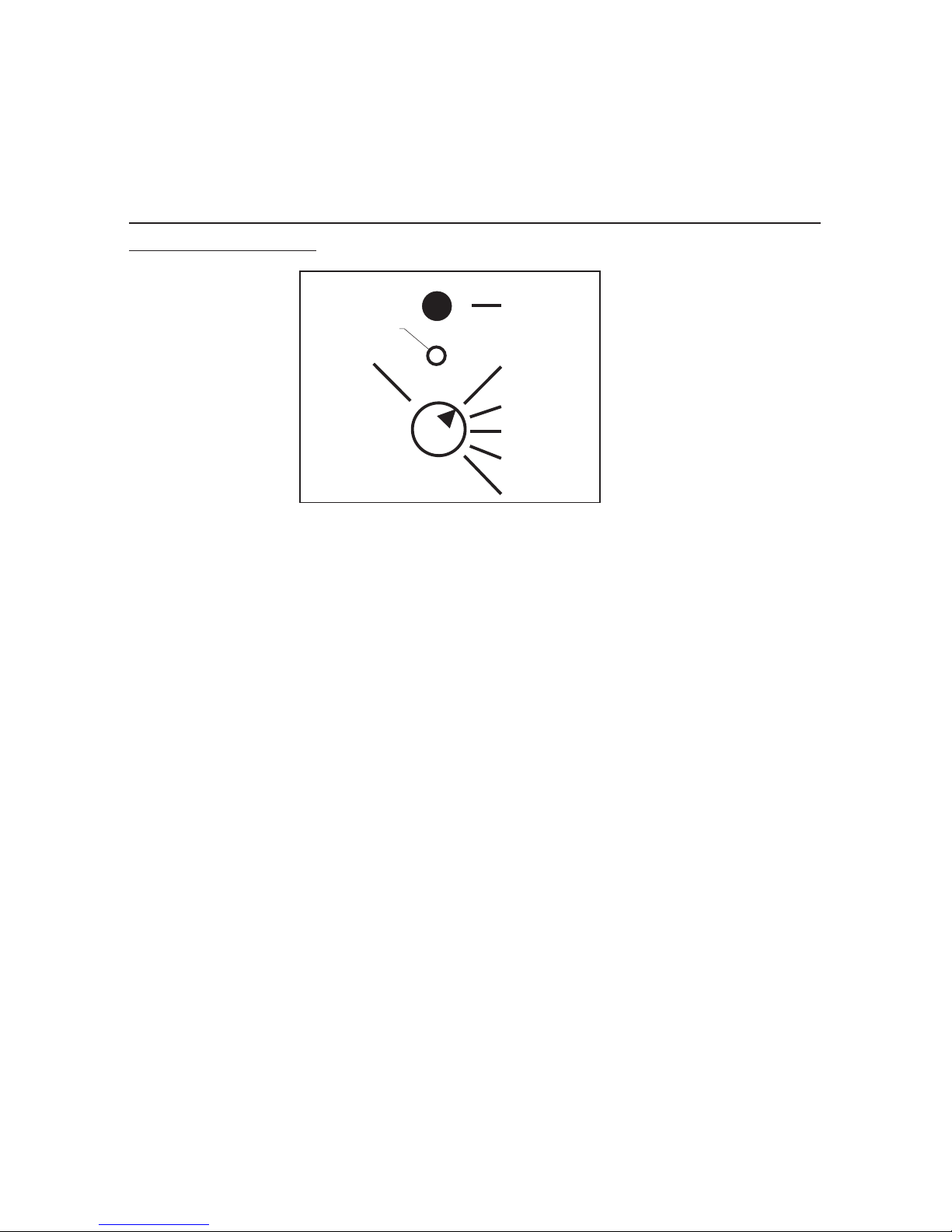
6. Special Operation modes using internal and external rotary
switches for manual options, such as manual operation, flashing,
lights off and all-red
6.1. Setting special operating modes by means of built-in rotary
switches (optional)
For example: manual operation (only possible with cable and radio
control)
Set the rotary switch to manual operation; after approximately
5 seconds the red LED flashes. This means that the special operating
mode you selected has been activated. If the red LED changes from
flashing red to a continuous red light, the signal system is in the next
possible green waiting point. By pressing the key, the signal system
moves to the next green waiting point of the following signal group.
When the key is pressed, the LED flashes red; when the next green
waiting point is reached, the LED is again a continuous red light. It is
therefore not possible to use this to shorten the traffic-clearing period
(time interval). The sequence and current status of the individual signal
groups can be observed on the traffic light display.
If you wish to exit manual operation, turn the rotary switch from manual
operation back to automatic. The red LED switches itself off after
approximately 5 seconds showing that the signal system has switched
itself back to automatic operation.
If you wish to have further special operating modes, such as flashing,
lights off and all-red, follow this procedure:
Turn the rotary switch from automatic to the desired special operating
mode, e.g. flashing.After approximately 5 seconds, the red LED flashes
PUSH BUTTON
AUTOMATIC
MANUAL
CONTROL
FLASHING
LAMPS OFF
ALLRED
EXTERN
Function LED
61
Page 66

indicating that the special operating mode you selected has been
activated. The signal system now operates until the preset switch-off
time and then switches via a switch-off display to yellow flashing.
(Please note that the only motor vehicle groups that flash are those that
have been programmed with "yes" in the "Error flashing" menu item;
pedestrian signal heads automatically have a dark display.) The LED
lights up continuously when the selected special operating mode has
been reached.
If you wish to exit the selected special operating mode (yellow
flashing), turn the rotary switch back to automatic. The red LED turns
itself off after approximately 5 seconds and the signal system
automatically switches back to automatic operation via an activation
program.
6.2. Setting special operating modes by means of external cable remote
control (optional)
1. Set the rotary switch of the (optional) built-in manual control
to the position “extern”.
2. Choose the desired special operation mode by means of the
rotary-switch on the external cable remote control.
3. Open the cap of the connector for the external cable remote
control below the control chamber of the traffic light.
4. Connect the plug of the cable remote control to the connector
of the traffic light and fasten it by turning around the nut of the
plug.
5. After approx. 5 seconds the chosen special operation mode
would be activated. The further steps for choosing the different
special operation modes you could find in chapter 6.1 on the
pages before.
62
Page 67
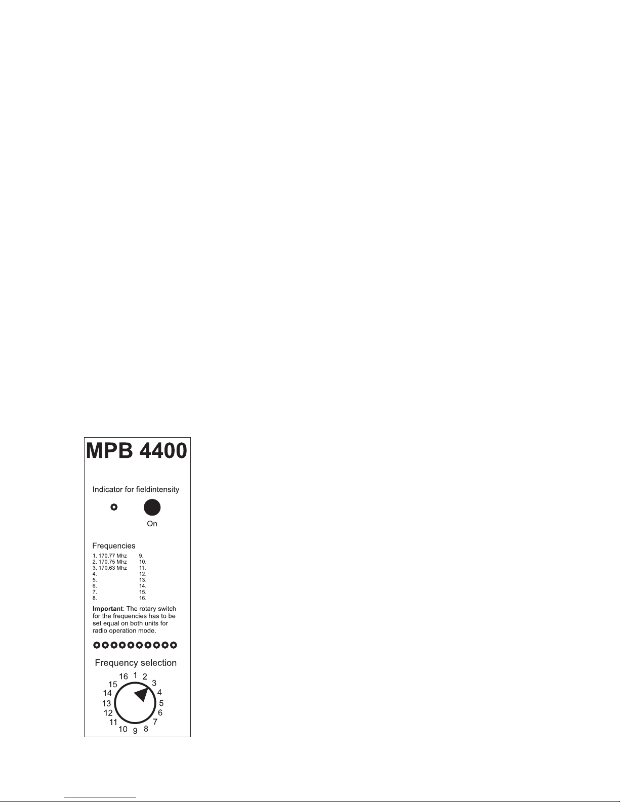
Common comments
If several signal heads are modified with this accessory equipment, you
have to be sure that the use would be made only at one signal head. On
all other signal heads the rotary-switches have to stay in position “Automatic”. Should one rotary-switch unnoticed not stay on “Automatic”position, the red function-LED will show a fast blinking indication.
This means a malfunction and the traffic light could not execute the
chosen mode. Please, check which rotary-switch is not in the “Automatic”-position and bring him into the right position(Automatic). Now,
after approx. 5 seconds, the chosen special operation mode would be
activated.
Attention: It is not possible to choose the special operation mode
“Flashing” and “Lamps Off” directly while staying in the special
operation modes “Manual operation” or “Allred”. Hereby it is
necessary to choose first the special operation mode “Automatic” and
afterwards the desired special operation mode (Flashing or Lamps Off).
Adirect change between theother special operation modes is possible.
7. Multi-frequency technology with field strength display (optional)
As an option, the MPB 4400 can be equipped with the
very latest multi-frequency technology. In addition
to the internally fitted special radio module, the
frequency selection switch and detailed field
strength display are integrated in the front panel.
Altogether 10 coloured LEDs clearly show the
reception field strength of the other traffic light.
However, this depends on all control units being set
to the same frequency (1 to 16). The quality of the
radio connection is clearly indicated from red
(inadequate) via yellow (adequate) to green for
outstanding transmission. By taking account of the
field strength display already before connecting up
the other signal heads, this signal display can also be
used to select a radio frequency with the lowest
possible use in order to obtain a free channel.
63
Page 68

The display lighting and field strength display is switched on by
pressing the button "Field strength display and LCD lighting".
During on-going operation, this display can also be used to optimize the
position of the signal heads, as even the tiniest shift in position of often
just a few centimetres can clearly improve or naturally also deteriorate
the reception. With the detailed field strength display, you can now find
the best position for using the signal heads in radio operation – so say
goodbye to the dead spots!
Thanks to the multi-frequency feature, consisting of the special radio
module, frequency selection switch and field strength display, in
Germany it is possible to choose between four frequencies currently
licensed in the 2mband for use by radio traffic lights. This choice can be
extended to up to 16 frequencies for exports.
This means naturally that we can supply other frequencies or frequency
ranges (e.g. 70 cm UHF) with many different transmitter output ratings
for use outside Germany.
64
Page 69
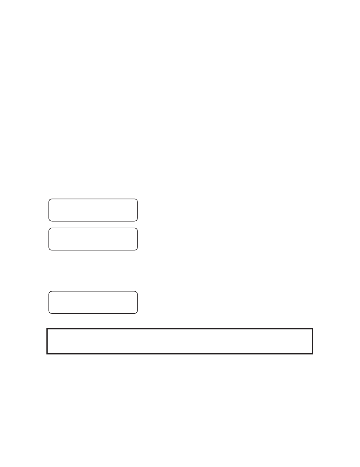
VI. Control Device
VI.1 Switching Control Device On and Off- Changing
the Storage Batteries
The control device is equipped with only an On/Off switch and a fuse.
The maximum allowed value of the fuse is 6.3 A!
In order to put the installation into operation, the first thing is to clamp
on the storage battery in the battery box (being careful to ensure correct
polarity!) Switch on the traffic light using the main switch. The traffic
light display will now automatically show the manufacturer and the
EPROM version:
After this automatically-appearing message, the display should show
the following:
The control unit can be re-programmed only in conjunction with the
display "Expect Data"!
After successful programming, the signal head sends a message with
the respective traffic light number.
*PeterBerghaus*
* Traffic Light *
Epromversion:
H1010 08:40
12,8 V Light ??
No data !
65
Page 70
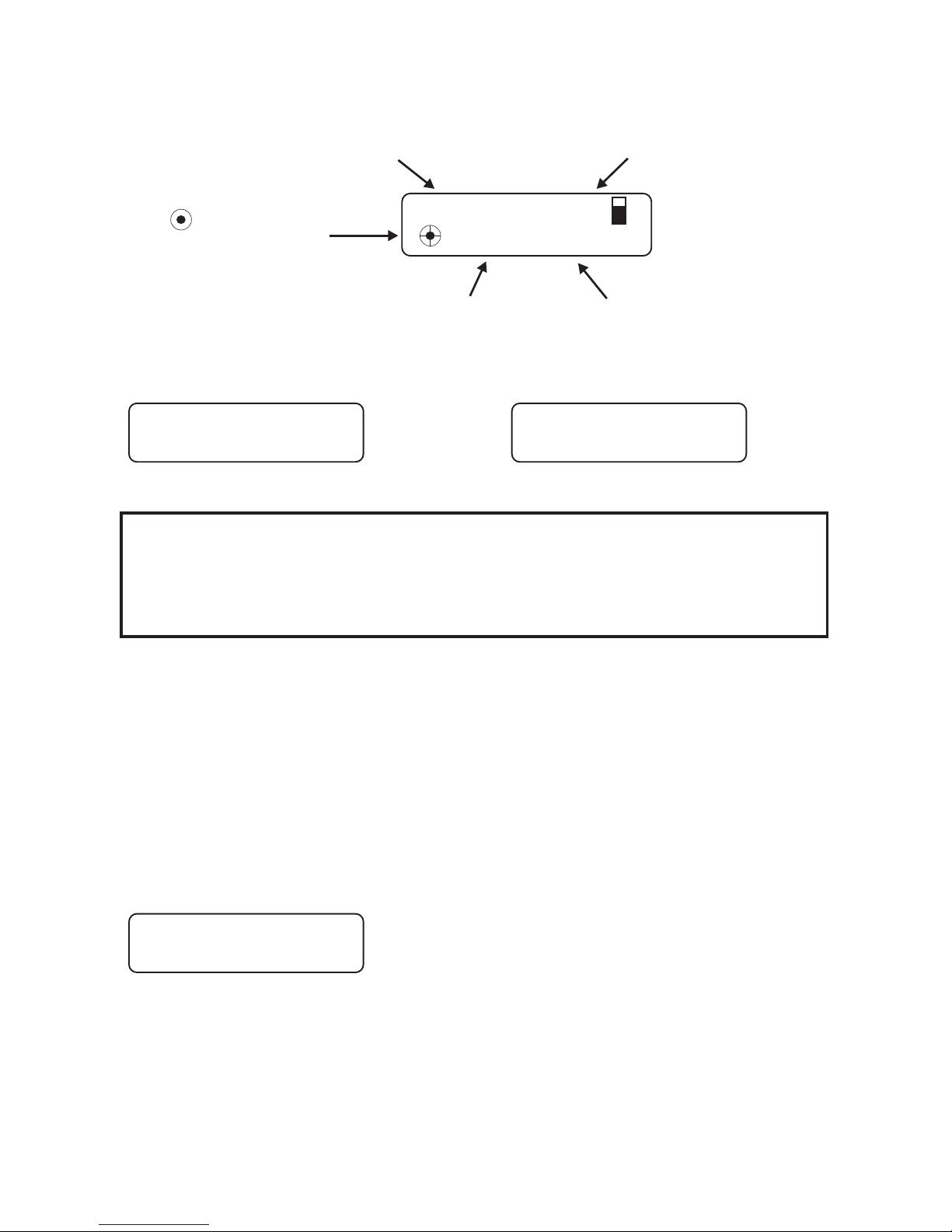
The display appears as follows:
Should the installation be malfunctioning, then a clear description of
the error will be displayed in the second line.
or
Warning:
If the installation is switched off for 10 seconds or more, then all data
will be lost!The traffic light will then have to be re-programmed.
All data are retained while changing storage batteries.
Should the storage battery voltage fall below ca. 11 Volts during operation, a corresponding warning will appear in the display of the control
device, when it is set for quartz operation.
Should the equipment be linked by either wiring or radio, then one can
see at every signal head where the storage batteries need to be changed
(see also at Error Description).
The following message appears:
12,8 V Light 1
10s Red
Voltage or programme or time of day Traffic light number and signal configuration
light statuscirculation second
only with traffic actuated operation
+ = message
= demand stored in memory
12,8 V Light 1
Light 2 missing !
12,8 V Light 1K1
Light 1K2 missing !
*Accu change !*
10 V
66
Page 71
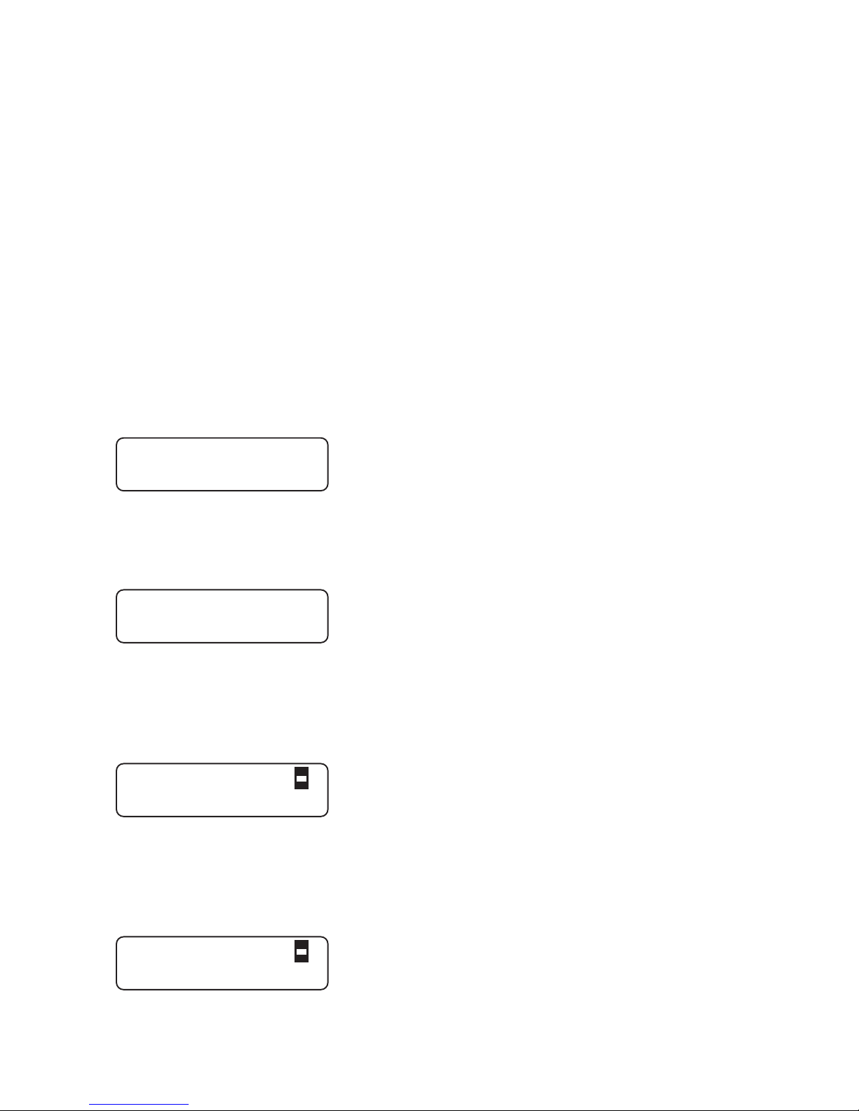
VI.2 Error Messages for Control Device
The error messages of the control device are displayed in the lower line
of the LED display. The error display is very user-friendly. All
currently-active errors are displayed, one after the other, using clear
designations in slow succession to one another.
In the cases of cable and radio installations, not just the errors of the
individual equipment are displayed, but also those present at other
traffic lights. When you are summoned to a malfunctioning installation,
open at random a control device cover. There you will see for example
in the display "Red 2 defective".
The displayed text speaks for itself. Proceed to traffic light #2 and
overhaul the red light.
The installation will then return by itself to programme flow.
An attempt has been made to programme a new control device with an
old manual device, or vice-versa (different EPROM versions).
Remedy: contact us and request the current version number.
The control device has a malfunction.
Switch the control unit off and then on again. Normally, this should
remove the malfunction. If this is not the case, please send the control
card to the factory for repair.
The red lamp at traffic light #2 is defective and must be replaced. After
elimination of the error, the installation starts up again automatically. If
the traffic light is fitted with LED-modules you have to quitt the failure
as described on page 60.
This is a status error. Yellow or red status errors can also occur. In this
WRONG VERSION !
*INTERNAL FAILURE
12,8 V Light 1
Red defect 2
12,8 V Light 1
Green status 3
67
Page 72
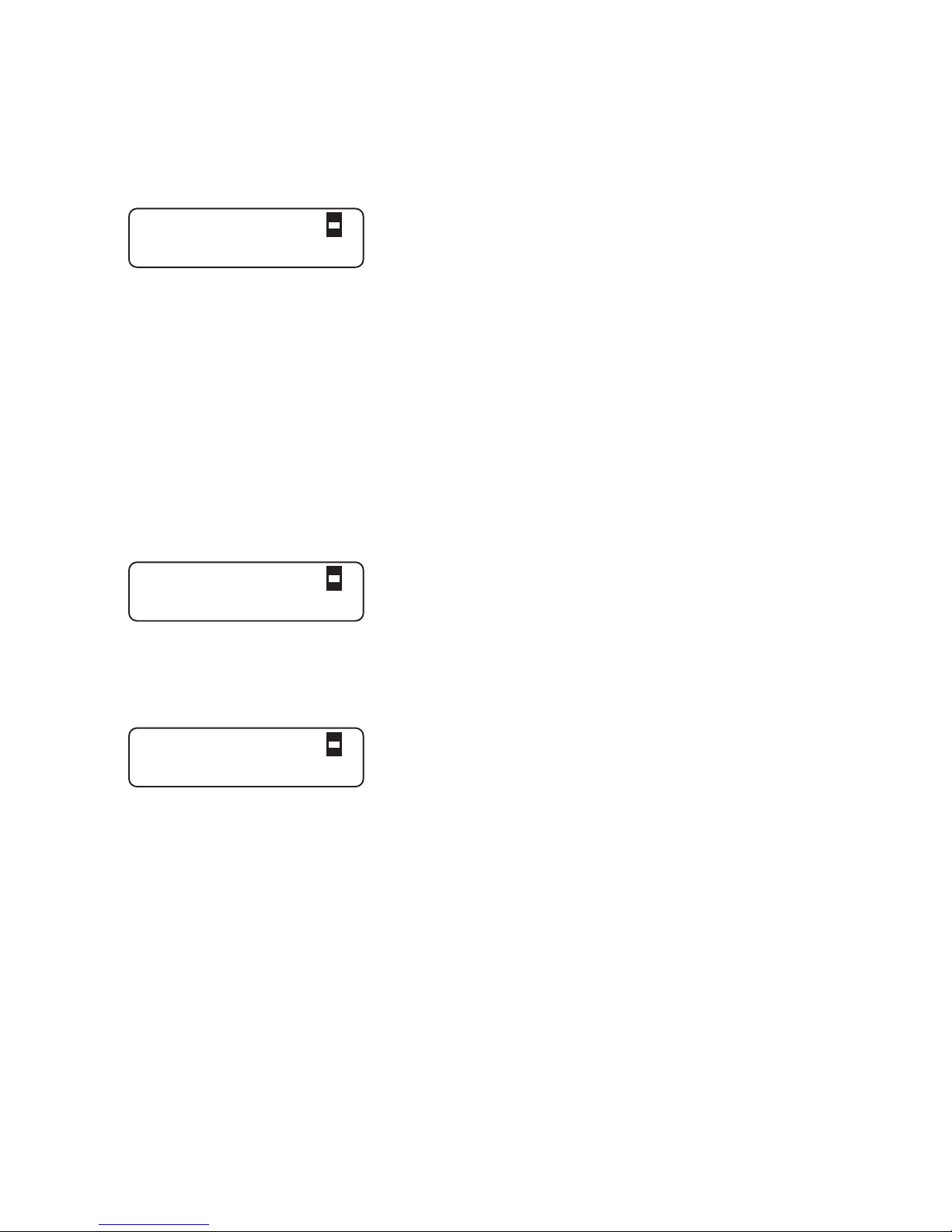
case of this error, the directive to the control does not conform to the
actual task at hand. Acknowledge the error using the manual device.
Should the error re-occur, then you must send the control panel to the
factory for evaluation.
In the case of this error, for example, the signal groups #1 and #3 would
be transmitting an "opposing" signal configuration not allowed in the
program (in this example, both groups showed green simultaneously).
The green-green monitoring prevents the two groups from actually
displaying simultaneously green.
In order to determine the cause of the malfunction, you must now
inspect groups #1 and #3. The group which shows a status error (green
status) is the source of the malfunction.
Acknowledge the error with the manual device. If the error reappears,
then you must send the control panel to the factory for evaluation.
In the case of this error, there is an interval error between groups #2
and #3. Check the input of your green and interval times for groups #2
and #3. Correct the times and re-programme the installation.
In the case of this error, the transmission is being disrupted by the radio
or cable line. In the example shown, traffic light #2 is affected. Causes
for this could include:
with radio operation: Antenna beamers defective or missing Radio
module defective or plug connection loose
with cable operation: Cable connection defective
Plug connection loose
After elimination of the error, the installation automatically resumes the
programme. The error need not be acknowledged with the manual
device.
12,8 V Light 1
E. Gr. Grp. 1/3
12,8 V Light 1
Meant. Grp. 3/2
12,8 V Light 1
No Rec. Light 2
68
Page 73
VII. MANUAL DEVICE
VII.1 Switching Manual Device On and Off
Before you can set the manual device into operation, the batteries
(4* MignonAA) that are supplied with it must first be installed.
To do this, open the battery chamber on the rear side of the device and
insert the batteries (be sure the polarity is correct!).
To switch the device on, briefly press the "ON"key.
The manual device will then display the manual device model. You can
switch off the manual device by holding the #2 key pressed down for ca.
5 seconds.
The display shows the following, depending upon manual device
model:
VII.2 Switching Manual Device On and Off
In order to be able to transmit the data from the manual device to the
control device, the manual device must be first pushed completely into
the cavity of the control device. If the manual device was not correctly
plugged in, or if data is still present in the installation, the display shows
the following:
**M P B 4400**
One Way Traffic
* M P B 4400 VA*
One Way Traffic
Transmission
>> Failure <<
**M P B 4400**
Cross-roads
* M P B 4400 VA*
Cross-roads
69
Page 74
Repeat the transmission with key #2 or cancel it with key #4. Normally
the manual device will show the following:
with cable and radio:
Switch the device off using key #4. The manual device disconnects
automatically after 10 minutes, if during that time no key has been
activated.
When this error message appears, one can still continue to work for a
time. It is however to be recommended that a new set of batteries be
installed.
Warning: Please switch off the manual device before replacing the
batteries. (Do not use rechargeable storage batteries)
The manual device has a function error. Remove -- while this error
message is being displayed -- the batteries from the manual device.
Replace them and switch the manual device on again. Normally, the
error should then be eliminated. If not, please forward the manual
device for repair.
The device must be sent in for examination.
Send again ?
<2>=Yes <4>=No
Handbox off
with key >4<
Batteries empty..
Please change !
Internal Failure:
unknown menu
Box defect !
Please switch off
Set clock
Go on with >4<
70
1 light correct
programmed
2 lights correct
programmed
Page 75

The factory settings for date and time of day have been lost. After
pressing key #4, a menu will be displayed with which the current time
can be entered (for this see the chapter "Auxiliary Functions", starting
on page 53).
After the correct setting of the internal clock has been made, this special
menu will not be displayed again.
An error has been detected during data input. A prescribed programme
flow can not be accomplished with the data as entered. Please check the
data.
While entering the roadway -- or pedestrian signal heads, more than 24
signal heads were entered. Please correct the erroneous input.
If for example settings were made for 3 groups, and then the number of
signal heads was set to "Zero" for group #1, then this error message will
be displayed. Remedy: Should for any reason groups be operating
without signal heads, then these always must be the groups in thelast
series: for example, with 4 groups, the least two are set to be "signal
head-less" (signalg.: roadway, pedestrian=0).
This messages is displayed with the minimum green time for group #1
has not been met. The set green time of a group has been entered at less
than 5 seconds. The green time selected is not to be less than 5 seconds,
according to RiLSA.You must change the value for group #1.
This message is displayed when there is a green-time overlap between 2
or more signal groups (both or more than two display green
simultaneously).
Please check
the data....
To many
Signalheads !!
Group ? without
heads !!
Green min 1
too small !
!! Greentimes !!
!! overlaping !!
71
Page 76

As this can easily be so intended, you have the opportunity of
confirming the message with key #3. This message is to be considered
merely a warning.
If the above message appears after the manual device has been pushed
into a flashing installation and then switched on, as if one had wanted to
operate the installation by hand, then the installation has an error
(green-green violation, for example).
In such cases the message in the traffic light display is to be consulted.
The error will be described in greater detail there. An attempt can be
made to first acknowledge the error using key #4.
Should the installation still not start up, then the corresponding error
must be eliminated.
Quit Failure
with key >4< !
72
Page 77

VIII. Accessories for MPB 4400
• Radio retrofitting
• Retrofitting for traffic-dependent operation
• Monitoring printer
• Interface for printer (4 groups)
• Interface for PC (laptop) programming (12 groups)
• Software for PC (laptop) programming
• Pedestrian symbols for signal heads
• Pedestrian demand tracer
• Installation external manual operation for signal head
• Operating device for external manual operation
• Internal manual operation for signal heads
• Retrofitting set for changeover to 42 V operation
• Installation parallel box for parallel signal heads
• Parallel signal heads
• Retrofitting for second red light
• Anti-theft protection for signal heads
• LED-modules for red / yellow / green
• Upgrading for SMS radio monitoring
• Multi-frequency technology with field strength display
73
Page 78

IX. Technical Data
Operating voltage: approx. 9 - 14 V DC
Power consumption for radio operation (mean per signal head):
approx. 1.25 A (halogen)
approx. 0.42 A (LED)
Light sources: 12 V / 10 W halogen lamps – or optimised
power-saving LED modules on request
Fuses: 4 A, 5 x 20, semi-time lag (industry standard)
Operating modes: Fixed-period, traffic-dependent operation,
traffic-dependent operation with green on
demand (each with 4 daytime programmes)
and manual operation
Data transmission: Quartz, cable, digital spark gap
Radio equipment: Radio module, tested, in 1/3/16 channel version
Licensed 2m band frequencies for Germany:
151.09 MHz, 170.63 MHz, 170.75 MHz and
170.77 MHz
Transmitter outgoing power level: 100 mW£
Other frequency ranges and frequencies are possible together with e.g.
higher transmitter output ratings according to the national regulations
in the customer's country.
74
Page 79

X. Radar detector (option)
Description of functions: radar movement detector
The movement detector mounted on this traffic light system MPB 4400 ("VA" for
vehicle-actuated option) is a directional radar detector specially optimised for use in
mobile signal systems.
The pivoting fixture on top of the traffic light signal head lets the radar detector be
aligned ideally to the approaching traffic.A clearly visible red LED in the front of the
radar detector shows the road user that his vehicle has been detected.
Movements are detected according to the Doppler principle. The sensor emits
microwaves in the range of 24 GHz. These are reflected by objects moving towards
the sensor, so that their frequency is changed. The sensor receives the changed
frequencies with its planar microwave antenna and evaluates them accordingly.
Approaching movements within the detection field are registered, evaluated reliably
by the internal logic and forwarded to the traffic light controller.
Compared to conventional infrared detectors, one major advantage of these radar
movement detectors specially optimised for mobile traffic light systems is that they
are capableof distinguishingbetween an object coming towards or moving away from
the radar detector. For example, only directional radar detectors are capable of
implementing a reliable continuous red phase or green on request, when the
approaching vehicle requests his own "green" from the traffic light.
Simple infrared movement detectors would also registertraffic moving away from the
traffic light – resulting in incorrect requests. Continuous red phases or green on
request cannot be implemented with infrared detectors. In addition as a rule the
detection range of a radar detector is not impaired by snow or rain.
Applications:
Mobile traffic light systems; reliable detection for traffic technology
75
Page 80

Special features:
l
Radar detection, insensitive to snow or rain
l
Precise directional logic optimised to approaching vehicles
l
Clear LED display on the detector shows when a vehicle has been
detected
l
Swivelling metal fixture for alignment exactly to the traffic flow
l
Radar detector hinged for protection during transport
l
Compact, weatherproof plastic housing
Technical data: radar detector
l
Housing dimensions (W x H x D): 135x65x130 mm
l
Material: ASA, PC plastic housing; steel holder
l
Protection: IP65 for use outside
l
Supply voltage: 12-27 VAC, 50-60 Hz; 12-30 VDC
l
Power consumption: typical 1 W, max. 2.4 W
l
Tolerable operating temperature: -20°C to +55°C
l
Storage temperature: -30°C to +75°C
l
Humidity: <95%, non-condensing
l
Frequency: 24.125 GHz
l
Transmission output: typical 40 mW EIRP; max. 100 mW EIRP
l
Maximum mounting height: 7 m
76
Page 81

Spare Part List
Article: Traffic light type MPB 4400
Order
Numbe r
Article Description
EH 2001
Signal head Model Holland, 3-part, 210 mm, with sun visors, completely wired
(on clamp bar), incl. battery cable, reflectors, equipped with G4 thread mounts
and halogen bulbs 12 V / 10 W /G4
EH 2005
Signal head Model Holland, 3-part, 210 mm, with sun visors, not wired,
includes G4 thread mounts and reflectors, but without halogen bulbs
EH 2025 Signal head rear part, Model Holland, 210 mm, 1-part (red chamber)
EH 2010 Signal head rear part, Model Holland, 210 mm, 1-part (yellow-/green c hamber)
EH 2011 Control unit housing Model Holland, 210 mm
EH 2012 Lock for control unit door Model Holland
EH 2008 A Lock counterpart for c ontrol chamber
ES 2641 Key No. 641 for c ontrol unit housing Model Holland
EH 2009 Closer for signal head door
EH 2008 Closer counter part for signal head c hamber
EH 2014 Sealing rubber for c ontrol unit housing Model Holland
EH 2015 Signal head door for control unit, with lock, Model Holland
EH 2016 Signal head door without diffusion plate, Model Holland, 210 mm
EH 2017 Signal head door Model Holland, with red diffusion plate, 210 mm
EH 2018 Signal head door Model Holland, with yellow diffusion plate, 210 mm
EH 2019 Signal head door Model Holland, with green diffusion plate, 210 mm
EH 2020 Diffusion plate red, Model Holland, 210 mm
EH 2021 Diffusion plate yellow, Model Holland, 210 mm
EH 2022 Diffusion plate green, Model Holland, 210 mm
EH 2023 Sealing rubber for diffusion plate 210 mm, Model Holland
EH 2030 Sun visor Model Holland 210 mm
EH 2031 Cover c ap for signal head Model Holland
EH 2032 Sealing ring for cover cap, self-adhesive, Model Holland
EH 2033 Intermediate ring for c onnecting signal head rear parts Model Holland
EH 2050 Pedestrian symbol walking for Model Holland 210 mm
EH 2051 Pedestrian symbol standing for Model Holland 210 mm
EH 2052 Bicycler symbol for Model Holland 210 mm
EH 2053 Pedestrian and bicycler symbol for Model Holland 210 mm
EH 2054 Arrow s ymbol for Model Holland, 210 mm, for red/yellow
EH 2055 Arrow s ymbol for Model Holland, 210 mm, for green
EG 0041 Halogen bulb 12 V / 10 W / G 4
EG 0084 Halogen pin setting G 4
EH 2040 Reflector for G 4 setting, Model Holland 210 mm
EI 0024 Reflector with G 4 setting, Model Holland 210 mm
EI 0023 Reflector, halogen, 200 mm
EH 2100 LED traffic-light module RED for MPB 4400 as replacement
EH 2110 LED traffic-light module YELLOW for MPB 4400 as replacement
EH 2120 LED traffic-light module GREEN for MPB 4400 as replacement
EI 0041 M Batt ery clamp shoe (+), red
EI 0042 M Batt ery clamp shoe (-), blue
77
Page 82

78
EK 0001 Battery cable for MPB 4400 without battery clamp shoe, with ring lugs
MP 4026
Front plate MPB 4400 compl. with 19 inch insert and plug bar, as well as On /
Off switch and fuse element
MP 4045 Front plate MPB 4400 with 19 inch insert
ES 2063 On / Off switch 1 x A
ES 2065 Mixed plug bar for 19 inch insert
ES 2030 Fuse soc ket with lock nut (5 x 20)
ES 2031 Safety cover for fuse (5 x 20)
ES 2006 Fuse 5 x 20 / 6. 3 A
ES 2041 Dimming s witch with connecting cable and screw connectors
ESP 019 Control unit plate for MPB 4400
ESP 021 B PCB for LCD dis play, illuminated
EF 4100 Multi-frequency radio module type SR-150A
EF 4150 Single frequency radio module type SR-150A
EP 6037 Mounting bracket for radar detector
EE 0031 Mounting bracket for radio antenna and radar detector
MP 40001V Mounting bracket for radar detector and radio antenna t ype V
EFV 010 Antenna radiator type V, frequency 170.xx MHz
EFV 011 Antenna radiator type V, frequency 151.09 MHz
EFV 018 Spare tip protection for ant enna radiator type V
EFV 012
Antenna s et type V, complete, with antenna foot, gas ket, lock washer, nut,
connection cable, BNC adapter and antenna radiator (please state frequency)
EFV 019 Aluminium retaining tube for holding antenna radiat or type V during transport
EFK 014 Clips for fastening antenna radiator during transport
EFV 008
Antenna foot, type V, incl. clear gasket and attachment set: loc k washer and
nut
EFV 005 A Spare attachment set for antenna foot ty pe V, only lock washer and nut
EFV 007 Antenna c able for radio antenna type V, but without BNC adapter
EFK 006 Antenna plug BNC (adapter)
ES 3022 Flange coupling 4-pole EVG
ES 3024 Angled plug 4-pole EVG
ES 3033 Flange coupling 7-pole EVG
ES 3032 Flange plug 7-pole EVG
ES 3040 Closing cap for plug and flange plug EVG
ES 3041 Closing cap for c oupling and flange coupling EVG
MP 4019 A Housing for manual programming devic e MPB 4400 without foil keyboard
ESP 020 Plate for manual programming device
MP 4019 Foil keyboard for manual programming devic e
G 4591 Batterien 9 V für Handbox MPB
A 49600 Battery c asing made of aluminium for 2 batteries
A 49610 Battery c asing made of aluminium for 4 batteries
EE 0006 Caster 100% rubber 260 mm
EE 0003 Covering cap for c aster
EE 0012 Mounting tube made of aluminium for MPB (apart from MPB 1400)
EE 0005 Wingsc rew M 10 x 30
EE 0009 Hinged plug for s torage battery case
A 46500 Switch-over electronic s for 2 storage batteries
A 46501 Switch-over electronic s for 4 storage batteries
Page 83
Page 84

Warranty for defects
We offer a
24 month guarantee
for the signal systems produced by our company.
The guarantee covers all material and workmanship faults caused by faulty
manufacture during this period of time.
Please send systems and parts of systems for replacement to our factory,
postage/freight prepaid. We only replace parts showing faults in the material or
workmanship. There are no claims to rescission or abatement, unless we are not able
to rectify the damage.
No further claims can be fulfilled, in particular claims for damages as a consequence
of defects.
The necessary time and opportunity to proceed with guarantee repairs must be made
available following previous agreement. The guarantee becomes null and void if the
customer or third parties make changes or repairs without prior consent. The
guarantee does not cover any wear or damage caused by negligent or incorrect
handling.
If in exceptional cases at the customer's request warranty repairs are to be carried out
on site, i.e. at the road works where the system causing the complaint has been
installed, theservice technician's travel expenses and journey times are notcovered by
the warranty and shall be invoiced separately to the client.
The place of jurisdiction for all claims arising from the business relationship is
Bergisch Gladbach, Germany.
General transport instructions for mobile traffic signal systems
Please note!
Our construction site traffic signal systems must always be transported standing
upright on open vehicles with the lens hood pointing in the opposite direction.
To prevent any water damage, all signal head chambers and the controller housing
must always be closed properly and the controller housing should also be locked!
Failure to comply with these instructions automatically renders the warranty null and
void!
80
Page 85

Peter Berghaus GmbH
Traffic Technology Mobile Crash Barriers•
Page 86

Peter Berghaus GmbH
Traffic Technology Mobile Crash Barriers•
Page 87

Page 88

6/2018
 Loading...