

Page 1
EN] USER’s MANUAL
PT] MANUAL DO UTILIZADOR
ES] MANUAL DEL USUARIO
EN] USER’s MANUAL
PT] MANUAL DO UTILIZADOR
ES] MANUAL DEL USUARIO
IMPROVE YOUR NATURE
Page 2

WARNING / IMPORTANT
Please note this symbol throughout the manual and pay special attention to statements preceded.
ENGLISH
Page 3
3
ENGLISH
www.bergcycles.com
INDEX
1. MODEL SERIES AND STANDARDS
2. WARRANTY REGISTRATION
• FRAME SIZE GUIDE
3. PARTS IDENTIFICATION
• MOUNTAIN BICYCLES
• LEISURE/TREKKING BICYCLES
• ROAD BICYCLES
• BMX/JUNIOR/KID BICYCLES
• NECESSARY TOOLS
4. BEFORE USING THE BICYCLE
• BICYCLE ADJUSTMENTS
SADDLE HEIGHT
REACH
HANDLEBAR HEIGHT
• MAINTENANCE AND SAFETY CHECKS PLAN
BRAKES
TIRES/INNER TUBES
WHEELS
STEERING
BRACKETS/PEDALS
GEARS
FRAME/FORK
CHAIN/DERAILLEUR/BRAKE LEVERS
GEAR LEVERS
HUBS/SPROCKETS
BRACKETS/PEDALS/BEARINGS
HEADSET
SUSPENSION/SHOCK
• HELMETS
• RIDING SAFETY
NIGHT RIDING
PEDALLING TECHNIQUE
MOUNTAIN TECHNIQUE
CURVING TECHNIQUE
RULES FOR CHILDREN
GEAR OPERATION
DERAILLEURS OPERATING PRINCIPLES
• GEARS RECOMMENDED COMBINATIONS
KNOBS HANDLE OPERATION
THUMB SHIFTERS
SHIFTERS UNDER THE HANDLEBAR
5. ASSEMBLY
• PEDALS AND CRANKS
• FRONT/REAR WHEEL
• CORRECT PLACEMENT OF THE QUICK RELEASE LEVER
• BRAKES
• V-BRAKES
• INSPECT BRAKES
• DISC BRAKES
• DERAILLEUR
REAR DERAILLEUR
FRONT DERAILLEUR
• DUAL SUSPENSION
• FINAL INSPECTION
• CHILD AND BMX (ASSEMBLY AND AJUSTMENTS)
• HANDLEBAR
• SADDLE
• FRONT WHEEL
• PEDALS AND CRANKS
• FRONT BRAKE
• SIDE BRAKE
• V-BRAKE
• U BRAKES
• INSPECT BRAKES
• INSTRUCTION FOR ASSEMBLY THE FOOT
PLATE
• TRAINING WHEELS
• FINAL CHECK
• QUICK RELEASE LEVERS
6. MAINTENANCE
• RECOMMENDED PRESSURE FOR THE TIRES
• HOW TO REPAIR A FLAT TIRE
• HANDLEBAR AND STEM
STEM
HANDLEBAR
• GRIP SHIFT
• HEADSET
• SADDLE AND SEATPOST
• BRAKES
• DRIVETRAIN
PEDALS
CRANKSET
CHAIN
DERAILLEUR SYSTEMS
7. HOW THE COMPONENTS WORK
• SEAT POST CAM ACTION CLAMP
• BRAKES
• GEARS
• TOE CLIPS AND STRAPS
• CLIPLESS PEDALS
• TIRES AND TUBES
• BICYCLE SUSPENSION
8. INSPECTIONS
4
8
9
11
11
12
13
14
15
16
16
16
16
17
17
17
17
17
17
17
17
17
18
18
18
18
18
18
18
19
19
20
20
20
20
20
21
21
22
22
23
23
23
24
24
25
25
27
27
28
28
29
29
30
31
31
32
32
32
33
33
33
34
35
36
37
39
39
40
40
40
41
41
41
42
42
43
44
45
45
46
47
48
49
51
52
53
54
55
55
56
171
Page 4
4
// USER’S MANUAL
ENGLISH
is manual covers all range and models of bicycles made by Berg Cycles. e models of Berg Cycles
meet the requirements set out in European Directives and conferred by the CEN (European Committee
for Standardization). Below are described the model series of bicycles belonging to Berg Cycles and
respective European Standards associated with each:
MOUNTAIN BICYCLES:
SPORTCROSS SERIES – EN 14766
TRAILROCK SERIES – EN 14766
SIERRA SERIES – EN 14766
COUNTRY SERIES – EN 14766
VERTEX SERIES – EN 14766
TRAIL SERIES – EN 14766
STUKA SERIES – EN 14766
VOSTOK SERIES – EN 14766
LEISURE/TREKKING BICYCLES:
CROSSTOWN URBAN SERIES – EN 14764
CROSSTOWN EASY SERIES – EN 14764
CROSSTOWN PARK SERIES – EN 14764
CROSSTOWN CLASSIC SERIES – EN 14764
CROSSTOWN FITNESS SERIES – EN 14764
CROSSTOWN TREKKING SERIES – EN 14764
CROSSTOWN TANDEM SERIES – EN 14764
ELECTRIC BICYCLES:
CROSSTOWN E-BIKE SERIES – EN 15194
ROAD BICYCLES:
FUEGO SERIES – EN 14781
BMX/JUNIOR/KID BICYCLES:
BLAST SERIES – EN 14765
CHARM SERIES – EN 14765
TRIBE SERIES – EN 16054
MODEL SERIES AND STANDARDS
Page 5
5
ENGLISH
www.bergcycles.com
EN 14764: 2005 CITY AND TREKKING BICYCLES - SAFETY REQUIREMENTS AND TEST METHODS
is European Standard specifies safety and performance requirements for the design, assembly, and
testing of bicycles and sub assemblies intended for use on public roads, and lays down guide lines for
instructions on the use and care of such bicycles.
is European Standard applies to bicycles that have a maximum saddle height of 635mm or more and
that are intended for use on public roads.
is standard does not apply to mountain bicycles and racing bicycles, tradesman’s delivery bicycles,
recumbent bicycles, tandems and bicycles designed and equipped for use in sanctioned competitive
events.
NOTE: For bicycles with a maximum saddle height of 435mm see EN 71 and with a maximum saddle
height of more than 435mm and less than 635mm see EN 14765.
EN 14765: 2005 BICYCLES FOR YOUNG CHILDREN - SAFETY REQUIREMENTS AND TEST METHODS
is European Standard specifies safety and performance requirements and test methods for bicycles for
Young children, in respect of the design, assembly and testing of bicycles and sub-assemblies. Guidelines for instructions on the use and care of bicycles are also provided.
is European Standard applies to bicycles with a maximum saddle height of more than 435mm and
less than 635mm (typical rider weight of 30 kg), and propelled by a transmitted drive to the rear wheel.
is European Standard does not apply to special bicycles intended for stunting (e.g. BMX bicycles).
NOTE: For bicycles with a maximum saddle height of 435mm see EN 71 and for bicycles with a saddle
height of 635mm or more see EN 14764.
EN 14766: 2005 MOUNTAIN BICYCLES - SAFETY REQUIREMENTS AND TEST METHODS
is European Standard specifies safety and performance requirements for the design, assembly, and
testing of bicycles and sub-assemblies intended for off-road, rough-terrain use, and lays down guide
lines for instructions on the use and care of such bicycles.
It applies to bicycles on which the saddle can be adjusted to provide a maximum saddle height of 635mm
or more.
It does not apply to racing bicycles and specialised types of bicycle such as tandems or bicycles designed and equipped for use in severe applications such as sanctioned competition events, stunting, or
aerobatic manoeuvres.
No requirements on lighting equipment, reflectors and warning devices are specified in this European
Standard, due to the existence of several different national regulations applicable in the European Countries.
NOTE: For bicycles with a saddle height of less than 435mm see EN 71 and with a maximum saddle
height of more than 435 mm and less than 635mm see EN 14765.
STANDARDS
Page 6
6
// USER’S MANUAL
ENGLISH
EN 14781: 2005 RACING BICYCLES - SAFETY REQUIREMENTS AND TEST METHODS
is European Standard specifies safety and performance requirements for the design, assembly and
testing of racing bicycles and sub-assemblies, and lays down guidelines for manufacture’s instructions
on the use and care of such bicycles.
is European Standard applies to racing bicycles intended for high-speed amateur use on public roads,
and on which the saddle can be adjusted to provide a maximum saddle height of 635mm or more.
is European Standard does not apply to mountain bicycles and to specialised types of racing bicycle
such as tandems or bicycles designed and equipped for use in sanctioned competitive events.
NOTE: For bicycles with a saddle height of ≤ 435mm see EN 71 and with a maximum saddle height of
more than 435mm and less than 635mm see EN 14765.
EN 15194: 2009 CYCLES - ELECTRICALLY POWER ASSISTED CYCLES - EPAC BICYCLES
is European Standard is intended to cover electrically power assisted cycles of a type which have a
maximum continuous rated power of 0,25kW, of which the output is progressively reduced and finally
cut off as the vehicle reaches a speed of 25km/h, or sooner, if the cyclist stops pedalling.
is European Standard specifies safety requirements and test methods for the assessment of the design and assembly of electrically power assisted bicycles and sub-assemblies for systems using battery
voltage up to 48VDC or integrated a battery charger with a 230V input.
is European Standard specifies requirements and test methods for engine power management systems, electrical circuits including the charging system for the assessment of the design and assembly of
electrically power assisted cycles and sub-assemblies for systems having a voltage up to and including
48VDC or integrated a battery charger with a 230V input.
EN 16054: 2012 BMX BICYCLES - SAFETY REQUIREMENTS AND TEST METHODS
is European Standard specifies safety and performance requirements for the design, assembly and
testing of BMX bicycles and sub-assemblies intended for use in any type of location such as roads and/
or tracks and/or ramps. It applies to specialised types of bicycle designed and equipped for activities
such as acrobatic ground manoeuvres, stunting and aerobatic manoeuvres and lays down guidelines for
instructions on the use and care of such BMX bicycles. It applies to BMX bicycles on which the saddle
height can be adjusted to provide a minimum saddle height of 435mm or more.
It applies to:
a) category 1, BMX designed for a rider mass of 45kg or less;
b) category 2, BMX designed for a rider mass more than 45kg.
It does not apply to BMX bicycles for use in sanctioned competition events.
No requirements on lighting set, reflectors and warning devices are specified in this European Standard
due to the existence of several different national regulations applicable in the European countries.
STANDARDS
Page 7
7
ENGLISH
www.bergcycles.com
BERG CYCLES
SDSR – SPORTS DIVISION SR, S.A.
Rua João Mendonça, 505
4464 – 503 Matosinhos – Portugal
NIPC – 503646776
Based on the EN safety requirements checklist documentation, the following products below are conform
with EN standards and therefore comply with Directive 2001/95/CE and (CEE) 399/93.
SPORTCROSS SERIES / TRAILROCK SERIES / SIERRA SERIES / COUNTRY SERIES / VERTEX SERIES / TRAIL
SERIES / STUKA SERIES / VOSTOK SERIES / CROSSTOWN URBAN SERIES / CROSSTOWN EASY SERIES /
CROSSTOWN PARK SERIES / CROSSTOWN CLASSIC SERIES / CROSSTOWN FITNESS SERIES / CROSSTOWN
TREKKING SERIES / CROSSTOWN TANDEM SERIES / CROSSTOWN E-BIKE SERIES / FUEGO SERIES / BLAST
SERIES / CHARM SERIES / TRIBE SERIES
e following harmonized standards have been applied:
DIN EN 14764: 2005 CITY AND TREKKING BICYCLES - SAFETY REQUIREMENTS AND TEST METHODS
DIN EN 14765: 2005 BICYCLES FOR YOUNG CHILDREN - SAFETY REQUIREMENTS AND TEST METHODS
DIN EN 14766: 2005 MOUNTAIN BICYCLES - SAFETY REQUIREMENTS AND TEST METHODS
DIN EN 14781: 2005 RACING BICYCLES - SAFETY REQUIREMENTS AND TEST METHODS
DIN EN 15194: 2009 CYCLES - ELECTRICALLY POWER ASSISTED CYCLES - EPAC BICYCLES
DIN EN 16054: 2012 BMX BICYCLES - SAFETY REQUIREMENTS AND TEST METHODS
Technical documentation filed at:
BERG CYCLES
SDSR – SPORTS DIVISION SR, S.A.
Estrada Nacional 13, km 6,78
4470-179 Maia – Portugal
NIPC – 503646776
Susana Trigo Barros
Brand Development Director
BERG CYCLES
DECLARATION OF CE CONFORMITY
Page 8
8
// USER’S MANUAL
ENGLISH
Owner:
Brand and model of the bicycle:
Fork: Suspension:
Frame serial number:
Date of purchase: Color:
e Berg Cycles warranty covers the frame of Berg Cycles new bicycles against defects in workmanship
and materials for a period of two years. e Berg Cycles warranty also covers all the original parts for
a period of two years. Components mounted on bicycles are covered by the respective manufacturers’
warranties. e paint and decals have a one year warranty. is warranty is expressly limited to repair
and replacement of defective frames, fork, or defective parts.
Claims for this guarantee must be made through an authorized Berg Cycles dealer, where the proprietary
has duly completed the purchase invoice with the serial number and model of the framework and the
data itself. Alert to the fact that, in the absence of the original invoice duly legible and respectful of the
points above, the warranty is immediately invalid.
e warranty does not cover normal wear parts (cables, coils, brake pads, plates of pedals, bottom
bracket, chain, rims, gears / cassette, tires, inner tubes).
e warranty does not cover the use or improper maintenance, or installation of bearings or accessories
not put originally or not compatible with the bicycle.
e warranty does not apply to damage or damage caused by accidents, misuse, abuse, inadequate
transportation, neglect, or when the bicycle frame, or any of the components have not been used according to their mode of employment. e modification of the frame or bicycle components will void the
warranty.
Berg Cycles does not take responsibility for damage or accidental damage and consequents. e costs of
manual labor due to the exchange of parts are not covered by this guarantee.
e warranty shall not be applied in cases of inappropriate storage or prolonged exposure to the outside
(more than 12h) or to cases of lack of maintenance.
In cases of total replacement of the claimed product, Berg Cycles guarantees replacement for an item
of equal or greater range to the original, with its color and / or model are subject to availability and will
be made in accordance with the existing stock. e shock absorbers and suspensions have a warranty
against manufacturing defects for 2 years from the date of original purchase. is warranty is void if
there are no records of proper maintenance and servicing carried out by suppliers, and does not cover
wear materials like oil seals, o-rings, bearings or oil.
NEVER FORGET THAT:
All the bicycles must have periodic revisions.
e good maintenance of the bicycle allows preserving his original qualities of use and security.
IN ORDER TO RIDE THIS BICYCLE, BERG CYCLES RECOMMENDS:
You complete a thorough check-up of the bicycle before riding so as to guarantee it is in perfect usage
conditions.
WARRANTY REGISTRATION
Page 9
9
ENGLISH
www.bergcycles.com
M (17”)
M (17”)
M (17”)
M (17”)
M (17”)
M (16,5”-17”)
M (17”)
M (16,5”-17”)
M (17”)
M (47-50cm)
M (44cm)
M (18”)
M (17”)
M (18”)
M (18”)
L (19”)
L (19”)
L (19”)
L (19”)
L (18”-19”)
L (19”)
L (18,5”-19”)
L (50-53cm)
L (48cm)
L (20”)
L (19”)
L (20”)
L (20”)
XL (21”)
XL (21”)
XL (21”)
XL (21”)
L (19”)
XL (19,5”-21”)
XL (21”)
XL (21”)
L (19”)
XL (53-56cm)
XL (53cm)
XL (21”)
S (15”)
S (15”)
S (15”)
S (15”)
S (15”)
S (15”)
S (15”)
S (44-47cm)
S (16”)
S (16”)
S (16”)
24” wheel (One Size)
24” wheel (One Size)
20” wheel (One Size)
20” wheel (One Size)
20” wheel (One Size)
20” wheel (One Size)
COUNTRY SERIES
DUNE SERIES
SIERRA SERIES
SPORTCROSS SERIES
STOCHI SERIES
STUKA SERIES
TRAIL SERIES
TRAILROCK SERIES
VERTEX SERIES
VIPER SERIES
FUEGO SERIES
FUEGO CX SERIES
E-BIKE SERIES
EASY SERIES
CLASSIC SERIES
FITNESS SERIES
PARK SERIES
TREKKING SERIES
URBAN SERIES
TRIBE SERIES
360 SERIES
FRISK SERIES
BLAST/CHARM SERIES
RACE SERIES
VORTEX SERIES
PRETTY SERIES
MOUNTAIN
ROAD
ELECTRIC
FOLDABLE
LEISURE
TREKKING
BMX
JUNIOR
Always wear gloves and put on your helmet, of the appropriate size and duly homologated, in the correct
position (horizontal) in order to protect your hands and head in case you should fall.
Always use your lighting system and reflectors between sundown and sunrise, and whenever the weather conditions don’t allow for sufficient visibility, users should act in accordance with the national laws in
force in the country where the bicycle will be used.
Try to always remain visible to drivers and motorcyclists wearing convenient, bright-coloured apparel (fit
and comfortable) for cycling with reflectors, always riding on the righ side of the lane (or left for the UK),
following the highway code applicable in the country where you intend to ride your Berg Cycles bicycle.
Whenever the ground is wet please increase the stopping distance from the vehicle ahead.
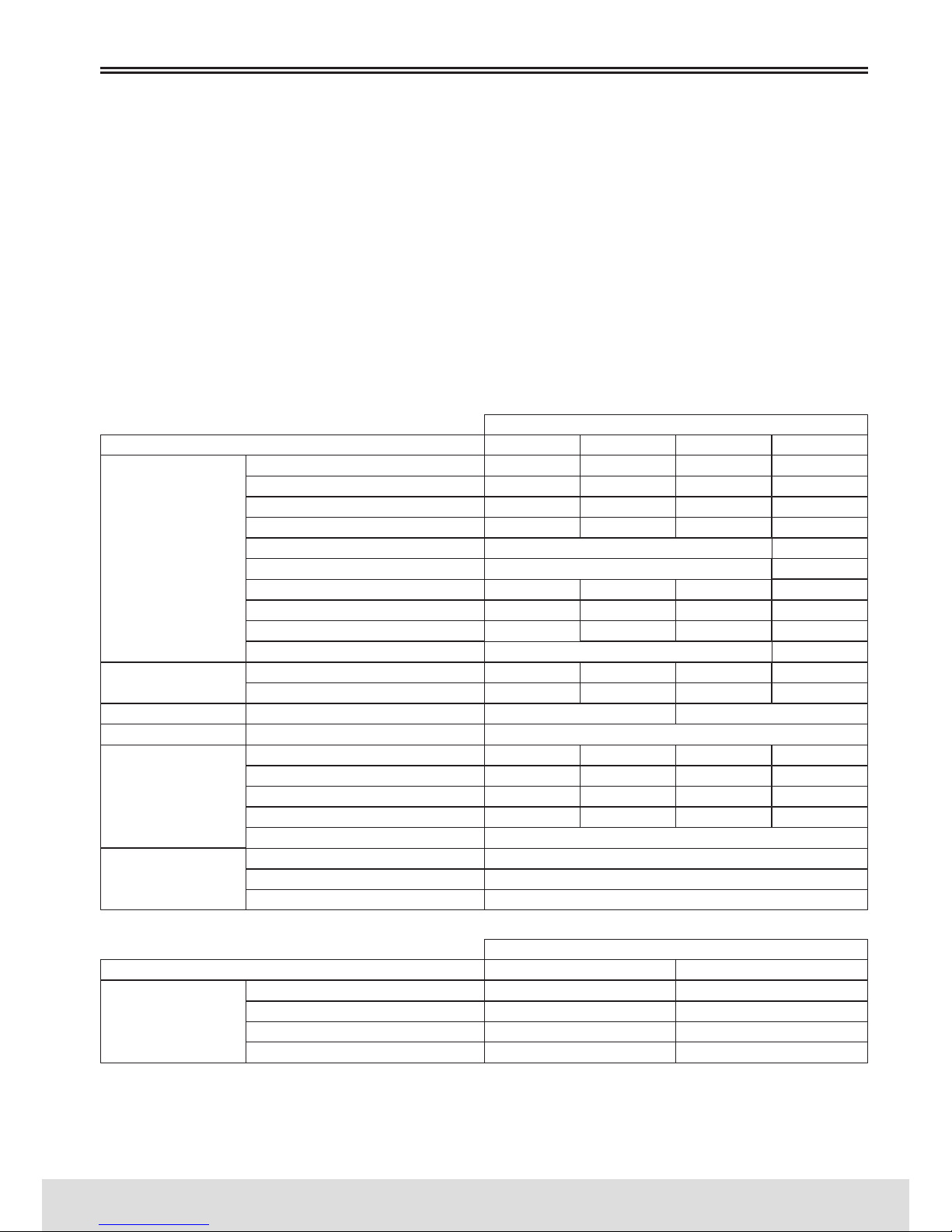
Measurement guide to choose the frame:
USE
USE
<165
From 9 Years
165-175
RIDER HEIGHT (cm)
JUNIOR RIDER (Years)
175-185
From 7 Years
185-195
WARRANTY REGISTRATION
S (14”-15,5”)
M (18”) L (20”)
ONE SIZE
ONE SIZE
ONE SIZE
ONE SIZE
ONE SIZE
Page 10
10
// USER’S MANUAL
ENGLISH
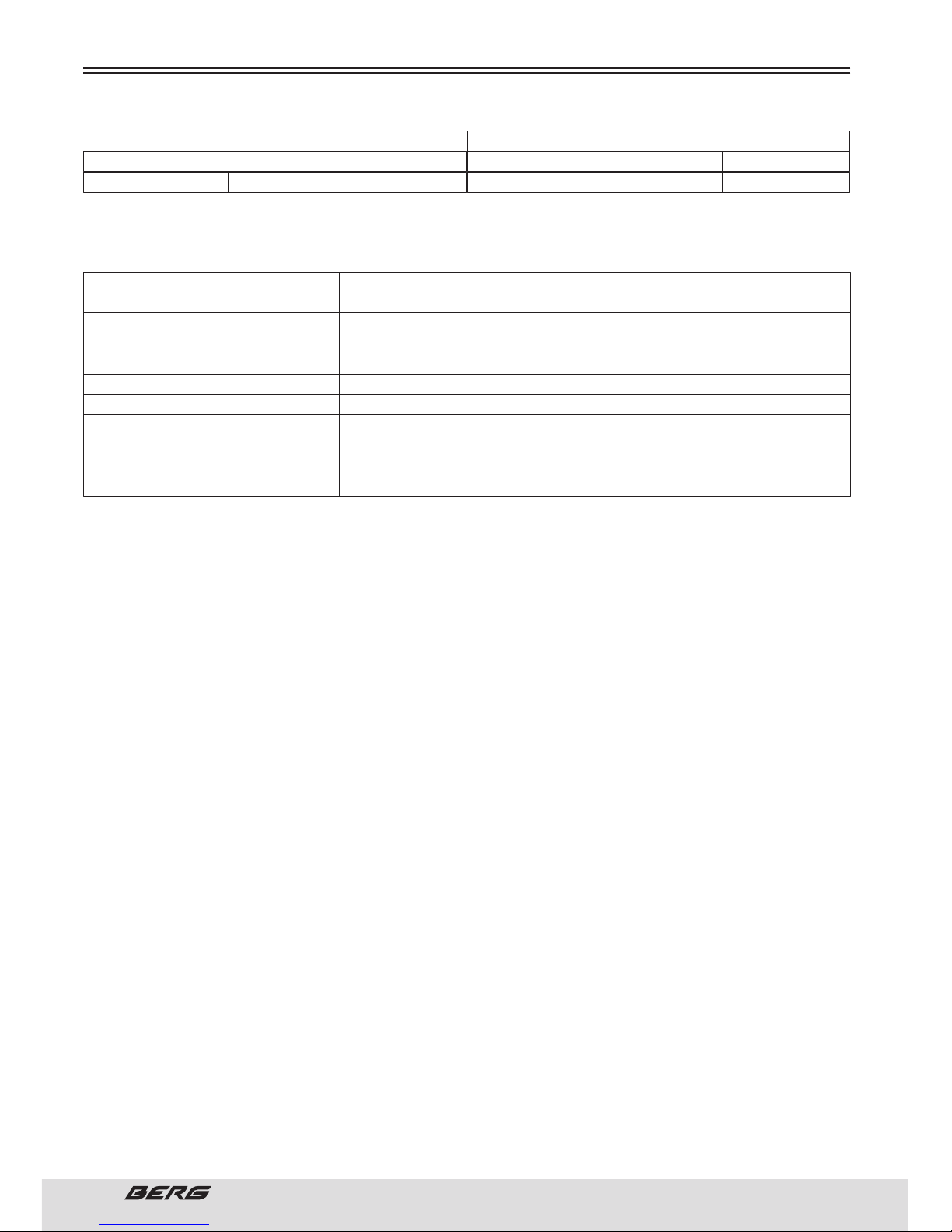
Authorized and recommended maximum weight (Cyclists, bicycles and accessories):
WARRANTY REGISTRATION
12” wheel (One Size)
VERTEX/TRAILROCK/STUKA/TRAIL
SPORTCROSS/VOSTOK/SIERRA/ COUNTRY
FUEGO/FUEGO CX
E-BIKE
EASY
TREKKING/CLASSIC/PARK/URBAN/FITNESS
TRIBE
BLAST/CHARM (WHEEL 20” AND 24”)
BLAST/CHARM (WHEEL 12”, 14” AND 16”)
MOUNTAIN BICYCLES
ROAD BICYCLES
ELECTRIC BICYCLES
FOLDABLE BICYCLES
LEISURE/TREKKING BICYCLES
BMX BICYCLES
JUNIOR BICYCLES
KID BICYCLES
128 kg
120 kg
135 kg
110 kg
135 kg
100 kg
85 kg
55 kg
14” wheel (One Size) 16” wheel (One Size)
BLAST/CHARM SERIESKIDS
USE
TYPE OF BICYCLE SERIES MAXIMUM WEIGHT
(BICYCLE+CYCLIST+ACCESSORIES)
3-5 Years 4-6 Years 5-7 Years
KID RIDER (Years)
Page 11
11
ENGLISH
www.bergcycles.com
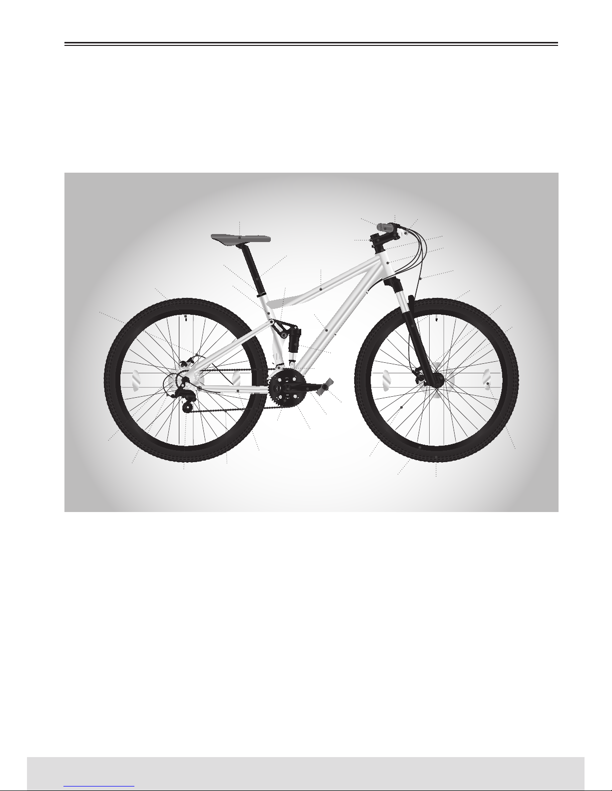
MOUNTAIN BICYCLES
Mountain bikes are designed to provide maximum comfort over a wide variety of surfaces paths. Wider
handlebars and a well positioned shift lever make them very easy to control. e wider rims and tires
give you a smoother ride and better traction on rough surfaces. e frame and fork on mountain bikes
are generally more robust than the ones on race bicycles.
PARTS IDENTIFICATION
GRIP
HANDLEBAR
BRAKE LEAVERS
HEADSET
HEAD TUBE
BRAKE CABLE
FORK
STEM
TOP TUBE
LINK
DOWN TUBE
REAR
SHOCK
FRONT
DERAILLEUR
SADDLE
SEATPOST
SEATPOST CLAMP
SEAT TUBEVALVE
WHEEL
REFLECTOR
TIRERIM
SPOKE
REAR
BRAKE
FRONT
BRAKE
FRONT
HUB
GEAR CONTROL
CABLE
BRAKE
CABLE
REAR
DERAILLEUR
CHAIN
CHAINSTAY
CHAINRING
CRANKSET
CRANK
PEDAL
Page 12
12
// USER’S MANUAL
ENGLISH
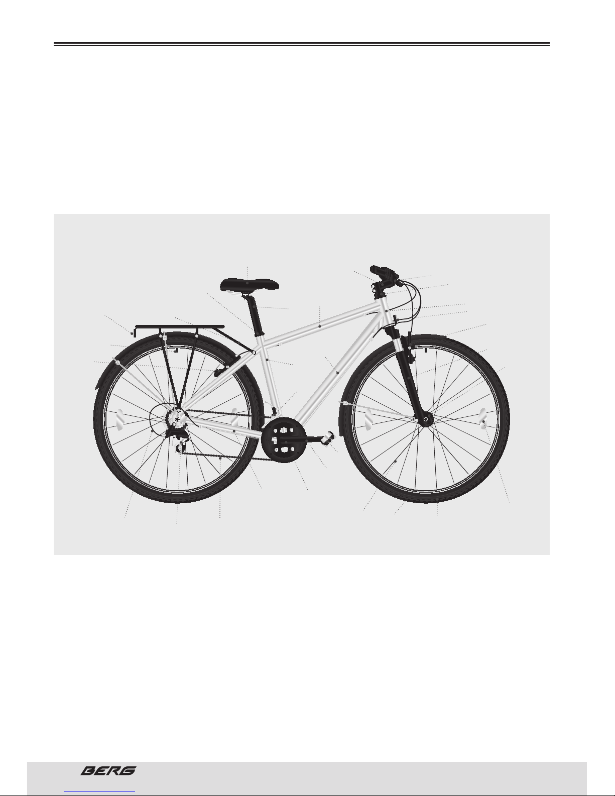
LEISURE / TREKKING BICYCLES
In general, these bikes must have 28/700C sized wheels, although some have narrower tires (26’’ models), and have 21-27 speed. ey combine a road/mountain with comfort saddle and handlebar position
with wider tires and wheel diameters of road bikes. ey are excellent for use on muddy trails or smooth
pavements, but it is not intended to be great road bikes or great mountain bikes. By having the seat
cushions and generally more comfortable handles they provide a more comfortable drive. ese bikes
are preferred by professional riders and amateurs who ride more often on the road, but want a greater
agility and speed than the wide tires on the 26’’ offer.
PARTS IDENTIFICATION
STEM
HANDLEBAR
HEADSET
HEAD TUBE
FRONT REFLECTOR
FORK
TOP TUBE
DOWN TUBE
FRONT
DERAILLEUR
SADDLE
SEATPOST
SEATPOST CLAMP
REAR REFLECTOR
SEAT TUBE
VALVE
WHEEL
REFLECTOR
TIRE
RIM
SPOKE
REAR
BRAKE
FRONT
BRAKE
FRONT
HUB
GEAR CONTROL
CABLE
BRAKE
CABLE
REAR
DERAILLEUR
CHAIN
CHAINSTAY
CRANKSET
CRANK
PEDAL
Page 13
13
ENGLISH
www.bergcycles.com
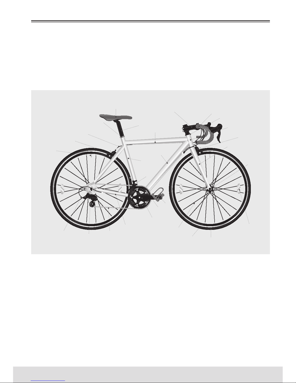
ROAD BICYCLES
In general, these bikes must have 28/700C sized wheels and 16-30 speeds. ey are designed for road
surfaces, increased aerodynamics and speed. ey have softer and narrow tires and “face down” handlebar extenders, and often have fine saddles. ese bikes are for riders who want more speed, go longer
distances, or a more intense aerobic performance, road models are usually lighter and have a slightly
shorter wheel base for a more agile and faster response.
PARTS IDENTIFICATION
STEM HANDLEBAR
HEADSET
HEAD TUBE
FORK
TOP TUBE
DOWN TUBE
FRONT
DERAILLEUR
SADDLE
SEATPOST
SEATPOST CLAMP
SEAT TUBE
VALVE
WHEEL
REFLECTOR
TIRERIM
SPOKE
REAR
BRAKE
FRONT
BRAKE
FRONT
HUB
GEAR CONTROL
CABLE
BRAKE
CABLE
REAR
DERAILLEUR
CHAIN
CHAINSTAY
CRANKSET
CRANK
PEDAL
Page 14
14
// USER’S MANUAL
ENGLISH
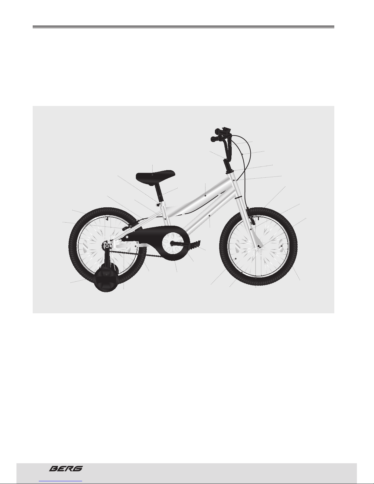
BMX/JUNIOR/KID BICYCLES
ese bikes are very popular for general use, and they fit perfectly the young. ey are highly valued for
their simple but solid construction, and because of their lower need for maintenance.
PARTS IDENTIFICATION
STEM
HANDLEBAR
BRAKE CABLES
HEADSET
HEAD TUBE
FORK
TOP TUBE
DOWN TUBE
SADDLE
SEATPOST
SEATPOST CLAMP
SEAT TUBE
VALVE
WHEEL
REFLECTOR
TIRE
RIM
SPOKE
REAR
BRAKE
FRONT
BRAKE
FRONT
HUB
BRAKE
CABLE
TRAINING
WHEELS
CHAIN
CHAINSTAY
CRANKSET
CRANK
PEDAL
Page 15
15
ENGLISH
www.bergcycles.com
NECESSARY TOOLS
Your new bike was assembled and tuned at the factory and then partially disassembled for shipping. It’s
probable that you’ve bought the bike completely assembled and ready to use or in a box and partially
disassembled. e following instructions allow you to assemble the bike in order to enjoy it for years.
For more details of the inspection, lubrication, maintenance and adjustments in any area, please consult
the respective sections of this manual. If you have any uncertainty regarding your ability to properly
assemble this unit, please consult a qualified expert before using it. If you need any replacement parts
or if you have any questions concerning the assembly of your bicycle please contact us.
To prevent injury, this product should be mounted properly before being used.
If you bought the bike pre-assembled, we recommend that you review all the assembly instructions and
perform the checks specified in this manual before using.
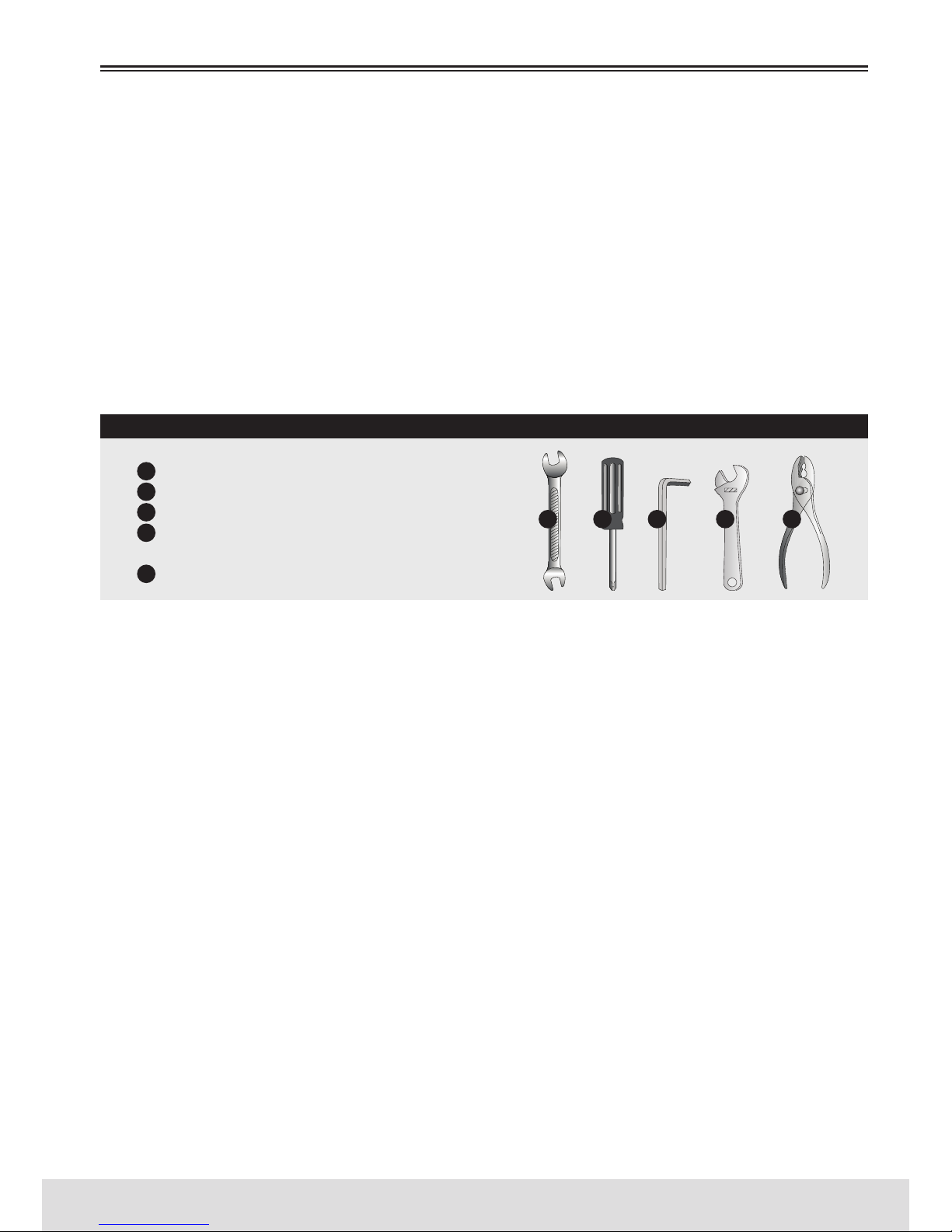
NECESSARY TOOLS
Mouth Wrench
Philips Screwdriver
Allen Wrench 4mm, 5mm, 6mm and 8mm
Adjustable wrench or combination
wrench, 9mm, 10mm, 14mm and 15mm
Pliers to cut wires
ABOUT THIS
It is important for you to understand your new bicycle. By reading this manual before you go out on your
first ride, you’ll know how to get better performance, comfort, and enjoyment from your new bicycle.
It is also important that your first ride on your new bicycle is taken in a controlled environment, away
from cars, obstacles, and other cyclists.
GENERAL WARNING
Bicycling can be a hazardous activity even under the best of circumstances. Proper maintenance of your
bicycle is your responsibility as it helps reduce the risk of injury. is manual contains many “Warnings”
and “Cautions” concerning the consequences of failure to maintain or inspect your bicycle. Many of the
warnings and cautions say “you may lose control and fall.” Because any fall can result in serious injury
or even death, we do not repeat the warning of possible injury or death whenever the risk of falling is
mentioned.
SPECIAL NOTE FOR PARENTS
It is a tragic fact that most bicycle accidents involve children. As a parent or guardian, you bear the responsibility for the activities and safety of your minor child. Among these responsibilities are to make
sure that the bicycle which your child is riding is properly fitted to the child; that it is in good repair
and safe operating condition; that you and your child have learned, understand and obey not only the
applicable local motor vehicle, bicycle, and traffic laws, but also the common sense rules of safe and
responsible bicycling. As a parent, you should read this manual before letting your child ride the bicycle.
Please make sure that your child always wears an approved bicycle helmet when riding.
PARTS IDENTIFICATION
1
2
3
4
5
1 2 3 4 5
Page 16
16
// USER’S MANUAL
ENGLISH
When choosing a new bicycle, the selection of the frame size is an important security aspect to be taken
into account. Most bike sizes are in a range of frame sizes.
ese sizes usually refer to the distance between the centre of the bracket and the top of the saddle
tube.
For a safe and comfortable cycling, there must be a clearance of at least 1 to 2 inches between the area
between the rider’s legs and the top tube of the bicycle frame, and the rider must place his feet on the
floor while holding the bike with one leg on each side.
e ideal distance varies between types of bicycles and cyclists ‘preferences. is will make it easier and
safer to stay on the bike frame when you must get off the saddle in certain situations, such as when
traffic suddenly stops. Women can use men bicycles.
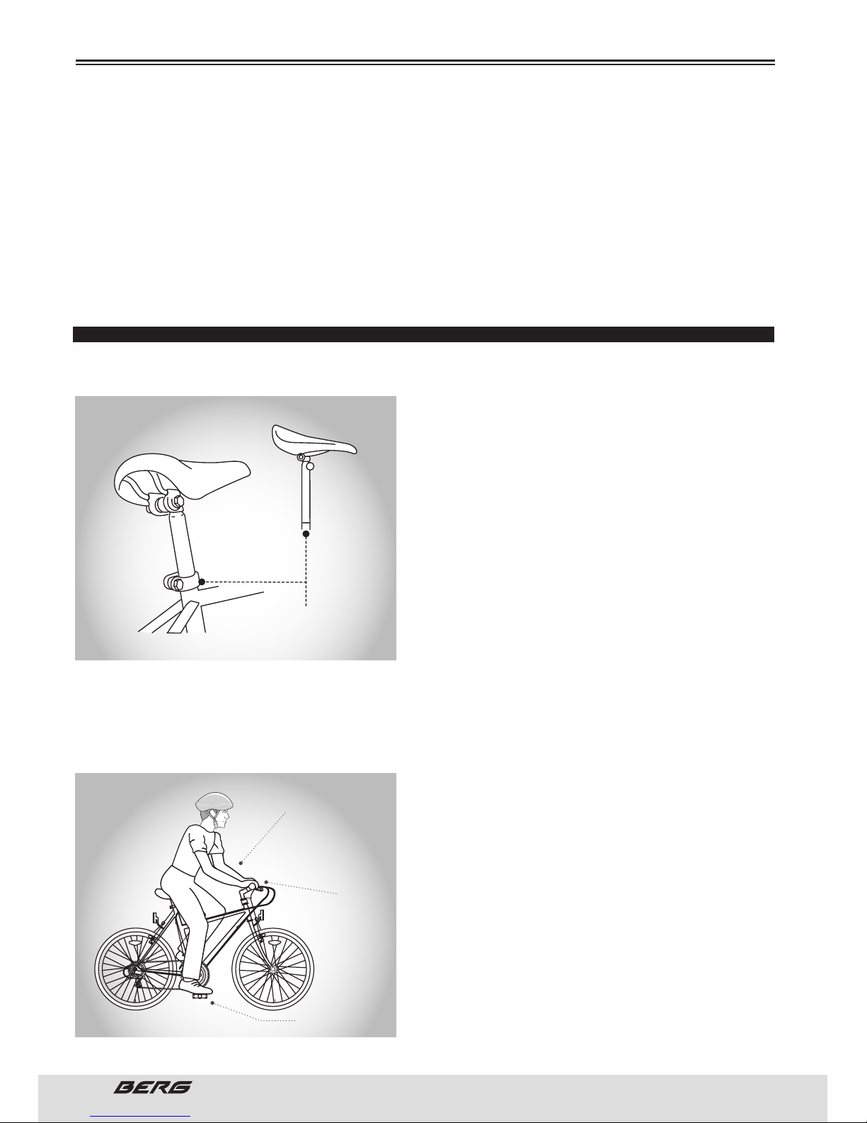
BICYCLE ADJUSTMENTS
SADDLE HEIGHT
In order to obtain the most comfortable riding position
and offer the best possible pedalling efficiency, the seat
height should be set correctly in relation to the rider’s
leg length. e correct saddle height should not cause
leg strain from over-extension, and the hips should not
rock from side to side when pedalling.
While sitting on the bicycle with one pedal at its lowest point, place the ball of your foot on that pedal. e
correct saddle height will allow the knee to be slightly
bent in this position. If the rider then places the heel of
that foot on the pedal, the leg should be almost straight.
Under no circumstances should the seat post extend
from the frame beyond its “Minimum Insertion” or
“Maximum Extension” mark. If your seat post extends
from the frame beyond these markings, the seat post or frame may break, which could cause you to lose
control and fall. Prior to your first ride, be sure to tighten the saddle adjusting mechanism properly.
A loose saddle clamp or seat post binder can cause damage to the bicycle or can cause you to lose control and fall. Periodically check to make sure that the saddle adjusting mechanism is properly tightened.
For more information see page 43.
REACH
To obtain maximum comfort, the rider should not overextend his or her reach when riding. To adjust this distance, the position of the seat can be altered in relation
to the seat post.
(See page 43 how to adjust the saddle clamp).
BEFORE USING THE BICYCLE
HANDLEBAR HEIGHT
MORE OR LESS AS THE
SEAT HEIGHT
PEDAL IN
LOWEST POSITION
ARMS NOT TOO MUCH
EXTENDED
MAXIMUM HEIGHT
MINIMUM INSERTION MARK
(SHOULD NOT BE VISIBLE)
Page 17
17
ENGLISH
www.bergcycles.com
Make sure the front and rear brake function
perfectly. Make sure that the brake control
cables are lubricated and have no obvious
wear.
Make sure your tires are inflated to
recommended pressure as indicated at the
side of the tire and do not shows excessive
wear.
Make sure that the rims of the wheel
running normally and that pose no obvious
twist. Make sure they have the correct
tension and in the closed position.
Make sure you are properly fitted and
adjusted.
Make sure the pedals are securelly at-
tached to the brackets. Make sure that the
cranksets are tight to the bracket motion.
Verify that the front and rear gears work
properly.
Verify that the frame and fork are not bent
or broken.
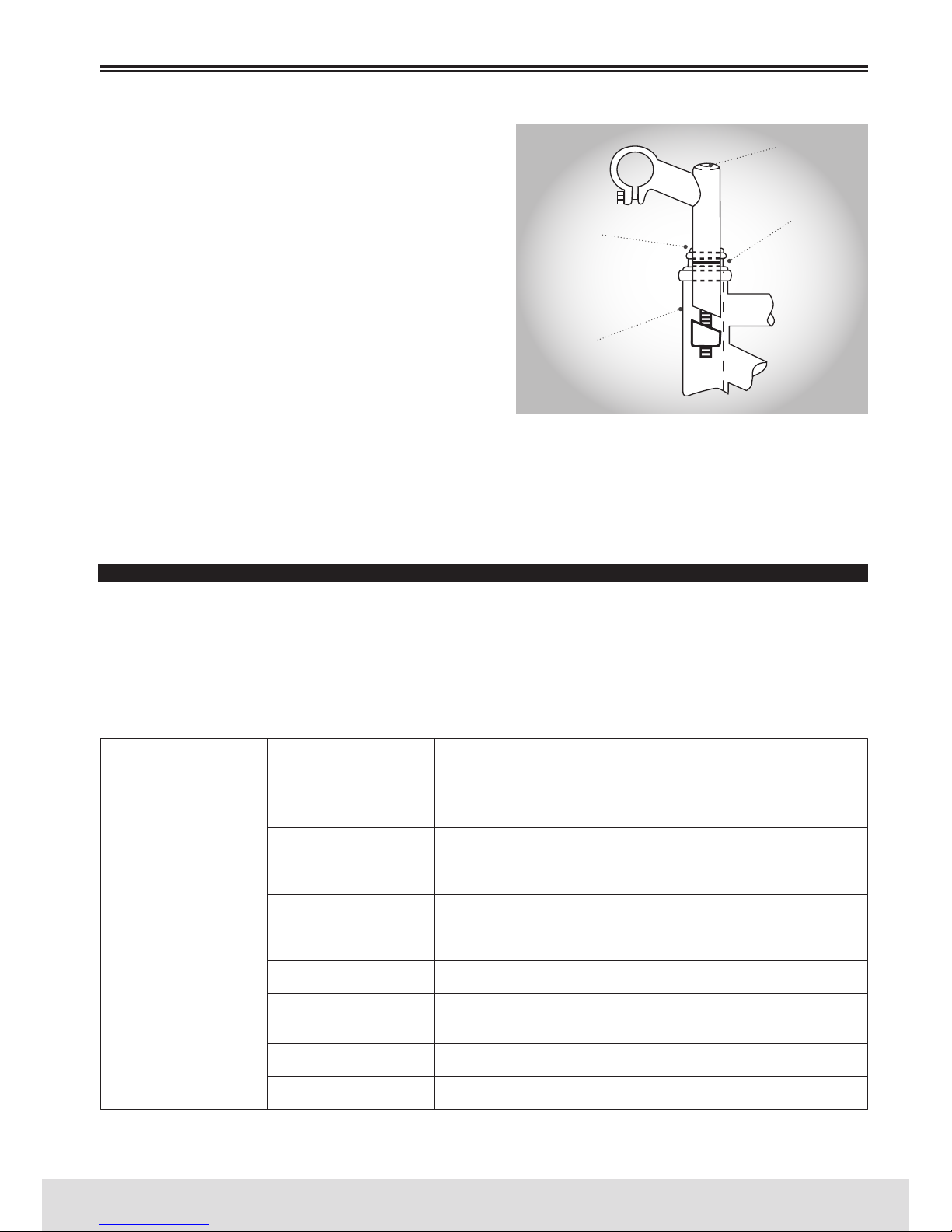
HANDLEBAR HEIGHT
Maximum comfort is normally achieved when the handlebar height is levelled with the saddle height. You can
experiment different heights until you find the most
comfortable position.
NOTE: e Aheadset steering does not let you to adjust
the height in the stem.
e stem’s “Minimum Insertion” mark must not be visible above the top of the headset. If the stem is extended beyond this mark, the stem may break or damage
the fork’s steer tube, which could cause you to lose
control and fall.
Failure to properly tighten the stem binder bolt, the
handlebar binder bolt, or the bar end extension clamping bolts may compromise steering action, which could cause you to lose control and fall. Place the
front wheel of the bicycle between your legs and attempt to twist the handlebar/stem assembly using a
reasonable amount of force. If you can twist the stem in relation to the front wheel, turn the handlebars
in relation to the stem, or turn the bar end extensions in relation to the handlebar, you must tighten the
appropriate bolts accordingly.
For more information see page 41.
MAINTENANCE AND SAFETY CHECKS PLAN
Local distributor offers the first full revision to the bike. is review should be done after the first five hours
of use and up to a limit of two months after the date of purchase. e review may not be done on time.
e maintenance and safety checks plan should be carried out according to the following schedule:
SCHEDULE 1:
BEFORE USING THE BICYCLE
FREQUENCY COMPONENT VERIFICATION PROCEDURE
Before
using the
bicycle
Brake
Tires/ Inner tubes
Wheels
Steering
Brackets and pedals
Gears
Frame and Fork
Braking and broken
Cables
Pressure
Rim and spokes
Wheel clamping
Handlebar and stem
Pedals and brackets
Gears and broken wires
Cracks or creases
STEM TIGHTENING SCREW
MAXIMUM HEIGHT
MINIMUM INSERTION MARK
HANDLEBAR FIXING BOLT
2 ½ (64mm)
SURPLUS
Page 18
18
// USER’S MANUAL
ENGLISH
SCHEDULE 2:
SCHEDULE 3:
NOTICE:
Whenever anything unusual should happen proceed with the repairs.
All bikes must be subject to periodic revisions.
A good bicycle maintenance can preserve their unique qualities of safety and usage.
Do not forget to store your bike in a dry sheltered place and away from saline environments.
Do not forget to regularly clean the heads of all bolts and spokes of your bicycle. Manufacturers usually
use steel that ensures the adequate strength of the components.
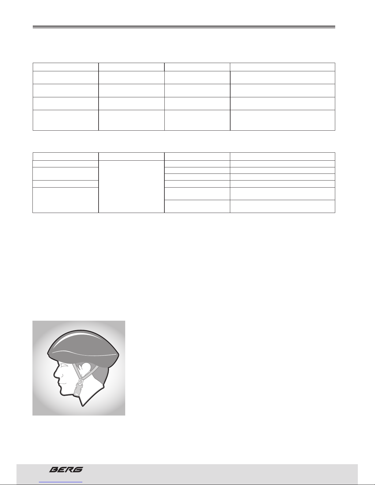
HELMETS
It is strongly advised that a properly fitting, ASTM or SNELL approved, bicycle safety helmet be worn at
all times when riding your bicycle. In addition, if you are carrying a passenger in a child safety seat, they
must also be wearing a helmet.
e correct helmet should: be comfortable - have good ventilation - fit
correctly - cover forehead
Always wear a properly fitted helmet which covers the forehead when
riding a bicycle. Many countries require specific safety devices. It is
your responsibility to familiarize yourself with the laws of the state
where you ride and to comply with all applicable laws, including properly equipping yourself and your bike as the law requires. Reflectors are
important safety devices which are designed as an integral part of your
bicycle. ese reflectors are designed to pick up and reflect street lights
and car lights in a way that helps you to be seen and recognized as a
moving bicyclist. Check reflectors and their mounting brackets regularly to make sure they are clean, straight, unbroken and securely mount-
ed. Ask your dealer to replace damaged reflectors and straighten or tighten those who are bent or loose.
BEFORE USING THE BICYCLE
Clean and then brush or sprinkle
3 drops of oil
Disassemble and Lubricate
Lubricate
Disassemble and Lubricate
Clean/lubricate
Tighten
Lubricate with Teflon oil
Cleaning and lubrication at general supplier
Oil Change and lubrication with Teflon oil
at supplier
Full inspection and replacement
(seals / oil) at supplier
FREQUENCY
FREQUENCY
COMPONENT
COMPONENT
LUBRICANT
AREA
PROCEDURE
PROCEDURE
Weekly
Montly
Every 6 months
Annually
After any use
After 25 hours
After 50 hours
After 100 hours
Chain/Derraileur
Brake levers
Gears levers
Brake and gears cables
Hubs and sprockets
Brackets/Pedals
Wheel bearings
Headset
Saddle seatpost
Suspension
Shock
Lubricant or light oil for
chains
Lithium based grease
Lubricant or light oil for
chains
Lithium based grease
Legs and sealing zone
Screws tightening
Sealing zone
Suspension functioning
Blocking or travel adjust
below the cover
Suspension functioning
Page 19
19
ENGLISH
www.bergcycles.com
RIDING SAFETY
GENERAL RULES
When riding obey the same road laws as all other road vehicles, including giving way to pedestrians,
and stopping at red lights and stop signs. For further information, contact the Road Traffic Authority in
your State.
Ride predictably and in a straight line. Never ride against traffic.
Use correct hand signals to indicate turning or stopping.
Ride defensively. To other road users, you may be hard to see.
Concentrate on the path ahead. Avoid pot holes, gravel, wet road markings, oil, curbs, speed bumps,
drain grates and other obstacles.
Cross train tracks at a 90 degree angle or walk your bicycle across.
Expect the unexpected such as opening car doors or cars backing out of concealed driveways.
Be extra careful at intersections and when preparing to pass other vehicles.
Familiarize yourself with all the bicycle’s features. Practice gear shifts, braking, and the use of toe clips
and straps, if installed.
If you are wearing loose pants, use leg clips or elastic bands to prevent them from being caught in the
chain.
Wear proper riding attire and avoid open toe shoes.
Don’t carry packages or passengers that will interfere with your visibility or control of the bicycle.
Don’t use items that may restrict your hearing.
Do not lock up the brakes. When braking, always apply the rear brake first, then the front.
e front brake is more powerful and if it is not correctly applied, you may lose control and fall.
Maintain a comfortable stopping distance from all other riders, vehicles and objects.
Safe braking distances and forces are subject to the prevailing weather conditions.
WET WEATHER
WE DO NOT RECOMMEND RIDING IN THE RAIN
In wet weather you need to take extra care.
Brake earlier, you will take a longer distance to stop.
Decrease your riding speed, avoid sudden braking and take corners with additional caution.
Be more visible on the road.
Wear reflective clothing and use safety lights.
Pot holes and slippery surfaces such as line markings and train tracks all become more hazardous when
wet.
NIGHT RIDING
WE DO NOT RECOMMEND RIDING AT NIGHT
Ensure bicycle is equipped with a full set of correctly positioned and clean reflectors.
Refer to page 39 of this manual.
Use a properly functioning lighting set comprising of a white front lamp and a red rear lamp.
If using battery powered lights, make sure batteries are well charged.
Some rear lights available have a flashing mechanism which enhances visibility.
Wear reflective and light coloured clothing.
Ride at night only if necessary. Slow down and use familiar roads with street lighting, if possible.
BEFORE USING THE BICYCLE
Page 20
20
// USER’S MANUAL
ENGLISH
PEDALLING TECHNIQUE
Place the front of the foot in the pedal centre.
When riding, make sure that your knees are parallel with the bicycle frame.
To reduce the impact, keep your elbows slightly bent.
Learn how to use the gears appropriately.
For more information see page 21 to 23.
MOUNTAIN TECHNIQUE
Place a lower gear before going up and continue to reduce the gears as necessary to maintain the pedalling speed.
If you are in the lowest gear and you are struggling, put your feet on the pedals. is will give you more
power each time you pedal.
In downhill, use the higher gears to avoid pedalling fast.
Do not exceed a comfortable speed, maintain control and be particularly careful.
CURVING TECHNIQUE
Slightly brake before making the curves and get ready to lean forward on the curve.
Keep the pedal on the inside of the curve in a 12 hours position, and place the knee of this leg slightly
turned in the direction you’re turning.
Keep the other leg right, not pedal fast or tight curves.
RULES FOR CHILDREN
To avoid accidents, teach children good riding skills with an emphasis on safety from an early age.
Children should be supervised by an adult.
1. Many states require that children wear a helmet while cycling. Always wear a properly fitted helmet.
2. Do not play in driveways or the road.
3. Do not ride on busy streets.
4. Do not ride at night.
5. Obey all the traffic laws, especially stop signs and red lights.
6. Be aware of other road vehicles behind and nearby.
7. Before entering a street: Stop, look left, right, and left again for traffic. If there’s no traffic, proceed
into the roadway.
8. If riding downhill, be extra careful. Slow down using the brakes and maintain control of the steering.
9. Never take your hands off the handlebars, or your feet off the pedals when riding downhill.
e Consumer Protection Safety Commission advises that the riding of small wheel diameter bicycles at
excessive speeds can lead to instability and is not recommended.
Children should be made aware of all possible riding hazards and correct riding behaviour before they
take to the streets.
Do not leave it up to trial and error.
GEAR OPERATION
e majority of existing multispeed bikes are equipped with what is known as gears or derailleur. Operate using a system of levers and mechanisms to divert the drive chain and sprockets between gears
of different sizes. e purpose of speed gears is to allow you to maintain a regular and steady ride in
various conditions. is means that you will be less tired during cycling, without exerting undue pressure or pedalling to quickly when descending a slope. Bikes have a wide variety of settings, speed gears
from 3 to 30 speeds. A bike with 5 or 6 speeds has only one front crankset (plate), a rear derailleur and
sprockets 5 or 6 in the rear hub.
BEFORE USING THE BICYCLE
Page 21
21
ENGLISH
www.bergcycles.com
e bikes with more gears also have a front derailleur, a front plate with 2 or 3 sprockets and up to 10
sprockets on the rear hub.
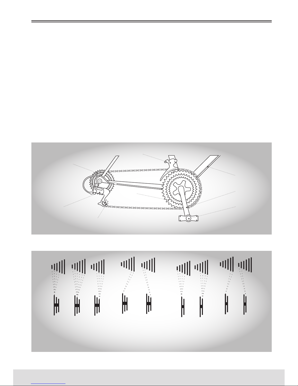
OPERATING PRINCIPLES OF DERAILLEURS
e operating principles are the same regardless of the number of speeds.
e front derailleur works through the left shifter and the rear derailleur through the right shifter. You
must ride forward for the gears to work. You cannot shift gears with the derailleurs if you are stopped
or pedalling backward. Before switching speed, reduce the pressure while pedalling. To achieve a smooth
gear of speed when approaching a mountain change to a lower gear change before the pedalling speed
decreases too much. When coming to a stop, go to a lower gear so that it will be easier to start pedalling again. If, after selecting a new position, you hear a slight sound of friction gears on the front or
rear, gently adjust the appropriate change using the turnbuckles until the noise disappears. To achieve
optimum performance and greater life of the chain, it is recommended to avoid using extreme positions
gears combinations for long periods.
RECOMMENDED COMBINATIONS OF GEARS
BEFORE USING THE BICYCLE
CONTROL CABLE
DERAILLEUR
FRONT DERAILLEUR
REAR DERAILLEUR
FREEWHEEL
SPROCKETS
TRANSMISSION
DERAILLEUR PULLEY
FRONT CRANKSET
CRANKSET
PEDAL
HIGH HIGH
3
2
1
2
1
MIDDLE LOW LOWTHESE COMBINATIONS ARE NOT
RECOMMENDED TO ACHIEVE
OPTIMUM PERFORMANCE
THESE COMBINATIONS ARE NOT
RECOMMENDED TO ACHIEVE
OPTIMUM PERFORMANCE
Page 22
22
// USER’S MANUAL
ENGLISH
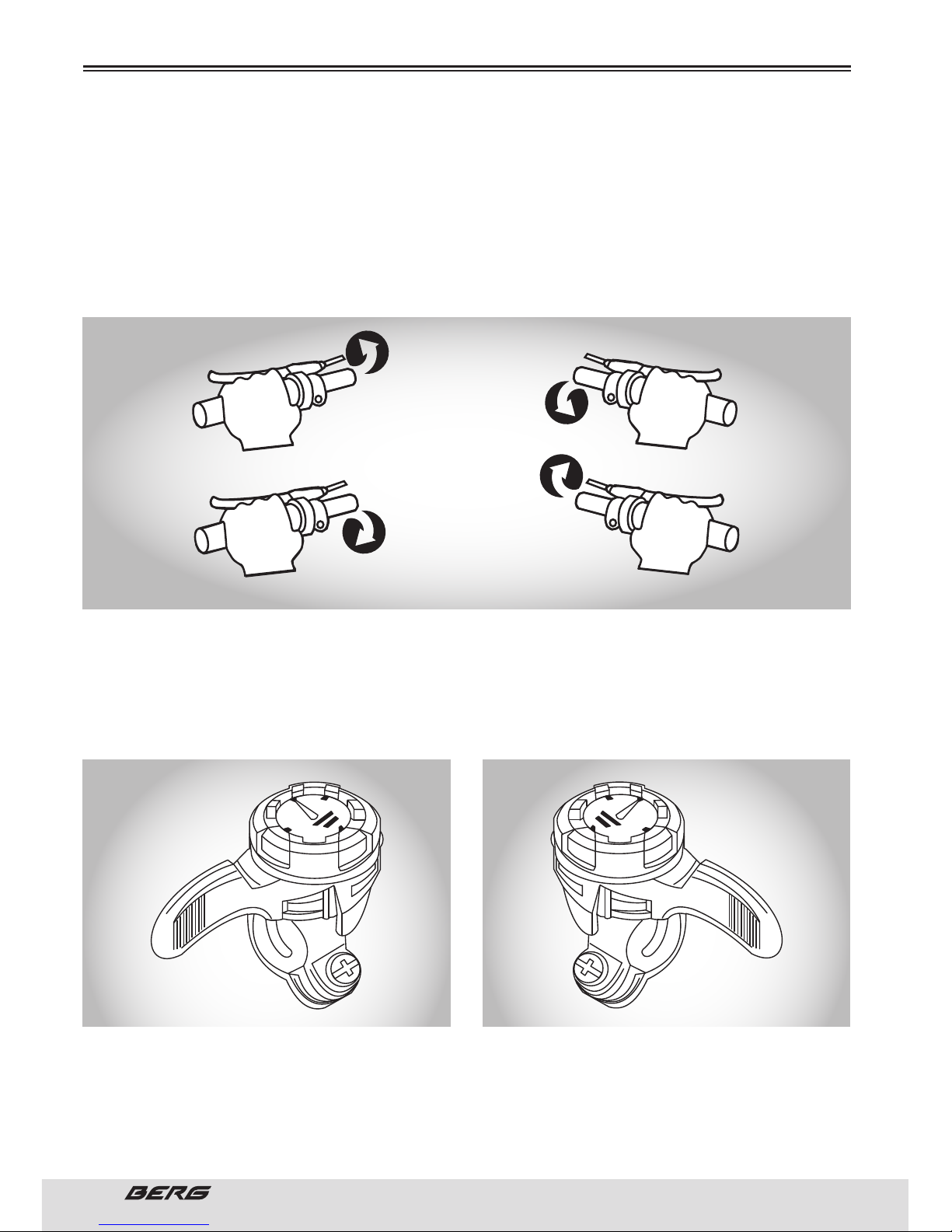
OPERATION OF KNOBS HANDLE
Some bikes now come with a gear mechanism called Grip Shift. built into the handles and knobs that
do not use separate handles. e mechanism is built inside the handle, placed between the thumb and
forefinger. To select a lower gear, turn right fist toward you to engage a larger rear sprocket. You can
make changes one at a time, moving with a click of the Grip Shift. or multiple changes to by moving it
continuously. Turning the left handle forward in the opposite direction to you, you can choose a smaller
plate. To select a higher gear, turn the right fist forward in the opposite direction or the other to engage
a smaller rear sprocket. To engage a larger front plate, turn the left fist toward you. Simple gear changes
can be made by turning one click at a time, and multiple gear changes with a larger rotation.
THUMB SHIFTERS (MOUNTED ON TOP)
Some mountain bikes are equipped with shift lever mounted on top of the handlebar that are operated
with the thumb. To select a lower and lighter gear, switch to a larger rear sprocket and a smaller front
plate. Pull back the left shifter to move the front derailleur and pull the right shifter forward to move the
rear derailleur. To select a higher and heavier gear, switch to a smaller rear sprocket and a larger dish.
Push the left shifter forward to the front derailleur and pull the right shifter back to the rear derailleur.
HIGHER GEAR (HEAVIER)
SMALLER REAR SPROCKET
LARGE PLATE
LEFT HAND SHIFTER FORWARD
RIGHT HAND SHIFTER BACK
LOWER GEAR(LIGHTER)
LARGER REAR SPROCKET
SMALL PLATE
LEFT HAND SHIFTER BACK
RIGHT HAND SHIFTER FORWARD
BEFORE USING THE BICYCLE
LOW FRONT GEAR LOW BACK GEAR
HIGH FRONT GEAR
LEFT HAND SHIFTER RIGHT HAND SHIFTER
HIGH BACK GEAR
Page 23
23
ENGLISH
www.bergcycles.com
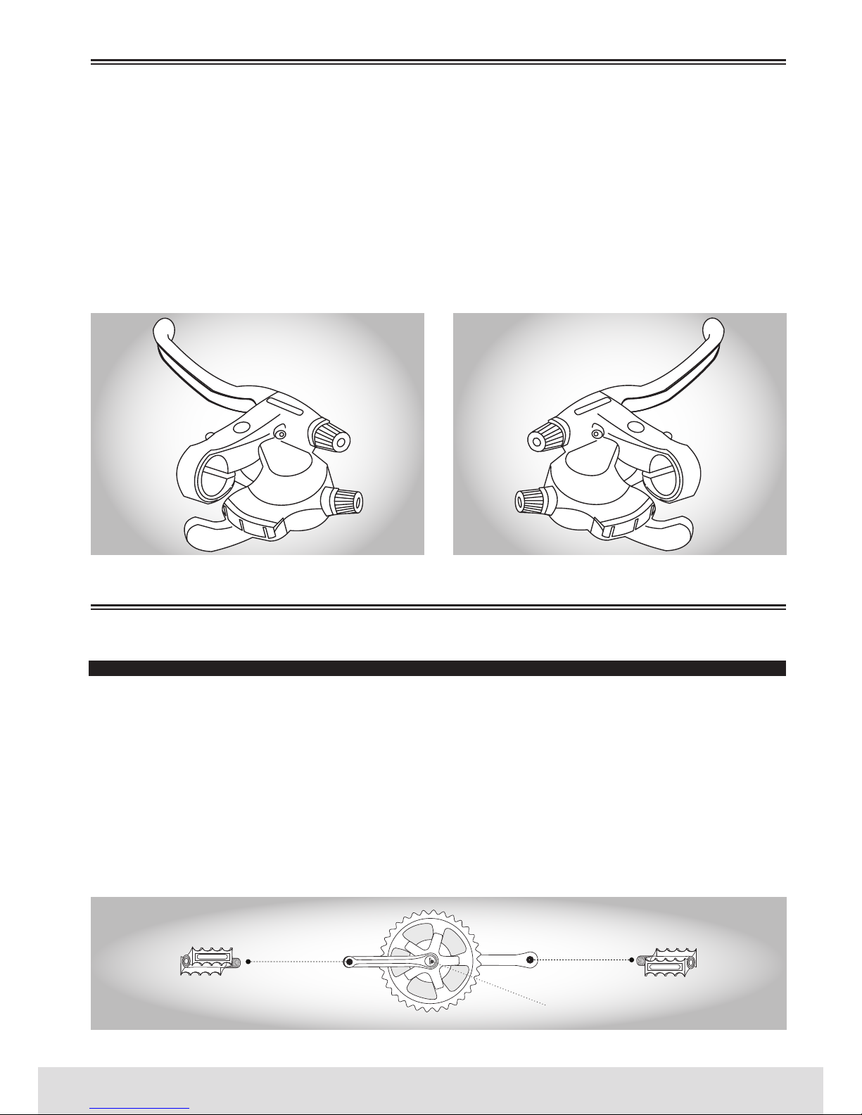
SHIFTERS UNDER THE HANDLEBAR
Currently, most mountain bikes shifters set is mounted at the bottom of the handlebar and is composed
of two levers that operate with the thumb and forefinger. To select a lower gear, push the biger right
shifter (lower) with your thumb to select a larger rear sprocket.
A firm push changes the chain from sprocket, and if you keep pushing, the chain will move through the
various sprockets of the cassette. By pulling the smallest left shifter (top) with the forefinger, the chain
will move from a larger dish to a smaller one.
To select a higher gear, pull the right smaller shifter (top) with the forefinger to engage a smaller rear
sprocket. By pushing the higher left shifter (lower) with the thumb, the chain will move to from a smaller
plate to a larger one. For instructions, see page 21.
PEDALS AND CRANKS
Look for the letters “R” for right, and “L” for left, stamped on each pedal spindle. Start each pedal spindle
by hand to avoid stripping the threads. (Note that the right hand pedal attaches to the chainwheel side
crank arm with a right-hand (clockwise) thread. e left pedal attaches to the other crank arm and
has a left hand (counter-clockwise thread). Tighten with a 15mm narrow open ended wrench. It is very
important that you check the crank set for correct adjustment and tightness before riding your bicycle.
e new brackets can be initially loosened. Once installed the pedals, remove the protective dust covers
from the centre of each bracket. With a 14mm wrench or 8mm Allen wrench tighten the nuts / bolts shaft
firmly (approx. 350 in.lbs / 39,5 N.m) and replace the protective dust covers.
If you have attached the pedal to an incorrect bracket that may cause irreparable damage to the nuts
pedal. Before using the bike for the first time, make sure that the pedals are tighten.
BEFORE USING THE BICYCLE
ASSEMBLY
LEFT HAND SHIFTER RIGHT HAND SHIFTER
ONLY ATTACH THE RIGHT PEDAL ONLY ATTACH THE LEFT PEDAL
PROTECTIVE DUST COVER
IMPORTANT! IMPORTANT!
Page 24
24
// USER’S MANUAL
ENGLISH
ASSEMBLY
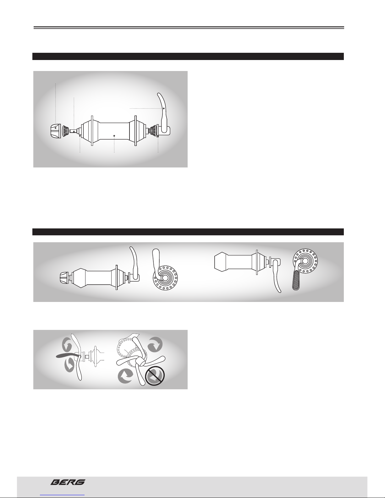
FRONT AND REAR WHEEL
Inspect the wheel hub before adjusting it to the
fork by turning the threaded shaft. You must do it
gently, without lateral movement. Insert the front
wheel between the tips of the fork. Tighten the nuts
using the appropriate 14 or 15mm wrench. Spin the
wheel to make sure it is well placed. Some bikes
have wheel axles that incorporate a mechanism for
quick release (QR). is allows you to take out the
wheel easily, without tools. e mechanism uses a
wide hollow bolt with an adjustment nut on one end
and a lever that operates a turnbuckle at the other
end.
If the wheel axle is placed with a quick opening mechanism, turn the adjusting nut so that the locking
lever moves to the closed position with a steady motion. Halfway to the closed position of the quick
release lever, you should begin to feel a certain resistance to this movement. Do not tighten the quick
release lever and using a wing nut. If the quick release lever moves to the closed position without resistance, the clamping force is insufficient. Move the quick release lever to the open position, tighten the nut
of the quick release lever and replace the lever in the closed position.
CORRECT PLACEMENT OF THE QUICK RELEASE LEVER
1. To place it, turn the lever to the open position so that the curved part may be in the opposite direction
to the bike.
2. While holding the lever with one hand, tighten the nut until it stops.
3. Turn the lever to the closed position. When the
lever is halfway to the closed position, you must
feel a certain resistance to move forward from that
point. If the resistance is not great, open the lever
and tighten the nut in a clockwise direction.
4. Keep turning the lever to the closed position, so
that the curved part of the lever is facing the bike.
5. e wheel is secure when the serrated surfaces
of the quick release fixing parts of the lever come to the surfaces of the frame / fork of the bike.
6. Keep in mind that the procedure is the same as used when placing the quick-release mechanism of
the saddle seatpost.
7. Put the bike in an upright position using the support leg to support it.
If you can fully close the lever for quick release without engaging your fingers in the fork blades to rotate
it, and if the lever does not leave a clear imprint in the palm of your hand, tension is not enough. Open
the lever, turn the adjustment and try again.
LOCKOUT
QUICK RELEASE
LEVER AXIS
QUICK RELEASE
LEVER
SPRINGHUBHUB AXIS
CLOSED POSITION OPEN POSITION
Page 25
25
ENGLISH
www.bergcycles.com
ASSEMBLY
Continue until the quick release lever is closed properly. Secondary restraints do not replace proper grip
of quick release lever. If the quick-release mechanism is not properly tightened, the wheel may come
loose, which could lead you to lose control and fall, causing serious injury or even death. For the rear
wheel, the procedure is similar, taking only attention to the place were the chain was when you’ve disassembled the wheel (check the display of the gear selector) See also page 49 to 51.
BRAKES
Check what kind of brakes your bike is equipped with and refer to the appropriate assembly instructions.
For more information on tuning and maintenance of brakes, see pages 25 to 28.
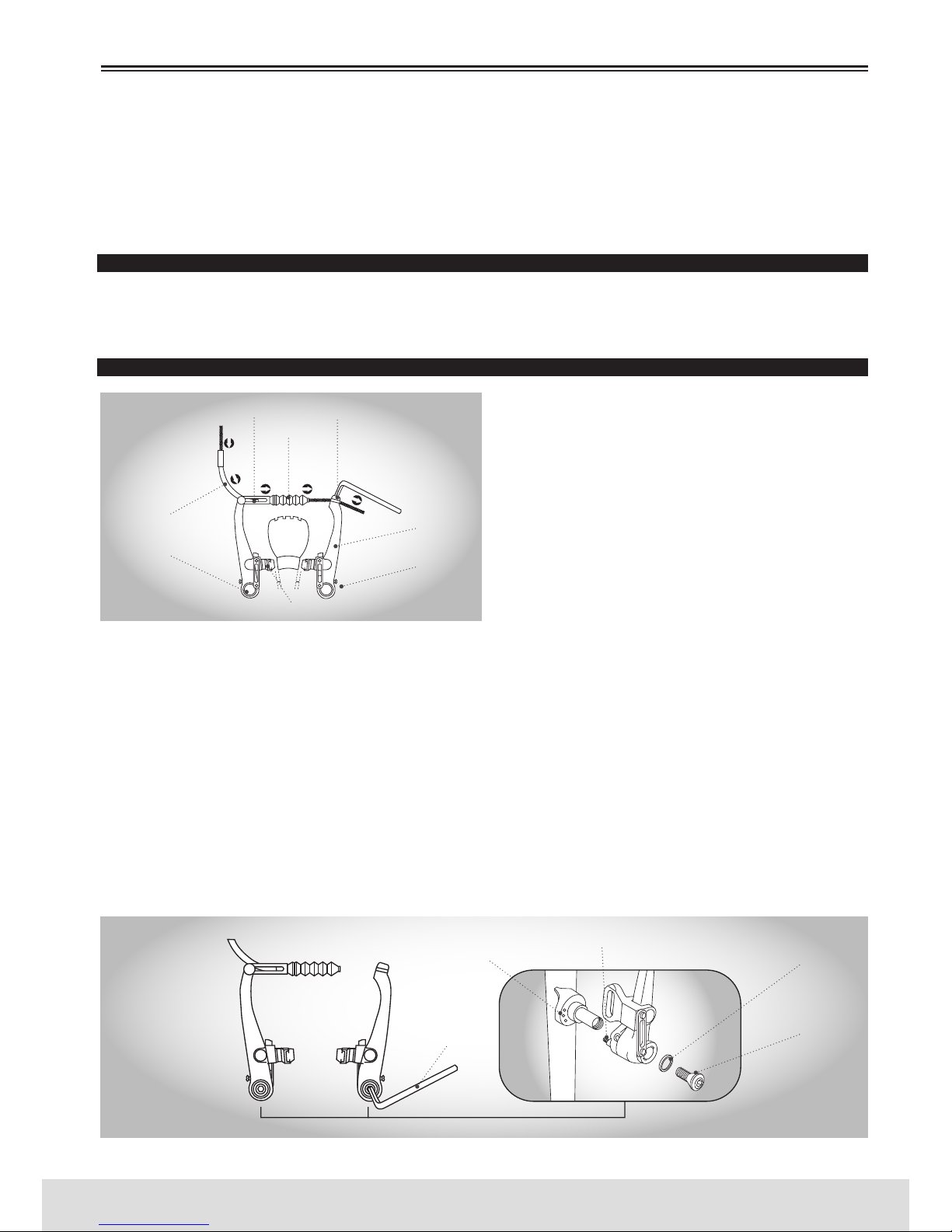
V-BRAKES
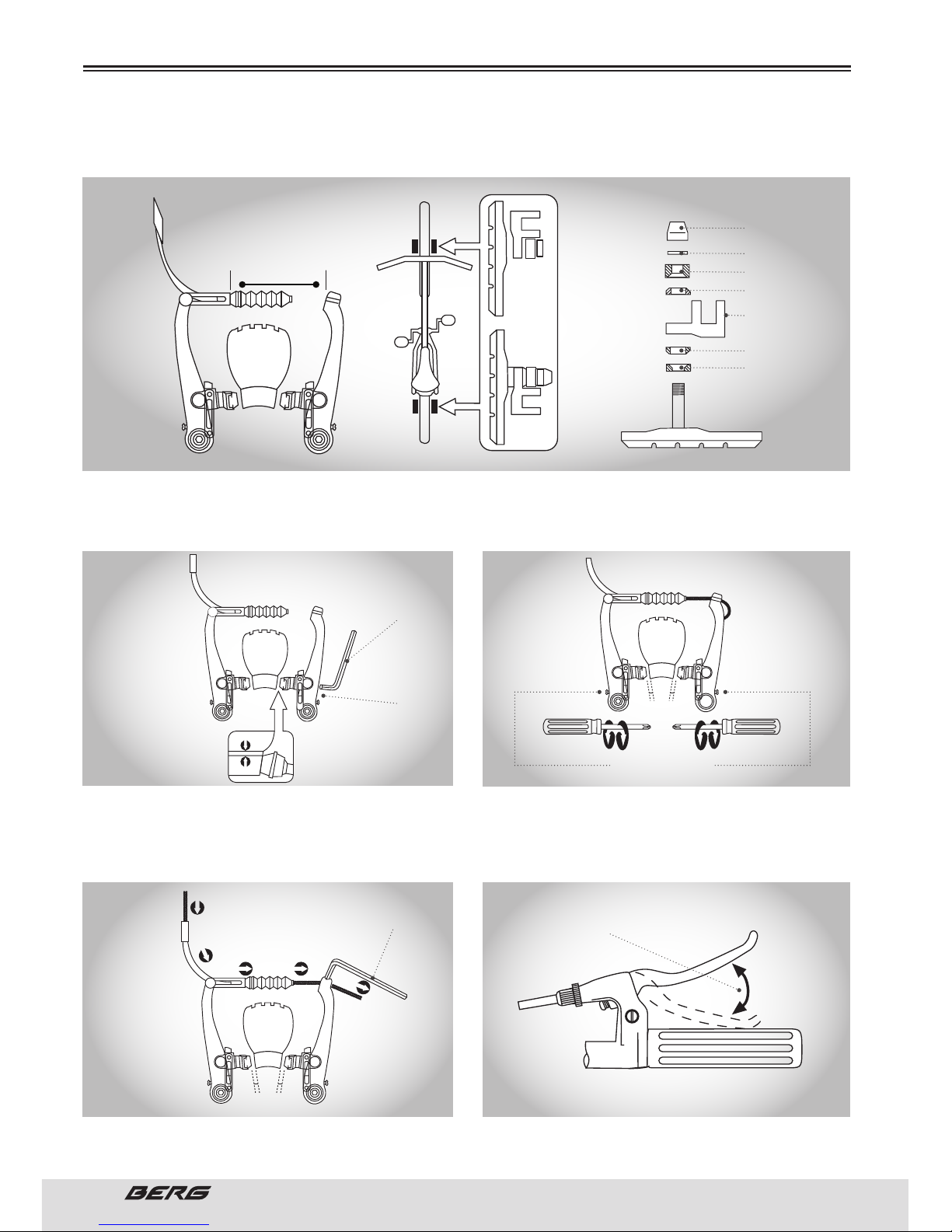
If not already installed, remove the brake cable of box
parts and slide the cable through the larger opening.
e cable spiral sits on the edge of the cable. Slide the
cable through the noodle at the end of brake left arm,
which will make the cable enter the guide. Slide the
brake cable on the cable and position it between the
two brake arms. en loosen the fixation bolt 5mm
at the far right of the brake arm and slide the cable
under the retention ring. Take all the tension of the
cable making sure that there is a distance of 39mm or
more between the end and the beginning of the guide
pin fixation. When the cable is connected to the brake arms, squeeze the brake lever several times, checking
the position of the brake shoes on the rim. e brake shoes should be 1mm away from the rim. If your bicycle
has a V-Brake don’t forget to shake before using. en loosen the 5mm fixation bolt at the far right of the
brake arm and slide the cable under the retention washer. Take all the tension of the cable making sure that
there is a distance of 39mm or more between the end of the guide and the beginning of the fixation pin. When
the cable is connected to the brake arms, squeeze the brake lever several times, checking the position of the
brake pads on the rim. e brake pad should be 1mm away from the rim. If your bicycle has a V-Brake don’t
forget to press it before using. When the brake lever is squeezed, the brake pads must touch the rim (not the
tire) with the front brake touching the rim slightly before the rear brake pad. is is what is called” lean forward” brake pad. If you fail to obtain this position, you must adjust the brake pads. Unscrew the brake pad and
replace the pad. You may need to make several adjustments to the pad and cable to get the desired location.
1. If your bike is equipped with V brakes, insert the brake body in the centre hole of the spring mounting
hub and then connect the brake body to the frame with the screw.
NOODLE
BRAKE CABLE
PIVOT BOLT
TENSION BOLT
RETENTION SCREW
REGULATION PIN
SPRING HOLE
5mm
ALLEN WRENCH
WASHER
BRAKE ARM
BRAKE PAD
BOOT
FIXATION BOLT
Page 26
26
// USER’S MANUAL
ENGLISH
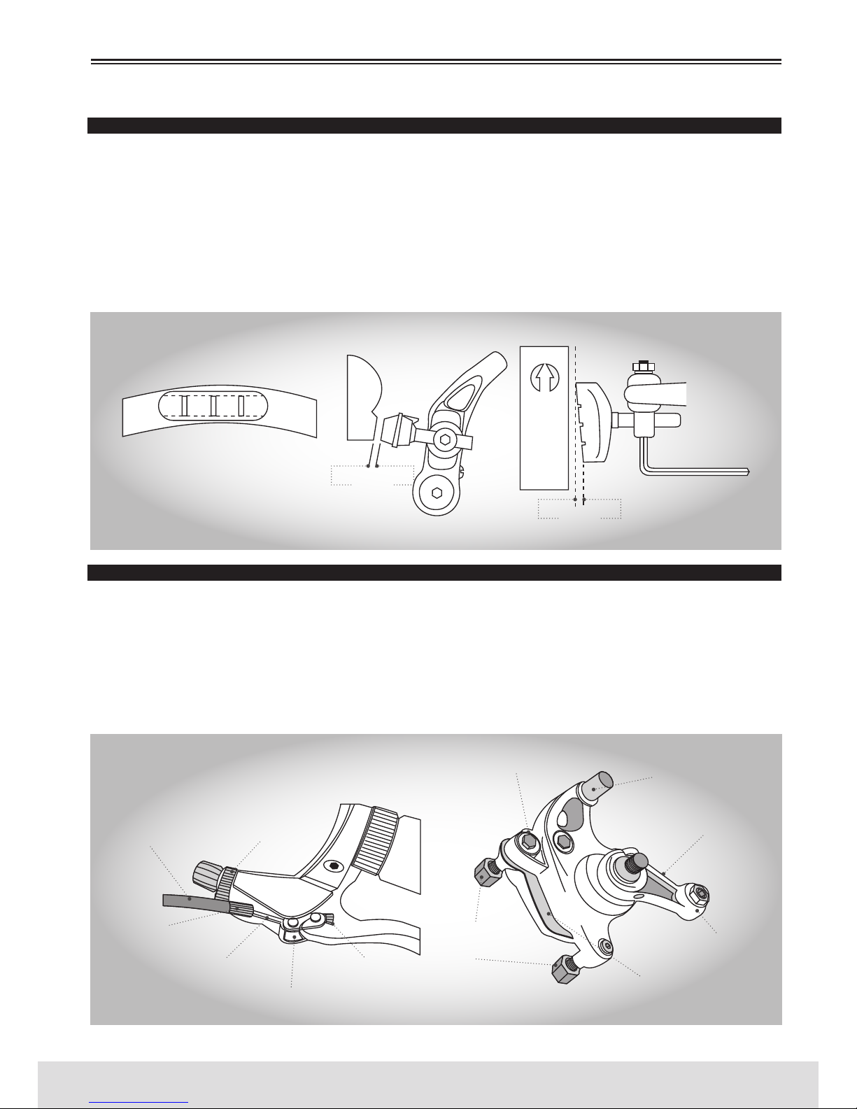
2. While holding the pad against the rim, adjust the grade of protuberance of the pad by inserting the
position of the B washers (i.e. 6 mm and 3 mm) so that the dimension A is kept to 39mm or more.
3. While holding the pad against the rim, tighten
the pad locknut.
5. Calibrate the adjustable spring bolts.
4. Pass the inner cable through the inner Noodle.
Place the cable leaving a space of 1mm between each
brake pad and the rim, tighten the cable locknut.
6. Low the brake lever about 10 times the height of
the wrist, to check that everything is working properly and that the pad clearance is correct before using the brakes.
ASSEMBLY
PAD LOCKNUT
WASHER
6mm B WASHER
3mm B WASHER
A WASHER
39mm OR MORE
A
A WASHER
PAD LOCK
CONNECTION
5mm
ALLEN WRENCH
5mm
ALLEN WRENCH
PAD LOCKNUT
1mm
1mm
2 2 11
1mm
1mm
SPRING TENSION
ADJUSTMENT SCREW
LOWER APPROXIMATELY 10 TIMES
Page 27
27
ENGLISH
www.bergcycles.com
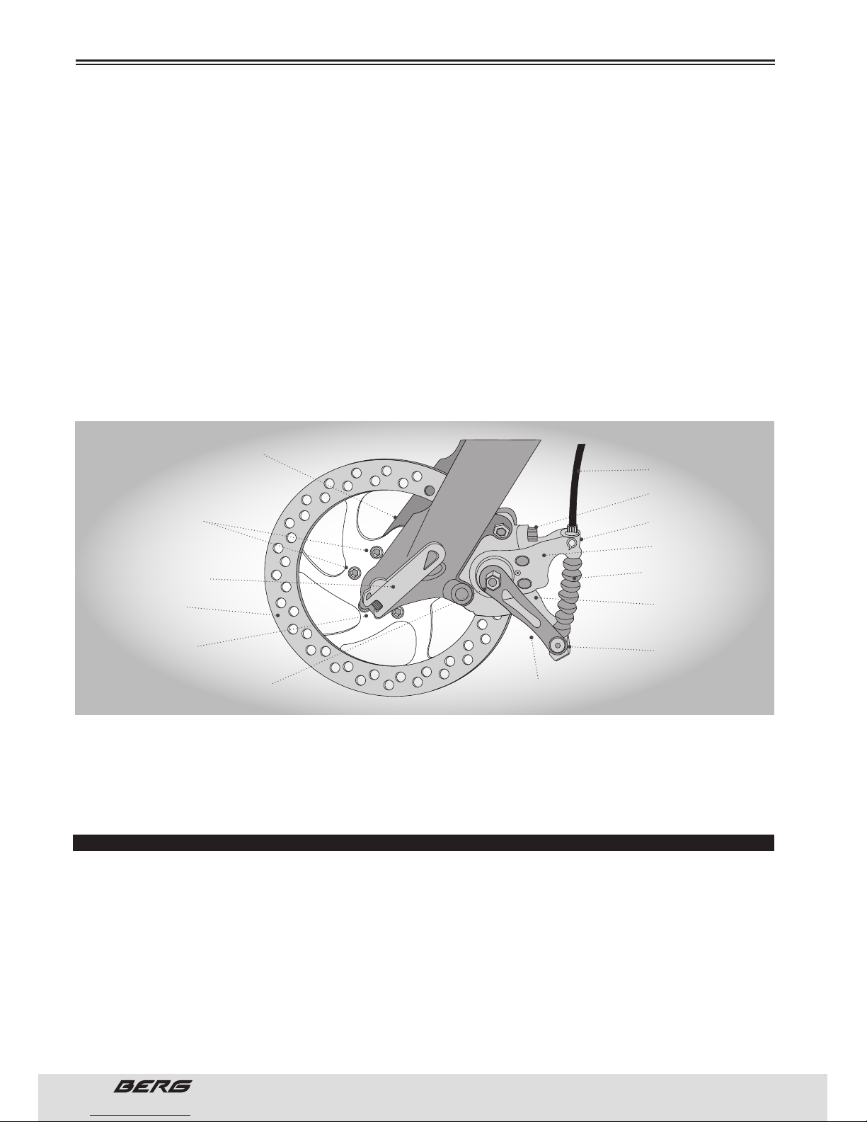
BRAKES INSPECTION
Press the brake levers to make sure they are not stuck and that the brake pads press the hoops hard
enough to stop the bike. “e brake pads must be adjusted to stay 1 to 2 mm away from the rim when
the brakes are not activated”. e brake pads should be centred on the rim and “lean forward” so that the
back of each brake pad is about 0.5 to 1.0 mm away from the rim than the front brake pad.
Do not ride a bicycle until the brakes are working properly. For the test, lock them while pushing the bike
forward to make sure they stop the bike. Never ride a bicycle that does not work properly.
Do not block your brakes. e sudden or excessive use of the front brake may launch the rider onto the
handlebar, causing serious injury or death. When braking, always use the rear brake first, then the front.
DISC BRAKES
If the bike is equipped with a front disc brake, the components should already be placed. However, check
all connections slightly before riding the bicycle. Tighten the 6 screws that hold the disc to the hub of
the front wheel and the two screws that hold their braking mechanism to the fork. Attach the front
wheel between the tips of the fork making sure that the disc fits into the locking mechanism between
the brake pads when they are closed. Connect the front wheel to the bike by pushing the quick-release
mechanism and placing the lever in the closed position. Refer to page 39 for further instructions on the
quick release mechanisms.
ASSEMBLY
0,5/1mm
1/2mm
BRAKE PAD ALIGNED TO THE SURFACE
OF THE RIM
THE PAD AND THE RIM SHOULD
BE PARALLEL
RIM ROTATION DIRECTION
BRAKE
CABLE COIL
TENSOR
CABLE
INSERTION SLOT
BRAKE CABLE
CABLE EXTREMITY
SUPPORT
BRAKE TYPE
SELECTOR
BRAKE LEVER
CALIBRATOR
MOUNTING BOLT
WITH SPACERS
BRAKE PADS
CABLE FIXING BOLT
TIGGER ARM
ROTATION ARM
C CLIP
LOCKNUT
Page 28
28
// USER’S MANUAL
ENGLISH
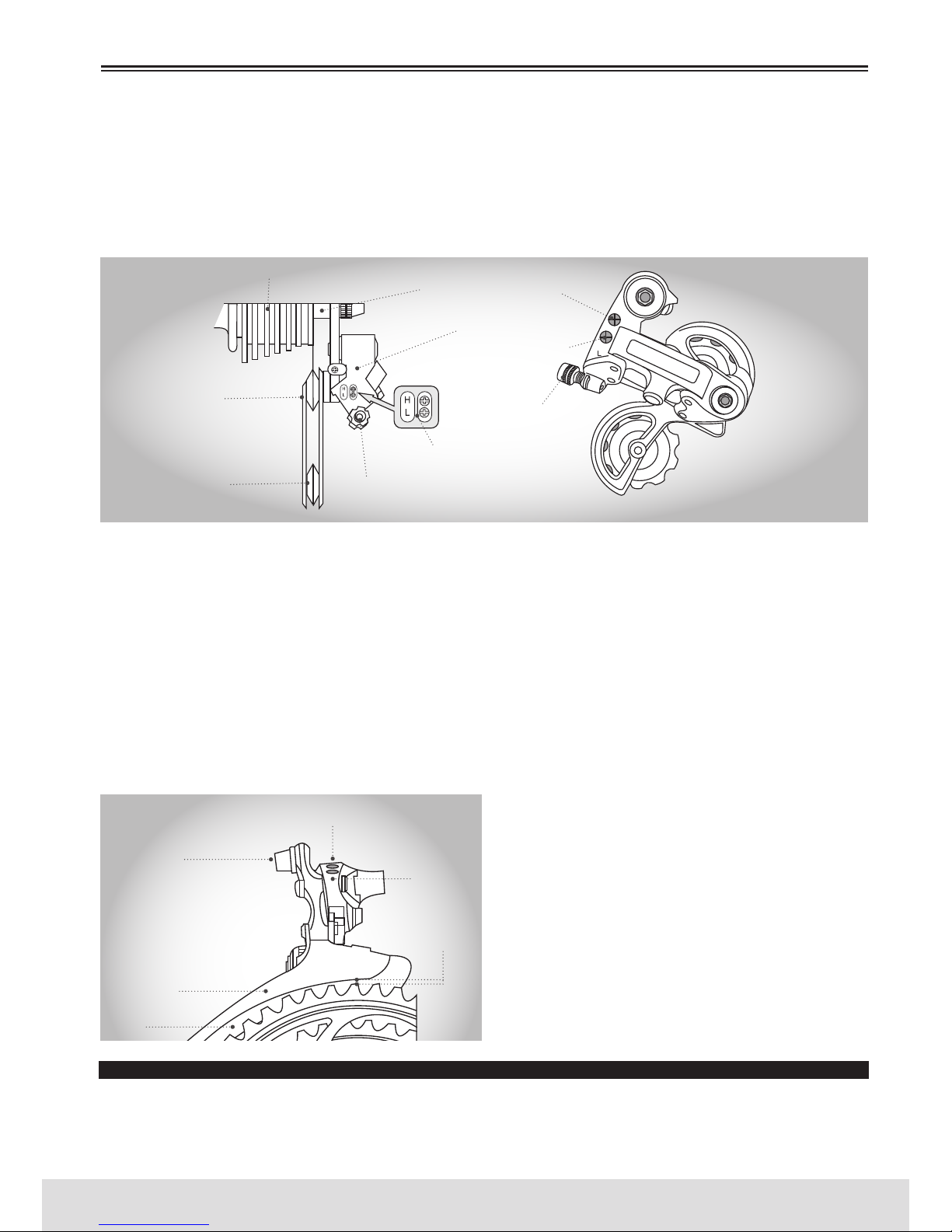
en connect the cable to the brake lever inserting the cable end on the stand after the tensioner and
the slots of the nut are aligned with the support of the end of the cable. After the cable is connected to
the lever, turn the tensor and nut so that the slots no longer align. Make sure that the cable cover rests
properly on the end of the tensor and check for damage.
Slide the exposed brake cable through the rotation bar located in the body of the calibrator and place the
coverage on the same terminal. Insert the cable in the spring and in the spring tab.
en slide the cable through the cable fixator and remove the tension. Hold the cable in place by tightening the screws that compress the assembly of the fixator. Some disc brakes have a centring device
while other mechanisms are free-floating.
If the body of the calibrator is equipped with centring pins, use the brake lever after the cable is connected. While pressing the handle, tighten the centring bolts securely. is will centre the body of the
calibrator over the disc.
DISC GETS HOT! Severe injury could result from contact with the hot disc! Mind your legs, as well as your
hands.
ese brakes require breaking in! Ride and use the brakes gently for 13 miles before using the brakes
in downhill conditions, for sudden stops, or any other serious braking. Please be aware that your brake
system will change in performance throughout the wear-in process. e disc brake should be cleaned
before the first ride using rubbing alcohol. NEVER use oil or similar products to clean your disc brake
system.
DERAILLEUR
Although the front and rear derailleurs are initially adjusted at the factory, you will need to inspect and
readjust both before riding the bicycle.
REAR DERAILLEUR
Begin by shifting the rear shifter to largest number indicated and place the chain on the smallest sprocket. Adjust the High limit screw so the guide pulley and the smallest sprocket are lined up vertically.
Reconnect the cable, pull out any slack, and retighten the anchor bolt securely. Shift through the gears,
making sure each gear achieved is done quietly and without hesitation. If necessary, use the barrel
adjuster to fine tune each gear by turning it the direction you want the chain to go. For example, turning
clockwise will loosen the cable tension and move the chain away from the wheel, while turning coun-
ASSEMBLY
QUICK RELEASE
LEVER
DISC MOUTING
BOLTS
BRAKE CABLE
COVER
CENTRING PIN
ROTATION BAR
CALIBRATOR
BODY
CABLE BOOT WITH
SPRING INSIDE
CENTRING PIN
(INTERIOR)
CABLE FIXING
BOLT
TRIGGER ARM
HUB
FORK LEG
DISC
FORK
DROPOUTS
CALIBRATOR MOUNTING
BOLT WITH SPACERS
Page 29
29
ENGLISH
www.bergcycles.com
ter-clockwise will tighten cable tension and direct the chain towards the wheel. Shift the rear shifter to
the gear one and place the chain on the largest cog. Adjust the Low limit screw in quarter turn increments
until the guide pulley and the largest cog are aligned vertically. Again, shift through each gear several
times, checking that each gear is achieved smoothly. It may take several attempts before the rear derailleur and cable is adjusted properly.
Ensure all bolts are secured tightly and the chain does not fall off in either direction.
FRONT DERAILLEUR
Shift both shifters to the smallest number indicated and place the chain on the corresponding cog and
chainwheel. Disconnect the front derailleur cable from the cable anchor bolt. Check the position of the
front derailleur; it should be parallel with the outer chainwheel and clear the largest chainwheel by
1-3mm when fully engaged. With the chain on the smallest chainwheel in front and the largest cog in
back, adjust the Low limit screw so the chain is centred in the front derailleur cage. Reconnect the cable,
pull any slack out, and tighten the anchor bolt securely. Shift the front shifter to the largest chainwheel. If
the chain does not go onto the largest chainwheel, turn the high limit screw in 1/4 turn increments counter-clockwise until the chain engages the largest chainwheel. If the chain falls off the largest chainwheel,
and into the pedals, you will need to turn the High limit screw in 1/4 turn increments clockwise until the
chain no longer falls off. Shift through every gear, using the barrel adjusters to fine tune each transition.
e barrel adjuster for the front derailleur is located on the front shifter where the cable comes out of
the shifter. Clockwise will loosen the cable tension
and direct the chain closer to the frame while counter-clockwise will tighten the cable tension and di-
rect the chain away from the frame.
Do not ride a bicycle that is not shifting properly.
Overlooking proper adjustments may cause irreparable damage to the bicycle and/or bodily injury.
Never move the shifter while pedalling standing
up, or under heavy load, nor pedal backwards after
having moved the shifter. is could jam the chain
and cause serious damage to the bicycle and/or
rider.
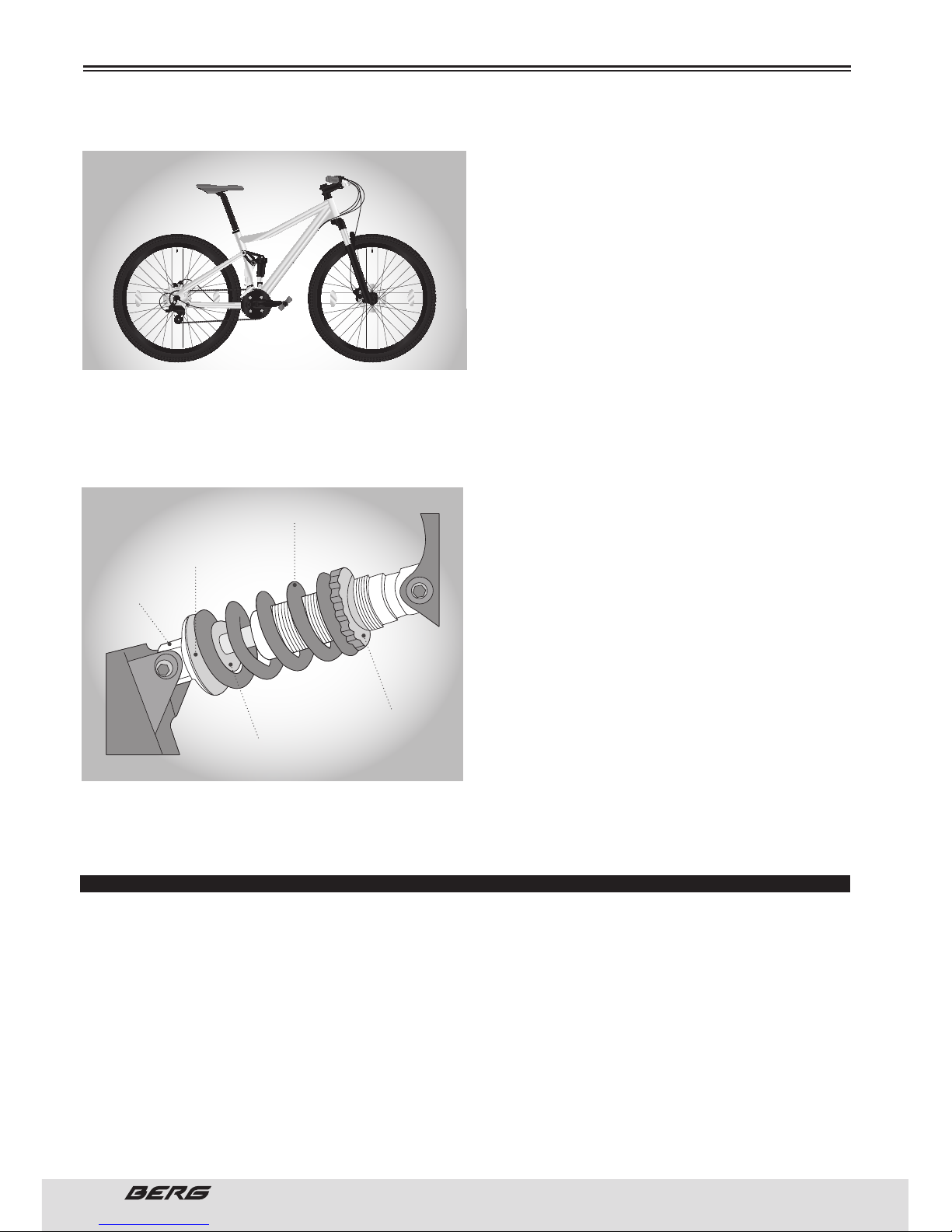
DUAL SUSPENSION
e bikes with dual suspension (DS) are equipped with a fork in addition to a rear suspension usually
located under the saddle. e piston works in combination with a spring to allow the bike to run on a
ASSEMBLY
FREEWHEEL OUTSIDE OF THE UPPER
SPROCKET
PULLEY ADJUSTMENT
BOLT
UPPER SPROCKET
ADJUSTMENT BOLT
UNDER SPROCKET
ADJUSTMENT BOLT
TENSOR
REAR DERAILLEUR
SIDE VIEW
SIS CABLE
REGULATOR
ADJUSTMENT
BOLTS
GUIDE PULLEY
TENSION PULLEY
LOWER ADJUSTMENT
BOLT
CABLE ANCHOR
GUIDE
UPPER
ADJUSTMENT
BOLT
CHAIN GUIDE
FREE SPACE
OF 1-3mm
EXTERNAL CHAIN
GUIDE
INTERNAL CHAIN
PROTECTION
Page 30
30
// USER’S MANUAL
ENGLISH
pivot point. Make sure that all fasteners are tight and there is no lateral movement in the rear triangle.
e degree of displacement of the rear suspension
can be adjusted by turning the adjustment plate.
Turning in a clockwise direction, the spring tension will increase and will reduce the displacement, while rotating in the opposite direction the
spring tension will decrease and increase the displacement. ere are many types of suspension
systems, too many to be treated individually in
this manual. ere must be enough tension in the
spring to hold the spring plate in place. If not, it
is possible that the mechanism fails. If the suspension system is not maintained, inspected and adjusted as appropriate, may malfunction, this may
cause you to lose control and fall. Changing the suspension settings can modify the characteristics of
handling and braking of the bike. Never change the settings of suspension unless you have an extensive
knowledge of the suspension system, instructions and manufacturer’s recommendations, inspect the
bike behaviour with the changes when the bike rides through a careful experimentation, on an area free
of hazards. If your bicycle has a suspension kit,
and you want to increase speed, remember that it
will also increase the risks. When braking, the bike
front suspension will low.
You may lose control and fall if you don’t have the
capacity to handle with this system. Learn to han-
dle the suspension system safely before downhill
at high speed.
If your bike is equipped with an air damper you
should consult the manufacturer’s manual ( if it
exists). For more information on the functioning
and pressure contact the Berg Cycles Technical De-
partment.
Never forget the periodic reviews of your shocker.
Do not use your bike if the shock pressure is not
correct. You may lose confidence in using / seriously compromise the functioning.
For more information please consult page 56 to 57.
FINAL INSPECTION
After making all adjustments, place all the gears several times at different speeds. is will ensure that
all settings are correct allowing you to locate any problematic areas. If you have any problems, consult
the appropriate section and make the necessary adjustments.
Check the tire pressure and fill each chamber as recommended (pounds per square inch = psi), as established in the tire. Make sure the stand works smoothly and if the screw is tightened.
Finally, examine the bike. Make sure that all accessories are placed and all quick release levers, nuts
and bolts are tightened.
Proper maintenance of your bike guarantees years of enjoyable rides.
Perform maintenance to your bike regularly reviewing the relevant sections of this manual, or taking it
to a bike shop where you can consult professionals technicians.
Always wear a helmet and obey all traffic regulations.
ASSEMBLY
SPRING
SPRING PLATE
PISTON
ADJUSTMENT
PLATE
FIXATION
BOLT
Page 31
31
ENGLISH
www.bergcycles.com
Never inflate a tire beyond of the maximum pressure marked on the side of it.
If you exceed the recommended pressure, the tire can explode and leave the ring, causing damage to the
bike and injuries to the rider injuries and pedestrians”
Tighten the nuts of the rear wheel axle or the quick release mechanism securely. If you do not, the rear
wheel may leave the frame dropouts causing damage and serious injuries.
CHILD AND BMX
Includes 12”, 14”, 16”, 20” and 24” BMX bikes. e assembly is similar to the man and woman bikes.
Prologue: e assembly of a bicycle is a very important responsibility. e proper assembly not only
makes the rider more enjoyment of cycling, but also represents an important safety measure.
Getting started:
Open the cardboard box at the top and take the bike out. Remove the buckles and the protection. Inspect
the bike and all accessories and parts in search of missing pieces. It is recommended to grease the nuts
and all moving parts prior to installation. Do not throw away packaging materials before finalizing the
assembly to make you do not lay out necessary parts accidentally. Assemble the bike following the steps
relating to your model.
e bike can be equipped with components with different styles from those illustrated.
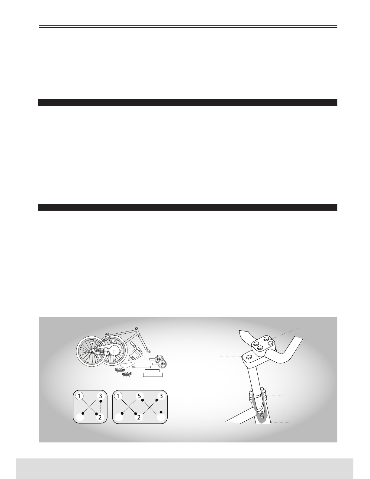
HANDLEBAR
Remove the protective cover of the stem wedge and loosen the screw with a 6mm Allen wrench. Some
models can use a 13mm hexagonal screw, instead of an Allen screw. Place the stem on the handlebar
tube, observing the minimum insertion mark of the stem and making sure that all cables are free of
obstruction.
Make sure the fork and handlebar are facing forward and that they are correctly aligned with the front
wheel. Tighten the stem cover bolt. Turn the handlebar to the desired position. Tighten the stem cover
(see diagram) with two turns, tighten the screw cap 2 and so successively. Repeat until the handlebar
holds on to the stem. See diagram for the 4 or 6 system screws. Also make sure that the stem screws
are similarly attached and secure.
e handlebar must be inserted so that the minimum insertion mark cannot be seen. If the stem bolt or
the steering set are too tight, may result in damage to the bicycle and / or injury to the cyclist.
ASSEMBLY
4 BOLTS FRONT
PLATE
6 BOLTS FRONT
PLATE
STEERING TUBE
STEM WEDGE
MINIMUM INSERTION
MARK
STEM BOLT
STEM COVER BOLTS
Page 32
32
// USER’S MANUAL
ENGLISH
ASSEMBLY
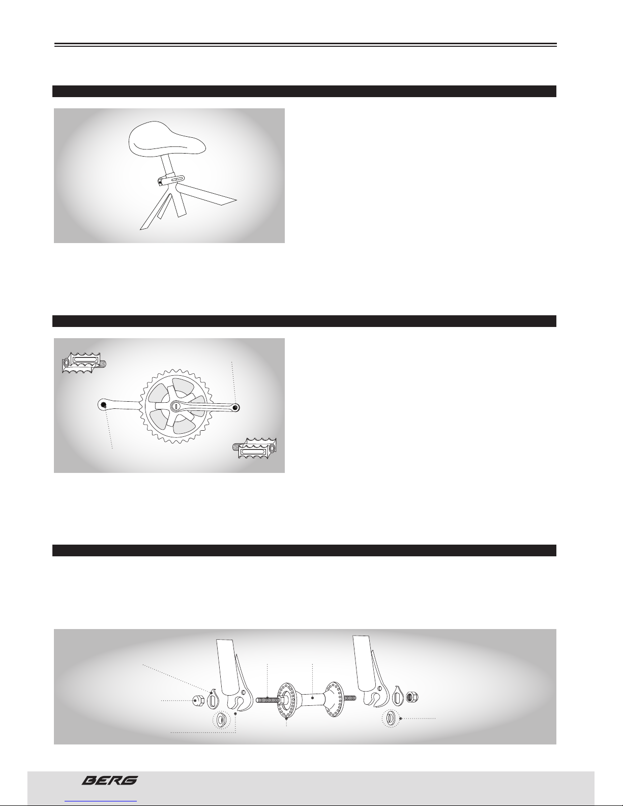
SADDLE
Unscrew the nut on the seat clamp and place 3 or 4
drops of oil on the threaded screw. Place the smaller
end of the saddle seatpost on the seatpost clamp until
it holds with the screw facing the back of the seat tube.
Screw the nut on the clamp without tightening it. Insert
the larger end of the saddle seatpost in the frame saddle tube, watching the minimum insertion mark on the
seatpost saddle. Place the top of the saddle so that it
becomes parallel to the ground. e toothed parts from
the saddle clamp should dock altogether with the ones
on the saddle frame; push the front of the saddle up and down to align the teeth. Securely tighten the
saddle clamp. Tighten the screws on the seatpost saddle clamp strongly. Place the bike upside down and
support it over the saddle and handlebar. e seat post must be inserted so that the minimum insertion
mark cannot be seen. Check in accordance with page 16.
PEDALS AND CRANKS
Look for the letters “R” for right, and “L” for left, stamped
on each pedal spindle. Start each pedal spindle by hand
to avoid stripping the threads. (Note that the right hand
pedal attaches to the chainwheel side crank arm with a
right-hand (clockwise) thread. e left pedal attaches to
the other crank arm and has a left hand (counter-clock-
wise thread). Tighten with a 15mm narrow open ended
wrench. It is very important that you check the crank
set for correct adjustment and tightness before riding
your bicycle. e new brackets can loosen with the initial use, consult pages 45 to 46 for information about proper setting and maintenance of the brackets
set. After being locked to the pedals, make sure the bracket rotates smoothly and that there is no lateral
movement. Attachment of an incorrect pedal into a crank arm can strip pedal threads and cause irreparable damage. Before your first ride, please check to ensure your pedals are attached correctly.
FRONT WHEEL
1. Make sure that the brakes are loose enough to allow the wheel to pass through the pads easily.
2. Place the front wheel between the tips of the fork.
3. Install the retention rings with raised edges pointing to the fork and insert them on the small hole in
the leg of the fork.
ONLY ATTACH THE LEFT PEDAL
ONLY ATTACH THE RIGHT PEDAL
IMPORTANT!
IMPORTANT!
AXLE HUB
PROGRESSIVE RETENTION
WASHER
CONIC NUTS
FORK DROPOUTS
AXEL NUT
RETENTION WASHER
Page 33
33
ENGLISH
www.bergcycles.com
Some bikes may have progressive retention washers instead of the retention washer (drawn with a
dashed outline). If so, install the retention washer with raised part gradually sliding it between the legs
of the fork.
4. Put the axle nut and tighten. Make sure that the wheel is centred between the legs of the fork.
5. Spin the wheel to make sure it is centred and does not clash on the brake pads.
Squeeze the brakes if necessary.
6. Put the bike in an upright position using the stand for support.
It is very important to inspect the front wheel of the bike. If not tightened properly, it is possible that the
front wheel can break loose.
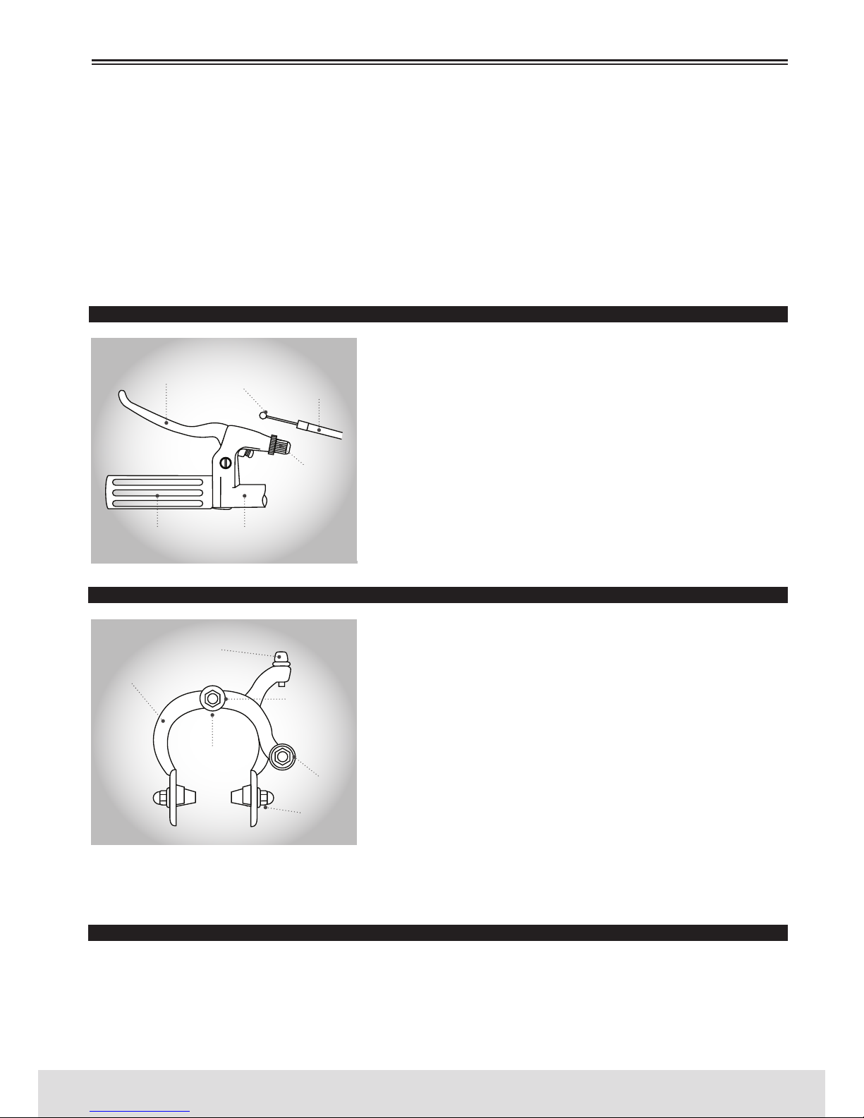
FRONT BRAKE
Determine which type of brake your bike is equipped with and
refer to the appropriate assembly instructions, page 25 to 28.
A larger force is needed to activate the rear brake due to cable length. It is recommended to mount the rear brake on the
side of the hand that has more strength. It is important to familiarize yourself with the use of hand brakes. When adjusted
properly, these brakes are an efficient braking system. Always
keep the rim and the brake pads clean and free of wax, grease
or dirt. Keep the brakes properly adjusted and in good working
condition.Open the brake lever and place the cable terminal tip
in the short brake lever , and then close it. Hold the brake cable
against the lever with the cable adjustment barrel.
SIDE BRAKE
Unscrew the nut of the cable and insert the brake cable through
it. Tighten the nut by hand until you put the cable in place.
Squeeze the brake arms at the same time, against the wheel
rim. Loosen the nuts of the brake pads and rotate them until
they match the rim angle.
Tighten the nuts firmly. Pull the tip of the brake cable in the a
clamp, maintain a good grip and tighten the nut of the cable
securely. Spin the wheel, the brake pads should not touch the
rim at any point and must be at the same distance on both
sides. Make sure that all nuts and bolts are securely tightened.
Test the brake levers from 20 to 25 times in order to observe
any initial cable stretch. Make sure to tighten the nut behind
the brake fork.
To assemble or adjust the brakes, make sure that the fastener of the cable is stiff. If the nut is not tightened securely, it may cause a brake failure and, consequently, injuries.
V-BRAKES
1. If your bike is equipped with V-brakes, insert the brake body into the centre hole of the spring in the
hub assembly of the frame and then secure the brake body to the chassis with the screw.
2. While holding the pad against the rim, adjust the degree of protuberance of the pad, alternating the
position of the B washers (6 mm or 3 mm) so that the dimension A is kept to 39mm or more.
ASSEMBLY
CABLE ADJUSTMENT
BARREL
CABLE ADJUSTMENT
BARREL
HANDLEBARGRIP
CABLE FIXING
BOLT
BRAKE
PAD
BRAKE ARM
BRAKE LEVER
CABLE TERMINAL
BRAKE CABLE
FIXING BOLT
REAR
CENTER BOLT
Page 34
34
// USER’S MANUAL
ENGLISH
3. While holding the pad against the rim, tighten the retention nut.
4. Pass the inner cable through the inner cable lead. Place the cable with clearance of 1mm between each
brake pad and rim, tighten the cable fixing bolt unit.
5. Calibrate with the spring tension screw adjustment.
6. Lower the brake lever about 10 times the height of the wrist, to check that everything works properly
and that the pad clearance is correct before using the brakes.
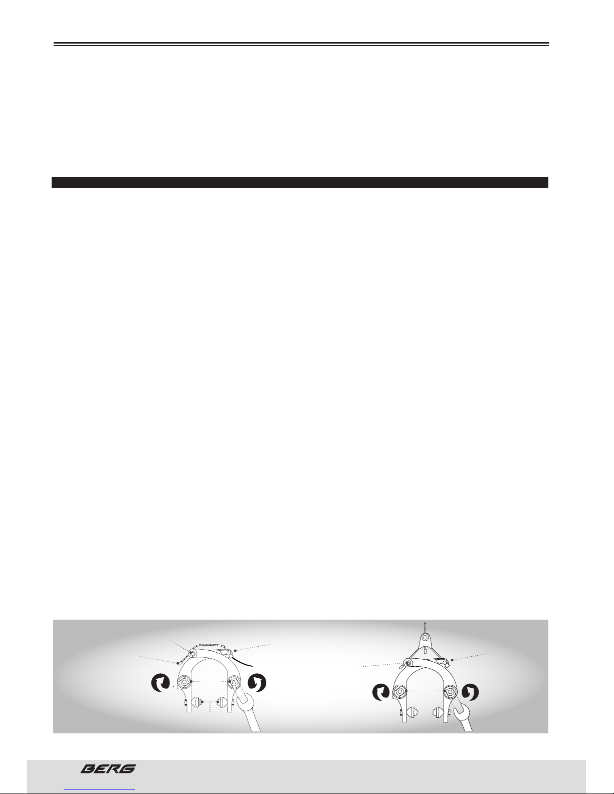
U BRAKES
Start by adjusting the U brake pads with a 10mm wrench. Make sure that the pad touches the rim and
not the tire. Ideally, the front of the pad should touch the rim approximately 1 mm before the rear pad.
U FRONT BRAKE
Slide the cable and cover of the brake through the brake drum and the cable fixing bolt. Establish a 1mm
clear space for the cable between the brake pads and rim. Tighten the cable fixing bolt unit. To follow the
illustrated instructions, look at the bike forward. To adjust the brakes use a 13mm combination wrench
and a 5mm Allen wrench. Loosen the Allen bolt 5mm. Turn the spring tension nut with a 13mm combination wrench counter clockwise to the side of the sprockets (left) side of the bike to increase spring
tension.
Turn the spring tension nut with a combination wrench in a clockwise direction, to the side where they
are not sprockets (right), to increase spring tension. When you have the desired tension, hold the tension
nut with the 13mm wrench to tighten the 5mm Allen screw. e tension on each side must be the same
so that the brake arms move the same distance when the brake is activated.
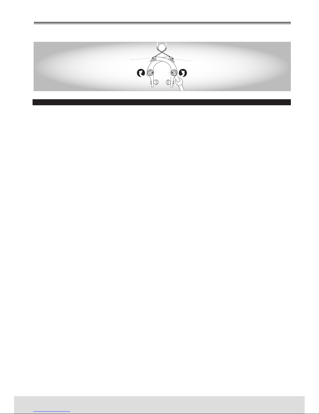
U REAR BRAKE
Option 1: Tighten the cable carrier to the brake cable approximately 20mm from the brake arms. When
they are tight against the rim, tighten the brake cable to the carrier. Attach the cable end into the slot
of the brake, pull the excess cable through the cable holder and tighten the cable fixator. Continue with
part “For both options” below.
Option 2: Put the brakes coverage on the frame coverage cover blockers. Pull the brake cable so that
it becomes stiff and pass it through the fixation screw of the opposite cable. Tighten the cable. Repeat
for the other side. Continue with part “ for the two options” For two options: To adjust the brakes, use
a 13mm combination wrench and a 5mm Allen wrench and loosen the Allen screw 5mm , to the side of
the bike sprockets (right), turn the spring tension nut with a 13mm combination wrench counter clockwise to increase the spring tension”, to the side where there are not sprockets (left), turn the spring
tension nut with a combination wrench in clockwise direction to increase spring tension. When you have
the desired tension, hold the tension nut with the 13mm wrench to tighten the 5mm Allen screw. e
tension on each side must be the same so that the brake arms move the same distance when the brake
is activated.
PLEASE NOTE that some BMX frames have U brakes directed and assembled under the risers. e direction to tighten the springs will be oriented the same way as illustrated.
ASSEMBLY
BRAKE CABLE
BRAKE CABLEREAR U BRAKE
OPTION 1
FRONT U BRAKE
BRAKE BARREL
ATTACH THE CABLE
TERMINAL
BRAKE
PADS
5mm
ALLEN
BOLT
5mm
ALLEN
BOLT
CABLE RETENTION
SCREW
CABLE FIXATOR
BIFURCATED CABLE
BRAKE
CABLE CARRIER
CABLE TERMINAL
TO TIGHTEN
THE SPRING
TO TIGHTEN
THE SPRING
TO TIGHTEN
THE SPRING
TO TIGHTEN
THE SPRING
SPRING
TENSION NUT
SPRING
TENSION NUT
SPRING
TENSION NUT
SPRING
TENSION NUT
Page 35
35
ENGLISH
www.bergcycles.com
INSPECT THE BRAKES
Press the brake levers to make sure they do not lock and the brake pads press the rims with sufficient
force to stop the bike. e brake pads should adjust so that they are at 1 or 2 mm away from the rim
when the brakes are not activated. e brake pads should focus on the rim and back of each brake coverage pad should be approximately 0.5 to 1.0mm furthest from to rim to the front.
Do not ride a bicycle until the brakes function properly. For the test, apply the brakes while pushing the
bike forward, making sure that they hold.
ROTORS
Some freestyle BMX bikes are equipped with a system that allows the handlebar to turn 360 degrees
without locking the cables. It is very important that this system is adjusted properly. e installation
should only be performed by a qualified bicycle mechanic, and with the right tools.
UPPER CABLE
1. First connect to end of the cable drum above the rear brake lever.
Make sure that the long cable coverage is over the short cable coverage, otherwise the top cable will be
twisted more in him.
2. Pass the upper cable through the handlebar (under the bar) with the short cable coverage, on the the
same side as the rear brake lever.
3. Connect the upper cable to the top plate through the upper cable cap nuts upper through the holes of
the top plate and connecting them to the bearing.
4. Screw the stretch drums on the top plate. Do not tighten the nuts at this time.
BOTTOM CABLE
1. Slide the cable spiral through the Noodle on the frame.
2. Connect the lower cable to the bottom plate through the cap nuts of the lower cable through the
threaded holes on the bottom plate and connecting them to the bearing.
3. Screw the stretch drums on the bottom plate. Do not tighten the nuts at this time.
4. Connect the lower cable to the rear brake. Do not tighten the rear brake at this time.
Make sure that all edges of the tube cable spiral from the upper and lower cables are correctly seated
and that the spring tension on the rear brake is pushing the bearing down.
SETTINGS
1. Screw the cable adjuster to the rear brake lever and the upper cable splitter altogether.
2. Screw the stretch drums into the top plate (or out) to adjust the bearing to obtain the maximum displacement. e bearing should be as low as possible without being supported on the bottom plate or on
the stretch drum bolted on the bottom plate.
3. Use the stretch drums screwed on the upper plate to put the bearing in a parallel direction to the upper
plate. Use a 10mm screwdriver to tighten the 10mm nut on the upper left stretch drum. Do not tighten
ASSEMBLY
BRAKE CASING
REAR U BRAKE
OPTION 2
BRAKE CABLE
5mm
ALLEN
BOLT
CABLE FIXATOR
CABLE BRAKE
FRAME COVERAGE BLOCKERS
TO TIGHTEN
THE SPRING
TO TIGHTEN
THE SPRING
SPRING
TENSION NUT
SPRING
TENSION NUT
CABLE FIXATOR
Page 36
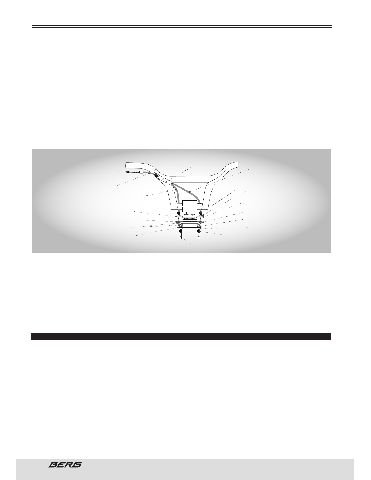
36
// USER’S MANUAL
ENGLISH
the right stretch drum.
4. Screw the lower cable stretch barrel on the (or off) bottom plate until it is as close as possible to the
bearing, without touching it.
5. Screw the cable regulator to the upper cable splitter to eliminate all the tension. en screw the cable
adjuster once again to raise the bearing 1mm more on the opposite direction of the lower handle stretch
drums.
Do not screw the cable adjuster on the upper cable splitter more than 8mm. Use the rear brake lever
cable adjuster if you need a higher setting.
6. Check the bearing noise by placing the handlebar to its normal direction, then rotating it rapidly back
and forth. Follow the steps below to eliminate bearing noise.
You never should allow the bearing to rest on the bottom plate or on the stretch drums of the lower cable.
a) Screw the lower cable stretch drums out (or inside) of the bottom plate to eliminate any noise generated by the bearing.
b) Tighten the right stretch drum lock nut to the lower cable.
c) Turn the handlebar 180 degrees and recheck the bearing noise. If the bearing produces some noises,
use the stretch drums “loose” over the cables on the top and bottom to eliminate it.
d) Repeat steps (6a) and (6c) until the handlebar can rotate 360 degrees without the bearing producing
noises.
e) Finish tightening the rear brakes.
INSTRUCTION FOR ASSEMBLY THE FOOT PLATE
THREADLESS
First remove the axle nut. You will find a washer or a progressive retention washer. Locate the washer
between the foot plate and the bike frame.
Slide the foot plate on the shaft, followed by a flat washer and finally the axle nut. Tighten the shaft in
clockwise direction until the foot plate is fully tighten against the frame or fork. Repeat for all the remaining foot plates.
THREADED
is type of foot aplates coiled up to fit the axle. Make sure that the axle nut is tightened with a 15mm
wrench. Place a screw through the mounting holes of the foot plates and tighten the shaft rotating in
a clockwise direction. Press against the frame or fork to get a perfect fit. Repeat for all the remaining
foot plates.
ASSEMBLY
BARREL
EXTREMITY
INDIVIDUAL CABLE
COATING
UPPER CABLE
(LONG COATING)
UPPER CABLE
(SHORT COATING)
CABLE REGULATOR
CABLE DIVISOR
UPPER PLATE
BEARING
CAP NUTS
LOWER PLATE
BOTTOM CABLE
STRETCHING BARREL
STRETCHING BARREL
LOCKNUT
1mm (1/32.) MINIMUM
WASHER WITH BRACE
LOCKNUT
ADJUST FOR MAXIMUM
DISPLACEMENT
Page 37
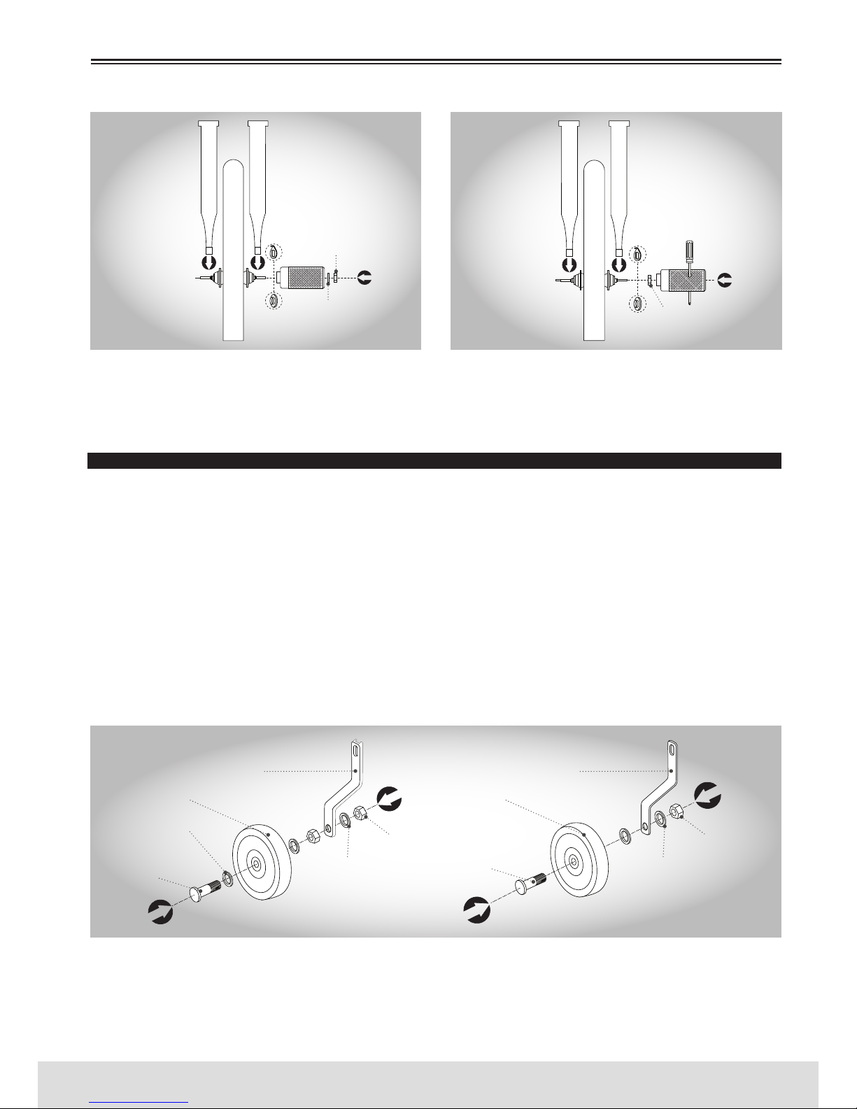
37
ENGLISH
www.bergcycles.com
Not all axles can carry foot plates. Consult our local Distributor service if you want to clarify any doubt.
Some BMX bikes come with two or four foot plates. If your bike is a Dirt Jump bike you may receive only
two foot plates. ese are designed for one side only. e Freestyle bikes may come with four foot plates,
two for each wheel. Dirt Jump bikes usually do not come with foot plates.
TRAINING WHEELS
ere are two different braces used to attach the training wheels to the bicycle. Determine which brace
was included with your bicycle and follow the given instructions for that particular brace.
OPTION 1 - First tighten the training wheels to the wheel support. Place a washer on the rebound bolt.
en, insert the rebound bolt trough the wheel. Place another flat washer and screw a hexagonal nut on
the rebound bolt. Insert the rebound bolt through the wheel support and place a washer on the rebound
bolt. Repeat the procedure for the other wheel.
OPTION 2 - First tighten the training wheels to the wheel support. Insert the rebound bolt trough the
wheel. en place a fat washer. Insert the rebound bolt through the wheel support and place a washer on
the rebound bolt. Tighten the training wheel in place by screwing another hexagonal nut on the rebound
bolt. Repeat the procedure for the other wheel.
It is very important to check the training wheel connection to the bicycle. Failure to properly tighten may
cause the training wheel to dislodge. Please contact the local distributor with any questions.
ATTACHING TRAINING WHEEL BRACE TO BICYCLE
ere are two different braces used to attach the training wheels to the bicycle: the c-shape brace and
the flat brace. Determine which brace was included with your bicycle and follow the given instructions
for that particular brace.
ASSEMBLY
THREADLESS THREADED
FRONT/REAR
RETENTION TIPS
FRONT/REAR
RETENTION TIPS
RETENTION
WASHER
RETENTION
WASHER
PROGRESSIVE
RETENTION WASHER
PROGRESSIVE
RETENTION WASHER
AXEL NUTS
WASHER
AXEL NUTS
FRONT/REAR
HUBS
FRONT/REAR
HUBS
OPTION 1 OPTION 2
WHEEL SUPPORT WHEEL SUPPORT
TRAINING WHEEL TRAINING WHEEL
WASHER
REBOUND
BOLT
REBOUND
BOLT
WASHER WASHER
HEXAGONAL
NUT
HEXAGONAL
NUT
Page 38
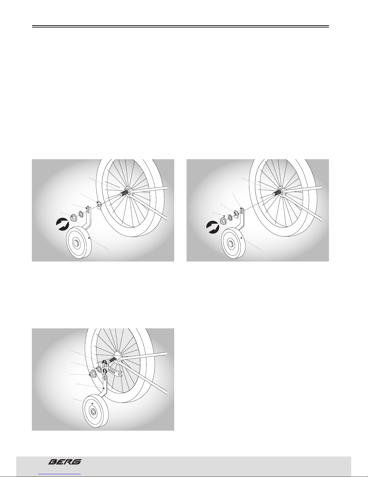
38
// USER’S MANUAL
ENGLISH
ASSEMBLY
C-SHAPE BRACE
Remove the outer axle nut and washer from the rear wheel axle. Place the brace stabilizer washer onto
the axle and align the washer so that the notch on the washer fits into the rear frame drop out. Next,
place the C-shaped wheel brace onto the axle and replace the washer and axle nut. Tighten the axle nut
securely, making sure that the wheel brace stays in the proper vertical position. e elongated hole on
the Wheel brace allows the training wheel height to be adjusted for proper fit.
FLAT BRACE
Remove the outer axle nut and washer from the rear wheel axle. Place the flat Wheel brace onto the axle.
Next place the brace stabilizer washer onto the axle and align it so that the notch fits into the rear frame
drop out. Replace the washer and axle nut. Tighten the axle nut securely, making sure that the wheel
brace stays in the proper vertical position. e elongated hole on the wheel brace allows the training
Wheel height to be adjusted for proper fit.
TRAINING WHEEL STABILIZER BRACKET
Your bike may include a stabilizer bracket to fasten the training wheel to the bike.
Remove the outer axle nut and washer from the rear wheel axle. Insert the wheel brace into the stabilizer bracket so that the forked end of the stabilizer bracket faces in. Slide assembly onto the rear axle
so that the forked end hooks around the chain stay of the bicycle. Replace the axle nut and washer,
secure tightly. e elongated hole on the brace allows for raising and lowering the training wheel to the
proper height.
Not all bicycles will accept training wheels. If your
bike did not come stock with training wheels, please
call our local Distributor service to help determine if
after-market training wheels can be attached.
It is very important to check the training wheel connection to the bicycle. Failure to properly tighten may
cause the training wheel to dislodge. Please contact
the local distributor with any questions.
INTERNAL AXLE
INTERNAL AXLE NUT
DO NOT REMOVE
INTERNAL AXLE
INTERNAL AXLE NUT
DO NOT REMOVE
SUPPORT STABILIZER
WASHER
WHEEL FLAT
SUPPORT
WHEEL C SHAPED
SUPPORT
SUPPORT STABILIZER
WASHER
AXEL NUT AXEL NUT
TRAINING WHEEL TRAINING WHEEL
C SHAPE OPTION FLAT OPTION
WASHER
AXEL NUT
STABILIZER
HOLDER
WHEEL HOLDER
TRAINING WHEEL
Page 39
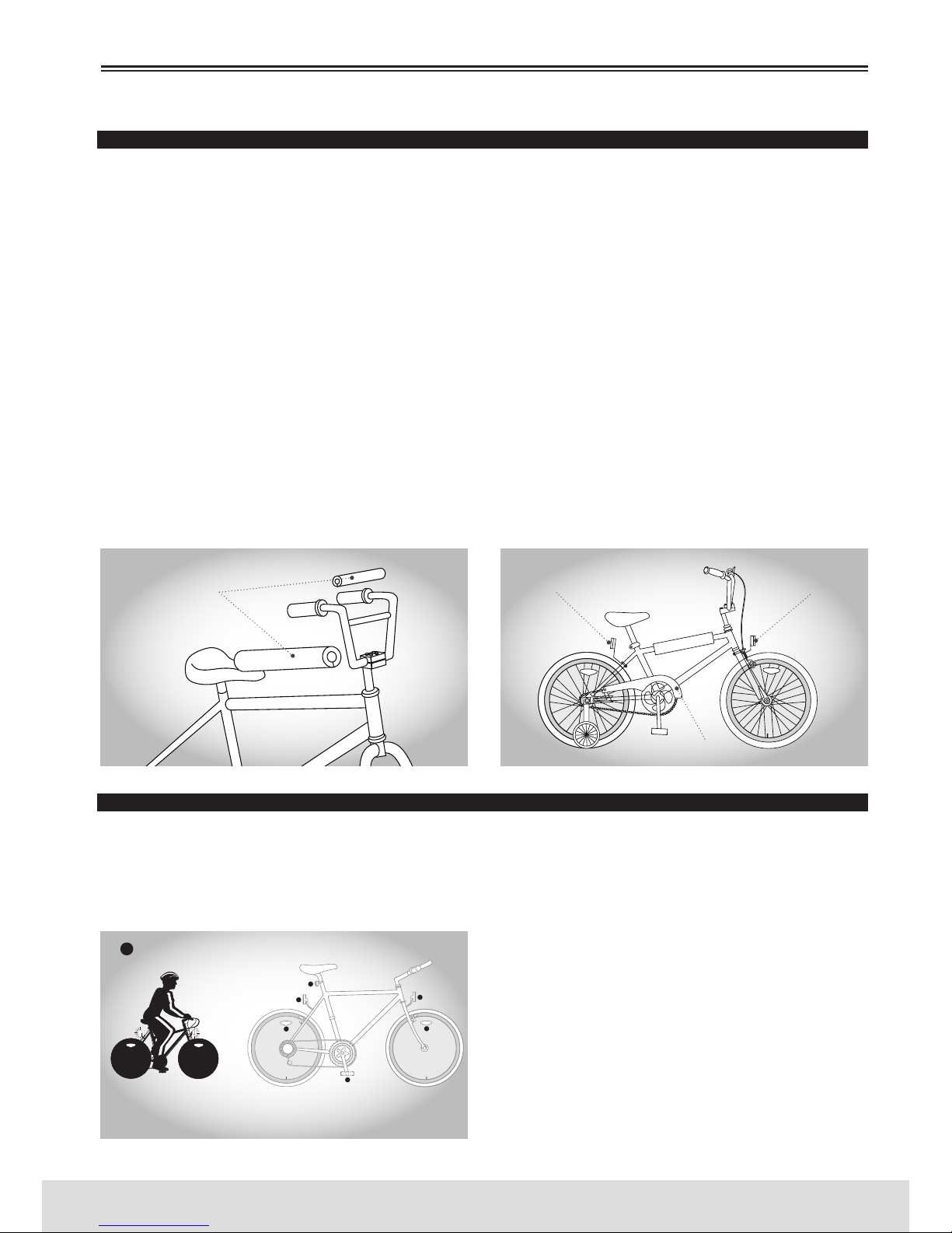
39
ENGLISH
www.bergcycles.com
ASSEMBLY
FINAL CHECK
Install any additional parts that came with your bike.
It is possible that your bicycle is equipped with different style components from the illustrated.
REFLECTORS - Tighten the white reflector to frontal support and red reflector to the rear bracket with an
8mm screwdriver or a Philips screwdriver. Tighten the brackets to the bike with the bolts and nuts provided. In some models, the front reflector bracket should be mounted on the mounting bolt of the front
brake, which arises through the fork. It is very important to make sure that all connections are tightened
securely and that the reflectors are oriented adequately
PROTECTORS - If your bike is equipped with protectors, wrap the protective foam in its interior, around
the bike. Place a protective outer coating over the inside and attach Velcro straps, pressing them firmly.
Turn the protector so that the Velcro strips are facing downward.
CHAINCOVER - If not already in place. Place the chaincover on the bike frame using the brackets provided.
Put it in place taking into account that this should not touch in the chain.
TIRE PRESSURE - Check the tire pressure and inflate each tube to the recommended psi as stated on the
sidewall of the tire.
BOLTS - ere are too many different types of bolts, so it is impossible to mention them individually in
this manual. Consult your dealer for specific information related to the bolts installation.
Finally, examine the bicycle. Make sure all accessories are attached and all quick releases, nuts and bolts
have been tightened securely.
QUICK RELEASE LEVERS
It is important to check the quick release levers before every ride to ensure all connections are made
properly and securely. Periodically, disassemble the mechanism from the bicycle and inspect for any
wear or damage and replace if necessary. When reinstalling, it is very important to ensure the connections are made properly. (Please refer to pages 24 to 25 for the appropriate assembly instructions).
REFLECTORS
Your bicycle is supplied with one front (white), one
rear (red), two wheel (white), and two pedal (orange)
reflectors. ese are an important safety and legal
requirement, and should remain securely fitted and
in good, clean conditions at all times.
Periodically, inspect all reflectors, brackets and
mounting hardware for signs of wear or damage. Replace immediately if damage is found.
(Please refer to page 19 for more information).
PROTECTORS
REAR REFLECTOR
(RED)
FRONT REFLECTOR
(WHITE)
CHAINCOVER
REFLECTORS
PLACE A LIGHT ON YOUR
BICYCLE WHEN RIDING
AT NIGHT
USE REFLECTIVE CLOTHING
WHEN RIDING A BICYCLE
Page 40
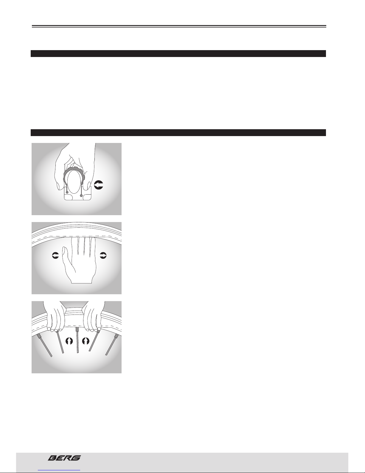
40
// USER’S MANUAL
ENGLISH
RECOMMENDED PRESSURES FOR TIRES
e recommended pressure is present at the side of the tire must match the table.
Use it as a general guide.
BMX - 35-50 psi / 2-3.45 Bar
MOUNTAIN BIKE - 40-65 psi / 2.6-4.5 Bar
COMFORT BIKE - 70-90 psi / 4.8-6.2 Bar
ROAD BIKE - 110-125 psi / 7.6-8.5 Bar
HYBRID / CROSS BIKE - 60-100 psi / 4.1-6.9 Bar
HOW TO FIX A FLAT TIRE
If you need to repair a tire, follow these steps:
1. Remove the wheel from the bicycle.
2. Deflate the tire completely via the valve. Loosen the tire bead by
pushing it inward all the way around.
3. Press one side of the tire bead up over the edge of the rim.
Use tire levers, not a screwdriver, otherwise you may damage the rim.
4. Remove the tube, leaving one tire bead on the rim.
5. Locate the leaks and patch using a tube repair kit, carefully following
the repair kit instructions, or replace the tube.
Ensure that the replacement tube size matches the size stated on the
tire sidewall and that the valve is the correct type for your bicycle.
6. Match the position of the leak in the tube with the tire to locate the
possible cause and mark the location on the tire.
7. Remove the tire completely and inspect for a nail, glass, etc. and remove if located. Also inspect the inside of the rim to ensure there are no
protruding spokes, rust or other potential causes. Replace the rim tape
which covers the spoke ends, if damaged.
8. Remount one side of the tire onto the rim.
9. Using a hand pump, inflate the tube just enough to give it some shape.
10. Place the valve stem through the hole in the rim and work the tube
into the tire.
Note: Do not let it twist.
11. Using your hands only, remount the other side of the tire by pushing
the edge toward the center of the rim. Start on either side of the valve
and work around the rim.
12. Before the tire is completely mounted, push the valve up into the rim
to make sure the tire can sit squarely in position.
13. Fit the rest of the tire, rolling the last, most difficult part on using
your thumbs.
NOTE: Avoid using tire levers as these can easily puncture the tube or damage the tire.
14. Check that the tube is not caught between the rim and the tire bead at any point.
15. Using a hand pump, inflate the tube until the tire begins to take shape, and check that the tire bead
is evenly seated all the way around the rim. When properly seated, fully inflate the tire to the pressure
marked on the sidewall. Use a tire air pressure gauge to check.
16. Replace the wheel into the frame checking that all gears, brakes, axle nuts or quick release levers
are properly tightened.
MAINTENANCE
PUSH THE EDGE OF THE TIRE TOWARD
THE CENTRE OF THE RIM
REMOVE THE EDGE OF THE TIRE OF THE RIM
PUSH THE TIRE INTO THE RIM
Page 41
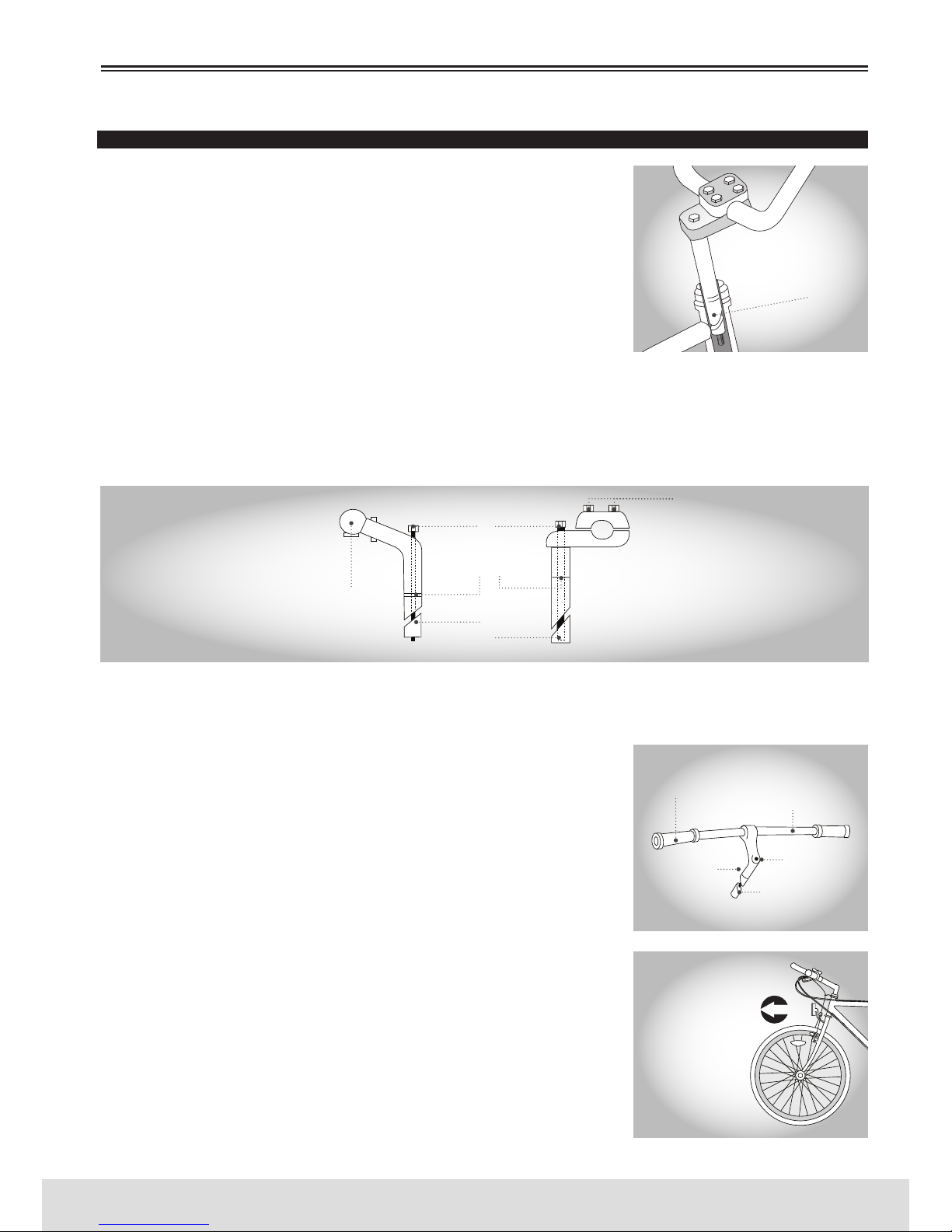
41
ENGLISH
www.bergcycles.com
HANDLEBAR AND STEM
STEM - e stem is placed on the steering column and is held tightly by
a screw and a expansive wedge, when pressed, unites with the inner
tube of the fork direction.
When you remove the stem, loosen the screw with the same two or
three turns and then give him an extra blow to loosen the wedge inside.
Before oiling, clean the grease and the dirt, and then apply a thin layer
of grease to the all part, including the wedge, which will be inserted
into the frame. e handlebar height can be adjusted to suit your preference and convenience. If you remove the stem of the steering column
you will see a mark about 65mm above the bottom with the words “maximum height “or “minimum
insertion”.
Never ride a bicycle if the stem is raised in way that you can see the line of maximum height / minimum
insertion. If you over tight the stem bolt or the assembly of the headset, this may result in damage to
the bicycle and / or injury to the cyclist.
When you re-adjust the stem, make sure that the handlebar is properly aligned and tightened, using the
appropriate hexagonal wrench or Allen wrench.
DO NOT OVER TIGHTEN
Check the handlebar safety in the stem and the stem in the fork tube,
place the front wheel between your knees and move the handlebar up
and down and from side to side. e handlebar should not move when
pressure is applied when turning.
HANDLEBAR
e exact position of the handlebar is a matter of personal comfort. For
mountain bikes (MTB), the bar should be in a approximately horizontal
position with the ends pointing backward and slightly upward. In BMX
bikes, the handlebar should remain in an approximately straight position, but you can move it slightly back or forward, for your convenience.
In MTB or road bikes, the handlebar is usually tight to the stem by an
Allen screw or a hexagonal screw. In BMX bikes, there may be four
tightening screws.
Keep in mind that if at some point you need to replace the fork of your
bike, you should consult a qualified bicycle technician.
MAINTENANCE
MAXIMUM HEIGHT
MINIMUM INSERTION
MARK
HANDLEBAR RETENTION
SCREW
MOUNTAIN BIKE (MTB)
HANDLEBAR ASSEMBLY
MAKE SURE THAT THE
HANDLEBAR AND FORK
ARE FACING FOWARD
PLEASE NOTE THAT
THE INCLINATION OF
THE FORK CURVE FACE
FOWARD
GRIP
HANDLEBAR
STEMBOLT
STEM
STEM BOLT WEDGE
HANDLEBAR CLAMP
BOLTS
STEM BOLT
MAXIMUM HEIGHT
MINIMUM INSERTION
MARK
STEM BOLT WEDGE
Page 42
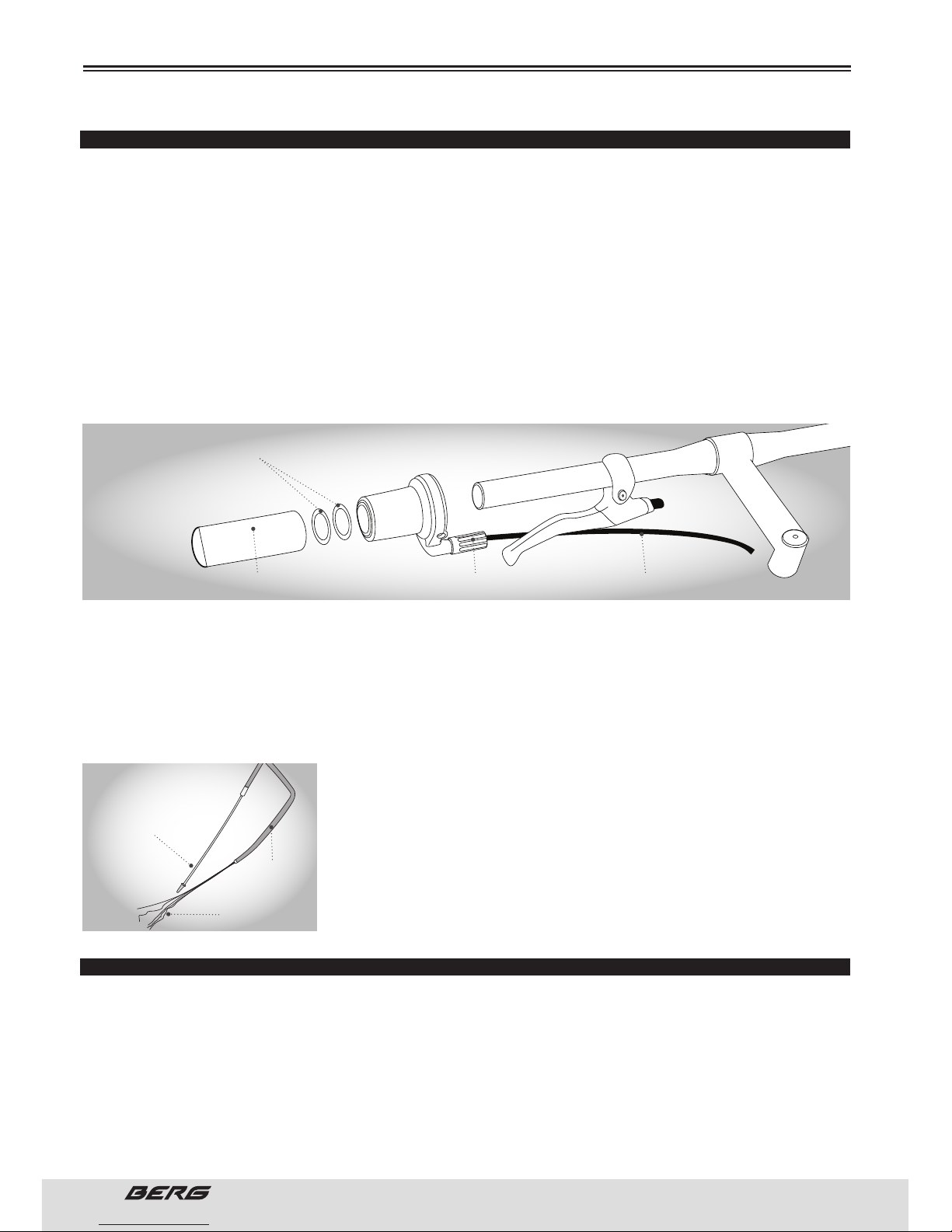
42
// USER’S MANUAL
ENGLISH
GRIP SHIFT
INSTALLING THE GRIP SHIFT ™
1. Slide the assembly of the Grip Shift™ over the left handlebar leaving the suitable space for the handle.
If necessary, move the brake lever to accommodate the Grip Shift™ and handlebars.
2. Rotate the assembling until the cable exits underneath the brake lever with the proper clearance to
move the brake lever.
3. Securely tighten the screw. e twisting torque of the system should be 20 inch-lbs / 2.25 N.m.
4. Slide the plastic washers on the handlebar. e washers prevent the handle to interfere with the rotation of the Grip Shift™.
5. Slide the grip on the handlebar. Pass the wire inside the cable through the cable spirals and the frame,
tighten to the derailleur.
Make sure the cable is in the V-groove in the derailleur tightening screw. If you need to cut the spiral
cable, make sure you put the terminal back the extremity of the spiral.
6. Adjust with the forefinger.
7. Slide the back Grip Shift over the right side of the handlebar and repeat steps 2-6.
8. Operate the front and rear brake levers to ensure that they work properly. If the Grip Shift™ interferes
with the movement of the brake lever, turn the brake lever or the Grip Shift™. Recheck if the brake lever
works properly.
CABLES AND CABLE HOUSING
Cables and housing are one of the most overlooked parts on the bicycle.
e first indication that your cables and housing need to be replaced
is an increased amount of pressure needed to operate the brakes or
shifters. Before every ride, check that there are no kinks or frays in the
cables and housing. Also check that the housing is seated properly into
each cable stop of the bicycle. It is recommended that the cables and
housing are replaced at least every riding season to prolong the life of
your bike.
HEADSET
INSPECTION
e headset bearing adjustment should be inspected every month. It is important because the headset is
what blocks the fork in the frame and, if released, can cause damage or an accident. While standing over
the frame top tube with both feet on the ground, press the front brake firmly and push the bike back and
forth, if you notice a certain lack of firmness in the headset, you should adjust it. Make sure the headset
is not too tight to the fork by slowly turning to the right and left. If the fork tends to stop or stall at some
point, the bearings are too tight.
MAINTENANCE
PLASTIC WASHER
GRIP TENSOR CABLE
GOOD CABLE
FOLD
WEAR
Page 43
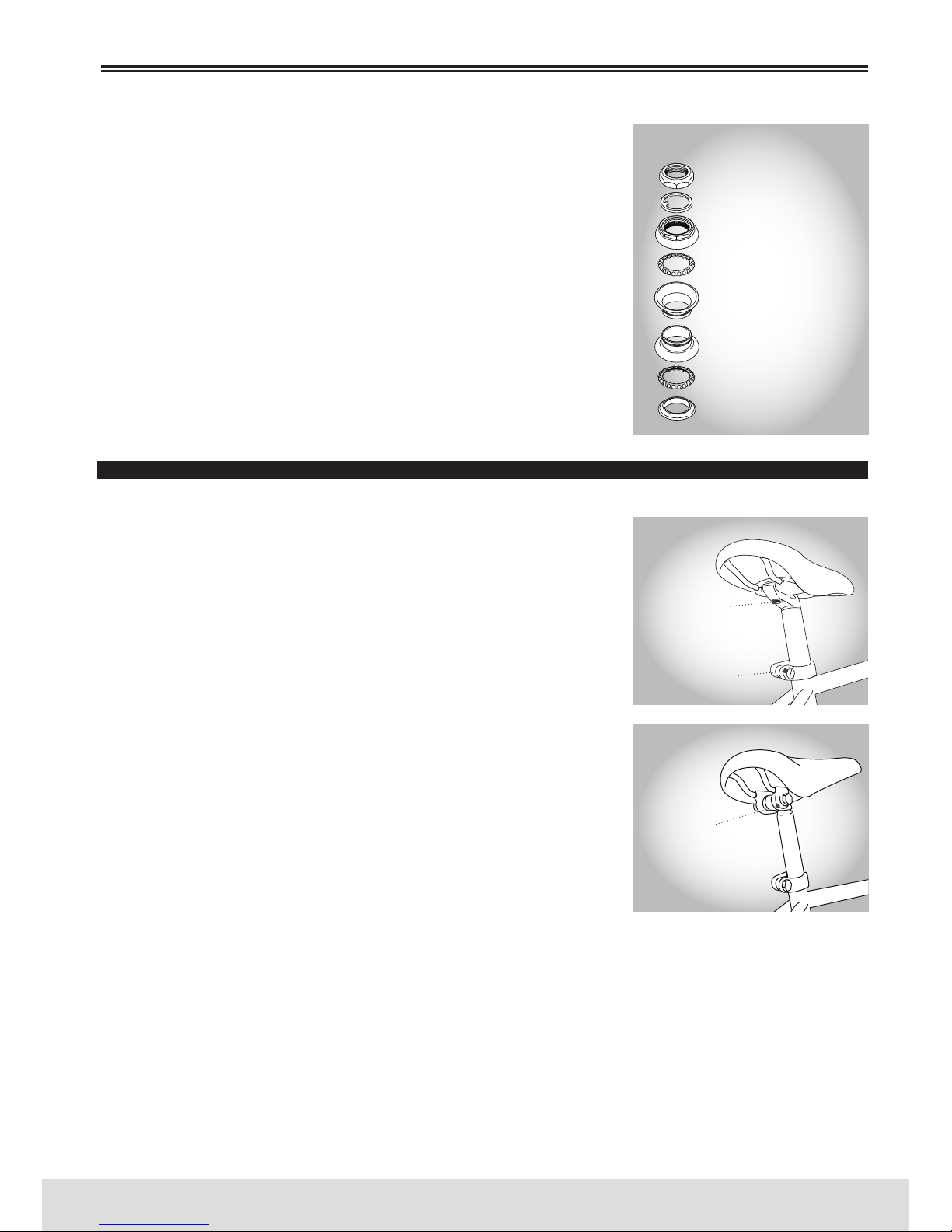
43
ENGLISH
www.bergcycles.com
If your bike is equipped with a threadless headset, see a qualified specialist in repairs and adjustments.
ADJUSTMENT
Loosen the upper lock nut of the headset or remove it completely along
with the support of the reflector if placed. Turn the body in a clockwise
direction until it is adjusted.
Replace the Lock washer or the mounting of the reflector and retighten
the upper lock nut with proper wrench.
Do not over tighten, might damage the bearing.
Always make sure that the headset is properly adjusted and that the
headset locknut is fully tightened before riding the bicycle.
If you tighten the stem bolt or assemble the headset in excess, you
may damage the bike and / or injury the rider.
SADDLE E SEATPOST
INSPECTION
e fixation screw on the saddle and the fixation screw on the saddle seatpost should be monthly reviewed to ensure that they are well
placed and tightened. If you take the saddle seatpost from the frame
you will see a mark about 65mm above the bottom with the words
“maximum height “or “minimum insertion”.
To prevent damage to the saddle seatpost, or potentially to the cyclist,
the minimum insertion mark must be inside the frame.
LUBRICATION
Remove the seatpost saddle from the frame and clean any greasy
stains, rust or dirt.
en apply small amount of fat on the new part that fits into the frame.
Insert, press to adjust the saddle seatpost on the frame.
ADJUSTMENT
As previously mentioned, the saddle height, angle and distance from
the handlebar can be adjusted to suit the preferences of each rider.
e angle of the saddle is a matter of personal preference, but is usually
in a more comfortable position when the top of the saddle is almost
parallel to the floor or slightly raised in front.
e saddle can also be adjusted by sliding forward or backward on the mounting rails to reach the handlebar with greater convenience.
When you place the saddle seatpost, place it beneath loosely. Set it in the desired angle and position,
and tighten the clamp mechanism.
ere are two types of frequent use saddle clamps. e most common employs a steel clamp with hexagonal nuts on each side to tighten. e other type, known as micro-adjustable clamp, uses an single
Allen screw head vertically mounted to tighten. After putting the saddle on the seatpost in the desired
position, adjust the height to the required level and tighten the screw.
Keep in mind that the fixation screw can be a hexagonal screw, an Allen head screw or a quick-release
mechanism. e saddle seatpost quick release mechanism is the same for the hubs with quick release
MAINTENANCE
SAFETY NUT
SAFETY WASHER
ADJUSTMENT CUP/CONE
SPHERES RETAINER
UPPER STEERING CUP
BOTTOM STEERING CUP
SPHERES RETAINER
CROWN RING
STANDARD HEADSET
SADDLE RETENTION
SCREW
SADDLE LOCKOUT
MICRO ADJUSTABLE SADDLE SEATPOST
STANDARD SADDLE SEATPOST
SADDLE SEATPOST
RETENTION SCREW
Page 44
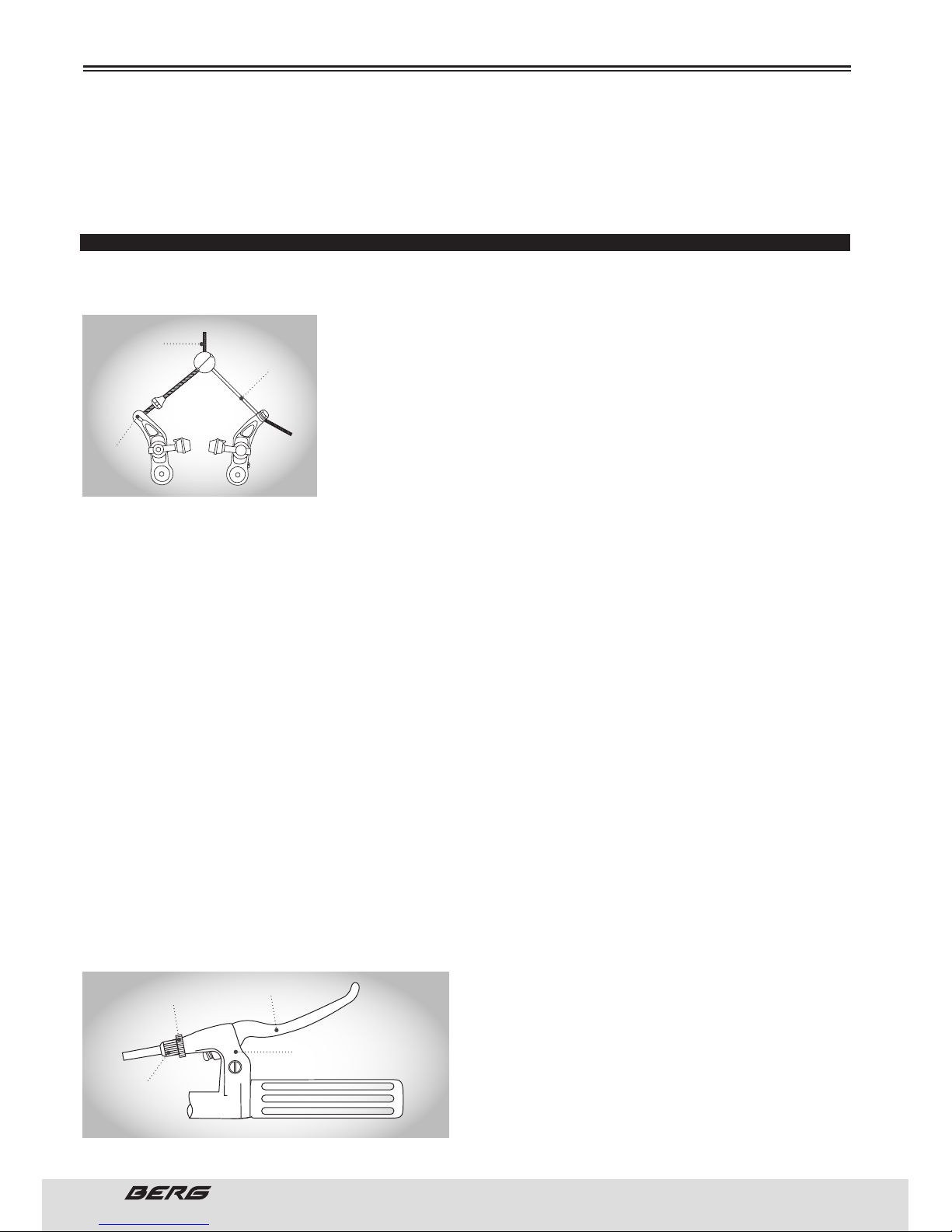
44
// USER’S MANUAL
ENGLISH
MAINTENANCE
system. (See pages 49 to 51.)
Check the security by grabbing the saddle and trying to rotate it to the sides. If it moves, you should
tighten the screw.
Remember that the minimum insertion mark must remain within the frame.
BRAKES
e correct adjustment and operation of your bicycle’s brakes is extremely important for safe operation.
Brakes should be checked for effective operation before every ride. Frequent checking of adjustment
is necessary as the control cables will stretch and the brake pads will
become worn with use.
Never ride a bicycle whose brakes do not work properly.
ere are two types of bicycle hand brakes, with lateral traction calibrators and cantilever calibrators. Both use handlebar-mounted lever that
controls a charge cable to activate the brake. e lateral traction brakes
are mounted on the side of the frame or fork over a single pivot point.
e cantilever brakes use the pivot arms, each one mounted on separate pivots on each side of the frame/fork.
INSPECTION
Brake levers should be checked for tightness at least every three months. ey should be set in a comfortable position within easy reach of the rider’s hands, and must not be able to move on the handlebar.
Some brake levers make use of a reach adjustment screw, which can alter the distance between the
handlebar grip and the lever, as required. e brake pads should be checked for correct positioning and
tightness before every ride, and the various bolts and nuts at least every three months. Squeeze each
brake lever to make sure they operate freely and that the brake pads press hard enough on the rims
to stop the bike. ere should be about 1mm - 2mm clearance between each pad and the rim when the
brakes are not applied. e brake pads must be properly centred for maximum contact with the rim. Replace the brake pads if they are over worn so that the grooves or pattern cannot be seen. e brake cable
wires should be checked for kinks, rust, broken strands or frayed ends. e outer casing should also be
checked for kinks, stretched coils and other damage. If the cables are damaged, they should be replaced.
Some brakes have a quick-release mechanism to allow the wheel to be removed more easily. Each time
you adjust the brakes, make sure that the quick-release mechanism is in closed position.
Never use bicycle unless the quick release lever is securely locked in the closed position.
LUBRICATION
e brake lever and brake calliper pivot points should be oiled with 2-3 drops of light oil at least every
tree months to ensure smooth operation and to reduce wear.
Cables should be greased along their entire length, after removing them from their casings, at least
every six months.
ADJUSTMENT
Minor brake adjustment can be made via the cable
regulator, usually located at the brake lever. To adjust,
squeeze the brake pads against the rim, loosen the
lock nut and turn the adjuster Brake pad clearance
should be a maximum 2mm from the rim. (1/2mm for
disc brakes) When correct, re-tighten the lock nut.
If the pads cannot be set close enough to the rim in
BIFURCATED
BRAKE CABLE
BRAKE
ARM
BRAKE
CABLE
CANTILEVER BRAKES
LOCKNUT
BRAKE LEVER
CABLE REGULATOR
BRAKE LEVER
COVER
Page 45
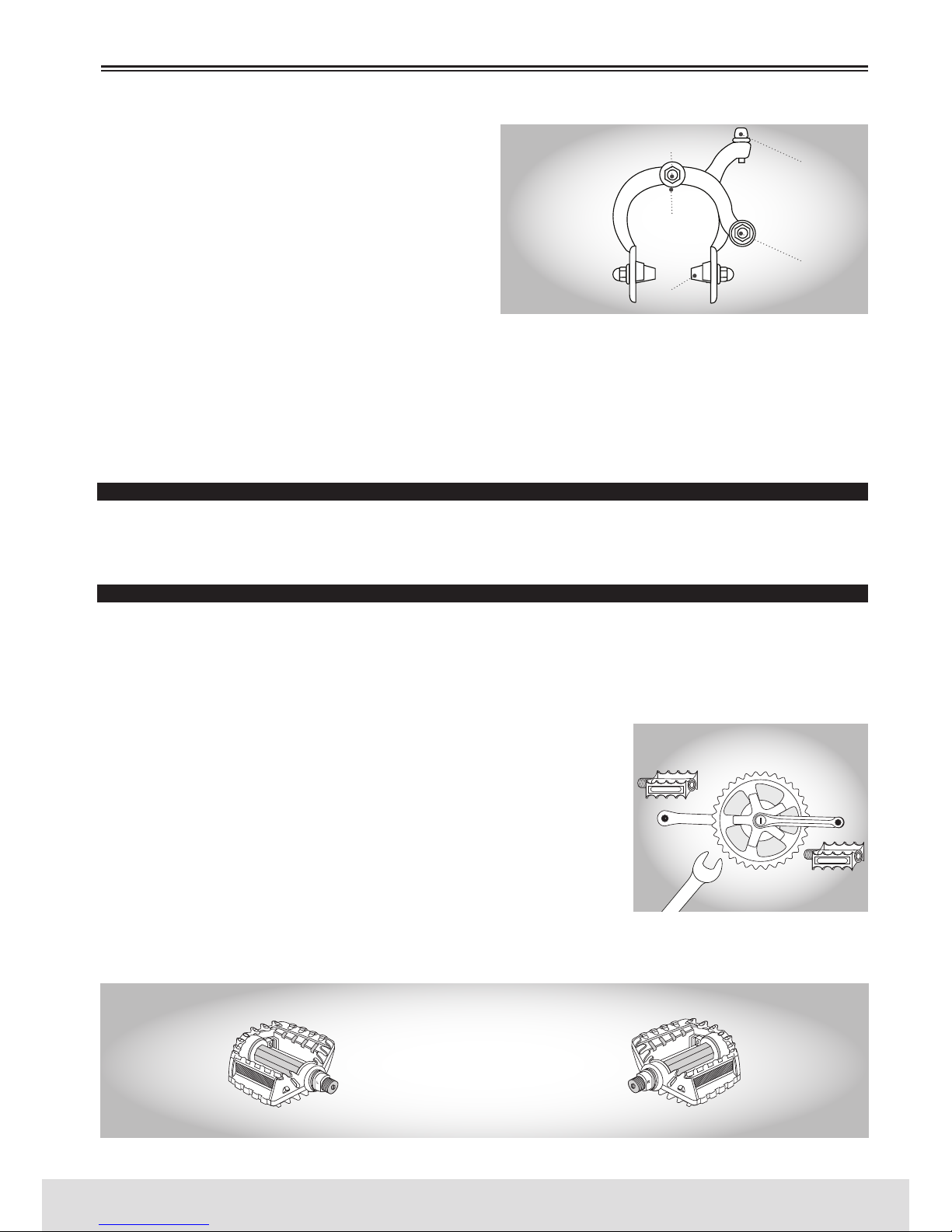
45
ENGLISH
www.bergcycles.com
MAINTENANCE
this manner, you may have to adjust the cable length.
Screw the barrel adjuster 3/4 of the way in, squeeze
the pads against the rim, undo the cable anchor bolt
and pull the cable through with pliers. Re-tighten the
cable anchor bolt and apply full force to the brake lever to test, then fine tune using the barrel adjuster. If
one pad is closer to the rim than the other, loosen the
fixing nut at the back of the brake, apply the brake to
hold it centred, and re-tighten the fixing nut.
Ensure the Brake fixation nut is secured tightly. Failure to do this may cause the brake assembly to
dislodge from the frame or fork.
Some brakes have a special mechanism which enables you to set the clearance on either side of the rim
using a screwdriver. Brake pads should finally be adjusted so that the leading edge of the pad makes
first contact with the rim. Some brakes have special curved washers to allow this, but on less complex
models it will be necessary to apply a little force to the pad and its mounting.
For more information refer to pages 25 to 28.
DRIVETRAIN
e drivetrain of a bicycle refers to all parts that transmit power to the rear Wheel including the pedals,
chain, chainwheel, crank set, and freewheel.
PEDALS
e pedals can be found in many shapes, sizes and materials, each one designed taking into account a
particular purpose. Some pedals can be fitted with fasteners and belting. ese help to keep feet correctly positioned and allow riders to use force and downward pressure on the pedals. e use of fasteners
and straps require some practice to acquire the necessary skills to use them safely.
INSPECTION
Pedals should be inspected every month, taking note of the following
areas:
Check correct tightness into the crank arms. If pedals are allowed to
become loose, they will not only be dangerous but will also cause irreparable damage to the cranks.
Check that pedal bearings are properly adjusted. Move the pedals up
and down, and right to left, and also rotate them by hand. If you detect
any looseness or roughness in the pedal bearings then adjustment, lubrication or replacement is required.
Ensure that the front and rear pedal reflectors are clean and securely fitted.
Never ride a bicycle if the pedals are not properly secured.
CENTRAL BOLT
LATERAL TRACTION
BRAKES
FIXATION NUT
REAR
CABLE RETENTION
SCREW
L = LEFT
R = RIGHT
ROTATE ANTICLOCKWISE
TO TIGHTEN
ROTATE CLOCKWISE TO
TIGHTEN
CABLE REGULATOR
BREAK PAD
Page 46
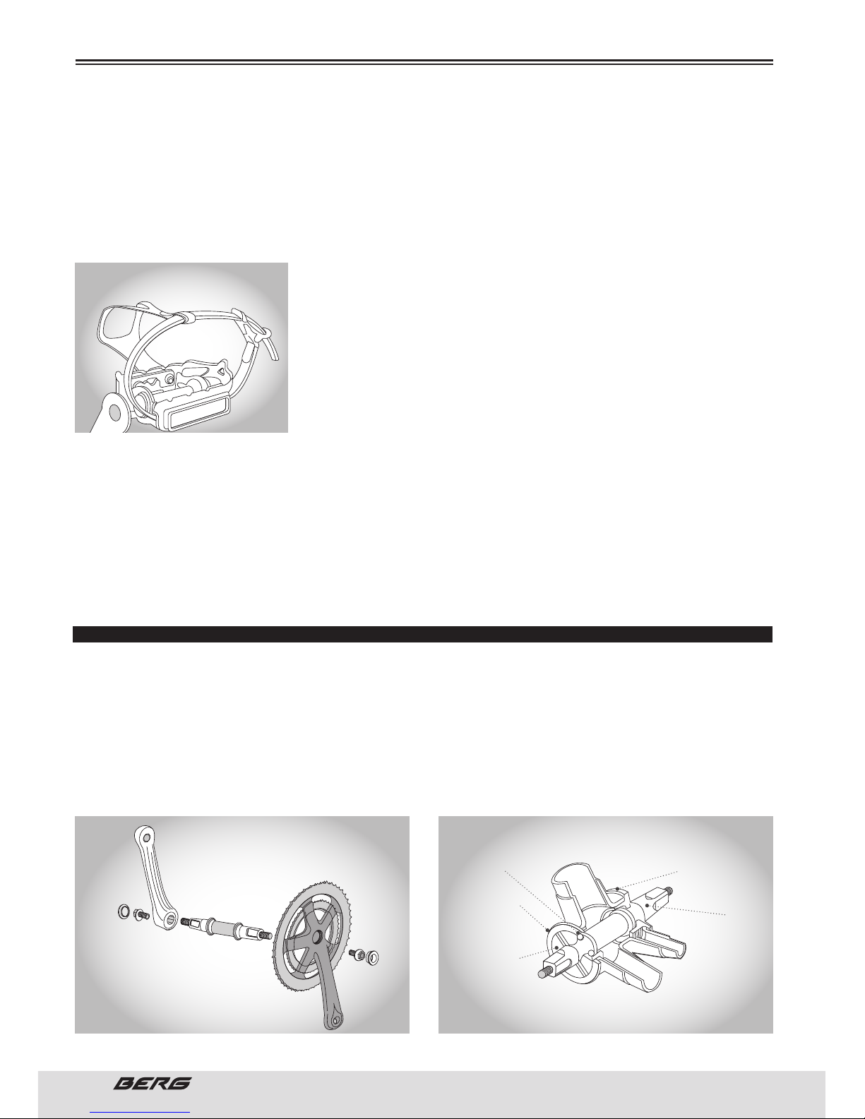
46
// USER’S MANUAL
ENGLISH
MAINTENANCE
LUBRICATION AND ADJUSTMENT
Many pedals cannot be disassembled to allow access to the internal bearings and axle. However, it is
usually possible to inject a little oil onto the inside bearings, and this should be done every six months. If
the pedal is the type that can be fully disassembled, then the bearings should be removed, cleaned and
greased every six to twelve months. Because of the wide variety of pedal types and their internal complexity, disassembly procedures are beyond the scope of this manual and further assistance should be
sought from a specialist.
Never ride a bike in traffic locations, with fully tightened fasteners.
e right and left pedals of the bicycle have different threads and can
not be changed. Never force a pedal into the crank.
e right pedal, which stands on the side of the sprocket, is marked
with a “R” on the shaft end, and twists itself in a clockwise direction.
e left pedal, which stands on the other hand, is marked with a “L” on
the shaft, and twists itself in the opposite direction.
Enter the correct pedal crank and start in the screwing it by hand. When
the shaft is completely screwed, tighten with 15mm Allen wrench.
If you want to remove a pedal, remember that the right pedal shaft must be rotated counter clockwise,
i.e. in the opposite direction of its placement. If you want to replace the original pedals for a new game,
make sure that the size and shaft threads are compatible with your bicycle crank. Bikes use one of two
types of crank shafts and they have different threads. It is possible that your bicycle is equipped with
a one piece crank, with no separated shaft. ese work with pedals that have ½” (12.7mm) threads.
Bicycles equipped with three parts brackets with a separate shaft, left and right crank, use a slightly
larger thread with ⁹/
₁₆”
(14mm).
Never force a pedal with a wrong size screw into the crank.
CRANKSET
e crankset set must be inspected before each use.
Check if it is properly adjusted and tight.
Check if the nuts / bolts that tighten the crank to the axle bracket are properly tightened.
Check the pedals tightness (crankset). e right pedal can be tightened with a 15mm screwdriver or in
some cases with 6mm Allen wrench. is tightening is done in a clockwise direction. For the left pedal,
the tightening is done in reverse.
Never ride a bicycle if the wrenchless cranksets are badly tightened. is can be dangerous and damage
the crank with no possibility of repair.
PEDAL WITH TIGHTENED FASTENERS
CRANKSET
SPHERES BEARING
SAFETY RING
ADJUSTEMENT
LATHE
FIXED LATHE
AXLE
STANDARD CRANKSET ASSEMBLY
Page 47
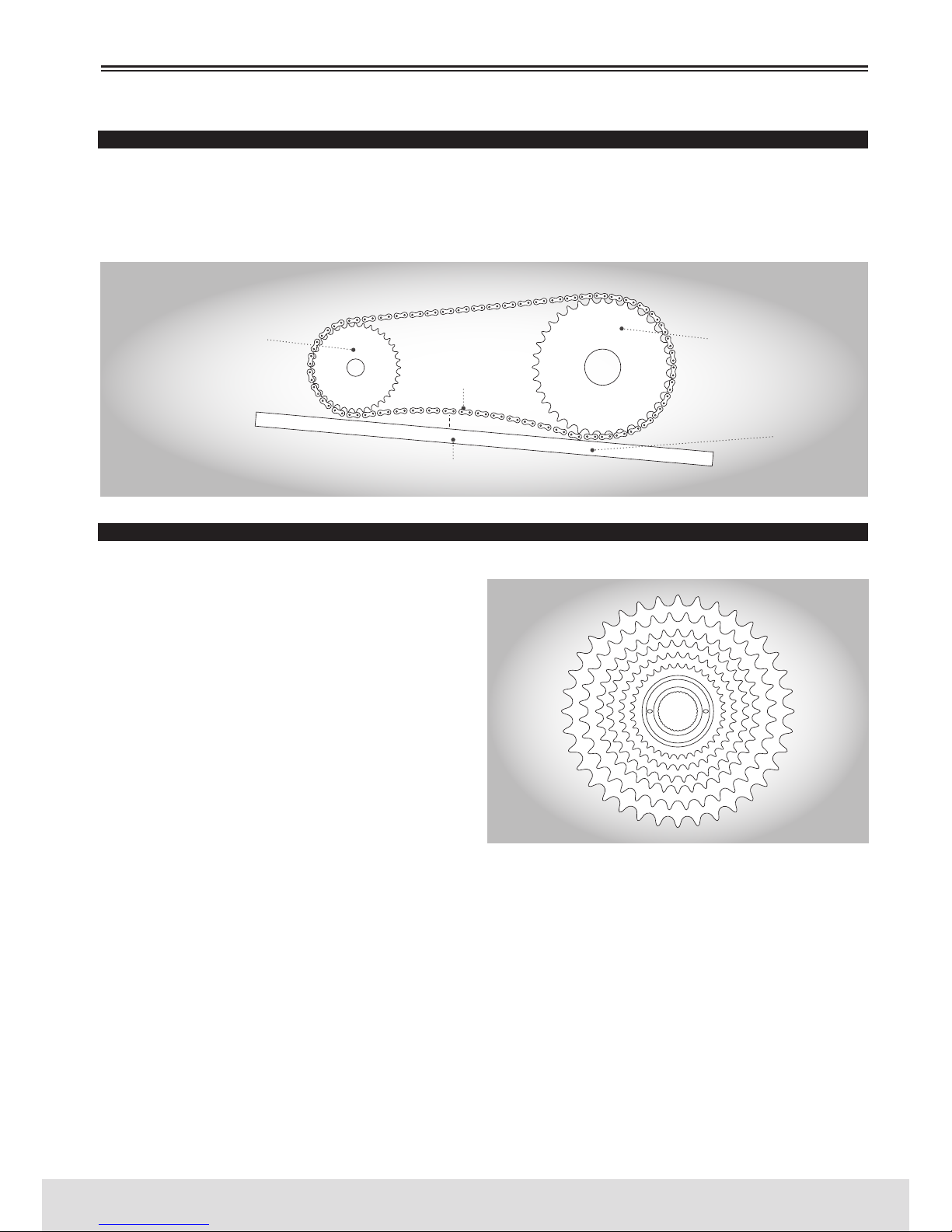
47
ENGLISH
www.bergcycles.com
MAINTENANCE
CHAIN
INSPECTION
e chain must be kept clean, rust free and frequently lubricated in order to extend its life as long as
possible. It will require replacement if it stretches, breaks, or causes inefficient gear shifting. Make sure
that there are no stiff links, they must all move freely.
FREEWHEEL
INSPECTION
Like the chain, the freewheel must be kept clean
and well lubricated. If the chain has become worn
and needs replacing, then it is likely that the freewheel will also have become worn and should also
be replaced. Take the chain off the freewheel and
rotate it with your hand. If you hear a grinding
noise or the freewheel stops suddenly after spinning it, it may need adjustment or replacement.
REAR SPROCKET
RAISE
10mm
FRONT CHAINRING
LEVELING RULER
Page 48
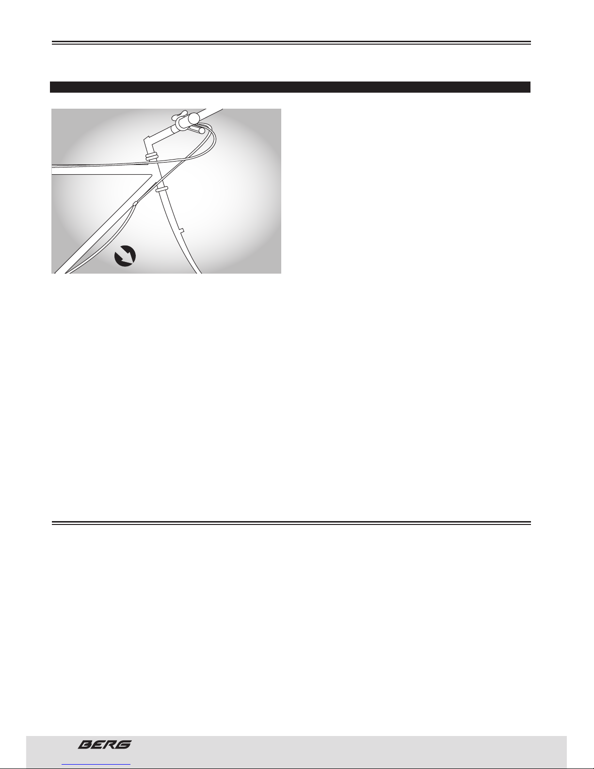
48
// USER’S MANUAL
ENGLISH
DERAILLEUR SYSTEM
e derailleur system includes the front and rear
derailleurs, the shift levers, and the derailleur control cables, all of which must function correctly for
smooth gear shifting to occur. ere are several different types of derailleur systems but all operate using similar principles. For the rear shifter, there will
be a positive “click” for each gear.
When properly adjusted, one click should change
one gear at a time. For the front shifter (if equipped)
some shifters are a “friction” system, where you
move the shifter until the desired shift occurs. Others have the same audible “click” to indicate that one
gear has been changed. e adjustments are similar.
INSPECTION
e operation of the derailleur system should be checked at least every month. Check the operation of
the rear derailleur first, then the front. e rear derailleur should shift the chain cleanly from one cog
to the next without hesitation. Each notched position in the shifter must equate to a new gear position.
After shifting, the rear derailleur should not rub on the chain. e derailleur should never cause the chain
to fall off the inner or outer freewheel cogs.
e front derailleur should also shift the chain cleanly and without hesitation between each chainring. If
your bicycle is equipped with front indexing (a click between gears), then each click or stop in the shifter
should equate exactly to a new gear position. When the chain has been positioned onto a new chainring,
it should not rub on the front derailleur. e chain should not fall off a chainring at any time. Derailleur
control cables are a critical component that must be well maintained for accurate shifting performance.
Check them for any sign of rust, fraying, kinks, broken strands and any damage to the cable housing. If
you find any problems, the cables may need replacing before you ride.
Consult page 42.
It is very important to understand how the different components of your bike work, to use them effectively, pleasantly and safely. Even if you are an experienced cyclist, do not assume that the operation
of your new bike is the same as other bikes from previous models. Be sure to read and understand this
section of the Handbook. Given the slightest doubt, consult a qualified technician.
When riding a bike with a quick release mechanism set incorrectly, it is possible for the wheel to wobble
or come off the bike and cause damage on the bike and serious injuries to the cyclist, including death.
It is therefore essential that:
1. Be sure to learn how to securely install and remove the wheels.
2. Understand and apply the correct technique for holding the wheel in place with a quick opening system.
3. Each time you ride the bike check if the wheel is securely fastened.
MAINTENANCE
HOW THE COMPONENTS WORK
STRETCH PREVIOUSLY THE
DERAILLEUR CABLES TO PREVENT
THEM FROM BECOMING WEARY
STRETCH
Page 49
49
ENGLISH
www.bergcycles.com
e quick release wheel system, was invented in the 1930s to allow quick and easy removal of the wheel
without the need for tools, this has become standard equipment on most bikes for recreation, sports
and competition. Although it seems only a wide screw with a lever at one end and a nut at the other,
the system uses quick release cam action to hold the bicycle wheel in place. Because of its adjustable
nature, it is essential to understand how it works and how to use it appropriately.
e full force of the cam action is necessary to hold the wheel safely.
Hold the nut with one hand and rotate the lever as a wing nut with another until is as tight as possible,
this will not tighten the wheel securely into the slots.
1. ADJUSTING THE QUICK RELEASE MECHANISM
e hub of the wheel is attached in place by force of the cam quick-release mechanism that pushes it
against a slot and pulls the tension adjusting nut through the bolt, against the other slot. e level of
strength is controlled by the fixing nut tension adjustment. By turning the tension adjustment nut in
the a clockwise direction, while keeping the cam lever to turn, increases the clamping force; rotate anticlockwise while keeping the cam lever to turn, the strength of fixation decreases. Less than half turn
of the back tension adjustment nut can make the difference between the strength for an insecure and
secure attachment.
Being the manufacturer or distributor to install the quick release system on the axis of the hub, you
should never remove it unless the hub needs to be arranged. If the hub requires assistance, consult a
specialist.
2. FRONT WHEEL SECONDARY RESTRAINING DEVICES
Many bicycles have front forks which use a secondary retention device of the wheel, so that the wheel
does not leave the quick release mechanism if not properly tightened. Secondary restraints do not replace proper adjustment of the quick release lever.
ese devices are divided into two basic categories:
a) e type of dock that is an accessory the manufacturer incorporates in the hub of the front wheel or
fork.
b) e integral type that is moulded cast or machined on the external sides of the fork tips. Ask your
dealer who will explain what specific type of secondary retention your bike has.
Remove or disable the secondary retention device is extremely dangerous and can cause serious injury
or death. It may also invalidate the warranty.
3. REMOVE OR INSTALL WHEELS WITH QUICK-RELEASE MECHANISM
a) Remove the front wheel with quick-release mechanism
(1) Open the brake shoes.
(2) Turn the quick release wheel lever from a locked or CLOSED position to the OPEN position.
(3) If the fork has a secondary retention device, skip to Step 5.
(4) If the fork has a secondary retention device of the plug type, unplug it and go to step 5. If the fork
has an integral secondary retention device, loosen the tension enough to remove the wheel, and then
go to step 5.
(5) Lift the front wheel a few inches of the soil, and take a small hit at the top of the wheel with the palm,
to release the wheel from the fork.
b) How to install a front wheel with quick-release mechanism
(1) Rotate the quick release lever so that it distances from the wheel, forming a curve. is position is
OPEN.
(2) With the steering fork facing forward, insert the wheel between the legs of the fork, so that the axle
seats firmly at the top of the slots that are at the ends of the legs - the tips of the fork. e quick release
lever should be on the left side of the bike. If your bike has a secondary restraint system, activate it.
(3) Holding the quick opening lever in the OPEN position with your right hand, adjust the tension with the
HOW THE COMPONENTS WORK
Page 50
50
// USER’S MANUAL
ENGLISH
HOW THE COMPONENTS WORK
left hand until its tighten against the tip of the fork.
(4) While pushing the wheel firmly to the upper slots of the fork tips, centre the wheel rim with the fork,
turn the quick release lever up and push it to the CLOSED position (see pages 24 to 25). e quick-release lever should be in a position parallel to the fork leg and curved toward the wheel.
If you can fully close the quick release lever without engaging your fingers in the fork of the paddle to
push, and the lever does not leave a clear imprint in the palm of your hand, tension is insufficient. Open
the lever, give it a quarter turn in a clockwise direction to the tension adjustment nut, then try again to
close the lever.
(5) If you can not push the lever to a parallel position to the fork blade, place it in the OPEN position. en
take a quarter turn counter clockwise on the tension adjusting nut and try tightening the lever again.
Secondary restraints devices do not replace the proper adjustment of the quick release lever. If the
quick-release mechanism is not properly adjusted, the wheel may wobble or become loose, which could
cause you to lose control and fall, causing serious injury, including death.
c) How to remove a rear wheel with quick-release mechanism
(1) Move the rear derailleur to higher gear (the outer rear wheel, smaller).
(2) Open the brake pads.
(3) Pull the derailleur back with your right hand.
(4) Rotate the quick release lever to the OPEN position.
(5) Lift the rear wheel off the ground a few inches and, with the derailleur still pulled back, push the
wheel forward and down until it comes out of the rear dropouts.
d) How to install a rear wheel with quick-release mechanism
(1) Move the rear derailleur to its outside position.
(2) Pull the derailleur back with your right hand.
(3) Turn the quick release lever to the OPEN position. e lever should be on the side of the opposite
wheel to the derailleur and cassete.
(4) Place the chain on the smallest sprocket of cassete. en, insert the wheel into the frame dropouts
and pull it up.
(5) Tight the adjusting nut until its tighten against the frame, then turn the lever to the front of the bike
to be in a position parallel to the chain base frame or to the riser and stay bended towards the wheel.
If you can fully close the quick release lever without engaging your fingers in the fork of the paddle to
push, and the lever does not leave a clear imprint in the palm of your hand, tension is insufficient. Open
the lever, give the adjustment nut a quarter turn in a clockwise direction to adjust the tension, then try
again to close the lever.
(6) If you can not push lever to a position parallel to the base of the chain or saddle tube, reinsert it
into the OPEN position. en adjust the nut in a quarter turn counter clockwise and try tightening again.
(7) Push the rear derailleur back until it seats on its position.
(8) Close the brake pads, and then turn the wheel to make sure it is centred in the frame and that does
not obstruct the brake pads.
4. HOW TO REMOVE AND INSTALL WHEELS SECURED WITH SCREWS
a) Remove the front wheel secured with screws
(1) Open the brake pads.
(2) With a 15mm wrench or an adjustable six-inch wrench, loosen the two axle nuts.
(3) If the fork has a secondary retention device plug, unplug it and go to step 4. If the fork has an integral
secondary retention device, loosen the axle nuts with approximately six full turns, then go to step 4.
(4) Raise the front wheel a few inches above the ground, and give a small stroke at the top of the wheel
with the palm of your hand to take the wheel of the fork.
b) How to install a front wheel secured with screws
(1) With the steering fork facing forward, insert the wheel between the fork blades so that the axle seats
firmly at the top of the slots that are on the tips of the fork blades. e spindle nut washers must be on
Page 51
51
ENGLISH
www.bergcycles.com
HOW THE COMPONENTS WORK
the outside, between the shovel and fork axle nut. If your bike has a secondary retention device, connect it.
(2) While pushing the wheel firmly to the top of the slots in the fork dropouts, centre the wheel rim in the
fork, use a 15 mm wrench or an adjustable six-inch wrench to tighten the axle nuts as much as possible.
(3) Close the brake pads, and then turn the wheel to make sure it is centred in the frame and does not
obstruct the brake pads.
c) How to remove a rear wheel secured with screws
(1) Open the brake pads.
(2) Move the rear derailleur to the highest gear (the smallest rear sprocket) and pull the derailleur back
with your right hand.
(3)Loosen the axle nuts with a 15 mm wrench or an adjustable six-inch wrench.
(4) Lift the rear wheel a few inches of soil and, with the derailleur still pulled back, push the wheel forward and down until it exit the rear dropouts.
d) How to install a rear wheel secured with screws
(1) Move the rear derailleur into its outside and pull the derailleur back with your right hand.
(2) Place the chain on the smallest sprocket. en, insert the wheel between the tips of the frame and
pull it up to the tips. e washers of the axle nuts must be on the outside, between the frame and axle
nut.
(3) Tighten the axle nuts as much as possible, using an adjustable wrench or a 15 mm six-inch wrench.
(4) Push the rear derailleur back until it gets into position.
(5) Close the brake, spin the wheel to make sure it is centred in the frame and does not obstruct the
brake pads.
B. SEAT POST CAM ACTION CLAMP
Some bikes are equipped with a cam action seat post binder. e seat post cam action binder works
exactly like the traditional wheel cam action fastener. While a cam action binder looks like a long bolt
with a lever on one end and a nut on the other, the binder uses an over-centre cam action to firmly
clamp the seat post.
Riding with an improperly tightened seat post can allow the saddle to turn or move and cause you to
lose control and fall.
erefore:
1. Ask your dealer to help you make sure you know how to correctly clamp your seat post.
2. Understand and apply the correct technique for clamping your seat post.
3. Before you ride the bike, first check that the seat post is securely clamped.
Adjusting the seat post cam action mechanism
e action of the cam squeezes the seat collar around the seat post to hold the seat post securely
in place. e amount of clamping force is controlled by the tension adjusting nut. Turning the tension
adjusting nut clockwise while keeping the cam lever from rotating increases clamping force; turning it
counter clockwise while keeping the cam lever from rotating reduces clamping force. Less than half a
turn of the tension adjusting nut can make the difference between safe and unsafe clamping force.
e full force of the cam action is needed to clamp the seat post securely. Holding the nut with one hand
and turning the lever like a wing nut with the other hand until everything is as tight as you can will not
clamp the seat post safely.
If you can fully close the cam lever without wrapping your fingers around the seat post or a frame tube
for leverage, and the lever does not leave a clear imprint in the palm of your hand, the tension is insufficient. Open the lever; turn the tension adjusting nut clockwise a quarter turn; then try again.
Page 52
52
// USER’S MANUAL
ENGLISH
HOW THE COMPONENTS WORK
C. BRAKES
For a more effective braking, use both brakes and apply them simultaneously.
e sudden or excessive use of the front brake can push the rider onto the handlebar and cause him
serious injury or death.
1. How brakes work
For your safety, it is important to know instinctively which brake lever controls which brake on your bike.
In the United States, bicycles must be mounted so that the right brake lever controls the rear brake, and
that the left brake lever controls the front brake.
e braking action of a bicycle is the result of the friction between the surfaces of the brakes, generally
brake shoes and the wheel rim. To make ensure maximum friction, keep your wheel rims and brake
shoes, clean and free of oils, waxes or polishes.
Make sure that your hands can reach and squeeze the brake levers comfortably. If your hands are too
small to operate the levers comfortably, consult your dealer before riding the bicycle. e range of the
lever may be adjustable, otherwise you will need a brake lever with a different design.
Most brakes have some kind of quick-release mechanism so that the brake shoes do not obstruct the
tire removal or reinstallation of a wheel. When the quick-release mechanism of the brake is in open position, the brakes do not work. Make sure you understand how the quick release mechanism of the brakes
works and inspect it to make sure both brakes work correctly every time you ride your bike.
e brakes are designed not only to stop the bike but also to control speed. e maximum braking force
for each wheel occurs at the exact point before the wheel “block” (stop running) and start sliding. When
the tire skids, you lose most of the braking force and complete control of direction. You must practice
slowing and stopping smoothly without locking a wheel. is technique is called progressive brake modulation. Instead of moving the brake lever to the position you think will generate the required braking
force, squeeze the lever while increasing in a progressive manner, the braking force. If you feel that the
wheel starts to lock, release some pressure, so that the wheel continues to walk without blocking. It is
important to develop a perception of the degree of pressure applied to the brake lever, which is required
for each wheel at different speeds and different surfaces. To understand this better, try to apply different
degrees of pressure on each brake lever, until the wheel lock.
Some bicycle brakes, such as linear pull brakes or disc brakes, are extremely powerful. Pay special
attention to get familiar with these types of brake and be extremely careful when using them. If these
brakes are suddenly applied or applied all at once, you can lock a wheel, which would lead you to lose
control and fall.
When you activate one or both brakes, the bike begins to slow, but its structure continues at the rate
it was. is causes a weight transfer to the front wheel (or, in a hard braking, around the front wheel
hub), which can cause your projection over the handlebar. A wheel with more weight on it will accept a
higher braking pressure before locking, a wheel with less weight will block with less braking pressure. So
when you apply the brakes and your weight shifts forward, you must move your body to the rear of the
bike, to transfer the weight to the rear wheel, and at the same time, reducing the rear braking force and
increasing the front braking force. is is even more important in abrupt descends, because the downhill
projects your weight forward. Tricks for speed control and effective safe braking consist on controlling
the wheels locking and the weight transfer. Practice the braking and weight transfer techniques in areas
without traffic or where there are no hazards or distractions.
Everything changes when you use the bike on uncompressed surfaces or wet weather conditions. e
tire grip is reduced, so that the wheels have less cornering grip and traction when braking, and can block
with less brake force. Moisture or dirt on the shoes brake reduces the grip. e way to maintain control
on wet or uncompressed surfaces is cycling at a lower speed.
Page 53
53
ENGLISH
www.bergcycles.com
HOW THE COMPONENTS WORK
2. Adjusting the brakes
If any of the brake levers from your bicycle presents a mechanical failure in the safety inspection, you
can restore the displacement of the brake lever by turning the brake cable tensioner counter clockwise,
then lock the adjustment turning the nut tensor lock in a clockwise direction. If the lever still do not pass
the mechanic safety inspection, or want to know if the brakes are working properly, ask your dealer to
inspect the brakes.
D. GEARS
Your multi-speed bicycle will have a derailleur drivetrain, an internal gear hub drivetrain or, in some case
a combination of the two.
1. Why all these gears?
You’ll get more benefit from physical fitness, you will produce a larger and continuous power and have
greater endurance to learn to spin the pedals at high rotations per minute (called cadence) against a
mild resistance. You will get less benefit from physical fitness and will have less ability to endurance if
pressing the pedals against a heavy resistance.
e purpose of multiple gears on a bike is to let you choose the gear that allows you to maintain an optimal cadence in various driving conditions. Depending on your level of fitness and experience (the higher
fitness, the higher the cadence), the optimal cadence is between 60 to 90 pedal rotations per minute.
2. How a derralleur drivetrain works
If your bicycle has a derailleur drivetrain, the gear-changing mechanism will have:
A rear cassette or freewheel sprocket cluster;
A rear derailleur;
Usually a front derailleur;
One or two shifters;
One, two or three front sprockets called chainrings;
A drive chain.
e number of possible gears combinations (“speeds”) is the result of multiplying the number of sprockets on the cassete by the number of chainrings in front (6x2 =12 / 6x3=18 / 7x3=21 and so on).
ere are many different types of gear mechanisms, each one designed for specific applications due to
its ergonomic features, efficiency and price.
Your bike designers have selected the design of the shifter that could present the best results on your
bike.
e vocabulary of shifting can be pretty confusing. A downshift is a shift to a “lower” or “slower” gear,
one which is easier to pedal. An upshift is a shift to a “higher” or “faster”, harder to pedal gear. What’s
confusing is that what’s happening at the front derailleur is the opposite of what’s happening at the
rear derailleur (for details, read the instructions on Shifting the Rear Derailleur and Shifting the Front
Derailleur below). For example, you can select a gear which will make pedalling easier on a hill (make a
downshift) in one of two ways: shift the chain down the gear “steps” to a smaller gear at the front, or
up the gear “steps” to a larger gear at the rear. So, at the rear gear cluster, what is called a downshift
looks like an upshift. e way to keep things straight is to remember that shifting the chain in towards
the centreline of the bike is for accelerating and climbing and is called a downshift. Moving the chain out
or away from the centreline of the bike is for speed and is called an upshift.
Whether upshifting or downshifting, the bicycle derailleur system design requires that the drive chain
be moving forward and be under at least some tension. A derailleur will shift only if you are pedalling
forward.
Page 54
54
// USER’S MANUAL
ENGLISH
HOW THE COMPONENTS WORK
1) SHIFTING THE REAR DERAILLEUR
e rear derailleur is controlled by the right shifter.
e function of the rear derailleur is to move the drive chain from one gear sprocket to another. e
smaller sprockets on the gear cluster produce higher gear ratios. Pedalling in the higher gears requires
greater pedalling effort, but takes you a greater distance with each revolution of the pedal cranks. e
larger sprockets produce lower gear ratios. Using them requires less pedalling effort, but takes you a
shorter distance with each pedal crank revolution. Moving the chain from a smaller sprocket of the gear
cluster to a larger sprocket results in a downshift. Moving the chain from a larger sprocket to a smaller
sprocket results in a upshift. In order for the derailleur to move the chain from one sprocket to another,
the rider must be pedalling forward.
2) SHIFTING THE FRONT DERAILLEUR
e front derailleur, which is controlled by the left shifter, shifts the chain between the larger and smaller
chainrings. Shifting the chain onto a smaller chainring makes pedalling easier (a downshift). Shifting to
a larger chainring makes pedalling harder (an upshift).
Which gear should I be in?
e combination of largest rear and smallest front gears is for the steepest hills. e smallest rear and
largest front combination is for the greatest speed. It is not necessary to shift gears in sequence.
Instead, find the “starting gear” which is right for your level of ability — a gear which is hard enough for
quick acceleration but easy enough to let you start from a stop without wobbling and experiment with
upshifting and downshifting to get a feel for the different gear combinations. At first, practice shifting
where there are no obstacles, hazards or other traffic, until you’ve built up your confidence. Learn to
anticipate the need to shift, and shift to a lower gear before the hill gets too steep.
It is recommended to avoid using gears combinations of extreme positions (scheme on page 21) for long
periods.
3. HOW AN INTERNAL GEAR HUB DRIVETRAIN WORKS
If your bicycle has an internal gear hub drivetrain, the gear changing mechanism will consist of:
A 3, 5, 7, 8, 12 speed or possibly an infinitely variable internal gear hub;
One, or sometimes two shifters;
One or two control cables;
One front sprocket called a chainring;
A drive chain.
a) Shifting internal gear hub gears
Shifting with an internal gear hub drivetrain is simply a matter of moving the shifter to the indicated
position for the desired gear ratio. After you have moved the shifter to the gear position of your choice,
ease the pressure on the pedals for an instant to allow the hub to complete the shift.
b) Which gear should I be in?
e numerically lowest gear (1) is for the steepest hills. e numerically largest gear is for the greatest
speed. Shifting from an easier, “slower” gear (like 1) to a harder, “faster” gear (like 2 or 3) is called an
upshift. Shifting from a harder, “faster” gear to an easier, “slower” gear is called a downshift. It is not
necessary to shift gears in sequence. Instead, find the “starting gear” for the conditions — a gear which
is hard enough for quick acceleration but easy enough to let you start from a stop without wobbling —
and experiment with upshifting and downshifting to get a feel for the different gears. At first, practice
shifting where there are no obstacles, hazards or other traffic, until you’ve built up your confidence.
Learn to anticipate the need to shift, and shift to a lower gear before the hill gets too steep.
E. TOE CLIPS AND STRAPS
Toe clips and straps are a means to keep feet correctly positioned and engaged with the pedals. e toe
clip positions the ball of the foot over the pedal spindle, which gives maximum pedalling power.
Page 55
55
ENGLISH
www.bergcycles.com
HOW THE COMPONENTS WORK
e toe strap, when tightened, keeps the foot engaged throughout the rotation cycle of the pedal. While
toe clips and straps give some benefit with any kind of shoe, they work most effectively with cycling
shoes designed for use with toe clips. Your dealer can explain how toe clips and straps work. Shoes with
deep treaded soles or welts which might make it more difficult for you to insert or remove your foot
should not be used with toe clips and straps. Getting into and out of pedals with toe clips and straps
requires skill which can only be acquired with practice.
Until it becomes a reflex action, the technique requires concentration which can distract your attention
and cause you to lose control and fall. Practice the use of toe clips and straps where there are no obstacles, hazards or traffic. Keep the straps loose, and don’t tighten them until your technique and confidence
in getting in and out of the pedals warrants it. Never ride in traffic with your toe straps tight.
F. CLIPLESS PEDALS
Clipless pedals (sometimes called “step-in pedals”) are another means to keep feet securely in the
correct position for maximum pedalling efficiency. ey have a plate, called a “cleat,” on the sole of the
shoe, which clicks into a mating spring-loaded fixture on the pedal. ey only engage or disengage with
a very specific motion which must be practiced until it becomes instinctive. Clipless pedals require shoes
and cleats which are compatible with the make and model pedal being used. Many clipless pedals are
designed to allow the rider to adjust the amount of force needed to engage or disengage the foot.
Clipless pedals are intended for use with shoes specifically made to fit them and are designed to firmly
keep the foot engaged with the pedal. Practice is required to learn to engage and disengage the foot
safely. Until engaging and disengaging the foot becomes a reflex action, the technique requires concentration which can distract your attention and cause you to lose control and fall. Practice engaging and
disengaging clipless pedals in a place where there are no obstacles, hazards or traffic; and be sure to
follow the pedal manufacturer’s setup and service instructions.
G. TIRES AND TUBES
1. TIRES
Bicycle tires are available in many designs and specifications, ranging from general-purpose designs
to tires designed to perform best under very specific weather or terrain conditions. Your bicycle was
equipped with tires that the manufacturer considered as the best balance between performance and value for the intended purpose. If, once you’ve gained experience with your new bike, you feel that a different tire might better suit your riding needs, your dealer can help you select the most appropriate design.
e size, pressure rating, and on some high-performance tires the specific recommended use, are
marked on the sidewall of the tire. e part of this information which is most important to you is Tire
Pressure.
Never inflate a tire beyond the maximum pressure marked on the tire’s sidewall. Exceeding the recommended maximum pressure may blow the tire off the rim, which could cause damage to the bike and
injury to the rider and bystanders.
e best and safest way to inflate a bicycle tire to the correct pressure is with a bicycle pump which has
a built-in pressure gauge.
ere is a safety risk in using gas station air hoses or other air compressors. ey are not made for
bicycle tires. ey move a large volume of air very rapidly, and will raise the pressure in your tire very
rapidly, which could cause the tube to explode.
Tire pressure is given either as maximum pressure or as a pressure range.
How a tire performs under different terrain or weather conditions depends largely on tire pressure. Inflating the tire to near its maximum recommended pressure gives the lowest rolling resistance; but also
produces the harshest ride. High pressures work best on smooth, dry pavement.
Page 56
56
// USER’S MANUAL
ENGLISH
HOW THE COMPONENTS WORK
Very low pressures, at the bottom of the recommended pressure range, give the best performance on
smooth, slick terrain such as hard-packed clay, and on deep, loose surfaces such as deep, dry sand.
Tire pressure that is too low for your weight and the riding conditions can cause a puncture of the tube
by allowing the tire to deform sufficiently to pinch the inner tube between the rim and the riding surface.
Pencil type automotive tire gauges can be inaccurate and should not be relied upon for consistent, accurate pressure readings. Instead, use a high quality dial gauge.
Check inflation as described so you’ll know how correctly inflated tires should look and feel when you
don’t have access to a gauge. Some tires may need to be brought up to pressure every week or two, so
it is important to check your tire pressures before every ride.
Some special high-performance tires have unidirectional treads: their tread pattern is designed to work
better in one direction than in the other. e sidewall marking of a unidirectional tire will have an arrow
showing the correct rotation direction. If your bike has unidirectional tires, be sure that they are mounted
to rotate in the correct direction.
2. TIRE VALVES
e tube valve allows the air to enter the inner chamber of the tire without pressure, but does not allow
it to escape, unless you want it. ere are primarily two kinds of bicycle tube valves (actually, there are
other types, but are not very common in Europe e Schraeder Valve and the Presta Valve. e bicycle
pump you use must have the fitting appropriate to the valve stems on your bicycle.
e Schraeder valve is like the valve on a car tire. To inflate a Schraeder valve tube, remove the valve cap
and clamp the pump fitting onto the end of the valve stem. To let air out of a Schraeder valve, depress
the pin in the end of the valve stem with the end of a wrench or other appropriate object.
e Presta valve has a narrower diameter and is only found on bicycle tires. To inflate a Presta valve tube
using a Presta headed bicycle pump, remove the valve cap; unscrew (counter clockwise) the valve stem
lock nut; and push down on the valve stem to free it up. en push the pump head on to the valve head,
and inflate. To inflate a Presta valve with a Schraeder pump fitting, you’ll need a Presta adapter (available
at your bike shop) which screws on to the valve stem once you’ve freed up the valve. e adapter fits
into the Schraeder pump fitting. Close the valve after inflation. To let air out of a Presta valve, open up
the valve stem lock nut and depress the valve stem.
e adapter fits on the end of air hose attachment. Close the valve after filling. To let air out of a Presta
valve, open the lock nut of the valve pin and press the pin.
H. BICYCLE SUSPENSION
e suspension must be in good condition to function properly.
e suspension must have a proper maintenance done by qualified personnel for this purpose, in order
to avoid errors that may cause a malfunction of the suspension.
Many bicycles are equipped with suspension systems. ere are many different types of suspension
systems too many to deal with individually in this Manual. If your bicycle has a suspension system of any
kind, be sure to read and follow the suspension manufacturer’s setup and service instructions. If you do
not have the manufacturer’s instructions, see your dealer or contact the manufacturer.
If the bike as been without use for along time, you should check the suspension.
Failure to maintain, check and properly adjust the suspension system may result in suspension malfunction, which may cause you to lose control and fall.
Changing suspension adjustment can change the handling and braking characteristics of your bicycle.
Never change suspension adjustment unless you are thoroughly familiar with the suspension system
manufacturer’s instructions and recommendations, and always check for changes in the handling and
braking characteristics of the bicycle after a suspension adjustment by taking a careful test ride in a
hazard-free area.
Page 57
57
ENGLISH
www.bergcycles.com
HOW THE COMPONENTS WORK
Not all bicycles can be safely retrofitted with some types of suspension systems.
If your bike has suspension, the increased speed you may develop also increases your risk of injury. For
example, when braking, the front of a suspended bike dips. You could lose control and fall if you do not
have experience with this system. Learn to handle your suspension system safely
Suspension can increase control and comfort by allowing the wheels to better follow the terrain. is
enhanced capability may allow you to ride faster; but you must not confuse the enhanced capabilities of
the bicycle with your own capabilities as a rider. Increasing your skill will take time and practice. Proceed
carefully until you have learned to handle the full capabilities of your bike.
Never ride at a speed or on a terrain that is not appropriate for your skills and driving experience. Always
proceed with caution in areas where you do not know the terrain. If you exceed your limitations, you may
suffer serious injury or even death.
Page 58

ADVERTÊNCIA/IMPORTANTE
Tenha em conta este símbolo em todo o manual e preste especial atenção às instruções marcadas e
precedidas pelo mesmo.
PORTUGUÊS
Page 59
59
PORTUGUÊS
www.bergcycles.com
ÍNDICE
1. SÉRIE DOS MODELOS E NORMAS
2. REGISTO DA GARANTIA
• GUIA DE TAMANHOS DE QUADRO
3. IDENTIFICAÇÃO DAS PARTES
• BICICLETAS DE MONTANHA
• BICICLETAS DE LAZER/TREKKING
• BICICLETAD DE ESTRADA
• BICICLETAS BMX/JUNIOR/CRIANÇA
• FERRAMENTAS NECESSÁRIAS
4. ANTES DE USAR A BICICLETA
• AJUSTES À BICICLETA
ALTURA DO SELIM
ALCANCE
ALTURA DO GUIADOR
• PLANO DE VERIFICAÇÃO DE SEGURANÇA E
MANUTENÇÃO
TRAVÕES
PNEUS/CAMARAS DE AR
RODAS
DIREÇÃO
SUPORTES/PEDAIS
MUDANÇAS
QUADRO/FORQUETA
CORRENTE/DESVIADOR/ALAVANCA DOS
TRAVÕES
ALAVANCA DAS VELOCIDADES
EIXO/RODAS DENTADAS
SUPORTES/PEDAIS/ROLAMENTOS
AVANÇO
SUSPENÇÃO/AMORTECEDOR
• CAPACETES
• ANDAR DE BICICLETA DE FORMA SEGURA
ANDAR DE BICICLETA À NOITE
TÉCNICAS DE PEDALAR
TÉCNICA PARA MONTANHA
TÉCNICA PARA CURVAR
REGRAS PARA CRIANÇAS
FUNCIONAMENTO DAS MUDANÇAS
PRINCIPIOS OPERATIVOS DOS DESVIADORES
• COMBINAÇÕES DE MUDANÇAS RECOMENDADAS
FUNCIONAMENTO DOS MANIPULOS DE PUNHO
MANIPULOS DE POLEGAR
MANIPULOS DE MUDANÇAS MONTADOS POR
BAIXO DO GUIADOR
5. MONTAGEM
• PEDAIS E PEDALEIRAS
• RODA DIANTEIRA / TRASEIRA
• POSICIONAMENTO CORRETO DA ALAVANCA
DE ABERTURA RÁPIDA
• TRAVÕES
• TRAVÕES V-BRAKES
• INSPECIONE OS TRAVÕES
• TRAVÕES DE DISCO
• DESVIADOR
DESVIADOR TRASEIRO
DESVIADOR DIANTEIRO
• DUPLA SUSPENSÃO
• REVISÃO FINAL
• BICICLETAS DE CRIANÇA E BMX (MONTAGEM E AJUSTES)
• GUIADOR
• SELIM
• PEDAIS E PEDALEIRAS
• RODA DIANTEIRA
• TRAVÕES DIANTEIROS
• TRAVÃO LATERAL
• TRAVÃO V-BRAKE
• TRAVÃO U
• INSPECIONE OS TRAVÕES
• INSTRUÇÕES PARA A MONTAGEM DO APOIA PÉS
• RODAS AUXILIARES PARA APRENDIZAGEM
• REVISÃO FINAL
• ALAVANCAS DE ABERTURA RÁPIDA
6. MANUTENÇÃO
• PRESSÃO RECOMENDADA PARA OS PNEUS
• COMO REPARAR UM PNEU FURADO
• GUIADOR E AVANÇO
AVANÇO
GUIADOR
• PUNHO DE MUDANÇA DE VELOCIDADE
• CAIXA DE DIREÇÃO
• SELIM E ESPIGÃO DE SELIM
• TRAVÕES
• TRANSMISSÃO
PEDAIS
PEDALEIRA
CORRENTE
SISTEMAS COM DESVIADOR
7. COMO FUNCIONAM OS COMPONENTES
• MECANISMO DE ABERTURA RÁPIDA DO
ESPIGÃO DE SELIM
• TRAVÕES
• MUDANÇAS
• FIXADORES E CORREIAS
• PEDAIS DE ENCAIXE
• PNEUS E CAMARAS DE AR
• SUSPENSÃO DA BICICLETA
8. REVISÕES
60
64
65
67
67
68
69
70
71
72
72
72
72
73
73
73
73
73
73
73
73
73
74
74
74
74
74
74
74
75
75
76
76
76
76
76
77
77
78
78
79
79
79
80
80
81
81
83
83
84
84
85
85
86
87
87
88
88
88
89
89
89
90
91
92
93
95
95
96
96
96
97
97
97
98
98
99
100
101
101
102
103
103
104
107
108
109
111
111
112
113
171
Page 60
60
// MANUAL DO UTILIZADOR
PORTUGUÊS
Este manual abrange toda a gama e modelos de bicicletas produzidos pela Berg Cycles. Os modelos
da Berg Cycles cumprem os requisitos estabelecidos nas Diretivas Europeias e CEN (Comité Europeu
de Normalização). Abaixo encontram-se descritos as séries dos modelos de bicicletas pertencentes à
BERG CYCLES e as respetivas normas europeias associadas a cada um deles:
BICICLETAS DE MONTANHA:
SPORTCROSS SERIES – EN 14766
TRAILROCK SERIES – EN 14766
SIERRA SERIES – EN 14766
COUNTRY SERIES – EN 14766
VERTEX SERIES – EN 14766
TRAIL SERIES – EN 14766
STUKA SERIES – EN 14766
VOSTOK SERIES – EN 14766
BICICLETAS DE LAZER/TREKKING
CROSSTOWN URBAN SERIES – EN 14764
CROSSTOWN EASY SERIES – EN 14764
CROSSTOWN PARK SERIES – EN 14764
CROSSTOWN CLASSIC SERIES – EN 14764
CROSSTOWN FITNESS SERIES – EN 14764
CROSSTOWN TREKKING SERIES – EN 14764
CROSSTOWN TANDEM SERIES – EN 14764
BICICLETAS ELETRICAS:
CROSSTOWN E-BIKE SERIES – EN 15194
BICICLETAS DE ESTRADA:
FUEGO SERIES – EN 14781
BMX/JUNIOR/CRIANÇA:
BLAST SERIES – EN 14765
CHARM SERIES – EN 14765
TRIBE SERIES – EN 16054
SÉRIE DOS MODELOS E NORMAS
Page 61
61
PORTUGUÊS
www.bergcycles.com
EN 14764: 2005 BICICLETAS DE CIDADE E TREKKING - REQUISITOS DE SEGURANÇA E MÉTODOS DE ENSAIO
Esta Norma Europeia especifica os requisitos de segurança e desempenho para o design, montagem
e testes de bicicletas e subconjuntos destinados para uso em vias públicas, e estabelece as linhas de
orientação para obter instruções sobre o uso e cuidado dessas bicicletas.
A presente Norma aplica-se a bicicletas que têm uma altura máxima de selim de 635 milímetros ou mais
e que são destinados para uso em vias públicas.
Esta norma não se aplica a bicicletas de montanha, bicicletas de corrida, bicicletas de entrega, bicicletas
reclinadas, tandem e bicicletas concebidas e equipadas para uso em eventos competitivos.
NOTA: Para bicicletas com uma altura de selim máxima de 435 milímetros consultar EN 71 e, com uma
altura máxima de selim de mais de 435 milímetros e menos de 635 milímetros consultar EN 14765.
EN 14765: 2005 BICICLETAS PARA CRIANÇAS - REQUISITOS DE SEGURANÇA E MÉTODOS DE ENSAIO
Esta Norma Europeia especifica os requisitos de segurança e desempenho e métodos de ensaio para
bicicletas para crianças, no que respeita ao design, montagem, testes e subconjuntos. Diretrizes para
obter instruções sobre o uso e cuidado de bicicletas também são fornecidos.
A presente Norma aplica-se a bicicletas com uma altura máxima de selim superior a 435 milímetros e
inferior a 635 milímetros (peso médio do ciclista de 30 kg), e impulsionada por força muscular transmitida para a roda traseira.
Esta Norma Europeia não aplica às bicicletas especiais destinadas a acrobacias (por exemplo, bicicletas
BMX).
NOTA: Para bicicletas com uma altura máxima de selim de 435 milímetros consultar EN 71 e para bicicletas com um selim altura igual ou superior a 635 milímetros consultar EN 14764.
EN 14766: 2005 BICICLETAS DE MONTANHA - REQUISITOS DE SEGURANÇA E MÉTODOS DE ENSAIO
Esta Norma Europeia especifica os requisitos de segurança e desempenho para o design, montagem,
testes de bicicletas e subconjuntos previstos para uma utilização off-road, ou uso em terrenos irregulares, e estabelece as linhas de orientação para obter instruções sobre o uso e cuidado.
Aplica-se a bicicletas no qual o selim pode ser ajustado para uma altura máxima de 635 milímetros ou
mais.
Não se aplica a bicicletas de competição ou tipos especializados de bicicleta, como tandem ou bicicletas
concebidas e equipadas para um uso severo, como em competições, ou manobras acrobáticas.
Não existem requisitos especificados de equipamentos de iluminação, refletores e dispositivos de aviso
nesta Norma Europeia devido à existência de vários regulamentos nacionais aplicáveis nos diferentes
países europeus.
NOTA: Para bicicletas com a altura do selim inferior a 435 milímetros consultar EN 71 e, com uma altura
máxima de selim superior a 435 mm e inferior a 635 milímetros consultar EN 14765.
NORMAS
Page 62
62
// MANUAL DO UTILIZADOR
PORTUGUÊS
EN 14781: 2005 BICICLETAS DE CORRIDA - REQUISITOS DE SEGURANÇA E MÉTODOS DE ENSAIO
Esta Norma Europeia especifica os requisitos de desempenho e segurança para o design, montagem e
testes de bicicletas de corrida e subconjuntos, e estabelece diretrizes para as instruções do fabricante
sobre o uso e cuidado das bicicletas.
Esta Norma Europeia aplica-se a bicicletas de corrida para uso amador a alta velocidade na via pública,
e na qual o selim pode ser ajustado para proporcionar uma altura máxima de 635 milímetros ou mais.
Esta Norma Europeia não se aplica às bicicletas de montanha, tandem ou do tipo especializado como as
para uso em competições, ou manobras acrobáticas.
NOTA: Para bicicletas com altura do selim ≤ 435 milímetros consultar EN 71 e, com uma altura máxima
de selim superior a 435 milímetros e inferior a 635 milímetros consultar EN 14765.
EN 15194: 2009 BICICLETAS ASSISTIDAS ELECTRICAMENTE – BICICLETAS EPAC
A presente Norma destina-se a abranger as bicicletas assistidas eletricamente que têm uma potência
contínua nominal máxima de 0,25kW, cuja alimentação é reduzida progressivamente e finalmente interrompida quando o veículo atingir uma velocidade de 25 quilómetros por hora, ou antes, se o ciclista
deixar de pedalar.
Esta Norma Europeia especifica os requisitos de segurança e métodos de ensaio para a avaliação da
conceção e montagem de bicicletas elétricas assistida eletricamente e subconjuntos para os sistemas
que usam baterias com voltagem até 48VDC ou integrados um carregador de bateria com uma entrada
de 230V.
Esta Norma Europeia especifica os requisitos e métodos de ensaio para sistemas de gestão de potência
do motor, circuitos elétricos, incluindo o sistema de carga para a avaliação da conceção e montagem
de potência ciclos assistidos eletricamente e subconjuntos para os sistemas que têm uma tensão até a
48VDC ou integrado um carregador de bateria com uma entrada de 230V.
EN 16054: 2012 BICICLETAS BMX - REQUISITOS DE SEGURANÇA E MÉTODOS DE ENSAIO
Esta Norma Europeia especifica os requisitos de desempenho e segurança para a conceção, montagem
e testes de bicicletas BMX e subconjuntos para uso em qualquer tipo de local, como estradas e/ou faixas
e/ou rampas.
Aplica-se aos tipos especializados de bicicleta projetada e equipada para atividades como manobras
acrobáticas de solo e manobras acrobáticas, estabelece diretrizes sobre o uso e cuidados das bicicletas
BMX. Aplica-se a bicicletas BMX em que a altura do selim pode ser ajustado para proporcionar uma altura
mínima de 435 milímetros ou mais.
Aplica-se a:
a) Categoria 1, BMX concebido para ciclistas com peso até 45 kg;
b) Categoria 2, BMX concebido para ciclistas com peso superior a 45 kg.
Não se aplica às bicicletas de BMX para uso em eventos de competição.
Não existem requisitos específicos nesta Norma Europeia referentes à iluminação, refletores e dispositivos de aviso, devido à existência de vários regulamentos nacionais aplicáveis nos diferentes países
europeus.
NORMAS
Page 63
63
PORTUGUÊS
www.bergcycles.com
BERG CYCLES
SDSR – SPORTS DIVISION SR, S.A.
Rua João Mendonça, 505
4464 – 503 Matosinhos – Portugal
NIPC – 503646776
Com base na documentação da lista de verificação dos requisitos de segurança PT, os produtos abaixo
estão em conformidade com as normas PT e, portanto, em cumprimento à Diretiva 2001/95 / CE e
(CEE) 399/93.
SPORTCROSS SERIES / TRAILROCK SERIES / SIERRA SERIES / COUNTRY SERIES / VERTEX SERIES / TRAIL
SERIES / STUKA SERIES / VOSTOK SERIES / CROSSTOWN URBAN SERIES / CROSSTOWN EASY SERIES /
CROSSTOWN PARK SERIES / CROSSTOWN CLASSIC SERIES / CROSSTOWN FITNESS SERIES / CROSSTOWN
TREKKING SERIES / CROSSTOWN TANDEM SERIES / CROSSTOWN E-BIKE SERIES / FUEGO SERIES / BLAST
SERIES / CHARM SERIES / TRIBE SERIES
Foram aplicadas as seguintes normas harmonizadas:
DIN EN 14764: 2005 BICICLETAS DE CIDADE E TREKKING - REQUISITOS DE SEGURANÇA E MÉTODOS DE
ENSAIO
DIN EN 14765: 2005 BICICLETAS PARA CRIANÇAS - REQUISITOS DE SEGURANÇA E MÉTODOS DE ENSAIO
DIN EN 14766: 2005 BICICLETAS DE MONTANHA - REQUISITOS DE SEGURANÇA E MÉTODOS DE ENSAIO
DIN EN 14781: 2005 BICICLETAS DE CORRIDA - REQUISITOS DE SEGURANÇA E MÉTODOS DE ENSAIO
DIN EN 15194: 2009 BICICLETAS – BICICLETAS ASSISTIDAS ELECTRICAMENTE – BICICLETAS EPAC
DIN EN 16054: 2012 BICICLETAS BMX - REQUISITOS DE SEGURANÇA E MÉTODOS DE ENSAIO
Documentação técnica arquivada:
BERG CYCLES
SDSR – SPORTS DIVISION SR, S.A.
Estrada Nacional 13, km 6,78
4470-179 Maia – Portugal
NIPC – 503646776
Susana Trigo Barros
Diretora de Desenvolvimento da Marca
BERG CYCLES
DECLARAÇÃO DE CONFORMIDADE
Page 64
64
// MANUAL DO UTILIZADOR
PORTUGUÊS
Proprietário:
Marca e modelo da bicicleta:
Forqueta: Amortecedor:
Nº de Série do quadro:
Data de compra: Cor:
A garantia Berg Cycles cobre o quadro das bicicletas Berg Cycles novas contra defeito de fabrico e de
materiais, pelo período de dois anos. A garantia Berg Cycles, cobre também todas as peças de origem por
um período de dois anos. Os componentes montados nas bicicletas deverão ser cobertos pelas garantias
dos respetivos fabricantes. A pintura e decalques têm um ano de garantia. Esta garantia é expressamente limitada à reparação e substituição de quadros defeituosos, forqueta, ou peças defeituosas.
As reclamações relativas a esta garantia devem ser feitas através de um revendedor autorizado Berg
Cycles, em que o proprietário possua fatura de compra devidamente preenchida com o número de série
e modelo do quadro e com os dados do próprio.
Alertamos para o facto de, perante a inexistência da fatura original devidamente legível e cumpridora dos
pontos acima descritos, a garantia perde imediatamente a validade.
A garantia não cobre as peças de desgaste e de esforço normal, (cabos, espirais, calços de travão, pastilhas de travão, pratos das pedaleiras, movimento pedaleiro, manípulos de mudança, discos, corrente,
aros, carretos/cassetes, pneus, câmaras de ar).
A garantia não cobre o uso ou manutenção indevida, ou a instalação de portes ou acessórios não colocados de origem ou não compatíveis com a bicicleta.
A garantia não se aplica a danos ou estragos provocados por acidentes, má utilização, uso abusivo,
transporte não adequado, negligência ou sempre que a bicicleta, quadro, ou qualquer dos componentes
não tenham sido utilizados de acordo com o seu modo de emprego. A modificação do quadro ou dos
componentes da bicicleta anulará a garantia.
A Berg Cycles não se responsabiliza por estragos ou danos acidentais e consequentes.
Os custos de mão-de-obra devido a troca de peças não estão cobertos por esta garantia.
A garantia não se aplica em casos de armazenamento inadequado ou exposição prolongada ao exterior
(superior a 12h) ou a casos de falta de manutenção.
Em casos de substituição total do produto reclamado, a Berg Cycles garante a substituição por um artigo
de gama idêntica ou superior ao original, sendo que a sua cor e/ou modelos estão sujeitos à disponibilidade e será efetuada de acordo com o stock existente. Os amortecedores e suspensões possuem uma
garantia contra defeitos de fabrico de 2 anos a partir da data de compra original. Esta garantia perde
a sua validade caso não existam registos da devida manutenção e assistência efetuados através dos
fornecedores conforme o plano de manutenção. A garantia não cobre materiais de desgaste e esforço
como: retentores, vedantes, o-rings, casquilhos ou óleo.
NUNCA SE ESQUEÇA QUE:
Todas as bicicletas devem ser alvo de revisões periódicas. A boa manutenção da bicicleta permite conservar as suas qualidades originais de utilização e segurança.
ANTES DE USAR ESTA BICICLETA, A BERG CYCLES RECOMENDA:
Realize um check-up completo à bicicleta antes de a utilizar, de modo a garantir que a mesma se encontra em perfeitas condições de uso.
REGISTO DA GARANTIA
Page 65
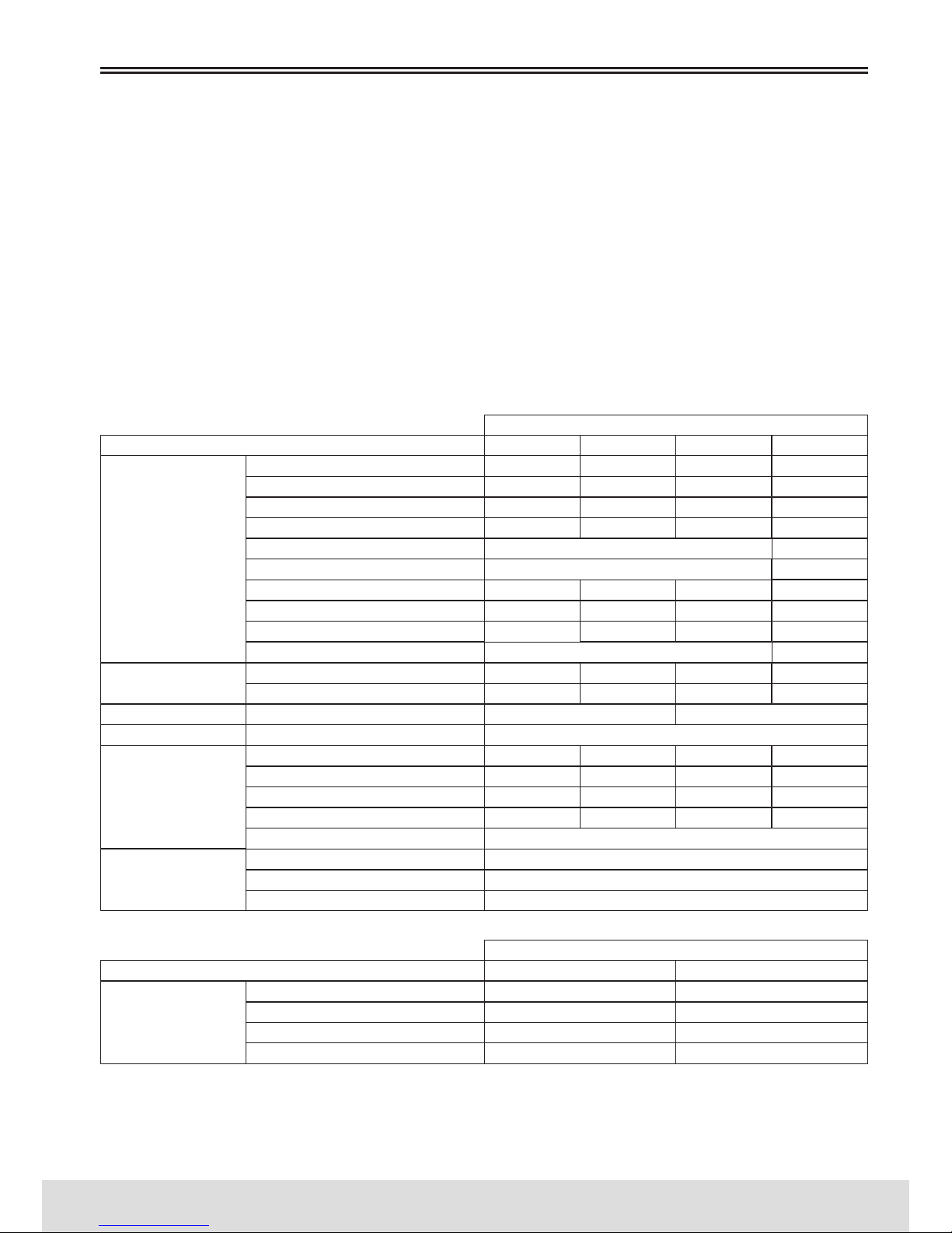
65
PORTUGUÊS
www.bergcycles.com
M (17”)
M (17”)
M (17”)
M (17”)
M (17”)
M (16,5”-17”)
M (17”)
M (16,5”-17”)
M (17”)
M (47-50cm)
M (44cm)
M (18”)
M (17”)
M (18”)
M (18”)
L (19”)
L (19”)
L (19”)
L (19”)
L (18”-19”)
L (19”)
L (18,5”-19”)
L (50-53cm)
L (48cm)
L (20”)
L (19”)
L (20”)
L (20”)
XL (21”)
XL (21”)
XL (21”)
XL (21”)
L (19”)
XL (19,5”-21”)
XL (21”)
XL (21”)
L (19”)
XL (53-56cm)
XL (53cm)
XL (21”)
S (15”)
S (15”)
S (15”)
S (15”)
S (15”)
S (15”)
S (15”)
S (44-47cm)
S (16”)
S (16”)
S (16”)
Roda 24” (Tamanho único)
Roda 24” (Tamanho único)
Roda 20” (Tamanho único)
Roda 20” (Tamanho único)
Roda 20” (Tamanho único)
Roda 20” (Tamanho único)
COUNTRY SERIES
DUNE SERIES
SIERRA SERIES
SPORTCROSS SERIES
STOCHI SERIES
STUKA SERIES
TRAIL SERIES
TRAILROCK SERIES
VERTEX SERIES
VIPER SERIES
FUEGO SERIES
FUEGO CX SERIES
E-BIKE SERIES
EASY SERIES
CLASSIC SERIES
FITNESS SERIES
PARK SERIES
TREKKING SERIES
URBAN SERIES
TRIBE SERIES
360 SERIES
FRISK SERIES
BLAST/CHARM SERIES
RACE SERIES
VORTEX SERIES
PRETTY SERIES
MONTANHA
ESTRADA
ELÉTRICA
DOBRÁVEL
LAZER
TREKKING
BMX
JÚNIOR
Use sempre luvas e capacete, de tamanho apropriado e devidamente homologados, na posição correta
(horizontal) de modo a proteger as suas mãos e cabeça em caso de queda.
Utilize sempre o seu sistema de iluminação e refletores entre o anoitecer e o amanhecer, e sempre que
as condições meteorológicas não permitam uma visibilidade suficiente, os ciclistas devem agir em conformidade com as leis nacionais em vigor no país onde estão a usar a bicicleta.
Tente permanecer sempre visível para os motoristas e motociclistas vestindo vestuário apropriado de
cor clara (de forma confortável) use refletores, circule do lado direito da via (ou esquerda no Reino
Unido), seguindo o Código da Estrada em vigor no país onde se encontra a utilizar a sua bicicleta Berg
Cycles. Sempre que o piso estiver molhado, por favor aumente a distância de travagem do veículo à sua
frente.
Guia de tamanhos de Quadro:
UTILIZAÇÃO
UTILIZAÇÃO
<165
A partir dos 9 Anos
165-175
ALTURA DO CICLISTA (cm)
JUNIORES (Anos)
175-185
A partir dos 7 Anos
185-195
REGISTO DA GARANTIA
S (14”-15,5”)
M (18”) L (20”)
TAMANHO ÚNICO
TAMANHO ÚNICO
TAMANHO ÚNICO
TAMANHO ÚNICO
TAMANHO ÚNICO
Page 66
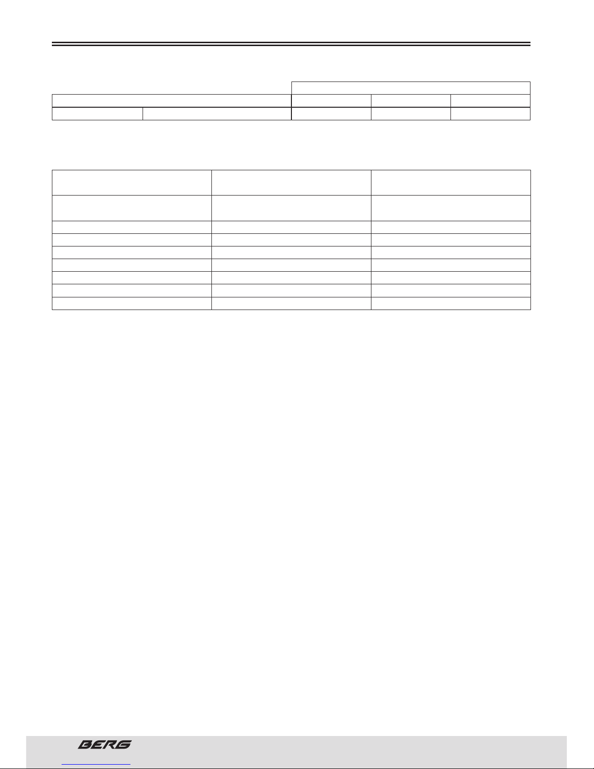
66
// MANUAL DO UTILIZADOR
PORTUGUÊS
Peso máximo autorizado e recomendado (Ciclista, bicicleta e acessórios):
REGISTO DA GARANTIA
Roda 12” (Tamanho único)
VERTEX/TRAILROCK/STUKA/TRAIL
SPORTCROSS/VOSTOK/SIERRA/ COUNTRY
FUEGO/FUEGO CX
E-BIKE
EASY
TREKKING/CLASSIC/PARK/URBAN/FITNESS
TRIBE
BLAST/CHARM (RODAS 20” E 24”)
BLAST/CHARM (RODAS 12”, 14” E 16”)
BICICLETAS DE MONTANHA
BICICLETAS DE ESTRADA
BICICLETAS ELÉTRICAS
BICICLETAS DOBRÁVEIS
BICICLETAS DE LAZER / TREKKING
BICICLETAS BMX
BICICLETAS JUNIORES
BICICLETAS DE CRIANÇA
128 kg
120 kg
135 kg
110 kg
135 kg
100 kg
85 kg
55 kg
Roda 14” (Tamanho único) Roda 16” (Tamanho único)
BLAST/CHARM SERIESCRIANÇAS
UTILIZAÇÃO
TIPO DE BICICLETA SÉRIES PESO MÁXIMO
(BICICLETA + CICLISTA + ACESSÓRIOS)
3-5 Anos 4-6 Anos 5-7 Anos
CRIANÇAS (Anos)
Page 67
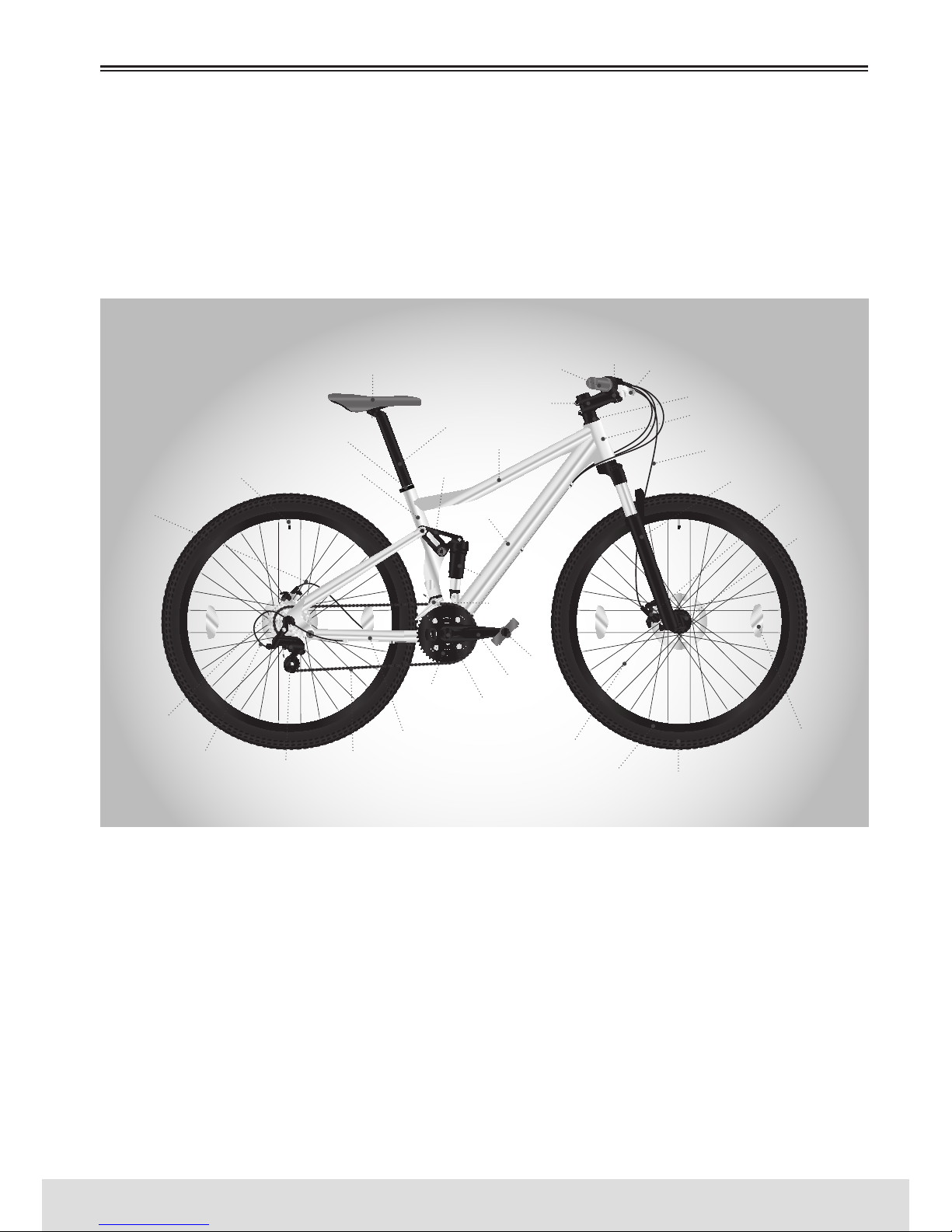
67
PORTUGUÊS
www.bergcycles.com
BICICLETAS DE MONTANHA
As bicicletas de montanha estão desenhadas para lhe proporcionar o máximo conforto sobre uma ampla
variedade de superfícies de caminhos. Guiadores mais largos e uma posição de manípulos de mudanças
conveniente tornam-nas muito fácil de controlar. Os aros e pneus mais largos concedem-lhe um andar
mais suave, com maior tração sobre superfícies rudes. O quadro e a forqueta em bicicletas de montanha
são geralmente muito mais robustos que os das bicicletas de corrida.
IDENTIFICAÇÃO DAS PARTES
PUNHO
GUIADOR
MANETE DO TRAVÃO
CAIXA DE DIREÇÃO
TUBO DE DIREÇÃO
CABO DO TRAVÃO
FORQUETA
AVANÇO
TUBO SUPERIOR
BALANÇA
TUBO INFERIOR
AMORTECEDOR
TRASEIRO
DESVIADOR
DIANTEIRO
SELIM
ESPIGÃO DO SELIM
FIXADOR DO SUPORTE DE SELIM
TUBO DO SELIMVÁLVULA
REFLETOR DA
RODA
PNEUARO
RAIO
TRAVÃO
TRASEIRO
TRAVÃO
DIANTEIRO
CUBO
DIANTEIRO
CABO DE
CONTROLO DE
MUDANÇAS
CABO DO
TRAVÃO
DESVIADOR
TRASEIRO
CORRENTE
ESCORA
PRATO
PEDALEIRO
CRANQUE
PEDAL
Page 68
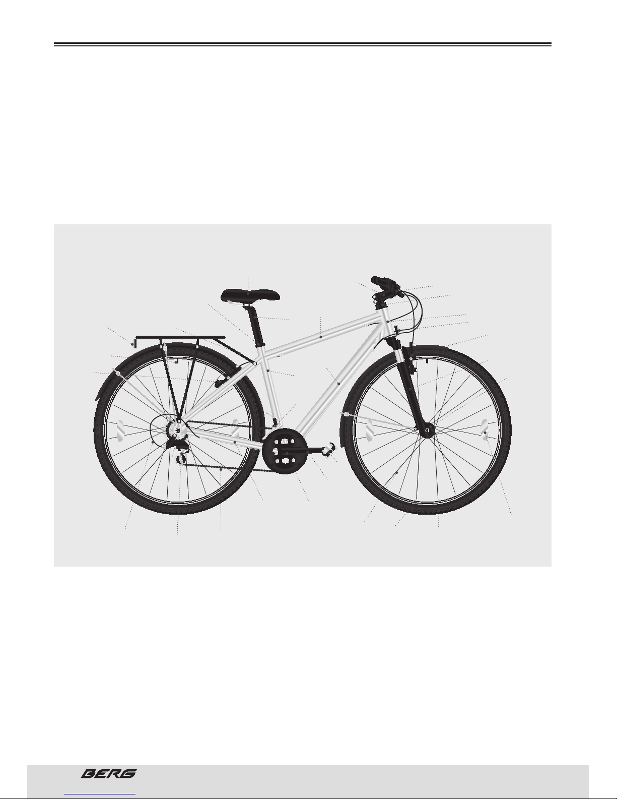
68
// MANUAL DO UTILIZADOR
PORTUGUÊS
BICICLETAS LAZER / TREKKING
De uma forma geral, estas bicicletas devem ter rodas de tamanho 28/700C, apesar de algumas possuírem pneus mais estreitos (modelos de 26”), e terem 21-27 velocidades. Combinam um selim de
comforto – estrada – montanha e a posição de guiador, com pneus mais largos e diâmetros de rodas
de bicicletas de estrada. São excelentes para o uso em ambos os pavimentos, trilhos lamacentos ou
suaves, mas não se pretende que sejam grandes bicicletas de estrada ou bicicletas de montanha. Por terem amortecedores no selim e punhos geralmente mais confortáveis proporcionam uma condução mais
confortável. São bicicletas preferidas por ciclistas profissionais ou por amadores que andam mais em
estrada, mas que querem uma agilidade e velocidade maiores do que os pneus largos de 26” oferecem.
IDENTIFICAÇÃO DAS PARTES
AVANÇO GUIADOR
CAIXA DE DIREÇÃO
TUBO DE DIREÇÃO
REFLETOR DIANTEIRO
FORQUETA
TUBO SUPERIOR
TUBO INFERIOR
DESVIADOR
DIANTEIRO
SELIM
ESPIGÃO DO
SELIM
FIXADOR DO SUPORTE DE SELIM
REFLETOR TRASEIRO
TUBO DO SELIM
VÁLVULA
REFLETOR DA
RODA
PNEU
ARO
RAIO
TRAVÃO
TRASEIRO
TRAVÃO
DIANTEIRO
CUBO
DIANTEIRO
CABO DE
CONTROLO DE
MUDANÇAS
CABO DO
TRAVÃO
DESVIADOR
TRASEIRO
CORRENTE
ESCORA
PEDALEIRO
CRANQUE
PEDAL
Page 69
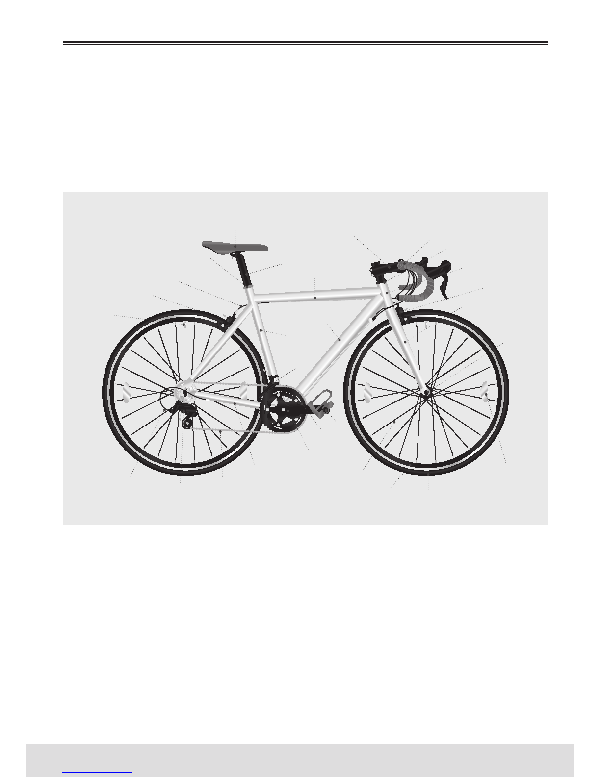
69
PORTUGUÊS
www.bergcycles.com
BICICLETAS DE ESTRADA
De uma forma geral, estas bicicletas devem ter rodas de tamanho 28/700C e 16-30 velocidades. São desenhadas para pavimentos de estrada, aumento de aerodinâmica e velocidade. Têm pneus mais suaves e
estreitos, extensores do guiador “virados para baixo”, e frequentemente têm selins finos. São bicicletas
para ciclistas que querem mais velocidade, percorrer maiores distâncias, ou um desempenho aeróbio
mais intenso, Os modelos de estrada são normalmente mais leves e com um comprimento ligeiramente
mais curto da base da roda para uma resposta mais ágil, mais rápida.
IDENTIFICAÇÃO DAS PARTES
AVANÇO GUIADOR
CAIXA DE DIREÇÃO
TUBO DE DIREÇÃO
FORQUETA
TUBO SUPERIOR
TUBO INFERIOR
DESVIADOR
DIANTEIRO
SELIM
ESPIGÃO DO SELIM
FIXADOR DO SUPORTE DE SELIM
TUBO DO SELIM
VÁLVULA
REFLETOR DA
RODA
PNEUARO
RAIO
TRAVÃO
TRASEIRO
TRAVÃO
DIANTEIRO
CUBO
DIANTEIRO
CABO DE
CONTROLO DE
MUDANÇAS
CABO DO
TRAVÃO
DESVIADOR
TRASEIRO
CORRENTE
ESCORA
PEDALEIRO
CRANQUE
PEDAL
Page 70
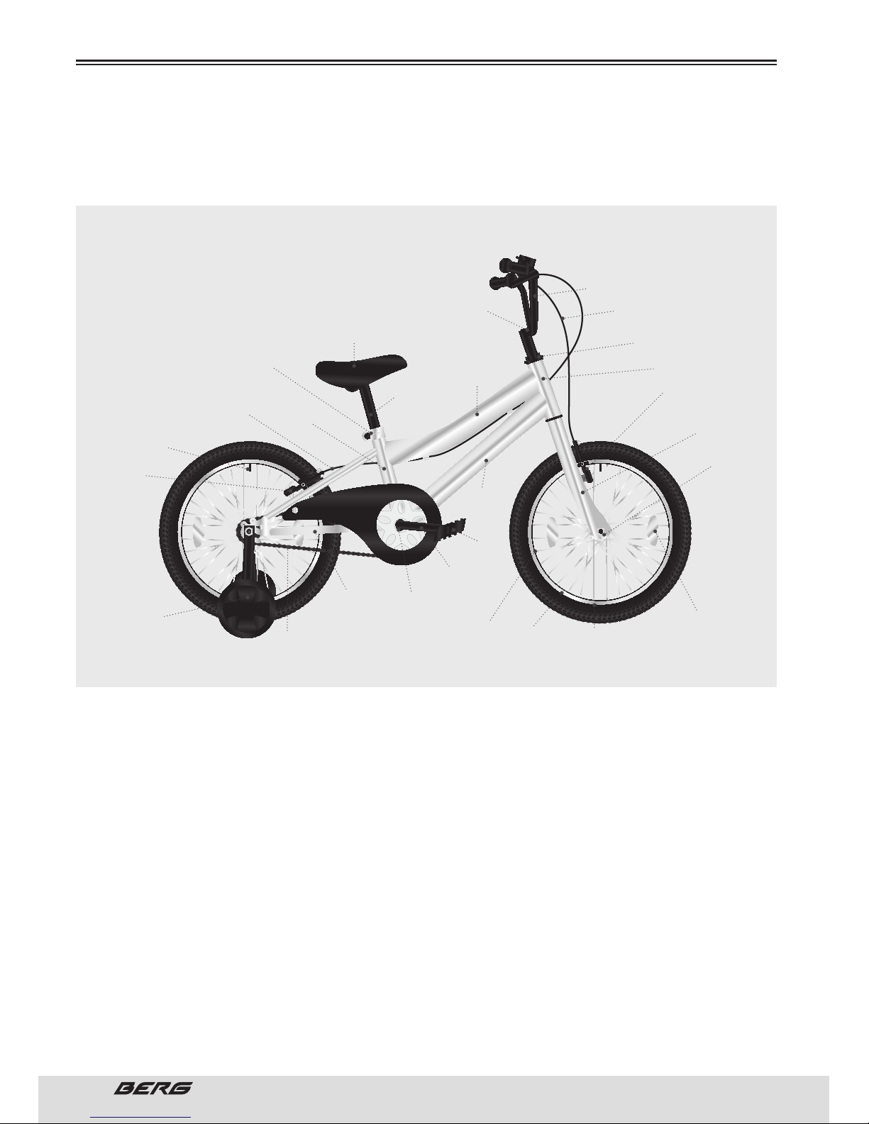
70
// MANUAL DO UTILIZADOR
PORTUGUÊS
BICICLETAS BMX/JUNIOR/CRIANÇA
São bicicletas com grande popularidade para uso geral, e adaptam-se na perfeição aos mais jovens.
São muito valorizadas pela sua construção sólida e simples e pela baixa necessidade de manutenção.
IDENTIFICAÇÃO DAS PARTES
AVANÇO
GUIADOR
CABO DO TRAVÃO
CAIXA DE DIREÇÃO
TUBO DE DIREÇÃO
FORQUETA
TUBO SUPERIOR
TUBO INFERIOR
SELIM
ESPIGÃO DO
SELIM
FIXADOR DO SUPORTE DE SELIM
TUBO DO SELIM
VÁLVULA
REFLETOR DA
RODA
PNEU
ARO
RAIO
TRAVÃO
TRASEIRO
TRAVÃO
DIANTEIRO
CUBO
DIANTEIRO
CABO DO
TRAVÃO
RODA
AUXILIAR DE
APRENDIZAGEM
CORRENTE
ESCORA
PEDALEIRO
CRANQUE
PEDAL
Page 71
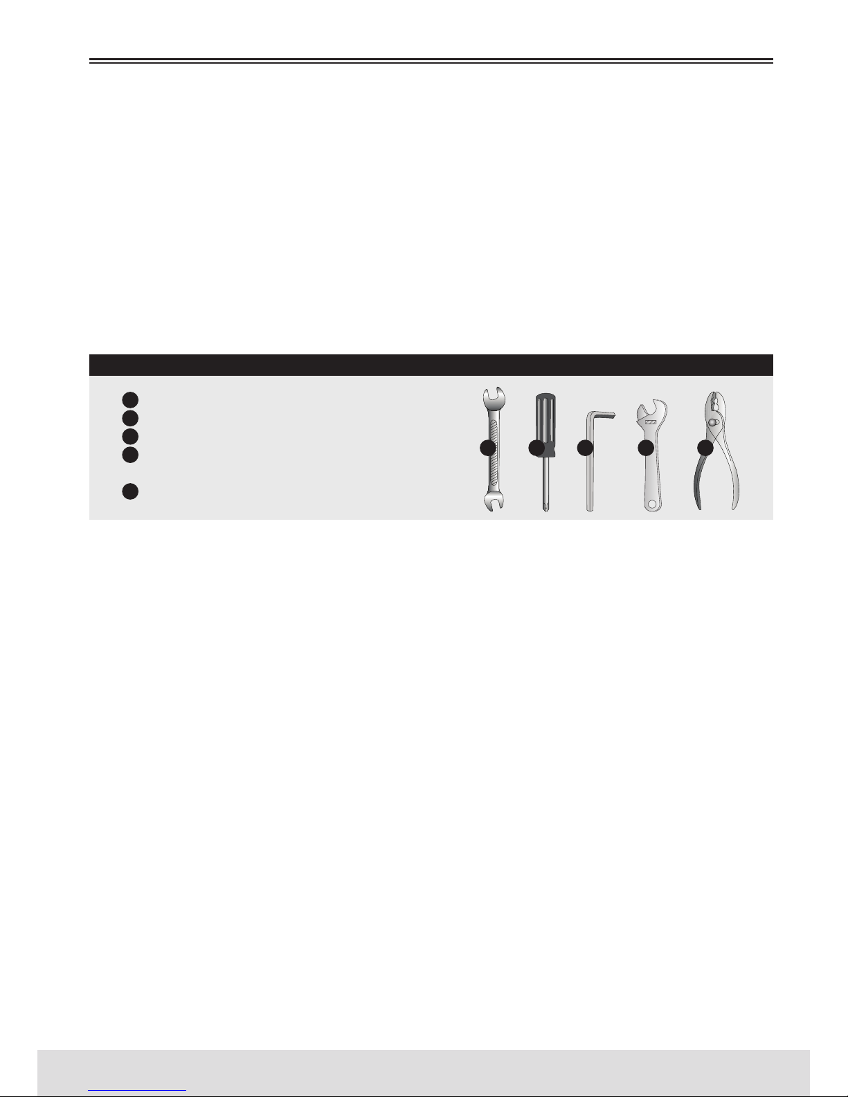
71
PORTUGUÊS
www.bergcycles.com
FERRAMENTAS NECESSÁRIAS
A sua nova bicicleta foi montada e afinada na fábrica e depois parcialmente desmontada para envio. É
provável que tenha comprado a bicicleta montada por completo e pronta a usar OU dentro de uma caixa
e parcialmente desmontada. As seguintes instruções permitem-lhe montar a bicicleta de forma a desfrutá-la durante anos. Para mais detalhes acerca da inspeção, lubrificação, manutenção e ajustes em
qualquer área, por favor, consulte as respetivas secções deste manual. Se tiver alguma incerteza quanto
à sua capacidade de montar corretamente esta unidade, por favor, consulte um especialista qualificado
antes de a utilizar. Se precisar de peças de substituição ou quiser colocar alguma questão relativa à
montagem da sua bicicleta, contacte-nos.
Para evitar lesões, este produto deve ser montado apropriadamente antes de ser utilizado.
Se comprou a bicicleta previamente montada, recomendamos que reveja todas as instruções de montagem e realize as verificações especificadas neste manual, antes de a utilizar.
FERRAMENTAS NECESSÁRIAS
Chave de Bocas
Chave de parafusos Philips
Chaves Allen de 4mm, 5mm, 6mm e 8mm
Chave-inglesa ajustável ou chaves combinadas
de 9mm, 10mm, 14mm e 15mm
Alicate para cortar cabos
ATENÇÃO
É importante que compreenda o funcionamento da sua nova bicicleta. Leia atentamente este manual e
antes de utilizar a sua bicicleta pela primeira vez, deste modo, saberá como obter um melhor rendimento
e conforto da sua nova bicicleta.
É também importante que a sua primeira utilização seja realizada num ambiente controlado, longe de
automóveis, obstáculos e outros ciclistas.
ADVERTÊNCIA GERAL
Andar de bicicleta pode ser uma atividade perigosa mesmo que o faça em ambiente controlado. A manutenção apropriada da bicicleta é da sua responsabilidade, e reduz o risco de acidentes. Este manual
contém muitas “Advertências” e “Precauções” relacionadas com as consequências da falta de manutenção e inspeção da sua bicicleta.
Muitas dessas advertências e precauções referem que “você poderá perder controlo e cair”. Qualquer
queda pode resultar em ferimentos graves, incluindo a morte, não repetiremos a advertência de uma
possível lesão ou morte, a cada vez que se mencionar o risco de queda.
NOTA ESPECIAL PARA OS PAIS
É um facto trágico que a maior parte dos acidentes de bicicletas envolva crianças. Como pai ou encarregado de educação, é responsável pelas atividades e segurança do menor.
Entre estas responsabilidades está incluída a de se assegurar que a bicicleta que o seu filho utiliza está
devidamente adaptada para a criança; que está em boas condições de reparação e funciona seguramente; que você e o seu filho tenham aprendido, compreendido e obedecido não só às leis locais aplicáveis a
veículos motorizados, bicicletas e de trânsito, mas também às normas de senso comum que implicam
utilizar a bicicleta de forma segura e responsável. No seu papel de pai, deverá ler este manual antes de
permitir que o seu filho utilize bicicleta. Assegure-se que o seu filho usa sempre um capacete apropriado
ao andar de bicicleta.
IDENTIFICAÇÃO DAS PARTES
1
2
3
4
5
1 2 3 4 5
Page 72
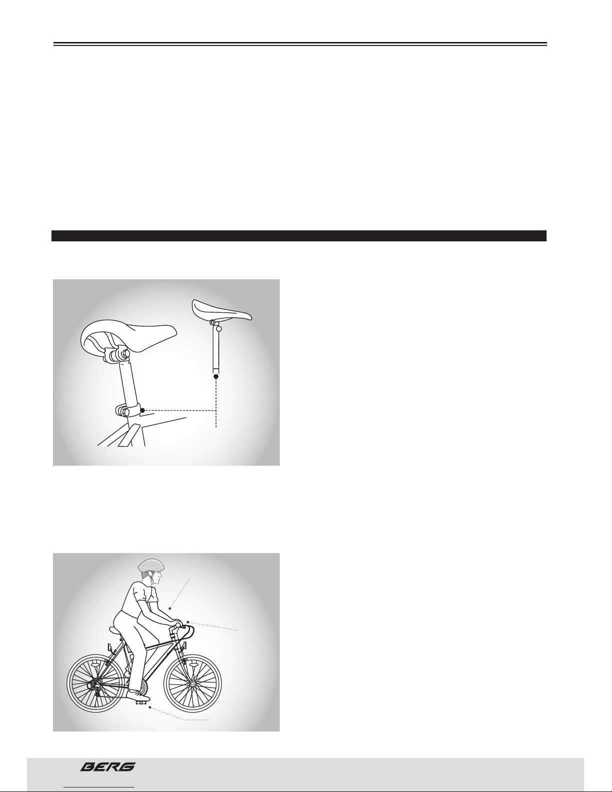
72
// MANUAL DO UTILIZADOR
PORTUGUÊS
Na escolha de uma nova bicicleta, a seleção de um tamanho de quadro é um aspeto de segurança muito
importante, a ter em conta. A maior parte dos tamanhos das bicicletas estão numa escala de tamanhos
dos quadros.
Estes tamanhos referem-se normalmente à distância entre o centro da pedaleira e a parte superior do
tubo do selim. Para uma condução segura e confortável, deve haver um afastamento de pelo menos de
2,5 a 5 cm entre a área de entre pernas do ciclista e o tubo superior do quadro da bicicleta, sendo que o
ciclista deve apoiar os pés no chão enquanto segura na bicicleta, com uma perna para cada lado.
A distância ideal varia entre tipos de bicicleta e as preferências dos ciclistas. Isto fará com que seja mais
fácil e mais seguro ficar sobre o quadro da bicicleta, quando fora do selim em determinadas situações,
tais como quando o trânsito pára repentinamente. As mulheres podem utilizar bicicletas de homem.
AJUSTES NA BICICLETA
ALTURA DO SELIM
Tendo em vista a obtenção de uma posição de utilização
o mais confortável possível, e obter a melhor eficiência
ao pedalar, a altura do selim deve ser estabelecida de
acordo com o comprimento de perna do ciclista. A altura
correta do selim não deve forçar a perna a estender em
excesso, e os quadris não devem balançar dum lado ao
outro ao pedalar.Quando sentado na bicicleta com um
dos pedais o mais abaixo possível, coloque a planta do
seu pé no mesmo. A altura do selim correta permitirá
que o joelho se flexione ligeiramente nessa posição. Se
colocar depois o calcanhar desse pé no pedal, a perna
deverá ficar quase esticada.Em nenhuma circunstância
o espigão do selim deverá ficar para além das marcas
de inserção mínima ou extensão máxima. Se o espigão
do selim se projetar para além destas marcas, o espigão do selim ou o quadro podem partir, o que poderá levá-lo a perder o controlo da bicicleta e cair. Antes da sua primeira utilização, assegure-se que
apertou o mecanismo de fixação do selim corretamente.A perda de uma braçadeira do espigão do selim
pode causar danos na bicicleta ou pode levá-lo a perder o controlo e cair. Reveja periodicamente para
ter a certeza que o mecanismo de fixação do selim está devidamente apertado. Para mais informação
consulte pág. 99.
ALCANCE
Para obter o máximo conforto, o ciclista não deverá estender-se em demasia, enquanto em andamento.
Para ajustar esta distância, a posição do selim pode ser
alterada em relação ao espigão do selim.
(Ver como ajustar a braçadeira do selim na pág. 99.)
ANTES DE USAR A BICICLETA
ALTURA DO GUIADOR
MAIS OU MENOS À
ALTURA DO SELIM
PEDAL NA POSIÇÃO
INFERIOR
BRAÇOS NÃO ESTENDIDOS
EM DEMASIA
ALTURA MÁXIMA
MARCA DE INSERÇÃO MÍNIMA
(NÃO DEVE SER VISÍVEL)
Page 73
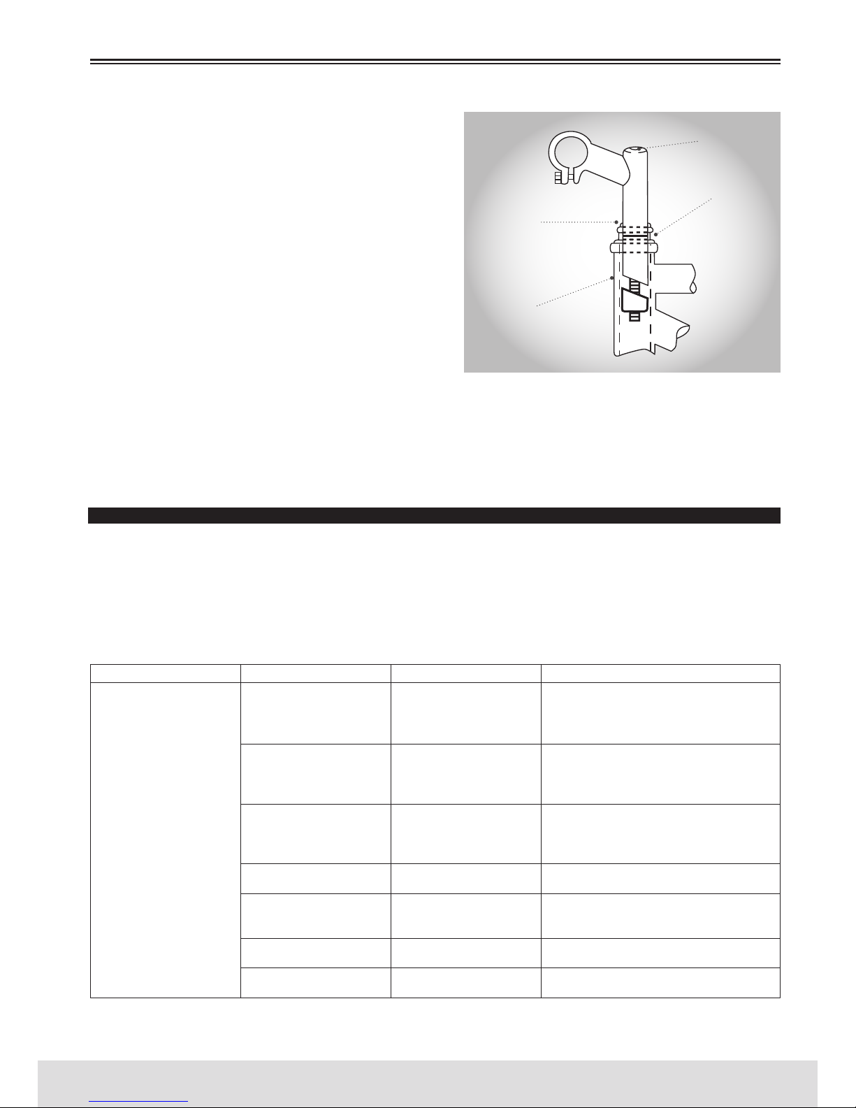
73
PORTUGUÊS
www.bergcycles.com
ALTURA DO GUIADOR
O máximo conforto é obtido, normalmente, quando a
altura do guiador está ao nível da altura do selim. Poderá experimentar diferentes alturas até encontrar a
posição mais confortável.
NOTA: As caixas de direção Aheadset não permitem
ajustar o avanço em altura.
A marca de “Inserção mínima” do avanço não deve ser
visível acima do alto da caixa de direção. Se o avanço
for prolongado além desta marca, poderá quebrar ou
danificar o tubo de direção da forqueta, o que poderá
fazer com que perca o controlo e caia.
Falhas ao apertar corretamente o parafuso de fixação
do avanço, o parafuso de fixação do guiador e os parafusos de fixação dos punhos pode comprometer a condução, levando a perder o controlo e cair. Coloque
a roda da frente da bicicleta entre as suas pernas e tente torcer o guiador/conjunto do avanço usando
apenas uma força razoável para tal.
Se conseguir torcer o avanço em direção à roda da frente, girar o guiador em direção ao avanço, ou girar
os punhos em direção ao guiador, deverá apertar os respetivos parafusos corretamente.
Para mais informação consulte pág. 97.
PLANO DE VERIFICAÇÕES DE SEGURANÇA E MANUTENÇÃO
O distribuidor local oferece a primeira revisão completa à bicicleta. Esta revisão deverá ser realizada
após as primeiras cinco horas de utilização e até um limite de dois meses após a data de compra.
A revisão poderá não ser realizada na hora.
O plano de verificações de segurança e manutenção dever ser realizado segundo os seguintes cronogramas:
CRONOGRAMA 1:
Assegure-se que o travão dianteiro e traseiro
funcionam na perfeição. Assegure-se que os cabos
de controlo de travões estão lubrificados e não
apresentam nenhum desgaste óbvio.
Assegure-se que os pneus estão insuflados à
pressão aconselhada como indicado na parte
lateral do pneu e que não apresentam desgaste
excessivo.
Assegure-se que os aros da roda rodam normal-
mente e que não apresentam nenhuma torção ób-
via.Certifique-se que estão com a tensão correta e
na posição fechada.
Assegure-se que estão ajustados e apertados
corretamente.
Certifique-se que os pedais estão presos, de forma
segura às pedaleiras. Assegure-se que os cranques
estão bem apertados ao movimento pedaleira.
Verifique que as mudanças da frente e de trás
funcionam corretamente.
Verifique que o quadro e forqueta não estão
dobrados ou partidos.
ANTES DE USAR A BICICLETA
FREQUÊNCIA COMPONENTE VERIFICAÇÃO PROCEDIMENTO
Antes de qualquer
utilização
Travão
Pneus/ Câmara-de-ar
Rodas
Direção
Pedaleiras e pedais
Mudanças
Quadro e Forqueta
Travagem e cabos
partidos
Pressão
Aro e raios/ Apertos das
rodas
Guiador e avanço
Apertos dos pedais e
pedaleiras
Mudanças e cabos
partidos
Fissuras ou dobras
PARAFUSO DE APERTO DO
AVANÇO
MARCA DE ALTURA MÁXIMA/
INSERÇÃO MÍNIMA
PARAFUSO DE FIXAÇÃO DO
GUIADOR
EXCEDENTE
2 ½ (64mm)
Page 74
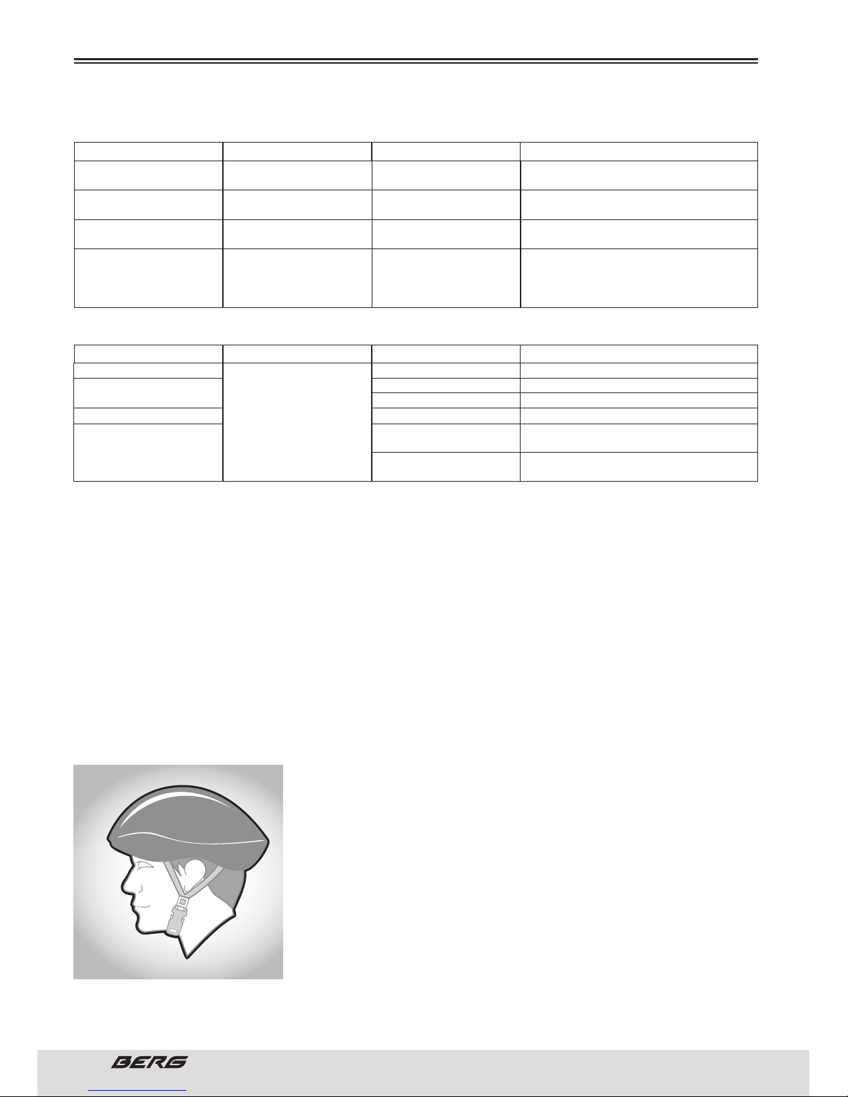
74
// MANUAL DO UTILIZADOR
PORTUGUÊS
CRONOGRAMA 2:
CRONOGRAMA 3:
NOTA:
Sempre que verificar qualquer anomalia deverá proceder à respetiva reparação.
Todas as bicicletas devem ser alvo de revisões periódicas.
A boa manutenção da bicicleta permite conservar as suas qualidades originais de utilização e segurança.
Não se esqueça de guardar a sua bicicleta num local seco, abrigado e afastado de ambientes salinos.
Não se esqueça de limpar frequentemente as cabeças dos raios e todos os parafusos da sua bicicleta.
Por norma os fabricantes usam o aço no seu fabrico para garantir componentes com a resistência adequada.
CAPACETES
Recomenda-se o uso de um capacete de segurança para ciclista que tenha um tamanho adequado,
aprovado por ANSI ou SNELL, cada vez que ande de bicicleta. Para além disso, se levar um passageiro no
assento de segurança para crianças, este deverá também usar um capacete.
O capacete correto deve: ser cómodo - ser leve - ter uma boa ventilação - ser de tamanho adequado
- cobrir a testa
Use sempre um capacete de tamanho adequado, que lhe proteja a testa, enquanto andar de bicicleta. Muitos países requerem dispositivos
de segurança específicos. Você é responsável por conhecer as leis do
país onde utiliza a sua bicicleta e por cumprir todas as leis aplicáveis,
incluindo equipar-se devidamente e à sua bicicleta, segundo os requisitos legais. Os refletores são dispositivos de segurança importantes,
desenhados como parte integrante da bicicleta. Estes refletores são
criados de forma a captar e refletir as luzes das ruas e dos automóveis
de forma a ajudá-lo a ser visto e reconhecido como um ciclista em
movimento. Inspecione os refletores e os seus suportes de montagem
com regularidade para garantir que estão limpos, direitos, em perfeitas
condições e montados de forma segura. Peça ao seu revendedor que substitua os refletores danificados
e endireite ou prenda aqueles que estiverem dobrados ou soltos.
ANTES DE USAR A BICICLETA
Limpar e depois pincelar ou salpicar
3 gotas de lata de óleo
Desmontar e lubrificar
Lubrificar
Desmontar e Lubrificar
Limpar/lubrificar
Apertar
Lubrificar c/óleo de teflon
Limpeza e lubrificação geral no fornecedor
Mudança de óleo e lubrificação c/óleo
de teflon no fornecedor
Inspeção e substituição completa
(vedantes/óleo) no fornecedor
FREQUÊNCIA
FREQUÊNCIA
COMPONENTE
COMPONENTE
LUBRIFICANTE
ÁREA
PROCEDIMENTO
PROCEDIMENTO
Semanalmente
Mensalmente
Cada 6 meses
Anualmente
Após qualquer utilização
Depois de 25 horas
Depois de 50 horas
Depois de 100 horas
Corrente/Desviador
Manetes travão
Manípulos de mudança
Cabos de travão e mudança
Cubos e carretos
Pedaleiras/Pedais
Rolamentos da roda
Caixa de direção
Espigão de selim
Suspensão
Amortecedor
Lubrificante ou óleo
ligeiro para correntes
Gordura à base de lítio
Lubrificante ou óleo
ligeiro para correntes
Gordura à base de lítio
Pernas e zona do vedante
Aperto dos parafusos
Zona do vedante
Funcionamento suspensão
Bloqueio ou travel adjust
abaixo da tampa
Funcionamento suspensão
Page 75
75
PORTUGUÊS
www.bergcycles.com
ANDAR DE BICICLETA DE FORMA SEGURA
REGRAS GERAIS
Quando andar de bicicleta, obedeça às mesmas regras de trânsito que todos os outros veículos, incluindo
ceder passagem a peões e parar no sinal vermelho e sinais de Stop.
Para obter mais informação, contacte as autoridades de trânsito rodoviário do seu país.
Guie de maneira previsível e em linha reta. Nunca guie em direção oposta ao trânsito.
Utilize os sinais de mão corretos para indicar mudanças de direção ou paragens.
Guie de forma defensiva. Os demais utilizadores das estradas podem ter dificuldade em vê-lo.
Concentre-se no caminho que tem à sua frente. Evite buracos, gravilha, zonas molhadas do caminho,
manchas de óleo, beiras dos passeios, lombas, grelhas de escoamento e outros obstáculos.
Passe os carris ferroviários formando um ângulo de 90 graus ou a pé, com a bicicleta pelo braço.
Esteja preparado para imprevistos, portas de automóveis que se abram repentinamente ou automóveis
que saiam de marcha atrás de caminhos de acesso não visíveis.
Seja extremamente cuidadoso nos cruzamentos e quando se preparar para ultrapassar outros veículos.
Familiarize-se com todas as características da bicicleta. Pratique mudanças de velocidade, travagens e
ao uso dos pedais de encaixe, se os tiver montados.
Se usar calças largas, utilize ganchos para as pernas ou fivelas elásticas para evitar que se prendam
na corrente. Use indumentária apropriada para andar de bicicleta e evite calçado que deixe os dedos a
descoberto.
Não leve cargas ou passageiros que interfiram com a sua visibilidade ou com o controlo da bicicleta. Não
utilize elementos que possam restringir a sua audição.
Não bloqueie os travões. Ao travar, utilize sempre o travão traseiro primeiro, e depois o dianteiro. O
travão dianteiro é mais forte e se não for aplicado corretamente, é possível que perca o controlo e caia.
Mantenha uma distância cómoda dos demais ciclistas, veículos e objetos quando travar. As distâncias e
forças relacionadas com uma travagem segura dependem das condições climatéricas.
TEMPO HÚMIDO
NÃO É RECOMENDÁVEL ANDAR DE BICICLETA EM TEMPO DE CHUVA
Em tempo de chuva deverá ter cuidados redobrados.
Trave com mais antecedência, pois para parar necessita de uma distância maior.
Diminua a velocidade, evite travagens repentinas e faça as curvas com mais precaução.
Opte por uma posição em que fique mais visível na estrada.
Use roupa com refletores e utilize as luzes de segurança.
Os buracos e as superfícies escorregadias como as marcas das estradas e os carris ferroviários tornamse ainda mais perigosas quando estão molhadas.
ANDAR DE BICICLETA À NOITE
NÃO É RECOMENDÁVEL ANDAR DE BICICLETA À NOITE
Certifique-se de que a bicicleta está equipada com um conjunto completo de refletores limpos e colocados corretamente.
Para mais informação consulte a pág. 95.
Utilize um conjunto de iluminação que funcione apropriadamente, composto por uma lâmpada dianteira
de cor branca e uma traseira de cor vermelha. Se utilizar luzes a bateria, assegure-se de que as baterias
estão recarregadas. Algumas luzes traseiras disponíveis têm um mecanismo intermitente que aumenta
a visibilidade. Use roupa refletora e de cores claras. Utilize a bicicleta de noite apenas se necessário.
Diminua a velocidade e use caminhos conhecidos com iluminação, se possível.
ANTES DE USAR A BICICLETA
Page 76
76
// MANUAL DO UTILIZADOR
PORTUGUÊS
TÉCNICA DE PEDALAR
Coloque a parte anterior da planta do pé no centro do pedal.
Ao pedalar, certifique-se de que os seus joelhos estão paralelos em relação ao quadro da bicicleta.
Para amortizar o impacto, mantenha os cotovelos ligeiramente dobrados.
Aprenda a utilizar as mudanças apropriadamente.
Para mais informação consulte as pág. 77 à 79.
TÉCNICA PARA MONTANHA
Coloque uma mudança mais baixa antes de subir e continue a baixar as mudanças, sempre que necessário, para manter a velocidade da pedalada.
Se estiver na mudança mais baixa e se está a esforçar-se, coloque-se de pé sobre os pedais. Assim,
obterá uma maior potência de cada vez que pedalar.
Na descida, utilize as mudanças mais altas para evitar um pedalar rápido.
Não ultrapasse uma velocidade cómoda, mantenha o controlo e tenha especial cuidado.
TÉCNICA PARA CURVAR
Trave ligeiramente antes de fazer as curvas e prepare-se para inclinar o corpo na curva.
Mantenha o pedal que ficar na parte de dentro da curva, numa posição a 12 horas, e coloque o joelho
dessa perna virado ligeiramente na direção para a qual está a curvar.
Mantenha a outra perna direita, não pedale nas curvas rápidas ou apertadas.
REGRAS PARA CRIANÇAS
Para evitar acidentes, ensine às crianças boas técnicas para andar de bicicleta enfatizando a parte de
segurança desde cedo. As crianças devem ser supervisionadas por um adulto,
1. Use sempre um capacete de tamanho adequado.
2. Não treine em autoestradas ou em estradas.
3. Não ande de bicicleta em ruas com muito trânsito.
4. Não ande de bicicleta de noite.
5. Obedeça a todas as regras de trânsito, especialmente aos sinais de stop e aos sinais vermelhos.
6. Esteja atento aos outros veículos que circulam atrás ou perto de si.
7. Antes de entrar numa rua: pare, olhe para a direita, depois para a esquerda e novamente para a direita
para ver o trânsito. Se não vir nenhum veículo, avance.
8. Se estiver a fazer uma descida, seja extremamente cuidadoso. Diminua a velocidade utilizando os
travões e mantenha o controlo da direção.
9. Nunca tire as mãos do guiador ou os pés dos pedais, ao descer uma encosta.
A Comissão de Segurança para a Proteção do Consumidor adverte-o que andar em bicicletas com rodas
de diâmetro pequeno a velocidades excessivas, pode causar instabilidade e não é recomendável.
Deve-se explicar às crianças todos os possíveis riscos que estes correm ao andar de bicicleta, e o tipo
de comportamento correto de condução, antes de permitir que andem nas ruas.
Não deixe ao acaso, experiências e erros.
FUNCIONAMENTO DAS MUDANÇAS
As maiorias das bicicletas multivelocidades atuais estão equipadas com aquilo que se conhece como
mudanças ou desviadores. Funcionam utilizando um sistema de manípulos e mecanismos para desviar
a tração da corrente entre as mudanças e carretos de diferente tamanho. O objetivo das mudanças de
velocidade é permitir-lhe manter um pedalar regular e constante em diversas condições. Isto significa
que se cansará menos ao pedalar, sem exercer uma pressão desnecessária ou pedalar rapidamente ao
descer uma encosta. As bicicletas têm uma ampla variedade de configurações de mudanças de velocidade, desde 6 a 30 velocidades. Uma bicicleta de 5 ou 6 velocidades terá uma só roda dentada dianteira
ANTES DE USAR A BICICLETA
Page 77
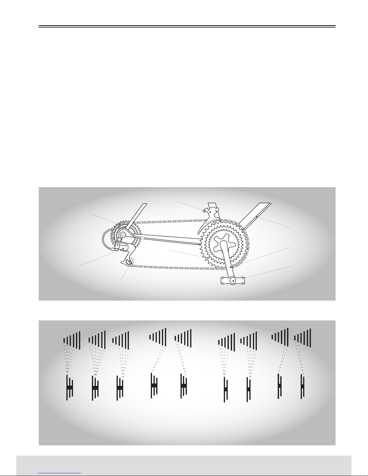
77
PORTUGUÊS
www.bergcycles.com
(prato), um desviador traseiro e 5 ou 6 carretos no cubo traseiro.
As bicicletas com mais velocidades também têm um desviador dianteiro, um prato dianteiro com 2 ou 3
rodas dentadas e até 10 carretos no cubo traseiro.
PRINCÍPIOS OPERATIVOS DOS DESVIADORES
Os princípios operativos são os mesmos, independentemente do número de velocidades.
O desviador dianteiro funciona através do manípulo de mudanças esquerdo, e o desviador traseiro através do manípulo de mudanças direito. Deve pedalar para a frente para que as mudanças funcionem. Não
pode mudar as mudanças com os desviadores se estiver parado ou pedalando para trás. Antes de mudar
de velocidade, reduza a pressão ao pedalar. Para conseguir uma mudança de velocidade mais suave ao
aproximar-se de uma montanha, passe para uma mudança de velocidade mais baixa, antes que a velocidade de pedalar diminua demasiado. Ao chegar a uma paragem, primeiro passe para uma mudança
mais baixa de modo que lhe seja mais fácil começar a pedalar novamente. Se, depois de selecionar uma
nova posição, escutar um leve ruído de fricção das mudanças dianteiras ou traseiras, ajuste suavemente
a mudança apropriada utilizando os tensores até que o ruído desapareça. Para conseguir um rendimento
ótimo e uma maior duração de vida da corrente, recomenda-se evitar o uso de combinações extremas
das posições das mudanças durante períodos prolongados.
COMBINAÇÕES DE MUDANÇAS NO PRATO/CARRETOS TRASEIROS RECOMENDADAS
ANTES DE USAR A BICICLETA
CABO DE CONTROLO DO
DESVIADOR
DESVIADOR DIANTEIRO
DESVIADOR TRASEIRO
CARRETO DA RODA
LIVRE
TRANSMISSÃO
ROLDANA GUIA
PRATOS DIANTEIROS
CRANQUE
PEDAL
ALTO ALTO
3
2
1
2
1
MÉDIO BAIXO BAIXOESTAS COMBINAÇÕES NÃO SÃO
RECOMENDÁVEIS PARA ALCANÇAR
UM RENDIMENTO ÓTIMO
ESTAS COMBINAÇÕES NÃO SÃO
RECOMENDÁVEIS PARA ALCANÇAR
UM RENDIMENTO ÓTIMO
Page 78
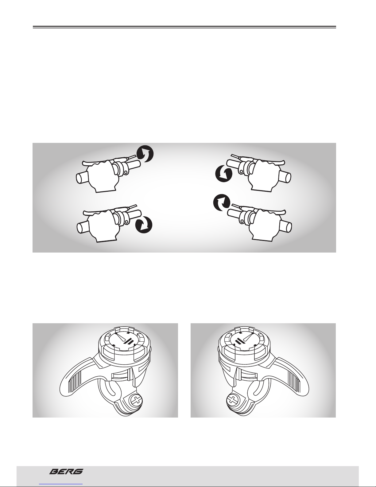
78
// MANUAL DO UTILIZADOR
PORTUGUÊS
FUNCIONAMENTO DOS MANÍPULOS DE PUNHO
Algumas bicicletas vêm atualmente com um mecanismo de mudanças denominado Grip Shift, construído
dentro dos punhos e que não utiliza manípulos separados. O mecanismo está construído na parte interna
do punho, de modo a ficar entre o dedo polegar e o indicador. Para selecionar uma mudança mais baixa,
rode o punho direito em direção a si para engatar um carreto traseiro maior. Poderá realizar as mudanças, uma de cada vez, movendo com um clique o Grip Shift, ou mediante múltiplas mudanças ao rodá-lo
continuamente. Ao rodar o punho esquerdo para a frente ou em direção oposta a si, poderá selecionar
um prato mais pequeno. Para selecionar uma mudança mais alta, rode o punho direito para a frente ou
em direção oposta a si para engatar um carreto traseiro mais pequeno. Para engatar um prato dianteiro
maior, rode o punho esquerdo em direção a si. As mudanças simples podem ser efetuadas rodando um
clique de cada vez, e as mudanças múltiplas com um rodar maior.
MANÍPULOS DE MUDANÇAS DE POLEGAR
Algumas bicicletas de montanha estão equipadas com manípulos de mudanças montados na parte superior do guiador e que se operam com o dedo polegar. Para selecionar uma mudança mais baixa e mais
leve, troque para um carreto traseiro maior e um prato mais pequeno. Puxe o manípulo esquerdo para
trás para mover o desviador dianteiro e empurre o manípulo direito para a frente para mover o desviador
traseiro. Para selecionar uma mudança mais alta e mais pesado, troque para um carreto traseiro mais
pequeno e um prato maior. Empurre o manípulo esquerdo para a frente para o desviador dianteiro, e
puxe o manípulo direito para trás para o desviador traseiro.
MUDANÇA SUPERIOR (MAIS PESADO)
CARRETO TRASEIRO PEQUENO
PRATO GRANDE
MANÍPULO DA MÃO ESQUERDA PARA A FRENTE
MANÍPULO DA MÃO DIREITA PARA TRÁS
MUDANÇA INFERIOR (MAIS LEVE)
CARRETO TRASEIRO GRANDE
PRATO PEQUENO
MANÍPULO DA MÃO ESQUERDA PARA TRÁS
MANÍPULO DA MÃO DIREITA PARA A FRENTE
ANTES DE USAR A BICICLETA
MUDANÇA BAIXA DIANTEIRA MUDANÇA BAIXA TRASEIRA
MUDANÇA ALTA DIANTEIRA
MANÍPULO DA MÃO ESQUERDA MANÍPULO DA MÃO DIREITA
MUDANÇA ALTA TRASEIRA
Page 79
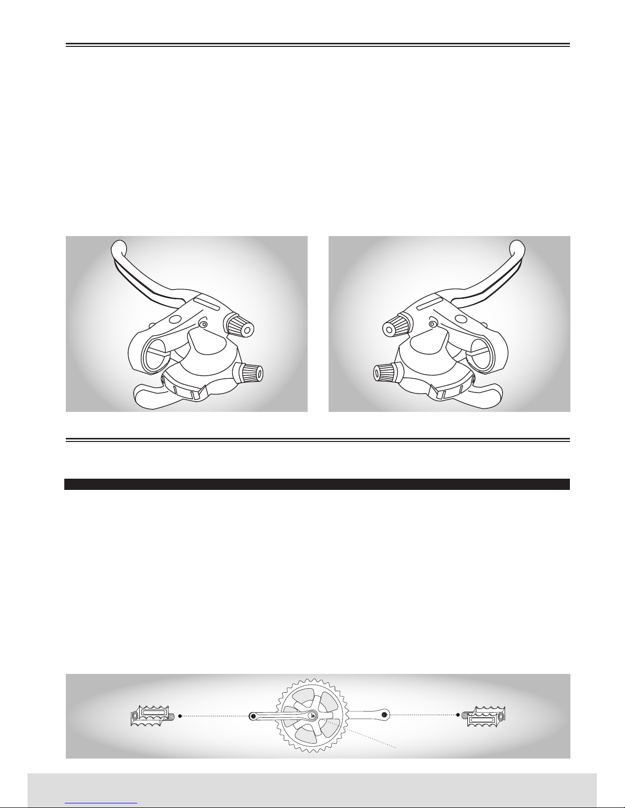
79
PORTUGUÊS
www.bergcycles.com
MANÍPULOS DE MUDANÇAS POR BAIXO DO GUIADOR
Atualmente, a maioria das bicicletas de montanha o conjunto de manípulos de mudanças está montado na parte inferior do guiador e é composto por dois manípulos que se operam com o dedo polegar e
indicador. Para selecionar uma mudança mais baixa, empurre o manípulo direito maior (de baixo) com
o polegar para engatar um carreto traseiro maior. Um empurrão firme muda a corrente de carreto, e
se continuar a empurrar, a corrente mover-se-á pelos vários carretos da cassete. Ao puxar o manípulo
esquerdo mais pequeno (de cima) com o indicador, a corrente mover-se-á de um prato maior para um
mais pequeno. Para selecionar uma mudança mais alta, puxe o manípulo direito mais pequeno (de cima)
com o dedo indicador para engatar um carreto traseiro mais pequeno. Ao empurrar o manípulo esquerdo
maior (de baixo) com o polegar, a corrente mover-se-á de um prato mais pequeno para um maior. Para
obter instruções adicionais, consulte a pág. 77.
PEDAIS E PEDALEIROS
Procure as letras “R” para a direita e “L”. para a esquerda, estampadas no eixo de cada pedal. Inicie a
instalação de cada pedal manualmente para evitar que as porcas se danifiquem. Aperte com uma chave
combinada de 15mm. Tenha em conta que o pedal direito é preso à pedaleira do lado do prato enroscando
para a direita (no sentido dos ponteiros do relógio). O pedal esquerdo é preso à outra pedaleira enroscando para a esquerda (no sentido contrário aos ponteiros do relógio). É muito importante verificar que
o jogo de pedaleiras está corretamente apertado e ajustado, e com a rigidez apropriada antes de andar
na sua bicicleta. As pedaleiras novas podem ficar com folgas inicialmente. Uma vez instalados os pedais,
tire as capas protetoras de pó do centro de cada cranque da pedaleira. Com uma chave de caixa de 14mm
ou chave Allen 8mm aperte as porcas/parafusos do eixo firmemente (aprox. 39.5 N.m) e volte a colocar
as capas protetoras de pó. Se apertar o pedal errado a uma pedaleira poder-se-ão danificar as porcas
do pedal e provocar danos irreparáveis. Antes de usar a bicicleta pela primeira vez, certifique-se de que
os pedais estão corretamente apertados.
ANTES DE USAR A BICICLETA
MONTAGEM
MANÍPULO DA MÃO ESQUERDA MANÍPULO DA MÃO DIREITA
INSIRA SOMENTE O PEDAL DIREITO
INSIRA SOMENTE O PEDAL ESQUERDO
CAPA PROTETORA DE PÓ
IMPORTANTE!IMPORTANTE!
Page 80
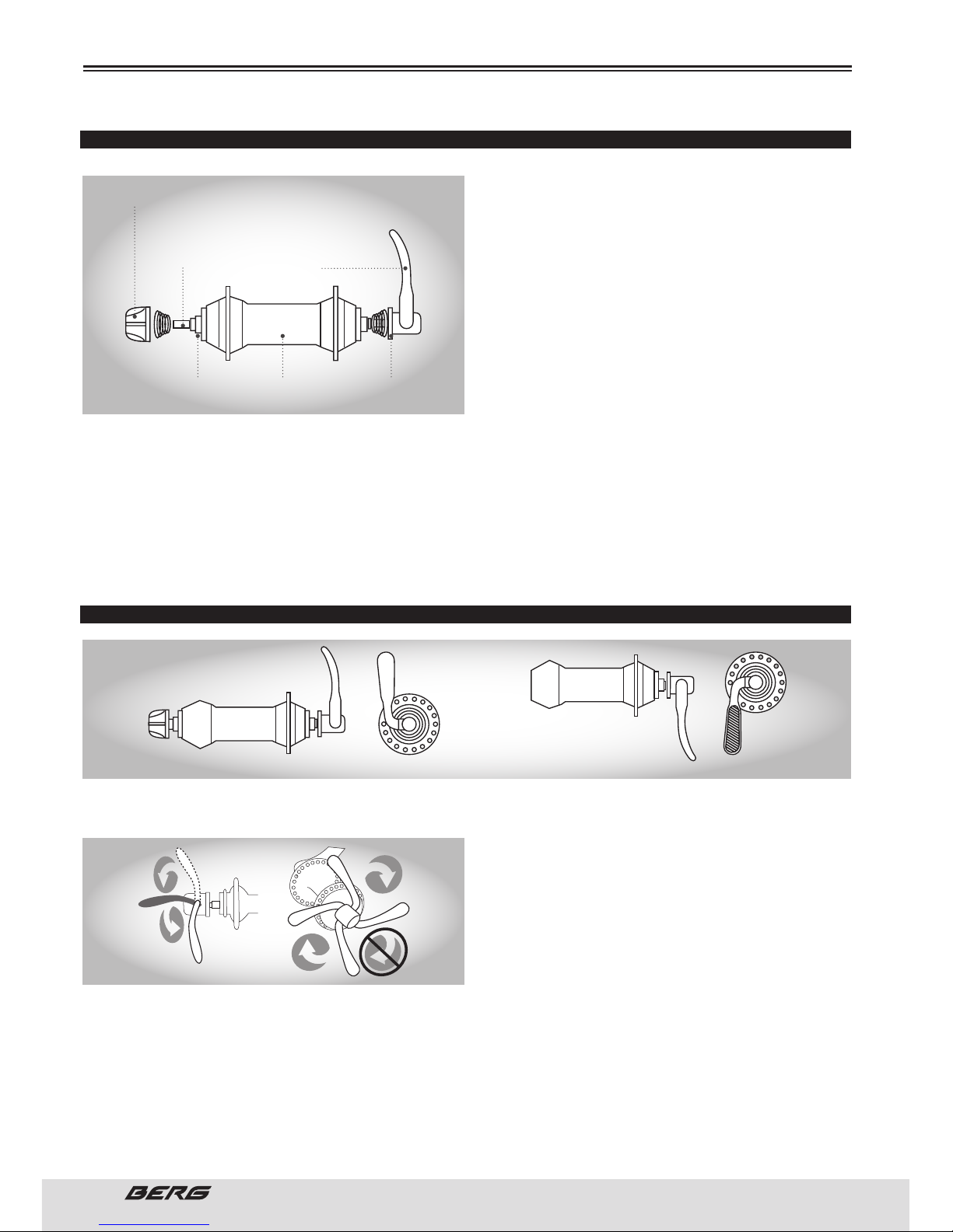
80
// MANUAL DO UTILIZADOR
PORTUGUÊS
MONTAGEM
RODA DIANTEIRA E TRASEIRA
Inspecione o cubo da roda antes de o ajustar à
forqueta, girando o eixo enroscado. Deve fazê-lo
suavemente, sem movimento lateral. Insira a roda
dianteira entre as ponteiras da forqueta. Aperte as
porcas usando a chave apropriada de 14 ou 15mm.
Gire a roda para verificar se está bem colocada. Algumas bicicletas têm eixos de rodas que incorporam um mecanismo de abertura rápida (QR). Isto
permite tirar a roda facilmente, sem necessidade
de ferramentas. O mecanismo utiliza um parafuso
largo oco com uma porca de ajuste numa extremidade e uma alavanca que opera um tensor na outra
extremidade.Se a roda é colocada com um eixo de
abertura rápida, rode a porca de ajuste para que a alavanca e bloqueio se mova para a posição de fechado com um movimento firme. A meio do caminho para a posição de fechado da alavanca de abertura
rápida, deve começar a sentir uma certa resistência a este movimento. Não aperte a abertura rápida
utilizando a alavanca como uma porca de asa. Se a alavanca de abertura rápida se desloca para a posição
de fechado sem resistência, a força de fixação é insuficiente.
Mova a alavanca de abertura rápida para a posição de aberto, aperte a porca de fixação da alavanca de
abertura rápida e coloque novamente a alavanca na posição de fechado.
POSICIONAMENTO CORRECTO DA ALAVANCA DE ABERTURA RÁPIDA
1. Para colocá-lo, rode a alavanca para a posição de aberto de maneira a que a parte curva fique em
direção oposta à bicicleta.
2. Enquanto segura a alavanca com uma mão,
aperte a porca de fixação até que esta pare.
3. Rode a alavanca para a posição de fechado.
Quando a alavanca estiver a meio caminho para a
posição de fechado, deve sentir uma certa resistên-
cia para avançar desde esse ponto. Se a resistência
não é grande, abra a alavanca e aperte a porca de
fixação no sentido dos ponteiros do relógio.
4. Continue a rodar a alavanca até à posição de fechado, de maneira a que a parte curva da alavanca
fique de frente para a bicicleta.
5. A roda está bem segura quando as superfícies dentadas das partes de fixação da alavanca de abertura
rápida começam a chegar às superfícies do quadro/forqueta da bicicleta.
6. Tenha em conta que o procedimento é o mesmo que utiliza aquando da colocação do mecanismo de
libertação rápida do espigão do selim.
7. Coloque a bicicleta em posição vertical utilizando o pé de apoio para a suportar.
PORCA DE FIXAÇÃO
EIXO DA ALAVANCA
DE ABERTURA
RÁPIDA
ALAVANCA DE
ABERTURA RÁPIDA
MOLACUBOEIXO DO CUBO
POSIÇÃO FECHADO POSIÇÃO ABERTO
Page 81
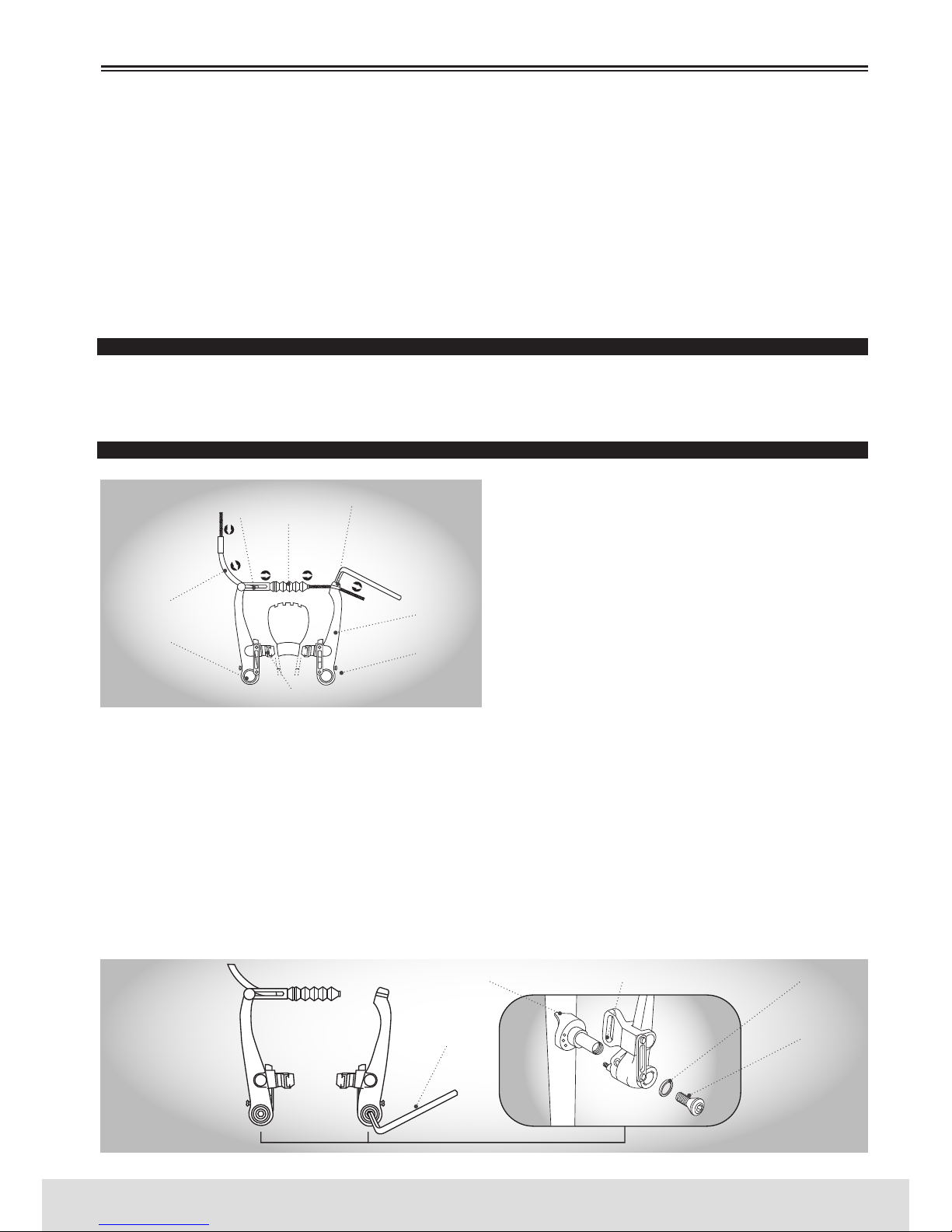
81
PORTUGUÊS
www.bergcycles.com
Se conseguir fechar totalmente a alavanca de abertura rápida sem envolver os seus dedos nas pás da
forqueta para rodá-la, e se a alavanca não lhe deixa uma marca clara na palma da sua mão, a tensão não
é suficiente. Abra a alavanca, rode o ajuste e tente novamente. Continue até que a alavanca de abertura
rápida se feche corretamente. Os dispositivos de retenção secundários não substituem o aperto correto
da alavanca de abertura rápida. Se o mecanismo de abertura rápida não é apertado corretamente, a roda
poderá ficar com folgas ou soltar-se, o que poderá levá-lo a perder o controlo e cair, provocando lesões
sérias ou até morte. Para a roda traseira, o procedimento é semelhante, tendo apenas o cuidado de pousar a corrente na velocidade em que desmontou a roda (verifique o mostrador do seletor de velocidades)
Veja também as pág. 104 à 107.
TRAVÕES
Verifique com que tipo de travões a sua bicicleta está equipada e consulte as instruções de montagem apropriadas. Para obter mais informação sobre o ajuste e manutenção dos travões, consulte as pág. 81 à 84.
TRAVÕES V-BRAKE
Se ainda não estiverem montados, tire o macarronete
do travão da caixa de partes e deslize o cabo através da abertura maior. A espiral do cabo assentará na
extremidade do macarronete. Deslize o cabo através
da guia do cabo na extremidade do braço de travão
esquerdo, o que fará com que o macarronete entre na
guia. Deslize a bota do cabo do travão sobre o cabo e
posicione-a entre ambos os braços de travão. Depois,
desaperte a cavilha de fixação de 5mm na extremidade do braço do travão direito e deslize o cabo por
baixo da anilha de retenção. Tire toda a tensão do cabo
certificando-se que há uma distância de 39mm ou mais entre a extremidade da guia e o começo da cavilha
de fixação. Quando o cabo estiver ligado aos braços de travão, aperte a manete de travão várias vezes, verificando a posição das sapatas do travão no aro. As sapatas de travão devem estar a 1mm de distância do aro.
Se a sua bicicleta tiver V-Brake não se esqueça de o apertar antes de a usar. Quando a manete do travão é
apertada, a sapata de travão deve tocar o aro (nunca o pneu) com o calço do travão dianteiro tocando
ligeiramente o aro antes do calço do travão traseiro. Isto é o que se chama de .inclinar para a frente. a
sapata de travão. Se não se obtiver esta posição, devem realizar-se ajustes à sapata de travão. Desaperte os parafusos da sapata do travão e coloque novamente a sapata. Talvez seja necessário realizar
vários ajustes à sapata e ao cabo até obter a posição desejada.
1. Se a sua bicicleta está equipada com travões de estilo V, insira o corpo do travão no orifício central
da mola no cubo de montagem do quadro e depois ligue o corpo do travão ao quadro com o parafuso de
fixação.
MONTAGEM
PARAFUSO DE FIXAÇÃO
PINO REGULADOR
ORIFÍCIO DA MOLA
CHAVE ALLEN DE
5mm
ANILHA
GUIA EXTERIOR DO
CABO
CABO DO TRAVÃO
CAVILHA DO PIVÔ
PARAFUSO DE TENSÃO
BRAÇO DO TRAVÃO
SAPATA DO TRAVÃO
BOTA DO CABO
DO TRAVÃO
CAVILHA DE FIXAÇÃO
Page 82
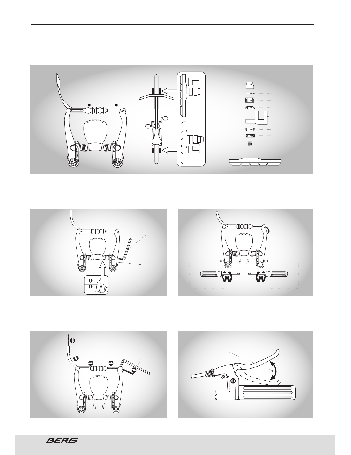
82
// MANUAL DO UTILIZADOR
PORTUGUÊS
2. Enquanto segura a sapata de encontro ao aro, ajuste o grau de protuberância da sapata intercalando
a posição das anilhas B (isto é, 6 mm e 3mm) de modo que a dimensão A se mantenha a 39mm ou mais.
3. Enquanto segura a sapata contra o aro, aperte
a porca de fixação da sapata.
Calibre com os parafusos de mola ajustável.
4. Passe o cabo interno através da guia do cabo interno. Coloque o cabo deixando um espaço livre de
1mm entre cada calço de travão e o aro, aperte o parafuso de fixação do cabo.
6. Prima a manete do travão aproximadamente 10
vezes à altura do punho, para verificar que tudo está
a funcionar corretamente e que o espaço livre da sapata é o correto, antes de utilizar os travões.
MONTAGEM
PORCA DE FIXAÇÃO
DA SAPATA
ANILHA
6mm B ANILHA
3mm B ANILHA
A ANILHA
39mm OU MAIS
A
A ANILHA
LIGAÇÃO DE FIXAÇÃO
DA SAPATA
CHAVE ALLEN DE
5mm
CHAVE ALLEN DE
5mm
PORCA DE FIXAÇÃO
DA SAPATA
1mm
1mm
2 2 11
1mm
1mm
PARAFUSO DE AJUSTE
DA TENSÃO DA MOLA
PRIMA APROXIMADAMENTE 10 VEZES
Page 83
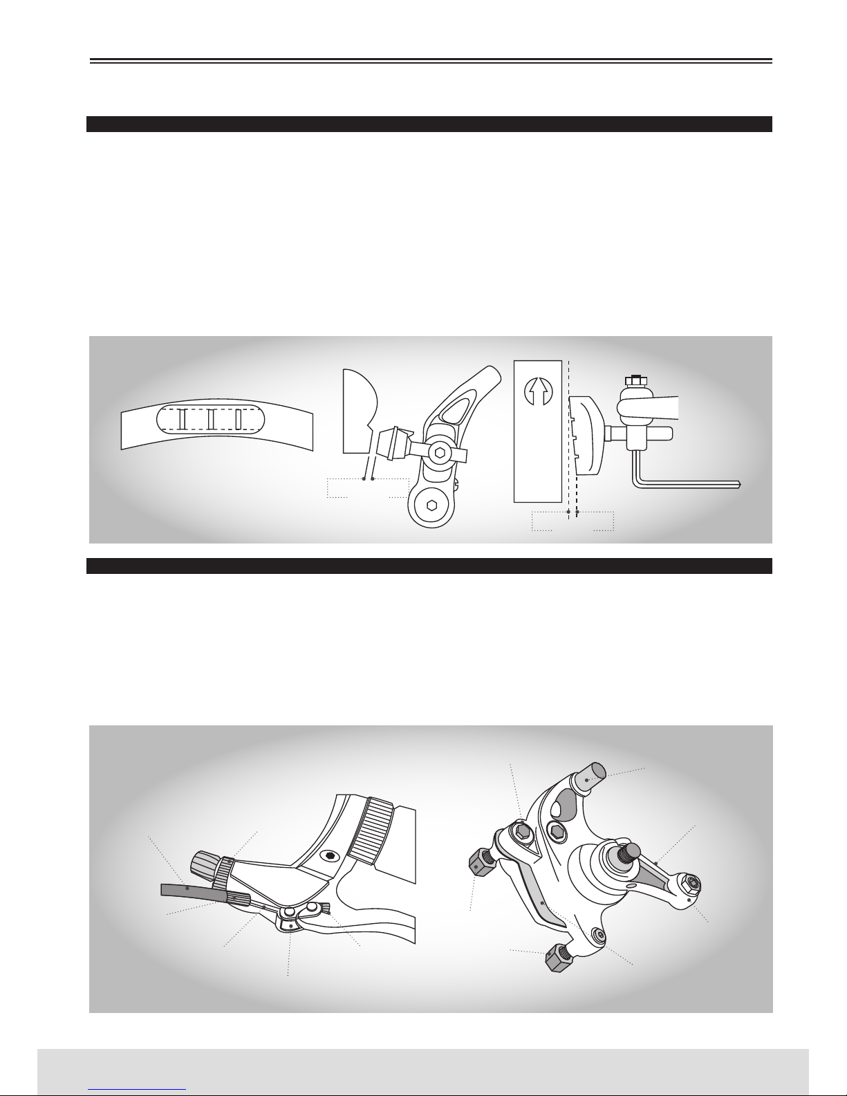
83
PORTUGUÊS
www.bergcycles.com
INSPECCIONE OS TRAVÕES
Pressione as manetes dos travões para se certificar que não ficam presas e que os calços dos travões
pressionam com a força suficiente os aros para parar a bicicleta. Os calços de travão devem ser ajustados de modo a ficarem 1 a 2mm de distância do aro quando os travões não são acionados. Os calços
de travão devem centrar-se no aro e .inclinar-se para a frente. de modo a que a parte traseira de cada
calço de travão esteja aproximadamente 0.5 a 1.0 mm mais longe do aro que a parte frontal do calço de
travão.Não ande de bicicleta até que os travões estejam a funcionar corretamente. Para os testar, trave
enquanto empurra a bicicleta para a frente para se certificar que estes param a bicicleta. Nunca ande
numa bicicleta que não funcione de maneira apropriada. Não bloqueie os travões. O uso repentino ou
excessivo do travão dianteiro pode lançar o ciclista para cima do guiador, causando lesões graves ou até
a morte. Ao travar, utilize sempre o travão traseiro primeiro, e depois o dianteiro.
TRAVÕES DE DISCO
Se a bicicleta estiver equipada com um travão de disco dianteiro, os componentes já deveriam estar colocados. No entanto, verifique todas as conexões antes de utilizar a bicicleta. Aperte bem os 6 parafusos
que sustêm o disco ao cubo da roda dianteira e os 2 parafusos que sustêm o mecanismo de travagem à
forqueta. Encaixe a roda dianteira entre as ponteiras da forqueta certificando-se de que o disco encaixa
no mecanismo de travagem entre as pastilhas de travão fechadas. Ligue a roda dianteira à bicicleta
apertando o mecanismo de abertura rápida e colocando a alavanca na posição de fechado. Consulte a
pág. 95 para obter mais informação sobre os mecanismos de abertura rápida.
MONTAGEM
0,5/1mm
1/2mm
CALÇO DE TRAVÃO ALINHADO COM A
SUPERFÍCIE DO ARO
O CALÇO E O ARO DEVEM ESTAR PARALELOS DIREÇÃO DA ROTAÇÃO DO ARO
ESPIRAL DO
CABO DE
TRAVÃO
TENSOR
RANHURA DE
INSERÇÃO DO
CABO
CABO DO
TRAVÃO
SUPORTE DA
EXTREMIDADE DO CABO
SELETOR DO TIPO DE
TRAVÃO
MANETE DO TRAVÃO
PARAFUSO DE
MONTAGEM DO
CALIBRADOR COM
ESPESSADORES
PASTILHAS DE TRAVÃO
CAVILHA DE FIXAÇÃO
DO CABO
BRAÇO ACIONADOR
BARRA DE ROTAÇÃO
CLIP C
PORCA DE
SEGURANÇA
Page 84
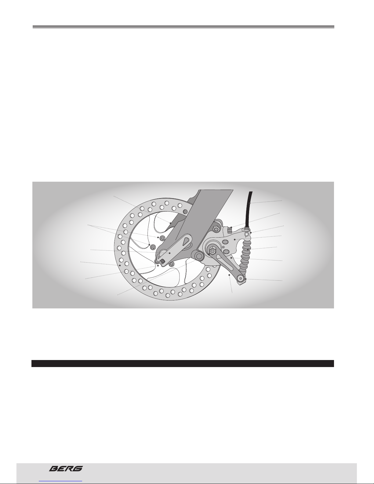
84
// MANUAL DO UTILIZADOR
PORTUGUÊS
Depois, ligue o cabo à manete do travão inserindo a extremidade do cabo no suporte depois de o tensor e
as ranhuras da porca de segurança estarem alinhadas com o suporte da extremidade do cabo. Depois de
o cabo estar ligado à manete, rode o tensor e a porca de segurança de maneira a que as ranhuras já não
fiquem alinhadas. Certifique-se de que a cobertura do cabo assenta apropriadamente na extremidade
do tensor e verifique se há danos.
Deslize o cabo de travão exposto através da barra de rotação localizada no corpo do calibrador e assente
a cobertura no mesmo terminal. Insira o cabo na mola e na bota da mola.
Seguidamente, deslize o cabo através do fixador do cabo e retire a tensão. Segure o cabo no seu lugar
apertando os parafusos que comprimem a montagem do fixador. Alguns travões de disco têm um dispositivo de centragem enquanto outros são mecanismos são de flutuação livre.
Se o corpo do calibrador estiver equipado com pernos de centragem, utilize a manete de travão depois
de o cabo estar conectado. Enquanto aperta a manete, aperte os pernos de centragem de forma segura.
Isto centrará o corpo do calibrador sobre o disco.
O DISCO AQUECE! Podem ocorrer lesões graves ao tocar no disco quente! Tenha cuidado com as pernas
e mãos.
Estes travões necessitam de assentar! Ande na bicicleta e utilize os travões com cuidado durante 20
quilómetros antes de os usar em descidas, travagens repentinas ou qualquer outra forma de travagem
complicada. Tenha em conta que o rendimento do sistema de travões modificará com o decorrer do tempo e uso. O travão a disco deve ser limpo com álcool de polimento antes da primeira saída. NUNCA utilize
óleo ou produtos semelhantes para limpar o sistema de travões de disco.
DESVIADOR
Apesar de os desviadores dianteiros e traseiros serem ajustados inicialmente na fábrica, deverá inspecioná-los e voltar a regulá-los antes de andar na bicicleta.
DESVIADOR TRASEIRO
Em primeiro lugar, coloque a mudança traseira no maior número indicado, desligue o cabo do perno de
fixação do cabo do desviador traseiro, e coloque a corrente no carreto mais pequeno. Aperte o parafuso
de limite alto de modo a que a roldana guia e o carreto mais pequeno fiquem alinhados de forma vertical.
Volte a conectar o cabo, retire qualquer tensão e volte a apertar o perno de fixação de forma segura.
Troque as velocidades, certificando-se de que cada comutação é feita com suavidade e sem vacilações.
Se for necessário, utilize o tensor para afinar cada troca de velocidade, rodando-o na direção para a qual
MONTAGEM
ALAVANCA DE
ABERTURA
RÁPIDA
PARAFUSOS DE
MONTAGEM DO
DISCO
COBERTURA
DO CABO DO
TRAVÃO
PERNO DE
CENTRAGEM
BARRA DE
ROTAÇÃO
CORPO DO
CALIBRADOR
BOTA DO CABO COM
MOLA NO INTERIOR
PERNO DE CENTRAGEM
(INTERIOR)
CAVILHA DE
FIXAÇÃO DO CABO
BRAÇO ACIONADOR
CUBO
PERNA DA FORQUETA
DISCO
PONTEIRAS DA
FORQUETA
PARAFUSOS DE MONTAGEM
DO CALIBRADOR COM
ESPESSADORES
Page 85
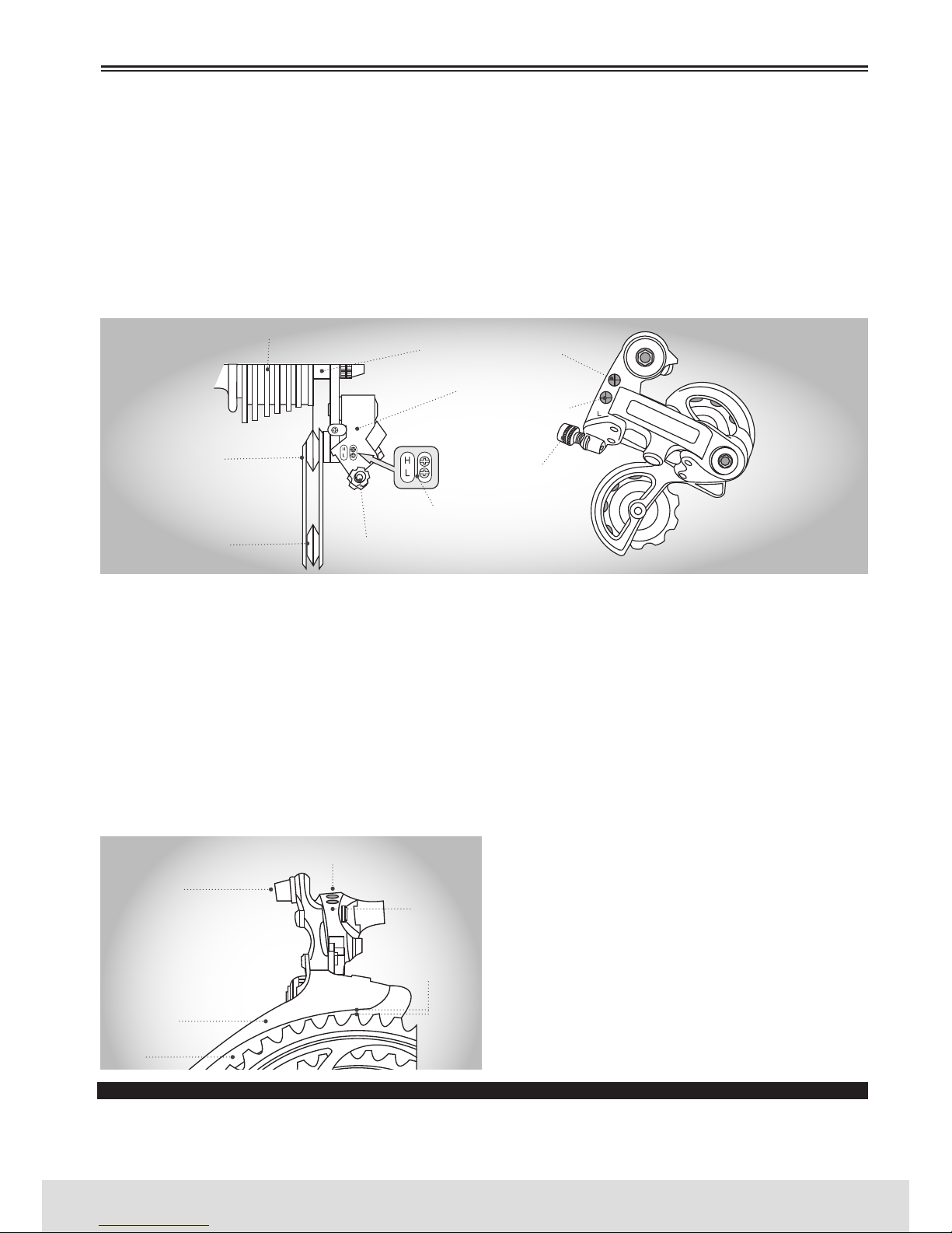
85
PORTUGUÊS
www.bergcycles.com
deseja que a corrente vá. Por exemplo, se rodar no sentido dos ponteiros do relógio, libertará a tensão
do cabo e a corrente sairá da roda, enquanto que rodando no sentido oposto aos ponteiros do relógio, a
tensão do cabo é apertada e a corrente mover-se-á para a roda. Coloque a mudança traseira na primeira velocidade e ponha a corrente no carreto maior. Ajuste o parafuso de limite baixo com incrementos
de voltas de um quarto até que a roldana guia e o carreto maior fiquem alinhados de forma vertical.
Novamente, troque cada velocidade várias vezes, verificando que cada mudança é feita suavemente.
Talvez seja necessário fazê-lo várias vezes até que o desviador traseiro e o cabo estejam ajustados
corretamente. Assegure-se de que todos os parafusos estão bem apertados e que a corrente não cai
para nenhum dos lados.
DESVIADOR DIANTEIRO
Coloque ambas as mudanças no número mais pequeno e ponha a corrente no carreto e prato correspondentes. Desligue o cabo do desviador dianteiro do perno de fixação do cabo. Verifique a posição do desviador dianteiro, que deverá estar paralelo ao prato externo e deixar livre o prato maior 1 a 3 mm, quando
totalmente engrenado. Com a corrente no prato mais pequeno à frente e carreto maior atrás, ajuste o
parafuso de limite Baixo para que a corrente fique centrada na guia do desviador dianteiro. Conecte novamente o cabo, tire toda a tensão e volte a apertar o perno de fixação de forma segura. Coloque a mudança
dianteira no prato maior. Se a corrente não se manter sobre o prato maior, rode o parafuso de limite Alto
em incrementos de voltas de 1/4 no sentido dos ponteiros do relógio até que a corrente não caia mais. Mude
todas as velocidades, utilizando o tensor para afinar cada comutação. O tensor do desviador dianteiro está
localizado no manípulo de mudanças dianteiro, no local de onde sai o cabo do manípulo de mudanças. Se
rodar no sentido dos ponteiros do relógio, libertará a tensão do cabo e a corrente aproximar-se-á do qua-
dro, enquanto que se rodar no sentido oposto aos
ponteiros do relógio, a tensão do cabo é apertada e a
corrente distancia-se do quadro. Nunca ande numa
bicicleta cujas mudanças de velocidade não estejam
a funcionar de maneira apropriada. Se não forem
realizados os ajustes apropriados, podem ocorrer
danos irreparáveis na bicicleta e/ou lesões corporais. Nunca troque de mudança quando pedalar para
trás, nem pedale para trás depois de ter movido o
manípulo de mudanças. Isto poderia travar a corrente e causar sérios danos na bicicleta e no ciclista.
DUPLA SUSPENSÃO
As bicicletas com suspensão dupla (DS) estão equipadas com uma forqueta dianteira para além de uma
MONTAGEM
RODA LIVRE
LADO EXTERNO DO
CARRETO SUPERIOR
PARAFUSO DE AJUSTE
DA ROLDANA
PARAFUSO DE AJUSTE
ALTO DO CARRETO
PARAFUSO DE AJUSTE
BAIXO DO CARRETO
TENSOR
VISTA LATERAL DO
DESVIADOR TRASEIRO
REGULADOR DO
CABO SIS
PARAFUSOS DE AJUSTE
ROLDANA GUIA
ROLDANA DE
TENSÃO
PARAFUSO DE AJUSTE
BAIXO
GUIA DO CABO
PARAFUSO DE
AJUSTE ALTO
ESPAÇO LIVRE DE
1-3mm DO
GUIA-CORRENTE
GUIA-CORRENTE
EXTERNA
PROTEÇÃO DA
CORRENTE INTERIOR
Page 86
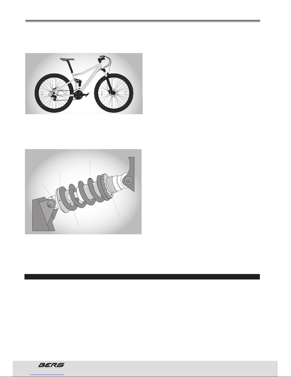
86
// MANUAL DO UTILIZADOR
PORTUGUÊS
suspensão traseira geralmente localizada debaixo do selim. O pistão trabalha em combinação com uma
mola para permitir que a bicicleta rode num ponto de pivô. Certifique-se de que todos os componentes
de fixação estão bem apertados e que não existe
nenhum movimento lateral no triângulo traseiro. O
grau de deslocamento da suspensão traseira pode
ser regulado rodando a placa de ajuste.Se rodar
no sentido dos ponteiros do relógio, a tensão da
mola aumentará e reduzir-se-á o deslocamento,
enquanto que se rodar no sentido oposto a tensão
da mola diminuirá e aumentará o deslocamento.
Existem muitos tipos de sistemas de suspensão
diferentes, demasiados para serem tratados de
forma individual neste manual.
Deve haver tensão suficiente na mola para suster a placa da mola no seu lugar. Se assim não for, é
possível que o mecanismo falhe. Se o sistema de suspensão não for mantido, inspecionado e ajustado
de maneira apropriada, poderá funcionar mal; isto poderá causar a perda de controlo e queda. Alterar
os ajustes da suspensão pode modificar as características de manejo e travagem da bicicleta. Nunca
altere os ajustes de suspensão a menos que tenha
um amplo conhecimento do sistema de suspensão,
instruções e recomendações do fabricante, e ins-
pecione sempre as alterações de comportamento
da bicicleta mediante um passeio experimental
cuidadoso, numa zona livre de perigos. Se a sua bi-
cicleta tiver equipamento de suspensão, e daí qui-
ser aumentar a velocidade, lembre-se que aumen-
tará também os riscos. Ao travar, a parte dianteira
de uma bicicleta com suspensão baixa-se. Poderá
perder o controlo e cair se não possuir a capacida-
de de lidar com este sistema. Aprenda a lidar com o
sistema de suspensão de maneira segura, antes de
fazer descidas ou andar a grande velocidade. Se a
sua bicicleta estiver equipada com um amortecedor a ar deve consultar o manual do fabricante (se este
existir). Para maior informação sobre o funcionamento e pressões a utilizar contacte o Departamento
Técnico da Berg Cycles. Nunca se esqueça das revisões periódicas do seu amortecedor. Não utilize a sua
bicicleta se a pressão do amortecedor não estiver correta. Poderá perder segurança na utilização e/ou
comprometer seriamente o funcionamento do mesmo. Para mais informação consultar pág. 103.
REVISÃO FINAL
Depois de realizar todos os ajustes, troque todas as mudanças várias vezes, em velocidades distintas.
Isto assegurará que todos os ajustes estão corretos e permiti-lo-á localizar as áreas problemáticas. Se
tiver algum problema, consulte a secção apropriada e realize os ajustes necessários. Verifique a pressão
dos pneus e encha cada câmara até ao valor recomendado (libras por polegada quadrada = psi), consoante o estabelecido no pneu. Verifique se o descanso funciona suavemente e o parafuso do mesmo
está bem apertado. Finalmente, examine a bicicleta. Certifique-se de que todos os acessórios estão
colocados e todas as alavancas de abertura rápida, porcas e parafusos estão bem apertados.
A correta manutenção da sua bicicleta garante-lhe muitos anos de passeios agradáveis.
Faça a manutenção da sua bicicleta com regularidade consultando as secções relevantes deste manual,
ou levando-a a uma oficina de bicicletas onde possa consultar técnicos profissionais.
MOLA
PLACA DA MOLA
PISTÃO
PLACA DE AJUSTE
PERNO DE
FIXAÇÃO
MONTAGEM
Page 87
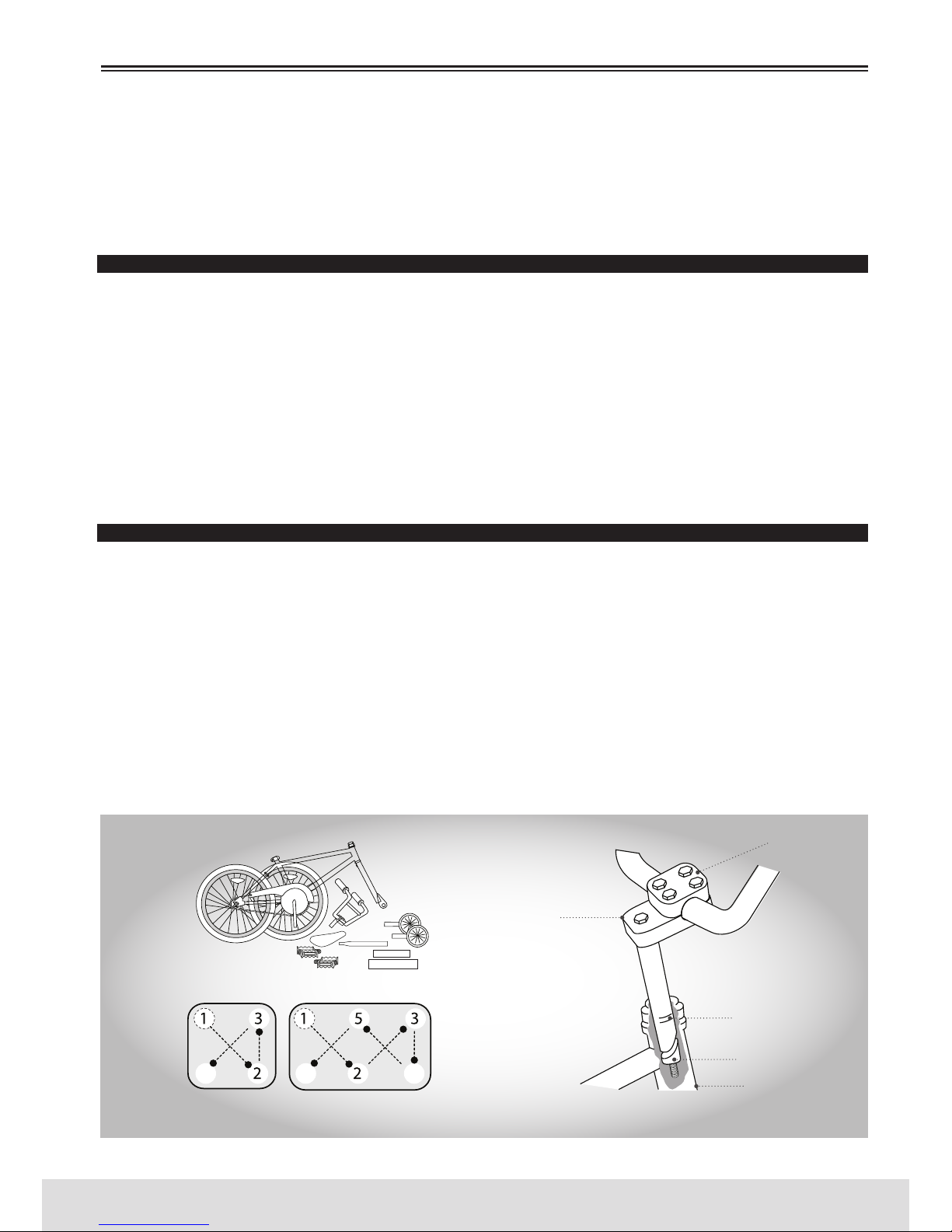
87
PORTUGUÊS
www.bergcycles.com
Use sempre capacete e obedeça a todas as regras de trânsito. Nunca encha um pneu para além da
pressão máxima, marcada na parte lateral do mesmo. Se exceder a pressão recomendada, o pneu pode
explodir e sair do aro, causando danos à bicicleta e lesões no ciclista e transeuntes.
Aperte as porcas do eixo da roda traseira ou o mecanismo de abertura rápida de forma segura. Se não o
fizer, a roda traseira poderá sair das ponteiras do quadro provocando danos e lesões graves.
CRIANÇA E BMX
Inclui bicicletas BMX de 12”, 14”, 16”, 20” e 24”. A montagem é similar para as bicicletas de homem
e mulher. Prólogo: A montagem de uma bicicleta constitui uma responsabilidade muito importante. A
montagem apropriada não só faz com que o ciclista desfrute mais da bicicleta, como também representa
uma importante medida de segurança. Como começar: Abra a caixa de cartão pela parte superior e tire
a bicicleta. Retire as fivelas e o invólucro de proteção da mesma. Inspecione a bicicleta e todos os acessórios e partes em busca de peças em falta. Recomenda-se a lubrificação das porcas e todas as partes
móveis da embalagem de partes antes da sua instalação. Não deite fora os materiais de embalamento
antes de finalizar a montagem, para se certificar de que não deitou fora partes necessárias de forma
acidental. Monte a bicicleta seguindo os passos respeitantes ao seu modelo. A bicicleta pode estar equipada com componentes de estilos diferentes aos ilustrados.
GUIADOR
Tire a capa protetora da cunha do avanço e desaperte o parafuso com uma chave Allen de 6mm. Alguns
modelos podem utilizar um parafuso hexagonal de 13mm, em vez de um parafuso de chave Allen. Coloque o avanço da direção no tubo de direção, observando a marca de inserção mínima no avanço da
direção e assegurando-se de que todos os cabos estão desimpedidos. Verifique se a forqueta e o guiador
estão virados para a frente e que estão corretamente alinhados com a roda dianteira. Aperte o parafuso
do avanço. Rode o guiador para a posição desejada. Aperte o parafuso da tampa do avanço 1 (ver esquema) com duas voltas, aperte o parafuso da tampa do avanço 2 e assim sucessivamente. Repita até que
o guiador fique preso ao avanço. Veja o esquema para o sistema de 4 ou 6 parafusos. Verifique também
se os parafusos de fixação do avanço estão presos de forma similar e segura.
O guiador deve inserir-se de maneira a que a marca de inserção mínima não se possa ver. Se o parafuso
do avanço ou a montagem do jogo de direção forem apertados excessivamente, poderão ocorrer danos
na bicicleta ou lesões no ciclista.
PLACA FRONTAL
DE DIREÇÃO DE 4
PARAFUSOS
PLACA FRONTAL DE DIREÇÃO
DE 6 PARAFUSOS
TUBO DE DIREÇÃO
CUNHA DO AVANÇO
MARCA DE
INSERÇÃO MÍNIMA
PARAFUSO DO AVANÇO
PARAFUSOS DA TAMPA DO
AVANÇO
MONTAGEM
Page 88
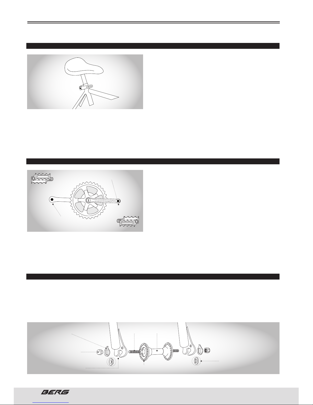
88
// MANUAL DO UTILIZADOR
PORTUGUÊS
MONTAGEM
SELIM
Desaperte a porca da abraçadeira do assento e coloque
3 ou 4 gotas de óleo no roscado do parafuso. Coloque
a extremidade mais pequena do espigão do selim na
abraçadeira do selim até que esta se detenha com o
parafuso virado para a parte posterior do tubo do assento. Enrosque a porca na abraçadeira sem apertar.
Insira a extremidade maior do espigão do selim no tubo
do selim do quadro da bicicleta, observando a marca de
inserção mínima no espigão do selim. Coloque a parte superior do selim de modo a este ficar paralelo
ao solo. As partes dentadas da abraçadeira do selim devem encaixar por completo com os do quadro do
selim; empurre a frente do selim para cima e para baixo para alinhar os dentes. Aperte bem a abraçadeira do selim. Aperte os parafusos na abraçadeira do espigão do selim firmemente. Coloque a bicicleta
ao contrário e apoie-a sobre o selim e o guiador. O espigão de selim deve ser inserido de maneira a que
a marca de inserção mínima fique invisível. Verificar de acordo com a pág. 72.
PEDAIS E PEDALEIRAS
Procure as letras “R” para a direita e “L” para a esquerda,
estampadas no eixo de cada pedal. Inicie a instalação
de cada pedal manualmente, para evitar que se danifi-
quem os roscados. Aperte com uma chave combinada de
15mm. Tenha em conta que o pedal direito é apertado à
pedaleira do lado da roda dentada com uma volta para
a direita (no sentido dos ponteiros do relógio). O pedal
esquerdo aperta-se à outra pedaleira com uma volta
para a esquerda (no sentido contrário aos ponteiros do
relógio). É muito importante verificar se o jogo de pedaleiras está corretamente ajustado e preso, antes
de andar na bicicleta. As pedaleiras novas podem desapertar com o uso inicial, consulte as pág. 101 à 102
para obter informação sobre o ajuste e manutenção apropriados do jogo de pedaleiras. Depois de os pedais estarem presos, verifique se a pedaleira gira suavemente e que não existe algum movimento lateral.
Se apertar o pedal errado à pedaleira, ocorrerão danos irreparáveis.
RODA DIANTEIRA
1. Certifique-se de que os travões estão suficientemente soltos para permitir que a roda passe através
das pastilhas de travão facilmente.
2. Coloque a roda dianteira entre as ponteiras da forqueta.
3. Instale as anilhas de retenção com o rebordo levantado apontando para a forqueta e insira-as no orifício pequeno da perna da forqueta. Algumas bicicletas podem ter anilhas de retenção progressiva em vez
INSIRA SOMENTE O PEDAL ESQUERDO
INSIRA SOMENTE O PEDAL DIREITO
IMPORTANTE!
IMPORTANTE!
EIXO CUBO
ANILHA DE RETENÇÃO
PROGRESSIVA
PORCAS CÓNICAS
PONTEIRAS DA FORQUETA
PORCA DO EIXO
ANILHA DE RETENÇÃO
Page 89
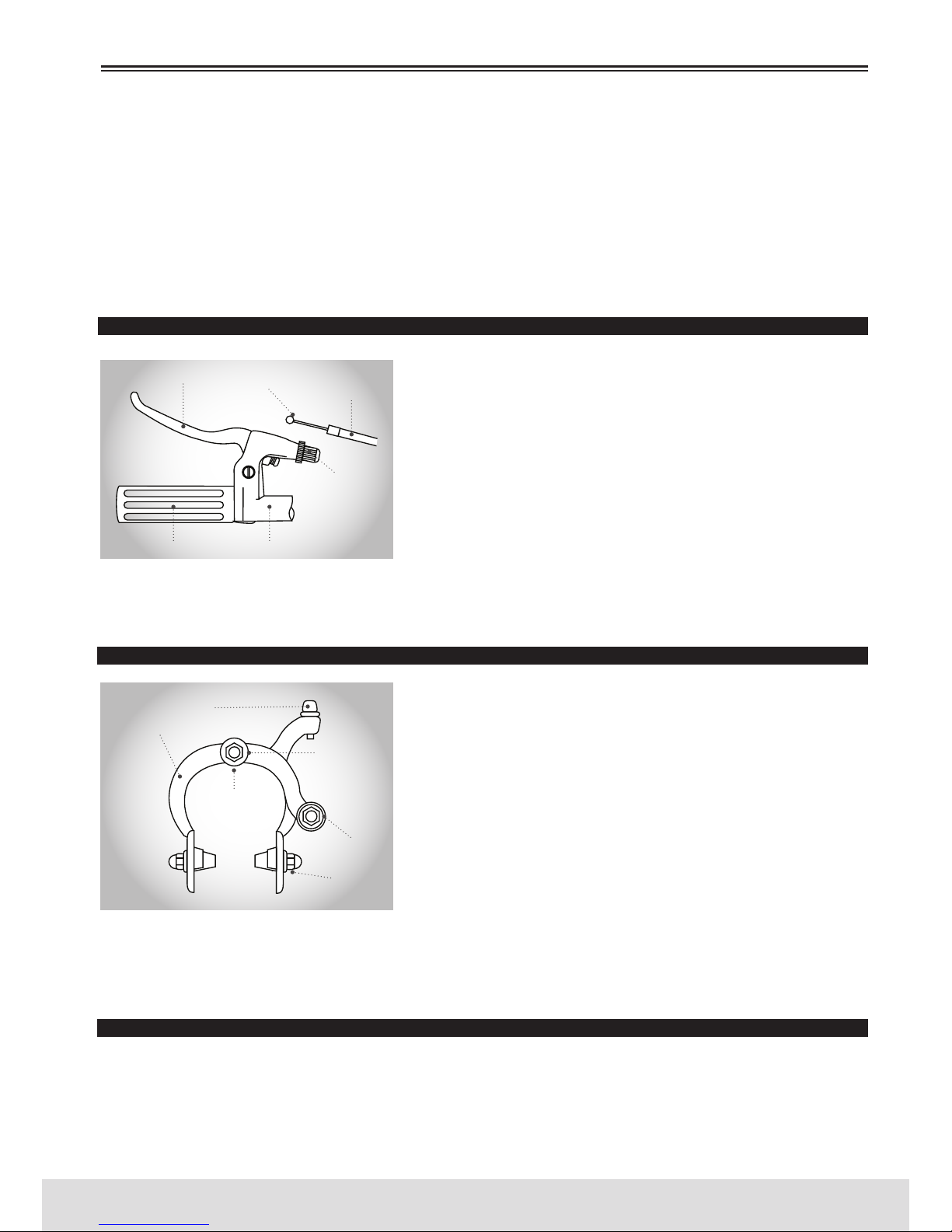
89
PORTUGUÊS
www.bergcycles.com
da anilha de retenção (desenhada no esquema com tracejado em redor). Se assim for, instale a anilha de
retenção progressiva com a parte levantada deslizando entre as pernas da forqueta.
4. Coloque a porca do eixo e aperte. Assegure-se de que a roda está centrada entre as pernas da forqueta.
5. Gire a roda para se certificar de que está centrada e não embate nas sapatas do travão.
Aperte os travões, se necessário.
6. Coloque a bicicleta em posição vertical utilizando o descanso para a suportar.
É muito importante inspecionar a ligação da roda dianteira à bicicleta. Se não estiver apertada de forma
adequada, é possível que a roda dianteira se solte.
TRAVÃO DIANTEIRO
Determine com que tipo de travões a sua bicicleta está equipada e consulte as respetivas instruções de montagem. Para obter mais informação sobre o ajuste e manutenção dos travões,
consulte as pág. 81 à 84. É necessária uma força maior para
ativar o travão traseiro devido ao comprimento do cabo. Recomenda-se montar o travão traseiro do lado da mão que tiver
mais força. É importante familiarizar-se com o uso dos travões
de mão. Quando ajustados de forma apropriada, estes travões
constituem um sistema de travagem eficiente. Mantenha sem-
pre o aro e as sapatas de travão limpas e sem cera, nem lubrificantes ou sujidade. Mantenha sempre os travões corretamente ajustados e em boas condições de
funcionamento. Abra a manete do travão e coloque a extremidade com terminal do cabo de travão curto
na manete, e depois feche-a. Segure a virola contra a manete, com o tambor de ajuste do cabo.
TRAVÃO LATERAL
Desaperte a porca de fixação do cabo e introduza o cabo de
travão através da mesma. Aperte a porca manualmente até co-
locar o cabo no seu lugar. Aperte os braços de travão ao mesmo
tempo, contra o aro da roda. Desaperte as porcas das sapatas
de travão e rode-as até que coincidam com o ângulo do aro.
Aperte as porcas firmemente. Puxe a extremidade do cabo do
travão com uma pinça, segure-o bem e aperte a porca de fixa-
ção do cabo de forma segura. Gire a roda; as sapatas de tra-
vão não devem tocar o aro em nenhum ponto e devem estar à
mesma distância do mesmo de ambos os lados. Certifique-se
de que todas as porcas e parafusos estão bem apertados. Teste
as manetes de travão entre 20 a 25 vezes para poder observar qualquer estiramento inicial do cabo.
Certifique-se que aperta bem a porca de fixação do travão por detrás da forqueta. Ao montar ou ajustar
os travões, assegure-se de que o fixador do cabo está teso. Se a porca não for apertada de forma segura, poderá ocorrer uma falha nos travões e, como consequência, lesões corporais.
TRAVÕES V-BRAKES
1. Se a sua bicicleta estiver equipada com travões tipo V, insira o corpo do travão no orifício central da mola,
no cubo de montagem do quadro e depois aperte o corpo do travão ao quadro com o parafuso de fixação.
2. Enquanto segura a sapata contra o aro, ajuste o grau de protuberância da sapata, intercalando a posição
das anilhas B (isto é, de 6mm ou 3mm) de maneira a que a dimensão A se mantenha a 39mm ou mais.
MONTAGEM
TAMBOR DE AJUSTE DO CABO
TAMBOR DE AJUSTE
DO CABO
GUIADORPUNHO
PORCA DE
FIXAÇÃO
DO CABO
SAPATA DO TRAVÃO
BRAÇO DO TRAVÃO
MANETE DE TRAVÃO
EXTREMIDADE
DO CABO
CABO DE TRAVÃO
PARTE
POSTERIOR
DA PORCA
DE FIXAÇÃO
PARAFUSO
CENTRAL
Page 90
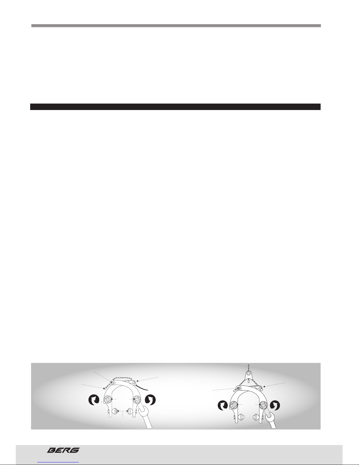
90
// MANUAL DO UTILIZADOR
PORTUGUÊS
3. Enquanto segura a sapata contra o aro, aperte a porca de fixação da mesma.
4. Passe o cabo interno através da guia do cabo interno. Coloque o cabo com um espaço livre de 1mm
entre cada calço de travão e o aro, aperte o parafuso de fixação do cabo.
5. Calibre com os parafusos de ajuste de tensão da mola.
6. Baixe a manete de travão aproximadamente 10 vezes à altura do punho, para verificar que tudo funciona corretamente e que o espaço livre da sapata é o correto, antes de utilizar os travões.
TRAVÕES U
Comece por ajustar os calços dos travões U com uma chave de 10mm. Certifique-se de que o calço toca no aro
e não no pneu. O ideal é que a frente do calço toque no aro aproximadamente 1 mm antes do calço traseiro.
TRAVÃO U DIANTEIRO
Deslize o cabo e a cobertura do travão através do tambor do travão e do parafuso de fixação do cabo. Estabeleça um espaço livre para o cabo de 1mm entre os calços de travão e o aro. Aperte o parafuso de fixação
do cabo. Para seguir as instruções ilustradas, olhe a bicicleta de frente. Para ajustar os travões utilize uma
chave combinada de 13mm e uma chave Allen de 5mm. Desaperte o parafuso allen de 5mm. Para o lado dos
carretos (esquerdo) da bicicleta, rode a porca de tensão da mola com uma chave combinada de 13mm no
sentido contrário ao dos ponteiros do relógio, para aumentar a tensão na mola. Para o lado onde não se encontram carretos (lado direito), rode a porca de tensão da mola com uma chave combinada no sentido dos
ponteiros do relógio, para aumentar a tensão na mola. Quando obtiver a tensão desejada, segure a porca
de tensão com a chave combinada de 13mm e aperte o parafuso allen de 5mm. A tensão de cada lado deve
ser a mesma de modo a que os braços do travão se movam à mesma distância quando o travão é ativado.
U REAR BRAKE
Opção 1: Depois, aperte o transportador do cabo ao cabo do travão aproximadamente a 20mm dos bra-
ços de travão, quando estes estão apertados contra o aro. Aperte o cabo de travão ao transportador.
Encaixe o terminal do cabo na ranhura do travão, puxe o cabo excedente através do fixador do cabo e
aperte o fixador do cabo. Continue com a parte “Para as duas opções”, mais abaixo.
Opção 2: Coloque a cobertura do travão nos bloqueadores da cobertura do quadro. Puxe o cabo do travão
de modo a que este fique teso e passe-o pelo parafuso de fixação do cabo oposto. Aperte o cabo. Repita
o processo para o outro lado. Continue com a parte .Para as duas opções., em seguida. Para as duas
opções: Para os ajustes do travão, utilize uma chave combinada de 13mm e uma chave allen de 5mm
e desaperte o parafuso allen de 5mm. Para o lado dos carretos (direito) da bicicleta, rode a porca de
tensão da mola com uma chave combinada de 13mm no sentido contrário aos ponteiros do relógio, para
aumentar a tensão da mola. Para o lado onde não se encontram carretos (esquerdo), rode a porca de
tensão da mola com uma chave combinada no sentido dos ponteiros do relógio, para aumentar a tensão
da mola. Quando obtiver a tensão desejada, segure a porca de tensão com a chave de 13mm e aperte o
parafuso allen de 5mm. A tensão de cada lado deve ser a mesma de maneira a que os braços de travão
se movam à mesma distância quando o travão é ativado.
TENHA EM CONTA que alguns quadros BMX têm travões U voltados e montados debaixo dos tirantes.
A direção para tensionar as molas estará orientada da mesma forma que ilustrada.
MONTAGEM
CABO DO TRAVÃO
CABO DO TRAVÃOTRAVÃO U TRASEIRO
OPÇÃO 1
TRAVÃO U DIANTEIRO
TAMBOR DO TRAVÃO
ENCAIXE DO
TERMINAL DO CABO
PASTILHAS DE
TRAVÃO
PARAFUSO
ALLEN
5mm
PARAFUSO
ALLEN
5mm
PARAFUSO DE
FIXAÇÃO DO CABO
FIXADOR DO CABO
CABO DE TRAVÃO
BIFURCADO
TRANSPORTADOR
DO CABO
TERMINAL DA
EXTREMIDADE DO CABO
PARA TENSIONAR
A MOLA
PARA TENSIONAR
A MOLA
PARA TENSIONAR
A MOLA
PARA TENSIONAR
A MOLA
PORCA DE TENSÃO
DA MOLA
PORCA DE TENSÃO
DA MOLA
PORCA DE TENSÃO
DA MOLA
PORCA DE TENSÃO
DA MOLA
Page 91
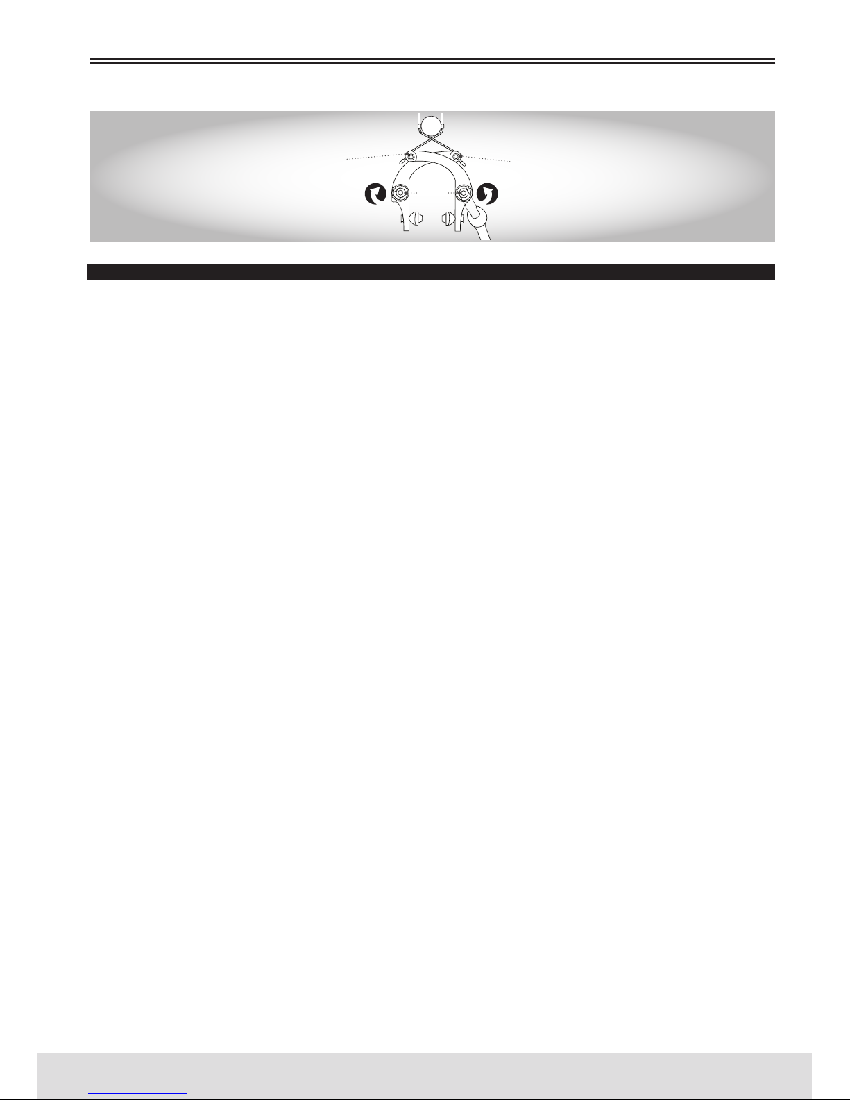
91
PORTUGUÊS
www.bergcycles.com
INSPECIONE OS TRAVÕES
Pressione as manetes dos travões para se certificar de que não bloqueiam e que os calços de travão
pressionam, com força suficiente, os aros para deter a bicicleta. Os calços de travão devem ajustar-se de
maneira a que fiquem a 1 ou 2mm de distância do aro quando os travões não são acionados. Os calços de
travão devem centrar-se no aro e a parte traseira de cada calço de travão deve estar aproximadamente
0.5 a 1.0mm mais afastadas do aro que na parte frontal. Não ande de bicicleta até que os travões funcionem adequadamente. Para os testar, aplique os travões enquanto empurra a bicicleta para a frente,
certificando-se de que estes a detêm.
ROTORES
Algumas bicicletas BMX de estilo livre vêm equipadas com um sistema de desenredar que o guiador gire
360 graus sem bloquear os cabos. É muito importante que este sistema seja ajustado corretamente. A
instalação só deve ser realizada por um mecânico de bicicletas qualificado, e com as ferramentas corretas.
CABO SUPERIOR
1. Primeiro ligue a extremidade do tambor do cabo superior à manete do travão traseiro.
Certifique-se de que o revestimento do cabo longo está por cima do revestimento do cabo curto, caso
contrário, o cabo superior ficará torcido nele.
2. Passe o cabo superior através do guiador (debaixo da barra) com o revestimento do cabo curto do
mesmo lado que a manete de travão traseiro.
3. Ligue o cabo superior à placa superior passando as porcas cegas do cabo superior através dos orifícios
roscados da placa superior e ligando-os ao rolamento.
4. Enrosque os tambores de estiramento na placa superior. Não aperte as porcas de segurança neste
momento.
CABO INFERIOR
1. Deslize a espiral do cabo através da guia do cabo no quadro.
2. Ligue o cabo inferior à placa inferior passando as porcas cegas do cabo inferior através dos orifícios
roscados na placa inferior e ligando-os ao rolamento.
3. Enrosque os tambores de estiramento na placa inferior. Não aperte as porcas de segurança neste momento.
4. Ligue o cabo inferior ao travão traseiro. Não aperte o travão traseiro neste momento.
Certifique-se de que todas as extremidades do tubo de espiral de cabo nos cabos superior e inferior
estão assentes corretamente, e que a tensão da mola do travão traseiro está a puxar o rolamento para
baixo.
AJUSTES
1. Enrosque os reguladores de cabo na manete de travão traseiro, e o divisor do cabo superior por completo.
2. Enrosque os tambores de estiramento na placa superior para dentro (ou para fora) para ajustar o rolamento a fim de obter o máximo deslocamento. O rolamento deve estar o mais baixo possível sem estar
apoiado sobre a placa inferior ou os tambores de esticamento aparafusados na placa inferior.
3. Use os tambores de estiramento aparafusados na placa superior para colocar o rolamento numa posição paralela à placa superior. Use uma chave de 10mm para apertar a porca de segurança no tambor de
estiramento esquerdo do cabo superior. Não aperte o tambor de estiramento direito.
MONTAGEM
COBERTURA DO TRAVÃO
TRAVÃO U TRASEIRO
OPÇÃO 2
CABO DO TRAVÃO
PARAFUSO
ALLEN
5mm
FIXADOR DO CABO
CABO DO TRAVÃO
BLOQUEADORES DA COBERTURA
DO QUADRO
PARA TENSIONAR
A MOLA
PARA TENSIONAR
A MOLA
PORCA DE TENSÃO
DA MOLA
PORCA DE TENSÃO
DA MOLA
FIXADOR DO CABO
Page 92
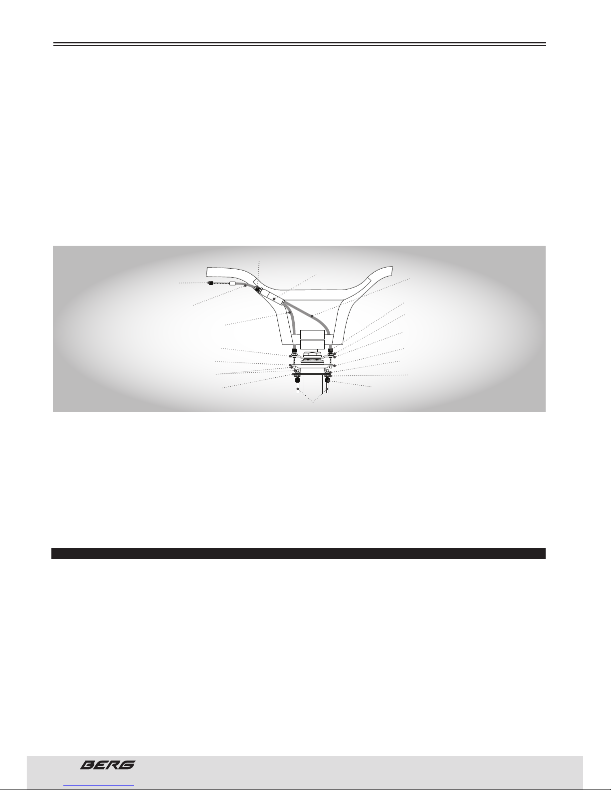
92
// MANUAL DO UTILIZADOR
PORTUGUÊS
4. Aparafuse o tambor de estiramento do cabo inferior na (ou fora da) placa inferior até que esteja o mais
perto possível do rolamento, sem o tocar.
5. Aparafuse o regulador do cabo no divisor do cabo superior até eliminar toda a tensão do cabo superior.
Depois, enrosque o regulador de cabo mais uma vez, para levantar o rolamento 1mm mais em direção
oposta ais tambores de estiramento do cabo inferior.
Não enrosque o regulador de cabo no divisor do cabo superior mais de 8mm. Utilize o regulador de cabo
na manete de travão traseiro se precisar de um maior ajuste.
6. Verifique o ruído do rolamento colocando o guiador na posição normal de direção, e de seguida girando-o rapidamente para trás e para a frente. Siga os passos detalhados que se seguem, para eliminar o
ruído do rolamento.
Nuca se deve permitir que o rolamento descanse sobre a placa inferior ou dos tambores de estiramento
do cabo inferior.
a) Enrosque os tambores de estiramento do cabo inferior para fora (ou para dentro) da placa inferior até
eliminar todo o ruído produzido pelo rolamento.
b) Aperte a porca de segurança do tambor de estiramento direito no cabo inferior.
c) Rode o guiador 180 graus e verifique novamente o ruído do rolamento. Se o rolamento produz algum
ruído, use os tambores de estiramento “soltos” sobre os cabos superior e inferior para o eliminar.
d) Repita os passos (6a) e (6c) até que o guiador possa rodar 360 graus sem que o rolamento produza algum ruído.
e) Acabe de apertar os travões traseiros.
Se os ajustes não forem feitos corretamente, poder-se-á perder capacidade de travagem e originar
lesões corporais.
INSTRUÇÕES PARA A MONTAGEM DO APOIA-PÉS
SEM ROSCA
Primeiro tire a porca do eixo da roda. Encontrará uma anilha de retenção ou uma anilha de retenção
progressiva. Coloque esta anilha entre o apoia-pés e o quadro da bicicleta.
Deslize o apoia-pés no eixo, seguido da anilha plana e por último a porca do eixo. Aperte a porca do eixo
no sentido dos ponteiros do relógio, até que o apoia-pés esteja perfeitamente apertado contra o quadro
ou forqueta. Repita para todos os apoia-pés restantes.
COM ROSCA
Este tipo de apoia-pés enrosca-se para se ajustar ao eixo. Certifique-se de que a porca do eixo está
apertada com uma chave de 15mm. Insira uma chave através dos orifícios de montagem do apoia-pés
e aperte-o ao eixo girando no sentido dos ponteiros do relógio. Aperte contra o quadro ou forqueta para
obter um encaixe perfeito. Repita para todos os apoia-pés restantes.
MONTAGEM
EXTREMIDADE
DO TAMBOR
REVESTIMENTO DO CABO INDIVIDUAL
CABO SUPERIOR
(REVESTIMENTO LONGO)
CABO SUPERIOR
(REVESTIMENTO CURTO)
REGULADOR DO CABO
DIVISOR DO CABO
PLACA SUPERIOR
ROLAMENTO
PORCAS CEGAS
PLACA INFERIOR
CABO INFERIOR
TAMBOR DE ESTIRAMENTO
TAMBOR DE ESTIRAMENTO
PORCA DE SEGURANÇA
MÍNIMO 1mm (1/32.)
ANILHA COM CHAVETA
PORCA DE SEGURANÇA
AJUSTE PARA DESLOCAMENTO
MÁXIMO
Page 93
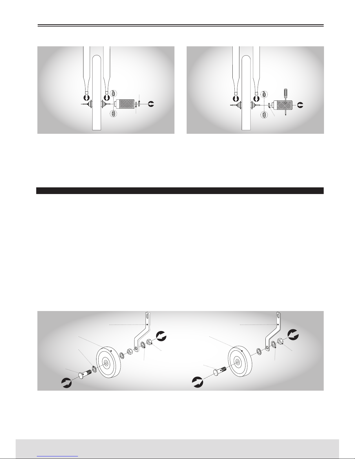
93
PORTUGUÊS
www.bergcycles.com
MONTAGEM
SEM ROSCA COM ROSCA
PONTEIRAS RETENÇÃO
DIANTEIRA/TRASEIRA
PONTEIRAS RETENÇÃO
DIANTEIRA/TRASEIRA
ANILHA DE
RETENÇÃO
ANILHA DE
RETENÇÃO
ANILHA DE RETENÇÃO
PROGRESSIVA
ANILHA DE RETENÇÃO
PROGRESSIVA
PORCA DO EIXO
ANILHA
PORCA DO EIXO
CUBO DIANTEIRO/
TRASEIRO
CUBO DIANTEIRO/
TRASEIRO
Nem todos os eixos podem levar Pousa-Pés. Consulte o seu distribuidor local se quiser esclarecer alguma dúvida. Algumas bicicletas BMX vêm com dois ou quatro apoia-pés. Se a sua é uma bicicleta Salto
em Terra (Dirt Jump) poderá receber apenas dois Pousa-Pés. Estes estão desenhados para um lado
apenas. As bicicletas de estilo livre (Freestyle) poderão vir com quatro Pousa-Pés, dois para cada roda.
As bicicletas Dirt Jump por norma não vêm com Pousa-Pés.
RODAS AUXILIARES PARA APRENDIZAGEM
Existem duas opções para colocar as rodas auxiliares para aprendizagem no suporte da roda. Determine
que opção é utilizada na sua bicicleta e siga as respetivas instruções para essa opção.
OPÇÃO 1 - Primeiro aperte as rodas auxiliares ao suporte da roda. Coloque uma anilha no parafuso de
ressalto. De seguida, insira o parafuso de ressalto através da roda. Coloque outra anilha plana e enrosque
uma porca hexagonal no parafuso de ressalto. Insira o parafuso de ressalto através do suporte da roda
e coloque uma anilha no parafuso de ressalto. Aperte a roda auxiliar no lugar enroscando outra porca
hexagonal no parafuso de ressalto. Repita o procedimento para a outra roda auxiliar.
OPÇÃO 2 - Primeiro aperte as rodas auxiliares ao suporte da roda. Insira o parafuso de ressalto através
da roda. De seguida, coloque uma anilha plana. Insira o parafuso de ressalto através do suporte da roda
e coloque uma anilha no parafuso de ressalto. Aperte a roda auxiliar no lugar enroscando outra porca
hexagonal no parafuso de ressalto. Repita o procedimento para a outra roda.
É muito importante inspecionar a ligação da roda auxiliar à bicicleta. Se não se apertar corretamente, a
roda auxiliar poderá soltar-se. Entre em contacto com o distribuidor local se tiver alguma dúvida.
COLOCAR O SUPORTE DA RODA AUXILIAR PARA APRENDIZAGEM NA BICICLETA
Existem dois suportes diferentes que se utilizam para colocar as rodas auxiliares na bicicleta: O suporte
com forma de C e o suporte plano. Determine que suporte a sua bicicleta inclui e siga as respetivas instruções para esse suporte em particular.
OPÇÃO 1 OPÇÃO 2
SUPORTE DA RODA SUPORTE DA RODA
RODA AUXILIAR DE APRENDIZAGEM RODA AUXILIAR DE APRENDIZAGEM
ANILHA
PARAFUSO DE
RESSALTO
PARAFUSO DE
RESSALTO
ANILHA ANILHA
PORCA
HEXAGONAL
PORCA
HEXAGONAL
Page 94
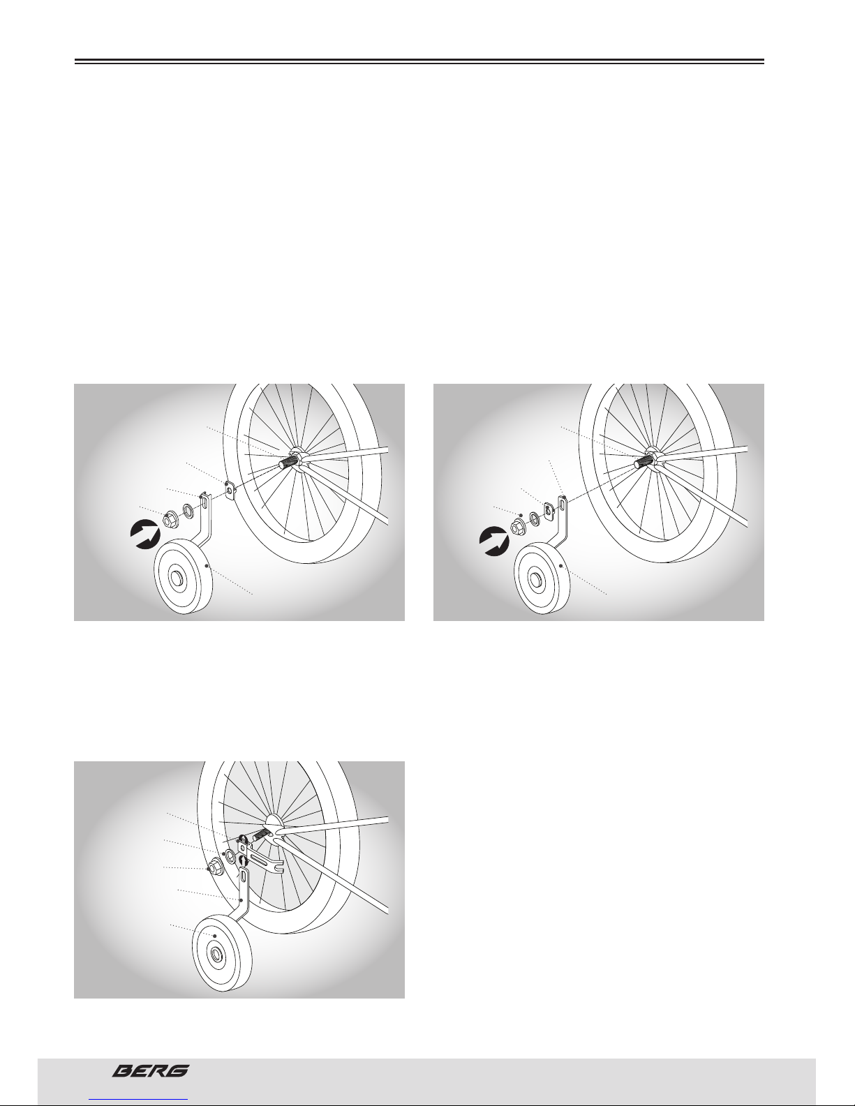
94
// MANUAL DO UTILIZADOR
PORTUGUÊS
MONTAGEM
SUPORTE COM FORMA DE C
Tire a porca e a anilha do eixo da roda traseira. Coloque a anilha do estabilizador do suporte no eixo e
alinhe-a de maneira a que o orifício da anilha encaixe na ranhura do quadro traseiro. De seguida, coloque
o suporte com forma de C no eixo e volte a colocar a anilha e a porca do eixo. Aperte a porca do eixo
firmemente, certificando-se de que o suporte da roda permanece em posição vertical apropriada. O orifício alargado no suporte da roda permite ajustar a altura da roda auxiliar, para a colocar na forma mais
adequada.
SUPORTE PLANO
Tire a porca e a anilha do eixo da roda traseira. Coloque o suporte plano da roda no eixo. De seguida, coloque
a anilha do estabilizador do suporte no eixo e alinhe-a de maneira a que o orifício da anilha encaixe na
ranhura do quadro traseiro. Volte a colocar a anilha e a porca do eixo. Aperte a porca do eixo firmemente,
certificando-se de que o suporte da roda permanece em posição vertical apropriada. O orifício alargado no
suporte da roda permite ajustar a altura da roda auxiliar, para a colocar na forma mais adequada.
SUPORTE DA RODA ESTABILIZADORA AUXILIAR PARA APRENDIZAGEM
A sua bicicleta pode ter incluído um suporte de estabilizador para apertar a roda auxiliar à bicicleta.
Retire a porca e a anilha do eixo da roda traseira. Alinhe o suporte estabilizador com o suporte da roda.
Alinhe o suporte da roda e o suporte do estabilizador no eixo da roda. Volte a colocar a porca e a anilha
do eixo; aperte bem. O orifício alargado no suporte permite subir e baixar a roda auxiliar, para obter a
altura adequada.
Nem todas as bicicletas permitem a colocação de
rodas auxiliares. Se a sua bicicleta não veio equipada com rodas auxiliares, contacte o seu revendedor
local, para que o ajudem a verificar se pode colocar
rodas auxiliares de pós-venda, na sua bicicleta.
É muito importante verificar a ligação da roda auxiliar
à bicicleta. Se não se apertar de forma adequada, a
roda auxiliar poderá soltar-se. Contacte o distribuidor local se quiser esclarecer alguma questão.
EIXO INTERNO
PORCA DO EIXO INTERNO
NÃO TIRAR
EIXO INTERNO
PORCA DO EIXO INTERNO
NÃO TIRAR
ANILHA DO ESTABILIZADOR
DO SUPORTE
SUPORTE DE RODA
PLANO
SUPORTE DA RODA
COM FORMA DE C
ANILHA DO ESTABILIZADOR
DO SUPORTE
PORCA DO
EIXO
PORCA DO
EIXO
RODA AUXILIAR PARA
APRENDIZAGEM
RODA AUXILIAR PARA
APRENDIZAGEM
OPÇÃO COM FORMA C OPÇÃO PLANO
ANILHA
PORCA DO EIXO
SUPORTE DO
ESTABILIZADOR
SUPORTE DA RODA
RODA AUXILIAR PARA
APRENDIZAGEM
Page 95
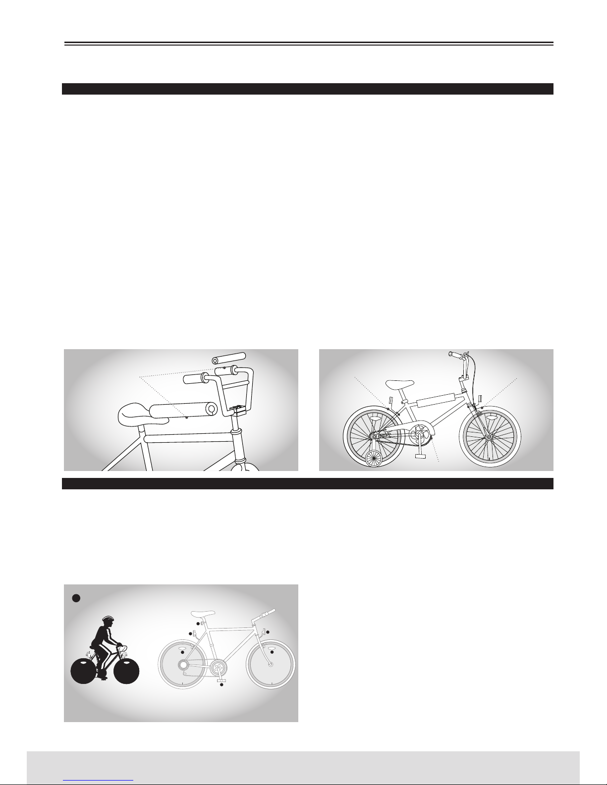
95
PORTUGUÊS
www.bergcycles.com
REVISÃO FINAL
Instale todas as partes adicionais fornecidas com a sua bicicleta. É possível que a sua bicicleta esteja
equipada com componentes de estilos diferentes aos ilustrados.
REFLECTORES - Aperte o refletor branco ao suporte dianteiro e o refletor vermelho ao suporte traseiro,
com uma chave de 8mm ou uma chave Philips. Aperte os suportes à bicicleta com os parafusos e porcas
fornecidas. Em alguns modelos, o suporte do refletor dianteiro deve montar-se no parafuso de montagem
do travão dianteiro, que se coloca por entre a forqueta. É muito importante certificar-se de que todas as
ligações estão apertadas de forma segura e que os refletores estão orientados de forma adequada.
PROTECTORES - Se a sua bicicleta está equipada com protetores, envolva o protetor com espuma no seu
interior, em redor da barra da bicicleta apropriada. Coloque a cobertura externa sobre o protetor interno
e una as fitas de velcro, pressionando-as firmemente. Rode o protetor de maneira a que as tiras de
velcro fiquem voltadas para baixo.
PROTEGE-CORRENTE - Se ainda não estiver colocado, coloque o protege-corrente no quadro da bicicleta utilizando
as braçadeiras fornecidas. Coloque-o no seu lugar tendo em conta que este não deverá impedir ou tocar na corrente.
PRESSÃO DOS PNEU - Verifique a pressão dos pneus; encha-os até ao nível recomendado na parte lateral dos pneus.
CAVILHAS – Existem demasiados tipos diferentes de cavilhas, pelo que é impossível mencioná-los indivi-
dualmente neste manual. Consulte o seu distribuidor para obter informação específica relacionada com
a instalação de cavilhas. Antes de utilizar a sua bicicleta, certifique-se de que todos os parafusos, porcas
e acessórios foram seguramente apertados.
ALAVANCAS DE ABERTURA RÁPIDA
É importante fazer a revisão das alavancas de abertura rápida antes de cada utilização de modo a garantir que
todas as conexões estão feitas de forma apropriada e segura. Periodicamente, desmonte o mecanismo e verifique
se não há desgastes ou partes danificadas e, se for necessário, substitua. Quando instalar novamente, é muito
importante verificar se todas as conexões foram feitas de forma apropriada. Consulte as pág. 80 à 81 para obter
informação sobre as instruções de montagem apropriadas.
REFLECTORES
A sua bicicleta tem com um refletor dianteiro (branco), um
traseiro (vermelho), dois nas rodas (brancos) e dois nos
pedais (laranjas). Estes são requisitos legais e de segurança importantes, e devem estar colocados de maneira
segura, limpos e em boas condições a todo o momento.
Inspecione todos os refletores, suportes e parafusos e
porcas de montagem em busca de sinais de desgaste ou
danos, de forma periódica. Substitua de imediato se encontrar partes danificadas (Consulte a pág. 75 para obter
mais informação).
MONTAGEM
PROTECTORES
REFLETOR TRASEIRO
(VERMELHO)
REFLETOR DIANTEIRO
(BRANCO)
PROTEGE-CORRENTE
REFLECTORES
COLOQUE UMA LUZ
NA SUA BICICLETA SE
ANDAR DE NOITE
USE ROUPA REFLETORA
QUANDO ANDAR DE BICICLETA
Page 96
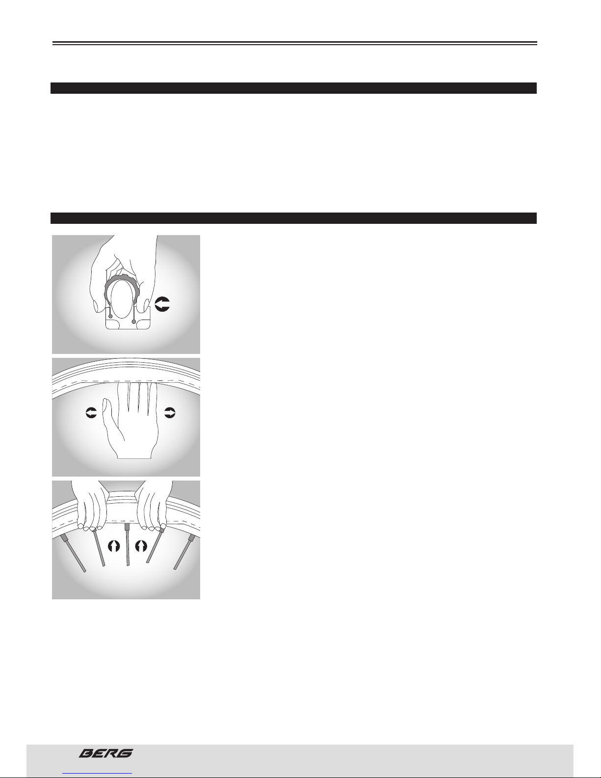
96
// MANUAL DO UTILIZADOR
PORTUGUÊS
PRESSÃO RECOMENDADA PARA OS PNEUS
A pressão recomendada e presente na parte lateral dos pneus deve coincidir com o quadro seguinte.
Utilize-o como um guia geral.
BMX - 35-50 psi / 2-3.45 Bar
BICICLETA DE MONTANHA - 40-65 psi / 2.6-4.5 Bar
BICICLETA DE PASSEIO - 70-90 psi / 4.8-6.2 Bar
BICICLETA DE ESTRADA - 110-125 psi / 7.6-8.5 Bar
HÍBRIDA/BICICLETA DE CROSS - 60-100 psi / 4.1-6.9 Bar
COMO REPARAR UM PNEU FURADO
Se precisar de reparar um pneu, proceda da seguinte forma:
1. Tire a roda da bicicleta.
2. Esvazie o pneu completamente, através da válvula. Solte o rebordo
do pneu, empurrando-o para dentro do aro.
3. Pressione um lado do rebordo do pneu para cima, sobre a borda do aro.
Não use uma chave, mas sim alavancas para pneus, caso contrário poderá danificar o aro.
4. Retire a câmara-de-ar, deixando o pneu sobre o aro.
5. Localize as fugas de ar e tape-as utilizando o kit de reparação de câmaras, seguindo cuidadosamente as instruções, ou substitua a câmara.
Certifique-se de que o tamanho da câmara de substituição coincide
com o tamanho indicado na parte lateral do pneu e que a válvula é do
tipo adequado à sua bicicleta.
6. Compare a posição da fuga na câmara com o pneu, para localizar a
possível causa e marcar a localização no pneu.
7. Tire completamente o pneu e inspecione procurando pregos, vidros,
etc. E se os encontrar retire-os. Inspecione também o interior do aro
para se certificar de que não há raios sobressaídos, ferrugem ou outras
causas possíveis. Substitua a cinta do aro que cobre as extremidades
dos raios, se estiver danificada.
8. Volte a montar um lado do pneu no aro.
9. Com uma bomba manual, encha a câmara somente o suficiente para
lhe dar forma.
10. Coloque a válvula através do orifício no aro e coloque a câmara no
pneu. NOTA: Não permita que esta se torça.
11. Unicamente com as mãos, volte a montar o outro lado do pneu empurrando o rebordo para o centro do aro. Comece com ambos os lados
da válvula e trabalhe em redor do aro.
12. Antes de o pneu estar completamente montado, empurre a válvula para cima no aro, para se certificar de que o pneu pode assentar diretamente na sua posição.
13. Coloque o resto do pneu, fazendo rodar a parte final, mais difícil, com os polegares. NOTA: Evite o
uso das alavancas para os pneus porque estas podem furar facilmente a câmara ou danificar o pneu.
Empurre o pneu para dentro do aro.
14. Verifique se a câmara não está presa entre o aro e o rebordo do pneu em algum ponto.
15. Com uma bomba manual, encha a câmara até que o pneu comece a ganhar forma, e verifique se o
rebordo do pneu está assente de uma forma regular em todo o aro.
Quando estiver corretamente assente, encha completamente o pneu até à pressão indicada na parte
MANUTENÇÃO
PUSH THE EDGE OF THE TIRE TOWARD
THE CENTRE OF THE RIM
REMOVE THE EDGE OF THE TIRE OF THE RIM
PUSH THE TIRE INTO THE RIM
Page 97
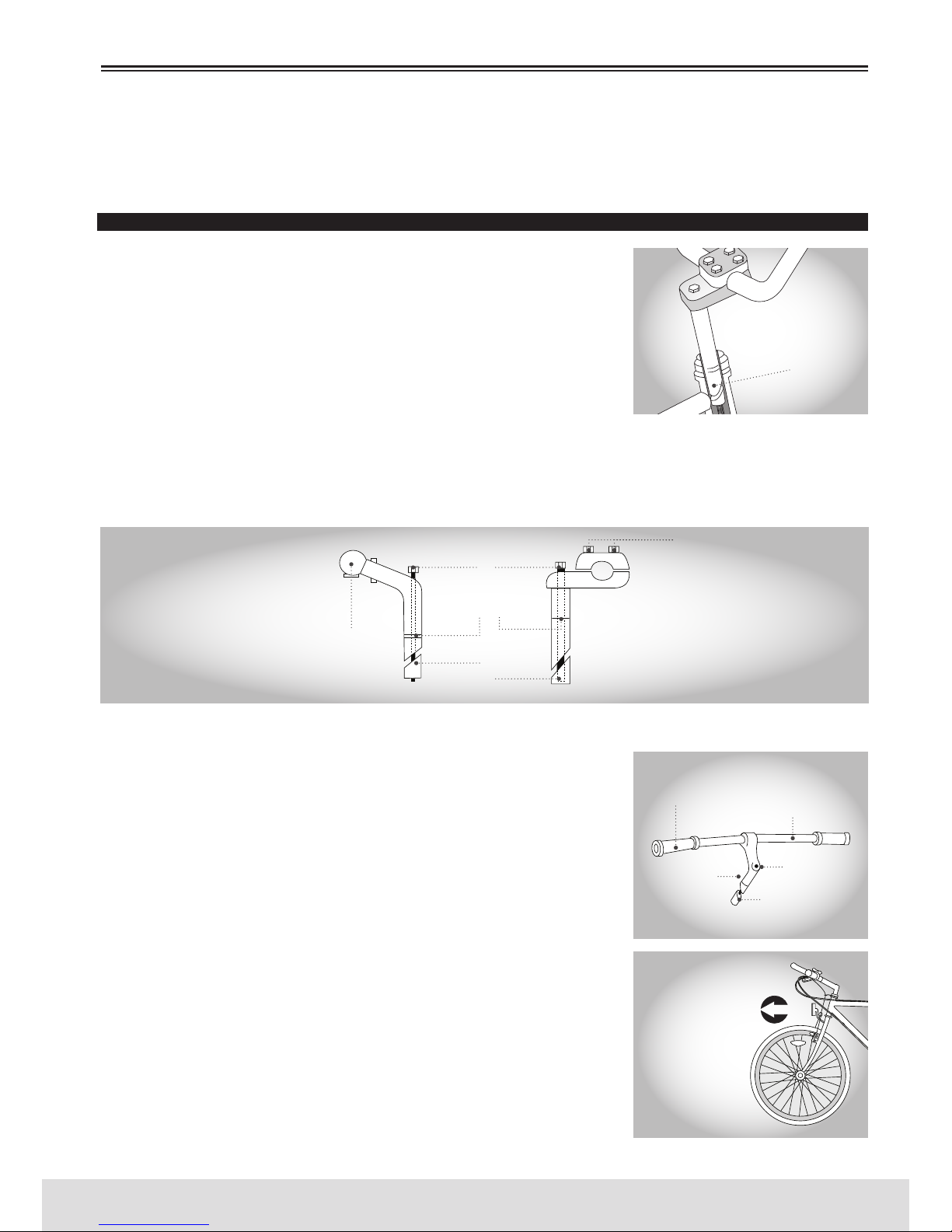
97
PORTUGUÊS
www.bergcycles.com
lateral do mesmo. Utilize um indicador de pressão de ar para pneus para controlar.
16. Volte a colocar a roda no quadro e verifique se todas as mudanças, travões e alavancas de abertura
rápida estão corretamente ajustadas.
GUIADOR E AVANÇO
AVANÇO DA DIREÇÃO - O avanço coloca-se na coluna de direção e é preso
firmemente através de um parafuso de fixação e uma cunha expansiva;
quando apertada, une-se com o interior do tubo da direção da forqueta.
Quando retirar o avanço, desaperte o parafuso do mesmo com duas ou
três voltas e depois dê-lhe um pequeno golpe para soltar a cunha do
interior. Antes de lubrificar, limpe a gordura e sujidade, e depois aplique
uma película fina de gordura à parte, incluindo na cunha, que se inserirá
no quadro. A altura do guiador pode ajustar-se para satisfazer as suas
preferências de comodidade. Se retirar o avanço da coluna de direção, verá uma marca aproximadamente 65mm acima da parte inferior com as palavras “altura máxima” ou “inserção mínima”.
Nunca ande numa bicicleta se o avanço estiver levantado de maneira a ver-se a linha de altura máxima/
inserção mínima.Se apertar demasiado o parafuso do avanço ou a montagem da caixa de direção, poderão ocorrer danos na bicicleta e/ou lesões no ciclista.
Quando voltar a ajustar o avanço, certifique-se de que o guiador está corretamente alinhado e apertado,
utilizando a chave hexagonal apropriada ou a chave Allen.
NÃO O APERTE EM EXCESSO - Comprove a segurança do guiador dentro
do avanço e o avanço dentro do tubo da direção da forqueta, colocando
a roda dianteira entre os seus joelhos e movendo o guiador para cima e
para baixo e de um lado para o outro. O guiador não deverá mover-se
quando se aplica pressão ao girar.
GUIADOR
A posição exata do guiador é uma questão de comodidade pessoal. Para
as bicicletas de montanha (MTB), a barra deveria estar aproximadamente em posição horizontal, com as extremidades apontando para
trás e ligeiramente para cima. Nas bicicletas BMX, o guiador deverá
permanecer numa posição aproximadamente reta, mas pode orientarse para trás ou para a frente ligeiramente, para sua comodidade. Nas
bicicletas MTB ou de estrada, o guiador está geralmente apertado no
avanço por um parafuso Allen ou um parafuso hexagonal. Nas bicicletas
BMX, é possível haver quatro parafusos de aperto.
Tenha em conta que se necessitar de substituir a forqueta da sua bicicleta em algum momento, deverá consultar um técnico de bicicletas
qualificado.
MANUTENÇÃO
PARAFUSO DE FIXAÇÃO DO
GUIADOR
MONTAGEM DO GUIADOR DA
BICICLETA DE MONTANHA (MTB)
CERTIFIQUE-SE DE QUE O
GUIADOR E A FORQUETA
ESTÃO VOLTADOS PARA A
FRENTE.
TENHA EM CONTA QUE A
INCLINAÇÃO CURVA DA
FORQUETA DEVE ESTAR
VOLTADA PARA A FRENTE.
PUNHO
GUIADOR
PARAFUSO
DO AVANÇO
AVANÇO
CUNHA DO
PARAFUSO DO AVANÇO
PARAFUSOS DA
BRAÇADEIRA DO
GUIADOR
PARAFUSO DO AVANÇO
MARCA DE ALTURA
MÁXIMA/INSERÇÃO MÍNIMA
CUNHA DO PARAFUSO
DO AVANÇO
MARCA DE ALTURA MÁXIMA
INSERÇÃO MÍNIMA
Page 98
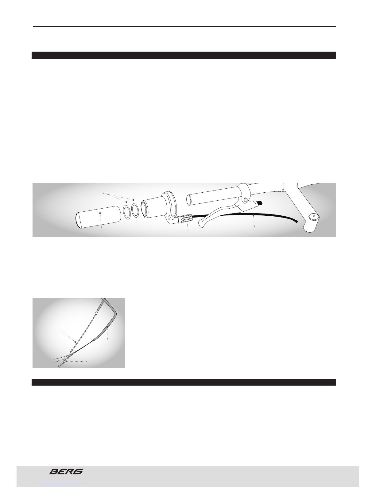
98
// MANUAL DO UTILIZADOR
PORTUGUÊS
PUNHO DE MUDANÇA DE VELOCIDADE
INSTALAÇÃO DO GRIP SHIFT ™
1. Deslize a montagem do GRIP SHIFT ™ sobre o lado esquerdo do guiador deixando espaço livre apropriado para o punho. Se for necessário, mova a manete de travão para acomodar o GRIP SHIFT ™ e o
punho do guiador.
2. Rode a montagem até que o cabo saia por debaixo da manete de travão com o espaço livre adequado
para mover a manete de travão.
3. Aperte com firmeza o parafuso de fixação recesso. O binário de torção da instalação deve ser de 2.25
N.m.
4. Deslize as anilhas plásticas no guiador. As anilhas impedem que o punho interfira com o rodar do GRIP
SHIFT ™.
5. Deslize o punho no guiador. Passe o arame interior do cabo através das espirais do cabo e do quadro, e aperte ao desviador. Certifique-se de que o cabo está na ranhura em V no parafuso de aperto
do desviador. Se for necessário cortar a espiral do cabo, certifique-se que volta a colocar o terminal na
extremidade da espiral.
6. Ajuste com o dedo indicador.
7. Deslize o GRIP SHIFT ™ traseiro sobre o lado direito do guiador e repita os passos 2-6.
8. Acione as manetes de travão dianteiro e traseiro para se assegurar de que funcionam corretamente.
Se o GRIP SHIFT ™ interfere com o movimento da manete de travão, rode a manete de travão ou o GRIP
SHIFT ™. Verifique novamente se a manete de travão funciona corretamente.
CABOS E ESPIRAIS DOS CABOS
Os cabos e as espirais são alguns dos elementos mais negligenciados
de uma bicicleta. Uma maior pressão para travar ou para mudar de velocidade são as primeiras indicações de que os cabos e espirais têm que
ser substituídos. Antes de cada utilização verifique se não há dobras ou
desgastes nos cabos e espirais.
Verifique também se a espiral está devidamente assente em cada terminal do cabo na bicicleta. Recomenda-se que os cabos e espirais sejam substituídos pelo menos uma vez em cada temporada de ciclismo
para prolongar a vida útil da sua bicicleta.
CAIXA DE DIRECÇÃO
INSPEÇÃO
O ajuste do rolamento da caixa de direção deve ser revisto todos os meses. É importante porque a caixa
de direção é o que bloqueia a forqueta no quadro e, se estiver solta, pode provocar danos ou um acidente.
Enquanto parado sobre o tubo superior do quadro com ambos os pés no chão, pressione o travão dianteiro com firmeza e a bicicleta para trás e para a frente; se detetar uma certa falta de firmeza na caixa
de direção, deverá ajustá-la. Verifique se a caixa de direção não está excessivamente apertada rodando
lentamente a forqueta para a direita e para a esquerda. Se a forqueta tende a parar ou travar em algum
MANUTENÇÃO
ANILHAS PLÁSTICAS
PUNHO TENSOR CABO
CABO BOM
DOBRA
DESGASTE
Page 99
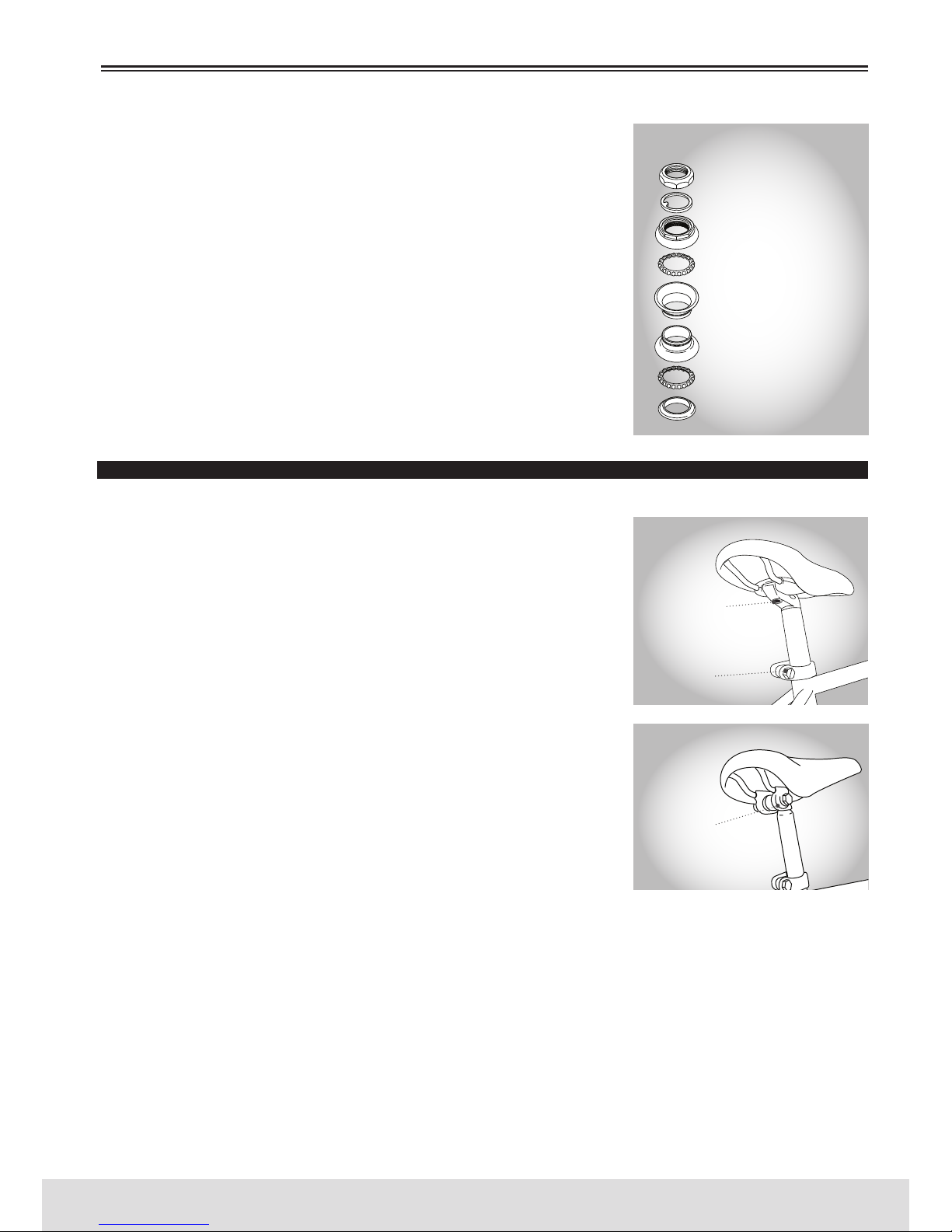
99
PORTUGUÊS
www.bergcycles.com
ponto, os rolamentos estão demasiado apertados.
Se a sua bicicleta está equipada com uma caixa de direção sem rosca,
consulte um especialista qualificado em reparações e ajustes.
AJUSTES
Desaperte a porca de segurança superior da caixa de direção ou tire-a
completamente junto com o suporte do refletor, se colocado. Rode o
copo de ajuste no sentido dos ponteiros do relógio até que esteja ajustada. Coloque novamente a anilha de segurança ou o suporte do refletor
e aperte novamente a porca de segurança com uma chave adequada.
Não aperte excessivamente ou danificará o rolamento. Certifique-se
sempre de que a caixa de direção está ajustada corretamente e que a
porca de segurança da caixa de direção está completamente apertada, antes de utilizar a bicicleta. Se apertar o parafuso do avanço ou a
montagem da caixa de direção em excesso, poderá provocar danos na
bicicleta e/ou lesões no ciclista.
SELIM E ESPIGÃO DO SELIM
INSPEÇÃO
O parafuso de fixação do selim e o parafuso de fixação do espigão do
selim devem ser revistos mensalmente para estarem bem colocados e
apertados. Se tirar o espigão do selim do quadro, verá uma marca aproximadamente 65mm acima da parte inferior com as palavras “altura
máxima” ou “inserção mínima”.
Para evitar danos no espigão do selim, no quadro ou possivelmente no
ciclista, a marca de inserção mínima deve estar dentro do quadro.
LUBRIFICAÇÃO
Tire o espigão do selim do quadro e limpe as manchas de gordura, ferrugem ou sujidade. Depois aplique uma película fina de gordura nova
na parte que se insere no quadro. Insira, ajuste a aperte novamente o
espigão do selim no quadro.
AJUSTES
Conforme mencionado anteriormente, o selim pode ajustar-se quanto
à altura, ao ângulo e à distância do guiador, para satisfazer as preferências de cada ciclista.
O ângulo do selim é uma questão de preferência pessoal, mas a posição
mais cómoda geralmente é quando a parte superior do selim está quase
paralela ao piso, ou ligeiramente levantada à frente. O selim também pode ser ajustado deslizando para
a frente ou para trás ao largo dos carris de montagem para alcançar o guiador com maior comodidade.
Quando colocar o espigão do selim, posicione-o na braçadeira debaixo do selim e coloque o mesmo no
quadro sem apertar. Ajuste-o no ângulo e posição desejados, e aperte o mecanismo da braçadeira.
Existem dois tipos de braçadeiras de selim de uso frequente. A mais comum emprega uma braçadeira de
aço com porcas hexagonais em cada lado para apertar. O outro tipo, conhecido como braçadeira micra
ajustável, utiliza um único parafuso de fixação de cabeça Allen montado verticalmente para apertar.
Depois de colocar o selim na posição desejada no espigão, ajuste a altura ao nível requerido e aperte o
parafuso de fixação. Tenha em conta que o tipo de parafuso de fixação pode ser um parafuso hexagonal,
um parafuso de cabeça Allen ou um mecanismo de abertura rápida. O funcionamento do mecanismo de
abertura rápida do espigão do selim é o mesmo para os cubos com sistema de abertura rápida.
Consulte a pág. 104 à 107.
MANUTENÇÃO
PORCA DE SEGURANÇA
ANILHA DE SEGURANÇA
COPO/CONE DE AJUSTE
RETENTOR DE ESFERAS
COPO DE DIREÇÃO SUPERIOR
COPO DE DIREÇÃO INFERIOR
RETENTOR DE ESFERAS
ANEL DA COROA
CAIXA DE DIREÇÃO STANDARD
PARAFUSO DE FIXAÇÃO
DO SELIM
PORCA DE FIXAÇÃO
DO SELIM
ESPIGÃO DO SELIM MICRO AJUSTÁVEL
ESPIGÃO DO SELIM STANDARD
PARAFUSO DE FIXAÇÃO DO
ESPIGÃO DO SELIM
Page 100
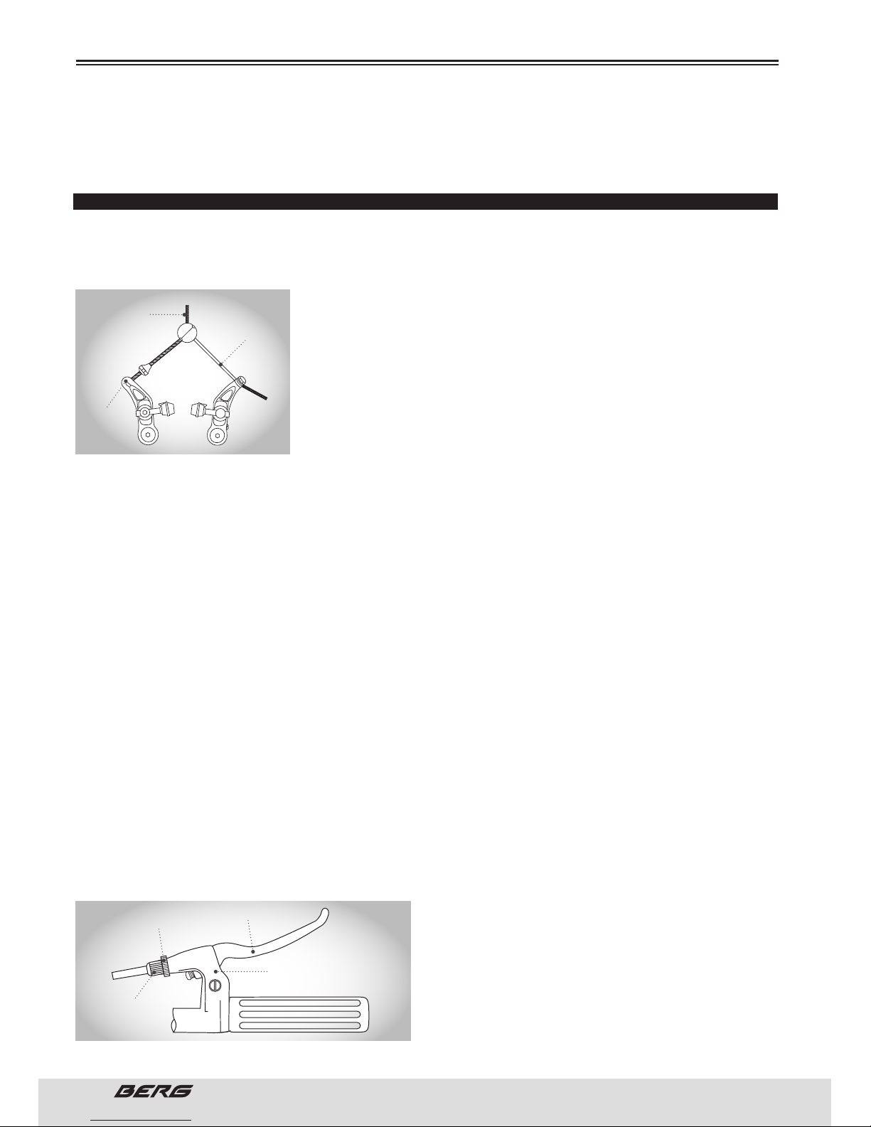
100
// MANUAL DO UTILIZADOR
PORTUGUÊS
MANUTENÇÃO
Verifique a segurança agarrando o selim e tentando rodá-lo para os lados. Se mover, deverá apertar
mais o parafuso de fixação. Lembre-se de que a marca de inserção mínima deve permanecer dentro da
montagem do quadro.
TRAVÕES
O ajuste e funcionamento correto dos travões da bicicleta é extremamente importante para um funcionamento seguro. Os travões devem ser revistos para que funcionem de maneira eficaz, antes de cada saída.
A inspeção frequente dos ajustes é necessária porque os cabos esticam e os calços de travão gastam-se
com o uso.
Nunca ande numa bicicleta cujos travões não funcionem corretamente.
Existem dois tipos de travões manuais de bicicleta, de uso frequente:
com calibradores de tração lateral e com calibradores cantilever. Ambos
utilizam uma manete montada no guiador que controla um cabo encarregue de ativar o travão. Os travões de tração lateral estão montados no
quadro ou forqueta através de um único ponto de pivô.Os travões cantilever utilizam os braços de pivô, cada um montado em pivôs separados
em cada lado do quadro/forqueta.
INSPEÇÃO
O ajuste das manetes de travão deve ser revisto, pelo menos, a cada três meses. Devem colocar-se
numa posição cómoda, facilmente acessível para as mãos do ciclista, e devem ficar imóveis no guiador.
Algumas manetes de travão utilizam um parafuso de regulação de alcance, que se pode modificar de
acordo com a distância entre o punho do guiador e a manete, consoante seja necessário. Os calços de
travão devem ser revistos para ter a certeza de que estão bem posicionadas e apertadas, antes de cada
saída de bicicleta, bem como os diversos parafusos e porcas, pelo menos a cada três meses. Pressione
as manetes de travão para se assegurar de que funcionam sem percalços e que os calços de travão
pressionam com força suficiente sobre os aros para parar a bicicleta. Deve haver um espaço livre de
aproximadamente 1 a 2mm entre cada calço e o aro quando os travões não são acionados. Os calços de
travão devem estar corretamente centrados para proporcionar o máximo contacto com o aro. Substitua
os calços de travões se estiverem muito desgastados de modo a que as ranhuras e os padrões não se
vejam. Os arames de cabo do travão devem ser revistos para ver se estão enrolados, enferrujados, se
existem outros danos. Se os cabos estão danificados, devem ser substituídos. Alguns travões têm um
mecanismo de abertura rápida para permitir que a roda seja retirada mais facilmente. De cada vez que
ajustar os travões, certifique-se de que o mecanismo de abertura rápida está na posição fechado.
Nunca utilize uma bicicleta a menos que a alavanca de abertura rápida esteja firmemente bloqueada na
posição fechado.
LUBRIFICAÇÃO
A manete de travão e os pontos de pivôs do calibrador do travão deveriam olear-se com 2 ou 3 gotas
de óleo fino, pelo menos a cada três meses, para assegurar um funcionamento suave e para reduzir o
desgaste. Os cabos devem olear-se em todo o seu comprimento, depois de lhes tirar as espirais, pelo
menos a cada seis meses. Oleie sempre os cabos novos antes de os instalar.
AJUSTES
Os ajustes menores dos travões podem ser realizados
através do tambor de regulação do cabo, geralmente localizado no braço do cabo superior. Para ajustar,
pressione os calços de travão contra o aro, desaperte
a porca de segurança e rode o regulador. O espaço
livre entre o calço de travão e o aro deve ser, no máximo, 2mm. Uma vez alcançado o ajuste correto, aperte
CABO DE TRAVÃO
BIFURCADO
BRAÇO DO
TRAVÃO
CABO DE
TRAVÃO
TRAVÕES CANTILEVER
PORCA DE
SEGURANÇA
MANETE DE TRAVÃO
AMBOR DE REGULAÇÃO
DO CABO
COBERTURA DA
MANETE DE TRAVÃO
 Loading...