

Page 1
MANUALE UTENTE
USER’S MANUAL
INSTRUKCJA OBSŁUGI
PANNELLO DI
CONTROLLO
REMOTO REC 07
REMOTE CONTROL
PANEL REC 07
PROGRAMATOR
REC 07
PAUSE
AUTO/MAN
RESET
/
-
+
Page 2

2
Gentile cliente,
Beretta, da sempre impegnata a soddisfare le richieste della propria Clientela, pone tutta la
sua esperienza e competenza nella realizzazione di tutti i suoi apparecchi.
Per consentirLe di familiarizzare con la Sua nuova caldaia e farLe apprezzare con la massima soddisfazione i vantaggi del riscaldamento autonomo e della produzione istantanea di
acqua calda, abbiamo realizzato questo manuale di semplice consultazione.
Le chiediamo di leggerlo attentamente, perchè seguendo le nostre informazioni ed i nostri
consigli potrà utilizzare correttamente il Suo nuovo apparecchio e provvedere ad una sua
puntuale manutenzione.
Al termine della lettura, lo conservi con cura, potrà esserLe utile per ogni ulteriore consultazione.
Per qualsiasi ulteriore necessità, potrà contattare il nostro “SERVIZIO CLIENTI”.
Telefonando al 199.13.31.31 (vedi tariffe sul retro copertina), potrà mettersi in contatto con
uno dei nostri operatori qualicati, che sarà in grado di fornirLe tutte le informazioni sul funzionamento del Suo apparecchio e sulla nostra intera gamma di prodotti e servizi e che sarà
pronto per accogliere tutti i Suoi suggerimenti ed osservazioni.
In caso di assenza dei nostri operatori, una messaggeria telefonica accoglierà la Sua chiamata per permetterci di risponderLe appena possibile.
Le ricordiamo che Beretta dispone di un’Organizzazione di Assistenza composta da perso-
nale qualicato pronto ad intervenire ad ogni Sua chiamata.
Per contattare il Centro di Assistenza Tecnica a Lei più vicino, potrà telefonare al numero
199.12.12.12 (vedi tariffe sul retro copertina) che La metterà in contatto con il Centro di Assistenza Tecnica operante nella Sua zona.
IT
EN
Dear Client,
Beretta has always been committing itself to comply with the demands of its own Clients and
uses all its experience and competence for the realization of all its appliances.
We made this advisory manual in order to let you become familiar with your new boiler and
appreciate with maximum satisfaction the advantages of autonomous heating and instantaneous hot water production.
Please read carefully because, following our information and advice, you would be able to
use properly your new appliance and provide for its proper maintenance.
Having nished reading, you should keep it with care; it could be useful for a later consul-
tation.
Page 3
3
INDICE
1 INFORMAZIONI GENERALI pag. 5
2 ACCENSIONE pag. 8
3 UTILIZZO DEL PANNELLO DI CONTROLLO REMOTO pag. 10
3.1 Funzioni base (coperchio chiuso) pag. 10
3.1.1 Scelta del modo di fuzionamento pag. 11
Funzione estate pag. 11
Funzione inverno pag. 11
Funzionamento manuale - TERMOSTATO AMBIENTE pag. 11
Funzionamento notturno pag. 12
Funzionamento automatico CRONOTERMOSTATO pag. 12
3.1.2 Selettore correzione temperatura ambiente impostata pag. 13
3.1.3 Interruzione del tempo di riscaldamento pag. 13
Pausa pag. 13
Vacanze pag. 14
3.1.4 Funzione di sblocco pag. 16
3.2 Funzioni avanzate (coperchio aperto) pag. 17
3.2.1 Impostazione della lingua pag. 18
3.2.2 Selezione dei menu disponibili pag. 19
3.2.3 Modica dei dati preimpostati pag. 19
3.2.4 Descrizione dei menu pag. 20
Utente pag. 20
Visualizzare pag. 21
Ora+giorno pag. 22
Progr-Risc (PROGRAMMAZIONE RISCALDAMENTO) pag. 22
Progr-ACS (PROGRAMMA ACQUA CALDA SANITARIA) pag. 27
4 SPEGNIMENTO pag. 31
5 ANOMALIE pag. 32
6 VARIE pag. 36
Il pannello di controllo remoto è conforme a:
- Direttiva Compatibilità Ettromagnetica 2004/108/CEE
- Direttiva Bassa Tensione 2006/95/CEE
0694
In some parts of the manual, these symbols are used:
ATTENTION = for actions that require particular caution and proper training
FORBIDDEN =for actions that MUST NOT be performed
Page 4
4
CONTENTS
1 GENERAL INFORMATIONI pag. 5
2 SWITCHING ON pag. 8
3 USING THE REMOTE CONTROL PANEL pag. 10
3.1 Basic functions (dashboard cover closed) pag. 10
3.1.1 Selecting the operating mode pag. 11
Summer mode pag. 11
Winter mode pag. 11
Manual operating mode – ROOM THERMOSTAT pag. 11
Night operating mode pag. 12
Automatic operating mode PROGRAMMABLE
ROOM THERMOSTAT pag. 12
3.1.2 Selector for adjusting the room temperature set pag. 13
3.1.3 Interrupting the heating schedule pag. 13
Pause pag. 13
Holiday pag. 14
3.1.4 Unblocking function pag. 16
3.2 Advanced functions (dashboard cover open) pag. 17
3.2.1 Setting the language pag. 18
3.2.2 Selecting the menus available pag. 19
3.2.3 Adjusting the preset data pag. 19
3.2.4 Description of menus pag. 20
User pag. 20
Displaying pag. 21
Time+day pag. 22
HTG-PROG (HEATING SCHEDULE) pag. 22
HOTW-PROG (DOMESTIC HOT WATER SCHEDULE) pag. 27
4 SWITCHING OFF pag. 31
5 FAULTS pag. 32
6 MISCELLANEOUS pag. 36
The remote control panel complies with the following Directives:
- Electromagnetic compatibility Directive 2004/108/CEE
- Low-voltage Directive 2006/95/CEE
0694
In some parts of the manual, these symbols are used:
ATTENTION = for actions that require particular caution and proper training
FORBIDDEN =for actions that MUST NOT be performed
Page 5

5
IT EN
1 INFORMAZIONI GENERALI
PER UN USO CORRETTO DEL PANNELLO DI CONTROLLO REMOTO VI INVITIAMO A LEGGERE ATTENTAMENTE IL
CONTENUTO DEL PRESENTE MANUALE.
AVVERTENZE
1) Il pannello di controllo remoto deve essere installato nel locale a voi più accessibile per il controllo della temperatura ambiente (generalmente è il soggiorno).
2) Per consentire una più agevole lettura
del display, il pannello di controllo deve
essere posizionato, come prevedono le
normative, a 1,5 metri da terra.
3) Il pannello di controllo remoto è alimentato in bassa tensione direttamente dalla
caldaia. Al suo interno è comunque presente una batteria tampone che garantisce il mantenimento delle impostazioni
utente anche in caso di black-out o di interruzione del collegamento caldaia.
4) Il pannello di controllo deve essere tassativamente tenuto lontano da fonti di calore o da correnti d’aria: queste possono
compromettere la bontà delle rilevazioni
del termostato ambiente incorporato nel
pannello stesso.
5) Non aprire per nessun motivo il pannello:
il suo funzionamento non necessita di alcuna manutenzione.
6) Non eseguire pressioni sul vetro del display a cristalli liquidi: tale operazione
potrebbe danneggiare il vetro stesso e
causare problemi di visualizzazione.
7) Per la pulizia del display servirsi esclusivamente di un panno asciutto: eventuali
inltrazioni potrebbero danneggiare i cristalli liquidi.
MODALITÁ DI UTILIZZO
Il pannello di controllo remoto prevede tre
modalità di utilizzo:
1) TERMOSTATO AMBIENTE
Il pannello di controllo si preoccupa di man-
tenere costante la temperatura dell’ambiente secondo i parametri inseriti dall’utente.
2) CRONOTERMOSTATO
In questo caso sarà per voi possibile una
gestione più rafnata del riscaldamento domestico in quanto potrete decidere
come e quando la caldaia entrerà in funzione per riscaldare gli ambienti.
3) CONTROLLO CALDAIA
In questa modalità di utilizzo il pannello
di controllo permette di gestire il funzionamento della caldaia senza controllo della
temperatura ambiente. In questo caso è
necessario utilizzare un termostato ambiente esterno.
1 GENERAL INFORMATION
FOR A PROPER USE OF THE REMOTE
CONTROL PANEL, PLEASE READ CAREFULLY THE ENTIRE CONTENTS OF THIS
MANUAL.
WARNINGS
1) The remote control panel has to be installed in the room most accessible for che-
cking the temperature of the environment
(normally the living room).
2) In order to read the display more easily,
the remote control panel has to be placed,
according to standards, at a height of 1.5
metres from the oor.
3) The control panel is supplied with low-voltage directly by the boiler. Nevertheless,
it contains a buffer battery, which guarantees the maintenance of the user settings
even when there is a blackout or a break
in the boiler connection.
4) It is essential that the control panel be kept
away from heat sources and draughts:
these may affect the accuracy of the room
thermostat incorporated in the panel.
5) Do not attempt to open the panel: it requires no maintenance.
6) Do not press against the surface of the
liquid crystal display: this could damage
the surface itself and cause viewing problems.
7) To clean the display, simply wipe with a dry
cloth: any inltrated liquid could damage
the liquid crystals.
HOW TO USE
The remote control panel has three operating modes:
1) ROOM THERMOSTAT
The control panel keeps the temperature
of the environment constant, based on
the settings made by the user.
2) PROGRAMMABLE ROOM THERMOSTAT
In this mode, advanced settings are avai-
lable; you can decide how and when the
boiler will switch on to heat up the environment.
3) BOILER CONTROL
In this mode, the control panel works only
with the boiler controls; it does not con-
trol the temperature of the environment.
For that, you should use an external room
thermostat.
Page 6
6
IT
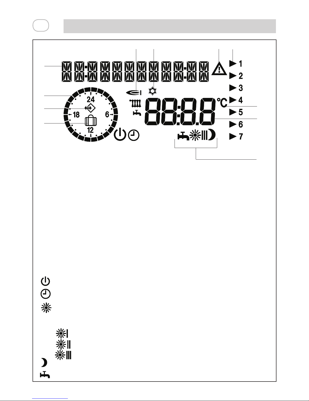
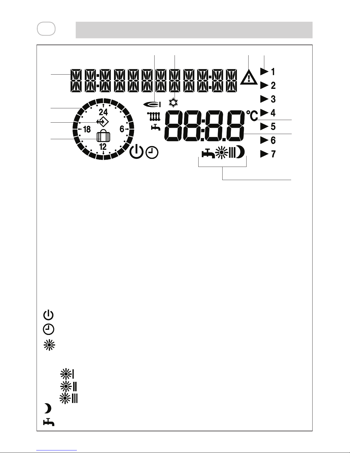
COSA VISUALIZA IL DISPLAY
A - Zona per messaggi di testo e visualizzazione ora
B - Orologio 24h per visualizzazione del programma riscaldamento attuale
C - Simbolo di comunicazione con caldaia, indica che è in corso uno scambio di
dati tra caldaia e pannello controllo remoto
D - Simbolo di funzione vacanze attiva
E - Simbolo di bruciatore acceso in riscaldamento o sanitario
F - Simbolo protezione antigelo attiva
G - Simbolo di modica: indica che è possibile variare i valori impostati
H - Freccia indicante il numero del giorno corrente
I - Gradi centigradi
J - Visualizzazione dei valori impostati
K - Simboli indicanti il modo di funzionamento
Stand-by/OFF (Il riscaldamento e l’acqua calda sono spenti, solo la funzione
antigelo resta attiva)
Funzionamento automatico - cronotermostato
Funzionamento manuale (riscaldamento continuo a temperatura impostata -
T-AMB1) - termostato ambiente
In programmazione riscaldamento i simboli corrispondono a:
1° fascia oraria di funzionamento
2° fascia oraria di funzionamento
3° fascia oraria di funzionamento
Funzionamento notturno (riscaldamento a temperatura ridotta)
Funzionamento estivo (riscaldamento spento, solo acqua calda)
A
B
C
D
E
F G
H
I
K
J
Page 7
7
EN
DESCRIPTION OF DISPLAY
A - Text messages and time display eld
B - Daily current heating schedule
C - Communication with the boiler symbol, indicates that there is an exchange of
data between the boiler and the remote control panel
D - Holiday function symbo
E - Symbol for burner operating in the heating or sanitary function
F - Anti-freeze protection symbol
G - Modication symbol: indicates that the values set may vary
H - Arrow indicating the current day number
I - Centigrade degrees
J - Displaying the values set
K - Operating mode symbols
Stand-by/OFF (The heating and domestic hot water are off, only the anti-freeze
function is active)
Automatic operating mode – programmable room thermostat
Manual operating mode (continuous heating at selected temperature - T-AMB1)
– room thermostat
For the heating schedule, the symbols correspond to:
1st operating time band
2nd operating time band
3rd operating time band
Night operating mode (reduced temperature heating)
Summer operating mode (heating off, domestic hot water only)
A
B
C
D
E
F G
H
I
K
J
Page 8
IT EN
8
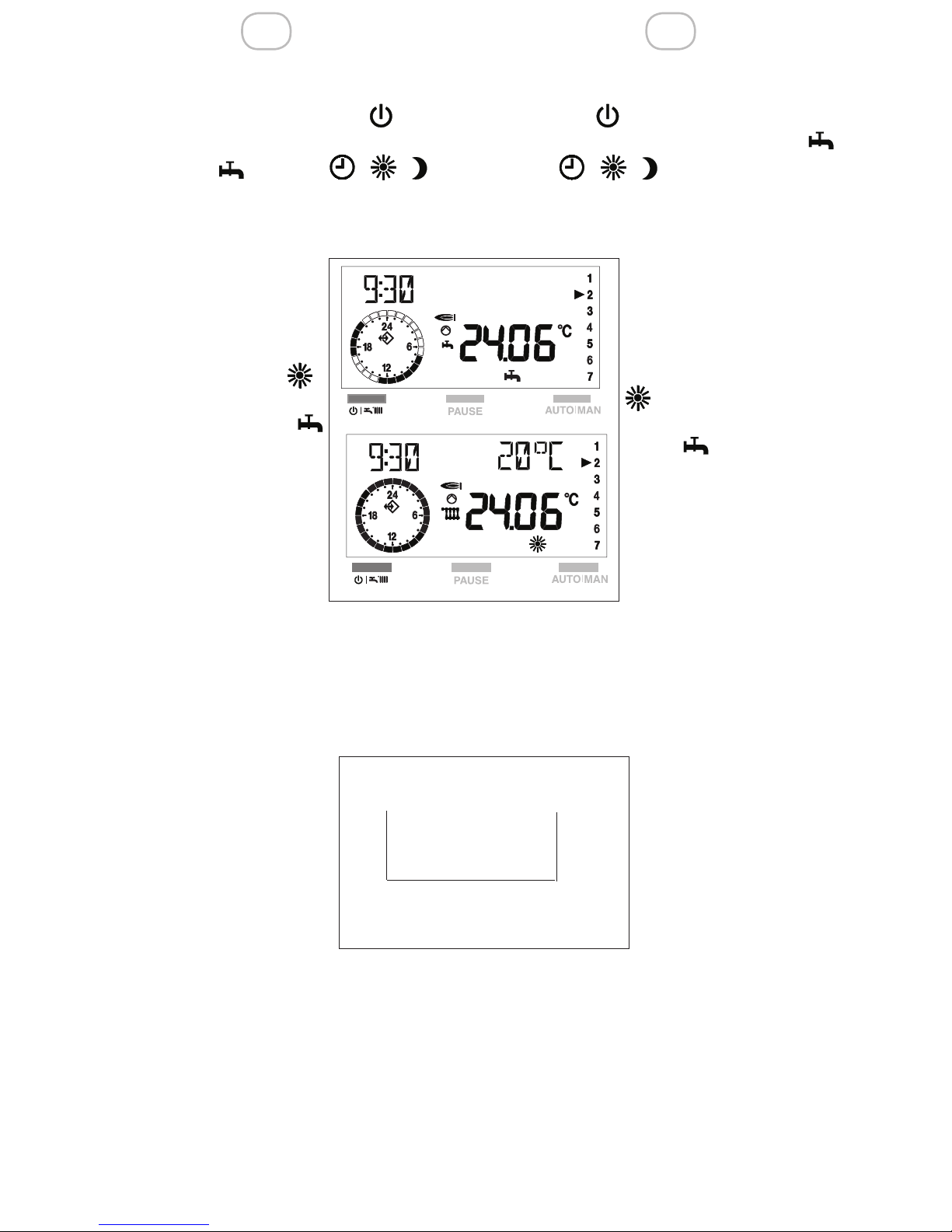
2 ACCENSIONE
Con lo sportellino del pannello di controllo
remoto chiuso, premere il tasto no a
visualizzare il tipo di funzionamento desiderato, estate o inverno - - (il
display visualizza uno dei modi di funzionamento invernale disponibili - vedi paragrafo “Funzione inverno”).
Il pannello di controllo remoto si attiva nello stato in
cui si trovava prima dello
spegnimento: se si trovava
nella funzione inverno ,
si riaccenderà in inverno;
se si trovava in estate
, si attiverà in questo stato.
La caldaia effettuerà la
fase di avviamento e resterà in funzione no a quando saranno raggiunte le
temperature impostate.
Nel caso si vericassero
anomalie di accensione o di funzionamento, la caldaia effettuerà un “arresto di sicurezza” e sul pannello di controllo verrà
visualizzato un codice anomalia.
Per ripristinare le condizioni
di avviamento:
- premere contemporaneamente i tasti PAUSE+
AUTO-MAN sul pannello
di controllo remoto.
Il ripetersi di blocchi suggerisce l’intervento del Centro di
Assistenza Tecnica.
Per informazioni dettagliate riferirsi al capitolo “Anomalie”.
2 SWITCHING ON
With the dashboard cover closed, push
the button until you see on the display
the desired operating mode, summer or
winter - - (the display shows one
of the available winter operating modes –
see section “Winter operating mode”).
The remote control panel
starts up in the operating
mode in which was set to
work before it was switched
off: if it was in winter mode
, it starts up in winter
mode; if it was in summer
mode , it starts up in
summer mode.
The boiler will start up and
continue to operate until the
selected temperatures are
reached.
If faults occur on starting
or operating, the boiler will make a “safety
stop” and a fault code will appear on the
display.
To reset the boiler:
- press the PAUSE and
AUTO-MAN buttons simultaneously on the remote control panel.
If the blocking fault occurs
over again, contact the
Service Center.
For detailed information, see section
“Faults”.
PAUSE
AUTO I MAN
+
RESET
Page 9

9
IT EN
ATTENZIONE
Il pannello di controllo remoto svolge funzioni diverse a seconda che lo sportellino
frontale sia aperto o chiuso.
A coperchio chiuso sono disponibili le
funzioni base che consentono all’utente
di accendere e spegnere la caldaia, scegliere il tipo di funzionamento desiderato
e sbloccare la caldaia dopo un’anomalia.
Molto interessante è la presenza del selettore di modica della temperatura ambiente, che permette di correggere in maniera
molto semplice e veloce, il valore di temperatura ambiente impostato di ± 5°C.
A coperchio aperto sono disponibili funzioni più avanzate come, per esempio,
modica delle temperature, impostazione
del programma riscaldamento e altro (vedi
capitolo dedicato).
ATTENTION
The remote control panel carries out different functions, depending on the dashboard cover being open or closed.
With the dashboard cover closed, basic
functions are available, which allow the
user to switch on or off the boiler, choose
the desired operating mode and unblock
the boiler when a fault occurred.
It is very interesting the presence of the
selector for adjusting the room temperature, which facilitates the correction of the
room temperature set with ± 5°C.
With the dashboard cover open, advanced functions are available, as for instance
regulating temperatures, setting the heating schedule and others (see dedicated
chapter).
Page 10
IT EN
10
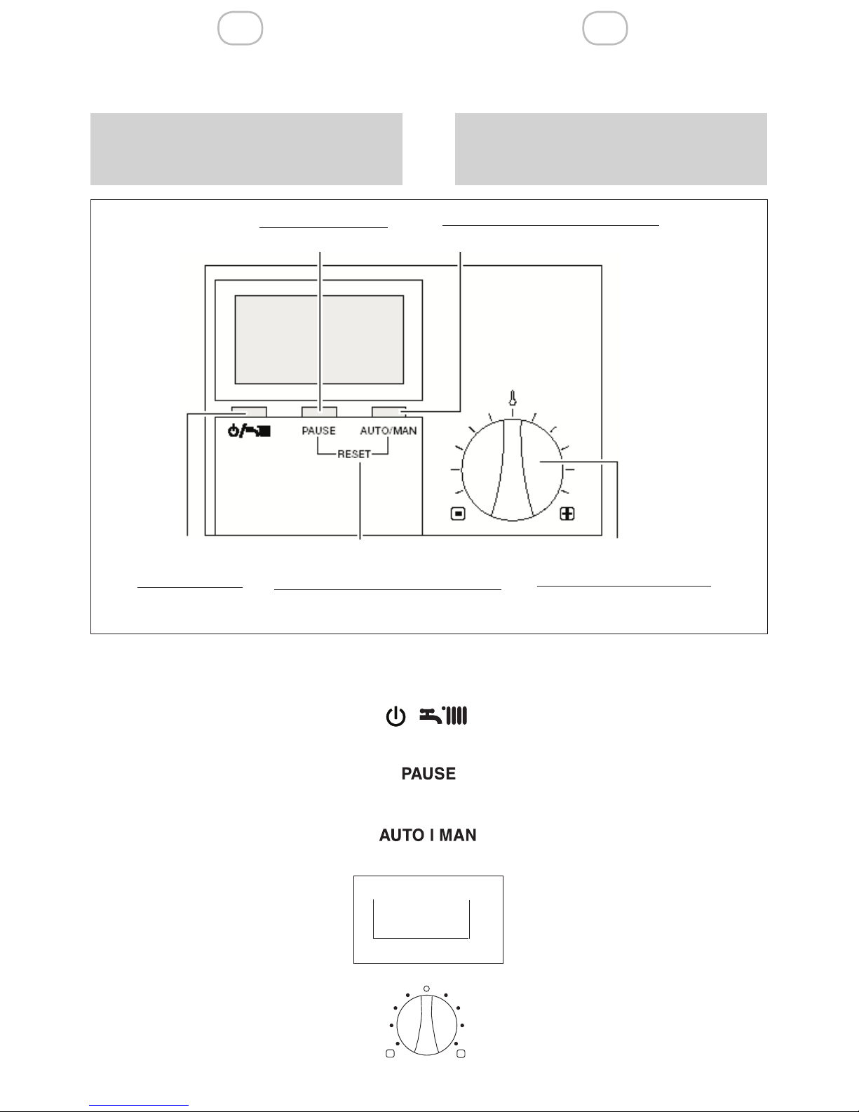
Con il coperchio chiuso sono attivi i seguenti tasti:
Acceso/spento, selezione regimi di
funzionamento
Pause/Vacanze (Interruzione del tempo
di riscaldamento)
Nella funzione inverno consente la
scelta dei modi di funzionamento:
manuale, notturno e automatico
Premuti contemporaneamente generano uno sblocco della caldaia
(RESET)
Selettore per la correzione di ±5°C
della temperatura ambiente impostata.
With the cover closed, the following buttons are enabled:
On/Off, selects the operating mode
Pause/Holiday (Interrupts the heating
schedule)
In winter mode, selects the operating
mode: manual, night or automatic
Pressed simultaneously, they un-
block the boiler (RESET)
Selector for adjusting the room
temperature set with ±5°C.
3 UTILIZZO DEL PANNELLO
DI CONTROLLO REMOTO
3.1 Funzioni base
(coperchio chiuso)
3 USING THE REMOTE CONTROL PANEL
3.1 Basic functions (dashboard cover closed)
l
Testo pausa/vacanze
Pause/holiday button
Funzionamento manuale/automatico
Manual/Automatic operating mode
Acceso/Spento
Estate/Inverno
On/Off
Summer/Winter
Reset anomalie (premere contem-
poraneamente i due tasti)
Resetting faults (press both keyssimul-
taneously)
±5°C rispetto alla temperatura
ambiente impostata
±5°C given the room tempera-
ture set
PAUSE
AUTO I MAN
+
RESET
Page 11
11
IT EN
3.1.1 Scelta del modo di
funzionamento
FUNZIONE ESTATE
Solo acqua sanitaria
Per attivare la funzione esta-
te, premere il tasto
no a visualizzare sul display
il simbolo “ “.
Per modicare i valori di temperatura acqua sanitaria riferirsi al MENU UTENTE (paragrafo 3.2.4.
sezione dedicata “T-ACS”).
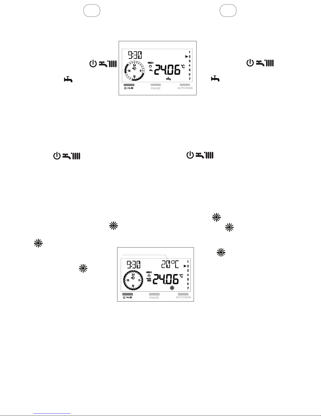
FUNZIONE INVERNO
Acqua calda sanitaria + riscaldamento.
Per attivare la funzione inverno premere il
tasto “ ”.
Per operare la scelta del tipo di funzionamento invernale, premere il tasto AUTO/
MAN no a visualizzare sul display il simbolo corrispondente alla funzione desiderata.
Il display visualizza uno dei tre modi di funzionamento invernale disponibili:
Funzionamento manuale
Quando sul display è attivo il simbolo “
”, il pannello di controllo
remoto funziona come TER-
MOSTATO AMBIENTE.
Nella funzione “ ” si ha un
tipo di funzionamento “manuale”, cioè indipendente
dalle fasce orarie impostate
nella programmazione riscaldamento (paragrafo 3.2.4.
sezione dedicata PROGR-RISC).
Otteniamo che il riscaldamento funziona
in continuo alla temperatura scelta (vedi
MENU UTENTE ).
Per modicare il valore di temperatura
ambiente, riferirsi al capitolo “Modica dei
dati preimpostati” paragrafo 3.2.3, sezione
dedicata “T-AMB”.
3.1.1 Selecting the operating
mode
SUMMER MODE
Domestic hot water only
To select summer operating
mode, press the button until you see on the display
the “ “ symbol.
To adjust the domestic hot water
temperature, see USER MENU
(paragraph 3.2.4. “T-DHW” de-
dicated section)
WINTER MODE
Domestic hot water + heating.
To select the winter operating mode, press
the “ ” button.
To select the desired winter operating
mode, press the AUTO/MAN button until
you see the corresponding symbol on the
display.
The display shows one of the available
winter operating modes:
Manual mode
When the symbol “ ”, is displayed, the
remote control panel operates as ROOM
THERMOSTAT.
In the “ ” operating mode, the
boiler works “manually”, that is
to say independently of the time
bands set in the heating schedule (paragraph 3.2.4. HTG-PROG
dedicated section). As a result,
the heating works continuously
at the selected temperature (see
USER MENU).
To modify the room temperature, see section “Adjusting the preset data” paragraph
3.2.3, “T-ROOM” dedicated section.
T-AMB1/T-ROOM DES1
Page 12
IT EN
12
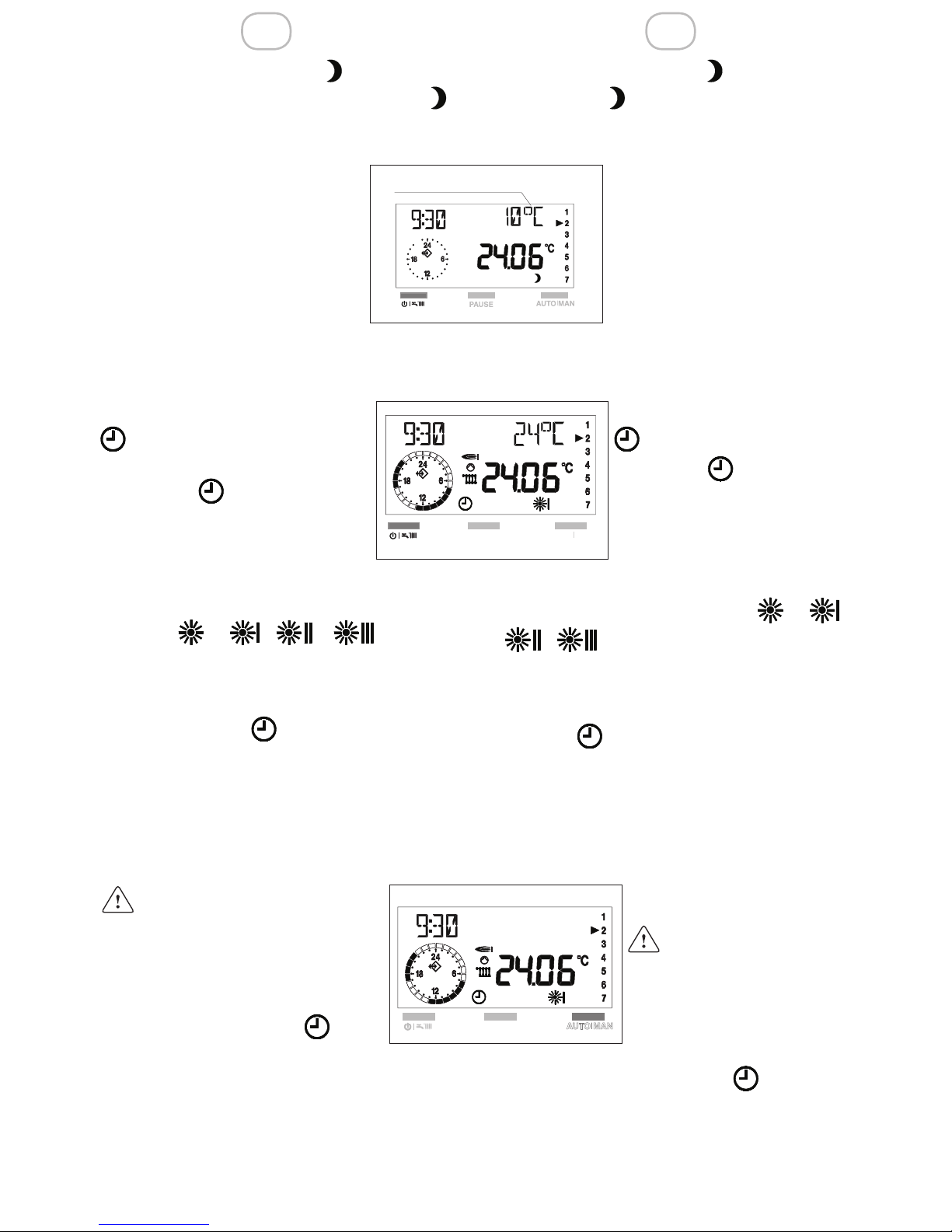
Night operating mode
When the “ ”,symbol is displayed, the
heating is off.
he heating function will enable only if the
room temperature falls below
the reduced temperature set
(T-REDUCED - see USER
MENU, paragraph 3.2.4)..
To adjust the reduced temperature values, see chapter
“Adjusting the preset data”
paragraph 3.2.3., “T-REDU-
CED” dedicated section).
Automatic operating mode
When the “ ”, s displayed,
the remote control panel
operates as PROGRAMMA-
BLE ROOM THERMOSTAT,
given the heating time bands
scheduled. The time bands are three and
they identify with the symbols: e -
To adjust them, see the paragraph 3.2.4
“HTG-PROG” dedicated section.
In the “ “ operating mode, the boiler
works “automatically”.
To adjust the room temperature values,
see chapter “Adjusting the preset data”
paragraph 3.2.3., “T-ROOM” dedicated
section.
To return to the automatic operating mode
after a period of manual functioning, you
need to press the
button AUTO/MAN
until the display shows the“ ” symbol.
Funzionamento Notturno
Quando sul display è attivo il simbolo “
”, il riscaldamento è spento.
Il funzionamento si attiverà solo se la temperatura ambiente scende al di
sotto delle temperatura ridotta
impostata (T-RIDOTTA - vedi
MENU UTENTE, paragrafo
3.2.4).
Per modicare il valori di temperatura ridotta, riferirsi al capitolo
“Modica dei dati preimpostati”
paragrafo 3.2.3., sezione dedicata “T-RIDOTTA”).
Funzionamento automatico
Quando sul display è attivo il
simbolo “ ”, il pannello di
controllo remoto funziona come
CRONOTERMOSTATO secondo le fasce orarie impostate in
programmazione riscaldamento.
Le fasce orarie sono 3 e si identicano con
i simboli: e - Per la loro programmazione riferirsi al paragrafo 3.2.4 sezione dedicata “ PROGRRISC”.
Con la funzione “ “ si ha un funzionamento “automatico” della caldaia.
Per modicare i valori di temperatura ambiente, riferirsi al capitolo “Modica dei dati
preimpostati” paragrafo 3.2.3., sezione
dedicata “T-AMB”).
Per ritornare al funzionamento automatico, dopo un
periodo funzionamento in
manuale, è necessario agire
sul tasto AUTO/MAN no a
visualizzare nuovamente sul
display il simbolo “ ”.
T-RIDOTTA/T-REDUCED
Page 13
13
IT EN
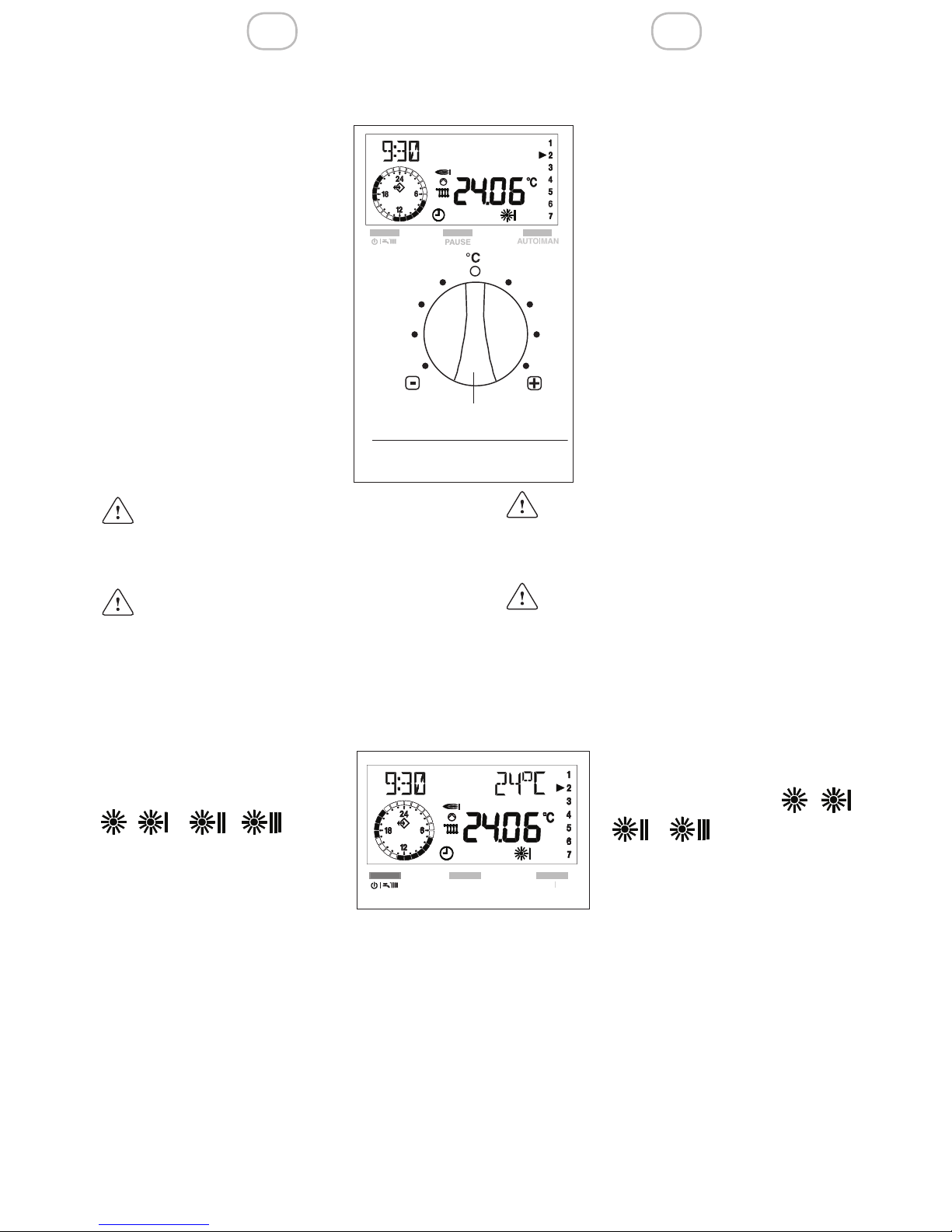
3.1.2 Selector for adjusting the
room temperature set
In the manual and automatic
operating modes, the heating
function depends on the room
temperature values set.
These values can be adjusted
with ± 5°C by turning the selec-
tor – see gure.
To adjust the temperature, proceed as follows:
- to increase the temperature set, turn the selector to
the right,
- to decrease the temperature set, turn the selector to
the left.
It is not possible to use
the selector for adjusting the domestic hot water temperature.
The modication does not produce
any effect on the reduced temperature set (night operating mode).
3.1.3 Interrupting the heating
schedule
PAUSE
The PAUSE function is active only in the and e -
- - operating mode.
During this phase, the boiler
does not operate and it will
start over when the PAUSE
time band set is nished or when the room
temperature falls under the reduced temperature set.
3.1.2 Selettore correzione temperatura ambiente impostata
Nei modi di funzionamento
manuale e automatico, il riscaldamento dipende dalle
temperature ambiente impostate.
Queste temperature pos-
sono essere modicate di ±
5°C agendo sul selettore -
vedi gura.
Per correggere la temperatura operare come segue:
- ruotare il selettore verso
destra per incrementare
la temperatura impostata,
- ruotare il selettore verso
sinistra per diminuire il valore.
Non è possibile utilizzare il selettore per modicare la temperatura dell’acqua sanitaria.
La correzione non inuisce sulla
temperatura ridotta impostata (funzionamento notturno).
3.1.3 Interruzione del tempo di
riscaldamento
PAUSA
La procedura di PAUSA è attiva solo nel funzionamento e
- - - .
Durante questa fase la caldaia resterà spenta e si riaccenderà quando saranno terminate le ore di PAUSA impostate o quando la
temperatura ambiente scende al di sotto di
quella ridotta.
selettore correzione
temperatura ambiente (± 5°C)
selector for adjusting the room
temperature (± 5°C)
Page 14
IT EN
14
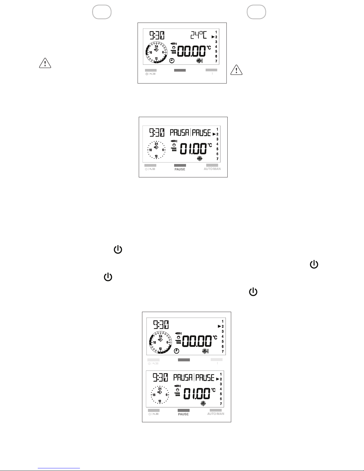
Premendo una volta il tasto
PAUSE, il display visualizza al
posto della temperatura ambiente quattro zeri.
Se entro 5 sec. dalla prima pressione del tasto
PAUSE non si effettua al-
cuna modica, il pannello
esce dalla funzione.
Premendo una seconda volta il tasto PAU-
SE è possibile iniziare ad impo-
stare le ore di interruzione. no
ad un massimo di 24 ore.
Il display si presenta come in
gura.
Ogni pressione del pulsante
PAUSE aumenta l’interruzione
di + 1 ora. Ogni pressione del
tasto AUTO-MAN diminuisce
l’interruzione di -1 ora.
Il programma “ PAUSA” si attiva subito
dopo l’impostazione delle ore di PAUSA e
termina al loro scadere.
Per uscire dalla funzione PAUSA, prima
della ne del tempo impostato, è neces-
sario premere il tasto “ “, dopo alcuni
secondi la scritta PAUSA scompare.
Ripremere il tasto “ ” per posizionarsi
sulla funzione desiderata.
VACANZE
Per attivare il programma è necessario posizionarsi in regime
invernale, e superare le 24 ore
di PAUSA nel seguente modo:
- dalla funzione inverno premere
il tasto PAUSE.
Il display visualizza al posto della temperatura ambiente quattro
zeri.
If you press the PAUSE button
If you press the PAUSE button
once, the display shows four
zeros in the room temperature
eld.
If, for 5 sec. from the
rst pressing you do not
make any modication,
the panel exits the function.
Another time, you can move on to set the
interruption time bands, which
can reach a maximum of 24
hours.
The display appears as in gure.
Each pressing of the PAUSE
button increases the interruption time band with 1 hour.
Each pressing of the AUTO/MAN button
decreases the interruption time band with
1 hour.
The “PAUSE” function enables right after
the PAUSE hours are set and disables
when they are over.
To exit the PAUSE function before the time
set is over, you have to press the “ “,
button; after some seconds the PAUSE
word disappears from the display.
Press again the “ ” button, to select
the function desired.
HOLIDAY
To enable the function, you
have to set the system in
winter mode and overtake
the 24 hours PAUSE in the
following way:
- in winter mode press the
PAUSE button.
The display shows four zeros in the room temperature
eld.
Page 15
15
IT EN
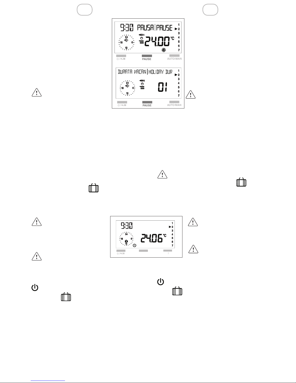
- premere ripetutamente PAU-
SE per iniziare ad impostare le
ore di interruzione.
Superate le 24 ore sul
display scomparirà la scritta
PAUSA.
Sul display appare DURATA
VACAN e il numero dei giorni
di assenza (ad esempio. 01)
Se non si effettua alcuna impostazione, dopo 3
sec. dalla visualizzazione
della scritta DURATA VACAN, il pannello esce automaticamente dalla programmazione.
Con il pulsante PAUSE è possibile incrementare la durata dei giorni di vacanza.
Con il pulsante AUTO/MAN è possibile decrementare la durata dei giorni di vacanza.
Per rendere operativa la programmazione
attendere circa 3 sec, il pannello memorizza i dati impostati.
Sul display compare “ ”.
Il pannello si posiziona nello stato spento.
Il programma “ VACANZE” si attiva imme-
diatamente dopo aver
impostato i valori.
Il termine della program-
mazione è sempre alle ore
24.00 dell’ultimo giorno
di programmazione.
Per interrompere anticipatamente la
funzione Vacanze, premere il tasto”
”.
Il simbolo “ ” si disattiva.
Selezionare il tipo di funzionamento desiderato
- press the PAUSE button re-
peteadly to start setting the interruption hours. Once the 24
hours are overtaken, the PAUSE word will disappear from
the display
The displayshows HOLIDAY
DUR and thenumber of days
of absence (forexample 01).
If you do not make any
setting, after 3 sec. from
displaying HOLIDAY
DUR, the panel automatically exits the programming
With the PAUSE button, you can increase
the number of vacation days.
With the AUTO/MAN button, you can decrease the number of vacation days.
To enable the function, wait 3 seconds, the panel memorizes the data set
On the display appears “ ”.
The panel enters off mode.
The “HOLIDAY” function will
enable right after the values are set.
The function always disables at 24.00 of the
last day scheduled.
If you want to disable the Holiday function
before it was scheduled to stop, press the”
” button.
The “ ” symbol disables.
Select the desired operating mode.
Page 16
IT EN
16
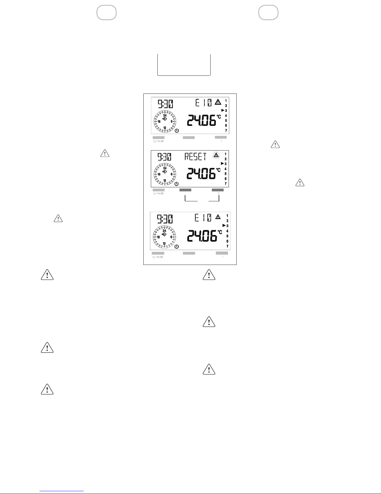
3.1.4 Unblocking function
Pressing simultaneously the buttons
you can reset the boiler after
a safety stop caused by a functioning fault.
During this function, the display shows the word RESET
and the “ “ ashing symbol.
After some moments, the word
RESET dissapears, the fault
code and the “ “, symbol
appear again for some seconds and then the boiler starts to
work normally.
If, after a safety stop, the boiler starts
over to work normally, the blocking is
due to a casual situation.
If the blockings repeat, you should
call the Service Center.
You can make up to 5 unblocking
attempts in 15 minutes, after that
press the OFF/Reset button directly
on the boiler.
For faults description, please refer to
chapter 5 “Faults”.
3.1.4 Funzione di sblocco
Premendo contemporaneamente i tasti
è possibile ripristinare il funzionamento della caldaia dopo un
arresto dovuto ad un’anomalia
di funzionamento.
Durante questa funzione il display visualizza la scritta RE-
SET e il simbolo “ “ lampeggiante.
Dopo alcuni istanti la scritta
RESET scompare, appaiono
nuovamente per alcuni secondi il codice anomalia e il simbo-
lo “ “, dopodiché la caldaia
riprende il normale funzionamento.
Se dopo un arresto di sicurezza, la
caldaia effettua la fase di accensione e riprende il regolare funzionamento, l’arresto è riconducibile ad
una situazione casuale.Il ripetersi di
blocchi suggerisce l’intervento del
Centro di Assistenza Tecnica.
È possibile effettuare no a 5 tentativi di sblocco in 15 minuti, dopo di ciò
agire sul tasto azzeramento direttamente in caldaia
Per la descrizione delle anomalie
fare riferimento al capito 5 Anomalie”.
PAUSE
AUTO I MAN
+
RESET
Page 17
17
IT EN
3.2 Funzioni avanzate
(coperchio aperto)
Aprendo il coperchio del pannello di controllo remoto si ha accesso diretto alle modalità di Controllo o Impostazione.
In questa modalità si possono modicare i
parametri sia del pannello di controllo remoto sia della caldaia e visualizzare i dati
dell’impianto.
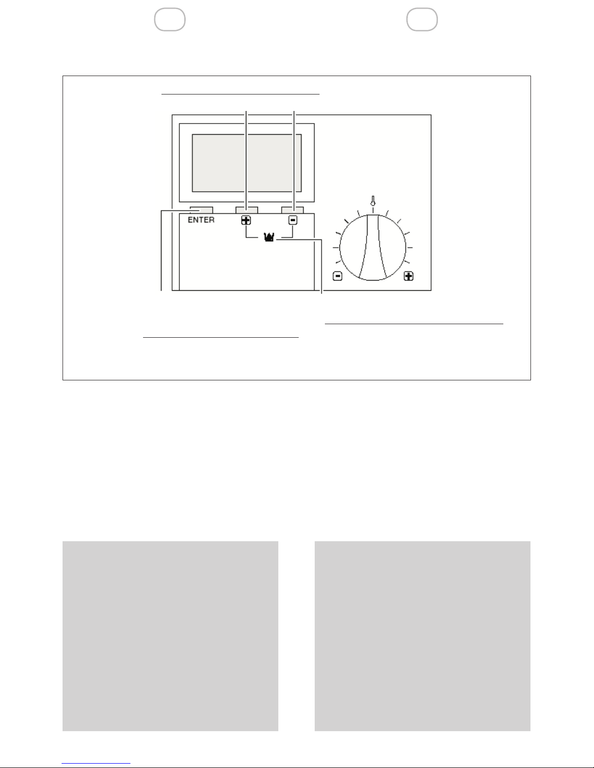
I tasti precedentemente descritti nella sezione coperchio chiuso, funzioni base, assumono le seguenti nuove funzioni
Pulsante ENTER consente la:
- selezione del menu
- selezione di un dato da modicare
- memorizzazione del nuovo valore
Pulsante “+”.
Consente la ricerca o la modica di un
valore impostato.
Pulsante “-”.
Consente la ricerca o la modica di un
valore impostato
By opening the dashboard cover, you can
access Control or Settings mode directly.
In this mode, you can adjust parameters
of either the remote control panel or the
boiler and see the installation data..
The buttons described previously in the
section “dashboard cover closed, basic
functions”, acquire the following new functions:
The ENTER button permits:
- selecting the menu
- selecting data to be modied
- memorizing the new value
The “+” button.
Permits searching or adjusting a value
set.
The “-” button.
Permits searching or adjusting a value
set
3.2 Advanced functions (dashboard cover open)
Ricerca o modica valore
Searches or modies value
Accesso ai menu di regolazione
Selezione di un dato da modicare
Conferma di un dato impostato
Access the adjusting menus
Selects data to be adjusted
Conrms that data is set
Caricamento impianto (premerecontem-
poraneamente i due tasti)
Fills up the installation (press bothbuttons
simultaneously)
Page 18
IT EN
18
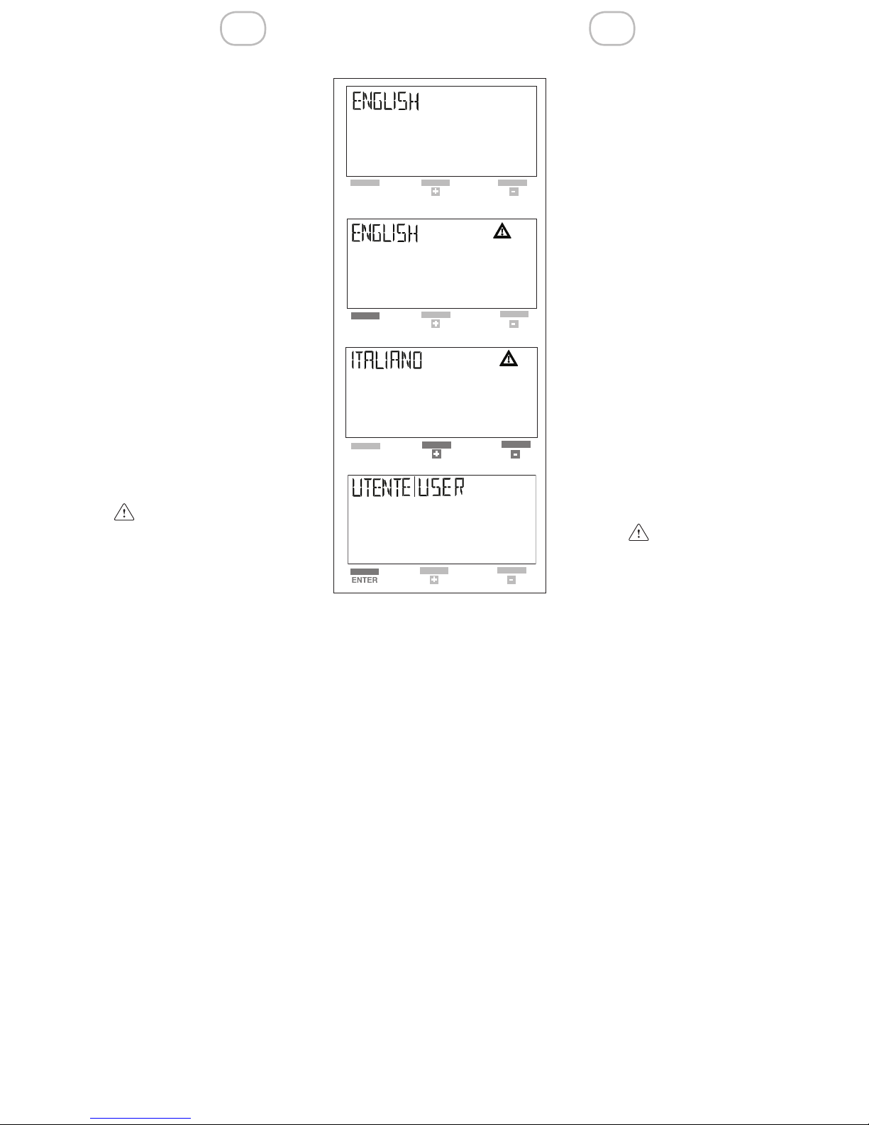
3.2.1 Impostazione della lingua
All’apertura del coperchio, solo
dopo ogni interruzione di alimentazione elettrica del pannello di controllo remoto, viene
visualizzata la lingua impostata.
La lingua impostata dal costruttore è l’ITALIANO.
Se la lingua visualizzata è quella desiderata, premere 2 volte
ENTER per proseguire.
Alle successive riaperture del
coperchio, il display visualizzerà la scritta “UTENTE”.
Se la lingua visualizzata non
corrisponde a quella desiderata
modicarla come segue:
- subito dopo l’apertura del coperchio, premere ENTER.
Sul display compaiono la lin-
gua corrente e il simbolo “
“.
- premere i tasti +/-, per sce-
gliere la lingua; di seguito
elenchiamo quelle disponibili:
ITALIANO
PORTUGUES
POLSKI
CROATIAN
CESKY
LIETUVISKAI
LATVIESU
SLOVENSKY
MAGYAR
DEUTSCH
ENGLISH
FRANCAIS
NEDERLANDS
ESPANOL
- confermare la scelta premendo ENTER.
3.2.1 Setting the language
By opening the dashboard
cover, only after each power
supply interruption of the remote control panel, the display shows the language set.
The language set by the manufacturer is ITALIAN.
If the language displayed corresponds to the one you desire, press ENTER twice to
move on.
If you reopen the dashboard cover successively, the
display will show the word
“USER”.
If the language displayed does
not correspond to the one you
desire, adjust it as follows:
- right after you open the dashboard, press ENTER.
The current language
and the “ “ symbol appear
on the display.
- press the +/- buttons to
select the language; here are
the ones available:
ITALIANO
PORTUGUES
POLSKI
CROATIAN
CESKY
LIETUVISKAI
LATVIESU
SLOVENSKY
MAGYAR
DEUTSCH
ENGLISH
FRANCAIS
NEDERLANDS
ESPANOL
- conrm the selection by pressing EN-
TER.
Page 19

19
IT EN
3.2.2 Selezione dei menu disponibili
Con il pulsante +/- è possibile
scorrere i menu disponibili, di
seguito elencati:
UTENTE: Impostazione di valori da parte dell’utente
VISUALIZZARE V i sualizzazione delle temperature e dei valori dell’impianto (in
questo menu non è possibile
modicare i valori visualizzati)
ORA-GIORNO: Impostazione
dell’ora e del giorno della settimana
PROGR-RISC: Impostazione
del programma di riscaldamento
TECNICO: Impostazione dei parametri (a
cura dell’installatore)
Per accedere ad un menu premere ENTER.
3.2.3 Modica dei dati preimpostati
Per modicare i valori impostati nei singoli
menu procedere come di seguito descritto:
- dopo aver scelto il MENU come sopra
descritto ed esservi entrati, scegliere il
parametro da modicare agendo con i
tasti + o -, quindi
- premere il pulsante ENTER per confermare la scelta. La comparsa sul display
del simbolo “ “ indica che è possibile
modicare il valore
- modicare il valore del parametro impo-
stato, agendo con i tasti + o -.
- premere il pulsante ENTER per confer-
mare la modica.
Il nuovo valore viene memorizzato e sul
display si spegne il simbolo “ “.
Se non si desidera memorizzare il nuovo
valore impostato, chiudere il coperchio di
servizio del pannello di controllo remoto
prima di premere ENTER.
3.2.2 Selecting the menus available
With the +/- buttons, you can
run through the menus available, presented below::
USER: Setting values, made
by user
DISPLAYING: Displaying temperatures and installation data
(in this menu it is not possible
to modify the values displayed)
TIME+DAY: Setting the hour
and day of the week
HTG-PROG Setting the heating schedule
EXPERT: Setting parameters,
made exclusively by the Service Center
Press ENTER to go to a menu.
3.2.3 Adjusting the preset data
To adjust the values set in each menu,
proceed as follows:
- after you selected and entered the
MENU in the way it is written above,
with the + or - buttons select the parameter to be adjusted, then
- press ENTER to conrm the selection.
The display of the “ “ symbol indicates that it is possible to modify the value
- adjust the value of the parameter set by
pressing the + or – button.
- press ENTER to conrm the modication.
The new value is memorized and the “ “
symbol dissappears from the display.
If you do not want the remote control panel
to memorize the new value set, close the
dashboard cover before pressing ENTER.
Page 20

IT EN
20
3.2.4 Descrizione dei menu
UTENTE
Nel menu utente è possibile impostare i
seguenti valori
- T-ACS 1 (35°C-60°C): La temperatura
desiderata dell’acqua calda sanitaria.
La temperatura desiderata per la pri-
ma fascia oraria in caso di programma acqua calda sanitaria (PROGRACS), vedi pag. 27
- T-ACS 2 (35°C-60°C): La temperatura
desiderata per la seconda fascia ora-
ria in caso di programma acqua calda
sanitaria (PROGR-ACS).
- T-ACS 3 (35°C-60°C):La temperatura
desiderata per la terza fascia oraria in
caso di programma acqua calda sanitaria (PROGR-ACS).
- TEMP-AMB 1 (5°C-40°C): La temperatura comfort in caso di funzionamento
manuale (vedi funzionamento manuale
- pag. 9)
La temperatura desiderata per la pri-
ma fascia oraria in caso di programmazione riscaldamento (PROGR-RISC), vedi pag. 22
- TEMP-AMB 2 (5°C-40°C °C): La temperatura desiderata per la seconda fa-
scia oraria.
- TEMP-AMB 3 (5°C-40°C): La temperatura desiderata per la terza fascia
oraria.
- T-RIDOTTA (5°C-40°C): L a
temperatura desiderata per il funzionamento notturno e per lo stato di PAUSA.
- INDIETRO: Consente di tornare al
menu UTENTE
Per variare i valori impostati seguire quanto descritto nel paragrafo “Modica dei valori impostati”
3.2.4 Description of menus
USER
In the user menu, you can set the following
values:
- T-DHW 1 (35°C-60°C): Desired domestic hot water temperature.
Desired temperature for the rst time
band in case of domestic hot water
schedule (HOTW-PROG), see page 27
- T-DHW 2 (35°C-60°C): Desired temperature for the second time band in
case of domestic hot water schedule
(HOTW-PROG).
- T-DHW 3 (35°C-60°C): Desired temperature for the third time band in case
of domestic hot water schedule (HOTW-PROG).
- T-ROOM DES 1 (5°C-40°C): Comfort
level temperature in case of manual
operating mode (see manual operating
mode – page 9)
Desired temperature for the rst time
band in case of heating schedule
(HTG-PROG), see page 22
- T-ROOM DES 2 (5°C-40°C °C): Desired temperature for the second time
band.
- T-ROOM DES 3(5°C-40°C):Desired
temperature for the third time band.
- T-REDUCED (5°C-40°C): D e sired temperature for night operating
mode and for PAUSE mode.
- RETURN: Permits returning to USER
menu
To change the values set, follow the indications in the paragraph “Adjusting the
values set”
Page 21

21
IT EN
VISUALIZZARE
Nel menu visualizzare è possibile scorrere
i seguenti valori che si riferiscono alle temperature lette istantaneamente:
- T ESTERNA: Si visualizza la temperatura esterna, solo se alla caldaia è stata
collegata una sonda esterna.
Premendo il tasto ENTER si visualizza
il valore massimo di temperatura ed
l’ora in cui è stato registrato.
Premendo + e - vengono visualizzati i
valori massimo e minimo e l’ora in cui
sono stati registrati.
Premendo ENTER si ritorna al menu
VISUALIZZARE.
- T-AMBIENTE: Visualizzazione della
temperatura ambiente [°C].
Premendo ENTER viene visualizzata
la temperatura ambiente impostata (TAMB1).
Premendo + e - vengono visualizzati i
valori massimo e minimo e l’ora in cui
sono stati registrati.
Premendo ENTER si ritorna al menu T-
AMBIENTE.
- T-ACS: Visualizzazione della temperatura in tempo reale dell’acqua calda
[°C].
Premendo ENTER viene visualizzata la
temperatura attuale desiderata.
Premendo ENTER si ritorna al menu T-
ACS.
- T-MANDATA: Visualizzazione della
temperatura di mandata della caldaia
[°C].
Premendo ENTER viene visualizzata la
temperatura calcolata.
Premendo ENTER si ritorna al menu T-
MANDATA.
- MODULAZIONE: visualizzazione della
potenza attuale della caldaia (%)
- TEMPO BRUC: Visualizzazione delle
ore di lavoro bruciatore .
Premendo ENTER viene azzerato il va-
lore memorizzato.
Premendo ENTER si ritorna al menu
TEMPO-BRUC.
DISPLAYING
In displaying menu, you can run through
the following values, which refer to instantaneously recorded temperatures:
- T-OUTSIDE: Displaying the external
temperature, only if an external probe
was connected to the boiler. By pressing ENTER, the display shows the
maximum temperature value and the
hour when it has been recorded. By
pressing + and – the display shows the
maximum and minimum values and the
hour when they have been recorded.
By pressing ENTER, you return to the
DISPLAYING menu.
- T-ROOM: Displaying the room temperature [°C]. By pressing ENTER, the display shows the room temperature set
(T-ROOM DES 1).
By pressing + and – the display shows
the maximum and minimum values and
the hour when they have been recorded. By pressing ENTER, you return to
the T-ROOM menu.
- T-DHW: Displaying domestic hot water
real-time temperature [°C].
By pressing ENTER, the display shows
the current desired temperature.
By pressing ENTER, you return to the
T-DHW menu.
- T-BOILER: displaying the boiler delivery temperature (°C). By pressing ENTER, the display shows the calculed
temperature. By pressing ENTER, you
return to the T-BOILER menu.
- MODULATION: Displaying the boiler
current working efciency [%].
- BURNER-TIME: Displaying the burner
working hours. By pressing ENTER,
you cancel the memorized value.
By pressing ENTER you return to the
BURNER-TIME menu.
Page 22

IT EN
22
- ACCENS BRUC: Visualizzazione del
numero di accensioni effettuate dal bruciatore caldaia.
Premendo ENTER viene azzerato il va-
lore memorizzato.
Premendo ENTER si ritorna al menu
Informazioni.
- PRESS ACQUA: visualizzazione della
pressione acqua in caldaia
- INDIETRO: Consente di tornare al
menu VISUALIZZARE.
ORA+GIORNO
Dal menu ORA+GIORNO effettuare le seguenti operazioni:
- Premere il pulsante ENTER.
Il display visualizza l’ora corrente e il
simbolo ” “.
- Con + e - impostare l’ora corretta.
Tenendo premuto il pulsante + o - i mi-
nuti scorrono a passi di 15 minuti: 15,
30, 45.
- Premere ENTER per confermare.
- Il display visualizzerà il giorno corrente
e il numero corrispondente:
lunedì 01
martedì 02
mercoledì 03
ecc.
- Con i pulsanti + o - impostare il giorno
desiderato.
- Premere ENTER per confermare.
- Il display si posiziona sul menu
ORA+GIORNO visualizzando le nuove
impostazioni memorizzate.
- BURNER-START: Displaying the burner start-ups number.
By pressing ENTER, you cancel the
memorized value.
By pressing ENTER, you return to the
Information menu.
- WATER-PRESS: Displaying the boiler
water pressure.
- RETURN: Permits returning to the DISPLAYING menu.
TIME+ DAY
In TIME+DAY menu, perform the following
operations:
- Press ENTER.
The display shows the current hour and
the ” “symbol.
- With + and – set the right hour.
By pressing continously + or - the mi-
nutes elapse by 15 minutes stages: 15,
30, 45.
- Press ENTER to conrm.
- The display shows the current day and
the corresponding number:
Monday 01
Tuesday 02
Wednesday 03
etc.
- With the + o – set the desired day
- Press ENTER to conrm.
- The display returns to the TIME+DAY
menu, displaying the new memorized
settings.
HTG-PROG
(heating schedule)
Permits programming three 24
hours operating time bands.
Each time band is assigned a
room temperature set in USER
menu (T-ROOM DES 1, 2, 3).
PROGR-RISC
(programmazione riscaldamento)
Permette di programmare tre
fasce orarie di funzionamento
nelle 24 ore. Ad ogni fascia oraria viene associata una temperatura ambiente impostata nel menu
UTENTE (TEMP-AMB 1, 2, 3).
Page 23

23
IT EN
Per impostare le fasce orarie procedere
come segue:
- posizionarsi su PROGR-RISC
- premere il pulsante ENTER, il display
visualizzerà il primo giorno della settimana
- con i tasti + e - selezionare uno dei programmi disponibili di seguito descritti:
· - Giornaliero: si possono programma-
re singolarmente i giorni della settimana. Il display visualizza i singoli giorni:
lunedì, martedì, mercoledì, ecc.
· - Feriale: si possono programmare
contemporaneamente i giorni della
settimana (da Lunedì al Venerdì) e di-
versicare il Sabato e la Domenica
· - Sab-Dom: si programmano solo il
Sabato e la Domenica
· - Settimanale: si possono program-
mare contemporaneamente tutti i
giorni della settimana (da Lunedì alla
Domenica)
Scegliere un programma, quindi premere
ENTER per confermare.
Il display per pochi secondi si presenta
come in gura A, dopodiché si presenta
come in gura B.
La programmazione delle fasce orarie incomincia sempre con un orario di accen-
sione (ON) contraddistinto dal simbolo
e termina con un orario di spegnimento
(OFF) col simbolo .
To set the time bands, proceed as follows:
- go to HTG-PROG
- press ENTER and the display will show
the rst day of the week
- with the + e – buttons select one of the
available programs, described below:
· - Daily: you can schedule each day
of the week separately. The display
will show each day: Monday, Tuesday,
Wednesday, etc.
· - Holiday: you can schedule week
days at the same time (Monday to Friday) and Saturday and Sunday differently
· - Sat-Sun: you schedule only Saturday
and Sunday
· - Weekly : you can schedule all the
days of the week at the same time
(Monday to Sunday)
Select a schedule, then press ENTER to
conrm.
For a few seconds, the display will appear
as in gure A, after that as in gure B.
The time bands programming phase always begins with a starting timetable
(ON), identied with the symbol and
nishes with an ending timetable (OFF),
identied with the symbol .
Page 24

IT EN
24
The 3 time bands are expressed on the
display by the following symbols:
1) ON OFF
2) ON OFF
3) ON OFF
Set the starting timetable (ON) by pressing the + and – buttons and the press
ENTER to conrm.
The display appears as in gure.
Set the ending timetable (OFF) by pressing the + and – buttons and the press
ENTER to conrm.
During the OFF phase, the boiler is
in night operating mode , and it will
switch on only if the temperature falls under the T-REDUCED value set
(see USER menu, paragraph 3.2.4).
Once you set down the ending timetable,
press ENTER.
The display appears as in gure.
Proceed the same way to set the subsequent time bands , .
After you nished programming, press the
+ or – button to go to RETURN and exit
the HTG-PROG menu.
Le 3 fasce orarie si presentano sul display
con i seguenti simboli:
1) ON OFF
2) ON OFF
3) ON OFF
Impostare l’orario di funzionamento (ON)
con i tasti + e -, quindi premere il pulsante
ENTER per confermare.
Il display si presenta come in gura.
Impostare l’orario di spegnimento (OFF)
con i tasti + e , quindi premere ENTER per
confermare.
Durante la fase di OFF la caldaia
è in regime notturno , quindi si
accenderà solo se la temperatura scende al di sotto del valore di
T-RIDOTTA impostato (vedi menu
UTENTE paragrafo 3.2.4).
Stabilito l’orario di spegnimento premere il
tasto ENTER.
Il display si presenta come in gura.
Procedere nello stesso modo per impostare le fasce successive , .
Al termine della programmazione premere i tasti + o - per posizionarsi sulla voce
INDIETRO e uscire dal menu PROGRACS.
Page 25

25
IT EN
To stop at any moment the time bands programming, close the cover of the panel.
The values set will not be memorized.
ou may exclude the heating schedule from
one or more time bands. To do so, proceed as follows:
- set a time band: example ON -
OFF as previously indicated
- press ENTER
- or the second time band overtake the
24 hours by pressing the + button.
The display shows segments instead of
the timetable, see the gure
- press ENTER to conrm.
By doing this operation, you excluded
the second time band from the heating schedule
- for the third time band overtake the 24
hours by pressing the + button
The display shows segments instead of
the timetable.
- press ENTER to conrm
By doing this operation, you excluded the
third time band from the heating schedule.
The boiler will operate according to the
time band set and will stay off the rest of
the time.
Per interrompere in qualsiasi momento la
procedura di programmazione delle fasce
orarie, chiudere il coperchio del pannello.
I valori impostati non vengono memorizzati.
è possibile escludere la programmazione
sanitario di una o più fasce. Per far ciò
operare come segue:
- impostare una fascia: esempio ON
- OFF come indicato in precedenza
- premere ENTER
- nella seconda fascia superare le 24 ore
con il tasto +.
Il display visualizza i segmenti al posto
dell’orario, vedi gura
- premere ENTER per confermare.
Con questa operazione abbiamo
escluso la seconda fascia del programma sanitario
- nella terza fascia le 24 ore con il tasto +.
Il display visualizza i segmenti al posto
dell’orario.
- premere ENTER per confermare
Con questa operazione abbiamo escluso
la terza fascia del programma sanitario.
La caldaia funzionerà secondo la fascia
oraria impostata e resterà spenta negli
altri periodi.
Ad ogni fascia oraria impostata nel menu
PROGR-ACS, viene automaticamente
associata la relativa temperatura acqua
sanitaria (T-ACS 1, 2, 3):
T-ACS1
T-ACS2
T-ACS3
The relative room temperature is automatically assigned to each time band set in the
HTG-PROG menu (T-ROOM DES 1, 2, 3):
T-ROOM DES1
T-ROOM DES2
T-ROOM DES3
Page 26

IT EN
26
Le temperature ambiente di default sono
settate a 20°C, ma è possibile modicarle come già spiegato nel paragrafo 3.2.4
“Descrizione dei menu” sezione dedicata
”UTENTE”.
Se le temperature ambiente sono state
personalizzate/modicate, i programmi si
assoceranno a questi nuovi valori.
Esempio di programmazione
Si desidera avere nell’arco della giornata
tre periodi di riscaldamento
- fascia 1: dalle ore 6.30 alle 8.30
temperatura desiderata 20°
- fascia 2: dalle 12.00 alle 15.00
temperatura desiderata 18°
- fascia 3: dalle 17.00 alle 23.00
temperatura desiderata 24°
Nel MENU PROGR-RISC impostare le fasce orarie.
Nel menu utente impostare le temperature
volute:
T-AMB1 20°C
T-AMB2 18°C
T-AMB3 24°C
L’andamento temperature/fasce orarie
sarà come indicato nel graco.
È possibile impostare temperature uguali
per fasce orarie diverse
es. T-AMB-1 = T-AMB-2
Non è possibile sovrapporre le fasce orarie.
The default room temperatures are set for
20°C, but you may adjust them, as already
explained in paragraph 3.2.4 “Description
of menus” “USER” dedicated section.
If the room temperatures were personali-
zed/modied, the programs are assigned
these new values.
EXAMPLE OF PROGRAMMING
We consider that you want to set three heating time bands in 24 hours.
- time band 1: from 6.30 to 8.30
desired temperature 20°
- time band 2: from 12.00 to 15.00
desired temperature 18°
- time band 3: from 17.00 to 23.00
desired temperature 24°
In HTG-PROG MENU set the time bands.
In USER MENU set the desired temperature:
T-ROOM DES1 20°C
T-ROOM DES2 18°C
T-ROOM DES3 24°C
The progress of temperature/time bands
will be as shown in the diagram.
You may set even temperatures for different time bands
Eg. T-ROOM DES-1 = T-ROOM DES-2
It is not possible to overlay the time bands.
fasce orarie/time bands
temperature/temperatures
°C
T-RIDOTTA
T-REDUCED
T-AMB2
T-ROOM DES 2
T-AMB1
T-ROOM DES 1
T-AMB3
T-ROOM DES 3
15
16
17
18
19
20
21
22
23
24
6.30 8.30
12.00 15.00
17.00 23.00
ON OFF ON OFF ON OFF
ora
hour
fascia 1
time band 1
fascia 2
time band 2
fascia 3
time band 3
Page 27

27
IT EN
PROGR-ACS
(programma acqua calda sanitaria)
Permette di programmare tre
fasce orarie di funzionamento
nelle 24 ore.
Ad ogni fascia oraria viene associata una temperatura sanitaria impostata nel menu UTENTE (TEMP-ACS 1, 2, 3).
Questa funzione è attiva
solo in caso di caldaie con bollitore.
Se il bollitore è munito di sonda, è
possibile impostare la temperatura
desiderata, in caso di bollitore con
termostato la temperatura dell’acqua deve essere impostata sul bollitore stesso.
Per impostare le fasce orarie proce-
dere come segue:
- posizionarsi su PROGR-ACS
- premere il pulsante ENTER, il display
visualizzerà il primo giorno della settimana
- con i tasti + e - selezionare uno dei programmi disponibili di seguito descritti:
· Giornaliero: si possono programmare
singolarmente i giorni della settimana.
Il display visualizza i singoli giorni: lunedì, martedì, mercoledì, ecc.
· Feriale: si possono programmare contemporaneamente i giorni della settimana (da Lunedì al Venerdì) e diversicare il Sabato e la Domenica
· Sab-Dom: si programmano solo il Sabato e la Domenica
· Settimanale: si possono programmare
contemporaneamente tutti i giorni della
settimana (da Lunedì alla Domenica)
Scegliere un programma, quindi premere
ENTER per confermare.
HOTW-PROG
(domestic hot water schedule)
Permits programming three
operating time bands during
the 24 hours.
Each time band is assigned a
sanitary temperature set in the
USER menu (T-DHW 1, 2, 3).
This function is enabled only
for boilers with water tanks.
If the water tank is equipped with
probe, you can set the desired tem-
perature; for boilers with thermostat,
you have to set the water temperature directly on the boiler.
To set the time bands, proceed as
follows:
- go to HOTW-PROG
- press ENTER, the display will show the
rst day of the week
- with the + e – buttons select one of the
available schedules described below:
· Daily: you can schedule each day of
the week separately. The display will
show each day: Monday, Tuesday,
Wednesday, etc
· Holiday:you can schedule week days
at the same time (Monday to Friday)
and Saturday and Sunday differently
· Sab-Dom: you schedule only Saturday
and Sunday
· Weekly: you can schedule all the days
of the week at the same time (Monday
to Sunday)
Select a schedule, then press ENTER to
conrm
Page 28

IT EN
28
Il display per pochi secondi si presenta
come in gura A, dopodiché si presenta
come in gura B.
La programmazione delle fasce orarie incomincia sempre con un orario di accensione (ON) contraddistinto dal simbolo
e termina con un orario di spegnimento
(OFF) col simbolo .
Le 3 fasce orarie si presentano sul display
con i seguenti simboli:
1) ON OFF
2) ON OFF
3) ON OFF
Impostare l’orario di funzionamento (ON)
con i tasti + e -, quindi premere il pulsante
ENTER per confermare.
Il display si presenta come in gura.
Impostare l’orario di spegnimento (OFF)
con i tasti + e , quindi premere ENTER per
confermare.
Durante la fase di OFF viene inibita
la preparazione dell’acqua calda sa-
nitaria in caldaia.
Stabilito l’orario di spegnimento premere il
tasto ENTER.
Il display si presenta come in gura.
Procedere nello stesso modo per impostare le fasce successive , .
For a few seconds, the display will appear
as in gure A, after that as in gure B.
The time bands programming phase always begins with a starting timetable
(ON), identied with the symbol and
nishes with an ending timetable (OFF),
identied with the symbol . .
The 3 time bands are expressed on the
display by the following symbols:
1) ON OFF
2) ON OFF
3) ON OFF
Set the starting timetable (ON) by pressing
the + and – buttons and the press ENTER
to conrm.
The display appears as in gure.
Set the ending timetable (OFF) by pressing the + and – buttons and the press
ENTER to conrm.
During the OFF phase, thepreparation of domestic hotwater is stopped.
Once you set down the ending time-
table, press ENTER.
The display appears as in gure.
Proceed the same way to set the subsequent time bands , .
Page 29

29
IT EN
Al termine della programmazione premere
i tasti + o - per posizionarsi sulla voce INDIETRO e uscire dal menu PROGR-ACS.
Per interrompere in qualsiasi momento la
procedura di programmazione delle fasce
orarie, chiudere il coperchio del pannello.
I valori impostati non vengono memorizzati.
È possibile escludere la programmazione
sanitario di una o più fasce. Per far ciò
operare come segue:
- impostare una fascia: esempio
ON - OFF come indicato in precedenza
- premere ENTER
- nella seconda fascia superare le 24 ore
con il tasto +.
Il display visualizza i segmenti al posto
dell’orario, vedi gura
- premere ENTER per confermare.
Con questa operazione abbiamo
escluso la seconda fascia del programma sanitario
- nella terza fascia le 24 ore con il tasto +.
Il display visualizza i segmenti al posto
dell’orario.
- premere ENTER per confermare
Con questa operazione abbiamo escluso
la terza fascia del programma sanitario.
La caldaia funzionerà secondo la fascia
oraria impostata e resterà spenta negli
altri periodi.
Ad ogni fascia oraria impostata nel menu
PROGR-ACS, viene automaticamente
associata la relativa temperatura acqua
sanitaria (T-ACS 1, 2, 3):
After you nished programming, press the
+ or – button to go to RETURN and exit
the HOTW-PROG menu.
To stop at any moment the time bands programming, close the cover of the panel.
The values set will not be memorized.
ou may exclude the heating schedule from
one or more time bands. To do so, proceed as follows:
- set a time band: example ON OFF as previously indicated
- press ENTER
- for the second time band overtake the
24 hours by pressing the + button.
The display shows segments instead of
the timetable, see the gure
- press ENTER to conrm.
By doing this operation, you excluded
the second time band from the heating
schedule
- for the third time band overtake the 24
hours by pressing the + button
The display shows segments instead of
the timetable.
- press ENTER to conrm
By doing this operation, you excluded the
third time band from the heating schedule.
The boiler will operate according to the
time band set and will stay off the rest of
the time.
The relative domestic hot watertemperature is automaticallyassigned to
each time band setin the HOTW-PROG
menu (T-DHW 1, 2, 3):
Page 30

IT EN
30
T-ACS1
T-ACS2
T-ACS3
Le temperature sanitarie di default sono
settate a 50°C, ma è possibile modicarle come già spiegato nel paragrafo 3.2.4
“Descrizione dei menu” sezione dedicata
”UTENTE”. Se le temperature sanitarie
sono state personalizzate/modicate, i
programmi si assoceranno a questi nuovi
valori.
ESEMPIO DI PROGRAMMAZIONE
Si desidera avere nell’arco della giornata tre
periodi di preparazione dell’acqua sanitaria
- fascia 1: dalle ore 6.30 alle 8.30
temperatura desiderata 45°
- fascia 2: dalle 12.00 alle 15.00
temperatura desiderata 50°
- fascia 3: dalle 17.00 alle 23.00
temperatura desiderata 48°
Nel MENU PROGR-ACS impostare le fasce orarie.
Nel MENU UTENTE impostare le temperature volute:
T-ACS1 45°C
T-ACS2 50°C
T-ACS3 48°C
L’andamento temperature/fasce orarie
sarà come indicato nel graco.
È possibile impostare temperature uguali
per fasce orarie diverse
es. T-ACS-1 = T-ACS-2
Non è possibile sovrapporre le fasce orarie.
T-DHW1
T-DHW2
T-DHW3
The default domestic hot watertemperatures are set for 50°C, butyou may
adjust them as alreadyexplained in paragraph 3.2.4“Description of menus”,
“USER”dedicated section. If the domestic
hotwater temperatures werepersonalized/
modied, the programsare assigned these
new values.
EXAMPLE OF PROGRAMMING
We consider that you want to set three heating time bands in 24 hours.
- time band 1 from 6.30 to 8.30
desired temperature 45°
- time band 2 from 12.00 to 15.00
desired temperature 50°
- time band 3 from 17.00 to 23.00
desired temperature 48°
In PROGR-RISC MENU set the time bands.
In USER MENU set the desired temperature:
T-DHW1 45°C
T-DHW2 50°C
T-DHW3 48°C
The progress of temperature/time bands
will be as shown in the diagram.
You may set even temperatures for different time bands
Eg. T-DHW-1 = T-DHW-2
It is not possible to overlay the time bands.
T-ACS2
T-DHW2
T-ACS1
T-DHW1
T-ACS3
T-DHW3
34
36
38
40
42
44
46
48
50
6.30 8.30
12.00 15.00
17.00 23.00
ON OFF ON OFF ON OFF
fasce orarie/time bands
temperature/temperatures
°C
ora/
hour
fascia 1
time band 1
fascia 2
time band 2
fascia 3
time band 3
Page 31

31
IT EN
4 SPEGNIMENTO
Spegnimento per brevi periodi
In caso di brevi assenze premere il tasto “ ” sul pannello
remoto - con coperchio chiuso
- per spegnere la caldaia.
Il display si presenterà come in
gura.
Il pannello di controllo remoto
mantiene tutte le impostazioni
memorizzate.
In questo modo lasciando attive l’alimentazione elettrica e l’alimentazione del combustibile, la caldaia è protetta dai sistemi:
- Antigelo di caldaia: quando la temperatura dell’acqua di caldaia scende al di
sotto dei valori di sicurezza si attiva il
circolatore e il bruciatore alla minima
potenza per riportare la temperatura
dell’acqua a valori di sicurezza (35 °C).
- Antigelo da REC (vedi libretto installatore).
- Antibloccaggio circolatore: un ciclo di
funzionamento si attiva ogni 24 h.
Spegnimento per lunghi
periodi
In caso di assenze prolungate
premere, sul pannello di control-
lo remoto, il tasto“ ”per spegnere la caldaia.
Posizionare l’interruttore generale dell’impianto su “spento”.
Chiudere quindi il rubinetto del
gas posto sotto la caldaia, ruotandolo in
senso orario.
In questo caso i sistemi antigelo e antibloccaggio sono disattivati.
Svuotare l’impianto termico oppure proteggerlo adeguatamente con liquido anticongelante di buona marca.
Svuotare l’impianto sanitario.
4 SWITCHING OFF
Switching off for short periods
In the event of short periods of
absence, press the “ ” button
on the remote control panel –
with the dashboard cover closed
– to switch off the boiler.
The display will appear as in gure.
The remote control panel keeps
all the settings memorized.
This way, leaving the power supply and
the gas supply on, the boiler is protected
by the systems:
- Anti-freeze: when the water temperature in the boiler falls below safety values, the circulation pump enables and
the burner starts at minimum power, in
order to restore the water temperature
to safety values (35 °C).
- Anti-freeze from remote controlpanel
(see installer’s manual).
- Circulation pump anti-blocking: an
operating cycle starts at every 24 h.
Switching off for long periods
In case of long periods of absence, press the“ ”button
on the remote control panel –
with dashboard cover closed to switch off the boiler.
Turn the general system
switch to “OFF”.
Then, close the gas tap placed under the
boiler, by turning it clockwise. In this case,
the anti-freeze and anti-blocking systems
are disabled.
Drain the heatingsystem or suitablyprotect
it with a good make ofanti-freeze.Drain the
hot water system.
rubinetto gas
chiuso
gas tap closed
Page 32

IT EN
32
5 ANOMALIE
Quando si presenta un’anomalia di funzionamento, sul
display si visualizzeranno un
codice lampeggiante e il simbolo ” “.
Per ripristinare il funzionamento
della caldaia dopo un’anomalia,
premere contemporaneamente
i tasti PAUSE e AUTO MAN per
circa 3 secondi, vedi paragrafo
“3.1.4 Funzioni di sblocco”.
Durante questa operazione il
display visualizza la scritta RESET ed il simbolo ” “ lampeggiante (vedi paragrafo 3.1.4
Funzioni di sblocco).
Se dopo un arresto di sicurezza, la caldaia effettua la fase di accensione
e riprende il regolare funzionamento, l’arresto è riconducibile
ad una situazione casuale.
Il ripetersi di blocchi suggerisce l’in-
tervento del Centro di Assistenza Tecnica.
ANOMALIA E20
Nel caso sul display venga visualizzato
l’allarme E20.
Se la procedura di reset si conclude positivamente, sul display
scompare il codice E20.
Se l’anomalia permane, premere il tasto per spegnere la
caldaia e chiamare il Centro di
Assistenza Tecnica.
ANOMALIA E41
Nel caso in cui sul display venga
visualizzata la scritta RICH RIEMP, per
mancanza acqua è possibile attivare la
procedura di riempimento nel
seguente modo:
MODELLI C.S.I.:
- aprire il coperchio
- premere contemporaneamente
i tasti + e - per alcuni secondi.
- sul display compare la scritta
RIEMPIMENTO.
Se la procedura di riempimento
automatico si conclude positivamente, sul
display scompare la scritta RICH RIEMP.
Se la scritta permane e non viene effettuato
un riempimento si potrebbe trasformare
prima in anomalia E41 e poi in anomalia
definitiva E40.
5 FAULTS
When a functioning fault occurs, the display shows a
ashing fault code and the ”
“ symbol.
To reset the boiler after a fault
occurred, press the PAUSE and
AUTO MAN buttons simultaneously for about 3 seconds,
see paragraph “3.1.4 Unblo-
cking function”.
During this operation, the display shows the word RESET
and the ” “ ashing symbol
(see paragraph 3.1.4 Unblo-
cking function).
If, after a safety stop, the boiler
starts over to operate normally, the
blocking is due to a casual situation.
If the blockings repeat, you should
call the Service Center.
FAULT E20
Whether the E20 code appears
on the display.
If resetting succeeds, the E20
code dissapears from the display. If the fault persists, press
the button to switch off the boiler and call the Service Center.
FAULT E41
Should the wording FILL REQ
appear on the display for lack
of water, the filling procedure
can be activated as follows:
C.S.I. MODELS:
- open the cover
- press both + and – buttons
together for a few seconds.
- the wording FILL UP appears on the display.
If the automatic filling procedure concludes successfully, the wording FILL REQ
disappears from the display.
PAUSE
AUTO I MAN
+
RESET
Page 33

33
IT EN
DESCRIZIONE ANOMALIA cod. anom.
EXCLUSIVE - EXCLUSIVE SINTHESI
BLOCCO MANCANZA FIAMMA (D) E 10
FIAMMA PARASSITA (D) E 11
TERMOSTATO LIMITE (D) E 20
TERMOSTATO BRUCIATORE (D) (MIX C.S.I. - R.S.I. - SINTHESI C.S.I.) E 21
TERMOSTATO FUMI (D) (C.A.I. - R.A.I.) E 22
SCARICO FUMI O PRESSOSTATO ARIA (inizio ciclo) (D) (MIX C.S.I.-R.S.I.-SINTHE-
SI)
E 30
SCARICO FUMI O PRESSOSTATO ARIA (in ciclo) (T) (MIX C.S.I.-R.S.I.-SINTHESI) E 31
PRESSIONE IMPIANTO INSUFFICIENTE (D) E 40
PRESSIONE IMPIANTO INSUFFICIENTE (T) E 41
TRASDUTTORE PRESSIONE ACQUA (D) E 42
SCHEDA ELETTRONICA (D) E 50-59
SONDA SANITARIO 1 (T) (R.A.I.-R.S.I. solo con bollitore con sonda) E 60
ANOMALIA CICLO MINIACCUMULO (T) (MICROCAI - MICROMIX) E 65
SONDA PRIMARIO (T) E 71
TERMOSTATO BASSA TEMPERATURA (T) E 77
PRESENZA CONDENSA (D) (SINTHESI C.S.I.) E 92
PRESENZA CONDENSA (T) (SINTHESI C.S.I.) E 93
SENSORE CONDENSA CIRCUITO APERTO/MANCANZA
COLLEGAMENTO SCHEDA BE01 (D) (SINTHESI C.S.I.)
E 94
SENSORE CONDENSA O CIRCUITO APERTO (T) (SINTHESI C.S.I.) E 95
KOMPAKT
BLOCCO MANCANZA FIAMMA (D) E 10
FIAMMA PARASSITA (D) E 11
TERMOSTATO LIMITE (D) E 20
TERMOSTATO BRUCIATORE (C.S.I.) E 21
TERMOSTATO FUMI (C.A.I.) E 22
IT
Anomalia E40: sbloccare la
caldaia premendo contemporaneamente i tasti PAUSE e AUTO
MAN per circa 3 secondi e procedere al riempimento dell’impianto
come sopra descritto.
Il ripetersi di blocchi suggerisce
l’intervento del Centro di Assistenza Tecnica.
MODELLI R.S.I.
- premere il tasto “ ” per spegnere la
caldaia
- chiedere l’intervento del Centro di Assistenza Tecnica.
ANOMALIA “SFIATO”
(solo per modelli Exclusive Boiler Green)
La visualizzazione di “SFIATO” indica che
la caldaia sta effettuando il ciclo di sato
automatico della durata di circa 2 minuti.
Premendo contemporaneamente i tasti
PAUSE e AUTO MAN per circa 3 secondi
è possibile interrompere il ciclo.
If the wording remains and filling has not been activated first
it could be transformed into
error E41 then into definitive
error E40.
Error E40: un-lock the boiler
by pressing both the PAUSE
and AUTO MAN buttons together for about 3 seconds then carry on with
filling the system as described above.
Best to call the servicing centre with repeated lock-outs.
R.S.I. MODELS
- press the button to switch off the boiler
- call the servicing centre for help.
FAULT VENT
(only for Exclusive Boiler Green models)
The display of “VENT” indicates that the
boiler is making the automatic air discharge cycle, which takes about 2 minutes. By
pressing the PAUSE and AUTO MAN buttons simultaneously for about 3 seconds,
you can interrupt the cycle.
Page 34

34
SCARICO FUMI O PRESSOSTATO ARIA (inizio ciclo) (D) (MIX C.S.I.) E 30
SCARICO FUMI O PRESSOSTATO ARIA (in ciclo) (T) (MIX C.S.I) E 31
PRESSIONE IMPIANTO INSUFFICIENTE (D) E 40
PRESSIONE IMPIANTO INSUFFICIENTE (T) E 41
TRASDUTTORE PRESSIONE ACQUA (D) E 42
SCHEDA ELETTRONICA (D) E 50-59
SONDA SANITARIO 1 (T) E 60
SONDA PRIMARIO (T) E 71
TERMOSTATO BASSA TEMPERATURA (T) E 77
EXCLUSIVE GREEN - MICROGREEN - BOILER GREEN
BLOCCO MANCANZA FIAMMA (D) E 10
FIAMMA PARASSITA (T) E 11
RITENTATIVO ACCENSIONE (T) E 12
PRESSIONE MINIMA INGRESSO GAS (T) E 13
PRESSIONE MINIMA INGRESSO GAS (D) E 14
FIAMMA PRESENTE SENZA RAGIONE IN STAND-BY (D) E 15
TERMOSTATO LIMITE/TERMOSTATO BRUCIATORE E 20
SONDA FUMI CORTO CIRCUITO (D) E 21
SONDA FUMI MASSIMA TEMPERATURA (D) E 22
SONDA MANDATA TEMPERATURA LIMITE (D) E 24
SONDA MANDATA TEMPERATURA LIMITE (T) E 25
SONDA RITORNO TEMPERATURA LIMITE (D) E 26
SONDA RITORNO TEMPERATURA LIMITE (T) E 27
DIFFERENZIALE SONDA RITORNO-MANDATA (D) E 28
SONDA FUMI CIRCUITO APERTO (D) E 29
SCARICO FUMI O PRESSOSTATO ARIA (inizio ciclo) (D) E 30
SCARICO FUMI O PRESSOSTATO ARIA (in ciclo) (T) E 31
VENTILATORE IN CICLO (basso numero di giri) (D) E 33
VENTILATORE (inizio ciclo) (D) E 34
VENTILATORE (ne ciclo) (T) E 35
SCARICO FUMI O PRESSOSTATO ARIA (in ciclo) (T) E 36
VENTILATORE IN CICLO (alto numero di giri) (D) E 37
SCARICO FUMI O PRESSOSTATO ARIA (in ciclo) (D) E 38
PRESSIONE IMPIANTO INSUFFICIENTE (D) E 40
PRESSIONE IMPIANTO INSUFFICIENTE (T) E 41
TRASDUTTORE PRESSIONE ACQUA (D) E 42
CICLO DI SFIATO (BOILER GREEN) E 43
SCHEDA ELETTRONICA (D) E 50-59
SONDA SANITARIO 1 (GREEN R.S.I. solo con bollitore con sonda) (T) E 60
ANOMALIA CICLO MINIACCUMULO (MICROGREEN) (T) E 65
SONDA PRIMARIO CORTO CIRCUITO/APERTA (D) E 70
SONDA MANDATA SOVRATEMPERATURA (T) E 71
SONDA RITORNO CORTO CIRCUITO/APERTA (D) E 72
TERMOSTATO BASSA TEMPERATURA (T) E 77
DIFFERENZIALE MANDATA/RITORNO (T) E 78
DIFFERENZIALE MANDATA/RITORNO (D) E 79
ANOMALIA DI SISTEMA (D) E 80
ANOMALIA DI SISTEMA (T) E 81
ANOMALIA DI SISTEMA (D) E 82
ANOMALIA DI SISTEMA (T) E 83
CONDENSA O SENSORE DI CONDENSA (D) E 92
CONDENSA O SENSORE DI CONDENSA (T) E93
SENSORE DI CONDENSA O CIRCUITO APERTO (D) E 94
SENSORE DI CONDENSA O CIRCUITO APERTO (T) E 95
D = denitivo T = temporaneo
Page 35

35
EN
FAULT DESCRIPTION fault code
EXCLUSIVE - EXCLUSIVE SINTHESI
FLAME FAILURE BLOCK (D) E 10
PARASITE FLAME (D) E 11
LIMIT THERMOSTAT (D) E 20
BURNER THERMOSTAT (D) (MIX C.S.I. - R.S.I. - SINTHESI C.S.I.) E 21
FUMES THERMOSTAT (D) (C.A.I. - R.A.I.) E 22
FUMES OUTLET OR AIR PRESSURE SWITCH (cycle start) (D) (MIX C.S.I.-R.S.I.-SINTHESI)
E 30
FUMES OUTLET OR AIR PRESSURE SWITCH (in cycle) (T) (MIX C.S.I.-R.S.I.-SINTHESI)
E 31
INSUFFICIENT INSTALLATION PRESSURE (D) E 40
INSUFFICIENT INSTALLATION PRESSURE (T) E 41
WATER PRESSURE TRANSDUCER (D) E 42
ELECTRONIC BOARD (D) E 50-59
SANITARY PROBE 1 (T) (R.A.I.-R.S.I. only with water tank with probe) E 60
MINITANK CYCLE FAULT (T) (MICROCAI - MICROMIX) E 65
PRIMARY PROBE (T)) E 71
LOW TEMPERATURE THERMOSTAT (T) E 77
CONDENSATION PRESENT (D) (SINTHESI C.S.I.) E 92
CONDENSATION PRESENT (T) (SINTHESI C.S.I.) E 93
OPEN CIRCUIT CONDENSATION SENSOR/MISSING CONNECTION
WITH BE01 ELECTRONIC BOARD (D) (SINTHESI C.S.I.)
E 94
CONDENSATION SENSOR OR OPEN CIRCUIT (T) (SINTHESI C.S.I.) E 95
KOMPAKT
FLAME FAILURE BLOCK (D) E 10
PARASITE FLAME (D) E 11
LIMIT THERMOSTAT (D) E 20
BURNER THERMOSTAT (C.S.I.) E 21
FUMES THERMOSTATI (C.A.I.) E 22
FUMES OUTLET OR AIR PRESSURE SWITCH (cycle start) (D) (MIX C.S.I.) E 30
FUMES OUTLET OR AIR PRESSURE SWITCH (in cycle) (T) (MIX C.S.I) E 31
INSUFFICIENT INSTALLATION PRESSURE (D) E 40
INSUFFICIENT INSTALLATION PRESSURE (T) E 41
WATER PRESSURE TRANSDUCER (D) E 42
ELECTRONIC BOARD (D) E 50-59
SANITARY PROBE 1 (T) E 60
PRIMARY PROBE (T) E 71
LOW TEMPERATURE THERMOSTAT (T) E 77
EXCLUSIVE GREEN - MICROGREEN - BOILER GREEN
FLAME FAILURE BLOCK (D) E 10
PARASITE FLAME (T) E 11
RE-ATTEMPT IN PROGRESS (T) E 12
MINIMUM GAS INPUT PRESSURE (T) E 13
MINIMUM GAS INPUT PRESSURE (D) E 14
FLAME PRESENT IN STAND-BY FOR NO REASON (D) E 15
LIMIT THERMOSTAT/BURNER THERMOSTAT E 20
SHORT CIRCUIT FUMES PROBE (D) E 21
MAXIMUM TEMPERATURE FUMES PROBE (D) E 22
LIMIT TEMPERATURE DELIVERY PROBE (D) E 24
LIMIT TEMPERATURE DELIVERY PROBE (T) E 25
LIMIT TEMPERATURE RETURN PROBE (D) E 26
LIMIT TEMPERATURE RETURN PROBE (T) E 27
DIFFERENTIAL DELIVERY-RETURN PROBE (D) E 28
FUMES PROBE OPEN CIRCUIT (D) E 29
FUMES OUTLET OR AIR PRESSURE SWITCH (cycle start)(D) E 30
FUMES OUTLET OR AIR PRESSURE SWITCH (in cycle) (T) E 31
VENTILATOR IN CYCLE (low number of rotations) (D) E 33
VENTILATOR (cycle start) (D) E 34
Page 36

IT EN
36
VENTILATOR (cycle end) (T) E 35
FUMES OUTLET OR AIR PRESSURE SWITCH (in cycle) (T) E 36
VENTILATOR IN CYCLE (high number of rotations) (D) E 37
FUMES OUTLET OR AIR PRESSURE SWITCH (in c (D) E 38
INSUFFICIENT INSTALLATION PRESSURE (D) E 40
INSUFFICIENT INSTALLATION PRESSURE (T) E 41
WATER PRESSURE TRANSDUCER (D) E 42
AIR DISCHARGE CYCLE (BOILER GREEN) E 43
ELECTRONIC BOARD (D) E 50-59
SANITARY PROBE 1 (GREEN R.S.I. only with water tank with probe) (T) E 60
MINITANK CYCLE FAULT (MICROGREEN) (T) E 65
SHORT CIRCUIT/OPEN PRIMARY PROBE (D) E 70
OVER-TEMPERATURE DELIVERY PROBE (T) E 71
SHORT CIRCUIT/OPEN RETURN PROBE (D) E 72
LOW TEMPERATURE THERMOSTAT (T) E 77
DELIVERY/RETURN DIFFERENTIAL (T) E 78
DELIVERY/RETURN DIFFERENTIAL (D) E 79
SYSTEM FAULT (D) E 80
SYSTEM FAULT (T) E 81
SYSTEM FAULT (D) E 82
SYSTEM FAULT (T) E 83
CONDENSATE OR CONDENSATION SENSOR (D) E 92
CONDENSATE OR CONDENSATION SENSOR (T) E93
CONDENSATION SENSOR OR OPEN CIRCUIT (D) E 94
CONDENSATION SENSOR OR OPEN CIRCUIT (T) E 95
D = denitive T = temporary
6 VARIE
Il pannello di controllo remoto è alimentato elettricamente dalla caldaia.In caso di
interruzione della linea di comunicazione
tra pannello remoto e caldaia o in mancanza di alimentazione elettrica, il display
digitale si spegne totalmente.Il pannello è
dotato di una memoria in-terna a lunga durata che ha lo scopo dimantenere memorizzati tutti i program-mi impostati, tranne
l’impostazione dell’ora e del giorno.
6 MISCELLANEOUS
The remote control panel is supplied withelectric power by the boiler. If there is a bre-
akdown in thecommunication line between
the remote panel and the boiler or there is
no powersupply, the digital display shuts
offcompletely. The panel is equipped with
a long durationinternal memory with the
purpose ofmemorizing all the schedules
set, excepthour and day settings.
Page 37

37
PL
Szanowny Kliencie,
Beretta zawsze stara się spełniać wymogi swoich Klientów wykorzystując przy produkcji
swoich urządzeń całą swą wiedzę i gromadzone przez lata doświadczenie. Celem niniejszej
publikacji jest zapoznanie użytkowników z zasadami działania naszego nowego programatora oraz zapewnienie pełnego zadowolenia z jego funkcjonalności. Należy dokładnie
zapoznać się z instrukcjami podanymi w niniejszym dokumencie, co umożliwi poprawną
eksploatację i konserwację urządzenia. Po przeczytaniu należy zachować niniejszą
instrukcję w bezpiecznym miejscu, ponieważ może być ona przydatna w przyszłości.
Page 38

PL
38
W niektórych częściach niniejszej instrukcji stosowane są następujące symbole:
UWAGA = dotyczy czynności, które muszą być wykonywane przez odpowiednio
wyszkolone osoby z zachowaniem ostrożności
ZABRONIONE = dotyczy czynności, których NIE NALEŻY wykonywać
SPIS TREŚCI
1 INFORMACJE OGÓLNE str. 42
2 AKTYWACJA URZĄDZENIA str. 44
3 KORZYSTANIE Z PANELU STEROWNICZEGO str. 46
3.1 Funkcje podstawowe (zamknięta klapka płyty) str. 46
3.1.1 Wybór trybu roboczego str. 47
Tryb letni str. 47
Tryb zimowy str. 47
Ręczny tryb roboczy TERMOSTAT POKOJOWY str. 47
Nocny tryb roboczy str. 48
Automatyczny tryb roboczy PROGRAMOWANY
TERMOSTAT POKOJOWY str. 48
3.1.2 Pokrętło regulacji temperatury w pomieszczeniu str. 49
3.1.3 Przerywanie harmonogramu ogrzewania str. 49
Przerwa str. 49
Nieobecność str. 50
3.1.4 Funkcja odblokowywania systemu str. 52
3.2 Funkcje zaawansowane (otwarta klapka płyty) str. 53
3.2.1 Wybór języka str. 54
3.2.2 Wybór dostępnych menu str. 55
3.2.3 Regulacja zaprogramowanych danych str. 55
3.2.4 Opis menu str. 56
UŻYTKOWNIK str. 56
WSKAZANIE str. 56
CZAS + DATA str. 58
PROG GRZ (programowanie C.O.) str. 59
PROGR CWU
(programowanie CWU – ciepłej wody użytkowej) str. 63
4 DEZAKTYWACJA str. 74
5 BŁĘDY str. 75
6 RÓŻNE INFORMACJE str. 76
Niniejszy panel zdalnego sterowania jest zgodny z następującymi dyrektywami:
- Dyrektywa dotycząca kompatybilności elektromagnetycznej 89/336/EWG;
- Dyrektywa dotycząca niskonapięciowych wyrobów elektrycznych 73/23/EWG
0694
Page 39

39
PL
1 INFORMACJE OGÓLNE
W celu prawidłowego wykorzystania programatora, prosimy o uważne zapoznanie się z
zawartością niniejszej instrukcji
OSTRZEŻENIA
1) Programator powinien być zainstalowany w miejscu, w którym będzie łatwo dostępny (zwykle
pokój dzienny)
2) By umożliwić dogodny odczyt wyświetlacza, urządzenie powinno być zainstalowane na
wysokości 1.5m od poziomu posadzki.
3) PROGRAMATOR jest zasilany bezpośrednio z kotła niskim napięciem. Posiada również baterię
gwarantującą, że ustawienia użytkownika pozostaną zapamiętane nawet po awarii zasilania
lub przerwaniu połączenia z kotłem.
4) Ważne jest by urządzenie chronione było przed bezpośrednim wpływem ciepła jak i przeciągów,
których wpływ może rzutować na prawidłowe działanie.
5) Nie należy otwierać programatora. Nie wymaga on żadnych dodatkowych ustawień.
6) Nie należy naciskać na wyświetlacz ciekłokrystaliczny. Może to doprowadzić do uszkodzenia.
7) Czyszczenie należy przeprowadzić czystą tkaniną. Użycie płynów czyszczących może
uszkodzić powierzchnię.
EKSPLOATACJA
Panel zdalnego sterowania działa w 3 trybach roboczych:
1) TERMOSTAT POKOJOWY
Panel sterowania utrzymuje stałą temperaturę otoczenia w oparciu o ustawienia wybrane przez
użytkownika.
2) PROGRAMOWALNY TERMOSTAT POKOJOWY
W tym trybie można wykonać ustawienia zaawansowane, tzn. określić sposób i czas aktywacji
kotła w celu ogrzania otoczenia.
3) STEROWANIE KOTŁEM
W tym trybie panel sterowania współpracuje z urządzeniami sterującymi kotłem, lecz nie kon-
troluje temperatury otoczenia. Do tego celu należy użyć zewnętrznego termostatu pokojowego.
Page 40

40
PL
OPIS ELEMENTÓW WYŚWIETLACZA
A - Pole komunikatów tekstowych i czasu
B - Bieżący, codzienny harmonogram ogrzewania
C - Symbol komunikacji z kotłem – pokazuje trwającą wymianę danych pomiędzy
kotłem a panelem zdalnego sterowania
D - Symbol funkcji WAKCAJE
E - Symbol pracy palnika – funkcja C.O. lub ciepłej wody użytkowej
F - Symbol funkcji antyzamarzaniowej
G - Symbol modyfikacji danych – pokazuje, że ustawione wartości można zmienić
H - Strzałka pokazująca bieżący numer dnia
I - Stopnie Celsjusza
J - Wyświetlanie ustawionych wartości
K - Symbole trybów roboczych
Uśpienie/Wył. (nieaktywna funkcja grzania C.O. i ciepłej wody użytkowej; aktyw-
na funkcja antyzamarzaniowa)
Automatyczny tryb roboczy – programowany termostat pokojowy
Ręczny tryb roboczy (stałe podgrzewanie do wybranej temperatury - T POM ZAD
1) – termostat pokojowy
W przypadku harmonogramu grzania, poniższe symbole oznaczają:
Pierwsze robocze pasmo czasowe
Drugie robocze pasmo czasowe
Trzecie robocze pasmo czasowe
Nocny tryb roboczy (temperatura ekonomiczna)
Letni tryb roboczy (funkcja C.O. wyłączona; tylko funkcja grzania ciepłej wody
uzytkowej
A
B
C
D
E
F G
H
I
K
J
Page 41

41
PL
2 AKTYWACJA URZĄDZENIA
Przy zamkniętej klapce programatora nacisnąć i przytrzymać przycisk aż na wyświetlaczu
pojawi się wybrany tryb roboczy – letni lub zimowy - - (na wyświetlaczu uka-
zany jest jeden z dostępnych trybów zimowych – patrz
rozdział „Tryb zimowy”).
Panel sterowniczy rozpoczyna pracę w trybie roboczym, który był ustawiony przed jego wyłączeniem, tzn.
jeśli ustawiony był tryb zimowy , , panel rozpoczyna pracę w tym trybie (analogiczna sytuacja dotyczy
trybu letniego ).
Kocioł zostaje aktywowany i pracuje do chwili osiągnięcia zadanej temperatury. W przypadku
wystąpienia błędu podczas rozruchu lub pracy, kocioł
wykonuje „bezpieczne zatrzymanie”, a na wyświetlaczu
ukazuje się odpowiedni kod błędu.
Aby zresetować kocioł:
- jednocześnie nacisnąć przyciski PAUSE (przerwa) i
AUTO/MAN (tryb automatyczny/ręczny) na panelu
sterowniczym.
IW przypadku ponownego występowania błędu
powodującego zablokowanie systemu, należy
skontaktować się z Centrum Serwisowym. Więcej informacji na ten temat znajduje się w rozdziale „Błędy”.
UWAGA
Panel sterowniczy udostępnia różne funkcje w zależności od tego, czy jego klapka jest
otwarta lub zamknięta.
Przy zamkniętej klapce dostępne są funkcje podstawowe, które umożliwiają aktywację/
dezaktywację kotła, wybór danego trybu roboczego lub odblokowanie urządzenia po błędzie.
Zamontowano pokrętło umożliwiające wykonanie korekty ustawienia temperatury w pomieszczeniu w zakresie ± 5°C.
Przy otwartej klapce dostępne są funkcje zaawansowane, np. regulacja temperatury, ustawianie harmonogramu podgrzewania itd. (patrz odpowiedni rozdział niniejszej instrukcji).
PAUSE
AUTO I MAN
+
RESET
Page 42

PL
42
Jeśli klapka jest zamknięta, aktywne są następujące przyciski:
Aktywacja/dezaktywacja; wybór trybu roboczego
Przerwa/nieobecność (przerwanie harmonogramu grzania)
W trybie zimowym umożliwia wybór trybu roboczego: tryb
ręczny, nocny lub automatyczny
Po jednoczesnym naciśnięciu tych przycisków kocioł zostaje odblokowany (RESET)
Pokrętło regulujące temperaturę w pomieszczeniu w zakresie ±5°C
3 KORZYSTANIE Z PANELU STEROWNICZEGO
3.1 Funkcje podstawowe (zamknięta klapka)
l
Przycisk przerwa/wakacje Ręczny/Automatyczny tryb roboczy
Wł./Wył. Lato/Zima
Resetowanie błędów (jednocześnie
nacisnąć oba przyciski)
Korekta ustawionej temperatury w
pomieszczeniu o ±5°C
PAUSE
AUTO I MAN
+
RESET
Page 43

43
PL
3.1.1 Wybór trybu roboczego
TRYB LETNI
Funkcja grzania tylko ciepłej wody użytkowej.
Aby wybrać letni tryb roboczy, należy nacisnąć i przytrzymać
przycisk aż na wyświetlaczu pojawi się symbol “
“.
Informacje na temat regulacji temperatury gorącej wody
znajdują się w rozdziale MENU - UŻYTKOWNIK (punkt 3.2.4.
„T cwu – temperatura ciepłej wody użytkowej”)
TRYB ZIMOWY
Obsługuje gorącą wodę do celów domowych i ogrzewanie. Aby wybrać zimowy tryb roboczy,
należy nacisnąć przycisk “ ”.
Aby wybrać jeden z dostępnych trybów zimowych, należy nacisnąć i przytrzymać przycisk
AUTO/MAN (praca automatyczna/ ręczna), aż symbol odpowiadające jednemu z zimowych
trybów roboczych pojawi się na wyświetlaczu.
Tryb ręczny
Jeśli wyświetlany jest symbol “ ”, panel zdalnego sterowania
pracuje jako TERMOSTAT POKOJOWY.
W trybie roboczym “ ” kocioł pracuje w „trybie ręcznym”, tzn.
niezależnie od pasma czasowego ustawionego w harmonogramie grzania (patrz pkt. 3.2.4. PROGRAMOWANIE GRZANIA [PROG GRZ]).
W takim przypadku, funkcja grzania działa stale przy wybranej
temperaturze (patrz MENU - UŻYTKOWNIK).
Aby zmienić ustawienie temperatury pomieszczenia, należy zastosować się do wskazówek
podanych w rozdziale „Regulacja zaprogramowanych danych”, pkt. 3.2.3 „TEMPERATURA
W POMIESZCZENIU (T-POM)”.
Nocny tryb roboczy
Kiedy na wyświetlaczu znajduje się symbol “ ”, ogrzewa-
nie jest wyłączone chyba że temperatura w pomieszczeniu
spadnie poniżej ustawionej wartości obniżonej temperatury
(OBNIŻONA TEMPERATURA [T OBNIZENIA] – patrz „MENU
UŻYTKOWNIK”, pkt. 3.2.4).
Informacje na temat ustawiania wartości obniżonej temperatury znajdują się w rozdziale 3.2.3 „Regulacja zaprogramowanych danych”, pkt. OBNIŻONA TEMPERATURA (T OBNIZENIA).
Automatyczny tryb roboczy
Jeśli na wyświetlaczu znajduje się symbol “ ”, panel zdalne-
go sterowania pracuje jako PROGRAMOWANY TERMOSTAT
POKOJOWY i obsługuje zaprogramowane pasma czasowe
ogrzewania. Urządzenie obsługuje trzy pasma czasowe opisa-
ne następującymi symbolami - Informacje na temat ich ustawiania znajdują się w rozdziale
3.2.4, w punkcie na temat PROGRAMOWANIE GRZANIA
(PROG GRZ).
T-AMB1/T-ROOM DES1
T-RIDOTTA/T-REDUCED
Page 44

PL
44
W trybie roboczym “ “ kocioł pracuje „automatycznie”.
Informacje na temat ustawienia wartości temperatury w pomieszczeniu znajdują się w rozdziale 3.2.3 „Regulacja zaprogramowanych danych“, pkt. na temat TEMPERATURY W PO-
MIESZCZENIU (T POM).
Aby powrócić z trybu ręcznego do trybu automatycznego, należy nacisnąć i przytrzymać przycisk AUTO/MAN
(tryb automatyczny/ręczny), aż na wyświetlaczu pojawi
się symbol “ ”.
3.1.2 Pokrętło regulacji temperatury w pomieszczeniu
W trybie ręcznym i automatycznym funkcja ogrzewania jest
uzależniona od ustawionych wartości temperatury pomieszczenia. Tym wartościom można nadać korektę w zakresie ± 5°C
za pomocą pokrętła (patrz rysunek).
Procedura regulacji temperatury:
- aby zwiększyć ustawioną temperaturę, należy przekręcić
pokrętło w prawo;
- aby zmniejszyć ustawioną temperaturę, należy przekręcić
pokrętło w lewo.
Za pomocą pokrętła nie można regulować temperatury
ciepłej wody użytkowej.
Wykonane zmiany nie mają żadnego wpływu na ustawienie obniżonej temperatury (nocny tryb roboczy).
3.1.3 Przerywanie harmonogramu ogrzewania
PRZERWA (przycisk PAUSE)
Funkcja PRZERWY jest tylko aktywna w trybie roboczym
oraz - - .
Gdy jest uruchomiona kocioł jest nieaktywny podejmując na
nowo pracę po upłynięciu okresu przerwy lub gdy temperatura w pomieszczeniu spadnie poniżej ustawionego poziomu
obniżonej temperatury (T OBNIZONA).
Po pojedynczym naciśnięciu przycisku PAUSE (Przerwa), na
ekranie wyświetlane są cztery zera w polu temperatury pomieszczenia.
Jeśli w ciągu 5 sekund od naciśnięcia tego przycisku nie
zostaną wprowadzone żadne zmiany, panel sterowania
wychodzi z tej funkcji.
Po kolejnym naciśnięciu przycisku PAUSE (Przerwa), można
ustawiać pasma czasowe przerywania pracy systemu (maks.
24 godziny) (patrz rysunek). Każde kolejne naciśnięcie przycisku PAUSE (Przerwa) przedłuża pasmo czasowe przerywania
pracy systemu o 1 godzinę.
Page 45

45
PL
Każde kolejne naciśnięcie przycisku AUTO-MAN (Tryb automatyczny/ręczny) skraca to pasmo czasowe o 1 godzinę.
Funkcja przerwy (PAUZA) jest aktywowana zaraz po ustawieniu czasu zaplanowanej przerwy i dezaktywowana po upłynięciu ustawionego czasu.
Aby dezaktywować funkcję przerwy PAUSA, (PAUZA) przed upłynięciem ustawionego cza-
su, należy nacisnąć przycisk “ “, Po chwili słowo „PAUZA” zniknie z wyświetlacza.
Nacisnąć ponownie przycisk “ ” w celu wybrania danej funkcji.
NIEOBECNOŚĆ
Aby aktywować tę funkcję, należy ustawić system w trybie zimowym i w następujący sposób wykonać ustawienie czasu
przerwy na wartość przekraczającą 24 godziny
- w trybie zimowym nacisnąć przycisk PAUSE (Przerwa).
Na ekranie, w polu temperatury, wyświetlone zostają cztery
zera.
- kilkakrotnie nacisnąć przycisk PAUSE (Przerwa), aby
rozpocząć ustawianie liczby godzin, przez które praca systemu zostanie przerwana.
Po ustawieniu czasu na wartość przekraczającą 24 godziny,
słowo PAUZA zniknie z wyświetlacza. Na ekranie pojawi
się napis „L DNI WAK” (Liczba dni wakacji) oraz liczba dni
nieobecności użytkownika (np. 01).
Jeśli nie zostanie wykonane żadne ustawienie, po 3
sekundach od wyświetlenia powyższego napisu, panel
automatycznie wyjdzie z trybu programowania.
Za pomocą przycisku PAUSE è (Przerwa) można zwiększyć
liczbę dni okresu wakacyjnego, a przyciskiem AUTO/MAN è
można tą liczbę zmniejszyć.
Aby aktywować tę funkcję, należy odczekać 3 sekundy,
umożliwiając systemowi zapamiętanie ustawionych danych.
Na wyświetlaczu ukaże się symbol“ ” a panel wejdzie w
tryb dezaktywacji.
Funkcja Nieobecność aktywuje się zaraz po ustawieniu
wartości. i.
Funkcja ta zawsze dezaktywuje się o północy ostatniego zaplanowanego dnia nieobecności.
Aby wyłączyć tryb wakacyjny przez jego zaplanowaną dezaktywacją, należy nacisnąć przycisk ” ”.
Symbol “ ” zniknie z wyświetlacza. Należy wtedy wybrać dany tryb roboczy.
Page 46

PL
46
3.1.4 Funkcja odblokowywania systemu
Po jednoczesnym naciśnięciu przycisków
można zresetować kocioł po bezpiecznym zatrzymaniu
spowodowanym wystąpieniem błędu w funkcjonowaniu systemu
Podczas działania tej funkcji, na ekranie wyświetlane jest
słowo „RESET” i migający symbol “ “ .
Po chwili słowo to znika, a na wyświetlaczu ponownie przez
kilka sekund wyświetlany jest kod błędu oraz symbol “ “,
po czym kocioł podejmuje zwykłą pracę.
Jeśli, po bezpiecznym zatrzymaniu, kocioł rozpocznie
zwykłą pracę, system został zablokowany z powodu
wystąpienia standardowej sytuacji. Jeśli praca systemu
jest nadal blokowana, należy skontaktować się z Centrum Serwisowym.
Użytkownik może wykonać maks. 5 prób odblokowania
systemu w ciągu 15 minut. Następnie należy nacisnąć
przycisk OFF/Reset (Wył./Reset) znajdujący się bezpośrednio na kotle
Opisy błędów znajdują się w rozdziale 5.
PAUSE
AUTO I MAN
+
RESET
Page 47

47
PL
3.2 Funkcje zaawansowane (otwarta klapka płyty)
Po otwarciu klapki na panelu, Użytkownik uzyskuje bezpośredni Dostęp do trybu sterowania
i ustawień.
W tych trybach można zmieniać parametry panelu zdalnego sterowania lub kotła oraz
przeglądać dane na temat instalacji.
Przyciski wykorzystywane w poprzednim rozdziale „Funkcje podstawowe (zamknięta
klapka)” mają w tym trybie nowe funkcje.
Przycisk ENTER umożliwia:
- wybór menu;
- wybór danych do zmiany;
- zapis nowej wartości.
Przycisk „+” umożliwia wyszukanie lub regulację ustawionej wartości.
Przycisk „-” umożliwia wyszukanie lub regulację ustawionej wartości.
Page 48

PL
48
3.2.1 Wybór języka
Po otwarciu klapki na panelu (po każdym wyłączeniu źródła
zasilania programatora), na wyświetlaczu ukazany zostanie
ustawiony język. Urządzenie jest domyślnie ustawione na
język włoski (ITALIANO).
Jeśli język jest zgodny z wymogami użytkownika, należy dwukrotnie nacisnąć ENTER i przejść do dalszych ustawień.
Po następnym otwarciu klapki, na ekranie pojawi się napis
„UZYTKOWNIK”.
Procedura zmiany języka, w którym obsługiwany jest system:
- po otwarciu płyty nacisnąć ENTER. Na wyświetlaczu pojawi
się bieżący język oraz symbol “ “.
- za pomocą przycisków wybrać jeden z poniższych języków:
ITALIANO
PORTUGUES
POLSKI
CROATIAN
CESKY
LIETUVISKAI
LATVIESU
SLOVENSKY
MAGYAR
DEUTSCH
ENGLISH
FRANCAIS
NEDERLANDS
ESPANOL
- potwierdzić wybór naciskając ENTER.
3.2.2 Wybór dostępnych menu
Za pomocą przycisków „+/-“ można przeglądać dostępne menu:
UZYTKOWNIK: możliwość ustawiania wartości przez
użytkownika;
WSKAZANIE: wyświetlanie wartości temperatury i dany-
ch na temat instalacji (menu to nie umożliwia modyfikacji
wyświetlonych danych).
GODZ+DZIEN: ustawianie czasu i dnia tygodnia.
PROG GRZ (programowanie C.O.): ustawianie harmonogra-
mu ogrzewania.
PROGR CWU (programowanie grzania CWU – tylko dla
kotłów z zasobnikiem)
SPECJALISTA: ustawianie parametrów obsługiwanych tylko
przez Centrum Serwisowe.
Nacisnąć ENTER, aby uzyskać dostęp do menu.
Page 49

49
PL
3.2.3 Regulacja zaprogramowanych danych
Aby zmienić wartości ustawione w każdym menu, należy wykonać następujące czynności:
- po wybraniu i wejściu do danego MENU w sposób opisany powyżej za pomocą przycisku
„+” lub „-” należy wybrać parametr, którego wartość ma zostać zmieniona
nacisnąć ENTER, aby potwierdzić wybór. Symbol “ “ wyświetlany na ekranie po-
kazuje, że dana wartość może zostać zmieniona.
za pomocą przycisków „+” oraz „-“ należy zmienić wartość wybranego parametu.
nacisnąć ENTER, aby potwierdzić zmianę. Nowa wartość jest zapisana w pamięci, a
symbol “ “ znika z wyświetlacza..
Jeśli nowa wartość nie ma być zapisana w pamięci programatora, należy zamknąć klapkę
przed naciśnięciem przycisku ENTER.
3.2.4 Opis menu
UZYTKOWNIK – Użytkownik
W menu użytkownika można ustawić następujące wartości:
- T CWU 1 (35°C - 60°C): wymagana temperatura wody do celów domowych. Jest to wymagana temperatura w pierwszym paśmie czasowym harmonogramu dostarczania ciepłej
wody użytkowej (PROG CWU)
- T CWU 2 (35°C - 60°C): wymagana temperatura w drugim paśmie czasowym harmonogramu dostarczania gorącej wody do celów domowych.
- T CWU 3 (35°C - 60°C): wymagana temperatura w trzecim paśmie czasowym harmonogramu dostarczania gorącej wody do celów domowych.
- T POM ZAD 1 (5°C - 40°C): komfortowy poziom temperatury w ręcznym trybie roboczym.
Wymagana temperatura w pierwszym paśmie czasowym harmonogramu ogrzewania
(PROGRAMOWANIE GRZANIA – PROG GRZ).
- T POM ZAD 2 (5°C - 40°C): wymagana temperatura w drugim paśmie czasowym.
- T POM ZAD 3 (5°C - 40°C): wymagana temperatura w trzecim paśmie czasowym.
- T OBNIZENIA (5°C - 40°C): wymagana temperatura w nocnym trybie roboczym oraz
trybie PRZERWY (PAUZA).
- Z POWROTEM: powrót do menu UZYTKOWNIK.
Ustawione wartości można zmieniać zgodnie z instrukcjami podanymi w rozdziale „Regulacja zaprogramowanych danych”.
WSKAZANIE - Prezentacja wartości
W menu WSKAZANIE można przeglądać poniższe zapisywane na bieżąco wartości temperatury:
- T ZEWN: wyświetlanie temperatury zewnętrznej (po podłączeniu sondy zewnętrznej).
Po naciśnięciu przycisku ENTER na ekranie pojawia się maksymalna wartość temperatury oraz godzina, w której została ona zapisana. Naciskając przyciski „+” i „-“ można
wyświetlić wartości maksymalne i minimalne oraz godzinę, w której zostały one zapisane.
Aby powrócić do menu WSKAZANIE, należy nacisnąć przycisk ENTER.
Page 50

PL
50
- T POMIESZCZ: funkcja ta wyświetla temperaturę pomieszczenia w [°C]. Po naciśnięciu
przycisku ENTER na ekranie ukazuje się ustawiona temperatura pomieszczenia (TP ZAD
AKT). Naciskając przyciski „+” i „-“ można wyświetlić wartości maksymalne i minimalne
oraz godzinę, w której zostały one zapisane. Aby powrócić do menu TEMPERATURA
POMIESZCZENIA (T POMIESZCZ), należy nacisnąć przycisk ENTER.
- T CWU
: funkcja ta w czasie rzeczywistym wyświetla temperaturę ciepłej wody użytkowej w [°C].
Po naciśnięciu przycisku ENTER, na wyświetlaczu ukazywana jest bieżąca wymagana temperatura (T CWU ZAD). Aby powrócić do menu (T CWU), należy nacisnąć przycisk ENTER.
- T KOTLA: funkcja ta wyświetla temperaturę wody dostarczanej z kotła w [°C]. Po
naciśnięciu przycisku ENTER, na ekranie ukazuje się dana wartość temperatury (T ZAD
KOTLA). Aby powrócić do menu TEMPERATURA KOTŁA (T KOTLA), należy nacisnąć
przycisk ENTER.
- MODULACJA: funkcja ta wyświetla wartość bieżącej wydajności roboczej kotła w [%].
- CZAS PR PALN: funkcja ta wyświetla czas pracy palnika. Naciśnięcie przycisku ENTER
powoduje anulowanie zapisanej wartości. Aby powrócić do menu (CZAS PR PALN),
należy nacisnąć przycisk ENTER.
- L START PALN: funkcja ta wyświetla liczbę rozruchów palnika. Naciśnięcie przycisku
ENTER powoduje anulowanie zapisanej wartości. Ponowne naciśnięcie tego przycisku
powoduje powrót do menu informacji.
- CIS WODY: na ekranie pojawia się wartość ciśnienia wody w kotle.
- Z POWROTEM: powrót do menu WSKAZANIE.
GODZ+DZIEN – ustawianie czasu i daty
W tym menu można wykonać następujące czynności:
- Nacisnąć ENTER.
Na ekranie pojawi się bieżąca godzina oraz symbol ” “.
- Za pomocą przycisków „+” i „-“ należy ustawić poprawną godzinę. Naciśnięcie i przytrzymanie jednego z tych przycisków powoduje zmianę wartości co 15 minut, tzn. 15, 30, 45
minut
- Nacisnąć ENTER, aby potwierdzić ustawienie
- Na ekranie ukazuje się bieżący dzień i odpowiadający mu numer:
Poniedziałek 01
Wtorek 02
Środa 03 itd..
- Za pomocą przycisków „+” i „-“ wybrać dany dzień
- Nacisnąć ENTER, aby potwierdzić ustawienie
- Na ekranie ponownie pojawia się menu GODZ+DZIEN z nowymi, zapisanymi ustawieniami
Page 51

51
PL
PROG GRZ – Programowanie harmonogramu grzania
W trybie tym można zaprogramować trzy robocze pasma czasowe operujące w zakresie dobowym.
Do każdego pasma czasowego można przypisać daną wartość
temperatury pomieszczenia w menu UZYTKOWNIK - T POM ZAD
1, 2, 3.
Procedura ustawiania pasm czasowych:
- przejść do menu PROG GRZ (programowanie grzania)
- nacisnąć ENTER, a na ekranie pojawi się pierwszy dzień tygodnia
- za pomocą przycisków „+” i „-“ wybrać jeden z dostępnych programów, opisanych poniżej:
- Codzienny: umożliwia indywidualne programowanie poszczególnych dni tygodnia. Na
ekranie wyświetlone zostaną kolejne dni: poniedziałek, wtorek, środa itd.
- Wakacje: w trybie tym można oddzielnie programować dni tygodnia (poniedziałek –
piątek) i dni weekendu (sobota – niedziela).
- Tygodniowy: w tym trybie można programować działanie systemu jednocześnie we
wszystkie dni tygodnia (poniedziałek – niedziela).
Wybrać harmonogram i nacisnąć ENTER w celu potwierdzenia. Przez kilka sekund
wyświetlacz będzie wyglądał, jak na rys. A i następnie, jak na rys. B.
Etap programowania pasm czasowych zawsze rozpoczyna się od harmonogramu aktywacji
systemu (WL), opisanego symbolem i kończy na harmonogramie dezaktywacji systemu
(WYL), określanym symbolem .
Trzy pasma czasowe na wyświetlaczu oznaczane są następującymi symbolami:
1) ON-Wł OFF-Wył.
2) ON-Wł OFF-Wył.
3) ON-Wł OFF-Wył.
Ustawić początek pasma (WL) naciskając przyciski „+” i „-” oraz ENTER w celu potwierdzenia wyboru ustawień
Page 52

PL
52
(patrz ekran na rysunku poniżej).
Ustawić koniec pasma (WYL) naciskając przyciski „+” i „-” oraz ENTER w celu potwierdze-
nia wyboru ustawień.
Podczas fazy dezaktywacji kocioł działa w nocnym trybie roboczym i zostanieo , on
aktywowany tylko, gdy temperatura spadnie poniżej poziomu ustawionego w parametr-
ze obniżonej temperatury (T OBNIZONA) (patrz menu UZYTKOWNIK, rozdział 3.2.4).
Po ustawieniu końca pasma, należy nacisnąć przycisk ENTER (patrz ekran na rysunku poniżej).
Tę samą procedurę należy zastosować w przypadku kolejnych pasm czasowych ,
.
Po zakończeniu programowania, nacisnąć przycisk „+” lub „-”, aby przejść do menu Z
POWROTEM i wyjść z menu PROG GRZ (programowanie grzania).
Aby w dowolnym momencie przerwać procedurę programowania pasm czasowych, należy
zamknąć klapkę programatora, co sprawi, że ustawione wartości nie zostaną zapisane.
Użytkownik w następujący sposób może wykluczyć harmonogram ogrzewania z jednego lub
więcej pasm czasowych:
Ustawić pasmo czasowe, np Wł. - OFF Wył. w sposób opisany powyżej.
- Nacisnąć ENTER.
- W przypadku drugiego pasma czasowego ustawić czas na wartość przekraczającą 24
godziny (przycisk „+”). Na ekranie, zamiast harmonogramu, wyświetlane są segmenty
(patrz rysunek).
- Nacisnąć ENTER, aby potwierdzić ustawienie – drugie pasmo czasowe zostało wyłączone
z harmonogramu ogrzewania.
- W przypadku trzeciego pasma czasowego ustawić czas na wartość przekraczającą 24
godziny (przycisk „+”). Na ekranie, zamiast harmonogramu, wyświetlane są segmenty
(patrz rysunek).
- Nacisnąć ENTER, aby potwierdzić ustawienie – trzecie pasmo czasowe zostało wyłączone
z harmonogramu ogrzewania.
Kocioł będzie pracował zgodnie z ustawionym pasmem czasowym, a przez resztę czasu
będzie dezaktywowany.
Page 53

53
PL
Względna temperatura pomieszczenia jest automatycznie przypisywana do każdego pasma
czasowego ustawionego w menu PROG GRZ (T POM ZAD 1, 2, 3):
T POM ZAD 1
T POM ZAD 2
T POM ZAD 3
Temperatura pomieszczenia jest domyślnie ustawiona na 20°C, lecz można ją odpowiednio
wyregulować zgodnie z instrukcjami podanymi w rozdziale 3.2.4 „Opis menu”, pkt. na temat
menu UZYTKOWNIK. Po zmianie/dostosowaniu wartości temperatury w pomieszczeniach,
do poszczególnych programów przypisane zostaną te nowe wartości.
PRZYKŁAD PROGRAMOWANIA
Zakładamy, że użytkownik chce ustawić trzy pasma czasowe ogrzewania w ciągu 24 godzin:
- pasmo czasowe 1: od 6.30 do 8.30, wymagana temperatura 20°
- pasmo czasowe 2: od 12.00 do 15.00, wymagana temperatura 18°
- pasmo czasowe 3: od 17.00 do 23.00, wymagana temperatura 24°.
W menu PROG GRZ należy ustawić pasma czasowe.
W menu UZYTKOWNIK należy ustawić wymaganą temperaturę:
T POM ZAD 1 20°C
T POM ZAD 2 18°C
T POM ZAD 3 24°C
Działanie ustawień dotyczących temperatury / pasm czasowych jest ukazane na poniższym
rysunku.
Użytkownik może nawet ustawiać taką samą temperaturę dla różnych pasm czasowych,
np. T POM ZAD 1 = T POM ZAD 2.
Pasma czasowe nie mogą się na siebie nakładać.
temperatura
pasma czasowe
°C
16
20
21
22
23
24
6.30 8.30
12.00 15.00
17.00 23.00
ora
hour
fascia 1
time band 1
fascia 2
time band 2
fascia 3
time band 3
Page 54

PL
54
PROGR CWU (programowanie CWU – ciepłej wody użytkowej)
-tylko dla kotłów ze zintegrowanym zasobnikiem
Funkcja ta umożliwia programowanie trzech roboczych pasm
czasowych w operujących w cyklu dobowym. Każde pasmo jest
przypisane do temperatury wody do celów sanitarnych ustawionej w menu UZYTKOWNIK – T CWU 1, 2, 3.
Funkcja ta jest aktywna tylko w przypadku kotłów ze
zbiornikiem wody. Jeśli zbiornik jest wyposażony w czu-
jnik, użytkownik może ustawić wybraną temperaturę.
W przypadku kotłów z termostatem, temperatura wody musi zostać ustawione
bezpośrednio w kotle.
Procedura ustawiania pasm czasowych:
- Przejść do menu PROG CWU (programowania grzania).
- Nacisnąć ENTER, a na ekranie pojawi się pierwszy dzień tygodnia.
- Za pomocą przycisków „+” i „-“ wybrać jeden z dostępnych harmonogramów, opisanych
poniżej:
- Codzienny: umożliwia indywidualne programowanie poszczególnych dni tygodnia. Na
ekranie wyświetlone zostaną kolejne dni: poniedziałek, wtorek, środa itd.
- Wakacje: w trybie tym można oddzielnie programować dni tygodnia (poniedziałek –
piątek) i dni weekendu (sobota – niedziela).
- Tygodniowy: w tym trybie można programować działanie systemu jednocześnie we
wszystkie dni tygodnia (poniedziałek – niedziela).
Wybrać harmonogram i nacisnąć ENTER w celu potwierdzenia wyboru.
Przez kilka sekund wyświetlacz będzie wyglądał, jak na rys. A i następnie, jak na rys. B.
Etap programowania pasm czasowych zawsze rozpoczyna się od harmonogramu aktywacji
systemu (WL), opisanego symbolem i kończy na harmonogramie dezaktywacji systemu
(WYL), określanym symbolem .
Trzy pasma czasowe na wyświetlaczu oznaczane są następującymi symbolami:
1) ON OFF
2) ON OFF
3) ON OFF
Page 55

55
PL
Ustawić harmonogram aktywacji systemu (WL) naciskając przyciski „+” i „-” oraz ENTER w
celu potwierdzenia wyboru ustawień (patrz ekran na rysunku poniżej).
Ustawić harmonogram deaktywacji systemu (WYL) naciskając przyciski „+” i „-” oraz ENTER
w celu potwierdzenia wyboru ustawień
Podczas fazy dezaktywacji, proces przygotowywania gorącej wody do celów domowy-
ch zostaje zatrzymany.
Po ustawieniu harmonogramu dezaktywacji systemu, należy nacisnąć przycisk ENTER (pa-
trz ekran na rysunku poniżej). Tę samą procedurę należy zastosować w przypadku kolejnych
pasm czasowych , .
Po zakończeniu programowania, nacisnąć przycisk „+” lub „-”, aby przejść do menu Z_
POWROTEM i wyjść z menu T CWU (temperatura ciepłej wody użytkowej).
Aby w dowolnym momencie przerwać procedurę programowania pasm czasowych, należy
zamknąć klapkę panelu, co sprawi, że ustawione wartości nie zostaną zapisane.
Użytkownik w następujący sposób może wykluczyć harmonogram obsługujący wodę do celów sanitarnych z jednego lub więcej pasm czasowych:
- èUstawić pasmo czasowe, np WL - WYL w sposób opisany powyżej
- è Nacisnąć ENTER
è- W przypadku drugiego pasma czasowego ustawić czas na wartość przekraczającą 24 godziny
(przycisk „+”). Na ekranie, zamiast harmonogramu, wyświetlane są segmenty (patrz rysunek
poniżej)
è- Nacisnąć ENTER, aby potwierdzić ustawienie – drugie pasmo czasowe zostało wyłączone
z harmonogramu obsługującego wodę do celów sanitarnych
è- W przypadku trzeciego pasma czasowego ustawić czas na wartość przekraczającą 24
godziny (przycisk „+”). Na ekranie, zamiast harmonogramu, wyświetlane są segmenty
è- Nacisnąć ENTER, aby potwierdzić ustawienie – trzecie pasmo czasowe zostało wyłączone
z harmonogramu obsługującego wodę do celów sanitarnych
Kocioł będzie pracował zgodnie z ustawionym pierwszym pasmem czasowym, a przez
resztę czasu będzie dezaktywowany.
Page 56

PL
56
Względna temperatura wody do celów domowych jest automatycznie przypisywana do
każdego pasma czasowego ustawionego w menu UZYTKOWNIK – T CWU 1, 2, 3:
Ciepła woda użytkowa 1 (T CWU 1)
Ciepła woda użytkowa 2 (T CWU 2)
Ciepła woda użytkowa 3 (T CWU 3)
Temperatura ciepłej wody użytkowej jest domyślnie ustawiona na 50°C, lecz można ją
odpowiednio wyregulować zgodnie z instrukcjami podanymi w rozdziale 3.2.4 „Opis menu”,
pkt. na temat menu UŻYTKOWNIK. Po zmianie/dostosowaniu wartości temperatury c.w.u.,
do poszczególnych programów przypisane zostały te nowe wartości.
PRZYKŁAD PROGRAMOWANIA
Zakładamy, że użytkownik chce ustawić trzy pasma czasowe obsługujące ciepłą wodę użytkową
w ciągu 24 godzin
- pasmo czasowe 1: od 06.30 do 08.30, pożądana temperatura 45°
- pasmo czasowe 2: od 12.00 do 15.00, pożądana temperatura 50°
- pasmo czasowe 3: od 17.00 do 23.00, pożądana temperatura 48°.
W menu PROG GRZ (programowanie grzania) należy ustawić pasma czasowe.
W menu UZYTKOWNIK należy ustawić wymaganą temperaturę:
T CWU 1 - 45°C
T CWU 2 - 50°C
T CWU 3- 48°C
Działanie ustawień dotyczących temperatury / pasm czasowych jest ukazane na poniższym
rysunku.
Użytkownik może nawet ustawiać taką samą temperaturę dla różnych pasm czasowych, np. T
CWU 1 = T CWU 2. Pasma czasowe NIE MOGĄ się na siebie nakładać.
temperatura
pasma czasowe
34
36
38
40
42
44
46
48
50
6.30 8.30
12.00 15.00
17.00 23.00
ON OFF ON OFF ON OFF
°C
ora/
hour
fascia 1
time band 1
fascia 2
time band 2
fascia 3
time band 3
Page 57

57
PL
4 DEZAKTYWACJA
Dezaktywacja na krótszy okres
Przed krótszym okresem nieobecności użytkownika należy
nacisnąć przycisk “ ” na panelu zdalnego sterowania (przy
zamkniętej klapce), aby wyłączyć kocioł (patrz rysunek). Panel
zdalnego sterowania zapamiętuje wszystkie ustawienia. Dzięki
temu, przy włączonym zasilaniu elektrycznym i gazowym,
kocioł jest chroniony przez następujące systemy:
è- System zapobiegający zamarzaniu – kiedy temperatura
wody w kotle spadnie poniżej granicy bezpieczeństwa, pompa obiegowa aktywuje się i
palnik pracuje z najniższą mocą, aby przywrócić bezpieczną wartość temperatury wody
(35 °C).
è- System zapobiegania zamarzaniu z panelu sterowania – patrz instrukcja montażu.
è- Funkcja antublokująca pompy – cykl pompy co każde 24 h.
Dezaktywacja na dłuższy okres
Przed dłuższym okresem nieobecności użytkownika należy
nacisnąć przycisk “ ”na panelu zdalnego sterowania (przy
zamkniętej klapce), aby wyłączyć kocioł.
Ustawić główny wyłącznik systemu w położeniu „Wył.”.
Następnie zamknąć zawór gazowy pod kotłem, przekręcając
go w stronę zgodną z ruchem wskazówek zegara. Nastąpi dezaktywacja funkcji antyzamarzaniowej i antyblokującej pompy.
Należy spuścić wodę z systemu ogrzewania lub odpowiednio
zabezpieczyć go środkiem antyzamarzaniowym.
5 BŁĘDY
W przypadku wystąpienia błędu funkcjonowania systemu, na
ekranie miga jego kod wraz z symbolem ” “.
Aby zresetować kocioł po wystąpieniu błędu, jednocześnie
nacisnąć i przytrzymać przez 3 sekundy przyciski PAUSE i
AUTO MAN– patrz pkt. 3.1.4 „Funkcja odblokowywania systemu”. Na wyświetlaczu ukazuje się wtedy słowo RESET oraz
migający symbol ” “ - patrz pkt. 3.1.4 „Funkcja odblokowy-
wania systemu”.
Jeśli, po bezpiecznym zatrzymaniu, kocioł rozpoczyna
zwykłą pracę, zablokowanie systemu zostało spowodowane przez standardowe zdarzenie. Jeśli sytuacja ta się pow-
tarza, należy skontaktować się z Centrum Serwisowym.
rubinetto gas
chiuso
gas tap closed
PAUSE
AUTO I MAN
+
RESET
Page 58

58
BŁĄD E20
Kiedy na wyświetlaczu pojawi się kod błędu E20, należy
zresetować system. Jeśli czynność ta zostanie wykonana
pomyślnie, kod znika z wyświetlacza. Jeśli usunięcie błędu jest
niemożliwe, należy odpowiednim przyciskiem wyłączyć kocioł i
skontaktować się z Centrum Serwisowym.
BŁĄD E41
W przypadku kiedy na ekranie wyświetli się napis FILL REQ z powodu braku wody, można
rozpocząć procedurę napełniania w następujący sposób:
MODELE C.S.I.:
- otworzyć pokrywę
- wcisnąć jednocześnie przez kilka sekund przyciski “+” i “-“.
- na ekranie wyświetli się napis “FILL UP”
Jeśli procedura automatycznego napełniania zakończy się
pozytywnie, na ekranie wyświetli się napis “FILL REQ”.
Jeśli napis nie zniknie i nie jest wykonywane napełnianie, może
najpierw zaistnieć anomalia”E41”, a następnie anomalia osta-
teczna „E40”.
Anomalia E40: odblokować kocioł wciskając jednocześnie przyciski “PAUSE” i “AUTO MAN” przez około 3 sekundy, po czym
przystąpić do napełniania urządzenia zgodnie z tym, jak opisano powyżej.
W razie częstego występowania anomalii, należy zwrócić się z
prośbą o interwencję Serwisu Technicznego.
MODELE R.S.I.
- wcisnąć przycisk aby wyłączyć kocioł
- zgłosić się z prośbą o interwencję Serwisu Technicznego.
BŁĄD “VENT”
(tylko w przypadku modeli kotła Exclusive Boiler Green)
Wyświetlenie błędu “VENT” na ekranie pokazuje, że kocioł wykonuje cykl automatycznego
odpowietrzania, który zajmuje około 2 min. Cykl ten można przerwać naciskając jednocześnie
i przez około 3 sekundy przytrzymując przyciski PAUSE e AUTO MAN.
Page 59

59
PL
OPIS BŁĘDU kod błędu
EXCLUSIVE - EXCLUSIVE SINTHESI
Awaria – blokada płomienia (D) E 10
Płomień zakłócający (D) E 11
Termostat granicznej temperatury (D) E 20
Termostat palnika (D) (połączenie C.S.I. - R.S.I. – SINTHESI C.S.I.) E 21
Termostat spalin (D) (C.A.I. – R.A.I.) E 22
Wylot spalin lub czujnik ciśnienia powietrza (początek cyklu) (D) (połączenie
C.S.I. - R.S.I. - SINTHESI)
E 30
Wylot spalin lub czujnik ciśnienia powietrza (podczas cyklu) (D) (połączenie
C.S.I.- R.S.I. - SINTHESI)
E 31
Niewystarczające ciśnienie w instalacji (D) E 40
Niewystarczające ciśnienie w instalacji (T) E 41
Przetwornik ciśnienia wody (D) E 42
Płytka elektroniczna (D) E 50-59
Czujnik c.u.w. (T) (R.A.I. - R.S.I. tylko z zasobnikiem z sondą)) E 60
Błąd cyklu mini-zbiornika (T) (MICROCAI - MICROMIX) E 65
Sonda główna C.O. (T) E 71
Termostat niskiej temperatury (T) E 77
Obecność kondensatu (D) (SINTHESI C.S.I.) E 92
Obecność kondensatu (T) (SINTHESI C.S.I.) E 93
Otwarty obwód czujnika kondensacji / brak połączenia z płytką
elektroniczną BE01 (D) (SINTHESI C.S.I.)
E 94
Czujnik kondensatu lub otwarty obwód (T) (SINTHESI C.S.I.) E 95
KOMPAKT
Awaria – blokada płomienia (D) E 10
Płomień zakłócający (D) E 11
Termostat granicznej temperatury (D) E 20
Termostat palnika (C.S.I.) E 21
Termostat spalin (C.A.I.) E 22
Wylot spalin lub czujnik ciśnienia powietrza (początek cyklu) (D)
(połączenie C.S.I.)
E 30
Wylot spalin lub czujnik ciśnienia powietrza (podczas cyklu) (T)
(połączenie C.S.I.)
E 31
Niewystarczające ciśnienie w instalacji (D) E 40
Niewystarczające ciśnienie w instalacji (T) E 41
Przetwornik ciśnienia wody (D) E 42
Płytka elektroniczna (D) E 50-59
Sonda c.w.u (T) E 60
Sonda główna c.o. (T) E 71
Termostat niskiej temperatury (T) E 77
EXCLUSIVE GREEN - MICROGREEN - BOILER GREEN
Awaria – blokada płomienia (D) E 10
Płomień zakłócający (T) E 11
Próba ponownego zapłonu (T) E 12
Minimalne ciśnienie wejściowe gazu (T) E 13
Minimalne ciśnienie wejściowe gazu (D) E 14
Bezpodstawna obecność płomienia w trybie gotowości (D) E 15
Termostat granicznej temperatury / termostatu palnika E 20
Zwarcie w czujniku spalin E 21
Sonda maksymalnej temperatury spalin (D) E 22
Przektoczona graniczna temperatura sondy zasilania (D) E 24
Przektoczona graniczna temperatura sondy zasilania (T) E 25
Przektoczona graniczna temperatura sondy po (D) E 26
Przektoczona graniczna temperatura sondy po (T) E 27
Zbyt duża różnica pomiędzy sondą powrotu a zasilania (D) E 28
Sonda obiegu spalin otwarta (D) E 29
Page 60

Wylot spalin lub czujnik ciśnienia powietrza (początek cyklu) (D) E 30
Wylot spalin lub czujnik ciśnienia powietrza (podczas cyklu) (T) E 31
Wentylator podczas cyklu (niska liczba obrotów) (D) E 33
Wentylator (początek cyklu) (D) E 34
Wentylator (koniec cyklu) (T) E 35
Wylot spalin lub czujnik ciśnienia powietrza (podczas cyklu) (T) E 36
Wentylator podczas cyklu (wysoka liczba obrotów) (D) E 37
Wylot spalin lub czujnik ciśnienia powietrza (podczas cyklu) (D) E 38
Niewystarczające ciśnienie w instalacji (D) E 40
Niewystarczające ciśnienie w instalacji (T) E 41
Przetwornik ciśnienia wody (D) E 42
Cykl usuwania powietrza (kocioł GREEN) E 43
Płytka elektroniczna (D) E 50-59
Sonda c.w.u. (GREEN R.S.I. – tylko z zasobnikiem z sondą) (T) E 60
Błąd cyklu mini-zasobnika (MICROGREEN) (T) E 65
Sonda c.o. na którkim obiegu otwarta (D) E 70
Nadmierna temperatura na sondzie zasilania (T) E 71
Sonda powrotu na krótkim obiegu otwarta (D) E 72
Termostat niskiej temperatury (T) E 77
Zbyt duża róznica między zasilaniem a powrotem (T) E 78
Zbyt duża róznica między zasilaniem a powrotem (D) E 79
Błąd systemu (D) E 80
Błąd systemu (T) E 81
Błąd systemu (D) E 82
Błąd systemu (T) E 83
Błąd obecności kondensatu lub czyjnika kondensatu (D) E 92
Błąd obecności kondensatu lub czyjnika kondensatu (T) E93
Błąd obecności kondensatu lub czyjnika kondensatu (D) E 94
Błąd obecności kondensatu lub czyjnika kondensatu (T) E 95
D = stały T = tymczasowy
6 RÓŻNE INFORMACJE
Panel zdalnego sterowania jest zasilany energią elektryczną przez kocioł.
W przypadku przerwania komunikacji na linii pomiędzy panelem a kotłem lub braku zasilania, wyświetlacz cyfrowy zostaje całkowicie wyłączony.
Jest on jednak wyposażony w wewnętrzną pamięć o długim okresie działania i zapisuje
wszystkie ustalone harmonogramy, oprócz ustawień daty i godziny.
Cod. 10029853 - 10/11 - Ed. 5
Via Risorgimento, 13 - 23900 Lecco (LC)
Servizio Clienti 199.13.31.31*
Assistenza Tecnica Numero Unico 199.13.31.31*
www.berettaclima.it
Beretta si riserva di variare le caratteristiche e i dati riportati nel presente fascicolo in qualunque mo-
mento e senza preavviso, nell’intento di migliorare i prodotti.
Questo fascicolo pertanto non può essere considerato come contratto nei confronti di terzi.
*Costo della chiamata da telefono sso: 0,15 euro/min. IVA inclusa, da lunedì a venerdì dalle 08.00 alle 18.30, sabato
dalle 08.00 alle 13.00.Negli altri orari e nei giorni festivi il costo è di 0,06 euro./min. IVA inclusa.
Da cellulare il costo è legato all’Operatore utilizzato.
 Loading...