

Page 1

QUADRA
GREEN
25 C.S.I
.
EN INSTALLER AND USER MANUAL
ES MANUAL DE INSTALACIÓN Y USO
MANUAL DE INSTALARE SI UTILIZARE
RO
PL
INSTRUKCJA OBSŁUGI, INSTALACJI I KONSERWACJI
KOTŁA GAZOWEGO
Page 2

Page 3

3
QUADRA GREEN 25 C.S.I.
0694
0694CL6033
Quadra Green C.S.I. boilers comply with the essential requirements of the following Directives:
- Gas Appliance Directive 2009/142/EC
- Effi ciency Directive 92/42/EEC
- Electromagnetic Compatibility Directive 2004/108/EC
- Low Voltage Directive 2006/95/EC
- Regulation 677 for condensation boilers
and therefore bears the EC marking
EN
0694
0694CL6033
La caldera
Quadra
Green C.S.I. es conforme a los requisitos fundamentales de las siguientes Directivas:
- Directiva Gas 2009/142/CE
- Directiva Rendimientos 92/42/CEE
- Directiva Compatibilidad Electromagnética 2004/108/CE
- Directiva Baja Tensión 2006/95/CE
- Norma 677 para calderas de condensación
por lo tanto posee el Marcado CE
ES
0694
0694CL6033
RO
Centrala Quadra Green C.S.I. este în conformitate cu cerințele esențiale ale următoarelor Directive:
- Directiva de Gaz 2009/142/CE
- Directiva de Randament 92/42/CEE
- Directiva de Compatibilitate Electromagnetică 2004/108/CE
- Directiva de Joasă Tensiune 2006/95/CE
- Regulamentul 677 referitor la boilerele cu condensare
astfel, poartă marca CE
0694
0694CL6033
Quadra Green C.S.I. spełnia podstawowe wymagania następujących rozporządzeń:
- Urządzenia spalające paliwa gazowe 2009/142/WE
- Sprawność energetyczna kotłów wodnych 92/42/EWG
- Kompatybilność energetyczna 2004/108/EC
- Rozporządzenie dot. niskiego napięcia 2006/95/WE
- Rozporządzenia dot. Kotłów kondensacyjnych EN 677
I w związku z powyższym posiada znak CE.
PL
Installer’s-user’s manual 4-16
Boiler operating elements 57
Hydraulic circuit 58
Electric diagrams 59
Circulator residual head 62
EN
ES
Manual para el instalador-usuario 30-42
Elementos funcionales de la caldera 57
Circuito hidráulico 58
Esquema eléctrico 59
Altura de carga residual del circulador 62
RO
Manual instalator-utilizator 43-55
Elemenetele functionale ale centralei 57
Circuit hidraulic 58
Scheme electrice 59
Presiune reziduala circulator 62
Instalator / użytkownik instrukcja obsługi 17-29
Elementy funkcyjne kotła 57
Grupa hydrauliczna 58
Schematy elektryczne 59
Zakres pracy pompy 62
PL
Page 4

4
QUADRA GREEN 25 C.S.I.
1 - WARNINGS AND SAFETY
The boilers produced in our plants are built with great attention to
detail and every component is checked in order to protect users
and installers from injury. After working on the product, qualifi ed
personnel must check the electrical wiring, in particular the stripped
part of conductors, which must not stick out from the terminal board,
avoiding possible contact with live parts of said conductor.
This instruction manual, together with the user manual, are integral
parts of the product: make sure it remains with the appliance, even
if it is transferred to another owner or user, or moved to another
heating system. In case of loss or damage, please contact your
local Technical Assistance Service for a new copy.
Boiler installation and any other assistance and maintenance opera-
tions must be carried out by qualifi ed personnel according to the
provisions of the legislation in force.
The installer must instruct the user about the operation of the appli-
ance and about essential safety regulations.
This boiler must only be used for the application it was designed
for. The manufacturer declines all contractual and non-contractual
liability for injury to persons or animals or damage to property deriving
from errors made during installation, adjustment and maintenance
and from improper use.
After removing the packaging, make sure the contents are in good
condition and complete. Otherwise, contact the dealer from whom
you purchased the appliance.
The safety valve outlet must be connected to a suitable collection
and venting system. The manufacturer declines all liability for any
damage caused due to any operation carried out on the safety valve.
Dispose of all the packaging materials in the suitable containers at
the corresponding collection centres.
Dispose of waste by being careful not to harm human health and
without employing procedures or methods which may damage the
environment.
During installation, inform the user to:
- in the event of water leaks, the water supply must be shut off and
the Technical Assistance Service must be contacted immediately.
- it is necessary to periodically check that the operating pressure of
the hydraulic system is above 1 bar. If necessary, reset the pressure as indicated in the paragraph entitled “Filling the system”
- if the boiler is not used for a long time, the following operations
are recommended:
- turn the main switch of the appliance and the main switch of the
system to the “off” position
- close the fuel and water taps of the heating system
- drain the heating system to prevent freezing.
For safety, always remember that:
the boiler should not be used by children or unassisted disabled
people
it is dangerous to activate electrical devices or appliances (such as
switches, home appliances, etc.) if you smell gas or fumes. In the
event of gas leaks, ventilate the room opening doors and windows;
close the main gas tap; contact the Technical Assistance Service or
professionally qualifi ed personnel immediately
do not touch the boiler while barefoot, or if parts of your body are
wet or damp
before any cleaning operations, disconnect the boiler from the mains
power supply by turning the two-position system switch and the main
control panel switch to the “OFF” position
do not modify safety and adjustment devices without the manufac-
turer’s permission and relative instructions
do not pull, disconnect or twist the electric cables coming out of the
boiler, even when it is disconnected from the mains power supply
avoid covering or reducing the size of the ventilation openings in the
installation room
INSTALLATION MANUAL
EN
ENGLISH
do not leave infl ammable containers and substances in the installa-
tion room
keep packaging materials out of the reach of children
it is forbidden to obstruct the condensate drainage point.
2 - DESCRIPTION
Quadra Green C.S.I. is a Type C wall-mounted condensing boiler designed
for heating and production of domestic hot water: according to the fl ue gas
discharge device, the boiler is classifi ed in categories B23P, B53P, C13,
C23, C33, C43, C53, C63, C83, C93, C13x, C33x, C43x, C53x, C63x,
C83x, C93x.
In confi guration B23P and B53P (when installed indoors), the appliance
cannot be installed in bedrooms, bathrooms, showers or where there are
open fi replaces without a proper air fl ow. The room where the boiler is installed must have proper ventilation.
In confi guration C, the appliance can be installed in any type of room and
there are no limitations due to ventilation conditions or room volume.
3 - INSTALLATION
3.1 - Installation regulations
Installation must be carried out by qualifi ed personnel, in accordance with
local regulations.
POSITION
The boiler has protection that guarantees correct operation with a temperature range from 0°C to 60°C.
To take advantage of protective devices, the appliance must be able to start
up, since any lockout condition (for example, absence of gas or electrical
supply, or safety operation) deactivates the protective devices. If the machine is left powered down for long periods in areas where temperatures
may fall below 0°C, and you do not want to drain the heating system, you
are advised to add a good quality antifreeze liquid to the primary circuit to
protect it from freezing.
Carefully follow the manufacturer’s instructions with regards not only the
percentage of antifreeze liquid to be used for the minimum temperature
at which you want to keep the machine circuit, but also the duration and
disposal of the liquid itself. For the domestic hot water part, we recommend
you drain the circuit.
The boiler component materials are resistant to ethylene glycol based antifreeze liquids.
MINIMUM DISTANCES
In order to have access to the boiler to perform regular maintenance operations, respect the minimum clearances foreseen for installation (fi g. 9).
For correct appliance positioning:
- do not place it on a cooker or other cooking device
- do not leave infl ammable products in the room where the boiler is installed
- heat sensitive walls (for example, wooden walls) must be protected with
proper insulation.
IMPORTANT
Before installation, wash all system piping carefully in order to remove any
residues that may impair the operation of the appliance.
Connect the drain manifold to a suitable drainage system (for details, refer
to chapter 3.5). The domestic hot water circuit does not need a safety valve,
but make sure that the pressure of waterworks does not exceed 6 bar. In
case of doubts, install a pressure reducer. Prior to ignition, make sure that
the boiler is designed to operate with the gas available; this can be checked
by the message on the packaging and the adhesive label indicating the gas
type. It is very important to highlight that in some cases the smoke pipes are
under pressure and therefore, the connections of several elements must
be airtight.
3.2 Cleaning the system and characteristics of the heat-
ing circuit water
In the case of a new installation or replacement of the boiler, it is necessary
to clean the heating system.
To ensure the device works well, top up the additives and/or chemical treatments (e.g. antifreeze liquids, fi lming agents, etc.) and check the parameters in the table are within the values indicated.
In some parts of the manual, some symbols are used:
WARNING = for actions requiring special care and adequate preparation
FORBIDDEN = for actions that MUST NOT be performed
Page 5

5
ENGLISH
Parameters Unit of
measurement
Hot water
circuit
Filling
water
pH value 7–8
-
Hardness °F
-
15–20
Appearance
- clear
3.3 Securing the boiler to the wall and hydraulic
connections
To secure the boiler to the wall, use the crossbar (fi g. 10) provided in the box.
The position and size of the hydraulic connections are indicated below:
M heating outlet 3/4”
AC DHW outlet 1/2”
G gas connection 3/4”
AF DHW inlet 1/2”
R heating return line 3/4”
3.4 Installation of the external sensor (fi g. 11)
The correct operation of the external sensor is fundamental for the good
operation of the climate control.
INSTALLING AND CONNECTING THE EXTERNAL SENSOR
The sensor must be installed on an external wall of the building to be heated, observing the following indications:
it must be mounted on the side of the building most often exposed to winds
(the NORTH or NORTHWEST facing wall), avoiding direct sunlight; it must
be mounted about two thirds of the way up the wall;
it must not be mounted near doors, windows or air outlet points, and must
be kept away from smoke pipes or other heat sources.
The electrical wiring to the external sensor is made with a bipolar cable
with a section from 0.5 to 1 mm2 (not supplied), with a maximum length
of 30 metres. It is not necessary to respect the polarity of the cable when
connecting it to the external sensor. Avoid making any joints on this cable
however; if joints are absolutely necessary, they must be watertight and well
protected. Any ducting of the connection cable must be separated from live
cables (230V AC).
FIXING THE EXTERNAL SENSOR TO THE WALL
The sensor must be fi xed on a smooth part of the wall; in the case of exposed brickwork or an uneven wall, look for the smoothest possible area.
Loosen the plastic upper protective cover by turning it anticlockwise.
After deciding on the best fi xing area of the wall, drill the holes for the 5x25
wall plug.
Insert the plug in the hole. Remove the board from its seat.
Fix the box to the wall, using the screw supplied.
Attach the bracket, then tighten the screw.
Loosen the nut of the cable grommet, then insert the sensor connection
cable and connect it to the electric clamp.
To make the electrical connection between the external sensor and the
boiler, refer to the “Electrical wiring” chapter.
Remember to close the cable grommet properly, to prevent any
humidity in the air getting in through the opening.
Put the board back in its seat.
Close the plastic upper protective cover by turning it clockwise. Tighten the
cable grommet securely.
3.5 Condensate collection
The system must be set up so as to avoid any freezing of the condensate
produced by the boiler (e.g. by insulating it). You are advised to install a
special drainage collection basin in polypropylene (widely available on
the market) on the lower part of the boiler (hole Ø 42), as shown in Fig.12.
Position the fl exible condensate drainage hose supplied with the boiler,
connecting it to the manifold (or another connection device which allows
inspection) avoiding creating any bends where the condensate could collect and possibly freeze.
The manufacturer will not be liable for any damage resulting from the failure
to channel the condensate, or from its freezing.
The drainage connection line must be perfectly sealed, and well protected
from the risk of freezing.
Before the initial start-up of the appliance, check the condensate will be
properly drained off.
3.6 Gas connection
Before connecting the appliance to the gas supply, check that:
- national and local installation regulations are complied with
- the gas type is the one suitable for the appliance
- the piping is clean.
The gas pipe must be installed outdoors. If the pipe goes through the wall,
it must go through the central opening, in the lower part of the template.
It is advisable to install a fi lter of suitable dimensions on the gas line if the
distribution network contains solid particles.
Once the appliance has been installed, check the connections are sealed
according to current installation regulations.
3.7 Electrical wiring
To access the electrical wiring, proceed as follows:
To access the terminal board:
- turn off the main switch on the system
- undo the fi xing screws (D) on the housing (fi g. 13)
- move the base of the housing forwards and then upwards to unhook it
from the chassis
- undo the fi xing screws (E) from the instrument panel (fi g. 14)
- lift then turn the instrument panel towards you (fi g. 15)
- detach the cover on the board casing (fi g. 16)
- insert the cable of any room thermostat to be fi tted.
The room thermostat must be connected as indicated in the wiring diagram.
Low voltage room thermostat input (24V DC).
It must be connected to the mains power supply via a double-pole isolating
switch with minimum contact gap of 3.5 mm (EN 60335/1 - category 3).
The appliance operates with an alternating current of 230 Volt/50 Hz and
an electrical output of 110 W (25 C.S.I.) (and complies with the standard
EN 60335-1).
It is obligatory to ensure the earth connection is safe, in compliance with
the current directives.
The installer is responsible for ensuring the appliance is correctly
earthed; the manufacturer will not be liable for any damage resulting
from an incorrect or missing earth connection
It is also advisable to respect the live-neutral connection (L-N).
The earth conductor must be a couple of cm longer than the others.
The boiler can operate with a phase-neutral or phase-phase supply.
For power supplies that are not earthed, it is necessary to use an isolating
transformer with earthed secondary.
Do not use gas and/or water pipes to earth electrical appliances.
Use the power cable supplied to connect the boiler to the mains power
supply.
If the power cable needs to be replaced, use a cable of the HAR H05V2V2F type, 3 x 0.75 mm
2
, with a maximum external diameter of 7 mm.
3.8 Filling the heating system
Once the hydraulic connections have been carried out, fi ll the heating system.
This operation must be carried out with cold system, according to the following instructions (fi g. 17):
- open the automatic air vent by turning the plug on the lower valve (A) and
upper valve (E) two or three turns, to bleed the air continuously, leave
valve plugs A-E open
- ensure that the cold water inlet tap is open
- open the fi lling tap (B) until the pressure indicated by the water gauge is
between 1 and 1.5 bar
- close the fi lling tap.
Note: the boiler is bled automatically via the two automatic bleed valves
A and E, positioned on the circulator and inside the air distribution box respectively.
If you encounter problems bleeding the boiler, proceed as described in
paragraph 3.11.
3.9 Draining the heating system
Before starting to drain the system, switch off the electrical supply by turning off the main switch of the system.
Close the shut-off devices on the heating system
Manually loosen the system drain valve (D)
3.10 Draining the domestic hot water system
When there is risk of frost, the domestic hot water system must be emptied
in the following way:
- close the main tap of the water mains
- open all the hot and cold water taps
- drain the lowest points.
3.11 Bleeding the air from the heating circuit and boiler
During the initial installation phase, or in the event of extraordinary maintenance, you are advised to perform the following sequence of operations:
1. Use a CH11 spanner to open the manual air vent valve located above
the air distribution box (fi g.18). Connect the tube (supplied with the
boiler) to the valve, so the water can be drained into an external container.
Page 6

6
QUADRA GREEN 25 C.S.I.
2. Open the system fi lling tap located on the hydraulic unit and wait until
water begins to drain out of the valve.
3. Switch on the electricity supply to the boiler, leaving the gas tap turned off.
4. Activate a heat request via the room thermostat or the remote control
panel, so that the 3-way valve goes into heating mode.
5. Activate a DHW request as follows:
instantaneous boilers: open a tap, for 30 seconds every minute so
that the three-way valve switches from heating to domestic hot water
and vice versa about ten times. In this situation, the boiler will go into
alarm mode due to the absence of gas, so it must be reset every time
this happens.
heat-only boilers connected to an external storage tank: activate the
thermostat on the storage tank;
6. Carry on with the sequence until only water leaks out of the manual air
vent valve, and the air fl ow has stopped. Close the manual air vent valve.
7. Check the system pressure level is correct (the ideal level is 1 bar).
8. Turn off the system fi lling tap.
9. Turn on the gas tap and ignite the boiler.
3.12 Flue gas discharge and air suction
Observe local legislation regarding fl ue gas discharge.
Flue gases are discharged
from a centrifugal fan located inside the combustion chamber and the control board constantly checks that this is working
correctly. The boiler is supplied without the fl ue gas discharge/air suction kit,
since it is possible to use the accessories for appliance with a forced draught
sealed chamber that better adapts to the installation characteristics. For fl ue
gas extraction and the restoration of boiler combustion air, it is essential to
only use certifi ed piping. Connection must be carried out correctly as indicated
in the instructions supplied as standard with the fl ue gas
accessories.
Multiple appliances can be connected to a single smoke pipe provided that
each is a sealed chamber-type appliance. The boiler is a Type C appliance
(sealed chamber), and must therefore have a safe connection to the fl ue
gas discharge pipe and to the combustion air suction pipe; these both carry
their contents outside, and are essential for the operation of the appliance.
POSSIBLE OUTLET CONFIGURATIONS (FIG. 24)
B23P/B53P
Suction indoors and discharge outdoors
C13-C13x Discharge via concentric wall outlet. The pipes may leave the
boiler independently, but the outlets must be concentric or suffi ciently close
together to be subjected to similar wind conditions (within 50 cm)
C23 Discharge via concentric outlet in common smoke pipe (suction and
discharge in the same pipe)
C33-C33x Discharge via concentric roof outlet. Outlets as for C13
C43-C43x Discharge and suction in common separate smoke pipes, but
subjected to similar wind conditions
C53-C53x Separate discharge and suction lines on wall or roof and in areas
with different pressures. The discharge and suction lines must never be
positioned on opposite walls
C63-C63x Discharge and suction lines using pipes marketed and certifi ed
separately (1856/1)
C83-C83x Discharge via single or common smoke pipe and wall suction line
C93-C93x Discharge on roof (similar to C33) and air suction from a single
existing smoke pipe
“FORCED OPEN” INSTALLATION (TYPE B23P/B53P)
Flue gas discharge pipe ø 80 mm (fi g. 20)
The fl ue gas discharge pipe can be directed to the most suitable direction
according to installation requirements. For installation, follow the instructions supplied with the kit. In this confi guration, the boiler is connected to
the fl ue gas discharge pipe (ø 80 mm) through an adaptor (ø 60-80 mm).
In this case, the combustion air is picked up from the boiler instal-
lation room (which must be a suitable technical room with proper
ventilation).
Uninsulated fl ue discharge outlet pipes are potential sources of danger.
Arrange the fl ue gas discharge pipe so it slopes by 1% towards the boiler.
The boiler automatically adapts the purging to the type of installation
and the length of the pipe.
maximum length of the fl ue gas
discharge pipe ø 80 mm
pressure drop
45° bend 90° bend
25 C.S.I. 70 m 1 m 1,5 m
*“Straight length” means without bends, drainage terminals or joints.
“SEALED” INSTALLATION (TYPE C)
The boiler must be connected to concentric or twin fl ue gas discharge pipes
and air suction pipes, both leading outdoors. The boiler must not be operated without them.
Concentric pipes (ø 60-100 mm) (fi g.21)
The concentric pipes can be placed in the most suitable direction according
to installation requirements, complying with the maximum lengths indicated
in the table.
Arrange the fl ue gas discharge pipe so it slopes by 1% towards the
boiler.
Non-insulated outlet pipes are potential sources of danger.
The boiler automatically adapts the purging to the type of installation
and the length of the pipe.
Do not obstruct or choke the combustion air suction pipe in any way.
For installation, follow the instructions supplied with the kit.
Horizontal
straight length *
concentric pipe ø 60-100 mm
pressure drop
45° bend 90° bend
25 C.S.I. 5,85 m 1,3 m 1,6 m
*“Straight length” means without bends, drainage terminals or joints.
Vertical
straight length *
concentric pipe ø 60-100 mm
pressure drop
45° bend 90° bend
25 C.S.I. 6,85 m 1,3 m 1,6 m
*“Straight length” means without bends, drainage terminals or joints.
If the boiler must be installed with drainage below, use the special elbow (kit
available on request – see Parts Catalogue).
In this type of installation, the inner pipe of the elbow must be cut at the
point shown in fi g. 22 to allow the elbow itself to be inserted more easily into
the fl ue gas discharge on the boiler.
Concentric pipes (ø 80-125)
For this confi guration, the special adaptor kit must be fi tted. The concentric
pipes can face in the direction most suitable for installation requirements.
For installation, follow the instructions supplied with the specifi c condensing
boilers kits.
straight length *
concentric pipe ø 80-125 mm
pressure drop
45° bend 90° bend
25 C.S.I. 15,3 m 1,0 m 1,5 m
*“Straight length” means without bends, drainage terminals or joints.
Twin pipes (ø 80 mm) (fi g. 23)
The twin pipes can face in the direction most suited to the installation requirements. For installation, follow the instructions supplied with the specifi c accessory kit for condensing boilers.
To use the combustion air suction pipe, one of the two inlets (A and B) must
be selected. Remove the closure plug which is fi xed using screws, and use
the specifi c adaptor relating to the inlet selected (C air inlet adaptor ø 80 - D
air inlet adaptor from ø 60 to ø 80) available as an accessory.
Arrange the fl ue gas discharge pipe so it slopes by 1% towards the
boiler.
The boiler automatically adapts the purging to the type of installation
and the length of the pipes. Do not obstruct or choke the pipes in
any way.
Refer to the graphs to fi nd the maximum lengths of the single pipe.
The use of longer pipes reduces the boiler output.
maximum straight length *
twin pipes ø 80 mm
pressure drop
45° bend 90° bend
25 C.S.I. 45+45 m 1,0 m 1,5 m
*“Straight length” means without bends, drainage terminals or joints.
Page 7

7
ENGLISH
MAXIMUM STRAIGHT LENGTH Ø 80
Suction pipe length (m)
Discharge pipe length (m)
80
0
5
10
15
20
25
30
35
40
45
50
55
60
65
70
75
0 5 10 1 5 20 25 30 35 40 45 50 55 60 65 70 75 8 0 85 9 0 95
100
100
105
105
110
110
Quadra Green 25 C.S.I.
4 - SWITCHING ON AND OPERATION
4.1 Switching on the appliance
Every time the appliance is powered up, a series of data is shown on the
display including the fl ue gas sensor meter reading (-C- XX) (see paragraph
4.3 - fault A09); the automatic purge cycle then starts, lasting around 2 minutes. During this phase, the three LEDs light up alternately and the symbol
is shown on the monitor (fi g. 25).
To interrupt the automatic purge cycle proceed as follows:
access the electronic board by removing the housing, turning the instrument panel towards you and opening the board casing (fi g. 16)
Then:
- using a small screwdriver included, press the CO button (fi g. 26).
Live electrical parts (230 V AC).
To start up the boiler it is necessary to carry out the following operations:
- power the boiler
- open the gas tap to allow the fl ow of fuel
- set the room thermostat to the required temperature (~20°C)
- turn the mode selector to the desired position:
Winter mode: by turning the mode selector (fi g. 27) within the marked area,
the boiler provides domestic hot water and heating. If there is a heat request, the boiler switches on and the boiler status indicator LED lights up
with a fi xed green light. The digital monitor indicates the heating water temperature, the icon to indicate heating and the fl ame icon (fi g. 29).
If there is a domestic hot water request, the boiler switches on and the
boiler status indicator LED lights up with a fi xed green light.
The digital display shows the hot water system temperature, the icon to
indicate the hot water supply and the fl ame icon (fi g. 30)
Adjustment of the heating water temperature
To adjust the heating water temperature, turn the knob with symbol
(fi g. 27) within the marked area.
Depending on the type of system, it is possible to pre-select the suitable
temperature range:
- standard systems 40-80°C
- fl oor systems 20-45°C.
For further details, consult the “Boiler confi guration” section.
Adjusting heating water temperature with an external probe connected
When an external probe is connected, the value of the delivery temperature
is automatically chosen by the system which rapidly adjusts ambient temperature to the changes in external temperature.
To increase or decrease the temperature with respect to the value automatically calculated by the electronic board, turn the heating water selector (Fig.
12.6) clockwise to increase and anticlockwise to decrease.
Adjustment settings range from comfort levels - 5 to + 5 which are indicated
on the digital display when the knob is turned.
Summer mode: turning the selector to the summer mode symbol
(fi g.
28) activates the traditional domestic hot water only function.
If there is a domestic hot water request, the boiler switches on and the
boiler status indicator LED lights up with a fi xed green light. The digital display shows the hot water system temperature, the icon to indicate the hot
water supply and the fl ame icon (fi g. 30).
Pre-heating (faster hot water): turning the domestic hot water temperature adjustment knob to the
symbol (fi g. 31) activates the pre-heating
function. Bring the domestic hot water temperature adjustment knob back
to the required position.
This function keeps the water in the domestic hot water exchanger hot, to
reduce standby times when a request is made.
When the pre-heating function is enabled, the yellow LED next to the
symbol is lit. The monitor indicates the delivery temperature of the heating
water or the domestic hot water, according to the current request. During
burner ignition following a pre-heating request, the monitor indicates the
symbol.
To deactivate the pre-heating function, rotate the domestic hot water temperature adjustment knob back to the symbol. The yellow LED will
switch off. Bring the domestic hot water temperature adjustment knob back
to the required position.
This function cannot be activated when the boiler is OFF: function selector
(fi g.32) to (OFF).
Adjustment of the domestic hot water temperature
To adjust the domestic hot water temperature (bathrooms, shower, kitchen,
etc.), turn the knob with the
symbol (fi g. 33) rotate clockwise to increase
the temperature and anticlockwise to reduce it. On the control panel, the
green LED fl ashes with ON for 0.5 seconds, OFF for 3.5 seconds.
The boiler is standby status until, after a heat request, the burner switches on and the indicator LED turns fi xed green to indicate fl ame presence.
The boiler continues to operate until the temperatures set on the boiler are
reached, or the heat request is met; after which it goes back on standby.
If the red LED indicator near the symbol (fi g. 34) on the control panel
lights up, this means the boiler is in temporary shutdown status (see the
chapter on Light signals and faults).
The digital monitor indicates the fault code detected.
Automatic Temperature Control System function (S.A.R.A.) fi g. 35
Setting the heating water temperature selector to the area marked “AUTO”
(temperature range 55 to 65°C), activates the automatic temperature control system (frequency 0.1 sec. on; then 0.1 sec. off; for 0.5 seconds): according to the temperature set on the room thermostat and the time taken
to reach it, the boiler varies automatically the heating water temperature
reducing the operating time, allowing greater ease of operation and energy
saving. On the control panel, the green LED fl ashes ON for 0.5 seconds,
OFF for 3.5 seconds.
Reset function
To restore operation, set the function selector to
(fi g. 32), wait 5-6 seconds then set the function selector to the required position, checking that
the red indicator light is OFF.
At this point the boiler will automatically start and the red lamp switches on
in green.
N.B. If the attempt to reset the appliance does not activate operation, contact the Technical Assistance Service.
4.2 Switching off
Temporary switch-off
In case of absence for short periods of time, set the mode selector (fi g.
32) to (OFF).
In this way (leaving the electricity and fuel supplies enabled), the boiler is
protected by the following systems:
Anti-frost device: when the temperature of the water in the boiler falls
below 5°C, the circulator and, if necessary, the burner are activated at minimum output levels to bring the water temperature back to the values for
safety (35°C). During the anti-frost cycle, the symbol (fi g. 36) appears
on the digital monitor.
Page 8

8
QUADRA GREEN 25 C.S.I.
Circulator anti-blocking function: an operation cycle is activated every 24 hours.
Switching off for long periods
In case of absence for long periods of time, set the mode selector (fi g. 32) to
(OFF). Turn the main system switch OFF. Close the fuel and water taps
of the heating and domestic hot water system. In this case, anti-frost device is deactivated: drain the systems, in case of risk of frost.
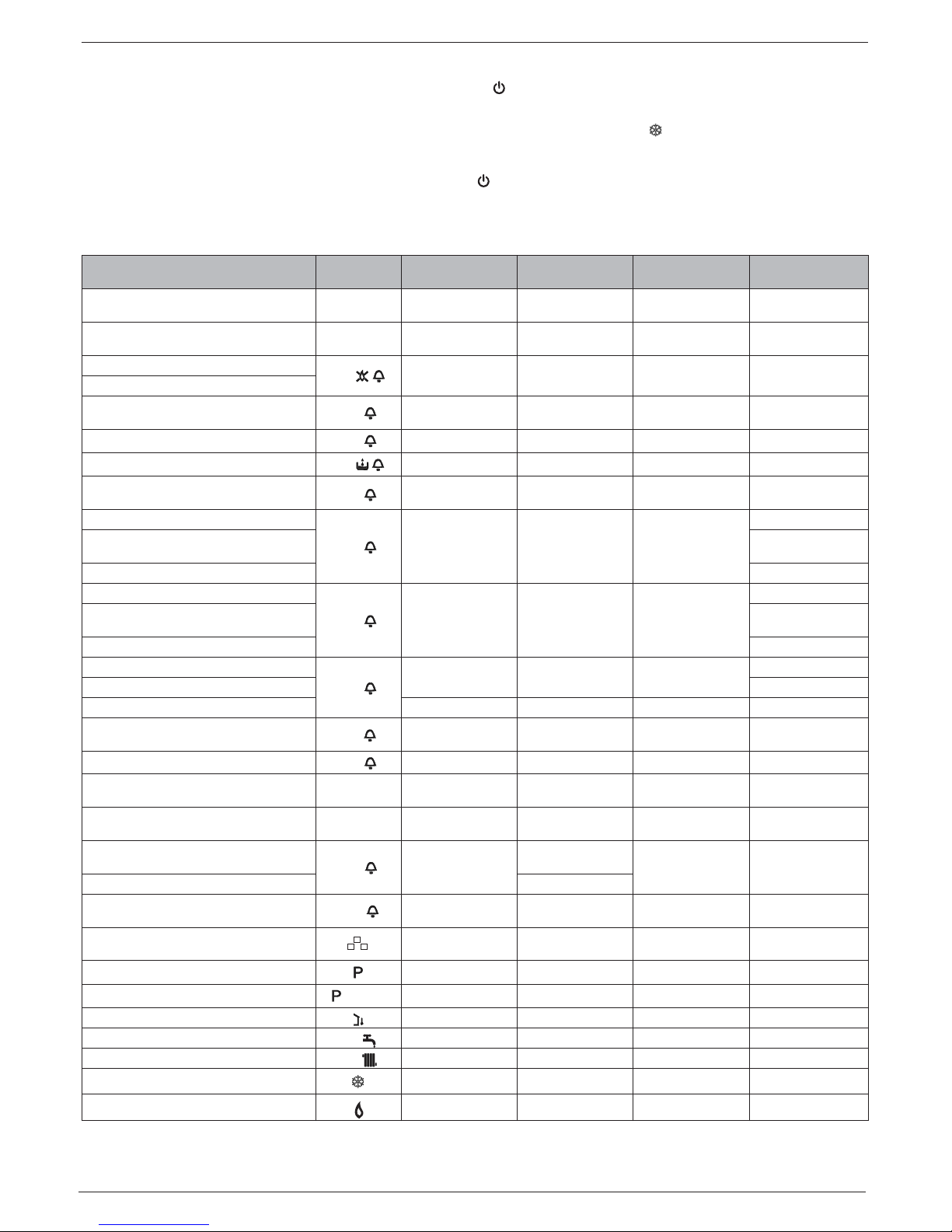
4.3 Light signals and faults
BOILER STATUS
DISPLAY
RED LED YELLOW LED GREEN LED
TYPES OF
ALARMS
Off status(OFF) OFF
fl ashing 0.5 on/
3.5 off
None
Stand-by -
fl ashing 0.5 on/
3.5 off
Signal
ACF alarm lockout module
A01
on Defi nitive lockout
ACF electronics fault alarm
Limit thermostat alarm
A02
fl ashing 0.5 on/
0.5 off
Defi nitive lockout
Tacho fan alarm
A03
on Defi nitive lockout
Water pressure switch alarm
A04
on on Defi nitive lockout
NTC domestic water fault A06
fl ashing 0.5 on/
0.5 off
fl ashing 0.5 on/
0.5 off
Signal
NTC heating outlet fault
A07
on
Temporary stop
Heating outlet probe overtemperature
Temporary then
defi nitive
Outlet/return line probe differential alarm Defi nitive lockout
NTC heating return line fault
A08
on
Temporary stop
Heating return line probe overtemperature
Temporary then
defi nitive
Outlet/return line probe differential alarm Defi nitive lockout
Cleaning the primary heat exchanger
A09
fl ashing 0.5 on/
0.5 off
fl ashing 0.5 on/
0.5 off
Signal
NTC fl ue gases fault Temporary stop
Flue gases probe overtemperature on Defi nitive lockout
False fl ame
A11
fl ashing 0.2 on/
0.2 off
Temporary stop
Low temperature system thermostat alarm
A77
on Temporary stop
Temporary pending ignition
fl ashing 0.5 on/
0.5 off
Temporary stop
Water pressure switch intervention
fl ashing 0.5 on/
0.5 off
Temporary stop
Calibration service
ADJ
fl ashing 0.5 on/
0.5 off
fl ashing 0.5 on/0.5
off
fl ashing 0.5 on/
0.5 off
Signal
Calibration installer
Chimney sweep
ACO
fl ashing 0.5 on/0.5
off
Signal
Vent cycle
fl ashing 0.5 on/
1.0 off
fl ashing 0.5 on/1.0
off
fl ashing 0.5 on/
1.0 off
Signal
Preheating active function on Signal
Preheating heat request
fl ashing
Signal
External probe presence
Signal
Domestic water heat request 60
°C
Signal
Heating heat request 80
°C
Signal
Antifreeze heat request
Signal
Flame present
on Signal
Page 9

9
ENGLISH
To restore operation (deactivate alarms):
Faults A 01-02-03
Position the function selector to (OFF), wait 5-6 seconds then set it to
the required position (summer mode) or (winter mode).
If the reset attempts do not reactivate the boiler, contact the Technical Assistance Centre.
Fault A 04
In addition to the fault code, the digital display shows the symbol
.
Check the pressure value indicated by the water gauge: if it is less than
0.3 bar, position the function selector to (OFF) and adjust the fi lling tap
until the pressure reaches a value between 1 and 1.5 bar. Then position
the mode selector to the desired position (summer) or (winter).
The boiler will perform one purge cycle lasting approximately 2 minutes. If
pressure drops are frequent, request the intervention of the Technical Assistance Service.
Fault A 06
The boiler operates normally but cannot reliably maintain a constant domestic hot water temperature, which remains set at around 50°C. Contact
the Technical Assistance Centre.
Fault A 07 - A 08
Contact the Technical Assistance Centre.
Fault A 09 with fi xed red LED lit
Position the function selector to (OFF), wait 5-6 seconds then set it to
the required position (summer mode) or (winter mode). If the reset attempts
do not reactivate the boiler, request the intervention of the Technical Assistance Service.
Fault A 09 with fl ashing red and green LEDs
The boiler is equipped with an auto-diagnostic system which, based on the
total number of hours in certain operating conditions, can signal the need
to clean the primary exchanger (alarm code 09 with fl ashing red and green
LEDs and fl ue gas meter >2,500). Once the cleaning operation has been
completed, using the special kit supplied as an accessory, the total hour
meter will need to be reset to zero as follows:
- switch off the power supply
- remove the housing
- loosen the fi xing screw then turn the instrument panel
- loosen the fi xing screws on the cover (F) to access the terminal board (fi g. 16)
- while the boiler is powered up, using a small screwdriver included, press
the CO button (fi g. 26) for at least 4 seconds, to check the meter has
been reset, power down then power up the boiler; the meter reading is
shown on the monitor after the “-C-” sign.
Live electrical parts (230 V AC).
Note: the meter resetting procedure should be carried out after each indepth cleaning of the primary exchanger or if this latter is replaced. To
check the status of the total hour meter, multiply the reading by 100 (e.g.
reading of 18 = 1800 total hours; reading of 1 = 100 total hours).
The boiler continues to operate normally even when the alarm is activated.
Fault A 77
This is an automatic-reset fault, if the boiler does not restart, contact the
Technical Assistance Centre.
Fixed yellow LED
Pre-heating function activated
Flashing yellow LED
Combustion analysis in progress.
4.4 Alarm records
The “ALARM RECORDS” function starts automatically once the display has
been on for 2 hours, or immediately by setting the P1 parameter to 1.
The records include all the latest alarms, up to a maximum of 5 alarms, and
they are displayed in sequence by pushing and releasing the P1 button on
the display board. If the records are empty (P0=0) or if tracking the same is
disabled (P1=0), the display function is not available. Alarms are displayed
in reverse order compared to the order in which they occurred: this means
that the last alarm generated is the fi rst to be displayed. To delete the
alarms records, simply set parameter P0 to 0.
NOTE: To get to the P1 button the cover on the control panel must be removed and the display board must be identifi ed (fi g. 37a).
PROGRAMMING PARAMETERS
Functioning of the display can be personalised by programming three parameters:
Param. Default Description
P0 0 Deletion of alarms records
(0 = records empty / 1 = records not empty)
P1 0 Immediate activation of alarm record management
(0 = delayed records management activated / 1 =
immediate records management activated
P2 0 Do not change
envisaged delivery T. - Tshift
KT=
20- min. envisaged external T.
When button P1 on the display (fi g. 37a) is held down for at least 10 sec,
the programming procedure is activated. The three parameters, with their
respective values, are shown in rotation on the display (fi g. 37b). To edit a
parameter value, simply push the P1 button again when the required parameter is displayed, and then hold it down until the value switches from 0 to
1 or vice-versa (approx. 2 sec).
The programming procedure is closed automatically after 5 minutes, or if
there is an electrical power failure
4.5 Boiler confi guration
There is a series of jumpers (JPX) available on the electronic board which
enable the boiler to be confi gured.
To access the board, proceed as follows:
- turn off the main switch on the system
- loosen the fi xing screws on the housing, move the base of the housing
forwards and then upwards to unhook it from the chassis
- undo the fi xing screws (E) from the instrument panel (fi g. 14)
- loosen the screws (F - fi g. 16) to remove the cover of the terminal board
(230V)
JUMPER JP7 - fi g. 38:
preselection of the most suitable heating temperature adjustment fi eld according to the installation type.
Jumper not inserted - standard installation
Standard installation 40-80°C
Jumper inserted - fl oor installation
Floor installation 20-45°C.
In the manufacturing phase, the boiler is confi gured for standard installations.
JP1
Calibration (Range Rated)
JP2 Reset heating timer
JP3 Calibration (see paragraph on “Adjustments”)
JP4 Absolute domestic hot water thermostat selector
JP5 Do not use
JP6 Enable night-time compensation function and continuous pump (only
with external sensor connected)
JP7 Enable management of low temperature/standard installations (see
above)
JP8 Do not use
4.6 Setting the thermoregulation (graphs 1-2-3)
The thermoregulation only operates with the external sensor connected;
once installed, connect the external sensor (accessory available on request)
to the special terminals provided on the boiler terminal board (fi g. 5).
This enables the THERMOREGULATION function.
Selecting the compensation curve
The compensation curve for heating maintains a theoretical temperature of
20°C indoors, when the external temperature is between +20°C and -20°C.
The choice of the curve depends on the minimum external temperature
envisaged (and therefore on the geographical location), and on the delivery
temperature envisaged (and therefore on the type of system). It is carefully
calculated by the installer on the basis of the following formula:
Tshift = 30°C standard installations
25°C fl oor installations
If the calculation produces an intermediate value between two curves, you
are advised to choose the compensation curve nearest the value obtained.
Example: if the value obtained from the calculation is 1,3 this is between
curve 1 and curve 1,5. Choose the nearest curve, i.e. 1,5.
Select the KT using trimmer P3 on the board (see multiwire wiring diagram).
To access P3:
- remove the housing,
- loosen the fi xing screw on the instrument panel
- turn the instrument panel towards you
- loosen the fi xing screws on the terminal board cover
- unhook the board casing
Live electrical parts (230 V AC).
The KT values which can be set are as follows:
standard installation: 1,0-1,5-2,0-2,5-3,0
fl oor installation 0,2-0,4-0,6-0,8
and these are displayed for approximately 3 seconds after rotation of the
trimmer P3.
TYPE OF HEAT REQUEST
Boiler connected to room thermostat (JUMPER 6 not inserted)
The heat request is made by the closure of the room thermostat contact,
while the opening of the contact produces a switch-off. The delivery temperature is automatically calculated by the boiler, although the user may
modify the boiler settings. Using the interface to modify the HEATING, you
Page 10

10
QUADRA GREEN 25 C.S.I.
will not have the HEATING SET-POINT value available, but a value that you
can set as preferred between 15 and 25°C. The modifi cation of this value
will not directly modify the delivery temperature, but will automatically affect
the calculation that determines the value of that temperature, altering the
reference temperature in the system (0 = 20°C).
Boiler connected to a programmable timer (JUMPER JP6 inserted)
With the contact closed, the heat request is made by the delivery sensor, on
the basis of the external temperature, to obtain a nominal indoor temperature on DAY level (20°C). With the contact open, the boiler is not switched
off, but the weather curve is reduced (parallel shift) to NIGHT level (16°C).
This activates the night-time function. The delivery temperature is automatically calculated by the boiler, although the user may modify the boiler settings. Using the interface to modify the HEATING, you will not have the
HEATING SET-POINT value available, but a value that you can set as preferred between 25 and 15°C. The modifi cation of this value will not directly
modify the delivery temperature, but will automatically affect the calculation
that determines the value of that temperature, altering the reference temperature in the system (0 = 20°C for DAY level, and 16°C for NIGHT level).
4.7 Adjustments
The boiler has already been adjusted by the manufacturer during production. If the adjustments need to be made again, for example after extraordinary maintenance, replacement of the gas valve, or conversion from methane gas to LPG, observe the following procedures.
The adjustment of the maximum and minimum output, and of the maximum
and minimum heating and of slow switch-on, must be made strictly in the
sequence indicated, and only by qualifi ed personnel only:
- disconnect the boiler from the power supply
- turn the heating water temperature selector to its maximum
- loosen the fi xing screws (E) on the instrument panel (fi g. 14)
- lift then turn the instrument panel towards you
- loosen the fi xing screws on the cover (F) to access the terminal board (fi g. 16)
- insert the jumpers JP1 and JP3 (fi g. 40)
- power up the boiler
The three LEDs on the instrument panel fl ash simultaneously and the display shows “ADJ” for approximately 4 seconds
Next change the following parameters:
1 - Domestic hot water/absolute maximum
2 - Minimum
3 - Heating maximum
4 - Slow switch-on
as follows:
- turn the heating water temperature selector to set the required value
- press the CO button using a small screwdriver included (fi g. 26) and then
skip to the calibration of the next parameter.
Live electrical parts (230 V AC).
The following icons light up on the monitor:
1.
during domestic hot water/absolute maximum calibration
2.
during minimum calibration
3.
during heating maximum calibration
4.
during slow switch-on calibration
End the procedure by removing jumpers JP1 and JP3 to store these set values in the memory. The function can be ended at any time without storing
the set values in the memory and retaining the original values as follows:
- remove jumpers JP1 and JP3 before all 4 parameters have been set
- set the function selector to (OFF/RESET)
- cut the power supply 15 minutes after it is connected.
Calibration can be carried out without powering up the boiler.
By turning the heating selection knob, the monitor automatically
shows the number of rotations, expressed in hundreds (e.g. 25 =
2,500 rpm).
The function for visualizing the setting parameters is activated by the function selector in summer and in winter, by pressing the CO button on the
circuit board, either with or without request for heat. This function cannot be
activated when connected to a remote control. Upon activating the function
the setting parameters are visualized in the order given below, each for 2
seconds. Each parameter is displayed together with its corresponding icon
and fan rotation speed measured in hundreds
1. Maximum
2. Minimum
3. Max. heating
4. Slow ignition P
5. Max. preset heating
GAS VALVE CALIBRATION
- Connect the boiler to the power supply
- Open the gas tap
- Set the function selector to (OFF/RESET) (monitor off)
- Loosen the screws (E), remove the housing, then lower the instrument
panel towards you (fi g. 14)
- Loosen the fi xing screws on the cover (F) to access the terminal board
(fi g. 16)
- Using a small screwdriver included, press the CO button (fi g. 26)
Live electrical parts (230 V AC).
- Wait for burner ignition.
The display shows “ACO” and the yellow LED fl ashes. The boiler oper-
ates at maximum heat output.
The “combustion analysis” function remains active for a limited time (15
min); if a delivery temperature of 90°C is reached, the burner is switched
off. It will be switched back on when this temperature drops below 78°C.
- Insert the analyser probe in the ports provided in the air distribution box,
after removing the screws from the cover (fi g. 41)
- Press the “combustion analysis” button a second time to reach the number of rotations corresponding to the maximum domestic hot water output
(table 1); the yellow LED continues to fl ash while the red LED is fi xed
- Check the CO2 value: (table 3) if the value does not match the value
given in the table, use the gas valve maximum adjustment screw
- Press the “combustion analysis” button a third time to reach the number
of rotations corresponding to the minimum output (table 2); the yellow
LED continues to fl ash while the green LED is fi xed
- Check the CO2 value: (table 4) if the value does not match the value
given in the table, use the gas valve minimum adjustment screw
- To exit the “combustion analysis” function, turn the control knob
- Remove the fl ue gas probe and refi t the plug
- Close the instrument panel and refi t the housing.
The “combustion analysis” function is automatically deactivated if the board
triggers an alarm. In the event of a fault during the combustion analysis
cycle, carry out the reset procedure.
table 1
MAXIMUM NUMBER OF
FAN ROTATIONS
METHANE
GAS (G20)
LIQUID GAS
(G31)
25 C.S.I. heating - DHW 49 - 61 49 - 61 rpm
table 2
MINIMUM NUMBER OF
FAN ROTATIONS
METHANE
GAS (G20)
LIQUID GAS
(G31)
14 14 rpm
table 3
Max. CO
2
METHANE
GAS (G20)
LIQUID GAS
(G31)
9,0 10,5 %
table 4
Min. CO
2
METHANE
GAS (G20)
LIQUID GAS
(G31)
9,5 10,5 %
4.8 Gas conversion (fi g. 42-43)
Gas conversion from one family of gases to another can also be easily
performed when the boiler is installed.
This operation must be carried out by professionally qualifi ed personnel.
The boiler is designed to operate with methane gas (G20) according to the
product label.
It is possible to convert the boiler to propane gas, using the special kit.
For disassembly, refer to the instructions below:
- switch off the power supply to the boiler and close the gas tap
- remove in sequence: housing and air distribution box cover
- remove the fi xing screw from the instrument panel
- unhook and turn the instrument panel forwards
- remove the gas valve (A)
- remove the nozzle (B) inside the gas valve and replace it with the nozzle
from the kit
- refi t the gas valve
- remove the silencer from the mixer
- open the two half-shells by prising apart the corresponding hooks (C)
- replace the air diaphragm (D) in the silencer
- refi t the air distribution box cover
- re-power the boiler and turn on the gas tap
Page 11

11
ENGLISH
Adjust the boiler as described in the chapter entitled “Adjustments” with
reference to the information on LPG.
Conversion must be carried out by qualifi ed personnel.
Once the conversion is complete, affi x the new identifi cation
label supplied in the kit.
4.9 Checking the combustion parameters
To carry out the combustion analysis, proceed as follows:
- set the main switch of the installation to the “OFF” position
Method 1 - frontal procedure
- turn the selector to position
- chimney sweep function
Method 2 - board procedure
- loosen the fi xing screws (D) on the housing (fi g. 13)
- move the base of the housing forwards and then upwards to unhook it
from the chassis
- loosen the fi xing screws (E) on the instrument panel (fi g. 14)
- lift then turn the instrument panel towards you
- loosen the fi xing screws on the cover (F) to access the terminal board (fi g. 16)
- using a small screwdriver included, press the CO button (fi g. 26)
Live electrical parts (230 V AC).
For both methods
- Wait for burner ignition. The display shows “ACO”, the yellow LED fl ashes and the boiler operates at maximum heat output.
- insert the analyser probe in the ports provided in the air distribution box,
after removing the screws from the cover (fi g. 41)
- check that the CO2 values match those given in the table, if the value
shown is different, change it as indicated in the chapter entitled “Gas
valve calibration”.
- perform the combustion check.
Then:
- remove the analyser probe and close the sockets for combustion analysis with the special screw
- close the instrument panel and refi t the housing
The fl ue gas analysis probe must be fully inserted as far as pos-
sible.
IMPORTANT
Even during the combustion analysis phase, the function that switches the
boiler off when the water temperature reaches the maximum limit (about
90°C) remains enabled.
5 MAINTENANCE
The appliance must be systematically controlled at regular intervals to
make sure it works correctly and effi ciently and conforms to legislative provisions in force.
The frequency of controls depends on the conditions of installation and
usage, it being anyhow necessary to have a complete check carried out by
authorized personnel from the Servicing Centre every year.
- Check and compare the boiler’s performance with the relative specifi cations. Any cause of visible deterioration must be immediately identifi ed
and eliminated.
- Closely inspect the boiler for signs of damages or deterioration, particularly with the drainage and aspiration system and electrical apparatus.
- Check and adjust – where necessary – all the burner’s parameters.
- Check and adjust – where necessary – the system’s pressure.
- Analyze combustion. Compare results with the product’s specifi cation.
Any loss in performance must be identifi ed and corrected by fi nding and
eliminating the cause.
- Make sure the main heat exchanger is clean and free of any residuals or
obstruction.
- Check and clean – where necessary – the condensation tray to make
sure it works properly.
IMPORTANT: always switch off the power to the appliance and close the
gas by the gas cock on the boiler before carrying out any maintenance and
cleaning jobs on the boiler.
Do not clean the appliance or any latter part with fl ammable substances
(e.g. petrol, alcohol, etc.).
Do not clean panelling, enamelled and plastic parts with paint solvents.
Panels must be cleaned with ordinary soap and water only.
The fl ame side of the burner is made of state-of-the-art material.
Being fragile:
- be particularly careful when handling, mounting or dismantling the burner
and adjacent components (e.g. electrodes, insulation panelling etc.)
- avoid direct contact with any cleaning appliance (e.g. brushes, aspirators, blowers, etc.).
This component does not need any maintenance, please do not remove it
from its housing, save where the O-ring may have to be replaced.
The manufacturer declines all responsibility in cases of damages due to
failing to observe the above.
6 SERIAL NUMBER PLATE
Domestic hot water function
Heating function
Qn Nominal heat delivery
Pn Nominal heat output
Qm Reduced heat delivery
Pm Reduced heat output
IP Degree of Protection
Pmw Maximum DHW pressure
Pms Maximum heating pressure
T Temperature
ŋ Performance
D Specifi c fl ow rate
NOx NOx class
0694/
00
Serial N.
00000000000
230 V ~ 50 Hz W
****
NOx:
Pms = T=
η
Caldaia Condensazione
Condensing boiler
Caldera de condensación
Centrala in condensatie
Chaudiere a condensation
Brennwertkessel
regolata per:
set at:
calibrado:
reglat:
réglage:
engestellt auf:
Via Risorgimento 13 - 23900 Lecco (LC) Italy
SK-CZ-LT-GR-HU:
IPX5D
RO-AT:
Pmw = T=
D:
80-60 °C
80-60 °
C
50-30 °C
Qn =
Pn =
Qn =
Pn =
Qm =
Pm =
Pn =
DK-EE-LV:
ES-PT-SI:
IT:
3CEp
Page 12

12
QUADRA GREEN 25 C.S.I.
USER GUIDE
1a GENERAL WARNINGS AND SAFETY
The instruction manual is an integral part of the product and it must therefore be kept carefully and must accompany the appliance; if the manual
is lost or damaged, another copy must be requested from the Technical
Assistance Service.
Boiler installation and any other assistance and maintenance opera-
tions must be carried out by qualifi ed personnel according to the
provisions of local legislation.
For installation, it is advisable to contact specialised personnel.
The boiler must only be used for the application foreseen by the
manufacturer. The manufacturer shall not be liable for any damage
to persons, animals or property due to errors in installation, calibra-
tion, maintenance or due to improper use.
The safety and automatic adjustment devices must not be modifi ed,
during the system life cycle, by the manufacturer or supplier.
This appliance produces hot water, therefore it must be connected
to a heating system and/or a domestic hot water mains, compatible
with its performance and output.
In case of water leakage, close the water supply and contact the
Technical Assistance Service immediately.
In case of absence for long periods time, close the gas supply and
switch off the electrical supply main switch. If there is a risk of frost,
drain the boiler.
From time to time check that the operating pressure of the hydraulic
system does not go below 1 bar.
In case of failure and/or malfunctioning, deactivate the appliance,
and do not try to repair or operate directly on it.
Appliance maintenance must be carried out at least once a year:
scheduling it with the Technical Assistance Service will avoid wasting
time and money.
Boiler use requires strict observation of some basic safety rules:
Do not use the appliance in any manner other than its intended
purpose.
It is dangerous to touch the appliance with wet or damp body parts
and/or when barefoot.
Under no circumstances cover the intake grids, dissipation grids and
ventilation vents in the installation room with cloths, paper or any
other material.
Do not use electrical switches, telephone or any other object that
causes sparks if there is a smell of gas. Ventilate the room by open-
ing doors and windows and close the central gas tap.
Do not place anything in the boiler.
Do not perform any cleaning operation if the appliance is not discon-
nected from the mains power supply.
Do not cover or reduce ventilation opening of the room where the
generator is installed.
Do not leave containers and infl ammable products in the installation
room.
Do not attempt to repair the appliance in case of failure and/or mal-
functioning.
It is dangerous to pull or twist the electric cables.
Children or unskilled persons must not use the appliance.
Do not carry out operations on sealed elements.
For better use, remember that:
- periodic external cleaning with soapy water not only improves its appearance but also preserves panelling from corrosion, extending its life cycle;
- if the wall-mounted boiler is enclosed in a hanging unit, leave at least 5
cm for ventilation and maintenance;
- installation of a room thermostat will greatly improve comfort, a more rational use of the heat and energy saving; the boiler can also be connected
to a programmable timer in order to control the switching on and off of the
appliance during the day or week.
2a SWITCHING ON THE APPLIANCE
Every time the appliance is powered up, a series of data is shown on the
display including the fl ue gas sensor meter reading (-C- XX) (see paragraph
4.3 - fault A09); the automatic purge cycle then starts, lasting around 2 min-
utes. During this phase, the three LEDs light up alternately and the symbol
is shown on the monitor (fi g. 25).
To start up the boiler it is necessary to carry out the following operations:
- power the boiler
- open the gas tap to allow the fl ow of fuel
- set the room thermostat to the required temperature (~20°C)
- turn the mode selector to the desired position:
Winter mode: by turning the mode selector (fi g. 27) within the marked area,
the boiler provides domestic hot water and heating. If there is a heat request, the boiler switches on and the boiler status indicator LED lights up
with a fi xed green light. The digital monitor indicates the heating water temperature, the icon to indicate heating and the fl ame icon (fi g. 29).
If there is a domestic hot water request, the boiler switches on and the
boiler status indicator LED lights up with a fi xed green light.
The digital display shows the hot water system temperature, the icon to
indicate the hot water supply and the fl ame icon (fi g. 30).
Adjustment of the heating water temperature
To adjust the heating water temperature, turn the knob with symbol
(fi g. 27) within the marked area.
Adjusting heating water temperature with an external probe connected
When an external probe is connected, the value of the delivery temperature
is automatically chosen by the system which rapidly adjusts ambient temperature to the changes in external temperature.
To increase or decrease the temperature with respect to the value automatically calculated by the electronic board, turn the heating water selector (Fig.
12.6) clockwise to increase and anticlockwise to decrease.
Adjustment settings range from comfort levels - 5 to + 5 which are indicated
on the digital display when the knob is turned.
Summer mode: turning the selector to the summer mode symbol
(fi g.
28) activates the traditional domestic hot water only function.
If there is a domestic hot water request, the boiler switches on and the
boiler status indicator LED lights up with a fi xed green light. The digital
monitor indicates the domestic hot water temperature, the icon to indicate
the hot water supply and the fl ame icon (fi g. 30).
Pre-heating (faster hot water): turning the domestic hot water temperature adjustment knob to the
symbol (fi g. 31) activates the pre-heating
function. Bring the domestic hot water temperature adjustment knob back
to the required position.
This function keeps the water in the domestic hot water exchanger hot, to
reduce standby times when a request is made.
When the pre-heating function is enabled, the yellow LED next to the
symbol is lit.
The monitor indicates the delivery temperature of the heating water or the
domestic hot water, according to the current request.
During burner ignition following a pre-heating request, the monitor indicates
the symbol.
To deactivate the pre-heating function, rotate the domestic hot water temperature adjustment knob back to the symbol. The yellow LED will
switch off. Bring the domestic hot water temperature adjustment knob back
to the required position.
This function cannot be activated when the boiler is OFF: function selector
(fi g.32) to (OFF).
Adjustment of domestic hot water temperature
To adjust the domestic hot water temperature (bathrooms, shower, kitchen,
etc.), turn the knob with the
symbol (fi g. 28) rotate clockwise to increase
the temperature and anticlockwise to reduce it. On the control panel, the
green LED fl ashes ON for 0.5 seconds then OFF for 3.5 seconds.
The boiler is standby status until, after a heat request, the burner switches on and the indicator LED turns fi xed green to indicate fl ame presence.
The boiler continues to operate until the temperatures set on the boiler are
reached, or the heat request is met; after which it goes back on standby.
If the red LED indicator near the symbol (fi g. 34) on the control panel
lights up, this means the boiler is in temporary shutdown status (see the
chapter on Light signals and faults).
The digital monitor indicates the fault code detected (fi g. 34).
Automatic Temperature Control System function (S.A.R.A.) fi g. 35
Setting the heating water temperature selector to the area marked “AUTO”,
activates the automatic temperature control system (frequency 0.1 sec. on;
then 0.1 sec. off; for 0.5 seconds): according to the temperature set on the
room thermostat and the time taken to reach it, the boiler varies automatically the heating water temperature reducing the operating time, allowing
greater ease of operation and energy saving. On the control panel, the
green LED fl ashes ON for 0.5 seconds, OFF for 3.5 seconds.
Reset function
To restore operation, set the function selector to
(“OFF”) (fi g. 32), wait
5-6 seconds then set it to the required position, checking that the red indicator light is OFF. At this point the boiler will automatically start and the red
lamp switches on in green.
N.B. If the attempt to reset the appliance does not activate operation, contact the Technical Assistance Service.
Page 13
13
ENGLISH
3a SWITCHING OFF
Temporary switch-off
In case of absence for short periods of time, set the mode selector (fi g. 32) to (OFF).
In this way (leaving the electricity and fuel supplies enabled), the boiler is protected by:
Anti-frost device: when the temperature of the water in the boiler falls below 5°C, the circulator and, if necessary, the burner are activated at minimum output
levels to bring the water temperature back to the values for safety (35°C). During the anti-frost cycle, the symbol (fi g. 36) appears on the digital monitor.
Circulator anti-blocking function: an operation cycle is activated every 24 hours.
Switching off for long periods
In case of absence for long periods of time, set the mode selector (fi g. 32) to
(OFF). Turn the main system switch OFF. Close the fuel and water taps of
the heating and domestic hot water system. In this case, anti-frost device is deactivated: drain the systems, in case of risk of frost.
4a LIGHT SIGNALS AND FAULTS
The operating status of the boiler is shown on the digital display, below is a list of the types of displays.
BOILER STATUS
DISPLAY
RED LED YELLOW LED GREEN LED
TYPES OF
ALARMS
Off status(OFF) OFF
fl ashing 0.5 on/
3.5 off
None
Stand-by -
fl ashing 0.5 on/
3.5 off
Signal
ACF alarm lockout module
A01
on Defi nitive lockout
ACF electronics fault alarm
Limit thermostat alarm
A02
fl ashing 0.5 on/
0.5 off
Defi nitive lockout
Tacho fan alarm
A03
on Defi nitive lockout
Water pressure switch alarm
A04
on on Defi nitive lockout
NTC domestic water fault A06
fl ashing 0.5 on/
0.5 off
fl ashing 0.5 on/
0.5 off
Signal
NTC heating outlet fault
A07
on
Temporary stop
Heating outlet probe overtemperature
Temporary then
defi nitive
Outlet/return line probe differential alarm Defi nitive lockout
NTC heating return line fault
A08
on
Temporary stop
Heating return line probe overtemperature
Temporary then
defi nitive
Outlet/return line probe differential alarm Defi nitive lockout
Cleaning the primary heat exchanger
A09
fl ashing 0.5 on/
0.5 off
fl ashing 0.5 on/
0.5 off
Signal
NTC fl ue gases fault Temporary stop
Flue gases probe overtemperature on Defi nitive lockout
False fl ame
A11
fl ashing 0.2 on/
0.2 off
Temporary stop
Low temperature system thermostat alarm
A77
on Temporary stop
Temporary pending ignition
fl ashing 0.5 on/
0.5 off
Temporary stop
Water pressure switch intervention
fl ashing 0.5 on/
0.5 off
Temporary stop
Calibration service
ADJ
fl ashing 0.5 on/
0.5 off
fl ashing 0.5 on/0.5
off
fl ashing 0.5 on/
0.5 off
Signal
Calibration installer
Chimney sweep
ACO
fl ashing 0.5 on/0.5
off
Signal
Vent cycle
fl ashing 0.5 on/
1.0 off
fl ashing 0.5 on/1.0
off
fl ashing 0.5 on/
1.0 off
Signal
Preheating active function on Signal
Preheating heat request
fl ashing
Signal
External probe presence
Signal
Domestic water heat request 60
°C
Signal
Heating heat request 80
°C
Signal
Antifreeze heat request
Signal
Flame present
on Signal
Page 14
14
QUADRA GREEN 25 C.S.I.
To restore operation (deactivate alarms):
Faults A 01-02-03
Position the function selector to (OFF), wait 5-6 seconds then set it to
the required position (summer mode) or (winter mode).
If the reset attempts do not reactivate the boiler, contact the Technical Assistance Centre.
Fault A 04
In addition to the fault code, the digital display shows the symbol
.
Check the pressure value indicated by the water gauge:
if it is less than 0.3 bar, position the function selector to OFF (fi g. 32) and
adjust the fi lling tap (C- fi g 17) until the pressure reaches a value between
1 and 1.5 bar.
Then position the mode s
elector to the desired
position (summer) or
(winter).
The boiler will perform one purge cycle lasting approximately 2 minutes.
If pressure drops are frequent, request the intervention of the Technical
Assistance Service.
Fault A 06
The boiler operates normally but cannot reliably maintain a constant domestic hot water temperature, which remains set at around 50°C. Contact
the Technical Assistance Centre.
Fault A 07
Contact the Technical Assistance Centre.
Fault A 08
Contact the Technical Assistance Centre.
Fault A 09 with fi xed red LED lit
Position the function selector to
(OFF), wait 5-6 seconds then set it to the
required position (summer mode) or (winter mode).
If the reset attempts do not reactivate the boiler, request the intervention of
the Technical Assistance Service.
Fault A 09 with fl ashing red and green LEDs
Contact the Technical Assistance Centre
Fault A77
This is an automatic-reset fault, if the boiler does not restart, contact the
Technical Assistance Centre.
Fixed yellow LED
Pre-heating function activated
Flashing yellow LED
Combustion analysis in progress.
Page 15

15
ENGLISH
DESCRIPTION QUADRA GREEN 25 C.S.I.
Heating Heat input kW 20,00
kcal/h 17.200
Maximum heat output (80/60°) kW 19,50
kcal/h 16.770
Maximum heat output (50°/30°) kW 20,84
kcal/h 17.922
Minimum heat input kW 5,00
kcal/h 4.300
Minimum heat output (80°/60°) kW 4,91
kcal/h 4.218
Minimum heat output (50°/30°) kW 5,36
kcal/h 4.610
Nominal Range Rated heat output (Qn) kW 20,00
kcal/h 17.200
Minimum Range Rated heat output (Qm) kW 5,00
kcal/h 4.300
DHW Heat input kW 25,00
kcal/h 21.500
Maximum heat output (*) kW 25,00
21.500
Minimum heat input kW 5,00
kcal/h 4.300
Minimum heat output (*) kW 5,00
kcal/h 4.300
(*) average value of various DHW operating conditions
Useful effi ciency (Pn max - Pn min) % 97,5-98,1
Effi ciency 30% (47° return) % 102,2
Combustion performance % 97,9
Useful effi ciency Pn max - Pn min (50°/30°) % 104,2-107,2
Useful effi ciency 30% (30° return) % 108,9
Average Range Rated effi ciency Pn (80°/60°) % 97,8
Average Range Rated effi ciency Pn (50°/30°) % 106,0
Electric power W 110
Category II2H3P
Country of destination Power supply voltage V - Hz 230-50
Degree of Protection IP X5D
Pressure drops on fl ue with burner on % 2,10
Pressure drops on fl ue with burner off % 0,06
Heating operation
Pressure - maximum temperature bar 3-90
Minimum pressure for standard operation bar 0,25-0,45
Selection fi eld of heating water temperature °C 20/45-40/80
Pump: maximum head available mbar 200
for system capacity l/h 800
Membrane expansion tank l 8
Expansion tank pre-charge bar 1
DHW operation
Maximum pressure bar 6
Minimum pressure bar 0,15
Hot water quantity with ∆t 25°C l/min 14,3
with ∆t 30°C l/min 11,9
with ∆t 35°C l/min 10,2
DHW minimum output l/min 2
Selection fi eld of DHW temperature °C
37-60
Flow regulator l/min 10
Gas pressure
Methane gas nominal pressure (G 20) mbar 20
LPG liquid gas nominal pressure (G 31) mbar 37
Hydraulic connections
Heating input - output Ø 3/4”
DHW input-output Ø 1/2”
Gas input Ø 3/4”
TECHNICAL DATA
Page 16

16
QUADRA GREEN 25 C.S.I.
Multigas table
DESCRIPTION
QUADRA GREEN 25 C.S.I.
Boiler dimensions
Height mm 715
Width mm 405
Depth of housing mm 250
Boiler weight kg 29
Flow rate (G20)
Air capacity Nm
3/
h 24,908 31,135
Flue gas capacity Nm
3
/h 26,914 33,642
Mass fl ow of fl ue gas (max-min) gr/s 9,025-2,140 11,282-2,140
Flow rate (G31)
Air capacity Nm
3/
h 24,192 30,240
Flue gas capacity Nm
3
/h 24,267 31,209
Mass fl ow of fl ue gas (max-min) gr/s 8,410-2,103 10,513-2,103
Fan performance
Residual head of concentric pipes 0.85m Pa 30
Residual head of separate pipes 0.5m Pa 90
Residual head of boiler without pipes Pa 100
Concentric fl ue gas discharge pipes
Diameter mm 60-100
Maximum length m 5,85
Drop due to insertion of a 45°/90° bend m
1,3/1,6
Hole in wall (diameter) mm 105
Concentric fl ue gas discharge pipes
Diameter mm 80-125
Maximum length m 15,3
Losses for a 45°/90° bend m 1/1,5
Hole in wall (diameter) mm 130
Separate fl ue gas discharge pipes
Diameter mm 80
Maximum length m 45+45
Losses for a 45°/90° bend m 1/1,5
Installation B23P–B53P
Diameter mm 80
Maximum length of drainage pipe m 70
NOx class class 5
Emission values at max. and min. rate of gas G20*
Maximum - Minimum CO s.a. less than ppm 180 - 20
CO
2
%
9,0 - 9,5
NOx s.a. lower than ppm 30 - 20
Flue gas temperature °C 65 - 58
* Check performed with concentric pipe ø 60-100, length 0.85m - water temperature 80-60°C
DESCRIPTION
Methane gas
(G20)
Propane (G31)
Lower Wobbe index (at 15°C-1013 mbar) MJ/m
3
S 45,67 70,69
Net Calorifi c Value MJ/m
3
S 34,02 88
Supply nominal pressure mbar (mm W.C.) 20 (203,9) 37 (377,3)
Supply minimum pressure mbar (mm W.C.) 10 (102,0)
Diaphragm (number of holes) Number 1 1
Diaphragm (diameter of holes) mm 4,8 3,8
Silencer diaphragm (diameter) mm 31 27
Heating maximum gas capacity Sm
3
/h 2,12
kg/h 1,55
DHW maximum gas capacity Sm
3
/h 2,64
kg/h 1,94
Heating minimum gas capacity Sm
3
/h 0,53
kg/h 0,39
DHW minimum gas capacity Sm
3
/h 0,53
kg/h 0,39
Number of fan rotations with slow switch-on rpm 4.000 4.000
Maximum number of fan rotations (heating) rpm 4.900 4.900
Maximum number of fan rotations (DHW) rpm 6.100 6.100
Minimum number of fan rotations (heating) rpm 1.400 1.400
Minimum number of fan rotations (DHW) rpm 1.400 1.400
Page 17

17
POLSKI
1 -
OGÓLNE URZĄDZENIA ZABEZPIECZAJĄCE
Nasze kotły zostały skonstruowane a następnie sprawdzone w
najmniejszych szczegółach, aby uchronić użytkownika i instalatora
przed jakimkolwiek niebezpieczeństwem. W celu uniknięcia porażenia prądem elektrycznym instalator po zamontowaniu urządzenia
musi sprawdzić poprawność podłączeń elektrycznych, a w szczególności to czy żaden z przewodów nie wystaje z obudowy ochronnej.
Niniejsza instrukcja instalacji stanowi - wraz z instrukcją obsługi przeznaczoną dla użytkownika – nieodłączną część urządzenia. Należy
więc upewnić się, czy wchodzi w skład jego wyposażenia, również
w razie przekazania go innemu właścicielowi czy użytkownikowi lub
przeniesieniu go do innej instalacji. W razie jej uszkodzenia bądź utraty
proszę o kontakt z producentem w celu uzyskania nowej kopii.
Instalacja kotła oraz wszelkie inne czynności serwisowe i konser-
wacyjne muszą być wykonane przez Autoryzowanego Serwisanta/
Instalatora Beretta zgodnie z obowiązującymi przepisami.
Instalator ma obowiązek podstawowego przeszkolenia użytkownika
z zakresu obsługi urządzenia oraz bezpieczeństwa.
Kocioł powinien być użytkowany zgodnie z przeznaczeniem. Wyklu-
cza się wszelką odpowiedzialność producenta/importera, z powodu
szkód wynikających z błędnej instalacji, regulacji, konserwacji lub
niewłaściwego użytkowania.
Po usunięciu opakowania należy upewnić się, czy urządzenie jest
kompletne i nieuszkodzone. W przeciwnym wypadku należy natychmiast zwrócić się do sprzedawcy, u którego zostało ono zakupione.
Spust zaworu bezpieczeństwa musi być podłączony do właściwego
systemu odprowadzającego. Producent/ importer urządzenia nie
ponosi odpowiedzialności za ewentualne szkody spowodowane
zadziałaniem zaworu bezpieczeństwa.
Wszelkie materiały opakunkowe należy wyrzucić do odpowiednich
pojemników w punktach zbiórki odpadów.
Odpady należy usuwać z troską o ludzkie zdrowie, bez stosowania
procedur lub metod, które mogą negatywnie wpływać na środowisko.
Podczas instalacji należy pouczyć użytkownika, że:
- w razie wycieków wody należy zamknąć jej dopływ i natychmiast
zwrócić się do Autoryzowanego Serwisu Beretta,
- ciśnienie robocze w instalacji musi zawierać się pomiędzy 1 a 2
bar i nie może przekroczyć 3 bar. W razie potrzeby należy ponowić
procedurę opisaną w rozdziale: „Napełnianie instalacji”:
- w razie nie użytkowania kotła przez dłuższy okres czasu zaleca
się aby Autoryzowany Serwis Beretta wykonał następujące
czynności:
- ustawienie wyłącznika głównego urządzenia oraz wyłącznika
głównego całej instalacji w pozycji “wyłączony”
- zamknięcie kurków gazu oraz wody, zarówno obiegu centralnego
ogrzewania, jak i ciepłej wody użytkowej
- opróżnienie obiegu centralnego ogrzewania oraz ciepłej wody
użytkowej, jeśli zachodzi niebezpieczeństwo zamarzania.
- konserwację kotła należy przeprowadzać co najmniej raz w roku.
Usługę taka należy rezerwować z wyprzedzeniem w Autoryzowanym Serwisie Beretta.
Dla zapewnienia bezpieczeństwa należy pamiętać, że:
dzieci oraz osoby niesamodzielne bez asysty nie powinny użytkować
urządzenia,
niebezpieczne jest włączanie jakichkolwiek urządzeń elektrycznych,
jak na przykład wyłączników, elektrycznych artykułów gospodarstwa
domowego, itp., jeśli czuje się w otoczeniu rozchodzący zapach
gazu. W przypadku ulatniania się gazu należy natychmiast wywietrzyć pomieszczenie otwierając szeroko okna i drzwi; zamknąć
główny kurek gazu; niezwłocznie skontaktować się z Autoryzowanym
Serwisem Beretta,
nie należy dotykać urządzenia mokrymi lub wilgotnymi częściami
ciała i/lub będąc boso,
przed przystąpieniem do wykonania czynności związanych z czysz-
czeniem należy odłączyć urządzenie od sieci elektrycznej ustawiając
INSTRUKCJA INSTALACYJNA
PL
POLSKI
dwubiegunowy wyłącznik instalacji oraz pokrętło wyboru funkcji
znajdujące się na panelu sterowania kotła w pozycjach “wyłączony”,
zabronione jest przeprowadzanie jakichkolwiek modyfi kacji urządzeń
zabezpieczających lub regulacyjnych bez zezwolenia lub odpowiednich wskazówek producenta / dystrybutora,
nigdy nie należy szarpać, odłączać, skręcać przewodów elektrycz-
nych wychodzących z kotła, nawet wtedy jeśli jest on odłączony od
sieci elektrycznej,
nie należy dopuścić do zatkania lub zmniejszenia prześwitu otworów
wentylacyjnych pomieszczenia, w którym zainstalowany jest gazowy
kocioł grzewczy,
nie należy pozostawiać pojemników oraz substancji łatwopalnych w
pomieszczeniu, w którym zainstalowane jest urządzenie,
nie należy pozostawiać części opakowania w miejscach dostępnych
dzieciom,
nie należy zatykać przyłącza do odpływu kondensatu
2 - OPIS KOTŁA
Quadra Green C.S.I. jest kondensacyjnym kotłem wiszącym Typu C prze-
znaczonym dla potrzeb centralnego ogrzewania i ciepłej wody użytkowej.
Możliwe są następujące układy odprowadzania spalin: B23P, B53P, C13,
C23, C33, C43, C53, C63, C83, C93, C13x, C33x, C43x, C53x, C63x,
C83x, C93x.
3 - MONTAŻ KOTŁA
3.1 - Warunki instalowania kotła
Instalacja gazowego kotła grzewczego musi być przeprowadzona przez
wykwalifi kowany personel zgodnie z regulującymi to przepisami. Warunkiem instalowania kotła u odbiorcy jest zapewnienie dostawy gazu do celów grzewczych. Wykonanie instalacji wewnętrznej powinno być zgodne z
obowiązującymi przepisami w tym zakresie. Podczas instalowania należy
zawsze przestrzegać lokalnych zarządzeń Straży Pożarnej, zakładu gazownictwa oraz ewentualnych rozporządzeń władz lokalnych.
Pomieszczenie, w którym ma być zainstalowany kocioł powinno odpowiadać obowiązującym przepisom dotyczącym instalowania aparatów
gazowych; a zwłaszcza Rozporządzeniu Ministra Infrastruktury z dnia
12 kwietnia 2002 roku w sprawie warunków technicznych, jakim powinny
odpowiadać budynki i ich usytuowanie (Dz. U. 2002 nr 75 poz. 690 wraz
z późniejszymi zmianami) i normę dotyczącą instalowania kotłów grzewczych w pomieszczeniach wyposażonych w wannę lub natrysk z uwagi na
stopień zapewnionej ochrony obudowy (IP).
LOKALIZACJA
Kocioł posiada zabezpieczenia, które gwarantują prawidłową eksploatację
w zakresie temperatur od 0°C do 60°C.
W celu wykorzystania tego zabezpieczenia (bazującego na pracy palnika)
kocioł musi mieć możliwość włączenia się. Każdy stan wstrzymania (na
przykład brak gazu lub zasilania elektrycznego bądź blokada kotła) wyłącza
zabezpieczenia. Jeżeli urządzenie jest pozostawione bez zasilania przez
dłuższy okres czasu w miejscach, gdzie temperatury mogą spadać poniżej 0°C, nie ma konieczności opróżniania układu grzewczego. Zaleca się
wówczas dodanie dobrej jakości płynu przeciw zamarzaniu do układu c.o.
Należy ściśle przestrzegać instrukcji producenta w odniesieniu nie tylko do
stężenia roztworu płynu przeciw zamarzaniu dla minimalnej temperatury,
w jakiej ma być utrzymywany układ, ale również do trwałości i utylizacji
samego płynu.
Dla układu c.w.u. zalecamy opróżnienie układu. Elementy podzespołów
kotła są odporne na działanie płynów przeciw zamarzaniu na bazie glikolu
propylenowego (maks. 40%).
MINIMALNE ODLEGŁOŚCI
Aby umożliwić dostęp do wnętrza kotła grzewczego w celu wykonania normalnych czynności konserwacyjnych, niezbędne jest uwzględnienie, w momencie
jego instalacji, minimalnych przewidzianych do tego odległości. (Rys. 9).
W celu właściwego montażu kotła grzewczego na ścianie, należy pamiętać
o tym, że:
- nie może on być zamontowany nad piecem kuchennym lub innym urządzeniem służącym do gotowania
- nie wolno pozostawiać substancji łatwopalnych w pomieszczeniu, w którym zamontowany jest kocioł
- łatwo nagrzewające się ściany (na przykład drewniane) muszą być pokryte właściwą izolacją ochronną.
W niektórych częściach instrukcji użyte zostały umowne oznaczenia:
UWAGA = w odniesieniu do czynności wymagających szczególnej
ostrożności oraz odpowiedniego przygotowania
ZABRONIONE = odniesieniu do czynności, których w żadnym wypadku
NIE MOŻNA wykonywać.
RUG Riello Urządzenia Grzewcze S.A.
ul. Kociewska 28/30 87-100 Toruń
Bezpłatna infolinia 0 801 804 800
info@beretta.pl
Page 18

18
QUADRA GREEN 25 C.S.I.
UWAGA
Przed zamontowaniem kotła zaleca się staranne przepłukanie / oczyszczenie wszystkich przewodów rurowych w instalacji w celu usunięcia ewentualnych zanieczyszczeń, które mogłyby powodować niewłaściwe funkcjonowanie urządzenia.
Należy podłączyć rozdzielacz spustowy kotła do odpowiedniej sieci kanalizacyjnej (szczegóły w rozdziale 3.5).
Układ c.w.u. nie potrzebuje zaworu bezpieczeństwa, ale zalecane jest
upewnienie się, że ciśnienie wody w sieci wodociągowej nie przekracza
6 bar. W razie wątpliwości należy zainstalować reduktor ciśnienia. Przed
uruchomieniem należy upewnić się, że kocioł jest przystosowany do spalania gazu doprowadzonego w instalacji zasilającej; można to odczytać na
opakowaniu lub etykiecie wskazującej typ gazu.
Należy podkreślić, że przewody spalinowe mogą pracować pod ciśnieniem,
a zatem połączenia elementów komina muszą być wykonane szczelnie.
3.2 Czyszczenie instalacji i charakterystyka wody obiegu c.o.
Przed zamontowaniem i uruchomieniem kotła należy przeprowadzić czyszczenie zapobiegawcze instalacji centralnego ogrzewania. W celu zagwarantowania poprawnego funkcjonowania produktu, po każdej operacji czyszczenia, dolewania dodatków i/lub środków chemicznych do instalacji sprawdzić
czy charakterystyka wody zawiera się w podanych w tabeli wartościach.
Parametry Jednostka Woda obiegu
c.o.
Woda
napełniana
pH 7 - 8
Twardość ºF
15-20
Klarowność
Przeźroczysta
3.3 Zabezpieczenie kotła na ścianie oraz połączenia
hydrauliczne
Aby bezpiecznie zamontować kocioł na ścianie należy użyć listwy montażowej (rys. 10) dostarczanej razem z kotłem. Pozycje oraz średnice przyłączy
hydraulicznych zostały podane poniżej:
M zasilanie c.o. 3/4”
AC zasilanie c.w.u. 1/2”
G podłączenie gazu 3/4”
AF wejście z.w. 1/2”
R powrót c.o. 3/4”
3.4 Montaż sondy zewnętrznej (rys. 11)
Prawidłowe umiejscowienie sondy warunkuje prawidłowe jej działanie.
MONTAŻ I PODŁĄCZENIE SONDY ZEWNĘTRZNEJ
Sonda musi być zainstalowana na zewnątrz ogrzewanego budynku, na wysokości 2/3 ściany PÓŁNOCNEJ lub PÓŁNOCNOZACHODNIEJ, w miejscu bez dodatkowych elementów takich jak kominy, drzwi, okna, mogących
zakłócić prawidłowy odczyt temperatury.
Połączenie elektryczne sondy zewnętrznej wykonuje się za pomocą przewodu dwużyłowego 0,5-1mm2 (brak na wyposażeniu). Maksymalna długość przewodu łączącego sondę zewnętrzną z kotłem wynosi 30m. Przy
podłączeniu sondy zewnętrznej nie jest istotne zachowanie biegunowości.
Przewód łączący sondę zewnętrzną z kotłem nie powinien mieć żadnych
połączeń. Jeśli zajdzie taka konieczność wówczas należy to połączenie zaizolować i odpowiednio chronić. W przypadku układania przewodu łączącego sondę i kocioł wraz z innymi przewodami, należy odseparować go od
przewodów będących pod napięciem 230V.
MONTAŻ SONDY NA ŚCIANIE ZEWNĘTRZNEJ BUDYNKU
Sonda musi być zamontowana na gładkiej powierzchni. W przypadku ściany wykonanej z nierównej cegły lub o nieregularnym kształcie należy w
miejscu kontaktu sondy ze ścianą wygładzić powierzchnię. Zdjąć pokrywkę
puszki zabezpieczającej sondę poprzez odkręcenie jej w kierunku przeciwnym do kierunku ruchu wskazówek zegara. Przymierzyć punkt montażowy,
wywiercić otwór 5x25 i włożyć kołek. Należy wyjąć płytkę z wewnątrz obudowy sondy. Przyłożyć obudowę i umocować ją za pomocą wkręta. Poluzuj
śrubę znajdującą się w obudowie sondy, aby umożliwić umieszczenie przewodu, który należy podłączyć do płytki.
Należy pamiętać o dokręceniu śruby, przez którą przechodzi prze-
wód, w celu uniknięcia dostania się wilgoci do wewnątrz obudowy
sondy.
Umieścić płytkę z powrotem w obudowie sondy. Zamknąć pokrywkę zabezpieczającą sondę poprzez zakręcenie jej w kierunku zgodnym z kierunkiem
ruchu wskazówek zegara.
Przymocować w prawidłowy sposób przewód sondy.
3.5 Zbiór kondensatu
Instalacja musi być tak przeprowadzona aby uniknąć zamarznięcia kondensatu produkowanego przez kocioł (np. poprzez izolację). Należy zain-
stalować odbiór kondensatu na bazie polipropylenu (łatwo dostępnego
na rynku) pod kotłem (otwór Ø 42), tak jak pokazano na rys. 12. Należy
zainstalować elastyczny przewód dostarczony razem z kotłem podłączając
go do kolektora (lub inny przewód który umożliwi rewizję) starając się unikać powstawaniu syfonów w których mógł by się zbierać kondensat.
Producent nie ponosi odpowiedzialności za straty spowodowane brakiem
odpływu kondensatu lub jego zamarznięciem.
Przed pierwszym uruchomieniem kotła, należy upewnić się że istnieje swobodny odpływ kondensatu.
3.6 Podłączenie gazu
Przed dokonaniem podłączenia do sieci gazowej należy sprawdzić czy:
- obowiązujące przepisy są zastosowane
- rodzaj dostarczanego gazu zgadza się z typem gazu, do którego przeznaczony został instalowany kocioł
- przewody rurowe są czyste.
Przewody gazu powinny być prowadzone na zewnątrz ściany (chyba, że lokalne przepisy stanowią inaczej). Jeśli rura gazowa przechodzi przez ścianę, musi ona przejść przez centralny otwór w dolnej części ramy. Zaleca
się zainstalowanie, na przewodzie doprowadzającym gaz, odpowiednich
rozmiarów fi ltra, ze względu na ewentualne drobne, stałe zanieczyszczenia, które mogą znajdować się w sieci gazowej.
Po zakończeniu wykonywania podłączenia do instalacji gazowej należy
sprawdzić czy wykonane połączenia spełniają warunki szczelności.
3.7 Podłączenie elektryczne
W celu uzyskania dostępu do kostki zaciskowej należy:
- wyłączyć zasilanie elektryczne kotła
- odkręcić śruby mocujące (D) obudowy (rys. 13)
- pociągnąć dół obudowy do siebie, a następnie podnieść ją do góry w celu
zdjęcia jej z kotła
- odkręcić śruby mocujące panel sterowania (E) (rys. 14)
- opuścić panel sterowania do siebie (rys. 15)
- zdjąć obudowę plastikową modułu głównego (rys. 16)
- podłączyć przewody termostatu pokojowego
Termostat pokojowy należy podłączyć zgodnie ze schematem połączeń.
Podłączenie termostatu środowiskowego jest niskonapięciowe
(24Vdc).
Podłączenie zasilania należy dokonać z wykorzystaniem wyłącznika zapewniającego odległość pomiędzy przewodami minimum 3,5mm (EN
60335–1 kategoria III). Urządzenie jest zasilane prądem zmiennym o napięciu 230V/50Hz natomiast pobór mocy wynosi 110 W (i jest zgodne z
normą EN 60335-1).
Konieczne jest zapewnienie odpowiedniego podłączenia do obwodu
uziemiającego wg obowiązujących przepisów prawnych, Producent
nie ponosi żadnej odpowiedzialności za uszkodzenia w przypadku
braku podłączenia przewodu uziemiającego.
Konieczne jest zachowanie biegunowości podłączenia elektrycznego
(L-N)
Przewód uziemiający musi być 2 centymetry kilka centymetrów
dłuższy od pozostałych.
Zabrania się wykorzystywania rur od gazu jak również instalacyjnych w
celu uziemienia urządzenia.
Należy użyć przewodu zasilającego, który jest podłączony do kotła.
W przypadku jego wymiany należy zastosować przewód typu HAR
H05V2V2-F, 3x0,75 mm2, z maksymalną średnicą zewnętrzną 7mm.
3.8 Napełnianie instalacji
Po przeprowadzeniu podłączeń hydraulicznych można przystąpić do napełniania instalacji c.o.
Ta czynność musi być przeprowadzona przy zimnej instalacji wykonując
następujące operacje (rys. 17):
- odkręcić o dwa trzy obroty dolny (A) i górny (E) korek automatycznego
zaworu odpowietrzania i pozostaw je w pozycji otwartej,
- upewnić się, że zawór wejścia zimnej wody jest otwarty,
- otworzyć zawór napełniania (B) do momentu odczytania na wskaźniku
ciśnienia wartości pomiędzy 1 a 1,5 bar
- po zakończeniu napełniania, zamknąć zawór napełniania.
Uwaga: kocioł jest wyposażony w wydajny separator powietrza, dlatego nie
ma potrzeby wykonywać ręcznego odpowietrzania.
W razie problemów z odpowietrzaniem kotła należy postępować tak jak
opisano w rozdziale 3.11.
3.9 Opróżnianie instalacji c.o.
Przed rozpoczęciem opróżniania instalacji c.o. należy wyłączyć zasilanie
elektryczne kotła.
Zamknąć zawory odcinające
- Ręcznie odkręcić zawór opróżniania kotła (D)
Page 19

19
POLSKI
3.10 Opróżnianie obiegu c.w.u.
Za każdym razem, kiedy występuje możliwość zamarzania należy opróżnić
obieg c.w.u. wykonując następujące czynności:
- zamknąć zawór główny sieci wodociągowej
- otworzyć wszystkie zawory czerpalne ciepłej i zimnej wody
- opróżniać najniżej położone punkty instalacji.
3.11 Odpowietrzanie układu c.o. i kotła
Zalecamy wykonanie podanych poniżej czynności podczas pierwszego
uruchomienia lub przeglądu wykonywanego poprzez Autoryzowany Serwis
Beretta:
1. Używając klucza CH 11 otworzyć ręcznie zawór odpowietrzający, znajdujący się nad komorą powietrza (rys. 18), rurka dostarczona wraz z
kotłem musi być podłączona do zaworu, aby zapewnić ujście wody do
zewnętrznego pojemnika;
2. Otworzyć zawór napełniania hydraulicznej i poczekać, aż woda zacznie wypływać z zaworu;
3. Włączyć zasilanie elektryczne kotła pozostawiając zamknięty zawór
gazowy;
4. Użyć termostatu pokojowego lub programatora do aktywowania żądania grzania na centralne ogrzewanie, do czasu przestawienia się
zaworu trójdrogowego;
5. Aktywuj żądanie grzania c.w.u. poprzez:
Kotły 2-funkcyjne: odkręcać kran, na 30 sekund każdej jednej minuty
tak by uzyskać zmiany położenia zaworu trójdrogowego przez około
10 minut (system autodiagnosytyki kotła będzie wskazywał na występujący błąd ze względu na brak gazu na palniku, tak więc za każdym
razem w tej sytuacji należy zresetować kocioł);
6. Kontynuować czynności dopóki woda nie wypłynie z ręcznego zaworu
odpowietrzającego i nie będzie już powietrza, następnie zamknąć ręczy
zawór odpowietrzający;
7. Upewnić się, że ciśnienie w instalacji jest poprawne (1bar);
8. Zamknąć zawór napełniania;
9. Otworzyć zawór gazowy i uruchomić kocioł.
3.12 Odprowadzenie spalin i zasysanie powietrza
Podczas montowania przewodów wydalania spalin należy zawsze respektować aktualnie obowiązujące odpowiednie przepisy.
Wydalanie produktów spalania jest zapewnione przez wentylator umiejscowiony wewnątrz komory powietrza, którego prawidłowe funkcjonowanie
jest stale kontrolowane przez elektronikę kotła. Kocioł jest dostarczany bez
systemu kominowego; jest więc możliwe stosowanie zestawów najlepiej
dostosowanych do warunków instalacji. W celu zapewnienia odpowiedniego wydalania spalin i zasysania powietrza niezbędne jest używanie tylko
oryginalnych zestawów kominowych Beretta, co jest warunkiem udzielenia
gwarancji na kocioł i przeprowadzenie prawidłowych połączeń zgodnie z
instrukcją dostarczaną razem z akcesoriami systemów wydalania spalin.
Kocioł został zaprojektowany do poboru powietrza do spalania, do wyrzutu
spalin oraz odprowadzania kondensatu, powstałego w wyniku skraplania
spalin. Jeśli system spalinowy nie jest wyposażony w odpływ, kondensat
ma swoje ujście wewnątrz kotła.
MOŻLIWE KONFIGURACJE NA SCHEMATACH (RYS. 24)
B23P/B53P
pobór powietrza do spalania z pomieszczenia, wyrzut spalin na
zewnątrz (przez dach lub ścianę)
C13-C13x Odprowadzenie poprzez koncentryczny wylot w ścianie. Przewody rurowe mogą niezależnie wychodzić z kotła, ale wyloty muszą być
koncentryczne lub znajdować się wystarczająco blisko siebie, aby wpływały
na nie zbliżone warunki wiatrowe (w granicach 50 cm).
C23 Odprowadzenie poprzez wylot koncentryczny we wspólnym kominie
(zasysanie w tym samym przewodzie rurowym).
C33-C33x Odprowadzenie poprzez koncentryczny wylot w dachu. Wyloty
jak dla C13.
C43-C43x Odprowadzenie i zasysanie we wspólnych, oddzielnych kominach, ale poddawane tym samym warunkom wiatrowym.
C53-C53x Oddzielne przewody odprowadzenia i zasysania na ścianie lub
w dachu w miejscach o różnych ciśnieniach. Przewody odprowadzenia i
zasysania nigdy nie mogą znajdować się na przeciwnym ścianach.
C63-C63x Oddzielne przewody odprowadzenia i zasysania na ścianie lub
w dachu w miejscach o różnych ciśnieniach. Przewody odprowadzenia i
zasysania nigdy nie mogą znajdować się na przeciwnym ścianach.
C83-C83x Odprowadzenie poprzez pojedynczy lub wspólny komin oraz zasysanie na ścianie.
C93-C93x Odprowadzenie na dachu (podobnie do C33), a zasysanie powietrza z pojedynczego komina.
ADAPTOR WYRZUTU SPALIN (typ B22P-B52P, zasysanie powietrza
z pomieszczenia, wyrzut spalin na zewnątrz)
Przewód spalinowy ø80 mm (rys. 20)
Przewody spalinowe systemu rozdzielonego mogą być ukierunkowane w sposób najdogodniejszy dla pomieszczenia. W celu instalacji należy zapoznać się
z instrukcją dostarczoną do zestawu. W tej konfi guracji kocioł jest połączony z
kanałem spalinowym¸ 80 mm za pomocą adaptora ø 60-80 mm
W przypadku, kiedy powietrze potrzebne do spalania jest brane z
pomieszczenia, w którym zainstalowany jest kocioł, musi ono odpowiadać aktualnym normom prawnym, a w szczególności należy
zapewnić odpowiednią wentylację oraz odpowiednie parametry
techniczne.
Niezaizolowany przewód spalinowy jest potencjalnym źródłem
zagrożenia.
Należy przewidzieć spadek 1% przewodów wydalania spalin w
kierunku kotła.
Kocioł automatycznie dostosowuje się do typu instalacji oraz długości
przewodów kominowych
Maksymalna długość* przewodów
rurowych Ø 80 mm
Strata długości
na każdym kolanku [m]
45° 90°
25 C.S.I. 70 m 1 m 1,5 m
* „Maksymalna długość” oznacza system bez zastosowania kolan, elementukończącego
przewód kominowy oraz połączeń
INSTALACJA TYPU C (ZASYSANIE I WYRZUT SPALIN NA ZEWNĄTRZ)
Kocioł musi być podłączony do systemu koncentrycznego lub rozdzielonego. W innych konfi guracjach kocioł nie może być używany.
SYSTEM KONCENTRYCZNY (Ø 60-100) (Rys. 21)
System koncentryczny może być ukierunkowany w sposób najdogodniejszy dla pomieszczenia. Należy przestrzegać maksymalnych długości podanych w tabeli.
Należy przewidzieć spadek 1% przewodów wydalania spalin w kie-
runku kotła. Nie zaizolowany przewód spalinowy jest potencjalnym
źródłem zagrożenia.
Kocioł dopasowuje automatycznie wentylację na podstawie typu
instalacji i długości przewodów spalinowo-powietrznych
Nie zatykać, nie zmniejszać średnicy przewodu zasysania powietrza.
Instalację należy wykonać wg instrukcji dostarczonej wraz z zestawem.
System koncentryczny poziomy
Maksymalna długość* przewodów
koncentrycznych Ø 60-100 mm
Strata długości
na każdym kolanku
45° 90°
25 C.S.I. 5,85 m 1,3 m 1,6 m
* „Maksymalna długość” oznacza system bez zastosowania kolan, elementu kończącego
przewód kominowy oraz połączeń
System koncentryczny pionowy
Maksymalna długość* przewodów
koncentrycznych Ø 60-100 mm
Strata długości
na każdym kolanku
45° 90°
25 C.S.I. 6,85 m 1,3 m 1,6 m
* „Maksymalna długość” oznacza system bez zastosowania kolan, elementu
kończącego przewód kominowy oraz połączeń
SYSTEM KONCENTRYCZNY (Ø 80-125)
W przypadku stosowania systemu koncentrycznego Ø 80-125, konieczne
jest użycie odpowiedniego adaptera, przeznaczonego do kotłów kondensacyjnych. System ten może być ukierunkowany w sposób najdogodniejszy
dla pomieszczenia. Instalację należy wykonać wg instrukcji dostarczonej
wraz z zestawem dla kotłów kondensacyjnych.
Maksymalna długość* przewodów
koncentrycznych Ø 60-100 mm
Strata długości na każdym kolanku
45° 90°
25 C.S.I. 15,3 m 1 m 1,5 m
* „Maksymalna długość” oznacza system bez zastosowania kolan, elementu
kończącego przewód kominowy oraz połączeń
SYSTEM ROZDZIELONY (Ø 80) (Rys. 23)
System rozdzielony można skierować w sposób najdogodniejszy dla pomieszczenia. Instalację należy wykonać wg instrukcji dostarczonej wraz z
zestawem dla kotłów kondensacyjnych. Aby podłączyć przewód poboru powietrza do spalania należy wybrać wlot A lub B. Usunąć zaślepkę przytwierdzonej śrubami i użyć adaptera dostępnego jako akcesoria dodatkowe.
Należy przewidzieć spadek 1% przewodów wydalania spalin w
kierunku kotła
Kocioł dopasowuje automatycznie wentylację na podstawie typu
instalacji i długości przewodów spalinowo-powietrznych. Nie zatykać,
nie zmniejszać średnicy przewodu zasysania powietrza.
Page 20

20
QUADRA GREEN 25 C.S.I.
Należy przestrzegać maksymalnych długości podanych w tabeli.
Skracając jeden z przewodów uzyskujemy możliwość wydłużenia
drugiego wg. wykresy maksymalnych długości
Maksymalna długość* przewodów
rozdzielonych Ø 80 mm
Strata długości na każdym kolanku
45° 90°
25 C.S.I. 45+45 m 1 m 1,5 m
* „Maksymalna długość” oznacza system bez zastosowania kolan, elementu
kończącego przewód kominowy oraz połączeń
4 - URUCHAMIANIE I OBSŁUGA
4.1 Włączanie urządzenia
Za każdym razem gdy urządzenie jest włączane, wyświetlany jest ciąg danych takich jak licznik pracy palnika (-C- XX) (patrz rozdział 4.3 – błąd A09);
następnie aktywuje się system automatycznego odpowietrzania się kotła
trwający ok. 2 minut. Podczas tej fazy, trzy diody LED migają i wyświetlany
jest symbol na wyświetlaczu (rys. 25). Aby przerwać cykl odpowietrzania należy: uzyskaj dostęp do płyty elektronicznej poprzez usunięcie śruby,
odchylenie panelu do siebie i otwarciu pokrywy (rys. 16).
Następnie:
- nacisnąć przycisk CO (rys. 26)
Uwaga na napięcie (230V)
W celu uruchomienia urządzenia należy przeprowadzić następujące operacje:
- włączyć zasilanie kotła,
- odkręcić zawór gazowy w celu zasilenia urządzenia,
- ustawić termostat pokojowy na żądaną temperaturę (~20°C)
- obrócić pokrętło wyboru trybu pracy na odpowiednią pozycję:
Tryb ZIMA: w celu włączenia ciepłej wody użytkowej oraz ogrzewania należy ustawić poktętło do pola oznaczonego (rys. 27). Jeżeli istnieje zapotrzebowanie na ogrzewanie, kocioł włącza się, zielona dioda LED świeci się.
Wyświetlacz wskazuje temperaturę układu grzewczego, ikonę ogrzewania
oraz ikonę płomienia (rys. 29). Jeżeli istnieje zapotrzebowanie na ciepłą
wodę użytkową, kocioł włącza się, zielona dioda LED świeci się. Wyświetlacz pokazuje temperaturę ciepłej użytkowej, ikonę c.w.u. oraz ikonę płomienia (rys. 30).
Wybór temperatury c.o.
Aby ustawić temperaturę centralnego ogrzewania należy ustawić pokrętło
z symbolem (rys. 27) .
W zależności od rodzaju systemu, możliwe jest wybranie odpowiedniej
temperatury grzania w zakresie:
- ogrzewanie grzejnikowe 40-80 °C
- ogrzewanie podłogowe 20-45°C.
Więcej informacji na ten temat znajduje się w rozdziale „konfi guracja kotła”.
Wybór temperatury c.o. w przypadku podłączenia sondy zewnętrznej
W przypadku, gdy jest podłączona sonda zewnętrzna temperatura zasilania wody wybierana jest automatycznie przez system, który utrzymuje
żądaną temperaturę w pomieszczeniu w zależności od temperatury zewnętrznej. Aby obniżyć lub podwyższyć temperaturę, która została automatycznie skalkulowana przez płytę elektroniczną znajdującą się w kotle,
należy obracać pokrętłem wyboru temperatury centralnego ogrzewania
(rys. 12.6) zgodnie z ruchem wskazówek zegara aby zwiększyć i przeciwnie aby zmniejszyć temperaturę. Zakres zmiany temperatury znajduje się
pomiędzy - 5 do + 5 poziomu komfortu i jest pokazywany na wyświetlaczu.
Tryb LATO: w celu włączenia funkcji ciepłej wody użytkowej należy ustawić
pokrętło w pozycji (rys. 28). Jeżeli istnieje zapotrzebowanie na ciepłą
wodę użytkową, zielona dioda LED świeci się. Wyświetlacz wskazuje temperaturę układu wody ciepłej, ikonę c.w.u. oraz ikonę płomienia (rys. 30).
Wstępne podgrzewanie (ciepła woda szybciej): należy obrócić pokrętło
regulacji temperatury ciepłej wody użytkowej do symbolu (fi g. 31) i z powrotem do wybranej pozycji w celu włączenia funkcji podgrzewania. Funkcja ta utrzymuje ciepłą wodę w wymienniku ciepłej wody użytkowej, aby
skrócić czas oczekiwania po odkręceniu kranu.
Kiedy funkcja podgrzewania jest włączona, żółta dioda LED obok symbolu
świeci się.
Wyświetlacz wskazuje temperaturę zasilania c.o. lub c.w.u. w zależności
od bieżącego zapotrzebowania. Podczas uruchamiania gdy występuje
zapotrzebowanie na wstępne podgrzanie, wyświetlacz pokazuje symbol
.
W celu wyłączenia funkcji podgrzewania należy obrócić pokrętło regulacji
ciepłej wody użytkowej do symbolu Żółta dioda LED gaśnie. Pokrętło
regulacji ciepłej wody użytkowej można ustawić do pożądanego położenia.
Funkcji tej nie można włączyć, kiedy kocioł jest wyłączony: pokrętło funkcji
(rys. 32) w położeniu (OFF).
Regulacja temperatury ciepłej wody użytkowej
W celu ustawienia temperatury ciepłej wody użytkowej (łazienki, prysznice, kuchnia, itp.) należy obrócić pokrętło z symbolem
(rys. 33) zgodnie
z ruchem wskazówek zegara aby zwiększyć i przeciwnie aby zmniejszyć
temperaturę. Na panelu sterowania zielona dioda LED miga (ON 0,5 sek.
OFF 3,5 sek.)
Kocioł znajduje się w stanie oczekiwania, a po otrzymaniu żądania grzania,
kocioł włącza się i zielona dioda LED świeci się wskazując obecność płomienia na palniku. Kocioł pracuje aż do osiągnięcia żądanej temperatury
lub do braku żądania grzania, wtedy kocioł przechodzi w tryb oczekiwania.
Jeżeli świeci się czerwona dioda LED obok symbolu
(rys. 34) to znaczy
że kocioł jest tymczasowo zablokowany (patrz rozdział Sygnały świetlne i
usterki).
Wyświetlacz pokazuje odpowiedni kod błędu (rys. 34).
System Automatycznej Regulacji (S.A.R.) rys. 35
Poprzez ustawienie pokrętła temperatury c.o. w pozycji AUTO – wartość
temperatury od 55 do 65°C – zostanie włączony System Automatycznej
Regulacji S.A.R. (miganie diody 0.1 sek. ON; 0.1 sek. OFF przez 0.5 sek.);
na podstawie temperatury ustawionej na termostacie pokojowym oraz czasu jej osiągnięcia, kocioł automatycznie zmienia temperaturę c.o. zmniejszając czas pracy palnika co pozwala na łatwiejszą obsługę oraz oszczędza energię. Na panelu sterowania, zielona dioda LED miga z częstością
0.5 sek. ON i 3.5 sek. OFF.
Funkcja RESET – odblokowanie kotła
Aby zresetować kocioł, należy ustawić pokrętło w pozycji
(rys. 32), odczekaj 5-6 sekund i następnie z powrotem obrócić pokrętło wyboru funkcji
do wybranej pozycji upewniając się, że nie świeci się już czerwona dioda.
Kocioł uruchomi się ponownie automatycznie w wybranej funkcji i zapali
się zielona dioda.
UWAGA: W przypadku, gdy nie można odblokować kotła, należy skontaktować się z Autoryzowanym Serwisem Beretta.
4.2 Wyłączanie
Wyłączenie tymczasowe
W przypadku krótkiej nieobecności należy ustawić pokrętło wyboru trybu
pracy (rys. 32) na (OFF).
W tym wypadku (zasilanie elektryczne oraz gazowe są włączone) kocioł
jest chroniony następującymi funkcjami:
Funkcja antyzamarzaniowa: jeśli temperatura wody w kotle spadnie poniżej 5°C, wówczas włączy się pompa oraz jeśli potrzeba palnik z minimalną
mocą, aby zwiększyć temperaturę do bezpiecznej wartości (35°C). W czasie, gdy funkcja antyzamarzaniowa jest aktywna na wyświetlaczu pojawi
się znak (rys. 36).
Funkcja antyblokująca pompy: jeden cykl funkcji powtarza się co 24 godziny.”
Wyłączenie w przypadku dłuższej nieobecności: jeden cykl funkcji powtarza się co 24 godziny.
Wyłączenie w przypadku dłuższej nieobecności
W przypadku dłuższej nieobecności należy ustawić pokrętło wyboru funkcji
(rys. 32) na
(OFF). Wyłączyć zasilanie elektryczne kotła.
Zamknąć zawory gazu, c.o. i wody.
W tej sytuacji funkcja antyzamarzaniowa jest nieaktywna: należy opróżnić
kocioł z wody jeśli istnieje możliwość jej zamarznięcia.
Page 21

21
POLSKI
4.3 Sygnały świetlne i usterki
STATUS KOTŁA WYŚWIETLACZ
CZERWONA
DIODA
ŻÓŁTA DIODA ZIELONA DIODA TYP ALARMU
Wyłączony OFF
Miga (włączona 0,5
s., wyłączona 3,5 s.)
Brak
Stand-by -
Miga (włączona 0,5
s., wyłączona 3,5 s.)
Informacja o błędzie
ACF alarm blokady
A01
Świeci się Całkowita blokada
ACF błąd elektroniczny
Alarm termostatu granicznego
A02
Miga (włączona 0,5
s., wyłączona 0,5 s.)
Całkowita blokada
Błąd wentylatora
A03
Świeci się Całkowita blokada
Błąd presostatu wody
A04
Świeci się Świeci się Całkowita blokada
Błąd sondy NTC na c.w.u. A06
Miga (włączona 0,5
s., wyłączona 0,5 s.)
Miga (włączona 0,5
s., wyłączona 0,5 s.)
Informacja o błędzie
Błąd sondy NTC na c.o.
A07
Świeci się
Czasowe wyłączenie
Zbyt wysoka temperatura na sondzie NTC
dla c.o.
Wyłączenie czasowe, potem całkowita
blokada
Różnica temperatur na zasilaniu i powrocie Całkowita blokada
Błąd sondy NTC na powrocie c.o.
A08
Świeci się
Czasowe wyłączenie
Przegrzew sondy NTC na powrocie c.o.
Wyłączenie czaso-
we, potem całkowita
blokada
Różnica temperatur na zasilaniu i powrocie
c.o.
Całkowita blokada
Wyczyść wymiennik ciepła c.o.
A09
Miga (włączona 0,5
s., wyłączona 0,5 s.)
Miga (włączona 0,5
s., wyłączona 0,5 s.)
Informacja o błędzie
Błąd sondy NTC spalin Czasowe wyłączenie
Przegrzew na sondzie NTC spalin on Całkowita blokada
Zakłócenia płomienia
A11
Miga (włączona 0,2
s., wyłączona 0,2 s.)
Czasowe wyłączenie
Alarm termostatu niskiej temperatury
A77
Świeci się Czasowe wyłączenie
Oczekiwanie na zapłon
Miga (włączona 0,5
s., wyłączona 0,5 s.)
Czasowe wyłączenie
Interwencja presostatu wody
Miga (włączona 0,5
s., wyłączona 0,5 s.)
Czasowe wyłączenie
Modyfi kacja parametrów
ADJ
Miga (włączona 0,5
s., wyłączona 0,5 s.)
Miga (włączona 0,5
s., wyłączona 0,5 s.)
Miga (włączona 0,5
s., wyłączona 0,5 s.)
Informacja
Kalibracja RANGE RATED
Funkcja „Kominiarz” aktywna
ACO
Miga (włączona 0,5
s., wyłączona 0,5 s.)
Informacja
Tryb automatycznego odpowietrzania
Miga (włączona 0,5
s., wyłączona 1 s.)
Miga (włączona 0,5
s., wyłączona 1 s.)
Miga (włączona 0,5
s., wyłączona 1 s.)
Informacja
Funkcja wstępnego podgrzania c.w.u.
aktywna
Świeci się Informacja
Żądanie wstępnego podgrzania c.w.u.
Miga
Informacja
Podłączona sonda zewnętrzna
Informacja
Żądanie grzania c.w.u. 60
°C
Informacja
Żądanie grzania c.o. 80
°C
Informacja
Funkcja antyzamarzaniowa aktywna
Informacja
Obecność płomienia Świeci się Informacja
W celu przywrócenia działania (kasowanie alarmów):
Kod błędu A 01-02-03
Ustawić pokrętło trybu pracy w pozycji
(OFF), odczekać 5-6 sekund, a
następnie ustawić pożądaną pozycję (tryb LATO) lub (tryb ZIMA).
Jeżeli próby ponownego uruchomienia nie skutkują włączeniem kotła, należy skontaktować się z Autoryzowanym Serwisem Beretta.
Kod błędu A 04
Poza kodem błędu, wyświetlacz cyfrowy pokazuje symbol
. Należy
sprawdzić wartość ciśnienia wody c.o. na wskaźniku ciśnienia:
jeżeli ciśnienie jest poniżej 0.3 bar, należy ustawić pokrętło trybu pracy w
pozycji (OFF) i otworzyć zawór napełniania do czasu aż ciśnienie osiągnie wartość pomiędzy 1 a 1.5 bar.
Następnie, należy ustawić pokrętło trybu pracy do pożądanego położenia
(tryb LATO) lub (tryb ZIMA).
Kocioł wejdzie w tryb automatycznego odpowietrzania trwającego ok. 2 minut.
Jeżeli spadki ciśnienia są częste, należy skontaktować się z Autoryzowanym Serwisem Beretta.
Kod błędu A 06
Kocioł pracuje normalnie, ale nie może utrzymać stałej temperatury ciepłej
wody użytkowej, która będzie oscylowała około 50°C. Należy skontaktować
się z Autoryzowanym Serwisem Beretta.
Kod błędu A 07
Należy skontaktować się z Autoryzowanym Serwisem Beretta.
Kod błędu A 08
Należy skontaktować się z Autoryzowanym Serwisem Beretta.
Kod błędu A 09 oraz ciągła czerwona dioda
Ustawić pokrętło trybu pracy w pozycji
(OFF), odczekać 5-6 sekund, a
Page 22

22
QUADRA GREEN 25 C.S.I.
MAKSYMALNA DLUGOŚĆ PRZEWODÓW KOMINOWYCH Ø 80
Długość przewodu zasysania powietrza (m)
Długość przewodu spalinowego (m)
80
0
5
10
15
20
25
30
35
40
45
50
55
60
65
70
75
0 5 10 1 5 20 25 30 35 40 45 50 55 60 65 70 75 8 0 85 9 0 95
100
100
105
105
110
110
Quadra Green 25 C.S.I.
li próby ponownego uruchomienia nie skutkują włączeniem kotła, należy
skontaktować się z Autoryzowanym Serwisem Beretta.
Kod błędu A 09 oraz migająca czerwona i zielona dioda
Kocioł posiada system autodiagnostyki, który na bazie zsumowanych godzin konkretnych warunków roboczych
sygnalizuje potrzebę konserwacji lub
czyszczenia podstawowego wymiennika (kod alarmu 09 oraz migająca czerwona i zielona dioda oraz licznik > 2,500).
Po czyszczeniu z użyciem zestawu dostarczonego jako wyposażenia dodatkowego, należy wyzerować licznik godzin w następujący sposób:
- wyłączyć zasilanie elektryczne kotła
- wykręć śrubę i odchyl panel do siebie
- wykręć śrubę na pokrywie (F) aby uzyskać dostęp do płyty elektronicznej
kotła (rys. 16)
- kiedy kocioł jest włączony, nacisnąć i przytrzymać przycisk CO (rys. 26)
przez przynajmniej 4 sek. Aby sprawdzić czy licznik został wyzerowany
należy wyłączyć i włączyć kocioł do zasilania elektrycznego; licznik jest
wyświetlany zaraz po symbolu „-C-„.
Uwaga na napięcie (230V)
Uwaga: procedurę zerowania licznika przeprowadzać za każdym razem,
gdy podstawowy wymienniki jest starannie czyszczony lub wymieniany.
Aby sprawdzić ilość godzin, przemnożyć wartość przez 100 (np.: wyświetlana wartość 18 = 1800 sumarycznych godzin – wyświetlana wartość 1=
100 sumarycznych godzin). Kocioł pracuje poprawnie, nawet gdy kod błędu
pojawi się na wyświetlaczu.
Kod błędu A 77
Kocioł powinien sam się zresetować. Gdyby kocioł się nie uruchomił, należy wezwać Autoryzowany Serwis Beretta.
Ciągła żółta dioda
Aktywna funkcja wstępnego podgrzewu c.w.u.
Migająca żółta dioda
Analiza spalania w toku.
4.4 Zapis kodów błędów
Funkcja „ZAPISU ALARMÓW” jest automatycznie uruchamiana po około
dwóch godzinach ciągłego zasilania wyświetlacza lub od razu po ustawieniu parametru P1 na wartość 1. Maksymalnie może zostać zapisanych pięć
ostatnich alarmów. Zostają one wizualizowane, kiedy użyje się przycisku
P1 na płycie wyświetlacza. Jeśli zapis jest pusty (P0=0) lub funkcja zarządzania zapisem jest wyłączona (P1=0), funkcja wyświetlania jest niedostępna. Alarmy są wyświetlane w kolejności odwrotnej (nie chronologicznej), co oznacza, że ostatni z alarmów, wyświetlany jest jako pierwszy. W
celu zresetowania alarmów, należy ustawić parametr P0 na wartość 0.
UWAGA: aby uzyskać dostęp do przycisku P1, należy zdjąć pokrywę panelu i zidentyfi kować płytę wyświetlacza (rys. 37a).
PROGRAMOWANIE PARAMETRÓW
Wygląd wyświetlacza może zostać spersonalizowany poprzez ustawienie
trzech poniższych parametrów:
Parametr Ustawienie
fabryczne
Opis
P0 0 Resetowanie zapisu błędów (0=brak zapisu/
1=zapis)
P1 0 możliwość zapisu błędów (0=możliwość za-
pisu czasowego, 1=możliwość natychmiastowego zapisu)
P2 0 Nie należy modyfi kować
Aby rozpocząć procedurę programowania, należy przytrzymać przycisk P1
przez 10 sekund (rys. 37a). Na wyświetlaczu cyklicznie pojawią się trzy
parametry i ich wartości (rys. 37b). Aby zmodyfi kować wartość parametru,
należy użyć ponownie przycisku P1 w momencie wyświetlania odpowiedniego parametru i przytrzymać do momentu pojawienia się żądanej wartości; wartości zmieniają się od 0 do 1 i z powrotem (co około 2 sek.).
Procedura programowania wyłącza się automatycznie po 5 minutach lub w
razie zaniku napięcia.
4.5 Konfi guracja kotła
Istnieje szereg zworek (JPX) dostępnych na płycie elektronicznej kotła, które umożliwiają jego konfi gurację.
Aby uzyskać dostęp do płyty, należy przeprowadzić następujące czynności:
- odłączyć główne zasilanie instalacji
- odkręcić śruby mocujące obudowę, przesuń podstawę obudowy do przo-
du, a potem w górę, aby odczepić ją od obudowy
- odkręcić śruby mocujące (E) panel sterowania (rys. 14)
- poluzować śruby (F - rys. 16), aby zdjąć pokrywę listwy zaciskowej (230V)
JUMPER JP7 – rys. 38:
Wstępny wybór najbardziej odpowiedniej temperatury do typu instalacji.
Brak zworki – instalacja grzejnikowa
Instalacja grzejnikowa 40-80°C
Zworka umieszczona – instalacja podłogowa
Instalacja podłogowa 20-45°C.
Fabrycznie kocioł jest przystosowany do pracy w instalacji grzejnikowej.
JP1
Kalibracja (RANGE RATED)
JP2 Resetowanie licznika godzinowego
JP3 Kalibracja (patrz rozdział: „Regulacje”)
JP4 Termostat c.w.u.
JP5 Nie używany
JP6 Funkcja obniżenia nocnego i ciągłej pracy pompy (tyko gdy podłączona
sonda zewnętrzna)
JP7 Zarządzanie instalacją grzejnikową/podłogową (patrz wyżej)
JP8 Nie używany
4.6 Regulacja pogodowa – ustawienia (wykresy 1-2-3 )
Termoregulacja jest aktywna tylko w przypadku podłączenia sondy zewnętrznej (akcesoria dodatkowe) do przyłączy znajdujących się płycie elektronicznej kotła (rys. 5).
Aktywuje to funkcję TERMOREGULACJI.
Krzywa kompensacji ogrzewania przewiduje utrzymanie teoretycznej temperatury na poziomie 20°C w pomieszczeniu dla temperatur zewnętrznych
zawierających się między +20°C a -20°C. Wybór krzywej zależy od minimalnej projektowej temperatury zewnętrznej (czyli od obszaru geografi cznego)
oraz od doprowadzonej temperatury projektowej (czyli od typu instalacji) i jest
obliczana, z dokładnością, przez instalatora według następującego wzoru:
Temperatura odniesienia = 30°C instalacja grzejnikowa
25°C instalacja podłogowa
Jeśli po obliczeniach uzyskana wartość będzie się znajdowała pomiędzy
dwiema krzywymi grzewczymi zalecane jest, aby wybrać bliższą krzywą.
Przykład: Jeśli obliczona wartość wynosi 1,3 czyli znajduje się pomiędzy
krzywą 1 a 1,5. wówczas należy wybrać bliższą krzywą czyli 1,5.
Aby wybrać KT, należy użyć potencjometru P3 na płycie (patrz schemat
elektryczny).
Aby uzyskać dostęp do P3 należy:
- zdjąć obudowę
- poluzować śruby mocujące panelu sterowania
- obrócić panel sterowania w swoją stronę
- poluzować śrubę mocującą pokrywę panelu
- zdjąć pokrywę panelu sterowania
Uwaga na napięcie (230V)
KT może mieć następującą wartość:
Instalacja grzejnikowa: 1,0-1,5-2,0-2,5-3,0
Instalacja podłogowa: 0,2-0,4-0,6-0,8
Wartości te są wyświetlane przez około 3 sekundy, podczas obracania potencjometrem P3.
TYP INSTALACJI C.O.
Kocioł sterowany termostatem pokojowym (brak zworki JP6)
Włączenie ogrzewania dokonuje się poprzez zamknięcie styku termostatu
(przewidywana temperatura zasilania – temperatura odniesienia)
KT=
20- minimalna przewidywana temperatura zewnętrzna)
Page 23

23
POLSKI
pokojowego, podczas, gdy jego otwarcie oznacza wyłączenie. Temperatura
wody zasilającej c.o. obliczana jest automatycznie przez kocioł, jednak użytkownik może w dowolnym momencie dokonać zmiany tej temperatury obracając pokrętłem wyboru temperatury na c.o. W tym momencie użytkownik
będzie mógł ustawiać wartość zakresie zakresu -5°C a +5°C. Modyfi kacja
tej wartości nie zmienia bezpośrednio temperatury wody doprowadzonej do
instalacji c.o., lecz wpływa na obliczenie jej wartości w sposób automatyczny
zmieniając w systemie temperaturę odniesienia (0=20°C).
Kocioł sterowany programatorem godzinowym (zworka na JP6)
Przy zamkniętym styku programatora, w celu osiągnięcia temperatury
nominalnej na poziomie DNIA (20°C), włączenie ogrzewania następuje w
oparciu o temperaturę zewnętrzną. Otwarcie styku nie oznacza wyłączenia,
lecz zredukowanie (przesunięcie równoległe) krzywej grzewczej na poziom
NOCY (16°C).
Aktywuje to funkcję obniżenia nocnego.
Temperatura wody zasilającej c.o. obliczana jest automatycznie przez kocioł, jednak użytkownik może w dowolnym momencie dokonać zmiany tej
temperatury. W tym momencie można ustawić wartość z zakresu +5°C a
-5°C. Modyfi kacja tej wartości nie zmienia bezpośrednio temperatury wody
doprowadzonej do instalacji c.o. lecz wpływa na obliczenie jej wartości w
sposób automatyczny zmieniając w systemie temperaturę odniesienia (0 =
20°C dla poziomu DNIA, 16°C dla poziomu NOCY).
4.7 Regulacje
Kocioł w momencie produkcji jest wyregulowany i nadane są odpowiednie wartości parametrów. Jeśli wymagana jest modyfi kacja, na przykład
podczas pierwszego uruchomienia, po czyszczeniu wymiennika, wymianie
zaworu gazowego lub po przezbrojeniu urządzenia na inny rodzaj gazu,
wówczas należy postępować wg poniższych procedur.
Maksymalna i minimalna moc, jak i maksymalne i minimalne ciśnienie gazu
musi być ustawione w odpowiedni sposób przez Autoryzowany Serwis/Instalatora Beretta. Aby wykonać regulacje należy:
- odłączyć kocioł od zasilania elektrycznego
- obrócić pokrętło wyboru temperatury c.w.u. na maksimum
- poluzować śruby (E) panelu sterowania (rys. 14)
- pociągnąć panel sterowania do siebie
- poluzować śruby mocujące pokrywy (F), aby umożliwić dostęp do listwy
zaciskowej (rys. 16)
- umieścić zworki na JP1 i JP3 (rys. 40)
- podłączyć zasilanie do kotła
Na panelu sterowania zaczynają migać 3 kolorowe diody, a na wyświetlaczu pojawia się „ADJ” na czas około 4 sekund.
Następnie trzeba ustawić następujące parametry:
1 - Ciepła woda użytkowa/ absolutne maksimum
2 - Minimum
3 - Maksimum na c.o.
4 - Wolny start
jak następuje:
- obrócić pokrętłem wyboru temperatury ciepłej wody użytkowej, aby usta-
wić żądaną wartość
- użyć przycisku CO (rys. 26) i przejść do regulacji kolejnych parametrów.
Uwaga na napięcie (230V)
Na wyświetlaczu pojawiają się następujące ikony:
1.
podczas regulacji ciepłej wody użytkowej/absolutnego maksi-mum
2. podczas regulacji minimum
3.
podczas regulacji maksimum na c.o.
4.
podczas regulacji wolnego startu
Aby zakończyć czynności związane z regulacją, należy usunąć zaworki na
JP1 i JP3, ustawione wartości parametrów zostaną zapamiętane.
Czynności regulacyjne mogą zostać zakończone bez zapamiętania poszczególnych wartości i z pozostawieniem wartości fabrycznych:
- należy usunąć zworki na JP1 i JP3 (przed ustawieniem czterech powyż-
szych parametrów)
- należy ustawić pokrętło wyboru funkcji w pozycji (OFF/RESET)
- należy odciąć zasilanie po 15 minutach
Kalibracja może być przeprowadzona przy wyłączonym palniku.
Kiedy obracamy pokrętłem, wartości wyrażone w tysiącach (na
przykład 25 = 2500 obrotów) pojawiają się na wyświetlaczu.
Funkcję podglądu wartości parametrów można aktywować za pomocą pokrętła wyboru funkcji „LATO” i „ZIMA” – naciskając przycisk CO (na płycie)
niezależnie od tego czy występuje żądanie grzania. Funkcja nie zostanie
aktywowana, w przypadku gdy do kotła podłączone jest zdalne sterowanie.
Kiedy funkcja ta zostanie aktywowana, każdy z parametrów pojawia się na
wyświetlaczu (w kolejności, jak poniżej) przez 2 sekundy. Każdy z parametrów
jest przedstawiony za pomocą poniższych symboli (ikon) natomiast wartości
obrotów wentylatora wyrażone są w setkach.
1. Maksimum
2. Minimum
3. Maksimum na c.o.
4. Wolny start P
5. Ustawiona wartość maksimum na c.o.
KALIBRACJA ZAWORU GAZOWEGO
- Podłączyć kocioł do zasilania elektrycznego
- Otworzyć zawór gazowy
- Ustawić pokrętło wyboru funkcji w pozycji
OFF/RESET (wyświetlacz
wyłączony)
- Poluzować śruby (E), zdjąć obudowę, a następnie przyciągnąć panel
sterowania do siebie (rys. 14)
- Poluzować śruby mocujące pokrywę (F), aby umożliwić dostęp do listwy
zaciskowej (rys. 16)
- nacisnąć przycisk CO (rys. 26)
Uwaga na napięcie (230V)
- Zaczekać na zapłon.
Na wyświetlaczu pojawia się “ACO” i zaczyna migać żółta dioda. Kocioł
pracuje z minimalną mocą.
Funkcja kominiarza pozostaje aktywna maksymalnie przez określony czas (15
minut); jeśli zostanie osiągnięta temperatura zasilania 90°C, palnik się wyłączy. Ponownie włączy się w przypadku spadku temperatury poniżej 78°C.
- Odkręcić śruby pokrywy (rys. 41) i umieścić sondę do analizy spalin.
- Nacisnąć przycisk CO ponownie, aby osiągnąć liczbę obrotów odpowiadającą maksymalnej mocy na c.w.u. (tabela 1), żółta dioda miga, podczas gdy zapala się czerwona.
- sprawdzić wartość CO2: jeśli wartość nie jest zgodna ze wskazaną w
tabeli nr 3, należy wyregulować śrubą maks. na zaworze gazowym
- Nacisnąć przycisk CO ponownie, aby osiągnąć liczbę obrotów odpowiadającą minimum (tabela 2), żółta dioda miga, podczas gdy zapala się
zielona.
- sprawdzić wartość CO2: jeśli wartość nie jest zgodna ze wskazaną w
tabeli nr 4, należy wyregulować śrubą min. na zaworze gazowym
- aby opuścić funkcję kominiarza, należy obrócić pokrętło funkcji
- usunąć sondę do analizy spalin i umieścić z powrotem zatyczkę
- zamknąć panel sterowania i zamontować z powrotem obudowę na kocioł.
Funkcja kominiarza zostaje automatycznie dezaktywowana, jeśli wystąpi
błąd. Jeśli błąd występuje podczas analizy spalin, należy przeprowadzić
procedurę zresetowania kotła.
tabela 1
MAKSYMALNA LICZBA
OBROTÓW WENTYLATORA
GAZ
ZIEMNY
(G20)
GAZ
PŁYNNY
(G31)
25 C.S.I. OGRZEWANIE – C.W.U.
49 – 61 49 - 61
ilość obrotów
/ min
tabela 2
MAKSYMALNA LICZBA
OBROTÓW WENTYLATORA
GAZ
ZIEMNY
(G20)
GAZ
PŁYNNY
(G31)
14 14
ilość obrotów
/ min
tabela 3
Max. CO
2
GAZ
ZIEMNY
(G20)
GAZ
PŁYNNY
(G31)
9,0 10,5 %
tabela 4
Min. CO
2
GAZ
ZIEMNY
(G20)
GAZ
PŁYNNY
(G31)
9,5 10,5 %
4.8 Zmiana rodzaju gazu (Rys. 42-42)
Zmiana rodzaju wykorzystywanego do użytku gazu na inny może być przeprowadzona także w kotle już zainstalowanym.
Wszelkie czynności związane z przezbrojeniem kotła na inny rodzaj gazu
muszą być przeprowadzone przez Autoryzowany Serwis Beretta.
Fabrycznie kocioł jest przystosowany do spalania gazu ziemnego G20
zgodnie z opisem na etykiecie.
Aby przezbroić kocioł na gaz płynny należy skorzystać z zestawu przezbrojeniowego, dostępnego, jako akcesorium dodatkowe.
Page 24

24
QUADRA GREEN 25 C.S.I.
W celu przezbrojenia należy:
- odłączyć zasilanie elektryczne kotła i zamknąć zawór gazowy
- zdjąć obudowę kotła, pokrywę komory spalania
- poluzować śrubę mocującą panel sterowania
- przyciągnąć panel sterowania do siebie
- zdemontować rurkę gazową (A)
- wyjąć dyszę (B) umieszczoną wewnątrz i zastąpić ją odpowiednią dyszą
z zestawu przezbrojeniowego
- zamontować zawór gazowy
- zdemontować tłumik z miksera i go otworzyć
- wymienić kryzę (D) na zasysaniu powietrza
- umieścić z powrotem pokrywę komory spalania
- otworzyć zawór gazowy i zasilić elektrycznie kocioł.
Wyreguluj kocioł zgodnie z rozdziałem „Regulacje”
Kocioł może być przezbrajany tylko i wyłączenie przez Autory-
zowany Serwis/Instalatora Beretta.
Po przezbrojeniu kotła, należy przykleić nową tabliczkę znamio-
nową, zawartą w zestawie przezbrojeniowym.
4.9 Sprawdzenie parametrów spalania
W celu przeprowadzenia analizy jakości spalania należy postępować następująco:
- wyłączyć główne zasilanie kotła
Metoda 1 - za pomoca panelu sterowania
- przekręć pokrętło do pozycji
- (funkcja “kominiarz”)
Metoda 2 - na płycie głównej
- poluzować śruby mocujące (D) obudowę (rys. 13)
- zdjąć obudowę kotła,
- poluzować śrubę mocującą (E) panel sterowania (rys. 14)
- przyciągnąć panel sterowania do siebie
- poluzować śruby mocujące pokrywę (F), aby umożliwić dostęp do listwy
zaciskowej (rys. 16)
- nacisnąć przycisk CO (rys. 26)
Uwaga na napięcie (230V)
Dotyczy obu metod
- Zaczekać na zapłon. Na wyświetlaczu pojawia się “ACO” i zaczyna migać żółta dioda. Kocioł pracuje z maksymalną mocą.
- Funkcja kominiarza pozostaje aktywna maksymalnie przez określony
czas (15 minut); jeśli zostanie osiągnięta temperatura zasilania 90°C,
palnik się wyłączy. Ponownie włączy się w przypadku spadku temperatury poniżej 78°C.
- odkręcić śruby pokrywy (rys. 41) i umieścić sondę do analizy spalin.
- sprawdzić czy wartość CO2 jest zgodna ze wskazaną w tabeli, jeżeli
jest inna należy ją wyregulować według procedury opisanej w rozdziale
„Kalibracja zaworu gazowego”
- wykonać regulację
Następnie:
- usunąć sondę do analizy spalin i umieścić z powrotem zatyczkę
- zamknąć panel sterowania i zamontować z powrotem obudowę na kocioł.
Sonda analizatora spalin musi być włożona do końca
UWAGA
Nawet podczas aktywnej funkcji kominiarza, kocioł się wyłączy jeżeli osiągnie graniczną temperaturę (około 90ºC).
5 KONSERWACJA
Aby zapewnić długie użytkowanie i sprawność kotła, konieczne jest poddawanie go regularnym przeglądom. Częstotliwość przeglądów zależy od
szczególnych warunków instalacji oraz użytkowania, jednak przyjmuje się
za wskazane coroczne kontrole wykonywane przez Autoryzowany Serwis/
Instalatora Beretta.
- Należy sprawdzić pracę kotła w różnych warunkach i trybach
- Każda widoczna zmiana wyglądu musi być natychmiast wyeliminowana
- Należy uważnie sprawdzić kocioł pod względem usterek i odstępstw,
szczególnie układ odprowadzania kondensatu, gazu i elektryczny.
- Należy sprawdzić i ewentualnie wyregulować parametry palnika
- Należy sprawdzić i ewentualnie zmienić ciśnienie wody
- Analiza spalania. Porównanie parametrów z danymi kotła.
Spadek mocy musi zostać zidentyfi kowany i naprawiony znajdując i eli-
minując jego przyczynę.
- Należy sprawdzić czy główny wymiennik jest czysty i wolny od zanieczyszczeń.
Należy sprawdzić i jeśli to konieczne przeczyścić przewód kondensatu,
aby zapewnić prawidłowe działanie urządzenia.
WAŻNE: Przed wykonaniem jakichkolwiek czynności związanych z czyszczeniem lub konserwacją urządzenia należy wyłączyć zasilanie elektryczne
samego urządzenia oraz zamknąć zasilanie gazem.
Nie należy czyścić urządzenia ani jego elementów za pomocą łatwopalnych substancji (np.: benzyny, alkoholu, itp.).
Nie należy czyścić części zewnętrznych kotła, części lakierowanych lub wykonanych z tworzyw sztucznych za pomocą rozcieńczalników do lakierów.
Czyszczenie części zewnętrznej kotła musi być wykonane wyłącznie przy
użyciu wody mydlanej.
Palnik po stronie płomienia został wykonany z najnowocześniejszych materiałów.
Bądź uważny:
- należy ze szczególną ostrożnością montować i demontować palnik i jego
elementy (elektrody, izolacje)
- unikaj kontaktu palnika z materiałami do czyszczenia (szczotki, ssawki itp.)
Jeżeli kocioł nie wymaga przeglądu / naprawy nie należy zdejmować obudowy.
Producent nie ponosi odpowiedzialności za szkody spowodowane zaniechaniem czynności opisanych powyżej.
6 NUMER SERYJNY
Funkcja grzania c.w.u.
Funkcja grzania c.o.
Qn Pojemność nominalna
Pn Nominalna moc cieplna
Qm Pojemność zredukowana
Pm Moc zredukowana
IP Stopień zabezpieczenia przeciwporażeniowego
Pmw Maksymalne ciśnienie robocze c.w.u
Pms Maksymalne ciśnienie robocze c.o.
T Temperatura
ŋ Sprawność pracy
D Przepływ
NOx Klasa NOx
0694/
00
Serial N.
00000000000
230 V ~ 50 Hz W
****
NOx:
Pms = T=
η
Caldaia Condensazione
Condensing boiler
Caldera de condensación
Centrala in condensatie
Chaudiere a condensation
Brennwertkessel
regolata per:
set at:
calibrado:
reglat:
réglage:
engestellt auf:
Via Risorgimento 13 - 23900 Lecco (LC) Italy
SK-CZ-LT-GR-HU:
IPX5D
RO-AT:
Pmw = T=
D:
80-60 °C
80-60 °
C
50-30 °C
Qn =
Pn =
Qn =
Pn =
Qm =
Pm =
Pn =
DK-EE-LV:
ES-PT-SI:
IT:
3CEp
Page 25

25
POLSKI
UŻYTKOWNIK
1a UWAGI DLA UŻYTKOWNIKA I WARUNKI
BEZPIECZEŃSTWA
Instrukcja obsługi stanowi nieodłączną część wyposażenia kotła. Należy
upewnić się zawsze czy jest ona dostarczona wraz z urządzeniem, także
w przypadku odsprzedaży innemu właścicielowi lub przeprowadzki, aby
mogła być wykorzystana przez użytkownika, instalatora lub Autoryzowany
Serwis Beretta.
Instalacja kotła oraz wszelkie naprawy i czynności serwisowe mu-
szą być wykonane przez Autoryzowany Serwis Beretta zgodnie z
obowiązującymi przepisami.
W celu instalacji zaleca się kontakt z wykwalifi kowanym personelem.
Kocioł powinien być użytkowany zgodnie z przeznaczeniem. Wyklu-
cza się wszelką odpowiedzialność producenta/importera, z powodu
szkód wynikających z błędnej instalacji, regulacji, konserwacji lub
niewłaściwego użytkowania.
Urządzenia zabezpieczające lub służące do regulacji automatycznej
nie mogą zostać poddane żadnym modyfi kacjom, do których upraw-
niony jest wyłącznie producent lub importer.
Urządzenie to wytwarza gorącą wodę, musi być zatem podłączone
do instalacji grzewczej i/lub instalacji ciepłej wody użytkowej odpo-
wiadającej parametrom i mocy urządzenia.
W przypadku wycieków wody należy zamknąć jej dopływ i natych-
miast zwrócić się do Autoryzowanego Serwisu Beretta.
W razie dłuższej nieobecności należy zamknąć dopływ gazu i wyłą-
czyć wyłącznik główny zasilania elektrycznego. Przewidując spadek
temperatury poniżej zera, należy opróżnić kocioł z wody.
Od czasu do czasu należy sprawdzać, czy ciśnienie robocze w
instalacji hydraulicznej nie spadło poniżej wartości 1 bar.
W przypadku uszkodzenia i/lub niewłaściwego funkcjonowania
urządzenia należy wyłączyć je powstrzymując się od jakichkolwiek
napraw i wezwać Autoryzowany Serwis/Instalatora Beretta.
Konserwacja urządzenia powinna być przeprowadzana przynajmniej
raz w roku: wcześniejsze zaplanowanie jej u Autoryzowanego Ser-
wisu Beretta zapobiegnie stracie czasu i pieniędzy.
Podczas eksploatacji kotła należy przestrzegać podstawowych zasad bezpieczeństwa:
Nie należy używać urządzenia w celach niezgodnych z jego prze-
znaczeniem.
Niebezpieczne jest dotykanie urządzenia mokrymi lub wilgotnymi
częściami ciała i/ lub na boso.
Absolutnie zabrania się zatykać szmatami, papierem lub czymkolwiek
otworów wentylacyjnych, wlotowych lub wylotowych urządzenia.
Czując zapach gazu absolutnie nie należy włączać elementów elek-
trycznych, telefonu i innych przedmiotów mogących spowodować
iskrzenie. Wywietrzyć pomieszczenie, szeroko otwierając drzwi i
okna, oraz zakręcić centralny kurek gazu.
Nie kłaść żadnych przedmiotów na kotle.
Nie należy czyścić urządzenia gdy jest ono podłączone do sieci
elektrycznej.
Nie zatykać lub ograniczać wymiarów otworów służących do wen-
tylacji pomieszczenia, w którym urządzenie zostało zainstalowane.
Nie należy pozostawiać pojemników i substancji łatwopalnych w
pomieszczeniu, w którym urządzenie zostało zainstalowane.
Nie należy próbować jakichkolwiek napraw w przypadku zepsucia
lub niewłaściwego funkcjonowania urządzenia.
Zabrania się ciągnięcia lub skręcania przewodów elektrycznych.
Dzieci i osoby bez przygotowania nie powinny użytkować urządzenia.
Nie należy ruszać uszczelnionych elementów.
W celu optymalnego użytkowania należy pamiętać, że:
- okresowe mycie zewnętrzne wodą z mydłem oprócz poprawy wyglądu,
zabezpiecza urządzenie przed korozją, przedłużając tym samym okres
jego żywotności;
- w przypadku umieszczania kotła w szafkach wiszących, należy pozostawić
z każdej jego strony przynajmniej 5 cm wolnego miejsca dla zapewnienia
wentylacji i dostępu podczas konserwacji;
- instalacja termostatu środowiskowego zapewnia większy komfort, bardziej
racjonalne wykorzystanie ciepła i oszczędność energetyczną, poza tym
kocioł może zostać podłączony do programatora dobowo-godzinowego,
powodując jego włączanie i wyłączanie w określonych porach dnia lub
tygodnia.
2a URUCHOMIENIE
Za każdym razem gdy urządzenie jest włączane, wyświetlany jest ciąg danych takich jak licznik pracy palnika (-C- XX) (patrz rozdział 4.3 – błąd A09);
następnie aktywuje się system automatycznego odpowietrzania kotła trwający ok. 2 minut. Podczas tej fazy, trzy diody LED migają i wyświetlany jest
symbol na wyświetlaczu (rys. 25).
W celu uruchomienia urządzenia należy przeprowadzić następujące operacje:
- włączyć zasilanie kotła,
- odkręcić zawór gazowy w celu zasilenia urządzenia,
- ustawić termostat pokojowy na żądaną temperaturę (~20°C)
- obrócić pokrętło wyboru trybu pracy na odpowiednią pozycję:
Tryb ZIMA: w celu włączenia ciepłej wody użytkowej oraz ogrzewania należy ustawić poktętło do pola oznaczonego (rys. 27). Jeżeli istnieje zapotrzebowanie na ogrzewanie, kocioł włącza się, zielona dioda LED świeci się.
Wyświetlacz wskazuje temperaturę układu grzewczego, ikonę ogrzewania
oraz ikonę płomienia (rys. 29). Jeżeli istnieje zapotrzebowanie na ciepłą
wodę użytkową, kocioł włącza się, zielona dioda LED świeci się. Wyświetlacz pokazuje temperaturę ciepłej wody, ikonę c.w.u. oraz ikonę płomienia
(rys. 30).
Wybór temperatury c.o.
Aby ustawić temperaturę centralnego ogrzewania należy ustawić pokrętło z
symbolem
(Rys. 27).
Wybór temperatury c.o. w przypadku podłączenia sondy zewnętrznej
W przypadku, gdy jest podłączona sonda zewnętrzna, temperatura zasilania wody wybierana jest automatycznie przez system, który utrzymuje
żądaną temperaturę w pomieszczeniu w zależności od temperatury zewnętrznej. Aby obniżyć lub podwyższyć temperaturę, która została automatycznie skalkulowana przez płytę elektroniczną znajdującą się w kotle,
należy obracać pokrętłem wyboru temperatury centralnego ogrzewania
(Rys. 12.6) zgodnie z ruchem wskazówek zegara aby zwiększyć i przeciwnie aby zmniejszyć temperaturę. Zakres zmiany temperatury znajduje się
pomiędzy - 5 do + 5 poziomu komfortu i jest pokazywany na wyświetlaczu.
Tryb LATO: w celu włączenia funkcji ciepłej wody użytkowej należy ustawić pokrętło w pozycji (rys. 28). Jeżeli istnieje zapotrzebowanie na ciepłą
wodę użytkową, zielona dioda LED świeci się. Wyświetlacz wskazuje temperaturę układu wody ciepłej, ikonę c.w.u. oraz ikonę płomienia (rys. 30).
Wstępne podgrzewanie (ciepła woda szybciej): należy obrócić pokrętło
regulacji temperatury ciepłej wody użytkowej do symbolu
(fi g. 31) i z powrotem do wybranej pozycji w celu włączenia funkcji podgrzewania. Funkcja ta utrzymuje ciepłą wodę w wymienniku ciepłej wody użytkowej, aby
skrócić czas oczekiwania po odkręceniu kranu.
Kiedy funkcja podgrzewania jest włączona, żółta dioda LED obok symbolu
świeci się.
Wyświetlacz wskazuje temperaturę zasilania c.o. lub c.w.u. w zależności od
bieżącego zapotrzebowania. Podczas uruchamiania palnika gdy występuje
za
potrzebowanie na wstępn
e p
odgrz
anie, wyświetlacz pokazuje symbol .
W celu wyłączenia funkcji podgrzewania należy obrócić pokrętło regulacji
ciepłej wody użytkowej do symbolu Żółta dioda LED gaśnie. Pokrętło
regulacji ciepłej wody użytkowej można ustawić do pożądanego położenia.
Funkcji tej nie można włączyć, kiedy kocioł jest wyłączony: pokrętło funkcji
(rys. 32) w położeniu (OFF).
Regulacja temperatury ciepłej wody użytkowej
W celu ustawienia temperatury ciepłej wody użytkowej (łazienki, prysznice,
kuchnia, itp.) należy obrócić pokrętło z symbolem (rys. 28) zgodnie z ruchem
wskazówek zegara aby zwiększyć i przeciwnie aby zmniejszyć temperaturę. Na
panelu sterowania zielona dioda LED miga (ON 0,5 sek. OFF 3,5 sek.)
Kocioł znajduje się w stanie oczekiwania, a po otrzymaniu żądania grzania,
kocioł włącza się i zielona dioda LED świeci się wskazując obecność płomienia na palniku. Kocioł pracuje aż do osiągnięcia żądanej temperatury
lub do braku żądania grzania, wtedy kocioł przechodzi w tryb oczekiwania.
Jeżeli świeci się czerwona dioda LED obok symbolu (rys. 34) to znaczy że
kocioł jest tymczasowo zablokowany (patrz rozdział Sygnały świetlne i usterki).
Wyświetlacz pokazuje odpowiedni kod błędu (Rys. 34).
System Automatycznej Regulacji (S.A.R.) rys. 35
Poprzez ustawienie pokrętła temperatury c.o. w pozycji AUTO – zostanie
włączony System Automatycznej Regulacji S.A.R. (miganie diody 0.1 sek.
ON; 0.1 sek. OFF przez 0.5 sek.); na podstawie temperatury ustawionej na
termostacie pokojowym oraz czasu jej osiągnięcia, kocioł automatycznie
zmienia temperaturę c.o. zmniejszając czas pracy palnika co pozwala na
łatwiejszą obsługę oraz oszczędza energię. Na panelu sterowania, zielona
dioda LED miga z częstością 0.5 sek. ON i 3.5 sek. OFF.
Funkcja RESET – odblokowanie kotła
Aby zresetować kocioł, należy ustawić pokrętło w pozycji
(rys. 32), odczekaj 5-6 sekund i następnie z powrotem obrócić pokrętło wyboru funkcji
do wybranej pozycji upewniając się, że nie świeci się już czerwona dioda.
Kocioł uruchomi się ponownie automatycznie w wybranej funkcji i zapali
się zielona dioda.
UWAGA: W przypadku, gdy nie można odblokować kotła, należy skontak-
Page 26

26
QUADRA GREEN 25 C.S.I.
tować się z Autoryzowanym Serwisem Beretta.
3a WYŁĄCZANIE
Wyłączenie tymczasowe
W przypadku krótkiej nieobecności należy ustawić pokrętło wyboru trybu pracy (rys. 32) na (OFF).
W tym wypadku (zasilanie elektryczne oraz gazowe są włączone) kocioł jest chroniony następującymi funkcjami:
Funkcja antyzamarzaniowa: jeśli temperatura wody w kotle spadnie poniżej 5°C, wówczas włączy się pompa oraz jeśli potrzeba palnik z minimalną mocą,
aby zwiększyć temperaturę do bezpiecznej wartości (35°C). W czasie, gdy funkcja antyzamarzaniowa jest aktywna na wyświ
etlaczu pojawi się znak (rys. 36)
Funkcja antyblokującą pompy: jeden cykl funkcji powtarza się co 24 godziny.
Wyłączenie w przypadku dłuższej nieobecności
W przypadku dłuższej nieobecności należy ustawić pokrętło wyboru funkcji (rys. 32) na
(OFF).
Wyłączyć zasilanie elektryczne kotła.
Zamknąć zawory gazu, c.o. i wody.
W tej sytuacji funkcja antyzamarzaniowa jest nieaktywna: należy opróżnić kocioł z wody jeśli istnieje możliwość jej zamarznięcia.
4a SYGNAŁY ŚWIETLNE I USTERKI
STATUS KOTŁA WYŚWIETLACZ
CZERWONA
DIODA
ŻÓŁTA DIODA ZIELONA DIODA TYP ALARMU
Wyłączony OFF
Miga (włączona 0,5
s., wyłączona 3,5 s.)
Brak
Stand-by -
Miga (włączona 0,5
s., wyłączona 3,5 s.)
Informacja o błędzie
ACF alarm blokady
A01
Świeci się Całkowita blokada
ACF błąd elektroniczny
Alarm termostatu granicznego
A02
Miga (włączona 0,5
s., wyłączona 0,5 s.)
Całkowita blokada
Błąd wentylatora
A03
Świeci się Całkowita blokada
Błąd presostatu wody
A04
Świeci się Świeci się Całkowita blokada
Błąd sondy NTC na c.w.u. A06
Miga (włączona 0,5
s., wyłączona 0,5 s.)
Miga (włączona 0,5
s., wyłączona 0,5 s.)
Informacja o błędzie
Błąd sondy NTC na c.o.
A07
Świeci się
Czasowe wyłączenie
Zbyt wysoka temperatura na sondzie NTC
dla c.o.
Wyłączenie czasowe, potem całkowita
blokada
Różnica temperatur na zasilaniu i powrocie Całkowita blokada
Błąd sondy NTC na powrocie c.o.
A08
Świeci się
Czasowe wyłączenie
Przegrzew sondy NTC na powrocie c.o.
Wyłączenie czaso-
we, potem całkowita
blokada
Różnica temperatur na zasilaniu i powrocie
c.o.
Całkowita blokada
Wyczyść wymiennik ciepła c.o.
A09
Miga (włączona 0,5
s., wyłączona 0,5 s.)
Miga (włączona 0,5
s., wyłączona 0,5 s.)
Informacja o błędzie
Błąd sondy NTC spalin Czasowe wyłączenie
Przegrzew na sondzie NTC spalin on Całkowita blokada
Zakłócenia płomienia
A11
Miga (włączona 0,2
s., wyłączona 0,2 s.)
Czasowe wyłączenie
Alarm termostatu niskiej temperatury
A77
Świeci się Czasowe wyłączenie
Oczekiwanie na zapłon
Miga (włączona 0,5
s., wyłączona 0,5 s.)
Czasowe wyłączenie
Interwencja presostatu wody
Miga (włączona 0,5
s., wyłączona 0,5 s.)
Czasowe wyłączenie
Modyfi kacja parametrów
ADJ
Miga (włączona 0,5
s., wyłączona 0,5 s.)
Miga (włączona 0,5
s., wyłączona 0,5 s.)
Miga (włączona 0,5
s., wyłączona 0,5 s.)
Informacja
Kalibracja RANGE RATED
Funkcja „Kominiarz” aktywna
ACO
Miga (włączona 0,5
s., wyłączona 0,5 s.)
Informacja
Tryb automatycznego odpowietrzania
Miga (włączona 0,5
s., wyłączona 1 s.)
Miga (włączona 0,5
s., wyłączona 1 s.)
Miga (włączona 0,5
s., wyłączona 1 s.)
Informacja
Funkcja wstępnego podgrzania c.w.u.
aktywna
Świeci się Informacja
Żądanie wstępnego podgrzania c.w.u.
Miga
Informacja
Podłączona sonda zewnętrzna
Informacja
Żądanie grzania c.w.u. 60
°C
Informacja
Żądanie grzania c.o. 80
°C
Informacja
Funkcja antyzamarzaniowa aktywna
Informacja
Obecność płomienia
Świeci się Informacja
Page 27

27
POLSKI
W celu przywrócenia działania (kasowanie alarmów):
Kod błędu A 01-02-03
Ustawić pokrętło trybu pracy w pozycji (OFF), odczekać 5-6 sekund, a
następnie ustawić pożądaną pozycję (tryb LATO) lub (tryb ZIMA).
Jeżeli próby ponownego uruchomienia nie skutkują włączeniem kotła, należy skontaktować się z Autoryzowanym Serwisem Beretta.
Kod błędu A 04
Poza kodem błędu, wyświetlacz cyfrowy pokazuje symbol
.
Należy sprawdzić wartość ciśnienia wody c.o. na wskaźniku ciśnienia:
jeżeli ciśnienie jest poniżej 0.3 bar, należy ustawić pokrętło trybu pracy w
pozycji (OFF) i otworzyć zawór napełniania do czasu aż ciśnienie osiągnie wartość pomiędzy 1 a 1.5 bar.
Następnie, należy ustawić pokrętło trybu pracy do pożądanego położenia
(tryb LATO) lub (tryb ZIMA).
Kocioł wejdzie w tryb automatycznego odpowietrzania trwającego ok. 2 minut.
Jeżeli spadki ciśnienia są częste, należy skontaktować się z Autoryzowanym Serwisem Beretta.
Kod błędu A 06
Kocioł pracuje normalnie, ale nie może utrzymać stałej temperatury ciepłej
wody użytkowej, która będzie oscylowała około 50°C. Należy skontaktować
się z Autoryzowanym Serwisem Beretta.
Kod błędu A 07
Należy skontaktować się z Autoryzowanym Serwisem Beretta.
Kod błędu A 08
Należy skontaktować się z Autoryzowanym Serwisem Beretta.
Kod błędu A 09 oraz ciągła czerwona dioda
Ustawić pokrętło trybu pracy w pozycji
(OFF), odczekać 5-6 sekund, a
następnie ustawić pożądaną pozycję (tryb LATO) lub (tryb ZIMA). Jeżeli próby ponownego uruchomienia nie skutkują włączeniem kotła, należy
skontaktować się z Autoryzowanym Serwisem Beretta.
Kod błędu A 09 oraz migająca czerwona i zielona dioda
Należy skontaktować się z Autoryzowanym Serwisem Beretta.
Kod błędu A 77
Kocioł powinien sam się zresetować. Gdyby kocioł się nie uruchomił, należy wezwać Autoryzowany Serwis Beretta.
Ciągła żółta dioda
Aktywna funkcja wstępnego podgrzewu c.w.u.
Migająca żółta dioda
Analiza spalania w toku.
Page 28

28
QUADRA GREEN 25 C.S.I.
DANE TECHNICZNE
OPIS QUADRA GREEN 25 C.S.I.
Ogrzewanie Nominalne obciążenie cieplne palnika kW 20,00
kcal/h 17.200
Nominalna moc cieplna kotła (80°-60°) kW 19,50
kcal/h 16.770
Nominalna moc cieplna kotła (50°/30°) kW 20,84
kcal/h 17.922
Zredukowane obciążenie cieplne palnika kW 5,00
kcal/h 4.300
Zredukowana moc cieplna kotła (80°/60°) kW 4,91
kcal/h 4.218
Zredukowana moc cieplna kotła (50°/30°) kW 5,36
kcal/h 4.610
Nominalna moc (RANGE RATED) (Qn) kW 20,00
kcal/h 17.200
Minimalna moc (RANGE RATED) (Qm) kW 5,00
kcal/h 4.300
C.W.U. Nominalne obciążenie cieplne palnika kW 25,00
kcal/h 21.500
Nominalna moc cieplna (*) kW 25,00
21.500
Zredukowane obciążenie cieplne palnika kW 5,00
kcal/h 4.300
Zredukowana moc cieplna (*) kW 5,00
kcal/h 4.300
(*) uśredniona wartość z zakresu pracy w różnych warunkach
Sprawność Pn max- Pn min (G20/G31) % 97,5-98,1
Sprawność przy 30% (47° powrót) (G20/G31) % 102,2
Sprawność spalania % 97,9
Sprawność Pn max- Pn min (50°/30°) (G20/G31) % 104,2-107,2
Sprawność przy 30% (30° powrót) (G20/G31) % 108,9
Średnia sprawność Pn (80°/60°) % 97,8
Średnia sprawność Pn (50°/30°) % 106,0
Moc elektryczna W 110
Kategoria II2E3P
Kraj przeznaczenia PL
Napięcie zasilania V - Hz 230-50
Stopień ochrony IP X5D
Strata kominowa przy włączonym palniku % 2,10
Strata kominowa przy wyłączonym palniku % 0,06
FUNKACJA C.O.
Maksymalne ciśnienie - temperatura wody bar 3-90
Minimalne ciśnienie dla poprawnej pracy bar 0,25-0,45
Zakres regulacji temperatury wody grzewczej °C 20/45-40/80
Pompa: ciśnienie tłoczenia mbar 200
przy przepływie l/h 800
Naczynie wzbiorcze l 8
Ciśnienie w naczyniu wzbiorczym bar 1
FUNKCJA C.W.U.
Maksymalne ciśnienie wody bar 6
Minimalne ciśnienie wody bar 0,15
Wydatek ciepłej wody przy 25°C l/min 14,3
przy Δt 30°C l/min 11,9
przy Δt 35°C l/min 10,2
Minimalny przepływ c.w.u. l/min 2
Zakres regulacji temperatury c.w.u. °C
37-60
Regulator przepływu l/min 10
Ciśnienie gazu
Nominalne ciśnienie metanu (G20) mbar 20
Nominalne ciśnienie płynnego LPG (G31) mbar 37
Połączenia hydrauliczne
Wejście – wyjście ogrzewania Ø 3/4”
Wejście – wyjście c.w.u. Ø 1/2”
Wlot gazu Ø 3/4”
Page 29

29
POLSKI
Tabela MULTIGAS
* Próba wykonana z koncentrycznym przewodem rurowym Ø 60-100 o długości 0,85m – temperatura wody 80-60°C
OPIS
QUADRA GREEN 25 C.S.I.
Wymiary kotła
Wysokość mm 715
Szerokość mm 405
Długość obudowy mm 250
Masa kotła kg 29
Natężenie przepływu (G20)
Przepływ powietrza Nm3/h 24,908 31,135
Przepływ spalin Nm
3
/h 26,914 33,642
Masowe natężenie przepływu spalin (maks. – min.) gr/s 9,025-2,140 11,282-2,140
Natężenie przepływu (G31)
Przepływ powietrza Nm3/h 24,192 30,240
Przepływ spalin Nm
3
/h 24,267 31,209
Masowe natężenie przepływu spalin (maks. – min.) gr/s 8,410-2,103 10,513-2,103
CHARAKTERYSTKA WENTYLATORA
Wysokość podnoszenia (ciśnienie) przewodu koncentrycznego 0,85m Pa 30
Wysokość podnoszenia (ciśnienie) systemu rozdzielonego 0,5m Pa 90
Wysokość podnoszenia(ciśnienie) w kotle bez przewodów Pa 100
Koncentryczne przewody odprowadzenia spalin
Średnica mm 60-100
Maksymalna długość m 5,85
Spadek na skutek wstawienia załomu a 45°/90° m
1,3/1,6
Otwór w ścianie (średnica) mm 105
Koncentryczne przewody odprowadzenia spalin
Średnica mm 80-125
Maksymalna długość m 15,3
Spadek na skutek wstawienia załomu a 45°/90° m 1/1,5
Otwór w ścianie (średnica) mm 130
Oddzielne przewody odprowadzenia spalin
Średnica mm 80
Maksymalna długość m 45+45
Straty dla załomu 45°/90° m 1/1,5
System spalinowy B23P-B53P
Średnica mm 80
Maksymalna długość m 70
Klasa NOx class 5
Wartości emisji przy maks. i min. Natężeniu gazu G20*
Maksymalnie - Minimalnie CO b.w. poniżej ppm 180 - 20
CO
2
%
9,0 - 9,5
NOx b.w. poniżej ppm 30 - 20
Temperatura spalin °C 65 - 58
OPIS Metan (G20) Propan (G31)
Dolna liczba Wobbego (przy 15°C-1013 mbar) MJ/m
3
S 45,67 70,69
Wartość opałowa netto MJ/m
3
S 34,02 88
Nominalne ciśnienie zasilania
mbar (mm H
2
O)
20 (203,9) 37 (377,3)
Minimalne ciśnienie zasilania
mbar (mm H
2
O)
10 (102,0)
Dysza (liczba) Number 1 1
Dysza (średnica) mm 4,8 3,8
Dysza miksera (średnica) mm 31 27
Maksymalne zużycie gazu dla ogrzewania Sm
3
/h 2,12
kg/h 1,55
Maksymalne zużycie gazu dla c.w.u. Sm
3
/h 2,64
kg/h 1,94
Minimalne zużycie gazu dla ogrzewania Sm
3
/h 0,53
kg/h 0,39
Minimalne zużycie gazu dla c.w.u. Sm
3
/h 0,53
kg/h 0,39
Ilość obrotów powolnego zapłonu rpm 4.000 4.000
Maksymalna ilość obrotów wentylatora (c.o.) rpm 4.900 4.900
Maksymalna ilość obrotów wentylatora (c.w.u.) rpm 6.100 6.100
Minimalna ilość obrotów wentylatora (c.o.) rpm 1.400 1.400
Minimalna ilość obrotów wentylatora (c.w.u.) rpm 1.400 1.400
Page 30

30
QUADRA GREEN 25 C.S.I.
MANUAL DEL INSTALADOR
ES
ESPAÑOL
1 - ADVERTENCIAS Y DISPOSITIVOS DE SE-
GURIDAD
Las calderas producidas en nuestros establecimientos se fabrican prestando
atención a cada uno de los componentes de manera tal de proteger tanto
al usuario como al instalador contra eventuales accidentes. Se aconseja al
personal cualifi cado, después de cada intervención efectuada en el producto,
que preste particular atención a las conexiones eléctricas, sobre todo por
lo que se refi ere a la parte no cubierta de los conductores, que de ninguna
forma tiene que sobresalir de la bornera, evitando de esta forma el posible
contacto con las partes vivas de dicho conductor.
El presente manual de instrucciones, junto con el del usuario, forma
parte integrante del producto: hay que comprobar que forme parte
del equipamiento del aparato, incluso en el caso de cesión a otro
propietario o usuario, o bien de traslado a otra planta. En el caso de
que se dañe o se pierda, hay que solicitar otro ejemplar al Servicio
Técnico de Asistencia de la zona.
La instalación de la caldera y cualquier otra intervención de asistencia
y de mantenimiento, deben ser realizadas por personal cualifi cado
según las indicaciones de las leyes vigentes.
Se aconseja al instalador que instruya al usuario sobre el funciona-
miento del aparato y sobre las normas fundamentales de seguridad.
Esta caldera debe destinarse al uso para el cual ha sido expresa-
mente fabricada. Se excluye cualquier responsabilidad contractual
y extracontractual del fabricante por daños causados a personas,
animales o cosas, por errores de instalación, regulación, mantenimiento y por usos inadecuados
Después de haber quitado el embalaje, se debe comprobar que
el contenido esté íntegro y completo. En el caso de que no exista
correspondencia, ponerse en contacto con el revendedor donde se
ha adquirido el aparato.
El conducto de evacuación de la válvula de seguridad del aparato
se debe conectar a un adecuado sistema de recogida y descarga.
El fabricante del aparato no es responsable de los eventuales daños
causados por la intervención de la válvula de seguridad.
Eliminar los elementos de embalaje en los contenedores adecuados
en los centros de recogida específi cos.
Los residuos deben eliminarse sin causar peligro a la salud del hom-
bre y sin utilizar procedimientos o métodos que pudieran producir
daños al medio ambiente.
Durante la instalación, se debe informar al usuario que:
- en el caso de pérdidas de agua, se debe cerrar la alimentación
hídrica y avisar inmediatamente al Servicio Técnico de Asistencia
- debe controlar periódicamente que la presión de funcionamiento
de la instalación hidráulica sea superior a 1 bar. En caso de ser
necesario, restablecer la presión como se indica en el apartado
“Llenado de la instalación”
- en caso de no utilizar la caldera durante un período prolongado,
se recomienda efectuar las siguientes operaciones:
- colocar el interruptor principal del aparato y el general de la instalación en “apagado”
- cerrar los grifos del combustible y del agua de la instalación térmica
- vaciar la instalación térmica si hay peligro de heladas.
Desde el punto de vista de la seguridad se debe recordar que:
No se aconseja que los niños o las personas incapacitadas usen la
caldera sin asistencia
Es peligroso accionar dispositivos o aparatos eléctricos, tales como
interruptores, electrodomésticos, etc., si se advierte olor a combustible o de combustión. En el caso de pérdidas de gas, airear el local,
abriendo puertas y ventanas; cerrar el grifo general del gas; solicitar
la inmediata intervención de personal profesionalmente cualifi cado
del Servicio Técnico de Asistencia.
No tocar la caldera si se está descalzo o con partes del cuerpo
mojadas o húmedas
Antes de efectuar las operaciones de limpieza, desconectar la
caldera de la red de alimentación eléctrica colocando el interruptor
bipolar de la instalación y el principal del panel de mandos en “OFF”
Está prohibido modifi car los dispositivos de seguridad o de regulación
sin la autorización o las indicaciones del fabricante.
No estirar, dividir o torcer los cables eléctricos que sobresalgan de la
caldera, aunque esté desconectada de la red de alimentación eléctrica.
Evitar tapar o reducir dimensionalmente las aperturas de aireación
del local de instalación.
No dejar contenedores y sustancias infl amables en el local donde
esté instalado el aparato.
No dejar los elementos del embalaje al alcance de los niños
Se prohíbe obstruir el conducto de evacuación de agua de condensación.
2 - DESCRIPCIÓN
Quadra Green C.S.I. es una caldera mural de condensación de tipo C
para calefacción y producción de agua caliente sanitaria: de acuerdo al
accesorio de evacuación de humos utilizado, se clasifi ca en las categorías
B23P, B53P, C13, C23, C33, C43, C53, C63, C83, C93, C13x, C33x, C43x,
C53x, C63x, C83x, C93x. En la confi guración B23P, B53P (cuando se instala en el interior) el aparato no puede ser instalado en locales destinados
a dormitorios, baños, duchas o en donde existan chimeneas abiertas sin
afl ujo de aire propio. El local donde se instalará la caldera deberá tener una
ventilación adecuada. En la confi guración C, el aparto puede ser instalado
en cualquier tipo de local y no existe ninguna limitación debida a las condiciones de aireación y al volumen del local.
3 - INSTALACIÓN
3.1 Normas de instalación
La instalación deberá ser realizada por personal cualifi cado y en conformidad con las normativas locales.
UBICACIÓN
La caldera está equipada con protecciones que garantizan su correcto funcionamiento con un rango de temperaturas de 0°C a 60°C.
Para poder aprovechar las protecciones, el aparato debe poder encenderse, por lo que se desprende que cualquier situación de bloqueo (por ej.,
falta de gas o de alimentación eléctrica, o bien una intervención de un dispositivo de seguridad) desactiva las protecciones. Si se quita la alimentación eléctrica de la máquina durante períodos prolongados en zonas donde
se pueden producir temperaturas inferiores a los 0°C y no se desea vaciar
la instalación de calefacción, para la protección antihielo de la misma se
recomienda introducir un anticongelante de marca reconocida en el circuito
principal. Respetar estrictamente las instrucciones del fabricante con respecto al porcentaje de líquido anticongelante de acuerdo a la temperatura
mínima a la cual se desea preservar el circuito de la máquina, la duración
y la eliminación del líquido. Para la parte sanitaria, se recomienda vaciar el
circuito. Los materiales con los cuales están realizados los componentes
de las calderas resisten los líquidos anticongelantes a base de glicol de
etileno.
DISTANCIAS MÍNIMAS
Para poder permitir el acceso al interior de la caldera para realizar las normales operaciones de mantenimiento, se deben respetar los espacios mínimos previstos para la instalación (fi g. 9).
Para colocar correctamente el aparato, se debe tener en cuenta que:
- no se debe colocar sobre una cocina u otro aparato de cocción
- está prohibido dejar sustancias infl amables en el local donde esté instalada
la caldera
- las paredes sensibles al calor (por ejemplo las de madera) deben protegerse con un aislamiento apropiado.
IMPORTANTE
Antes de la instalación, se aconseja lavar cuidadosamente todas las tuberías de la instalación para remover eventuales residuos que podrían comprometer el funcionamiento correcto del aparato.
Conectar el colector de descarga a un sistema de evacuación adecuado (para
los detalles remitirse al capítulo 3.5). El circuito de agua sanitaria no necesita de
una válvula de seguridad, pero debe asegurarse que la presión del acueducto
no supere los 6 bar. Si no existe certeza sobre la presión, se deberá instalar un
reductor de presión. Antes del encendido, asegurarse de que la caldera esté preparada para funcionar con el gas disponible; esto se comprueba por la leyenda
del embalaje y por la etiqueta adhesiva que indica el tipo de gas. Es muy importante destacar que en algunos casos, las chimeneas adquieren presión y por lo
tanto las uniones de los diferentes elementos deben ser herméticas.
3.2 Limpieza de la instalación y características del agua
del circuito de calefacción
En caso de una nueva instalación o sustitución de la caldera se debe efectuar una limpieza previa de la instalación de calefacción.
Para garantizar el funcionamiento correcto del producto, después de cada
En algunas partes del manual se utilizan estos símbolos:
ATENCIÓN = para acciones que requieren especial cuidado y preparación
apropiada
PROHIBIDO = para acciones que absolutamente NO DEBEN ser realizadas
Page 31

31
ESPAÑOL
operación de limpieza, de agregado de aditivos y/o tratamientos químicos
(por ej. líquidos anticongelantes,fi lmantes, etc.), verifi car que los parámetros en la tabla se encuentren dentro de los valores indicados.
Parámetros udm Agua circuito
calefacción
Agua
llenado
Valor PH 7÷8
-
Dureza ° F
-
15÷20
Aspecto
- límpido
3.3 Fijación de la caldera a la pared y conexiones
hidráulicas
Para fi jar la caldera a la pared utilizar el travesaño (fi g. 10) presente en el
embalaje.
La posición y la dimensión de los acoplamientos hidráulicos se indican en
detalle a continuación:
M envío calefacción 3/4”
AC salida agua sanitaria 1/2”
G conexión gas 3/4”
AF entrada agua sanitaria 1/2”
R retorno calefacción 3/4”
3.4 Instalación de la sonda exterior (fi g. 11)
Es fundamental que la sonda exterior funcione correctamente para que el
control climático cumpla un funcionamiento correcto.
INSTALACIÓN Y CONEXIÓN DE LA SONDA EXTERIOR
La sonda debe instalarse en una pared exterior del edifi cio que se desea
calentar pero respetando las siguientes indicaciones:
debe montarse en la fachada con mayor frecuencia de exposición al viento, pared situada al NORTE o NOROESTE, evitando la irradiación directa
de rayos solares; debe montarse a aproximadamente 2/3 de la altura de
la fachada; no debe situarse cerca de puertas, ventanas, evacuación del
conducto de aire o al reparo de chimeneas u otras fuentes de calor.
La conexión eléctrica a la sonda exterior se debe realizar con un cable
bipolar de 0,5 a 1 mm2 de sección, que no forma parte del suministro, con
longitud máxima de 30 metros. No es necesario respetar la polaridad del
cable que se conectará a la sonda exterior. Evitar realizar uniones en este
cable; en caso de que no puedan evitarse deberá estañarse y protegerse
convenientemente. Eventuales canalizaciones del cable de conexión deben estar separadas de los cables con tensión (230V c.a.)
FIJACIÓN EN PARED DE LA SONDA EXTERIOR
La sonda debe colocarse en una superfi cie lisa de la pared; en caso de
ladrillo visto o pared irregular debe preverse un área de contacto lo más lisa
posible. Desenroscar la tapa de protección superior de plástico girándola
en sentido antihorario. Identifi car el lugar de fi jación a la pared y realizar la
perforación para el taco de expansión de 5x25.
Introducir el taco en el orifi cio. Extraer la tarjeta de su alojamiento.
Fijar la caja a la pared utilizando el tornillo suministrado.
Enganchar la brida y apretar el tornillo.
Desenroscar la tuerca del anillo pasacable, introducir el cable de conexión
de la sonda y conectarlo al borne eléctrico.
Por la conexión eléctrica de la sonda exterior a la caldera consultar el capítulo “Conexiones eléctricas”.
Recordar cerrar correctamente el anillo pasacable para evitar que
la humedad del aire entre a través de la abertura del mismo.
Introducir nuevamente la tarjeta en su alojamiento.
Cerrar la tapa de protección superior de plástico girándola en sentido horario. Apretar fi rmemente el anillo pasacable.
3.5 Recogida condensación
La instalación debe ser realizada en modo de evitar la congelación de la
condensación producida por la caldera (por ej. aislándola). Se recomienda
la instalación de un colector de evacuación específi co de polipropileno
que se puede hallar en comercios en la parte inferior de la caldera - orifi cio
Ø 42 - como se indica en la fi gura 12.
Posicionar el tubo fl exible de evacuación de la condensación suministrado con la caldera, conectándolo al colector (u otro dispositivo de unión
que pueda inspeccionarse) evitando crear pliegues donde la condensación
pueda estancarse y eventualmente congelarse. El fabricante no se responsabiliza por eventuales daños causados por la falta de conducción de la
condensación o por congelación de la misma. La estanqueidad de la línea
de conexión de la evacuación debe estar garantizada y adecuadamente
protegida de los riesgos de la congelación.
Antes de la puesta en servicio del aparato asegurarse de que la condensación pueda ser evacuada correctamente.
3.6 Conexión del gas
Antes de realizar la conexión del aparato a la red de gas, controlar que:
- hayan sido respetadas las normas nacionales y locales de instalación
- el tipo de gas sea aquel para el cual el aparto está preparado
- las tuberías estén limpias.
Está previsto que la canalización del gas sea externa. En el caso de que el
tubo atraviese la pared, tendrá que pasar a través del orifi cio central de la
parte inferior de la plantilla.
Se aconseja instalar en la línea del gas un fi ltro de adecuadas dimensiones,
en el caso de que la red de distribución pudiera contener partículas sólidas.
Una vez realizada la instalación, comprobar que las uniones efectuadas
sean estancas, como prevén las vigentes normas sobre la instalación
3.7 Conexión eléctrica
Para acceder a las conexiones eléctricas se deben realizar las siguientes
operaciones:
Para acceder a la bornera:
- colocar el interruptor general de la instalación en “apagado”
- desenroscar los tornillos (D) de fi jación de la cubierta (fi g. 13)
- desplazar hacia adelante y luego hacia arriba la base de la cubierta para
desengancharla del bastidor
- desenroscar el tornillo de fi jación (E) del panel de mandos (fi g. 14)
- levantar y girar el panel de mandos hacia sí mismo (fi g. 15)
- desenganchar la tapa de la cubierta de la tarjeta (fi g. 16)
- colocar el cable del T.A. (si estuviera presente)
El termostato ambiente se debe conectar como se indica en el esquema
eléctrico.
Entrada termostato ambiente con baja tensión de seguridad (24
Vdc).
La conexión a la red eléctrica debe realizarse mediante un dispositivo de
separación con apertura omnipolar de por lo menos 3,5 mm (EN 60335/1,
categoría 3). El aparato funciona con corriente alterna a 230 Volt/50 Hz, tiene una potencia eléctrica de 110 W (25 C.S.I.) y está en conformidad con la
norma EN 60335-1. Es obligatoria la conexión a una puesta a tierra segura,
de acuerdo con la Normativa vigente.
Es responsabilidad del instalador asegurar una puesta a tierra
correcta del aparato; el fabricante no responderá por eventuales
daños causados por una incorrecta realización de la puesta a tierra
o por ausencia de la misma
Se aconseja respetar la conexión fase neutro (L-N).
El conductor de tierra debe ser un par de centímetros más largos
que los demás.
La caldera puede funcionar con alimentación fase-neutro o fase-fase.
Para alimentaciones sin conexiones a tierra se debe utilizar un transformador de aislamiento con secundario anclado a tierra.
Está prohibido el uso de tubos de gas y/o agua como puesta a tierra de
aparatos eléctricos. Para la conexión eléctrica utilizar el cable de alimentación suministrado en dotación. En el caso de sustituir el cable de alimentación, utilizar un cable tipo HAR H05V2V2-F, 3x 0,75 mm
2
, con diámetro
máx. exterior de 7 mm.
3.8 Llenado de la instalación de calefacción
Una vez efectuadas las conexiones hidráulicas, se puede seguir con el
llenado de la instalación de calefacción.
Esta operación se tiene que realizar con la instalación en frío, efectuando
las siguientes operaciones (fi g. 17):
- abrir dos o tres giros el tapón de la válvula inferior (A) y superior (E)
de escape automático de aire, para purgar continuamente el aire, dejar
abiertos los tapones de las válvulas A-E
- asegurarse de que el grifo de entrada de agua fría esté abierto
- abrir el grifo de llenado (C) hasta que la presión indicada por el hidrómetro esté comprendida entre 1 y 1,5 bar
- cerrar el grifo de llenado.
Nota: la caldera se purga automáticamente mediante las dos válvulas de
purga automática A y E, la primera situada en el circulador y la segunda
dentro de la caja de aire. Si la fase de purga presenta difi cultades, operar
como se describe en el apartado 3.11.
3.9 Vaciado de la instalación de calefacción
Antes de comenzar el vaciado cortar la alimentación eléctrica colocando el
interruptor general de la instalación en “apagado”.
Cerrar los dispositivos de interceptación de la instalación térmica
Afl ojar manualmente la válvula de evacuación de la instalación (D)
3.10 Vaciado del circuito agua sanitaria
Cada vez que exista el riesgo de heladas, el circuito agua sanitaria se debe
vaciar de la siguiente forma:
- cerrar el grifo general de la red hídrica
- abrir todos los grifos del agua caliente y fría
- vaciar los puntos más bajos.
Page 32

32
QUADRA GREEN 25 C.S.I.
3.11 Eliminación del aire del circuito de calefacción y de
la caldera
Durante la fase de la primera instalación o en caso de mantenimiento extraordinario, se recomienda efectuar la siguiente secuencia de operaciones:
1. Con una llave CH11 abrir la válvula de escape de aire manual posi-
cionada arriba de la caja del aire (fi g. 18). ES necesario conectar a la
válvula el tubo suministrado con la caldera para poder descargar el
agua en un recipiente externo.
2. Abrir el grifo de llenado de la instalación situado en el grupo hidráulico,
esperar hasta que comience a salir agua por la válvula.
3. Suministrar electricidad a la caldera dejando cerrado el grifo del gas.
4. Activar una solicitud de calor con el termostato ambiente o con el pa-
nel de mandos a distancia en modo de que la válvula de tres vías se
posicione en calefacción.
5. Activar una solicitud de calor del siguiente modo
calderas instantáneas: abrir un grifo durante 30” cada minuto, para
que la válvula de tres vías realice ciclos de calefacción en agua sanitaria y viceversa por una decena de veces (en esta situación la caldera
entrará en alarma por falta de gas, luego restablecerla cada vez que
se deba repetir).
calderas sólo calefacción conectadas a un calentador externo: inter-
venir en el termostato del calentador;
6. Continuar la secuencia hasta que por la salida de la válvula de escape
de aire manual únicamente salga agua y que el fl ujo de aire haya fi nalizado. Cerrar la válvula de escape de aire manual.
7. Controlar que la presión de la instalación sea la correcta (ideal 1 bar).
8. Cerrar el grifo de llenado de la instalación.
9. Abrir el grifo del gas y encender la caldera.
3.12 Evacuación de los productos de la combustión y
aspiración del aire
Para la evacuación de los productos de combustión, consultar las normativas locales. La evacuación de los productos de la combustión está asegurad
a por un ventilador centrífugo ubicado en el interior de la cámara de com-
bustión y su funcionamiento correcto está constantemente controlado por
la
tarjeta de control
. La caldera se entrega sin el kit de evacuación de humos/
aspiración de aire, ya que pueden utilizarse los accesorios para aparatos de
cámara estanca de tiraje forzado que mejor se adecuen a las características
de las tipologías de instalación. Es indispensable para la evacuación de los
humos y para el restablecimiento del aire comburente de la caldera que se
empleen únicamente tuberías certifi cadas y que la conexión se realice de
manera correcta, tal como se indica en las instrucciones suministradas en
dotación con los accesorios de los
humos. A una sola chimenea se pueden
conectar varios aparatos con la condición de que todos sean del tipo de
cámara estanca. La caldera es un aparato de tipo C (de cámara estanca) y
por lo tanto debe tener una conexión segura al conducto de evacuación de
humos y al de aspiración del aire comburente, ambos que desembocan en
el exterior y sin los cuales el aparato no puede funcionar.
POSIBLES CONFIGURACIONES DE LA EVACUACIÓN (FIG. 24)
B23P/B53P
Aspiración en el ambiente y evacuación hacia el exterior
C13-C13x Evacuación concéntrica en pared. Los tubos pueden salir de la caldera independientemente, pero las salidas tienen que ser concéntricas o estar
bastante cerca para ser sometidas a condiciones de viento similares (en 50 cm).
C23 Evacuación concéntrica en chimenea común (aspiración y evacuación
en la misma chimenea).
C33-C33x Evacuación concéntrica en techo. Salidas como en C13
C43-C43x Conductos de evacuación y aspiración en chimeneas comunes
separados, pero sometidos a similares condiciones de viento.
C53-C53x Conductos de evacuación y aspiración separados, en la pared o en
el techo, en cualquier caso en zonas con presiones diferentes. El conducto de
evacuación y el de aspiración no se deben instalar nunca en paredes opuestas.
C63-C63x Conducto de evacuación y aspiración realizados con tubos comercializados y certifi cados de manera separada (1856/1).
C83-C83x Conducto de evacuación en chimenea individual o común y aspiración en la pared.
C93-C93x Evacuación en techo (similar a C33) y aspiración de aire de una
chimenea individual existente
INSTALACIÓN “FORZADA ABIERTA” (TIPO B23P/B53P)
Conducto evacuación de humos Ø 80 mm (fi g. 20)
El conducto de evacuación de humos puede estar orientado en la dirección
más adecuada a las exigencias de la instalación. Para la instalación, seguir
las instrucciones suministradas con el kit. En esta confi guración la caldera
está conectada al conducto de evacuación de humos ø 80 mm mediante
un adaptador ø 60-80 mm.
En este caso el aire comburente se toma del local de instalación de
la caldera, el cual debe ser un local técnico adecuado y provisto de
ventilación.
Los conductos de evacuación de humos no aislados son potenciales
fuentes de peligro.
Prever una inclinación del conducto de evacuación de humos de
1% hacia la caldera.
La caldera adecua automáticamente la ventilación en función del
tipo de instalación y de la longitud del conducto.
longitud máxima * del conducto de
evacuación de humos ø 80 mm
pérdida de carga
curva 45° curva 90°
25 C.S.I. 70 m 1 m 1,5 m
*La longitud rectilínea se entiende que es sin curvas, terminales de evacuación ni uniones.
INSTALACIÓN “ESTANCA” (TIPO C)
La caldera debe estar conectada a los conductos de evacuación de humos
y de aspiración de aire, coaxiales o desdoblados, ambos que deberán ser
conducidos al exterior. Si no están presentes la caldera no debe ser puesta
en funcionamiento.
Conductos coaxiales (ø 60-100 mm) (fi g. 21)
Los conductos coaxiales se pueden orientar en la dirección más adecuada a las exigencias de la instalación, respetando las longitudes máximas
indicadas en la tabla.
Prever una inclinación del conducto de evacuación de humos de
1% hacia la caldera.
Los conductos de evacuación de humos no aislados son potenciales
fuentes de peligro.
La caldera adecua automáticamente la ventilación en función del tipo
de instalación y de la longitud del conducto.
No obstruir ni parcializar de ninguna forma el conducto de aspiración
del aire comburente.
Para la instalación, seguir las instrucciones suministradas con el kit.
longitud rectilínea * conducto
coaxial ø 60-100 mm
pérdida de carga
curva 45° curva 90°
horizontal vertical
25 C.S.I. 5,85 m 6,85 m 1,3 m 1,6 m
*La longitud rectilínea se entiende que es sin curvas, terminales de evacuación ni uniones.
En caso de tener que instalar la caldera con evacuación posterior, utilizar la
curva específi ca (kit suministrado a petición - véase Catálogo lista de precios).
En este tipo de instalación, se debe cortar el tubo interior de la curva en el
punto indicado en la fi g. 22 para facilitar la introducción de la curva en el
conducto de evacuación de humos de la caldera.
Conductos coaxiales (ø 80-125)
Para esta confi guración, se debe instalar el kit adaptador específi co. Los
conductos coaxiales se pueden orientar en la dirección más adecuada a
las exigencias de la instalación. Para la instalación seguir las instrucciones
suministradas con los kit específi cos para calderas de condensación.
longitud rectilínea *
conducto coaxial ø 80-125 mm
pérdida de carga
curva 45° curva 90°
25 C.S.I. 15,3 m 1,0 m 1,5 m
*La longitud rectilínea se entiende que es sin curvas, terminales de evacuación ni uniones.
Conductos desdoblados (ø 80 mm) (fi g. 23)
Los conductos desdoblados se pueden orientar en la dirección más adecuada a las exigencias de la instalación. Para la instalación seguir las instrucciones suministradas con el kit accesorio específi co para calderas de
condensación. El conducto de aspiración del aire comburente debe ser
elegido entre las dos entradas (A y B), quitar el tapón de cierre fi jado con
los tornillos y utilizar el adaptador específi co de acuerdo a la entrada elegida (C adaptador entrada de aire ø 80 - D adaptador entrada de aire de ø
60 a ø 80) disponible como accesorio.
Prever una inclinación del conducto de evacuación de humos de
1% hacia la caldera.
La caldera adecua automáticamente la ventilación en función del
tipo de instalación y de la longitud de los conductos. No obstruir ni
parcializar de ninguna forma los conductos.
Para la indicación de las longitudes máximas de cada tubo, remitirse
a los gráfi cos.
El uso de conductos con longitud mayor implica una pérdida de la
potencia de la caldera.
Page 33

33
ESPAÑOL
LONGITUD MÁXIMA* RECTILÍNEA Ø 80
Longitud conducto de aspiración (m)
80
0
5
10
15
20
25
30
35
40
45
50
55
60
65
70
75
0 5 10 1 5 20 25 30 35 40 45 50 55 60 65 70 75 8 0 85 9 0 95
100
100
105
105
110
110
Quadra Green 25 C.S.I.
Longitud conducto de evacuación (m)
4 - ENCENDIDO Y FUNCIONAMIENTO
4.1 Encendido del aparato
Con cada alimentación eléctrica, la pantalla muestra una serie de informaciones como el valor del contador sonda de humos (-C- XX) (véase apartado 4.3 - anomalía A09), posteriormente comienza un ciclo automático de
purgado de aproximadamente 2 minutos de duración. Durante esta fase
se encienden alternadamente los tres led y en la pantalla se muestra el
símbolo (fi g. 25).
Para interrumpir el ciclo de purga automático, proceder de la siguiente manera:
acceder a la tarjeta electrónica quitando la cubierta, girando el panel de
mandos hacia sí mismo y abriendo la cobertura de la tarjeta (fi g. 16)
Sucesivamente:
- usando un destornillador pequeño ya incluido, presionar el pulsador CO
(fi g. 26).
Partes eléctricas bajo tensión (230 Vac).
Para el encendido de la caldera se deben realizar las siguientes operaciones:
- conectar la alimentación eléctrica de la caldera
- abrir el grifo de gas para permitir el fl ujo de combustible
- regular el termostato ambiente en la temperatura deseada (~20°C)
- girar el selector de función en la posición deseada:
Invierno: girando el selector de función (fi g. 27) dentro del área marca-
da, la caldera suministra agua caliente sanitaria y calefacción. En caso de
solicitud de calor, la caldera se enciende y el led de estado de la caldera
se ilumina fi jo, de color verde. La pantalla digital indica la temperatura del
agua de calentamiento, el ícono de funcionamiento en calentamiento y el
ícono llama
(fi g. 29). En caso de solicitud de agua caliente sanitaria, la calde-
ra se enciende y el indicador de estado de la caldera se ilumina fi jo, de color
verde. El visualizador digital indica la temperatura del agua sanitaria, el ícono
de funcionamiento en sanitario y el ícono llama (fi g. 30)
Regulación de la temperatura del agua de calefacción
Para regular la temperatura del agua de calefacción, girar en sentido horario el mando giratorio con el símbolo
(fi g. 27) dentro del área marcada.
Según el tipo de instalación se puede preseleccionar el range de temperatura idóneo:
- instalación estándar 40-80 °C
- instalación de pavimento 20-45°C.
Para los detalles véase el apartado “Confi guración de la caldera”.
Regulación de la temperatura del agua de la calefacción con una sonda exterior conectada
Cuando hay instalada una sonda exterior, el valor de la temperatura de
alimentación es elegido automáticamente por el sistema, adaptando rápidamente la temperatura ambiente en función de las variaciones de la temperatura exterior. Si se desease modifi car el valor de la temperatura, aumentándolo o disminuyéndolo respecto al calculado automáticamente por
la placa electrónica, se puede utilizar el selector de temperatura del agua
de la calefacción (Fig. 12.6): moviéndolo en el sentido de las agujas del re-
loj el valor de corrección de la temperatura aumenta y en sentido contrario
a las agujas del reloj disminuye. La posibilidad de corrección varía entre -5
y +5 niveles de confort que se muestran en el visualizador digital mediante
la rotación del mando.
Verano: girando el selector en el símbolo verano
(fi g. 28) se activa la
función tradicional de sólo agua caliente sanitaria.
En caso de solicitud de agua caliente sanitaria, la caldera se enciende
y el indicador de estado de la caldera se ilumina fi jo, de color verde. El
visualizador digital indica la temperatura del agua sanitaria, el ícono de
funcionamiento en sanitario y el ícono llama (fi g. 30).
Precalentamiento (agua caliente más rápido): girando el mando de regulación de la temperatura de agua caliente sanitaria al símbolo
(fi g. 31) se activa
la función de precalentamiento. Colocar nuevamente el mando de regulación de
la temperatura del agua sanitaria en la posición deseada.
Esta función permite mantener caliente el agua presente en intercambiador
sanitario para reducir los tiempos de espera durante los suministros.
Cuando la función precalentamiento está habilitada, el led amarillo en correspondencia del símbolo
está encendido. La pantalla indica la temperatura de envío del agua de calentamiento o del agua sanitaria según
la solicitud en curso. Durante el encendido del quemador, después de una
solicitud de precalentamiento, la pantalla muestra el símbolo
.
Para desactivar la función de precalentamiento, girar nuevamente el mando
giratorio de regulación de la temperatura del agua sanitaria al símbolo
.
El led amarillo se apaga. Colocar nuevamente el mando de regulación de
la temperatura del agua sanitaria en la posición deseada.
La función no se activa con la caldera en estado OFF: selector de función
(fi g. 32) en
apagado (OFF).
Regulación de la temperatura del agua sanitaria
Para regular la temperatura del agua sanitaria (baños, ducha, cocina, etc.),
girar el mando giratorio con el símbolo
(fi g. 33)
en sentido horario para
aumentar la temperatura, en sentido antihorario para disminuirla
.
En el panel de mandos el led luminoso de color verde parpadea con frecuencia de 0,5
segundos encendido y 3,5 segundos apagado.
La caldera está en un estado de standby hasta que, en caso de una solicitud de calor, el quemador se enciende y el led luminoso se pone de
color verde fi jo para indicar la presencia de llama. La caldera seguirá funcionando hasta que se alcancen las temperaturas reguladas o hasta que
se satisfaga la solicitud de calor, después volverá al estado de “standby”.
Si en el panel de mandos se enciende el led rojo en correspondencia del
símbolo
(fi g. 34), signifi ca que la caldera está en estado de parada
temporal (ver el capítulo señalizaciones luminosas y anomalías).
La pantalla digital muestra e código de anomalía detectado.
Función Sistema Automático Regulación Ambiente (S.A.R.A.) fi g. 35
Colocando el selector de la temperatura del agua de calefacción en el sector señalado con la leyenda AUTO, (valor de temperatura de 55 a 65 ºC)
se activa el sistema de autorregulación S.A.R.A. (frecuencia de 0,1 seg.
encendido 0,1 seg. apagado, duración 0,5): en base a la temperatura establecida en el termostato ambiente y al tiempo empleado para alcanzarla,
longitud máxima* rectilínea
conductos desdoblados ø 80 mm
pérdida de carga
curva 45° curva 90°
25 C.S.I. 45+45 m 1,0 m 1,5 m
*La longitud rectilínea se entiende que es sin curvas, terminales de evacuación ni uniones.
Page 34

34
QUADRA GREEN 25 C.S.I.
la caldera varía automáticamente la temperatura del agua de la calefacción
reduciendo el tiempo de funcionamiento, permitiendo un mayor confort de
funcionamiento y un ahorro energético. En el panel de mandos el indicador
luminoso se presenta de color verde parpadeante con frecuencia de 0,5
segundos encendido y 3,5, segundos apagado.
Función de desbloqueo
Para restablecer el funcionamiento llevar el selector de función a apagado
(fi g. 32), esperar 5-6 segundos y luego llevar el selector de función a la posición deseada controlando que el led luminoso rojo esté apagado.
A continuación la caldera volverá a encenderse automáticamente y el testigo rojo se enciende de color verde.
N.B. Si los intentos de desbloqueo no activasen el funcionamiento, comunicarse con el Centro de Asistencia Técnica.
4.2 Apagado
Apagado temporáneo
En caso de breve ausencias, colocar el selector de función (fi g. 32) en (OFF).
De este modo dejando activas la alimentación eléctrica y la alimentación
del combustible, la caldera estará protegida por los sistemas:
Antihielo: cuando la temperatura del agua de la caldera desciende por
debajo de los 5°C se activa el circulador y el quemador (de ser necesario)
a la mínima potencia para llevar la temperatura del agua a valores de seguridad (35°C). Durante el ciclo antihielo en la pantalla digital se muestra
el símbolo (fi g. 36).
Antibloqueo circulador: un ciclo de funcionamiento se activa cada 24 h.
Apagado durante períodos largos
En caso de ausencias prolongadas, colocar el selector de función (fi g. 32)
en
apagado (OFF ).
Colocar el interruptor general de la instalación en apagado.
Cerrar los grifos del combustible y del agua de la instalación térmica y sanitaria. En este caso, la función antihielo quedará desactivada. Vaciar las
instalaciones si hubiese riesgo de heladas.
4.3 Señalizaciones luminosas y anomalías
El estado de funcionamiento de la caldera puede verse en la pantalla digital, a continuación hay una lista de los tipos de pantallas.
Para restablecer el funcionamiento (desbloqueo alarmas):
Anomalías A 01-02-03
Colocar el selector de función en apagado (OFF), esperar 5-6 segundos
y colocarlo nuevamente en la posición deseada (verano) (invierno).
Si los intentos de desbloqueo no vuelven a activar la caldera, solicitar la
intervención del Servicio Técnico de Asistencia.
Anomalía A 04
La pantalla digital visualiza además del código anomalía, el símbolo
.
Controlar el valor de presión que indica el hidrómetro:
si es inferior a 0,3 bar, colocar el selector de función en apagado (OFF)
e intervenir en el grifo de llenado hasta que la presión alcance un valor
comprendido entre 1 y 1,5 bar.
Colocar a continuación, el selector de función en la posición deseada
(verano) o (invierno).
La caldera realizará un ciclo de purga de aproximadamente 2 minutos.
Si los descensos de presión son frecuentes, solicitar la intervención del
Servicio Técnico de Asistencia.
Anomalía A 06
La caldera funciona normalmente, pero no gestiona la estabilidad de la
temperatura del agua sanitaria, la cual permanece confi gurada a una temperatura próxima a 50°C. SE requiere la intervención del Centro de Asistencia.
Anomalía A 07
Solicitar la intervención del Servicio Técnico de Asistencia.
Anomalía A 08
Solicitar la intervención del Servicio Técnico de Asistencia.
Anomalía A 09 con led encendido fi jo
Colocar el selector de función en apagado
(OFF), esperar 5-6 segundos
y colocarlo nuevamente en la posición deseada (verano) o (invierno).
Si los intentos de desbloqueo no vuelven a activar la caldera, solicitar la
intervención del Servicio Técnico de Asistencia.
Anomalía A 09 con led verde y rojo parpadeantes
La caldera dispone de un sistema de autodiagnóstico que, de acuerdo a las
horas totalizadas en condiciones de funcionamiento particulares, señala
la necesidad de intervención para la limpieza del intercambiador primario
(código alarma 09 con led verde y rojo parpadeantes y contador sonda de
humos >2.500).
Una vez fi nalizada la operación de limpieza, realizada con el kit específi co
suministrado como accesorio, se debe poner a cero el contador de horas
totalizadas aplicando el siguiente procedimiento:
- desconectar la alimentación eléctrica
- desmontar la cubierta
- desenroscar el tornillo de fi jación y girar el panel de mandos
- desenroscar los tornillos de fi jación de la tapa (F) para acceder a la re-
gleta de conexión (fi g. 16)
-
mientras se alimenta eléctricamente la caldera, utilizando un destornillador
pequeño incluido, pulsar la tecla CO (fi g. 26) durante 4 segundos como
mínimo para comprobar que se haya puesto a cero el contador, cortar y
dar tensión a la caldera; en la pantalla el valor del contador se visualiza
después de la indicación “-C-”.
Partes eléctricas bajo tensión (230 Vac).
Nota: el contador se debe poner a cero después de cada limpieza profunda
del intercambiador primario o en caso de sustituirlo. Para comprobar el
estado de las horas totalizadas, multiplicar x100 el valor leído (por ej. valor
leído 18 = pre totalizadas 1800 – valor leído 1= horas totalizadas 100).
La caldera continúa funcionando normalmente incluso con la alarma activa.
ESTADO CALDERA
DISPLAY
LED ROJO
LED
AMARILLO
LED VERDE
TIPOS DE
ALARMA
Estado apagado (OFF) APAGADO
intermitente 0,5 encendido /3,5 apagado
Ninguno
En modo espera -
intermitente 0,5 encendido /3,5 apagado
Señal
Alarma bloqueo módulo ACF
A01
Encendido Bloqueo defi nitivo
Alarma avería electrónica ACF
Alarma termostato límite
A02
intermitente 0,5 encendido /0,5 apagado
Bloqueo defi nitivo
Alarma taco-ventilador
A03
Encendido Bloqueo defi nitivo
Alarma presostato agua
A04
Encendido Encendido Bloqueo defi nitivo
Avería NTC sanitario A06
intermitente 0,5 encendido /0,5 apagado
intermitente 0,5 encendido /0,5 apagado
Señal
Avería NTC alimentación calentamiento
A07
Encendido
Parada temporal
Sobretemperatura sonda alimentación calentamiento
Temporal después
defi nitivo
Alarma diferencial sonda alimentación/retorno Bloqueo defi nitivo
Avería NTC retorno calentamiento
A08
Encendido
Parada temporal
Sobretemperatura sonda retorno calentamiento
Temporal después
defi nitivo
Alarma diferencial sonda retorno/alimentación Bloqueo defi nitivo
Limpieza intercambiador primario
A09
intermitente 0,5 encendido /0,5 apagado
intermitente 0,5 encendido /0,5 apagado
Señal
Avería NTC humos Parada temporal
Sobretemperatura sonda humos Encendido Bloqueo defi nitivo
Llama falsa
A11
intermitente 0,2 encendido /0,2 apagado
Parada temporal
Page 35

35
ESPAÑOL
Anomalía A 77
La anomalía se puede restablecer, si la caldera no se reactiva solicitar la
intervención del Servicio Técnico de Asistencia.
Led amarillo fi jo
Función precalentamiento activa
Amarillo parpadeante
Análisis de la combustión actual.
4.4 Historial de alarmas
La función “HISTORIAL DE ALARMAS” se activa automáticamente luego
de 2 horas de alimentación continua del visualizador, o bien inmediatamente si se confi gura el parámetro P1=1. En el historial se memorizan
las últimas alarmas, hasta un máximo de 5 alarmas y la visualización en
secuencia de éstas se activa al presionar y liberar el pulsador P1 en la
placa del visualizador. Si el historial está vacío (P0=0) o bien la gestión del
mismo está desactivada (P1=0), la función visualización no está disponible.
Las alarmas se visualizarán en orden inverso a aquel en el que se presentaron: esto signifi ca que la última alarma generada es la primera en ser
visualizada. Para poner en cero el historial de alarmas basta confi gurar el
parámetro P0=0.
NOTA: para acceder al pulsador P1 se debe quitar la cubierta del panel de
mandos e identifi car la placa de pantalla (fi g. 37a).
PROGRAMACIÓN DE PARÁMETROS
El funcionamiento del visualizador puede personalizarse a través de la programación de tres parámetros:
Parám. Default Descripción
P0 0 Puesta en cero del historial de alarmas
(0= historial vacío / 1= historial no vacío)
P1 0 Activación inmediata de la gestión del historial de
alarmas (0= activación temporizada de la gestión
del historial / 1= activación inmediata de la gestión
P2 0 No modifi car
Si se mantiene presionado el pulsador P1 en el visualizador (fi g. 37a) durante al menos 10 seg., se activa el procedimiento de programación. Los
tres parámetros, junto al valor correspondiente, son mostrados cíclicamente en el visualizador (fi g. 37b). Para modifi car el valor de un parámetro
basta presionar nuevamente el pulsador P1 en correspondencia con la
visualización de dicho parámetro, manteniéndolo presionado hasta la conmutación del valor de 0 a 1 o viceversa (aproximadamente 2 seg.).
El procedimiento de programación concluye automáticamente luego de 5 minutos, o bien, como consecuencia de una caída de la tensión de alimentación
4.5 Confi guración de la caldera
La tarjeta electrónica dispone de una serie de puentes (JPX) mediante los
cuales se puede confi gurar la caldera.
Para acceder a la tarjeta, proceder del siguiente modo:
- colocar el interruptor general de la instalación en “apagado”
-
desenroscar los tornillos de fi jación de la cubierta, mover hacia adelante y
después hacia arriba la base de la cubierta para desengancharla del bastidor
- desenroscar el tornillo de fi jación (E) del panel de mandos (fi g. 14)
- desenroscar los tornillos (F - fi g. 16) para extraer la tapa de la regleta de
conexión (230V)
JUMPER JP7 - fi g. 38:
preselección del campo de regulación de la temperatura de calefacción
más adecuada de acuerdo al tipo de instalación.
Jumper no conectado - instalación estándar
Instalación estándar 40-80 °C
Jumper conectado - instalación de baja temperatura
Instalación de baja T. 20-45 °C.
La caldera ha sido fabricada con confi guración para instalaciones estándar.
JP1
Regulación (Range Rated)
JP2 Temporizaciones apagadas
JP3 Regulación (véase apartado “Regulaciones”)
JP4 Apagado sanitario inhabilitado de agua sanitaria
JP5 No utilizar
JP6 Habilitación de la función de compensación nocturna y bomba en conti-
nuo (sólo con sonda exterior conectada)
JP7 Habilitación de la gestión de instalaciones estándar/baja temperatura
(véase arriba)
JP8 Habilitación funcionamiento con fl usostato (puesto de fábrica, no quitar)
4.6
Confi guración de la termorregulación (gráfi cos 1-2-3)
La termorregulación funciona solamente con la sonda exterior conectada, por
lo que una vez instalada, conectar la sonda exterior - accesorio a petición - a
las conexiones previstas en la regleta de conexión de la caldera (fi g. 5).
De este modo se habilita la función de TERMORREGULACIÓN.
Selección de la curva de compensación
La curva de compensación de la calefacción está prevista para mantener
una temperatura teórica de 20 °C en ambientes para temperaturas exteriores comprendidas entre +20°C y –20°C. La selección de la curva depende
de la temperatura exterior mínima de proyecto (y por lo tanto de la localidad
geográfi ca) y de la temperatura de envío de proyecto (y por lo tanto del
tipo de instalación). El instalador deberá calcularla con suma atención de
acuerdo con la siguiente fórmula:
Tshift = 30°C instalaciones estándar
25°C instalaciones de baja T
Si del cálculo resulta un valor intermedio entre dos curvas se recomienda
seleccionar la curva de compensación más cercana al valor obtenido.
Ejemplo: si el valor obtenido del cálculo es 1,3, éste se encuentra entre
ESTADO CALDERA
DISPLAY
LED ROJO
LED
AMARILLO
LED VERDE
TIPOS DE
ALARMA
Alarma termostato instalaciones baja temperatura
A77
Encendido Parada temporal
Transitorio a la espera de encendido
intermitente 0,5 encendido /0,5 apagado
Parada temporal
Intervención presostato agua
intermitente 0,5 encendido /0,5 apagado
Parada temporal
Calibración service
ADJ
intermitente 0,5 encendido /0,5 apagado
intermitente 0,5
encendido /0,5
apagado
intermitente 0,5 encendido /0,5 apagado
Señal
Calibración instalador
Deshollinador
ACO
intermitente 0,5
encendido /0,5
apagado
Señal
Ciclo de purgado
intermitente 0,5 encendido/1,0 apagado
intermitente 0,5
encendido/1,0
apagado
intermitente 0,5 encendido/1,0 apagado
Señal
Función precalentamiento activa Encendido Señal
Solicitud de calor precalentamiento
interm.
Señal
Presencia sonda externa
Señal
Solicitud de calor sanitario 60
°C
Señal
Solicitud de calor calentamiento 80
°C
Señal
Solicitud de calor antihielo
Señal
Llama presente
Encendido Señal
T. envío proyecto - Tshift
KT=
20- T. exterior mín. proyecto
Page 36

36
QUADRA GREEN 25 C.S.I.
la curva 1 y la curva 1,5. En este caso se debe seleccionar la curva más
cercana, o sea 1,5.
El KT debe ser seleccionado mediante el trimmer P3 de la tarjeta (véase
esquema eléctrico multihilo).
Para acceder a P3:
- desmontar la cubierta,
- desenroscar el tornillo de fi jación del panel de mandos
- girar el panel de mandos hacia sí mismo
- desenroscar los tornillos de fi jación de la tapa de la regleta de conexión
- desenganchar la cubierta de la tarjeta
Partes eléctricas bajo tensión (230 Vac).
Los valores de KT que se pueden confi gurar son los siguientes:
instalación estándar: 1,0-1,5-2,0-2,5-3,0
instalación de baja T 0,2-0,4-0,6-0,8
y se visualizarán en la pantalla durante unos 3 segundos después de girar
el trimmer P3.
TIPO DE SOLICITUD DE CALOR
Si la caldera tiene conectado un termostato ambiente (JUMPER 6 no
conectado)
La solicitud de calor se efectúa debido al cierre de contactos del termostato
ambiente, mientras que la apertura del contacto determina el apagado. La
caldera calcula automáticamente la temperatura de envío, sin embargo el
usuario puede interactuar con la caldera. Si se interviene en la interfaz para
modifi car la CALEFACCIÓN no estará disponible el valor de SET POINT
CALEFACCIÓN sino un valor que puede confi gurarse a voluntad entre 15
y 25°C. La intervención sobre este valor no modifi ca directamente la temperatura de envío sino que infl uye en el cálculo que determina el valor en modo
automático, variando en el sistema la temperatura de referencia (0 = 20°C).
Si la caldera tiene conectado un programador horario (JUMPER JP6
conectado)
Con el contacto cerrado, la sonda de envío efectúa la solicitud de calor sobre la
base de la temperatura exterior para tener una temperatura nominal en el ambiente
de nivel DÍA (20 °C). La apertura del contacto no determina el apagado sino una
reducción (traslación paralela) de la curva climática al nivel NOCHE (16 °C).
De este
modo se activa la función nocturna. La caldera calcula automáticamente la temperatura de envío, sin embargo el usuario puede interactuar con la caldera. Si se
interviene en la interfaz para modifi car la CALEFACCIÓN no estará disponible
el valor de SET POINT CALEFACCIÓN sino un valor que puede confi gurarse
a voluntad entre 25 y 15°C. La intervención sobre este valor no modifi ca directamente la temperatura de envío sino que infl uye en el cálculo que determina el
valor en modo automático, variando en el sistema la temperatura de referencia
(0 = 20 °C, para el nivel DÍA; 16 °C para el nivel NOCHE).
4.7 Regulaciones
La caldera ha sido regulada en fábrica por el fabricante. Si fuese necesario
realizar nuevamente regulaciones, por ejemplo después de un mantenimiento extraordinario, de la sustitución de la válvula del gas o bien después
de una transformación de gas metano a GPL, seguir los procedimientos
que se indican a continuación.
Las regulaciones de la potencia máxima y mínima, de la calefacción máxima y del encendido lento deben ser realizadas según la secuencia indicada
y exclusivamente por personal cualifi cado:
- quitar la alimentación a la caldera
- llevar al valor máximo el selector de temperatura del agua de calefacción
- desenroscar el tornillo de fi jación (E) del panel de mandos (fi g. 14)
- levantar y girar el panel de mandos hacia sí mismo
- desenroscar los tornillos de fi jación de la tapa (F) para acceder a la re-
gleta de conexión (fi g. 16)
- conectar los jumper JP1 y JP3 (fi g. 40)
- conectar la alimentación de la caldera
Los tres led del panel de mandos parpadean simultáneamente y la pantalla
muestra “ADJ” durante unos 4 segundos
Modifi car los siguientes parámetros:
1 - Máximo absoluto/agua sanitaria
2 - Mínimo
3 - Calefacción máxima
4 - Encendido lento
como se describe a continuación:
- girar el selector de temperatura de agua de calefacción para confi gurar
el valor deseado
- utilizando un destornillador pequeño incluido, pulsar la tecla CO (fi g. 26)
y pasar a la regulación del parámetro siguiente.
Partes eléctricas bajo tensión (230 Vac).
En la pantalla se encenderán los siguientes iconos:
1. durante el calibrado de máximo absoluto/agua sanitaria
2.
durante la regulación de mínimo
3.
durante la regulación de calefacción máxima
4.
durante la regulación de encendido lento
Finalizar el procedimiento quitando los jumper JP1 y JP3 para memorizar
los valores confi gurados.
SE puede fi nalizar la función en cualquier momento sin memorizar los va-
lores confi gurados, manteniendo los iniciales:
- quitando los jumper JP1 y JP3 antes de haber confi gurado los 4 parámetros
- colocando el selector de función en OFF/RESET
- cortando la tensión de red después de 15 minutos de su activación.
La regulación no implica que la caldera se encienda.
Al girar el mando de selección de la calefacción, la pantalla muestra
automáticamente el número de giros expresado en centenar (por ej.
25 = 2500 g/min).
La función de visualización de los parámetros de calibración se activa con el
selector de función en verano o invierno al presionar el pulsador CO presente
en la tarjeta independientemente de la presencia o ausencia de solicitud de
calor. No es posible activar la función, si está conectado un mando remoto.
Al activar la función los parámetros de calibración se visualizan en el orden
indicado debajo, cada uno por un tiempo igual a 2 segundos.
Junto a cada parámetro se visualiza el icono correspondiente y el valor de
revoluciones del ventilador expresado en centenas.
1. Máximo
2. Mínimo
3. Calentamiento máximo
4. Encendido lento P
5. Calentamiento máximo regulado
REGULACIÓN VÁLVULA GAS
- Conectar la alimentación eléctrica de la caldera
- Abrir el grifo del gas
- Colocar el selector de función en OFF/RESET (pantalla apagada)
- Desenroscar el tornillo (E), extraer la cubierta y bajar el panel de mandos
hacia sí mismo (E) (fi g. 14)
- Desenroscar los tornillos de fi jación de la tapa (F) para acceder a la
regleta de conexión (fi g. 16)
- Utilizando un destornillador pequeño incluido, pulsar la tecla CO (fi g. 26).
Partes eléctricas bajo tensión (230 Vac).
- Esperar a que se encienda el quemador.
La pantalla muestra “ACO” y el led amarillo parpadea. La caldera funcio-
na a la máxima potencia de calefacción.
La función “análisis combustión” permanece activa durante un tiempo lí-
mite de 15 min; en caso de que se alcance una temperatura de envío de
90°C el quemador se apaga. Se volverá a encender cuando la temperatura desciende por debajo de los 78°C.
- Colocar las sondas del analizador en las posiciones previstas en la caja
de aire, tras haber extraído el tornillo y la tapa (fi g. 41)
- Pulsar por segunda vez la tecla “análisis combustión” para alcanzar el nú-
mero de giros correspondiente a la potencia sanitaria máxima (tabla 1), el
led amarillo continúa parpadeando mientras que el led rojo se enciende fi jo
- Controlar el valor de CO2: (tabla 3) si el valor no fuese conforme a lo indicado
en la tabla, intervenir en el tornillo de regulación del máx. de la válvula gas
- Pulsar por tercera vez la tecla “análisis combustión” para alcanzar el
número de giros correspondiente a la potencia mínima (tabla 2), el led
amarillo continúa parpadeando mientras que el led verde se enciende fi jo.
- Controlar el valor de CO2: (tabla 4) si el valor no fuese conforme a lo indica-
do en la tabla, intervenir en el tornillo de regulación del mín. de la válvula gas
- Para salir de la función “análisis combustión” girar el mando giratorio
- Extraer la sonda de análisis de humos y montar la tapa.
- Cerrar el panel de mandos y volver a colocar la cubierta
La función “análisis combustión” se desactiva automáticamente si la tarjeta
genera una alarma. En caso de anomalía durante la fase de análisis de la
combustión, realizar el procedimiento de desbloqueo.
tabla 1
NÚMERO MÁXIMO DE
REV. DEL VENTILADOR
GAS METANO
(G20)
GAS LÍQUIDO
(G31)
25 C.S.I. calefacción - sanitario
49 - 61 49 - 61 r.p.m.
tabla 2
NÚMERO MÍNIMO DE
REV. DEL VENTILADOR
GAS METANO
(G20)
GAS LÍQUIDO
(G31)
14 14 r.p.m.
tabla 3
CO2 máx
GAS METANO
(G20)
GAS LÍQUIDO
(G31)
9,0 10,5 %
tabla 4
CO2 mín
GAS METANO
(G20)
GAS LÍQUIDO
(G31)
9,5 10,5 %
Page 37

37
ESPAÑOL
4.8 Transformación gas (fi g. 42-43)
La transformación de un gas de una familia a un gas de otra familia puede
realizarse fácilmente aún con la caldera instalada.
Esta operación debe ser efectuada por personal profesionalmente cualifi cado.
La caldera se entrega para funcionar con gas metano (G20) de acuerdo a
lo que indica la placa del producto. Existe la posibilidad de transformar la
caldera a gas propano utilizando el kit específi co.
Para el desmontaje remitirse a las instrucciones indicadas a continuación:
- desconectar la alimentación eléctrica de la caldera y cerrar el grifo del gas
- retirar luego: cubierta y tapa de la caja de aire
- desenroscar el tornillo de fi jación del panel de mandos
- desenganchar y girar hacia adelante el panel de mandos
- desmontar la válvula gas (A)
- extraer la boquilla (B) ubicada en el interior de la válvula gas y sustituirla
por aquella del kit
- montar la válvula gas
- extraer el silenciador del mixer
- abrir los dos semicascos haciendo palanca en los enganches (C)
- sustituir el diafragma de aire (D) del silenciador
- montar la tapa de la caja de aire
- volver a conectar la caldera a la tensión y abrir el grifo del gas.
Reglar la caldera de acuerdo a lo descrito en el capítulo “Regulaciones”
teniendo como referencia los datos del GPL.
La transformación tiene que ser realizada sólo por personal
cualifi cado.
Al fi nalizar la transformación, aplicare la nueva etiqueta de
identifi cación contenida en el kit.
4.9 Control de los parámetros de combustión
Para efectuar el análisis de la combustión, se deben efectuar las siguientes
operaciones:
- colocar el interruptor general de la instalación en “apagado”
Método 1 - procedimiento frontal
- colocar el selector en la posición
- función análisis de la combustión
Método 2 - tarjeta electrónica
- desenroscar los tornillos (D) de fi jación de la cubierta (fi g. 13)
- desplazar hacia adelante y luego hacia arriba la base de la cubierta para
desengancharla del bastidor
- desenroscar el tornillo de fi jación (E) del panel de mandos (fi g. 14)
- levantar y girar el panel de mandos hacia sí mismo
- desenroscar los tornillos de fi jación de la tapa (F) para acceder a la regleta de conexión (fi g. 16)
- utilizando un destornillador pequeño incluido, pulsar la tecla CO (fi g. 26).
Partes eléctricas bajo tensión (230 Vac).
Para ambos métodos
- Esperar a que se encienda el quemador. La pantalla muestra “ACO”, el led
amarillo parpadea y la caldera funciona a la potencia máxima de calefacción
- colocar las sondas del analizador en las posiciones previstas en la caja
de aire, tras haber extraído el tornillo y la tapa (fi g. 41)
- controlar que los valores de CO2 correspondan a los indicados en la tabla, si el valor que se muestra es diferente, realizar la modifi cación como
se indica en el capítulo “Regulación válvula gas”.
- controlar la combustión.
Sucesivamente:
- extraer las sondas del analizador y cerrar las tomas de análisis de combustión con el tornillo
- cerrar el panel de mandos y volver a colocar la cubierta
La sonda para el análisis de humos se debe introducir hasta
que haga tope.
IMPORTANTE
También durante la fase de análisis de la combustión continúa activada la
función que apaga la caldera cuando la temperatura del agua alcanza el
límite máximo de 90 °C aproximadamente.
5 - MANTENIMIENTO
Para garantizar las características de funcionamiento y efi ciencia del producto, y para respetar las prescripciones de la legislación vigente, el aparato se debe someter a controles sistemáticos y a intervalos regulares.
La frecuencia de los controles depende de las condiciones de instalación
y de uso. Si fuera necesario realizar un control anual completo solicitar la
intervención del personal autorizado del Servicio Técnico de Asistencia.
- Controlar y comparar las prestaciones de la caldera con las correspondientes especifi caciones. Cualquiera sea la causa de deterioro visible,
se la debe identifi car y eliminar inmediatamente.
- Inspeccionar con atención que la caldera no presente signos de daño o
deterioro, especialmente en el sistema de descarga y aspiración y en el
equipo eléctrico.
- Controlar y regular, si fuera necesario, todos los parámetros correspondientes al quemador.
- Controlar y regular, si fuera necesario, la presión de la instalación.
- Realizar un análisis de la combustión. Comparar los resultados con las
especifi caciones del producto. Cualquier pérdida de las prestaciones se
debe identifi car y reparar, encontrando y eliminando su causa.
- Controlar que el intercambiador de calor principal esté limpio y libre de residuos.
- Controlar y limpiar, si fuera necesario, el recogedor de condensación
para garantizar que funcione correctamente.
IMPORTANTE: Antes de efectuar cualquier operación de limpieza o mantenimiento de la caldera, desconectar el aparato de la red la alimentación eléctrica y cerrar el suministro de gas mediante el grifo posicionado en la caldera.
Nunca limpiar el aparato o sus piezas con sustancias infl amables (por
ejemplo, bencina, alcohol, etc.).
No limpiar los paneles, las partes pintadas y las de plástico con solventes
para pinturas.
La limpieza de los paneles se debe realizar sólo con agua y jabón.
El lado de la llama del quemador está fabricado con un material innovador
de última generación.
Debido a su fragilidad:
- Prestar atención durante la manipulación, el montaje y desmontaje del
quemador y los componentes próximos a este (por ej., electrodos, paneles aislantes, etc.).
- Evitar el contacto directo con cualquier dispositivo de limpieza (por ej.,
cepillos, aspiradoras, sopladores, etc.).
El componente no requiere mantenimiento, por lo tanto evitar la extracción
de su alojamiento, a menos que sea para sustituir la junta de estanqueidad.
El fabricante declina toda responsabilidad por daños causados debido al
incumplimiento de lo anteriormente indicado.
6 - MATRÍCULA
Función sanitaria
Función calefacción
Qm Capacidad térmica reducida
Pm Potencia térmica reducida
Qn Capacidad térmica nominal
Pn Potencia térmica nominal
IP Grado de protección
Pmw Presión máxima agua sanitaria
Pms Presión máxima calefacción
T Temperatura
ŋ Rendimiento
D Potencia específi ca
NOx Clase Nox
0694/
00
Serial N.
00000000000
230 V ~ 50 Hz W
****
NOx:
Pms = T=
η
Caldaia Condensazione
Condensing boiler
Caldera de condensación
Centrala in condensatie
Chaudiere a condensation
Brennwertkessel
regolata per:
set at:
calibrado:
reglat:
réglage:
engestellt auf:
Via Risorgimento 13 - 23900 Lecco (LC) Italy
SK-CZ-LT-GR-HU:
IPX5D
RO-AT:
Pmw = T=
D:
80-60 °C
80-60 °
C
50-30 °C
Qn =
Pn =
Qn =
Pn =
Qm =
Pm =
Pn =
DK-EE-LV:
ES-PT-SI:
IT:
3CEp
Page 38

38
QUADRA GREEN 25 C.S.I.
MANUAL DEL USUARIO
1a ADVERTENCIAS GENERALES Y
DISPOSITIVOS DE SEGURIDAD
El manual de instrucciones forma parte integrante del producto, por lo que
debe conservarse con cuidado y debe acompañar siempre al aparato; en
el caso de pérdida o de daños, se puede solicitar otra copia al Centro de
Asistencia Técnica.
La instalación de la caldera y cualquier otra intervención de asistencia
y de mantenimiento, deben ser realizadas por personal cualifi cado
según las indicaciones de las leyes locales.
Para la instalación se aconseja dirigirse a personal especializado.
La caldera deberá destinarse al uso previsto por el fabricante. Se
excluye cualquier responsabilidad contractual y extracontractual
por daños causados a personas, animales o cosas por errores de
instalación, de regulación y de mantenimiento, así como por usos
inadecuados.
Los dispositivos de seguridad o de regulación automática de los
aparatos, durante toda la vida de la instalación, no tienen que ser
modifi cados si no es por parte del fabricante o del proveedor.
Este aparato sirve para producir agua caliente; por lo tanto se
debe conectar a una instalación de calefacción y/o a una red de
distribución de agua caliente sanitaria, que sea compatible con sus
prestaciones y su potencia..
En el caso de pérdidas de agua se debe cerrar la alimentación hí-
drica y avisar inmediatamente al personal del Centro de Asistencia
Técnica.
En el caso de ausencia prolongada, cerrar la llave de alimentación
del gas y apagar el interruptor general de alimentación eléctrica. En
el caso de que se prevea riesgo de heladas, vaciar el agua contenida
en la caldera.
Controlar periódicamente que la presión de funcionamiento de la
instalación hidráulica no descienda por debajo del valor de 1 bar.
En el caso de desperfecto o de funcionamiento incorrecto del aparato,
apagarlo, sin realizar ningún intento de reparación o de intervención
directa.
El mantenimiento de la caldera se tiene que realizar al menos una vez
al año, programándolo con antelación con el Servicio de Asistencia
Técnica.
El uso de la caldera requiere el respeto absoluto de algunas reglas de
seguridad fundamentales:
No utilizar el aparato para fi nes diferentes para los que está destinado.
Es peligroso tocar el aparato con partes del cuerpo mojadas o
húmedas y/o con pies descalzos.
Está absolutamente tapar con trapos, papeles o cualquier otro
elemento las rejillas de aspiración y de salida de los productos de
la combustión, así como la apertura de ventilación del local donde
está instalado el aparato.
Si se advierte olor a gas, no accionar interruptores eléctricos, teléfono
y cualquier otro objeto que pueda provocar chispas. Ventilar el local
abriendo puertas y ventanas, y cerrar el grifo general de gas.
No apoyar objetos en la caldera.
Se desaconseja cualquier operación de limpieza con el aparato
conectado a la red de alimentación eléctrica.
No tapar o reducir la superfi cie de las entradas de aire del local
donde está instalado el aparato.
No dejar contenedores y sustancias infl amables en el local donde
esté instalado el aparato.
Se desaconseja cualquier intento de reparación en caso de desper-
fecto y/o de funcionamiento incorrecto del aparato.
Es peligroso estirar o doblar los cables eléctricos.
Se desaconseja el uso del aparato por parte de niños o personas
inexpertas.
Está prohibido intervenir en los elementos sellados.
Para un mejor uso, recordar que:
- una limpieza externa periódica con agua y jabón, además de mejorar el aspecto
estético, preserva los paneles de la corrosión, alargando la vida de la caldera;
- en caso de que la caldera mural se instale entre muebles colgantes, se debe
dejar un espacio de al menos 5 cm por cada lado para la ventilación y para
permitir el mantenimiento;
- la instalación de un termostato ambiente favorecerá un mayor confort, una
utilización más racional del calor y un ahorro energético; la caldera además
puede ser conectada a un cronotermostato para confi gurar encendidos y
apagados durante el día o la semana.
2a ENCENDIDO DEL APARATO
Con cada alimentación eléctrica, la pantalla muestra una serie de informaciones como el valor del contador sonda de humos (-C- XX) (véase apartado 4.3 - anomalía A09), posteriormente comienza un ciclo automático de
purgado de aproximadamente 2 minutos de duración. Durante esta fase
se encienden alternadamente los tres led y en la pantalla se muestra el
símbolo
(fi g. 25).
Para el encendido de la caldera se deben realizar las siguientes operaciones:
- conectar la alimentación eléctrica de la caldera
- abrir el grifo de gas para permitir el fl ujo de combustible
- regular el termostato ambiente en la temperatura deseada (~20°C)
- girar el selector de función en la posición deseada:
Invierno: girando el selector de función (fi g. 27) dentro del área marcada,
la caldera suministra agua caliente sanitaria y calefacción. En caso de solicitud de calor, la caldera se enciende y el indicador de estado de la caldera
se ilumina fi jo, de color verde. La pantalla digital indica la temperatura del
agua de calentamiento, el ícono de funcionamiento en calentamiento y el
ícono llama (fi g. 29).
En caso de solicitud de agua caliente sanitaria, la caldera se enciende y el
indicador de estado de la caldera se ilumina fi jo, de color verde.
La pantalla indica la temperatura del agua sanitaria, el ícono de funcionamiento en sanitario y el ícono llama (fi g. 30).
Regulación de la temperatura del agua de calefacción
Para regular la temperatura del agua de calefacción, girar en sentido horario el mando giratorio con el símbolo
(fi g. 27) dentro del área mar-
cada.
Regulación de la temperatura del agua de la calefacción con una sonda exterior conectada
Cuando hay instalada una sonda exterior, el valor de la temperatura de
alimentación es elegido automáticamente por el sistema, adaptando rápidamente la temperatura ambiente en función de las variaciones de la temperatura exterior. Si se desease modifi car el valor de la temperatura, aumentándolo o disminuyéndolo respecto al calculado automáticamente por
la placa electrónica, se puede utilizar el selector de temperatura del agua
de la calefacción (Fig. 12.6): moviéndolo en el sentido de las agujas del reloj el valor de corrección de la temperatura aumenta y en sentido contrario
a las agujas del reloj disminuye. La posibilidad de corrección varía entre -5
y +5 niveles de confort que se muestran en el visualizador digital mediante
la rotación del mando.
Verano: girando el selector en el símbolo verano (fi g. 28) se activa la
función tradicional de sólo agua caliente sanitaria.
En caso de solicitud de agua caliente sanitaria, la caldera se enciende y el
indicador de estado de la caldera se ilumina fi jo, de color verde. La pantalla
digital indica la temperatura del agua sanitaria, el ícono de funcionamiento
en sanitario y el ícono llama (fi g. 30).
Precalentamiento (agua caliente más rápido): girando el
mando giratorio
de
regulación de la temperatura de agua caliente sanitaria al símbolo (fi g. 31) se
activa la función de precalentamiento. Colocar nuevamente el
mando giratorio
de regulación de la temperatura del agua sanitaria en la posición deseada.
Esta función permite mantener caliente el agua presente en intercambiador
sanitario para reducir los tiempos de espera durante los suministros.
Cuando la función precalentamiento está habilitada, el led amarillo en correspondencia del símbolo está encendido.
La pantalla indica la temperatura de envío del agua de calentamiento o del
agua sanitaria según la solicitud en curso.
Durante el encendido del quemador, después de una solicitud de precalentamiento, la pantalla muestra el símbolo .
Para desactivar la función de precalentamiento, girar nuevamente el mando
giratorio de regulación de la temperatura del agua sanitaria al símbolo . El
led amarillo se apaga. Colocar nuevamente el mando giratorio de regulación
de la temperatura del agua sanitaria en la posición deseada.
La función no se activa con la caldera en estado OFF: selector de función
(fi g. 32) en apagado (OFF).
Regulación de la temperatura del agua sanitaria
Para regular la temperatura del agua sanitaria (baños, ducha, cocina, etc.),
girar el mando giratorio con el símbolo (fi g. 28)
en sentido horario para
aumentar la temperatura, en sentido antihorario para disminuirla.
En el panel de mandos el led luminoso de color verde parpadea con frecuencia de 0,5
segundos encendido y 3,5 segundos apagado.
La caldera está en un estado de standby hasta que, luego de una solicitud
de calor, el quemador se enciende y el led luminoso se pone de color verde
fi jo para indicar la presencia de llama. La caldera seguirá funcionando hasta que se alcancen las temperaturas reguladas o hasta que se satisfaga la
solicitud de calor, después volverá al estado de “standby”.
Si en el panel de mandos se enciende el led rojo en correspondencia del
símbolo (fi g. 34), signifi ca que la caldera está en estado de parada
temporal (ver el capítulo señalizaciones luminosas y anomalías).
Page 39

39
ESPAÑOL
La pantalla digital muestra el código de la anomalía encontrado (fi g. 34).
Función Sistema Automático Regulación Ambiente (S.A.R.A.) fi g. 35
Colocando el selector de la temperatura del agua de calefacción en el sector señalado con la leyenda AUTO, se activa el sistema de autorregulación
S.A.R.A. (frecuencia de 0,1 seg. encendido 0,1 seg. apagado, duración
0,5): en base a la temperatura establecida en el termostato ambiente y
al tiempo empleado para alcanzarla, la caldera varía automáticamente la
temperatura del agua de la calefacción reduciendo el tiempo de funcionamiento, permitiendo un mayor confort de funcionamiento y un ahorro
energético. En el panel de mandos el led luminoso se presenta de color
verde parpadeante con frecuencia de 0,5 segundos encendido y 3,5, segundos apagado.
Función de desbloqueo
Para restablecer el funcionamiento llevar el selector de función a apagado
(fi g. 32), esperar 5-6 segundos y luego llevar el selector de función a la posición deseada controlando que el testigo luminoso rojo esté apagado.
A continuación la caldera volverá a encenderse automáticamente y el testigo rojo se enciende de color verde.
N.B. Si los intentos de desbloqueo no activasen el funcionamiento, comunicarse con el Centro de Asistencia Técnica.
3a APAGADO
Apagado temporáneo
En caso de breves ausencias, colocar el selector de función (fi g. 32) en
(OFF).
De este modo dejando activas la alimentación eléctrica y la alimentación
del combustible, la caldera estará protegida por los sistemas:
Antihielo: cuando la temperatura del agua de la caldera desciende por debajo de los 5°C se activa el circulador y el quemador (de ser necesario) a la
mínima potencia para llevar la temperatura del agua a valores de seguridad
(35°C). Durante el ciclo antihielo en la pantalla digital se muestra el símbolo
(fi g. 36).
Antibloqueo circulador: un ciclo de funcionamiento se activa cada 24 h.
Apagado durante períodos largos
En caso de ausencias prolongadas, colocar el selector de función (fi g. 32)
en
apagado (OFF ).
Colocar el interruptor general de la instalación en apagado.
Cerrar los grifos del combustible y del agua de la instalación térmica y
sanitaria.
En este caso, la función antihielo quedará desactivada. Vaciar las instalaciones si hubiese riesgo de heladas.
4a SEÑALIZACIONES LUMINOSAS Y ANOMA-
LÍAS
El estado de funcionamiento de la caldera puede verse en la pantalla digital, a continuación hay una lista de los tipos de pantallas.
Para restablecer el funcionamiento (desbloqueo alarmas):
Anomalías A 01-02-03
Colocar el selector de función en apagado (OFF), esperar 5-6 segundos y
colocarlo nuevamente en la posición deseada (verano) (invierno).
Si los intentos de desbloqueo no vuelven a activar la caldera, solicitar la
intervención del Servicio Técnico de Asistencia.
Anomalía A 04
La pantalla digital visualiza además del código anomalía, el símbolo
.
Controlar el valor de presión que indica el hidrómetro:
si es inferior a 0,3 bar, colocar el selector de función en apagado (Fig.
32) e intervenir en el grifo de llenado (C - fi g. 17) hasta que la presión alcance un valor comprendido entre 1 y 1,5 bar.
Colocar a continuación, el selector de función en la posición deseada
(verano) o (invierno).
La caldera realizará un ciclo de purga de aproximadamente 2 minutos.
Si los descensos de presión son frecuentes, solicitar la intervención del
Servicio Técnico de Asistencia.
Anomalía A 06
La caldera funciona normalmente, pero no gestiona la estabilidad de la temperatura del agua sanitaria, la cual permanece confi gurada a una temperatura próxima a 50°C. SE requiere la intervención del Centro de Asistencia.
Anomalía A 07
Solicitar la intervención del Servicio Técnico de Asistencia.
Anomalía A 08
Solicitar la intervención del Servicio Técnico de Asistencia.
Anomalía A 09 con led encendido fi jo
Colocar el selector de función en apagado
(OFF), esperar 5-6 segundos
y colocarlo nuevamente en la posición deseada (verano) o (invierno).
Si los intentos de desbloqueo no vuelven a activar la caldera, solicitar la
intervención del Servicio Técnico de Asistencia.
Anomalía A 09 con led verde y rojo parpadeantes
Solicitar la intervención del Servicio Técnico de Asistencia
Anomalía A 77
La anomalía se puede restablecer, si la caldera no se reactiva solicitar la
intervención del Servicio Técnico de Asistencia.
Led amarillo fi jo
Función precalentamiento activa
Amarillo parpadeante
Análisis de la combustión actual.
Page 40

40
QUADRA GREEN 25 C.S.I.
ESTADO CALDERA
DISPLAY
LED ROJO
LED
AMARILLO
LED VERDE
TIPOS DE
ALARMA
Estado apagado (OFF) APAGADO
intermitente 0,5 encendido /3,5 apagado
Ninguno
En modo espera -
intermitente 0,5 encendido /3,5 apagado
Señal
Alarma bloqueo módulo ACF
A01
Encendido Bloqueo defi nitivo
Alarma avería electrónica ACF
Alarma termostato límite
A02
intermitente 0,5 encendido /0,5 apagado
Bloqueo defi nitivo
Alarma taco-ventilador
A03
Encendido Bloqueo defi nitivo
Alarma presostato agua
A04
Encendido Encendido Bloqueo defi nitivo
Avería NTC sanitario A06
intermitente 0,5 encendido /0,5 apagado
intermitente 0,5 encendido /0,5 apagado
Señal
Avería NTC alimentación calentamiento
A07
Encendido
Parada temporal
Sobretemperatura sonda alimentación calentamiento
Temporal después
defi nitivo
Alarma diferencial sonda alimentación/retorno Bloqueo defi nitivo
Avería NTC retorno calentamiento
A08
Encendido
Parada temporal
Sobretemperatura sonda retorno calentamiento
Temporal después
defi nitivo
Alarma diferencial sonda retorno/alimentación Bloqueo defi nitivo
Limpieza intercambiador primario
A09
intermitente 0,5 encendido /0,5 apagado
intermitente 0,5 encendido /0,5 apagado
Señal
Avería NTC humos Parada temporal
Sobretemperatura sonda humos Encendido Bloqueo defi nitivo
Llama falsa
A11
intermitente 0,2 encendido /0,2 apagado
Parada temporal
Alarma termostato instalaciones baja temperatura
A77
Encendido Parada temporal
Transitorio a la espera de encendido
intermitente 0,5 encendido /0,5 apagado
Parada temporal
Intervención presostato agua
intermitente 0,5 encendido /0,5 apagado
Parada temporal
Calibración service
ADJ
intermitente 0,5 encendido /0,5 apagado
intermitente 0,5
encendido /0,5
apagado
intermitente 0,5 encendido /0,5 apagado
Señal
Calibración instalador
Deshollinador
ACO
intermitente 0,5
encendido /0,5
apagado
Señal
Ciclo de purgado
intermitente 0,5 encendido/1,0 apagado
intermitente 0,5
encendido/1,0
apagado
intermitente 0,5 encendido/1,0 apagado
Señal
Función precalentamiento activa Encendido Señal
Solicitud de calor precalentamiento
interm.
Señal
Presencia sonda externa
Señal
Solicitud de calor sanitario 60
°C
Señal
Solicitud de calor calentamiento 80
°C
Señal
Solicitud de calor antihielo
Señal
Llama presente
Encendido Señal
Page 41

41
ESPAÑOL
DESCRIPCIÓN QUADRA GREEN 25 C.S.I.
Calefacción Entrada de calor kW 20,00
kcal/h 17.200
Potencia térmica máxima (80/60°) kW 19,50
kcal/h 16.770
Potencia térmica máxima (50°/30°) kW 20,84
kcal/h 17.922
Entrada mínima de calor kW 5,00
kcal/h 4.300
Potencia térmica mínima (80°/60°) kW 4,91
kcal/h 4.218
Potencia térmica mínima (50°/30°) kW 5,36
kcal/h 4.610
Capacidad térmica nominal Range rated (Qn) kW 20,00
kcal/h 17.200
Capacidad térmica nominal mínima Range Rated (Qm) kW 5,00
kcal/h 4.300
Agua sanitaria Entrada de calor kW 25,00
kcal/h 21.500
Potencia térmica máxima (*) kW 25,00
21.500
Entrada mínima de calor kW 5,00
kcal/h 4.300
Potencia térmica mínima (*) kW 5,00
kcal/h 4.300
(*) valor promedio entre varias condiciones de funcionamiento en agua sanitaria
Rendimiento útil Pn máx - Pn mín % 97,5-98,1
Rendimiento útil 30% (47° retorno) % 102,2
Rendimiento de combustión % 97,9
Rendimiento útil Pn max - Pn mín (50°/30°) % 104,2-107,2
Rendimiento útil 30% (30° retorno) % 108,9
Rendimiento Pn promedio Range rated (80°/60°) % 97,8
Rendimiento Pn promedio Range rated (50°/30°) % 106,0
Potencia eléctrica W 110
Categoría II2H3P
País de destino ES
Tensión de alimentación V - Hz 230-50
Grado de protección IP X5D
Pérdidas en la chimenea con quemador encendido % 2,10
Pérdidas en la chimenea con quemador apagado % 0,06
Funcionamiento calefacción
Presión - Temperatura máxima bar 3-90
Presión mínima para el funcionamiento estándar bar 0,25-0,45
Campo de selección de la temperatura H2O calefacción °C 20/45-40/80
Bomba: altura de carga máxima disponible para la instalación mbar 200
al caudal de l/h 800
Vaso de expansión de membrana l 8
Precarga del vaso de expansión bar 1
Funcionamiento agua sanitaria
Presión máxima bar 6
Presión mínima bar 0,15
Cantidad de agua caliente con ∆t 25°C l/min 14,3
con ∆t 30°C l/min 11,9
con ∆t 35°C l/min 10,2
Caudal mínimo del circuito de agua sanitaria l/min 2
Campo de selección de la temperatura H2O sanitaria °C
37-60
Limitador de caudal l/min 10
Presión gas
Presión nominal gas metano (G 20) mbar 20
Presión nominal gas líquido G.L.P (G 31) mbar 37
Conexiones hidráulicas
Entrada - salida calefacción Ø 3/4”
Entrada - salida agua sanitaria Ø 1/2”
Entrada gas Ø 3/4”
DATOS TÉCNICOS
Page 42

42
QUADRA GREEN 25 C.S.I.
* Control realizado con tubo concéntrico Ø 60-100 - long. 0,85 m - temperatura agua 80-60°C
DESCRIPCIÓN
QUADRA GREEN 25 C.S.I.
Dimensiones caldera
Alto mm 715
Ancho mm 405
Profundidad a la cubierta mm 250
Peso caldera kg 29
Caudal (G20)
Caudal de aire Nm
3/
h 24,908 31,135
Caudal de humos Nm
3
/h 26,914 33,642
Caudal másico humos (máx-mín) gr/s 9,025-2,140 11,282-2,140
Caudal (G31)
Caudal de aire Nm
3/
h 24,192 30,240
Caudal de humos Nm
3
/h 24,267 31,209
Caudal másico humos (máx-mín) gr/s 8,410-2,103 10,513-2,103
Prestaciones ventilador
Prevalencia residual tubos concéntricos 0,85 m Pa 30
Prevalencia residual tubos separados 0,5 m Pa 90
Prevalencia residual caldera sin tubos Pa 100
Tubos concéntricos de evacuación de humos
Diámetro mm 60-100
Longitud máxima m 5,85
Pérdida por la introducción de una curva de 45°/90° m
1,3/1,6
Orifi cio de paso por pared (diámetro) mm 105
Tubos concéntricos de evacuación de humos
Diámetro mm 80-125
Longitud máxima m 15,3
Pérdida por la introducción de una curva de 45°/90° m 1/1,5
Orifi cio de paso por pared (diámetro) mm 130
Tubos separados de evacuación de humos
Diámetro mm 80
Longitud máxima m 45+45
Pérdida por la introducción de una curva de 45°/90° m 1/1,5
Instalación B23P-B53P
Diámetro mm 80
Longitud máxima conducto de evacuación m 70
Clase Nox clase 5
Valores de emisiones con caudal máximo y mínimo con gas G20*
Máximo - Mínimo CO s.a. inferior a ppm 180 - 20
CO
2
%
9,0 - 9,5
NOx s.a. inferior a ppm 30 - 20
Temperatura humos °C 65 - 58
Tabla multigas
DESCRIPCIÓN
Gas metano
(G20)
Propano
(G31)
Índice de Wobbe inferior (a 15°C-1013 mbar) MJ/m
3
S 45,67 70,69
Poder calorífi co inferior MJ/m
3
S 34,02 88
Presión nominal de alimentación mbar (mm H
2
O) 20 (203,9) 37 (377,3)
Presión mínima de alimentación mbar (mm H
2
O) 10 (102,0)
Diafragma número de orifi cios n° 1 1
Diafragma diámetro de orifi cios mm 4,8 3,8
Diafragma silenciador (diámetro) mm 31 27
Caudal gas máximo calefacción Sm
3
/h 2,12
kg/h 1,55
Caudal gas máximo agua sanitaria Sm
3
/h 2,64
kg/h 1,94
Caudal gas mínimo calefacción Sm
3
/h 0,53
kg/h 0,39
Caudal gas mínimo agua sanitaria Sm
3
/h 0,53
kg/h 0,39
Número de revoluciones del ventilador con encendido lento r.p.m. 4.000 4.000
Número de revoluciones del ventilador con calefacción máxima r.p.m. 4.900 4.900
Número de revoluciones del ventilador con agua sanitaria al máximo r.p.m. 6.100 6.100
Número de revoluciones del ventilador con calefacción mínima r.p.m. 1.400 1.400
Número de revoluciones del ventilador con agua sanitaria al mínimo r.p.m. 1.400 1.400
Page 43

ROMANA
43
QUADRA GREEN C.S.I.
43
MANUAL INSTALATOR
RO
ROMANA
Centralele produse în fabricile noastre și sunt realizate cu atenție,
verifi cându-se și cel mai mic detaliu, cu scopul de a proteja utilizatorii
și instalatorii de eventuale incidente. Astfel, recomandăm personalului califi cat ca, după fi ecare intervenție asupra produsului, să
verifi ce cu atenție conexiunile electrice, în special partea neizolată
a conductorilor care nu trebuie sub nicio formă să iasă din borna de
conexiuni, evitând contactul cu părțile sub tensiune ale conductorilor.
Acest manual de instrucțiuni, incluzându-l pe cel pentru utilizator,
constituie parte integrantă a produsului; el trebuie să însoțească
centrala mereu, chiar și în cazul transferului la un alt proprietar sau
utilizator sau în cazul mutării pe o altă instalație. În cazul pierderii sau
deteriorării vă rugăm să solicitați un alt exemplar Centrului de Service.
Instalarea centralei şi orice altă intervenţie sau operaţiune de
întreţinere trebuie să fi e efectuate de către personal autorizat și în
conformitate cu normele în vigoare.
Instalatorul trebuie să instruiască utilizatorul cu privire la funcţionarea
centralei şi măsurile fundamentale de siguranţă.
Centrala trebuie să fi e utilizată numai în scopul pentru care a
fost concepută. Producătorul nu îşi asumă nicio responsabilitate
contractuală sau non-contractuală pentru daune provocate oamenilor, animalelor sau lucrurilor în urma unor erori de instalare, reglare,
întreţinere sau a unei utilizări necorespunzătoare.
După îndepărtarea amabalajului, asiguraţi-vă că aparatul este com-
plet şi în perfectă stare. În caz contrar, luaţi legătura cu vânzătorul
de la care aţi achiziţionat centrala.
Evacuarea supapei de siguranţă trebuie să fi e conectată la un sistem ad-
ecvat de colectare şi evacuare. Producătorul nu se declară răspunzător
pentru nicio daună cauzată de intervenţia supapei de siguranţă.
Aruncaţi ambalajul în dispozitivele adecvate de recoltare a deşeurilor
menajere.
Deşeurile trebuie înlăturate fără a pune în pericol sănătatea omului
şi fără a face uz de procedee sau metode care pot dăuna mediului
înconjurător.
În timpul instalării, trebuie să informaţi utilizatorul că:
- în cazul în care apar scurgeri de apă, să oprească imediat alimentarea cu apă a centralei şi să contacteze Centrul de Service Autorizat
- să verifi ce periodic dacă presiunea de lucru a instalației hidraulice
este mai mare de 1 bar. Dacă este necesar, să readucă presiunea
la valoarea corectă, după cum este indicat în paragraful “Umplerea
instalației”
- dacă centrala nu este folosită o perioadă lungă de timp, este recomandat să efectueze următoarele operaţiuni:
- să poziționeze întrerupătorul principal al aparatului și pe cel general
al instalației pe “oprit”
- să închidă robinetul de combustibil şi pe cel de apă al instalaţiei
de încălzire
- să golească instalația de încălzire dacă este pericol de îngheț.
Pentru siguranţă, reţineţi:
centrala nu trebuie să fi e utilizată de către copii sau persoane inapte
neasistate
nu acționați dispozitive sau aparate electrice (cum ar fi întrerupătoarele,
electrocasnicele etc.), dacă simţiţi miros de gaz sau fum. În cazul
pierderilor de gaz, aerisiţi încăperea, deschizând uşile şi ferestrele;
închideţi robinetul general de gaz; solicitaţi intervenţia de urgenţă a
personalului califi cat de la Centrul de Service Autorizat
nu atingeţi centrala dacă sunteţi cu picioarele goale sau cu părţi ale
corpului ude
înainte de a executa orice operaţiune de curăţare, deconectaţi
centrala de la reţeaua electrică poziționând întrerupătorul bipolar al
instalației și pe cel principal al panoului de comandă pe “OFF”
nu modifi caţi dispozitivele de siguranţă sau de reglare fără autorizaţia
sau indicaţiile producătorului
nu trageţi, desprindeţi sau răsuciţi cablurile electrice care ies din
centrală, chiar dacă centrala este deconectată de la reţeaua de
alimentare electrică
nu acoperiţi sau reduceţi dimensiunea orifi ciilor de aerisire din
încăperea în care este instalată centrala
nu lăsaţi recipiente sau substanţe infl amabile în încăperea în care
este instalată centrala
nu lăsaţi ambalajul centralei la îndemâna copiiilor
este interzis să obstrucţionaţi evacuarea condensului.
2 - DESCRIEREA CENTRALEI
Quadra Green C.S.I. este o centrală murală în condensație, de tip C, pen-
tru încălzire și producție de apă caldă menajeră; în funcție de accesoriul de
evacuare fum utilizat se clasifi că în categoriile: B23P, B53P, C13, C23, C33,
C43, C53, C63, C83, C93, C13x, C33x, C43x, C53x, C63x, C83x, C93x.
În confi gurația B23P, B53P (când este instalat la interior) aparatul nu poate
fi instalat în dormitoare, băi, camere de duș sau în alte încăperi în care se
afl ă şeminee deschise fără circulaţie proprie a aerului. Încăperea în care se
instalează centrala trebuie să aibă ventilație adecvată.
În confi gurația C aparatul poate fi instalat în orice tip de încăpere și nu
există restricții cu privire la condițiile de ventilare sau mărimea camerei.
3 - INSTALARE
3.1 Norme de instalare
Instalarea trebuie efectuată de către personal califi cat, în conformitate cu
reglementările locale.
POZIȚIONARE
Centrala este prevăzută cu sisteme de protecție care garantează funcționarea corectă cu o gamă de temperaturi de la 0°C la 60°C.
Pentru a face uz de sistemele de protecție, aparatul trebuie să poată
porni, în condițiile în care orice blocare (de ex. din cauza lipsei gazului
sau a alimentării electrice sau ca urmare a intervenției unui dispozitiv de
siguranță) dezactivează sistemele de protecție. De fi ecare dată când opriți
alimentarea electrică a centralei pentru o perioadă lungă de timp, în zone
în care temperatura poate coborî sub 0°C, și nu doriți să goliți instalația
de încălzire, pentru a asigura protecția anti-îngheț a centralei vă sfătuim
să introduceți în circuitul principal un lichid antigel de calitate. Urmați cu
strictețe instrucțiunile producătorului cu privire la procentul de lichid antigel
care trebuie adăugat în funcție de temperatura minimă la care doriți să
mențineți circuitul, durata și caracteristicile lichidului. În ceea ce privește
circuitul ACM, vă sfătuim să-l goliți.
Materialele din care sunt realizate componentele centralei sunt rezistente la
lichide antigel pe bază de glicoli etileni.
DISTANȚE MINIME
Pentru a asigura accesul la centrală pentru efectuarea operaţiunilor de
întreţinere obişnuită, vă rugăm să respectaţi distanţele minime impuse la
instalare (fi g. 9).
Pentru o poziţionare corectă a centralei:
- nu o poziţionaţi deasupra unui aragaz sau a unui alt aparat de gătit
- nu lăsaţi produse infl amabile în încăperea în care este instalată centrala
- pereţii sensibili la căldură (de ex. pereţii din lemn) trebuie izolaţi
corespunzător.
IMPORTANT
Înainte de instalare, spălaţi cu atenţie toate ţevile instalaţiei, astfel încât să
înlăturaţi orice reziduuri care pot dăuna funcţionării corecte a aparatului.
Conectați colectorul de evacuare la un sistem adecvat de evacuare (pentru
detalii faceți referire la capitolul 3.5). Circuitul de apă menajeră nu necesită
instalarea unei supape de siguranță, dar trebuie să vă asigurați că presiunea sistemului hidraulic nu depășește 6 bar.
În instalaţiile în care pe conducta de alimentare cu apă de la reţea
sunt prevăzute clapete de sens sau reductoare de presiune, este
obligatorie montarea între acestea şi centrală a unui vas de expansiune dimensionat corespunzător pentru preluarea dilatării apei din
circuitul de preparare a apei calde menajere.
În instalaţiile unde presiunea reţelei de alimentare cu apă depăşeşte
valoarea de 3 bar, ca urmare a posibilităţii apariţiei fenomenului
„lovitura de berbec” este obligatorie montarea unui amortizor pentru preluarea şocurilor sau a unui vas de expansiune dimensionat
corespunzător.
Înainte de punerea în funcţiune, asiguraţi-vă că centrala este proiectată
să funcţioneze cu tipul de gaz disponibil; acest lucru poate fi verifi cat pe
eticheta de pe ambalaj şi pe eticheta autoadezivă care indică tipul de gaz.
Este foarte important de menţionat că, în unele situaţii, tuburile de fum sunt
sub presiune, astfel încât eventualele joncţiuni trebuie să fi e perfect etanşe.
În unele părți ale manualului, sunt utilizate simbolurile:
ATENȚIE = pentru acțiuni care necesită atenție specială și
pregătire adecvată
INTERZIS = pentru acțiuni care NU TREBUIE executate
Page 44

44
QUADRA GREEN 25 C.S.I.
ROMANA
44
3.2 Curățarea instalației și caracteristicile apei din circuitul de încălzire
În cazul unei instalații noi sau înlocuirii centralei, trebuie să curățați în prealabil circuitul de încălzire.
Pentru a garanta funcționarea corectă a centralei, după fi ecare operațiune
de curățare însoțită de aditivi și/sau tratamentele chimice (ex. lichide antigel, agenți de fi lmare etc.) verifi cați ca parametrii din tabelul de mai jos să
se încadreze în valorile corecte.
Parametri udm Apă din circuit
încălzire
Apă de
umplere
Valoare PH 7–8 -
Duritate °F - 15–20
Aspect
- limpede
3.3 Fixarea centralei pe perete și conexiuni hidraulice
Pentru a fi xa centrala pe perete utilizați cadrul de susținere (fi g. 10) inclus
în colet.
Poziția și dimensiunea racordurilor hidraulice sunt indicate mai jos:
M tur încălzire 3/4”
AC ieșire ACM 1/2”
G conexiune gaz 3/4”
AF intrare apă rece 1/2”
R retur încălzire 3/4”
3.4 Instalarea sondei externe (fi g. 11)
Funcţionarea corectă a sondei externe este fundamentală pentru
funcţionarea corectă a controlului climatic.
INSTALAREA ŞI CONECTAREA SONDEI EXTERNE
Sonda trebuie instalată pe un perete extern al clădirii care urmează să fi e
încălzită, respectând următoarele indicaţii:
trebuie montată pe peretele clădirii cel mai expus acţiunii vântului (preretele cu faţa înspre NORD sau NORD-EST), evitându-se contactul direct cu
razele soarelui; trebuie montată la o înălţime de 2/3 din perete; nu trebuie
montată în apropierea uşilor, ferestrelor, punctelor de evacuare a aerului
sau în vecinătatea coşurilor de fum sau surselor de căldură.
Conexiunea electrică cu sonda externă trebuie realizată printr-un cablu
bipolar cu secţiunea de la 0.5 la 1mm2 (nu este în dotare), cu o lungime maximă de 30 metri. Nu este necesar să respectaţi polaritatea cablului
atunci când îl conectaţi la sonda externă. Evitaţi joncţiunile, dar, dacă totuşi
sunt absolut necesare, ele trebuie să fi e etanșe şi foarte bine protejate.
Canalul de trecere a cablului de conexiune a sondei trebuie să fi e separat
de cablurile sub tensiune (230V a.c.)
FIXAREA PE PERETE A SONDEI EXTERNE
Sonda trebuie montată pe o porţiune de perete neted; în cazul pereţilor din
cărămidă sau cu denivelări, alegeţi partea cea mai netedă posibilă. Slăbiţi
capacul de protecţie din plastic superior, rotindu-l în sensul invers acelor
de ceasornic.
Alegeți locul de fi xare și executaţi gaura pentru diblul de 5x25.
Introduceţi diblul în gaură. Scoateţi placa electronică din locaşul său. Fixaţi
cutia pe perete, utilizând şurubul din dotare. Agățați suportul, apoi strângeţi
şurubul.
Slăbiţi piulița dispozitivului de trecere a cablului, apoi introduceţi cablul de
conexiune a sondei şi legați-l la conectorul electric.
Pentru a efectua conexiunea electrică dintre sonda externă şi centrală,
vedeţi capitolul “Conexiuni electrice”.
Închideţi bine dispozitivul de trecere a cablului , pentru a împiedica
pătrunderea umidităţii din aer prin deschizătură.
Puneţi placa electronică la locul său.
Închideţi capacul de protecţie din plastic superior, rotindu-l în sensul acelor
de ceasornic. Strângeţi foarte bine dispozitivul de trecere a cablului.
3.5 Colectarea condensului
Instalația trebuie executată astfel încât să poată fi evitată orice tentativă de
îngheț a condensului produs de centrală (ex. prin izolație). Vă sfătuim să
instalați un colector de evacuare adecvat din polipropilenă (disponibil pe
piață) în partea inferioară a centralei - gaură Ø 42- după cum este indicat
în fi gura 12.
Poziționați tubul fl exibil de evacuare a condensului furnizat împreună cu
centrala, conectându-l la colector (sau alt dispozitiv special de cuplare
care poate fi inspectat) evitând crearea îndoiturilor, unde se poate aduna și
eventual poate îngheța condensul.
Producătorul nu este responsabil pentru daune provocate de nerealizarea
sistemului de colectare a condensului sau de înghețarea acestuia.
Linia de conexiuni de evacuare a condensului trebuie să fi e perfect etanșă
și foarte bine protejată de riscul de îngheț.
Înainte de punerea în funcțiune a aparatului, verifi cați efectuarea evacuării
adecvate a condensului.
3.6 Racordarea la gaz
Înainte de a executa racordarea aparatului la rețeaua de gaz, verifi caţi:
- dacă s-au respectat normele naționale și locale de instalare
- tipul de gaz să fi e cel adecvat aparatului
- ţevile să fi e perfect curăţate.
Canalizarea gazului este prevăzută la exterior. În cazul în care țeava trece prin perete, acesta trebuie să treacă prin gaura centrală din partea
inferioară a șablonului. În situaţia în care reţeaua de distribuţie a gazului
conţine particule solide, vă sfătuim să instalaţi pe linia de gaz un fi ltru de
dimensiuni adecvate. La încheierea operațiunilor de racordare, verifi caţi conexiunile să fi e etanşe, conform normelor de instalare în vigoare.
3.7 Conexiuni electrice
Pentru a avea acces la conexiunile electrice, procedaţi în felul următor:
Pentru a avea acces la borna de conexiuni:
- poziționați întrerupătorul general al instalaţiei pe oprit
- deșurubați șuruburile (D) de fi xare a carcasei (fi g. 13)
- trageți înainte și apoi în sus baza carcasei pentru a o desprinde de cadru
- deșurubați șuruburile de fi xare (E) a panoului de comandă (fi g. 14)
- ridicați și apoi rotiți panoul de comandă înspre dvs (fi g. 15)
- desprindeți capacul plăcii electronice (fi g. 16)
- introduceți cablul eventualului T.A.
Termostatul de ambient trebuie conectat după cum este indicat în schema
electrică.
Intrare termostat de ambient de joasă tensiune de siguranță (24
Vdc).
Conectarea la reţeaua electrică trebuie executată prin intermediul unui
întrerupător cu deschidere omnipolară de cel puţin 3,5 mm (EN 60335/1
- categoria 3). Aparatul funcţionează pe bază de current alternativ de 230
Volt/50 Hz, are o putere electrică de 110 W și este conform normelor EN
60335-1. Este obligatoriu să realizaţi o împământare sigură, conform normelor în vigoare.
Instalatorul este responsabil pentru realizarea unei împământări
corecte a aparatului; producătorul nu se declară răspunzător pentru
nicio daună survenită în urma nerealizării sau realizării incorecte a
împământării.
De asemenea, vă sfătuim să respectaţi conexiunea fază-nul (L-N).
Cablul de împământare trebuie să fi e cu câţiva cm mai lung decât
celelalte.
Centrala poate funcţiona cu alimentare fază-nul sau fază-fază.
Pentru alimentări elctrice care nu sunt împământate, este necesar să
utilizaţi un transformator de izolare cu secundarul împământat.
Este interzis să utilizaţi ţevile de gaz/apă pentru împământarea aparatului.
Utilizaţi cablul de alimentare din dotare pentru a conecta aparatul la reţeaua
de alimentare electrică.
Dacă este necesar să înlocuiţi cablul de alimentare, utilizaţi un cablu de
tipul HAR H05V2V2-F, 3x 0.75mm2, cu un diametru extern de maxim 7mm.
3.8 Umplerea instalației de încălzire
După realizarea conexiunilor hidraulice se poate trece la umplerea
instalaţiei de încălzire.
Această operaţiune trebuie realizată numai cu centrala oprită şi instalaţia
rece, efectuând următoarele operaţiuni (fi g. 17):
- deschideți din două-trei răsuciri capacul vanei inferioare (A) și superioare (E) de evacuare automată a aerului; pentru a permite o eliminare
continuă a aerului lăsați deschise vanele A-E
- asigurați-vă că robinetul de intrare apă rece este deschis
- deschideți robinetul de umplere (C) până când presiunea indicată pe termomanometru este cuprinsă între 1 bar și 1,5 bar
- închideți robinetul de umplere.
Notă: eliminarea aerului din centrală are loc automat prin intermediul celor
două supape A și E, prima poziționată pe pompa de circulație iar a doua la
interiorul camerei de aer. În cazul în care operațiunea de eliminare a aerului
nu se desfășoară correct, procedați după cum este descris în paragraful 3.11.
3.9 Golirea instalației de încălzire
Înainte de a efectua operaţiunea de golire, întrerupeţi alimentarea electrică,
poziționând întrerupătorul principal al instalaţiei pe “oprit”.
Închideţi robinetele instalaţiei de încălzire.
Slăbiţi manual supapa de golire a instalaţiei (D).
3.10 Golirea instalației sanitare
De fi ecare dată când există riscul de îngheț, trebuie să goliți instalația
sanitară, procedând în felul următor:
- închideți robinetul principal al rețelei de apă
- deschideți toate robinetele de apă caldă și rece
- goliți punctele cele mai joase.
Page 45

ROMANA
45
3.11 Evacuarea aerului din circuitul de încălzire și din
centrală
În timpul punerii în funcțiune sau când executați întreținerea de excep-ție,
trebuie să efectuați următoarele operațiuni, în ordinea specifi cată:
1. Utilizați o cheie CH11 pentru a deschide vana de evacuare a aerului
manuală, localizată pe camera de aer (fi g. 18). Conectați tubul din
dotarea centralei la vană, astfel încât apa să fi e evacuată într-un recipient extern.
2. Deschideți robinetul de umplere a instalației poziționat pe grupul hidraulic și așteptați să înceapă să iasă apă din vană.
3. Alimentaţi electric centrala, lăsând robinetul de gaz închis.
4. Efectuați o cerere de căldură prin intermediul termostatului de ambient
sau a panoului de comandă la distanță, astfel încât vana cu 3 căi să
intre în modul de încălzire.
5. Efectuați o cerere de apă caldă menajeră, după cum urmează:
centrale istantanee: deschideți un robinet, timp de 30 secunde in fi e-
care minut, astfel încât vana cu 3 căi să treacă din modul încălzire în
modul ACM și viceversa de vreo 10 ori (în această situație, din cauza
absenței alimentării cu gaz, centrala va intra în alarmă și va trebui
resetată de fi ecare dată).
centrale doar încălzire conectate la un boiler extern: acționați asupra
termostatului boilerului;
6. Repetați aceste operațiuni, în ordinea indicată, până când din vana de
evacuare aer manuală iese doar apă, aerul fi ind eliminat în totalitate.
Închideți vana de evacuare aer manuală.
7. Verifi cați ca presiunea din instalație să fi e corectă (ideal 1 bar).
8. Închideți robinetul de umplere a instalației.
9. Deschideți robinetul de gaz și porniți centrala.
3.12 Evacuarea fumului și absorbția aerului pentru ardere
Pentru evacuarea fumului, faceţi referire la reglementările locale.
Evacuarea fumului este asigurată de un ventilator centrifug poziționat la interiorul camerei de ardere și funcționarea sa corectă este controlată permanent de placa de comandă. Centrala este furnizată fără kit-ul de evacuare
fum/absorbţie aer; pe cât se poate, utilizați accesoriile pentru centrale cu
camera etanșă cu tiraj forţat care se adaptează cel mai bine la caracteristicile instalaţiei. Este esenţial pentru evacuarea fumului şi reînnoirea aerului
pentru ardere din centrală să utilizaţi doar tuburi aprobate, specifi ce centralelor în condensaţie şi racordarea să se realizeze corect, aşa cum este
indicat în instrucţiunile furnizate împreună cu accesoriile de fum.
La un singur coș pot fi conectate mai multe centrale, cu condiția ca toate
să fi e cu tiraj forțat. Centrala este un aparat de tip C (cu tiraj forţat), deci
trebuie sa aibă o conexiune sigură la tubul de evacuare a fumului şi la tubul
de absorbţie a aerului pentru ardere, amândouă cu ieşire la exterior şi fără
de care aparatul nu poate funcţiona.
CONFIGURAȚII POSIBILE DE EVACUARE (FIG. 24)
B23P/B53P Absorbție aer în ambient și evacuare la exterior
C13-C13x Evacuare prin perete concentrică. Tuburile pot pleca din centrală
separate, dar ieșirile trebuie să fi e concentrice sau sufi cient de apropiate
pentru a fi supuse la aceleași condiții de vânt (până în 50 cm)
C23 Evacuare concentrică în coș comun (absorbție și evacuare în același coș)
C33-C33x Evacuare concentrică prin acoperiș. Ieșiri ca la C13.
C43-C43x Evacuare și absorbție în coșuri commune separate, dar supuse
acelorași condiții de vânt
C53-C53x Evacuare și absorbție separate, prin perete sau acoperiș și oricum în zone cu presiune diferită. Evacuarea și absorbția nu trebuie să fi e
niciodată poziționate pe pereți opuși.
C63-C63x Evacuare și absorbție realizate cu tuburi comercializate și certifi cate separat (1856/1)
C83-C83x Evacuare în coș unic sau comun și absorbție prin perete
C93-C93x Evacuare prin acoperiș (asemănător C33) și absorbție aer printr-
un coș unic existent
INSTALAŢIE “FORŢAT-DESCHISĂ” (tip B23P/B53P)
tub evacuare fum ø 80 mm (fi g. 20)
Tubul de evacuare fum poate fi orientat în direcția cea mai potrivită cerin-țelor
instalației. Pentru instalare urmați instrucțiunile furnizate împreună cu kit-ul.
În această confi gurație, centrala este conectată la tubul de evacuare fum ø
80 mm printr-un adaptor ø 60-80 mm.
În acest caz, aerul pentru ardere este preluat din încăperea în
care este instalată centrala (care trebuie să fi e o încăpere tehnică
adecvată şi cu ventilaţie adecvată.
Tuburile de evacuare fum care nu sunt etanşe constituie potenţiale
surse de pericol.
Asiguraţi-vă că tubul de evacuare fum are o înclinaţie de 1% înspre
centrală.
Centrala își reglează automat ventilaţia, în baza tipului de instalație
şi a lungimii tubului.
Lungime maximă* tub evacuare
fum ø 80 mm
pierderi de sarcină
cot 45° cot 90°
25 C.S.I. 70 m 1 m 1,5 m
* Lungimea rectilinie nu include curbe, terminaţii de evacuare şi joncțiuni.
INSTALAŢIE “ÎNCHISĂ” (TIP C)
Centrala trebuie să fi e conectată la tuburi concentrice sau separate de evacuare fum şi absorbţie aer pentru ardere, ambele îndreptate către exterior.
Centrala nu trebuie pusă în funcţiune fără acestea.
Tuburi concentrice (ø 60-100 mm) (fi g. 21)
Tuburile concentrice pot fi orientate în direcția cea mai potrivită caracteristicilor încăperii, respectând lungimile maxime indicate în tabel.
Asiguraţi-vă că tubul de evacuare fum are o înclinaţie de 1% înspre
centrală.
Tuburile de evacuare fum care nu sunt etanşe constituie potenţiale
surse de pericol.
Centrala își reglează automat ventilaţia, în baza tipului de instalație
şi a lungimii tubului.
Nu astupaţi sau secţionaţi in niciun fel tubul de absorbție aer pentru
ardere.
Pentru instalare urmați instrucțiunile furnizate împreună cu kit-ul.
Lungime rectilinie*
Tub concentric ø 60-100 mm
pierderi de sarcină
cot 45° cot 90°
Orizontal Vertical
25 C.S.I. 5,85 m 6,85 m 1,3 m 1,6 m
* Lungimea rectilinie nu include curbe, terminaţii de evacuare şi joncțiuni.
Atunci când este necesar să instalați centrala cu evacuare posterioară,
utilizați cotul specifi c (kit furnizat la cerere - Vezi Catalogul de piese de
schimb). În acest tip de instalație este necesar să tăiați tubul intern al cotului în punctul indicat în fi g. 22, pentru a asigura o inserare cât mai ușoară a
cotului în gura de evacuare fum a centralei.
tuburi concentrice (ø 80-125)
Pentru a realiza această confi guraţie, trebuie să instalați kit-ul adaptor
specifi c. Tuburile concentrice pot fi orientate în direcția cea mai potrivită
caracteristicilor încăperii. Pentru instalare urmaţi instrucţiunile furnizate
împreună cu kit-urile specifi ce centralelor în condensaţie.
Lungime rectilinie *
Tub concentric ø 80-125 mm
pierderi de sarcină
cot 45° cot 90°
25 C.S.I. 15,3 m 1,0 m 1,5 m
* Lungimea rectilinie nu include curbe, terminaţii de evacuare şi joncțiuni.
tuburi separate (ø 80 mm) (fi g. 23)
Tuburile separate pot fi orientate în direcţia cea mai potrivită cerinţelor
instalaţiei. Pentru instalare urmaţi instrucţiunile furnizate împreună cu kit-ul
acceso-riu specifi c centralelor în condensaţie. Pentru conducta de aspirare
a aerului de ardere, alegeți una dintre cele două intrări (A sau B), îndepărtați
capacul fi xat cu șuruburi și folosiți un adaptator compatibil, în funcție de
intrarea pe care ați ales-o (C adaptator admisie aer ø 80 - D adaptator
admisie aer de la ø 60 la ø 80) disponibil ca accesoriu.
Asiguraţi-vă că tubul de evacuare fum are o înclinaţie de 1% înspre
centrală.
Centrala își reglează automat ventilaţia, în baza tipului de instalație
şi a lungimii tuburilor. Nu astupaţi sau secţionaţi în niciun fel tuburile.
Pentru lungimile maxime ale unui singur tub faceți referire la grafi ce.
Utilizarea unor tuburi cu lungime mai mare duce la scăderea puterii
centralei.
Lungime rectilinie* maximă tuburi
separate ø 80 mm
pierderi de sarcină
cot 45° cot 90°
25 C.S.I. 45+45 m 1,0 m 1,5 m
* Lungimea rectilinie nu include curbe, terminaţii de evacuare şi joncțiuni.
Page 46

46
QUADRA GREEN 25 C.S.I.
LUNGIME RECTILINIE MAXIMĂ TUBURI Ø 80
Lungime tub absorbtie aer (m)
Lungime tub evacuare fum (m)
80
0
5
10
15
20
25
30
35
40
45
50
55
60
65
70
75
0 5 10 1 5 20 25 30 35 40 45 50 55 60 65 70 75 8 0 85 9 0 95
100
100
105
105
110
110
Quadra Green 25 C.S.I.
4 - PORNIRE ȘI FUNCȚIONARE
4.1 Pornirea aparatului
De fi ecare dată când alimentaţi electric centrala, pe display apare o serie
de informații, printre care și valoarea contorului sondei de fum (-C- XX)
vezi paragraful 4.3 - anomalia A09). Ulterior are loc un ciclu automat de
evacuare a aerului de circa 2 min. Pe parcursul acestei faze, cele trei leduri
se aprind alternativ și pe display este afi șat simbolul “ “ (fi g. 25). Pentru
a întrerupe ciclul automat de evacuare a aerului, procedați astfel:
accesați placa de comandă înlăturând carcasa, rotind panoul de comandă
înspre dvs și deschizând capacul plăcii (fi g. 16).
Ulterior:
- utilizând o şurubelniţă mică inclusă, apăsaţi butonul CO (fi g. 26).
Părți electrice sub tensiune (230 Vac).
Pentru a porni centrala trebuie să efectuaţi următoarele operaţiuni:
- alimentați electric centrala
- deschideți robinetul de gaz pentru a permite trecerea combustibilului
- reglați termostatul de ambient la temperatura dorită (~20°C)
- rotiți selectorul de funcție în poziția dorită:
Iarnă: rotind selectorul de funcție (fi g. 27) în interiorul cadranului marcat,
centrala furnizează apă caldă menajeră și încălzire. În cazul unei cereri
de căldură, centrala pornește și ledul de semnalizare a stării centralei se
aprinde verde fi x. Display-ul digital indică temperatura apei de încălzire,
pictograma de funcționare la încălzire și pictograma fl ăcării (fi g. 29). În cazul unei cereri de apă caldă menajeră, centrala pornește și ledul de semnalizare a stării centralei se aprinde verde fi x.
Display-ul digital indică temperatura de tur, pictograma de funcționare a
circuitului a.c.m. și pictograma fl ăcării (fi g. 30).
Reglarea temperaturii apei de încălzire
Pentru a regla temperatura apei de încălzire, rotiți în sensul acelor de ceasornic butonul cu simbolul (fi g. 27) în interiorul cadranului marcat. In
functie de tipul de instalatie este posibila preselectarea campului de temperatura convenabil:
- instalatii standard 40-80 °C
- instalatii cu incalzire in pardoseala 20-45°C.
Pentru detalii cititi paragraful “Confi gurarea centralei”.
Reglarea temperaturii apei pentru incalzire cu sonda externa atasata
Cand este instalata o sonda externa, valoarea temperaturii de pe tur este
selectata automat de sistem, care regleaza rapid temperatura ambianta in
functie de variatiile temperaturii externe.
Daca doriti sa modifi cati valoarea temperaturii, prin crestere sau scadere,
fata de cea care este calculata automat de placa electronica, puteti actiona
asupra selectorului de temperatura a apei pentru incalzire (fi g. 12.6): in
sensul acelor de ceasornic, valoarea de corectare a temperaturii creste, in
sens invers scade. Marja de corectare este cuprinsa intre -5 si +5 niveluri
de confort, care se afi seaza pe display odata cu rotirea butonului.
Vară: rotind selectorul de funcție pe simbolul (fi g. 28) se activează
funcția tradițională de doar apă caldă menajeră.
În cazul unei cereri de apă caldă menajeră, centrala pornește și ledul de
semnalizare a stării centralei se aprinde verde fi x. Display-ul digital indică
temperatura de tur, pictograma de funcționare a circuitului a.c.m. și pictograma fl ăcării (fi g. 30).
Preîncălzire (apă caldă mai rapid): rotind butonul de reglare a temperaturii apei calde menajere pe simbolul
(fi g. 31) se activează funcția de
preîncălzire. Aduceți butonul de reglare a temperaturii apei calde menajere
în poziția dorită. Această funcție menține caldă apa din schimbătorul de
căldură sanitar, pentru a reduce timpul de așteptare până la venirea apei
calde. Atunci când funcția de preîncălzire este activată, ledul galben, în
concordanță cu simbolul este aprins. Display-ul afi șează temperatura
de tur a apei de încălzire sau a apei calde menajere, în funcție de cererea în
curs. În timpul aprinderii arzătorului, ca urmare a unei cereri de preîncălzire,
pe display este afi șat simbolul . Pentru a dezactiva funcția de preîncălzire,
rotiți din nou butonul de reglare a temperaturii apei calde menajere pe simbolul
. Ledul galben se stinge. Aduceți butonul de reglare a temperaturii apei
calde menajere în poziția dorită.
Funcția nu este activă cu centrala în poziția OFF: selectorul de funcție (fi g.
32) pe oprit (OFF).
Reglarea temperaturii apei calde menajere
Pentru a regla temperatura apei calde menajere (băi, duș, bucătărie etc.),
rotiți butonul marcat cu simbolul (fi g. 33) în sensul orar măriți temperatura, în sensul contrar o micșorați. Pe panoul de comandă, ledul de culoare
verde clipește cu o frecvență de 0,5 secunde aprins, 3,5 secunde stins.
Centrala se afl ă într-o stare de stand-by până când, în urma unei cereri
de căldură, arzătorul se aprinde și ledul devine verde fi x pentru a indica
prezența fl ăcării. Centrala va rămâne în funcțiune până când vor fi atinse
temperaturile reglate sau până când va fi satisfăcută cererea de căldură,
după care va trece din nou în starea de “stand-by”. Dacă pe panoul de
comandă se aprinde ledul roșu de semnalizare, în concordanță cu simbolul
(fi g. 34), înseamnă că centrala se afl ă într-o stare de oprire temporară
(vezi capitolul semnalizări luminoase și anomalii). Pe display-ul digital este
afi șat codul respectivei anomalii.
Funcția sistem automat de reglare a ambientului (s.a.r.a.) fi g. 35
Poziționând selectorul de temperatură a apei de încălzire în sectorul
evidențiat prin scrisul AUTO (valoarea de temperatură de la 55 la 65°C), se
activează sistemul de autoreglare S.A.R.A. (frecvență 0,1 secunde aprins
- 0,1 secunde stins, durată 0,5): în baza temperaturii setate pe termostatul
de ambient și a timpului utilizat pentru a o atinge, centrala variază automat
temperatura apei de încălzire, reducând timpul de funcționare și asigurând
astfel un confort mai mare de funcționare și un consum redus de energie.
Pe panoul de comandă ledul se aprinde verde intermitent, cu frecvență de
0,5 secunde aprins - 3,5 secunde stins.
Funcția de deblocare
Pentru reluarea funcționării, aduceți selectorul de funcție pe
oprit (fi g.
32), așteptați 5-6 secunde apoi readuceți selectorul de funcție în poziția
dorită, verifi când că ledul roșu s-a stins. În acest punct, centrala pornește
automat și ledul își schimbă culoarea în verde.
N.B. Dacă tentativele de deblocare nu reactivează funcționarea, solicitați
intervenția Centrului de Service Autorizat.
4.2 Oprirea centralei
Oprirea temporară
În cazul absențelor temporare, poziționați selectorul de funcție (fi g. 32) pe
(OFF).
În acest mod, lăsând active alimentarea el ectrică și alimentarea cu combustibil, centrala este protejată de sistemele:
Anti-îngheț: atunci când temperatura apei din centrală scade sub 5°, pompa de circulaţie se activează și, dacă este necesar, și arzătorul la putere
minimă, pentru a readuce temperatura apei la valori de siguranţă (35°C). În
Page 47

ROMANA
47
timpul ciclului anti-îngheț, pe display apare simbolul (fi g. 36).
Anti-blocare pompă de circulație: un ciclu de funcţionare se activează la
fi ecare 24 ore de pauză.
Oprirea pentru perioade lungi
În cazul absențelor de lungă durată, poziționați selectorul de funcție (fi g.
32) pe
oprit (OFF).
Poziţionaţi întrerupătorul principal al instalaţiei pe oprit.
Închideți robinetele de gaz și de apă ale instalațiilor termice și sanitare.
În acest caz, funcția anti-îngheț este dezactivată: goliți instalațiile dacă
există riscul de îngheț.
4.3 Semnalizări luminoase și anomalii
Pentru a restabili funcționarea (deblocare alarme):
Anomaliile A 01-02-03
Pozițion ați selectorul de funcție pe oprit (OFF), așteptați 5-6 secund
și readuceți-l în poziția dorită (vară) sau (iarnă). Dacă tentativele
de deblocare nu reactivează funcționarea, solicitați intervenția Centrului de
Service Autorizat.
Anomalia A 04
Pe lângă codul de anomalie, pe display este afi șat și simbolul
. Verifi cați
valoarea presiunii indicate de termomanometru:
dacă este sub 0,3 bar, poziționați selectorul de funcție pe oprit (OFF)
și acționați robinetul de umplere până când presiunea ajunge la o valoare
cuprinsă între 1 și 1,5 bar. Ulterior, aduceți selectorul de funcție în poziția
dorită: (vară) sau (iarnă).
Centrala va efectua un ciclu de evacuare a aerului cu durată de circa
2 minute. În cazul în care căderile de presiune sunt frecvente, solicitați
intervenția Centrului de Service Autorizat.
Anomalia A 06
Centrala funcționează normal dar nu garantează stabilitatea temperaturii
apei calde menajere care rămâne setată la o temperatură de aproximativ
50°C. Este necesară intervenția Centrului de Service Autorizat.
Anomalia A 07
Solicitați intervenția Centrului de Service Autorizat.
Anomalia A 08
Solicitați intervenția Centrului de Service Autorizat.
Anomalia A 09 cu ledul roșu aprins fi x
Poziționați selectorul de funcție pe oprit (OFF), așteptați 5-6 secunde și
readuceți-l în poziția dorită (vară) sau (iarnă).
Dacă tentativele de deblocare nu reactivează funcționarea, solicitați
intervenția Centrului de Service Autorizat.
Anomalia A 09 cu ledurile verde și roșu intermitente
Centrala dispune de un sistem de autodiagnoză care este în măsură, în
baza orelor totalizate în condiții deosebite de funcționare, să semnalizeze
necesitatea de a curăța schimbătorul principal (cod alarmă 09 cu ledurile
verde și roșu intermitente și contorul sondei de fum >2.500).
La încheierea operațiunii de curățare, efectuată cu kit-ul special furnizat ca
accesoriu, trebuie să resetați contorul orelor totalizate, procedând în felul
următor:
- opriți alimentarea electrică
- scoateți carcasa
- rotiți panoul de comandă după ce ați deșurubat șurubul de fi xare
- deșurubați șuruburile de fi xare ale capacului (F) pentru a avea acces la
borna de conexiuni (fi g. 16)
- în timp ce centrala este alimentată electric, utilizând o şurubelniţă mică
inclusă, apăsaţi butonul CO (fi g. 26) timp de cel puțin 4 secunde; pentru a
STARE CENTRALĂ
AFIŞAJ
LED ROŞU LED GALBEN LED VERDE
TIPURI DE
ALARMĂ
Stare stinsă (OFF) STINS
luminare intermitentă
0,5 aprins / 3,5 stins
Niciuna
Stand-by -
luminare intermitentă
0,5 aprins / 3,5 stins
Semnalizare
Alarmă blocare modul ACF
A01
aprinsă Blocare defi nitivă
Alarmă defecţiune electronică ACF
Alarmă termostat limită
A02
luminare intermitentă
0,5 aprins / 0,5 stins
Blocare defi nitivă
Alarmă tacho ventilator
A03
aprinsă Blocare defi nitivă
Alarmă presostat apă
A04
aprinsă aprinsă Blocare defi nitivă
Defectare senzor NTC apă menajeră A06
luminare intermitentă
0,5 aprins / 0,5 stins
luminare intermitentă
0,5 aprins / 0,5 stins
Semnalizare
Defectare senzor NTC tur încălzire
A07
aprinsă
Oprire temporară
Supratemperatură sondă tur încălzire
Temporară apoi
defi nitivă
Alarmă diferenţială sondă tur/retur Blocare defi nitivă
Defectare senzor NTC retur încălzire
A08
aprinsă
Oprire temporară
Supratemperatură sondă retur încălzire
Temporară apoi
defi nitivă
Alarmă diferenţială sondă retur/tur Blocare defi nitivă
Curăţare schimbător primar
A09
luminare intermitentă
0,5 aprins / 0,5 stins
luminare intermitentă
0,5 aprins / 0,5 stins
Semnalizare
Defectare senzor NTC gaze arse Oprire temporară
Supratemperatură sondă gaze arse aprinsă Blocare defi nitivă
Flacără falsă
A11
luminare intermitentă
0,2 aprins / 0,2 stins
Oprire temporară
Alarmă termostat instalaţii de joasă
temperatură
A77
aprinsă Oprire temporară
Tranzitorie, în aşteptarea aprinderii
luminare intermitentă
0,5 aprins / 0,5 stins
Oprire temporară
Intervenţie presostat apă
luminare intermitentă
0,5 aprins / 0,5 stins
Oprire temporară
Calibrare service
ADJ
luminare intermitentă
0,5 aprins / 0,5 stins
luminare intermitentă
0,5 aprins / 0,5 stins
luminare intermitentă
0,5 aprins / 0,5 stins
Semnalizare
Calibrare instalator
Coşar
ACO
luminare intermitentă
0,5 aprins / 0,5 stins
Semnalizare
Ciclu de purjare
luminare intermitentă
0,5 aprins / 1,0 stins
luminare intermitentă
0,5 aprins / 1,0 stins
luminare intermitentă
0,5 aprins / 1,0 stins
Semnalizare
Funcţie de preîncălzire activă
aprinsă Semnalizare
Page 48

48
QUADRA GREEN 25 C.S.I.
verifi ca resetarea contorului opriți și redați tensiune centralei; pe display,
valoarea contorului este afi șată după semnalizarea “-C-”.
Părți electrice sub tensiune (230 Vac).
Notă: procedura de resetare a contorului trebuie efectuată după fi ecare
curățare a schimbătorului principal sau în cazul înlocuirii acestuia. Pentru a
verifi ca starea orelor totalizate, multiplicați x100 valoarea citită (ex. valoare
citită 18 = pre totalizate 1800 – valoare citită 1= ore totalizate 100).
Centrala continuă să funcționeze normal, chiar dacă alarma este activă.
Anomalia A 77
Anomalia este auto-resetabilă; dacă centrala nu își reia funcționarea,
contactați Centrul de Service Autorizat.
Led galben fi x
Funcție de preîncălzire activă
Led galben intermitent
Analiză ardere în desfășurare.
4.4 Istoric alarme
Funcția “ ISTORIC ALARME” se activează automat după două ore de alimentare continuă a vizualizatorului, sau imediat dacă e reglat parametrul P1=1.
În istoric rămân memorizate ultimele alarme, până la max. 5 alarme, și vizualizarea lor în secvență se activează la apăsarea si lăsarea butonului P1
pe placa vizualizatorului. Dacă istoricul e gol (P0=0) sau gestiunea acestuia
este dezactivată (P1=0), funcția de vizualizare nu este disponibilă.
Alarmele vor fi vizualizate in ordinea inversă față de ordinea în care
au apărut: aceasta înseamnă că ultima alarmă produsă va fi prima a fi
vizualizată. Pentru a șterge istoricul alarme este sufi cientă setarea parametrului P0=0.
OBS: pentru a accesa butonul P1 e necesar să scoateți capacul panoului
de comenzi și să găsiți placa ecranului (fi g. 37a) .
PROGRAMARE PARAMETRI
Funcționarea ecranului de vizualizare poate fi personalizată programând
cei trei parametri:
Parametru Default Descriere
P0 0 Ștergere istoric alarme
(0=istoric gol / 1= istoric încărcat )
P1 0 Activarea imediată a gestionării istoricului
alarme
(0= activarea funcției temporizate / 1= activarea imediată a funcției)
P2 0 Nu modifi cați
Ținând apăsat butonul P1 pe ecranul de vizualizare (fi g. 37a) pentru cel puțin
10sec, veți activa procedura de programare. Cei trei parametri,împreună cu
valoarea respectivă, vor fi afi șați periodic pe ecranul de vizualizare (fi g.
37b). Pentru a modifi ca valoarea unui parametru este sufi cient să apăsați
din nou butonul P1 din dreptul acestuia, ținând apăsat până la schimbarea
valorii de la 0 la 1 sau invers (˙aprox. 2 sec).
Procedura de programare se termină automat după 5 minute, ori în urma
întreruperii circuitului de alimentare.
4.5 Confi gurarea centralei
Pe placa de comandă este disponibilă o serie de jumperi (JPX) care permit
confi gurarea centralei.
Pentru a avea acces la placa de comandă, procedați astfel:
- poziționați întrerupătorul general al instalației pe “oprit”
- deșurubați șuruburile de fi xare a carcasei, rotiți în față și apoi în sus baza
carcasei pentru a o desprinde de cadru
- deșurubați șurubul de fi xare (E) al panoului de comandă (fi g. 14)
- deșurubați șuruburile (F - fi g. 16) pentru a scoate capacul bornei de conexiuni (230V)
JUMPER JP7 - fi g. 38:
preselecție camp de reglare a temperaturii de încălzire celei mai potrivite,în
T. tur de proiect - Tshift
KT=
20- T. externă min. de proiect
funcție de tipul instalației.
Jumper neintrodus - instalație standard
Instalație standard 40-80 °C
Jumper introdus - instalație în pardoseală
Instalație în pardoseală 20-45 °C.
Centrala vinde din fabrică confi gurată pentru instalații standard.
JP1 Calibrare (Range Rated)
JP2 Resetare contor încălzire
JP3 Calibrare (vezi paragraful “Reglaje”)
JP4 Selector termostate sanitare absolute
JP5 Nu utilizați
JP6 Activare funcție de compensare nocturnă și pompă cu funcționare
continuă (doar cu sondă externă conectată)
JP7 Activare control instalații standard/joasă temperatură (vezi deasupra)
JP8 Nu utilizați
4.6 Setarea termoreglării (grafi ce 1-2-3)
Termoreglarea funcționează doar cu sondă externă conectată; odată
instalată, conectați sonda externă - accesoriu la cerere - la conectorii
dedicați prevăzuți pe borna de conexiuni a centralei (fi g. 5). În acest mod
se activează funcția de TERMOREGLAREE.
Alegerea curbei de compensare
Curba de compensare a încălzirii prevede menținerea unei temperaturi teoretice de 20°C în ambient, pentru temperaturi externe cuprinse între +20°C
și –20°C. Alegerea curbei depinde de temperatura externă minimă de proiect (și astfel de zona geografi că) și de temperatura de tur de proiect (și
astfel de tipul instalației) și trebuie calculată cu atenție de către instalator,
conform formulei:
Tshift = 30°C instalații standard
25°C instalații în pardoseală
Dacă, în urma calculului, rezultă o valoare intermediară între două curbe,
alegeți curba de compensare cea mai apropiată de valoarea obținută.
Ex: dacă valoarea obținută este 1,3 aceasta se găsește între curba 1 și
curba 1,5. În acest caz, alegeți curba cea mai apropiată, respectiv 1,5.
Selecția KT trebuie efectuată acționând trimmer-ul P3 poziționat pe placa
de comandă (vezi schema electrică multifi lară). Pentru a avea acces la P3:
- scoateți carcasa,
- deșurubați șurubul de fi xare a panoului de comandă
- rotiți panoul înspre dvs
- deșurubați șuruburile de fi xare a capacului bornei de conexiuni
- desprindeți capacul plăcii de comandă
Părți electrice sub tensiune (230 Vac).
Valorile KT setabile sunt următoarele: instalație standard: 1,0-1,5-2,0-2,5-3,0
instalație în pardoseală 0,2-0,4-0,6-0,8
și sunt afi șate pe display timp de circa 3 secunde, după rotirea trimmer-ului P3.
TIP CERERE DE CĂLDURĂ
Dacă la centrală este conectat un termostat de ambient (JUMPER 6 neintrodus)
Cererea de căldură se efctuează prin închiderea contactului termostatului
de ambient, în timp ce deschiderea contactului determină oprirea. Temperatura de tur este calculată automat de către centrală, totuși, în acest
timp, utilizatorul poate interacționa cu centrala. Acționând asupra interfeței
pentru a modifi ca ÎNCĂLZIREA, nu va avea disponibilă valoarea PUNCTULUI SETAT DE ÎNCĂLZIRE, ci o valoare pe care o poate seta după bunul
plac între 15 și 25°C. Intervenția asupra acestei valori nu modifi că direct
temperatura de tur, ci acționează în calculul care determină în mod automat
valoarea, variind în sistem temperatura de referință (0 = 20°C).
Dacă la centrală este conectat un programator orar (JUMPER JP6 introdus)
Cu contactul închis, cererea de căldură este efctuată prin sonda de tur, în
baza temperaturii externe, pentru a avea o temperatură utilă în ambient
la nivelul ZI (20 °C). Deschiderea contactului nu determină oprirea, ci o
reducere (trecere paralelă) a curbei climatice la nivelul NOAPTE (16 °C).
STARE CENTRALĂ
AFIŞAJ
LED ROŞU LED GALBEN LED VERDE
TIPURI DE
ALARMĂ
Cerere de căldură preîncălzire
luminare
Semnalizare
Prezenţă sondă externă
Semnalizare
Cerere de căldură apă caldă menajeră 60
°C
Semnalizare
Cerere de căldură încălzire 80
°C
Semnalizare
Cerere de căldură anti-îngheţ
Semnalizare
Flacără prezentă
aprinsă Semnalizare
Page 49

ROMANA
49
În acest mod se activează funcția nocturnă.
Temperatura de tur este calculată automat de către centrală, totuși, în acest
timp, utilizatorul poate interacționa cu centrala.
Acționând asupra interfeței pentru a modifi ca ÎNCĂLZIREA, nu va avea
disponibilă valoarea PUNCTULUI SETAT DE ÎNCĂLZIRE, ci o valoare pe
care o poate seta după bunul plac între 25 și 15°C.
Intervenția asupra acestei valori nu modifi că direct temperatura de tur, ci
acționează în calculul care determină în mod automat valoarea, variind în
sistem temperatura de referință (0 = 20°C, pentru nivelul ZI; 16 °C pentru
nivelul NOAPTE).
4.7 Reglaje
Centrala este deja reglată din fabrică de către producător. Dacă totuși este
necesar să efectuați din nou reglajele, de exemplu după o întreținere de
excepție, după înlocuirea vanei de gaz sau după transformarea de pe gaz
metan pe GPL, urmați instrucțiunile prezentate mai jos.
Reglarea puterii maxime și minime, a maximului de încălzire și a pornirii
lente trebuie efectuate obligatoriu în ordinea indicată și exclusiv de către
personalul autorizat:
- opriți alimentarea electrică
- aduceți selectorul de temperatură a apei de încălzire la valoare maximă
- deșurubați șurubul (E) de fi xare a panoului de comandă (fi g. 14)
- ridicați apoi rotiți panoul înspre dvs
- deșurubați șuruburile de fi xare a capacului (F) pentru a avea acces la
borna de conexiuni (fi g. 16)
- introduceți jumperele JP1 și JP3 (fi g. 40)
- alimentați electric centrala
Cele trei leduri de pe panoul de comandă clipesc simultan și pe display este
afi șat “ADJ” timp de circa 4 secunde
Treceți la modifi carea următorilor parametri:
1 - Maxim absolut/sanitar
2 - Minim
3 - Maxim încălzire
4 - Pornire lentă
după cum este descris în continuare:
- rotiți selectorul de temperatură a apei de încălzire pentru a seta valoarea
dorită
- utilizând o şurubelniţă mică inclusă, apăsaţi butonul CO (fi g. 26) și treceți
la reglarea următorului parametru.
Părți electrice sub tensiune (230 Vac).
Pe display se aprind următoarele simboluri:
1.
în timpul reglării maximului absolut/sanitar
2.
în timpul reglării minimului
3.
în timpul reglării maximului de încălzire
4.
în timpul reglării pornirii lente
Încheiați operațiunea înlăturând jumperele JP1 și JP3, pentru a memora
valorile astfel setate.
Este posibil să terminați funcția în orice moment, fără să memorați valorile
setate, păstrându-le pe cele inițiale:
- înlăturând jumperele JP1 și JP3 înainte de setarea tuturor celor 4 parametri
- aducând selectorul de funcție pe
OFF/RESET
- oprind alimentarea electrică
- după 15 minute de la activarea sa.
Calibrarea nu determină pornirea centralei.
Prin rotirea butonului de selecție a încălzirii, se afi șează automat pe
display numărul de rotații care trebuie multiplicat cu o sută (ex. 25 =
2500 g/min).
Funcția de vizualizare a parametrilor se activeză cu selectorul de funcții pe
iarnă sau vară, apăsând pe butonul CO de pe placă, indiferent de prezența
sau absența unei cereri de căldură.
Funcția nu se poate activa dacă este cuplată telecomanda.
După activarea funcției, parametrii se afi șează în ordinea de mai jos, la
interval de 2 secunde circa unul față de altul. În dreptul fi ecărui parametru
apare pictograma respectivă și turația ventilatorului, exprimată în sute:
1. Maxima
2. Minima
3. Maxima la încălzire
4. Aprindere lentă P
5. Maxima reglată la încălzire
REGLAREA VANEI DE GAZ
- Alimentați electric centrala
- Deschideți robinetul de gaz
- Aduceți selectorul de funcție pe OFF/RESET (display stins)
- Scoateți carcasa, rotiți panoul de comandă înspre dvs, după ce ați deșurubat șurubul (E) (fi g. 14)
- Deșurubați șuruburile de fi xare a capacului (F) pentru a avea acces la
borna de conexiuni (fi g. 16)
- Utilizând o şurubelniţă mică inclusă, apăsaţi butonul CO (fi g. 26)
Părți electrice sub tensiune (230 Vac).
- Așteptați aprinderea arzătorului.
Pe display este afi șat “ACO” și ledul galben clipește. Centrala
funcționează la puterea maximă de încălzire.
Funcția “analiză ardere” rămâne activă 15 min; dacă se atinge tempe-
ratura de tur de 90°C, arzătorul se stinge. Arzătorul se aprinde din nou
atunci când temperatura scade sub 78°C.
- introduceți sondele analizorului în pozițiile prevăzute pe camera de aer,
după ce ați scos șurubul și capacul (fi g. 41)
- Apăsați a doua oară tasta “analiză ardere” pentru a ajunge la numărul
de rotații corespunzător puterii maxime sanitare (tabelul 1); ledul galben
continuă să clipească, iar ledul roșu se aprinde fi x.
- Verifi cați valoarea CO2: (tabelul 3) dacă valoarea nu este conform celei indicate în tabel, acționați asupra șurubului de reglare a maximului vanei de gaz.
- Apăsați a treia oară tasta “analiză ardere” pentru a ajunge la numărul de
rotații corespunzător puterii minime (tabelul 2); ledul galben continuă să
clipească, iar ledul verde se aprinde fi x.
- Verifi cați valoarea CO2: (tabelul 4) dacă valoarea nu este conform celei indicate în tabel, acționați asupra șurubului de reglare a minimului vanei de gaz
- Pentru a ieși din funcția “analiză ardere”, rotiți butonul de comandă
- Extrageți analizorul de fum și remontați capacul.
- Închideți panoul de comandă și puneți la loc carcasa
Funcția “analiză ardere” se dezactivează automat dacă placa generează o
alarmă. În caz de anomalie pe parcursul fazei de analiză a arderii, executați
operațiunea de deblocare.
tabelul 1
NUMĂR MAXIM DE ROTAȚII
VENTILATOR
GAZ METAN
(G20)
GAZ LICHID
(G31)
25 C.S.I. Încălzire - ACM 49 - 61 49 - 61 rpm
tabelul 2
NUMĂR MINIM DE
ROTAȚII VENTILATOR
GAZ METAN
(G20)
GAZ LICHID
(G31)
14 14 rpm
tabelul 3
CO2 max
GAZ METAN
(G20)
GAZ LICHID
(G31)
9,0 10,5 %
tabelul 4
CO2 min
GAZ METAN
(G20)
GAZ LICHID
(G31)
9,5 10,5 %
4.8 Conversia de la un tip de gaz la altul (fi g. 42-43)
Conversia de la un tip de gaz la altul se poate efectua cu ușurință chiar
dacă centrala este deja instalată.
Această operațiune trebuie efectuată de către personalul autorizat.
Centrala este proiectată să funcționeze pe gaz metan (G20), conform celor
indicate pe eticheta produsului.
Există posibilitatea de transformare a centralei pe gaz propan, utilizând kitul specifi c.
Pentru demontare, urmați instrucțiunile de mai jos:
- opriți alimentarea electrică a centralei și închideți robinetul de gaz
- scoateți în ordine: carcasa și capacul camerei de aer
- scoateți șurubul de fi xare a panoului de comandă
- desprindeți și rotiți în față panoul
- scoateți vana de gaz (A)
- scoateți duza (B) din interiorul vanei de gaz și înlocuiți-o cu cea din kit
- montaţi la loc vana de gaz
- deșurubați amortizorul mixerului
- deschideți cele două capace, ridicând cele două cârlige (C)
- înlocuiți diafragma de aer (D) din interiorul amortizorului
- montați la loc capacul camerei de aer
- redați tensiune centralei și deschideți robinetul de gaz.
Reglați centrala după cum este descris în capitolul “Reglaje”, făcând referire la informațiile cu privire la GPL.
Page 50

50
QUADRA GREEN 25 C.S.I.
Conversia trebuie efectuată doar de către personalul autorizat.
La încheierea operațiunii, aplicați noua eticheta de identifi care,
conținută în kit.
4.9 Verifi carea parametrilor de ardere
Pentru a efectua analiza arderii, executați următoarele operațiuni:
- poziționați întrerupătorul general al instalației pe oprit
Metoda 1 - frontală procedură
- Rotiți selectorul în poziția
- funcția analiza arderii
Metoda 2 - Procedura de bord
- deșurubați șuruburile (D) de fi xare a carcasei (fi g. 13)
- trageți înainte și apoi în sus baza carcasei pentru a o desprinde de cadru
- deșurubați șurubul (E) de fi xare a panoului de comandă (fi g. 14)
- ridicați apoi rotiți panoul înspre dvs
- deșurubați șuruburile de fi xare a capacului (F) pentru a avea acces la
borna de conexiuni (fi g. 16)
- utilizând o şurubelniţă mică inclusă, apăsaţi butonul CO (fi g. 26)
Părți electrice sub tensiune (230 Vac).
Pentru ambele metode
- așteptați aprinderea arzătorului. Pe display este afi șat “ACO” și ledul
galben clipește. Centrala funcționează la puterea maximă de încălzire.
- introduceți sondele analizorului în pozițiile prevăzute pe camera de aer,
după ce ați scos șurubul și capacul (fi g. 41)
- verifi cați dacă valorile CO
2
corespund celor indicate în tabel; dacă valoarea este diferită, treceți la modifi care, urmând procedura descrisă în
capitolul “Reglarea vanei de gaz”.
- efectuați controlul arderii.
Ulterior:
- scoateți sondele analizorului și închideți prizele de analiză a arderii cu
șurubul specifi c
- închideți panoul de comandă și puneți la loc carcasa
Sonda de analiză fum trebuie introdusă până la capăt.
IMPORTANT
Chiar și în timpul fazei de analiză a arderii, funcția care oprește centrala
când temperatura apei atinge limita maximă de circa 90 °C, rămâne activă.
5 - ÎNTREȚINERE
Pentru a garanta caracteristicile funcționale și efi ciența produsului cât și
pentru a respecta dispozițiile legilor în vigoare, e necesar ca aparatul să fi e
controlat frecvent și la intervale regulate de timp.
Frecvența controalelor depinde de condițiile de instalare și utilizare, dar în
general vorbind, este necesară executarea unui control minuțios o dată pe
an, de către personalul autorizat de la Centrul de Service care furnizează
asistența tehnică.
- Controlați și comparați prestațiile cazanului cu specifi cațiile
corespunzătoare. Indiferent de cauză, orice daună vizibilă trebuie să fi e
remarcată și eliminată fără întârziere.
- Controlați cu atenție cazanul, să nu fi e deteriorat sau defect; dedicați o
atenție deosebită sistemului de aspirație și respectiv evacuare, precum
și aparaturii electrice.
- Controlați și reglați - dacă e necesar - toți parametrii arzătorului.
- Controlați și reglați - dacă e necesar - presiunea instalației.
- Faceți analiza gazelor de ardere. Comparați rezultatele cu specifi cațiile
produsului (datele din fi șa tehnică). Orice reducere a prestațiilor trebuie
să fi e notată și remediată, eliminând cauza.
- Controlați ca schimbătorul de căldură principal să fi e curat, fără reziduuri
sau alte obstacole.
- Controlați și reglați - dacă e necesar – vasul de colectare a condensului,
pentru a garanta funcționarea corectă.
IMPORTANT: înainte de a executa o intervenție de întreținere sau de a
curăța cazanul, decuplați aparatul de la rețeaua de alimentare cu curent
electric și închideți gazele de la robinetul amplasat pe cazan.
Nu curățați aparatul sau componentele sale cu substanțe infl amabile
(benzină, alcool, etc).
Nu curățați panourile, părțile vopsite sau piesele din plastic cu solvenți pentru vopsele sau lacuri.
Curățarea panourilor trebuie să fi e executată numai cu apă și săpun.
Latura fl ăcării arzătorului este realizată cu materiale inovatoare de ultimă oră.
Datorită fragilității sale:
- fi ți atenți la manipularea, montarea sau demontarea arzătorului și componentelor alăturate (electrozi, panouri izolante, etc)
- evitați contactul cu dispozitivele de curățare (perii, aspirator, sufl antă, etc)
Componenta nu necesită întreținere și de aceea evitați detașarea sa din
locul de amplasare origial, cu excepția cazului în care trebuie să înlocuiți
garnitura de etanșare.
Fabricantul nu își asumă nicio răspundere în cazul în care daunele sunt
provocate de nerespectarea celor de mai sus.
6 - PLĂCUȚA DE IDENTIFICARE
Funcție ACM.1
Funcție încălzire
Qn Putere termică nominală
Pn Putere termică utilă
IP Grad de protecție
Pmw Presiune maximă ACM
Pms Presiune maximă încălzirer
T Temperatură
ŋ Randament
D Debit specifi c
NOx Clasă Noxe
0694/
00
Serial N.
00000000000
230 V ~ 50 Hz W
****
NOx:
Pms = T=
η
Caldaia Condensazione
Condensing boiler
Caldera de condensación
Centrala in condensatie
Chaudiere a condensation
Brennwertkessel
regolata per:
set at:
calibrado:
reglat:
réglage:
engestellt auf:
Via Risorgimento 13 - 23900 Lecco (LC) Italy
SK-CZ-LT-GR-HU:
IPX5D
RO-AT:
Pmw = T=
D:
80-60 °C
80-60 °
C
50-30 °C
Qn =
Pn =
Qn =
Pn =
Qm =
Pm =
Pn =
DK-EE-LV:
ES-PT-SI:
IT:
3CEp
Page 51

ROMANA
51
MANUAL UTILIZATOR
1a PRECAUȚII ȘI MĂSURI DE SIGURANȚĂ
Manualul de instrucțiuni constituie parte integrantă a produsului și trebuie
să însoțească centrala mereu, chiar și în cazul transferului la un alt proprietar sau utilizator sau în cazul mutării pe o altă instalație. În cazul pierderii
sau deteriorării vă rugăm să solicitați un alt exemplar Centrului de Service.
Instalarea centralei şi orice altă intervenţie sau operaţiune de
întreţinere trebuie să fi e efectuate de către personal autorizat și în
conformitate cu normele în vigoare.
Pentru instalare, apelați la personalul specializat.
Centrala trebuie să fi e utilizată numai în scopul pentru care a
fost concepută. Producătorul nu îşi asumă nicio responsabilitate
contractuală sau non-contractuală pentru daune provocate oameni-
lor, animalelor sau lucrurilor în urma unor erori de instalare, reglare,
întreţinere sau a unei utilizări necorespunzătoare.
Este interzisă, pe toată durata de viață a instalației, modifi carea
dispozitivelor de siguranță sau de reglare automată ale centralei,
ele putând fi modifi cate doar de câtre producător sau furnizor.
Acest aparat servește la producția de apă caldă. Astfel, trebuie
conectat la o instalaţie de încălzire și/sau la o rețea de distribuție a
apei calde menajere potrivite capacităţii şi productivităţii lui.
În cazul scurgerilor de apă, opriți alimentarea hidraulică și contactați
imediat personalul califi cat de la Centrul de Service Autorizat.
În cazul unei absențe prelungite, opriți alimentarea cu gaz și opriți
întrerupătorul general de alimentare electrică. În situația în care
există riscul de îngheț, goliți centrala de apă.
Verifi cați din când în când ca presiunea de lucru a instalației hidraulice
să nu coboare sub valoarea de 1 bar.
În caz de defecțiune și/sau funcționare defectuoasă a aparatului, nu
încercați nicio tentativă de reparație sau intervenție directă.
Operaţiunile de întreţinere a centralei trebuie efectuate cel puţin o
dată pe an, programându-vă din timp la Centrul de Service Autorizat.
Utilizarea centralei necesită respectarea cu strictețe a câtorva reguli fundamentale de siguranță:
Nu utilizați aparatul în scopuri diferite de cel pentru care a fost
realizată.
Nu atingeţi centrala dacă sunteţi cu picioarele goale și/sau cu părţi
ale corpului ude.
Nu astupați sub nicio formă cu material textil, hărtie sau altceva
grilajul de absorbție sau de disipare și gura de aerisire a încăperii
în care este instalat aparatul.
Nu acționați dispozitive sau aparate electrice (cum ar fi
întrerupătoarele, electrocasnicele etc.), dacă simţiţi miros de gaz
sau fum. În cazul pierderilor de gaz, aerisiţi încăperea, deschizând
uşile şi ferestrele și închideţi robinetul general de gaz.
Nu așezați obiecte pe centrală.
Înainte de a executa orice operaţiune de curăţare, deconectaţi cen-
trala de la reţeaua electrică.
Nu astupați sau reduceți dimensiunile gurilor de aerisire ale încăperii
în care este instalat aparatul.
Nu lăsați recipiente și substanțe infl amabile în încăperea în care
este instalat aparatul.
În caz de defecțiune și/sau funcționare defectuoasă a aparatului, nu
încercați nicio tentativă de reparație.
Nu trageți sau răsuciți cablurile electrice.
Centrala nu trebuie să fi e utilizată de către copii sau persoane inapte
neasistate.
Este interzis să interveniți asupra elementelor sigilate.
Pentru o utilizare optimă, rețineți că:
- o curățare externă periodică cu apă și săpun, pe lângă îmbunătățirea
aspectu- lui estetic, protejează învelișul centralei de coroziune, mărindu-i
durata de viață;
- în cazul în care centrala murală se instalează la interiorul mobilei, trebuie
să lăsați, în fi ecare parte, un spațiu de minim 5 cm, pentru ventilație și
efectuarea operațiunile de întreținere;
- instalarea unui termostat de ambient favorizează un confort optim, o utilizare mai efi cientă a căldurii și un consum redus de energie; centrala
poate fi conectată și la un programator orar, pentru controlul pornirii și
opririi pe durata unei zile sau săptămâni.
2a PORNIREA APARATULUI
De fi ecare dată când alimentaţi electric centrala, pe display apare o serie
de informații, printre care și valoarea contorului sondei de fum (-C- XX)
(vezi paragraful 4.3 - anomalia A09). Ulterior are loc un ciclu automat de
evacuare a aerului de circa 2 min. Pe parcursul acestei faze, cele trei leduri
se aprind alternativ și pe display este afi șat simbolul
(fi g. 25).
Pentru a porni centrala trebuie să efectuaţi următoarele operaţiuni:
- alimentați electric centrala
- deschideți robinetul de gaz pentru a permite trecerea combustibilului
- reglați termostatul de ambient la temperatura dorită (~20°C)
- rotiți selectorul de funcție în poziția dorită:
Iarnă: rotind selectorul de funcție (fi g. 27) în interiorul cadranului marcat,
centrala furnizează apă caldă menajeră și încălzire. În cazul unei cereri
de căldură, centrala pornește și ledul de semnalizare a stării centralei se
aprinde verde fi x. Display-ul digital indică temperatura apei de încălzire,
pictograma de funcționare la încălzire și pictograma fl ăcării (fi g. 29).
În cazul unei cereri de ap ă caldă menajeră, centrala pornește și ledul de
semnalizare a stării centralei se aprinde verde fi x.
Display-ul digital indică temperatura de tur, pictograma de funcționare a
circuitului a.c.m. și pictograma fl ăcării (fi g. 30).
Reglarea temperaturii apei de încălzire
Pentru a regla temperatura apei de încălzire, rotiți în sensul acelor de ceasornic butonul cu simbolul (fi g. 27) în interiorul cadranului marcat.
Reglarea temperaturii apei pentru incalzire cu sonda externa atasata
Cand este instalata o sonda externa, valoarea temperaturii de pe tur este
selectata automat de sistem, care regleaza rapid temperatura ambianta in
functie de variatiile temperaturii externe.
Daca doriti sa modifi cati valoarea temperaturii, prin crestere sau scadere,
fata de cea care este calculata automat de placa electronica, puteti actiona
asupra selectorului de temperatura a apei pentru incalzire (fi g. 12.6): in
sensul acelor de ceasornic, valoarea de corectare a temperaturii creste, in
sens invers scade.
Marja de corectare este cuprinsa intre -5 si +5 niveluri de confort, care se
afi seaza pe display odata cu rotirea butonului.
Vară: rotind selectorul de funcție pe simbolul (fi g. 28) se activează
funcția tradițională de doar apă caldă menajeră.
În cazul unei cereri de apă caldă menajeră, centrala pornește și ledul de
semnalizare a stării centralei se aprinde verde fi x. Display-ul digital indică
temperatura de tur, pictograma de funcționare a circuitului a.c.m. și pictograma fl ăcării (fi g. 30).
Preîncălzire (apă caldă mai rapid): rotind butonul de reglare a temperaturii apei calde menajere pe simbolul (fi g. 31) se activează funcția de
preîncălzire. Aduceți butonul de reglare a temperaturii apei calde menajere
în poziția dorită. Această funcție menține caldă apa din schimbătorul de
căldură sanitar, pentru a reduce timpul de așteptare până la venirea apei
calde. Atunci când funcția de preîncălzire este activată, ledul galben, în
concordanță cu simbolul este aprins. Display-ul afi șează temperatura
de tur a apei de încălzire sau a apei calde menajere, în funcție de cererea în
curs. În timpul aprinderii arzătorului, ca urmare a unei cereri de preîncălzire,
pe display este afi șat simbolul . Pentru a dezactiva funcția de preîncălzire,
rotiți din nou butonul de reglare a temperaturii apei calde menajere pe simbolul . Ledul galben se stinge. Aduceți butonul de reglare a temperaturii
apei calde menajere în poziția dorită. Funcția nu este activă cu centrala în
poziția OFF: selectorul de funcție (fi g. 32) pe oprit (OFF).
Reglarea temperaturii apei calde menajere
Pentru a regla temperatura apei calde menajere (băi, duș, bucătărie etc.),
rotiți butonul marcat cu simbolul (fi g. 28) în sensul orar măriți temperatura, în sensul contrar o micșorați. Pe panoul de comandă, ledul de culoare
verde clipește cu o frecvență de 0,5 secunde aprins, 3,5 secunde stins.
Centrala se afl ă într-o stare de stand-by până când, în urma unei cereri
de căldură, arzătorul se aprinde și ledul devine verde fi x pentru a indica
prezența fl ăcării. Centrala va rămâne în funcțiune până când vor fi atinse
temperaturile reglate sau până când va fi satisfăcută cererea de căldură,
după care va trece din nou în starea de “stand-by”. Dacă pe panoul de
comandă se aprinde ledul roșu de semnalizare, în concordanță cu simbolul
(fi g. 34), înseamnă că centrala se afl ă într-o stare de oprire temporară
(vezi capitolul semnalizări luminoase și anomalii). Pe display-ul digital este
afi șat codul respectivei anomalii (fi g. 34).
Funcția sistem automat de reglare a ambientului (S.A.R.A.) fi g. 35
Poziționând selectorul de temperatură a apei de încălzire în sectorul
evidențiat prin scrisul AUTO, se activează sistemul de autoreglare S.A.R.A.
(frecvență 0,1 secunde aprins - 0,1 secunde stins, durată 0,5): în baza temperaturii setate pe termostatul de ambient și a timpului utilizat pentru a o
atinge, centrala variază automat temperatura apei de încălzire, reducând
Page 52

52
QUADRA GREEN 25 C.S.I.
timpul de funcționare și asigurând astfel un confort mai mare de funcționare
și un consum redus de energie. Pe panoul de comandă ledul se aprinde
verde intermitent, cu frecvență de 0,5 secunde aprins - 3,5 secunde stins.
Funcția de deblocare
Pentru reluarea funcționării, aduceți selectorul de funcție pe
oprit (fi g.
32), așteptați 5-6 secunde apoi readuceți selectorul de funcție în poziția
dorită, verifi când că ledul roșu s-a stins. În acest punct, centrala va porni
automat și ledul își schimbă culoarea în verde.
N.B. Dacă tentativele de deblocare nu reactivează funcționarea, solicitați
intervenția Centrului de Service Autorizat.
3A OPRIREA CENTRALEI
Oprirea temporară
În cazul absențelor temporare, poziționați selectorul de funcție (fi g. 32) pe
(OFF).
În acest mod, lăsând active alimentarea el ectrică și alimentarea cu combustibil, centrala este protejată de sistemele:
Anti-îngheț: atunci când temperatura apei din centrală scade sub 5°, pompa de circulaţie se activează și, dacă este necesar, și arzătorul la putere
minimă, pentru a readuce temperatura apei la valori de siguranţă (35°C). În
timpul ciclului anti-îngheț, pe display apare simbolul (fi g. 36).
Anti-blocare pompă de circulație: un ciclu de funcţionare se activează la
fi ecare 24 ore de pauză.
Oprirea pentru perioade lungi
În cazul absențelor de lungă durată, poziționați selectorul de funcție (fi g.
32) pe
oprit (OFF).
Poziţionaţi întrerupătorul principal al instalaţiei pe oprit.
Închideți robinetele de gaz și de apă ale instalațiilor termice și sanitare.
În acest caz, funcția anti-îngheț este dezactivată: goliți instalațiile dacă
există riscul de îngheț.
4a SEMNALIZĂRI LUMINOASE ȘI ANOMALII
Pentru a restabili funcționarea (deblocare alarme):
Anomaliile A 01-02-03
Poziționați selectorul de funcție pe oprit (OFF), așteptați 5-6 secund și
readuceți-l în poziția dorită (vară) sau (iarnă). Dacă tentativele
de deblocare nu reactivează funcționarea, solicitați intervenția Centrului de
Service Autorizat.
Anomalia A 04
Pe lângă codul de anomalie, pe display este afi șat și simbolul .
Verifi cați valoarea presiunii indicate de termomanometru:
dacă este sub 0,3 bar, poziționați selectorul de funcție pe oprit (fi g. 32) și
acționați robinetul de umplere (C - fi g. 17) până când presiunea ajunge la o
valoare cuprinsă între 1 și 1,5 bar.
Aduceți selectorul de funcție în poziția dorită: (vară) sau (iarnă).
Centrala va efectua un ciclu de evacuare a aerului cu durată de circa 2
minute.
În cazul în care căderile de presiune sunt frecvente, solicitați intervenția
Centrului de Service Autorizat.
Anomalia A 06
Centrala funcționează normal dar nu garantează stabilitatea temperaturii
apei calde menajere care rămâne setată la o temperatură de aproximativ
50°C. Este necesară intervenția Centrului de Service Autorizat.
Anomalia A 07
Solicitați intervenția Centrului de Service Autorizat.
Anomalia A 08
Solicitați intervenția Centrului de Service Autorizat.
Anomalia A 09 cu ledul roșu aprins fi x
Poziționați selectorul de funcție pe oprit
(OFF), așteptați 5-6 secund și
readuceți-l în poziția dorită (vară) sau (iarnă).
Dacă tentativele de deblocare nu reactivează funcționarea, solicitați
intervenția Centrului de Service Autorizat.
Anomalia A 09 cu ledurile verde și roșu intermitente
Solicitați intervenția Centrului de Service Autorizat.
Anomalia A 77
Anomalia este auto-resetabilă; dacă centrala nu își reia funcționarea,
contactați Centrul de Service Autorizat.
Led galben fi x
Funcție de preîncălzire activă
Led galben intermitent
Analiză ardere în desfășurare.
Page 53

ROMANA
53
STARE CENTRALĂ
AFIŞAJ
LED ROŞU LED GALBEN LED VERDE
TIPURI DE
ALARMĂ
Stare stinsă (OFF) STINS
luminare intermitentă
0,5 aprins / 3,5 stins
Niciuna
Stand-by -
luminare intermitentă
0,5 aprins / 3,5 stins
Semnalizare
Alarmă blocare modul ACF
A01
aprinsă Blocare defi nitivă
Alarmă defecţiune electronică ACF
Alarmă termostat limită
A02
luminare intermitentă
0,5 aprins / 0,5 stins
Blocare defi nitivă
Alarmă tacho ventilator
A03
aprinsă Blocare defi nitivă
Alarmă presostat apă
A04
aprinsă aprinsă Blocare defi nitivă
Defectare senzor NTC apă menajeră A06
luminare intermitentă
0,5 aprins / 0,5 stins
luminare intermitentă
0,5 aprins / 0,5 stins
Semnalizare
Defectare senzor NTC tur încălzire
A07
aprinsă
Oprire temporară
Supratemperatură sondă tur încălzire
Temporară apoi
defi nitivă
Alarmă diferenţială sondă tur/retur Blocare defi nitivă
Defectare senzor NTC retur încălzire
A08
aprinsă
Oprire temporară
Supratemperatură sondă retur încălzire
Temporară apoi
defi nitivă
Alarmă diferenţială sondă retur/tur Blocare defi nitivă
Curăţare schimbător primar
A09
luminare intermitentă
0,5 aprins / 0,5 stins
luminare intermitentă
0,5 aprins / 0,5 stins
Semnalizare
Defectare senzor NTC gaze arse Oprire temporară
Supratemperatură sondă gaze arse aprinsă Blocare defi nitivă
Flacără falsă
A11
luminare intermitentă
0,2 aprins / 0,2 stins
Oprire temporară
Alarmă termostat instalaţii de joasă
temperatură
A77
aprinsă Oprire temporară
Tranzitorie, în aşteptarea aprinderii
luminare intermitentă
0,5 aprins / 0,5 stins
Oprire temporară
Intervenţie presostat apă
luminare intermitentă
0,5 aprins / 0,5 stins
Oprire temporară
Calibrare service
ADJ
luminare intermitentă
0,5 aprins / 0,5 stins
luminare intermitentă
0,5 aprins / 0,5 stins
luminare intermitentă
0,5 aprins / 0,5 stins
Semnalizare
Calibrare instalator
Coşar
ACO
luminare intermitentă
0,5 aprins / 0,5 stins
Semnalizare
Ciclu de purjare
luminare intermitentă
0,5 aprins / 1,0 stins
luminare intermitentă
0,5 aprins / 1,0 stins
luminare intermitentă
0,5 aprins / 1,0 stins
Semnalizare
Funcţie de preîncălzire activă
aprinsă Semnalizare
Cerere de căldură preîncălzire
luminare
Semnalizare
Prezenţă sondă externă
Semnalizare
Cerere de căldură apă caldă menajeră 60
°C
Semnalizare
Cerere de căldură încălzire 80
°C
Semnalizare
Cerere de căldură anti-îngheţ
Semnalizare
Flacără prezentă
aprinsă Semnalizare
Page 54

54
QUADRA GREEN 25 C.S.I.
DESCRIERE QUADRA GREEN 25 C.S.I.
Încălzire Putere termică nominală kW 20,00
kcal/h 17.200
Putere termică utilă (80/60°) kW 19,50
kcal/h 16.770
Putere termică utilă (50°/30°) kW 20,84
kcal/h 17.922
Putere termică utilă redusă kW 5,00
kcal/h 4.300
Putere termică redusă (80°/60°) kW 4,91
kcal/h 4.218
Putere de încălzire minimă (50°/30°) kW 5,36
kcal/h 4.610
Putere termică nominală Range Rated (Qn) kW 20,00
kcal/h 17.200
Putere termică minimă Range Rated (Qm) kW 5,00
kcal/h 4.300
ACM Putere termică nominală kW 25,00
kcal/h 21.500
Putere termică utilă (*) kW 25,00
21.500
Putere termică redusă kW 5,00
kcal/h 4.300
Putere termică utilă minimă (*) kW 5,00
kcal/h 4.300
(*)
valoare medie între diferite condiții de funcționare în ACM
Randament util Pn max - Pn min % 97,5-98,1
Randament util 30% (30° retur) % 102,2
Randament de ardere % 97,9
Randament util Pn max - Pn min (50°/30°) % 104,2-107,2
Randament util 30% (47° retur) % 108,9
Randament Pn medie Gamă de puteri (80°/60°) % 97,8
Randament Pn medie Gamă de puteri (50°/30°) % 106,0
Putere electrică W 110
Categorie II2H3P
Țară de destinație RO
Tensiune de alimentare V - Hz 230-50
Grad de protecție IP X5D
Pierderi la coș cu arzătorul pornit % 2,10
Pierderi la coș cu arzătorul oprit % 0,06
Încălzire
Presiune - Temperatură maximă bar 3-90
Presiune minimă pentru funcționare standard bar 0,25-0,45
Câmp de selecție a temperaturii H2O încălzire °C 20/45-40/80
Pompă: sarcină maximă disponibilă pentru instalație mbar 200
la un debit de l/h 800
Vas de expansiune cu membrană l 8
Presarcină vas de expansiune bar 1
ACM
Presiune maximă bar 6
Presiune minimă bar 0,15
Cantitate de apă caldă cu ∆t 25°C l/min 14,3
cu ∆t 30°C l/min 11,9
cu ∆t 35°C l/min 10,2
Debit minim ACM l/min 2
Câmp de selecție a temperaturii H2O sanitare °C
37-60
Regulator de debit l/min 10
Presiune gaz
Presiune nominală gaz metan (G 20) mbar 20
Presiune nominală gaz lichid G.P.L. (G 31) mbar 30
Conexiuni hidraulice
Tur - retur încălzire Ø 3/4”
Intrare - ieșire sanitar Ø 1/2”
Intrare gaz Ø 3/4”
DATE TEHNICE
Page 55

ROMANA
55
DESCRIERE
QUADRA GREEN 25 C.S.I.
Dimensiuni centrală
Înălțime mm 715
Lățime mm 405
Adâncime carcasă mm 250
Greutate centrală kg 27
Debite (G20)
Debit aer Nm
3/
h 24,908 31,135
Debit fum Nm
3
/h 26,914 33,642
Debit masic fum (max-min) gr/s 9,025-2,140 11,282-2,140
Debite (G31)
Debit aer Nm
3/
h 24,192 30,240
Debit fum Nm
3
/h 24,267 31,209
Debit masic fum (max-min) gr/s 8,410-2,103 10,513-2,103
Prestații ventilator
Sarcină reziduală tuburi concentrice 0,85 m Pa 30
Sarcină reziduală tuburi separate 0,5 m Pa 90
Sarcină reziduală centrală fără tuburi Pa 100
Tuburi evacuare fum concentrice
Diametru mm 60-100
Lungime maximă m 5,85
Pierderi în urma inserării unui cot de 45°/90° m
1,3/1,6
Orifi ciu de trecere prin perete (diametru) mm 105
Tuburi evacuare fum concentrice
Diametru mm 80-125
Lungime maximă m 15,3
Pierderi în urma inserării unui cot de 45°/90° m 1/1,5
Orifi ciu de trecere prin perete (diametru) mm 130
Tuburi evacuare fum separate
Diametru mm 80
Lungime maximă m 45+45
Pierderi în urma inserării unui cot de 45°/90° m 1/1,5
Instalație B23P-B53P
Diametru mm 80
Lungime maximă de evacuare m 70
Clasă NOx class 5
Valori emisii la debit maxim și minim cu gaz G20*
Maxim - Minim CO s.a. mai mic de ppm 180 - 20
CO
2
%
9,0 - 9,5
NOx s.a. mai mic de ppm 30 - 20
Temperatură fum °C 65 - 58
* Verifi cre efectuată cu tub concentric Ø 60-100 - lungime 0,85 m – temperatură apă 80-60°C
DESCRIERE Gaz metan (G20)
Gaz lichid G.P.L.
(G31)
Indice Wobbe inferior (la 15°C-1013 mbar) MJ/m
3
S 45,67 70,69
Presiune calorifi că utilă MJ/m
3
S 34,02 88
Presiune nominală de alimentare mbar (mm W.C.) 20 (203,9) 30 (305,9)
Presiune minimă de alimentare mbar (mm W.C.) 10 (102,0)
Diafragmă număr găuri Number 1 1
Diafragmă diametru găuri mm 4,8 3,8
Diafragmă amortizor (diametru) mm 31 27
Debit gaz maxim încălzire Sm
3
/h 2,12
kg/h 1,55
Debit gaz maxim ACM Sm
3
/h 2,64
kg/h 1,94
Debit gaz minim încălzire Sm
3
/h 0,53
kg/h 0,39
Debit gaz minim ACM Sm
3
/h 0,53
kg/h 0,39
Număr de rotații ventilator pornire lentă rotații/min 4.000 4.000
Număr de rotații ventilator maxim încălzire rotații/min 4.900 4.900
Număr de rotații ventilator maxim ACM rotații/min 6.100 6.100
Număr de rotații ventilator minim încălzire rotații/min 1.400 1.400
Număr de rotații ventilator minim ACM rotații/min 1.400 1.400
Tabel multigaz
Page 56

56
QUADRA GREEN 25 C.S.I.
12 3 4 5
65
2
[EN] - CONTROL PANEL
1 Boiler status LED
2 Digital display indicating the operating temperature and fault codes
3 Mode selector: OFF/Reset alarms,
Summer mode,
Winter mode/Heating water temperature
adjustment
4
Domestic hot water temperature adjustment
Pre-heating function (faster hot water) or chimney sweep funtion
(see & 4.9)
5 Water gauge
Digital display (2) - Description of the icons
System loading, this icon is displayed together with fault code A 04
Thermoregulation: indicates connection to an external sensor
Flame lockout, this icon is displayed together with fault code A 01
Fault: indicates any operation fault and is displayed together with
an alarm code
Heating operation
Domestic hot water operation
Anti-frost: indicates that the anti-frost cycle is in progress
P Pre-heating (faster hot water): indicates that a pre-heating cycle is
in progress (the burner is on)
65
Heating/domestic hot water temperature or operation faults
[ES] - PANEL DE MANDOS
1 Led de señalización estado caldera
2 Pantalla digital que indica la temperatura de funcionamiento y los có-
digos de anomalía
3 Selector de función:
Apagado (OFF)/Reset alarmas,
Verano,
Invierno/Regulación temperatura
agua calefacción
4
Regulación temperatura agua sanitaria
Función precalentamiento (agua caliente más rápido) o función
análisis de la combustión (ver § 4.9)
5 Hidrómetro
Pantalla digital (2) - Descripción de los iconos
Carga de la instalación, este icono se muestra junto con el código
de anomalía A 04
Termorregulación: indica la conexión a una sonda exterior
Bloqueo de llama, este icono se muestra junto con el código de
anomalía A 01
Anomalía: indica una anomalía de funcionamiento cualquiera y se
muestra junto con un código de alarma
Funcionamiento en calefacción
Funcionamiento en agua sanitaria
Antihielo: indica que está activo el ciclo antihielo
P Precalentamiento (agua caliente más rápido): indica que está acti-
vo un ciclo de precalentamiento (el quemador está encendido)
65
Temperatura calefacción/agua sanitaria o anomalía de funcionamiento
[RO] - PANOUL DE COMANDĂ
1 Led de semnalizare stare centrală
2 Display digital unde sunt afi șate temperatura de funcționare și codurile
de anomalie
3 Selector de funcție:
Oprit (OFF)/Resetare alarme,
Vară,
Iarn
ă/Reglare temperatură apă de încălzire
4 Reglare temperatură ACM
Funcție de preîncălzire (apă caldă mai rapid) sau funcția analiza
arderii (se vedea secțiunea 4.9)
5 Termomanometru
Display digital (2) - Descrierea simbolurilor
Umplere instalație; acest simbol este afi șat împreună cu codul de
anomalie A 04
Termoreglare: indică conexiunea cu o sondă externă
Lipsă fl acără; acest simbol este afi șat împreună cu codul de ano-
malie A 01
Anomalie: indică o anumită anomalie de funcționare și este afi șat
împreună cu un cod de anomalie
Funcționare în modul încălzire
Funcționare în modul ACM
Anti-îngheț: arată că este în desfășurare un ciclu anti-îngheț
P Preîncălzire (apă caldă mai rapid): arată că este în desfășurare un
ciclu de preîncălzire (arzătorul este aprins)
65
Temperatură încălzire/ACM sau anomalie de funcționare
[PL] – PANEL STEROWANIA
1 Diody sygnalizacyjne
2 Wyświetlacz cyfrowy wskazuje temperaturę pracy i kody błędów
3 Pokrętło trybu pracy:
OFF / Reset kodu błędu
Tryb LATO
Tryb ZIMA / wybór temperatury c.o
4
Regulacja temperatury ciepłej wody użytkowej
Funkcja ciepłego startu (szybciej c.w.u.) lub funkcja “komi-
niarz” (patrz § 4.9)
5 Wskaźnik ciśnienia
Opis ikon (2)
Wskaźnik niskiego ciśnienia w instalacji (pojawia się razem z ko-
dem błędu A 04)
Funkcja regulacji pogodowej – aktywna (podłączona sonda
zewnętrzna)
Zakłócenia płomienia (pojawia się razem z kodem błędu A 01)
Kod błędu (wskaźnik typu usterki/ nieprawidłowej pracy kotła)
Aktywne grzanie na potrzeby c.o
Aktywne grzanie na potrzeby c.w.u.
System antyzamrzaniowy (aktywny)
P Funkcja wstępnego podgrzania c.w.u. w toku
65
Wskaźnik temperatury c.o. lub c.w.u.
Page 57

57
QUADRA GREEN 25 C.S.I.
fi g. 2
[PL] – Elementy funkcyjne kotła
1 – Zawór napełaninia
2 – Zawór spustowy
3 – Zawór gazowy
4 – Syfon kondensatu
5 – Zawór bezpieczeńśtwa
6 – Presostat wody
7 – Dysza gazowa
8 – Wymiennik główny
9 – Sonda NTC spalin
10 – Wentylator + mikser
11 – Tłumik
12 – Wyrzut spalin
13 – Otwór na sondę analizatora spalin
14 – Separator powietrza z odpowietrznikiem au-
tomatycznym
15 – Transformator zapłonowy
16 – Elektroda jonizacyjna
17 – Sonda NTC zasilania
18 – Elektroda zapłonowa
19 – Palnik
20 – Naczynie wzbiorcze
21 – Sonda NTC na powrocie
22 – Dolny opowietrznik automatyczny
23 – Pompa
24 – Flusostat c.w.u.
25 – Siłownik zaworu 3-drogowego
26 – Wymiennik c.w.u.
[EN] - Functional elements of the boiler
1 Filling tap
2 Drain valve
3 Gas valve
4 Siphon
5 Safety valve
6 Water pressure switch
7 Gas nozzle
8 Main exchanger
9 Flue gas probe
10 Fan + mixer
11 Silencer
12 Flue gas discharge
13 Flue gas analysis plug
14 Upper air vent valve
15 Ignition transformer
16 Detection electrode
17 Delivery NTC sensor
18 Ignition electrode
19 Burner
20 Expansion tank
21 Return NTC sensor
22 Lower air vent valve
23 Circulator
24 Flow switch
25 Three-way valve motor
26 DHW exchanger
[ES] - Elementos funcionale
s de la caldera
1 - Grifo de llenado
2 - Grifo de evacuación
3 - Válvula gas
4 - Sifón
5 - Válvula de seguridad
6 - Presostato agua
7 - Boquilla gas
8 - Intercambiador principal
9 - Sonda humos
10 - Ventilador + mixer
11 - Silenciador
12 - Evacuación humos
13 - Tapón toma de análisis humos
14 - Válvula de purgado de aire superior
15 - Transformador de encendido
16 - Electrodo de medición
17 - Sonda NTC envío
18 - Electrodo de encendido
19 - Quemador
20 - Vaso de expansión
21 - Sonda NTC retorno
22 - Válvula de purgado de aire inferior
23 - Bomba de circulación
24 - Flujostato
25 - Motor válvula de tres vías
26 - Intercambiador agua sanitaria
[RO] -
Ele
mentele funcționale ale centralei
1 - Robinet de umplere
2 - Robinet de golire
3 - Vană gaz
4 - Sifon
5 - Supapă de siguranță
6 - Presostat de apă
7 - Duză gaz
8 - Schimbător principal
9 - Sondă fum
10 - Ventilator + mixer
11 - Amortizor
12 - Evacuare fum
13 - Capac priză analiză fum
14 - Vană de evacuare aer superioară
15 - Trasformator de aprindere
16 - Electrod de relevare fl acără
17 - Sondă NTC tur
18 - Electrod de aprindere
19 - Arzător
20 - Vas de expansiune
21 - Sondă NTC retur
22 - Vană de evacuare aer inferioară
23 - Pompă de circulație
24 - Fluxostat
25 - Motor vană cu trei căi
26 - Schimbător ACM
Page 58

58
QUADRA GREEN 25 C.S.I.
fi g. 3
R
M
AC
AF
8
9
6
14
15
3
1
16
12
11
2
17
19
20
4
5
7
10
13
18
[EN] - Hydraulic circuit
AF DHW input
AC DHW output
M Heating delivery
R Heating return
1 - Drain valve
2 - Automatic by-pass
3 - Three-way valve
4 - Safety valve
5 - Circulator
6 - Lower air vent valve
7 - Expansion tank
8 - Return NTC sensor
9 - Primary exchanger
10 - NTC sensor (delivery)
11 - Upper air vent valve
12 - Air/water separator
13 - Manual vent valve
14 - Pressure switch
15 - DHW exchanger
16 - Domestic hot water NTC sensor
17 - Non-return valve
18 - Filling tap
19 - Delivery limiter
20 - Flow switch
21 - Filter
[PL] – Grupa hydrauliczna
AF Wejście z.w.
AC Wyjście c.w.u.
M Zasilanie c.o.
R Powrót c.o.
1 – Zawór spustowy
2 – By-pass
3 – Zawór 3-drogowy
4 – Zawór bezpieczeństwa
5 – Pompa
6 – Dolny odpowietrznik automatyczny
7 – Naczynie wzbiorcze
8 – Sonda NTC na powrocie
9 – Wymiennik główny
10 – Sonda NTC na zasilaniu
11 – Górny odpowietrznik automatyczny
12 – Separator powietrza
13 – Odpowietrznik ręczny
14 – Presostat wody
15 – Wymiennik c.w.u.
16 – Sonda NTC c.w.u.
17 – Zawór zwrotny
18 – Zawór napełniania
19 – Czujnik przepływu
20 – Kryza
[ES] - Circuito hidráulico
AF Entrada agua sanitaria
AC Salida agua sanitaria
M Alimentación calefacción
R Retorno calefacción
1 - Grifo de evacuación
2 - By-pass automático
3 - Válvula de tres vías
4 - Válvula de seguridad
5 - Circulador
6 - Válvula de purgado de aire inferior
7 - Vaso de expansión
8 - Sonda NTC retorno
9 - Intercambiador primario
10 - Sonda NTC envío
11 - Válvula de purgado de aire superior
12 - Separador agua/aire
13 - Válvula de purgado manual
14 - Presostato
15 - Intercambiador agua sanitaria
16 - Sonda NTC agua sanitaria
17 - Válvula antirretorno
18 - Grifo de llenado
19 - Flujostato
20 - Limitador de caudal
[RO] - CIRCUITUL HIDRAULIC
AF Intrare apă rece
AC Ieșire ACM
M Tur încălzire
R Retur încălzire
1 - Robinet de golire
2 - By-pass automat
3 - Vană cu trei căi
4 - Supapă de siguranță
5 - Pompă de circulație
6 - Vană de evacuare aer inferioară
7 - Vas de expansiune
8 - Sondă NTC retur
9 - Schimbător principal
10 - Sondă NTC tur
11 - Vană de evacuare aer superioară
12 - Separator apă/aer
13 - Vană de evacuare aer manuală
14 - Presostat
15 - Schimbător ACM
16 - Sondă NTC ACM
17 - Supapă anti-retur
18 - Robinet de umplere
19 - Fluxostat
20 - Limitator de debit
Page 59

59
QUADRA GREEN 25 C.S.I.
A
B
C
fi g. 4
“L-N” POLARITY IS RECOMMENDED
/
DIE ANSCHLUSSFOLGE “L-N” WIRD EMPFOHLEN /
SE ACONSEJA LA POLARIZACIÓN “L-N” / PREPORUČUJEMO POLARIZACIJU “L-N”
A
B
C
“Zalecana polaryzacja L-N”
Page 60

60
QUADRA GREEN 25 C.S.I.
[EN] - Multiwire wiring diagram
Blu=Blue / Marrone=Brown / Nero=Black / Rosso=Red/ Bianco=White / Viola=Violet
/ Rosa=Pink / Arancione=Orange / Grigio=Grey / Giallo=Yellow / Verde=Green
A = 24V Low voltage ambient thermostat jumper
B = Gas valve
C = Fuse 3.15A F
AKL Control board
P1 Potentiometer to select off - summer - winter – reset / heating temperature
P2 Potentiometer to select domestic hot water set point, and enable/disable
heating function
P3 Thermoregulation curve preselection
P4 Not used
JP1 Enable front knobs for calibration of maximum heat only (MAX_CD_ADJ)
JP2 Reset heating timer
JP3 Enable front knobs for calibration in service (MAX, MIN, MAX_CH, RLA)
JP4 Absolute domestic hot water thermostat selector
JP5 Not used
JP6 Enable night-time compensation function and continuous pump (only with
external sensor connected)
JP7 Enable management of low temperature/standard installations
JP8 Do not use
LED LED 1 (green) to indicate operating status or temporary shutdown
LED 2 (yellow) to indicate preheating is ON and chimney sweep function
LED 3 (red) to indicate permanent lockout status
CN1-CN15 Connectors
(CN6 control panel /outer sensor kit – CN7 local valve kit) CN5 room thermostat (24 VDC)
S.W.
Chimney sweep function, interruption of purge cycle and calibration when ena-
bled.
E.R. Flame detection electrode
F1 Fuse 3.15A T
F External fuse 3.15A F
M3 Terminal board for external connections
P Pump
OPE Gas valve operator
V Hv Fan power supply 230V
V Lv Fan control signal
3W 3-way servomotor valve
E.A. Ignition electrode
TSC2 Ignition transformer
F.L. Domestic hot water fl ow switch
S.S. Domestic hot water circuit temperature sensor (NTC)
P.A. Water pressure switch
T.L.A. Water limit thermostat
S.F. Flue gas probe
S.M. Delivery temperature sensor on primary circuit
S.R. Return temperature sensor on primary circuit
J1 Connectors
VIS MEDIUM
Digital monitor
[ES] - Esquema eléctrico multihilo
Blu=Blu / Marrón=Marrone / Negro=Nero /Rojo=Rosso / Blanco=Bianco / Violeta=Viola
/ Gris=Grigio / Rosa=Rosa / Arancione=Anaranjado / Giallo=Amarillo / Verde=Verde
B = Válvula gas
A = Puente termostato ambiente de baja tensión 24V
C = Fusible 3.15A F
AKL Tarjeta mando
P1 Potenciómetro selección off – verano – invierno – reset / temperatura cale-
facción
P2 Potenciómetro selección set point agua sanitaria, habilitación/deshabilitación
función precalentamiento
P3 Preselección curvas de termorregulación
P4 No usado
JP1
Habilitación botones esféricos frontales para regular sólo la calefacción máxima (MAX_
CD_ADJ)
JP2 Puesta a cero timer calefacción
JP3 Habilitación botones esféricos frontales para regular en service (MAX, MIN,
MAX_CH, RLA)
JP4 Selector termostatos absolutos de agua sanitaria
JP5 No usado
JP6 Habilitación función de compensación nocturna y bomba en continuo sólo
con sonda exterior conectada)
JP7 Habilitación gestión instalaciones estándar / baja temperatura
JP8 No utilizar
LED 1 (verde) señalización del estado de funcionamiento o parada temporal
Led 2 (amarillo) señalización precalentamiento ON y deshollinador
Led 3 (rojo) señalización estado de bloqueo defi nitivo
CN1-CN15 Conectores de conexión
(CN6 kit sonda exterior/tablero de mandos – CN7 kit válvula de zona CN5 termostato ambiente (24 Vdc)
S.W. Deshollinador, interrupción ciclo de purga y regulación cuando está habilitada.
E.R. Electrodo de detección de llama
F1 Fusible 3.15A T
F Fusible exterior 3.15A F
M3 Regleta de conexiones exteriores
P Bomba
OPE Operador válvula gas
V Hv Alimentación ventilador 230 V
V Lv Señal control ventilador
3V Servomotor válvula de 3 vías
E.A. Electrodo de encendido
TSC2 Transformador de encendido
F.L. Flujostato de agua sanitaria
S.S. Sonda (NTC) temperatura circuito de agua sanitaria
P.A. Presostato de agua
T.L.A. Termostato límite de agua
S.F. Sonda de humos
S.M. Sonda envío temperatura circuito primario
S.R. Sonda retorno temperatura circuito primario
J1 Conector de conexión
VIS MEDIUM
Pantalla digital
[RO] - SCHEMA ELECTRICĂ MULTIFILARĂ
Bleumarin=Blu/Maron=Marrone/Negru=Nero/Roşu=Rosso/Alb=Bianco / Violet=Viola/
Gri=Grigio / Rosa=Roz / Arancione=Portocaliu/ Giallo=Galben/ Verde=Verde
A = Punte termostat ambianţă joasă tensiune 24V - B = Valvă gaz
C = Rezistenţă 3.15A F
AKL Placă de comandă
P1 Potențiometru selecție off – vară – iarnă – reset / temperatură încălzire
P2 Potențiometru selecție punct setat ACM, activare/dezactivare funcție
preîncălzire
P3 Preselecție curbe de termoreglare
P4 Nu este utilizat
JP1 Activare butoane frontale de reglare doar a maximului de încălzire (MAX_CD_ADJ)
JP2 Resetare contor încălzire
JP3 Activare butoane frontale pentru reglarea în service (MAX, MIN, MAX_CH, RLA)
JP4 Selector termostate sanitare absolute
JP5 Nu este utilizat
JP6 Activare funcție de compensare nocturnă și pompă la funcționare continuă,
doar cu sondă externă conectată)
JP7 Activare gestiune instalații standard / joasă temperatură
JP8 Nu utilizați
LED Led 1 (verde) de semnalizare stare de funcționare sau oprire temporară
Led 2 (galben) de semnalizare preîncălzire ON și funcție coșar
Led 3 (roșu) de semnalizare blocare defi nitivă
CN1-CN15 Conectori de legătură (CN6 kit sondă externă/panou de comandă – CN7
kit valve de zonă - CN5 termostat de ambient (24 Vdc)
S.W. Funcție coșar, întrerupere ciclu de dezaerare și calibrare când este activată.
E.R. Electrod de relevare fl acără
F1 Siguranță 3.15A T
F Siguranță externă 3.15A F
M3 Bornă de conexiuni externe
P Pompă de circulație
OPE Operator vană gaz
V Hv Alimentare ventilator 230 V
V Lv Semnal control ventilator
3V Servomotor vană cu 3 căi
E.A. Electrod de aprindere
TSC2 Trasformator de aprindere
F.L. Fluxostat ACM
S.S. Sondă (NTC) temperatură circuit ACM
P.A. Presostat de apă
T.L.A. Termostat limită apă
S.F. Sondă fum
S.M. Sondă tur temperatură circuit încălzire
S.R. Sondă retur temperatură circuit încălzire
J1 Conector de legătură
VIS MEDIUM Display
[PL] – Schemat elektryczny
Blu=Niebieski / Marrone=Brązowy / Nero=Czarny / Rosso=Czerwony/ Bianco=Biały /
Viola=Fioletowy / Rosa=Różowy / Arancione=Pomaranczowy / Grigio=Szary /
Giallo=Żółty / Verde=Zielony
A = 24V Mostek termostatu pokojowego
B = Zawór gazowy
C = Bezpiecznik 3.15A F
AKL Płyta elektroniczna
P1 Potencjometr funkcji off – lato – zima – reset/ temperature c.o.
P2 Potencjometr c.w.u. I włączenia/wyłączenia funkcji wstępnego podgrzania
P3 Wybór krzywej grzewczej w funkcji pogodowej
P4 Nie używany
JP1 Kalibracja mocy maksymalnej - RANGE RATED (MAX_CD_ADJ)
JP2 Resetowanie licznika godzinowego
JP3 kalibracja serwisowa (MAX, MIN, MAX_CH, RLA)
JP4 Funkcja termostatu c.w.u.
JP5 Nie używany
JP6 Funkcja obniżenia nocnego i ciągłej pracy pompy (tyko gdy podłączona son-
da zewnętrzna)
JP7 Zarządzanie instalacją grzejnikową/podłogową
JP8 Nie używany
LED LED1 (zielona) wskazuje stan pracy lub tymczasową blokadę
LED2 (żółta) wskazuje, że aktywna jest funkcja wstępnego podgrzewu c.w.u.
i funkcja kominiarz
LED3 (czerwona) wskazuje na blokadę kotła
CN1-CN15 Łączniki
(CN6 programator rEc /sonda zewnętrzna– CN7 zawór lokalny) CN5 termostat pokojowy (24 VDC)
S.W.
Funkcja kominiarza, przerwanie cyklu odpowietrzania i kalibracja gdy aktywna.
E.R. Elektroda jonizacyjna
F1 Bezpiecznik 3.15A T
F Bezpiecznik zewnętrzny 3.15A F
M3 listwa zaciskowa dla podłączeń zewnętrznych
P Pompa
OPE Operator zaworu gazowego
V Hv Zasilanie wentylatora 230V
V Lv Kontrola wentylatora
3W Napęd zaworu trójdrogowego
E.A. Elektroda zapłonowa
TSC2 Transformator zapłonowy
F.L. Flusostat c.w.u.
S.S. Sonda NTC na c.w.u.
P.A. Presostat wody
T.L.A. Termostat granicznej temperatury wody
S.F. Sonda NTC spalin
S.M. Sonda NTC na zasilaniu c.o.
S.R. Sonda NTC na powrocie c.o.
J1 Łączniki
VIS MEDIUM Wyświetlacz
Page 61

61
QUADRA GREEN 25 C.S.I.
[EN] - External connections
1 - Low voltage devices should be connected to a CN6 connector, as shown in the
fi gure:
C.R. = Remote control T
S.E. = External sensor
2 - To connect the following devices:
T.B.T. = low temp. thermostat
A.G. = generic alarm
the white jumper on the 12-pole CN11 connector marked “TbT” must be cut in
half; strip the wires and use a 2-pole electric clamp for the connection.
3 - The room thermostat (24V) (T.A.) should be connected as indicated in the dia-
gram once the U-bolt on the 2-way connector (CN5) has been removed.
[PL] – Podłączenia zewnętrzne
1 - Urządzenia niskonapięciowe powinny zostać wykonane tak jak na schemacie
do kostki CN6:
C.R. = Zdalne sterowanie
S.E. = Sonda zewnętrzna
2 - Podłączenie urządzeń:
TT.B.T. = termostat niskiej temperatury
A.G. = kasowanie alarmu
Biały mostek na kostce 12-polowej CN11 opisany “TbT musi zostać przecięty,
połącz przewody i użyj 2-polowego zacisku aby połączyć
3 - Termostat pokojowy (24V) (T.A.) należy podłączyć po uprzednik usunięciu
mostka na CN5
fi g. 5
A
T.A.
1
23
[ES] - Conexiones exteriores
1 - Los equipos de baja tensión se deberán conectar en el conector CN6 como se
indica en la fi gura:
C.R. = T mando remoto
S.E. = Sonda exterior
2 - Para efectuar las conexiones del:
T.B.T. = termostato baja temper
A.G. = alarma genérica
se debe cortar por la mitad el puente de color blanco del conector CN11 (12
polos) y marcado con la sigla TbT, pelar los hilos y utilizar un borne eléctrico 2
polos para la unión.
3 - El termostato ambiente (24 Vdc) (T.A.) se deberá colocar como se indica en el
esquema, después de haber quitado el puente del conector de 2 vías (CN5)
[RO] - CONEXIUNI EXTERNE
1 - Conexiunile de joasă tensiune trebuie legate pe conectorul CN6, după cum se
arată în fi gura de mai sus:
C.R. = T comandă la distanță
S.E. = Sondă externă
2 - Petru a efectua conexiunea:
T.B.T. = termostat joasă temperatură
A.G. = alarmă generică
trebuie să tălați la jumătate jumperul de culoare albă de pe conectorul CN11 (12
pini) și marcat cu scrisul TbT; înlăturați izolația cablurilor și utilizați un conector
electric cu 2 pini pentru legătură.
3 - Termostatul de ambient (24 Vdc) (T.A.) trebuie introdus după cum este indicat
în schemă, după ce ați înlăturat jumperul de pe conectorul cu 2 căi (CN5)
Page 62

62
QUADRA GREEN 25 C.S.I.
0,0
1,0
2,0
3,0
4,0
5,0
6,0
0 100 200 300 400 500 600 700 800 900 1000
fi g. 6
System fl ow rate (l/h) / Przepływ (l/h) / Potencia instalación (l/h) /
Debit instalație (l/h)
Residual head (m.w.c.) / Wysokość podnoszenia (mH2O) /
Prevalencia residual (m.c.a.) / Sarcină reziduală (m.c.a.)
[EN] - RESIDUAL HEAD OF CIRCULATOR - 6-metre circulator
The residual head for the heating system is represented in graphic 1, according to
the fl ow rate. The piping on the heating system must be sized taking into account the
available residual head value. Bear in mind that the boiler will operate correctly if there
is suffi cient water circulation in the heat exchanger.
To this end, the boiled is fi tted with an automatic by-pass which is designed to ensure
water fl ow rate into the heat exchanger is correct under any installation conditions.
[ES] - PREVALENCIA RESIDUAL DEL CIRCULADOR - circulador 6
metros
La prevalencia residual para la instalación de calefacción se representa, de acuerdo
a la potencia, en el gráfi co 1. Para la dimensión de los tubos de la instalación de
calefacción, tener presente el valor de la prevalencia residual disponible.
Téngase presente que la caldera funciona correctamente si en el intercambiador
de la calefacción circula una cantidad sufi ciente de agua. Por ello, la caldera está
dotada de un by-pass automático que regula el caudal correcto de agua en el intercambiador de calefacción, en todas las condiciones de la instalación.
[RO] - SARCINA REZIDUALĂ A POMPEI DE CIRCULAȚIE-POMPĂ DE
CIRCULAȚIE 6 METRI
Sarcina reziduală pentru instalația de încălzire este reprezentată, în funcție de debit,
în grafi cul 1. Dimensionarea tuburilor instalației de încălzire trebuie efectuată ținânduse cont de valoarea sarcinii reziduale disponibile. Rețineți că centrala funcționează
corect dacă în schimbătorul de căldură din circuitul de încălzire circulația apei se
desfășoară la un nivel adecvat. În acest scop, centrala este dotată cu un by-pass
automat, care asigură reglarea unui debit de apă corect în schimbătorul din circuitul
de încălzire, în orice condiții ale instalației.
[PL] – ZAKRES PRACY POMPY – 6M
Wysokość podnoszenia pompy dla układu grzewczego została przedstawiona na
wykresie w zależności od przepływu. Projektując instalację centralnego ogrzewania
należy pamiętać o parametrach pompy. Należy pamiętać, że kocioł pracuje tylko
wówczas, kiedy w wymienniku głównym jest odpowiedni przepływ wody. Z tego
względu kocioł wyposażony jest w automatyczny by-pass, który zapewnia odpowiedni
przepływ wody w wymienniku niezależnie od stanu instalacji grzewczej.
fi rst speed / Pierwsza prędkość pompy /
primera velocidad / viteza întâi
second speed / Druga prędkość pompy / segunda velocidad / viteza a doua
third speed / Trzecia prędkość pompy / tercera velocidad /vitez
a a treia
Page 63

63
QUADRA GREEN 25 C.S.I.
fi g. 13
D
fi g. 14
E
fi g. 7
fi g. 10
fi g. 11
fi g. 12
fi g. 15
fi g. 16
F
fi g. 8
measured in mm / măsuri in mm / medidas en mm
/ wymiary w mm
fi g. 9
boiler support plate (F)
Listwa montażowa (F)
placa de soporte caldera (F)
cadru de susținere centrală (F)
M AC G AF R
water - gas / woda - gaz / agua - gas /
Wasser - Gas
190
Page 64

64
QUADRA GREEN 25 C.S.I.
POSSIBLE OUTLET CONFIGURATIONS
MOŻLIWE KONFIGURACJE KOMINÓW
POSIBLES CONFIGURACIONES DEL CONDUCTO
DE EVACUACIÓN
C93
B
A
A rear outlet - B max 50
A – wyrzut tylni – B maks. 50
A salida trasera - B máx 50
A ieșire posterioară - B max 50
fi g. 17
fi g. 18
fi g. 19
fi g. 20 fi g. 21
fi g. 22
fi g. 23
fi g. 24
B23P
B53P
D
A
C
E
A
B
C
D
Page 65

65
QUADRA GREEN 25 C.S.I.
CO button / przycisk CO / pulsador CO / buton CO / CO-Taste
Yellow LED / Żółta dioda LED / led
amarillo / gelbe LED
fi g. 25
fi g. 26
fi g. 27
fi g. 28
fi g. 29
fi g. 30
fi g. 31
fi g. 32
fi g. 33
A 01
red LED / Czerwona dioda LED / led rojo / Led roșu
fi g. 34
Automatic Temperature Control System (S.A.R.A.) / Funkcja SAR / Función
S.A.R.A. / funcție S.A.R.A
fi g. 35
fi g. 36
Jumper not inserted - standard installation / JP7 Mostek wyjęty – instalacja
grzejnikowa
/ Jumper no conectado instalación estándar /
Jumper introdus
instalație standard
Jumper inserted - fl oor installation / JP7 Mostek włożony – instalacja podłogowa /
Jumper conectado instalación de piso / Jumper introdus instalație în pardoseală
fi g. 38
- -
65
45
min
max
fi g. 37a
fi g. 37b
P1
AUTO
Page 66

66
QUADRA GREEN 25 C.S.I.
Maximum output adjustment screw
Śruba regulacji na maksimum
Tornillo de regulación
potencia máxima
Szabályozócsavar
maximális teljesítmény
Minimum output adjustment screw
Śruba regulacji na minimum
Tornillo de regulación
potencia mínima
Șurub de reglare putere minimă
fi g. 39
fi g. 40
fi g. 41
A
B
C
D
fi g. 42
fi g. 43
Page 67

67
QUADRA GREEN 25 C.S.I.
[ES]
A - GRÁFICO 1 - CURVAS DE TERMORREGULACIÓN
B - GRÁFICO 2 - CORRECCIÓN CURVA CLIMÁTICA
C - GRÁFICO 3 - REDUCCIÓN NOCTURNA PARALELA
D - TEMPERATURA EXTERNA (°C)
E - TEMPERATURA DE ENVÍO (°C)
F - Curva climática DÍA
G - Curva climática NOCHE
T80 temperatura máxima set point calefacción instalaciones estándar
(jumper pos.1 no conectado)
T45 temperatura máxima set point calefacción instalaciones de piso
(jumper pos.1 conectado)
[EN]
A - GRAPH 1 THERMOREGULATION CURVES
B - GRAPHIC 2 - WEATHER COMPENSATION CURVE
C - GRAPHIC 3 - PARALLEL NIGHT-TIME REDUCTION
D - OUTSIDE TEMPERATURE (°C)
E - DELIVERY TEMPERATURE (°C)
F - DAY temperature curve
G - NIGHT temperature curve
T80 std systems heating temperature set point (jumper pos.1 not inserted)
T45 fl oor systems heating temperature set point (jumper pos.1 inserted)
C
E
D
10
20
30
40
50
60
70
80
90
-20-15-10-505101520
Curva climatica GIORNO
Curva climatica NOTTE
16 °C
20 °C
F
G
E
D
B
20 °C
25 ° C
15 °C
10
20
30
40
50
60
70
80
90
-20-15-10-5051015202530
D
A
E
20
30
40
50
60
70
80
90
100
-20
0,2
0,4
0,6
0,8
1,0
1,5
2,02,53,0
T80
T45
-15-10-505101520
[RO]
A - GRAFIC 1 - CURBE DE TERMOREGLARE
B - GRAFIC 2 - CORECTARE CURBĂ CLIMATICĂ
C - GRAFIC 3 - REDUCERE NOCTURNĂ PARALELĂ
D - TEMPERATURĂ EXTERNĂ(°C)
E - TEMPERATURĂ TUR (°C)
F - CURBA TEMPERATURA ZI
G - CURBA TEMPERATURA NOAPTE
T80 temperatură maximă punct setat încălzire instalații standard (jumper
poz.1 neintrodus)
T45 temperatură maximă punct setat încălzire instalații în pardoseală
(jumper poz.1 introdus)
[PL]
A - WYKRES 1 – KRZYWE GRZEWCZE
B - WYKRES 2 – KRZYWA REGULACJI POGODOWEJ
C - WYKRES 3 – OBNIŻENIE NOCNE
D - TEMPERATURA ZEWNĘTRZNA (°C)
E - TEMPERATURA ZASILANIA (°C)
F - krzywa temperatury DNIA
G - krzywa temperatury NOCY
T80 zadana temperatura instalacji grzejnikowej (zworka nie umieszczona)
T45 zadana temperatura instalacji podłogowej (zworka umieszczona)
Page 68

Via Risorgimento, 13
23900 Lecco (LC)
Italy
Cod. 20084531 - 04/14 - Ed. 0
 Loading...