

Beretta Power Plus Box 150, Power Plus Box 300 Installation Manual
Installation Manual
THERMAL MODULES | CONDENSING
Power Plus Box
Installation Manual
EN

2
RANGE
MODEL CODE
POWER PLUS BOX 150 20071998
POWER PLUS BOX 200 20071999
ACCESSORIES
For a complete list of accessories and details of their compatibility, refer to the Catalogue.
ENGLISH
Dear heating engineer,
Congratulations on having chosen a
B boiler. You have
selected a modern, quality product that is designed to give
dependable, efficient and safe service and to provide comfort in the home for many years to come.
This manual provides information that is essential to the installation of the appliance. Used in conjunction with your
own knowledge and expertise it will enable you to install
the appliance quickly, easily, and correctly.
Please accept our thanks and our congratulations on your
choice of product.
Beretta
CONFORMITY
The
Power Plus Box
modular condensing systems comply
with:
- Directive 2009/142/EC - Gas Appliances
- Directive 92/42/EEC on efficiency requirements and
Annex E and Pres. Republic Decree n. 412, 26 August 1993 (****)
- Electromagnetic Compatibility Directive 2014/30/EU
- Low Voltage Directive 2014/35/EU
- Ecodesign Directive 2009/125/CE for energy-related
products
- Delegated Regulation (EU) N. 813/2013
- Standard for gas-fired heating boilers - General requirements and tests - EN 15502-1
- Specific standard for type C appliances and type B2,
B3 and B5 appliances of nominal heat input not exceeding 1000 kW - EN 15502-2/1.
Furthermore, modular condensing systems
Power Plus Box
fulfil the provisions of chapter R.3.B, collection "R" ISPESL.
See annex.
b
This product must only be used for the purpose
for which it is designed and made, as specified by
B. B declines all responsibility, contractual or
other, for damage to property or injury to persons or
animals caused by improper installation, adjustment,
maintenance or use.

This manual, Code 20127827 - Rev. 3 (10/16) comprises 60 pages.
3
CONTENTS
The following symbols are used in this manual:
b
CAUTION! =
Identifies actions that require caution
and adequate preparation.
a
STOP! =
Identifies actions that you MUST NOT do.
This manual, Code
- Rev.
comprises
pages.
1 GENERAL INFORMATION . . . . . . . . . . . . . . .4
1.1 General Safety Information . . . . . . . . . . . . . . . . . 4
1.2 Precautions . . . . . . . . . . . . . . . . . . . . . . . . . . . . . 4
1.3 Description of the appliance . . . . . . . . . . . . . . . . 4
1.4 Safety devices . . . . . . . . . . . . . . . . . . . . . . . . . . . 5
1.5 Identification . . . . . . . . . . . . . . . . . . . . . . . . . . . . 6
1.6 System layout. . . . . . . . . . . . . . . . . . . . . . . . . . . . 7
1.7 Coupling configuration . . . . . . . . . . . . . . . . . . . . 8
1.8 Technical specifications. . . . . . . . . . . . . . . . . . . . 9
1.9 Water circuit. . . . . . . . . . . . . . . . . . . . . . . . . . . . 11
1.10 Location of sensors . . . . . . . . . . . . . . . . . . . . . . 13
1.11 Wiring diagrams. . . . . . . . . . . . . . . . . . . . . . . . . 14
1.12 Control panels . . . . . . . . . . . . . . . . . . . . . . . . . . 16
1.13 User interface (master) . . . . . . . . . . . . . . . . . . . 17
1.13.1 Display mode. . . . . . . . . . . . . . . . . . . . . . . . . . . 18
1.13.2 Display mode. . . . . . . . . . . . . . . . . . . . . . . . . . . 18
1.13.3 Changing the user parameters . . . . . . . . . . . . . 19
1.13.4 Monitor mode. . . . . . . . . . . . . . . . . . . . . . . . . . . 19
1.13.5 Installer programming mode . . . . . . . . . . . . . . . 20
1.13.6 Test mode . . . . . . . . . . . . . . . . . . . . . . . . . . . . . 21
1.13.7 Error mode . . . . . . . . . . . . . . . . . . . . . . . . . . . . . 21
1.13.8 Permanent block . . . . . . . . . . . . . . . . . . . . . . . . 21
2 INSTALLATION . . . . . . . . . . . . . . . . . . . . . . .22
2.1 Unpacking the product . . . . . . . . . . . . . . . . . . . 22
2.2 Opening . . . . . . . . . . . . . . . . . . . . . . . . . . . . . . . 22
2.3 Overall dimensions and weights . . . . . . . . . . . . 23
2.4 Handling . . . . . . . . . . . . . . . . . . . . . . . . . . . . . . 24
2.5 Installation premises . . . . . . . . . . . . . . . . . . . . . 24
2.6 Installation in older systems and systems
requiring modernisation. . . . . . . . . . . . . . . . . . . 24
2.7 Water connections . . . . . . . . . . . . . . . . . . . . . . . 25
2.8 Flue gas evacuation for installations in a
central heating plant . . . . . . . . . . . . . . . . . . . . . 26
2.9 Condensate evacuation. . . . . . . . . . . . . . . . . . . 27
2.10 Neutralising the condensate . . . . . . . . . . . . . . . 27
2.11 Electrical connections . . . . . . . . . . . . . . . . . . . . 28
2.12 Outdoor sensor installation . . . . . . . . . . . . . . . . 31
2.13 System filling and emptying. . . . . . . . . . . . . . . . 32
2.14 Preparing for initial startup. . . . . . . . . . . . . . . . . 33
3 COMMISSIONING AND MAINTENANCE . . . 34
3.1 Initial startup . . . . . . . . . . . . . . . . . . . . . . . . . . . 34
3.2 Checks during and after initial start-up . . . . . . . 35
3.3 Adjusting the functional parameters . . . . . . . . . 37
3.4 Setting the heating parameters . . . . . . . . . . . . . 38
3.5 Setting the DHW parameters . . . . . . . . . . . . . . . 39
3.6 Heat control setting . . . . . . . . . . . . . . . . . . . . . . 39
3.7 Setting addresses for cascade coupling. . . . . . 43
3.8 Error List. . . . . . . . . . . . . . . . . . . . . . . . . . . . . . . 45
3.8.1 Master board errors . . . . . . . . . . . . . . . . . . . . . . 45
3.8.2 Slave board errors . . . . . . . . . . . . . . . . . . . . . . . 45
3.9 List of parameters . . . . . . . . . . . . . . . . . . . . . . . 47
3.10 Transformation from one gas type to another . . 49
3.11 Adjustments . . . . . . . . . . . . . . . . . . . . . . . . . . . . 49
3.12 Temporary shutdown . . . . . . . . . . . . . . . . . . . . . 50
3.13 Preparing for extended periods of disuse . . . . . 50
3.14 Maintenance . . . . . . . . . . . . . . . . . . . . . . . . . . . 51
3.15 Cleaning and removing internal components . . 51
3.16 Troubleshooting . . . . . . . . . . . . . . . . . . . . . . . . . 54
4 WATER IN CENTRAL HEATING SYSTEMS 56

4
1 GENERAL INFORMATION
1.1 General Safety Information
b
After removing the packaging, check the condition
and completeness of the supply. If there are any
problems, contact the company
B that sold the
equipment.
b
This product must be installed by a legally qualified
heating engineer. On completion of the installation,
the installer must issue the owner with a declaration
of conformity confirming that the installation has been
completed to the highest standards in compliance
with the instructions provided by B in this instruction manual, and that it conforms to all applicable
laws and standards.
b
This product must only be used for the purpose
for which it is designed and made, as specified by
B. B declines all responsibility, contractual or
other, for damage to property or injury to persons or
animals caused by improper installation, adjustment,
maintenance or use.
b
In the case of water leaks, disconnect the modular
condensing system from the mains electrical supply,
close the water supply and promptly inform the Technical Assistance Centre B or professionally qualified personnel.
b
Periodically check that operating pressure in the water circuit is over 1 bar but below the maximum limit
specified for the boiler. If this is not the case, contact
Technical Assistance Centre B or a professionally
qualified heating engineer.
b
The following operations shall be necessary if the
boiler is not used for a long period of time:
- Switch the boiler OFF at the control panel
- Turn the main system switch "off"
- Close the fuel cock and heating circuit water cock
- Drain the central heating circuit if there is any risk of
freezing.
b
Maintenance must be performed on the boiler at least
once a year.
b
This manual is an integral part of the equipment and
therefore must be stored carefully and must ALWAYS
accompany the boiler even if it is sold to another
Owner or User or transferred to another plant. If it is
damaged or lost, request another copy from your local Technical Assistance Centre B.
1.2 Precautions
The operation of any appliance that uses fuel, electrical
power and water demands that a number of fundamental
safety precautions be respected:
a
Do not allow children or infirm persons to operate the
system unsupervised.
a
It is forbidden to use electrical devices or equipment,
such as switches, appliances, etc. if there is a smell
of gas or un-burnt products. If so:
- Ventilate the room, opening doors and windows
- Close the fuel shut-off cock
- Report the fault immediately to the
B's Technical
Assistance Centre or a professionally qualified heating engineer.
a
Do not touch the boiler while barefoot or wet.
a
Never clean or service the boiler without first disconnecting it from the mains electricity supply by turning
the main power switch and the control panel switch
OFF.
a
Do not tamper with or adjust the safety or control devices without prior authorisation and instructions from
the manufacturer.
a
Never pull, disconnect, or twist the electrical cables
coming from the appliance even if it is disconnected
from the mains electricity supply.
a
Do not obstruct or restrict the vents in the room where
the boiler is installed. Adequate ventilation is essential for correct combustion.
a
It is prohibited to leave inflammable substances and
containers in the room where the boiler is installed.
a
Do not dispose of packaging material into the environment, or leave it within the reach of children, since
it can become a potential hazard. Dispose of packaging material in compliance with applicable legislation.
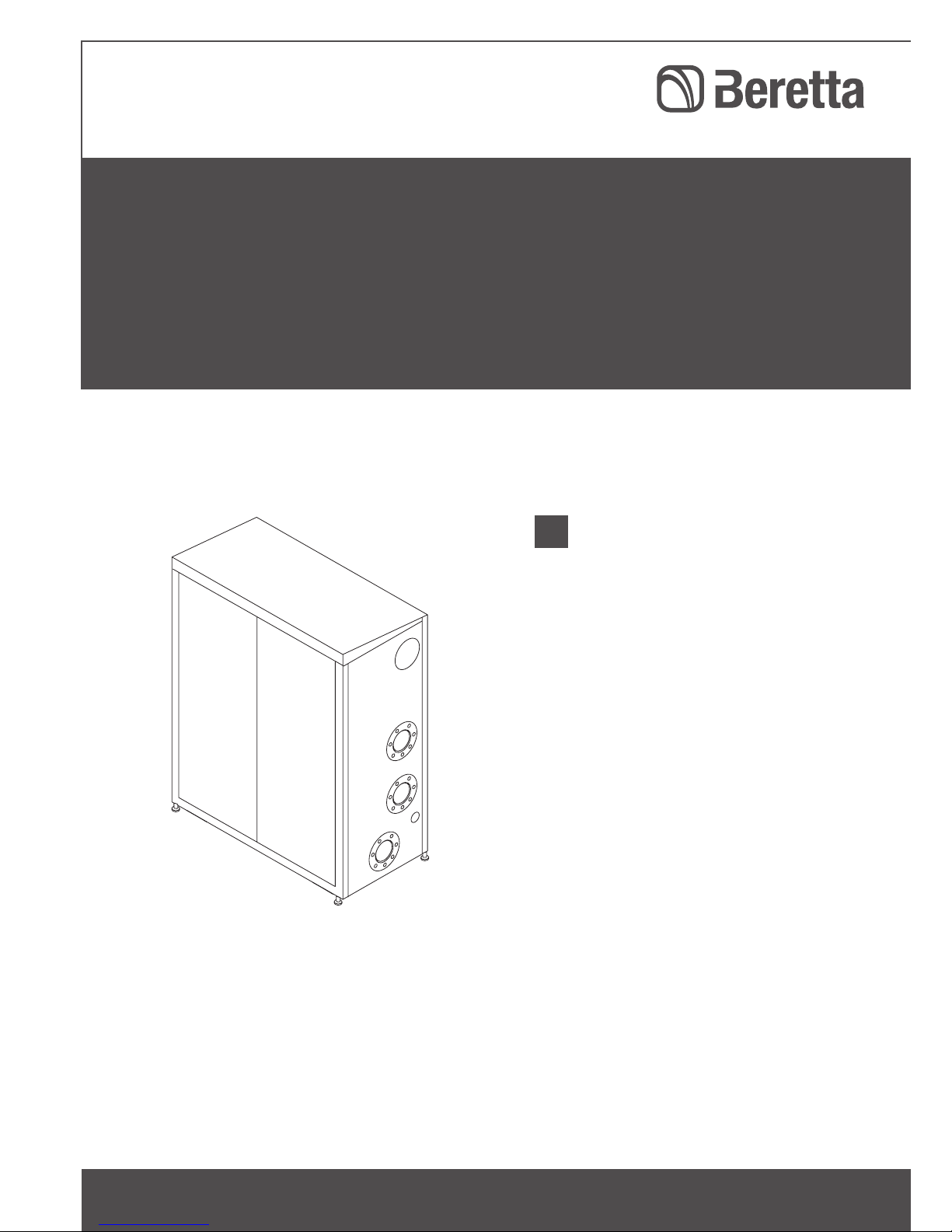
1.3 Description of the appliance
Power Plus Box
is a modular premixed condensing system
consisting of a set of 3 or 4 heating elements installed in
series.
Every
Power Plus Box
system is closed in a steel plate
containment structure made specifically for outdoor installation. The design was studied to ensure rational use
of space and to make it easier to access the components
during maintenance operations.
In addition to obtaining considerable fuel savings, due to
condensation,
Power Plus Box
systems offer the possibility
to avoid a central heating plant in installations where the
systems can be positioned outside or on the roof of the
building.

5
Depending on the model, the heat input (ref. PCI) of every
modular system reaches 110, 135 or 180 kW, and can be
modulated between 10% and 100%.
Efficiency reaches 107.7% (100% ref. PCI, 50°C-30°C) and
the low flue gas temperatures make it possible to use a fully
integrated plastic flue gas manifold.
The combustion system and the flue gas - water heat exchange make it possible to reach very high levels of combustion and heat to water transfer efficiency.
The gas/comburent air mixture is formed upstream of the
burner, due to the coupled modulating fan with a large
pressure difference, which intakes air from outside based
on the system's heat demand, as well as the pneumatic
regulator that supplies the quantity of gas required for optimal combustion based on the quantity of aspirated air.
The flue gas produced by combustion passes through the
numerous interspaces created by a winding with a bimetallic copper/steel corrugated coil that encounters a special cylindrical turbulator, which stops the free outflow and
constrains it to come into contact, in counter-current, with
the pipe in which the system return pipe passes.
By installing the individual heating elements in series not
only permits classical ignition rotation but can also be set
up so that when the first element reaches a certain power
percentage, the other subsequent elements will start already, all with the same load factor.
The modular systems can be cascade connected (up to
4), placing the antivibration couplings between the delivery, return and gas manifolds (accessories) and the
polypropylene coupling pipes for the ue gas manifold
and the condensate outlet manifold (supplied).
The ue gas evacuation and condensate outlet manifolds can have an outlet to the left or to the right.
Power Plus Box
150
Base module consisting of 3 heat generators for heating
and DHW production systems.
Heat input from 15 to
135 kW
Power Plus Box
200
Base module consisting of 4 heat generators for heating
and DHW production systems.
Heat input from 15 to
180 kW
.
1.4 Safety devices
The
Power Plus Box
modular system is equipped with the
following safety devices, installed on every heating element:
Safety thermostat
with automatic reset, which, when tripped
at 90°, shuts off the burner.
Hydraulic circuit diagnostics
the minimum flow rate of the
carrier fluid for every heating element is controlled by a
differential water pressure switch and an electronic safety
system that controls a delivery sensor and a return sensor.
The equipment is protected if there is no water or in the
case of insufficient circulation.
Safety valve
for the heating system pressure, which trips,
draining the system if circuit pressure exceeds the limit (5.4
bar).
Flue gas evacuation safety
the flue gas sensor, located at
the bottom of the exchanger, provokes a fault in the case
of high flue gas temperature (> 80°C). Furthermore, the
"check valve" present in the flue gas exhaust line prevents
the flue gas from passing between heating elements.
Fan safety
the fan speed is always monitored by a Hall-effect speed indicator device.
The
Power Plus Box
modulating systems are prepared for
cascade-coupling and this makes it possible to implement
compact and extremely flexible central heating plants
thanks to the system's modulating ratio.
b
The tripping of the safety devices indicates a potentially hazardous malfunction of the modular system,
therefore contact Technical Assistance Centre immediately.
Therefore it is possible to restart the system after waiting a
brief period (see the first start-up chapter).
6
a
The modular system must not be operated, even temporarily, if the safety devices are not functioning or
have been tampered with.
b
The safety devices must be replaced by Technical
Assistance Centre, only using original components
from the manufacturer. Refer to the spare parts catalogue provided with the modular system.
After making the repair, correct that the modular system is
operating properly.
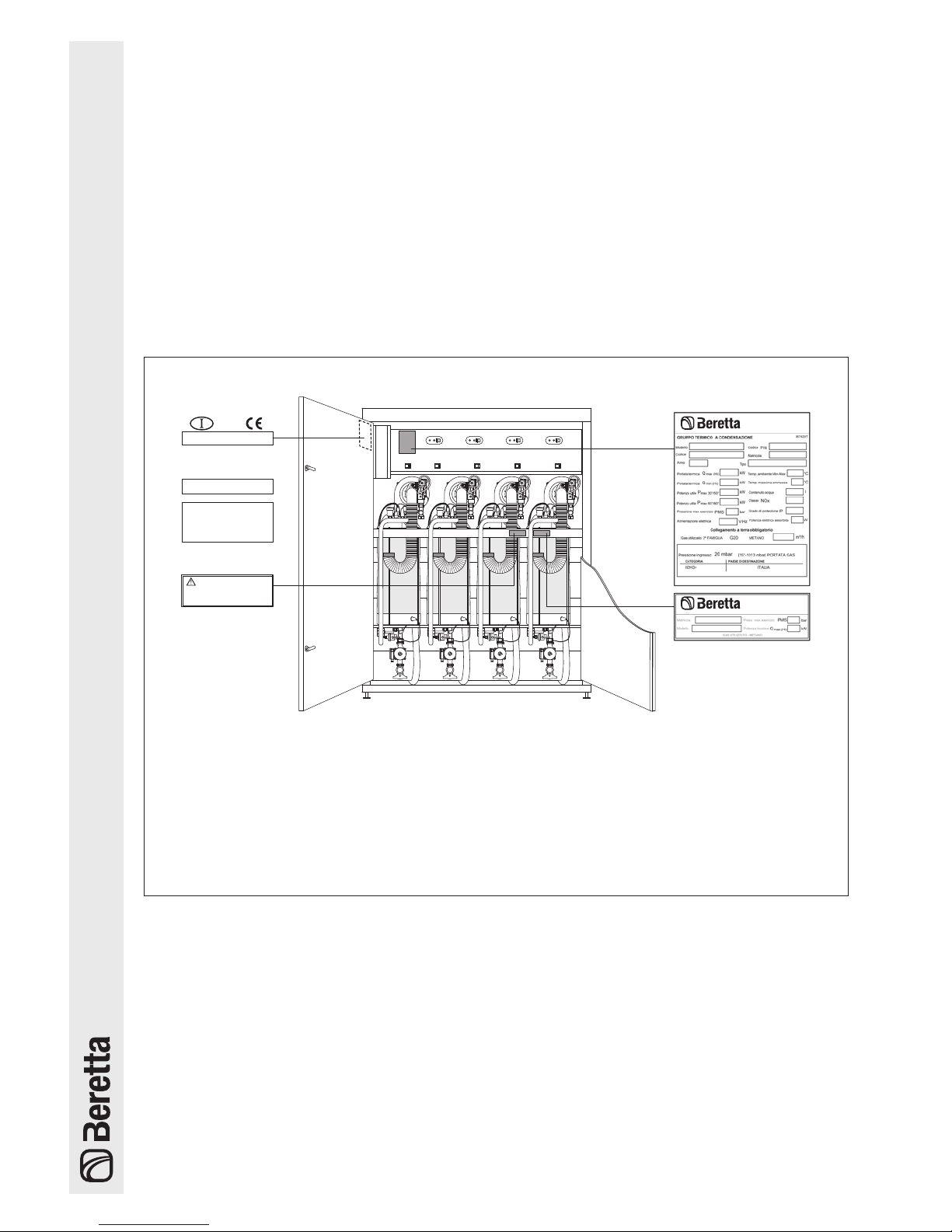
1.5 Identication
The products are identified by:
1
1
2
3
Caldaia regolata per:
G20 20 mbar
Paese di destinazione:
ITALIA
P
aese di destinazione:
Tipo di apparecchio
Caldaia categoria::
B23
II
2H3+
Pressioni di alimentazione gas:
Regolazione effettuata dal costruttore:
G20 - 20 mbar - 2H METANO
ATTENZIONE
Leggere attentamente il libretto istruzioni
prima di installare e mettere in servizio
l'apparecchio.
(Laterale DX
)
Temperatura ambiente:
min. -10°C max. 50°C
Questo apparecchio puó essere installato e
funzionare all'aperto o solo in locali
permanentemente ventilati secondo norma
UNI7129.
068411_E0
G20 20 mbar
G30 28-30 mbar
G31 37 mbar
1 Gas label
.
It is applied on the front part of the device and indicates the type of gas used by the modular system and the coun-
try of destination.
2 Technical data plate
It indicates the technical and performance data.
3 Serial number plate
This is located on the boiler body and specifies the serial number, model, and furnace power.
b
Spare parts and/or technical operation require the exact identication of the corresponding model. The absence of, tampering with or removing the identication plates or other does not make it possible to reliably identify the product, makes
any installation and maintenance operation dif
cult and invalidates the warranty.

7
1.6 System layout
1 2 3 54
6
7
9
8
11
12
10
18
19
20
13
14
22
21
23
24
16
15
25
26
27
28
17
1
Control panel
2
Single heating element
3
Control panel
4
Bus cable passage cable gland for the cascade
connection
5
Flue gas manifold
6
Gas manifold
7
System delivery manifold
8
Condensate drain manifold
9
System return manifold
10
Single heating element flue gas analysis outlet
11
Fan
12
Single heating element flue gas exhaust union
13
Automatic bleed valve
14
Safety thermostat
15
Drain cock
16
Manual diverting valve
17
Circulator (or 2-way valve)
18
Gas valve
19
Comburent air intake union
20
Gas cock
21
Flow probe
22
Ignition/detection electrode
23
Exchanger
24
Return probe
25
Exhaust flue probe
26
Differential water and minimum pressure switch
27
Return detection tap
28
Safety valve 5.4 bar

8
1.7 Coupling conguration
SZ2
VM
SB
PZ1
SZ1
COMPENSATORE
IDRAULICO
COMPENSATORE
IDRAULICO
50°C
30°C
80°C
60°C
SZ1
SZ2
VM
SB
PZ1
PB
SE
PB
SE
PZ2
PZ2
POWER PLUS BOX 200
POWER PLUS BOX 200POWER PLUS BOX 150
SZ1
Delivery manifold sensor
SZ2
Low system temperature sensor
SB
Boiler sensor
SE
Outdoor sensor
PZ1
Zone 1 circulator (high temperature)
PZ2
Zone 2 circulator (low temperature)
PB
Boiler circulator
VM
Mixer valve
NOTE: it is possible to couple up to a maximum of 4
Power Plus Box
with a cascade connection.

9
1.8 Technical specications
MODEL
Power Plus Box
150 200
Fuel G20 - G30 - G31
Device category II2H3+
Device type B23, B53
Furnace heat output ref. PCS (min - max) 16,0 - 150 16,0 - 200 kW
Furnace heat output ref. PCI (min - max) 14,4 - 134,9 14,4 - 179,8 kW
Useful heat output (80°/60°C) 132,5 176,6 kW
Useful heat output (50°/30°C) 145,3 193,6 kW
Useful heat output (60°/40°C) 143,1 190,8 kW
Useful efficiency ref. PCI (80°C/60°C) 98,2 %
Useful efficiency ref. PCI (50°C/30°C) 107,7 %
Useful efficiency ref. PCI Tm=50°C (60°C/40°C) 106,1 %
Useful efficiency at 30% ref. PCI (80°C/60°C) 98,7 %
Useful efficiency at 30% ref. PCI (50°C/30°C) 108,7 %
Useful efficiency at 30% ref. PCI Tm=50°C (60°C/40°C) 106,6 %
Chimney loss with burner operating 1,3 %
Chimney loss with burner off 0,1 %
Casing loss (Tm=70°C) 0,5 %
Flue gas temperature Return temperature + 5 °C °C
CO2 at minimum 9,0 (G20) - 10,4 (G30-31) %
CO2 at maximum 9,0 (G20) - 10,4 (G30-31) %
CO S.A. at minimum - maximum less than 11 - 91 mg/kWh
NOx Class 5
Maximum heating operating pressure 6 bar
Maximum permitted temperature 90 °C
Boiler water temperature selection range (± 3°C) 20 - 80 °C
Water capacity 15 20 l
Power supply 230~50/60 V~Hz
Maximum electric power consumption 684 912 W
Electric degree of protection X4D IP
Quantity of condensate at maximum power 21,6 28,8 kg/h
CONNECTIONS
Delivery manifold 5" DN 125 - PN 6 Ø - DN
Return manifold 5" DN 125 - PN 6 Ø - DN
Gas manifold 3" DN 80 - PN 6 Ø - DN
Flue gas outlet 160 Ø mm
Condensate outlet 50 Ø mm
DIMENSIONS
Height 1500 mm
Width 1250 mm
Depth 650 mm
10
Detail
Power Plus Box
150 200
Maximum rated heat input 150 200 kW
Minimum rated heat input 16,7 16,7 kW
Domestic hot water maximum rated thermal input (80-60) - - kW
Domestic hot water minimum rated thermal input (80-60) - - kW
PARAMETER
Seasonal heating energy efficiency class - Water heating energy efficiency class - Rated input Prated 132,6 176,8 kW
Seasonal energy efficiency in central heating mode
ηs
92,5 92,5 %
USEFUL HEAT OUTPUT
at rated thermal input and at high temperature rating P4 132,6 176,8 kW
at 30% of rated thermal input and at low temperature rating P1 48,9 65,1 kW
EFFICIENCY
at rated thermal input and at high temperature rating
η4
88,4 88,4 %
at 30% of rated thermal input and at low temperature rating
η1
97,8 97,8 %
ADDITIONAL ENERGY CONSUMPTION
at full load El max 240 320 W
at partial load El min 72 96 W
in stand-by PSB 6 8 W
OTHER PARAMETERS
Heat loss in standby mode Pstby 1326 1768 W
Energy consumption of the pilot light Ping - - W
Annual energy consumption Q HE - - GJ
Level of inner sound power LWA - - dB
Emissions of nitrogen oxides NOx - - mg/kWh
FOR COMBINATION HEATING APPLIANCES
Declared load profile - Energy efficiency in DHW mode
ηWH
- - %
Daily electrical energy consumption Qelec - - kWh
Daily fuel consumption Qfuel - - kWh
Annual electrical energy consumption AEC - - kWh
Annual fuel consumption AFC - - GJ

11
1.9 Water circuit
RI
GAS
SC
SF
AA
1
MI
AA AA
2
3
4
8
9
6
5
7
12
1014
11
13 13
1
Fan
2
Automatic bleed valve
3
Burner
4
Heat exchanger
5
Drain cock
6
Differential water and minimum pressure switch
7
Circulator (or 2-way valve)
8
Gas valve
9
Flue gas exhaust union with check valve and flue gas
analysis outlet
10
Manual diverting valve
11
Return shut-off valve
12
Gas cock
13
Delivery sensor traps
14
Safety valve
AA
Air inlet
SF
Exhaust flue duct
SC
Condensate outlet
MI
Central heating flow
RI
Central heating return
GAS
Gas supply

12
WATER SIDE PRESSURE DROP FOR EVERY HEATING ELEMENT
Every heating element of the
Power Plus Box
modular system is equipped with a circulator, whose performance curve is
provided below, in reference to speed 3.
0
Pressure drop (mbar)
Flow rate (l/h)
1200
1100
1000
900
800
700
600
500
400
300
200
100
500
1000 1500 2000 2500 3000 3500 4000
Pressure lost by
the fluid when
crossing the
heating element
P available for
system circulation
1 heating element
Circulator characteristic
curve
Heating element pressure drop at 2000 l/h: 550 mbar.
Flow rate necessary for every heating element: 2000 l/h.
b
At the first start-up, and at least once a year, the rotation of the circulator shaft should be checked as, especially after long periods of not being operated, deposits and/or residuals could impede its free rotation.
b
Before loosening or removing the circulator cap, protect the electric devices located underneath from any
water that exits.
a
It is prohibited to operate the circulators without water.

13
1.10 Location of sensors
SZ1
Delivery manifold sensor
SZ2
Low system temperature sensor
SB
Boiler sensor
SE
Outdoor sensor
PZ1
Zone 1 circulator (high temperature)
PZ2
Zone 2 circulator (low temperature)
PB
Boiler circulator
VM
Mixer valve
HEATING
DELIVERY SENSOR
HEATING RETURN
SENSOR
FLUE GAS
SENSOR
(triggering at 80°C)
SAFETY
THERMOSTAT
(triggering at 90°C)
HYDRAULIC
COMPENSATOR
50°C
30°C
80°C
60°C
SZ1
SZ2
VM
SB
PZ1
PB
SE
PZ2
POWER PLUS BOX
b
Install sensors SZ2 and SB in a trap (outside the modular system).
Correspondence table for all sensors
Measured temperatures (°C) - Resistive values of the sensors (Ω).
T (°C)
R (°Ω)
T (°C)
R (°Ω)
T (°C)
R (°Ω)
T (°C)
R (°Ω)
T (°C)
R (°Ω)
T (°C)
R (°Ω)
T (°C)
R (°Ω)
- 20 67739 - 1 28481 18 13062 37 6470 56 3426 75 1925 94 1137
- 19 64571 0 27279 19 12565 38 6247 57 3319 76 1870 95 1108
- 18 61568 1 26135 20 12090 39 6033 58 3216 77 1817 96 1079
- 17 58719 2 25044 21 11634 40 5828 59 3116 78 1766 97 1051
- 16 56016 3 24004 22 11199 41 5630 60 3021 79 1717 98 1024
- 15 53452 4 23014 23 10781 42 5440 61 2928 80 1669 99 998
- 14 51018 5 22069 24 10382 43 5258 62 2839 81 1622 100 973
- 13 48707 6 21168 25 9999 44 5082 63 2753 82 1577 101 948
- 12 46513 7 20309 26 9633 45 4913 64 2669 83 1534 102 925
- 11 44429 8 19489 27 9281 46 4751 65 2589 84 1491 103 901
- 10 42449 9 18706 28 8945 47 4595 66 2512 85 1451 104 879
- 9 40568 10 17959 29 8622 48 4444 67 2437 86 1411 105 857
- 8 38780 11 17245 30 8313 49 4300 68 2365 87 1373 106 836
- 7 37079 12 16563 31 8016 50 4161 69 2296 88 1336 107 815
- 6 35463 13 15912 32 7731 51 4026 70 2229 89 1300 108 796
- 5 33925 14 15289 33 7458 52 3897 71 2164 90 1266 109 776
- 4 32461 15 14694 34 7196 53 3773 72 2101 91 1232 110 757
- 3 31069 16 14126 35 6944 54 3653 73 2040 92 1199
- 2 29743 17 13582 36 6702 55 3538 74 1982 93 1168
14
1.11 Wiring diagrams
gv
J15
4
321
J2
5
m
m
a
a
5
6
J14
J6
gv
gv
J8
3
Fusibile 4A
F1
Terra
Circolatore
Fase
Neutro
Terra
Terra
Ground star pole
gv
Terra
Neutro
Ground star pole
Fase
a
a
a
m
m
m
1
T1
1
gv
J7
al polo stella di terra
g
n
v
b
m
2
4
3
13
45
66
7
J1
a
m
m
a
8
7
J12
n
1
4
3
2
5
b
m
v
g
m
6
5
4
m
a
11
12
21
J11
NTC mandata
NTC di ritorno
Alimentaz. Sens. Hall
Soffiante (-)
Input Sens. Hall
Soffiante (+)
Comune Sens. Hall
Termostato limite
Valvola gas
2
13
a
9
m
J16
NTC fumi
J9
J4
a
10
WD
J5
T3
PC
Main
2
1
1
2
gv
Bus line with female connector for
possible connection to another
slave card for an adjacent
modular system.
230V~50Hz
SLAVE 1
IG1
C
TS
VG
SM
SR
SF
EA/ER
J10
J17
BUS 1
A
B
IG
a
m
13
Pressostato Diff.
PD
CS
Connection by the installer
15
Bus
16
Com.
87
2
1
231
J9
232221
Valv.Mix
OFF
0
20
Alarm
ON
1
18
19
J8
9
17
24V
7
6
8
1314
Input
Analogic
NTC
Circ. 2
10 9
7
6
8
12
Circ.2
11
56
J12
4321
6
234
5
J10
28
27
Pump
252426
Pump 3
Pump
1
254
3
J11
NTC
1
2
NTC
NTC
453
Off - Valv. Mix
a
m
gv
gv
gv
gv
Neutro 230V a.c.
F
ase 230V a.c.
Terra
Terra
Terra
Terra
Fase Pompa circ.1
Neutro Pompa circ.1
Fase Pompa Sanit.
Neutro Pompa Sanit.
Neutro Valv. Mix
Fase Pompa 3
Neutro Pompa 3
J4
J2
J8
J10
R4
2
3
J3
J6
J5
J7
F1
Fuse
3.15 A
1
R6
R5
MC
R3 R2
On - Valv. Mix
Alarm
Comune
J12
2
BUS J14
1
R1
4
3
T1
Ebus contr. remoto
24V contr. remoto
Comune
Analogic Input
Comune
T. A. circ. 1
Comune
T. A. circ. 2
2
Comune
4
J1
PC
BARCODE
NTC climatica
J11 11
Comune
NTC mand. circ. 2
NTC mand. circ. 1
Comune
Comune
NTC bollitore
Comune
MASTER
PB
PZ1
PZ2
VM
SZ1
SB
SE
SZ2
TA1TA2
J11 4
J11 12
J11 5
J11 13
J11 6
J11 14
J11 7
J11 7
J11 14
J11 6
J11 13
J11 5
J11 12
J11
4
J11 11
IACR
J11 3
J11 10
J12 2
J12 3
J12 4
J12 4
J12 3
J12 2
J11
8
J11
1
J11
9
J11
2
J11
10
J11
3
J10 6
J10
5
J10
4
J10
3
J10
2
J10
1
J8
5
J8
4
J8
3
J8
2
J8
1
J10 6
J10 5
J10 4
J10 3
J10 2
J10 1
J9 3
J9 2
J9 1
J8 2
J8 1
1
3
7
14
1
8
J11
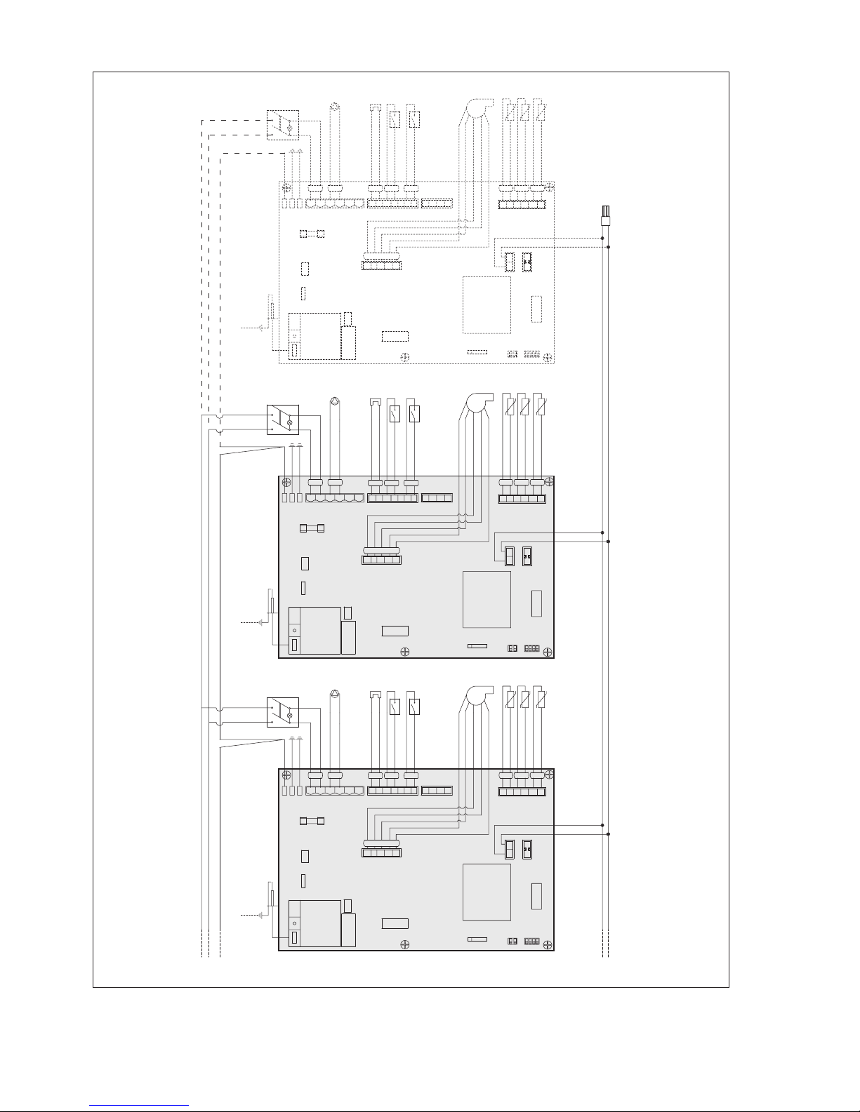
MODULAR SYSTEM
IG
Modular system main switch
CS
Contact for external safeties
PB
Boiler circulator
PZ1
Zone 1 circulator (high temperature)
PZ2
Zone 2 circulator (low temperature)
VM
Mixer valve
CR
Remote control (accessory available separately)
IA
Analogue input
SB
Boiler sensor
SZ1
Zone 1 sensor
SZ2
Zone 2 sensor
SE
Outdoor sensor
TA1
Zone 1 room thermostat (high temperature)
TA2
Zone 2 room thermostat (low temperature)
HEATING ELEMENT
C
Heating element circulator (or 2-way valve)
SM
Flow probe
SR
Return probe
SF
Exhaust flue probe
TS
Safety thermostat
VG
Gas valve
PD
Water differential pressure switch
EA/ER
Ignition/detection electrode
IG1..IG4
FIRST...FOURTH heating element switch
J10/J17
Addressing microswitches
15
A
BUS 2
BUS 3
BUS 4
gv
J15
4
321
J2
5
m
m
a
a
5
6
J14
J6
gv
gv
J8
3
Fusibile 4A
F1
Terra
Fase
Neutro
Terra
Terra
1
T1
1
J7
al polo stella di terra
g
n
v
b
m
2
4
3
13
45
66
7
J1
a
m
m
a
8
7
J12
n
1
4
3
2
5
b
m
v
g
m
6
5
4
m
a
11
12
21
J11
NTC mandata
NTC di ritorno
Alimentaz. Sens. Hall
Soffiante (-)
Input Sens. Hall
Soffiante (+)
Comune Sens. Hall
Termostato limite
Valvola gas
213
a
9
m
J16
NTC fumi
J9
J4
a
10
WD
J5
T3
PC
Main
SLAVE 2
IG2
TS
VG
SM
SR
SF
EA/ER
J10
J17
a
m
13
Pressostato Diff.
PD
gv
J15
4
321
J2
5
m
m
a
a
5
6
J14
J6
gv
gv
J8
3
Fusibile 4A
F1
Terra
Fase
Neutro
Terra
Terra
1
T1
1
J7
al polo stella di terra
g
n
v
b
m
2
4
3
13
45
66
7
J1
a
m
m
a
8
7
J12
n
1
4
3
2
5
b
m
v
g
m
6
5
4
m
a
11
12
21
J11
NTC mandata
NTC di ritorno
Alimentaz. Sens. Hall
Soffiante (-)
Input Sens. Hall
Soffiante (+)
Comune Sens. Hall
Termostato limite
Valvola gas
213
a
9
m
J16
NTC fumi
J9
J4
a
10
WD
J5
T3
PC
Main
SLAVE 3
IG3
C
TS
VG
SM
SR
SF
EA/ER
J10
J17
a
m
13
Pressostato Diff.
PD
gv
J15
4
321
J2
5
m
m
a
a
5
6
J14
J6
gv
gv
J8
3
Fusibile 4A
F1
Terra
Fase
Neutro
Terra
Terra
1
T1
1
J7
al polo stella di terra
g
n
v
b
m
2
4
3
13
45
66
7
J1
a
m
m
a
8
7
J12
n
1
4
3
2
5
b
m
v
g
m
6
5
4
m
a
11
12
21
J11
NTC mandata
NTC di ritorno
Alimentaz. Sens. Hall
Soffiante (-)
Input Sens. Hall
Soffiante (+)
Comune Sens. Hall
Termostato limite
Valvola gas
213
a
9
m
J16
NTC fumi
J9
J4
a
10
WD
J5
T3
PC
Main
SLAVE 4
IG4
C
TS
VG
SM
SR
SF
EA/ER
J10
J17
a
m
13
Pressostato Diff.
PD
Circolatore
C
Circolatore Circolatore
Bus line with male
connector for possible
connection to another slave card
for an adjacent modular system.
b
The circulators must be connected with the interposition of suitable contactors with manual emergency actuation.
16
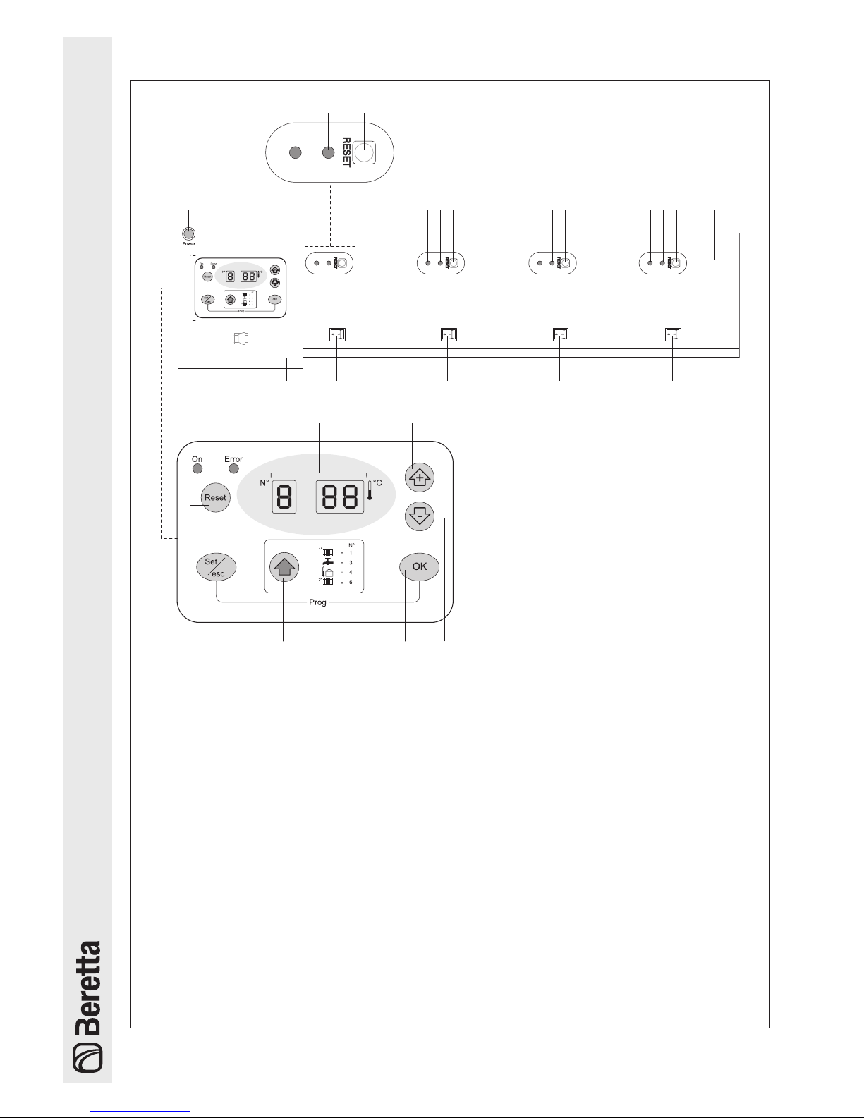
1.12 Control panels
1 2 4 5 6 4 5 6 4 5 6
812 91011
7
13
14 15 16 17
1819202122
4 5 6
3
1
Electric power supply signal
2
Master user interface
3
Slave user interface
4
Slave card operating status signal:
- FLASHES in absence of heat demand
- FLASHES QUICKLY during the ignition cycle
- ON in presence of a flame
5
Single heating element block signalling:
- OFF in absence of errors
- FLASHES QUICKLY in case of errors that can be
deactivated automatically
- ON in case of permanent errors
6
Single heating element slave reset button
7
Instrument panel
8
FOURTH heating element switch (only for
Power Plus
Box
200)
9
THIRD heating element switch
10
SECOND heating element switch
11
FIRST heating element switch
12
Main control panel
13
Modular system main switch (only accessible by
turning the main control panel)
14
Electric power supply signal
15
Modular system block signal
16
Display
17
Value increase button
18
Value decrease button
19
Save button
20
Parameter selection button
21
Operating mode selection button
22
Master reset button

17
Functional notes
The
Power Plus Box
modular system control panel manag-
es:
- The DHW priority function which, in the case of a
DHW demand, the master card can also serve the
high or low temperature circuit.
- The anti-freeze function, also active in stand-by mode,
which starts the high temperature circuit circulator
and the loop circulator if the manifold temperature
drops below 5°C. If there is an outdoor sensor, the
circulators turn on if the outdoor temperature drops
below 3°C. If after 10 minutes the manifold temperature is less than 5°C, a burner turns on at maximum
power until the manifold temperature reaches 20°C.
If after 10 minutes the manifold temperature exceeds
5°C but the outdoor temperature is lower than 3°C the
circulators remain active until the outdoor temperature goes above that value.
- The cascade management function: to manage the
power delivered by the system, it is possible to select between the minimum and maximum quantity of
lit burners.
- The exhaust function: the high and low temperature
circuit pumps remain in operation for 5 minutes after
the last burner is turned off. The waiting time before
the heating element circulator is stopped once the
burner is shut off is 6 minutes. When the last burner
is turned off, the circulator only stops when the room
thermostat demand stops.
- The ignition/shut-off control function: in both cascading management modes there is a burner ignition and
shut-off limitation function in the case of low heat demand.
- The system anti-freeze protection function: the
Pow-
er Plus Box
condensing systems are equipped with
freeze protection electronics. The electronics activate
the heating unit if the temperature drops below the
minimum threshold. Therefore the use of particular
anti-freeze fluids are not necessary except in the
case of uses with the equipment completely shut off
for long periods. If using anti-freeze fluids make sure
they are not aggressive for steel.
1.13 User interface (master)
The
Power Plus Box
system control panel buttons have different functions depending on the mode. For example, a combination of two buttons corresponds to a single function. Or a function is activated by pressing the button briefly or waiting
approx. 5 seconds.
Reset
Serves to release the electric board after a permanent arrest
Set/esc
Set
: makes is possible to enter the parameter change mode
and monitor mode for the single units
This is used to view the operating status of the various circuits managed by the Master card
and
Are used to increase or decrease a certain value
OK
Press to memorize new values
18
1.13.1 Display mode
The red (error) LED turns on in the case of faults that involve the permanent block of a heating element (normal operation
can be reset by pressing the Master or Slave reset button).
The green (on) LED indicates the presence of the electric power supply.
The 3 digits with seven segments display the system statuses:
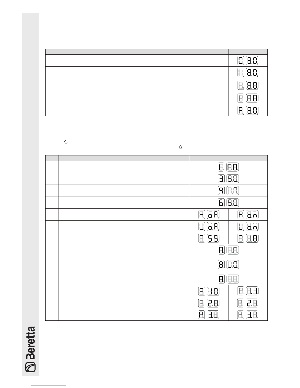
SYSTEM STATUS DISPLAY
No demand for heating or hot water.
The two right hand digits display flow temperature T1. E.g. T1 = 30°C
Demand for 1st system or 1st and 2nd system simultaneously.
The two right hand digits display flow temperature T1. E.g. T1 = 80°C
Demand for hot water or simultaneous functioning.
The two right hand digits display flow temperature T1. E.g. T1 = 80°C
The point after the first digit flashes.
Demand for 2nd system.
The two right hand digits display flow temperature T1. E.g. T1 = 80°C
Antifreeze function
1.13.2 Display mode
Temperature values and operating status of the various circuits
Press the button to scroll forward and view the values set for the individual circuits.
The values listed below will be displayed in succession by pressing the button.
POS. VISUALIZED VALUES DISPLAY
1
Manifold delivery temperature T1
(e.g. T1 = 80°C)
2
Hot water T3
(e.g. water tank temp. = 50°C)
3
Outside temperature T4
(e.g. T4 = 7°C)
4 Flow temperature 2nd system or low T6 system
5
1st system room thermostat off or on
(e.g. OFF = contact open; ON = contact closed)
6
2nd system room thermostat off or on
(e.g. OFF = contact open; ON = contact closed)
7
0-10V analogue input
(e.g. 5.5V ; 10V respectively)
8
Mixer valve function status
(e.g. closing, opening, pause)
9
Principal circulator function status.
(e.g. circulator OFF; circulator ON respectively)
10
Function status hot water system circulator.
(e.g. circulator OFF; circulator ON respectively)
11
Second circulator function status
(e.g. circulator OFF; circulator ON respectively)
To exit the value display, press the
"OK"
button.
If no operation is performed within 5 minutes, the card will automatically return to display mode.
 Loading...