

Beretta Power Plus Box 1003 P EXT, Power Plus Box 1004 P INT, Power Plus Box 1003 P INT, Power Plus Box 1004 P EXT, Power Plus Box 1002 P INT ERP Installation Manual
...
Installation Manual
Power Plus Box 1002-1003-1004 P INT-EXT
CONDENSING
Installation Manual
EN
RANGE
CONTENTS
2
MODEL CODE
Power Plus Box 1002 P INT 20067829
Power Plus Box 1003 P INT 20067830
Power Plus Box 1004 P INT 20067831
Power Plus Box 1002 P EXT 20067832
Power Plus Box 1003 P EXT 20067833
Power Plus Box 1004 P EXT 20067834
Power Plus Box 1002 P INT ERP 20107464
Power Plus Box 1003 P INT ERP 20107472
Power Plus Box 1004 P INT ERP 20107478
Power Plus Box 1002 P EXT ERP 20107469
Power Plus Box 1003 P EXT ERP 20107477
Power Plus Box 1004 P EXT ERP 20107479
CERTIFIED COMPANY
UNI EN ISO 9001:2008
UNI EN ISO 14001:2004
1 GENERAL INFORMATION ................3
2 WARNINGS............................3
3 TECHNICAL FEATURES .................4
3.1 Main features ............................4
3.2 Advantages.............................. 5
3.3 Safety devices............................ 5
3.4 Components ............................. 5
4 INSTALLATION.........................8
4.1 Product packaging and identification.......... 8
4.2 Installation premises ....................... 8
4.3 Water connections ........................9
4.4 System cleaning and water treatment..........9
4.5 Positioning and preparation for installation...... 9
4.6 Condensate outlet........................ 10
4.7 Water circuit ............................10
4.8 Exhaust flue............................. 10
5 INSTALLATION DIAGRAMS .............11
6 ELECTRICAL SYSTEM .................12
6.1 Power supply ........................... 12
6.2 Electrical connections..................... 12
6.2.1 Connection to mains ...................... 12
6.2.2 Master board connection ..................13
6.2.3 Connection to thermoregulators .............14
6.2.4 Connection to pumps ..................... 14
6.2.5 Connection to room thermostats (on/off) ......14
6.2.6 Connection to weather temperature probe..... 14
6.2.7 Frost protection .......................... 16
6.2.8 Connection to 0-10v external thermoregulator ..16
6.2.9 Connection to alarm device ................ 16
6.2.10 Remote control .......................... 16
6.3 Emergency mode ........................ 16
6.4 Cascade installation ...................... 17
6.4.1 Connection to mains ...................... 17
6.4.2 Serial Connection (BUS) ................... 17
6.5 Position of the flow probe ..................17
This manual, Code
- Rev.
comprises
pages.
ENGLISH
The following symbols are used in this manual:
b
CAUTION! =
and adequate preparation.
a
STOP! =
Identifies actions that require caution
Identifies actions that you MUST NOT do.
7 FIRST OPERATING ....................18
7.1 Slave board setting ....................... 18
7.1.1 Example of configuretion of a battery with 7 burner
in cascade ............................. 18
7.2 Gas valve calibration ..................... 19
8 USE AND ADJUSTMENT ................20
8.1 Control panel: description.................. 20
8.2 Display mode ........................... 21
8.3 Display mode ........................... 21
8.4 Changing the user parameters .............. 22
8.5 Monitor mode ........................... 22
8.6 Installer programming mode................ 23
8.7 Test mode .............................. 24
8.8 Error mode .............................24
8.9 Permanent block ......................... 24
9 SETTING FUNCTIONING PARAMETERS ...25
9.1 Setting the heating parameters.............. 25
9.2 Setting the DHW parameters ............... 26
9.3 Heat control setting....................... 27
10 LIST OF PARAMETERS .................32
11 ERROR LIST ..........................34
11.1 Master board errors ......................34
11.2 Slave board errors........................34
12 WIRING DIAGRAMS....................36
13 TECHNICAL SPECIFICATIONS ...........38
14 WATER IN CENTRAL HEATING SYSTEMS . 40
This manual, Code 20074299 - Rev. 6 (02/18) comprises 44 pages.

1 GENERAL INFORMATION
Dear Customer,
congratulations on your choice and thank you for placing
your confidence in our products. With
EXT
you have chosen technology that is the very essence
of energy saving and functionality.
Moreover, all B products conform to the strictest directives and European standards in force.
This product was produced, amongst others, in conformity
to the following directives and standards:
- Gas Appliances Directive 2009/142/EC (until 20 April
2018) and Regulation (EU) 2016/426 (from 21 April 2018)
- Directive 92/42/EEC on efficiency requirements and
Annex E and Pres. Republic Decree n. 412, 26 August 1993 (****)
- Electromagnetic Compatibility Directive 2014/30/EU
- Low Voltage Directive 2014/35/EU
- Ecodesign Directive 2009/125/CE for energy-related
products
- Delegated Regulation (EU) N. 813/2013
N 15417 Gas-fired central heating boilers - Specific re-
- E
quirements for condensing boilers with a nominal heat
input greater than 70 kW but not exceeding 1000 kW
- EN 13836 Gas fired central heating boilers - Type B
boilers of nominal heat input exceeding 300 kW, but
not exceeding 1000 kW.
The
Power Plus Box P INT-EXT
moreover conform to the regulatory provisions pursuant to
the INAIL “R” File, section R.3.B.
B has been certified with UNI EN ISO 9001/2000 since
22.07.2004.
Power Plus Box P INT-EXT
to its credit:
- European Conformity Mark (based on Directive
92/42/CEE) issued by the authorized German certification organization ;
- Maximum energy efficiency class (according to Directive 92/42/EEC) identified by the symbol ****;
- Classified in the strictest class for nitrogen oxide-related pollution (fifth grade according to UNI EN 297)
- Patented heat exchanger.
condensing modular systems
is furthermore a product having
Power Plus Box P INT-
2 WARNINGS
b
The heating unit must be used for the purpose for
which it was specifically designed and produced.
Any whatsoever contractual or extra-contractual liabilities for damages caused to persons, animals or
objects due to errors in installation, adjustment, maintenance and improper usage are to be excluded.
b
Installation must fully comply with provisions of the law
in force and instructions provided by the manufacturer
to ensure safety and correct functioning, always calling upon professionally qualified technical personnel
who will issue the declaration of conformity for the
installation accomplished with good workmanship,
in compliance to regulatory provisions in force and
guidelines given in this handbook. The appliance must
be installed in appropriate premises and together with
the specific systems installed according to the law.
b
Commissioning will be carried out by personnel from
the authorized Technical Assistance Centre only and
within 8 days from when the appliance was installed.
After initial ignition the Technical Assistance Centre
will fill in the warranty certificate, leaving the user their
part to be kept, marking the beginning of the period
of guarantee at the terms and conditions specified on
the relative slip.The appliance in its original packing
may be exposed to temperatures between 4°C and
40°C. Do not expose the appliance to bad weather
conditions after it has been unpacked, anyhow to
temperatures below 4°C or above 40°C until it has
been connected up to the water, gas and electricity
mains so as to be able to activate the frost protection
systems described in paragraph 6.2.7.
b
Check that the product is complete, undamaged and
as ordered as soon as you receive it. Report any discrepancies or damage to the
it.
b
In case of leaks, disconnect the heating unit from the
mains, close the water from the mains and promptly
contact the Technical Assistance Centre.
b
Regularly check that the condensate drain is free
from obstruction.
b
Regularly check that the working pressure of the water circulation system, when cold, is below the maximum limit specified for the appliance. If not, contact
the Technical Assistance Centre.
b
Maintenance jobs on the heating unit must be carried out by personnel from the authorized Technical
Assistance Centre. Maintenance must be performed
at least once a year. Correct maintenance is essential
for safety as well as for the efficiency and long working life of the product. Proper maintenance keeps
consumption and emissions down, and ensures that
the product continues to operate reliably over time.
Analyse the combustion fumes before commencing
maintenance. The results of fume analysis can give
a clear idea of what servicing or repairs are needed.
b
We recommend cleaning inside the exchanger once
a year, extracting jet and burner and removing any
installation debris by suction. This operation will be
done by personnel from the Technical Assistance
Centre only.
b
The warranty slip endorsed during the course of commissioning will have to be produced for any servicing
required during the guarantee period. The manufacturer shall not be held liable for any damages caused
by mishandling, improper use or errors in installation,
use and maintenance work on the appliance. In the
event of breakdown or malfunction switch off the appliance, avoiding to make any attempt to repair it and
contact the Technical Assistance Centre.
b
This manual must be read carefully for the boiler to be
used rationally and safely, and must be kept with care
so as to be on hand where required by the technician
or installer, to facilitate the appropriate installation,
running and maintenance of the boiler. B will not
be held liable for any translations possibly giving rise
to wrong interpretation. This manual is an integral part
of the heating unit and must consequently be kept
with care and must ALWAYS accompany the boiler
even when passed on to another owner or user or
transferred to another installation. Ask the Technical
Assistance Centre for another copy if it should be lost
or damaged.
B dealer who sold
3

a
Children and people with disabilities or without experience and specific knowledge are forbidden to use
the heating unit unless they are assisted by a qualified person responsible for their safety.It is forbidden to use electrical devices or equipment, such as
switches, appliances, etc. if there is a smell of gas or
un-burnt products. If so:
- ventilate the room, opening doors and windows;
- close the gas valve at the mains;
- immediately call in the Technical Assistance Centre
or professionally qualified personnel.
a
It is forbidden to touch the heating unit with bare feet
or parts of the body wet.
a
It is forbidden to start on any technical or cleaning
jobs before disconnecting the heating unit from the
power mains.
a
It is forbidden to alter the safety and adjustment devices without permission and instructions from the
heating unit manufacturer.
a
It is forbidden to obstruct the condensate drain.
a
It is forbidden to pull, detach, twist the wiring coming
out of the heating unit, even if unplugged from the
power supply.
a
It is forbidden to obstruct or reduce the size of air
vents.
a
It is forbidden to expose the boiler to atmospheric
agents (if it is not a specific unit for outdoors).
a
It is forbidden to leave containers or flammable substances in the premises where the boiler is installed.
3 TECHNICAL FEATURES
3.1 Main features
Power Plus Box P INT-EXT
mixed, blown, thermal group; it is made up of a series of
Power Plus Box P INT-EXT
tery.
A unit is made of N° 2, 3 or 4 heat exchangers, each with
a modulating power from 23 ti 115 kW; equipped with climatic regulation and RS485 connection. Each device can
be serially matched up with same tipe units up to a total
installed power of 3680 kW (eight
equal to a total of di 32 heat exchangers).
b
In case of installation of more than 32 unit (up to 60
unit) please contact
tre.
It is possible to connect up two thermal groups (with a total
of 8 heat exchangers) directly using the internal 5” hydraulic manifolds and the internal 3” gas manifold.
The efficiency of the generators reaches 109% based on
the lower heat potential of natural gas (Hi) making it possible to use a flue manifold entirely made of plastic (PP). The
system also enables continual modulation of the gas and
combustion air flow.
The
Power Plus Box P INT-EXT
as far as operating costs (up to 109% efficiency per Hi, see
Figure 1) reliability and flexibility. In fact, thanks to the new
heat exchanger with improved power, to the new electronic
management, to the modularity and versatility, it is possible
to make a rapid connection to any kind of heating system
and storage hot water production.
is a condensing, modular, pre-
thermal elements installed in bat-
Power Plus Box P INT-EXT
B Technical Assistance Cen-
heating unit is the optimum
4
a
Do not dispose of packaging material into the environment, or leave it within the reach of children, since
it can become a potential hazard. Dispose of packaging material in compliance with applicable legislation.
a
The user is forbidden to open the cupboard containing the heating unit. Any jobs on the inside of the latter must be done by the Technical Assistance Centre
or by qualified personnel.
a
It is forbidden to discard the product as household
waste. At the end of its service life, it can be consigned to specific selected waste centres provided
by the local authorities or else to dealers providing
this service. Disposing of a domestic appliance separately will prevent possible harmful consequences
for environment and health derived from inappropriate disposal, likewise making it possible to recuperate the materials it is made of with substantial savings
in energy and resources.
Figure 1
The insertion of a single thermal element in cascade, over
the traditional rotation of the ignition, can take place with
variable factor of heating power load
tain power percentage of the first element is reached (e.g.
30%), the successive element already starts with the same
load factor. This latter feature allows to share the power
supplied inside more than one heat exchangers with a
power/exchange surface ratio which is particularly favourable for condensation latent heat.
, so that when a cer-

3.2 Advantages
- Totally pre-mixed micro-flame jet burner;
- condensing stainless steel exchanger, with efficiency
up to 109% (see Figure 1);
- power from 23 to 115 kW ;
- possibility to manage 32 thermal units (burners) in series for a maximum power of 3680 kW;
- maximum exhaust flue exit temperature 80°C;
- plastic flue manifold in PP self-extinguishing (see par
4.8):
- water manifold, condensate and smoke manifold inside the boiler;
- quick connection of both water, condensate and flue
manifolds (with exit on the right and left side);
- weather temperature adjustment device supplied;
- modulating and modular regulation of the single thermal elements power;
- automatic changeover (at adjustable time intervals)
of the burners ignition order;
- choice of the cascade insertion criteria of the burner
(power %);
- hot water and systems control at different temperatures, with or without function priority;
- automatic summer/winter switch-over;
- anti-legionella mode (only available with remote control);
- hour and week programming schedule (only available with remote control);
- minimum flow capacity of thermal carrier fluid controlled by a differen-tial pressure switch;
3.3 Safety devices
All the functions of the thermal module are electrically controlled. Any anomaly causes the lock out of the single thermal element and the automatic shut down of the gas valve.
The water circulation system includes:
- auto reset safety thermostat for each thermal element;
- safety water differential pressure switch for each thermal element;
- temperature probe on each thermal element flow and
return. Probes are managed by an electronics homologated for safety performances and with a double
processor technology. Such device allows to continually control both flow temperature and the Δt between
flow and return of the battery element;
- modulating flow temperature regulation for both single elements and the whole battery.
The combustion system includes:
- gas electro valve in B+C class for each thermal element, with gas flux pneumatic compensation according to the inlet air flow ( air/gas 1:1 ratio);
- ionization electrode for continual flame control;
- flue pipes temperature control for each thermal element.
Protective actions and therefore closure of gas valves on
each heating unit are activated in the following cases:
- flame burnt out;
- over-temperature in exchanger system;
- high temperature of exhaust fumes;
- reduced air flow.
a
The appliance must not be started up, even temporarily, where the safety devices have been mishandled or excluded.
b
Safety devices must be replaced by the authorized
Technical Assistance Centre only, exclusively using
original parts.
3.4 Components
Power Plus Box P INT-EXT
Units installed in battery placed inside a metal casing.
Each thermal unit is connected to the system in parallel
position as compared to the others, through a flow, return,
gas, flue manifold and condensate discharge manifold.
According to the heat demand, the regulation system
switches on and regulates the single thermal units in order
to guarantee an optimal balance between power required
by the system and power supplied by the boiler (see Figure
1).
Each
Power Plus Box P INT-EXT
up with other similar boilers, even with different power, in
order to make modular heating thermal plants made up
of several “casings” which shall be hydraulic connected
and controlled by a single modular boiler integrated inside
each single unit.
This regulation system has many advantages: maximum
exploitation of the condensation technology, excellent
modularity of each single boiler and of the whole the battery ones, ratio of the system modulation equal to 1:157 in
order to cover any power range from 23 to 3680 kW.
All these features contribute to maximize the economy
of the condensing boiler and to allow an excellent system-boiler matching.
The ignition order of each single burner is fully managed
by a microprocessor logic device which ensures an equal
number of working hours to each thermal unit.
is made up of a series of Thermal
can be serially matched
5

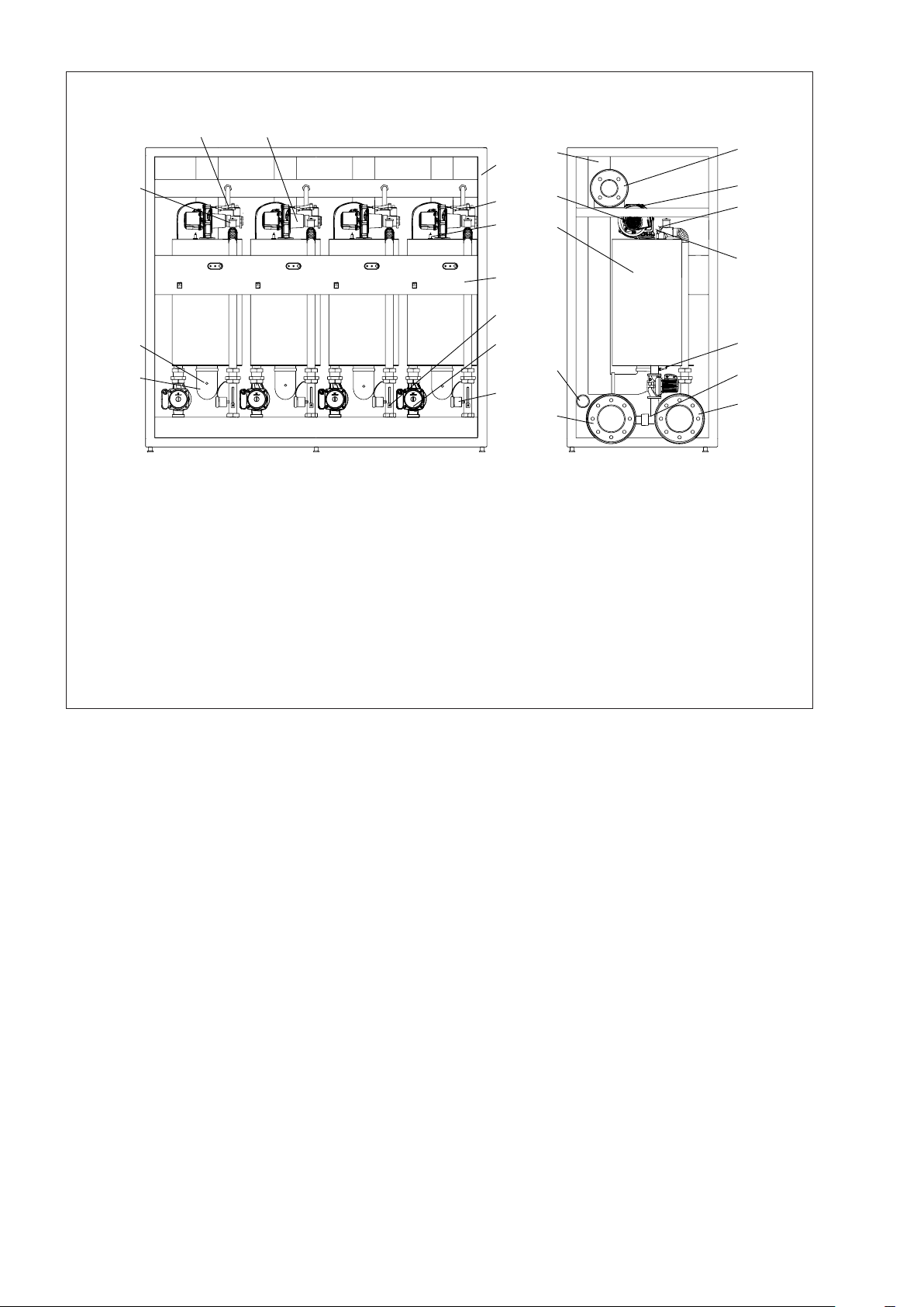
OUTLET
EXHAUST
15
7
6
12
5
8
11
FLUE DUCT
GAS
COMBUSTIBLE
6
16
4
1
Heat exchanger
2
Burner
3
Pump (or 2-way valve)
4
Smoke-exhaust flue non-return valve
5
Jet
6
Venturi tubes
7
Gas valve
8
Gas cock
9
Water return cock
14
2
18 18 18 18
1
3
9
3 3 3
DIMENSIONS AND CONNECTION POSITIONS
10
Water return manifold
11
Gas manifold
12
Gas pipe
13
Condensate drain manifold
14
Condensate drainpipe
15
Flue Manifold
16
Exhaust flue duct
17
Water flow manifold
18
Diff. Pressure switch
17
10
13
SYSTEM
INLET
SYSTEM
OUTLET
CONDENSATE
Figure 2
Figure 3
16 17
SYSTEM COMPONENTS
14
10
24
1
Frame
2
Control panel
3
Exchanger
4
Air inlet pipe
5
Fan
6
Return detection tap
7
Pump (or 2-way valve)
8
Unit Switch
9
Return probe
10
Exhaust flue probe
11
Water differential pressure switch
12
Gas valve
19
1
12
13
4
3
2
8
7
22
11
23
13
Ignition electrode
14
Automatic vent valve
15
Safety thermostat
16
Gas cock
17
Venturi tubes
18
Flow probe
19
Exhaust flue duct
20
Gas manifold
21
Water flow manifold
22
Condensate manifold
23
Water return manifold
24
Smoke-exhaust flue non-return valve
20
5
15
18
9
6
21
Figure 4
7

4 INSTALLATION
b
Power Plus Box P INT-EXT
stalled in conformity to the latest provisions of the
law and standards in force concerning heating units,
condensing boilers and/or other applicable regulatory provisions.
heating units must be in-
4.1 Product packaging and
identication
The
Power Plus Box P INT-EXT
packed and protected by a strapped carton.
heating unit is supplied,
- Efficiency according to 92/42/EEC Directive (η)
- Max pressure and temperature (Pms)
- Primary system (T)
- NOx class (NOx)
Figure 6
8
1
Boiler
2
Control panel
3
EC marking/Symbol cartouche
4
Packaging
5
Polyester corners
6
Polyester protection panel
7
Strap
Details of the product are written on the outside: model,
power, version and type of fuel. Contact your local dealer in
case of any differences with the order.
Ensure the goods are intact and complete after unpacking
them.
b
Do not leave the packaging within the reach of children as it could be a potential source of danger.
The tag on the front side of the boiler’s electrical board,
contains the following information:
- Product name
- Serial number
- Product identification code
- CE certification number
- Gas type and pressures from mains
- Power type from mains
- Rated heat capacity (Qn)
- Rated working power (Pn)
Figure 5
a
It is forbidden to remove or mishandle the identification plates, markings and any other making it difficult
to safely identify the product.
4.2 Installation premises
The heating unit must be installed in premises used exclusively for the latter conforming to standards and legislation
in force and where combustion exhaust products and combustion air intake is conveyed out of said premises. Where
combustion air is instead taken from the installation premises then the latter must be equipped with suitably sized
vents conforming to standards.
b
The space required to reach the safety and adjustment devices and to carry out maintenance must be
considered. We recommend leaving a space of at
least 500 mm at the back of the appliance.
b
Ensure that the degree of the heating unit’s electrical
protection is compatible with the characteristics of
the installation premises.
b
Electrical parts must be placed at a height of no less
than 500 mm from the ground where heating units are
supplied with fuel gas with specific weight exceeding
that of air.
b
Heating units may not be installed out in the open
(unless they are not specific outdoor units).
b
The heating unit is equipped with a frost protection
function, useful for installations where the temperature of the environment could be below 0°C. Gas and
electricity must be supplied for this system to work,
apart from a correctly pressurized water circulation
system and the system must not be in shutdown due
to any type of error.

4.3 Water connections
Power Plus Box P INT-EXT
2, 3 or 4 thermal elements which are common to all the boilers belonging to the same family and they have a thermal
power of 115 kW (Hi).
The modules can be installed in cascade according to the
power required by the installation and they can reach a
maximum of 32 thermal elements. The grouping of more
than one module allows to make some noiseless thermal
plants, with low thermal inertia and high power in a very
simple and rational way. Each thermal module is equipped
with the following connections which have been pre-set for
the connection to the system (see table).
MANIFOLD DIMENSION REMARKS
upper water
manifold
lower water
manifold
gas manifold 3”
condensate
manifold
flue pipe
(singol unit)
thermal modules are made up of
5” system inlet
5”
50 mm
110 mm See par 4.8
system
outlet
the gas
inlet can be
connected
simultaneously to the
two ends of
the boiler
connect
to sewer
system
See par. 4.6
CONNEC-
TION TYPE
Flanged
manifolds for
an easy con-
nection to
the system
Socked ends
manifolds
for an easy
realization
of the flue
system using
plastic pipes
(PP).
4.4 System cleaning and water
treatment
This preventive measure is absolutely required whenever a
heat generator needs to be replaced in but it is in any case
recommended also on new systems, in order to remove
any waste, dirt, working residues, etc.
To clean the system, if the old generator is still present in
the system:
- add a descaling additive to the system water (contact
the B Technical Assistance Centre);
- Have the system operate with the generator ON for
approximately 7 days;
- Discharge the system’s dirty water and wash the system once or several times using clean water.
If the system is very dirty, repeat the last procedure one
more time.
If the old generator is not present or available, use a pump
to circulate the water + additive through the system for
about 10 days and perform a final washing as described in
the previous paragraph.
At the end of cleaning operations, before installing boiler
Power Plus Box P INT-EXT
to the system water (contact the B Technical Assistance Centre);
a
Please contact the B Technical Assistance Centre
for flushing out the water circuit inside the exchanger.
Do not use incompatible liquid detergents, including
acids (e.g. hydrochloric acid and similar acids) at any
whatsoever concentration.
, it is advisable to add protection)
4.5 Positioning and preparation for
installation
Follow the procedure below to install the thermal groups:
1 After unpacking the boiler/s, establish the output direc-
tion of the water, gas and condensate pipes (e.g.: left
or right connection). Also establish the modality and the
position of both the flue manifold and the eventual air
manifold (in case of installation with outside air intake).
It is recommended to take into account the electric connections (230 V supply) of the thermal group too (see
paragraph 6.2).
Please note that each pipes connection to the system can
be indifferently made at the right of left side of the thermal
group.
However, it is suggested to follow one of the schemes of
installation reported on this manual (see chapter 5).
2
Place the thermal group/s near the inlet and outlet pipes
of the system.
right or left outlet of water, air, smokes, condensate, gas
pipes (e.g.: air inlet on the right, water outlet on the left,
gas on the right).
The position of each
the area of installation can vary according to specific
requirements of space or to the type of the installation
itself (e.g.: leaned against the wall, back-to-back, etc.);
in any case, make sure that same necessary space
is left for the passage of the electric supply cables of
each
Power Plus Box P INT-EXT
open. Space is also required in case of maintenance
services of the flue, condensate, and gas pipes.
3 1. Mount the side panels of the
EXT
and connect the first (or the only) thermal group of
the battery to the system, use the correct connections
and carefully avoid any sudden variation of section
among the piping of both the boilers and the system.
If necessary, adjust the boiler’s feet height to level the
frame of the boiler and to open the doors easily.
4 2. Once water connections between the first group
and the system have been made, connect successively
the other eventual thermal groups to the first one, following the advice above. Use sections male/male Ø 50
mm of about 13 cm lengths to connect the different condensate discharges.
The groups can be installed either with
Power Plus Box P INT-EXT
and to let the front panel
Power Plus Box P INT-
inside
9

10
4.6 Condensate outlet
The condensate water produced by
EXT
a normal running conditions is evacuated into a spe-
cial manifold.
Drainage must be done at atmospheric pressure, i.e. by
dripping into a connected drain-trap, as follows:
- install a drip at the condensate drainage manifold;
- connect the drip to the sewerage mains by a draintrap;
- be ready to use a neutralizer where required (see project cig E.01.08.929.0; ATV A 115).
There is generally no need to take any special precautions
for draining condensate.
We advise using plastic (PP) piping for building the condensate drainage.
a
DO NOT for any reason use pipes in copper or in any
other material not specifically used for this particular
scope, as the condensing action could cause rapid
degradation.
i ≥ 3°
i
(*)
Power Plus Box P INT-
4.7 Water circuit
WORKING PRESSURE
The maximum working pressure of the boiler is 6 bar (600
kPa) whilst the minimum is 0.5 bar (50 kPa).
b
It is compulsory to install devices along the topping
up/supply line as well as the water circulation system
to protect the installation from pressures exceeding
550 kPa, in conformity to prescriptions given in the
EN 60335-2-102.
b
Do not expose the exchanger to cyclic changes in
pressure as fatigue stress does a lot of harm to the
system components. Should the water system suddenly start generating changes in pressure it is compulsory to use the protection devices to make the
boiler work at a regular pressure.
b
Installation pressure control must be done under cold
conditions.
FILLING UP THE BOILER
The boiler must be filled up by connecting the water from to
the mains to any part of the installation.
b
It is compulsory to use a standard filling device
(EN61770 type) for coupling up to the mains specifically preventing the back-flow of liquid from installation to water mains.
EMPTYING THE BOILER
Emptying of the system is made by acting on the discharge
valves of each unit and in some points of the hydraulic system specific for this purpose.
For more information on the characteristics of hydraulic
system see Chapter 5 in which different types of plant are
shown.
(*)
minimum
distance
300 mm
minimum
distance
10 mm
Condensate collector
(at atmospheric pressure)
(*) Fill the siphons with water.
Furthermore, should the vertical part of the flue exhaust
duct have to be prolonged by more than 4 metres the condensate drain-trap will have to be placed at the foot of the
piping. The working height of the drain-trap must be at
least 30 cm. The drain-trap outlet must then be connected
up to the sewerage mains.
b
The condensate drain must be connected to the sewerage mains in such way as to prevent it from being
frozen under any circumstances.
b
Always install a condensate drain in the exhaust flue
duct at no more than 1 m from the boiler
i > 3%
Civil drain
Fig. 7
4.8 Exhaust ue
The chimney should be as straight as possible, sealed and
isolated. Should not have occlusions or narrowing.
b
The overall potential of thermal groups
Box P INT-EXT
be installed only in rooms that have venting opening
to the outside according to actual law (italian D.M.
12.04.1996).
b
The
Power Plus Box P INT-EXT
be connected to a exhaust pipe system in flame retardant polypropylene (PP) or suitable materials according to UNI EN 677 and associated standards.
a
DO NOT for any reason use piping not specifically
designed for this specific scope as the condensing
action could cause rapid degradation.
b
Where collectors are used to evacuate the smoke, the
presence of non-return valves within each unit stops
the products of combustion of the active units entering the boiler room by means of the closed unit intake
ducts.
a
In the event of installation with air intake from the
premises (both in the heating unit and externally)
avoid obstructing the passage of air under the metal
cupboard.
Series is more than 35 kW, so they can
series generators must
Power Plus
If you decide to bring together in one manifold the discharges of each unit, the diameter of the pipe to be used
for one or two units
nected in series is Ø200 mm (see Figure 8). For cascade
installations where there are more than two machines the
diameter of the exhaust manifold must be properly sizing,
or simply connect up to two
multiple lines Ø200 separated.
Installed power
(kW)
230 60 345 60 460 40 60
575 25 60
690 - 60
805 - 55
920 - 40
1035 - 35
1150 - 25
Power Plus Box P INT-EXT
Power Plus Box P INT-EXT
Maximum Pipe Length (m)
with Ø 160 with Ø 200
series con-
using
Figure 8
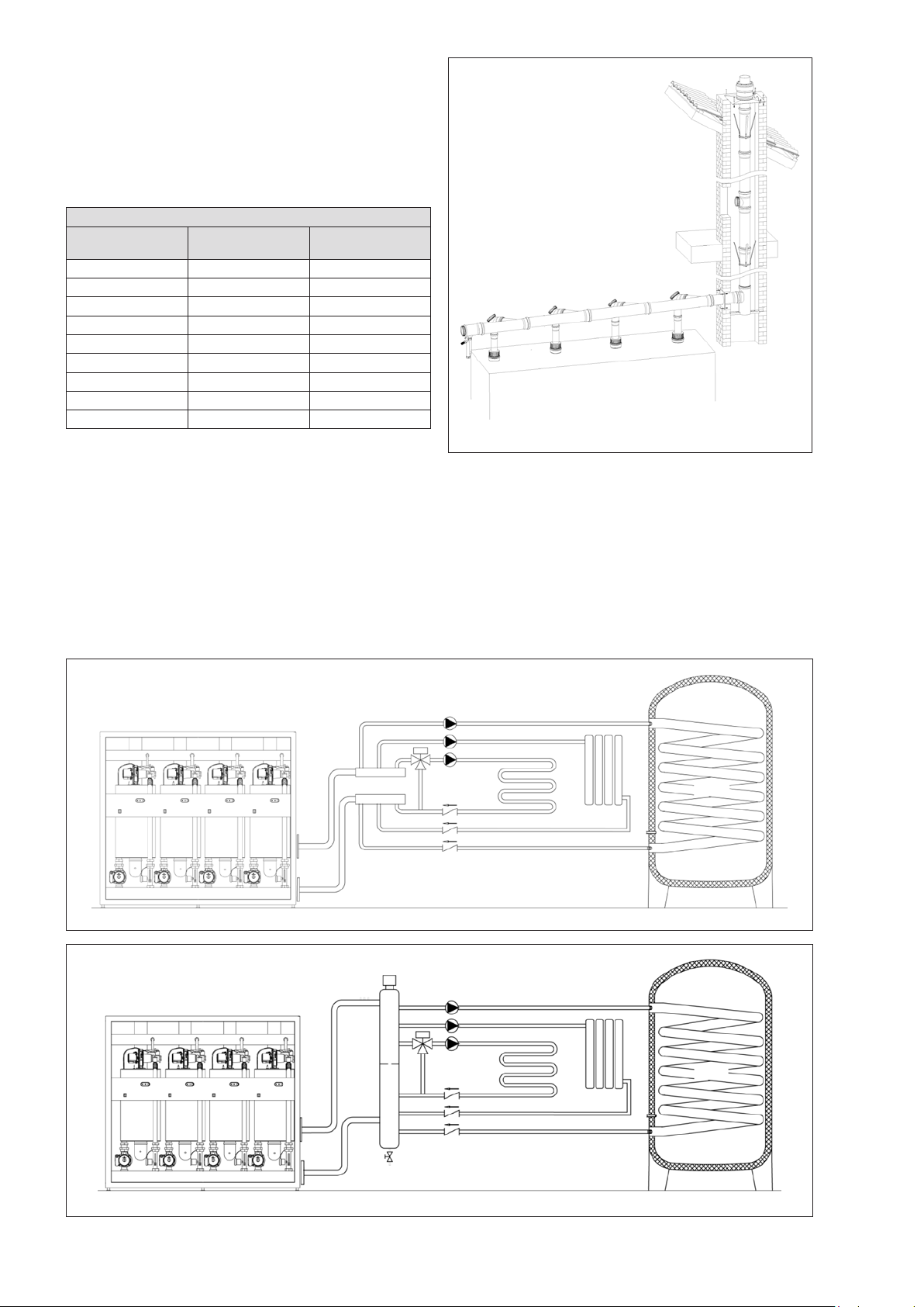
5 INSTALLATION DIAGRAMS
An installation diagram must generally be adapted to the
manufacturing characteristics of the relevant heating unit,
with the purpose of exploiting the boiler potentials to the
full and maintain the entire installation efficient for as long
as possible.
The Figure 9 is shown an installation without a mixing element, in Figure 10 is shown a installation with a mixing
element.
11
Figure 9
Figure 10

12
6 ELECTRICAL SYSTEM
6.1 Power supply
A detailed wiring diagram of the heating unit is shown in
caption 11, at the diagram and technical data section.
Installation of the heating unit requires connection to a 230V
- 50Hz grid system and must be done with good workmanship in conformity to the electrical regulatory provisions in
force.
It is best to install a differential circuit-breaker switch along
the line supplying power to the boiler.
b
Adapters, multiple sockets, extensions to feed the
appliance are not allowed.
The thermal generator must always be connected to the
"master board" which contains the board that governs the
system and manages probes of the circuit, pumps and accessories.
The Figure 17 is shown the terminal of the master board,
with the connections to different external devices.
b
Always check the effectiveness of the electricity
earthing system, compulsory for the appliance and
used for connecting up to the heating unit. The electronics could in fact put the entire heating unit into
safety shutdown should the latter not be compatible.
b
Make sure that the water and heating pipes have not
been used as earths for the electrical installation.
They are absolutely unsuited for this usage.
Wiring at a voltage of 230 V must be separated from those
at a voltage of 24V, using raceways or separate PVC tubes.
Make sure that the electrical features (volt, absorption,
starting current, etc.) of the external electrical components
(thermoregulators, solenoid valves, weather probes, etc.)
are compatible with the inlets and outlets available before
connecting them up.
Relays and/or ancillary contactors are to be used to connect up the external electrical components, which must be
installed on a special electrical board externally.
This solution also enables circulators, valves, etc. to function in emergency mode, i.e. should the boiler master board
not be serviceable.
a
Do not touch the electrical apparatus with parts of the
body wet or damp or with bare feet.
a
Do not leave the appliance exposed to atmospheric
agents (rain, sun, wind, etc.) unless it is the special
model for out of doors.
Always refer to the data given in the diagrams in this handbook for operations of an electrical nature.
Remember that
ages caused by ignoring the information given in the wiring
diagrams of this manual.
a
Never turn off the boiler while it is functioning normally (with burner ignited) suddenly cutting off the
power supply with the on-off switch. This could cause
abnormal overheating in the primary exchanger. Use
a room thermostat or remote control to turn off (whilst
heating system is on).
B is not to be held liable for any dam-
6.2 Electrical connections
b
Qualified personnel only may work on the electrical
system and in compliance to provisions of the law,
with particular attention to rules on safety.
a
Lock the cables in their cable clamp designed to ensure the latter are always in the correct position inside
the appliance.
6.2.1 Connection to mains
When installing a single
the connection must be made in accordance with current regulations regarding electrical safety, using a multi
sheathed cable H05 VV-F-3GI with minimum section of the
conductors of 1,5 mm
ture, abrasions and incidental contact.
The power cord is to be connected to the switch, located
behind the boiler control panel. To access the switch, remove the protective sheet metal by removing the screws
connecting. The protective conductor (earth) terminal is to
be connected to the general earth strip next to the switch.
Fix the cable by its cable clamp and supplied anchorages
to ensure it is correctly in place inside the appliance and
to prevent it from coming into contact with parts at high
temperatures (burner, etc.).
b
The length of the grounding cord should be higher
than other conductors (phase, neutral). In case of
disconnection of the power cord the cables of the
conductors are strained before the grounding one.
b
The rubber cableguides placed on the structure of
the equipment have not to be removed because
their purpose is to protect the cables from wear that
occurs in direct contact between cable and frame
equipment. To pass a cable is sufficient to drill the
cableguides.
Power Plus Box P INT-EXT
2
, suitably protected against mois-
Series
a
It is forbidden to pull, detach, twist the wiring coming
out of the heating unit, even if unplugged from the
power supply.
a
Do not allow people without experience to use the
appliance and switch off the heating unit if the power cable should break; call in qualified personnel to
replace it.

6.2.2 Master board connection
Follow the instructions reported on the previous paragraph
in order to connect the Master Board independently to the
electricity network. The Master Board needs to be connected to the related equipment (or to the equipment battery)
by means of a special Bus connection with bi-polar cable
(cable not supplied).
Use a H05-VV-F-3GI sheathed cable to make the connection. The minimum section size of the cable conductors
needs to be of 0,5 mm2 (with adequate length). Connect
one side of the bi-polar cable to the mounting jig that is
placed on the Master board (see arrow, Figure 11) and
connect the other side of the cable inside the boards panel
that is placed inside the equipment.
The Figure 12 shows the left jig placed next to the equipment switch on button (The connection can me made also
to the right jig; see Figure 13). Use the same jigs shown on
Figure 12 and Figure 13 in case you need to connect more
than one equipment (see paragraph 6.4.2).
As largely detailed on the following paragraphs, inside the
Master board you will find the auxiliary devices jigs ( e.g.
pumps, probes, mixing-valve, etc…).
Remove the DIN guide (placed inside the Master Board) to
access the mounting jig.
Unscrew the two screws on the DIN guide as indicated on
Figure 14. Once unscrewed the two screws, remove the
Din bar to fully access the jig inside the Master Board (see
Figure 15.
Figure 13
Figure 11
Figure 12
13
Figure 14
Figure 15

6.2.3 Connection to thermoregulators
Power Plus Box P INT-EXT
an extremely versatile control and operating system, able
to operate three independent systems functioning at different temperatures. The procedure for connecting up the
output signal to the specific points on the terminal board
will be illustrated in the following pages (see Figure 17).
H05-VV-F type cables with minimum external diameter of
5mm and adequate conductor section may be used for
thermoregulation and low voltage systems, being careful to
fix the latter to their cable guides.
heating units are equipped with
6.2.4 Connection to pumps
Power Plus Box P INT-EXT
simultaneous management of up to three circulators.
b
Therefore, if a low temperature circuit supplied by its
own circulator is present and a general pump is to be
installed on the system, it will be necessary to choose
which one of the two devices should be managed by
the system's electronics.
This operation is done by a Technical Assistance Centre
authorized by B during commissioning the system, by
setting an appropriate parameter (specifically n. 34 in the
list of parameters).
b
The pumps and others external components have to
be installed using an adequate relay/commutator, as
shown in Figure 16.
Use a H05-VV-F type cable with minimum external diameter of 6 mm and adequate conductor section to connect the
terminal board to the relay (to be housed in a special external board), being careful to fix the latter to its cable guide.
regulation system includes the
For example, by connecting the low temperature circulator to a timer and/or external room thermostat the electrical
installation will be the one shown in Figure 18. By this system is possible to power on circulators (external devices)
directly from the network with no electrical load passing
through the fuse of the board.
Moreover, in case of emergency mode, the manual device
0, 1, AUTO controls the operation of the pump regardless
of what the board. For these reasons it must explicitly provide for the use.
Use a bi-polar cable of the power cable sort (unless otherwise recommended by the component’s manufacturer.
6.2.5 Connection to room thermostats (on/
off)
Connect up the high temperature system room thermostat
to terminals 9. and 10 (Figure 17).
The thermostat for the low temperature system must instead be connected to terminals n. 11 and 12 (Figure 17).
6.2.6 Connection to weather temperature
probe
If you want to use a weather thermoregulator, the external
probe (optional) must be connected up to terminals n.7
and 8 (Figure 17). The external probe must be placed on
an outer wall facing north to north-east at a height of at
least 2.5 metres and at a distance from windows, doors
and air vents.
Protect the probe from direct exposure to the sun. Contact
the Technical Assistance Centre authorized by B if the
curve has to be adjusted or the weather function excluded.
14
Figure 16
 Loading...