

Page 1
Installation Manual
CONDENSING
Power Plus Box 1001 INT-EXT
Installation Manual
EN
Page 2
This manual, Code 20073959 - Rev. 4 (12/15) comprises 40 pages.
2
RANGE
MODEL CODE
Power Plus Box 1001 INT 20067835
Power Plus Box 1001 EXT 20067836
CERTIFIED COMPANY
UNI EN ISO 9001:2008
UNI EN ISO 14001:2004
This manual, Code
- Rev.
comprises
pages.
ENGLISH
Contents
CONTENTS
The following symbols are used in this manual:
b
CAUTION! =
Identifies actions that require caution
and adequate preparation.
a
STOP! =
Identifies actions that you MUST NOT do.
1 GENERAL INFORMATION ................3
2 WARNINGS............................3
3 TECHNICAL FEATURES .................4
3.1 Main features ............................ 4
3.2 Advantages.............................. 5
3.3 Safety devices............................ 5
3.4 Components ............................. 6
4 INSTALLATION.........................9
4.1 Product packaging and identification.......... 9
4.2 Installation premises ....................... 9
4.3 System cleaning and water treatment ........ 10
4.4 General instructions ...................... 10
4.5 New heating systems ..................... 10
4.6 Upgrading existing systems ................ 10
4.7 Corrosion............................... 10
4.8 Positioning and preparation for installation..... 11
4.9 Condensate outlet........................ 11
4.10 Water circuit ............................ 12
4.11 Exhaust flue............................. 12
5 INSTALLATION DIAGRAMS .............12
6 ELECTRICAL SYSTEM .................14
6.1 Power supply ........................... 14
6.2 Electrical connections..................... 14
6.2.1 Connection to mains ...................... 14
6.2.2 Connection to thermoregulators .............15
6.2.3 Connection to pumps ..................... 15
6.2.4 Connection to room thermostats (on/off) ...... 15
6.2.5 Connection to weather temperature probe..... 15
6.2.6 Frost protection .......................... 16
6.2.7 Connection to 0-10v external thermoregulator ..17
6.2.8 Connection to alarm device ................ 17
6.3 Emergency mode ........................ 17
7 GAS VALVE CALIBRATION ..............18
8 USE AND ADJUSTMENT ................19
8.1 Control panel: description.................. 19
8.2 Display mode ........................... 20
8.3 Display mode ........................... 20
8.4 Changing the user parameters .............. 21
8.5 Monitor mode ........................... 21
8.6 Installer programming mode................ 22
8.7 Test mode .............................. 23
8.8 Error mode ............................. 23
8.9 Permanent block ......................... 23
9 SETTING FUNCTIONING PARAMETERS ...24
9.1 Setting the heating parameters.............. 24
9.2 Setting the DHW parameters ............... 25
9.3 Heat control setting....................... 26
10 LIST OF PARAMETERS .................31
11 ERROR LIST ..........................33
11.1 Master board errors ...................... 33
11.2 Slave board errors ....................... 33
12 WIRING DIAGRAMS....................35
13 TECHNICAL SPECIFICATIONS ...........37
Page 3

3
1 GENERAL INFORMATION
Dear Customer,
congratulations on your choice and thank you for placing
your confidence in our products. With
Power Plus Box 1001
you have chosen technology that is the very essence of
energy saving and functionality.
Moreover, all B products conform to the strictest
directives and European standards in force.
This product was produced, amongst others, in conformity
to the following directives and standards:
- Directive 2009/142/EC - Gas Appliances
- Directive 92/42/EEC on efficiency requirements
and Annex E and Pres. Republic Decree n. 412, 26
August 1993 (****)
- Electromagnetic Compatibility Directive 2004/108/EC
- Low Voltage Directive 2006/95/EC
- Ecodesign Directive 2009/125/CE for energy-related
products
- Delegated Regulation (EU) N. 813/2013
- EN 15417 Gas-fired central heating boilers - Specific
requirements for condensing boilers with a nominal
heat input greater than 70 kW but not exceeding
1000 kW
- EN 13836 Gas fired central heating boilers - Type B
boilers of nominal heat input exceeding 300 kW, but
not exceeding 1000 kW.
The
Power Plus Box 1001
condensing modular systems
moreover conform to the regulatory provisions pursuant to
the INAIL “R” File, section R.3.B.
B has been certified with UNI EN ISO 9001/2000 since
22.07.2004.
Power Plus Box 1001
is furthermore a product having to its
credit:
- European Conformity Mark (based on Directive
92/42/CEE) issued by the authorized German
certification organization ;
- Maximum energy efficiency class (according to
Directive 92/42/EEC) identified by the symbol ****;
- Classified in the strictest class for nitrogen oxiderelated pollution (fifth grade according to UNI EN
297)
- Patented heat exchanger.
2 WARNINGS
b
The heating unit must be used for the purpose for
which it was specifically designed and produced. Any
whatsoever contractual or extra-contractual liabilities
for damages caused to persons, animals or objects
due to errors in installation, adjustment, maintenance
and improper usage are to be excluded.
b
Installation must fully comply with provisions of
the law in force and instructions provided by the
manufacturer to ensure safety and correct functioning,
always calling upon professionally qualified technical
personnel who will issue the declaration of conformity
for the installation accomplished with good
workmanship, in compliance to regulatory provisions
in force and guidelines given in this handbook. The
appliance must be installed in appropriate premises
and together with the specific systems installed
according to the law.
b
Commissioning will be carried out by personnel from
the authorized Technical Assistance Centre only and
within 8 days from when the appliance was installed.
After initial ignition the Technical Assistance Centre
will fill in the warranty certificate, leaving the user their
part to be kept, marking the beginning of the period
of guarantee at the terms and conditions specified
on the relative slip.
The appliance in its original packing
may be exposed to temperatures between 4°C and 40°C.
Do not expose the appliance to bad weather conditions
after it has been unpacked, anyhow to temperatures
below 4°C or above 40°C until it has been connected
up to the water, gas and electricity mains so as to be
able to activate the frost protection systems described in
paragraph 6.2.6.
b
Check that the product is complete, undamaged
and as ordered as soon as you receive it. Report any
discrepancies or damage to the B dealer who sold it.
b
In case of leaks, disconnect the heating unit from the
mains, close the water from the mains and promptly
contact the Technical Assistance Centre.
b
Regularly check that the condensate drain is free from
obstruction.
b
Regularly check that the working pressure of the water
circulation system, when cold, is below the maximum limit
specified for the appliance. If not, contact the Technical
Assistance Centre.
b
Maintenance jobs on the heating unit must be carried out
by personnel from the authorized Technical Assistance
Centre. Maintenance must be performed at least once a
year. Correct maintenance is essential for safety as well
as for the efficiency and long working life of the product.
Proper maintenance keeps consumption and emissions
down, and ensures that the product continues to operate
reliably over time. Analyse the combustion fumes before
commencing maintenance. The results of fume analysis
can give a clear idea of what servicing or repairs are
needed.
b
We recommend cleaning inside the exchanger once
a year, extracting jet and burner and removing any
installation debris by suction. This operation will be done
by personnel from the Technical Assistance Centre only.
b
The warranty slip endorsed during the course of
commissioning will have to be produced for any servicing
required during the guarantee period. The manufacturer
shall not be held liable for any damages caused by
mishandling, improper use or errors in installation, use
and maintenance work on the appliance. In the event
of breakdown or malfunction switch off the appliance,
avoiding to make any attempt to repair it and contact the
Technical Assistance Centre.
b
This manual must be read carefully for the boiler to be
used rationally and safely, and must be kept with care
so as to be on hand where required by the technician or
installer, to facilitate the appropriate installation, running
and maintenance of the boiler. B will not be held
liable for any translations possibly giving rise to wrong
interpretation. This manual is an integral part of the
heating unit and must consequently be kept with care
and must ALWAYS accompany the boiler even when
passed on to another owner or user or transferred to
another installation. Ask the Technical Assistance Centre
for another copy if it should be lost or damaged.
Page 4

4
a
Children and people with disabilities or without
experience and specific knowledge are forbidden to use
the heating unit unless they are assisted by a qualified
person responsible for their safety.
It is forbidden to use
electrical devices or equipment, such as switches,
appliances, etc. if there is a smell of gas or un-burnt
products. If so:
- ventilate the room, opening doors and windows;
- close the gas valve at the mains;
- immediately call in the Technical Assistance Centre
or professionally qualified personnel.
a
It is forbidden to touch the heating unit with bare feet
or parts of the body wet.
a
It is forbidden to start on any technical or cleaning
jobs before disconnecting the heating unit from the
power mains.
a
It is forbidden to alter the safety and adjustment
devices without permission and instructions from the
heating unit manufacturer.
a
It is forbidden to obstruct the condensate drain.
a
It is forbidden to pull, detach, twist the wiring coming
out of the heating unit, even if unplugged from the
power supply.
a
It is forbidden to obstruct or reduce the size of air
vents.
a
It is forbidden to expose the boiler to atmospheric
agents (if it is not a specific unit for outdoors).
a
It is forbidden to leave containers or flammable
substances in the premises where the boiler is
installed.
a
Do not dispose of packaging material into the
environment, or leave it within the reach of children,
since it can become a potential hazard. Dispose of
packaging material in compliance with applicable
legislation.
a
The user is forbidden to open the cupboard containing
the heating unit. Any jobs on the inside of the latter
must be done by the Technical Assistance Centre or
by qualified personnel.
a
It is forbidden to discard the product as household
waste. At the end of its service life, it can be
consigned to specific selected waste centres
provided by the local authorities or else to dealers
providing this service. Disposing of a domestic
appliance separately will prevent possible harmful
consequences for environment and health derived
from inappropriate disposal, likewise making it
possible to recuperate the materials it is made of with
substantial savings in energy and resources.
3 TECHNICAL FEATURES
3.1 Main features
Power Plus Box 1001
is a modular condensing, premixed,
jet heating unit, comprising a modular unit at 26 to 128 kW
equipped with weather adjustment device.
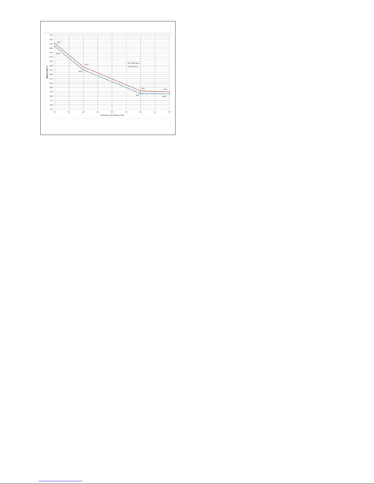
The efficiency of the generators reaches 109% based
on the lower heat potential of natural gas (Hi) making it
possible to use a flue manifold entirely made of plastic
(PP). The system also enables continual modulation of the
gas and combustion air flow.
The
Power Plus Box 1001
heating unit is the optimum as far
as operating costs (up to 109% efficiency per Hi, see Figure
1), reliability and flexibility is concerned. Rapid connection
to any type of heating and domestic hot water system
with accumulation is in fact possible owing to a special
more powerful heat exchanger, new electronic control,
modulating electronic circulator and high efficiency.
Furthermore, the “master” board, supplied with each
heating unit, ensures the latter a simple conFiguretion and
enables it to be adapted to any type of system, optimizing
its performance in terms of creating comfort and cutting
down on consumption.
All the safety devices provided in the INAIL “R” File for
this particular application, have been installed on the flow
manifold, downstream from the last combustion unit.
A special water compensator is housed inside the hood
with attachments for simple connection to the systems
directly controlled by the master board which is supplied
with the heating unit:
- Direct system (high temperature)
- Mixed system (low temperature)
- Hot water system.
Distribution units are available as an accessory for each of
the above mentioned systems.
The heating unit thus becomes a complete, versatile
functional “system” to install in a variety of plant typologies.
All the systems and relevant functional components
(circulators, mixer valve and temperature probe) are
entirely controlled by the master board and are connected
up to the latter, without the help of additional boards.
Room thermostats in the unit’s system-related areas can
also be connected up to said board.
The system can also be extended to numerous additional
zones by a board called “zone master”, which is not
included in this manual.
Page 5
5
Figure 1
3.2 Advantages
- Totally pre-mixed micro-flame jet burner;
- condensing stainless steel exchanger, with efficiency
up to 109% (see Figure 1);
- maximum exhaust flue exit temperature 80°C;
- PPS plastic exhaust flue manifold, self-extinguishing
(see paragraph 4.11);
- modulating electronic primary circulator at low
consumption;
- weather temperature adjustment device supplied;
- hot water and systems control at different
temperatures, with or without function priority;
- automatic summer/winter switch-over;
- minimum flow capacity of thermal carrier fluid
controlled by a differen-tial pressure switch;
- compensator with inner partition for connection to
three systems;
- INAIL safety organs mounted in factory;
- appliance complete and ready to be connected up to
the installation.
3.3 Safety devices
All the heating unit functions are electrically controlled and
any fault will cause arrest of the heating unit and the gas
valve to automatically close.
The water circulation system includes:
- automatic resetting safety thermostat;
- differential water pressure switch acting as a
flowmeter;
- temperature probe on flow and return controlled
by a certified electronic device to carry out safety
functions with dual-processor technology. The
flow temperature is continually controlled by these
devices as well as the Δt between flow and return by
acting on the primary circulator modulation;
- modular flow temperature adjustment.
The combustion system includes:
- gas solenoid valve in B+C class with pneumatically
compensated gas flow dependent on air intake flow
capacity (air/gas ratio 1:1);
- ionization electrode for continual flame control;
- exhaust flue duct temperature control.
Protective actions and therefore closure of gas valves on
each heating unit are activated in the following cases:
- flame burnt out;
- over-temperature in exchanger system;
- high temperature of exhaust fumes;
- reduced air flow.
a
The appliance must not be started up, even
temporarily, where the safety devices have been
mishandled or excluded.
b
Safety devices must be replaced by the authorized
Technical Assistance Centre only, exclusively using
original parts.
Page 6

6
3.4 Components
Power Plus Box 1001
comprises a metal cupboard
containing the condensing combustion unit connected to
a separator, also acting as a distribution organ to three
distinct systems (high T, low T and hot water), see diagram
in Figure 2.
Figure 2
1
Heat exchanger
2
Burner
3
Jet
4
Venturi tubes
5
Gas valve
6
Vent valve
7
Safety thermostat
8
Min. and differential pressure
9
Flow temperature control
10
Return temperature control
11
Flue temperature control
12
Return pipe
13
Flow pipe
14
Gas pipe
15
Air inlet
16
Exhaust flue duct
17
Condensate outlet
18
Condensate manifold
19
Two-way gas valve
20
Fuel check valve
21
Separator
22
Separator drain cock
23
Separator vent valve
24
Modulating circulator
25
VIC probe pit
26
Safety valve
27
Max. INAIL pressure gauge
28
INAIL gauge
29
INAIL thermometer
30
Expansion tank opening
Page 7

7
DIMENSIONS AND CONNECTION POSITIONS
Power Plus Box 1001 INT
Figure 3
Power Plus Box 1001 EXT
Figure 4
1
Flow low temperature
2
Return low temperature
3
Flow high temperature
4
Return high temperature
5
Return high temperature
6
Return hot water
7
Flow low temperature*
8
Return low temperature*
9
Return high temperature*
10
Return hot water*
11
Condensate outlet
12
Exhaust flue duct
13
Gas inlet
Page 8

8
SYSTEM COMPONENTS
Figure 5
1
Hydraulic separator
2
Flow pipe
3
Return pipe
4
Gas pipe
5
Vent valve
6
Cock
7
Drain cock
8
Temperature gauge
9
Gauge fitting with cock
10
Damper device for gauge
11
Pressure gauge
12
Thermometer pit
13
Maximum pressure switch
14
Fuel check valve
15
5.4 bar safety valve
16
Expansion tank/filling fitting
17
Flow probe pit
18
Exchanger
19
Burner
20
Fan
21
Venturi tubes
22
Air inlet pipe
23
Gas valve
24
Exhaust flue duct
25
Condensate drainpipe
26
Vent valve
27
Ignition detection electrode
28
Safety thermostat
29
Gas cock
30
Diff. Pressure switch
31
Condensate drain manifold
32
Return probe
33
Exhaust flue probe
34
Master board
35
Slave board
36
Pump control board
37
Flow hot water system connection
38
Return hot water system connection
39
Flow high temperature connection
40
Return high temperature connection
41
Flow low temperature connection
42
Return low temperature connection
43
Modulating circulator
Page 9
9
4 INSTALLATION
b
Power Plus Box 1001
heating units must be installed
in conformity to the latest provisions of the law
and standards in force concerning heating units,
condensing boilers and/or other applicable regulatory
provisions.
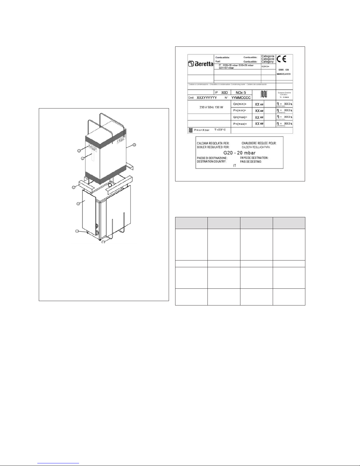
4.1 Product packaging and
identication
The
Power Plus Box 1001
heating unit is supplied, packed
and protected by a strapped carton.
Figure 6
1
Boiler
2
Control panel
3
EC marking/Symbol cartouche
4
Packaging
5
Polyester corners
6
Polyester protection panel
7
Strap
Details of the product are written on the outside: model,
power, version and type of fuel. Contact your local dealer
in case of any differences with the order.
Ensure the goods are intact and complete after unpacking
them.
b
Do not leave the packaging within the reach of
children as it could be a potential source of danger.
The tag on the front side of the boiler’s electrical board,
contains the following information:
- Product name
- Serial number
- Product identification code
- CE certification number
- Gas type and pressures from mains
- Power type from mains
- Rated heat capacity (Qn)
- Rated working power (Pn)
- Efficiency according to 92/42/EEC Directive (η)
- Max pressure and temperature (Pms)
- Primary system (T)
- NOx class (NOx)
Figure 7
a
It is forbidden to remove or mishandle the identification
plates, markings and any other making it difficult to
safely identify the product.
CONNECTION
DIMENSION
CONNECTION
TYPE
REMARKS
Water
distribution
2” Threaded
Flow/return
connections
for hot water,
high/low
temperature
systems
Gas fitting 1” Threaded
Exhaust flue
duct
Ø110 Socked
Piping in
plastic
material
allowed
Condensate
outlet
50 mm Socked
See
paragraph
4.1.8
4.2 Installation premises
The heating unit must be installed in premises used
exclusively for the latter conforming to standards and
legislation in force and where combustion exhaust
products and combustion air intake is conveyed out of said
premises. Where combustion air is instead taken from the
installation premises then the latter must be equipped with
suitably sized vents conforming to standards.
Page 10

10
b
The space required to reach the safety and
adjustment devices and to carry out maintenance
must be considered. We recommend leaving a space
of at least 500 mm at the back of the appliance.
b
Ensure that the degree of the heating unit’s electrical
protection is compatible with the characteristics of
the installation premises.
b
Electrical parts must be placed at a height of no less
than 500 mm from the ground where heating units are
supplied with fuel gas with specific weight exceeding
that of air.
b
Heating units may not be installed out in the open
(unless they are not specific outdoor units).
b
The heating unit is equipped with a frost protection
function, useful for installations where the temperature
of the environment could be below 0°C. Gas and
electricity must be supplied for this system to work,
apart from a correctly pressurized water circulation
system and the system must not be in shutdown due
to any type of error.
4.3 System cleaning and water
treatment
It is ABSOLUTELY NECESSARY to treat the water system
for the heating unit to work properly and to guarantee its
service life together with all its components.
This not only applies to jobs carried out on existing
installations but also on new installations.
Sludge, lime-scale and pollutants present in the water can
cause permanent damage to the heating unit, also within
a short time and regardless of the quality standards of the
materials used.
Contact the Technical Assistance Centre for any further
information on type and use of additives.
Chemical-physical characteristics of the water must
conform to the European CSN EN 14868 standard and to
the table given here below:
Initial
filling
water
Regular
service
water (*)
ph 6-8 7,5-9,5
Hardness < 10° < 10° °fH
Electrical
conductivity
< 150
μs/cm
Chlorides < 20 mg/l
Sulphides < 20 mg/l
Nitrides < 20 mg/l
Iron < 0,5 mg/l
(*)
Value of water in circulation system after functioning for
8 weeks.
b
Where softened water is used it is compulsory
to re-check conformity to tolerances for water in
regular service after 8 weeks from topping up and in
particular the electrical conductivity.
b
No controls are required when using de-mineralized
water.
4.4 General instructions
b
An automatic filling system may not be used for
topping up, which must be done manually and
recorded in the unit handbook.
b
If there are more than one boiler, they must all be
put into service either contemporarily or with a very
low rotation time during the initial period of service,
so as to evenly distribute the limited quantity of initial
lime-scale.
b
A flushing cycle must be programmed after the plant
has been installed to flush out any installation debris.
b
Water used for filling or for eventually topping up the
system must always be filtered (synthetic or metal
mesh filters with filtering capacity of no less than
50 micron) to avoid deposits possibly triggering off
under-deposit corrosion.
b
The heating system must be flushed out and cleaned
with good workmanship before filling up the existing
systems. The boiler may not be filled until after the
heating system has been flushed out.
4.5 New heating systems
b
The system must be filled up slowly the first time;
once it is filled and the air expelled it should never
need to be topped up again.
b
The system must be turned to maximum service
temperature during the initial ignition to facilitate
deaeration (a too low temperature prevents the gas
from coming out).
4.6 Upgrading existing systems
Where the boiler has to be replaced it is not recommended
to fill up again if the quality of the water in the existing
systems conforms to specifications. If the quality of water
fails to conform to specifications, we recommend either
re-treating it or separating the systems (the water quality
requirements must be respected in the boiler system).
4.7 Corrosion
Under-deposit corrosion
Under-deposit corrosion is an electrochemical process,
due to the presence of sand, rust, etc., inside the mass
of water. These solid substances generally deposit on the
bottom of the boiler (sludge), on tube and pipe heads or in
the gaps between pipes and tubes.
Micro-corrosion phenomena may be triggered off owing
to the difference in electrochemical potential coming to be
created between the material in contact with the impurity
and the surrounding one.
Corrosion from stray currents
Corrosion from stray currents can occur due to the differing
electrical potentials between water in the boiler and the
metallic mass of the boiler or piping. This process leaves
unmistakeable traces i.e. small regular conical holes.
Page 11

11
b
It is advisable to connect up the various metal parts
to a good earthing system.
b
The systems must always be separated if oxygen is
either continuously or occasionally introduced into
the installations (e.g. floor heating without pipes in
synthetic material resistant to diffusion, open vessel
systems, frequent topping up).
From what we have seen it is therefore important to avoid two
factors possibly leading to the above mentioned processes
i.e. contact between air and water in the installation and
regular topping up with fresh water.
To eliminate contact between air and water (and to prevent
the latter from becoming oxidized), it is necessary:
- for the expansion system to be a closed vessel type,
correctly scaled and with the correct pre-loading
pressure (to be regularly checked);
- for the installation to always be at a higher pressure
than that of the atmosphere at any point (comprising
the pump suction side) and under all running
conditions (all the water sealing and couplings in the
installation are designed to resist pressure towards
outside, but not for depression);
- that the installation will not be made with materials
permeable to gas (e.g. plastic pipes for floor systems
without anti-oxygen barrier).
a
Please contact the B Technical Assistance Centre
for flushing out the water circuit inside the exchanger.
Do not use incompatible liquid detergents, including
acids (e.g. hydrochloric acid and similar acids) at
any whatsoever concentration.
b
Lastly we would remind you that the warranty does
not cover breakdowns incurred by the boiler due to
deposits and corrosion.
4.8 Positioning and preparation for
installation
When positioning the appliance in the heating system,
account for the fact that water, gas and condensate
drainage connections must be made on the right-hand
side of the cupboard; adequate room must therefore be
left at the sides of the appliance for the space taken up by
parts of the external systems and for mounting the latter, as
shown in Figure 8.
Figure 8
4.9 Condensate outlet
The condensate water produced by
Power Plus Box 1001
a normal running conditions is evacuated into a special
manifold.
Drainage must be done at atmospheric pressure, i.e. by
dripping into a connected drain-trap, as follows:
- install a drip at the condensate drainage manifold;
- connect the drip to the sewerage mains by a draintrap;
- be ready to use a neutralizer where required (see
project cig E.01.08.929.0; ATV A 115).
There is generally no need to take any special precautions
for draining condensate.
We advise using plastic (PP) piping for building the
condensate drainage.
a
DO NOT for any reason use pipes in copper or in any
other material not specifically used for this particular
scope, as the condensing action could cause rapid
degradation.
Condensate collector
(*) Fill the siphons with water.
(*)
(*)
(at atmospheric pressure)
i > 3%
Civil drain
i
i ≥ 3°
minimum
distance
300 mm
minimum
distance
10 mm
Fig. 9
Furthermore, should the vertical part of the flue exhaust
duct have to be prolonged by more than 4 metres the
condensate drain-trap will have to be placed at the foot of
the piping. The working height of the drain-trap must be at
least 30 cm. The drain-trap outlet must then be connected
up to the sewerage mains.
b
The condensate drain must be connected to the
sewerage mains in such way as to prevent it from
being frozen under any circumstances.
b
Always install a condensate drain in the exhaust flue
duct at no more than 1 m from the boiler
Page 12

12
4.10 Water circuit
WORKING PRESSURE
The maximum working pressure of the boiler is 6 bar (600
kPa) whilst the minimum is 0.5 bar (50 kPa).
b
It is compulsory to install devices along the topping
up/supply line as well as the water circulation system
to protect the installation from pressures exceeding
550 kPa, in conformity to prescriptions given in the
EN 60335-2-102.
b
Do not expose the exchanger to cyclic changes
in pressure as fatigue stress does a lot of harm to
the system components. Should the water system
suddenly start generating changes in pressure it is
compulsory to use the protection devices to make the
boiler work at a regular pressure.
b
Installation pressure control must be done under cold
conditions.
FILLING UP THE BOILER
The boiler must be filled up by connecting the water from to
the mains to any part of the installation.
b
It is compulsory to use a standard filling device
(EN61770 type) for coupling up to the mains
specifically preventing the back-flow of liquid from
installation to water mains.
EMPTYING THE BOILER
The boiler is emptied through special emptying cocks
installed on the exchanger and water separator.
4.11 Exhaust ue
The exhaust flue duct and fitting to the flue duct must be
made in conformity to standards, legislation in force and to
local rules and regulations.
It is compulsory for ducts to be stiff, resistant to temperature,
condensate, mechanical stress and be sealed.
The flue duct must be as straight as possible, sealed and
insulated.
It must not have any occlusions or narrowing.
Maximum length of the exhaust flue duct (with a diameter of
Ø110 mm) is 55 metres.
Keep in mind that a 90° elbow equals 4 metres of straight
pipe and a 45° elbow one metre of straight pipe.
b
The boiler’s total potential exceeds 35 kW and can
therefore only be installed in premises with air vents
opening towards the outside and made in conformity
to provisions of the law in force (Ministerial Decree
D.M. 12.04.1996).
a
DO NOT for any reason use piping not specifically
designed for this specific scope as the condensing
action could cause rapid degradation.
a
In the event of installation with air intake from the
premises (both in the heating unit and externally)
avoid obstructing the passage of air under the metal
cupboard.
5 INSTALLATION DIAGRAMS
An installation diagram must generally be adapted to the
manufacturing characteristics of the relevant heating unit,
with the purpose of exploiting the boiler potentials to the
full and maintain the entire installation efficient for as long
as possible.
The electronic modulating circulator placed inside the
appliance is only for the primary system and works to keep
the ΔT constant with changes in power modulation. The ΔT
value is set at 20° in the factory and may be altered by
specialized personnel only.
The installation circulators must be scaled to the project
flow capacity and load-loss of said installation only. If the
distribution kits, provided as an accessory, are installed it
will be necessary to check that the technical features of the
low. system circulators and mixer valve are compatible with
the installation.
The Figure 10 shows the water diagram of the unit and
a typical system connectable to the latter, with the three
high, low temperature and hot water systems. Everything
in the large box with dotted lines is in the interior of the
unit. The circulation part in the shaded area is available
as an accessory distribution kit; otherwise it will have to be
installed on the outside of the system.
The Figure 11 shows the accessory distribution kits
installable inside the cupboard.
b
Distribution kits are equipped with shut-off valves.
These must be installed in appropriate places on the
installation.
Page 13

13
Figure 10
Figure 11
1
Heating module
2
High temperature system users
3
Low temperature system users
4
Remote controlled water tank
5
Check valve
6
Pressure reducer
7
Filter
8
Expansion tank
EAF
Water from mains
A
High temperature kit
B
Low temperature kit
C
Water tank kit
R
Non-return valve
Technical data - circulator in distribution kit
Figure 12
Page 14

14
6 ELECTRICAL SYSTEM
6.1 Power supply
A detailed wiring diagram of the heating unit is shown in
caption 11, at the diagram and technical data section.
Installation of the heating unit requires connection to a
230V - 50Hz grid system and must be done with good
workmanship in conformity to the electrical regulatory
provisions in force.
It is best to install a differential circuit-breaker switch along
the line supplying power to the boiler.
b
Adapters, multiple sockets, extensions to feed the
appliance are not allowed.
b
Always check the effectiveness of the electricity
earthing system, compulsory for the appliance and
used for connecting up to the heating unit. The
electronics could in fact put the entire heating unit into
safety shutdown should the latter not be compatible.
b
Make sure that the water and heating pipes have not
been used as earths for the electrical installation.
They are absolutely unsuited for this usage.
Wiring at a voltage of 230 V must be separated from those
at a voltage of 24V, using raceways or separate PVC tubes.
Make sure that the electrical features (volt, absorption,
starting current, etc.) of the external electrical components
(thermoregulators, solenoid valves, weather probes, etc.)
are compatible with the inlets and outlets available before
connecting them up.
Relays and/or ancillary contactors are to be used to
connect up the external electrical components, which must
be installed on a special electrical board externally.
This solution also enables circulators, valves, etc. to
function in emergency mode, i.e. should the boiler master
board not be serviceable.
a
Do not touch the electrical apparatus with parts of the
body wet or damp or with bare feet.
a
Do not leave the appliance exposed to atmospheric
agents (rain, sun, wind, etc.) unless it is the special
model for out of doors.
a
It is forbidden to pull, detach, twist the wiring coming
out of the heating unit, even if unplugged from the
power supply.
a
Do not allow people without experience to use the
appliance and switch off the heating unit if the power
cable should break; call in qualified personnel to
replace it.
Always refer to the data given in the diagrams in this
handbook for operations of an electrical nature.
Remember that B is not to be held liable for any
damages caused by ignoring the information given in the
wiring diagrams of this manual.
a
Never turn off the boiler while it is functioning
normally (with burner ignited) suddenly cutting off the
power supply with the on-off switch. This could cause
abnormal overheating in the primary exchanger. Use
a room thermostat or remote control to turn off (whilst
heating system is on).
6.2 Electrical connections
b
Qualified personnel only may work on the electrical
system and in compliance to provisions of the law,
with particular attention to rules on safety.
a
Lock the cables in their cable clamp designed to
ensure the latter are always in the correct position
inside the appliance.
6.2.1 Connection to mains
Connection must be made in compliance to regulatory
provisions in force on matters of electrical safety, with a
H05-VV-F-3GI multi-polar sheathed cable and minimum
conductor section of 1.5 mm
2
, appropriately protected
against humidity, abrasion and accidental contact.
The power cable must be connected to the terminal board
mounted on the DIN guide located on the right hand side
in the slave holder panel, located on the front of the boiler
under the control panel (see Figure 13).
Fix the cable by its cable clamp and supplied anchorages
to ensure it is correctly in place inside the appliance and
to prevent it from coming into contact with parts at high
temperatures (burner, etc.).
b
The earth conductor must be longer than the other
conductors (Phase, Neutral) so that the conductor
cables would the first to feel the strain should the
power cable become unplugged.
b
The rubber cable guides placed on the body of the
appliance must not be removed as their purpose is
to protect the cables from the wear generated by
direct contact between cable and appliance body.
It is sufficient to perforate the cable guide to pass
through a cable.
Figure 13
Page 15

15
6.2.2 Connection to thermoregulators
Power Plus Box 1001
heating units are equipped with an
extremely versatile control and operating system, able to
operate three independent systems functioning at different
temperatures. The procedure for connecting up the output
signal to the specific points on the terminal board will be
illustrated in the following pages (see Figure 15).
H05-VV-F type cables with minimum external diameter of
5mm and adequate conductor section may be used for
thermoregulation and low voltage systems, being careful to
fix the latter to their cable guides.
6.2.3 Connection to pumps
The
Power Plus Box 1001
adjustment system operates three
circulators at the same time for distribution to the high and
low temperature and hot water systems.
This operation is done by a Technical Assistance Centre
authorized by
B during commissioning the system, by
setting an appropriate parameter (specifically n. 34 in the
list of parameters).
b
Pumps or other external parts will be installed by using
a special relay/change-over switch as demonstrated
in Figure 14.
Use a H05-VV-F type cable with minimum external diameter
of 6 mm and adequate conductor section to connect the
terminal board to the relay (to be housed in a special
external board), being careful to fix the latter to its cable
guide.
For example, by connecting the low temperature circulator
to a timer and/or external room thermostat the electrical
installation will be the one shown in Figure 14.
This device will enable the circulators (external devices)
to be powered directly from the mains, without the relative
electrical load passing through the fuse on the board.
Furthermore, in cases of emergency mode, circulator
functioning can be controlled by the 0, 1, AUTO manual
device independently from the one on the board. It must
be strictly used for the above reasons.
Use a bi-polar cable of the power cable sort (unless
otherwise recommended by the component’s manufacturer.
6.2.4 Connection to room thermostats (on/
off)
Connect up the high temperature system room thermostat
to terminals 9. and 10 (Figure 15).
The thermostat for the low temperature system must instead
be connected to terminals n. 11 and 12 (6585977f-8ecf4eeb-8acd-1be6cdc82fb2).
6.2.5 Connection to weather temperature
probe
If you want to use a weather thermoregulator, the external
probe (optional) must be connected up to terminals n.7
and 8 (Figure 15). The external probe must be placed on
an outer wall facing north to north-east at a height of at least
2.5 metres and at a distance from windows, doors and air
vents.
Protect the probe from direct exposure to the sun. Contact
the Technical Assistance Centre authorized by B if the
curve has to be adjusted or the weather function excluded.
Figure 14
Page 16

16
Figure 15
Initials Jumper N. Description
S1 J11 (1-2)
Flow temp. probe
(HT)
SB J11 (3-4)
Water tank temp.
Probe
S2 J11 (5-6)
Flow temp. probe
(LT)
SE J11 (7-8) External temp. Probe
T2 J12 (9-10)
Room thermostat
(HT)
T2 J12 (11-12)
Room thermostat
(LT)
AI J12 (13-14)
0-10V analogic
device
CR J12 (15-17) Remote control
AL J8 (18-19) Alarm signal
VM J9 (20-22) Mixer valve
P4 J10 (23-24) LT system circulator
P1 J10 (25-26) HT system circulator
P2 J10 (27-28) Hot water circulator
Correspondence table for all sensors
Measured temperatures (°C) - Resistive values of the sensors (Ω).
T (°C)
R (°Ω)
T (°C)
R (°Ω)
T (°C)
R (°Ω)
T (°C)
R (°Ω)
T (°C)
R (°Ω)
T (°C)
R (°Ω)
T (°C)
R (°Ω)
- 20 67739 - 1 28481 18 13062 37 6470 56 3426 75 1925 94 1137
- 19 64571 0 27279 19 12565 38 6247 57 3319 76 1870 95 1108
- 18 61568 1 26135 20 12090 39 6033 58 3216 77 1817 96 1079
- 17 58719 2 25044 21 11634 40 5828 59 3116 78 1766 97 1051
- 16 56016 3 24004 22 11199 41 5630 60 3021 79 1717 98 1024
- 15 53452 4 23014 23 10781 42 5440 61 2928 80 1669 99 998
- 14 51018 5 22069 24 10382 43 5258 62 2839 81 1622 100 973
- 13 48707 6 21168 25 9999 44 5082 63 2753 82 1577 101 948
- 12 46513 7 20309 26 9633 45 4913 64 2669 83 1534 102 925
- 11 44429 8 19489 27 9281 46 4751 65 2589 84 1491 103 901
- 10 42449 9 18706 28 8945 47 4595 66 2512 85 1451 104 879
- 9 40568 10 17959 29 8622 48 4444 67 2437 86 1411 105 857
- 8 38780 11 17245 30 8313 49 4300 68 2365 87 1373 106 836
- 7 37079 12 16563 31 8016 50 4161 69 2296 88 1336 107 815
- 6 35463 13 15912 32 7731 51 4026 70 2229 89 1300 108 796
- 5 33925 14 15289 33 7458 52 3897 71 2164 90 1266 109 776
- 4 32461 15 14694 34 7196 53 3773 72 2101 91 1232 110 757
- 3 31069 16 14126 35 6944 54 3653 73 2040 92 1199
- 2 29743 17 13582 36 6702 55 3538 74 1982 93 1168
6.2.6 Frost protection
The heating unit electronic control includes a frost
protection function. When the flow temperature sinks
to below a minimum value, the burners start working at
minimum power according to the procedure used to set
the functional parameters.
The frost protection mode is activated even if the external
probe (supplied with the appliance) is not connected to the
boiler: parameters 14 (related to the Ch1 high temperature
system) and 22 (Ch2 low temperature system) are in fact in
default and set in weather function.
Should one not want to connect the probe, the boiler must
be made to work at a fixed point to avoid problems. The
parameter 14 and 22 settings may only be altered by a
Technical Assistance Centre authorized by
B.
b
Power and fuel gas supply must be activated and
the water system at a correct pressure for the frost
protection system to function.
Glycol can be used as an additive for the system (up to a
maximum of 50%) there where considered necessary by
the person responsible for the project, keeping in mind that
this substantially reduces efficiency as it alters the specific
heat of the fluid.
Furthermore several parts of the system could be damaged
by altering the pH.
Page 17

17
6.2.7 Connection to 0-10v external
thermoregulator
An external thermoregulator connection using a 0 – 10 v
signal could be used by connecting the output signal to
terminals n.13 and 14 (Figure 15).
b
The positive pole of the signal output must be
connected to terminal 13 for the device to work
correctly.
6.2.8 Connection to alarm device
A beeping or visual alarm device, to signal any technical
faults, may be connected outside by a special output with
clean contact on the boiler terminal board.
The alarm device must be connected to terminals n.18 and
19 (Figure 15).
6.3 Emergency mode
The
Power Plus Box 1001
electronic control system includes
a functional mode called “Emergency”, which can be
activated in case of a Master board malfunction.
The master board can in fact be excluded so as to enable
the system to work with a flow temperature preset in default
by the manufacturer, guaranteeing the heating unit with
continual service.
b
Qualified personnel only may work on the electrical
system and in compliance to provisions of the law,
with particular attention to rules on safety.
The following procedure must be adopted to enable the
“Emergency” function:
- Disconnect the 4-pole J14 connector from the master
board (see Figure 16);
- Set all four J17 switches on the heating unit slave
board to OFF (Figure 17);
- Supply power to all the circulators in the system
directly from the mains using the specific relays/
change-over switches;
- Connect terminal X1 or terminal X2 (which are part
of the J14 connector wiring disconnected during the
first step of this procedure) to a 24 V ac power supply
(see Figure 18).
Figure 16
Figure 17
Figure 18
Page 18

18
7 GAS VALVE CALIBRATION
Procedure
b
Gas valve calibration jobs must be done by the
Technical Assistance Centre authorized by B
only.
The procedure for calibrating the gas valve is given here
below:
- place the exhaust flue probe of the combustion
analyzer into the socket on the clapet;
- make sure there is demand from the two room
thermostats. In case of problems with starting up
the burner after the ignition cycle, turn the adjusting
screws anti-clockwise by about 1 turn at a time;
- take the burner to maximum power from the control
panel by pressing key
”SET/ESC”
and together for
5 secs. This will make it possible to select max. speed
with the (par. nr.15). All the fans in the system will
work at the set speed; this will be displayed on the
first digit to the left. H = maximum speed. The other 2
digits will show the flow temperature (e.g.: T1=80°C);
- Adjust combustion by the screws shown in Figure
19 until reaching the rated CO2 value, (see table),
turning the screws clockwise to reduce the value;
-
N.B.
Turn anti-clockwise to increase the gas flow
capacity and clockwise to reduce it;
- leave the boiler to run regularly at maximum power,
then adjust calibration if necessary;
- take the burner to minimum power, pressing key ;
- the letter “L” (Low=, the boiler will go to minimum
power) will appear to the left on the display; use the
gas valve offset adjusting screws (see Figure 20) to
reach the ideal values given in the following table.
GAS MAX CAPACITY MIN CAPACITY
Natural gas CO2 = 8.9 - 9.1 CO2 = 8.9 - 9.1
Figure 19
Figure 20
Page 19

19
8 USE AND ADJUSTMENT
8.1 Control panel: description
The
Power Plus Box 1001
panel is located inside the
Master board and is reached by opening the front panel.
The various buttons on the panel cover a large range of
functions going from simply monitoring the principal system
parameters to configuring the heating unit dependant on
the type of system found downstream from the latter.
The control panel was designed to enable the user to enter
the various user modes; each one of these has a set of
corresponding functions, activated by pressing a button or
combination of two buttons pressed together. Furthermore,
each button has a specific function depending on the
selected user mode.
Figure 21
BUTTON KEY DESCRIPTION
S1 Reset button Serves to release the electric board after a permanent arrest
S2 Set/esc button
Press to enter parameter mode and monitor mode for individual
units
S3 System selection button Press to visualize functional status of the various master systems
S4 Increase button Press to increase a specific value
S5 Reduce button Press to reduce a specific value
S6 Confirmation button Press to memorize new values
U2 Illuminated display Displays information on boiler status
U3 Illuminated display Displays information on boiler status
D4 Green led If on, it indicates the system is live
D5 Red led If on, it indicates a possible fault
Page 20

20
8.2 Display mode
The red (error) LED turns on in the case of faults that involve the permanent block of a heating element (normal operation
can be reset by pressing the Master or Slave reset button).
The green (on) LED indicates the presence of the electric power supply.
The 3 digits with seven segments display the system statuses:
SYSTEM STATUS DISPLAY
No demand for heating or hot water.
The two right hand digits display flow temperature T1. E.g. T1 = 30°C
Demand for 1st system or 1st and 2nd system simultaneously.
The two right hand digits display flow temperature T1. E.g. T1 = 80°C
Demand for hot water or simultaneous functioning.
The two right hand digits display flow temperature T1. E.g. T1 = 80°C
The point after the first digit flashes.
Demand for 2nd system.
The two right hand digits display flow temperature T1. E.g. T1 = 80°C
Antifreeze function
8.3 Display mode
Temperature values and operating status of the various circuits
Press the button to scroll forward and view the values set for the individual circuits.
The values listed below will be displayed in succession by pressing the button.
POS. VISUALIZED VALUES DISPLAY
1
Manifold delivery temperature T1
(e.g. T1 = 80°C)
2
Hot water T3
(e.g. water tank temp. = 50°C)
3
Outside temperature T4
(e.g. T4 = 7°C)
4 Flow temperature 2nd system or low T6 system
5
1st system room thermostat off or on
(e.g. OFF = contact open; ON = contact closed)
6
2nd system room thermostat off or on
(e.g. OFF = contact open; ON = contact closed)
7
0-10V analogue input
(e.g. 5.5V ; 10V respectively)
8
Mixer valve function status
(e.g. closing, opening, pause)
9
Principal circulator function status.
(e.g. circulator OFF; circulator ON respectively)
10
Function status hot water system circulator.
(e.g. circulator OFF; circulator ON respectively)
11
Second circulator function status
(e.g. circulator OFF; circulator ON respectively)
To exit the value display, press the
"OK"
button.
If no operation is performed within 5 minutes, the card will automatically return to display mode.
Page 21

21
8.4 Changing the user parameters
Pressing displays the following values in succession:
- manifold delivery temperature T1
- DHW temperature T3
- low temperature circuit delivery temperature T6.
To change the relative setpoints:
- press the
"Set/esc"
button: the relative value will appear, the two digits on the right will flash
- if the value should not be changed, press
”Set/esc”
again to return to display mode
- if the value should be changed, press and until the required value appears on the display. Press
"OK"
to save
the new value. The displayed value stops flashing and the display returns to the display mode
For example’s sake here below is a table showing the procedure for changing the setpoint value of the low temp. heating
system from 50 to 40°C.
POS. PROCEDURE DISPLAY
1 E.g. value read on display for high system 80° C
2
Press button
to enter display mode, press again and go to the first of 6 digits to
visualize the set value (e.g. 50° C)
3 Press button
”Set/esc”
4
Press
to take the setpoint to the desired value (e.g. 40° C)
5 Press
”OK”
to memorize the new value
6 After 3 secs. the display will return to the display mode with the new setpoint
If there is no change after pressing
”Set/esc”
for 10 secs. (the desired value corresponding to the set one) the display
returns to display mode function.
If there is no operation after pressing buttons and , after one minute the display will return to display mode. The
new selected value is not memorized.
8.5 Monitor mode
Press “Set/esc” for 5 seconds to access "Monitor" mode. This mode is used to check the operating values for every
system unit (addresses from 1 to 60).
POS. OPERATIONS DISPLAY
1 From current T1 position at 80° C
2
Press
”Set/esc”
for 5 secs. The displays shows it is possible to read the values or
functional status of unit 1
3
Press
or to scroll and read the values of the desired unit (e.g. fig., unit 19)
4
Pressing
the first value of the selected unit will appear. Afterwards by pressing the
same
button the next values will be visualized.
(e.g. fig., 1st value – flow temperature NTC 70° C).
5
Press
”Set/esc”
to exit monitor mode. The display will return to display mode function if it
is not pressed within 5 minutes or if no operation has been done.
Page 22

22
The following values for each single unit can be visualized with :
POS. DIMENSIONS DISPLAY
1 Flow temperature (e.g. 70° C)
2 Return temperature (e.g. 50° C)
3 Exhaust flue temperature (e.g. 60° C)
4
Ionization current (index from 0 to 99).
E.g. fig. Ionization current index 44.
5
Fan PWM signal (%).
If PWM = 100%, it corresponds to 99 on the display. E.g. fig. with
66%.
6
Flowmeter contact open and closed (e.g. fig. contact open then
contact closed)
7
Circulator or motor-driven valve individual unit on/off.
(e.g. fig. circulator on then circulator off)
8
Maximum ionization current (range from 0 to 99) at first attempt.
E.g. fig. Maximum ionization current value on display 80.
9
Hours worked by unit (from 0 to 9999 hours)
E.g. fig. 8050 hours: first thousands and hundreds then tens and
units will appear in succession and coupled on the display
8.6 Installer programming mode
The installer parameters can be changed by entering the password (22).
The installer level password makes it possible to view and change the user and installer parameters.
Procedure for accessing the programming mode:
POS. PROCEDURE DISPLAY
1
Manifold delivery temperature T1
(e.g. T1 = 80°C)
2 Press
“Set/esc”
and
“OK”
. After 5s, the second and third digits will flash
3
Use
and to enter the second number of the password (the right digit).
E.g: password = X2
4 Press
“OK”
to save the second number of the password
5
Use
and to enter the first number of the password (the central digit).
E.g: password = 22
6
Press
“OK”
to confirm the password, if the password is incorrect, the card returns to the
Display mode. If it is correct, the first parameter P06 is displayed
7
Press
and to scroll the parameters enabled by the password.
Press
“Set/esc”
to start to modify the parameters.
Now P-XX and the respective value will be shown alternatively on the display.
8
Press
and to change the parameter value.
Each time a button is pressed, the alternating display of the parameter and the respective
value stops for 5 seconds and only the value is displayed.
9 Press
“OK”
to save the new parameter value.
To exit the installer programming mode, press the
“Set/esc”
button.
See the chapter "Parameter list" for a complete list of the parameters.
Page 23

23
8.7 Test mode
In test mode it is possible to generate a high temperature heating demand at maximum power and at minimum power.
All system fans must be activated. If the installer turns off the switch for some Slaves, the others, connected to the Master,
must continue to operate.
Proceed as follows to enter Test mode from Display mode:
POS. VISUALIZED VALUES DISPLAY
1
Press
“Set/esc”
and at the same time for 5 s.
After 5 s select the maximum speed or the minimum speed with the
and buttons.
All system fans will operate at the selected speed.
The first digit indicates the selected speed (H = maximum speed; L = minimum speed).
The other two digits display the delivery temperature. E.g: T1 = 80°C.
2 Press
“OK”
to exit Test mode and return to Display mode.
8.8 Error mode
The display starts to flash in case of a fault originating from any heating element.
Follow the procedure indicated for identifying the errors.
POS. PROCEDURE DISPLAY
1 The display starts to flash to indicate one or more errors.
1.b
Press
: the address of the first unit will appear on the display, alternating with the first
error code.
Press
again to display the rest of the errors for this unit.
The errors of the subsequent units that are not functioning will be displayed in succession,
pressing the
button. By pressing the button, the errors will be displayed in reverse
order (E.g. unit 2 error code E05). If the errors originate from the Master card, they are
displayed as unit 00 errors (U 00 + error code).
2 Press
“Set/esc”
to exit Error mode and return to Display mode.
See the chapter "Fault list" for a complete list of the errors.
8.9 Permanent block
In the case of burners with a permanent block, the
“Reset”
button must be pressed to reset their operation.
If the
“Reset”
button is pressed while in Display mode, all the Slave heating elements will be reset.
If the
“Reset”
button is pressed while displaying the error that caused the permanent block, only the heating element
related to the block will be reset.
Page 24

24
9 SETTING FUNCTIONING PARAMETERS
The heating functions can be set for the high temperature, low temperature and DHW circuits based on the system
requirements by setting the functional parameters.
The first three parameters can be accessed on the user level. The next three require a password (“22”, see the "INSTALLER
PROGRAMMING mode" chapter in the "User interface" chapter.
To access the user parameters, press the button, and the following values will be displayed in order:
- manifold delivery temperature T1
- DHW temperature T3
- low temperature circuit delivery temperature T6.
To change the relative setpoints:
- press the
"Set/esc"
button: the relative value will appear, the two digits on the right will flash
- press and until obtaining the required value. Press
"OK"
to save the new value. The displayed value will stop
flashing after 3 sec and will be operative.
A detailed description of all the parameters and the factory preset values can be found in the "Parameter list" chapter.
9.1 Setting the heating parameters
The following heating parameters can be set:
1
Setpoint_T_CH_High
High temperature circuit setpoint (parameter 1)
If the "fixed point" operating mode is set (par. 14=CH_type_high=0), it is the target temperature.
If the "climatic control" operating mode is set (par. 14=1) , it is the maximum target temperature with minimum outdoor
temperature (T_out_min=par. 37, preset to 0°C).
parameter 18 (T_ch_high_foot, preset to 50°C) defines the minimum setpoint at maximum outdoor temperature (T_out_
max=par. 38, preset to 18°C).
Preset to 70°C and upper value limited by par. 17 (T_ch_high_limit, preset to 80°C).
T_out_max
External temperature (°C)
Delivery temperature (°C)
100
90
80
70
60
50
40
30
20
10
0
25 20 15 10 50-5 -10 -15
-20
CLIMATIC CURVE
HIGH TEMPERATURE circuit
T_CH_High
Max heat
requirement
T_CH_High_foot
T_out_min
Fig. 22
Page 25

25
2
Setpoint_T_CH_Low
Low temperature circuit setpoint (parameter 3)
If the "fixed point" operating mode is set (par. 22=CH_type_low=0), it is the target temperature.
If the "climatic control" operating mode is set (par. 22=1) , it is the maximum target temperature with minimum outdoor
temperature (T_out_min=par. 37, preset to 0°C).
parameter 24 (T_ch_low_foot, preset to 25°C) defines the minimum setpoint at maximum outdoor temperature (T_out_
max=par. 38, preset to 18°C).
Preset to 40°C and upper value limited by par. 23 (T_ch_low_limit, preset to 50°C).
T_out_max
External temperature (°C)
Delivery temperature (°C)
100
90
80
70
60
50
40
30
20
10
0
25 20 15 10 50-5 -10 -15
-20
CLIMATIC CURVE
LOW TEMPERATURE circuit
T_CH_Low
Max heat
requirement
T_CH_Low_foot
T_out_min
Fig. 23
Therefore, it is possible to work with a fixed point or set a climatic curve on every circuit.
3
CH_Priority
Heating priority (parameter 16)
If set to 0, the system will work without heating priority with the high temperature and low temperature circuits served in
parallel.
If set to 1, the demand from the low temperature circuit is ignored and the relative pump remains off. The low temperature
circuit demand is only accepted when the high temperature circuit demand is inactive. Vice versa, if set to 2, the low
temperature circuit has priority.
Preset to 0.
9.2 Setting the DHW parameters
The following DHW parameters can be set:
1
Setpoint_DHW
DHW setpoint (parameter 2)
This is the production temperature for DHW.
The maximum limit is indicated by par. 8 (T_DHW_limit,
preset to 60°C).
Preset to 50°C.
2
DHW_Type
Boiler type (parameter 6)
0 = No DHW service
1 = Quick exchanger with sensor
2 = Boiler with sensor
6 = Boiler with thermostat
In the case of a boiler with a thermostat, if the input is a
closed contact, the DHW demand is activated, if it is an
open contact the demand stops.
Preset to 0.
Page 26

26
3
DHW_Priority
DHW priority (parameter 9)
0 = Shifting priority A
The purpose of shifting priority function A is that the system
can also serve heating if the heating demand is low.
The system responds to the heating demand if:
(Setpoint_Ch - 50°C) < Temp_collettore < (Setpoint_Ch +
1°C)
Setpoint_Ch = Setpoint of the high or low temperature
circuit depending on demand.
1 = Shifting priority B
The purpose of shifting priority function B is that the system
never stops the heating service for too much time.
The system responds to the heating demand if:
(Setpoint_Dhw+T_Tank_extra) - 50°C < Temp_collettore <
(Setpoint_Dhw + T_tank_extra) + 1°C
T_tank_extra = Par. 10 = preset to 30°C.
2 = Absolute priority (only DHW service)
Preset to 0.
9.3 Heat control setting
1
Attenuation_High
HIGH TEMPERATURE circuit attenuation function
(parameter 21)
There are 2 cases:
- Fixed point operation Par. 14=0
- Operation with climatic control Par. 14=1.
FIXED POINT OPERATION, PAR. 14=0
With the high temperature circuit attenuation disabled,
Par21=0 when the high temperature circuit thermostat is
closed, the heating demand is activated. When opened,
the system turns off.
The Master control unit activates the high temperature
circuit pump PZ1 and the system pump PZ2 (if parameter
P34=0).
On the Master control unit it is possible to set the high
temperature circuit setpoint, Setpoint_T_CH_High = Par.
1, preset to 70°C and settable from 10°C to T_CH_high_
limit=Par 17, which is in turn preset to 80°C. The setpoint
used will be the one set with parameter 1.
The burner is on when:
Manifold temperature <=Setpoint – ignition hysteresis.
Ignition hysteresis can be set, CH_High_hyst_on = Par. 19,
preset to 7°C, can be set between 0 and 20°C.
The Master control unit converts the heat demand into
power demand for each slave control unit.
The burners are off when:
Manifold temperature >=Setpoint + shut-off hysteresis .
Shut-off hysteresis can be set (CH_High_Hyst_off=Par. 20,
preset to 3, can be set between 0 and 20°C).
With the high temperature circuit attenuation parameter,
Par. 21≠0, the high temperature thermostat contact
is ignored and a heat demand is present for the high
temperature circuit when:
Manifold temperature <=Setpoint – ignition hysteresis
The heat demand stops when:
Manifold temperature >=Setpoint + shut-off hysteresis .
The setpoint in this case coincides with the value set for
parameter 1 (Setpoint_t_ch_high) if the high temperature
thermostat contact is closed, whereas it is calculated as the
value set for parameter 1 less the attenuation (Setpoint_t_
ch_high-Attenuation_high) if the contact is open.
OPERATION WITH CLIMATIC CONTROL, PAR. 14=1
If the high temperature circuit attenuation is equal to 0 ,
Attenuation_high=Par. 21=0, its behaviour is the same as
the previous paragraph, with the exception that the setpoint
is calculated based on the outdoor temperature.
If the outdoor temperature = Tout_min=Par. 37, preset to
0°C, then setpoint =setpoint_T_Ch_high.
If the outdoor temperature = Tout_max=Par. 38, preset
to 18°C, then setpoint T_ch_high_ foot=Par. 18, preset to
50°C.
The setpoint is calculated linearly between the 2 outdoor
temperature values.
Preset to 0.
2
Attenuation_Low
LOW TEMPERATURE circuit attenuation function
(parameter 25)
This paragraph is similar to the previous paragraph for the
low temperature circuit.
There are 2 cases:
- Fixed point operation Par. 22=0
- Operation with climatic control Par. 22=1.
FIXED POINT OPERATION, PAR. 22=0
With low temperature circuit attenuation disabled, Par. 25=0
at the closure of the low temperature circuit thermostat,
heating demand is activated. When opened, the system
turns off.
The Master control unit activates the low temperature
circuit pump if the parameter for the third pump is set to
1 (P34=1).
On the Master control unit, it is possible to set the low
temperature circuit setpoint, Setpoint_T_CH_Low = Par.
3, preset to 40°C and can be set between 10°C and T_
CH_low_limit=Par. 23, which in turn is preset to 50°C. The
setpoint used will be the one set with parameter 3.
Page 27

27
The burner is on when:
Manifold temperature <=Setpoint – ignition hysteresis.
Ignition hysteresis can be set, CH_Low_hyst_on = Par. 26,
preset to 5°C, can be set between 0 and 20°C.
The Master control unit converts the heat demand into
power demand for each slave control unit.
The burners are off when:
Manifold temperature >=Setpoint + shut-off hysteresis .
Shut-off hysteresis can be set (CH_Low_Hyst_off=Par. 27,
preset to 3, can be set between 0 and 20°C).
With the low temperature circuit attenuation parameter, Par.
25≠0, the low temperature thermostat contact is ignored
and a heat demand is present for the low temperature
circuit when:
Manifold temperature <=Setpoint – ignition hysteresis
The heat demand stops when:
Manifold temperature >=Setpoint + shut-off hysteresis .
The setpoint in this case coincides with the value set for
parameter 3 (Setpoint_t_ch_low) if the low temperature
thermostat contact is closed, whereas it is calculated as the
value set for parameter 3 less the attenuation (Setpoint_t_
ch_low-Attenuation_low) if the contact is open.
OPERATION WITH CLIMATIC CONTROL, PAR. 22=1
If the low temperature circuit attenuation is equal to 0 ,
Attenuation_low=Par. 25=0, its behaviour is the same as
the previous paragraph, with the exception that the setpoint
is calculated based on the outdoor temperature.
If the outdoor temperature = Tout_min=Par. 37, preset to
0°C, then setpoint =setpoint_T_Ch_low.
If the outdoor temperature = Tout_max=Par. 38, preset
to 18°C, then setpoint T_ch_high_ foot=Par. 24, preset to
50°C.
The setpoint is calculated linearly between the 2 outdoor
temperature values.
Preset to 0.
3
T_out_correct
Outdoor temperature correction (parameter 39)
Normally, the displayed value is the value read by the
microcontroller plus or minus a correction value (T_
visualizzata = T read by the sensor +/- correction).
The read value of the outdoor temperature can be corrected
by varying the value of parameter 39, (the permitted limit
for the correction is +/- 30 °C). In this phase, it is suggested
to use a reference thermometer.
Preset to 0.
4
Summer Mode
Summer function (parameter 38.)
The Summer Mode function is used to deactivate requests
received by the High Temperature and Low Temperature
circuits and from the zones when the outside temperature,
T outside, is equal to or above the value set in parameter
38.
The Parameter 38. can be set with values between 0 and
30 [°C].
Preset to 0 (summer function disabled).
5
T4_frost_protection
Antifreeze protection (parameter 35)
The electronic control unit has active antifreeze protection
also in stand-by mode. The antifreeze protection has two
levels, the first that activates the pump and the second that
activates the pump and the burner.
If the manifold temperature ≤ 5°C, the high temperature
circuit pump and the system pump (third pump) are active
or, with CH_type=1 and outdoor sensor connected,
if the outdoor temperature ≤ 3°C (par. 35) the high
temperature pump and the system pump (third pump) are
active
If after 10’ the manifold temperature ≤ 5°C
a burner is on at maximum until the manifold temperature
≥ 20°C.
If after 10’ the manifold temperature ≥ 5°C but, with CH_
type=1 (Par. 14 or 22) and outdoor sensor connected, the
outdoor temperature ≤ 3°C (par. 35) the pump continues to
operate until the outdoor temperature ≥ 3°C. Parameter 35
can be set between -30°C and 15°C.
Preset to 3.
6
Power_control_mode
Cascading management (parameter 33)
To manage the power delivered by the system, two
cascading strategies are possible. In both cases, the
Master control unit can only add a new burner when
another is on.
If the Master control unit must increase the number of
ignited burners, first check that the next burner can be
ignited: no errors present and modular system temperature
below the maximum. Otherwise, check another burner. If
no burner is ready for ignition, the master will decrease the
number of burners to ignite.
Page 28

28
MODE: MINIMUM QUANTITY OF BURNERS IGNITED
(PAR. 33=0)
System power modulation is controlled by a PID regulator,
which controls the manifold temperature and the setpoint
is that of the active circuit (high or low temperature circuit
setpoint or DHW setpoint). The PID has a direct influence
on the last 2 burners ignited, whereas the previous ones
operate at maximum power.
If the manifold temperature < Setpoint – 5°C the next burner
is ignited and both are managed by the PID regulator.
The Master control unit waits for 30s and then
if the manifold temperature < Setpoint - 5°C, another burner
is ignited.
The first burner operates at maximum power, whereas the
other two are managed by the PID regulator.
If the manifold temperature > Setpoint + 2°C the last burner
ignited is shut off, the remaining last two burners are
managed by the PID regulator and the others operate at
maximum power. The Master control unit waits 30s before
making another decision.
MODE: MAXIMUM QUANTITY OF BURNERS IGNITED
(PAR.33=1)
All burners are controlled by the same PID regulator, which
controls the manifold temperature and the setpoint is that
of the active circuit (high or low temperature circuit setpoint
or DHW setpoint).
If the manifold temperature < Setpoint – 5°C the next burner
is ignited.
The Master control unit waits for 30s and then
if the manifold temperature < Setpoint - 5°C, another burner
is ignited.
If the manifold temperature > Setpoint + 2°C the last burner
ignited is shut off. The Master control unit waits 30s before
making another decision.
ADDITIONAL CASCADING MANAGEMENT FUNCTIONS
Sequential rotation of burner ignition
When supplying power to the Master control unit, the
burner with address 1 is the first in the sequence. After 24h,
the first burner will be the one with address 2, whereas the
one with address 1 will become the last in the sequence.
Ignition/shut off limitation
In both cascading strategies, after every ignition or shut off,
there is a minimum time during which the Master cannot
ignite or shut off burners.
Quick start-up and shut off
In both modes, there is a quick start-up and shut off
function.
If the manifold temperature < Setpoint - 70°C
the burners are ignited at time intervals equal to 2s
If the manifold temperature > Setpoint + 4°C
the burners are shut off at time intervals equal to 2s.
Low load
The low load function prevents burner ignition and shut off
in the case of a low heat demand. The conditions for low
load operation activation is controlled in every Slave card
that sends the function activation request to the Master.
During normal operation, the setpoint of the active circuit
(high or low temperature circuit setpoint or DHW setpoint) is
sent to the Slave cards and is controlled by the temperature
of the heating element by every Slave card:
if the modular system temperature > Setpoint – 8°C or
if the modular system temperature > 85°C - 8°C
consent for starting the burner is not given.
If the Slave board acquires a modular system temperature
greater than 85°C for 3 times with the burner ignited, the
heating element is turned off and the ignition procedure is
started again.
Emergency function
In the case of a Master card fault, there are two methods for
manually controlling the Slave cards:
- With eBUS and with the manifold sensor
Disconnect the power supply from the system,
disconnect the BUS. Set the address 000000 on all
slave cards (J10 and J17 OFF). Connect a power
supply between 21 and 28 Vac to the BUS.
If the manifold temperature < Temp.Emergency
(Par.40; preset 70°C; can be set between 10 and
80°C) all the burners will operate at maximum
power.
If the manifold temperature > Temp.Emergency +
5°C all burners are off.
- With PC
Disconnect the system power supply, disconnect
the BUS and connect the PC interface. The burner
power can be sent to the Slave card directly with the
PC.
b
In the case of error, contact Technical Assistance
Centre.
Heat demand management for the high temperature circuit
with analogue input (Par. 14=2 or 3)
The room thermostat for the high temperature circuit is
ignored in the case of heat demand and the input signal
is used for calculating the system setpoint temperature or
power.
The analogue input (see terminals 13-14 on the wiring
diagram on page 35) is only for the Master card and can
also be used for the low temperature circuit (Par.22). The
analogue input cannot be used for both circuits.
Page 29

29
ANALOGUE POWER INPUT, Par. 14=2 (Par. 22=2 for
low temperature circuits)
The following rules apply to high temperature (low
temperature) circuit demand:
0-2Vdc:
no demand by the high temperature (low
temperature) circuit
2-9Vdc:
the heat demand is converted into a power
demand for each Slave. A 2V input corresponds to
minimum power, 9V to maximum power (Par.15).
The power is calculated linearly between 2V and
9V. Hysteresis for the end of demand is 0.2V and
therefore demand is present above 2V and stops
below 1.8V.
Voltage (Volt)
0123456789
1
0
Power (kW)
50
100
150
200
250
Fig. 24
The burner ignited when:
- Delivery temp. ≤ Setpoint_ch_high (Par.1) – Ch_high_
hist_on (Par.19)
- (Delivery temp. ≤ Setpoint_ch_low (Par.3) – Ch_low_
hist_on (Par.26))
The burner shuts off when:
- Delivery temp. > Setpoint_ch_high (Par.1) + Ch_
high_hist_off (Par.20)
- (Delivery temp. > Setpoint_ch_low (Par.3) + Ch_low_
hist_off (Par.27))
ANALOGUE TEMPERATURE INPUT, Par. 14=3 (Par.
22=3 for low temperature circuits)
The following rules apply to high temperature (low
temperature) circuit demand:
0-2Vdc:
no demand by the high temperature (low
temperature) circuit
2-9Vdc:
the heat demand is converted into a power demand
for each Slave, using the algorithm PID_CH_high
(PID_CH_low). 2V corresponds to a setpoint equal
to T_Ch_high_foot, Par. 18 (T_Ch_low_foot, Par. 24),
9V to a setpoint equal to SetPoint_Ch_high, Par.1
(SetPoint_Ch_low, Par.3). The setpoint is calculated
linearly between 2V and 9V. Hysteresis for the end
of demand is 0.2V and therefore demand is present
above 2V and stops below 1.8V.
Setpoint
10
20
30
40
50
60
70
80
90
Voltage (Volt)
0123456789
1
0
Fig. 25
The burner ignited when:
- Delivery temp. ≤ Setpoint_ch_high (Par.1) – Ch_high_
hist_on (Par.19)
- (Delivery temp. ≤ Setpoint_ch_low (Par.3) – Ch_low_
hist_on (Par.26))
The burner shuts off when:
- Delivery temp. > Setpoint_ch_high (Par.1) + Ch_
high_hist_off (Par.20)
- (Delivery temp. > Setpoint_ch_low (Par.3) + Ch_low_
hist_off (Par.27))
MIX VALVE MANAGEMENT
The mix valve is controlled by the parameters:
- Mix_valve_step_open_time: Par.28 preset to 5s
- Mix_valve_step_close_time: Par.29 preset to 7s
- Mix_valve_interval_time: Par.30 preset to 5s
- Mix_valve_p_hyst: Par.31 preset to 2°C
- Mix_valve_still_hyst: Par.32 preset to 2°C
Before opening or closing, the valve waits the period of
time set in Par.30.
Opens if:
T_mandata_bassa < Setpoint_low – Par32
Closes if:
T_mandata_bassa > Setpoint_low + Par32
Within the interval, the valve remains in its current position.
If:
T_mandata_bassa < Setpoint_low – Par31
opens for a period of time equal to half the value set in Par.
28
If:
T_mandata_bassa > Setpoint_low + Par31
closes for a period of time equal to half the value set in
Par. 29.
Time (s)
0
20
15105
Manifold temperature
-5
5
15
25
35
45
55
Fig. 26
Page 30

30
Mix delivery temperature (°C)
20
30
40 50 60
Valve closing-opening (s)
-4
-3
-2
-1
0
1
3
25
35
45 55
2
Open
Close
default Par. 31 = 10
Fig. 27
Safety functions of the Slave cards
If the delivery temperature > 90°C for 5s, the slave card is
blocked (no. 46).
If the return temperature > 80°C for 5s, the slave card is
blocked (no. 47).
If the flue gas temperature > 80°C for 5s, the slave card
is blocked (no. 48) and the fan operates for 10 minutes at
maximum.
The Slave card is able to protect the primary exchanger
from the hazards of low water circulation both using a flow
switch as well as checking the difference between the
delivery and return temperatures.
Checking ∆T uses the parameter ∆T_max (preset to 35°C)
and limits the burner power as follows:
- if ∆T_max -5°C > ∆T > ∆T_max –10°C = burner
modulated
- if ∆T_max > ∆T > ∆T_max –5°C = burner at minimum
- if ∆_T > ∆_T_max = burner off.
Furthermore, the presence of a sensor stops the exchanger
if the pressure inside the combustion unit goes below 0.5
bar.
Page 31

31
10 LIST OF PARAMETERS
The list of parameters for
Power Plus Box 1001
is given here below. The user may only alter the first three parameters,
whilst the B Technical Assistance Centre must be called in for the others.
User parameters
Nr. Parameter name
Factory
setting
Lower
limit
Upper
limit
Description
1 Temp. CH1 70°C 10°C Par.17
High temperature system setpoint.
If Par 14 = 0 is the high temp. system setpoint
If Par 14 = 1 is the max temp. of the high system
2 Hot water temp. 50°C 10°C Par.08 Hot water system setpoint
3 Temp CH2 40°C 10°C Par.23
Low temperature system setpoint.
If Par 22 = 0 is the low temp. system setpoint.
If Par 22 = 1 is the max. temp of the low system
Installer parameters – altered by
B Technical Assistance Centre only
Nr. Parameter name
Factory
setting
Lower
limit
Upper
limit
Description
5 Primary system T delta 20 0 40
Defines difference between flow and return
temperature. This value remains constant with
changes in power thanks to the primary circulator
modulation
6 Hot water mode 0 0 6
Hot water system configuration:
0 = hot water off
1 = rapid exchanger with probe (instantaneous hot
water)
2 = water tank with probe (hot water produced with
accumulation)
5 = rapid exchanger with flowmeter
6 = water tank with thermostat
7 h.w. max. poten. 230 1 255 Setpoint of power supplied in hot water mode
8 h.w. max T. 60°C 10°C 80°C Max. value hot water setpoint
9 h.w. Priority 0 0 2
Hot water system priority.
0-1 = Hot water functioning with heating until reaching
the heating setpoint. Heating goes off after reaching
the setpoint and hot water continues to work.
2 = Hot water priority
10 T plus water tank 30°C 0°C 50°C
Determines the delivery temperature for domestic hot
water production.
E.g. DHW set point 50°C+30°C. The primary circuit will
be at 80°C.
11 h.w. on diff. 1°C 0°C 20°C
Burner goes out after said differential exceeds hot
water setpoint.
E.g. 50°C + 1°C = 51°C
12 h.w. off diff. 5°C 0°C 20°C
Burner ignites after said differential sinks below hot
water setpoint.
E.g. 50°C–5°C= 45°C
13 Max h.w. Burner 60 0 60 Max. number of burners functioning in hot water mode
14 CH1 adjustment 1 0 3
High temp. heating system configuration
0 = Temperature at fixed point.
1 = Weather with probe outside
2 = 0–10V: power (Acts on power)
3 = 0–10V: temperature (Acts on Temp.)
15 Max. fan speed. 230 1 255 Heating power setpoint
16 Heating priority. 0 0 2
0 = No functional priority
1 = High temp. system priority
The burner always works on high heating if the H.T.
contact is not open.
2 = Low temp. system priority. The burner always
works on low heating, if the H.T. contact is not open.
Page 32

32
Nr. Parameter name
Factory
setting
Lower
limit
Upper
limit
Description
17 CH1 max. Temp. 80°C 10°C 80°C Max. settable value for high system
18 CH1 min. Temp. 50°C 10°C Par.1 Min temp. value high system (at max. external T.).
19 CH1 ON diff. 7°C 0°C 20°C
Burner re-ignites after said differential.
E.g.: 70°C – 7°C = 63°C
20 CH1 OFF diff. 3°C 0°C 20°C
The burner goes out after said differential.
E.g.: 70°C+3°C= 73°C
21 CH1 attenuation 0°C 0°C 70°C
Ch1 temp. attenuation (par.1) only if the high
temperature system thermostat is on.
22 CH2 adjustment 1 0 3
0 = Temperature at fixed point.
1 = Weather with probe outside
2 = 0–10V: power (Acts on power)
3 = 0-10V:temperature (Acts on temperature)
23 CH2 max. Temp. 50°C 10°C 70°C Max. set heating value low system.
24 CH2 min. Temp 25°C 10°C Min temp. value low system (at max. external T.)
25 CH2 attenuation 0°C 0°C 70°C
Ch2 temp. attenuation (par.3) only if the low
temperature system thermostat is on.
26 CH2 ON diff. 5°C 0°C 20°C
Burner re-ignition differential below low temp. system
setpoint
27 CH2 OFF diff. 3°C 0°C 20°C
Burner burn out differential exceeding low temp.
system setpoint
28 Mix valve on time 5 sec 0 sec 255 sec Mixer valve opening time
29 Mix valve off time 7 sec 0 sec 255 sec Mixer valve closing time
30 Mix valve stop T 5 sec 0 sec 255 sec Mixer valve stand-by time
31 Mix valve on-off diff 2°C 0°C 30°C Mixer valve open/closed differential
32 Mix valve stop diff. 2°C 0°C 30°C Mixer valve stand-by differential
33 Power control 1 0 1
0 = power distributed over min. number burners
1 = power distributed over max. number burners
34 Pump mode 1 0 1
Third pump setpoint:
0 = Main pump of system/loop
1 = Low temperature pump
35 Anti-freeze 3°C -30°C 15°C Initial temp. for frost protection (NB1)
36 Gas type 1 1 7
1 = Methane with exhaust flue < 15m
2 = Methane with exhaust flue > 15m
3 = LPG with exhaust flue < 15m
4 = LPG with exhaust flue > 15m
5 = Town Gas
6 = Gas F
7 = Gas G
37 Min. outside T. 0°C -20°C 30°C
Min external temperature (provides max. flow
temperature value setting)
38 Max outside T. 18°C 0°C 30°C
Max external temperature (provides min. flow
temperature value setting)
38.
Outdoor Temperature
summer/winter function
0°C 0°C 30°C
Outdoor temperature above which heating circuit
requests are deactivated
0= function not activated
39 Correction Text 0°C -30°C 30°C External temperature corrector factor
40 Emergency T. 70°C 10°C 80°C
Emergency temperature of slave if the Master breaks
down.
41
Parameter reset
0 0 1
1 = Slave reset to factory parameters.
N.B. Parameter 36 (gas type) is not changed by
resetting factory parameters
42 Flowmeter 1 0 1 0 = slave fails to check the flowmeter
43 Protocol 1 0 1
0 = Eco protocol
1 = Argus link
PARAMETER 35 - FROST PROTECTION
The third pump will start up if the outside temperature is lower than parameter 35 (Frost protection) or if the flow temperature
is lower than 5°C. If after 10 minutes the T1 fails to exceed 5°C, a burner will start up at maximum power until T1 exceeds
20°C. If after 10 minutes the T4 is still below parameter 35 but T1 exceeds 5°C the pump will work until T4 exceeds
parameter 35.
Page 33

33
11 ERROR LIST
A and E type errors possibly encountered with
Power Plus Box 1001
are given in the tables below.
In this sense it should be specified that an E-type error (volatile error) is a fault which automatically disappears as soon
as the fault is resolved; whilst A type (non-volatile error) is a fault that will only disappear after resetting manually when
the problem has been resolved.
11.1 Master board errors
Nr. No. on the PC Cause Troubleshooting
A16 10 Internal error Replace the Master card
A18 12 Internal error Replace the Master card
A20 14 Internal error Replace the Master card
Nr. No. on the PC Cause Troubleshooting
E02 51
NTC1 open (NTC1: delivery
sensor)
Primary delivery sensor not connected or interrupted.
E04 53
NTC3 open (NTC3: boiler
sensor)
DHW sensor not connected or interrupted.
E18 67
NTC1 short circuiting (NTC1:
delivery sensor)
Primary circuit delivery sensor short circuit.
E20 69
NTC3 short circuiting (NTC3:
boiler sensor)
DHW sensor short circuiting.
E23 28 Internal error Replace the Master card
E24 29 Internal error Replace the Master card
E25 0/30 Internal error Replace the Master card
E26 31 Internal error Replace the Master card
E32 33 Slaves not present
Check that the bipolar switches of the individual units
are “ON”.
Check the addresses on the slave.
Check the slave BUS connection.
Replace the Master card.
Replace the Slave card.
E34 42 Internal 50HZ error The main frequency is not 50Hz
11.2 Slave board errors
Nr. No. on the PC Cause Troubleshooting
A01 1 5 failed ignition attempts
Check that the gas tap is open.
Check for the presence of electric discharge between
the two ignition electrodes.
Check the ignition cable.
Do not open the gas valve.
Replace the electronic card (Slave).
A02 2
Multiple unsuccessful
attempts due to flame
ionisation problems
Clean the electrodes.
Replace the igniter plug.
Replace the ignition cable.
A04 4
Water side limit thermostat
(> 90°C) tripping, version
SCHEDA43
Poor circulation in the primary circuit.
Limit thermostat defective.
A05 5
Gas valve coil interrupted. Replace the gas valve.
False gas valve connector
contact.
Check the gas valve connector.
Defective gas valve
connector.
Replace the gas valve connector.
Maximum temperature
thermostat tripped (> 90°C)
while burner was on.
Poor circulation in the primary circuit.
Limit thermostat defective.
A06 6
No or bad ground connection.
BOARD 43 only
Check the earth connection.
Replace the Slave card.
A07 7 Internal error Replace the Slave card.
A08 8 Internal error Replace the Slave card.
A09 9 50Hz The main frequency is not 50Hz
Page 34

34
Nr. No. on the PC Cause Troubleshooting
A10 10 Internal error Replace the Slave card.
A11 11 Internal software error Press the rest button.
A12 12 Internal error Replace the Slave card.
A16 16
The limit thermostat contact is
open with the burner off
Connector disconnected or defective.
Limit thermostat defective.
A17 17
Delivery sensor error due to
exceeding the limit temp.
Check that the flow rate in each unit’s water circuit is
sufficient.
A18 18
Return sensor error due to
exceeding the limit temp.
Check that the flow rate in each unit’s water circuit is
sufficient.
A19 19
Flue gas sensor tripped for
overtemperature > 80°C (fan
operates at maximum speed)
Heat exchange insufficient on the flue gas side inside
the exchanger.
Clean the flue gas side exchanger.
A20 20
The flame goes out too late
after the gas valve closes
Check the proper operation of the gas valve.
Replace the gas valve.
A21 21 Internal error Replace the Slave card.
A22 22
The slave board has
generated a type "E” error for
more than 24 hours
Check the history of "E" type errors
A23 23 Internal clock error
It is an error inside the clock.
Can be caused by a transient power failure.
Perform a manual reset to restore functioning.
A24 24 Fan error
The measured fan speed varies too much with the
read speed.
Check the fan.
Check the fan's electrical connection.
Replace the fan.
A25 21 Internal error Replace the Slave card
Nr. No. on the PC Cause Troubleshooting
E33 33 Line and neutral inverted Restore the correct line-neutral electrical connection
E34 34
Reset button error.
It was pressed more than 7
times in 30 min.
Wait for the error to disappear.
If the error did not disappear after max 40 min, replace
the Slave card.
E35 35
Water differential pressure
switch error
(contact open)
Check that the flow rate in each unit’s water circuit is
sufficient.
Replace the water pressure switch (tar.500 lt/h).
E36 36 Internal error Replace the Slave card.
E37 37 Flame detection error
Clean the electrodes.
Replace the electrode.
E38 38
Flue gas sensor short
circuiting
Check the flue gas sensor connector.
Replace the flue gas sensor.
E39 39
Flue gas sensor with contact
open
Check the flue gas sensor connector.
Replace the flue gas sensor.
E40 40 The frequency is not 50 Hz Check the frequency of the electrical network
E41 41 Internal error Replace the Slave card.
E42 42 Flow sensor in short circuit
Check the delivery sensor connector.
Replace the delivery sensor.
E43 43
Delivery sensor with contact
open
Check the delivery sensor connector.
Replace the delivery sensor.
E44 44 Return sensor short circuiting
Check the return sensor connector.
Replace the return sensor.
E45 45
Return sensor with contact
open
Check the return sensor connector.
Replace the return sensor.
E46 46
Delivery sensor error due to
exceeding the limit temp.
Check that the flow rate in each unit’s water circuit is
sufficient.
E47 47
Return sensor error due to
exceeding the limit temp.
Check that the flow rate in each unit’s water circuit is
sufficient.
E48 48
Flue gas sensor error due to
exceeding the limit temp. (fan
turns at max with this error).
Check that the flow rate in each unit’s water circuit is
sufficient.
Clean the water side and flue gas side exchanger.
E49 49
Insufficient or absent earth
connection.
Check the earth connection.
Replace the Slave card.
Page 35

35
12 WIRING DIAGRAMS
Page 36

36
Page 37

37
13 TECHNICAL SPECIFICATIONS
Detail
Power Plus Box 1001 INT
Power Plus Box 1001 EXT
Certifications
Boiler typology B23, B53, B53p
CE Certification Nr. 0085CL0333
Overall dimensions and Connections
Height x Width x Depth 1550x900x750 mm
Loadless boiler weight 140 kg
Water capacity 32 l
Diameter water connections 2” in
Diameter gas manifold 1” in
Diameter exhaust flue 110 mm
Diameter Condensate drain 50 mm
Power and efficiency
Heat power at burner ( HS ) 25.5 ÷ 127.8 kW
Heat power at burner ( Hi ) 23 ÷ 115 kW
Rated power supplied to water 100% (80 - 60°C) 113.4 kW
Rated power supplied to water 100% (50 - 30°C) 124.9 kW
Rated power supplied to water 100% (60 - 40°C) 119.8 kW
Condensate production per hour 100% (50 - 30°C)
with G20 gas
17.2 kg/h
Efficiency at rated power (80 - 60°C) 98.6 %
Efficiency at rated power (50 - 30°C) 108.6 %
Efficiency at rated power Tm = 50°C (60 - 40°C) 104.2 %
Efficiency at reduced load 30% (80 - 60°C) 99.2 %
Efficiency at reduced load 30% (50 - 30°C) 109 %
Efficiency at reduced load 30% Tm = 50°C (60 - 40°C) 105 %
Casing losses (Tm = 70°C) 0.1 %
Energy efficiency marking (Directive 92/42 EEC) **** stars
Fuel and power supply
Gas category II2H3+
Natural gas (G20) consumed (min/rated) 2.43 / 12.2 m
3
/h
Power supply 230V - 50Hz
Absorbed power supply (max) 0.25 kW
Ingress Protection rating IPX4D (for STAINLESS STEEL version only)
Combustion data
Max exhaust flue head at outlet 800 Pa
Carbon Monoxide CO (0% O2) (P min ÷ P max) 23 ÷ 130 mg/kWh
NOx class (according to EN 297) 5
Heating system
Heating temperature adjustment (min / max) 20 ÷ 80 °C
Max/min working pressure
6 / 0.5
(600/50)
Bar
(kPa)
Page 38

38
Detail
Power Plus
Box 1001 INT
Power Plus
Box 1001 EXT
Maximum rated heat input 128 kW
Minimum rated heat input 25,6 kW
Domestic hot water maximum rated thermal input (80-60) - kW
Domestic hot water minimum rated thermal input (80-60) - kW
PARAMETER
Seasonal heating energy efficiency class Water heating energy efficiency class Rated input Prated 113,6 kW
Seasonal energy efficiency in central heating mode
ηs
92,9 %
USEFUL HEAT OUTPUT
at rated thermal input and at high temperature rating P4 113,6 kW
at 30% of rated thermal input and at low temperature rating P1 41,8 kW
EFFICIENCY
at rated thermal input and at high temperature rating
η4
88,7 %
at 30% of rated thermal input and at low temperature rating
η1
98,1 %
ADDITIONAL ENERGY CONSUMPTION
at full load El max 150 W
at partial load El min 45 W
in stand-by PSB 2 W
OTHER PARAMETERS
Heat loss in standby mode Pstby 1136 W
Energy consumption of the pilot light Ping - W
Annual energy consumption Q HE - GJ
Level of inner sound power LWA dB
Emissions of nitrogen oxides NOx 39,4 mg/kWh
FOR COMBINATION HEATING APPLIANCES
Declared load profile Energy efficiency in DHW mode
ηWH
- %
Daily electrical energy consumption Qelec - kWh
Daily fuel consumption Qfuel - kWh
Annual electrical energy consumption AEC - kWh
Annual fuel consumption AFC - GJ
Page 39

39
Page 40

20073959 - Rev. 4 (12/15)
Commercial Ofces: Via Risorgimento, 23 A
23900 - Lecco
www.berettaboilers.com
Beretta reserves the right to modify the characteristics and
specications given in this publication at any time and without prior
notice as part of its policy of continuous product improvement.
This publication cannot therefore be understood as a contract with
third parties.
 Loading...