

Page 1
REFERENCE GUIDE FOR THE BOILERS
Relè interposti sui
circuiti di potenza (c
1
Se allentato
può allagare
la camera di
combustione
Tenuta dello
scambiatore
POWER PLUS
Page 2

Page 3

CONTENTS
CONTENTS
1 GENERAL . . . . . . . . . . . . . . . . . . . . . . . . . . . . . . . . . . . . . . . . . . . . . . . . . . . . . . . . . . . . . . pag. 1
1.1 GENERAL WARNINGS . . . . . . . . . . . . . . . . . . . . . . . . . . . . . . . . . . . . . . . . . . . . . . . . pag. 1
1.2 GENERAL SAFETY MEASURES . . . . . . . . . . . . . . . . . . . . . . . . . . . . . . . . . . . . . . . . pag. 1
1.3 GENERAL WARRANTY CONDITIONS . . . . . . . . . . . . . . . . . . . . . . . . . . . . . . . . . . . pag. 2
1.4 BOILER IDENTIFICATION . . . . . . . . . . . . . . . . . . . . . . . . . . . . . . . . . . . . . . . . . . . . . pag. 2
1.5 MAIN COMPONENTS IDENTIFICATION . . . . . . . . . . . . . . . . . . . . . . . . . . . . . . . . . pag. 3
1.5.1 Burner . . . . . . . . . . . . . . . . . . . . . . . . . . . . . . . . . . . . . . . . . . . . . . . . . . . . . . . pag. 3
1.5.2 Main heat exchanger. . . . . . . . . . . . . . . . . . . . . . . . . . . . . . . . . . . . . . . . . . . . pag. 3
1.5.3 Combustion chamber . . . . . . . . . . . . . . . . . . . . . . . . . . . . . . . . . . . . . . . . . . . pag. 3
1.5.4 Flame ignition and detection electrode . . . . . . . . . . . . . . . . . . . . . . . . . . . . . . pag. 3
1.5.5 Flow and return probes . . . . . . . . . . . . . . . . . . . . . . . . . . . . . . . . . . . . . . . . . . pag. 4
1.5.6 Safety thermostat . . . . . . . . . . . . . . . . . . . . . . . . . . . . . . . . . . . . . . . . . . . . . . pag. 5
1.5.7 Flue probe . . . . . . . . . . . . . . . . . . . . . . . . . . . . . . . . . . . . . . . . . . . . . . . . . . . . pag. 5
1.5.8 Fan. . . . . . . . . . . . . . . . . . . . . . . . . . . . . . . . . . . . . . . . . . . . . . . . . . . . . . . . . . pag.5
1.5.9 Gas valve. . . . . . . . . . . . . . . . . . . . . . . . . . . . . . . . . . . . . . . . . . . . . . . . . . . . . pag. 5
1.5.10 Venturi . . . . . . . . . . . . . . . . . . . . . . . . . . . . . . . . . . . . . . . . . . . . . . . . . . . . . . pag. 5
1.5.11 Condense collection siphon . . . . . . . . . . . . . . . . . . . . . . . . . . . . . . . . . . . . . . pag. 5
1.5.12 Control panel. . . . . . . . . . . . . . . . . . . . . . . . . . . . . . . . . . . . . . . . . . . . . . . . . . pag. 6
1.5.13 Water differential pressure switch . . . . . . . . . . . . . . . . . . . . . . . . . . . . . . . . . pag. 6
1.5.14 Safety valve. . . . . . . . . . . . . . . . . . . . . . . . . . . . . . . . . . . . . . . . . . . . . . . . . . . pag. 6
1.6 CONTROL PANELS. . . . . . . . . . . . . . . . . . . . . . . . . . . . . . . . . . . . . . . . . . . . . . . . . . . . pag. 7
1.7 DISPLAY. . . . . . . . . . . . . . . . . . . . . . . . . . . . . . . . . . . . . . . . . . . . . . . . . . . . . . . . . . . . . pag. 8
1.7.1 Display mode . . . . . . . . . . . . . . . . . . . . . . . . . . . . . . . . . . . . . . . . . . . . . . . . . pag. 9
1.7.2 Readout mode . . . . . . . . . . . . . . . . . . . . . . . . . . . . . . . . . . . . . . . . . . . . . . . . . pag. 9
1.7.3 Monitor mode . . . . . . . . . . . . . . . . . . . . . . . . . . . . . . . . . . . . . . . . . . . . . . . . . pag. 10
2 FIRST START-UP. . . . . . . . . . . . . . . . . . . . . . . . . . . . . . . . . . . . . . . . . . . . . . . . . . . . . . . pag. 12
2.1 PRELIMINARY OPERATIONS . . . . . . . . . . . . . . . . . . . . . . . . . . . . . . . . . . . . . . . . . . pag. 12
2.2 SYSTEM FILLING AND DRAIN . . . . . . . . . . . . . . . . . . . . . . . . . . . . . . . . . . . . . . . . . pag. 12
2.2.1 Filling . . . . . . . . . . . . . . . . . . . . . . . . . . . . . . . . . . . . . . . . . . . . . . . . . . . . . . . pag. 12
2.2.2 Drain . . . . . . . . . . . . . . . . . . . . . . . . . . . . . . . . . . . . . . . . . . . . . . . . . . . . . . . . pag. 13
2.3 FIRST IGNITION . . . . . . . . . . . . . . . . . . . . . . . . . . . . . . . . . . . . . . . . . . . . . . . . . . . . . . pag. 13
2.4 CHECKS DURING AND AFTER THE FIRST IGNITION . . . . . . . . . . . . . . . . . . . . . pag. 15
3 BOILER FUNCTIONING . . . . . . . . . . . . . . . . . . . . . . . . . . . . . . . . . . . . . . . . . . . . . . . pag. 16
3.1 FACTORY SETTINGS AND FUNCTIONAL PARAMETERS ADJUSTMENT . . . . pag. 16
3.2 CENTRAL HEATING PARAMETERS SETTING . . . . . . . . . . . . . . . . . . . . . . . . . . . . pag. 16
3.2.1 Setpoint_T_CH_High . . . . . . . . . . . . . . . . . . . . . . . . . . . . . . . . . . . . . . . . . . . pag. 16
3.2.2 Setpoint_T_CH_Low . . . . . . . . . . . . . . . . . . . . . . . . . . . . . . . . . . . . . . . . . . . pag. 17
3.2.3 CH_Priority. . . . . . . . . . . . . . . . . . . . . . . . . . . . . . . . . . . . . . . . . . . . . . . . . . . pag. 17
3.3 DOMESTIC HOT WATER PARAMETERS SETTING . . . . . . . . . . . . . . . . . . . . . . . . pag. 17
3.3.1 Setpoint_DHW . . . . . . . . . . . . . . . . . . . . . . . . . . . . . . . . . . . . . . . . . . . . . . . . pag. 17
3.3.2 DHW_Type. . . . . . . . . . . . . . . . . . . . . . . . . . . . . . . . . . . . . . . . . . . . . . . . . . . pag. 17
3.3.3 DHW_Priority. . . . . . . . . . . . . . . . . . . . . . . . . . . . . . . . . . . . . . . . . . . . . . . . . pag. 17
I
Page 4

CONTENTS
3.4 MAIN FUNCTIONS . . . . . . . . . . . . . . . . . . . . . . . . . . . . . . . . . . . . . . . . . . . . . . . . . . . . . pag. 17
3.4.1 Domestic Hot Water Priority function . . . . . . . . . . . . . . . . . . . . . . . . . . . . . . .pag. 17
3.4.2 Anti-frost function . . . . . . . . . . . . . . . . . . . . . . . . . . . . . . . . . . . . . . . . . . . . . .pag. 17
3.4.3 Dispersion function . . . . . . . . . . . . . . . . . . . . . . . . . . . . . . . . . . . . . . . . . . . . .pag. 18
3.4.4 Cascade management function. . . . . . . . . . . . . . . . . . . . . . . . . . . . . . . . . . . . .pag. 18
3.4.5 Switch ON/OFF management function . . . . . . . . . . . . . . . . . . . . . . . . . . . . . .pag. 18
3.4.6 Emergency function . . . . . . . . . . . . . . . . . . . . . . . . . . . . . . . . . . . . . . . . . . . . .pag. 18
3.5 PARAMETERS SETTING . . . . . . . . . . . . . . . . . . . . . . . . . . . . . . . . . . . . . . . . . . . . . . . . pag. 19
3.5.1 Password setting . . . . . . . . . . . . . . . . . . . . . . . . . . . . . . . . . . . . . . . . . . . . . . . . pag. 19
3.5.2 Parameters list . . . . . . . . . . . . . . . . . . . . . . . . . . . . . . . . . . . . . . . . . . . . . . . . .pag. 19
3.6 SETTINGS . . . . . . . . . . . . . . . . . . . . . . . . . . . . . . . . . . . . . . . . . . . . . . . . . . . . . . . . . . . . pag. 23
3.6.1 Maximum power CO2 setting. . . . . . . . . . . . . . . . . . . . . . . . . . . . . . . . . . . . . .pag. 23
3.6.2 Minimum power CO2 setting . . . . . . . . . . . . . . . . . . . . . . . . . . . . . . . . . . . . . . pag. 24
3.6.3 Adjustments verification . . . . . . . . . . . . . . . . . . . . . . . . . . . . . . . . . . . . . . . . .pag. 24
3.7 GAS CONVERSIONS . . . . . . . . . . . . . . . . . . . . . . . . . . . . . . . . . . . . . . . . . . . . . . . . . . .pag. 24
3.8 BURNER PRESSURES SETTINGS . . . . . . . . . . . . . . . . . . . . . . . . . . . . . . . . . . . . . . . . pag. 25
3.8.1 Gas supply pressure check . . . . . . . . . . . . . . . . . . . . . . . . . . . . . . . . . . . . . . . .pag. 25
3.9 COMBUSTION CHECK . . . . . . . . . . . . . . . . . . . . . . . . . . . . . . . . . . . . . . . . . . . . . . . . .pag. 26
3.10 FAN SPEEDS . . . . . . . . . . . . . . . . . . . . . . . . . . . . . . . . . . . . . . . . . . . . . . . . . . . . . . . . . . pag. 26
3.11 THERMOREGULATION SETTINGS . . . . . . . . . . . . . . . . . . . . . . . . . . . . . . . . . . . . . .pag. 26
3.11.1 Central heating high temperature circuit functioning. . . . . . . . . . . . . . . . . . . . pag. 26
3.11.2 Attenuation_High . . . . . . . . . . . . . . . . . . . . . . . . . . . . . . . . . . . . . . . . . . . . . . . pag. 26
3.11.3 Central heating low temperature circuit functioning . . . . . . . . . . . . . . . . . . . . pag. 27
3.11.4 Attenuation_Low . . . . . . . . . . . . . . . . . . . . . . . . . . . . . . . . . . . . . . . . . . . . . . .pag. 27
3.11.5 T_out_correct . . . . . . . . . . . . . . . . . . . . . . . . . . . . . . . . . . . . . . . . . . . . . . . . . .pag. 28
3.11.6 T4_frost_protection . . . . . . . . . . . . . . . . . . . . . . . . . . . . . . . . . . . . . . . . . . . . . pag. 28
3.11.7 Power_control_mode . . . . . . . . . . . . . . . . . . . . . . . . . . . . . . . . . . . . . . . . . . . . pag. 29
3.11.8 Slave PCBs safety functions. . . . . . . . . . . . . . . . . . . . . . . . . . . . . . . . . . . . . . . pag. 30
3.11.9 Mix valve management . . . . . . . . . . . . . . . . . . . . . . . . . . . . . . . . . . . . . . . . . . pag. 30
3.11.10 Gas type (fan speeds) . . . . . . . . . . . . . . . . . . . . . . . . . . . . . . . . . . . . . . . . . . . .pag. 30
3.11.11 Burner ignition procedure . . . . . . . . . . . . . . . . . . . . . . . . . . . . . . . . . . . . . . . .pag. 31
3.11.12 Factory settings. . . . . . . . . . . . . . . . . . . . . . . . . . . . . . . . . . . . . . . . . . . . . . . . .pag. 31
3.12 ADDRESSES SETTINGS FOR CASCADE CONNECTIONS. . . . . . . . . . . . . . . . . . . . pag. 31
3.12.1 Master PCB data. . . . . . . . . . . . . . . . . . . . . . . . . . . . . . . . . . . . . . . . . . . . . . . . pag. 31
3.12.2 Slave PCBs data . . . . . . . . . . . . . . . . . . . . . . . . . . . . . . . . . . . . . . . . . . . . . . . .pag. 32
3.12.3 Slave PCB user interface . . . . . . . . . . . . . . . . . . . . . . . . . . . . . . . . . . . . . . . . .pag. 32
3.12.4 Slave PCBs access . . . . . . . . . . . . . . . . . . . . . . . . . . . . . . . . . . . . . . . . . . . . . .pag. 32
3.12.5 Addresses settings . . . . . . . . . . . . . . . . . . . . . . . . . . . . . . . . . . . . . . . . . . . . . .pag. 32
4 BOILER SHUTDOWN . . . . . . . . . . . . . . . . . . . . . . . . . . . . . . . . . . . . . . . . . . . . . . . . . . . pag. 34
4.1 TEMPORARY SHUTDOWN . . . . . . . . . . . . . . . . . . . . . . . . . . . . . . . . . . . . . . . . . . . . . pag. 34
4.2 EXTENDED PERIODS SHUTDOWN . . . . . . . . . . . . . . . . . . . . . . . . . . . . . . . . . . . . . . pag. 34
5 MAINTENANCE. . . . . . . . . . . . . . . . . . . . . . . . . . . . . . . . . . . . . . . . . . . . . . . . . . . . . . . . . pag. 35
5.1 ORDINARY MAINTENANCE . . . . . . . . . . . . . . . . . . . . . . . . . . . . . . . . . . . . . . . . . . . . pag. 35
5.2 EXTRAORDINARY MAINTENANCE . . . . . . . . . . . . . . . . . . . . . . . . . . . . . . . . . . . . .pag. 35
5.3 PERIODICAL PROGRAMMED MAINTENANCE TABLE . . . . . . . . . . . . . . . . . . . . .pag. 36
5.4 NECESSARY TOOLS FOR MAINTENANCE. . . . . . . . . . . . . . . . . . . . . . . . . . . . . . . .pag. 36
5.5 SAFETY RULES . . . . . . . . . . . . . . . . . . . . . . . . . . . . . . . . . . . . . . . . . . . . . . . . . . . . . . .pag. 36
II
Page 5

CONTENTS
5.6 COMPONENTS ACCESSIBILITY . . . . . . . . . . . . . . . . . . . . . . . . . . . . . . . . . . . . . . . . pag. 36
5.6.1 Casing disassembly . . . . . . . . . . . . . . . . . . . . . . . . . . . . . . . . . . . . . . . . . . . . . . . pag. 37
5.6.2 Control panel disassembly. . . . . . . . . . . . . . . . . . . . . . . . . . . . . . . . . . . . . . . . . . pag. 38
5.6.3 PCBs disassembly . . . . . . . . . . . . . . . . . . . . . . . . . . . . . . . . . . . . . . . . . . . . . . . . pag. 39
5.6.4 Ignition electrode disassembly . . . . . . . . . . . . . . . . . . . . . . . . . . . . . . . . . . . . . . pag. 40
5.6.5 Venturi disassembly . . . . . . . . . . . . . . . . . . . . . . . . . . . . . . . . . . . . . . . . . . . . . . pag. 41
5.6.6 Fan disassembly. . . . . . . . . . . . . . . . . . . . . . . . . . . . . . . . . . . . . . . . . . . . . . . . . . pag. 42
5.6.7 Burner disassembly and combustion chamber cleaninge . . . . . . . . . . . . . . . . . . pag. 43
5.6.8 Siphon disassembly . . . . . . . . . . . . . . . . . . . . . . . . . . . . . . . . . . . . . . . . . . . . . . . pag. 44
5.6.9 NTC probes disassembly . . . . . . . . . . . . . . . . . . . . . . . . . . . . . . . . . . . . . . . . . . . pag. 45
5.6.10 Safety thermostat disassembly. . . . . . . . . . . . . . . . . . . . . . . . . . . . . . . . . . . . . . . pag. 46
5.6.11 Flue probe disassembly . . . . . . . . . . . . . . . . . . . . . . . . . . . . . . . . . . . . . . . . . . . . pag. 47
5.6.12 Gas valve disassembly. . . . . . . . . . . . . . . . . . . . . . . . . . . . . . . . . . . . . . . . . . . . . pag. 48
5.6.13 Water differential pressure switch disassembly . . . . . . . . . . . . . . . . . . . . . . . . . pag. 49
6 FAULT FINDING . . . . . . . . . . . . . . . . . . . . . . . . . . . . . . . . . . . . . . . . . . . . . . . . . . . . . . . pag. 50
6.1 ERROR MODE . . . . . . . . . . . . . . . . . . . . . . . . . . . . . . . . . . . . . . . . . . . . . . . . . . . . . . . . pag. 50
6.2 PERMANENT LOCKOUT . . . . . . . . . . . . . . . . . . . . . . . . . . . . . . . . . . . . . . . . . . . . . . . pag. 50
6.3 LOCKOUTS CODES . . . . . . . . . . . . . . . . . . . . . . . . . . . . . . . . . . . . . . . . . . . . . . . . . . . pag. 50
6.3.1 Master PCB lockouts . . . . . . . . . . . . . . . . . . . . . . . . . . . . . . . . . . . . . . . . . . . pag. 50
6.3.2 Slave PCB lockouts . . . . . . . . . . . . . . . . . . . . . . . . . . . . . . . . . . . . . . . . . . . . pag. 51
6.4 EVENTUAL ANOMALIES AND REMEDIES . . . . . . . . . . . . . . . . . . . . . . . . . . . . . . . pag. 52
7 INSTALLATION . . . . . . . . . . . . . . . . . . . . . . . . . . . . . . . . . . . . . . . . . . . . . . . . . . . . . . . . pag. 54
7.1 HANDLING . . . . . . . . . . . . . . . . . . . . . . . . . . . . . . . . . . . . . . . . . . . . . . . . . . . . . . . . . . pag. 54
7.2 BOILER INSTALLATION ROOM . . . . . . . . . . . . . . . . . . . . . . . . . . . . . . . . . . . . . . . . pag. 54
7.3 INSTALLATION ON OLD SYSTEMS OR SYSTEMS TO BE UPGRADED. . . . . . . pag. 54
7.4 FITTING THE BOILER . . . . . . . . . . . . . . . . . . . . . . . . . . . . . . . . . . . . . . . . . . . . . . . . . pag. 54
7.5 HYDRAULIC CONNECTIONS. . . . . . . . . . . . . . . . . . . . . . . . . . . . . . . . . . . . . . . . . . . pag. 55
7.5.1 Hydraulic kits . . . . . . . . . . . . . . . . . . . . . . . . . . . . . . . . . . . . . . . . . . . . . . . . . pag. 55
7.6 FUEL CONNECTIONS . . . . . . . . . . . . . . . . . . . . . . . . . . . . . . . . . . . . . . . . . . . . . . . . . pag. 61
7.7 ELECTRICAL CONNECTIONS . . . . . . . . . . . . . . . . . . . . . . . . . . . . . . . . . . . . . . . . . . pag. 61
7.7.1 Master control panel internal connection block . . . . . . . . . . . . . . . . . . . . . . . pag. 62
7.8 SYSTEMS FILLING AND DRAINING. . . . . . . . . . . . . . . . . . . . . . . . . . . . . . . . . . . . . pag. 62
7.8.1 Filling . . . . . . . . . . . . . . . . . . . . . . . . . . . . . . . . . . . . . . . . . . . . . . . . . . . . . . . pag. 62
7.8.2 Draining . . . . . . . . . . . . . . . . . . . . . . . . . . . . . . . . . . . . . . . . . . . . . . . . . . . . . pag. 63
7.9 FLUE DRAIN AND COMBURENT AIR INTAKE . . . . . . . . . . . . . . . . . . . . . . . . . . . pag. 63
7.9.1 Ducts maximum length. . . . . . . . . . . . . . . . . . . . . . . . . . . . . . . . . . . . . . . . . . pag. 63
7.9.2 Condense drain arrangement. . . . . . . . . . . . . . . . . . . . . . . . . . . . . . . . . . . . . . pag. 64
7.9.3 Kit flue collector with clapet valves (FIG. 7.11). . . . . . . . . . . . . . . . . . . . . . . pag. 65
7.10 OUTDOOR PROBE CONNECTION . . . . . . . . . . . . . . . . . . . . . . . . . . . . . . . . . . . . . . . pag. 65
7.10.1 Outdoor probe wall fitting . . . . . . . . . . . . . . . . . . . . . . . . . . . . . . . . . . . . . . . pag. 65
III
Page 6

CONTENTS
APPENDIX A - Main components. . . . . . . . . . . . . . . . . . . . . . . . . . . . . . . . . . . . . . . . . . . .pag. 68
APPENDIX B - Dimensions and weight. . . . . . . . . . . . . . . . . . . . . . . . . . . . . . . . . . . . . . . pag. 69
APPENDIX C - Technical data table . . . . . . . . . . . . . . . . . . . . . . . . . . . . . . . . . . . . . . . . . pag. 70
APPENDIX D - Hydraulic circuit . . . . . . . . . . . . . . . . . . . . . . . . . . . . . . . . . . . . . . . . . . . . pag. 71
D.1 Water side head losses. . . . . . . . . . . . . . . . . . . . . . . . . . . . . . . . . . . . . . . . . . . . . . . . . . . .pag. 71
APPENDIX E - NTC probes positions . . . . . . . . . . . . . . . . . . . . . . . . . . . . . . . . . . . . . . . . pag. 72
APPENDIX F - Pumps . . . . . . . . . . . . . . . . . . . . . . . . . . . . . . . . . . . . . . . . . . . . . . . . . . . . . . . pag. 73
F.1 Configuration with distribution pumps . . . . . . . . . . . . . . . . . . . . . . . . . . . . . . . . . . . . . . . pag. 73
F.2 Configuration with injection pumps (accessory cod. 1102419) . . . . . . . . . . . . . . . . . . . . pag. 73
F.3 Configuration with ring pump and valves on the units . . . . . . . . . . . . . . . . . . . . . . . . . . .pag. 74
F.4 Configuration with mixed system and solar system with double-coil storage tank . . . . .pag. 74
F.5 Pumps performance graphics . . . . . . . . . . . . . . . . . . . . . . . . . . . . . . . . . . . . . . . . . . . . . .pag. 75
APPENDIX G - Electrical schemes . . . . . . . . . . . . . . . . . . . . . . . . . . . . . . . . . . . . . . . . . . . pag. 76
G.1 Power Plus 50 M – 100 M (master board code R105920) . . . . . . . . . . . . . . . . . . . . . . . . pag. 76
G.2 Power Plus 50 M - 100 M (master board code R107584). . . . . . . . . . . . . . . . . . . . . . . . .pag. 78
G.3 Power Plus 100 S. . . . . . . . . . . . . . . . . . . . . . . . . . . . . . . . . . . . . . . . . . . . . . . . . . . . . . . . pag. 80
APPENDIX H - Electrical connections. . . . . . . . . . . . . . . . . . . . . . . . . . . . . . . . . . . . . . . . pag. 82
H.1 Outdoor probe connection . . . . . . . . . . . . . . . . . . . . . . . . . . . . . . . . . . . . . . . . . . . . . . . . . pag.83
H.2 External 0-10 V thermoregulation. . . . . . . . . . . . . . . . . . . . . . . . . . . . . . . . . . . . . . . . . . . pag. 83
H.3 Connection of an external alarm device . . . . . . . . . . . . . . . . . . . . . . . . . . . . . . . . . . . . . . pag. 83
H.4 Remote control kit . . . . . . . . . . . . . . . . . . . . . . . . . . . . . . . . . . . . . . . . . . . . . . . . . . . . . . . pag. 84
APPENDIX I - Accessories . . . . . . . . . . . . . . . . . . . . . . . . . . . . . . . . . . . . . . . . . . . . . . . . . . . pag. 93
IV
Page 7

1 GENERAL
GENERAL
1.1 GENERAL WARNINGS
The boilers produced in our factory are built with
care down to the last component to protect both the
user and installer from eventual accidents. We therefore recommend qualified personnel that after working on the product they should pay particular
attention to the wiring, especially the bare wires, that
must not be exposed outside the terminal board for
any reason to prevent any contact with the live parts
of the wiring.
This instructions manual is integral parts of the
product. Make sure they remain with the boiler, even
if it is transferred to another owner or user or moved
to another heating system. In case of loss or damage,
please contact your local Technical Assistance Service for a new copy.
This boiler may only be installed and serviced by
qualified personnel who satisfy the requirements of
local rules. Work must be done in compliance with
regulations in force and subsequent updates.
The boiler must be serviced at least once a year. This
should be booked in advance with the Technical
Assistance Service.
The installer shall instruct the user in the operation
of the boiler and the safety devices.
This boiler may only be used for what it was
expressly built to do. The manufacturer declines all
contractual and non-contractual liability for injury
to persons or animals or damage to property deriving
from errors made during installation, adjustment
and servicing and from improper use.
This appliance is used to produce hot water and must
therefore be connected to a heating and/or a domestic
hot water system, according to its performance and
power.
After removing the packaging, make sure the con-
tents are undamaged and complete. If this is not the
case, contact your dealer.
The safety valve outlet must be connected to a suit-
able collection and venting system. The manufacturer declines all liability for any damage caused by
the safety valve.
The safety and automatic adjustment devices on the
appliance must never be modified during its lifetime,
except by the manufacturer or dealer.
Should the appliance develop any faults and/or work
badly, switch it off and do not attempt to repair it
yourself.
Immediately after installation, inform the user that:
- in the event of leaks, he/she must shut off the water
supply and promptly inform the Technical Assistance Service;
- he/she must make regular checks to verify that the
operating pressure of the system ranges between 1
and 1,5 bar, and must never be greater than 3 bar.
If necessary he/she must call in professionally qualified personnel from the Technical Assistance Service;
- if the boiler is not planned to be used for a long
period, he/she should call in the Technical Assistance Service to perform the following operations:
- turn off the boiler and system main switches;
- close the gas and water taps on the heating cir-
cuit;
- drain the heating circuit to prevent freezing.
Connect the outlet collector to a suitable outlet sys-
tem.
1.2 GENERAL SAFETY MEASURES
The use of products that operate on fuel, electricity and water
requires a number of fundamental safety rules to be observed,
including.
( The boiler must not be used by children or invalid per-
sons without supervision.
( Electrical devices or appliances, such as switches,
household appliances, etc. must not be used if there is
the smell of gas or unburned fuel. In this case:
- ventilate the room by opening doors and windows;
- close the fuel stoptap;
- promptly contact Technical Assistance Service, your
gas supplier or other professionally qualified personDo not touch the boiler when barefoot or with wet
parts of the body.
- No service or cleaning operations may be performed
without first having disconnected the boiler from the
mains power supply, moving the main system switch
to “OFF”.
- The safety or control devices must not be adjusted
without the authorisation and written instructions from
the manufacturer of the boiler.
- The condensate drain must not be plugged.
- Do not pull, remove or twist the electrical cables coming out of the boiler, even if the appliance is disconnected from the mains power supply.
- The ventilation openings in the room where the appliance is installed must not be plugged or reduced in
size and must comply with any current standards and
law applicable.
- Do not expose the boiler to the elements. It is not
designed to operate outdoors and does not have sufficient frost protection systems.
- Do not switch the boiler off if the outside temperature
may fall below ZERO (risk of freezing).
1
Page 8
GENERAL
- Do not leave containers and flammable substances in
the room where the boiler is installed.
- The packaging material must not be dispersed in the
environment or left within the reach of children as it is
a potential source of hazard. It must be disposed of
according to the legislation in force.
1.3 GENERAL WARRANTY CONDITIONS
The warranty covers all the parts of the products. It is intended
as a free of charge repair and eventual free of charge
changeover of every part that should, in the manufacturer
judgement, any manufacturing defect.
The first ignition of the product must be carried out by authorised technical personnel, which will then redact an ignition
report, that must be signed also by the customer.
The warranty becomes invalid if:
- the cause of the malfunctioning is external to the product;
- not original components, spare parts, tear and wear materials have been used;
- the repairing or maintenance interventions have been carried
out by not authorised personnel;
- the environmental or installation conditions differ from
what reported in S
The warranty does not cover parts subject to normal tear and
wear, such as: filters, gaskets, handles, etc.
ECT.7, PAGE 54.
1.4 BOILER IDENTIFICATION
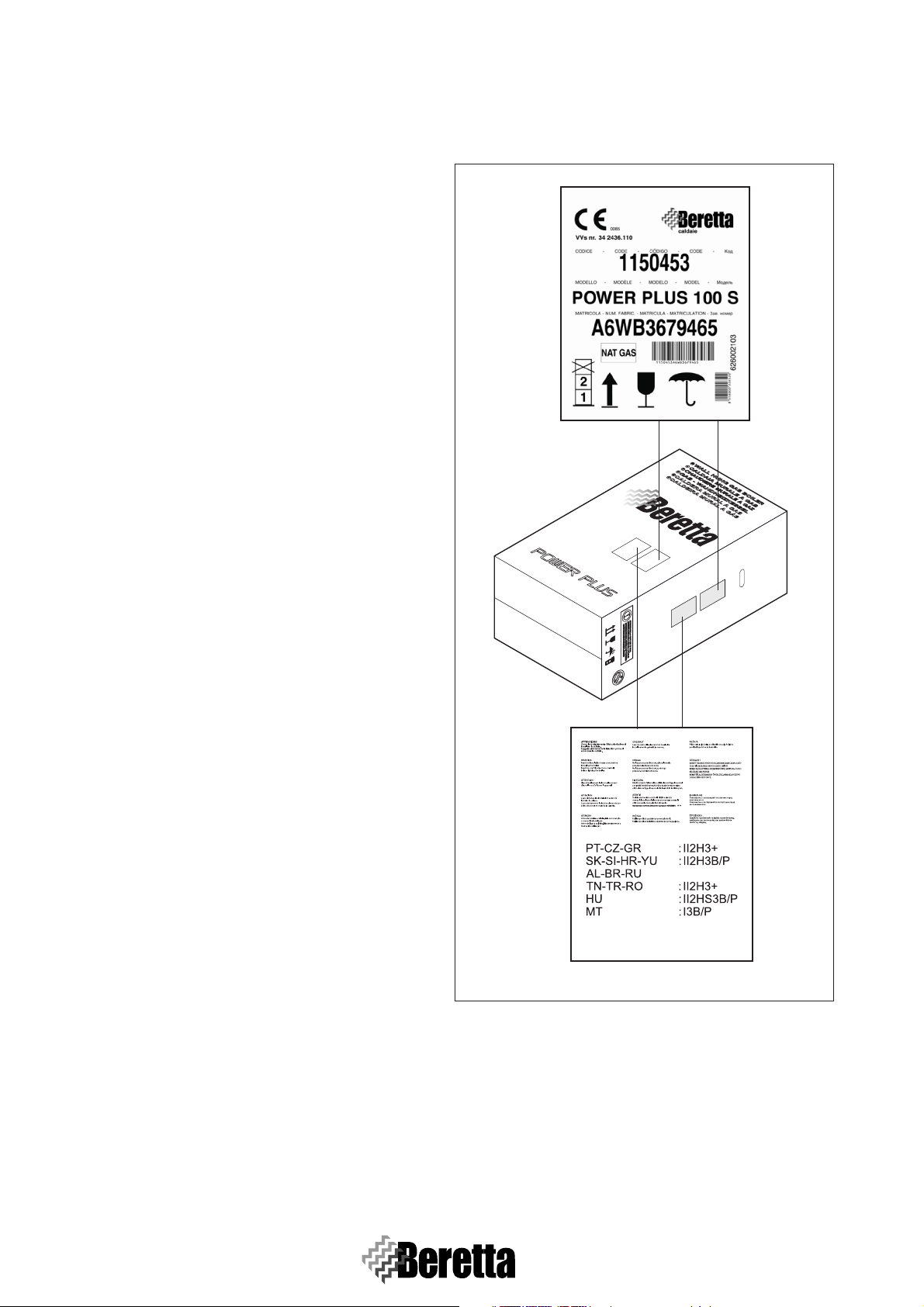
The boilers can be easily identified by:
- Packaging label (F
This shows the code, the serial number and the barcode.
IG. 1.1)
Fig. 1.1
2
1
2
Page 9
GENERAL
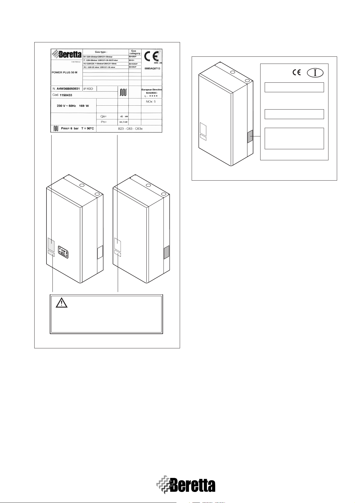
- Rating plate (FIG. 1.2)
This shows the technical and performance specifications.
100 M
100 M
100 M DEP
models
100 S
100 S DEP
models
- Gas label (FIG. 1.3)
This is applied on the side of the frame, and describes the
type of fuel used by the boiler, and the country of destination.
Paese di destinazione:
ITALIA
Tipo di apparecchio
Caldaia categoria::
Regolazione effettuata dal costruttore:
Leggere attentamente il libretto istruzioni
prima di installare e mettere in servizio
l'apparecchio.
(Later
B23, C63
II2H3+
Pressioni di alimentazione gas:
G20
20 mbar
G30+G31
28-30/37 mbar
G20 - 20 mbar - 2H METANO
ale DX)
ATTENZIONE
068120_1_E0
Fig. 1.3
If the plates or other means for clearly identifying the
product have been tampered with, removed or are
missing, the installation and servicing operations will
be much more difficult.
Fig. 1.2
Boiler regulated for:
G31 37 mbar
Destination Country:
IT
TXXXXXXXX
1.5 MAIN COMPONENTS
IDENTIFICATION
To identify the position of the described components, please
refer to the exploded diagrams reported in APPENDIX A -
PAGE 68.
For the disassembly operations, please refer to S
PAGE 35.
1.5.1 Burner
The burner (F
IG. 1.4) is completely premix, micro-flame, with
very low polluting emissions. It is inserted inside the heat exchanger to which it is mechanically assembled underneath the
fan group, by means of 4 screws.
1.5.2 Main heat exchanger
The main heat exchanger (F
IG. 1.5) is constituted by a wrin-
kled bi-metallic coil, whose external surface is made of stainless steel AISI 316L (flue side), while the inner surface is
made in copper (water side). It doesn’t need any specific maintenance operation.
1.5.3 Combustion chamber
The combustion chamber (F
IG. 1.6) has a cylindrical shape
with aluminium made headers. According to the boiler power
1 (50 kW models) or 2 (100 kW models) units are used.
ECT.5,
1.5.4 Flame ignition and detection electrode
The electrode (F
tion chamber (S
IG. 1.7) is on the left-top part of the combus-
ECT. 1.5.3, PAGE 3) and its function is to pro-
duce an high voltage spark in the proximity of the burner
(S
ECT. 1.5.1, PAGE 3) and to detect when the flame is present.
3
Page 10
GENERAL
Fig. 1.4
Burner
Fig. 1.6
Electrode
Fig. 1.5
1.5.5 Flow and return probes
The flow and return probes (F
IG. 1.8) are of NTC type and are
placed the first in the flow pipe closed to the automatic venting
device, while the second one is in the lower part of the return
pipe, closed to the draining tap. The probes allow the PCB to
read the temperature on the return and flow of the combustion
unit.
Fig. 1.7
Flow NTC
probe
Return NTC
probe
Fig. 1.8
4
Page 11
GENERAL
1.5.6 Safety thermostat
The safety thermostat (F
IG. 1.9) is manually resettable, is
placed in the upper part of the flow pipe and intervenes if the
flow temperature is above 90°C, shutting down the burner.
Safety
Thermostat
Fig. 1.9
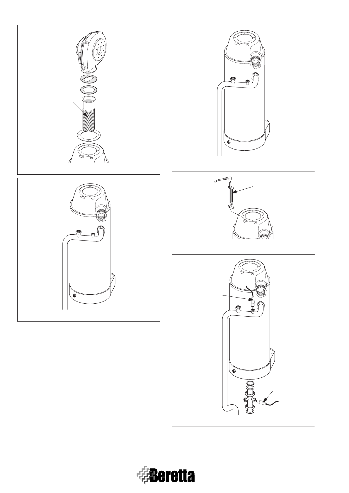
1.5.7 Flue probe
The flue probe (F
IG. 1.10) is placed in the lower part of the
heat exchanger, intervening whenever the drained flue temperature rises above 80°C.
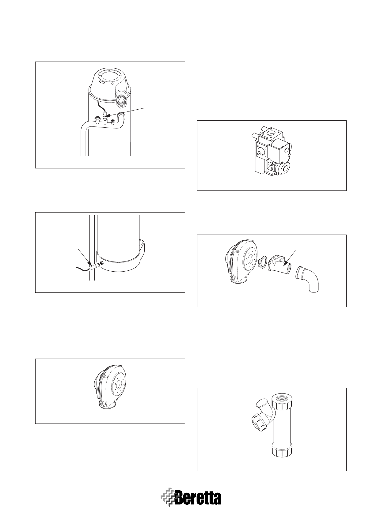
1.5.9 Gas valve
The gas valve (F
IG. 1.12) is placed in the upper part of the
combustion chamber, is connected to the venturi and is the
component that manages and checks the gas flow to the burner. The valve is made by an aluminium die-cast part with two
safety electrical valves, which are mechanically in series, but
electrically in parallel. This configuration guarantees that, in
every anomalous situation, the gas supply to the burner is interrupted in the shortest time. Removing the venturi from the
gas valve by its screws, it possible to gain accessibility to the
gas flow hole and its gasket (in case of gas supply being nat-
ural gas no injector is present).
Fig. 1.12
1.5.10 Venturi
The venturi (F
IG. 1.13) is a body made of die-cast aluminium
through which the air-gas mixture is convoyed towards the fan
and hence inside the combustion chamber.
Flue probe
Fig. 1.10
1.5.8 Fan
The fan (F
IG. 1.11) is placed in the upper part of the combus-
tion chamber and is fastened by means of screws-nuts to the
venturi (air-gas mixer) and to the body of the combustion
chamber, in which the burner is. It is used to push the air-gas
mixture towards the burner and to push the combustion products towards the flue drain collector.
Fig. 1.11
Venturi
Fig. 1.13
1.5.11 Condense collection siphon
The siphon (F
IG. 1.14) is made of composite material, is
placed in the right-bottom part of the combustion chamber, has
the function to collect and drain the condense generated by the
thermal exchange between the combustion products and the
primary water circuit, maintaining the combustion circuit separated from the condense drain circuit. Inside the siphon there
is a float that keeps separated the two described circuits even
in the case no water is present in the siphon body.
Fig. 1.14
5
Page 12
GENERAL
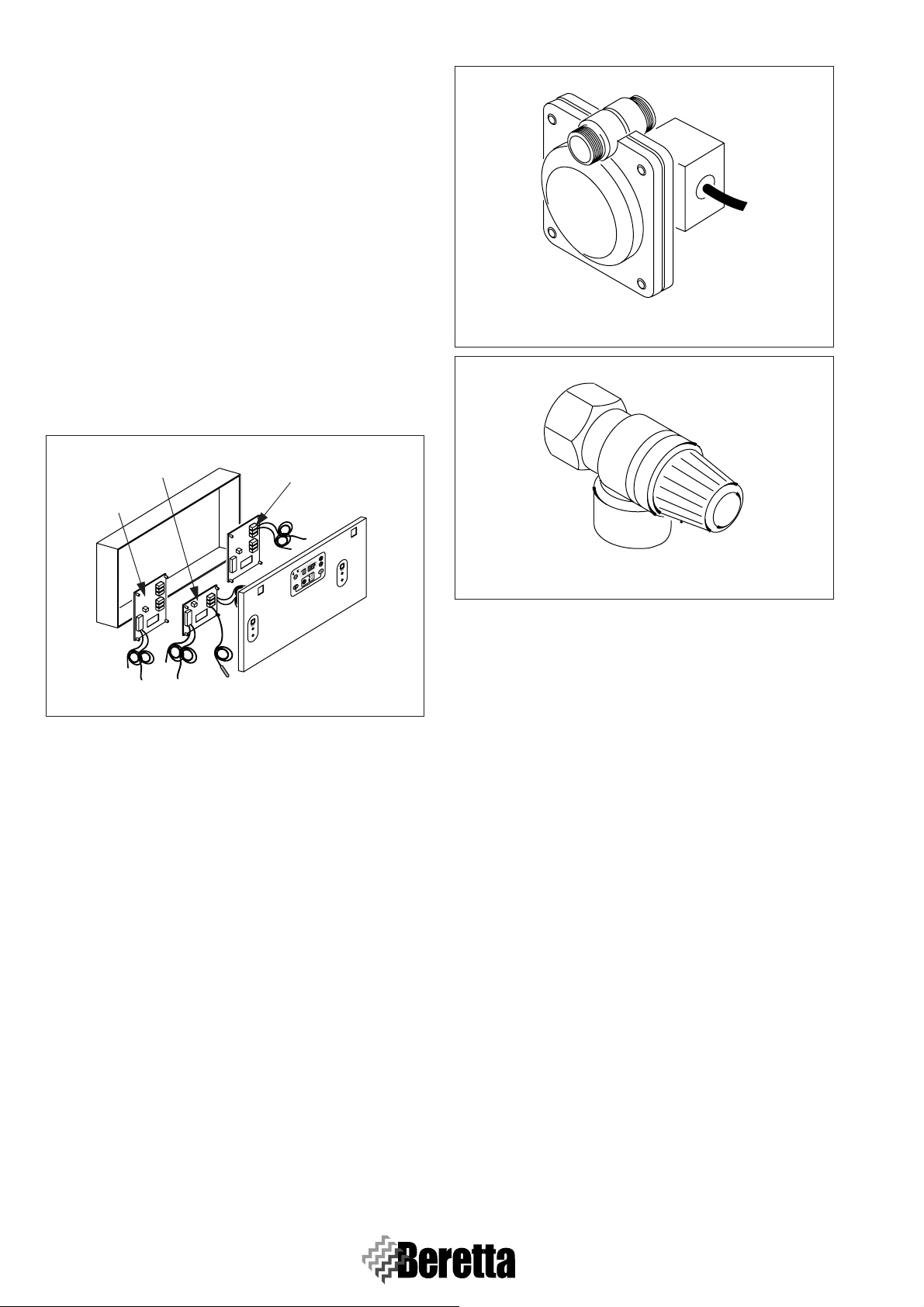
1.5.12 Control panel
The control panel (F
IG. 1.15) of the models Power Plus 50 M
– 100 M – 100 M DEP contains a master PCB and one or two
slave PCBs, according to the boiler power. The models 100 S
and 100 S DEP contain only the two slave PCBs. In the case
of cascading connection among different thermal groups, the
master PCB of the thermal unit Power plus 50 M – 100 M –
100 M DEP is able to manage via a BUS connection all the
PCBs of the units Power Plus 100 S and 100 S DEP. The management is based on a microprocessor and the self-diagnosis is
displayed by a combination of LED and display alphanumeric
digits. It is possible to cascade up to 60 thermal units managed
by the Master version thermal group with sequence rotation
and cascade strategy selection. Thanks to the versatility of the
PCB it is possible to make a very quick connection to every
kind of system for the production of hot water for the central
heating or domestic water purposes with storage tank managing, in the same time, up to three circuits working at a different
temperature.
Master PCB
Slave PCB
Slave PCB
Fig. 1.16
Fig. 1.15
1.5.13 Water differential pressure switch
The water differential pressure switch (F
IG. 1.16) is placed in
the bottom part of the thermal unit and it has the function to
check and grant a minimum flow rate of at least 500 l/h for
each thermal unit.
The boiler is brought in a safety lock-out condition whenever
the water is not present, shutting down and keeping off the
burner.
The intervention thresholds are:
- ON with system flow rate > 700/720 l/h (∆p 50/55 mbar)
- OFF with system flow rate < 540/560 l/h (∆p 35/40 mbar).
1.5.14 Safety valve
The safety valve (F
IG. 1.17) is placed on the flow pipe and is
connected to a drain pipe.
It has the task of protecting the hydraulic circuit from eventual
over-pressures consequent, for instance, to the primary fluid
volume increase caused by its heating. The valve is adjusted to
intervene at a value of 5.5 bar.
Fig. 1.17
6
Page 13
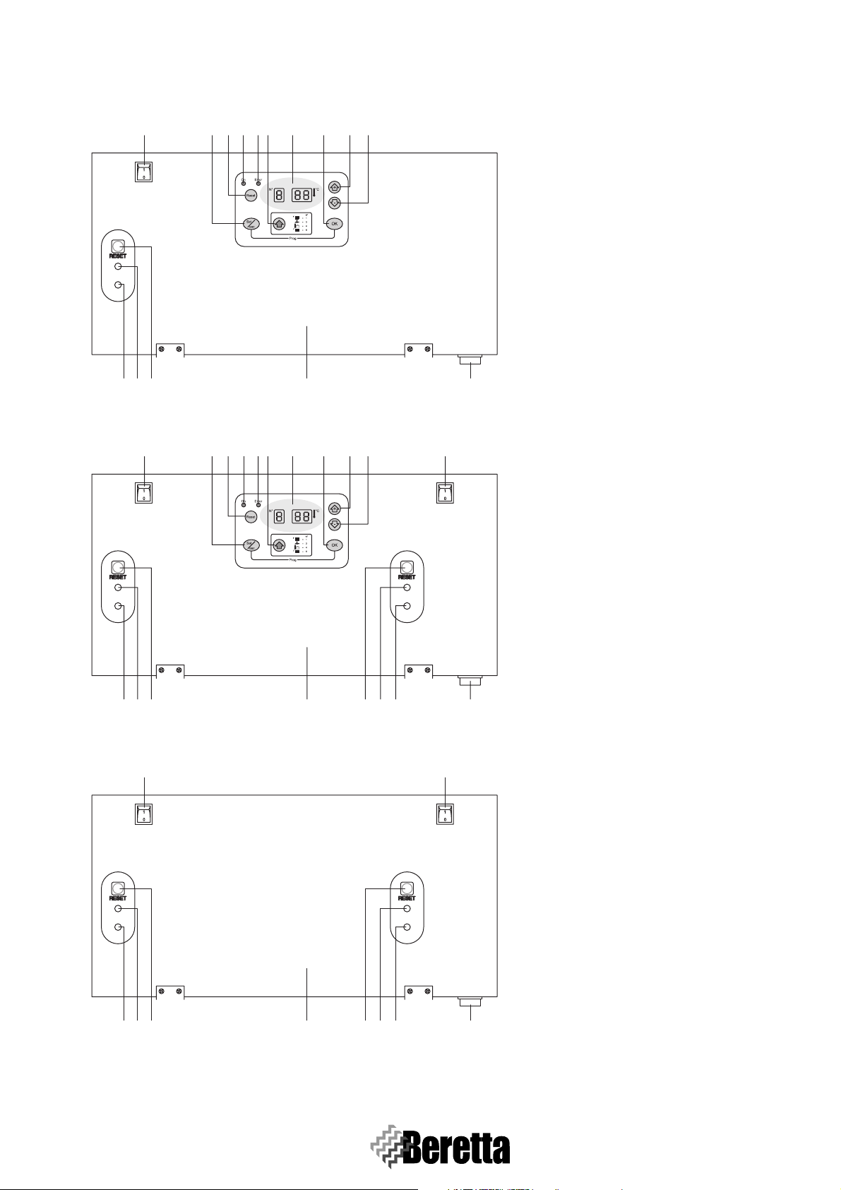
1.6 CONTROL PANELS
Power Plus 50 M
1235768109
4
GENERAL
15 1612 13 14
Power Plus 100 M
1
4
23 5 7681091 1
1 - FIRST heating unit switch
2 - Button for selecting the operating mode
3 - Reset button (Master)
4 - Electrical supply presence signal
5 - Boiler lockout signal
6 - Button for selecting the parameters
7 - Display
8 - Save button
9 - Button to increase values
10 - Button to decrease values
11 - SECOND heating unit switch
12 - Slave power supply signal:
slow flashing = stand-by
rapid flashing = ignition cycle
solid light = flame detected
13 - Slave lockout signal
14 - Reset button (Slave)
15 - Instruments panel
12
131415 1612 13 14
16 - Main boiler switch
Power Plus 100 S
1
1211131415 1612 13 14
7
Page 14
GENERAL
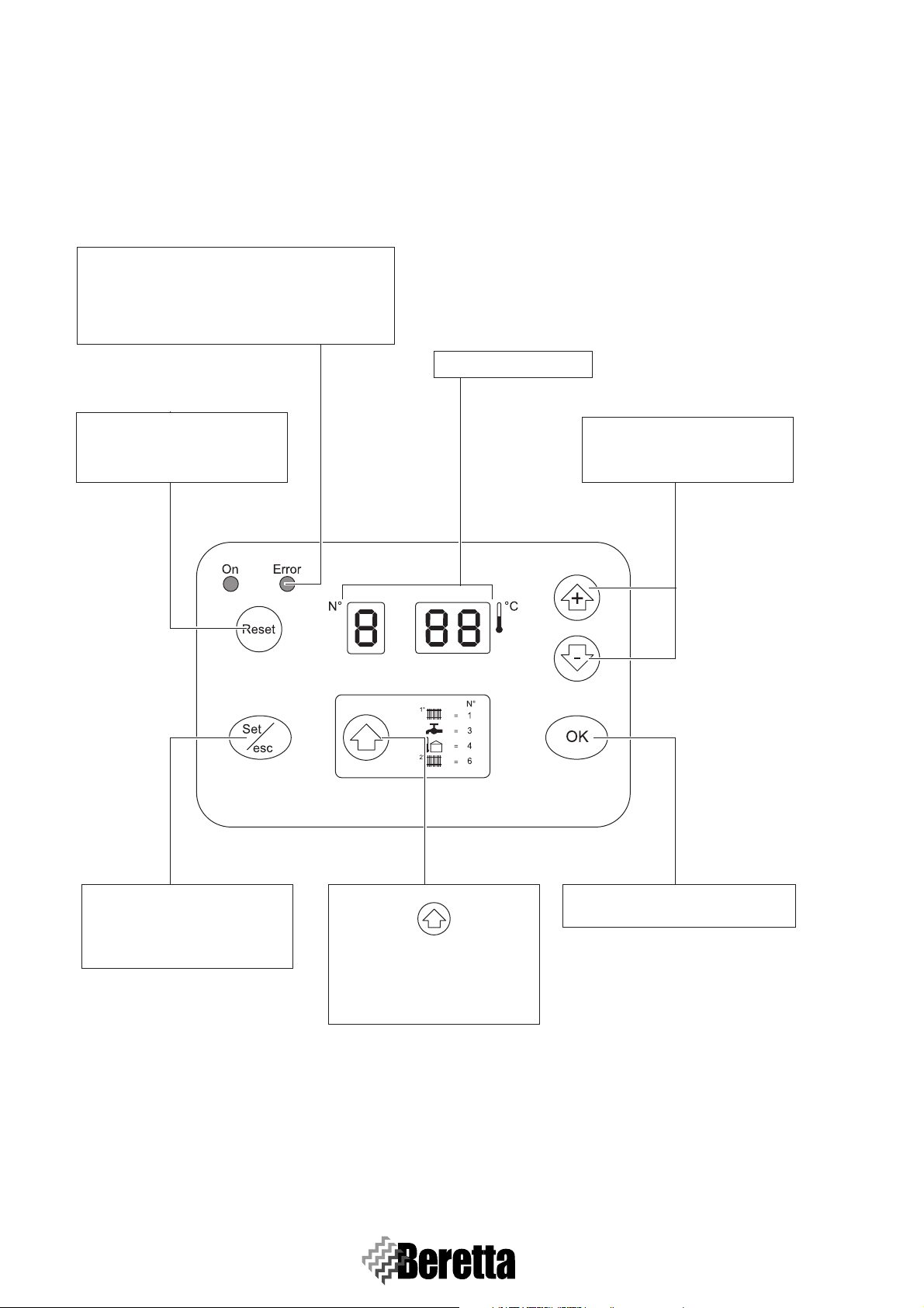
1.7 DISPLAY
The buttons on the Beretta POWER PLUS control panel have different functions in different modes. For example, the combination of two buttons corresponds to one specific function. Alternatively, a function can be activated by pressing the button briefly
or by holding it for around 5 seconds.
Red LED
This switches on only in case of anomalies that
imply the permanent lockout of a thermal unit (re-
settable only by pressing the Master or Slave Re-
set button).
7-digits display
RESET
This resets the electronic board
after a permanent lockout.
+ and -
These increase or decrease a cer-
tain value.
Set/esc
This is used to enter parameter
setting mode and monitor mode
on the individual units.
8
OK
This is used to save the new values.
This is used to display the oper-
ating status of the various cir-
cuits managed by the Master
board.
Page 15
GENERAL
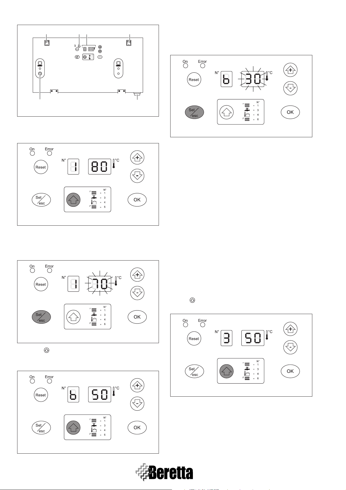
1.7.1 Display mode
The red LED comes on in the event of faults that cause the permanent lockout of a heating unit (normal operation is reset only
by pressing the Master or Slave reset button).
The 3 digits with seven segments display the status of the system:
Status of the system Display
No central heating or DHW demand.
(The two digits on the right display the flow temperature T1. E.g.: T1 = 30°C)
Demand from circuit no.1 or from circuits 1 and 2 together.
The two digits on the right display the flow temperature T1. E.g.: T1 = 80°C.
Demand from the DHW circuit or simultaneous operation.
The two digits on the right display the flow temperature T1 E.g.: T1 = 80°C.
The decimal point after the 1st digit on the left flashes.
Demand from the 2nd circuit
The two digits on the right display the flow temperature T1. E.g. T1 = 80°C.
Anti-frost function.
No request of CH or DHW.
(the two digits in the right display the flow temperature T1. E.g. T1 = 30°C)
1.7.2 Readout mode
(T
EMPERATURE VALUES AND OPERATING STATUS OF THE VARIOUS CIRCUITS)
Press the button to scroll forwards and display the values set for the individual circuits.
The values listed below will be displayed in sequence when pressing the button.
Value displayed Display
Flow temperature T1 in the high temperature circuit.
1
E.g.: T1 = 80°C.
DHW temperature T3.
2
E.g.: storage heater temperature = 50°C.
Outdoor sensor temperature T4.
3
E.g.: T4 = 7°C.
4 Flow temperature in 2nd circuit or low temperature circuit T6.
Room thermostat in the 1st circuit, closed or open.
5
OFF = contact open.
ON = contact closed.
Room thermostat in the 2nd circuit, closed or open.
6
OFF = contact open.
ON = contact closed.
0-10 V analogue input.
7
E.g.: 5.5 V, 10 V.
Operating status of the mixing valve.
8
E.g.: closing, opening, standby.
9
Page 16
GENERAL
Value displayed Display
Operating status of the main pump.
9
E.g.: pump not working, pump working.
Operating status of the DHW pump.
10
E.g.: pump not working, pump working.
Operating status of the secondary pump.
11
E.g.: pump not working, pump working.
To exit the display of the values, press the “OK” button. If no operation is performed for 5 minutes, the PCB automatically returns
to Display mode.
1.7.3 Monitor mode
From the Readout mode, press “Set/Esc” for 5 seconds to access “Monitor” mode. This mode is used to check the operating
values of each individual unit in the system (addresses from 1 to 60).
Operation Display
1 The boiler is operating with the high temperature circuit at 80°C.
Press “Set/Esc” for 5 seconds.
2
The display indicates that the values and the operating status of unit 1 can be read.
3 Press “+” or “-” to scroll and read the values for the desired unit.
Pressing the display shows the 1st value for the selected unit.
4
Pressing the button again displays the following values.
E.g.: outlet temperature 70°C.
To exit Monitor mode, press “MODE”.
5
If within 5 minutes no button is pressed or no operation is performed, Display mode resumes.
Press to display the following values for the individual unit:
Value Display
1 Flow temperature E.g.: 70°C.
2 Return temperature E.g.: 50°C.
3 Flue gas temperature E.g.: 60°C.
Ionisation current (index from 0 to 99).
4
E.g.: ionisation current index 44.
Fan PWM signal (%).
5
If PWM = 100%, this corresponds to 99 on the display.
E.g.: 66 %.
10
Flow switch open/closed (not active).
6
E.g.: contact open.
Pump or motorised valve on the individual unit on/off.
7
E.g.: Pump ON.
E.g.: Pump OFF.
Page 17

GENERAL
Value Display
Maximum ionisation current (range from 0 to 99) at first attempt.
8
E.g.: maximum ionisation current 80.
Hours of unit functioning (from 0 to 9999 hours).
9
E.g.: 8050 hours: the display reads out paired figures showing the hours in a sequence of thousands,
hundreds, tens and units.
11
Page 18
FIRST START-UP
2 FIRST START-UP
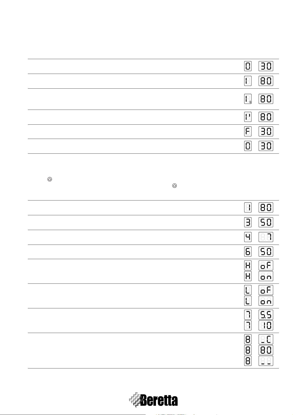
2.1 PRELIMINARY OPERATIONS
Before starting the system and running the functional tests on
the Beretta POWER PLUS boiler, check that:
- The fuel valve and valves in the central heating system are
open.
- The type of gas and the supply pressure are correct for the
boiler.
Fig. 2.1
- The system is filled, i.e. the pressure in the water circuit,
when cold, is around 1.5 bar and the circuit has been vented.
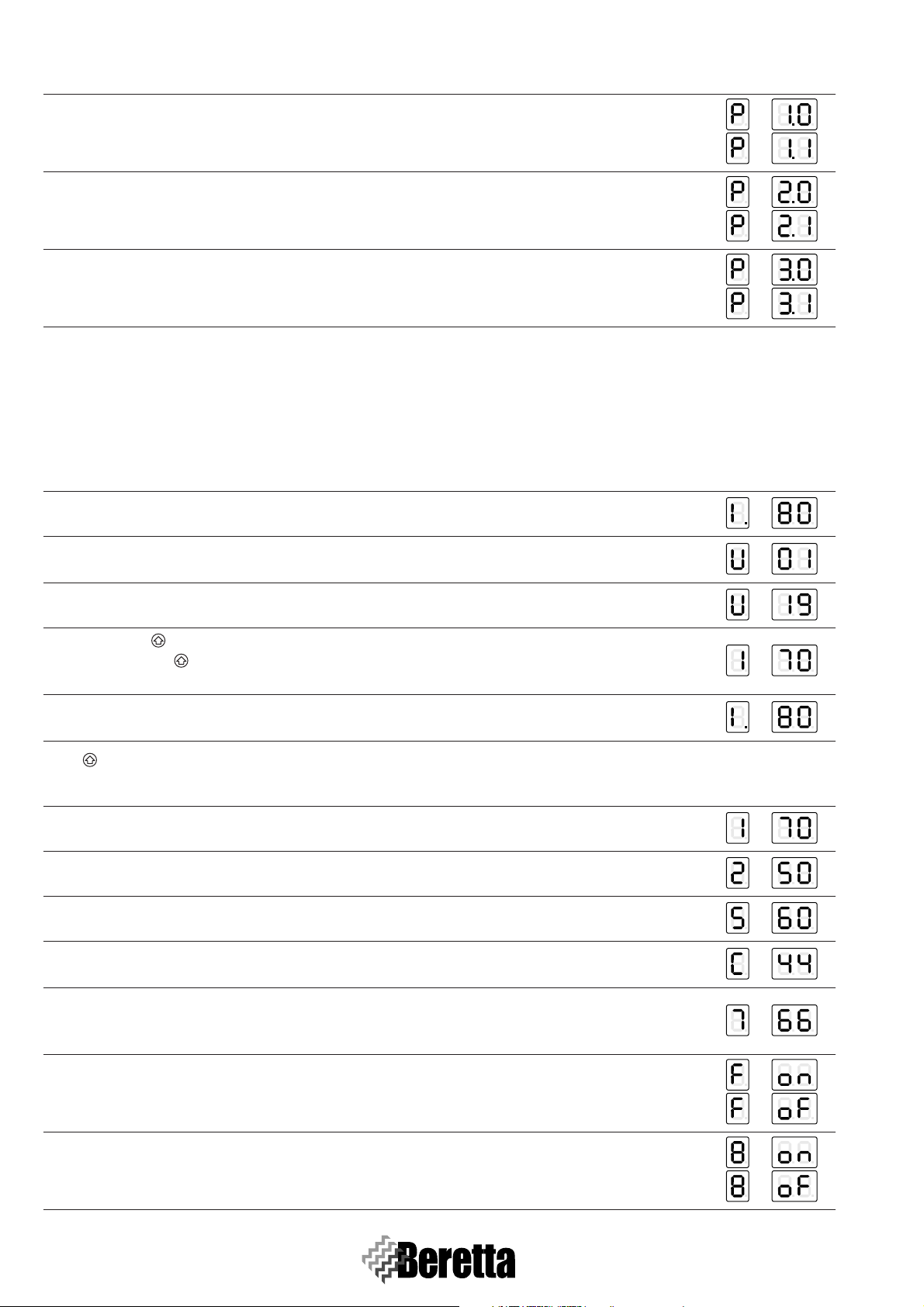
2.2.1 Filling
- Open the valves (1 - F
fittings.
ILLUSTRATIVE SCHEME
Fig. 2.4
- Open the caps on the automatic vent valve/valves (2 - F
2.5) by two or three turns.
IG. 2.4) installed on the boiler water
1
MI
RI
GAS
2
IG.
Fig. 2.2
- The system expansion vessel is suitably pre-charged.
- The electrical connections have been performed correctly.
The pumps should be connected by installing suitable
contactors with manual emergency operation.
- Check that the cap on the vent valve/valves is unscrewed.
- The pumps turn freely: loosen the inspection screw and
check with a flathead screwdriver that the motor shaft is rotating without impediments.
Fig. 2.3
Before loosening or removing the seal cap on the
pump, protect the electrical devices underneath
against water spillage.
- The flues have been properly made and installed.
2.2 SYSTEM FILLING AND DRAIN
The Beretta POWER PLUS Boiler is not fitted with a filling
valve, which must be installed on the system return.
Fig. 2.5
- If present, open the two-ways valve of each thermal engine,
setting the lever (3 - F
This lever is placed underneath the two-ways valve.
Fig. 2.6
- Open the filling valve on the system until the pressure
shown on the pressure gauge is 1,5 bar.
- Close the filling valve again.
- Bring back the two-ways valve lever (3 - F
thermal unit to its position “AUTOMATIC”.
IG. 2.6) in its position “MANUAL”.
3
AU
TO
MAN
IG. 2.6) of each
12
Page 19
The air is vented from the POWER PLUS boiler
automatically through the automatic vent valve/
valves installed on the top of the heating units. Check
that the cap on the valve is open.
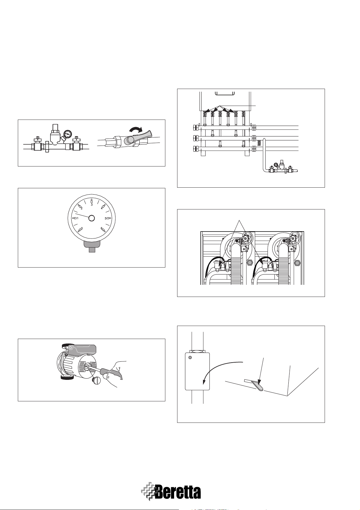
2.2.2 Drain
Before starting to empty the system, disconnect the power supply by moving the main system switch to “OFF” (F
IG. 2.7).
FIRST START-UP
1
5
MI
RI
GAS
Fig. 2.7
Emptying the BOILER
- Close the valves (1 - F
fittings.
ILLUSTRATIVE SCHEME
ON
OFF
IG. 2.8) installed on the boiler water
1
MI
RI
GAS
ILLUSTRATIVE SCHEME
Fig. 2.10
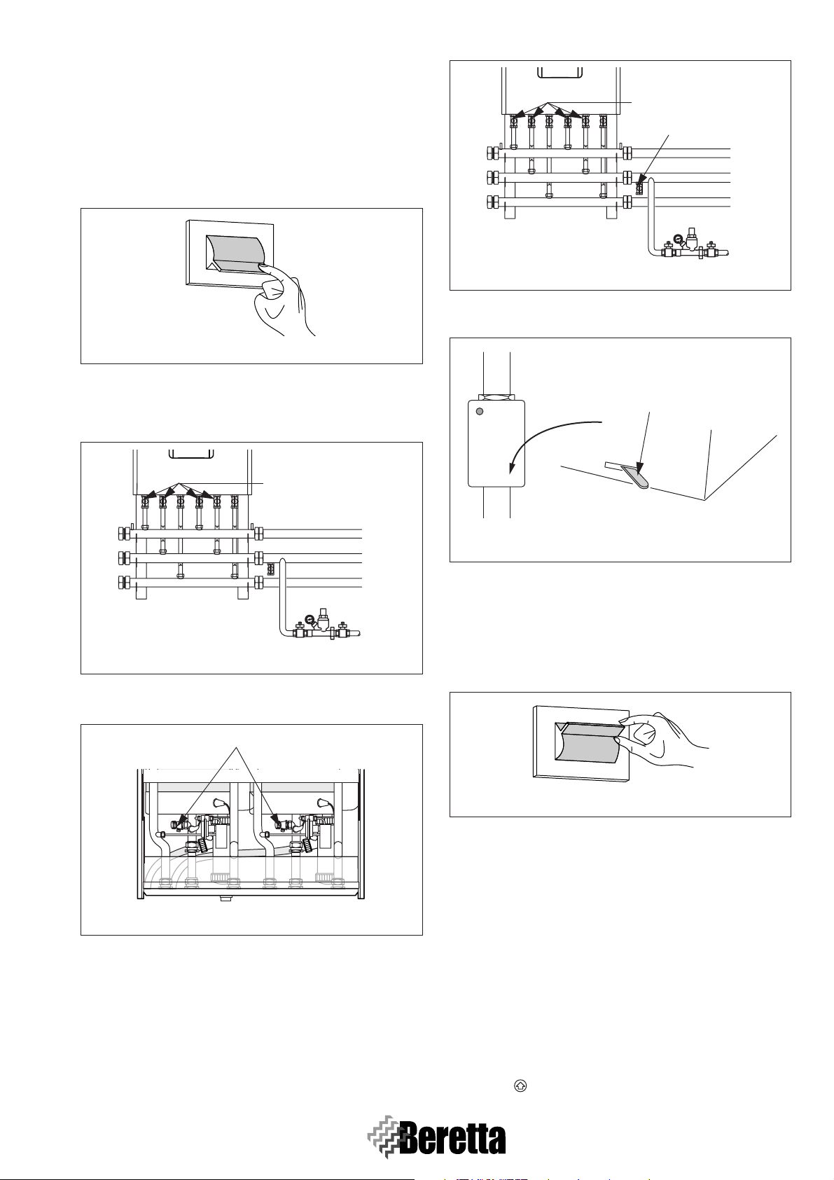
setting the lever (3 - F
IG. 2.11) in its position “MANUAL”.
This lever is placed underneath the two-ways valve.
3
AU
TO
MAN
Fig. 2.11
- Once the system has been drained bring back the two-ways
valve lever (3 - F
IG. 2.11) of each thermal unit to its position
“AUTOMATIC”.
Fig. 2.8
- Connect a plastic hose to the drain tap (4 - F
IG. 2.9), on each
heating unit, and open the tap.
4
Fig. 2.9
Before opening the drain tap (4 - FIG. 2.9) protect the
electrical devices underneath against water spillage.
Emptying the SYSTEM
- Check that the valves (1 - F
IG. 2.10), installed on the water
circuit, are open.
- Connect a plastic hose to the drain tap (5 - F
IG. 2.10), fitted
on the system return line, and open the tap.
- If present, open the two-ways valve of each thermal engine,
2.3 FIRST IGNITION
- Move the main system switch to “ON” (FIG. 2.12).
ON
OFF
Fig. 2.12
- Move the boiler main switch (1 - F
(2 - F
IG. 2.13) on each heating unit to “ON”. The green
SLAVE power supply signal (3 and 4 - F
boiler performs a self-diagnosis cycle, after which it will enter DISPLAY mode. The display (5 - F
status of the system and the temperature measured by the
probe in the “high temperature” circuit. If there are more
than two boilers installed, it is necessary to configure the addresses from the third thermal unit on. To do this, see
S
ECT. 3.12, PAGE 31 - “ADDRESSES SETTINGS FOR CAS-
CADE CONNECTIONS”.
- Set the room thermostats in the high and low temperature
zone to the desired temperature (20°C) or if the systems are
fitted with a timer-thermostat or timer, check that this is on
and set (20°C).
- Press the : button: the maximum temperature of the boiler
IG. 2.13) and the switches
IG. 2.13) flash. The
IG. 2.13) shows the
13
Page 20
FIRST START-UP
25 2
3
14
Fig. 2.13
will be displayed, that is, the maximum temperature in the
high temperature circuit, preceded by the symbol “1” (F
IG.
2.14).
Fig. 2.14
- Press “Set/Esc”: the corresponding set point will be displayed and the two digits on the right will flash. To change
the value, press “+” or “-”. To confirm press “OK” (F
IG.
2.15).
-Press “Set/Esc”: the correspondent set point will be dis-
played and the two digits on the right will flash. To change
the value, press “+” or “-”. To confirm press “OK” (F
IG.
2.17).
Fig. 2.17
For low temperature systems, select a temperature
between 20°C and 45°C. When setting the system as
“Low temperature” type, the maximum flow temperature will be automatically limited at 50°C (Parameter 23=T_CH_Low_limit).
Changing the flow temperature implies a modifica-
tion of the climatic control curve (see S
PAGE 26). These settings must only be performed by
ECT.3.11,
the Technical Assistance personnel or a suitably qualified person.
If the boiler is connected to a storage tank, set parameter 6
(pre-set to 0=no DHW service). To do this, access the “Installer programming” mode and set parameter 6 to:
- 2 = for storage heater with probe.
- 6 = for storage heater with thermostat.
In addition, set parameter 9 (DHW_Priority) to 2 for absolute
priority. If the storage tank is fitted with an NTC probe, the desired temperature can be set on the display, from 10°C to
50°C. If the storage tank is fitted with a thermostat, the desired
temperature should be set directly on the storage heater, while
the parameter 3 must be left at 50°C.
- Press button twice: the DHW temperature will be displayed, preceded by the symbol “3” (F
IG. 2.18).
Fig. 2.15
- Press the button four times: the maximum temperature in
the low temperature circuit will be displayed, preceded by
the symbol “6” (F
IG. 2.16).
Fig. 2.16
14
Fig. 2.18
-Press “Set/Esc”: the corresponding set point will be dis-
played and the two digits on the right will flash. To change
the value, press “+” or “-”. To confirm press “OK” (F
IG.
2.19). The boiler will start in DHW mode, until the demand
is satisfied.
- When the boiler is in Standby, the display on the Master unit
is in Readout mode and the three digits show the number
“1”, followed by the value of the flow temperature. The
Page 21
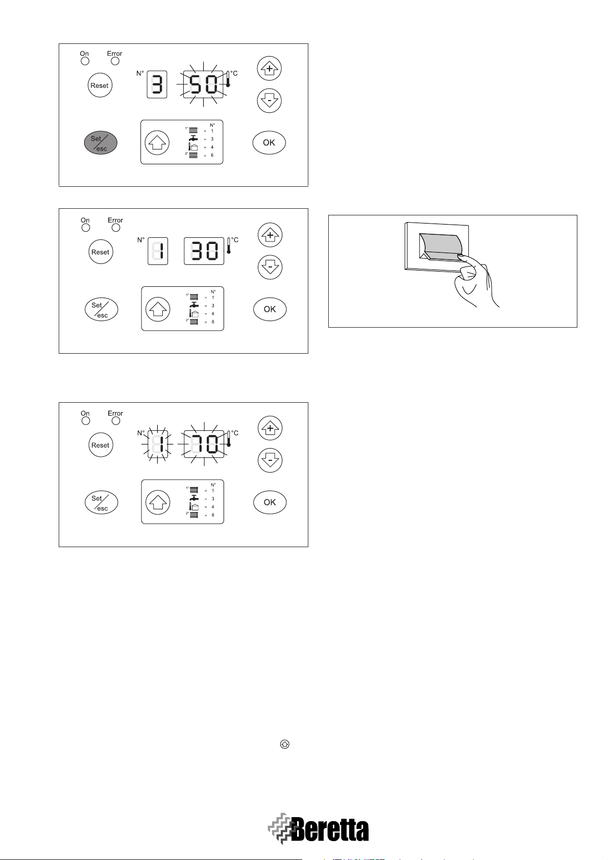
Fig. 2.19
green LED (Ref. 11, SECT. 1.6, PAGE 7) flashes.
FIRST START-UP
set correctly:
2 = storage tank with probe
6 = storage tank with thermostat
and check that its operation is correct, by opening a hot water tap.
- Check the complete shutdown of the thermal unit by moving
the main system switch to “OFF”.
- Generate an heat request operating on the Room Thermostat
or on the Time Programmer (external).
- Verify, if a storage tank is present, the DHW operation by
opening a hot water tap.
- Check the complete shutdown of the thermal unit by moving
the main system switch to “OFF”.
ON
OFF
Fig. 2.22
Fig. 2.20
- If ignition or operating faults occur on any heating unit, the
display on the Master boiler starts flashing and the red LED
(4) comes on.
Fig. 2.21
There are two possible types of errors:
- Type A errors, which can only be deactivated by pressing
the RESET button.
- Type E errors, which are deactivated when the causes are no
longer present (see S
PAGE 50).
ECT. 6.1, PAGE 50 and SECT.6.3,
After a few minutes of continuous operation controlled by the
room thermostat, the adhesives and the processing residues
will have evaporated, and the following checks can be completed:
- gas supply pressure check;
- combustion check.
2.4 CHECKS DURING AND AFTER THE
FIRST IGNITION
When ignition is complete, check that the Beretta POWER
PLUS boiler correctly:
- Starts and stops, closing the contacts on the zone thermostats.
- Displays the DHW temperature (only if the storage tank is
fitted) and central heating temperature, pressing the button twice.
Check, if the storage heater is fitted, that parameter “6” is
15
Page 22
BOILER FUNCTIONING
T_out_max
Outdoor Temperature (°C)
Flow temperature (°C)
CLIMATIC CURVE
HIGH TEMPERATURE Circuit
T_CH_High
maximum
heat need
T_CH_High_foot
T_out_min
25 20 15 10 5 0 -5 -10 -15 -20
0
10
20
30
40
50
60
70
80
90
100
3 BOILER FUNCTIONING
3.1 FACTORY SETTINGS AND
FUNCTIONAL PARAMETERS
ADJUSTMENT
Each Master PCB for each thermal group Power Plus 50 M 100 M - 100 M DEP needs to be configured according to the
system characteristics. The factory settings allow to manage
the kind of system described hereafter. In case of different
kind of systems, modify the following parameters during the
boiler installation:
- Mixed system with 2 circuit (one high temperature, one low
temperature) with thermoregulation managed by the outdoor probe (Par. 14 = 1).
- Configuration with “ring” system pump modulating on the
primary circuit (Par. 34 = 0).
- No DHW functioning (Par. 6 = 0).
- No priority between high and low temperature circuit (Par.
16 = 0)
- Maximum temperature on the high temperature circuit 70°C
(Parameter 1 user) and 40°C (Parameter 3 user) on the low
temperature one.
- Functioning with Natural gas with flues running for less
than 15 metres (Par. 31 = 1).
The functions of the central heating high temperature and low
temperature circuits and the DHW circuits can be set based on
the system requirements, by setting the functional parameters.
The first three parameters are accessible at a user level, while
the remaining parameters require the password to be entered
(“22”, vedi S
ters, press the button, after which the following values will
be displayed:.
Flow temperature in the high temperature
circuit T1
Temperature in the circuit T3
Flow temperature in the low temperature
circuit T6
To change the corresponding set points:
- Press “Set/Esc”, the corresponding value will be displayed
and the two digits on the right will flash.
- Press “+/-” until reaching the desired value. Press “OK” to
save the new value. The value displayed will stop flashing
and will be valid after 3 seconds.
EXAMPLE
Changing the low temperature Set-point from 50°c to 40°C.
ECT. 3.5.1, PAGE 19). To access the user parame-
Procedure Display
3 Press “Set/Esc”.
Press “-” to bring the set-point to the
4
intended value of 40°C.
Press “OK” to store in the memory
5
the new value.
After 3 seconds it will turn back to the Display mode with
6
the new set value.
If after having pressed
“Set/Esc” no operation is done for 10
seconds, (because the desired value corresponds to the set one)
the PCB will go back to the functioning in Display mode. If after having pressed “+” or “-” no button is pressed for the next
minute, the PCB will go back to Display mode. Should this
happen no value will be stored in memory.
3.2 CENTRAL HEATING PARAMETERS
SETTING
The following functions can be set for the CH functioning.
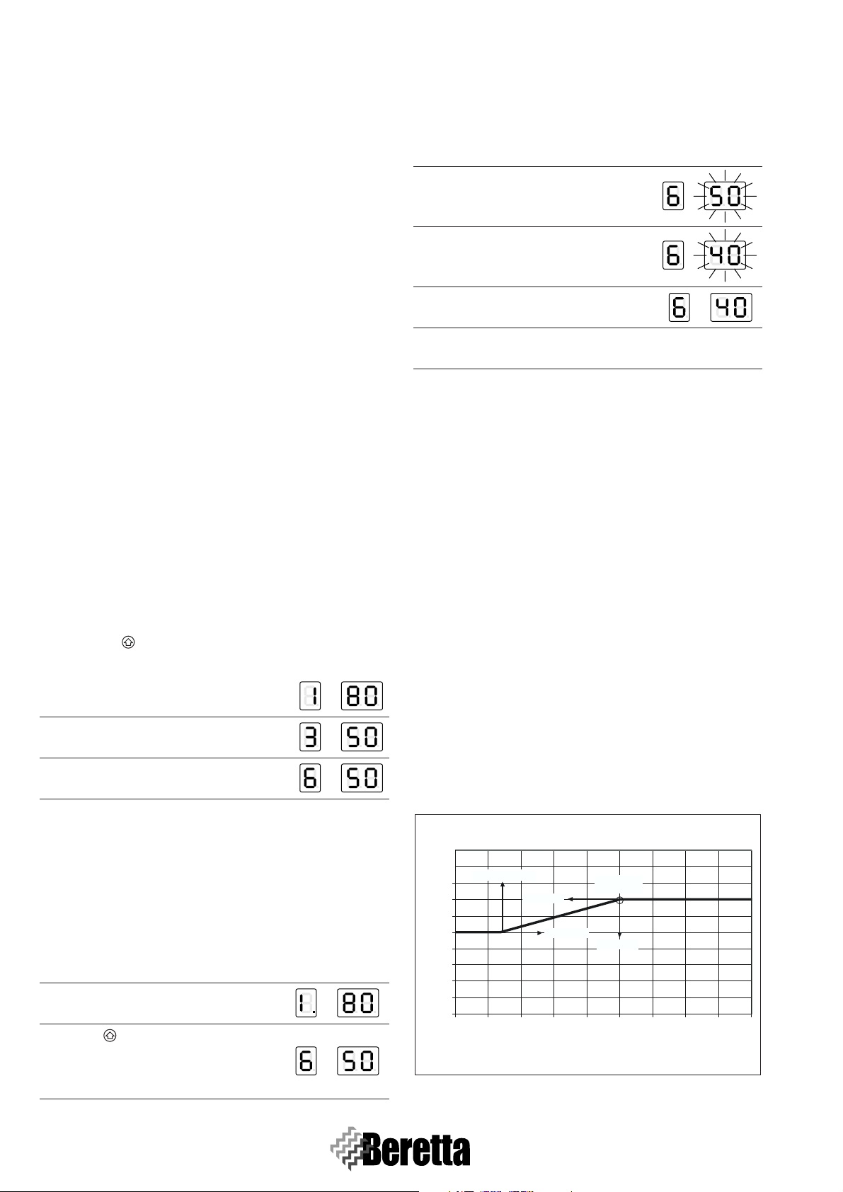
3.2.1 Setpoint_T_CH_High
Set-point in the high temperature circuit (parameter 1)
If the operating mode is set to “fixed set point” (par.
14=CH_type_high=0), this is the objective temperature. If instead the outdoor temperature probe is used, i.e. the operating
mode is set to “climate control” (par. 14= CH_type_high =1),
this is the maximum objective temperature correspondent to
the minimum outside temperature (T_out_min=par. 37, preset to 0°C). (Picture 3.1) Parameter 18 (T_CH_high_foot, preset to 50°C) defines the minimum set point correspondent to
the maximum outside temperature (T_out_max, pre-set to
18°C). Pre-set to 70°C with upper limit set by par. 17
(T_CH_high_limit, pre-set to 80°C).
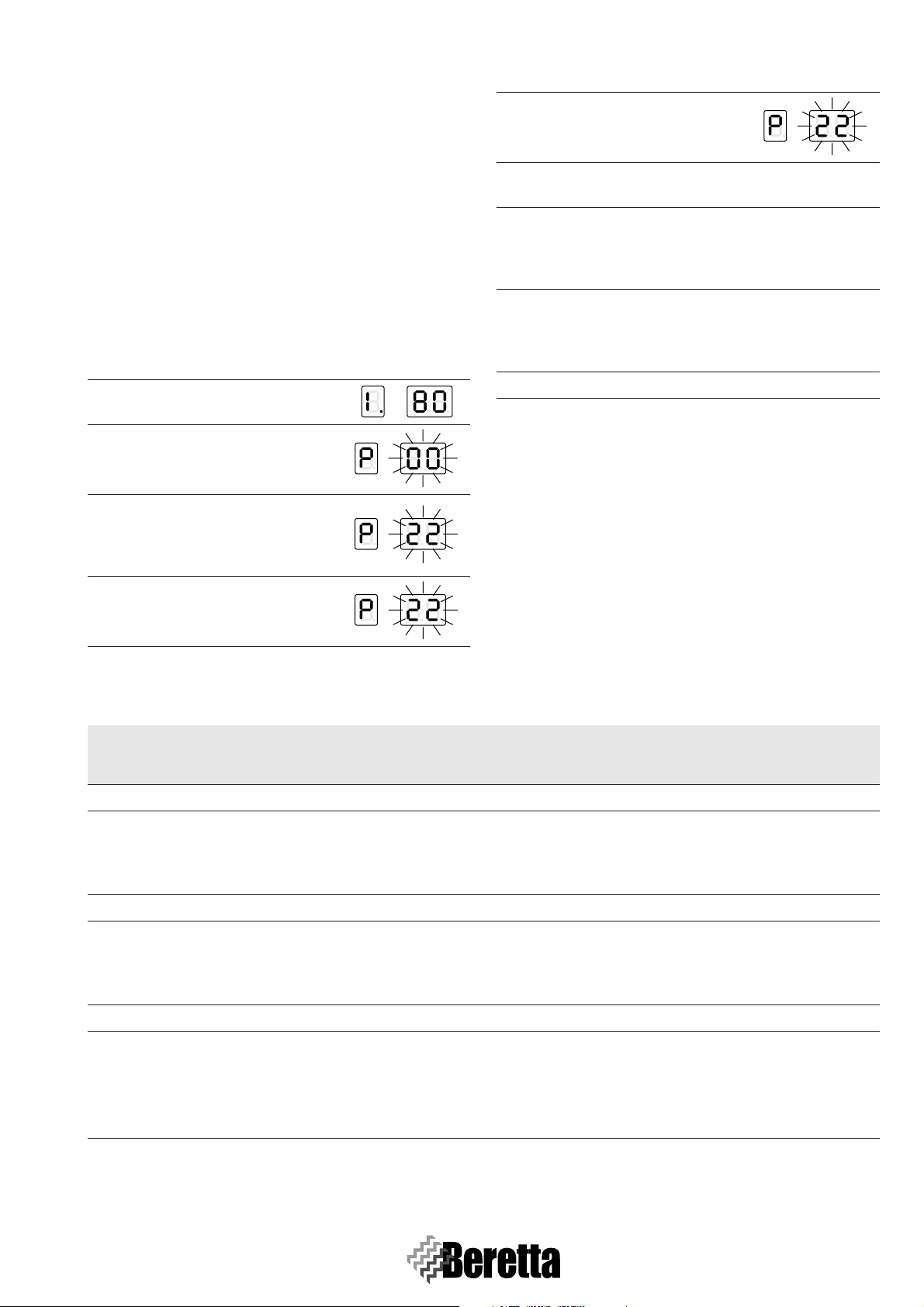
Procedure Display
Read value on the display for the high
1
temperature circuit 80°C.
Press to access the Readout mode,
press again until “6” appears on the
2
first digit to visualise the set value of
50°C.
16
Fig. 3.1
Page 23
BOILER FUNCTIONING
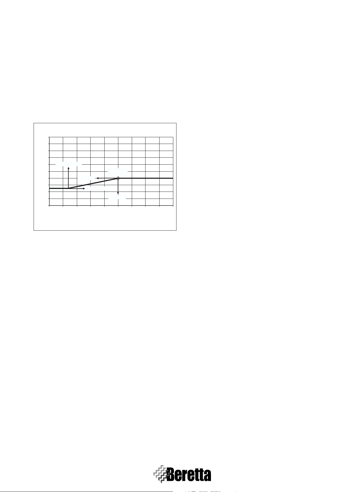
3.2.2 Setpoint_T_CH_Low
Set point in the low temperature circuit (parameter 3)
If the operating mode is set to “fixed set point” (par.
22=CH_type_low=0), this is the objective temperature. If instead the outdoor temperature probe is used, i.e. the operating
mode is set to “climate control” (par. 22=CH_type_low =1),
this is the maximum objective temperature correspondent to
the minimum outside temperature (T_out_min=par. 37, preset to 0°C). Parameter 24 (T_CH_low_foot, pre-set to 25°C)
defines the minimum set point for the maximum outside temperature (T_out_max, pre-set to 18°C). Pre-set to 40°C with
upper limit set by par. 23 (T_CH_Low_limit, pre-set to
50°C).
CLIMATIC CURVE
100
90
80
70
T_CH_Low_foot
60
50
40
30
Flow temperature (°C)
20
10
0
25 20 15 10 5 0 -5 -10 -15 -20
LOW TEMPERATURE Circuit
maximum
T_out_min
T_out_max
Outdoor Temperature (°C)
heat need
T_CH_Low
Fig. 3.2
3.2.3 CH_Priority
Central heating priority (parameter 16)
If this is set to 0 the system works without central heating priority, that is, with the high temperature and low temperature
circuit served in parallel. If set to 1, the demand from the low
temperature circuit is ignored and the corresponding pump remains off. The demand from the low temperature circuit is
only accepted when the high temperature circuit demand is absent. Vice-versa, if set to 2 the low temperature circuit has priority. Pre-set to 0.
REMARK: If a priority is selected, it will be necessary to use
the system with thermostatic setting.
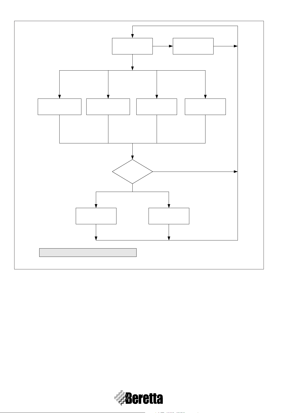
The Master can be in different operative conditions, represented by the flow diagram in F
IG. 3.3.
The diagram has been drawn with absolute DHW priority
(Dhw_Priority Par.9 = 2) and without any CH priority
(Ch_Priority Par. 16 = 0) and works with High temperature
and Low Temperature circuits working in parallel.
With CH Priority on the High Temperature circuit
(Ch_Priority Par.16 = 1), the High Temperature circuit is active whenever TA_H = 1 and DHW = 0. Under this condition
the Low Temperature circuit is not active.
With CH Priority on the Low Temperature circuit
(Ch_Priority Par.16 = 2), the Low Temperature circuit is active whenever TA_L = 1 and DHW = 0. Under this condition
the High Temperature circuit is not active.
3.3 DOMESTIC HOT WATER
PARAMETERS SETTING
The following functions can be set for the domestic hot water
circuit.
3.3.1 Setpoint_DHW
Domestic hot water set point (parameter 2)
This is the temperature value for the production of domestic
hot water. The maximum limit is set by par. 8 (T_DHW_limit,
pre-set to 60°C). Pre-set to 50°C.
3.3.2 DHW_Type
Type of storage tank (parameter 6)
- 0 = No DHW service
- 1 = Rapid heat exchanger with probe
- 2 = Storage tank with probe
- 6 = Storage tank with thermostat
For the storage tank with thermostat, if the input is a closed
contact, the domestic hot water demand is activated, if it is an
open contact the demand is not active. Pre-set to 0.
3.3.3 DHW_Priority
Domestic hot water priority (parameter 9)
- 0 = Sliding priority A
The purpose of the sliding priority A function is to allow the
system to also serve the central heating function when the
heating demand is low. The system reacts to the heating demand if:
(Setpoint_Ch - 50°C) < Manifold temp. < (Setpoint_Ch +
1°C)
Setpoint_Ch = Set point in the high or low temperature circuit, according to the request.
- 1 = Sliding priority B
The purpose of the sliding priority B function is to ensure
that the system does not stop the central heating service for
a too long time.
The system reacts to the heating request if:
(Setpoint_Dhw+T_Tank_extra) - 50°C < Manifold temp. <
(Setpoint_Dhw+T_Tank_extra) + 1°C
T_tank_extra = Par. 10 = pre-set to 30°C.
- 2 = Absolute priority (DHW service only)
Pre-set to 0.
3.4 MAIN FUNCTIONS
3.4.1 Domestic Hot Water Priority function
The domestic hot water priority function allows that when
there is demand for domestic hot water, the master board can
also serve the high or low temperature circuit.
3.4.2 Anti-frost function
The frost protection function, also active in standby, starts the
pump in the high temperature circuit and the loop pump if the
temperature in the manifold falls below 5°C. If the outdoor
probe is fitted, the pumps start if the outside temperature falls
below 3°C. If after 10 minutes the temperature in the manifold
is less than 5°C, one burner starts at maximum output, until the
17
Page 24
BOILER FUNCTIONING
TA_H = 1 &
TA_L = 0 &
DHW = 0
HIGH TEMPERATURE
CIRCUIT
TA_H = 0 or
TA_L = 1 or
DHW = 1
ERROR = 255
STAND BY
TA_H = 0 &
TA_L = 1 &
DHW = 0
LOW TEMPERATURE
CIRCUIT
TA_H = 1 or
TA_L = 0 or
DHW = 1
ERROR = 255
ERROR = 255
LOW AND HIGH
TEMPERATURE
CIRCUIT
NO
TA_H = 1 &
TA_L = 1 &
DHW = 0
TA_H = 0 or
TA_L = 0 or
DHW = 1
ERROR = 255
YES
ANTI-FROST
DHW = 1
DHW
DHW = 0
ERROR = 255
ALARM
ERROR = 255 MEANS ABSENCE OF ERRORS
Fig. 3.3
temperature in the manifold reaches 20°C. If after 10 minutes
the temperature in the manifold exceeds 5°C but the outside
temperature is less than 3°C, the pumps stay on until the outside temperature exceeds this value.
3.4.3 Dispersion function
Thanks to the dispersion function the pumps in the high and
low temperature circuits remain on for 5 minutes after the last
burner has shut down. There is a 6-minutes delay from the moment when the burner shuts down to the moment when the
two-way valve is closed or the injection pump is switched off.
When the last burner has shut down, the valve closes only
when there is no demand from the room thermostat.
3.4.4 Cascade management function
With the cascade management function is possible to select
between minimum and maximum number of burners to be
switched on to provide the power requested by the system.
ERROR
CHECK
ERROR = 255
3.4.5 Switch ON/OFF management function
In both cascading modes there is a function that limits the ignition and shutdown of the burners in the event of low heating
requirement.
3.4.6 Emergency function
In the event of faults on the Master board, there are two was of
manually controlling the Slave boards:
- By eBUS and manifold probe
Disconnect the power supply from the system, unplug the
BUS. Set the address 000000 on all the Slave boards (J10
and J17 OFF). Connect a power supply between 21 and 28
Vac to the BUS. If the Manifold Temperature < Emergency
Temp. (Par.40; pre-set to 70°C; settable between 10 and
80°C) all the burners operate at maximum output. If the
Manifold Temperature > Emergency Temp. + 5°C all the
burners are stopped.
18
Page 25
BOILER FUNCTIONING
-By PC
Disconnect the power supply from the system, unplug the
BUS and connect the PC interface. The output of the burners
can be sent directly to the Slave boards using the PC.
In the event of faults, contact BERETTA Technical
Assistance Service or a suitably qualified person.
3.5 PARAMETERS SETTING
3.5.1 Password setting
The installer parameters can be changed by entering the password (22) from the readout mode. The password for the installer level allows access to display and change the user and
installer parameters. Procedure to enter programming mode:
Procedure Display
E.g.: the outlet temperature T1 is
1
80°C.
Press “Set/Esc” and “OK”. After 5
2
seconds the second and third digit
will flash.
Use “+” and “-” to enter on the
right-hand side digit the second ci-
3
pher of the password. E.g.: password = X2.
Procedure Display
Use “+” and “-” to enter on the cen-
5
tral digit the first cipher of the password. E.g.: password = 22.
Press “OK” to confirm the password, if the password is
6
wrong the board returns to Display mode.
Press “+” and “-” to scroll the parameters enabled by the
password. Press “Set/Esc” to start setting the parame-
7
ters. The code P-XX and the corresponding value will alternate on the display.
Use “+” and “-” to change the value of the parameter.
Whenever a button is pressed, the alternating display of
8
the parameter and the corresponding value is stopped for
5 seconds and only the value is shown.
9 Press “OK” to save the new value of the parameter.
To exit installer programming mode press “Set/Esc”.
3.5.2 Parameters list
This boiler is equipped with a Master PCB that allows, via the
functional parameters setting, a superior customisation to satisfy all the system or user needs. The programmable parameters are the ones reported in the following table.
Press “OK” to save the second ci-
4
pher of the password.
N. Name
USER Parameters
1 SetPoint_ch_high 10 Par. 17 70 °C
2 SetPoint_DHW 10 Par. 8 50 °C
3 SetPoint_ch_low 10 Par. 23 40 °C
INSTALLER parameters accessible by password 22
6 DHW_type 0 6 0
limit
Lower
limit
Upper
settings
Factory
U.M. Description
If Par. 14=0 this is the high temperature circuit set
point.
If Par. 14=1 this is the maximum temperature in the
high temperature circuit.
If Par. 22=0 this is the low temperature circuit set
point.
If Par. 22=1 this is the maximum temperature in the
low temperature circuit.
0 = No DHW service
1 = Instant with NTC probe
2 = Storage tank with NTC probe
5 = Instant with flow switch
6 = Storage tank with thermostat
19
Page 26

BOILER FUNCTIONING
N. Name
7 P_DHW_max 1 255 230
8 T_DHW_limit 10 80 60 Limit for user DHW setting
9 DHW_priority 0 2 0
10 T_tank_extra 0 50 30 °C Thermal unit temperature in DHW = Par. 2 + Par. 10
11 T_tank_hyst_up 0 20 1 °C Upper DHW differential
12 T_tank_hyst_down 0 20 5 °C Lower DHW differential
13 N°_bruc_DHW 1 60 60 Maximum no. of burners in DHW
14 CH_type_high 0 3 1
15 P_ch_max 1 255
limit
Lower
limit
Upper
155
(DEP)
230
U.M. Description
settings
Factory
Maximum speed/output in DHW. The power changes
proportionally from 15 kW = 1 to 45 kW = 255. Every
point from 1 t o255 is equal to 0,12 kW. If for instance
we want to set a power of 30 kW for each thermal engine, we will insert 127.
0 = Sliding A
1 = Sliding B
2 = Absolute priority
0 = Fixed temperature
1 = Climate with outside probe
2 = 0-10 Vdc for heat output
3 = 0-10 Vdc for temperature
Maximum speed/output in CH
0 = No priority between circuits
16 CH_priority 0 2 0
17 T_CH_high_limit 10 80 80 °C Limit for user high temperature circuit setting
18 T_CH_high_foot 10 Par. 1 50 °C
19 CH_high_mod_hyst_on 0 20 7 °C Hysteresis ON for high temperature pump
20 CH_high_mod_hyst_off 0 20 3 °C Hysteresis OFF for high temperature pump
21 Attenuation_high 0 70 0 °C Set point attenuation with room thermostat open
22 CH_type_low 0 3 1
23 T_CH_low_limit 10 70 50 °C Limit for user low temperature circuit setting
24 T_CH_low_foot 10 Par. 13 25 °C
25 Attenuation_low 0 70 0 °C Set point attenuation with room thermostat open
26 CH_low_hyst_on 0 20 5 °C
27 CH_low_hyst_off 0 20 3 °C
28 Mix_valve_step_ open_time 0 255 5 s For each step the valve opens 1/2 of the set value
1 = Priority to the high temperature circuit
2 = Priority to the low temperature circuit
Min. high circuit set point at the maximum outdoor
temperature (Par. 38)
0 = Fixed temperature
1 = Thermoregulation with outdoor probe
2 = 0-10 Vdc for heat output
3 = 0-10 Vdc for temperature
Min. low temp. circuit set point - at the maximum outside temperature (Par. 38)
Hysteresis ON for low temperature circuit calculated
on the T flow Mix
Hysteresis OFF for low temperature circuit calculated
on the T flow Mix
29 Mix_valve_step_close_time 0 255 7 s For each step the valve closes 1/2 of the set value
30 Mix_valve_interval_time 0 255 5 s Mixing valve delay
31 Mixing_p_hyst 0 255 2 °C Hysteresis for maximum valve opening
32 Mixing_still_hyst 0 255 2 °C
20
Page 27

BOILER FUNCTIONING
N. Name
limit
Lower
limit
Upper
33 Power control mode 0 1 1
rd
34 3
pump 0 1 0
U.M. Description
settings
Factory
0 = Minimum number of burners
1 = Maximum number of burners
0 = System/loop
1 = Low temperature circuit
35 Frost protection -30 15 3 °C System
1 = NG with flue < 15m
36 Gas_type 1 7 1
2 = NG with flue > 15m
3 = LPG with flue < 15m
4 = LPG with flue > 15m
37 T_out_min -20 30 0 °C Minimum outdoor temperature
38 T_out_max 0 30 18 °C Maximum outdoor temperature
39 T_out_correct -30 30 0 °C Outdoor temperature correction
40 T_emergency 10 80 70 °C
41 Parameter_reset 0 1 0
42 Flow switch_si/no 0 1 1 0 = The slave does not control the pressure switch
43 Protocol 0 1 1
0 = Eco protocol
1 = Argus link (new)
MANUFACTURER Parameters (OEM) accessible by password 82
REMARK - These parameters should not be modified
44 T_ch_high_max 10 117 90 °C Upper limit for Par.17
45 P_factor_CH_high 0 255 30
46 I_factor_CH_high 0 255 70
47 D_factor_CH_high 0 255 128
48 Ch_H_block_time 0 255 0 min
Proportional Constant for the high temperature circuit
power modulation
Integral Constant for the high temperature circuit power modulation
Derivative Constant for the high temperature circuit
power modulation
When the TA_H opens the system accepts a new heat
request only after the set time
49 Postcirc_high 0 255 5 min Postcirculation of P1 (+P3)
50 T_H_correct_20° -30 30 0 °C
51 T_H_correct_85° -30 30 1 °C
52 Blocking_time_ DHW-CH 0 255 0 min
Correction of the value read by the collector probe at
20°C
Correction of the value read by the collector probe at
85°C
The burner stays OFF for the set time in the passage
from DHW to CH
53 T_ch_low_max 10 90 80 °C Upper limit of the Par. 23
54 P_factor_CH_low 0 255 30
55 I_factor_CH_low 0 255 70
56 D_factor_CH_low 0 255 128
Proportional Constant for the low temperature circuit
power modulation
Integral Constant for the low temperature circuit power modulation
Derivative Constant for the low temperature circuit
power modulation
57 Ch_L_block_time 0 255 0 min
58 T_dhw_max 10 117 80 °C
59 P_factor_DHW_istantaneous 0 255 30
21
Page 28

BOILER FUNCTIONING
N. Name
limit
Lower
limit
Upper
U.M. Description
settings
Factory
60 I_factor_DHW_istantaneous 0 255 70
61 D_factor_DHW_istantaneous 0 255 128
62 P_factor_DHW_storage 0 255 30
63 I_factor_DHW_storage 0 255 70
64 D_factor_DHW_storage 0 255 128
65 Dhw_&_ch_hysterese_up 1 80 1
66 Dhw_&_ch_hysterese_down 1 80 50
67 T_tank_hyst_down_2 0 20 5
68 T_tank_hyst_up_2 20 3
69 Postcirc sanitary 0 255 3 m
70 Hyst_up_reduce_burner 0 20 2 °C
71 Hyst_down_add_burner 0 20 5 °C
72 Hyst_up_quick_stop 0 80 4
73 Hyst_down_quick_start 0 80 70
74 Quick stop time 0 255 2 s
75 Quick start time 0 255 2 s
Wai time after
76
burner_switched
025530 s
77 Cycle_limitation 0 1 0
78 Cycle_limit_stop 0 255 60
79 Cycle_limit_inc 0 50 10
80 Cascade Rotation 0 255 24 h
81 Flow Switch 0 1 0
82 Return probe 0 1 1
83 Maximum_fan_speed_slave 20 70 57 rpm
84 Minimum_fan_speed 20 Par.83 25 rpm
85 Ignition_fan_speed Par.84 Par.83 45 rpm
86 Prepurge_fan_speed Par.84 Par.83 45 rpm
87 Max flow temperature 10 117 90 °C
88 Max return temperature 10 117 80 °C
89 Max flue temperature 10 117 80 °C
90 Flue Temperature Safety 0 1 0
91 T.max flow/return Safety 0 1 0
Pump postcirculation/slave
92
valve
02556 m 255 = Continuous functioning
93 D_max_flow_return 10 99 35 °C
94 Postcirculation 3
rd
pump 0 255 5 m 255 = Continuous functioning
0 = NO flow switch
1 = YES flow switch
0 = NO return probe
1 = return probe present with control on ∆T
0 = Volatile lockout
1 = Permanent lockout
0 = Volatile lockout
1 = Permanent lockout
∆ > Par.93: OFF
∆ > Par.93 - 5°C: Minimum
∆ > Par.93 -10°C: Power reduction of 60°C.
22
Page 29
BOILER FUNCTIONING
N. Name
limit
Lower
limit
Upper
U.M. Description
settings
Factory
95 Password 00 99 22-44 DO NOT MODIFY
96 Hyst_up_PID_I_reduce 0 10 1
If T.flow ≥ setpoint + Par. 96, the Par. 97 is deducted
97 I_reduce_value 0 30 1 s
from the high bit of the sums of the differences from
the set. Reduction of the fastest integral factor
98 Low_load waiting 0 255 60 s
Waiting time of the Master to recognise the low load
condition
Waiting time to enable the low load condition. The low
99 Low_load period 0 255 60 °C
load condition is active if the T.flow is above the set
temperature with PAR. 9B and remains high after the
time set with Par. 99.
9A Neg_delta2_T 0 20 8 °C
9B Calc_neg_delta 0 1 1
9C Neg_delta2_T 0 30 0 °C
9D Low_load_∆ 0205 °C
9E Hyst_∆_mand/rit. 0 5 2 °C
This is used to reset the burners power when T.flow <
setpoint - Par. 9A
0 = Calculation low load from 85°C
1 = Calculation low load from set-point
It is used to reduce the burners power when T.mand ≥
Setpoint - Par. 9C. the power reduction is 60/1°C
The low load condition is active with T.flow > Setpoint
+ Par. 9D
Hysteresis of Par. 93: the burner is switched off with ∆
> Par. 93 and is switched on when ∆ < Par. 93- Par. 9E
3.6 SETTINGS
The POWER PLUS Boiler is supplied for operation on G20
(natural gas), as indicated on the rating plate, and has already
been adjusted in the factory by the manufacturer. If, however,
the adjustments need to be performed again, for example after
special servicing operations, the replacement of the gas valve,
or alternatively following the conversion from G20 to G30G31 or vice-versa, proceed as follows.
The adjustments at maximum and minimum output
must be carried out in the sequence described, and
only by BERETTA Technical Assistance or qualified
personnel authorised by BERETTA.
TEST mode
In Test mode, a high temperature heating demand can be generated corresponding to maximum and minimum power. All
the system fans must be activated. If the installer switches off
some of the Slaves, the others, connected to the Master, must
continue operating.
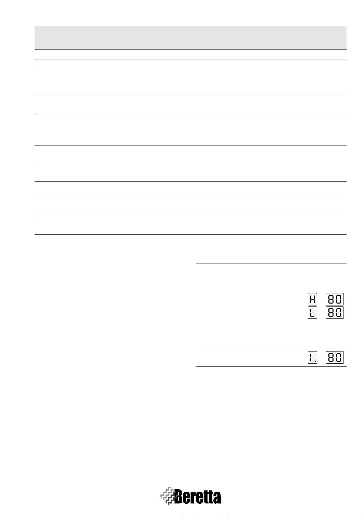
To enter Test mode from Display mode, proceed as follows:
Procedure Display
Press “Set/Esc” and “+” at the same
time per 5 seconds. After 5 seconds the
maximum or minimum speed can be selected using the “+” and “-” buttons.
All the system fans will operate at the
selected speed. The first digit will show
1
the selected speed:
H = maximum speed
L = minimum speed
The other two digits will show the out-
let temperature. E.g.: T1 = 80°C.
Press “OK” to exit Test mode and re-
2
turn to Display mode.
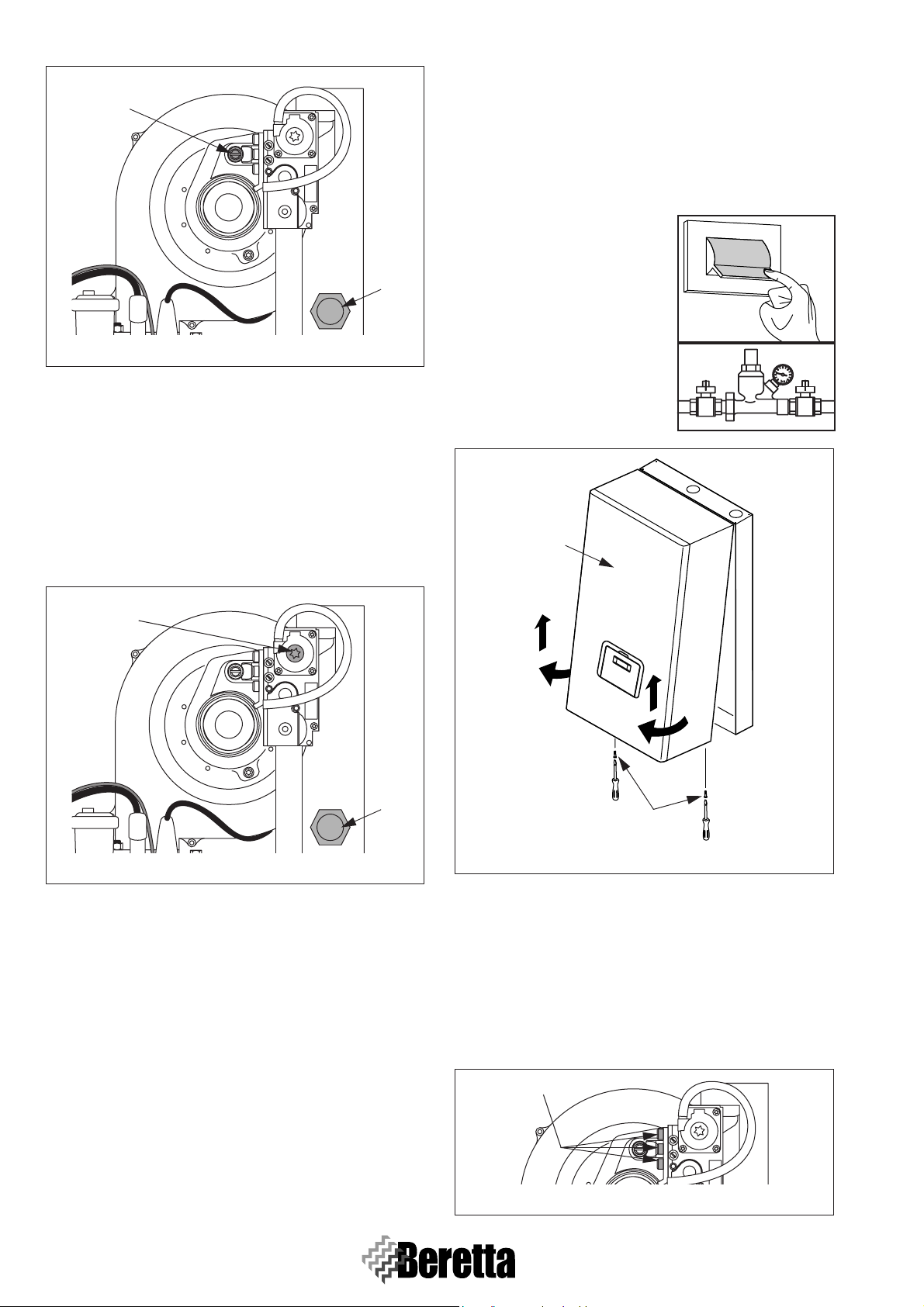
3.6.1 Maximum power CO
2 setting
- Press the “Set/Esc” and “+” buttons together for 5s.
- Start the boiler by the room thermostat (close). The boiler
will operate at maximum output showing “H” on the display, followed by the flow temperature (chimney sweep
function).
- Unscrew the protective cap (1 - F
IG. 3.4) with a socket
wrench of 10mm and insert the combustion analyser probe.
- Adjust the CO
(2 - F
IG. 3.4) located on the fan assembly (turning clock-
wise decreases the CO
2 using a screwdriver on the adjustment screw
2 value), so as to achieve a value of
9.4% for G20 and 10.7% for G30-G31.
23
Page 30
BOILER FUNCTIONING
2
The conversion must only be carried out by BER-
ETTA Technical Assistance or qualified personnel
authorised by BERETTA, even when the boiler is
already installed.
Once the conversion has been completed, set the
boiler again as described in S
ECT.3.6, PAGE 23.
Before performing the conversion:
- Disconnect the power supply
from the appliance by moving
ON
the main switch to “OFF”.
1
Fig. 3.4
3.6.2 Minimum power CO2 setting
- Press the “Set/Esc” and “-” buttons together for 5s. The
boiler will operate at minimum output showing “L” on the
display, followed by the flow temperature.
- Remove the protective cap on the gas valve by using an
Allen key (5 mm). Adjust the CO
on the adjustment screw (3 - F
sembly (turning anticlockwise decreases the CO
2 using the same Allen key
IG. 3.5) located on the fan as-
2 value),
so as to achieve a value of 8.4% for G20 and 8.7% for G30G31.
3
- Close the fuel general valve.
To fit the kit:
- Unscrew the fastening screws (1
- F
IG. 3.6) on the front panel (2 -
F
IG. 3.6).
2
OFF
1
Fig. 3.5
3.6.3 Adjustments verification
Press the “Set/Esc” and “+” buttons together for 5s and check
the max CO
2 value (9.4% for G20 and 10.7% for G30-G31).
Then press the “Set/Esc” and “-” buttons for 5s and check the
min CO
2 value (8.4% for G20 and 8.7% for G30-G31).
After having completed the checks:
- Stop the chimney sweep function by pressing “OK”.
- Adjust the thermostat (open) so as to stop the boiler.
- Remove the analyser probe and carefully retighten the flue
test point cap (1 - F
IG. 3.5) with a socket wrench of 10 mm.
3.7 GAS CONVERSIONS
The POWER PLUS Boiler is supplied for operation on G20
(natural gas). However, it can be converted for operation on
G30-G31 (LPG), using the special kit supplied.
1
Fig. 3.6
- Pull the base of the panel (2 - F
IG. 3.6) outwards and then
upwards to release it from the frame and then remove it.
- Set parameter 36 to 3 or 4, according to the length (L) of the
flue:
• 3 = L < 15 m
• 4 = L > 15 m.
The fan speed is adapted automatically.
- Disassemble the gas valve from the fan assembly by loosening the three screws (3 - F
IG. 3.7).
3
Fig. 3.7
24
Page 31

- Locate the gas passage hole and seal. If the system is Natural
6.5
Gas fuelled, there is no diaphragm.
- Insert the calibrated diaphragm (4 - F
IG. 3.8) supplied inside
the kit, marked with “6.5” without removing the seal. Only
if the boiler is supplied by a mixture of gases that causes ignition problems, use the other supplier diaphragm (5 - F
IG.
3.8) marked with “6.75”.
6.75
4 5
Fig. 3.8
- Reassemble the gas valve.
- Apply the sticker (6 - F
IG. 3.9) for G30-G31, supplied inside
the kit, on the inside of the panelling, and remove the sticker
for G20.
- Remove the sticker for G20 placed on the side of the frame.
BOILER FUNCTIONING
2
1
Fig. 3.10
6
Boiler regulated for:
G31 37 mbar
Destination Country:
TXXXXXXXX
IT
Fig. 3.9
After having installed the kit make sure that:
- All the joints made are tight.
- All the calibration operations described in S
PAGE 23 have been completed
ECT.3.6,
3.8 BURNER PRESSURES SETTINGS
3.8.1 Gas supply pressure check
- Move the main system switch to
“OFF”.
- Unscrew the fastening screws (1
- F
IG. 3.10) on the front panel (2
- F
IG. 3.10).
- Pull the base of the panel (2 -
F
IG. 3.10) outwards and then up-
wards to release it from the
frame and then remove it.
- Unscrew the screw on the pressure test point (3 - F
located upstream of the gas valve by around two turns, and
connect a pressure gauge.
ON
OFF
IG. 3.11),
3
Fig. 3.11
- Power-up the boiler by
moving the main system
ON
switch and the main
switch/switches on the appliance to “ON”.
OFF
In TEST mode, a high temperature heating request at maximum output can be generated.
To do this:
- Press the “Set/Esc” and “+” buttons together for 5 seconds.
- Start the boiler by adjusting (close) the room thermostat.
The boiler will operate at maximum output showing “H” on
the display, followed by the flow temperature (chimney
sweep function).
Fig. 3.12
25
Page 32

BOILER FUNCTIONING
- Check that with the burner on at maximum output the gas
pressure is the rated supply pressure, as shown in the table.
Description G20 G30 G31
Wobbe index 45,7 80,6 70,7 MJ/m
Rated supply pressure 20 28-30 37 mbar
- Adjust the thermostat (open) so as to stop the boiler.
- Press “OK” to exit TEST mode.
- Disconnect the pressure gauge and tighten the screw on the
pressure test point (3 - F
IG. 3.11) upstream of the gas valve.
3.9 COMBUSTION CHECK
- Power-up the boiler by
moving the main system
switch and the main
switch/switches on the appliance to “ON”.
In TEST mode, a high temperature heating request at maximum output can be generated.
To do this:
- Press the “Set/Esc” and “+” buttons together for 5 seconds.
- Start the boiler by adjusting the room thermostat (close).
The boiler will operate at maximum output showing “H” on
the display, followed by the flow temperature (chimney
sweep function).
Fig. 3.13
- Combustion can be checked by unscrewing the protective
cap (4 - F
ing the analyser probe in the available position.
REMARK: Once the set-point has been reached, the boiler
- Once having completed the check, stop the chimney sweep
function by pressing “OK”.
- Adjust the thermostat (open) so as to stop the boiler.
- Remove the analyser probe and carefully retighten the protective cap (4 - F
mm.
REMARK: Perform the check on each thermal engine.
Fig. 3.14
IG. 3.14) with a socket wrench of 10mm and insert-
will modulate its power.
IG. 3.14) by means of a socket wrench of 10
ON
OFF
4
3.10 FAN SPEEDS
The fan speed is adjusted automatically based on the type of
gas and the length of the flue (L). This information is managed
by parameter 36. To modify it:
3
- Enter “INSTALLER PROGRAMMING MODE” following
the procedure described in S
rameter 36 to:
1 = natural gas and L<15 m
2 = natural gas and L>15 m
3 = GPL e L<15 m
4 = GPL e L>15 m.
The POWER PLUS boilers are supplied for operation with
G20 (natural gas), with a flue L<15m (parameter 36=1).
Once the checks are complete, replace the front panel and secure it using the same screws removed before.
All the check must only be carried out by BERETTA
Technical Assistance or qualified personnel authorised by BERETTA.
ECT. 3.5, PAGE 19 and set pa-
3.11 THERMOREGULATION SETTINGS
3.11.1 Central heating high temperature circuit
functioning
The burner delay time of the circuit of high temperature
(Ch_high_blocking_time; Par.48 OEM pre-set 0; adjustable
between 0 and 255min) is the time between two successive
burner ignitions during an heat request of the High Temperature circuit. The delay time is active only when the OFF of the
burner is caused by the hysteresis and not for the room thermostat TA_H opening. The delay time is not active in case of heat
request of the DHW circuit.
In this state the power requested by the Master to the Slaves
changes linearly between 1 and the parameter of the Maximum Power in CH (P_ch_max; Par.15 pre-set 230 for the
models 50 M - 100 M - 100 S, pre-set 170 for the models 100
M DEP - 100 S DEP; adjustable between 1 minimum power
and 255 maximum power).
3.11.2 Attenuation_High
Attenuation function for the HIGH TEMPERATURE circuit (parameter 21)
Two cases are possible:
- Operation with fixed set point, Par. 14=0.
- Operation with climate control Par. 14=1.
Operation with fixed set point, PAR. 14=0
- With attenuation in the high temperature circuit disabled,
Par. 21=0, when the thermostat in the high temperature circuit closes, the heating demand is enabled. When opening,
the system stops.
- The Master controller activates the pump in the high temperature circuit PZ1 and the loop pump PZ2 (configuration with
loop circuit pump), if the parameter for the third pump is set
to 0 (Par. 34=0), otherwise the third pump remains off.
- The set point for the high temperature circuit can be set on
the Master controller, Setpoint_T_CH_High = Par. 1, preset to 70°C, settable in the range from 10°C to
T_CH_high_limit=Par 17, in turn pre-set to 80°C. The set
point used will be the value set for parameter 1.
26
Page 33

BOILER FUNCTIONING
- The burner is on when: Manifold Temperature ≤ Set point Start hysteresis.
- The hysteresis ON can be set, CH_High_mod_hyst_on =
Par. 19, pre-set to 7°C, settable between 0 and 20°C. The
Master controller converts the heating request into a power
requirement for each slave controller.
- The burners are off when: Manifold Temperature ≥ Set point
+ Hysteresis OFF.
- The hysteresis OFF can be set (CH_High_mod_Hyst_off =
Par. 20, pre-set to 3, settable between 0 and 20°C).
- When the attenuation in the high temperature circuit parameter is enabled, Par. 21 ≠ 0, the contact on the high temperature circuit thermostat is ignored, and a request for heat in
the high temperature circuit is present when: Manifold Temperature ≤ Set point - Start hysteresis.
- The demand for heat is interrupted when: Manifold Temperature ≥ Set point + Stop hysteresis.
- The set point in this case coincides with the value set for parameter 1 (Setpoint_T_CH_High), if the contact of the high
temperature circuit thermostat is closed, while it is calculated as the value set for parameter 1 minus the attenuation
(Setpoint_ T_CH_High-Attenuation_high) if the contact is
open.
- If no heat request is present form the Low Temperature circuit, the mixing valve is closed and the power requested to
the Slave controllers is calculated through the PID control of
the high temperature circuit (PID_CH_high:
P_factor_CH_high; Par.45 OEM pre-set to 30; settable from
0 to 255; I_factor_CH_high Par.46 OEMpre-set to 70; adjustable from 0 to 255; D_CH_high Par.47 OEM pre-set at
128, programmable from 0 to 255) applied to the selected
set-point (Setpoint_ch_high; Par.1) and to the collector temperature.
- The power requested to each Slave controller is also dependent from the cascading strategy selected.
- When the room thermostat TA_H opens, the heat request
ceases, the burner is switched off and the High Temperature
pump P1 continues to run for the post-circulation time
(Postpump_ch_high; Par.49 OEM pre-set 5 min; settable
between 0 and 255 min). if the parameter 3rd_pump Par.34
is set to 0 (system pump) the third pump, as well, continues
to function along the post-circulation time. If present the injection pump, or the 2-ways valve, they are supplied for the
post-circulation time only.
Operation with climate control, Par. 14=1
If the attenuation in the High Temperature circuit parameter is
equal to 0, Attenuation_high=Par. 21=0, the behaviour is the
same as in the previous paragraph, except for the set point being calculated according to the outside temperature.
- If the outside temperature = T out_min=Par. 37, pre-set to
0°C, then set point =setpoint_T_Ch_high.
- If the outside temperature = T out_max=Par. 38, pre-set to
18°C, then set point = T_CH_high_ foot=Par. 18, preset to
50°C.
Between the two outside temperature values, the set point is
calculated linearly.
The outside temperature is measured between -30°c and 98°C
and can be amended with the parameter T_out_correct (Par.
39 pre-set to 0°; adjustable between -30°C and 30°C).
If the parameter High Temperature circuit Attenuation is dif-
90
80
70
60
50
Setpoint
40
30
20
-30 -20 -10 0 10 20 30
Climatic curves
Par. 1
Par. 3
Par. 39 Par. 38
Outdoor Temperature
CH_high
CH_low
CH high attenuated
Par. 18
Fig. 3.15
ferent from 0 (Attenuation_high; Par. 21 pre-set to 0; adjustable from 0 to 70), the TA_H doesn’t affect the heat request at
all.
The heat request is active when:
- Outdoor Temperature < T_out_max (par.38 pre-set to 18°C)
AND
- Flow Temperature ≤ SetPoint_ch_high (Par. 1 pre-set to
70°C) - ch_high_mod_hyst_on (Par. 19 pre-set to 7°C).
The heat request ceases when:
- Flow Temperature > SetPoint_ch_high (Par.1 pre-set to
70°C) + ch_high_mod_hyst_off (Par.20 pre-set to 3°C)
OR
- Outdoor Temperature > T_out_max (Par.38 pre-set to 18°C)
The set-point is calculated as above, but the value of High
Temperature circuit Attenuation (Attenuation_high; Par. 21
pre-set to 0, programmable between 0 and 70) is deducted
from the calculation when the TA_H contact is opened.
3.11.3 Central heating low temperature circuit
functioning
The burner delay time of the circuit of low temperature
(Ch_low_blocking_time; Par. 57 OEM pre-set 0; adjustable
between 0 and 255min) is the time between two successive
burner ignitions during an heat request of the Low Temperature circuit. The delay time is active only when the OFF of the
burner is caused by the hysteresis and not for the room thermostat TA_L opening. The delay time is not active in case of heat
request of the DHW circuit.
In this state the power requested by the Master to the Slaves
changes linearly between 1 and the parameter of the Maximum Power in CH (P_ch_max; Par. 15 pre-set 230; adjustable
between 1 minimum power and 255 maximum power).
3.11.4 Attenuation_Low
Attenuation function for the HIGH TEMPERATURE circuit (parameter 25)
This paragraph is similar to the previous one, but for the Low
Temperature circuit. Two cases are possible:
- Operation with fixed set point, Par. 14=0.
- Operation with climate control Par. 14=1.
Operation with fixed set point, Par. 22=0
- With attenuation in the low temperature circuit disabled,
Par25=0, when the thermostat in the low temperature circuit
closes, the heating demand is enabled. When opening, the
27
Page 34

BOILER FUNCTIONING
system stops.
- The Master controller activates the pump in the low temperature circuit PZ2 (except configuration with loop circuit
pump). The set point for the low temperature circuit can be
set on the Master controller, Setpoint_T_CH_Low = Par. 3,
pre-set to 40°C, settable in the range from 10°C to
T_CH_low_limit = Par. 23, in turn pre-set to 50°C. The set
point used will be the value set for parameter 3.
- The burner is on when: Manifold Temperature ≤ Set point Start hysteresis.
The hysteresis ON can be set, CH_Low_mod_hyst_on =
Par. 26, pre-set to 5°C, settable between 0 and 20°C. The
Master controller converts the heating request into a power
requirement for each slave controller.
- The burners are off when: Manifold Temperature ≥ Set point
+ Hysteresis OFF.
The hysteresis OFF can be set (CH_Low_mod_Hyst_off =
Par. 27, pre-set to 3, settable between 0 and 20°C).
- hen the attenuation in the low temperature circuit parameter
is enabled, Par. 25 ≠ 0, the contact on the low temperature
circuit thermostat is ignored, and a request for heat in the
low temperature circuit is present when: Manifold Temperature ≤ Set point - Hysteresis ON.
- The demand for heat is interrupted when: Manifold Temperature ≥ Set point + Hysteresis ON.
The set point in this case coincides with the value set for parameter 3 (Setpoint_T_CH_Low), if the contact of the low
temperature circuit thermostat is closed, while it is calculated as the value set for parameter 3 minus the attenuation
(Setpoint_ T_CH_Low-Attenuation_low) if the contact is
open.
- If no heat request is present from the High Temperature circuit, the mixing valve is completely open and the power requested to the Slave controllers is calculated through the
PID control of the low temperature circuit (PID_CH_low:
P_factor_CH_low; Par.54 OEM pre-set to 30; settable from
0 to 255; I_factor_CH_low Par.55 OEMpre-set to 70; adjustable from 0 to 255; D_CH_low Par.56 OEM pre-set to
128, programmable from 0 to 255) applied to the selected
set-point (Setpoint_ch_low). The algorithms for the quick
start and quick stop are calculated according to the Low
Temperature circuit set-point (Setpoint_ch_low) and to the
Collector Temperature (T_flow_high).
- The power requested to each Slave controller is also dependent from the cascading strategy selected.
- If an heat request form the High Temperature circuit is also
present, the mixing valve is controlled in order for the Low
Temperature Circuit Flow Temperature to be equal to the
setpoint_ch_low. For this a specific algorithm, described in
the section “Mix valve Management” exist.
- When the room thermostat TA_L opens, the heat request
ceases, the burner is switched off and the Low Temperature
pump or the System pump continue to run for the post-circulation time (Postpump_ch_low; Par. 49 OEM pre-set 5
min; settable between 0 and 255 min).
Operation with climate control, Par. 22=1
If the attenuation in the Low Temperature circuit parameter is
equal to 0, Attenuation_low = Par. 25=0, the behaviour is the
same as in the previous paragraph, except for the set point being calculated according to the outside temperature.
- If the outside temperature = T out_min = Par. 37, pre-set to
0°C, then set point = setpoint_T_Ch_low.
- If the outside temperature = T out_max = Par. 38, pre-set to
18°C, then set point = T_CH_low_ foot = Par. 24, preset to
50°C.
Between the two outside temperature values, the set point is
calculated linearly.
The outside temperature is measured between -30°c and 98°C
and can be amended with the parameter T_out_correct (Par. 39
pre-set to 0°, adjustable between -30°C and 30°C).
If, instead, the parameter Low Temperature circuit Attenuation is different from 0 (Attenuation_low; Par. 25 pre-set to 0;
adjustable from 0 to 70), the TA_L (Low Temperature Circuit
Room thermostat) doesn’t affect the heat request at all.
The heat request is active when:
- Outdoor Temperature < T_out_max (Par. 38 pre-set to
18°C)
AND
- Flow Temperature ≤ SetPoint_ch_low (Par. 3 pre-set to
40°C) - ch_low_mod_hyst_on (Par. 25 pre-set to 7°C).
The heat request ceases when:
- Flow Temperature > SetPoint_ch_low (Par. 3 pre-set to
40°C) + ch_low_mod_hyst_off (Par. 27 pre-set to 3°C)
OR
- Outdoor Temperature > T_out_max (Par. 38 pre-set to
18°C)
The set-point is calculated as above, but the value of Low
Temperature circuit Attenuation (Attenuation_low; Par. 25
pre-set to 0, programmable between 0 and 70) is deducted
from the calculation when the TA_H contact is opened.
3.11.5 T_out_correct
Outside temperature correction (parameter 39)
The value normally displayed is the value read by the microcontroller, plus or minus a correction value (T displayed = T
read by the probe +/- correction).
The outside temperature value read can be corrected by changing the value of parameter 39, (the limit allowed for the correction is +/-30 °C). In this phase, the use of a reference thermometer is suggested.
Pre-set to 0.
3.11.6 T4_frost_protection
Frost protection (parameter 35)
- The electronic controller provides a built-in frost protection
function that is also active in standby. The frost protection
function has two levels, the first that starts the pump only ,
and the second that starts the pump and the burner.
- If the Manifold Temperature ≤ 5°C, the pump in the high
temperature circuit and the loop pump are activated, or, with
CH_type=1 and the outside probe connected, if the Outside
Temperature ≤ 3°C (Par. 35), the pump in the high temperature circuit and the loop pump are started.
- If after 10 minutes the Manifold Temperature ≤ 5°C a burner
is started at maximum power, until the Manifold Temperature ≥ 20°C.
- If after 10 minutes the Manifold Temperature ≥ 5°C but,
with CH_type=1 (Par. 14 or 22) and the outside probe con-
28
Page 35

BOILER FUNCTIONING
nected, the Outside Temperature ≥ 3°C (Par. 35), the pump
continues operating until the Outside Temperature ≥ 3°C.
The Parameter 35 can be set between -30°C and 15°C.
Pre-set to 3.
3.11.7 Power_control_mode
Cascading management (parameter 33)
To manage the power delivered by the system, two cascading
strategies are available. In both cases, the Master controller
can only start a new burner when another is already on. If the
Master controller needs to increase the number of burners on,
it first verifies that the subsequent burner can be started: no error is present and temperature of the boiler is less than the
maximum. Otherwise, it checks another burner. If no burner is
available, the master decreases the number of burners to be
started.
Mode: minimum number of burners ON (Par. 33 = 0)
The output of the system is modulated by a PID control algorithm, where the value controlled is the temperature in the
manifold, and the set point refers to the active circuit (set point
in the high or low temperature circuit, or DHW set point). The
PID control directly manages the last 2 burners started, while
the previous burners operate at maximum output.
- If the Manifold Temperature < set point - 5°C, the next burner is switched on, and both are managed by the PID control
algorithm. The Master controller waits 30 seconds, and then
if the Manifold Temperature < set point - 5°C, another burner is started. The first burner works at maximum power,
while the other two are managed by the PID control algorithm.
- If the Manifold Temperature > set point + 2°C, the last burner switched on is stopped, the other two most recently started burners are managed by the PID control algorithm, while
the others work at maximum output. The Master controller
waits 30 seconds before checking the situation again.
Mode: maximum number of burners ON (Par. 33 = 1)
All the burners are controlled by the same PID control algorithm, where the value controlled is the temperature in the
manifold, and the set point refers to the active circuit (set point
in the high or low temperature circuit, or DHW set point).
- If the Manifold Temperature < set point - 5°C, the next burner is started. The Master controller waits 30 seconds, and
then if the Manifold Temperature < set point - 5°C, another
burner is started.
- If the Manifold Temperature > set point + 2°C the last burner is stopped. The Master controller waits 30 seconds before
checking the situation again.
ADDITIONAL CASCADING MANAGEMENT
FUNCTIONS
Rotation of burner ignition sequence
When the Master controller is switched on, the burner with address 1 is the first in the sequence. After 24 hours, the burner
with address 2 becomes the first burner, while the burner with
address 1 becomes the last in the sequence.
Limitation of starts/stops
In both cascading strategies, after each start or stop, a minimum time must expire before the Master can start or stop any
of the remaining burners.
Rapid start/stop
In both modes a function is available for rapidly reaching stable operating conditions and shutting down.
- If the Manifold Temperature < set point - 70°C the burners
are started at 2 second intervals.
- If the Manifold Temperature > set point + 4°C the burners
are stopped at 2 second intervals.
Low load
The low load function prevents the burners from stating and
stopping when there is a low heating demand. The conditions
for the activation of the Low Load function are checked on every Slave board, which sends the request to enable the function
to the Master. During normal operation, the set point in the active circuit (set point in the high or low temperature circuit, or
DHW set point) is sent to the Slave boards, and the temperature of the heating unit is checked by each Slave board:
- if the heating unit temperature > Set point - 8°C
OR
- if the heating unit temperature > 85°C - 8°C, the signal to
start the burner is disabled.
When the Slave board reads a boiler temperature greater than
85°C three times when the burner is on, the heating unit is
stopped and the start-up procedure is started again.
Being that every heating unit has its own limit thermostat set
to 85°C, the single burner power is limited by the boiler temperature:
- if the Boiler temperature > set point - Neg_∆2_slave, the
burner modulates;
- if the Boiler temperature > set point - Neg_∆2_slave +
4.5°C, the burner works at the minimum.
When the Boiler temperature > 85°C for the time
Low_load_period_slave (Par. 99; pre-set to 60”) or the Boiler
temperature > setpoint + Lox_load_∆ (Par. 9D; pre-set to 5°C)
a request is sent to the master board for the Low Load function
to be activated and the Master board reduces the number of
working burners. The Master board waits then for the time
Low_load_waiting (Par. 99; pre-set to 60”) and verifies again
the presence of the Low Load request, diminishing the number
of working burners until a single working burner is reached.
Managing the heating demand in the high temperature circuit by analogue input (Par. 14 = 2 or 3)
The room thermostat in the high temperature circuit is ignored
for the heating demand, and the input signal is used to calculate the output or the system set point. There is just one analogue input (see terminals 13-14 on the wiring diagram on AP-
PENDIX G -
PAG.76) on the Master board and this can also be
used for the low temperature circuit (Par. 22). The analogue
input cannot be used for both the circuits.
Analogue input for heat power, Par. 14 = 2 (Par. 22 = 2 for
low temperature circuits)
The heat request for the high temperature (low temperature)
circuit is made according to the following rules (F
IG. 3.16):
29
Page 36

BOILER FUNCTIONING
-0-2Vdc
No demand from the high temperature (low temperature)
circuit
-2-9Vdc
The request for heat is converted into a power demand for
each Slave. An input of 2 V corresponds to minimum power,
9 V to maximum power (Par. 15). Between 2 V and 9 V the
power is calculated linearly. The hysteresis for the end of the
request is 0.2 V and therefore the demand is active above 2
V and ceases below 1.8 V. The burner starts when:
Flow Temp. = Setpoint_Ch_high (Par. 1) Ch_high_mod_hist_on (Par. 19)
(Flow Temp. = Setpoint_Ch_low (Par. 3) Ch_low_mod_hist_on (Par. 26))
The burner stops when:
Flow Temp. > Setpoint_Ch_high (Par. 1) +
Ch_high_hist_off (Par. 20)
(Flow Temp. > Setpoint_Ch_low (Par. 3) +
Ch_low_hist_off (Par. 27))
250
200
150
100
Power (kW)
50
0
0
12345678910
Voltage (Volt)
Fig. 3.16
Analogue input for temperature, Par. 14 = 3 (Par. 22 = 3
for low temperature circuits)
The request for the high temperature (low temperature) circuit
is made according to the following rules (F
IG. 3.17):
-0-2Vdc
No request from the high temperature (low temperature) circuit
-2-9Vdc
The demand for heat is converted into a power requirement
for each Slave, by the PID_CH_high (PID_CH_low) algorithm. 2 V corresponds to a set-point of T_Ch_high_foot,
Par. 18 (T_Ch_low_foot, Par. 24), 9 V to a set point of
Setpoint_Ch_high, Par. 1 (Setpoint_Ch_low, Par. 3). Between 2 V and 9 V the set point is calculated linearly. The
hysteresis for the end of the request is 0.2 V and therefore
the request is active above 2 V and ends below 1.8 V. The
burner starts when:
Flow Temp. ≤ Setpoint_ch_high (Par. 1) - Ch_high_hist_on
(Par. 19)
(Flow Temp. ≤ Setpoint_ch_low (Par. 3) Ch_low_mod_hist_on (Par. 26))
The burner stops when:
Flow Temp. > Setpoint_ch_high (Par. 1) +
Ch_high_hist_off (Par. 20)
(Flow Temp. > Setpoint_ch_low (Par. 3) + Ch_low_hist_off
90
80
70
60
50
40
Set-point
30
20
10
0
012345678910
Voltage (Volt)
Fig. 3.17
3.11.8 Slave PCBs safety functions
When the Flow Temperature > 90°C for 5s, the Slave board
locks out (E46).
When the Return Temperature > 80°C for 5s, the Slave board
locks out (E 47).
When the Flue Gas Temperature > 80°C for 5s, the Slave
board locks out (E48) and the fan operates for 10 minutes at
maximum speed.
The Slave board can protect the main exchanger against the
dangers of low water circulation, in three ways:
- 1 = by flow switch (water differential pressure switch)
- 2 = by controlling the difference between the flow and return
temperature ∆T
- 3 = by flow switch and ∆T
The control on the ∆T uses a parameter ∆T_max (pre-set to
35°C) and limits the output of the burner as follows:
if ∆T_max -5°C>∆T>∆T_max-10°C burner modulates
if ∆T_max>∆T>∆T_max-5°C burner at minimum
if ∆_T>∆_T_max burner off
3.11.9 Mix valve management
The mixing valve is controlled by the following parameters:
- mix_valve_step_open_time (Par. 28): pre-set to 5s
- mix_valve_step_close_time (Par. 29): pre-set to 7s
- mix_valve_interval_time (Par. 30): pre-set to 5s
- mix_valve_p_hyst (Par. 31): pre-set to 2°C
- mix_valve_still_hyst (Par. 32) pre-set to 2°C
Before opening or closing, the valve waits the time set for Par.
30:
- it opens if T_flow_low < Setpoint_low - Par. 32
- it closes if T_flow_low > Setpoint_low + Par. 32
Within the interval (the valve remains in the current position):
- if T_ flow_low < Setpoint_low - Par. 31 it opens for a time
equal to half of the value set for Par. 28.
- if T_ flow_low > Setpoint_low + Par. 31 it closes for a time
equal to half of the value set for Par. 29
3.11.10 Gas type (fan speeds)
With the Parameter 36 (Gas_type; pre-set to 1; adjustable from
1 to 4) is possible to select the kind of gas used and the kind of
installation. The Gas type selection automatically alters the
30
Page 37

BOILER FUNCTIONING
55
45
35
25
15
Manifold temperature
5
-5
05 10
Time [s]
Fig. 3.18
15 20
3
2
Opening
1
0
Closing
-1
-2
-3
-4
Closing – Opening [s]
20 25 30
Fig. 3.19
the Master board to all the linked Slave boards.
- 1 = NG with flues length < 15 m
Setpoint 40˚C
35
40 45 50 55 60
Mix Flow Temperature
Default
Par. 31 = 10
- 2 = NG with flues length > 15 m
parameters referring to the fan speeds in the different burner
management phases. The modified parameters are sent from
- 3 = LPG with flues length < 15 m
- 4 = LPG with flues length > 15 m
3.11.11Burner ignition procedure
Status OFF
Pump
ON
Relay
Safety
OFF
Safety
Relay
Flow
switch
Closed
Pre-purge
Ignition
Phase 0
Ignition
Pre-spark
Spark
Phase 2
Burner
Time 0TC>80°C 10 s 10 s 5 s 24h max
Requested
Power
0-------> 0
ON
5
4
Fan 00000
Pump 01101
6
Par. 86
Pre-purge
1111
Par. 85
Ignition
Par. 85
Ignition
Second
request
Gas Valve 000000011
Spark 00000011
Ionisation 0000000
If the ignition procedure is started, it will be completed even if
mum of 7,5 Hz / 300 ms (25 rps
1
3
2
1
2
).
0
1
the heat request ceases meanwhile.
1. If the flame is detected at the end of the phase of pre-spark
the Slave boards generates a permanent lockout
2. If at the end of he safety time (5 s) no flame is detected, the
Slave board performs a post-ventilation to drain out all the
unburnts. After that a new ignition attempt is started. After
3 ignition attempts failed the Salve board generates a permanent lockout.
3. The spark is present for all the safety time diminished by 1
second.
4. The request power has to be updated by the Master board,
otherwise the Slave board turns off the burner.
5. The burner can work continuously for a maximum of 24
hours. After 24 h of constant working the burner is turned
off and then switched on again.
6. If a flow switch is present (water differential pressure
switch) the board verifies the status of “closed contact”. In
this status the Slave board verifies that the pressure switch
is closed and if this doesn’t happen within 10 seconds, a
lockout is generated. If the contact opens during the burner
functioning, the burner is switched off and a new ignition
3.11.12 Factory settings
With the parameter 41 is possible to restore all the parameters
(user and installer) to the factory pre-sets. When this RESET
is performed the parameters 36, 42 and 43 remain unchanged.
This parameter is factory pre-set to 0.
3.12 ADDRESSES SETTINGS FOR
CASCADE CONNECTIONS
3.12.1 Master PCB data
The Master board is designed to be the control unit of 60 Slave
boards.
Power supply 230Vac (-15% +10%), 50Hz
Functioning Temperature
Storing temperature -25 + 75°C
Relative humidity 93% a 25°C
Fuses 2×3,15A-T, 230V
0-60°C (peak temperature, not
continuous)
attempt is started.
7. During the phases of pre-purge and functioning the fan ac-
celeration is checked. The acceleration is adjustable from
the minimum of 0,5 Hz / 300 ms (1,67 rps
2
) to the maxi-
31
Page 38

BOILER FUNCTIONING
3.12.2 Slave PCBs data
The Slave board is designed to be an independent unit.
Power supply 230Vac (-15% +10%), 50Hz
Functioning Temperature
0-60°C (peak temperature,
not continuous)
Storing temperature -25 + 75°C
Relative humidity 93% a 25°C
Fuses 1x3,15A T, 230V
Safety time 5,0s
Ignition attempts 3
Detection electrode
Separate or combined with
ignition
Minimum ionisation current 1,2 µA
Detection beginning ionisation current
1,3 µA
Maximum ionisation current 4,9 µA
ATTENTION - The boards are sensitive to the Live and Neutral inversion. The inversion between Live and Neutral causes
a lockout.
All the Slave boards are complete with lockout functions and
are designed with all the safety functions necessary for one
burner direct control.
3.12.3 Slave PCB user interface
- The green LED flashes with a frequency of 1 Hz if no heat
request is present.
- The green LED flashes with a frequency of 2 Hz during the
ignition cycle.
- The green LED is lit solid if the flame is present.
- The red LED is not lit if no lockouts are present.
- The red LED flashes with a frequency of 2 Hz if a volatile
lockout is present.
- The red LED is lit solid if a permanent lockout is present.
3.12.4 Slave PCBs access
The micro-switches on the slave boards are factory-set so as to
interface a master boiler (50 M - 100 M - 100 M DEP) to a
slave boiler (100 S or 100 S DEP). If further slave boilers need
to be connected, only the micro-switches on these boilers will
need to be reset.
- Move the main system switch to “OFF”.
- Access the slave boards inside the boiler control panel (see
the steps described with P
ROCEDURE 5.6.2, PAGE 38).
- Follow the address setting procedure described below, and
then connect the boilers using the special bus cable (see AP-
PENDIX H -
PAG.82).
3.12.5 Addresses settings
Each slave board (one for each heat generator) must be configured so as to be recognised in the right sequence by the master
board. The slave generators should first of all be divided into
blocks; the system can manage up to 15 blocks of four slave
generators each. For example, if 5 slave generators are connected to a master, there are two blocks: the first made up of
four slave generators and the second of one slave generator.
Consequently, the addresses should be set as follows:
- Identify the block of four that the slave generator being configured belongs to (for example block 1, 2, ... , up to block
15).
- Identify the position of the slave generator inside each block
(e.g. position 1, 2, 3 or 4).
SLAVE address
BLOCK address
SLAVE addresses table
Micro-switches SLAVE
OFF OFF 1
OFF ON 2
ON OFF 3
ON ON 4
12
OFF
1
234
OFF
address
21
ON
ON
J17
J10
BLOCKS addresses table
Micro-switches
1234
OFF OFF OFF OFF
OFF OFF OFF ON
OFF OFF ON OFF
OFF OFF ON ON
OFF ON OFF OFF
OFF ON OFF ON
OFF ON ON OFF
OFF ON ON ON
ON OFF OFF OFF
ON OFF OFF ON
ON OFF ON OFF
OFF OFF ON ON
ON ON OFF OFF
ON ON OFF ON
ON ON ON OFF
ON ON ON ON
Slave PCB
Main
BLOCKS
Emergency
st
block
1
nd
2
block
rd
3
block
th
4
block
th
5
block
th
6
block
th
7
block
th
8
block
th
9
block
th
10
block
th
11
block
th
12
block
th
13
block
th
14
block
th
15
block
32
Page 39

BOILER FUNCTIONING
Example configuration of a set of 7 burners in cascade
If installing a set of seven slave generators, there are two blocks: the first made up of four generators, and the second of three.
Therefore, two blocks need to be configured, with address 1 and 2 respectively, and the generators belonging to the first block
must have address 1, 2, 3 and 4, and those belonging to the second block address 1, 2 and 3.
1st Generator
nd
2
Generator
rd
Generator
3
SLAVE address
ON
BLOCK address
ON
1 2 1234
OFF
ON
OFF
ON
1 2 1234
OFF
ON
OFF
ON
1 2 1234
OFF
ON
OFF
ON
1st Block
th
Generator
4
st
Generator
1
nd
Generator
2
rd
Generator
3
1 2 1234
OFF
ON
OFF
ON
1 2 1234
OFF
ON
OFF
ON
1 2 1234
OFF
ON
OFF
ON
1 2 1234
OFF
OFF
nd
2
Block
33
Page 40

BOILER SHUTDOWN
4 BOILER SHUTDOWN
4.1 TEMPORARY SHUTDOWN
In the event of temporary absence over the weekend, short
trips, etc. proceed as follows:
- Set the room thermostats to around 10°C.
- Set parameter 2 to “10” or alternatively set the storage heater thermostat to 10°C.
By leaving the power supply on, as signalled by the green LED
flashing, and the fuel supply open the boiler is protected.
The electronic controller has a frost protection function that
is also active in standby. The frost protection function has two
levels:
- the first starts the pump
If the manifold temperature ≥ 5°C, or alternatively, when
CH_type = 1 and the outdoor probe is connected.
If the outdoor temperature ≤ 3°C (Par. 35 =
Frost_protection) the system pump and the pump in the high
temperature circuit are activated.
- the second starts the pump and the burner
If after 10 minutes the temperature in the manifold ≤ 5°C, a
burner is started at maximum power until the temperature in
the manifold ≥ 20°C.
If after 10 minutes the temperature in the manifold ≥ 5°C,
but with CH_Type = 1 and the outdoor probe is connected,
and the outdoor temperature ≤ 3°C, the pump continues operating until the outside temperature ≥ 3°C.
4.2 EXTENDED PERIODS SHUTDOWN
If the Power Plus boiler is not used for an extended period, the
following operations must be performed:
- Move the main system switch and the main boiler switch (1
- F
IG. 4.1) to “OFF” and check that the green indicator light
(2 - F
IG. 4.1) turns off.
Fig. 4.1
- Close the fuel and water valves on the central heating system.
Fig. 4.2
In this case, the frost protection system is deacti-
vated. Empty the central heating and DHW system if
there is the risk of freezing.
34
Page 41

5 MAINTENANCE
MAINTENANCE
To grant that all the characteristics and features of the product
can last in the time and to comply with the law prescriptions,
is necessary for the product to have systematic checks performed at regular intervals.
The frequency of the checks depends on the peculiar installation and use conditions, however a yearly check performed by
Service Centres authorised personnel is necessary
In case of maintenance operations performed on structures in
the proximity of the flue ducts or flue drain apparatuses and
their accessories, switch off the boiler and, once the operations
are finished, make them and the boiler verified by qualified
personnel.
IMPORTANT: Before any maintenance or cleaning operation of the boiler, disconnect the mains supply by moving the
main system switch and the main boiler switch to “OFF” and
close the fuel valve on the boiler.
5.1 ORDINARY MAINTENANCE
The following operations have to be intended as ordinary:
- removal of eventual oxide traces on the burner;
- removal of eventual deposits from the exchanger;
- verification and general cleaning of the flue ducts;
- boiler external appearance check;
- check of ignition and shutdown of the boiler, both in CH and
DHW;
- check that all the joints and pipes are sound, both on the water and gas circuits;
- check of the gas consumption at the maximum and minimum power;
- check of the flame ignition-detection electrode position;
- gas absence safety check.
Never clean the boiler or parts belonging to it with flammable
substances (i.e. petrol, alcohol, etc.).
Never clean the casing, painted or plastic parts with paint thinner or solvent.
The casing should be cleaned with soap water only.
5.2 EXTRAORDINARY MAINTENANCE
These are the interventions necessary to restore the boiler
functioning according to what the project and standards prescribe, for instance, consequent to an accidental fault.
They have to be intended as:
- substitution
- repairing
- components review.
All this by means of special tools and instruments.
Before performing any action:
- Disconnect the mains supply by moving the main system
switch and the main boiler switch to “OFF” (F
ON
OFF
Fig. 5.1
- Close the main fuel valve on the system (F
Fig. 5.2
IG. 5.1).
IG. 5.2).
35
Page 42

MAINTENANCE
5.3 PERIODICAL PROGRAMMED MAINTENANCE TABLE
OPERATION TO BE DONE AT THE END OF THE
COMBUSTION ANALYSIS - SECT. 3.6, PAGE 23
AIR INTAKE AND FLUE DRAIN DUCT AND TERMINALS CHECK -
S
ECT.7.9, PAGE 63
FLAME IGNITION ELECTRODE CHECK AND CLEANING - SECT. 5.6.4,
PAGE 40
VENTURI CHECK AND CLEANING - SECT. 5.6.5, PAGE 41
FAN CHECK AND CLEANING - SECT. 5.6.6, PAGE 42
BURNER CHECK AND CLEANING - SECT. 5.6.7, PAGE 43
CONDENSING EXCHANGER CHECK AND CLEANING - SECT. 5.6.7, PAGE 43
SIPHON CHECK AND CLEANING - SECT. 5.6.8, PAGE 44
VERIFICATION OF SAFETIES: LOCKOUT, MODULATION OPERATORS
CLOSING AFTER FLAME SHUTDOWN
ADJUSTMENTS AND SETTINGS CHECK - SECT. 3.6, PAGE 23 - SECT. 3.8,
PAGE 25
st
1
YEAR
nd
2
YEAR
rd
3
YEAR
th
4
YEAR
✘✘
✘✘✘✘
✘✘✘✘
✘✘✘✘
✘✘✘✘
✘✘✘✘
✘✘✘✘
✘✘✘✘
✘✘✘✘
✘✘✘✘
5.4 NECESSARY TOOLS FOR MAINTENANCE
- Magnetic screwdriver PH1
- Magnetic screwdriver PH2
- Broad tipped screwdriver
- Socket wrench 7mm – 10mm
- Monkey wrench 5mm – 7mm – 10mm – 11mm – 13mm –
14mm – 15mm – 17mm – 23mm – 24mm – 27mm – 29mm
– 36mm
-Scissors
5.5 SAFETY RULES
The installation and maintenance of the boiler should be performed only by qualified personnel according to the laws and
practice rules of the Country where the boiler is sold.
Before every operation:
- turn off the boiler and system main switches;
- close the gas main valve;
- if necessary close the domestic water general valve
and the valves on the central heating circuit. For
the eventual drain of the central heating and/or
domestic hot water circuit, refer to S
PAGE 62.
ECT.7.8,
- Lubricant type Molikote 111
- Cleaning cloth
-Brush
- Thermal conductive paste
- Needlenose pliers
-Pliers
- Drill
5.6 COMPONENTS ACCESSIBILITY
All the operations necessary to access to and remove the main
components of the boiler are reported in details in this chapter.
If not explicitly indicated the procedures are valid for all the
versions.
36
Page 43

5.6.1 Casing disassembly
OPERATIONS SEQUENCE COMPONENT NECESSARY TOOLS
1 Turn off the thermal unit main power supply and close the gas tap
1.1 Unscrew the screws (1) fastening the
casing (2) N. 2 screws Magnetic screwdriver
1.2 Pull the base of the casing outwards
and then upwards to release it from the
frame and then remove it Casing No tools - by hand
For the re-assembly operations proceed in the reverse way
MAINTENANCE
2
1
37
Page 44

MAINTENANCE
5.6.2 Control panel disassembly
OPERATIONS SEQUENCE COMPONENT NECESSARY TOOLS
2 Turn off the thermal unit main power supply and close the gas tap
2.1 Remove the casing. Refer to
P
ROCEDURE 5.6.1, PAGE 37
2.2 Turn the control panel (1) by 90° and
take out the four screws (2) so as to
remove the rear cover N. 4 screws Magnetic screwdriver
For the re-assembly operations proceed in the reverse way
38
1
2
Page 45

5.6.3 PCBs disassembly
OPERATIONS SEQUENCE COMPONENT NECESSARY TOOLS
3 Turn off the thermal unit main power supply and close the gas tap
3.1 Remove the casing. Refer to
P
ROCEDURE 5.6.1, PAGE 37
3.2 Disassemble the control panel. Refer
to P
ROCEDURE 5.6.2, PAGE 38
3.3 Take out the screws (1) and the cover
of the Master PCB N. 2 screws Magnetic screwdriver
3.4 Repeat the same procedure to remove
the cover (2) of the first Slave PCB
and of the eventual (3) second Slave
PCB N. 2 screws + N. 2 screws Screwdriver
3.5 Remove the wiring harnesses connectors (4) from the PCBs and remove the
fastening screws to take them out Screws Screwdriver
3.6 The PCBs present inside the control
panel are:
- Master PCB (5) for the models Pow-
er Plus 50 M – 100 M – 100 M DEP
- First Slave PCB (6)
- Second Slave PCB (7) for the models
Power Plus 100 M DEP – 100 S –
100 S DEP
MAINTENANCE
For the re-assembly operations proceed in the reverse way
2
3
1
5
7
4
6
4
4
39
Page 46

MAINTENANCE
5.6.4 Ignition electrode disassembly
OPERATIONS SEQUENCE COMPONENT NECESSARY TOOLS
4 Turn off the thermal unit main power supply and close the gas tap
4.1 Remove the casing. Refer to
P
ROCEDURE 5.6.1, PAGE 37
4.2 Remove the electrode protective cap
(1) Cap No tools - by hand
4.3 Take out the screws (2) fastening the
electrode and remove it N. 2 screws Screwdriver
For the re-assembly operations proceed in the reverse way
2
1
40
Page 47

5.6.5 Venturi disassembly
OPERATIONS SEQUENCE COMPONENT NECESSARY TOOLS
5 Turn off the thermal unit main power supply and close the gas tap
5.1 Remove the casing. Refer to
P
ROCEDURE 5.6.1, PAGE 37
5.2 Take out the screws (1) fastening the
venturi to the fan N. 2 screws Screwdriver
5.3 Take out the screws (2) fastening the
venturi to the gas valve N. 3 screws Screwdriver
For the re-assembly operations proceed in the reverse way
MAINTENANCE
1
2
41
Page 48

MAINTENANCE
5.6.6 Fan disassembly
OPERATIONS SEQUENCE COMPONENT NECESSARY TOOLS
6 Turn off the thermal unit main power supply and close the gas tap
6.1 Remove the casing. Refer to
P
ROCEDURE 5.6.1, PAGE 37
6.2 Disconnect the wiring harness (1) from
the fan (2) Wiring harness
6.3 Undo the four bolts (3) fastening the
fan group (4) to the exchanger N. 4 bolts Socket wrench 8 mm
6.4 Take out the two screws (5) fastening
the fan (2) to the air conveyor (6) N. 2 screws Screwdriver
6.5 Remove the fan (2) Fan
For the re-assembly operations proceed in the reverse way
2
1
6
5
4
3
42
Page 49

MAINTENANCE
5.6.7 Burner disassembly and combustion chamber cleaninge
OPERATIONS SEQUENCE COMPONENT NECESSARY TOOLS
7 Turn off the thermal unit main power supply and close the gas tap
7.1 Remove the casing. Refer to
P
ROCEDURE 5.6.1, PAGE 37
7.2 Remove the fan. Refer to
P
ROCEDURE 5.6.6, PAGE 42
7.3 Remove the gasket (1) and extract the
burner (2) Gasket + Burner No tools - by hand
7.4 Once the burner has been removed, is possible to access to the combustion chamber (3): to clean it use a bristle brush,
aspire away the deposits and rinse with water.
For the re-assembly operations proceed in the reverse way
1
2
3
43
Page 50

MAINTENANCE
5.6.8 Siphon disassembly
OPERATIONS SEQUENCE COMPONENT NECESSARY TOOLS
8 Turn off the thermal unit main power supply and close the gas tap
8.1 Remove the casing. Refer to
P
ROCEDURE 5.6.1, PAGE 37
8.2 Remove the clamp (1) and detach the
condense drain corrugated hose (2) Clamp + Corrugated hose Pliers
8.3 Extract the siphon and take it apart
removing the two screw taps (3) Screw taps No tools - by hand
8.4 Remove the float (4) and clean all the
components Float No tools - by hand
For the re-assembly operations proceed in the reverse way
3
4
1
2
3
44
Page 51

5.6.9 NTC probes disassembly
OPERATIONS SEQUENCE COMPONENT NECESSARY TOOLS
9 Turn off the thermal unit main power supply and close the gas tap
9.1 Remove the casing. Refer to
P
ROCEDURE 5.6.1, PAGE 37
9.2 Unscrew the flow NTC probe (1) Flow NTC probe Wrench 15 mm
9.3 Unscrew the return NTC probe (2) eturn NTC probe Wrench 15 mm
For the re-assembly operations proceed in the reverse way
MAINTENANCE
Exchanger
seal
1
If slackened
can flood the
combustion
chamber
Exchanger
seal
2
45
Page 52

MAINTENANCE
5.6.10 Safety thermostat disassembly
OPERATIONS SEQUENCE COMPONENT NECESSARY TOOLS
10 Turn off the thermal unit main power supply and close the gas tap
10.1 Remove the casing. Refer to
P
ROCEDURE 5.6.1, PAGE 37
10.2 Remove the fast-on connector (1) Fast-on connector No tools - by hand
10.3 Remove the two screws (1) fastening
the safety thermostat Safety thermostat Screwdriver
For the re-assembly operations proceed in the reverse way
46
1
Page 53

5.6.11 Flue probe disassembly
OPERATIONS SEQUENCE COMPONENT NECESSARY TOOLS
11 Turn off the thermal unit main power supply and close the gas tap
11.1 Remove the casing. Refer to
P
ROCEDURE 5.6.1, PAGE 37
11.2 Remove the electrical connections
from the flue probe N. 2 flue probe fast-on No tools - by hand
11.3 Remove the flue probe (1) Flue probe Wrench 13 mm
For the re-assembly operations proceed in the reverse way
MAINTENANCE
1
47
Page 54

MAINTENANCE
5.6.12 Gas valve disassembly
OPERATIONS SEQUENCE COMPONENT NECESSARY TOOLS
12 Turn off the thermal unit main power supply and close the gas tap
12.1 Remove the casing. Refer to
P
ROCEDURE 5.6.1, PAGE 37
12.2 Remove the screws (1) fastening the
gas valve to the gas pipe N. 4 screws Screwdriver
12.3 Remove the screws (2) fastening the
gas valve to the venturi N. 3 screws Screwdriver
For the re-assembly operations proceed in the reverse way
48
2
1
Page 55

5.6.13 Water differential pressure switch disassembly
OPERATIONS SEQUENCE COMPONENT NECESSARY TOOLS
13 Turn off the thermal unit main power supply and close the gas tap
13.1 Remove the casing. Refer to
P
ROCEDURE 5.6.1, PAGE 37
13.2 Undo the nuts (1) of the connection
pipe N. 2 nuts Wrench 17 mm
13.3 Remove the water differential pressure
switch (2) Water differential pressure switch
For the re-assembly operations proceed in the reverse way
MAINTENANCE
2
1
49
Page 56

FAULT FINDING
6 FAULT FINDING
6.1 ERROR MODE
The display starts flashing when there is a fault on any of the heating units. Proceed as follows to identify the faults.
Procedure
1 The display starts flashing to signal one or more errors.
Press “+”: the display will show the address of the first unit, alternating with the first error code. Press
“+” again to visualise the remaining errors of this unit. The following units faults will be displayed in
2
sequence, by pressing “+”. Pressing “-” the errors will be displayed in reverse order (E.g. unit 2 error
code E02). If the errors come from the Master board, these are displayed as errors on unit 00 (U 00 +
error code).
3 Press “Set/Esc” to exit Error mode and return to Display mode.
Display
6.2 PERMANENT LOCKOUT
In case of burners in permanent lockout, it is necessary to press “RESET” to reset them.
If the button “RESET” is pressed while in Readout mode all the Slave units will be reset.
If the button “RESET” is pressed while visualising the error that caused the permanent lockout, only the thermal units affected
by the lockout will be reset.
6.3 LOCKOUTS CODES
6.3.1 Master PCB lockouts
The following tables provide a description of the errors that may occur on the Master board. The errors can be divided into two
groups:
- Type A errors, which can only be deactivated by pressing “RESET” (see ref. 3, S
- Type E errors, which are deactivated when their causes are no longer present.
Permanent errors, TYPE A
No.
A 16 EEPROM content not correct Replace the Master board
A 18 EEPROM not recognised by the processor Replace the Master board
Errors deactivated automatically, TYPE E
The following errors may occur and can be deactivated automatically.
If any one of these errors occurs, the red LED comes on (see ref. 4, S
No.
E 25 EEPROM cannot be read Replace the Master board
E 23 Temperature reading out of range Replace the Master board
E 24 Temperature reading out of range Replace the Master board
E 25 Temperature reading out of range Replace the Master board
E 26 Temperature reading out of range Replace the Master board
E 32 NO SLAVES CONNECTED
Cause Checks and solutions
ECT. 1.6, PAGE 7).
Cause Checks and solutions
Check that the double pole switches on the individual units are in the “ON”
position
Check the Slaves electrical connections
ECT. 1.6, PAGE 7).
50
Page 57

FAULT FINDING
No.
Cause Checks and solutions
E 34 50 Hz ERROR The mains frequency is not 50 Hz
E 02
E 04
E 18
E 20
NTC1 open
(NTC1 = Flow sensor)
NTC3 open
(NTC3: tank sensor)
NTC1 short circuit
(NTC1 = Flow sensor)
NTC3 short circuit
(NTC3: tank sensor)
Flow sensor in the primary circuit not connected or interrupted
DHW sensor not connected or interrupted
Flow sensor in the primary circuit short-circuited
DHW sensor short-circuited
6.3.2 Slave PCB lockouts
List of slave errors: manual reset
If slave errors with manual reset occur, the Slave reset button can be used (see ref. 13, S
No.
Cause Checks and solutions
Check that the gas valve is open
A 01 5 failed ignition attempts
Make sure that the spark comes between the two ignition
electrodes. Check the ignition cable
Replace the electronic board (Slave)
ECT. 1.6, PAGE 7).
A 02 Too many failed ignition attempts
A 04 Gas valve realy open / Limit thermostat intervention Replace the Slave board
A 05
Gas valve relay doesn’t open or Live and neutral twisted
in the internal harness
Replace the Slave board
A 06 Safety relay doesn’t close Replace the Slave board
A 07 Safety relay doesn’t open Replace the Slave board
A 08 Safety relay opened instead of closed Replace the Slave board
A 09 RAM error Replace the Slave board
A 10 EEPROM error Replace the Slave board
A 11 Register error Press the reset button
A 12 EEPROM write error Replace the Slave board
A 16 Safety relay closed instead of opened Replace the Slave board
A 17 Flow NTC error over limit temperature
A 18 Return NTC error over limit temperature
A 19
Flue NTC error over limit temperature (with this error
the fan runs at maximum speed)
A 20 The flame goes out too late after the gas valve closes
Check that on the water circuit of the single unit there is
the correct flow rate (2 m
Check that on the water circuit of the single unit there is
the correct flow rate (2 m
Check that on the water circuit of the single unit there is
the correct flow rate (2 m
Clean the exchanger on the water and flue sides
Check the correct operation of the gas valve
Replace the gas valve
The measured fan speed varies too much with the read
speed
A 24 Fan error
Check the fan
Check the fan electrical connections
Replace the fan
3
/h for each unit)
3
/h for each unit)
3
/h for each unit)
51
Page 58

FAULT FINDING
List of slave errors: automatic reset
No.
Cause Checks and solutions
E 33 Live and neutral reversed Restore the correct live-neutral connection
The button has been pressed more than 7 times in 30
E 34 Reset button error
min.; wait for the error to disappear
If after a maximum of 40 min. the error is still present,
replace the Slave board
E 35
Water differential pressure switch error (contact
opened)
Check that the flow-rate in each unit’s water circuit is
correct (2 m
Replace the water pressure switch (set 500 l/h)
3
/h for each unit)
Check that no air is in the boiler
E 36 EEPROM reading error Replace the Slave board
E 37 Flame detection error Clean the electrodes; replace the electrode
E 38 Flue gas sensor short circuited
E 39 Flue gas sensor open circuit
Check the flue gas sensor connector; replace the flue gas
sensor
Check the flue gas sensor connector; replace the flue gas
sensor
E 40 The frequency is not 50 Hz Check the frequency of the mains power supply
E 41 Communication error Replace the Slave board
E 42 Flow sensor short circuited
E 43 Flow sensor open circuit
Check the flow sensor connector. Replace the flow sensor
Check the flow sensor connector. Replace the flow sensor
E 44 Return sensor short circuited
E 45 Return sensor open circuit
E 46 Flow sensor exceeded the limit temperature
E 47 Return sensor exceeded the limit temperature
E 48
Flue gas sensor exceeded limit temperature (with this
fault the fan runs at maximum speed)
Check the return sensor connector. Replace the return
sensor
Check the return sensor connector. Replace the return
sensor
Check that the flow-rate in each unit’s water circuit is
correct (2 m
Check that the flow-rate in each unit’s water circuit is
correct (2 m
Check that the flow-rate in each unit’s water circuit is
correct (2 m
3
/h for each unit)
3
/h for each unit)
3
/h for each unit)
Clean the heat exchanger again on the water side and
flue gas side
6.4 EVENTUAL ANOMALIES AND REMEDIES
PROBLEM CAUSE SOLUTION
Smell of gas Gas supply circuit
Smell of unburned gases Flue gas circuit
Check the tightness of the joints and that
the pressure test points are closed
Check:
- The tightness of the joints
- The absence of obstructions
- The quality of combustion
Condense on the flue drain pipes Low temperature of the flue
52
Check the combustion settings and the
fuel flow rate
Page 59

PROBLEM CAUSE SOLUTION
Burner gas pressure Check adjustment
Diaphragm fitted Check diameter
FAULT FINDING
Irregular combustion
Delays in ignition with pulsating operation of the burner
The thermal group becomes dirty in a
short time
The burner does not start when receiving
the signal from the boiler controller
The boiler doesn’t start
The boiler does not reach the operating
temperature
The boiler lockouts for the thermal safety
The heat generator reaches the temperature but the central heating system is cold
Cleanliness of the burner and exchanger Check conditions
Exchanger openings blocked Check the openings are clean
Fan faulty Check operation
Burner gas pressure Check adjustment
Ignition electrode Check positioning and condition
Combustion
Gas valve
No power supply (the display doesn’t
show any symbol)
Generator body dirty Clean combustion chamber
Insufficient burner flow-rate Check burner adjustment
Boiler controller
No water
Thermal group setting
Air in the system Vent the system
Pump fault
Check flame colour
Check combustion adjustments
Check that 230 Vac is present at the terminals on the gas valve; check wiring and
connections
Check:
- electrical connections
-fuse
Check correct operation
Check set temperature
Check correct operation
Check set temperature
Check electrical wiring
Check position of the probe sensors
Check vent valve
Check pressure in central heating circuit
Unblock the pump
Replace the pump
Check the pump electrical connections
Unblock the pump
The pump doesn’t start Pump fault
System expansion vessel Check calibration or efficiency
Frequent intervention of the system safety valve
Pressure in heating system circuit
System safety valve Check efficiency
Replace the pump
Check the pump electrical connections
Check charge pressure
Check pressure reducer
53
Page 60

INSTALLATION
7INSTALLATION
7.1 HANDLING
Once having removed the packaging, the POWER PLUS Boiler is handled manually by tilting and lifting it, grabbing the
points shown in the figure.
Do not grab the casing of the boiler, but rather the
“solid” parts such as the boiler bed and the rear
structure.
Adopt suitable safety and protection measures
( The packaging material must not be dispersed in the
environment or left within the reach of children as it is a
potential source of hazard. It must be disposed of
according to the legislation in force.
Fig. 7.1
7.2 BOILER INSTALLATION ROOM
The POWER PLUS boiler must be installed in a dedicated
boiler room, with adequately sized vents, in compliance with
applicable Laws and Technical Rules. If comburent air is
drawn from outside the boiler room (using accessories code
1102439 and 1102449), the Power Plus boiler functions as a
sealed (type C) appliance.
Provide enough clearance to access the safety and
control devices and to carry out the servicing operations.
Check that the degree of electrical protection of the
boiler is suitable for the characteristics of the room
where the appliance is installed.
If the boilers operate on gas fuel with a higher spe-
cific weight than air, the electrical parts must be
located at least 500 mm from the floor.
( The boilers cannot be installed outside as they are not
designed for outdoor operation.
7.3 INSTALLATION ON OLD SYSTEMS
OR SYSTEMS TO BE UPGRADED
When the Power Plus Boilers are to be installed in old systems
or systems to be upgraded, check that:
- The flue is suitable for the temperature of the products of
combustion with condensing operation, calculated and manufactured according to the standards, as straight as possible,
airtight, insulated and not blocked or choked. It must also be
fitted with suitable condensate collection and drain systems.
- The electrical system has been installed in compliance with
the relevant standards by qualified personnel.
- The fuel supply line and any cylinders or tanks (LPG) are
made and installed according to the relevant standards.
- The expansion vessel can completely absorb the expansion
of the fluid contained in the system.
- The flow-rate and the discharge head of the pump are suitable for the characteristics of the system.
- The system is flushed, clean from mud and scale, treated,
vented and pressure tested. To clean the system see
S
ECT. 7.5, PAGE 55.
- The condense drain system (drain trap) is connected and
runs into the sewerage drain or a neutraliser, where required
by the legislation in force.
- A treatment system is available for special supply/top-up
water requirements (for the reference values, see the table).
SUPPLY WATER VALUES
pH 6-8
Electrical Conductivity less than 200 mV/cm (25°C)
Chloride ions less than 50 ppm
Sulphuric acid ions less than 50 ppm
Total iron less than 0,3 ppm
Alkalinity M less than 50 ppm
Total hardness less than 20°F
Sulphur ions none
Ammonia ions none
Silica ions less than 30 ppm
The manufacturer is not liable for any damage
caused by the incorrect layout or installation of the
flue system.
The flues for condensing boilers are made from spe-
cial material and differ from those used for standard
boilers.
7.4 FITTING THE BOILER
The Beretta POWER PLUS Boiler must be secured to a solid
brick wall using the bracket (1 - F
- Position the bracket (1 - F
around 200 cm from the ground, using a spirit level to make
sure that the holes are perfectly horizontal.
- Mark the fastening holes on the wall.
- Drill the holes and insert the expansion plugs (2 - F
- Fasten the bracket to the wall using the screws (3 - F
- Hook the boiler to the bracket.
The height of the boiler should chosen so as to sim-
plify the dismantling and servicing operations.
IG. 7.2). For the installation:
IG. 7.2) on the wall at a height of
IG. 7.2).
IG. 7.2).
54
Page 61

INSTALLATION
The POWER PLUS Boiler is not designed for out-
door installation.
1
3
2
Cleaning the system
This preliminary operation is required when installing the heat
generator in pre-existing systems, and is also recommended in
new systems, so as to remove any scale, impurities, processing
residues etc. Power Flushing is recommended for system
cleaning.
To clean the system, if the old heat generator is still installed
in the system, proceed as follows:
- Add scale-remover into the system water circuit.
- Operate the system with the heat generator on for around 7
days.
- Empty the dirty water from the system and flush with clean
water. Repeat the operation until the system is clean.
If the old heat generator is not installed or not available, use a
pump to circulate the water with the additive in the system for
around 10 days, and carry out flushing as described in the previous point. At the end of the cleaning operations, before installing the boiler, an additive should be introduced into the
water circuit that provides protection against corrosion and
fouling.
For additional information on the kind and use
instructions of the additives, refer to the Technical
Assistance Service.
Fig. 7.2
7.5 HYDRAULIC CONNECTIONS
The POWER PLUS Boilers are designed and built to be installed in central heating and domestic hot water systems. The
characteristics of the water fittings are as follows (F
- MI - Central heating flow outlet 1" M
- RI - Central heating return inlet 1" M
- Gas - Gas supply 3/4" M.
1
2
MI RI GASS MI RI GAS
Fig. 7.3
Condense collection
Identify the condense draina (S - F
tom of the boiler and then:
- remove the ring nut/nuts (1 - F
- pass the hose (2 - F
ring nut on the outside.
Pipe the condense into the sewerage drain or a neutraliser,
where required and in-accordance with any legislation in
force.
The manufacturer is not liable for any damage
caused by the failure to install the condensate drain
pipe.
The condense drain pipe must be watertight.
IG. 7.3) through the hole and replace the
IG. 7.3) located at the bot-
IG. 7.3);
IG. 7.3):
7.5.1 Hydraulic kits
To ease the construction of the water circuit, two accessory
kits are available, featuring water and gas headers (support
brackets included in the kit for installations above 100kW).
Water connection kit for installations up to 100 kW (F
7.4)
- 1 gas manifold, Ø45 mm
- 1 central heating flow manifold, Ø45 mm, with pocket for
the flow probe
- 1 central heating return manifold, Ø45 mm
- 2" female fittings
- Gas (3/4") and water (1") valves
Water connection kit for installations over 100 kW (F
7.5)
- 1 gas manifold, Ø 3"
- 1 insulated central heating flow manifold, Ø 3" with pocket
for the flow probes
- 1 insulated central heating return manifold, Ø 3"
- DN 80 - PN 6 flanged pipes
- manifolds brackets
- Gas (3/4") and water (1") valves
Identify the unit that is closest to the central heating
flow outlet as the Master boiler, so as to minimise the
length of the cables to the pumps, the outlet probe
and any storage heater probe.
The flwo probe should be fitted in the socket nearest
to the central heating flow outlet, in the direction of
water flow.
Injection pump kit (F
-N° 1 Pump
- L-Shaped valve
- Non-return valve
IG. 7.6)
IG.
IG.
55
Page 62

INSTALLATION
Water connection kit for installations up to 100 kW +
Injection pumps kit (2 kits)
250250 200
700
300
Ground
Hydraulic kit for
installations up to 100 kW
Injection pumps (2 kits)
REMARK: The hydraulic kit DOESN’T include
the injection pump kit
Fig. 7.4
Water connection kit for installations over 100 kW +
Injection pumps kit (4 kits)
250250 300
1485
300
Ground
Water connection kit
for installations
over 100 kW
Injection pumps
(4 kits)
REMARK: The hydraulic kit DOESN’T include
the injection pump kit
1
1. Gasket 1" (3 pcs.)
2
2. Return pipe (1 pcs.)
3. Brass joint 1" M-M (1 pcs.)
1
4. Non-return valve (1 pcs.)
3
4
5. Pump joint 1"F-2"F (1 pcs.)
5
6
6. Gasket 2" (2 pcs.)
7. Pump (separate box in the kit) (1
7
6
5
8
9
pcs.)
8. Metallic extension 1" (1 pcs.)
9. Right angle valve 1" M-M (1 pcs.)
1
Fig. 7.6
ISPESL kit for installations up to 100 kW (with gas interception valve) (F
IG. 7.7)
- Gas interception valve Ø 1”
- Tap with crumpled pipe for pressure gauge Ø 3/8”
- Pressure gauge with scale 10 bar
- Horizontal immersion thermometer with scale 120 °C
- Lockout thermostat 1÷5 bar
- Reference thermometer pocket Ø 10 mm
- System flow pipes Ø 45 mm
- System return pipes Ø 45 mm
- Automatic Air Vent valve Ø 3/8”
- System drain tap with pipe fitting Ø 12 mm
Il kit ISPESL comprende il separatore idraulico; è quindi consigliabile rivolgersi ad un progettista per valutarne l’effettiva
compatibilità con l’impianto.
The ISPESL kit includes the hydraulic separator; it is consequently suggested to ask advice to a designer to evaluate its effective compatibility with the system.
The POWER PLUS thermal groups, when fitted together with
the hydraulic kit, are validated by ISPESL. In this kind of installation the fitting of a further safety valve by the installer is
not necessary (a copy of the ISPESL certification can be requested to Beretta Boilers).
The ISPESL kit is provided disassembled, with all the hydraulic features and gaskets represented in the picture.
The kit is reversible, i.e. it can be installed on the right or left
hand side, the important thing is to comply with the connections proper way (collector always with the red band on the
top) in order that the connections on the boiler side are higher
than the ones on the system side.
The hydraulic separator is designed with refer to the maximum
flow rate suggested at the mouth (11,6 m
3
/h). The chosen value has to be considered as the sum of the flow rates on both the
circuits of high and low temperature.
The maximum flow rate is the sum of the flow rates circulating
in the connections M and R of the hydraulic separator secondary. In the case that only one of the two connections M and R
(for instance for high temperature) is used, the value cannot be
higher than the given maximum flow rate.
Fig. 7.5
56
ISPESL kit for installations up to 100 kW (F
IG. 7.8)
The kit has been designed to be coupled to a cascade of con-
Page 63

Ground
250250 200
300
6
4
400
1
700
ISPESL kit up to 100kW
Hydraulic kit for installations up to 100kW
Injection punps (2 kits)
Back side connection for
the expansion vessel
(vessel not included in the kit)
3
2
Øe 120
5
10
Øi 80
Separator
sect
9
7
110110
190
8
Ground
250
390
1. Gas interception valve Ø 1"
2. Tap with crumpled pipe for pressure gauge Ø 3/8"
3. Pressure gauge with scale 10 bar
4. Horizontal immersion thermometer with scale 120°C
5. Lockout thermostat 1÷5 bar
6. Reference thermometer pocket Ø ≥
600
10 mm
7. System flow pipes Ø 45 mm
8. System return pipes Ø 4 5mm
9. Automatic Air Vent valve Ø 3/8"
10. System drain tap with pipe fitting
Ø 12 mm
INSTALLATION
Fig. 7.7
densing thermal units POWER PLUS up to a power of 200 kW
(cod. 1102409). The kit can be indifferently fitted on the right
or left hand side of the cascade of POWER PLUS thermal
modules. It is composed of:
- Hydraulic separator with flows balance sect, with bracket
and fixing hooks;
- Connecting joint of the flow collector complete with all the
ISPESL features and with the expansion vessel connection
(vessel not provided);
- Connecting joint of the return collector;
- Gas manifold.
The boilers installed in cascade are validated by the ISPESL
institute and all the parts contained in the kit are designed and
sized according to the rules of the RACCOLTA R and the specific characteristics of the POWER PLUS thermal units.
The hydraulic separator is designed with refer to the maximum
flow rate suggested at the mouth (11,6 m
3
/h). The chosen value has to be considered as the sum of the flow rates on both the
circuits of high and low temperature.
The maximum flow rate is the sum of the flow rates circulating
in the connections M and R of the hydraulic separator secondary. In the case that only one of the two connections M and R
(for instance for high temperature) is used, the value cannot be
higher than the given maximum flow rate.
ISPESL kit for installations up to 400 kW (F
IG. 7.9)
The kit has been designed to be coupled to a cascade of condensing thermal units POWER PLUS up to a power of 400 kW
and to the hydraulic connections kit code 1102409. The kit can
be indifferently fitted on the right or left hand side of the cascade of POWER PLUS thermal modules. It is composed of:
- Hydraulic separator with flows balance sect, with bracket
and fixing hooks;
- Connecting joint of the flow collector complete with all the
ISPESL features and with the expansion vessel connection
(vessel not provided);
- Connecting joint of the return collector;
- Gas manifold.
The boilers installed in cascade are validated by the ISPESL
institute and all the parts contained in the kit are designed and
sized according to the rules of the RACCOLTA R and the specific characteristics of the POWER PLUS thermal units.
The hydraulic separator is designed with refer to the maximum
flow rate suggested at the mouth (28 m
3
/h). The chosen value
has to be the largest between the one of the primary circuit and
the one of the secondary circuit.
Installation instructions (F
IG. 7.10)
Once the hydraulic manifold (code 1102409) has been fastened, install the hanging brackets using the provided Torx
screws with the provided plugs.
Fit all the accessories that come with the separator (2-3-4) and
remove the adhesive protections from the flanges.
Connect to the flow and return collectors of the hydraulic manifold (code 1102409) the two joints DN80 PN16. Gasket and
bolts are provided with the hydraulic kit (code 1102409).
Connect the separator and the flow joint with the gaskets (6)
and bolts (5) provided with the kit.
Connect the flow connector (7) to the connector DN80 PN16
using gaskets (6) and bolts (5) provided with the kit.
Connect the return joint (16) to the fitting DN80 PN16 using
gaskets (6) and bolts (5) provided with the kit.
Connect the 2” nipple (19) to the fuel interception valve (17).
Connect then the group to the cascade gas collector (gasket
and bolts provided with the collectors code 1102409).
Connect the accessories on the flow collector and fasten the
57
Page 64

INSTALLATION
HYDRAULIC SEPARATOR
Ground
2
3
6
7
1
5
1000
150
1485
A
Ø129
663,5
Ø139,7
A
25
Flanged connections DN 80 PN6
The hanging brackets
are included in the kit
Ø139,7
Hydraulic separator
1. Separator
450300220140
2. Automatic Air Vent valve
3. Interception valve Ø 1"
4. Drain tap
5. Pipe connection
6. Hanging bracket
7. Supporting consoles (2 pcs.)
8. Fixing hooks (6 pcs.)
9. Flow and return connections fastening nuts (8
pcs.)
10. Gaskets 3" (2 pcs.)
Flow connection
11. Flow pipe 3"
12. ISPESL thermometer pocket (1/2")
13. Bend 1/4" M-F
14. ISPESL pressure gauge connection with tap 3/8"
15. Crumpled pipe for pressure gauge
16. Pressure gauge 3/8" (scale 10 bar)
17. Thermometer 1/2" (scale 120°C)
18. Reduced nipple 1/2"-1/4"
19. Pressure switch (connection 1/4", setting 3 bar)
20. Cap 3/8"
21. Cap 1/2"
22. Fuel Interception Valve pocket
4
FLOW CONNECTION AND ACCESSORIES
12
20
21
22
16
15
14
13
17
18
19
FLOW, RETURN AND
GAS CONNECTIONS
1011
10
23
25
Fig. 7.8
gas interception valve bulb in the designed pocket.
On the back side of the flow collector a threaded fitting 1/2” is
foreseen for the thermometer connection (for installations on
the left). In case the fitting is not used, close it using the threaded cap 1/2” (14) provided.
Return Connection
23. Return pipe 3"
Gas Manifold
24. Fuel Interception Valve (connection 2", setting
98°C)
25. Flanged connection
Low temperature kit installation (F
IG. 7.11)
The low temperature kit code 1102869 is made up of a probe
and a mixing valve. Regulation characteristics and technical
data:
- PN: 10 bar
58
Page 65

9 + 10 + 11
13 + 15
865
INSTALLATION
1095
Hydraulic
separator
7
Flange
12
4
DN80 PN16
450
195
axle
Flange
DN80 PN16
450250
1000
250 250 300
1
ACCESSORIES IN THE KIT
13
15
6
1485
HYDRAULIC
2
SEPARATOR
AND ACCESSORIES
3
6
6
4
17
12
8
14
The hydraulic separator hanging brackets are included in the kit
Hydraulic separator
1. Separator (DN80)
5
2. Automatic Air Vent valve (3/8")
3. Interception valve (3/8")
4. Drain tap (1-1/2")
5. Flow and Return connections
5
fastening nuts (40 pcs.)
6. Gaskets DN80 PN16 (4 pcs.)
FLOW, RETURN AND
GAS CONNECTIONS
19
13
7
11
10
16
Flange
DN80 PN16
Flange
DN80 PN16
145
Hydraulic kit axle
Gas V.I.C.
connection (2” F)
Flow Manifold
7. Flow pipe (DN80 PN6/PN16)
8. ISPESL thermometer pocket (1/2")
9. ISPESL pressure gauge connection with
tap (3/8")
10. Crumpled pipe for pressure gauge
11. Pressure gauge (3/8", scale 10 bar)
12. Thermometer (1/2", scale 120°C)
13. Pressure switch (1/4", setting 3 bar)
14. Cap 1/2"
15. Nipple 1/4" M
Return manifold
16. Return pipe (DN80 PN6/PN16)
Gas Manifold
17. Fuel interception valve (2", setting
98°C)
18. Flanged connection
19. Nipple 2" M
5
9
Fig. 7.9
- Nominal diameter: DN 32 mm, thread 1” 1/4”
- Flow coefficients: Kvs and Kvo [flow rate in m
loss ∆pv = 1 bar]:
100 kPa = 10 mCa = 1 bar
Kvs = 18 m
Kvo = 0,18 m
3
/h
3
/h
18
3
/h with head
F1 1/4": 3 points valve (opening live – closing live 230 Vac –
neutral); Kvs 18m
3
/h (maximum flow rate with 1 bar pressure); Kvo 0.18. The pumps between the separator and the system are not provided with the kit. It is suggestible not to connect those pumps directly in the boiler, but instead using relays
on the power circuits between them and the boiler.
59
Page 66

INSTALLATION
1050
665
195
100
105
N. 4 holes
Ø10 mm
Fig. 7.10
Condense drain kit
Relays on the power
circuits (suggested)
Fig. 7.11
60
Connections 1-1/2"
Page 67

INSTALLATION
7.6 FUEL CONNECTIONS
The POWER PLUS Boiler must be connected to the natural
gas or LPG supply in compliance with the relevant standards
in force.
Before making the connections, check that:
- the type of gas is the same that the appliance is set for;
- the pipes are thoroughly clean;
- the gas supply pipes are the same size or larger than the fitting on the boiler (3/4"), with a pressure drop that is less than
the pressure drop between the gas supply and the appliance.
When installation is completed, check that the joints are all
tight, as required by the installation standards. A suitable filter
should be installed on the gas line.
7.7 ELECTRICAL CONNECTIONS
The POWER PLUS 50 M - 100 M – 100 M DEP boilers leave
the factory completely wired, with the power cable already
connected, and only require the connection of the room thermostats, the outdoor probe and the pumps used, to the corresponding terminals. For the boilers 100 S and 100 S DEP the
Bus cable connection is sufficient (see APPENDIX G -
PAG.76). To do this:
- Move the main system switch to “OFF”.
- Pull the base of the panel (2 - F
IG. 7.13) outwards and then
upwards to release it from the frame and then remove it.
- Turn the control panel (3 - F
cover, taking out the locking screws (4 - F
IG. 7.14) and remove the rear
IG. 7.14).
3
4
Fig. 7.14
- Identify the terminal block (5 - F
IG. 7.15) and make the con-
nections, as in the diagram shown below.
5
ON
OFF
Fig. 7.12
- Unscrew the fastening screws (1 - F
panel (2 - F
IG. 7.13).
2
Fig. 7.15
IG. 7.13) on the front
Fig. 7.13
1
61
Page 68

INSTALLATION
7.7.1 Master control panel internal connection block
28
27
26
25
24
23
22
21
20
19
18
DHW pump
High Temperature
system pump
Mixing valve
Contact for
alarm signal
Probe in zone 1
high temperature
Storage tank probe
Loop pump or
Low temperature
system pump
Remote
control
17 16 15 14 13 12 11 10 9
Low temperature
room thermostat
0-10V
analogue
input
Probe in zone 2
low temperature
Outdoor probe
High temperature
room thermostat
1
2
3
4
5
6
7
8
(*) 230V~50Hz
The following measures are compulsory:
1 - the use of an omnipolar thermal overload switch,
mains disconnecting switch, compliant with the CEIEN standards (minimum contact opening 3 mm);
2 - respect the connection L (Line) - N (Neutral).
Leave the earth wire around 2 cm longer than the
power wires;
3 - use wires with a cross-section greater than or
equal to 1.5 mm
2
, complete with pointed end terminals;
4 - refer to the wiring diagrams in this booklet for
any operations on the electrical system.
5 - connect the appliance to an effective earth system.
The pumps should be connected by installing suitable
contactors with manual emergency operation.
( The gas and/or water pipes must not be used to earth the
appliance.
( The power supply and room thermostat cables must not
run near hot surfaces (flow pipes).
The manufacturer is not liable for any damage due to the
failure to earth the appliance and to observe the information provided on the wiring diagrams.
7.8 SYSTEMS FILLING AND DRAINING
The Beretta POWER PLUS Boiler is not fitted with a filling
valve, which must be installed on the system return.
7.8.1 Filling
- Open the valves (1 - F
fittings.
ILLUSTRATIVE SCHEME
Fig. 7.16
- Open the cap/caps on the automatic vent valve/valves (2 -
F
IG. 7.17) by two or three turns.
- If present, open the two-ways valve of each thermal engine,
setting the lever (3 - F
This lever is placed underneath the two-ways valve.
The air is vented from the POWER PLUS boiler
automatically through the automatic vent valve/
IG. 7.16) installed on the boiler water
1
MI
RI
GAS
IG. 7.19) in its position “MANUAL”.
62
Page 69

Fig. 7.17
INSTALLATION
Before opening the drain tap (4 - FIG. 7.20), protect
2
the electrical devices underneath against water spillage.
Emptying the SYSTEM
- Check that the valves (1 - F
circuit, are open.
- Connect a plastic hose to the drain tap (5 - F
on the system return line, and open the tap.
IG. 7.21), installed on the water
IG. 7.21), fitted
valves installed on the top of the heating units. Check
that the cap on the valve is open.
7.8.2 Draining
Before starting to empty the system, disconnect the power supply by moving the main system switch to “OFF”.
ON
OFF
Fig. 7.18
Emptying the BOILER
- Close the valves (1 - F
fittings.
IG. 7.19) installed on the boiler water
1
1
5
MI
RI
GAS
ILLUSTRATIVE SCHEME
Fig. 7.21
- If present, open the two-ways valve of each thermal engine,
setting the lever (3 - F
This lever is placed underneath the two-ways valve.
- Once the system has been drained bring back the two-ways
valve lever of each thermal unit to its position “AUTO-
MATIC”.
IG. 7.22) in its position “MANUAL”.
3
ILLUSTRATIVE SCHEME
Fig. 7.19
- Connect a plastic hose to the drain tap (4 - F
each heating unit, and open the tap.
4
Fig. 7.20
MI
RI
GAS
IG. 7.20), on
AU
TO
Fig. 7.22
MAN
7.9 FLUE DRAIN AND COMBURENT AIR
INTAKE
The flue and the fitting to the flue/chimney must be made in
compliance with the standards and the legislation in force, as
well as with local regulations. The pipes used must be rigid
and resistant to temperature, condensate and mechanical
stress, and airtight. This pipes must be bought by the installer.
Non-insulated flues are potential sources of danger.
The chimney connection of the Beretta Power Plus is
female.
7.9.1 Ducts maximum length
The maximum equivalent length of the sum of the 50 mm intake pipes and flues is 30 metres, with a pressure drop of 2 metres for each 90° bend.
63
Page 70

INSTALLATION
Model 100 M
Model 100 M DEP
Minimum dimensions of the compartment for
the passage of two flues, diameter 50 mm
Circular
compartment
Rectangular
compartment
20 50 20 50 20
20 50 20 50 20
20 50 20
160 mm
Ø 160 mm
90 mm
Ø 71 mm
Model 50 M
Circular
compartment
Rectangular
compartment
Minimum inside dimensions of the compartment
for the passage of 1 flue, diameter 50 mm
Ø 50 mm Ø 50 mm
275 37
Fig. 7.23
A
A - Air intake Ø 50 mm (*)
S - Flue drain Ø 50mm
(*) The cover panel for
the comburent air intake
is available separately.
A
S
275 212
S
61
Fig. 7.25
-B23
Fan upstream. Combustion air intake directly from
the room where the boiler is installed. Flue gas exhaust through horizontal or vertical pipes, fitted with
ventilation openings.
-C63
Fan upstream. Combustion air intake and flue gas exhaust without terminals.
Refer to the DPR 412 and UNI CIG 7129.
Fig. 7.24
Installation of a single boiler with flue passing inside a compartment (open flue operation).
For this type of operation, make sure that the size of the compartment complies with the standards in force.
F
IG. 7.25, FIG. 7.26 and FIG. 7.26 show the minimum dimen-
sions of the compartment when passing one flue (model 50 M)
or two flues (models 100 M or 100 S).
Parameter 36 (see SECT. 3.5, PAGE 19) needs to be set
based on the type of gas and the length of the chimney.
7.9.2 Condense drain arrangement
The condense produced by the Beretta POWER PLUS boiler
during normal operation must be drained at atmospheric pres-
Fig. 7.26
sure, i.e. by dripping into a siphoned drain system. This should
be installed as follows:
- Install a condense tundish/collection tank at the condense
drain.
- Connect the condense tundish/collection tank to the drains
via a siphon.
- Install a neutraliser if required by law.
64
Page 71

Models 50 M + 100 S
Minimum
distance
300 mm
Minimum
distance
10 mm
Condense collector
(at atmospheric pressure)
i>3%
Mains sewers
i=3
i
Models 50M+100SDEP
Minimum dimensions of the compartment
for the passage of three flues, diameter 50 mm
INSTALLATION
Square
compartment
20 50 20 50 20
20 20
160 mm
Rectangular
compartment
230 mm
90 mm
20 50 20 50 20 50 20
20 50 20
Fig. 7.27
The condense collection tank must be made and
installed in compliance with applicable standards.
Specific pipes for condensing boilers must be used.
For installation, follow the instructions provided with
the kit.
Drain trap/siphon along the drain pipe
If the vertical or horizontal section of the drain pipe needs to
be extended by more than 4 metres, a drain trap must be installed at the foot of the pipe. The useful height of the drain
trap must be at least 300 mm. The discharge of the drain trap
must then be connected to the sewerage system.
7.9.3 Kit flue collector with clapet valves (F
IG. 7.11)
For the installation of a boiler of 100kW a flue collector with
clapet valve kit is available. It is possible to fit shoulder to
shoulder up to 4 of these kits and connect up to four 100kW
boilers. The table reports the maximum lengths available
when in the open chamber configuration. The clapet valves
grant the correct operation of the system.
7.10 OUTDOOR PROBE CONNECTION
The correct positioning of the outdoor probe is fundamental
for the correct operation of the climate control function. The
probe must be installed outside of the building being heated, at
a height of around 2/3 of the wall facing NORTH or NORTHWEST, and away from flues, doors, windows and areas exposed to direct sunlight.
Fig. 7.28
Maximum
Description
Thermal
Power
(HS) [kW]
Maxi-
mum
length [m]
Flue drain
pipe Ø
[mm]
1 Power Plus 50 M < 50 30 50
1 Power Plus 100 M < 100 55 125
1 Power Plus 50 M +
1 Power PLUS 100 S
DEP
1 Power Plus 50 M +
1 Power Plus 100 S
1 Power Plus 100 M
+ 1 Power Plus 100 S
1 Power Plus 50 M +
2 Power Plus 100 S
1 Power Plus 100 M
+ 2 Power Plus 100 S
1 Power Plus 100 M
+ 3 Power Plus 100 S
< 127
(< 115 on
55 125
Hi)
< 150 55 125
< 200 50 125
< 250 30 125
< 300 30 125
< 400 25 125
7.10.1 Outdoor probe wall fitting
- Unscrew the cover on the probe protection box, turning it
anticlockwise to access the terminal block and the fastening
holes.
- Trace the fastening points using the protection box as a template.
- Remove the box and drill the holes for the 5x25 expansion
plugs.
- Fasten the box to the wall using the two plugs supplied.
- Unscrew the nut on the cable gland, pass a two-wire cable
(cross-section from 0.5 to 1mm
2
, not supplied) through to
connect the probe to terminals 7 and 8 (see APPENDIX G -
65
Page 72

INSTALLATION
Cap
Sleeve
Collector Ø125
Clapet
Elbow 45˚
Sleeve
Elbow 45˚
Cap
Collector
Ø125
Clapet
Fig. 7.29
Fig. 7.30
PAG.76).
- Connect the two wires on the cable to the terminal block,
without need of identifying the polarity.
- Tighten the nut on the cable gland and close the cover on the
protection box.
The probe should be placed on a smooth section of
the wall; in the event of exposed brick walls or
uneven walls, a smooth contact area should be foreseen.
The maximum length of the connection between the
outside probe and the control panel is 50 m.
The connection cable between the probe and control
panel must not have junctions; if required, these
must be soldered and adequately protected.
Any conduits used for the connection cable must be
separate from the power cables (230Vac).
66
Page 73

INSTALLATION
Correspondence table
Detected temperatures (°C) - Probes resistive values (Ω).
T (°C) R (Ω) T (°C) R (Ω) T (°C) R (Ω) T (°C) R (Ω) T (°C) R (Ω) T (°C) R (Ω)
-20
-19
-18
-17
-16
-15
-14
-13
-12
-11
-10
-9
-8
-7
-6
-5
-4
-3
-2
-1
0
1
67739
64571
61568
58719
56016
53452
51018
48707
46513
44429
42449
40568
38780
37079
35463
33925
32461
31069
29743
28481
27279
26135
10
11
12
13
14
15
16
17
18
19
20
21
22
23
2
3
4
5
6
7
8
9
25044
24004
23014
22069
21168
20309
19489
18706
17959
17245
16563
15912
15289
14694
14126
13582
13062
12565
12090
11634
11199
10781
24
25
26
27
28
29
30
31
32
33
34
35
36
37
38
39
40
41
42
43
44
45
10382
9999
9633
9281
8945
8622
8313
8016
7731
7458
7196
6944
6702
6470
6247
6033
5828
5630
5440
5258
5082
4913
46
47
48
49
50
51
52
53
54
55
56
57
58
59
60
61
62
63
64
65
66
67
4751
4595
4444
4300
4161
4026
3897
3773
3653
3538
3426
3319
3216
3116
3021
2928
2839
2753
2669
2589
2512
2437
68
69
70
71
72
73
74
75
76
77
78
79
80
81
82
83
84
85
86
87
88
89
2365
2296
2229
2164
2101
2040
1982
1925
1870
1817
1766
1717
1669
1622
1577
1534
1491
1451
1411
1373
1336
1300
90
91
92
93
94
95
96
97
98
99
100
101
102
103
104
105
106
107
108
109
110
1266
1232
1199
1168
1137
1108
1079
1051
1024
998
973
948
925
901
879
857
836
815
796
776
757
67
Page 74

APPENDIX A - Main components
APPENDIX A - Main components
Power Plus 50 M Power Plus 100 M - 100 S
24
23
22
21
20
19
18
17
16
1234
5
6
7
9
10
11
23
22
21
20
19
18
17
16
1234 1234
5
6
7
8
9
10
11
14 13 12 15
KEY
1. FAN
2. COMBUSTION AIR INTAKE FITTING
3. GAS VALVE
4. FLUE GAS DRAIN FITTING
5. FLUE GAS ANALYSIS TEST POINT
6. FLOW PROBE
7. SAFETY THERMOSTAT
8. SECOND COMBUSTION CHAMBER (MODELS 100
ONLY)
9. RETURN PROBE
10. CONDENSE COLLECTION DRAIN TRAP
11. CONTROL PANEL (90° ROTATION)
12. GAS SUPPLY
13. CENTRAL HEATING RETURN
14. CENTRAL HEATING FLOW
14 13 12 1514 13 12 16 17
15. MAIN SWITCH
16. SAFETY VALVE (5,5 BAR)
17. WATER DIFFERENTIAL PRESSURE SWITCH
18. DRAIN COCK
19. FLUE GAS PROBE
20. FIRST COMBUSTION CHAMBER
21. AUTOMATIC VENT VALVE
22. IGNITION / DETECTION ELECTRODE
23. PANELLING
68
Page 75

APPENDIX B - Dimensions and weight
APPENDIX B - Dimensions and weight
H
L
P
DESCRIPTION
L
P
H
Net weight
Weight with packaging
50 M DEP
50 M
600 mm
380 mm
1000 mm
~60 kg
~65 kg
100 M
100 S DEP
100 S
600 mm
380 mm
1000 mm
~90 kg
~90 kg
69
Page 76

APPENDIX C - Technical data table
APPENDIX C - Technical data table
Description Unit 50 M 100 M 100 S 100 M DEP 100 S DEP
Fuel
Appliance category II2H3+ II2H3+ II2H3+ II2H3+ II2H3+
Type of appliance
Heat input ref. HHV (min - max) kW 16,3-50 16,3-100 16,3-100 16,3-77,3 16,3-77,3
Heat input ref. NHV (min - max) kW 15-45 15-90 15-90 15-69,6 15-69,6
Useful heat output (80°/60°C) kW 44,2 88,30 88,30 68,5 68,5
Useful heat output (50°/30°C) kW 48,5 96,8 96,8 75,3 75,3
Net efficiency ref. NHV (80°C/60°C) kW 98,2 98,2 98,2 98,4 98,4
Net efficiency ref. NHV (50°C/30°C) % 107,7 107,7 107,7 108,2 108,2
Net efficiency at 30% ref. NHV (50°C/30°C) % 108,7 108,7 108,7 108,7 108,7
Losses through the chimney
with the burner operating
Losses through the chimney
with the burner off
Losses through the casing (Tm=70°C) % 0,5 0,5 0,5 0,5 0,5
Flue gas temperature °C Return temp. + 5 Return temp. + 5 Return temp. + 5 Return temp. + 5 Return temp. + 5
CO
2 at minimum - maximum % 8,4-9,4 8,4-9,4 8,4-9,4 8,4-9,4 8,4-9,4
Dry Air free CO at minimum - maximum less than p.p.m. 10-120 10-120 10-120 10-120 10-120
Dry Air free NOx at minimum - maximum less than p.p.m. 10-20 10-20 10-20 10-20 10-20
NOx class 55555
Maximum operating pressure, central heatingbar66666
Maximum admissible temperature °C 90 90 90 90 90
Range of boiler water temperature settings (±3°C) °C 20-80 20-80 20-80 20-80 20-80
Water content l5 10101010
Power supply V~Hz 230~50 230~50 230~50 230~50 230~50
Maximum power input W 169 333 333 333 333
Electrical protection degree IP X0D X0D X0D X0D X0D
Quantity of condense Kg/h 7,2 14,4 14,4 11,2 11,2
% 1,3 1,3 1,3 1,3 1,3
% 0,1 0,1 0,1 0,1 0,1
G20
G30
G31
B23
C63
G20
G30
G31
B23
C63
G20
G30
G31
B23
C63
G20
G30
G31
B23
C63
G20
G30
G31
B23
C63
70
Page 77

APPENDIX D - Hydraulic circuit
1. FAN
AA
1
3
4
5
2
SF
6
7
2. GAS VALVE
3. AUTOMATIC VENT VALVE
4. BURNER
5. HEAT EXCHANGER
6. CONDENSE DRAIN TRAP
7. DRAIN COCK
8. WATER DIFFERENTIAL PRESSURE SWITCH
9. SAFETY VALVE (5,5 bar)
AA AIR INTAKE
SF FLUE GAS OUTLET
SC CONDENSE DRAIN
MI CENTRAL HEATING FLOW
RI CENTRAL HEATING RETURN
GASGAS SUPPLY
APPENDIX D - Hydraulic circuit
8
9
SC1
MI RI GASSC2
D.1 Water side head losses
The POWER PLUS Boiler does not come with a pump, which must be installed in the system. When sizing the pump, refer to
the water-side pressure drop in the boiler, as shown in the figure below.
1600
1400
1200
1000
800
600
400
Pressure drop (mbar)
200
0
0
500 1000 1500 2000
With 2-ways valve
Without 2-ways valve
2500 3000 3500 4000
Flow-rate (l/h)
71
Page 78

APPENDIX E - NTC probes positions
APPENDIX E - NTC probes positions
The following probes/thermostats are installed for each heating unit:
CENTRAL HEATING
OUTLET PROBE
SAFETY
THERMOSTAT
FLUE GAS
PROBE
CENTRAL HEATING
RETURN PROBE
72
Page 79

APPENDIX F - Pumps
APPENDIX F - Pumps
The POWER PLUS Boiler does not come with a pump, which must be installed in the system. When choosing the pump, refer
to the following system diagrams.
F.1 Configuration with distribution pumps
REMARK - The pump sizing is fundamental when using this configuration. This configuration is suggested only when using
one generator at a time. For the configurations of more groups in cascade, this configuration should not be used.
ATTENTION - If these prescriptions are not complied with, malfunctioning in the systems may occur.
Boiler residual head: 7 mWC
Boiler flow rate: 2 m
Also consider the pressure drops in the individual circuit.
3
/h for each heating unit.
PB - Tank pump
PZ1 - Pump in zone 1 (high temperature)
PZ2 - Pump in zone 2 (low temperature)
V2 - Two-way valve (accessory)
PB
PZ1
PZ2
SZ2
80°C
50°C
60°C
30°C
SE
Install probes SZ1,
SZ2 and SB in a
probe socket (outside
of the boiler).
V2V2
SZ1
F.2 Configuration with injection pumps (accessory cod. 1102419)
Boiler residual head: 6 mWC
Boiler flow rate: 2 m
Recommended applications: injection pump kit type A for each thermal unit.
3
/h for each pump.
SZ1 - Probe in zone 1
SZ2 - Probe in zone 2
SB - Tank probe
SE - Outside probe
SB
SE
Install probes SZ1,
SZ2 and SB in a
probe socket (outside
of the boiler).
SZ1
PP
PB - Tank pump
PZ1 - Pump in zone 1 (high temperature)
PZ2 - Pump in zone 2 (low temperature)
V2 - Two-way valve (accessory)
PB
PZ1
PZ2
SZ2
80°C
50°C
60°C
30°C
SZ1 - Probe in zone 1
SZ2 - Probe in zone 2
SB - Tank probe
SE - Outside probe
SB
73
Page 80

APPENDIX F - Pumps
F.3 Configuration with ring pump and valves on the units
Boiler residual head: 7 mWC
Boiler flow rate: 2 m
3
/h for each heating unit.
With this configuration the circulator of the low temperature
circuit is managed externally by a thermostat (see parameter
34, S
ECT. 3.5, PAGE 19). The circulator PZ2 has to be sized
considering the maximum and minimum flow rates and the
consequent head losses of the single thermal groups. Variable
speed pumps use is suggested.
Suggested applications: Power Plus 50 M: type A circulator;
Power Plus 100 M or 100 S: circulator type B; Power Plus 100
M + 100 S: circulator type C.
SZ1 - Probe in zone 1
SZ2 - Probe in zone 2
SB - Tank probe
SE - Outside probe
SB
SE
Install probes SZ1,
SZ2 and SB in a
probe socket (outside
of the boiler).
V2V2
SZ1
PZ2
PB - Tank pump
PZ1 - Pump in zone 1 (high temperature)
PZ2 - :System pump
V2 - Two-way valve (accessory)
PB
PZ1
SZ2
80°C
50°C
60°C
30°C
F.4 Configuration with mixed system and solar system with double-coil storage tank
Boiler residual head: 7 mWC
Boiler flow rate: 2 m
3
/h for each heating unit.
With this configuration the circulator of the low temperature
circuit is managed externally by a thermostat.
With this configuration the solar control panel SUN2 manages
both the operation of the solar circuit (operating its pump according to the ∆T between collector and tank) and the integration boiler. To carry out the part of the system related to the solar circuit, refer to the components listed on the BERETTA solar catalogue.
A2
A1 - Solar pump
A2 - Contact for boiler request (ON/OFF)
F1 - :Collector probe
F1
A1
Relè
F3 - Tank upper probe
F4 - Tank lower probe
SUN 2
F3
F4
74
Page 81

F.5 Pumps performance graphics
Pump TYPE A – Typical curves injection pump available as an accessory
800
700
600
500
APPENDIX F - Pumps
III
400
II
300
I
Residual head (mbar)
200
100
0
0123456789
Flow-rate (m
Pump TYPE B – Typical curves pump NOT available as an accessory
1100
1000
900
800
700
600
500
400
300
Residual head (mbar)Residual head (mbar)
200
100
0
0 2 4 6 810121416 20
I
Flow-rate (m3/h)
3
/h)
II
18
Pump TYPE C – Typical curves pump NOT available as an accessory
1200
1100
1000
900
800
700
600
500
400
300
200
100
0
0 4 8 12162024 3236 44
I
II
Flow-rate (m
28
3
/h)
40
75
Page 82

APPENDIX G - Electrical schemes
APPENDIX G - Electrical schemes
The control panel on POWER PLUS models 50 M and 100 M contains one master board and one or two slave boards, depending
on the power of the boiler. If connecting a series of boilers in cascading, the master board on the POWER PLUS 50 M or 100 M
manages all the boards on the POWER PLUS 100 S boilers via BUS.
G.1 Power Plus 50 M – 100 M (master board code R105920)
CONDEXA PRO 50 M - 100 M part 1
15
Bus
7
IACR
1314
Analogic
Input
J12
56
J126J125J12
gv
a
m
TA1TA2
10 9
12
11
Circ.2
432 1
4
2
J123J12
1
J12
SZ1
SB
SZ2
SE
IG
NTC
1
2
NTC
3
4
NTC
5
6
Circ. 2
NTC
7
8
Earth
Neutral
Line
a
m
gv
gv
a
m
gv
gv
J11 1
1
2
J11
2
J11
3
3
J11
4
4
J11
J11
5
5
J11
6
6
J11
7
7
8
8
J11
230V~50Hz
Neutral pump 1
Line Pump 1
Line DHW pump
Neautral DHW pump
Neutral Max. valve
Neutral pump 3
Line Pompa 3
Main earth
pole
Joint with
sheath
J10
6
6
J10
5
5
J10
4
4
J10
J10
3
3
J10
2
2
J10
1
1
J9
3
3
J9
J9
2
2
J9
1
1
J
82
2
J8
J
81
Off - Max. valve
On - Max. valve
1
Pump
Pump
Pump 3
Max valve
0
OFF
ON
Alarm
28
27
26
25
24
23
22
21
20
19
18
PB
PZ1
PZ2
VM
16
17
Com.
24V
87
9
J129J128J12
5
0
J106J1
5
6
R6
Fuse
F1
3.15 A
Line 230 Vac.
Neutral 230 Vac.
Earth
Earth
Earth
Earth
m
1
a
2
3
4
gv
gv
gv
gv
Bus line with male
connector for connection
to another model 100S
boiler.
Common
Common
Common
J11 6
6
Outlet NTC circ. 2
J11 5
57
J11
J1
PC
J11 4
4
Common
DHW NTC
J11 3
J11 2
Outlet NTC circ. 1
J11 1
132
BARCODE
Analogic Input
R.T. circ. 1
24V remote cont.
Common
Alarm
Common
4
3
2
1
0
0
0
0
J1
J1
J1
J1
J93J92J91J
1
342
J10
R5
J3
J7
J6
J5
J4
R4
23
J9 J8
R3 R2
MC
9
2
1
8
8
J
1
21
89
R1
J2
Common
Common
Ebus remote cont.
J126J127J128J12
765
J12
BUS J14
2
1
3
R.T. circ. 2
Common
J122J123J124J12 5
243
4
J12 1
1
T1
MASTER
Climate NTC
J11 8
J11 7
8
Bus line with female
connector for connection
to another model 100S
boiler.
76
Page 83

APPENDIX G - Electrical schemes
The pumps should be connected by installing suitable contactors with manual emergency operation.
part 2
to main earth pole
1
PC
T1
WD
SLAVE 1
J5
J10
J17
EA/ER
gv
gv
gv
m
5
a
m
6
a
m
8
a
m
7
a
m
a
13
m
a
11
m
10
a
m
9
a
Earth
Earth
Earth
Line
Neutral
Gas valve
Safety thermostat
Diff. pressure switch
Blower (+)
Hall sensor imput
Hall sensor power
Hall sensor common
Blower (-)
Outlet NTC
Return NTC
Flue gas NTC
J6
J14
J7
1
3
J12
T3
Main
Fuse 4A
J8
5
4
3
2
1
n
2
1
J9
J16
J15
F1
321
J2
4
5
J1
J11
J4
6
7
6
5
4
2
13
4
3
12
6
5
4
213
v
g
b
m
IG1
C
VG
TS
PD
m
b
v
g
n
SM
SR
SF
BUS 1
to main earth pole
EA/ER
gv
J6
1
T1
J2
Earth
Line
m
123
5
a
Neutral
4
5
6
IG2
SLAVE 2
12
J9
BUS 2
PB - DHW pump
PZ1 - Pump in zone 1
(high temperature)
PZ2 - Pump in zone 2
(low temperature)
VM - Mixing valve
CR - Remote control (accessory)
IA - Analogue input
SB - DHW probe
SZ1 - Probe in zone 1
SZ2 - Probe in zone 2
SE - Outside probe
TA1 - Room thermostat in zone 1
(high temperature)
TA2 - Room thermostat in zone 2
(low temperature)
SYSTEM
VG - Gas valve
TS - Safety thermostat
PD - Water differential pressure switch
SM - Outlet probe
SR - Return probe
SF - Flue gas probe
EA/ER - Ignition/detection electrode
C - Cable for connection to two-way valve
or injection pump (accessories)
IG - Main boiler switch
IG1 - FIRST heating unit switch
IG2 - SECOND heating unit switch
J10/J17 - Microswitches for setting the address
(see page 54)
HEATING UNIT
77
Page 84

APPENDIX G - Electrical schemes
G.2 Power Plus 50 M - 100 M (master board code R107584)
POWER PLUS 50 M - 100 M part 1
IACR
15
1314
Analogic
Input
Bus
J12
8
J12 2
J111J11
J11
Analogic Input
Common
Common
Ebus remote cont.
J12 2
J12 3
3
4
J12
gv
12
11
Circ.2
56
432 1
9
J112J11
T. circ. 2
R .
Common
1
2
a
m
TA1TA2
10 9
3
10
J11
Common
J11 10
SZ1
SB
SZ2
SE
IG
NTC
1
2
NTC
3
4
NTC
5
6
Circ. 2
NTC
7
8
1
J11
8
T. circ. 1
R .
J11 3
a
m
gv
gv
a
m
gv
gv
1
2
3
4
J11
5
6
J11
7
8
J11 11
Common
Climate NTC
J11 4
J11 11
Earth
Neutral
Line
J11 7
J11 14
J11 6
J11 13
J11 5
J11 12
4
Common
Outlet NTC circ. 2
J11 12
J11 5
Common
DHW NTC
J11 13
J11 6
Common
Outlet NTC circ. 1
J11 14
J11 7
7
14
Neutral Max. valve
Neutral pump 3
Line Pomp 3
Neautral DHW pump
Line Pump 1
Line DHW pump
Neutral pump 1
J10 6
J10 5
J10 4
J10 3
J10 2
J10 1
J9 3
J9 2
J9 1
J8 2
J8 1
Off - Max. valve
On - Max. valve
J10 6
J105J104J103J102J101J85J8
J10
6
5
4
J10
3
2
1
3
J9
2
1
2
J8
1
Main earth
pole
Pump
Pump
Pump 3
0
OFF
ON
Alarm
4
Valv.M ix
J8
28
27
26
25
24
23
22
21
20
Common
3
J8
J82J8
19
18
PB
PZ1
PZ2
VM
Alarm
1
Joint with
17
24V
9
J12 4
sheath
16
87
J12 3
Com.
24V remote cont.
J12 4
230V~50Hz
R5
R6
Fuse
F1
3.15 A
Earth
Earth
Earth
Earth
m
1
a
2
J3
3
gv
gv
gv
gv
J7
J6
J5
J4
Line 230V a.c.
Neutral 230V a.c.
Bus line with male
connector for connection
to another model 100S
boiler.
R4
R3 R2
R1
T1
4
3
MASTER
BARCODE
J1
PC
J2
MC
BUS J14
1
2
Bus line with female
connector for connection
to another model 100S
boiler.
78
Page 85

APPENDIX G - Electrical schemes
The pumps should be connected by installing suitable contactors with manual emergency operation
parte 2
to main earth pole
1
WD
PC
J5
J10
J17
T1
SLAVE 1
T3
Main
J7
1
EA/ER
3
J12
IG1
gv
gv
gv
m
5
a
m
6
a
m
8
a
m
7
a
m
a
13
m
a
11
m
10
a
m
9
a
Earth
Earth
Earth
Line
Neutral
C
Gas valve
Safety thermostat
Diff. pressure switch
Blower (+)
Hall sensor imput
Hall sensor power
Hall sensor common
Blower (-)
Outlet NTC
Return NTC
Flue gas NTC
VG
TS
PD
m
b
v
g
n
SM
SR
SF
J6
J14
Fuse 4A
J8
5
4
3
2
1
n
2
1
J9
J16
J15
F1
321
J2
4
5
J1
J11
J4
6
7
6
5
4
2
13
4
3
12
6
5
4
213
v
g
b
m
BUS 1
to main earth pole
EA/ER
Earth
gv
J6
1
T1
J2
Line
m
123
5
a
Neutral
4
5
6
SLAVE 2
12
J9
BUS 2
IG2
PB - DHW pump
PZ1 - Pump in zone 1
(high temperature)
PZ2 - Pump in zone 2
(low temperature)
VM - Mixing valve
CR - Remote control (accessory)
IA - Analogue input
SB - DHW probe
SZ1 - Probe in zone 1
SZ2 - Probe in zone 2 (low temperature)
SE - Outside probe
TA1 - Room thermostat in zone 1
(high temperature)
TA2 - Room thermostat in zone 2
(low temperature)
SYSTEM HEATING UNIT
VG - Gas valve
TS - Safety thermostat
PD - Water differential pressure switch
SM - Outlet probe
SR - Return probe
SF - Flue gas probe
EA/ER - Ignition/detection electrode
C - Cable for connection to two-way valve
or injection pump (accessories)
IG - Main boiler switch
IG1 - FIRST heating unit switch
IG2 - SECOND heating unit switch
J10/J17 - Microswitches for setting the address
(see page 54)
79
Page 86

APPENDIX G - Electrical schemes
G.3 Power Plus 100 S
CONDEXA PRO 100 S part 1
Main earth
pole
gv
Joint with
sheath
PC
IG
Earth
Neutral
Line
a
m
gv
gv
to main earth pole
gv
a
3
m
a
m
gv
EA/ER
gv
J6
1
T1
J7
1
J8
3
Fuse 4A
J14
J15
F1
123
Earth
gv
Earth
gv
Earth
Line
m
5
a
Neutral
230V~50Hz
IG1
m
6
a
4
66
m
75
5
4
31
2
4
3
2
1
Gas valve
8
a
Safety thermostat
m
7
a
Diff. pressure switch
m
a
13
Blower (+)
Hall sensor imput
Hall sensor power
Hall sensor common
Blower (-)
m
Outlet NTC
a
11109
m
Return NTC
a
m
Flue gas NTC
a
C
VG
TS
PD
m
b
v
g
n
SM
SR
SF
J5
J10
J17
WD
SLAVE 1
T3
Main
J12
J2
v
5
g
4
b
3
m
2
1
J1
n
J11
6
1
J16
2
J9
5
4
J4
3
12
Bus line with male
connector for connection
to another model 100S
boiler.
80
BUS 1
L = 1500 mm
Page 87

APPENDIX G - Electrical schemes
The pumps should be connected by installing suitable contactors with manual emergency operation
VG - Gas valve
TS - Safety thermostat
PD - Water differential pressure switch
SM - Outlet probe
SR - Return probe
SF - Flue gas probe
EA/ER - Ignition/detection electrode
C - Cable for connection to two-way valve or injection pump (accessories)
IG - Main boiler switch
IG1 - FIRST heating unit switch
IG2 - SECOND heating unit switch
J10/J17 - Microswitches for setting the address (see page 54)
gv
to main earth pole
EA/ER
gv
J6
1
T1
J7
1
J8
3
Fuse 4A
J14
J15
F1
321
J2
4
575
Earth
gv
Earth
gv
Earth
Line
m
5
a
Neutral
m
6
a
C
part 2
IG2
PC
WD
J5
J10
J17
SLAVE 2
T3
Main
L = 1200 mm
J12
5
4
3
2
1
1
2
J9
J16
BUS 1
v
g
b
m
n
J4
J1
4
23
166
4
32
J11
1
6
5
4
3
21
m
Gas Valve
8
a
Safety thermostat
m
7
a
Diff. pressure switch
m
a
13
Blower (+)
Hall sensor imput
Hall sensor power
Hall sensor common
Blower (-)
m
Outlet NTC
a
m
Return NTC
a
m
Flue gas NTC
91011
a
VG
TS
PD
m
b
v
g
n
SM
SR
SF
Bus line with female
connector for connection
to another model 100S
boiler.
81
Page 88

APPENDIX H - Electrical connections
APPENDIX H - Electrical connections
Terminal block inside the master control panel
28
27
26
25
24
23
22
21
20
19
18
DHW pump
High Temperature
system pump
Mixing valve
Contact for
alarm signal
Probe in zone 1
high temperature
Storage tank probe
Loop pump or
Low temperature
system pump
Remote
control
Low temperature
room thermostat
0-10V
analogue
input
Probe in zone 2
low temperature
Outdoor probe
High temperature
room thermostat
17 16 15 14 13 12 11 10 9
1
2
3
4
5
6
7
8
(*) 230V~50Hz
The following measures are compulsory:
1 - the use of an omnipolar thermal overload switch,
mains disconnecting switch, compliant with the CEIEN standards (minimum contact opening 3 mm);
2 - respect the connection L (Line) - N (Neutral).
Leave the earth wire around 2 cm longer than the
power wires;
3 - use wires with a cross-section greater than or
equal to 1.5 mm
2
, complete with pointed end terminals;
4 - refer to the wiring diagrams in this booklet for
any operations on the electrical system.
5 - connect the appliance to an effective earth system.
The pumps should be connected by installing suitable
contactors with manual emergency operation.
( The gas and/or water pipes must not be used to earth the
appliance.
( The power supply and room thermostat cables must not
run near hot surfaces (flow pipes).
The manufacturer is not liable for any damage due to the
failure to earth the appliance and to observe the information provided on the wiring diagrams.
82
Page 89

APPENDIX H - Electrical connections
H.1 Outdoor probe connection
The correct positioning of the outdoor probe is fundamental for the correct operation of the climate control function. The probe
must be installed outside of the building being heated, at a height of around 2/3 of the wall facing NORTH or NORTH-WEST,
and away from flues, doors, windows and areas exposed to direct sunlight.
Outdoor probe wall fitting
- Unscrew the cover on the probe protection box, turning it
anticlockwise to access the terminal block and the fastening
holes.
- Trace the fastening points using the protection box as a template.
- Remove the box and drill the holes for the 5x25 expansion
plugs.
- Fasten the box to the wall using the two plugs supplied.
- Unscrew the nut on the cable gland, pass a two-wire cable
(cross-section from 0.5 to 1 mm
connect the probe to terminals 7 and 8 (vedere APPENDIX
G -
PAGE 76).
- Connect the two wires on the cable to the terminal block,
without need of identifying the polarity.
- Tighten the nut on the cable gland and close the cover on the
protection box.
The probe should be placed on a smooth section of
the wall; in the event of exposed brick walls or
uneven walls, a smooth contact area should be foreseen.
The maximum length of the connection between the
outside probe and the control panel is 50 m.
2
, not supplied) through to
Fig. H.1
The connection cable between the probe and control
panel must not have junctions; if required, these
must be soldered and adequately protected.
Any conduits used for the connection cable must be
separate from the power cables (230Vac).
H.2 External 0-10 V thermoregulation
The eventual use of an external thermoregulation using a 0-10V signal can be done connecting the output signal to the connections number 13 and 14
H.3 Connection of an external alarm device
A dedicated output with a voltage free contact is available on the boiler terminal block. It allows to connect externally a visual
or acoustic alarm device able to signal eventual anomalies. The alarm device needs to be connected to the connections number
18 and 19.
83
Page 90

APPENDIX H - Electrical connections
H.4 Remote control kit
Installation
The kit must be installed by professionally qualified personnel
from the BERETTA Technical Service Assistance personnel
or by professionally qualifies individuals.
For correct installation, remember that the Room Control:
- Must be installed on a wall, where possible on the inside,
that is not crossed by hot or cold water pipes.
- Must be mounted around 1.5 m from the ground.
- Must not be installed near doors or windows, cooking appliances, radiators, fan coils or in general affected by situations
that may cause disturbance to the temperature measured.
To fasten the room control to the wall, proceed as follows:
- Separate the control panel (A - F
(B - F
IG. H.2) by pressing the plastic taba (C - FIG. H.2).
- Use the base plate (B - F
IG. H.2) to mark the drilling points
IG. H.2) from the base plate
on the wall.
B
AC
Fig. H.2
- Drill the wall (5 mm diameter holes).
- Thread in a three-wire cable (D - F
tion between 0.5 and 1 mm
room control to the boiler, through the hole (E - F
For correct operation, check that the surface of the
wall is even.
IG. H.3), with a cross sec-
2
(not supplied), to connect the
IG. H.3).
- Connect the cable from terminals “15-16-17” on the Master
board to terminals “BUS-Com-24V” on the connector (F -
F
IG. H.3). A label shows the correct position of the wires.
- Fasten the base plate (B - F
screws and the screw anchors (G - F
F
IG. H.3) to the wall using the
IG. H.3) supplied.
G
D
E
B
Fig. H.3
- Secure the control panel to the base plate.
The maximum length of the connection between the
control panel and the boiler is 100 m.
The connection cable between the control panel and
the boiler must not have joints; if necessary, however,
any joints must be sealed and suitably protected.
Any conduits used to lay the connection cable must
be separate from the power cables (230Vac).
Electrical connections
Before performing any operations, disconnect the power supply to the boiler, moving the main system switch and the main
switch on the appliance to “OFF” (H - F
IG. H.4). To make the
electrical connections:
- Unscrew the fastening screws (I - F
el (L - F
IG. H.5).
- Pull the base of the panel (L - F
IG. H.5) on the front pan-
IG. H.5) outwards and up-
wards to release it from the frame, and then remove it.
- Turn the control panel (M - F
four screws (N - F
IG. H.6) to remove the rear cover.
- Identify the terminal block (O - F
IG. H.6) 90° and take out the
IG. H.7) and make the con-
nections as shown in the diagram on the following page.
Remote control
The remote control, once connected to the Master board, allows to program and monitor the main system parameters
(timer, operating hours for the three circuits, status of the
pumps, installation output, etc.). Main characteristics:
- Backlit 4x20 display.
- Maximum room control Installation distance: 100 m.
- Simple programming and monitoring.
- Built-in room temperature probe.
- Power supply: 24Vdc.
The device can perform a wide range of functions using just
four buttons, simplifying all operations.
General information on the screens
The following pages will describe all the possible screens displayed on the room control. To simplify the understanding of
the images shown on the display, the graphic representation
features a number of distinctive characteristics that require explanation.
In reference to F
IG. H.9, for example, the areas highlighted in
grey indicate the parts of the display that are controlled using
the two cursors (▲ and ▼). An arrow will be shown on the display that indicates the selected line.
At the same time, however, as shown in F
IG. H.10, the areas
in grey may also indicate a part of the display where data can
be entered, such as the installer code, start and end of the time
program, the attenuation parameter and so on.
One final point worth noting is that when an option is selected
on the display, the message ACTIVE will appear. In this way,
for instance, conformation is provided of the selection made
on the display: using the example of F
IG. H.11 of the row
marked “ON/OFF”, this means, as will be explained in detail
further on (see the paragraph on “CIRCUIT CONTROL”),
that the time settings have been selected (indicated as on/off)
for the high temperature circuit (CH1).
IMPORTANT:
- to access a screen press (OK).
84
Page 91

TERMINAL BLOCK INSIDE THE MASTER CONTROL PANEL
ON
OFF
APPENDIX H - Electrical connections
28
27
26
25
24
23
22
21
20
19
18
(*)
230V~50Hz
PB (*)
DHW pump
PZ1 (*)
High temperature
system pump
Loop pump or
PZ2 (*)
Low temperature
Pbas (*)
system pump
VM (*)
Mixing valve
Alarm signal contact
24V
Com
17
16 15 14
Low temperature
room thermostat
IA
Analogue
input
0-10V
BUS
13 121110 9
TA2
Probe in zone 1
high temperature
DHW probe
Probe in zone 2
low temperature
Outside probe
TA1
High temperature
room thermostat
SZ1
SB
SZ2
SE
1
2
3
4
5
6
7
8
17-24V
16-Com
15-BUS
TERMINAL BLOCK INSIDE
THE ROOM CONTROL
H
Fig. H.4
- to exit a screen press (ESC).
Use of the remote control
The enclosure shows all the possible screens displayed on the
remote control. For convenience, these screens have been
numbered, and will be described individually below.
General information
The first screen on the remote control (F
IG. H.12) provides in-
formation on the system, indicated in the table below.
L
L
Fig. H.5
85
Page 92

APPENDIX H - Electrical connections
M
N
Fig. H.6
O
Fig. H.7
CONFIRM button and ACCESS the Main Menu
This button is used to access the desired screen or setting.
From the first screen, it accesses the Menu.
INCREASE button
This button is used to move upwards on the
display and increase the value displayed.
DISPLAY
Program schedule
£CH1
CH2
San*
(*) Present only if the value of
parameter 6 is not "0".
Fig. H.9
START END CH1
£Mon 11:00 Wed 22:00
Add
LEVEL 3.1
Fig. H.10
CH1
On/off Active
£Continue
Off
LEVEL 2.1.1
Fig. H.11
22 Feb 2005
CH1 70°C 09 23
LEVEL 3
DECREASE button
This button is used to move downwards on
the display and decrease the value displayed.
ESC button
RESET button if pressed for 5 seconds
This button is used to return to the previous screen or exit
a setting. If pressed for 5 seconds from the main screen,
with one or more type A errors (non-volatile, see
S
ECT.6.3, PAGE 50), it acts as the reset button for both the
master and the slaves.
Fig. H.8
CH2 40°C Tamb 21°C
San 50°C Tout 21°C
LEVEL S
Fig. H.12
Value Display
Date 22 feb 2005
Time 09 23
Room temperature (measured by the probe on
the room control)
Outdoor temperature (if this line is not visible
it means that the outdoor probe is not fitted,
or is not connected correctly)
Set point temperature in the high temperature
circuit (*)
Set point temperature in the low temperature
circuit (*)
Domestic hot water set point temperature
(this information is only visible if the domestic hot water circuit is present) (*)
Tamb 21°C
Test 21°C
CH1 70°C
CH2 40°C
San 50°C
86
Page 93

(*) If the circuits are off, the message OFF will be displayed
Date
£Thursday
14 Apr 05
10:30
LEVEL 1.3
LEVEL 1.4
Room Parameters
Tamb corr. 30°C
instead of the set point.
Error indications
If any types of errors occur in the system, a light on the main
screen comes on, in the top-left corner of the display, as shown
in the Picture H.13. The light only comes on when there is a
malfunctioning in the system, together with the error code and
the number of the unit where the error occurred.
In the example shown in F
unit no.1 (01 33).
IG. H.13, error no. 33 occurred on
APPENDIX H - Electrical connections
CONFIGURATION
£Language
Date
Room Parameters
LEVEL 1
Fig. H.15
error
light
unit
error no.
01 33 22 feb 2005
CH1 70°C 09:23
CH2 40°C Tamb 21°C
San 50°C Tout 21°C
LEVEL S
Fig. H.13
General menu
From the main display (S) this screen (F
cessed by simply pressing the confirm button (OK). At this
stage, all four submenus listed below can be accessed:
- Configuration
- Installation
- Program schedule
-nformation
by selecting them with the arrows (▲ and ▼) and pressing the
confirm button (OK).
IG. H.14) can be ac-
Language
£Italiano
English
LEVEL 1.2
Fig. H.16
Setting the day of the week, date and time
To enter this screen simply select the “Date” option from
“CONFIGURATION” mode using the two arrows (▲ and
▼) and press the confirm button (OK). Then the day of the
week, the date and the time can be set (F
Fig. H.17
IG. H.17).
£Configuration
Installation
Program schedule
Information
Fig. H.14
“CONFIGURATION” mode
This screen (F
1.2 to 1.4) that allow to configure the settings indicated (language/date) as desired.
Setting the language
The default language set on the remote control is Italian. To
change this setting selecting another language it is sufficient,
once having entered this section (F
with the desired option using the two arrows (▲ and ▼) and
press the confirm button (OK).
IG. H.15) is used to access all the levels (from
MENU
Level 1
Level 2
Level 3
Level 4
LEVEL 0
IG. H.16), select the line
Setting the room temperature correction
This level is used to correct the room temperature value (F
H.18). By default the remote control is supplied with a correction value set to 0°C. Parameter 39 is used to save the setting
(refer to S
ters).
Fig. H.18
“INSTALLATION” mode
This mode accesses the functions for controlling the circuits
connected to the boiler and the system parameters, after having entered the installer password (F
ECT. 3.5, PAGE 19 for the complete list of parame-
IG. H.19).
IG.
87
Page 94

APPENDIX H - Electrical connections
MENU
Configuration
£Installation
Program schedule
Information
LEVEL 0
Fig. H.19
Circuits control
The boiler operated by the remote control can manage three
circuits at the same time (F
- high temperature circuit (CH1)
- low temperature circuit (CH2)
- domestic hot water circuit (San). This circuit is only present
if the value of the Parameter 6 (San_type) is set to a value
different from zero
IG. H.20 - FIG. H.21).
Installation
£Control circuit
Parameters
CH1
£On/off
Continue
Off
LEVEL 2.1.1
Fig. H.22
Setting the operating mode for the low temperature circuit
(CH2)
1. Selecting “ON/OFF” enables time programming mode
(F
IG. H.23). The time bands are programmed in time pro-
gramming mode (see page 89).
CH2
£On/off Active
Continue
Off
LEVEL 2.1.2
Fig. H.23
LEVEL 2
Fig. H.20
Control circuit
£CHI
CH2
San*
(*) Present only if the value of
parameter 6 is not "0".
Fig. H.21
The parameters relating to the three circuits can be controlled
from this level of the remote control (if they are all present in
one single system at the same time). By default, for all three
circuits, the option is set to “OFF”. If this setting is not
changed the boiler would always be off.
Setting the operating mode for the high temperature circuit (CH1)
1. Selecting “ON/OFF” enables time programming mode
(F
IG. H.22). The time bands are programmed in time pro-
gramming mode (see page 89).
2. Selecting “CONTINUE” enables the continuous operation of the boiler within the time bands, irrespective of
whether the room thermostat is open or closed. When the
room thermostat opens the attenuation function is activated.
3. Selecting “OFF” switches the boiler completely off.
LEVEL 2.1
2. Selecting “CONTINUE” enables the continuous opera-
tion of the boiler within the time bands, irrespective of
whether the room thermostat is open or closed. When the
room thermostat opens the attenuation function is activated.
3. Selecting “OFF” switches the boiler completely off.
Setting the operating mode for the domestic hot water circuit (San) – if present
1. Selecting “ON” the choice is to have the boiler on and programmable (F
in time programming mode (see page 89).
IG. H.24). The time bands are programmed
San
£On
Off
Antilegionella 70°C
LEVEL 2.1.3
Fig. H.24
2. Selecting “OFF” switches the choice is to have boiler off
and disables programming
3. The “LEGIONELLA PREV.” option is used to set the water temperature in the domestic hot water circuit for the Legionnaire disease prevention function.
Parameters
As seen in “INSTALLATION” mode (LEVEL 2.2), the installer code is required to access this section (F
this case, after having entered the installer password “22”, as
well as a complete list of parameters, a series of sections is dis-
IG. H.25). In
88
Page 95

played relating to special parameters (corresponding to the
MENU
Configuration
Installation
£ Program schedule
Information
LEVEL 0
LEVEL 3
Program schedule
£CHI
CH2
San
LEVEL 3.1
START STOP CH1
£Mon 20:00 Wed 22:00
Add
LEVEL 3.1
START STOP CH1
£Mon20:00 Mon20:00
Add
power of the thermal group and of the individual slaves connected) and, subsequently, the reference to the parameters for
all three circuits, if present.
Installation
Control circuit
£Parameters cod. _ _ _
LEVEL 2.2
Fig. H.25
Without the installer code, the first three parameters can still
be displayed, corresponding to the set points in the high temperature (CH1), low temperature (CH2) and domestic hot water (San) circuits.
Specifically, the following parameters are displayed (F
H.26):
IG.
Parameters
APPENDIX H - Electrical connections
Fig. H.27
tion to this circuit, one or more boiler operating periods can be
programmed. Remember that the same procedure is valid for
the other two circuits: low temperature circuit (CH2) and domestic hot water (San).
£Complete list
Power
Slaves
CH1
CH2
San
LEVEL 2.2.1
Fig. H.26
- COMPLETE LIST (par. 1 ÷ 43): these are all the parameters
that can be accessed by the installer after entering the password
- POWER: power related parameters
- SLAVES: parameters that reside in the individual slaves
- CH1: parameters corresponding to the high temperature circuit
- CH2: parameters corresponding to the low temperature circuit
- San: parameters corresponding to the domestic hot water
circuit
For the description of the displayed parameters, refer to
S
ECT. 3.5, PAGE 19.
Fig. H.28
The first screen displayed (F
example, that the system will operate from 20:00 on each
Monday until 22:00 on each Wednesday. To change the setting, simply select the required line, set the “START” and
“END” of the time band, scroll downwards and press confirm
(OK). To cancel the setting simply select the required line,
scroll downwards and press cancel (OK).
Fig. H.29
To program continuous operation simply set the same two
times on any day (as shown in F
IG. H.29) (LEVEL 3.1) shows, for
IG. H.30).
“Program schedule” mode
(only if ON/OFF MODE has been selected)
This section (F
mode (ON/OFF) or continuous mode has been selected. The
days and times when the boiler is operated can be programmed.
Setting the operating periods (day-time)
Using the two arrows (▲ and ▼) and the confirm button (OK)
enter time programming mode, corresponding to the high temperature circuit (CH1) (F
IG. H.27) is only available if programming
IG. H.28): from this point on, in rela-
Fig. H.30
Setting the operating periods and water temperature
Once having accessed LEVEL 3.1, the next screen (LEVEL
3.1.1) (F
of the considered parameters and confirm the new settings (selecting the confirm option on the display). This section is used
IG. H.31) can be used to specify the preferred values
89
Page 96

APPENDIX H - Electrical connections
to set the start and end (both identified with the day and time)
of the boiler operating period, the water flow outlet temperature to the selected circuit and, respectively for the central
heating (CH1 and CH2) and domestic hot water circuits the attenuation and Legionnaire disease prevention function.
£Start Mon20:00
Stop Wed22:00
Temp 70°C
Attenuat. 5°C
Confirm
Cancel
LEVEL 3.1.1
Fig. H.31
Central heating circuit - attenuation function
The attenuation parameter can be set for the central heating
circuits (CH1 or CH2) that operate in “CONTINUOUS”
mode. It should be noted that if a temperature of over 80°C is
set on the display, the message “AUTO” will be displayed on
the line referring to the circuit set point temperature: this
means that climate control mode has been set.
naire disease prevention function is automatically activated, as
previously entered in LEVEL 2.1.3 (as shown in F
IG. H.33).
Start Mon20:00
Stop Wed22:00
£ Antilegionella 70°C
Confirm
Cancel
LEVEL 3.1.1
Fig. H.33
“INFORMATION” mode
The last section provides information relating to:
- system
- installation (monitor)
- zones (function not enabled)
- errors
inizio Lun 20:00
INFORMATION
£Start Mon20:00
Stop Wed22:00
Temp 70°C
Attenuat. 5°C
Confirm
Cancel
LEVEL 3.1.1
Fig. H.32
As regards the value of the attenuation parameter, it’s worth
noting that the system behaves as follows:
1. if operating with a fixed set point, the attenuation value is
calculated as the difference between the set point and the
value entered in the corresponding field on the display;
2. if operating in climate control mode, the attenuation value
is calculated as the difference between the set point calculated in climate control mode and the value entered in the
corresponding field on the display.
Irrespective of the system operating mode, when a value is set
for the attenuation parameter, an attenuation cycle will start
whenever the room thermostat opens (set temperature
reached). In general, the asterisk (*) indicates that the attenuation function is active. For attenuation with fixed set point,
the screens on the room control will show the message fi*. For
attenuation in climate control mode, the message cl* will be
displayed.
Domestic hot water circuit – Legionnaire disease prevention function
If this value is over 80°C, the value set for the D.H.W. Legion-
Fine Mer 22:00
£System
Temp 70°C
Monitor
conferma
Zone
cancella
Error
LEVEL 4
Fig. H.34
Information on the system
The first set of information provided concerns the monitoring
of the operation of the device, with special focus on the number of slaves installed and the number of burners operating
(F
IG. H.35).
inizio Lun 20:00
Fine Mer 22:00
Number slaves 09
Temp 70°C
Burners on 05
conferma
£Slave n°03
SYSTEM
cancella
LEVEL 4.1
Fig. H.35
This screen can also be used to access, by selecting the last line
on the display, a section for each individual slave present
(LEVEL 4.1.1). The example shown in F
slave no. 3. The display shows the following data:
- Central heating flow temperature
- Central heating return temperature
- Flue gas temperature
- Ionization current
- Percentage of fan operation
IG. H.36 refers to
90
Page 97

APPENDIX H - Electrical connections
- Differential pressure switch with flow switch function: ON
– if operating
- Two-way valve or pump on the unit (only after having been
enabled by the installer): ON if active
- Maximum ionization current
- Operating hours of the slave.
SLAVE 03
£Tem.flow 70
Tem.ret 60
Tem.flue 62
Cor.ion 55
Pwm ven 99%
Flow sw on
Pump on
Max ion 60
Funct. hours 4000
LEVEL 4.1.1
Fig. H.36
Information on the installation: the 3 circuits (1/5)
This section provides important information on the current
temperature and the set point in the desired circuit.
In addition, it displays whether the control mode is climate (cl)
or fixed point (fi) and, in the former case, whether the attenuation function is active (only if the asterisk is displayed “*”).
In reference to the screen in F
that:
IG. H.36 (LEVEL 4.2.1), note
room temperaturee (2/5)
Moving the cursor downwards displays further information on
the installation. The screen displayed (F
outside temperature (in this case 5°C). This also indicates
whether the room thermostats in the first and second circuits
(Ta1, Ta2) are open or closed (on, off) and whether, for each
circuit, the Program schedule is active.
IG. H.38) shows the
2/5 MONITOR
Tout 05°
Ta1 on progr. on
Ta2 off progr. off
LEVEL 4.2.2
Fig. H.38
Information on the installation: various (3/5)
Moving further the cursor downwards displays other information on the Legionnaire disease prevention function for the domestic hot water circuit, the power related to the voltage of the
analogue input control signal, if used, and finally the mixing
valve. In the example shown (F
1. the Legionnaire disease prevention function is active and is
set to a temperature of 70°C.
2. an analogue input control signal is used, which reads a
voltage of 8.8 V (otherwise this line is not shown on the
display).
3. the mixing valve is closing.
IG. H.39):
3/5 MONITOR
Antileg. on 70°C
1/5 MONITOR
CH1 on 60°£70° cl*
CH2 off 30°£40° fi
San on 35°£45° pg
LEVEL 4.2.1
Fig. H.37
1. the probe installed in the high temperature circuit (CH1)
reads a temperature of 60°C but the set point temperature
that must be reached is 70°C. The system is working in climate control mode (cl) with attenuation active (*).
2. The low temperature circuit (CH2) is not operating. The
probe reads a temperature of 30°C, the set point temperature that would need to be reached, if operating, is 40°C,
and the system is in fixed point mode (fi) without attenuation.
3. The water in the domestic hot water circuit (San) is circulating at 35°C and needs to reach a temperature of 45°C.
The circuit is working in Program schedule mode (tm). If,
for example, the message “ANTILEGIONELLA” were
displayed rather than the 45°C, this means that a Legionnaire disease prevention cycle is in progress.
Information on the installation: outside temperature and
Input Potenz 8.8 V
Valv_mix closed
LEVEL 4.2.3
Fig. H.39
Information on the installation: the pumps (4/5)
Starting from this screen, information are shown on the status
of the various pumps installed. In the example (F
following information are provided:
1. the pump that moves the thermal exchanging fluid to the
radiators (P1) is operating without priority or difference
between the high and low temperature circuits (CH1 and
CH2). This depends on and indicates the fact that installer
parameter no. 16 has been set (CH priority).
2. the pump in the domestic hot water circuit (P2) is off. The
80% output value refers to the heat required by the system
to satisfy the demand in the active circuits.
3. in this case pump 3 (P3) is the main return pump that is currently operating.
Information on the installation: operating hours (5/5)
The final set of information provided relates to the operating
hours of the system (in the example equal to 40000 hours).
This function will be available starting from MASTER software version A05.
IG. H.40) the
91
Page 98

APPENDIX H - Electrical connections
4/5 MONITOR
P1 on Preced CH1e2
P2 off Output 80%
P3 on P3
Fig. H.40
General
LEVEL 4.2.4
5/5 MONITOR
Funct. hours 40000
LEVEL 4.2.5
Fig. H.41
Information on the errors
If faults occur in the system, the room control provides information on the number of the unit where the error occurred on
and the error code. The display shown in the example in Picture H.43 indicates the following information:
1. the third error in the list is type E36 and occurred on unit 12
2. the fourth error is number 255 and occurred on unit 5
3. the fifth error in the list is type A02 and occurred on unit
13.
N° UNIT ERROR
3 12 E36
4 05 255
£ 5 13 A02
LEVEL 4.4
Fig. H.42
In most cases, the error code may initially not provide all the
information required on the type of fault found: however,
pressing the confirm button on the corresponding line displays
the details of the error code in question. In reference to the
screen shown in Picture H.44, for example, it can be seen that
error A02 corresponds to the flame lockout, which as a direct
consequence does not allow the unit to start.
blocking flame
no ignition
LEVEL 4.4.1
Fig. H.43
92
Page 99

APPENDIX I - Accessories
The accessories listed below are available for separate orders.
Accessory Code
Flue collector kit 1102389
Hydraulic kit for installations < 100 kW 1102399
Hydraulic kit for installations > 100 kW 1102409
APPENDIX I - Accessories
Remote control kit 1102379
Two-ways valve kit 1102429
Injection pump kit 1102419
Room sealed conversion kit Power Plus 50 1102439
Room sealed conversion kit Power Plus 100 1102449
ROOM SEALED CONVERSION KIT POWER PLUS 50
(cod. 1102439)
POLYPROPYLENE PIPES Ø125
(Length 500 mm - cod. 1102909
Length 1000 mm - cod. 1102919
Length 1500 mm - cod. 1102929)
POLYPROPYLENE 90° ELBOW
(Ø50 cod. 1102639 - Ø125 cod. 1102779)
ROOM SEALED CONVERSION KIT POWER PLUS 100
(cod. 1102449)
POLYPROPYLENE PIPES Ø50
(Length 500 mm - cod. 1102669
Length 1000 mm - cod. 1102679)
POLYPROPYLENE 45° ELBOW
(Ø50 cod. 1102689
Ø125 cod. 1102769)
AIR INTAKE AND FLUE DRAIN KIT FOR FLAT ROOF
IN POLYPROPYLENE Ø50
(cod. 1102739)
93
Page 100

APPENDIX I - Accessories
AIR INTAKE AND FLUE DRAIN KIT FOR PITCHED
ROOF IN POLYPROPYLENE Ø50
(cod. 1102759)
STAINLESS STEEL HORIZONTAL TERMINALS KIT
(cod. 1102699)
AIR INTAKE AND FLUE DRAIN KIT (WALL) IN
POLYPROPYLENE Ø50
(cod. 1102719)
CHIMNEY CONNECTION (FLAT ROOF) Ø50
(cod. 1102859)
POLYPROPYLENE FLUE DRAIN TERMINAL FOR
Ø50 PIPE
(cod. 1102849)
CONDENSE EVACUATION KIT Ø50
(cod. 1102799)
CHIMNEY CONNECTION Ø50 + FLASHING PLATE
(PITCHED ROOF)
(cod. 1102879)
94
KIT FLUE COLLECTOR AND CLAPET 50kW Ø125
(cod. 1102819)
 Loading...