

Beretta POWER MAX 50 P DEP, POWER MAX 50 P, POWER MAX 100, POWER MAX 130, POWER MAX 110 Installation And Operation Manual
...Page 1

Installation and Operation Manual
Condensation | Heating module
POWER MAX
Installation and Operation Manual
EN
Page 2
2
RANGE
MODEL CODE
POWER MAX 50 P DEP 20128429
POWER MAX 50 P 20128430
POWER MAX 65 P 20128431
POWER MAX 80 P 20128432
POWER MAX 100 20128433
POWER MAX 110 20128434
POWER MAX 130 20128435
POWER MAX 150 20128436
ACCESSORIES
For a complete list of accessories and details of their compatibility, refer to the Catalogue.
ENGLISH
Dear heating engineer,
congratulations on having chosen a thermal module B,
a quality product that is designed to give dependable, efcient and safe service and to provide comfort in the home
for many years to come.
This manual provides information that is essential to the installation of the appliance. Used in conjunction with your
own knowledge and expertise it will enable you to install the
appliance quickly, easily, and correctly.
Please accept our thanks and our congratulations on your
choice of product.
Beretta
CONFORMITY
thermal modules
POWER MAX
comply with:
- Gas Appliances Directive 2009/142/EC (until 20 April
2018) and Regulation (EU) 2016/426 (from 21 April
2018)
- Directive 92/42/EEC on efciency requirements and
Annex E and Pres. Republic Decree n. 412, 26 August 1993 (****)
- Electromagnetic Compatibility Directive 2014/30/EU
- Low Voltage Directive 2014/35/EU
- Ecodesign Directive 2009/125/CE for energy-related
products
- Energy Labelling Directive 2010/30/EU
- Delegated Regulation (EU) N. 811/2013
- Delegated Regulation (EU) N. 813/2013
- Standard for gas-red heating boilers - General requirements and tests - EN 15502-1
- Specic standard for type C appliances and type B2,
B3 and B5 appliances of nominal heat input not exceeding 1000 kW - EN 15502-2/1
- SSIGA Gas Appliance Directive G1
- AICAA Fire prevention requirements
- CFST LPG Directive Part 2
- VARIOUS cantonal and communal provisions on air
quality and energy saving.
Page 3

This manual, Code 20133145 - Rev. 3 (06/18) comprises 60 pages.
3
CONTENTS
The following symbols are used in this manual:
b
CAUTION! =
Identies actions that require caution
and adequate preparation.
a
STOP! =
Identies actions that you MUST NOT do.
This manual, Code
- Rev.
comprises
pages.
1 GENERAL INFORMATION . . . . . . . . . . . . . . .4
1.1 General Safety Information . . . . . . . . . . . . . . . . . 4
1.2 Precautions . . . . . . . . . . . . . . . . . . . . . . . . . . . . . 4
1.3 Description of the appliance . . . . . . . . . . . . . . . . 5
1.4 Safety devices . . . . . . . . . . . . . . . . . . . . . . . . . . . 5
1.5 Identication . . . . . . . . . . . . . . . . . . . . . . . . . . . . 6
1.6 System layout. . . . . . . . . . . . . . . . . . . . . . . . . . . . 7
1.7 Technical specications . . . . . . . . . . . . . . . . . . 10
1.8 Pumps . . . . . . . . . . . . . . . . . . . . . . . . . . . . . . . . 11
1.9 Water circuit. . . . . . . . . . . . . . . . . . . . . . . . . . . . 12
1.10 Positioning the temperature sensors . . . . . . . . . 12
1.11 Control panel . . . . . . . . . . . . . . . . . . . . . . . . . . . 13
2 INSTALLATION . . . . . . . . . . . . . . . . . . . . . . .14
2.1 Unpacking the product . . . . . . . . . . . . . . . . . . . 14
2.1.1 Positioning of labels. . . . . . . . . . . . . . . . . . . . . . 14
2.2 Overall dimensions and weights . . . . . . . . . . . . 14
2.3 Installation premises . . . . . . . . . . . . . . . . . . . . . 15
2.3.1 Recommended minimum distances . . . . . . . . . 15
2.4 Installation in older systems and systems
requiring modernisation. . . . . . . . . . . . . . . . . . . 15
2.5 Moving and removing the packing . . . . . . . . . . 16
2.6 Thermal module assembly. . . . . . . . . . . . . . . . . 16
2.7 Water connections . . . . . . . . . . . . . . . . . . . . . . . 18
2.8 Typical water system schematics . . . . . . . . . . . 19
2.9 Gas connections . . . . . . . . . . . . . . . . . . . . . . . . 22
2.10 Discharge of combustion products . . . . . . . . . . 22
2.10.1 Preparation for the condensate drain . . . . . . . . 24
2.11 Neutralising the condensate . . . . . . . . . . . . . . . 24
2.11.1 Water quality requirements . . . . . . . . . . . . . . . . 24
2.12 System lling and emptying. . . . . . . . . . . . . . . . 25
2.12.1 Filling . . . . . . . . . . . . . . . . . . . . . . . . . . . . . . . . . 25
2.12.2 Emptying . . . . . . . . . . . . . . . . . . . . . . . . . . . . . . 26
2.13 Wiring diagram . . . . . . . . . . . . . . . . . . . . . . . . . 27
2.14 Electrical connections . . . . . . . . . . . . . . . . . . . . 29
2.14.1 USER navigation MENU. . . . . . . . . . . . . . . . . . . 32
2.15 Navigation Menu INSTALLER /
MANUFACTURER . . . . . . . . . . . . . . . . . . . . . . . 34
3 COMMISSIONING AND MAINTENANCE . . . 39
3.1 Preparing for initial startup. . . . . . . . . . . . . . . . . 39
3.2 Initial startup . . . . . . . . . . . . . . . . . . . . . . . . . . . 39
3.2.1 Switching the appliance on and off . . . . . . . . . . 39
3.2.2 Password access. . . . . . . . . . . . . . . . . . . . . . . . 39
3.2.3 Setting the heating parameters . . . . . . . . . . . . . 40
3.2.4 Setting the domestic hot water parameters. . . . 42
3.3 Checks during and after initial start-up . . . . . . . 43
3.4 Error List. . . . . . . . . . . . . . . . . . . . . . . . . . . . . . . 44
3.4.1 Permanent Errors . . . . . . . . . . . . . . . . . . . . . . . . 44
3.4.2 Temporary Errors . . . . . . . . . . . . . . . . . . . . . . . . 44
3.4.3 Warnings . . . . . . . . . . . . . . . . . . . . . . . . . . . . . . 44
3.5 Transformation from one gas type to another . . 45
3.6 Adjustments . . . . . . . . . . . . . . . . . . . . . . . . . . . . 47
3.7 Temporary or short-term shut-down . . . . . . . . . 48
3.8 Preparing for extended periods of disuse . . . . . 48
3.9 Maintenance . . . . . . . . . . . . . . . . . . . . . . . . . . . 48
3.10 Cleaning and removing internal components . . 49
3.11 Troubleshooting . . . . . . . . . . . . . . . . . . . . . . . . . 53
4 SYSTEM MANAGER . . . . . . . . . . . . . . . . . . .54
4.1 Putting into service . . . . . . . . . . . . . . . . . . . . . . 54
4.2 Temporary or short-term shut-down . . . . . . . . . 55
4.3 Preparing for extended periods of disuse . . . . . 55
4.4 Cleaning. . . . . . . . . . . . . . . . . . . . . . . . . . . . . . . 55
4.5 Maintenance . . . . . . . . . . . . . . . . . . . . . . . . . . . 55
4.6 Useful information . . . . . . . . . . . . . . . . . . . . . . . 56
5 RECYCLING AND DISPOSAL. . . . . . . . . . . . 57
Page 4

4
1 GENERAL INFORMATION
1.1 General Safety Information
b
After removing the packaging, check the condition
and completeness of the supply. If there are any
problems, contact the company
B that sold the
equipment.
b
This product must be installed by a legally qualied
heating engineer. On completion of the installation,
the installer must issue the owner with a declaration
of conformity conrming that the installation has been
completed to the highest standards in compliance
with the instructions provided by B in this instruction manual, and that it conforms to all applicable
laws and standards.
b
This product must only be used for the purpose
for which it is designed and made, as specied by
B. B declines all responsibility, contractual or
other, for damage to property or injury to persons or
animals caused by improper installation, adjustment,
maintenance or use.
b
In the event of a water leak, disconnect the thermal
module from the main power supply, shut off the water
supply and promptly notify the Technical Assistance
Centre B or professionally qualied personnel.
b
Periodically check that operating pressure in the water circuit is over 1 bar but below the maximum limit
specied for the boiler. If this is not the case, contact
Technical Assistance Centre B or a professional-
ly qualied heating engineer.
b
The following operations shall be necessary if the
thermal module is not used for a long period of time:
- Switch the boiler OFF at the control panel
- Turn the main system switch "off"
- Close the fuel cock and heating circuit water cock
- Drain the central heating circuit if there is any risk of
freezing.
b
Maintenance must be performed on the thermal module at least once a year.
b
This manual is an integral part of the appliance and
must therefore be kept with care and must ALWAYS
accompany the thermal module, even when it is
passed on to another owner or user or transferred to
another installation. If it is lost or damaged, please
contact your local Technical Assistance Centre B
for a new copy.
b
This manual must be read carefully so as to ensure
the correct and safe installation, operation and maintenance of the appliance. The Owner must be adequately informed and trained on how to operate the
appliance. Make sure that he/she is familiar with all
the information required for safe system operation.
b
The thermal module, before being connected to the
hydraulic system, the gas network, and the electrical
system, may be exposed to temperatures ranging
from 4°C to 40°C. After it can activate the Frost Protection function, it can be exposed to temperatures
ranging from -20°C to 40° C
b
Regularly check that the condensate drain is free
from obstruction.
b
We recommend cleaning inside the exchanger once
a year, extracting jet and burner and removing any
installation debris by suction. This operation will be
done by personnel from the Technical Assistance
Centre only.
1.2 Precautions
The operation of any appliance that uses fuel, electrical
power and water demands that a number of fundamental
safety precautions be respected:
a
Do not allow children or inrm persons to operate the
system unsupervised.
a
It is forbidden to use electrical devices or equipment,
such as switches, appliances, etc. if there is a smell
of gas or un-burnt products. If so:
- Ventilate the room, opening doors and windows
- Close the fuel shut-off cock
- Report the fault immediately to the B's Technical
Assistance Centre or a professionally qualied heating engineer.
a
Do not touch the boiler while barefoot or wet.
a
Any technical or cleaning activity is forbidden before
disconnecting the appliance from the main power
supply by switching the system's master switch and
the appliance's main switch to the "OFF" position.
a
Do not tamper with or adjust the safety or control devices without prior authorisation and instructions from
the manufacturer.
a
Do not plug or block the condensate drain outlet.
a
Never pull, disconnect, or twist the electrical cables
coming from the appliance even if it is disconnected
from the mains electricity supply.
a
Do not obstruct or restrict the vents in the room where
the boiler is installed. Adequate ventilation is essential for correct combustion.
a
Do not expose the appliance to weather elements
(without using the dedicated accessory). It has been
designed for indoor use.
a
Do not switch off the appliance if the outdoor temperature may drop to below ZERO (frost hazard).
a
Do not leave ammable containers and substances
in the room where the device is installed.
a
Do not dispose of packaging material into the environment, or leave it within the reach of children, since
it can become a potential hazard. Dispose of packaging material in compliance with applicable legislation.
a
Do not activate the thermal module without water.
a
Individuals without specic qualications and skills
are not allowed not remove the thermal module's
casing.
Page 5

5
1.3 Description of the appliance
POWER MAX
it is a condensing, pre-mixed thermal module
consisting in a modulating thermal element.
It is available in various models, ranging from 35kW to
131kW.
Optimal combustion management supports high yields
(over 109%, calculated over NVC, in condensation regime) and low polluting emissions (Class 6 pursuant to EN
15502).
The thermal module is designed for open chamber operation, but can be converted to sealed chamber operation by
tting a dedicated accessory.
The appliance in standard conguration is envisaged for
indoor installation to guarantee an IPX4D protection level.
b
Appliances may be cascaded
POWER MAX
to reach
a maximum power of 1.12 MW.
The appliance's key technical features are
- pre-mix burner with constant air-gas ratio;
- helicoidal heat exchanger with double coil with
smooth stainless steel pipe, to guarantee good corrosion resistance and the option of operating with high
∆ts (up to 40°C), reducing system set-up times;
- power from 35 to 131 kW;
- maximum ue gas output temperature 100°C;
- microprocessor management and control with self-diagnostics, shown by means of a display, and logging
of main errors;
- Anti-Frost function;
- pre-setting for room/heat demand thermostat for low
and high temperature ranges;
- option to manage a CH circuit and a DHW circuit with
storage tank;
- high-efciency and high residual discharge head circulator (for models up to 70kW; a circulator is available as an accessory upon request for other models);
- climate control function (available only when using
the outdoor temperature sensor accessory).
1.4 Safety devices
All appliance functions are electronically controlled by a
dual processor technology board approved for safety functions.
Any malfunction results in the appliance being shut down
and the automatic closure of the gas valve.
The following is installed on the water circuit:
-
Safety thermostat
.
-
Flow sensor
capable of monitoring the main circuit's
ow on an ongoing basis and of stopping the appliance in the event of insufcient ow.
-
Temperature probes
on delivery and return lines that
measure the temperature difference (∆t) between
input and output uid and enable activation of the
control.
-
Minimum pressure switch
.
The following is installed on the combustion circuit:
-
Gas solenoid
in class B+C , with pneumatic gas ow
compensation depending on the suction line's air
ow rate.
-
Ignition/detection electrode
.
-
Flue gases temperature probe
.
b
The triggering of safety devices indicates the malfunction of a potentially hazardous thermal module.
Therefore, contact Technical Assistance Centre immediately. After a brief pause, it is possible to try and
restart the appliance (see Paragraph "Initial startup").
b
Safety devices must be replaced by Technical Assistance Centre, using only original parts. Refer to the
spare parts catalogue supplied with the appliance.
After making the repair, check that the appliance is
working properly.
a
The appliance must not be put in service, even temporarily, when tampered safety devices are not in operation or have been tampered with.
Page 6

6
1.5 Identication
The products are identied by:
1 Technical data plate
It indicates the technical and performance data.
2 Gas label
.
Is located on the appliance's side and states the type of fuel used and the country of destination.
2
Paese di destinazione:
Tipo di apparecchio
Caldaia categoria::
B23
II2H3+
Pressioni di alimentazione gas:
Regolazione effettuata dal costruttore:
G20 - 20 mbar - 2H METANO
ATTENZIONE
Leggere attentamente il libretto istruzioni
prima di installare e mettere in servizio
l'apparecchio.
(Laterale DX)
Temperatura ambiente:
min. -10°C max. 50°C
Questo apparecchio puó essere installato e
funzionare all'aperto o solo in locali
permanentemente ventilati secondo norma
UNI7129.
068411_E0
G20 20 mbar
G30 28-30 mbar
G31 37 mbar
1
European Directive
92/42/EEC:
Gas type:
Category:
IT
Caldaia a condensazione - Chaudierè a condensation - Brennwertkessel - Condenserende verwamingsketel
G20 G25
Qn(max)=
Cod.
N°
Pn(max)=
Qn(min)=
Pn(min)=
-
P.min.G20= 20 mbar
IP
G20 - 20 mbar
NOx:
bar
T=
°C
kW
kW
kW
kW
kW
kW
kW
kW
T067692GE
-
-
-
17
CALDAIA REGOLATA PER:
CHAUDIERE REGLEE POUR:
KESSEL GEREGELT FUR:
VERWARMINGSKETEL INGESTELD OP:
KEDEL REGULERET TIL:
CENTRALA REGLATA PENTRU:
A KAZAN AZ ALABBI ADAKTORA LETT BEALLITVA:
PAESE DI DESTINAZIONE:
PAYS DE DESTINATION:
LAND VON BESTEMMING:
BESTIMMUNGSLAND:
LAND,HVOR KEDLEN SKAN INSTALLERES:
TARA DE DESTINATIE:
RENDELTETESI ORSZAG:
PMS=
Beretta Caldaie
Via Risorgimento, 13
23900 Lecco (LC)
Central heating section
Qn
Rated heat input
Pn
Rated useful heat output
IP
Electric degree of protection
PMS
Maximum operating pressure, CH circuit
T
Temperature
η
Efciency
NOx
NOx class
b
If these plates or any other means of clearly identifying the product are defaced, removed or lost, proper installation
and servicing may be rendered difcult.
Page 7
7
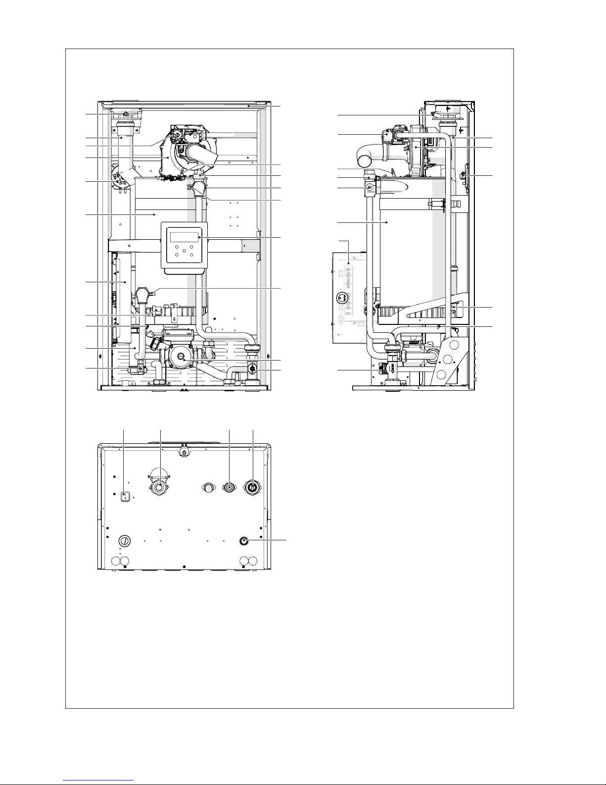
1.6 System layout
POWER MAX
50 P DEP - 50 P
1
3
6
7
17
9
2
5
4
16
13 14 15
1
2
3
4
6
5
7
8
10
9
11
17
18
19
20
12
23
22
24
26
24
21
22
23
25
1
Flue gas analysis outlet
2
Flue gas exhaust connection
3
Gas valve
4
Fan
5
Flue gases pressure switch
6
Combustion chamber
7
Electrical panel
8
Minimum Pressure Switch set at 0,7 bar
9
Exhaust ue probe
10
Condensate drain siphon
11
Drain cock
12
Main switch
13
Central heating return
14
Gas supply
15
Central heating ow
16
Condensate drain connection
17
Flow-meter
18
Pump
19
Return probe
20
Control panel
21
Safety Thermostat with manual reset by PCB
22
Flow probe
23
Automatic bleed valve
24
Ignition/detection electrode
25
Casing
26
Smoke-exhaust ue non-return valve
Page 8

8
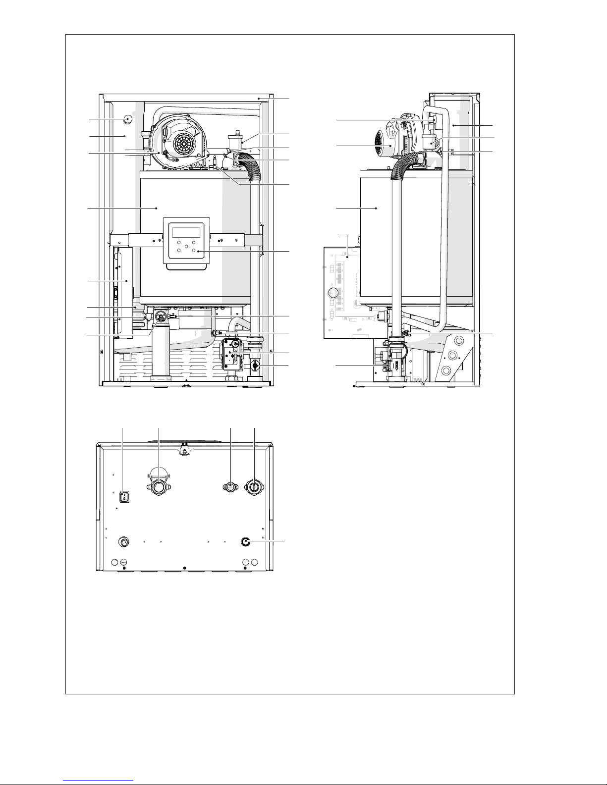
POWER MAX
65 P - 80 P
1
2
3
4
5
1
4
5
6
10
16
6
7
8
9
10
22
20
21
23
24
17
2
21
22
23
3
16
15
1211 13 14
17
19
18
1
Flue gas analysis outlet
2
Flue gas exhaust connection
3
Gas valve
4
Fan
5
Combustion chamber
6
Electrical panel
7
Smoke-exhaust ue non-return valve
8
Drain cock
9
Minimum Pressure Switch set at 0,7 bar
10
Pump
11
Main switch
12
Central heating return
13
Gas supply
14
Central heating ow
15
Condensate drain connection
16
Flow-meter
17
Exhaust ue probe
18
Return probe
19
Control panel
20
Ignition/detection electrode
21
Safety Thermostat with manual reset by PCB
22
Flow probe
23
Automatic bleed valve
24
Casing
Page 9
9
POWER MAX
100 - 110 - 130 - 150
1
3
4
5
14
16
2
21
22
13
109 11 12
1
2
3
4
5
6
7
8
19
23
14
21
20
22
16
15
18
17
1
Flue gas analysis outlet
2
Flue gas exhaust connection
3
Fan
4
Combustion chamber
5
Electrical panel
6
Smoke-exhaust ue non-return valve
7
Drain cock
8
Minimum Pressure Switch set at 0,7 bar
9
Main switch
10
Central heating return
11
Gas supply
12
Central heating ow
13
Condensate drain connection
14
Flow-meter
15
Gas valve
16
Exhaust ue probe
17
Return probe
18
Control panel
19
Ignition/detection electrode
20
Safety Thermostat with manual reset by PCB
21
Flow probe
22
Automatic bleed valve
23
Casing
Page 10
10
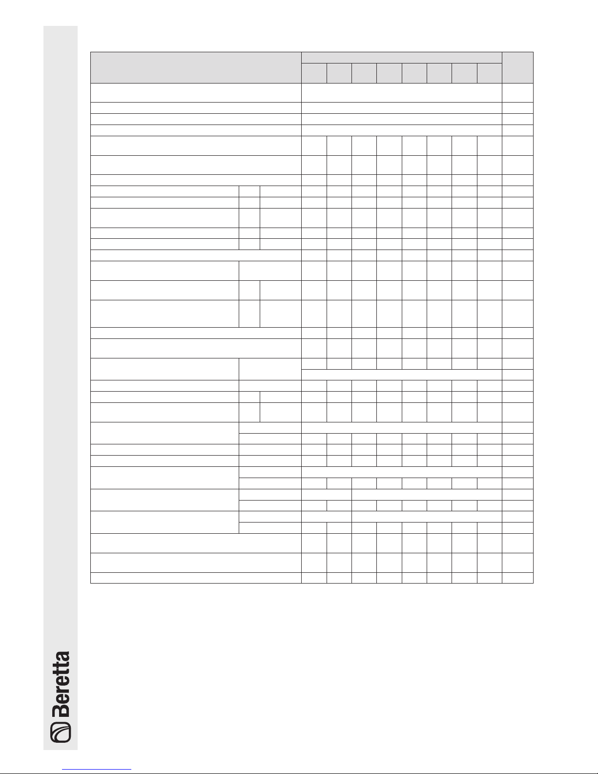
1.7 Technical specications
Description
POWER MAX
U.M.
50 P
DEP
50 P 65 P 80 P 100 110 130 150
Appliance type
Condensing boiler heating system
B23, B53; B53P
Fuel G20-G25-G30-G31
Device category II2H3P
Combustion chamber vertical
Maximum rated heat input at furnace referred to HVC
(LCV)
38,7
(34,9)50(45)63(57)76(68)
100
(90)
108
(97)
124
(112)
146
(131)
kW
Minimum rated heat input at furnace referred to HVC
(LCV)
10
(9)10(9)15(14)15(14)
21,6
(19,4)
21,6
(19,4)
24,9
(22,4)
29,2
(26,2)
kW
Useful (rated) heat output 34,4 44,2 56 68 88 95 110 129 kW
Maximum rated heat output (80-60°C) P4 G20 34,4 44,2 55,7 67,0 88,3 95,3
109,8 129,0
kW
Maximum rated heat output (50-30°C) - G20 38,0 48,8 61,9 73,9 97,4
105,1 121,1 142,1
kW
Maximum nominal heat output (6040°C)
- G20 36,6 47,0 59,6 71,4 93,8
101,1 116,2 137,3
kW
30% heat output with return at 30°C P1 G20 11,5 14,7 18,7 22,3 29,4 31,7 36,6 43,0 kW
Minimum rated heat output (80-60°C) - G20 8,9 8,9 13,5 13,5 19,2 19,2 22,1 26 kW
Efciency class in central heating mode A A A A - - - -
Seasonal energy efciency in central
heating mode
ηs
94 94 94 94 94 94 94 94 %
Efciency at rated heat input and High
temperature GCV (NCV) regime
η4
useful Pn
(60-80°C)
88,5
(98,4)
88,4
(98,3)
88,4
(98,3)
88,2
(97,9)
88,3
(98,0)
88,2
(97,9)
88,6
(98,3)
88,2
(97,9)
%
Efciency at 30% of the nominal thermal ow and on low PCS temperature
regime
η1
useful
30% of
Pn
98,4
(109,5)
98,2
(109,2)
98,2
(109,2)98(108,8)
98,1
(108,9)98(108,8)98(108,8)
98,1
(108,9)
%
Chimney losses with burner on at max. Pn (80-60°C) 2,3 2,3 2,3 2,3 2,5 2,6 2,5 2,6 %
Chimney losses with burner on at max. 30% Pn (50-
30°C)
0,5 0,5 0,5 0,5 0,6 0,6 0,5 0,6 %
Heat loss in standby mode Pstby
45 57 72 87 115 124 143 168 W
0,1 %
Annual energy consumption QHE 71 91 117 141 - - - - GJ
Noise level (sound power)
LWA
at P max 51 52 53 54 55 56 57 57 dB(A)
Emissions (*)
NOx
(referred
to HCV)
42,0 43,9 34,2 36,4 38,1 38,7 39,3 46,1
mg/
kWh
Emissions at max./min. heat input,
G20
CO
2 9 - 9 %
CO
63/2,3 73/2,3 79/6,5 90/6,5 81/7,5
91,5/7,5
89/4,6
91,5/5,6
ppm
Maximum rated heat input (LCV) G25 35 50 53 65 85 93 107 127 kW
Minimum rated heat input (LCV) G25 9 9 13 13 18,1 18,5 21,4 24,5 kW
Emissions at max./min. heat input,
G25
CO
2 9 - 9 %
CO
72/3,2 80/3,2
92/7
93,5/7
84/8 94/8 92/6 95/7 ppm
Emissions at max./min. power G30
CO
2 10,4-9,9 10,4-10,4 %
CO
132/6 137/6
138/10 142/10 148/11 159/11 172/13 180/15
ppm
Emissions at max./min. power G31
CO
2 10,4-9,9 10,4-10,4 %
CO
136/8 141/8
142/11 147/11 153/12 163/12 177/14 185/16
ppm
Flue gas temperature at max. power and min. power
80-60°C
66,5/61 67,5/61
71/61 72/61 76/62 78/62 75/61 77/61
°C
Flue gas temperature at max. power and min. power
50-30°C
44/32 45/32 45/33 46/33 47/35 49/35 45/33 48/35
°C
Flue gas mass ow rate (**)
0,015
0,02
0,025
0,03 0,04
0,046
0,05 0,06 Kg/s
(*)
Weights calculated according to EN 15502.
(**)
Values referred to atmospheric pressure at sea level.
Page 11

11
Description
POWER MAX
U.M.
50 P
DEP
50 P 65 P 80 P 100 110 130 150
Water-side resistance (∆T 20°C)
- - - - 160 210 350 510 mbar
Available useful discharge head (∆T 20°C)
420 250 490 390 - - - - mbar
Maximum working pressure 6 bar
Minimum supply pressure 0,7 bar
Maximum permitted temperature 100 °C
Lockout thermostat activation temperature 95 °C
Adjustment temperature (min / max) 30 / 80 (***) °C
Thermal module water content 5 5 15 15 17 17 23 25 l
Maximum condensation at 100% rated heat output
(50-30°C)
5,4 7,0 8,9 10,1 13,6 15,0 17,5 19,8 l/h
Power supply 230-50 V-Hz
Index of protection IPX4D IP
Consumption at full load Elmax 75 105 63 77 150 203 205 302 W
Consumption at part load Elmin 31 34 30 30 36 31 44 45 W
Electrical consumption in standby
mode
Psb 9 9 13 13 6 6 6 8 W
(***)
Up to 85°C if combined with the plate heat exchanger accessory.
1.8 Pumps
The thermal modulesPOWER MAX 50 P DEP, POWER MAX
50 P, POWER MAX 65 P and POWER MAX 80 P are tted
with a circulator.
Residual head (mbar)
0
100
200
300
400
500
600
700
800
900
0 1,5 2 2,5 3 3,510,5 4
POWER MAX 65 P
POWER MAX 80 P
POWER MAX 50 P DEP
POWER MAX 50 P
Flow-rate (m3/h)
b
At the rst start-up, and at least once a year, the rotation of the circulator shaft should be checked as, especially after long periods of not being operated, deposits and/or residuals could impede its free rotation.
b
Before loosening or removing the circulator cap, protect the electric devices located underneath from any
water that exits.
a
It is prohibited to operate the circulators without water.
Thermal modules POWER MAX 100, POWER MAX 110,
POWER MAX 130 and POWER MAX 150 are not equipped
with a circulator, which must be inside or outside the appliance (see accessories).
For its sizing, consider the thermal module's water-side
pressure drops, which are shown in the chart below.
Water-side pressure drop
Pressure drop (mbar)
0
100
200
300
400
500
600
700
800
900
1000
0 3 4 5 6 7 8 921
POWER MAX 110
POWER MAX 100
POWER MAX 130
POWER MAX 150
Flow-rate (m3/h)
Page 12

12
1.9 Water circuit
2
9
MIRI
1 6 7 8
3
4
5
1
Heat exchanger
2
Circulator (only for models POWER MAX 50 P
DEP - POWER MAX 80 P)
3
Drain cock
4
Minimum pressure switch
5
NTC return probe
6
NTC delivery probe
7
Safety thermostat temperature sensor
8
Automatic bleed valve
9
Flow-meter
MI
Central heating ow
RI
Central heating return
Values of NTC probes' resistors with changing temperatures.
Temperature
°C
Tolerance test
±10%
Resistor
Ω
Temperature
°C
Tolerance test
±10%
Resistor
Ω
-40 191908 45 4904
-35 146593 50 4151
-30 112877 55 3529
-25 87588 60 3012
-20 68471 65 2582
-15 53910 70 2221
-10 42739 75 1918
-5 34109 80 1663
0 27396 85 1446
5 22140 90 1262
10 17999 95 1105
15 14716 100 970
20 12099 105 855
25 10000 110 755
30 8308 115 669
35 6936 120 594
40 5819 125 529
1.10 Positioning the temperature
sensors
Probes placed on the related sockets of the thermal
module (POWER MAX 50 P DEP - POWER MAX 50 P):
1
Exhaust ue probe
2
Safety thermostat temperature sensor
3
CH ow temperature sensor
4
Return probe
1
4
1
3
2
Front view Side view
Probes placed on the related sockets of the thermal
module (POWER MAX 65 P ÷ POWER MAX 150):
1
Exhaust ue probe
2
Safety thermostat temperature sensor
3
CH ow temperature sensor
4
Return probe
3
2
2
3
1
1
4
Front view Side view
Page 13

13
1.11 Control panel
CONTROL PANEL AND SYMBOLS
PROG
RESET
MENU
1
2
4
3
3
1
Rear light display
2
MENU/Reset key: access to the main menu and restore functioning further to a failure lock-out
3
Navigation keys
4
Main switch (located on the lower part of the appliance)
SECONDARY INFORMATION/DISPLAY VISUALISATION
8.8:8.8
8.8:8.8
OUTSIDE
°C
°F
BAR
PSI
1 2 3 4 5 6
89
7
10
1
Icon displayed when heating mode is enabled. Blinking when there is a heat demand
2
Icon displayed when DHW mode is enabled. Blinking when there is an DHW Demand
3
Icon displayed when entering the "Installer" or "Manufacturer" menu
4
Icon displayed when the appliance burner is on
5
Icon displayed when a Permanent or Temporary error occurs
6
Icon displayed when the climatic mode is on (Par. 2001= 1 o 2)
7
Celsius/Fahrenheit temperature
8
Large numeric display: current value
9
Small numeric display: system pressure display or parameter number
10
Icon displayed when the outdoor probe is connected
Page 14
14
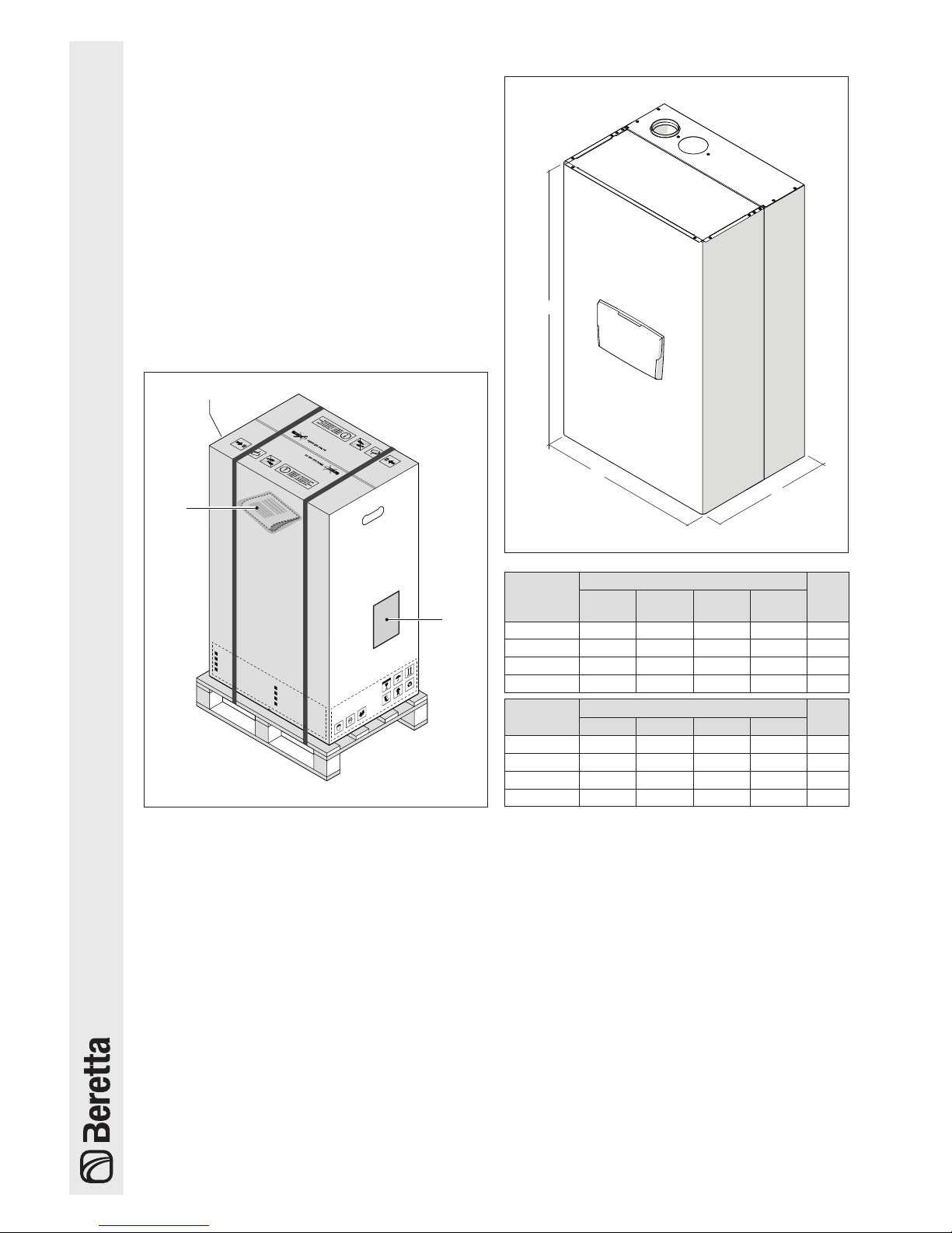
2 INSTALLATION
2.1 Unpacking the product
The thermal module
POWER MAX
is shipped palletised,
packaged and with cardboard protections.
The following material is supplied in a plastic envelope inside the package (1):
- Instruction manual
- Warranty information leaet B
- LPG conversion kit
- Wall-mounting bracket with plugs (no.4 plugs s=10
mm suitable for concrete, brick, compact stone and
concrete hollow brick walls)
- Hydraulic test certicate
- Energy Efciency Label (for models <70kW)
2.1.1 Positioning of labels
A
A
CALDAIA MURALE A GAS
WALL HUNG GAS BOILER
CHAUDIERE MURALE A GAZ
GAS - WANDHEIZKESSEL
IT
GB
FR
D
CALDAIA MURALE A GAS
WALL HUNG GAS BOILER
CHAUDIERE MURALE A GAZ
GAS - WANDHEIZKESSEL
IT
GB
FR
D
1
A
Packing label
b
The instruction manual is an integral part of the appliance; therefore, it should be read and stored carefully.
b
Keep the documentation envelope in a safe place.
Any replacement documents must be ordered from
Beretta who reserve the right to charge for the cost of
the replacement.
2.2 Overall dimensions and weights
P
H
L
Description
POWER MAX
50 P
DEP
50 P 65 P 80 P
L 600 600 600 600 mm
P 435 435 435 435 mm
H 1000 1000 1000 1000 mm
Net weight 65 65 70 64 kg
Description
POWER MAX
100 110 130 150
L 600 600 600 600 mm
P 435 435 435 435 mm
H 1000 1000 1165 1165 mm
Net weight 78 78 90 95 kg
Page 15

15
2.3 Installation premises
The thermal module
POWER MAX
can be installed in rooms
that are permanently ventilated and equipped with suitably
sized ventilation openings in line with Technical Standards
and Regulations applicable to the installation site.
b
When installing the boiler, allow sufcient space
around it to access all safety and control devices and
to permit easy maintenance.
b
Check that the electric protection level of the appliance is suitable for features of the room where it is
installed.
b
Make sure that comburent air is not contaminated by
substances containing chlorine or uorine (elements
found in sprays, paints, detergents etc.).
a
Do not obstruct or restrict the air vents in the room
where the boiler is installed. A free air supply is essential for correct combustion.
a
It is forbidden to leave ammable containers and
substances in the room where the thermal module is
installed.
2.3.1 Recommended minimum distances
Clearances for the assembly and the maintenance of the
appliance are shown in the gure.
≥ 1 m
≥ 0,85 m
≥ 0,4 m
≥ 0,5 m
≥ 0,5 m
The minimum surface of ventilation openings is 3,000 cm2
for gas fuel heating systems.
2.4 Installation in older systems and
systems requiring modernisation
When installing these boilers in older systems or systems
requiring modernisation, always perform the following
checks:
- Make sure that the ue is able to withstand the temperature of the combustion gases and that it has been
designed and made in compliance with applicable
standards. The ue must also be as straight as possible, sealed, insulated and not blocked or choked.
See Paragraph "Discharge of combustion products"
for any additional information.
- Make sure that the electrical supply system has been
installed by a qualied electrician in compliance with
applicable standards
- Make sure that the fuel feed line and any storage tank
are made and installed in compliance with applicable
standards
- Make sure that expansion vessels are big enough to
contain the additional volume generated by thermal
expansion
- Make sure that the ow rate, head and direction of
ow of the pumps are suitable and correct
- The system has been washed, cleaned of mud and
grime and water seals have been checked
- A treatment system is tted when the supply/rell
water has values other than those indicated in Paragraph "Water quality requirements"
b
The manufacturer declines all responsibility for dam-
age caused by incorrectly constructed ue systems.
Page 16
16
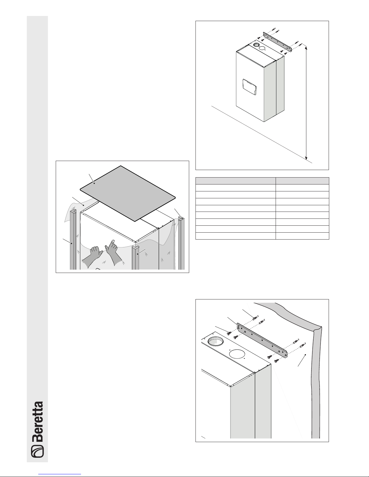
2.5 Moving and removing the
packing
b
Do not remove the cardboard packaging until your
reach the installation location.
b
Before handling the appliance and removing the
packaging, wear PPE and use tools suitable for the
appliance's size and weight.
b
This step must be carried out by several individuals
equipped with suitable means with respect to the appliance's size. Make sure that the load is not unbalanced during handling.
Proceed as follows to remove the packing:
- Remove the strapping that secures the cardboard
packaging to the pallet
- Remove the cardboard
- Remove edge protectors (1)
- Remove the Styrofoam protection (2)
- Remove the protective bag (3)
3
1
2
1
1
2.6 Thermal module assembly
Thermal modules
POWER MAX
are supplied complete with
a wall-mounting bracket.
b
Check that the wall on which the appliance is to be
tted is sufciently solid and supports safe screw xing points.
b
The appliance's height must be selected so as to facilitate dismantling it and maintaining it.
H
Model Height (H) mm
POWER MAX 50 P DEP 1850<H<2000
POWER MAX 50 P 1850<H<2000
POWER MAX 65 P 1850<H<2000
POWER MAX 80 P 1850<H<2000
POWER MAX 100 1850<H<2000
POWER MAX 110 1850<H<2000
POWER MAX 130 2000<H<2150
POWER MAX 150 2000<H<2150
For installation:
- Position the bracket (1) onto the wall (2), at the point
where you wish to install the appliance
- Ensure that the bracket is horizontal and mark the
points where the holes for xing plugs must be drilled
- Drill the holes and insert expansion plugs (3)
- Fix the bracket to the wall using the screws (4)
- Secure the appliance onto the bracket
1
2
3
4
Page 17
17
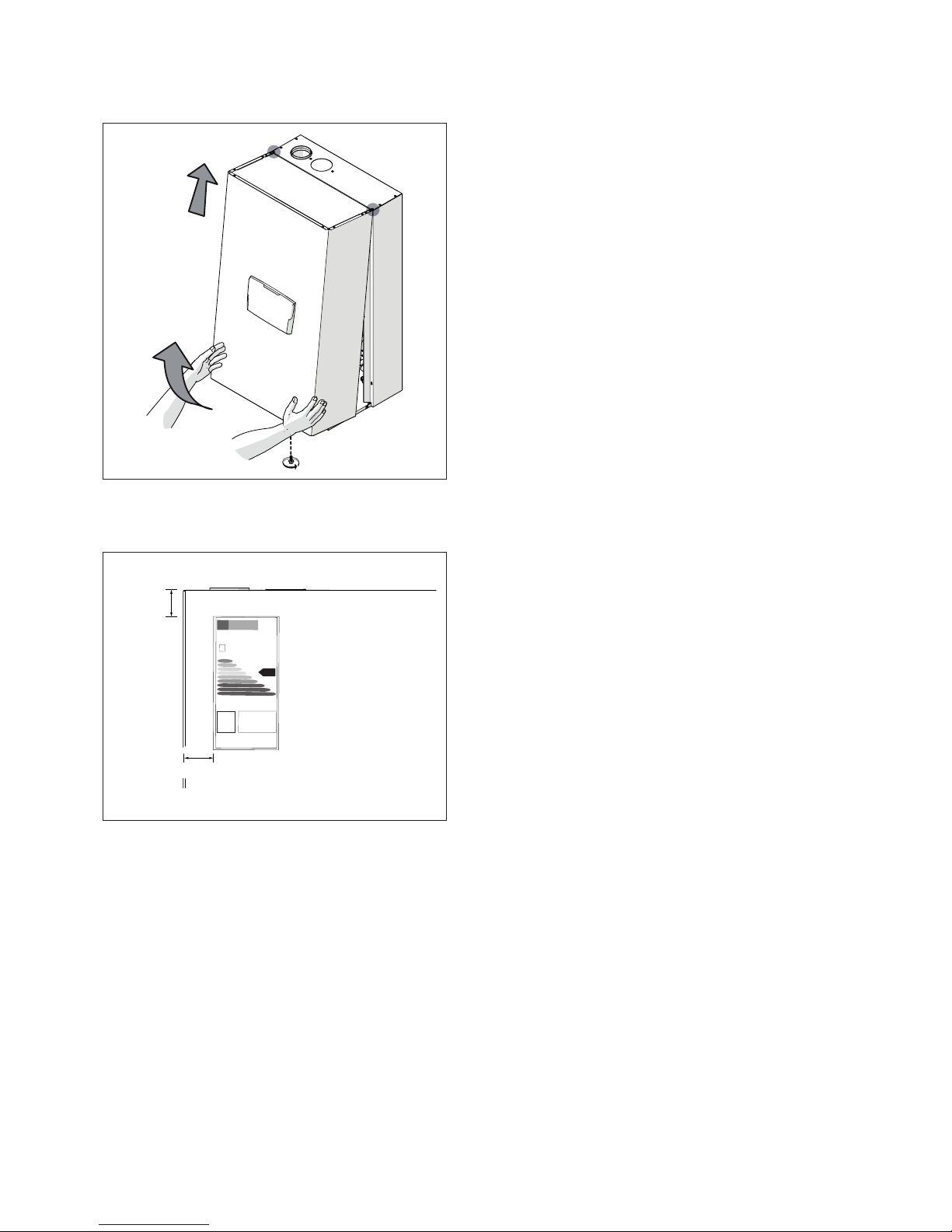
After installing the thermal module:
- remove the locking screw
- pull the front panel outwards and then to the top to
decouple it from points A.
A
A
Locate the envelope containing the product documentation
and stick the Energy Efciency Label (if any) contained in
the envelope onto the panel.
25 kW
30 mm
25 mm
Close the panelling in reverse order to the one described
above.
b
Before proceeding with the hydraulic connections the
protection plugs must be removed from the delivery,
return and condensate drain piping.
Page 18
18
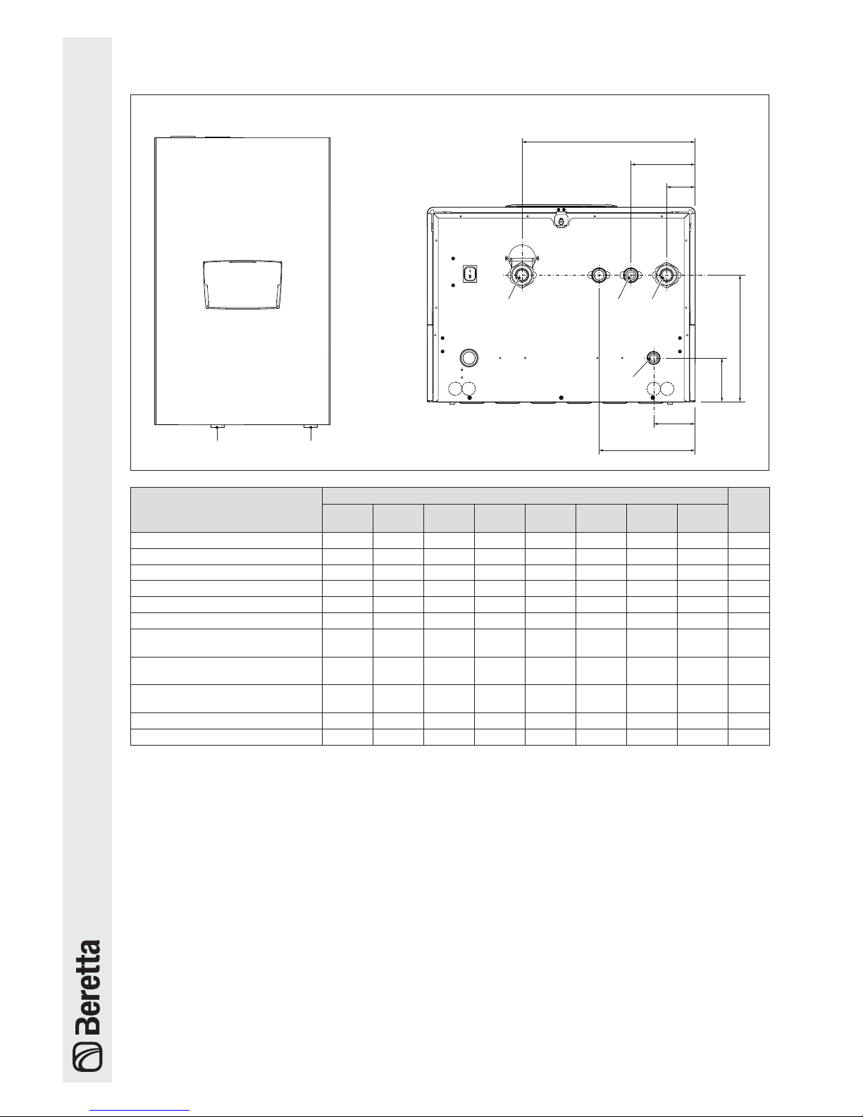
2.7 Water connections
The dimensions and position of thermal module's hydraulic connections are shown in the table below.
Front view Bottom view
RI MI
B
A
F
H
C
D
E
RI G MI
SC
DESCRIPTION
POWER MAX
50 P
DEP
50 P 65 P 80 P 100 110 130 150
A 387 387 387 387 387 387 387 387 mm
B 143,5 143,5 143,5 143,5 143,5 143,5 143,5 143,5 mm
C 63,5 63,5 63,5 63,5 63,5 63,5 63,5 63,5 mm
D 283,5 283,5 283,5 283,5 283,5 283,5 283,5 283,5 mm
E 98,5 98,5 98,5 98,5 98,5 98,5 98,5 98,5 mm
F 92,5 92,5 92,5 92,5 92,5 92,5 92,5 92,5 mm
H (optional 3-way valve
attachment)
202,5 202,5 - - - - - - mm
MI (system ow)
G 1" 1/2 MG 1" 1/2 MG 1" 1/2 MG 1" 1/2 MG 1" 1/2 MG 1" 1/2 MG 1" 1/2 MG 1" 1/2
M
Ø
RI (system return)
G 1" 1/2 MG 1" 1/2 MG 1" 1/2 MG 1" 1/2 MG 1" 1/2 MG 1" 1/2 MG 1" 1/2 MG 1" 1/2
M
Ø
SC (condensate drain) 25 25 25 25 25 25 25 25 Ø mm
G (gas inlet) G 1" M G 1" M G 1" M G 1" M G 1" M G 1" M G 1" M G 1" M Ø
b
Before connecting the thermal module the protection
plugs must be removed from the delivery, return and
condensate drain pipes.
b
Before connecting the thermal module, it is necessary to clean the system. This step is absolutely required when the appliance replaces another one on
pre-existing systems.
In order to carry out this cleaning activity, if the old generator is still installed on the system, it is advisable to:
- add a de-scaling additive.
- Operate the system with the generator on for around
7 days.
- Discharge dirty system water and ush the system
one or more times with clean water.
If the system is very dirty, repeat the last procedure one
more time.
If the old generator is not present or available, use a pump
to circulate the water + additive through the system for
about 10 days and perform a nal washing as described in
the previous paragraph.
Once the cleaning has been completed, it is recommend-
ed to add a suitable protective uid to the system's water
before installing the thermal module.
In order to clean the heat exchanger's built-in water system, please contact Technical Assistance Centre
B.
a
Do not use incompatible liquid detergents, including
acids (for instance, chloridric acid and similar) in any
concentration.
a
Do not subject the heat exchanger to cyclical pressure changes because fatigue stress is very dangerous for the integrity of system components.
Page 19

19
2.8 Typical water system schematics
Layout 1: circuit with thermal module directly linked to heating system (check that the pump's discharge head
is sufcient to ensure adequate circulation)
10 9
EAF
MI
2
1
RI
1
11
14
4
5
6
7
8
SE
Layout 2: circuit with thermal module directly linked to heating system and DHW tank. (check that the pump's
discharge head is sufcient to ensure adequate circulation)
5
UAC
1
9
10
1
EAF
6
13
12
1
1
2
3
4
11
10 9
EAF
MI
2
1
RI
1
11
5
6
7
8
SE
6
14
4
1
Isolating valve
2
Non-return valve
3
DHW circulation pump
4
Expansion tank
5
Safety valve
6
Drain
7
Pressure gauge
8
Pressure switch
9
Water softener lter
10
Pressure reducer
11
Storage cylinder
12
Automatic bleed valve
13
Diverter valve
14
Pump (tted as standard for models POWER MAX 50 P DEP and
POWER MAX 80 P)
15
High-temperature system circulator
16
Storage cylinder circulator
SE
Outdoor sensor
MI
High temperature
system ow
RI
High temperature
system return
EAF
Domestic cold wa-
ter inlet
UAC
Domestic hot water
outlet
b
Domestic hot water and central heating circuits must be completed with expansion vessels of adequate capacity
and suitable, correctly-sized safety valves. The discharge of safety valves and appliances must be connected to a
suitable collection and disposal system (see Catalogue for compatible accessories).
b
The choice of system components and the method of their installation are left up to the heating engineer installing
the system. Installers must use their expertise to ensure proper installation and functioning in conformity to all applicable legislation.
b
Special supply/rell water must be conditioned using suitable treatment systems.
a
It is prohibited to operate the thermal module without water.
Page 20

20
Layout 3: circuit with thermal module connected to a heating system via a separator
10 9
EAF
MI
2
11
RI
1
11
15
5
6
7
8
SE
14
4
Layout 4: circuit with thermal module linked to DHW tank and heating system via a separator
15
5
UAC
1
9
10
1
EAF
6
12
1
1
2
3
4
11
10 9
EAF
MI
2
11
RI
1
11
5
6
7
8
SE
6
16
14
4
1
Isolating valve
2
Non-return valve
3
DHW circulation pump
4
Expansion tank
5
Safety valve
6
Drain
7
Pressure gauge
8
Pressure switch
9
Water softener lter
10
Pressure reducer
11
Storage cylinder
12
Automatic bleed valve
13
Diverter valve
14
Pump (tted as standard for models POWER MAX 50 P DEP and
POWER MAX 80 P)
15
High-temperature system circulator
16
Storage cylinder circulator
SE
Outdoor sensor
MI
High temperature
system ow
RI
High temperature
system return
EAF
Domestic cold wa-
ter inlet
UAC
Domestic hot water
outlet
b
Domestic hot water and central heating circuits must be completed with expansion vessels of adequate capacity
and suitable, correctly-sized safety valves. The discharge of safety valves and appliances must be connected to a
suitable collection and disposal system (see Catalogue for compatible accessories).
b
The choice of system components and the method of their installation are left up to the heating engineer installing
the system. Installers must use their expertise to ensure proper installation and functioning in conformity to all applicable legislation.
b
Special supply/rell water must be conditioned using suitable treatment systems.
a
It is prohibited to operate the thermal module without water.
Page 21

21
Layout 5: circuit with thermal module linked to heating system and DHW. tank via a separator
15
5
UAC
1
9
10
1
EAF
6
12
1
1
2
3
4
11
10 9
EAF
MI
2
11
RI
1
11
5
6
7
8
SE
6
13
14
4
1
Isolating valve
2
Non-return valve
3
DHW circulation pump
4
Expansion tank
5
Safety valve
6
Drain
7
Pressure gauge
8
Pressure switch
9
Water softener lter
10
Pressure reducer
11
Storage cylinder
12
Automatic bleed valve
13
Diverter valve
14
Pump (tted as standard for models POWER MAX 50 P DEP and
POWER MAX 80 P)
15
High-temperature system circulator
16
Storage cylinder circulator
SE
Outdoor sensor
MI
High temperature
system ow
RI
High temperature
system return
EAF
Domestic cold wa-
ter inlet
UAC
Domestic hot water
outlet
b
Domestic hot water and central heating circuits must be completed with expansion vessels of adequate capacity
and suitable, correctly-sized safety valves. The discharge of safety valves and appliances must be connected to a
suitable collection and disposal system (see Catalogue for compatible accessories).
b
The choice of system components and the method of their installation are left up to the heating engineer installing
the system. Installers must use their expertise to ensure proper installation and functioning in conformity to all applicable legislation.
b
Special supply/rell water must be conditioned using suitable treatment systems.
a
It is prohibited to operate the thermal module without water.
Page 22

22
2.9 Gas connections
The gas connection must be made respecting the installation regulations in force, and sized to ensure the correct
gas delivery to the burner.
Before making the connection, check that:
b
The gas type is suitable for the appliance
b
If the appliance needs to be adapted for use with
another gas fuel, contact your local Technical As-
sistance Centre to have the necessary modications
made. These operations may not be performed by
the installer under any circumstances.
b
The piping is thoroughly clean
b
The gas meter's ow rate is capable of ensuring the
simultaneous use of all the appliances connected to
it. The appliance's connection to the gas supply line
must be carried out in accordance with the current
regulations.
b
Intake pressure with the appliance in the off position
has the following reference values:
- powered by methane gas: optimal pressure 20
mbar
- powered by L.P.G.: optimal pressure 35 mbar
b
Check that the pressure never falls below 15 mbar
a
Do not use any fuels other than those provided under
any circumstances.
While it is normal for the intake pressure to decrease while
the appliance is in operation, it is advisable to verify that
no excessive pressure uctuations take place. In order to
limit the extent of these types of variations, the diameter of
the gas supply line to be used must be assessed based on
the length and the pressure drops of the line itself, from the
meter to the thermal module.
b
If uctuations in the gas distribution pressure are encountered, it is recommended to install an appropriate pressure stabiliser upstream of the appliance's
gas intake. For G30 and G31 gas supply, all the necessary precautions must be taken in order to prevent
the gas from freezing in the case of extremely low
outdoor temperatures.
If the gas distribution network contains solid particles, in-
stall a lter on the fuel supply line. When selecting it, consider that pressure drops due to the lter should be as low
as possible.
b
On completion of the installation, check that all joints
are sealed.
GAS 1" M
2.10 Discharge of combustion
products
The appliance is supplied as standard in B-type conguration (B23-B23P-B53P), i.e. pre-tted to suction air direct-
ly into the installation room and may be converted into a
C-type appliance with the use of specic accessories. In
this conguration, the appliance will suction the air directly
from outdoors, with the possibility of coaxial or dual piping.
For ue gas extraction and the intake of combustion air, it is
essential to use only specic pipes for condensing boilers
and ensure that they are correctly connected, as shown
in the instructions supplied with the ue gas accessories.
b
Do not connect this appliance's ue gas extraction pipes with those of other appliances, unless
this is specically authorised by the manufacturer.
Non-compliance with this precaution may cause a
build-up of carbon monoxide in the room where the
appliance is installed. This could jeopardise people's
health and safety.
b
For further information on ue gas extraction pipes for
thermal modules connected in a cascaded system,
see Catalogue and the instructions provided for the
relevant accessories.
b
Ensure that combustion air (suction line air) is not
contaminated by:
- waxes/chlorinated detergents
- chemical products based on swimming pool chlorine
- calcium chloride
- sodium chloride use to soften tap water
- refrigerant leaks
- paint or varnish removers
- chloridric acid/muriatic acid
- cements and glues
- anti-static softeners used in dryers
- chloride used for domestic or industrial applications
as detergent, whitener or solvent
- adhesives used to glue construction and other similar products.
b
To prevent contamination of the thermal module, do
not install suction line air intakes and gas ue extraction pipes near:
- dry-cleaners/laundry rooms and factories
- swimming pools
- metal processing plants
- beauty parlours
- fridge repair shops
- photo-processing facilities
- body-shops
- plastics manufacturing plants
- furniture workshops and manufacturing plants.
Page 23

23
UF AA
326
96
92
230
The AA outlet is supplied capped in B23 conguration.
DESCRIPTION
POWER MAX
50 P
DEP
50 P 65 P 80 P
FO (ue gas outlet) DN80 DN80 DN80 DN80 Ø
AS (air suction) DN80 DN80 DN80 DN80 Ø
DESCRIPTION
POWER MAX
100 110 130 150
FO (ue gas outlet)
DN110 DN110 DN110 DN110
Ø
AS (air suction)
DN110 DN110 DN110 DN110
Ø
b
For B-type installation, combustion air is taken from
the environment and goes through the openings
(shutters) on the rear panel of the device that must be
located in a suitable and ventilated technical room.
b
Read the requirements, instructions and prohibitions
detailed below carefully, since non-compliance with
them may be result in a safety hazard or the appliance's malfunction.
b
Condensation appliances described in this hand-
book must be installed with ue gas pipes compliant
with applicable legislation and expressly manufac-
tured for this specic use.
b
Check that pipes and joints are not damaged.
b
Joint seals must be executed with materials that withstand the condensate's acidity and the temperatures
of the appliance's ue gases.
b
When installing ue pipes, always bear in mind the
direction of the ue gases and of possible condensate ows.
b
Inadequate or incorrectly sized ue gas pipes may
increase combustion noise, create condensate extraction issues and negatively impact on combustion
parameters.
b
Check that pipes are suitably far (min. 500 mm) from
ammable or heat-sensitive construction elements.
b
Make sure that condensation is not built up along the
duct. For this purpose, provide a sloping duct of at
least 3 degrees towards the appliance in case there
is an a horizontal section. If the horizontal or vertical
section is longer than 4 meters, a condensate siphon
drainage must be provided at the base of the pipe.
The useful height of the siphon must be at least equal
to the value "H" (see gure below). The siphon discharge must then be connected to the sewerage system (see paragraph "Preparation for the condensate
drain" on page 24).
a
It is prohibited to block or section the ue gas extraction pipe or the combustion air suction pipe, if any.
a
It is prohibited to use pipes that not designed for this
application, because the condensate's action would
damage them quickly.
Maximum equivalent lengths are provided below.
Maximum equivalent length
of ue gas exhaust pipe
Pressure drop
45° bend 90° bend
30 m 1 m 3 m
The table with available residual discharge heads is shown
below.
Description
Discharge head
Max Min
POWER MAX 50 P DEP 300 45
POWER MAX 50 P 480 45
POWER MAX 65 P 510 35
POWER MAX 80 P 630 35
POWER MAX 100 560 32
POWER MAX 110 610 32
POWER MAX 130 500 30
POWER MAX 150 353 28
The residual discharge head values are shown in Pascal.
≥3°
H 350 mm
To change direction, use a T section with an inspection
cap to permit easy access for cleaning inside the pipe. After cleaning, always make sure that inspection caps are
replaced tightly and that their seals are undamaged and
efcient.
Page 24

24
2.10.1 Preparation for the condensate drain
The exhaust of the condensation produced by the appliance
POWER MAX
during its normal operation, must be carried out with an accessory (siphoned condensate collector)
that needs to be installed below the thermal module itself
as specied in its assembly instructions. The condensate
coming out of the drainer must be collected for dripping
into a taped vessel connected to the sewer system, if necessary by interposing a neutralizer (for more information
see paragraph "Neutralising the condensate"), according
to the following procedure:
- Fit a drip tray near the condensate discharge outlet,
adding a condensate neutraliser if necessary
- Connect the drip collection receptacle to the local
drain or sewer system using a siphon.
The drip tray can be created by tting a cup or simply a
polypropylene bend, suitable for collecting the condensate
that comes out of the appliance and any liquid leaking from
the safety valve.
The maximum distance between the condensate drainage
of the appliance and the socket (or socket pipe) must not
be less than 10 mm.
The connection to the local drain or sewer system must be
executed using a siphon in order to prevent unpleasant
odours from being released back into the room from the
sewer.
We advise using plastic (PP) piping for building the condensate drainage.
a
Never use copper pipes under any circumstances,
as the condensate itself will cause them to rapidly
deteriorate.
H
Drip tray
Condensate
basing
(accessory)
i >3%
residential discharge
b
Execute the condensate drain outlet so as to prevent
combustion gases leaking into the environment or the
drain or sewage system by sizing the siphon (height
H) as described in Paragraph "Discharge of combustion products".
b
Always maintain a slope angle “s” of over 3° and ensure that the diameter of any condensate drain pipe
is greater than that of the connection tted at the
drain outlet
b
Connect the condensate drain hose to a domestic
water drain in accordance with national and local
legislation and standards.
b
Fill the siphon with water before activating on the
thermal module in order not to release any combustion products into the environment when the thermal
module is rst switched on.
b
The condensate drain must be suitably siphoned. Fill
the siphon with drain in order to prevent the release
of combustion products when the appliance is rst
switched on.
b
It is recommended that condensate from the thermal
module and from the ue should be channelled to the
same drain pipe.
b
The connection pipes used must be as short and as
straight as possible. Any curves or sharp bends can
lead to hoses becoming clogged and, therefore, can
prevent proper condensate discharge
b
Size the condensate drain outlet so as to ensure the
proper drainage of waste liquids without leaks
b
The condensate drain must be connected to the
drain and sewage network in such a ways so that the
condensate may not freeze under any circumstances
2.11 Neutralising the condensate
The UNI 11528 Standard provides for mandatory neutralisation of condensate for systems with total power of over
200 kW. For systems with total power from 35 to 200 kW,
neutralisation may or may not be mandatory depending on
the number of ats (for residential applications) or the number of occupants (for non-residential applications) served
by the aforementioned system.
2.11.1 Water quality requirements
It is ABSOLUTELY NECESSARY to treat the water system in
order for the heat generator to work properly and to guarantee its service life, as well as that of all its components.
This not only applies to jobs carried out on existing installations but also on new installations.
Sludge, lime-scale and pollutants contained in the water
can cause permanent damage to the heat generator, also
within a short time and notwithstanding the quality standards of the materials used.
Contact the Technical Assistance Centre for any further information on type and use of additives.
The heat transfer uid (water) for the central heating circuit
must conform to the quality parameters given in the following table:
Page 25

25
Parameters Value Unit
General characteristic
Colourless, without
sediment
PH value Min. 6.5; Max. 8 PH
Dissolved oxygen < 0,05 mg/l
Total iron (Fe) < 0,3 mg/l
Total copper (Cu) < 0,1 mg/l
Na2SO3 < 10 mg/l
N2H4 < 3 mg/l
PO4 < 15 mg/l
CaCO3 Min. 50 ; Max.150 ppm
Trisodium phosphate None ppm
Chlorine < 100 ppm
Electrical conductivity <200
micro-
siemens/
cm
Pressure Min. 0.6; Max. 6 bar
Glycol
Max. 40% (only pro-
pylene glycol)
%
b
All data in the table refer to water contained in the
system after 8 weeks' operation.
b
Do not use excessively softened water. Excessive
water softening (total hardness < 5° f) results in corrosion due to contact with metal elements (pipes or
thermal module components)
b
Immediately repair any leaks or drips that could result
in air entering the system
b
Excessive pressure uctuations can cause stress
and fatigue to the heat exchanger. Keep the operating pressure constant.
b
Water used to ll a system for the rst time and water
used to top it up must always be ltered (using synthetic or metal mesh lters with a ltration rating of no
less than 50 microns) to prevent sludge from forming
and triggering deposit corrosion.
b
If oxygen enters a circuit continuously or even inter-
mittently (e.g. in under-oor heating systems whose
pipes are not protected by impermeable synthetic
sheaths, in circuits with open expansion vessels, or
in circuits that require frequent top-ups) always separate the boiler’s water circuit from the central heating
circuit.
a
It is prohibited to top up the heating system constantly or frequently, since this can damage the thermal
module's heat exchanger. The use of automatic topping up systems should be avoided for this reason.
To sum up, in order to eliminate contact between air and
water (and to prevent the latter from becoming oxidized),
it is necessary:
- that the expansion system be a closed vessel, correctly sized and with the correct pre-loading pressure
(to be regularly checked);
- that the system be always at a pressure higher than
the atmospheric one at any point (including the pump
suction side) and under any operating conditions (all
seals and hydraulic couplings in a system are designed to withstand pressure towards the outside,
but not underpressure);
- the installation be not made with gas-permeable materials (e.g. plastic pipes without oxygen barrier for
underoor heating systems)
b
Damages suffered by the thermal module, caused
by encrustations and corrosion, are not covered by
warranty. In addition, the non compliance of the water
requirements listed in this chapter will void the appliance warranty itself.
2.12 System lling and emptying
The thermal module
POWER MAX
must be provided with a
charging system to be connected to the appliance's return
line.
RI
Before lling or emptying the system, switch the system's
master switch to the OFF position and the thermal module's
master switch to (
0
).
2.12.1 Filling
- Make sure that drain cocks (1) are closed before you
start loading the system
POWER MAX 50 P DEP - POWER MAX 50 P
1
Page 26

26
POWER MAX 65 P ÷ POWER MAX 150
1
- Unscrew the vent valve's release cap
- Open the shut-off cocks in order to slowly ll the system
- Use the pressure gauge to check that the pressure is
rising and the water is exiting through the vent valves
- Close the shut-off cocks after the pressure reaches
1.5 bar
- Start the system pumps and the thermal module's
pump as shown in Paragraph "Commissioning and
maintenance"
- During this stage, check that the air is correctly eliminated
- Restore the pressure if necessary
- Switch the pumps off and on again
- Repeat the last three steps until the pressure is stabilised
b
The system must be lled up slowly the rst time;
once it is lled and the air expelled it should never
need to be topped up again.
b
Systems should also be operated at maximum work-
ing temperature the rst time they are started up, in
order to facilitate de-aeration. (Gas is not released
from the water at low temperatures).
b
An automatic spurge can be performed during the
rst ignition. The parameter that set the cycle is Par.
2139. See parameter table for more information.
2.12.2 Emptying
Before starting to empty the appliance and the storage cylinder:
- Switch the system's master switch to the OFF position
and the thermal module's master switch to (0).
- Close the water supply shut-off cocks;
- In order to empty the appliance, t a rubber hose (2)
(inner diameter int. Ø = 12 mm) to the thermal module's discharge valve (1).
POWER MAX 50 P DEP - POWER MAX 50 P
1
2
POWER MAX 65 P ÷ POWER MAX 150
1
2
Page 27

27
2.13 Wiring diagram
BUS 2
BOTTOM VIEW
BUS 1 PWMSESB SS24V
MO1
0-10V TA
EA
SF
SR
SM
TS
FL
Pm
SCH
PWM
0V (GND)
PF
J9-1
J9-3
J9-2
J9-4
J6-2
J6-1
J6-8
J6-4
J6-11
J6-6
J6-13
J6-7
J6-14
J7-5
J7-10
J8 J11 J12 J7 J10 J9
J6
J8-1
J8-2
J12-5
J12-2
J7-8
J7-7
J7-6
J12-1
J12-4
J7-4
J7-2
J6-5
J6-12
J6-10
J6-3
b h
h
h
h
h
h
b
b
bl
b
w
r
b
b
b h bl b h b h b h b h b h
b
h
1 2 3 4 9 10 11 12 13 14 15 16 17 185 6 7 8
J7-2 h
J7-3 b
PROG
RESET
MENU
J25-1 g
J25-2 b
J25-3 y
J25-4 w
J25
Key
EA
Ignition/detection electrode
SF
Exhaust ue probe
SM
Flow probe
SR
Return probe
TS
Safety thermostat
PF
Flue gases pressure switch (**)
Pm
Minimum pressure switch
FL
Flow-meter
SCH
Display and control card
MO1
Low-voltage terminal board
0-10V
0-10V input
TA
Room/heat demand thermostat
24 V
24V exit
SB
Boiler sensor (accessory)
SS
System probe (accessory)
SE
Outdoor sensor (accessory)
PWM
PWM connection (*)
Cable colour
b
brown
h
blue
r
red
w
white
bl
black
g
yellow/green
y
yellow
gr
green
(*)
Factory connections for models POWER MAX 50 P DEP ÷ POWER MAX 80 P
(**)
Only for models POWER MAX 50 P DEP ÷ POWER MAX 50 P
Page 28

28
PC (*)
VG1
VE1
IG
MO2
AE (230V ~ 50Hz)PI PC (PS)(ACS) ALPB
PWM
0V (GND)
L
N
L N
L N
L LN
L N
J2J1J3
J4J5
F1
J17
J2-1
J2-4
J1-4
J1-5
J1-1
J4-2
J4-3
J4-6
J4-5
J5-2
J5-1
J3-1
J3-7
J3-2
J3-3
J3-8
J3-5
J3-10
J3-4
J2-3
J3-9
J4-4
J4-1
g
g
g
g
b
h
g
b
h
b
h
gr
w
y
b
b
h
b
b
b
b
g
h
h
h
h
J3-6
b
bl
101 102 103 104 105 106 107 108 109 110 111 11 2 113 114 11 5
L NL N
Key
IG
Main switch
VG1
Gas valve
VE1
Variable speed fan
MO2
High-voltage terminal board
PB
Storage cylinder circu-
lator/ 3-way valve/2-way
valve (**)
PI
Central heating system pump
(ACS)
DHW circulator (**)
PC
Thermal module circulator (*)
PS
System circulator (**)
AL
Alarm output
AE
Power supply
Cable colour
b
brown
h
blue
r
red
w
white
bl
black
g
yellow/
green
y
yellow
gr
green
(*)
For models POWER MAX 50 P DEP ÷ POWER MAX 80 P circulator tted as standard; for other models, the
circulator is provided as an accessory with connections to be executed by the installer.
(**)
Valid conguration for thermal modules without heat pump c having their own two-way valve, connected
in cascade and equipped with primary system circulator. For more information, see cascade installation
manual.
Page 29

29
2.14 Electrical connections
The thermal module
POWER MAX
is manufactured fully
wired and only needs to be connected to the mains, the
room/heat demand thermostat and any other system components.
b
The following is mandatory:
- The use of an omnipolar magnetothermic switch,
line disconnecting switch in compliance with CEI-EN
standards (contact opening of at least 3 mm)
- Respect the connection L (line) - N (neutral). Keep
the earth conductor 2 cm longer than the power supply conductors
- Use cables with a section greater than or equal to 1.5
mm2, complete with cable terminal caps
- Refer to the wiring diagrams in this manual for all
electric operations.
b
The use of adaptors, multiple sockets and extensions
to power the appliance is not allowed
b
to connect external electric components, it is necessary to use auxiliary relays and/or contactors to be
tted in a dedicated external electrical panel
b
Any work on the electrical system must be carried
out only by qualied personnel in compliance with all
legal provision and safety regulations in particular
b
Secure the cables into the dedicated cable ties in
order to always guarantee their correct positioning
within the appliance.
b
Electrical supply cables and control cables (room/
heat demand thermostat, external temperature
probes, etc.) must be strictly separate the one from
the other and tting inside independent ribbed PVC
sheaths up to the electrical panel.
b
The connection to the electrical power supply must
be performed using type 1 sheathed cables (3 x
1,5) N1VVK or equivalent, while simple N07VK type
or equivalent conductors can be used for the thermoregulation and low voltage circuits.
b
If the electrical power provided by the electrical company is of "
PHASE-PHASE
" connection type, preventively contact the nearest Technical Assistance Centre.
b
Never shut the appliance off during normal operation
(with the burner on) by shutting off the electrical power supply using the On-Off key or an external switch.
This could cause the primary heat exchanger to overheat.
b
To switch it off (during the heating stage) use a room/
heat demand thermostat. The On-Off key can only be
actioned whist the appliance is in stand-by or emergency mode.
b
Before connecting any external electrical components to the appliance (regulators, electric valves,
climate control probes, etc.), check to make sure that
their electrical characteristics are compatible with the
available inputs and outputs (voltage, absorption, acceleration current).
b
Temperature probes must be NTC like. For resistance value, refer to table pag 12
b
Always check the proper operation of the "grounding
conductor" for the electrical system to which the appliance will be connected.
b
B shall bear no responsibility for any personal
injuries or property damage caused by non-compliance with wiring diagrams or the electrical system's incorrect/lacking connection to the grounding
system, or by non-compliance with applicable CEI
Standards.
a
It is strictly forbidden to use pipes of any kind to
ground the appliance.
a
It is prohibited to lay power supply and room/heat demand thermostat cables near hot surfaces (delivery
pipes). If they may come into contact with parts that
have a temperature of over 50°C, use a suitable type
of cable.
a
It is prohibited to touch electric appliances with
damp/wet body parts or when your feet are wet.
a
It is prohibited to leave the appliance exposed to
weather elements (rain, sun, wind, etc.) unless it is
equipped with the relevant weatherproof kit.
a
It is prohibited to pull, detach, or twist any electric cables coming from the thermal module even when the
latter is disconnected from the mains power supply.
Proceed as follows to access the control panel terminals:
- Remove the locking screws and the panel's front side
- Pull and slide the electrical panel's box towards the
outside (1)
1
1
Page 30

30
Loosen the xing screws (2) and remove the protection (3)
2
3
- Identify the low-tension terminal board (MO1) and the
high-tension terminal board (MO2)
MO1
MO2
FC
MO1
Control signals terminal board
MO2
Output terminal board
FC
Cable guide
b
For the connection of the devices connected to the jig
(pumps, circulators and diverting / mixing valves) use
interposed relays unless the maximum absorption of
all components connected to the board (including
the module circulator) is less than or equal to 1.5 A.
Relays sizing lays on the installer depending on the
type of connected device.
For connection, see the following gure:
~ 230 V
1
S1
0
N
( )
RA
MO2
103104 105 106 107 108 109 110 111 11 2 11 3 11 4 11 5
S1
Circuit breaker
RA
Relay / Switch (230V AC)
(*)
Refer to the device type for the supply tension.
- Execute electrical wiring in compliance with the diagrams shown below
Power supply
230V ~ 50Hz
L N
L N
L N
104 105 106 107 108 109 11 0 111 112 113 114 115
L NL N
MO2
L
Live
N
Neutral
PE
Earth/ground
Electrical wiring referred to layout 1 at page "19".
MO1
BUS 1 SESB SS24 V0-10V TA
1 2 3 4 9 10 11 12 13
14
5 6 7 8
TATA
TA
Room/heat demand thermostat
NOTE
The room thermostat connection must be dry (no
voltage).
Page 31

31
Electrical wiring referred to layout 2 at page "19".
MO1
BUS 2BUS 1 PWMSESB SS24 V0-10V TA
3 4 9 10
11 12 13 14 15 16 17
5 6 7 8
TA SB PB
MO2
PIPB
L N
L LN
101 102 103 104 105
106
TA
Room/heat demand thermostat
SB
Connect to the storage cylinder probe (Mod.
San. 1) or to the storage cylinder thermostat
(Mod. San. 2)
PB
Connect to the deviating valve (13). Contacts 101102 control the deviation on heating, contacts 102103 control the deviation on domestic hot water
NOTE
The room thermostat connection must be dry (no voltage).
Electrical wiring referred to layout 3 at page "20".
MO1
BUS 2BUS 1 PWMSESB SS24 V0-10V TA
3 4
9 10 11 12 13 14 15 16 17
5 6 7 8
TA PI
MO2
PI PC (PS)(ACS)PB
L N
L
L LN
L N
101 102 103 104 105 106 107 108 109
TA
Room/heat demand thermostat
PI
Connect to the high temperature system pump
NOTE
The room thermostat connection must be dry (no voltage).
Electrical wiring referred to layout 4 at page "20".
MO1
BUS 2BUS 1 PWMSESB SS24 V0-10V TA
3 4 9 10
11 12 13 14 15 16 17
5 6 7 8
TA SB PB PI
MO2
PI (ACS)PB
L N
L LN
L
101 102 103 104 105
106
TA
Room/heat demand thermostat
SB
Connect to the storage cylinder probe (Mod.
San. 1) or to the storage cylinder thermostat
(Mod. San. 2)
PB
Connect to the water pump
PI
Connect to the high temperature system pump
NOTE
The room thermostat connection must be dry (no voltage).
Electrical wiring referred to layout 5 at page "21".
MO1
BUS 2BUS 1 PWMSESB SS24 V0-10V TA
3 4 9 10
11 12 13 14 15 16 17
5 6 7 8
TA SB PB PI
MO2
PI (ACS)PB
L N
L LN
L
101 102 103 104 105
106
TA
Room/heat demand thermostat
SB
Connect to the storage cylinder probe (Mod.
San. 1) or to the storage cylinder thermostat
(Mod. San. 2)
PB
Connect to the deviating valve (13). Contacts
101-102 control the deviation on heating, contacts 102-103 control the deviation on domestic
hot water
PI
Connect to the high temperature system pump
NOTE
The room thermostat connection must be dry (no voltage).
b
Some electric connections of the power jig have a
double function. With special reference to the principle schemes 2 and 5 where no tank pump is foreseen,
the two-way valve of each module must be connected to the abovementioned connections 101-102-103.
Page 32

32
2.14.1 USER navigation MENU
Whilst turning on or when any key is pushed for more than 4 minutes, the display is placed on the "basic display" and it
provides some general information on the thermal module.
PROG
RESET
MENU
5
3
4
2
1
°C
In this mode, keys have the following functions:
Nr. Button Function
1 "+" Raise the heat set point (when available)
2 "-" Decrease the heat set point ( when available)
3 "PROG +" Raise the DHW set point (when available)
4 "PROG -" Decrease the DHW set point (when available)
5 "MENU/RESET"
Enters into "MENU" mode
If pressed for more than 2 seconds, it resets a non volatile failure
MENU selection
Enters into "MENU" mode when "MENU/RESET" key is pushed. The gures of the small display indicate "0000" which is
the rst accessible menu.
PROG
RESET
MENU
5
3
4
2
1
In this mode, keys have the following functions:
Nr. Button Function
1 "+" Exits from the menu and cancels a parameter change
2 "-" Exits from the menu and cancels a parameter change
3 "PROG +" Selects the following menu or increases a certain parameter value
4 "PROG -" Selects the previous menu or decreases a certain parameter value
5 "MENU/RESET" Enters into the selected menu/parameter or conrms the parameter change
Page 33

33
USER
menu
Par.
No.
Description Range
Fac-
tory
setting
UM
0000
0003
Sets the desired ow temperature with heating mode. Active
for the heating mode Par. 2001 = 0 o 3
Par. 2023…Par.
2024
70 °C
0048
Establishes the DHW storage tank set-point Par. 2035 in
mode 2.
40…71 50 °C
0200
Activates the test mode:
off = test mode off
fan = the fan is running at the max speed with the burner off
lo = module is brought to min (when on)
ign = module is brought to the ignition speed (when on)
Hi = the module is brought to the max (when on)
reg = the module is brought to the max power but it is set
according to the temperature (when on)
off/fan/lo/ign/hi/
reg
Off
0901 It denes the temperature units C/F C
0902 It denes the pressure units bar/psi bar
1000
1001 CH ow temperature Only display °C
1002 Domestic hot water temperature Only display °C
1004 Outdoor temperature Only display °C
1006 Flue gas temperature Only display °C
1007 Flue gas temperature Only display °C
1008 Ionisation current Only display μA
1009 Status of the primary pump (on/off) Only display
1010 Status of the heating system pump (on/off) Only display
1011 Status of the DHW pump (on/off) Only display
1012 Calculated heating set point (on climatic mode) Only display °C
1013 Status of the room thermostat/heat demand (opened/closed) Only display
1015 Secondary probe temperature (if on) Only display °C
1031 Error code Only display
1040 Actual fan speed Only display RPM
1041 Ignition fan speed Only display RPM
1042 Fan speed at the minimum Only display RPM
1043 Fan speed at the maximum Only display RPM
1051 Code of the last permanent error Only display
1052 Code of the last temporary error Only display
1054 Number of successful ignitions Only display
1055 Number of failed ignitions Only display
1056 Total heating hours Only display Hr x 10
1057 Total Sanitary hours Only display Hr x 10
1058 Total working days Only display Days
1059
Time delay from the last Permanent error
The measuring unit is dened by the number preceding the
value.
1: = minutes
2: = hours
3: = days
4: = weeks
Only display
1060
Time delay from the last Temporary error
The measuring unit is dened by the number preceding the
value.
1: = minutes
2: = hours
3: = days
4: = weeks
Only display
1062 Water ow of the present module Only display
from/
min
1063 Signal voltage 0-10 on inlet Only display Volt
1098 Scheme type Only display
1099 Software version identication code Only display
Code
---> Enter menu password INSTALLER / MANUFACTURER
Page 34

34
2.15 Navigation Menu INSTALLER / MANUFACTURER
It is necessary to enter the password to access the INSTALLER / MANUFACTURER parameters
- Press "MENU/RESET" and select "Code" by using the
"PROG +" and "PROG -".
- Press "MENU/RESET" to conrm
- "0---" is displayed on the big numeric display and the
rst digit is blinking
- Press "PROG +" and "PROG -" to increase or de-
crease the value of the rst blinking digit
- When the desired value is reached on the single gure, press "MENU/RESET" to conrm the inserted val-
ue thus the second digit starts blinking
- Repeat the same procedure for all four gures and
enter the password
After entering the INSTALLER or MANUFACTURER password, the related menu and parameters will be displayed.
The system provides for three types of access:
USER: password 0000
INSTALLER: password 0300
MANUFACTURER
b
After it is entered, the password is active during display and/or parametrisation. If the display is inactive
for a few minutes, it needs to be re-entered.
PROG
RESET
MENU
5
3
4
2
1
In this mode, keys have the following functions:
Nr. Button Function
1 "+" Exits from the menu and cancels a parameter change
2 "-" Exits from the menu and cancels a parameter change
3 "PROG +" Selects the following menu or increases a certain parameter value
4 "PROG -" Selects the previous menu or decreases a certain parameter value
5 "MENU/RESET" Enters into the selected menu/parameter or conrms the parameter change
Page 35

35
MENU
INSTALLER
/ MANUFAC-
TURER
Par.
No.
Description
Range
De-
fault
setting
UM
2000
2001
It denes the several functioning modes of the heat thermal
module.
0…5
0
2005
Denes the time in seconds of post-circulation of the thermal
module when working in stand-alone mode; when working in
cascade mode, it denes the post-circulation of the module
after switching off for thermoregulation.
0…900
60 Sec.
2007
Sets the value in degrees beyond the set-point at which the
burner switches off for thermoregulation.
0…20
5 °C
2009
Sets the stand-by time before the appliance is switched on
again after it switches off due to thermoregulation, independently from the delivery temperature dropping below the
value indicated in Par. 2010. Parameter valid only in standalone mode.
10…900
120 Sec.
2010
Sets the value in degrees below which the burner switches
on again notwithstanding from the time spent at Par. 2009.
0…20
16 °C
2014
Sets the heating's % max. power.
50…100
100 %
2015
Sets the heating's % min. power.
1…30
1 %
2019
Denes the max. set-point at the minimum outdoor temperature for climatic regulation.
30…90
80 °C
2020
Denes the minimum outdoor temperature to which the maximum set-point can be associated for climatic regulation.
-25…25
0 °C
2021
Denes the minimum set-point at the maximum outdoor
temperature for climatic regulation.
30…90
40 °C
2022
Denes the maximum minimum outdoor temperature to
which the minimum set-point can be associated for climatic
regulation.
0…30
20 °C
2023
Limits the minimum value that can be assigned to the setpoint in heating mode (does not apply to heating mode 4).
4…82
30 °C
2024
Limits the maximum value that can be assigned to the setpoint in heating mode (does not apply to heating mode 4).
27…90
80 °C
2025
Denes the temperature of exclusion of climatic regulation.
Active for heating mode Par. 2001 = 1 or 2
0…35
22 °C
2026
Establishes the set-point temperature increase delta T, if the
heat demand in heating mode is not satised after the time
interval specied in Par. 2027 (applies only to stand-alone
mode).
0…30
0 °C
2027
Denes the time interval after which the set-point is increased as dened in Par. 2026 (applies only to stand-alone
mode).
1…120
20 Min.
2028
Use the heating mode Par. 2001= 2 or 3. Denes how many
degrees the ow set point is lowered.
0…30
10 °C
2035
Establishes the domestic hot water circuit's operation mode.
0 Disabled 1 Tank
+ sensor 2 Tank +
thermostat
0
2036
Denes the hysteresis to initiate the domestic hot water
demand.
0…20
5 °C
2037
Denes the hysteresis to stop the domestic hot water demand.
0…20
5 °C
2038
Denes the primary circuit's set-point increase in degrees
compared to the temperature set for the domestic hot water
tank.
0…30
15 °C
2042
Denes the priority type:
On: priority for DHW; Off: priority for CH;
Time: time priority between the two circuits dened by Par.
2043;
Parallel: parallel priority managed on the basis of the primary
circuit's temperature compared to the heating circuit's setpoint.
On Off Time Parallel
On
2043
Establishes the time in minutes during which priority is alternatively allocated to the DHW and CH circuits when Par.
2043 is set to "time" mode.
1…255
30 Min.
2044
Denes the time in seconds of post-circulation of the thermal
module when working in stand-alone mode; when working in
cascade mode, it denes the post-circulation of the module
after switching off for thermoregulation.
0…900
60 Sec.
Page 36

36
2000
2092
Denes the number of fan rpm at max. power (it depends on
the model and is dened at Par. 9098).
0…12750
De-
ned
by
Par.
9098
RPM
2093
Denes the number of fan rpm at minimum power (it depends on the model and is dened at Par. 9098).
0…12750
De-
ned
by
Par.
9098
RPM
2094
Denes the fan speeds on the module start up (depending
on the model dened on Par. 9098).
0…12750
De-
ned
by
Par.
9098
RPM
2109
Denes the offset of the calculated set point on climatic
mode (Par. 2001= 1). Makes a climatic curve compensation.
Off, -10…10
0
2110
Sets the minimum delivery temperature value in heating
mode (Par. 2001) = 4.
20…50
30 °C
2111
Sets the maximum delivery temperature value in heating
mode (Par. 2001) = 4.
50…90
80 °C
2112
Sets the value in degrees below the set-point at which the
burner switches on again for thermoregulation.
0…20
5 °C
2113
Denes the domestic hot water circuit's % max. power.
50…100
100 %
2114
Denes the domestic hot water circuit's % minimum power.
1…30
1 %
2115
Denes the Accumulation sanitary Setpoint in mode 1
40…71
50 °C
2116
The value of this parameter is dened by Par. 9097.
0 Disabled 1 Water
pressure sensor 2
CH ow switch 3 Flue
pressure switch
De-
ned
by
Par.
9097
2117
The value of this parameter is dened by Par. 9097.
0 Disabled 1 DHW
ow sensor 2 DHW
ow switch 3 CH ow
sensor
De-
ned
by
Par.
9097
2118
The value of this parameter is dened by Par. 9097.
0 Disabled 1 Drain
switch 2 Gas pres-
sure switch
De-
ned
by
Par.
9097
2120
The value of this parameter is dened by Par. 9097.
0 Disabled 1 T_Re-
turn sensor 2 Extern
switch
De-
ned
by
Par.
9097
2121
The value of this parameter is dened by Par. 9097.
0 Disabled 1 T_Flue
sensor 2 Flue switch
3 APS switch
De-
ned
by
Par.
9097
2122
The value of this parameter is dened by Par. 9097.
0 Disabled 1
T_Flue_2 sensor 2
T_Flue_2 + Bl. Flue
3 T_System sensor 4
Blocked Flue switch 5
Cascade Sensor
De-
ned
by
Par.
9097
2123
The value of this parameter is dened by Par. 9097.
0 Disabled 1 T_DCW
sensor 2 Water pres-
sure switch
De-
ned
by
Par.
9097
2124
The value of this parameter is dened by Par. 9097.
0 Disabled 1 Enabled
De-
ned
by
Par.
9097
2125
The value of this parameter is dened by Par. 9097.
0 Disabled 1 General
Pump 2 CH Pump 3
DHW Pump 4 System
Pump 5 Cascade
Pump 6 Alarm Relay
7 Filling Valve 8 LPG
Tank 9 External Ignit-
er 10 Air Damper 14
Alarm Burner CC 15
Status Burner CC 17
Antilegionella pump
De-
ned
by
Par.
9097
Page 37

37
2000
2126
The value of this parameter is dened by Par. 9097.
0 Disabled 1 General
Pump 2 CH Pump 3
DHW Pump 4 System
Pump 5 Cascade
Pump 6 Alarm Relay
7 Filling Valve 8 LPG
Tank 9 External Ignit-
er 10 Air Damper 14
Alarm Burner CC 15
Status Burner CC 17
Antilegionella pump
De-
ned
by
Par.
9097
2127
The value of this parameter is dened by Par. 9097.
0 Disabled 1 General
Pump 10 Air Damper
11 HIS 12 Modulating
Pump
De-
ned
by
Par.
9097
2128
The value of this parameter is dened by Par. 9097.
0 Disabled 1 General
Pump 2 CH Pump 3
DHW Pump 4 System
Pump 5 Cascade
Pump 6 Alarm Relay
7 Filling Valve 8 LPG
Tank
De-
ned
by
Par.
9097
2129
Denes the type of ow sensor used.
Bitron, Huba: DN8,
DN10, DN15, DN15,
DN20, DN25
Huba
DN25
2133
Denes the delta T set for the operation of the modulating
circulator.
5…40
15 °C
2134
Denes the time in seconds from the moment the burner is
switched on to start the modulation of the circulator and
obtain the delta T specied in Par. 2133.
0…255
120 Sec.
2135
Denes the PWM circulator model installed.
Wilo Yonos , Salm-
son, Grunndfos
Grund-
fos
2136
Denes if the module pump is on modulating mode or if it is
made run at a xed speed (on a percentage at the max
speed).
On/Off Modulating
Fixed 20… 100%
Modu-
lating
2137
Denes the percentage of speed that sets the minimum
speed that the circulator can reach during modulation.
0…100
30 %
2138
Value can vary depending on appliance conguration based
on Par. 9097 and 9098. This value is calculated by the
board, which, based on an internal logic, denes as a single
number the settings of Par. 9097 and 9098.
0…255
De-
pends
on
boiler
model
2139
Activates air purge in the system. To activate the air purge,
switch on the thermal module and change the parameter
from "No" to "Yes". Wait a minute. Turn off and on again. At
this point at start-up, the thermal module will perform the
automatic purge procedure (duration about 20 minutes).
With the parameter set to "Yes", the procedure is performed
each time the thermal module is switched off and back on
via its own main switch. The value must be "No" if no purge
procedure is required when the thermal module is started.
Yes, No
No
2140
Denes the ow level under which value the thermal module
is turned off. The value may vary according to the model.
0.0…100
De-
pends
on
boiler
model
l/min
2201
Enable Heating
Enable/Disable
Ena-
ble
-
2202
Enable Heating
Enable/Disable
Ena-
ble
-
2203
Sets the Service reminders
Off/On/Reset
Off -
2204
Days for Service
30/35/40…./1275
1000 days
Page 38

38
2000
2006
Sets the activation temperature when the maximum ue gas
temperature is exceeded. When the ue gas temperature is
higher than a set value, the module switches off and an error
message is generated. When the ue gas temperature is in
the interval between (Par. 2006) -5°C and Par. 2006, the
module reduces its power in a linear way until it reaches
minimum power when the temperature measured is equal to
Par. 2006.
10…120
100 °C
2012
Sets the value of the temperature difference (Delta T) between the module's delivery and return temperature. For a
Delta T value ranging between Par. 2012 and (Par. 2012)
+8°C, the module reduces its power in a linear fashion until
it reaches the minimum power. The minimum power is maintained until reaching (Par. 2012) +8°C+5°C, after which the
module switches off for a period of time equal to the value
attributed to Par. 2013; at the end of this time interval, the
module switches on again.
10…60
40 °C
2013
Denes the restart time after reaching the Delta T limit between delivery and return.
10…250
30 Sec.
2016
Denes the proportional parameter for modulation during
heating operation.
0…1275
100
2017
Denes the modulation integral term during heating operation.
0…1275
250
2018
Denes the modulation derivative term during heating operation.
0…1275
0
2039
Denes the primary circuit's restart hysteresis in modes 1
and 2 of domestic hot water (valid both for cascade and
stand-alone applications).
0…20
5 °C
2040
Denes the primary circuit's shut-off hysteresis in modes 1
and 2 of domestic hot water (valid both for cascade and
stand-alone applications).
0…20
5 °C
2041
Denes the value referred to the Delta T of the tank for maintenance purposes. E.g.: if it is set on 3, when the tank has a
set point lowered of 3 degrees, the module turns on at the
minimum to allow maintenance till the set point plus hysteresis. If this parameter is equal to 2036, this function is inactivated and the thermal module starts at the maximum
sanitary power.
0…10
5 °C
2045
Denes the proportional term for modulation during operation of the DHW storage tank.
0…1255
100
2046
Denes the integral term for modulation during operation of
the DHW storage tank.
0…1255
500
2047
Denes the derivative term for modulation during operation
of the DHW storage tank.
0…1255
0
9000
9098
Allows to set the values of Par. 2092, 2093 and 2094 through
some pre-set values of speeds which identify the module
model.
1..12
9097
Allow to set the values of Par. from 2116 to 2128 through
some pre-set values which dene the conguration of the
inlets and outlets of the module.
1..2
Code
--->
Enter Password
Page 39

39
3 COMMISSIONING AND
MAINTENANCE
3.1 Preparing for initial startup
The thermal module
POWER MAX
B must be commissioned by Technical Assistance Centre B, after which
step the appliance may operate automatically.
Perform the following checks before starting up the boiler:
- Check that the fuel shut-off cock and heating system
shut-off cock are open
- Check that the central heating circuit pressure gauge
shows a pressure over
1 bar
with the system cold.
Check also that the circuit is properly de-aerated
- Check that the expansion vessel is correctly precharged
- the electric connections have been made correctly
- Check that the ue and air vents are made to applica-
ble laws and standards
3.2 Initial startup
- Switch the system's master switch to the ON position
and the thermal module's master switch to (I).
3.2.1 Switching the appliance on and off
Once the device is on, the initialization process starts for
about one minute during which no operations are allowed.
Once the process is completed, parameters can be set for
heating and DHW production.
To switch off the appliance, use the "ON/OFF" switch.
b
Never power off the appliance before switching the
master switch to the "0" position.
b
Never switch off the appliance with the master switch
if a request is active. Always make sure that the appliance is in stand-by before switching the main switch.
Example of display on stand-by (outdoor probe is not
connected)
°C
Example of display on stand-by (outdoor probe is connected).
Probe available as a accessory.
OUTSIDE
°C
3.2.2 Password access
It is necessary to enter the password to access the INSTALLER / MANUFACTURER parameters
- For right procedure, refer to Par. "Navigation Menu
INSTALLER / MANUFACTURER".
Page 40

40
3.2.3 Setting the heating parameters
The parameter 2001establishes the thermal module's various heating operation modes.
Mode 0
(Operation with room thermostat/heat demand and xed
heating setpoint)
In this mode, the thermal module operates with a xed set-
point (controlled by the parameter0003) based on whether
the room/heat demand thermostat's contact is closed or
not.
The set point value can be set directly without entering
the parameter list as indicated on Par. "USER navigation
MENU".
the set point can be set within a minimum and maximum
value as indicated respectively on Par. 2023 and 2024 as
shown in the gure.
The outdoor temperature sensor (accessory) is not required
and if connected the outdoor temperature that is measured
does not inuence the setpoint that has been set.
The parameters regulating such temperature are:
Par.
No.
Description
0003
Sets the desired ow temperature with heating
mode. Active for the heating mode Par. 2001 = 0
o 3
2023
Limits the minimum value that can be assigned to
the set-point in heating mode (does not apply to
heating mode 4).
2024
Limits the maximum value that can be assigned
to the set-point in heating mode (does not apply
to heating mode 4).
T flow
(°C)
T outdoor (°C)
Tset min (°C)
Tset max (°C)
Setpoint
Par. 2024
Par. 2023
Par. 0003
Mode 1
(Climatic functioning with room/heat demand thermostat,
variable set point according to the outdoor temperature)
In this case the thermal module operates with a variable
set-point depending on outdoor temperature based on a
climatic curve dened by the following parameters:
Par.
No.
Description
2109
Denes the value of the set point calculated on
climatic mode (Par. 2001 = 1).
2019
Establishes the max. set-point at the minimum
outdoor temperature for climatic regulation
Par.
No.
Description
2020
Establishes the minimum outdoor temperature to
which the maximum set-point can be associated
for climatic regulation
2021
Establishes the minimum set-point at the maximum outdoor temperature for climatic regulation
2022
Establishes the maximum minimum outdoor temperature to which the minimum set-point can be
associated for climatic regulation
2023
Limits the minimum value that can be assigned to
the set-point in heating mode (does not apply to
heating mode 4).
2024
Limits the maximum value that can be assigned
to the set-point in heating mode (does not apply
to heating mode 4).
2025
Denes the temperature at which climatic regulation is switched off
Display on climatic mode
The demand is activated when the room/heat demand thermostat's contact is closed provided that outdoor temperature does not exceed the value set by the parameter 2025.
if the outdoor temperature is higher than the one set on
parameter 2025 , the burner is stopped even if there is a
heat demand.
b
If the outdoor temperature sensor (accessory) is not
detected (not installed or damaged) the system provides a warning: no. 202
The presence of the warning does not stop the thermal
module allowing a heat request to be carried out at the
maximum setpoint set on the climatic regulation.
Tset min (°C)
Tset max (°C)
Par. 2109
Par. 2024
Par. 2023
Par. 2020 Par. 2022 Par. 2025
Par. 2019
Par. 2021
T flow
(°C)
T outdoor (°C)
Page 41

41
Mode 2
(Working on climatic mode with attenuation controlled by a
room/heat demand thermostat, variable set point according to the outdoor temperature)
In this case the thermal module operates with a set-point
dened by the climatic curve (which can be set in the same
way as described in Mode 1) depending on outdoor temperature. Heat demand is actioned independently from
whether the room/heat demand thermostat's contact is
closed and stops only when the outdoor temperature is
greater than the one dened by the parameter 2025.
In this mode the parameter 2028 denes by how many
degrees the set-point is decreased (attenuation) when the
room/ heat demand thermostat's contact is opened.
Par.
No.
Description
2109
Denes the value of the set point calculated on
climatic mode (Par. 2001 = 1).
2019
Establishes the max. set-point at the minimum
outdoor temperature for climatic regulation
2020
Establishes the minimum outdoor temperature to
which the maximum set-point can be associated
for climatic regulation
2021
Establishes the minimum set-point at the maximum outdoor temperature for climatic regulation
2022
Establishes the maximum minimum outdoor temperature to which the minimum set-point can be
associated for climatic regulation
2023
Limits the minimum value that can be assigned to
the set-point in heating mode (does not apply to
heating mode 4).
2024
Limits the maximum value that can be assigned
to the set-point in heating mode (does not apply
to heating mode 4).
2025
Denes the temperature at which climatic regulation is switched off
2028
Use the heating mode Par. 2001= 2 or 3. Denes
how many degrees the ow set point is lowered.
T flow
(°C)
T outdoor (°C)
Tset min (°C)
Tset max (°C)
Par. 2109
Par. 2024
Par. 2023
Par. 2020 Par. 2022 Par. 2025
Par. 2019
Par. 2109
Par. 2028
Par. 2021
Mode 3
(Continuous xed set-point operation with attenuation controlled by room/heat demand thermostat)
In this mode the xed set-point is adjusted in the same way
as described for Mode 0. The difference consists in the fact
that the demand is always active and the set-point is decreased (attenuation) by the value dened by the parameter 2028 when the room/heat demand thermostat's contact
is opened.
Par.
No.
Description
0003
Sets the desired ow temperature with heating
mode. Active for the heating mode Par. 2001 = 0
o 3
2023
Limits the minimum value that can be assigned to
the set-point in heating mode (does not apply to
heating mode 4).
2024
Limits the maximum value that can be assigned
to the set-point in heating mode (does not apply
to heating mode 4).
2028
Use the heating mode Par. 2001= 2 or 3. Denes
how many degrees the ow set point is lowered.
T flow
(°C)
T outdoor (°C)
Tset min (°C)
Tset max (°C)
Setpoint @TA=ON
Par. 2024
Par. 2023
Par. 2028
Par. 0003
Night setback
@TA=OFF
b
The outdoor temperature sensor (accessory) is not
required and if connected the outdoor temperature
that is measured does not inuence the setpoint that
has been set.
Mode 4
(Set-point adjustment based on a 0-10V analogical input)
The maximum and minimum set-point values are dened
respectively by Par. 2111 and 2110.
Par.
No.
Description
2110
Sets the minimum delivery temperature value in
heating mode (Par. 2001) = 4.
2111
Sets the maximum delivery temperature value in
heating mode (Par. 2001) = 4.
The operation set-point is adjusted on the basis of the following curve:
1.51.0 2.0 100
OFF ON
ON/OFF
Hysterese
Temperature
(°C)
Voltage (V)
Par. 2111
Par. 2110
The maximum and minimum set-point values are dened
respectively by Par. 2111 and 2110.
When the input voltage value exceeds 1.5V, the demand is
triggered (at the minimum set-point).
For voltage values ranging from 2 to 10, the set-point varies
in a linear fashion from the minimum through to the maximum value. If the voltage is decreased from 10 to 2, the
set-point decreases in a linear fashion and maintains thee
minimum value between 2 and 1V. For values lower than 1
V the demand stops.
Page 42

42
3.2.4 Setting the domestic hot water
parameters
The parameter 2035 denes the various operation modes
of the thermal module for DHW production
Mode 0
(No production of domestic hot water)
In this mode the thermal module will work only for the heating circuit (see paragraph "Setting the heating parameters")
Mode 1
(DHW production with storage tank and storage cylinder
probe)
In this mode, the thermal module is activated when the temperature recorded by the storage cylinder probe falls below the DHW setpoint by an amount equal to the hysteresis
value and is deactivated when the temperature rises above
the DHW setpoint by the value of the hysteresis.
The parameters that control DHW production are the following:
Par.
No.
Description
2036
Denes the hysteresis to initiate the domestic hot
water demand.
2037
Denes the hysteresis to stop the domestic hot
water demand.
2038
Denes the primary circuit's set-point increase in
degrees compared to the temperature set for the
domestic hot water tank.
2039
Denes the primary circuit's restart hysteresis in
modes 1 and 2 of DHW (valid both for cascade
and stand-alone applications).
2040
Denes the primary circuit's shut-off hysteresis in
modes 1 and 2 of DHW (valid both for cascade
and stand-alone applications).
0048 Establishes the DHW storage tank set-point.
The set point value can be set directly without entering
the parameter list as indicated on Par. "USER navigation
MENU".
Mode 2
(DHW production with storage tank controlled by a thermostat)
In this case the thermal module is activated when the contact in boiler's thermostat is closed and is deactivated
when the latter is opened.
The parameters that control DHW production are the following:
Par.
No.
Description
2038*
Denes the primary circuit's set-point increase in
degrees compared to the temperature set for the
domestic hot water tank.
2039
Denes the primary circuit's restart hysteresis in
modes 1 and 2 of DHW (valid both for cascade
and stand-alone applications).
2040
Denes the primary circuit's shut-off hysteresis in
modes 1 and 2 of DHW (valid both for cascade
and stand-alone applications).
Par.
No.
Description
2041
Denes the value referred to the Delta T of the
tank for maintenance purposes. E.g.: if it is set on
3, when the tank has a set point lowered of 3 degrees, the module turns on at the minimum to allow maintenance till the set point plus hysteresis.
If this parameter is equal to 2036, this function is
inactivated and the thermal module starts at the
maximum sanitary power.
0048 Establishes the DHW storage tank set-point.
(*)
Parameter 2038 is active on such mode even if the
tank probe is not installed and it inuences the ow
temperature of the module.
It can be used to limit the difference between the ow and
set temperature on the tank thermostat so that the system
efciency is maximized.
The set point value can be set directly without entering
the parameter list as indicated on Par. "USER navigation
MENU".
Priority setting
The parameter 2042 sets the priorities between the DHW
and CH circuit.
Four modes are envisaged:
1 On
: priority allocated to the DHW circuit
2 Off
: priority given to the heating circuit
3 Time
: timed priority between the two circuits. In the
event of a simultaneous demand, initially the domestic
hot water circuit is made to operate for a number of
minutes equal to the value assigned to the parameter
2043. At the end of this time period, the CH circuit is
operated (also for the same amount of time) and so on
until demand for one or the other circuit stops
4 Parallel
: both circuits operating simultaneously, with
the proviso that the water delivery temperature of
the primary circuit must be lower than the setpoint
requested by the heating circuit. When the primary
circuit's temperatures exceeds the CH setpoint, the
heating pump is switched off and the priority is reverted to the DHW circuit.
Anti-Legionella function
This function is only on when the circuit for DHW production
is on mode 1.
The anti-legionella function is activated automatically on
the module start up and it is repeated every 7 days (this
parameter can be modied).
If the appliance is electrically discharged, the cycle described below will be repeated at the next start.
During the cycle of anti-legionella the thermal module generates a demand for the sanitary gathering set with a preset set point of 60 ° C (not modiable). Once the temperature of 60 ° C is reached, the temperature is maintained
for 30 minutes during which the system checks that the
temperature of the probe does not drop below 57°C. At the
end of this time, the anti-legionella function is terminated
and the normal operation of the thermal module is reset.
Anti-legionella mode has the priority over other requests
regardless of the several parameters setting.
Page 43

43
3.3 Checks during and after initial
start-up
When the appliance it started, it must be checked by stopping and then restarting the thermal module in the following
way:
- Set the operating mode of the thermal module in
heating to 0 (Par. 2001) e and close the RT input to
generate a heat request
- If required, increase the set-point value (CH → Heating Set-point)
°C
- Make sure that all the pumps in the system are free
and rotate in the right direction
- Check the full stop of the thermal module and the
heat demand by opening the “RT” contact (OFF).
- Check that the thermal module has come to a full stop
by setting the system's master switch to "Off".
If all conditions are met, power the thermal module by setting the system's and the appliance's master switches to
"On" and test combustion products (see Paragraph "Adjustments").
SUPPLY GAS PRESSURE CHECK
- Turn the main system switch "off"
- Remove the locking screws and the panel's front side
- Loosen by about two turns the pressure inlet screw
(1) upstream of the gas valve and connect the pressure gauge
1
1
- Power the thermal module by setting the system's
and the appliance's master switches to "On".
Set Par. 0200 on "Hi" by using "PROG +" and "PROG -" and
press "MENU/RESET" to conrm.
0 2 0 0
DESCRIPTION G20 G30 G31
Wobbe index 45,7 80,6 70,7 MJ/m
3
Nominal supply pressure 20
28-
30
37 mbar
After the checks:
- select "OFF" using "PROG +" and "PROG -" and press
"MENU/RESET" to conrm.
- Disconnect the pressure gauge and tighten again the
pressure test point screw (1) upstream from the gas
valve.
0 2 0 0
- Full the operations, place back the front panel and
lock the locking screws.
Page 44

44
3.4 Error List
When a display has a technical fault, a numeric error code
appears that will enable the maintenance operator to identify the possible cause.
There are 3 categories of errors:
1 Permanent: errors that require a manual reset
2 Temporary: errors that are automatically reset once the
cause that generated them is removed or stopped
3 Notices: simple warnings that do not block the appli-
ance's operation
3.4.1 Permanent Errors
Nr. Error Description
0
E2PROM_READ_
ERROR
Internal software error
1 IGNIT_ERROR
Three unsuccessful ignition
attempts in a row
2
GV_RELAY_ERROR
Failure detected in the GV
relay
3
SAFETY_RELAY_
ERROR
Failure detected in safety relay
4
BLOCKING_
TOO_LONG
Control had a blocking error
for more than 20 hours
5
FAN_ERROR_
NOT_RUNNING
Fan is not running for more
than 60 seconds
6
FAN_ERROR_
TOO_SLOW
Fan runs too slow for more
than 60 seconds
7
FAN_ERROR_
TOO_FAST
Fan runs too fast for more than
60 seconds
8 RAM_ERROR Internal software error
9
WRONG_EEPROM_SIGNATURE
Contents of Eeprom is not up
to date
10 E2PROM_ERROR
Wrong safety parameters in
Eeprom
11 STATE_ERROR Internal software error
12 ROM_ERROR Internal software error
15
MAX_TEMP_ERROR
The external overheat protection is enabled or the
T_Supply sensor measures
a temperature of over 100°C
(212°F)
16
FLUE_GAS_ERROR
Flue temperature exceeded
the maximum ue temperature
17 STACK_ERROR Internal software error
18
INSTRUCTION_
ERROR
Internal software error
19
ION_CHECK_
FAILED
Internal software error
20
FLAME_OUT_
TOO_LATE
Flame still present 10 seconds
after closing the gas valve
21
FLAME_BEFORE_IGNIT
Flame is detected before
ignition
23
CORRUPTED_
ERROR_NR
Error code RAM byte was
corrupted to an unknown error
code
29 PSM_ERROR Internal software error
30
REGISTER_ERROR
Internal software error
3.4.2 Temporary Errors
Nr.
Error Description
100
WD_ERROR_RAM Internal software error
101
WD_ERROR_ROM Internal software error
102
WD_ERROR_
STACK
Internal software error
103
WD_ERROR_REGISTER
Internal software error
106
REFHI_TOO_HIGH
/ REFHI_TOO_LOW
Internal software error
107
REFHI_TOO_HIGH
/ REFHI_TOO_LOW
Internal software error
108
REFHI_TOO_HIGH
/ REFHI_TOO_LOW
Internal software error
109
REFHI_TOO_HIGH
/ REFHI_TOO_LOW
Internal software error
110
REFHI_TOO_HIGH
/ REFHI_TOO_LOW
Internal software error
111
REFHI_TOO_HIGH
/ REFHI_TOO_LOW
Internal software error
112
REFHI_TOO_HIGH
/ REFHI_TOO_LOW
Internal software error
113
REFHI_TOO_HIGH
/ REFHI_TOO_LOW
Internal software error
114
FALSE_FLAME
Flame is detected in a state in
which no ame is allowed to
be seen.
115
LOW_WATER_
PRESSURE_ERROR
Low water pressure error
118
WD_COMM_ERROR
Watchdog communication
error
119
RETURN_OPEN Return sensor open
120
SUPPLY_OPEN Supply sensor open
122
DHW_OPEN DHW sensor open
123
FLUE_OPEN Flue sensor open
126
RETURN_SHORTED
Return sensor shorted
127
SUPPLY_SHORTED
Supply sensor shorted
129
DHW_SHORTED DHW sensor shorted
130
FLUE_SHORTED Flue sensor shorted
133
RESET_BUTTON_
ERROR
Too many resets in a short time
period
163
T_SELECTION1_
OPEN
Heat exchanger's ow rate too
low
3.4.3 Warnings
Nr.
Error Description
200
CC_LOSS_COMMUNICATION
Cascade system: the burner of
the managing module has lost
the signal of one of the depending thermal module burner
201
CC_LOSS_COMMUNICATION
Cascade system: the managing
module has lost the signal of
one of the depending thermal
module
202
OUTDOOR_
WRONG
Outdoor sensor is open of
shorted
203
T_SYSTEM_
WRONG
T_System sensor is open of
shorted
204
T_CASCADE_
WRONG
T_Cascade sensor is open of
shorted
Page 45

45
3.5 Transformation from one gas
type to another
The thermal module
POWER MAX
is supplied for operation
with G20 (natural gas). However, it can be converted to operation with G30-G31 (LPG) using the dedicated accessory
supplied as standard.
b
Conversion can only be executed by Technical Assistance Centre or staff authorised by B.
b
In order to execute the conversion, only follow the instructions in this manual and the provisions of safety
standards.
b
If the information contained in these instructions is not
properly performed or performed by personnel not
properly trained, there is a potential risk of fuel leakage and/or carbon monoxide production resulting in
personal injury and/or injury.
b
Conversion is not complete until all the control steps
described in these instructions have been carried
out.
b
After conversion, calibrate the CO2 as shown in the
“Adjustment” Paragraph.
Before making the transformation:
- Exclude the heat demand production or the DHW
production by lowering the related set points and the
set point of the room thermostat.
- make sure that the master switch and the thermal
module's switch are in the "Off" position
- check that the fuel interception system valve is
closed.
To install the accessory:
- remove the locking screw
- pull the front panel outwards and then to the top to
decouple it from points A.
A
A
Versions POWER MAX 50 P DEP - POWER MAX 80 P
- unscrew the three screws (1) and the swivel nut (2) of
the gas pipe in order to remove the valve from the fan
- insert the related diaphragm (3) onto the gasket (4)
without removing the gasket itself
Model int. Ø (mm)
POWER MAX 50 P DEP 6.5
POWER MAX 50 P 6.5
POWER MAX 65 P 6.25
POWER MAX 80 P 6.25
- check the integrity of the gasket (5); replace it if necessary
- ret the swivel nut (2)
- ret the three screws (1)
4
5 2
3
1
Versions POWER MAX 100 - POWER MAX 150
- unscrew the swivel nut (1) to remove the gas pipe
from the fan
- insert the related diaphragm (2) inside the brass
curve
Model int. Ø (mm)
POWER MAX 100 9 mm
POWER MAX 110 9 mm
POWER MAX 130 9,25 mm
POWER MAX 150 8.75 mm
- ret the swivel nut (1)
2
1
For all models
- Full the operations, place back the front panel and
lock the locking screws.
- Open the gas detection valve.
- Switch the electricity supply ON at the system's main
switch and at the control panel.
- Make sure that there is no heat or DHW demand.
Page 46

46
Enter the parameters and set the parameter 9098 as shown
in the table below:
Model Parameter 9098
POWER MAX 50 P DEP 22
POWER MAX 50 P 20
POWER MAX 65 P 12
POWER MAX 80 P 10
POWER MAX 100 8
POWER MAX 110 6
POWER MAX 130 4
POWER MAX 150 2
Remove the adhesive (valid for G20 supply) and use the
one for G30-G31.
Modulo termico regolato per:
G30 - G31 28-30/37 mbar
Paese di destinazione:
Paese di destinazione:
Tipo di apparecchio
Caldaia categoria::
B23
II2H3+
Pressioni di alimentazione gas:
Regolazione effettuata dal costruttore:
G20 - 20 mbar - 2H METANO
ATTENZIONE
Leggere attentamente il libretto istruzioni
prima di installare e mettere in servizio
l'apparecchio.
(Laterale DX)
Temperatura ambiente:
min. -10°C max. 50°C
Questo apparecchio puó essere installato e
funzionare all'aperto o solo in locali
permanentemente ventilati secondo norma
UNI7129.
068411_E0
G20 20 mbar
G30 28-30 mbar
G31 37 mbar
After installing the accessory, check all gaskets tightness.
Carry out all calibration activities described in Paragraph "
Adjustments".
Restore the desired set points.
Page 47

47
3.6 Adjustments
The thermal module
POWER MAX
is supplied for operation
with G20 (methane gas), as indicated by the type plate,
and has already been factory-calibrated by the manufacturer.
However, if it is necessary to repeat the adjustments, for
example after non-scheduled maintenance, replacing the
gas valve or after transformation from G20 gas to G30-G31
gas, or vice versa, proceed as described below.
b
Adjustments to maximum and minimum power must
be performed in the indicated sequence and only by
Technical Assistance Centre.
Before making the regulation:
- remove the locking screw
- pull the front panel outwards and then to the top to
decouple it from points A.
A
A
CO2 ADJUSTMENT AT MAXIMUM POWER
- Enter the menu "0000", select Par. 0200 and
press"MENU/RESET" to conrm.
- Select "Hi" by using "PROG +" and "PROG -" and
press "MENU/RESET" to conrm.
- the appliance will operate at maximum power.
- unscrew the cap (1) and insert the combustion
analyser sensor
- set the CO2 with a screwdriver on the regulation
screw (2) placed on the gas valve, thus reaching the
value reported on the table.
Gas type CO2% maximum power
G20 - G25 8.8-9.2
G30 - G31 10.2-10.6
CO2 ADJUSTMENT AT MINIMUM POWER
- Select "Lo" using "PROG +" and "PROG -" and press
"MENU/RESET" to conrm.
- the appliance will operate at minimum power.
- Adjust the CO2 using a screwdriver on the adjustment screw (3) on the fan unit, so as to obtain a value
listed in the table.
Gas type CO2% minimum power
G20 - G25 8.8-9.2
G30 - G31 10.2-10.6
Versions POWER MAX 50 P DEP - POWER MAX 80 P
2
3
1
2
3
CO
2
+
CO
2
+
Versions POWER MAX 100 - POWER MAX 150
2
3
CO
2
+
CO
2
+
CHECKING THE CALIBRATION
Select "Hi", wait for the stable regime to be reached and
make sure that CO values 2 are the same as the requested
ones.
After the checks:
- select "OFF" using "PROG +" and "PROG -" and press
"MENU/RESET" to conrm.
- remove the analyser sensor and carefully retighten
the cap (1)
- place back the front panel and lock the locking screw.
Page 48

48
3.7 Temporary or short-term shutdown
In the event of temporary or short-term shut-down (e.g. due
to holidays), proceed as follows:
- Disconnect the power supply by positioning the thermal module switch and the system's main switch to
"off".
- If there is a danger of frost, keep the system on. To
reduce fuel consumption, set the heating set point to
the minimum allowed value.
3.8 Preparing for extended periods
of disuse
The following operations shall be necessary if the POWER
MAX modular system is not used for a long period of time:
- Turn the main switch of the thermal modules and the
main system switch to “off”
- Close the fuel and water valves for the heating and
domestic hot water system.
b
Empty the thermal and sanitary system if there is a
danger of frost.
3.9 Maintenance
It is mandatory to perform maintenance and cleaning of the
device at least once a year.
b
The non-performance of the annual maintenance will
invalidate the warranty.
This operation, carried out by Technical Assistance Cen-
tre or by professionally qualied personnel, is necessary to
monitor and ensure that the ue pipes inside and outside
of the device, the fan, the safety valves, the condensate removal devices, the water drainage tubes and all the measurement and control devices are in perfect working order.
Table of the compulsory maintenance activities (to be
performed every 2000 working hours or at least once
a year)
Make the combustion test
Check the conditions of the inlet pipes (if present) and
the ue pipes by making sure that no leakage is present
Check the ignition electrode
Clean the combustion chamber and check the condi-
tions of the gaskets you have dismantled during such
operation
Clean the condensate discharge pipe
Check the parameters settings
Check if there is any gas leakage
Check if there is any leakage on the hydraulic connec-
tions
Check the integrity of the cabling system and its related
connections
Make sure the ignition takes place regularly
Make sure that there is the ame after ignition
Check the safety devices down the equipment
Check the system pressure
b
Before carrying out any maintenance or cleaning, disconnect the power from the device by turning off the
bipolar main switch and closing the main gas valve.
In addition, for all maintenance (to be carried out at
least once a year, as noted above) always replace all
the ue and gas seals, in particular the burner seals.
Before performing any operation:
- disconnect the electric power supply by turning the
main system switch to "off"
- close the gas shut-off valve.
Page 49

49
3.10 Cleaning and removing internal
components
Before any cleaning operation, disconnect the electric
power supply by switching the main system switch to "off”.
OUTSIDE
Clean the casing, the control panel, the painted parts and
plastic parts with cloths moistened with soap and water. In
the case of stubborn stains, moisten the cloth with a 50%
water and alcohol mixture or specic products.
a
Do not use fuels, sponges impregnated with abrasive
solutions or powder detergents.
INSIDE
Before starting internal cleaning operations:
- close the gas shut-off valves
- close the system taps.
b
From time to time, check that the condensate drain is
not blocked.
Access to the control panel and the internal parts of the
thermal module
- Remove the locking screws and the panel's front side
- Pull and slide the electrical panel's box towards the
outside (1)
1
1
Loosen the xing screws (2) and remove the protection (3)
2
3
At this point, it will be possible to access terminal boards.
Once the maintenance operations are complete, ret the
components working in the opposite direction of what was
described.
b
If the electronic control box is replaced, see the electrical wiring diagram in order to reset the connections.
Page 50

50
Removing the fan and the burner models POWER MAX
50 P DEP - POWER MAX 50 P
- Remove the locking screws and the panel's front side
- Remove cables (1) and (2) for the fan (3)
- Remove the air pipe from the fan if the thermal mod-
ule is type C (C type conguration non standard but
obtained with specic accessory)
- Unscrew the swivel nut (4) and disconnect the gas
pipe
- Use a socket wrench to unscrew the four nuts (5) x-
ing the fan (3) to the ange (6)
1
3
6
2
4
5
5
- Take the fan (3) and the gasket (7) out
- Unscrew the four nuts (8) xing the ange (6) to the
top closing (9)
- Remove the gasket (10) and the burner (11).
6
9
8
8
10
11
3
7
- Replace the gaskets (7-10) with the new ones.
Once the maintenance operations are complete, ret the
components working in the opposite direction of what was
described.
b
Check that the gas connection is leak proof.
Disassembling of the fan and burners models POWER
MAX 65 P - POWER MAX 80 P
- Remove the locking screws and the panel's front side
- Remove cables (1) and (2) for the fan (3)
- Remove the air pipe from the fan if the thermal mod-
ule is type C (C type conguration non standard but
obtained with specic accessory)
- Unscrew the swivel nut (4) and disconnect the gas
pipe
- Unscrew the four screws with a pipe wrench (5) xing
the fan (3) to the ange (6)
1
4
5
5
3
2
6
- Take the fan (3) and the gasket (7) out
- Unscrew the 4 screws (8) that x the ange (6) to the
lower ange (9)
- Remove the gasket (10) and the burner (11).
3
8
7
6
11
8
9
10
- Replace the gaskets (7-10) with the new ones.
Once the maintenance operations are complete, ret the
components working in the opposite direction of what was
described.
b
Check that the gas connection is leak proof.
Page 51

51
Disassembling of the fan and burners models POWER
MAX 100 - POWER MAX 110 - POWER MAX 130 - POWER MAX 150
- Remove the locking screws and the panel's front side
- Remove cables (1) and (2) for the fan (3)
- Remove the air pipe from the fan if the thermal mod-
ule is type C (C type conguration non standard but
obtained with specic accessory)
- Unscrew the swivel nut (4) and disconnect the gas
pipe
- Unscrew the four screws with a pipe wrench (5) xing
the fan (3) to the ange (6)
1
4
5
6
5
3
2
- Take the fan (3) and the gasket (7) out
- Unscrew the 4 screws (8) that x the ange (6) to the
lower ange (9)
- Remove the gasket (10) and the burner (11).
3
8
7
6
11
8
9
10
- Replace the gaskets (7-10) with the new ones.
Once the maintenance operations are complete, ret the
components working in the opposite direction of what was
described.
b
Check that the gas connection is leak proof.
Removing the top closing for cleaning the heat exchangers models POWER MAX 50 P DEP - POWER MAX
50 P
- Remove the locking screws and the panel's front side
- Remove cables (1) and (2) for the fan (3)
- Remove the air hose from the fan if the thermal mod-
ule is of type C (type C conguration not standard but
obtained with a special accessory)
- Unscrew the swivel nut (4) and disconnect the gas
pipe
- Use a socket wrench to unscrew the nuts (8) xing
the burner assembly (9) to the heat exchanger
- Remove the fan and the entire burner body (9)
- Remove the electrode plate (10), check the electrode's condition and replace it if necessary
1
3
9
2
4
8
8
10
- Unscrew screw (11)
- Open the lever catch (12)
- Lift and remove the top closure (13) with the relative
insulating pad and gasket.
13
11
12
Once the maintenance operations are complete, ret the
components working in the opposite direction of what was
described.
b
Check that the gas connection is leak proof.
Page 52

52
disassembling of the ange for cleaning up the heatexchanger models POWER MAX 65 P - POWER MAX 80 P
- Remove the locking screws and the panel's front side
- Remove cables (1) and (2) for the fan (3)
- Remove the air hose from the fan if the thermal mod-
ule is of type C (type C conguration not standard but
obtained with a special accessory)
- Unscrew the swivel nut (4) and disconnect the gas
pipe
- Unscrew the six screws (8) that secure the burner
unit (9) to the heat exchanger with a socket wrench
- Remove the fan and the entire burner body (9)
- Remove the electrode plate (10), check the electrode's condition and replace it if necessary
1
4
8
3
2
9
8
10
Remove the seal (11), the insulation mat (12) and the
bracket (13).
12
13
11
Once the maintenance operations are complete, ret the
components working in the opposite direction of what was
described.
b
Check that the gas connection is leak proof.
Disassembling the ange for cleaning the exchanger
models POWER MAX 100 - POWER MAX 110 - POWER
MAX 130 - POWER MAX 150
- Remove the locking screws and the panel's front side
- Remove cables (1) and (2) for the fan (3)
- Remove the air hose from the fan if the thermal mod-
ule is of type C (type C conguration not standard but
obtained with a special accessory)
- Unscrew the swivel nut (4) and disconnect the gas
pipe
- Unscrew the six screws (8) that secure the burner
unit (9) to the heat exchanger with a socket wrench
- Remove the fan and the entire burner body (9)
- Remove the electrode plate (10), check the electrode's condition and replace it if necessary
1
4
8
3
2
9
8
10
Remove the seal (11), the insulation mat (12) and the
bracket (13).
12
13
11
Once the maintenance operations are complete, ret the
components working in the opposite direction of what was
described.
b
Check that the gas connection is leak proof.
Page 53

53
3.11 Troubleshooting
FAULT CAUSE SOLUTION
There is a smell of gas
Gas supply circuit
- Check the seal of the gaskets and
the closure of the pressure tapping
points
Odour of unburnt gas
Flue gas circuit
- Check the gasket seals
- Make sure there are no obstructions
- Check the combustion quality
Irregular combustion
Burner gas pressure - Check the temperature setting
Diaphragm installed - Check the diameter
Clean the burner and exchanger - Check the conditions
Exchanger passages obstructed - Check passage cleaning
Faulty fan - Check operation
Ignition delays with pulsations to
the burner
Burner gas pressure - Check the temperature setting
Ignition electrode - Check the positioning and conditions
The modular system becomes dirty
very quickly
Combustion - Check the combustion controls
The burner does not start upon con-
sent of the modular system control
Gas valve
- Check for the presence of 230Vac
voltage on the gas valve terminals,
check wiring and connections
The modular system does not start
No electric power supply (no mes-
sage on the display)
- Check the electric connections
- Check the condition of the fuse
The modular system does not arrive
at temperature
Boiler dirty - Clean the combustion chamber
Burner capacity insufcient - Check and adjust the burner
Modular system adjustment
- Check correct functioning
- Check the temperature setting
The generator triggers a thermal
safety block
No water
- Check correct functioning
- Check the temperature setting
- Check the electrical wiring
- Check the position of the sensor
bulbs
Modular system adjustment
- Check the bleed valve
- Check the heating circuit pressure
The generator is at temperature but
the heating system is cold
Presence of air in the system - Bleed the system
Pump malfunctioning
- Check/unseize the pump
- Replace the circulator
- Check the electrical connection of
the circulator
The circulator does not start
Pump malfunctioning
- Check/unseize the pump
- Replace the circulator
- Check the electrical connection of
the circulator
Frequent tripping of the system
safety valve
System safety valve - Check calibration or efciency
Frequent tripping of the system
safety valve
Incorrect circuit pressure
- Check the circuit pressure
- Check pressure reducer functioning
Frequent tripping of the system
safety valve
CH expansion vessel
- Check the efciency of the expansion
vessel
Page 54

SYSTEM MANAGER
54
4 SYSTEM MANAGER
4.1 Putting into service
b
The appliance must be maintained and adjusted at
least once a year by Technical Assistance Centre or
by professionally qualied staff in compliance with all
applicable National and Local provisions.
b
Incorrect maintenance or adjustment may damage
the appliance and cause damage to people or create
a hazard.
b
The system manager is forbidden from opening and
removing the appliance's casing. These activities
must be carried out only by Technical Assistance
Centre or by professionally qualied personnel.
The thermal module
POWER MAX
B must be commissioned by Technical Assistance Centre B, after which
step the appliance may operate automatically.
However, the system manager may be required to restart
the appliance independently, without involving Technical
Assistance Centre; for example after a long period of absence.
To do so, perform the following checks and operations:
- Check that the gas cock and heating water cock are
open
- While the system is still cold, check that working
pressure in the central heating circuit is over 1 bar
but below the maximum limit specied for the boiler
- Adjust the room thermostats for the high and low temperature zones to the required temperature (~20°C)
or, if the systems are equipped with timer thermostats
or a time programming unit, make sure it is on and
adjusted (~20°C)
- Switch the system's master switch to the ON position
and the thermal module's master switch to (I).
The appliance will go through the switch-on stage and, after starting, it will continue to operate until set temperatures
are achieved.
The burner will then switch off and on automatically to maintain the set temperature without further operator action.
In the event of ignition or operation faults, the display will
show a numeric error code that will enable the user to interpret the possible cause as detailed in Paragraph "Error
List".
b
In the event of a permanent error, to reset starting
conditions press the "RESET" key and wait for the
thermal module to restart.
Repeat this operation 2-3 times at the most. If the problem
persists after that, call B’s Technical Assistance Centre.
System manager
Page 55

SYSTEM MANAGER
55
4.2 Temporary or short-term shutdown
In the event of temporary or short-term shut-down (e.g. due
to holidays), proceed as follows:
- Disconnect the power supply by positioning the thermal module switch and the system's main switch to
"off".
- If there is a danger of frost, keep the system on. To
reduce fuel consumption, set the heating set point to
the minimum allowed value.
4.3 Preparing for extended periods
of disuse
The following operations shall be necessary if the POWER
MAX modular system is not used for a long period of time:
- Turn the main switch of the thermal modules and the
main system switch to “off”
- Close the fuel and water valves for the heating and
domestic hot water system.
b
Empty the thermal and sanitary system if there is a
danger of frost.
4.4 Cleaning
Use a cloth damped in soapy water to clean the boiler’s
external casing.
To remove stubborn marks, use a cloth damped in a 50%
mix of water and denatured alcohol or a suitable cleaning
product.
Carefully dry after cleaning.
a
Do not use abrasive cleaning pads or powder detergents.
a
Never clean the boiler without rst disconnecting it
from the mains electricity supply by turning the mains
power switch and the control panel switch OFF.
b
The combustion chamber and ue pipes must be
cleaned periodically by the manufacturer’s Technical
Assistance Centre or by a qualied heating engineer.
4.5 Maintenance
Please remember that THE PERSON RESPONSIBLE FOR
SYSTEM MANAGEMENT MUST ENSURE THAT PROFESSIONALLY QUALIFIED HEATING ENGINEERS UNDERTAKE PERIODIC MAINTENANCE AND COMBUSTION EFFICIENCY MEASUREMENTS.
B’s Technical Assistance Centre is qualied to satisfy
these legal requirements and can also provide useful information on MAINTENANCE PROGRAMMES designed to
guarantee:
- Greater safety
- Compliance with applicable legislation
- Freedom from the risk of nes in the event of spot
checks.
Regular maintenance is essential for the safety, efciency
and durability of the boiler.
Servicing is a legal requirement and must be performed
at least once a year by a professionally qualied heating
engineer.
Page 56

SYSTEM MANAGER
56
4.6 Useful information
Seller:...................................................................................
Mr.: .......................................................................................
Address: ..............................................................................
Tel.: ......................................................................................
Technical Assistance Centre: ............................................
Mr.: .......................................................................................
Address: ..............................................................................
Tel.: ......................................................................................
Installer:...............................................................................
Mr.: .......................................................................................
Address: ..............................................................................
Tel.: ......................................................................................
Date Work done
Fuel oil supplier: .................................................................
Mr.: .......................................................................................
Address: ..............................................................................
Tel.: ......................................................................................
Date
Quantity
supplied
Date
Quantity
supplied
Date
Quantity
supplied
Date
Quantity
supplied
Page 57

SYSTEM MANAGER
57
5 RECYCLING AND DISPOSAL
The appliance is manufactured using various materials, such as metal, plastics, and electric and electronic components.
At the end of the life cycle, safely remove the components and dispose of them in a responsible manner, in compliance
with the installation country's applicable environmental legislation.
b
Adequate sorted waste collection, processing and environmentally-friendly disposal contribute to preventing possible negative impacts on the environment and health and promote the reuse and/or recycling of the materials of
which the appliance consists.
b
Illegal disposal of the product by the owner shall be subject to administrative nes provided for by applicable laws.
Page 58

SYSTEM MANAGER
58
Page 59

SYSTEM MANAGER
59
Page 60

20133145 - Rev. 3 (06/18)
Via Risorgimento, 23 A
23900 - Lecco (LC)
www.berettaboilers.com
The manufacturer strives to continuously improve all products. Appearance, dimensions, technical
specications, standard equipment and accessories are therefore liable to modication without notice.
 Loading...