

Beretta MySmart 28 C.S.I. Installer And User Manual

Installer and user manual
My
Smart 28 C.S.I.
EN
INSTALLER AND USER MANUAL
ES
MANUAL PARA EL INSTALADOR Y EL
USUARIO
RO
MANUAL DE INSTALARE ŞI UTILIZARE
MySMART C.S.I.
2
ES
MySMART
C.S.I. boiler complies with basic requirements of the
following Directives:
- Gas directive 2009/142/EC
- Effi ciency directive: Article 7(2) and Ann
ex III of directive 92/42/EEC
- Electromagnetic compatibility directive 2004/108/EC;
- Low-voltage directive 2006/95/EC;
- Directive 2009/125/EC Ecodesign for energy-using appliances;
- Directive 2010/30/EU Indication by labelling of the consumption
of energy by energy-related products;
- Delegated Regulation (EU) No. 811/2013;
- Delegated Regulation (EU) No. 813/2013;
- Delegated Regulation (EU) No. 814/2013.
La caldera MySMART C.S.I. boiler cumple con los requisitos
básicos de las siguientes Directivas:
- Directiva Gas 2009/142/CE;
- Directiva de Eficiencia: Artículo 7 (2) y en el anexo III de la
Directiva 92/42 / CEE
- Directiva compatibilidad electromagnética 2004/108/CE;
- Directiva baja tensión 2006/95/CE;
- Directiva 2009/125/CE Diseño ecológico para aparatos que
consumen energía;
- Directiva 2010/30/UE Indicación mediante etiquetado del
consumo energético de productos relacionados con la energía;
- Reglamento Delegado (UE) N.º 811/2013;
- Reglamento Delegado (UE) N.º 813/2013;
- Reglamento Delegado (UE) N.º 814/2013.
EN
RO
0476
0476CQ0325
Centrala MySMART
C.S.I. îndeplineşte cerinţele de bază prevăzute
de următoarele directive:
- Directiva gaz 2009/142/EEC
- Directiva efi cien: Articolul 7(2) și Anexa III din Directiva 92/42/EEC
- Directiva de Compatibilitate Electromagnetică 2004/108/CE;
- Directiva de Joasă Tensiune 2006/95/CE;
- Directiva Ecodesign 2009/125/CE pentru aparate care implică
consum de energie;
- Directiva 2010/30/UE Indicarea prin etichetare a consumului de
energie al produselor cu impact energetic;
- Regulamentul delegat (UE) Nr. 811/2013;
- Regulamentul delegat (UE) Nr. 813/2013;
- Regulamentul delegat (UE) Nr. 814/2013.
Manual de instalare - Manual de utilizare ................................................40
Date tehnice .......................................................................................54-56
Dimensiuni complete şi racorduri ............................................................65
Circuit hidraulic ........................................................................................ 65
Panou de comandă .................................................................................66
Elementele funcţionale ale centralei ........................................................67
Schemă electrică multifi lară..................................................................... 68
În acest manual sunt utilizate următoarele simboluri:
ATENŢIE = operaţii care necesită o atenţie deosebită şi o
pregătire specifi că
INTERZIS = operaţii care NU TREBUIE efectuate
NOTE
This manual contains data and information for both the user and the installer. The
user should refer specifi cally to the following sections for information on how to use
the
boiler:
- Warnings and safety - Ignition and operation - Maintenance
The user should not interfere with the safety devices, replace product parts, tamper with the appliance or attempt to repair it. These tasks should be performed
exclusively by professionally qualifi ed technicians.
The manufacturer is not responsible for any damages caused by non-compliance
with the above and/or the regulations in force
.
NOTA
Este manual contiene datos e información tanto para el usuario y el instalador. El usuario debe referirse específi camente a las secciones siguientes
para obtener información sobre cómo utilizar el calentador de agua:
- Advertencias y seguridad - Encendido y funcionamiento - Mantenimiento
El usuario no debe interferir con los dispositivos de seguridad, reemplazar partes de productos, manipular el aparato o intentar repararlo.
Estas tareas deben realizarse exclusivamente por técnicos cualifi ca-
dos profesionalmente.
El fabricante no se hace responsable de los daños causados por el
incumplimiento de lo anterior y / o la normativa vigente.
NOTE
Acest manual conține date și informații atât pentru utilizator și instalator.
Utilizatorul trebuie să se refere în mod specifi c la următoarele secțiuni pen-
tru informații privind modul de utilizare a încălzitorul de apă:
-
Avertismente și m
ăsuri de
siguranță -
Punere În func
țiune
și funcționare
- Întreținere
Utilizatorul nu trebuie să interfereze cu dispozitivele de siguranță, înloc-
uirea pieselor de produse, manipuleze aparatul și nu încercați să-l repara. Aceste sarcini trebuie efectuate exclusiv de către tehnicieni califi -
cați profesional.
Producătorul nu este responsabil pentru orice daune cauzate de nere-
spectarea celor de mai sus și / sau reglementărilor în vigoare
Installer – User Manual..............................................................................4
Technical data.....................................................................................18-20
Overall dimensions and fi ttings................................................................ 65
Hydraulic circuit .......................................................................................65
Command panel ......................................................................................66
Boiler functional elements .......................................................................67
Multi-row wiring diagram..........................................................................68
Manual Instalador – Usuario................................................................. 21
Datos técnicos ................................................................................. 37-39
Dimensiones y conexiones ................................................................... 65
Circuito hidráulico ................................................................................. 65
Panel de mandos.................................................................................. 66
Elementos funcionales de la caldera .................................................... 67
Esquema eléctrico con cableado múltiple ............................................ 68
The following symbols are used in this manual:
CAUTION = operations requiring special care and adequate
preparation
NOT ALLOWED = operations that MUST NOT be performed
En algunas partes del manual se utilizan los símbolos:
ATENCIÓN = para acciones que requieren particular atención
y una adecuada preparación
PROHIBIDO = para acciones que NO DEBEN efectuarse
nunca

MySMART C.S.I.
3
EN
RANGE RATED
This boiler can be adapted to the thermal requirements of the system; it is possible, in fact, to set the maximum boiler
delivery for operation in heat mode. Refer to the “Adjustments” chapter for the calibration settings.
Once the desired output has been set (maximum heating) transfer the value into the table given on the back cover.
For subsequent checks and adjustments, always refer to the set value.
ES
RANGE RATED
Esta caldera se puede adaptar a los requisitos térmicos de la instalación; es posible configurar el caudal máximo de la
caldera para el funcionamiento en modo calefacción. Consultar el capítulo “Regulaciones” para configurar los valores.
Una vez configurada la potencia (térmica máxima), observar el valor en la tabla de la chapa trasera.
Para controles y regulaciones posteriores, consultar el valor configurado.
RO
VALOARE NOMINALĂ
Centrala poate fi adaptată cererilor de căldură ale instalaţiei; este posibil, de altfel, să setaţi puterea maximă de pe turul
centralei pentru funcţionarea în modul încălzire. Pentru operaţiunile de reglare, faceţi referire la capitolul “Reglaje”.
Odată ce aţi setat puterea necesară (maxim încălzire), indicaţi valoarea pe coperta de la sfârşitul manualului.
Pentru verificări și reglaje ulterioare, faceți întotdeauna referire la valoarea setată.

ENGLISH
4
EN
INSTALLER
1 - WARNINGS AND SAFETY
Our boilers are built in our plants and checked down to the
smallest detail in order to protect users and fitters from injury.
After working on the product, qualified personnel must check
the electrical wiring, in particular the stripped part of conductors, which must not stick out from the terminal board, avoiding
possible contact with live parts of such conductor.
This instruction manual, together with the user manual, are in-
tegral parts of the product: make sure that they are always kept
with the appliance, even if it is transferred to another owner or
user, or moved to another heating system. In case of loss or
damage, please contact your local Technical Assistance Service for a new copy.
The boiler must only be installed and serviced by qualified per-
sonnel, in accordance with the regulations in force.
Boiler maintenance must be carried out at least once a year.
This should be booked in advance with the Technical Assistance Service.
The installer must instruct the user about the operation of the
appliance and essential safety requirements.
This boiler must only be used for the application it was de-
signed for. The manufacturer declines all contractual and
non-contractual liability for injury to persons or animals or damage to property deriving from errors made during installation,
adjustment and maintenance and from improper use.
After removing the packaging, make sure the content is in good
condition and complete. Otherwise, contact the dealer from
whom you purchased the appliance.
The appliance's discharge manifold must be connected to a
suitable venting system. The manufacturer of the appliance is
not liable for any damage/flooding resulting from the failure of
the channel system.
Dispose of all the packaging materials in the appropriate con-
tainers c/o specific collection centres.
Dispose of waste taking care not to harm human health and
without employing procedures or methods which may damage
the environment.
At the end of its life, the product should be not be disposed of
as solid urban waste, but rather it should be handed over to a
differentiated waste collection centre.
During installation, inform the user that:
- in the event of water leaks, the water supply must be shut
off and the Technical Assistance Service must be contacted
immediately
- regularly check that the operating pressure of the hydraulic
system is greater than 1 bar. If necessary, restore the pressure as explained in the “System filling” section
- if the boiler has not been used for a long time, it is recom-
mended that the Technical Assistance Service performs, at
least, the following operations:
- turn the main switch of the appliance and the main switch
of the system to "off"
- Close the fuel and water taps of the heating system
- drain the heating circuit to prevent freezing.
For safety, always remember that:
the boiler should not be used by children or unassisted disa-
bled people
it is dangerous to operate electrical devices or appliances
(such as switches, home appliances, etc.) if you smell gas or
combustion fumes. In the event of gas leaks, ventilate the room
opening doors and windows; close the gas general tap; request
prompt action by Technical Assistance Service professionally
qualified personnel
do not touch the boiler while barefoot, or if parts of your body
are wet or damp
set the function selector switch to OFF/RESET to bring up “- -”
on the display, then disconnect the boiler from the main power
supply by turning off the main system switch before carrying
out any cleaning operations
do not modify safety and adjustment devices without the man-
ufacturer's permission and relative instructions
do not pull, disconnect or twist the electric cables coming out
of the boiler, even when it is disconnected from the main power
supply
avoid covering or reducing the size of the ventilation openings
in the installation room
do not leave inflammable containers and substances in the in-
stallation room
keep packaging materials out of the reach of children
it is forbidden to obstruct the condensate drainage point.
2 - DESCRIPTION
MySMART C.S.I. is a wall-mounted type C condensation boiler for
heating and the production of domestic hot water. Depending on the
fume discharge accessory used, it is classified in categories B23P;
B53P; C13, C13x; C33, C33x; C43, C43x; C53, C53x; C63, C63x;
C83, C83x; C93, C93x, 3CEP.
In configuration B23P (when installed indoors), the appliance cannot
be installed in bedrooms, bathrooms, showers or where there are
open fireplaces without a proper air flow. The room where the boiler
is installed must have proper ventilation. Detailed regulations for the
installation of the flue, gas piping and ventilation ducting are given in
Standards UNI 7129-7131 and UNI 11071.
In configuration C, the appliance can be installed in any type of room
and there are no limitations due to ventilation conditions or room volume.
It is also possible, using a check valve included as an accessory, to
install the boiler on collective pressurised flues; for the details, see
section 3.12 “Installation on collective flues in positive pressure”.
3 - INSTALLATION
3.1 Installation regulations
Installation must be carried out by qualified personnel in compliance
with local regulations.
POSITION
MySMART C.S.I. is a wall-mounted boiler for heating and for the
production of hot water. There are two categories, depending on the
type of installation:
1. B23P-B53P type boiler - forced open installation, with flue gas
discharge pipe and pick-up of combustion air from the installation area. If the boiler is not installed outdoors, air intake in the
installation area is compulsory.
2. C13, C13x; C33, C33x; C43, C43x; C53, C53x; C63, C63x; C83,
C83x, C93, C93x: appliance with airtight chamber, with flue gas
discharge pipe and pick-up of combustion air from outside.

MySMART C.S.I.
5
It does not require an air intake point in the installation area.
This type MUST be installed using concentric pipes, or other
types of discharge designed for condensation boilers with an airtight chamber.
MINIMUM DISTANCES
In order to have access to the boiler to perform regular maintenance
operations, respect the minimum spaces foreseen for installation
(fig. 1).
For correct appliance positioning:
- do not place it on a cooker or other cooking device
- do not leave inflammable products in the room where the boiler is
installed
- heat sensitive walls (for example, wooden walls) must be protected
with proper insulation.
Preliminary check
- Before installation, wash every system piping carefully in order to
remove any residues that may impair the operation of the appliance.
- Connect the discharge manifold to a suitable discharge system (for
details, refer to chapter 3.8).
- The domestic hot water circuit does not need a safety valve, but
make sure that the pressure of waterworks does not exceed 6 bar.
In case of doubts, install a pressure reducer.
- Prior to ignition, make sure that the boiler is designed to operate
with the gas available; this can be checked by the wording on the
packaging and by the adhesive label indicating the gas type.
- It is very important to highlight that in some cases the smoke pipes
are under pressure and therefore, the connections of several elements must be airtight.
3.2 Cleaning the system / characteristics of the
heating circuit water
In the case of a new installation or replacement of the boiler, it is
necessary to clean the heating system.
To ensure the device works well, top up the additives and/or chemical
treatments (e.g. anti-freeze liquids, filming agents, etc.) and check
the parameters in the table are within the values indicated.
Parameters Um
Heating
circuit water
Filling water
PH value 7~8 -
Hardness ° F - 15~20
Appearance - clear
3.3 Characteristics of the DHW circuit water
If consumption water has a total hardness between 25° F and 50° F,
install a DHW treatment kit; with a total hardness greater than 50° F,
the kit’s effectiveness progressively reduces and therefore the use of
an appliance of higher performance or total softening is recommended; even with a total hardness of less than 25° F, a filter of appropriate size must be installed if the w
ater comes from the mains that is not
perfectly clean/cleanable.
3.4 Eliminating the air from the heating circuit
and boiler
During the initial installation phase, or in the event of extraordinary
maintenance, you are advised to perform the following sequence of
operations (Fig. 2):
1. Open by two or three turns the automatic relief valve cap (A) and
leave it open.
2. Open the system filling tap located on the water unit.
3. Switch on the electricity supply to the boiler, leaving the gas tap
turned off.
4. Activate a heat request via the ambient thermostat or the remote
control panel, so that the 3-way valve goes into heating mode.
5. Activate a domestic water request as follows: open a tap for 30”
every minute so the 3-way valve passes from heating to domestic water and vice versa about 10 times. In this situation, the
boiler will go into alarm mode due to the absence of gas, so it
must be reset every time this happens).
6. Continue the sequence until no more air can be heard coming
from th
e air vent valve.
7. Check the system pressure level is correct (the ideal level is 1 bar).
8. Turn off the system filling tap.
9. Turn on the gas tap and ignite the boiler.
3.5 Positioning the wall-mounted boiler and
hydraulic connections
The boiler is supplied as standard with a boiler support plate with
built-in pre-assembly template (Fig. 3). The position and dimension
of hydraulic fittings are shown in the detail drawing.
For the assembly, proceed as follows:
- secure the boiler support plate (F) using the pre-assembly template
(G) to the wall and use a spirit level to make sure that everything
is perfectly horizontal
- mark the 4 holes (ø 6 mm) envisaged for securing the boiler sup-
port plate (F) and the 2 holes (ø 4 mm) for securing the pre-assembly template (G)
- make sure that all measurements are exact, then drill the wall us-
ing drill tips with the diameters indicated above
- fix the plate with the built-in template to the wall.
- assemble the hydraulic equipment supplied: taps, connections,
straight trains (t
o be shortened if needed), nuts and gaskets (fi g. 3)
The tap with fi lter should be installed on the heating return
line.
The tap with fi lter, unlike the other taps, has a lever with 3 positions: open-
ing - closing and cleaning.
For the cleaning position see paragraph “5.1 Routine maintenance”.
Make the hydraulic connections and then fix the lower cover connections.
The position and size of the hydraulic connections are indicated below:
R heating return line 3/4” M
M heating delivery 3/4” M
G gas connection 3/4” M
AC hot water 1/2” M
AF cold water 1/2” M
R M G AC AF
3.6 Installing the external probe
The correct operation of the external probe, supplied as an accessory, is fundamental for the good operation of the climatic control.
INSTALLING AND CONNECTING THE EXTERNAL PROBE
The probe must be installed on an external wall of the building to be
heated, observing the following indications:
- it must be mounted on the side of the building most often exposed
to winds (the NORTH or NORTHWEST facing wall), avoiding direct
solar irradiation;
- it must be mounted about 2/3 of the way up the wall;
- it must not be mounted near doors, windows, air outlet points, or
near smoke pipes or other heat sources.
opening
position
closing
position
fi lter cleaning
position
ENGLISH
6
The electrical wiring to the external probe is made with a bipolar cable with a section from 0.5 to 1 mm2 (not supplied), with a maximum
length of 30 metres. It is not necessary to respect the polarity of the
cable when connecting it to the external probe. Avoid making any
joints on this cable however; if joints are absolutely necessary, they
must be watertight and well protected.
Any ducting of the connection cable must be separated from live cables (230V AC).
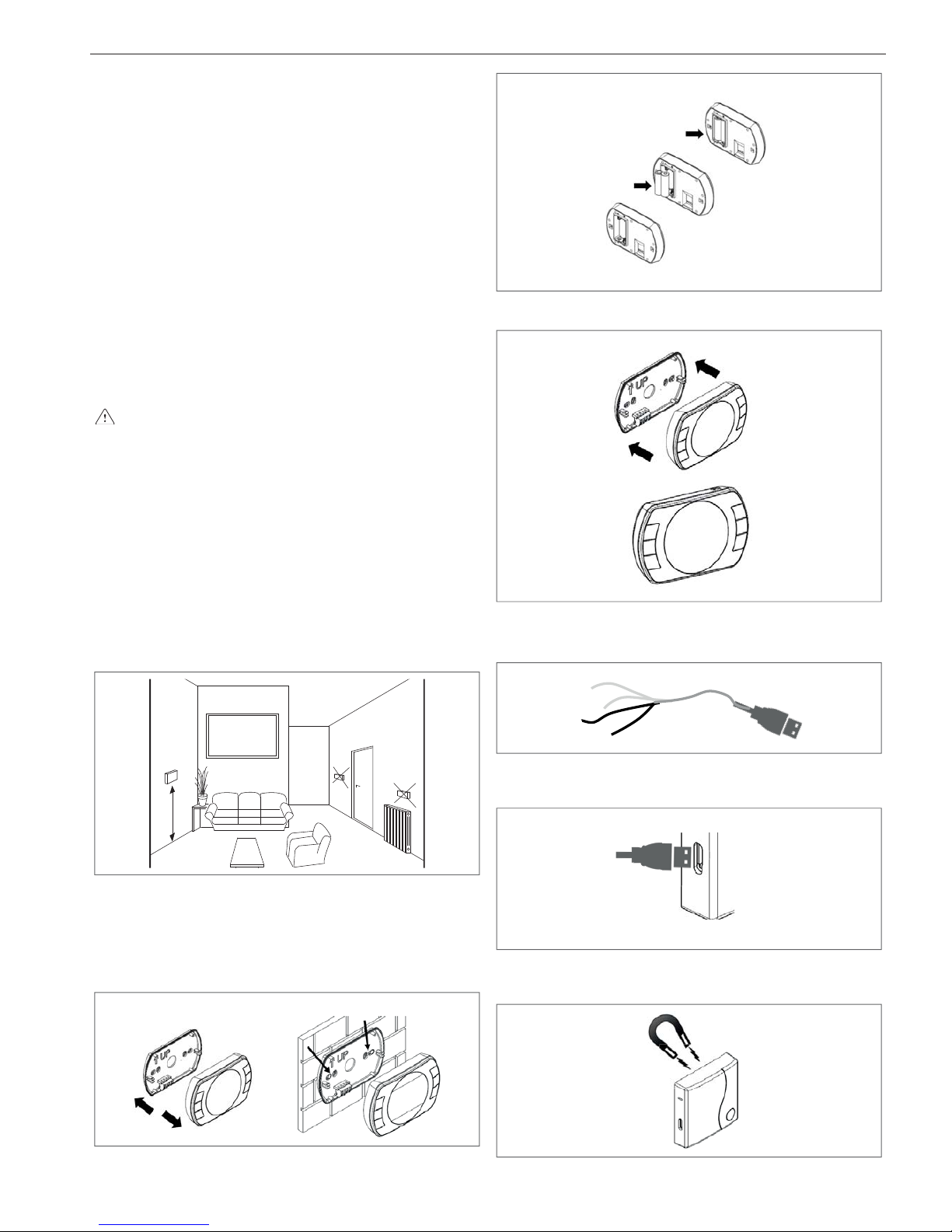
FIXING THE EXTERNAL PROBE TO THE WALL
The probe must be placed on a smooth part of the wall (Fig. 4); in the
case of exposed brickwork or an uneven wall, look for the smoothest
possible area. Loosen the plastic upper protective cover by turning
it anticlockwise.
After deciding on the best fixing area of the wall, drill the holes for the
5x25 wall plug.
Insert the plug in the hole. Remove the card from its seat.
Fix the box to the wall, using the screw supplied.
Attach the bracket, then tighten the screw.
Loosen the nut of the cable grommet, then insert the probe connection cable and connect it to the electric clamp.
To make the electrical connection between the external probe and
the boiler, refer to the “Electrical wiring” chapter.
Remember to close the cable grommet well, to prevent any air
humidity getting in through the opening.
Put the card back in its seat.
Close the plastic upper protective cover by turning it clockwise. Tighten the cable grommet very well.
3.7 Installation of the remote control panel
To correctly check the ambient temperature, the control panel
should be installed in a reference position in the home.
For a correct installation, keep in mind that the panel:
it should be installed on a wall, preferably not a perimeter one,
that has no hot or cold pipes running through it
It should be fi xed about 1.5 m from the ground
It should not be installed near doors or windows, cooking equip-
ment, radiators, fan coils or generally in conditions that might
alter the measured temperatures.
1,50 m
NO
NO
SI
In order to fi x the panel to the wall, proceed as follows:
separate the control panel from the base
use the base as a template for marking the fi xing points on the
wall
drill holes in the wall (ø 6 mm holes)
fi x the base to the wall using the screws supplied
Insert 2 type AA batteries;
attach the top part of the panel to the base
connect the red wires of the USB cable of the WiFi Box to the OT
clamp of the boiler - see wiring diagram
USB
TA = Black
OT = Red
connect the plug of the USB cable to the OUTPUTS/BOILER
output of the WiFi Box.
USB
OUTPUTS/BOILER
Put the WiFi Box onto the hood of the boiler using the magnet
on the back.
Position the WiFi Box in a place where the WiFi signal is not
weak (recommended above 30%).
YES
MySMART C.S.I.
7
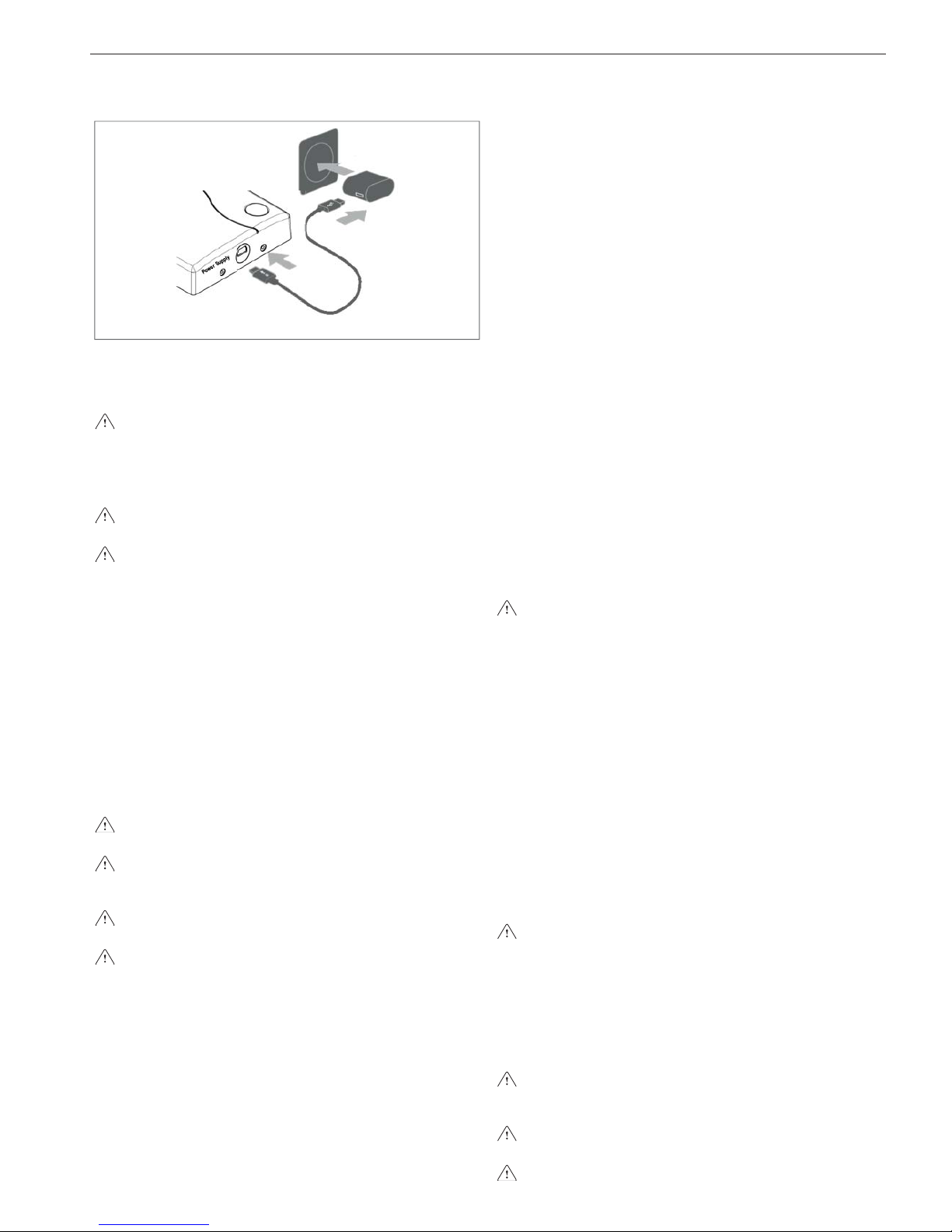
Power up the WiFi Box using the relative cable and power sup-
ply provided as standard.
3.8 Condensate collection
The discharge manifold (Fig. 5) collects condensate water, any evacuation water from the safety valve and the system discharge water.
The manifold must be connected via a rubber pipe (not provid-
ed) to an appropriate collection and evacuation system in the
white water discharge drain in compliance with current regulations. The outer diameter of the manifold is 20 mm: it is there-
fore advisable to use a rubber pipe Ø 18-19 mm closed with a
suitable clamp (not provided).
The manufacturer is not liable for any damage/flooding result-
ing from the failure to channel the condensate.
Sealing of the condensate drainage connection line must be
guaranteed.
3.9 Electrical wiring
To access the electrical wirings, proceed as follows:
To access the terminal board:
- set the system's main switch to off
- undo the fixing screws (D) of the shell (fig. 6)
- move the shell base forward and then upwards to unhook it from
the chassis
- lift and then turn the instrument panel upside down (fig. 7)
- remove the electrical parts inspection cover (fig. 8)
The connection to the mains supply must be made via a separation
device with an omnipolar opening of at least 3.5 mm (EN 60335/1,
category 3).
The appliance operates with an alternating current of 230 Volt/50 Hz
and complies with the standard EN 60335-1.
It is obligatory to make the connection with a safe ground/earth,
in compliance with current directives.
The installer is responsible for ensuring the appliance is suita-
bly earthed; the manufacturer will not be liable for any damage
resulting from an incorrect or absent earth connection
It is also advisable to respect the phase-neutral connection
(L-N).
The ground/earth wire must be a couple of cm longer than the
others.
The boiler can operate with a phase-neutral or phase-phase supply.
For power supplies that are not earthed, it is necessary to use an
isolating transfo
rmer with earth-anchored secondary.
It is forbidden to use gas and/or water pipes to earth electrical appliances.
Use the power cable supplied to connect the boiler to the mains power
supply.
If the power cable needs to be replaced, use a cable of the HAR
H05V2V2-F type, 3 x 0.75 mm², with a maximum external diameter of 7
mm (fig. 9).
3.10 Gas connection
Before connecting the appliance to the gas network, check that:
- current prevailing standards have been met
- the gas type is appropriate for the appliance
- the piping is clean.
The gas pipe must be installed outdoors. If the pipe has to pass
through the wall, it must pass through the central opening in the lower part of the template.
It is advisable to install a filter of suitable dimensions on the gas line
if the distribution network contains solid particles.
Once the appliance has been installed, check the connections are
sealed according to current installation regulations.
3.11 Flue gas exhaustion and air aspiration (fig. 10)
For flue gas discharge, refer to Standards UNI 7129-7131 and UNI
11071. Always comply with local standards of the Fire Department,
the Gas Company and with possible municipal dispositions.
The discharge of flue gas is guaranteed by the centrifugal fan located
inside the combustion chamber. The boiler is supplied without the
flue gas outlet/air suction kit, since it is possible to use the accessories for appliance with a forced draught sealed chamber that better
adapts to the installation characteristics.
It is essential for evacuating fumes and restoring boiler combustion
air that only original Riello pipes be used and that the connection is
made correctly as shown in the instructions provided with the flue
gas accessories.
A single smoke pipe can be connected to several appliances provided that every appliance is the condensing type
The boiler is a C-type appliance (with airtight chamber), and must
therefore have a safe connection to the flue gas discharge pipe and
to the combustion air suction pipe; these both carry their contents
outside, and are essential for the operation of the appliance.
Both concentric and twin terminals are available.
As envisaged by Standard UNI 11071, the boiler is designed to take
in and dispose of flue gas condensate and/or meteoric water condensate deriving from the flue gas discharge system. It does this via its
own drain-tap, if an external drain-tap is not fitted during the design
or installation phase.
if a condensate relaunch pump is installed, check the technical
data (provided by the manufacturer) regarding output, to ensure it operates correctly.
POSSIBLE OUTLET CONFIGURATIONS (fig. 11)
B23P-B53P - Suction in room, with external outlet.
C13-C13x - Concentric wall outlet. Pipes can leave the boiler inde-
pendently, but the outputs must be concentric or near enough in order to be subjected to similar wind conditions (within 50 cm)
C33-C33x - Concentric roof outlet. Output as C13.
C43-C43x - Discharge and suction in common, separate smoke
pipes, but subjected to similar wind conditions.
C53-C53x - Separate wall or roof outlet and suction line and in areas
with different pressures. Outlet and suction line must never be placed
on opposite walls.
C63-C63x - Outlet and suction line carried out with pipes marketed
and certified separately (1856/1).
C83-C83x - Outlet in single or regular smoke pipe and wall suction
line.
C93-C93x - Discharge on the roof (similar to C33) and air suction
from a single existing smoke pipe.
See the prevailing standards.
“FORCED OPEN” INSTALLATION (TYPE B23P/B53P)
Flue gas discharge pipe ø 80 mm (fig. 12)
The flue gas outlet pipe can be directed to the most suitable direction
according to installation requirements. For installation, follow the instructions supplied with the kit.
In this configuration, the boiler is connected to the flue gas outlet pipe
of ø 80 mm through an adaptor of ø 60-80 mm.
In this case, the combustion air is picked up from the boiler
installation room (which must be a suitable technical room with
proper ventilation).
The non insulated flue gas outlet pipes are potential sources of
danger.
Arrange the flue gas discharge pipe so it slopes by 3° towards
the boiler.

ENGLISH
8
The boiler automatically adapts the purging to the type of in-
stallation and the length of the pipe.
Maximum length of the flue gas
discharge pipe Ø 80 mm
Pressure loss
45° curve 90° curve
28 C.S.I. 80 m 1 m 1.5 m
“AIRTIGHT” INSTALLATION (TYPE C)
The boiler must be connected to concentric or twin flue gas discharge
pipes and air suction pipes, both leading outdoors. The boiler must
not be operated without them.
Concentric pipes (Ø 60-100 mm) (Fig. 13)
The concentric pipes can be fitted in most suitable direction in relation to installation requirements complying with the maximum lengths
show on the table.
Arrange the flue gas discharge pipe so it slopes by 3° towards
the boiler.
Non-insulated outlet pipes are potential sources of danger.
The boiler automatically adapts the purging to the type of in-
stallation and the length of the pipe.
Do not obstruct or choke the combustion air suction pipe in any
way.
For installation, follow the instructions supplied with the kit.
Horizontal
Max straight length of concentric
pipe Ø 60-100 mm
Pressure loss
45° curve 90° curve
28 C.S.I. 7.8 m 1.3 m 1.6 m
Vertical
Max straight length of concentric
pipe Ø 60-100 mm
Pressure loss
45° curve 90° curve
28 C.S.I. 8.8 m 1.3 m 1.6 m
"Straight length" means without bends, drainage terminals or
joints.
Concentric pipes (Ø 80-125 mm) (Fig. 14)
For this configuration the specific adaptor kit must be installed. The
concentric pipes can be fitted in most suitable direction in relation
to installation requirements. For installation, follow the instructions
supplied with the specific kits for condensing boilers.
Maximum straight length of
concentric pipe Ø 80-125 mm
Pressure loss
45° curve 90° curve
28 C.S.I. 20 m 1 m 1.5 m
"Straight length" means without bends, drainage terminals or
joints.
Twin pipes (Ø 80 mm) (Fig. 15)
The twin pipes can face in the direction most suitable for installation
requirements.
For installation, follow the instructions supplied with the specific accessory kit for condensation boilers.
Arrange the flue gas discharge pipe so it slopes by 3° towards
the boiler.
The boiler automatically adapts the purging to the type of in-
stallation and the length of the pipes. Do not obstruct or choke
the pipes in any way.
For the maximum length indications of the individual pipe see
the graphics (fig. 16).
The use of longer pipes reduces the boiler output.
Maximum straight length
of twin pipe Ø 80 mm
Pressure loss
45° curve 90° curve
28 C.S.I. 50+50 m 1 m 1.5 m
Ø 80 twin pipes with Ø 50,
Ø 6
0,
Ø 80
pipework (Fig. 17)
The characteristics of the boiler allow the Ø 80 flue gas discharge
pipe to be connected to the Ø 50, Ø 60
and
Ø 80 range of pipework.
For the pipework we recommend carrying out a design calcula-
tion in order to comply with the applicable prevailing standards.
The allowed base configurations are indicated in the table.
Base pipe configuration table (*)
Air suction 1 90° ø 80 curve
4.5 m ø 80 pipe
Flue gas exhaust 1 90° ø 80 curve
4.5 m ø 80 pipe
Reductio
n from ø 80 to ø 50 or ø 80 to ø 60
flue base curve 90° ø 50 or ø 60 or ø 80
for pipework pipe lengths see the table
(*) Use the plastic (PP) flue accessory systems for condensing boilers that can be found on the residential catalogue price list, ø 50 H1
class and ø 60 P1 class
The boilers leave the factory regulated to 6.100 r.p.m. for domestic
hot water and 4.500 r.p.m. for heating and the maximum achievable length is 6 m for the pipe ø 60, 0,5 m for the pipe ø 50 and 35
metres for the pipe ø 80.
If you need to reach greater lengths compensate for the pressure
drop with an increase of the number of fan rotations as shown in the
adjustments table in order to guarantee the rated heat input.
The minimum calibration must not be modified.
If the prevailing value is greater than 200 Pa the law requires the use
of H1 pressure class flue accessories
MySMART adjustments table
Maximum
number of fan
rotations
rpm
Ø 50 pipework
pipes
maximum
length
Ø 60 pipework
pipes
maximum
length
Ø 80 pipework
pipes
maximum
length
ΔP at the boiler
output with
max length (°)
DHW CH m
m
mPa
6.100 4.500 0,5 6 35 80
6.200 4.600 3 15 82 130
6.300 4.700 7(*) 26(*) 141(*) 194
(*) Compatible length with P1 class pipes
NOTE
If p
ipes different than those in the Beretta catalogue are used you must
see the ΔP values on the above tables to calculate the maximum length
of the pipes.
The Ø 60 and Ø 50 configurations have experimental, laboratory checked
data.
In the event of installations other than those indicated in the “base
configurations” and “adjustments” table, see the equivalent Ø 80 - Ø
60 or Ø 50 linear lengths shown below.
In any case the maximum lengths declared in the booklet are
guaranteed and it is essential that they are not exceeded.
Ø 60 component
Linear equivalent in
metres Ø 80 (m)
45° Ø 60 curve 5
90° Ø 60 curve 8
0.5 m Ø 60 extension 2.5
1.0 m Ø 60 extension 5.5
2.0 m Ø 60 extension 12
Ø 50 COMPONENT Linear equivalent in
metres Ø 80 (m)
45° Ø 50 curve
12,3
90° Ø 50 curve 19,6
0.5 m Ø 50 extension 6,1
1.0 m Ø 50 extension 13,5
2.0 m Ø 560 extension 29,5
MySMART C.S.I.
9
3.13 Installation on collective flues in positive
pressure
The collective flue is a gas discharge system suitable for collecting
and expelling the combustion products of several appliances installed on several floors of a building (fig. 18).
The collective flues in positive pressure can be used only for type C
condensing appliances. Consequently the B53P/B23P configuration
is not permitted.
Installation of the boiler on collective flues in pressure is permitted
only at G20 using a specific check valve, supplied as an accessory.
See the related instructions for the assembly procedure.
The boiler is sized to operate correctly up to a maximum internal
pressure of the smoke pipe no higher than the value shown in the
multigas table.
Complete the check valve assembly operations and proceed with
adjustment of the number of fan rotations as shown in the multigas
table.
Ensure that the air suction pipes and combustion product outlet are
airtight.
Installation of the check valve (fig. 19) requires the application of the
ATTENTION label that comes with the same accessory on a visible
part of the boiler shell. Applying the label is essential for safety during
maintenance or replacement of the boiler and/or the collective flue.
WARNINGS
The manufacturer will not be liable in the event of failure to
apply the check valve and the related label prior to placing the
boiler in service.
The appliances connected to a collected flue must all be of the
same type and have equivalent combustion characteristics.
The number of appliances that can be connected to a collective
flue in positive pressure is defined by the smoke pipe designer.
MAINTENANCE FOR APPLICATION IN A COLLECTIVE FLUE
UNDER PRESSURE
During scheduled maintenance on the appliance you must also
check the condition of the check valve in order to guarantee correct
operation and safety of the system.
Before proceeding with maintenance you must conduct an analysis
of the combustion product and check the boiler operating status.
In the event of maintenance on the boiler's combustion circuit
(gas discharge pipes, condensate syphon, burner, electrode
conveyors) you must close the gas discharge pipe that comes
from the smoke pipe under pressure and check the seal.
Subsequently:
- Remove electrical power by setting the system's main switch to
“off”
- Close the gas interception taps
- Remove the shell
- Unhook the instrument panel and rotate it downward
- Unhook and remove the air box cover
- After undoing the related fixing screws, remove the right side of
the air box
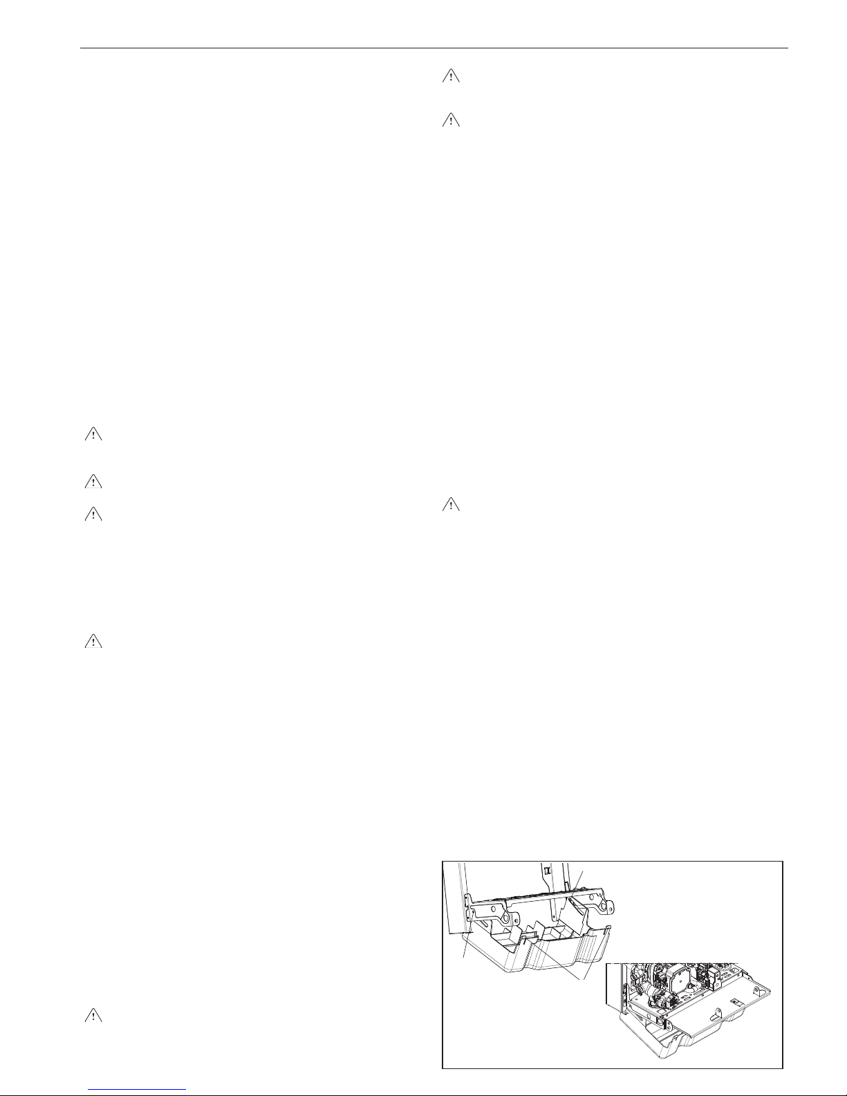
- Undo the nut that secures the gas train valve to the air box
- Undo and remove the mixer connection gas train (A, fig. 20)
- Remove the ignition electrode and flame detection electrical con-
nections and the fan electrical connections
- Undo the 4 screws that secure the air gas conveyor to the main
heat exchanger (B, fig. 20)
- Remove the conveyor-fan assembly from the heat exchanger (C,
fig. 20), taking great care not to damage the burner insulating panel
- To access the check valve remove the fan by undoing the 4 screws
(D, fig. 21) that secure it to the conveyor
- Ensure that there is no material deposited on the check valve
membrane and remove any you may find, ensuring there is no
damage.
- Check the correct opening and closing operation of the valve
- Reassemble the components working in reverse order, ensuring
that the check valve is reassembled in the correct direction (see
fig. 21)
Failure to observe the above may lead to abnormal operation
of the check valve and consequent differences in the boiler's
performance, up to failure to operate.
Failure to observe what is described here may compromise the
safety of people and animals due to possible carbon monoxide
leaks from the smoke pipe.
Once the operations have been completed, carefully check all
the combustion product exhaust and air suction pipe seals,
conducting a combustion analysis.
NOTE
If the fan is removed ensure that the check valve is reassembled in
the correct direction (see fig. 21).
3.14 Filling the heating system (fig. 22-23-24)
Once the hydraulic connections have been carried out, fill the heating
system.
This operation must be carried out with a cold system, following
these instructions:
- open the lower automatic relief valve cap (A) by two or three turns
to allow continuous air venting and leave it open
- ensure that the cold water inlet tap is open
- open the filling tap (C) until the pressure indicated on the water
gauge is between 1 bar and 1.5 bar
- re-close the filling tap.
NOTE
deareation of the boiler takes place automatically by means of the
two automatic A and E bleed valves, the former positioned on the
circulator whereas the latter is positioned inside the air box. If the
deareation phase is difficult, operate as described in section 5.3.
3.15 Emptying the heating system
Before starting emptying, switch off the electricity supply by turning
off the main switch of the system.
- Close the heating system shut-off devices
- Slacken the discharge system valve by hand (D)
- The system's water is discharged through the discharge manifold (F).
The discharge manifold must be connected via a rubber pipe
to an appropriate collection and evacuation system in the white
water discharge drain in compliance with current regulations.
The outer diameter of the manifold is 20 mm: it is therefore advisable to use a rubber pipe Ø18-19 mm closed with a suitable
clamp (not provided).
3.16 Emptying the domestic hot water circuit
When there is risk of frost, the domestic hot water system must be
emptied in the following way:
- close the water mains tap
- open all the hot and cold water taps
- empty the lowest points.
3.17 Cover connections
The installation completed, it is possible to apply the cover connections as shown below:
- position the cover connections so that the lateral slots are in cor-
respondence with the holes (A) present on the bracket
- using anchor bolts supplied, secure from the inside the cover to
the shell.
Do not tighten the pins in the bottom, but leave a suffi cient space
to allow the cover to rotate.
- rotate upwards and slide the cover towards the wall till the limit
To open the cover connections act as described below:
- press cover by releasing the hooks (B) that hold it in place pull it
towards you
- push it down.
In this way you have the full access to the taps and fi ttings.
B
A
A
3.12
3.13
3.14
3.15
3.16

ENGLISH
10
4 - IGNITION AND OPERATION
4.1 Preliminary checks
When the boiler is first started the siphon for collecting the con-
densate is empty.
It is therefore necessary to create a head of water fi lling the siphon
before starting up, following these instructions:
- remove the siphon by releasing it from the plastic pipe connecting
to the combustion chamber
- fi ll the siphon about 3/4” full with water, making sure it is free of
any impurities
- check the fl oat of the plastic cylinder
- put back the siphon, being careful not to empty it, and secure it
with the clip.
The plastic cylinder inside the siphon has the job of preventing combustible gas coming out into the surroundings if the appliance is started without fi rst creating the head of water in the siphon.
Repeat this operation during routine and extraordinary maintenance
operations.
First ignition is carried out by competent personnel from an authorised Technical Assistance Service Centre.
Before starting up the boiler, check:
a) that the supply networks data (electric, water, gas) corresponds
to the label data
b) that piping leaving the boiler is covered by thermal insulation
sheath
c) that flue gas extraction and air suction pipes work correctly
d) that conditions for regular maintenance are guaranteed if the
boiler is placed inside or between furniture
e) the seal of the fuel adduction system
f) that fuel capacity corresponds to values requested by the boiler
g) the correct calibration of the gas valve and, if necessary, adjust
as indicated in paragraph 4.7 “Adjustments”
h) that the fuel supply system is sized to provide the correct deliv-
ery to the boiler, and that it has all the safety and control devices
prescribed by national and local regulations.
4.2 Appliance ignition
Each time the boiler is electrically powered the display shows a series of information including the gas probe counter value (-C- XX)
(see section 4.4 - fault A09) and then the boiler begins an automatic
venting cycle that lasts about 2 minutes. During this phase the symbol
will appear on the display (fig. 25).
To interrupt the automatic venting cycle: access the electronic card
by removing the shell, turning the instrument panel upside down and
opening the electrical parts inspection cover. Subsequently:
- press the CO button (fig. 26).
Live electrical parts (230 Vac).
To start-up the boiler it is necessary to carry out the following operations:
- electrically power the boiler
- unhook the connections cover as indicated in section 3.16 “Con-
nections cover”
- open the gas tap to allow fuel flow
- set the ambient thermostat at the required temperature (~20°C)
- turn the mode selector to the desired position:
Winter
Turning the mode selector (fig. 27) within the area marked with + and
- the boiler provides domestic hot water and heating.
The boiler lights automatically in response to a heat request.
The digital monitor indicates the heating water temperature (fig. 28).
In the event of a request for domestic hot water.
The display indicates the domestic hot water temperature (fig. 29).
Adjusting the heating water temperature
To adjust the heating water temperature, turn the knob with the “
” symbol (fig. 27) clockwise to the area marked with + and -.
Depending on the type of system, the most suitable temperature
range can be pre-selected:
- standard installations 40-80°C
- floor installations 20-45 °C.
For details see section 4.5.
Summer
Turning the selector to the
summer symbol (fig. 30) the traditional
function of only domestic hot water is activated.
The boiler lights automatically in response to a request for domestic
hot water.
The digital monitor indicates the domestic hot water temperature
(fig.29).
Pre-heating (faster hot water)
Positioning the mode selector to summer or winter and turning the
domestic hot water temperature adjustment knob to the
symbol
(fig. 31) the pre-heating function is activated. Bring the domestic hot
water temperature adjustment knob back to the required position.
This function keeps the water in the domestic hot water exchanger
hot, to reduce standby times when a request is made.
The display indicates the outlet temperature of the heating water or
the domestic hot water based upon the request in progress.
During burner ignition following a pre-heating request, the monitor
indicates the
symbol.
To deactivate the pre-heating function, rotate the domestic hot water
temperature adjustment knob back to the symbol
.
Bring the domestic hot water temperature adjustment knob back to
the required position.
This function cannot be activated when the boiler is OFF: mode selector (fig.32) on
OFF.
Adjusting the heating water temperature with an external probe
connected
When an external probe is installed, the delivery temperature is automatically selected by the system, which quickly adjusts the ambient
temperature according to variations in the outside temperature.
If you want to alter the temperature value (increasing or reducing
the value automatically calculated by the electronic card), use the
heating water temperature selector: turn it clockwise to increase the
temperature, or anticlockwise to reduce it.
The correction possibility is between - 5 and + 5 comfort levels which
are shown on the digital display by rotating the knob.
Adjustment of the domestic hot water temperature
To adjust domestic water temperature (bathrooms, showers, kitchen, etc.), turn the knob with the
symbol (fig. 33) within the area
marked with + and -.
The boiler is in standby until the burner switches on following a heat
request.
The boiler continues to function until the temperatures set on the
boiler are reached, or the heat request terminates; it will then go back
to standby.
If the red indicator light near the
symbol (fig. 34) on the command
panel lights up, this means the boiler is in temporary stop status (see
the chapter on light signals and faults).
The digital monitor indicates the fault code detected (fig. 34).
Automatic Ambient Adjustment System (S.A.R.A.) (fig. 35)
By setting the heating water temperature selector to the area marked
by AUTO, the S.A.R.A. self-adjusting system is activated (frequency
0.1 sec. on; - 0.1 sec. off; duration 0.5): according to the temperature
set on the ambient thermostat and the time employed to reach it,
the boiler varies automatically the heating water temperature reducing the operating time, allowing great operation comfort and energy
saving.
Reset function
To restore operation, set the function selector to
off (fig. 36), wait
5-6 seconds then bring it to the required position, checking that the
red indicator light is off.
At this point the boiler will automatically start and the red lamp switches on in green.
When a remote control BeSMART is connected, the reset of faults
can be done also on the remote control itself, pressing for one second the BACK/RESET (button) (fi g. 37).
N.B. If the attempts to reset the appliance do not activate operation,
contact the Technical Assistance Centre.
MySMART C.S.I.
11
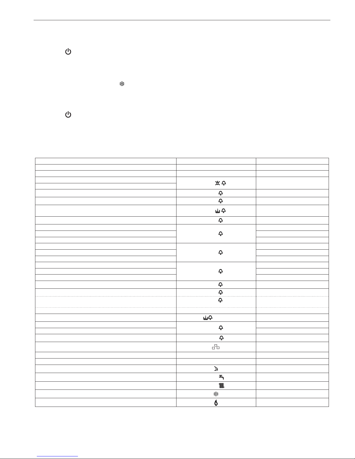
4.4 Faults
BOILER STATUS DISPLAY TYPES OF ALARMS
Off status(OFF) OFF None
Stand-by - Signal
ACF alarm lockout module
A01
Definitive lockout
ACF electronics fault alarm
Limit thermostat alarm
A02
Definitive lockout
Tacho fan alarm
A03
Definitive lockout
Water pressure switch alarm
A04
Definitive lockout
NTC domestic water fault
A06
Signal
NTC heating outlet fault
A07
Temporary stop
Heating outlet probe over-temperature Temporary then definitive
Outlet/return line probe differential alarm Definitive lockout
NTC heating return line fault
A08
Temporary stop
Heating return line probe over-temperature Temporary then definitive
Outlet/return line probe differential alarm Definitive lockout
Cleaning the primary heat exchanger
A09
Signal
NTC flue gases fault Temporary stop
Flue gases probe over-temperature Temporary then definitive
Parasite flame
A11
Temporary stop
Low temperature system thermostat alarm
A77
Temporary stop
Exceeded the maximum number of RESET by remote control
(Reset possible only by boiler control panel)
A99
Definitive lockout
Temporary pending ignition 80°C flashing Temporary stop
Water pressure switch intervention
flashing
Temporary stop
Calibration service
ADJ
Signal
Calibration installer
Chimney sweep
ACO
Signal
Vent cycle Signal
Pre-heating enabled P Signal
Preheating heat request P flashing Signal
External probe presence
Signal
Domestic water heat request
60°C
Signal
Heating heat request
80°C
Signal
Antifreeze heat request Signal
Flame present Signal
4.3 Switch-off
Temporary switch-off
In the event of absence for short periods of time, set the mode selector (fig. 36) to
(OFF).
In this way (leaving the electricity and fuel supplies enabled), the
boiler is protected by the following systems:
Antifreeze: when the temperature of the water in the boiler drops
below 5°C the circulator starts and, if necessary, the burner at minimum output to bring the water temperature to safety values (35°C).
During the anti-frost cycle, the symbol
(fig. 38) appears on the
digital monitor.
Circulator antiblocking: an operation cycle is activated every 24 h.
Switching off for long periods
In the event of absence for long periods of time, set the mode selector (fig. 36) to
(OFF).
Turn the main system switch OFF.
Turn off the fuel and water taps of the heating and domestic hot water
system. In this case, anti-frost device is deactivated: empty the systems, in case of risk of frost.

ENGLISH
12
To restore the functioning after the appearance of a fault code of
the boiler press for a second the button BACK/RESET .
If the reset attempts do not reactivate the boiler, request the intervent
of the Technical Assistance Centre.
The A99 fault code means that you have exceeded the maximum
number of reset possible by remote control BeSmart.
In this case, the operations of RESET must be carried out ONLY
from the panel of the boiler as indicated below:
- set the mode selector to
(OFF), wait 5-6 seconds and then return
it to the Desired position (summer) or (winter).
Fault A 04
Anomalia A 04
Check the pressure value indicated by the manometer, if less than
0.3 bar position the function selector to
(OFF) and turn the tap
to fi ll the boiler until the pressure reaches a value of between 1 and
1.5 bar.
Then press the
BACK/RESET button.
If pressure drops are frequent, request the intervention of the
Technical Assistance Centre.
Fault A 06
The boiler functions normally but does not guarantee a constant domestic hot water temperature, which remains set at around 50°C.
Contact the Technical Assistance Centre.
Fault A 07
Contact the Technical Assistance Centre.
Fault A08
Contact the Technical Assistance Centre.
Fault A09
The boiler is equipped with an auto-diagnostic system which, based
on the total number of hours in certain operating conditions, can signal the need to clean the primary exchanger (alarm code 09 with flue
gases probe counter >2.500).
Once the cleaning operation has been completed, reset to zero the
total hour meter with special kit supplied as an accessory following
procedure indicated below:
disconnect the electrical supply;
remove the shell and turn the instrument panel;
remove the electrical parts inspection cover, undoing the 2 fixing
screws;
as you electrically power the boiler press the CO button for at least 4
seconds to check that the counter resets. Remove and restore power to the boiler; on the display the counter is shown after the “-C-”
indication.
Live electrical parts (230 Vac).
NOTE
The meter resetting procedure should be carried out after each indepth cleaning of the primary exchanger or if this latter is replaced.
To check the status of the totalled hours multiply the value shown by
100 (ex: shown value of 18 = pre totalled 1.800 – shown value of 1=
totalled hours 100). The boiler continues to operate normally even
with the alarm active.
Fault A77
The fault is self-resetting, if the boiler does not restart contact the
Technical Assistance Centre.
4.5 Boiler configuration
On the electronic card there is a series of jumpers (JPX) which allow
the boiler to be configured; access is possible by removing the electrical parts inspection cover after setting the main switch to off.
To access the card operate as follows:
- set the system's main switch to off
- undo the shell fixing screws, then move the shell base forward and
then upwards to unhook it from the chassis
- lift and then turn the instrument panel upside down
- remove the electrical parts inspection cover, undoing the 2 fixing
screws to access the jumpers (fig. 39)
JUMPER JP7 - fig. 40
pre-selection of the most appropriate boiler heating temperature adjustment field depending on the type of system.
Jumper not on - standard system
Standard system 40-80 °C.
Jumper on - floor system
Floor system 20-45 °C.
From the factory the boiler is configured for standard systems.
JP1 Enabling front knobs for calibration
JP2 Heating timer reset
JP3 Calibration (see “Adjustments” section)
JP4 Absolute domestic hot water thermostat selector
JP5 do not use
JP6
Enable night-time compensation function and pump in
continuous mode (only with external probe connected)
JP7
Enable standard/low temperature systems
management (see above)
JP8 Do not use
4.6 Setting the thermoregulation
Thermoregulation works only with the external probe connected,
therefore, once installed, connect the external probe to the specific
connection provided on the boiler terminal board.
This enables the THERMOREGULATION function.
Choice of the compensation curve
CURVE DI TERMOREGOLAZIONE
Temperatura esterna (˚C)
Temperatura di mandata (˚C)
20
30
40
50
60
70
80
90
100
-20
0,2
0,4
0,6
0,8
1,0
1,5
2,02,53,0
T80
T45
-15-10-505101520
THERMOREGULATION CURVES
Outside temperature [°C]
Delivery temperature [°C]
T80 - maximum std system heating set point temperature
(JP7 not on)
T45 - maximum floor system heating set point temperature
(JP7 on)
the display shows the value of the KT curves multiplied by 10
(example 3.0 = 30)
The compensation curve for heating maintains a theoretical temperature of 20°C indoors, when the external temperature is between
+20°C and -20°C. The choice of the curve depends on the minimum
external temperature envisaged (and therefore on the geographical
location), and on the delivery temperature envisaged (and therefore
MySMART C.S.I.
13
on the type of system). It is carefully calculated by the installer on the
basis of the following formula:
KT =
Design delivery temp - Tshift
20 - Design min outside temp
Tshift = 30 °C standard system
25 °C floor system
If the calculation produces an intermediate value between two
curves, you are advised to choose the compensation curve nearest
the value obtained.
Example: if the value obtained from the calculation is 1.3, this is between curve 1.0 and curve 1.5. Choose the nearest curve, i.e. 1.5.
Selection of the KT must be made by acting on the P3 trimmer on the
card (see multi-wire electrical diagram).
To access P3:
1. remove the shell,
2. turn the instrument panel upside down
- remove the electrical parts inspection cover, undoing the 2 fixing
screws
Live electrical parts (230 Vac).
The following KT values can be set:
- standard system: 1.0 - 1.5 - 2.0 - 2.5 - 3.0
- floor system: 0.2 - 0.4 - 0.6 - 0.8
and they will be shown on the display for about 3 seconds after the
P3 trimmer is turned,
TYPE OF HEAT REQUEST
If an ambient thermostat is connected to the boiler (JUMPER 6
not on) (fig. 41)
The heat request is made by the closure of the room thermostat contact, while the opening of the contact produces a switch-off. The delivery temperature is automatically calculated by the boiler, although
the user may interact with the boiler. Using the interface to modify the
HEATING, you will not have the HEATING SET-POINT value available, but a value that you can set as preferred between 15 and 25°C.
The modification of this value will not directly modify the delivery temperature, but will automatically affect the calculation that determines
the value of that temperature, altering the reference temperature in
the system (0 = 20°C).
If an hourly timer is connected to the boiler (JUMPER JP6 not
on) (fig. 42)
With the contact closed, the heat request is made by the delivery
probe, on the basis of the external temperature, to obtain a nominal
ambient temperature on DAY level (20°C). The opening of the contact does not produce a switch-off, but a reduction (parallel translation) of the climatic curve on NIGHT level (16°C).
This will activate the night time function.
The delivery temperature is automatically calculated by the boiler,
although the user may interact with the boiler.
Using the interface to modify the HEATING, you will not have the
HEATING SET-POINT value available, but a value that you can set
as preferred between 15 and 25°C.
The modification of this value will not directly modify the delivery temperature, but will automatically affect the calculation that determines
the value of that temperature, altering the reference temperature in
the system (0 = 20°C for DAY level, and 16°C for NIGHT level).
If the boiler is connected to a remote control (like BeSmart), when
the heat request is made by the REC remote control, the thermoregulation is managed by said remote control (refer to the specifi c instruction manual for this product).
4.7 Adjustments
All boiler regulations and calibrations should be carried out directly and only on the instrument panel in the boiler.
To do this, remove the connection of the remote control panel
by separating the front of the fixing base. After this operation the
knobs of the boiler are active.
The boiler has already been adjusted by the manufacturer. However,
if adjustments must be repeated, for example after special maintenance, replacement of the gas valve or conversion from methane gas
to LPG or propane air, observe the following procedures.
The adjustment of the maximum and minimum output, the maximum
heating and slow ignition, must be made strictly in the sequence indicated, and by qualified personnel only:
1. disconnect the boiler power supply
2. turn the heating water temperature selector to its maximum, selector in correspondence to + (fig. 43)
3. lift and then turn the instrument panel upside down
4. remove the electrical parts inspection cover, undoing the 2 fixing
screws
5. insert jumpers JP1 and JP3 (fig. 44)
6. power the boiler.
“ADJ” will appear on the display for about 4 sec
Modify the following parameters:
7. absolute/domestic maximum
8. minimum
9. maximum heating
10. slow ignition
as described below:
11. turn the heating water temperature selector to set the desired
value
12. press the CO button (fig. 45) and move on to calibration of the
next parameter.
Live electrical parts (230 Vac).
The following icons will appear on the display:
1.
during absolute/domestic maximum calibration
2. during minimum calibration
3. during heating maximum calibration
4.
during slow ignition calibration
End the procedure removing jumpers JP1 and JP3 to store the set
values.
the function can be terminated at any time without storing the set
values and maintaining the previously set ones:
removing jumpers JP1 and J
P3 before all 4 parameters have been set
- turning the mode selector to OFF/RESET.
- disconnecting the mains voltage.
- 15 minutes after activation.
The calibration does not entail the ignition of the boiler.
By rotating the heating setpoint selector knob, the number of ro-
tations expressed in hundreds (e.g. 25 = 2.500 rpm) is automatically displayed.
The calibration parameter display function is activated with the selector
on summer or winter and pressing the CO button on the card regardless of whether or not there is a heat request.
The function cannot be activated if a remote control is connected.
When this function is activated, the calibration parameters each appear
(in the order shown below) for 2 seconds. The relative icon is indicated
in line with each parameter, and the fan rotation value (expressed in
hundreds)
1. Maximum
2. Minimum
3. Maximum heating
4. Slow ignition
5. Adjusted maximum heating
GAS VALVE CALIBRATION
- Electrically power the boiler.
- Open the gas tap.
- Set the mode selector to
OFF/RESET (display off).
- Remove the shell, turn the instrument panel upside down and re-
move the electrical parts inspection cover to access the “CO” button.
Press the “CO” button once.
Live electrical parts (230 Vac).
- Wait for the burner to ignite.
“ACO” appears on the display. The boiler operates at maximum
heating output.
The “combustion analysis” function remains active for a limited
time of 15 minutes; if a delivery temperature of 90°C is reached the
burner will extinguish. It will reignite when this temperature drops
b
elow 78°C.
- insert the analyser probes in the prescribed positions on the air box
after removing the screws and the cover.
- Press the “combustion analysis” button a second time to reach the
number of revolutions that corresponds to the maximum domestic
hot water output (table 1).
- Check the CO
2
value: (table 4) if the value does not comply with the
indications in the table act on the gas valve max adjustment screw
(fig. 46).

ENGLISH
14
- Press the “combustion analysis” button a third time to reach the number of revolutions that corresponds to the minimum output (table 2).
- Check the CO
2
value: (table 5) if the value does not comply with the
indications in the table act on the gas valve min adjustment screw
(fig. 46).
- To exit the “combustion analysis” function turn the command knob.
- Extract the gases analysis probe and refit the plug.
- Close the instrument panel and reassemble the shell.
The “combustion analysis” function automatically deactivates if the
card generates an alarm. In the event of a fault during the combustion
analysis phase, carry out the reset procedure, acting on the mode se-
lector as described in section 4.4.
Table 1
Maximum domestic hot
water fan rotations
Methane
gas (G20)
Liquid gas
(G31)
28 C.S.I. 61 61 rpm
Table 2
Minimum number of fan
rotations
Methane
gas (G20)
Liquid gas
(G31)
28 C.S.I. 12 15 rpm
Table 2a
Minimum number of fan
rotations in case of collective
smoke pipes under pressure
Methane
gas (G20)
Liquid gas
(G31)
28 C.S.I. 18 19 g/min
Table 3
Maximum number of
heating fan rotations
Methane
gas (G20)
Liquid gas
(G31)
28 C.S.I. 45 45 rpm
Table 4
Max CO
2
Methane
gas (G20)
Liquid gas
(G31)
28 C.S.I. 9.0 10.0 %
Table 5
Min CO
2
Methane
gas (G20)
Liquid gas
(G31)
28 C.S.I. 9.0 10.0 %
Table 6
Slow ignition
Methane
gas (G20)
Liquid gas
(G31)
28 C.S.I. 33 33 %
4.8 Gas conversion (fig. 47)
It is easy to transform gas from one family to gas belonging to another
family even with the boiler installed.
This job must be done by professionally qualifi ed personnel only.
The boiler is supplied to run on natural gas (G20) – see the product
rating plate for details.
The boiler can be transformed to use propane gas using a special kit.
Follow the instructions given here below for disassembly:
- Switch off the power to the boiler and turn off the gas cock.
- Remove the panel and casing.
- Lift up and rotate the instrument panel.
- Open the air box cover.
- Unscrew the screws fastening the silencer (A) and remove it.
- Disconnect the mixer gas ramp. Unscrew the clamp screws and
relative mixer springs to fan and then remove it.
- Loosen the plastic Venturi (B) by levering from under the teeth (BE
CAREFUL NOT TO FORCE THEM) and press from the opposite
side until it is completely extracted from the aluminium shell.
- Replace the plastic Venturi with the one contained in the kit.
- Reassemble the mixer with the fl ap in a horizontal position and
the spacer springs placed at 120° as shown in the fi gure.
- Reassemble gas ramp working vice versa.
- Switch on the power to the boiler and turn on gas cock again.
- Check the number of times the fan turns.
- Fill in and stick on the accompanying transformation data label.
- Close the air box cover.
- Close up the instrument panel again.
- Reassemble the casing and panel.
Programme the “Gas type” parameter and regulate the boiler following the instructions in the “Adjustments” section.
Transformation must be done by qualifi ed personnel only.
After completing transformation, regulate the boiler again
following instructions given in the specifi c paragraph and
apply the new identifi cation label from the kit.
Check that fl ap and Clapet are working correctly (all open
at rated fl ow, all closed at minimum fl ow)
RANGE RATED
This boiler can be adapted to the heating requirements of the system,
in fact it is possible to set the maximum delivery for heating operation
of the boiler itself:
- switch off the power supply
- setting the heating water temperature selector at the maximum value
- remove the shell
- turning the instrument panel towards you
- unscrew the two screws of the small cover on the electronic board to
have access to the terminals
- insert JP1 jumper
- power up the boiler.
The display shows “ADJ” for about 4 sec.: it is then possible to change
the maximum heating value by means of the heating water temperature
selector and the CO button in order to set and confirm the desired
value.
The icon
will appear on the display.
Finish the procedure by removing the jumper JP1 to store the set
values.
Once the desired output (maximum heating) has been set, note the
value on the table on the back cover.
For subsequent controls and adjustments, refer to the set value.
The calibration does not entail the ignition of the boiler. By rota-
ting the heating setpoint selector knob, the value expressed in
hundreds (e.g. 25 = 2500 rpm) is automatically displayed.
The boiler is supplied with the adjustments shown in the table.
Depending on plant engineering requirements or regional flue gas
emission limits it is, however, possible to modify this value, referring
to the graphs.
CO s.a. curve (Qnheating)
0
10
20
30
40
50
60
70
80
90
100
110
120
130
140
150
160
170
180
190
200
210
220
230
240
24681012141618202224262830
HTG curve (Qnheating)
F
an rotat
i
ons
(
rpm
)
Heat output (kW)
CO emissions s.a. (p.p.m.)
Heat output (kW)
800
1200
1600
2000
2400
2800
3200
3600
4000
4400
4800
5200
5600
6000
6400
2 4 6 8 10 12 14 16 18 20 22 24 26 28 30

MySMART C.S.I.
15
5 - MAINTENANCE
To ensure product characteristics and efficiency remain intact and
to comply with prescriptions of current regulations, it is necessary to
render the appliance to systematic checks at regular intervals.
When carrying out maintenance work, observe the instructions given
in chapter 1 “Warnings and safety”.
Turn off the appliance before carrying out work or maintenance of
structures near the flue discharge connections and/or fume discharge devices and their accessories. Once work is completed, a
qualified technician must check the efficiency of the appliance.
IMPORTANT: before undertaking any maintenance or cleaning operations, use the switch of the appliance itself and the system to
interrupt the electrical supply and close the gas supply using the
tap on the boiler.
IT IS also OBLIGATORY
to disconnect the cable connecting the
WiFi Box and the boiler
return power to the boiler
interrupt the vent cycle as described in the section “4.2 Appliance
ignition” on page 10.
5.1 Routine maintenance
This normally means the following tasks:
- removing any oxidation from the burner;
- removing any scale from the heat exchangers;
- checking and cleaning the drainage pipes;
- checking the external appearance of the boiler;
- checking the ignition, switch-off and operation of the appliance, in
both domestic water mode and heating mode;
- checking the seal on the gas and water couplings and pipes;
- checking the gas consumption at maximum and minimum output;
- checking the position of the ignition-flame detection glowplug;
- check the “no gas” safety system;
- check operation of the check valve if it is installed (see section 3.12
“Installation on collective flues in positive pressure”).
cleaning the filter inside the heating return line tap. Follow the
instructions below:
- set the lever to “filter cleaning“
- unscrew plug A
- remove the filter B and clean it
- remove any dirt in the filter chamber
- put back the filter
- put back the plug A
- set the lever to the opening position
opening
position
closing
position
fi lter cleaning
position
A
B
- Do not clean the appliance or its parts with easily inflammable
substances (e.g. benzine, alcohol, etc.).
Do not clean panels, painted parts and plastic parts with paint thinner.
Panel cleaning must be carried out only with soapy water.
After routine and extraordinary maintenance operations have
been carried out, fi ll the siphon, following the instructions in the
section “Preliminary cheks”.
5.2 Extraordinary maintenance
These tasks restore appliance operation in accordance with the design and regulations - e.g. following the repair of an accidental fault.
This normally means:
- replacement
- repair
- overhaul of components.
These tasks require special means, equipment and tools.
During the initial
installation phase, or in the event of extraordinary maintenance, you are advised to activate the procedure to
discharge air from the heating circuit and boiler (see section 3.4).
5.3 Checking the combustion parameters
To carry out the combustion analysis, proceed as follows:
- Set the mode selector to to switch off the boiler (fig. 48)
- Turn the domestic hot water temperature selector to the position
(fig. 48)
- Wait for the burner to ignite (about 6 seconds). The display shows
“ACO” and the boiler operates at maximum heating output
- Remove the screw C and the cover E on the air box (see fig. 49)
- insert the analyser probes in the prescribed positions on the air box
The flue gas analysis probe should be inserted until its reaches
the stop.
- Check that the CO2 values correspond to the ones indicated in the
tables shown below”; if the value shown is different proceed with
changes as indicated in the “Gas valve calibration” chapter.
Max CO
2
Methane
gas (G20)
Liquid gas
(G31)
28 C.S.I. 9.0 10.0 %
Min CO
2
Methane
gas (G20)
Liquid gas
(G31)
28 C.S.I. 9.0 10.0 %
- Perform the combustion check.
The “combustion analysis” function remains active for a limited
time of 15 minutes; if a delivery temperature of 90°C is reached the
burner will extinguish. It will reignite when this temperature drops
below 78°C.
- If you want to interrupt the procedure turn the domestic hot water
temperature selector so that it is within the + and - symbols.
Subsequently:
- remove the analyser probe and close the combustion analysis inlet
- close the instrument panel and refit the shell
When checks are completed:
- Position the knobs depending on the type of operation desired.
6 - CIRCULATOR SETTINGS
Circulator residual discharge head
The boilers is equipped with an already hydraulically and electrically
connected circulator, whose useful available performance is indicated in the graph.
The circulator comes set from the factory with a 6 metre discharge
head curve.
The boiler is equipped with an anti-blocking system which starts up
an operation cycle after every 24 hours in standby with the mode
selector in any position.
The "antiblocking" function is active only if the boiler is electri-
cally powered.
Operating the circulator without water is strictly forbidden.
If you need to use a different curve you can select the desired level
on the circulator.
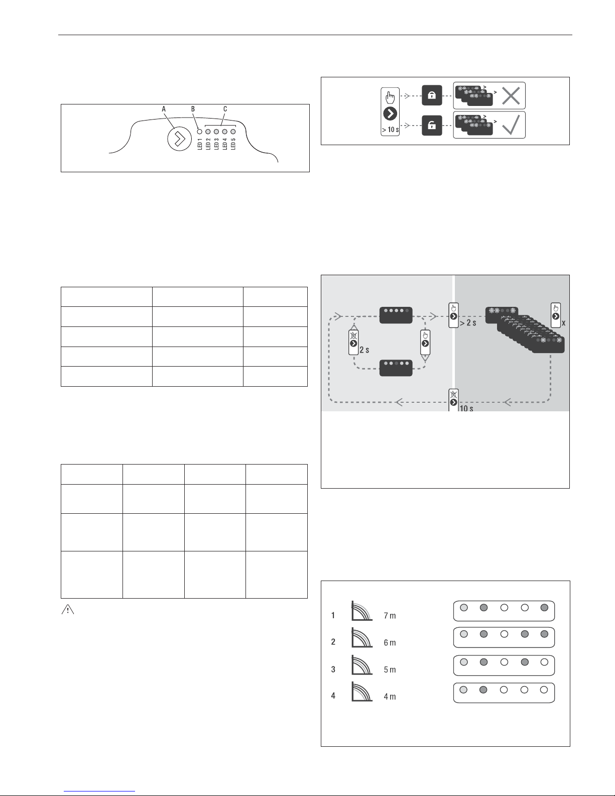
ENGLISH
16
Below the main characteristics and the ways to set up their desired
operation are listed.
User interface
The user interface is made up of a button (A), a two-coloured red /
green LED (B) and four yellow LEDs (C) arranged in a row.
The user interface allows the operating performance to be viewed
(operating status and alarm status) and it also allows the circulator
operating modes to be set.
The performance, indicated by the LEDs (B) and (C) is always visible
during normal operation of the circulator whereas the settings can be
carried out by pressing the button (A) .
Operating status indication
When the circulator is in operation the LED (B) is green. The four
yellow LEDs (C) indicate the electrical energy consumption (P1) as
shown in the following table
LED status CIRCULATOR status
Consumption in
% of MAX P1 (*)
Green LED on +
1 yellow LED on
Operating at minimum 0~25
Green LED on +
2 yellow LEDs on
Operating at
minimum-medium
25~50
Green LED on +
3 yellow LEDs on
Operating at medium-
maximum
50~75
Green LED on +
4 yellow LEDs on
Operating at maximum 100
(*) For the power (P1) absorbed by the circulator see the indications
in the “Technical Data” table.
Alarm status indication
If the circulator has detected one or more alarms the two-coloured
LED (B) will be red. The four yellow LEDs (C) indicate the type of
alarm as shown in the following table.
LED status
ALARM
description
Status
CIRCULATOR
Possible
SOLUTION
Red LED on +
1 yellow LED
on (LED 5)
The drive shaft
is jammed
Start attempt
every 1.5
seconds
Wait or unjam
the drive shaft
Red LED on +
1 yellow LED
on (LED 4)
Low input
voltage
Warning only.
The circulator
continues to
operate
Check the
input voltage
Red LED on +
1 yellow LED
on (LED 3)
Electrical power
supply fault or
faulty circulator
The circulator
is stopped
Check the
electrical
power supply
or replace the
circulator
If there are several alarms the circulator will display only the
alarm with the highest priority.
Display of active settings
With the circulator powered, press briefly on the button (A) to view
the active configuration of the circulator. The LEDs indicate the active
settings.
In this phase no variations can be made to the circulator configuration. Two seconds after the button (A) has been pressed the user
interface returns to the normal operating status display.
Key lock function
The purpose of the key lock function is to prevent accidental modifications to the settings or the improper use of the circulator.
When the key lock function is activated, long-pressing the button (A)
is prevented. This prevents the user from entering the circulator's
operating modes setting section.
Enabling/disabling the key lock function is achieved by pressing the
button (A) for more than 10 seconds. During this step all of the LEDs
(C) will flash for 1 second.
Changing the operating mode
In normal operating conditions the circulator works with the factory
settings or the last settings carried out.
To change the configuration:
Ensure that the key lock function is deactivated.
Press the button (A) for more than 2 seconds until the LEDs begin
to flash. Short-press the button (A) within 10 seconds and the user
interface will move on to display the next settings. The various available settings will appear in a cyclic sequence.
If the button (A) is not pressed, the last setting will be stored.
A
B
C
A. Operating status display
B. Settings display
C. Settings
Configuración
If the button (A) is pressed you can move back to the “active settings
display” again and check that the LEDs (B) and (C) indicate (for 2
seconds) the last setting carried out.
If the button (A) is not pressed for more than 2 seconds the user
interfaces switches to the “Operating status display”.
The available settings are shown in figure along with the related representation of LED (B) and (C).
(*)
LED 1RLED 2GLED 3GLED 4GLED 5
G
(*) Factory set value
R red
G yellow
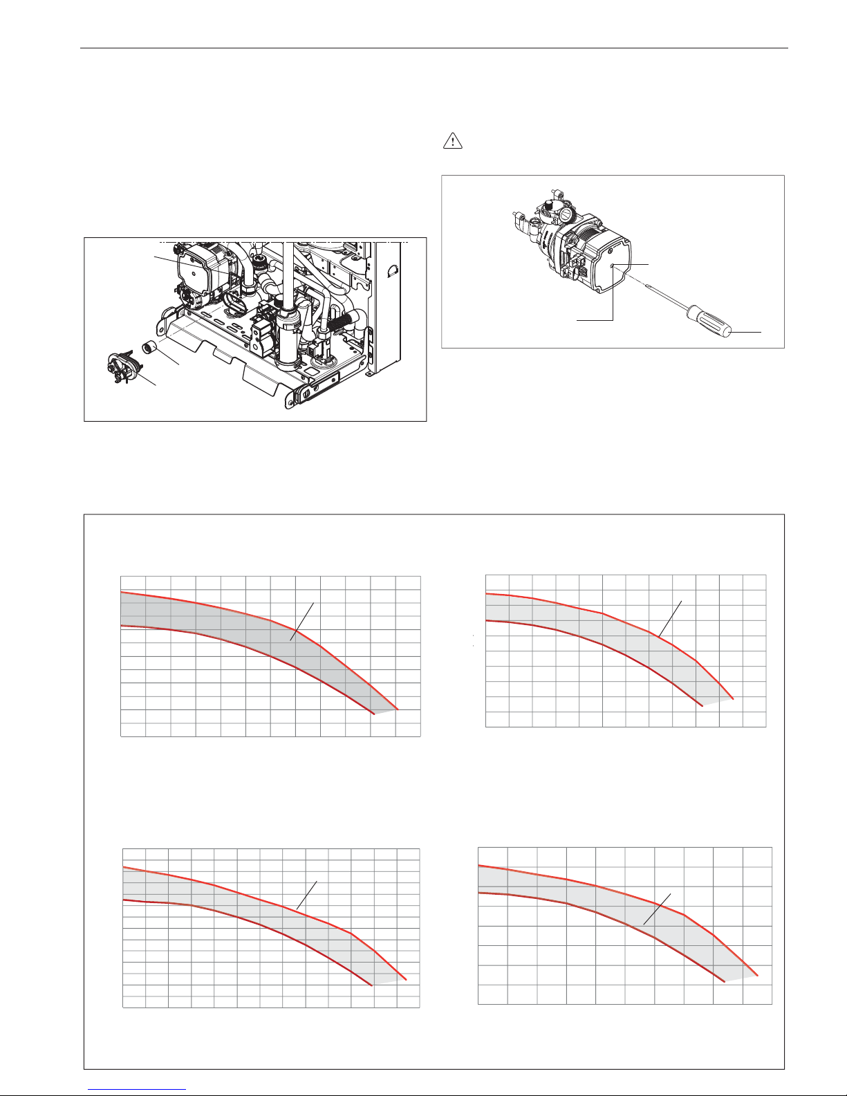
MySMART C.S.I.
17
IMPORTANT
If the 3 (5 metres) or 4 (4 metres) curves are set the bypass must
be replaced with the one supplied, following the procedure indicated
below:
Remove boiler electrical power by setting the system's main switch
to off.
Close the system taps and empty the boiler heating circuit.
Extract the bypass body cover fixing spring (D).
Extract the bypass body cover (E).
Replace the bypass valve (F) with the one included.
Refit the bypass body cover and its spring.
D
F
E
Eventual releasing of the circulator shaft
Insert a screwdriver in the hole (1) of the circulator
Press (a) and turn the screwdriver (b) until the release of the
crankshaft.
Perform this operation with extreme caution to avoid damag-
ing the components.
1
a
b
0
50
100
150
200
250
300
350
400
450
500
550
600
0 100 200 300 400 500 600 700 800 900 1000 1100 1200
Modulation area
Discharge head [mbar]
6 METRES DISCHARGE HEAD
System capacity [l/h]
0
50
100
150
200
250
300
350
400
450
500
550
600
650
700
0 100 200 300 400 500 600 700 800 900 1000 1100 1200 130
0
Modulation area
Discharge head [mbar]
7 METRES DISCHARGE HEAD
System capacity [l/h]
0
50
100
150
200
250
300
350
400
450
500
0 100 200 300 400 500 600 700 800 900 1000 1100 1200
[]
Modulation area
Discharge head [mbar]
5 METRES DISCHARGE HEAD
System capacity [l/h]
0
50
100
150
200
250
300
350
400
0 100 200 300 400 500 600 700 800 900 1000
4 METRES DISCHARGE HEAD
Modulation area
System capacity [l/h]
Discharge head [mbar]

ENGLISH
18
TECHNICAL DATA
DESCRIPTION MySMART 28 C.S.I.
G20 G31
Heating Nominal heat input kW
20,00
kcal/h
17.200
Nominal heat output (80/60°) kW
19,62
kcal/h
16.873
Nominal heat output (50°/30°) kW
21,44
kcal/h
18.438
Reduced heat input kW
2,80 4,00
kcal/h
2.408 3.440
Reduced heat output (80°/60°) kW
2,76 3,95
kcal/h
2.377 3.399
Reduced heat output (50°/30°) kW
3,00 4,20
kcal/h
2.577 3.609
Nominal Range Rated heat output (Qn)
kW
20,00
kcal/h
17.200
Minimum Range Rated heat output (Qm)
kW
6,00 4,00
kcal/h
5.160 3.440
Domestic hot water Nominal heat input kW
28,00
kcal/h
24.080
Nominal heat output (*) kW
28,00
kcal/h
24.080
Reduced heat input kW
2,80 4,00
kcal/h
2.408 3.440
Reduced heat output (*) kW
2,80 4,00
kcal/h
2.408 3.440
He
at/Domestic hot water Heat input at minimum with installation in smoke pipe
under pressure
kW
2,8 4,0
Useful efficiency Pn max - Pn min (80°/60°) %
98,1-98,7 98,4-98,8
Useful efficiency 30% (47° return) %
102,4 100,7
Combustion efficiency %
98,3
Useful efficiency Pn max - Pn min (50°/30°) %
107,2-107,0 104,6-104,9
Useful efficiency 30% (30° return) %
109,6 107,3
P Average Range Rated efficiency (80°/60°) % 98,4 Electric power W
94
Maximum circulator electric power (1.000 l/h) W
51
Category
II2H3P
Country of destination
(+)
Power supply voltage V - Hz
230-50
Protection level IP
X5D
Stop loss W
26
Nominal loss at smoke pipe with burner extinguished %
0,05
Nominal loss at smoke pipe with burner ignited %
1,68
Nominal loss at smoke pipe with burner ignited at minimum %
0,61
Nominal loss through the shell with burner ignited %
0,22
CH operation
Pressure - maximum temperature bar-°C 3-90
Minimum pressure for standard operation bar 0.25-0.45
Selection field of heating water temperature °C 20/45 ~ 40/80
Pump: maximum head available mbar 326
for system capacity l/h 1.000
Membrane expansion tank l 9
Expansion tank pre-charge bar 1
DHW operation
Maximum pressure bar 6
Minimum pressure bar 0.2
Hot water quantity with ∆t 25°C l/min 16,1
with ∆t 30°C l/min 13,4
with ∆t 35°C l/min 11,5
DHW minimum capacity l/min 2
Selection field of DHW temperature °C 37-60
Flow regulator l/min 11
(*) average value between various hot water operation conditions

MySMART C.S.I.
19
DESCRIPTION MySMART 28 C.S.I.
Gas pressure G20 G31
Nominal gas pressure mbar 20 37
Hydraulic connections
HC input - output Ø 3/4”
DHW input-output Ø 1/2”
Gas input Ø 3/4”
Boiler dimensions
Height mm 780
Height with hydraulic cover connection mm 845
Width mm 400
Depth at shell mm 358
Boiler weight kg 39
Heating capacity
G20 G31
Heating air flow Nm3/h
24,298 24,819
Heating gases flow Nm3/h
26,304 26,370
Max - min. heating mass flue gas flow rate gr/s
9,086-1,272 9,297-1,859
Domestic hot water capacity
G20 G31
Domestic hot water air flow Nm3/h
34,017 34,746
Domestic hot water gas flow Nm3/h
36,825 36,918
Max - min DHW mass flue gas flow rate gr/s
12,720-1,272 13,016-1,859
Fan performance
0.85 m concentric pipes residual discharge head Pa 50
0.5 m separated pipes residual discharge head Pa 70
Residual discharge head of boiler without pipes Pa 80
Concentric flue gas outlet pipes
Diameter mm 60-100
Maximum length m 7.8
Losses for a 45°/90° bend m 1.3/1.6
Hole in wall (diameter) mm 105
Concentric flue gas outlet pipes
Diameter mm 80-125
Maximum length m20
Losses for a 45°/90° bend m 1/1.5
Hole in wall (diameter) mm 130
Twin flue gas outlet pipes
Diameter mm 80
Maximum length m 50+50
Losses for a 45°/90° bend m 1/1.5
B23P-B53P Installation
Diameter mm 80
Maximum discharge length m 80
Collective smoke pipes under pressure (only with specific accessory)
Maximum allowed pressure in smoke pipe in the event
of installation with collective smoke pipe Pa 50 50
NOx class 5
Emission values at maximum and minimum gas flow rate (***) G20 G31
Maximum CO s.a. lower than ppm
150 190
CO
2
%
9,0 10,0
NOx s.a. lower than ppm
30 30
Temperature of the flue gases °C
67 67
Minimum CO s.a. lower than ppm
10 20
CO
2
%
9,0 10,0
NOx s.a. lower than ppm
25 35
Temperature of the flue gases °C
57 55
(***) Check performed with concentric pipe Ø 60-100, length 0.85 m - water temperature 80-60°C.
(+) The installation of this product is allowed only in the destination Countries contained in the data plate, regardless of the present translation language.
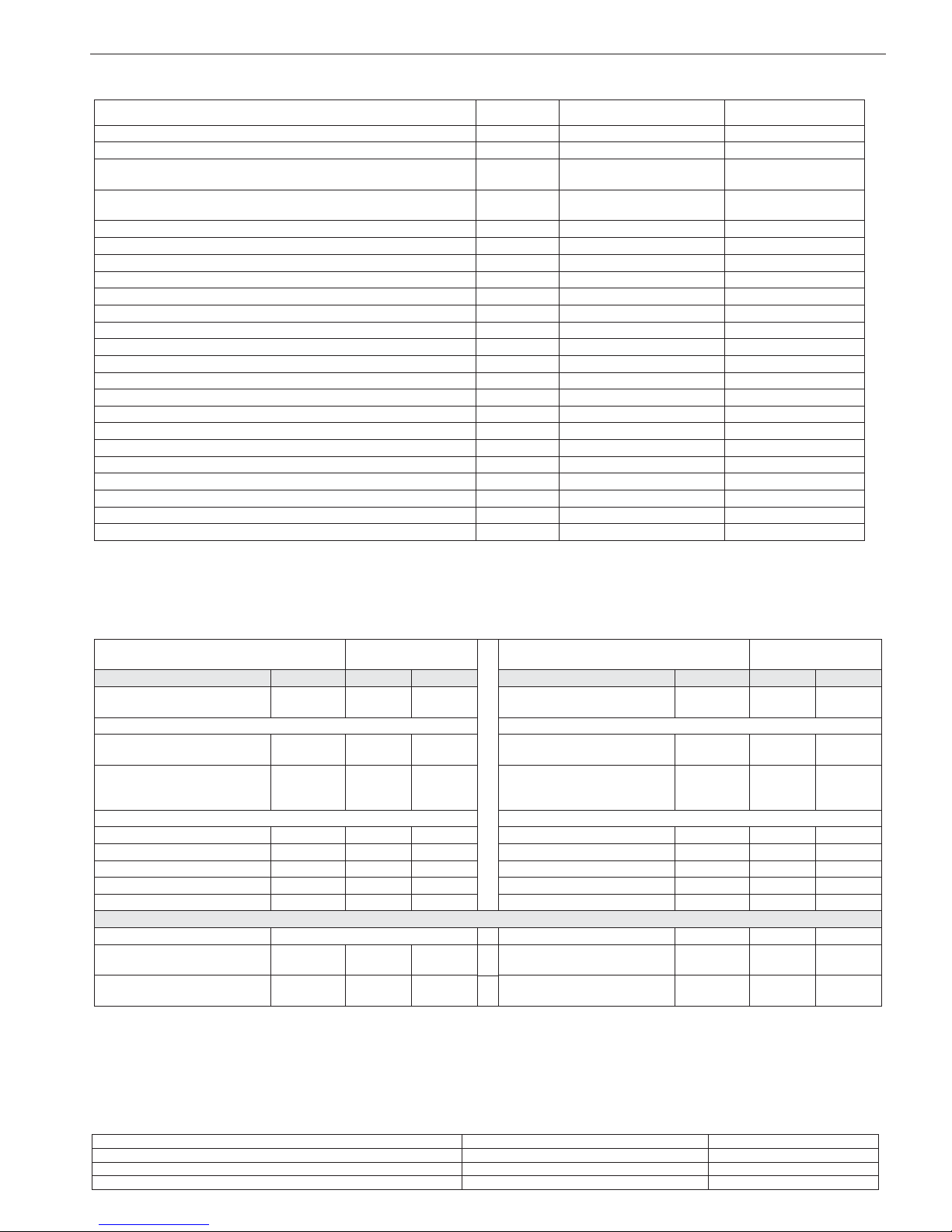
ENGLISH
20
NOTE (if the external probe or the control panel, or even both devices, are present in the boiler)
With reference to the Delegated Regulation (EU) No. 811/2013, the information in the table can be used for completing the product data sheet and the
labeling for room heating appliances, for mixed heating appliances, for all those appliances for enclosed space heating, for temperature control devices
and solar devices:
COMPONENT Class Bonus
EXTERNAL PROBE II 2%
CONTROL PANEL V3%
EXTERNAL PROBE + CONTROL PANEL VI 4%
MySMART 28 C.S.I.
Seasonal ambient heating
energy efficiency class
A Water heating energy efficiency class A
Parameter Symbol Value Unit Parameter Symbol Value Unit
Nominal output Pnominale 20 kW
Seasonal ambient heating
energy efficiency
ηs94%
For boilers for ambient heating and combined: Useful heat output For boilers for ambient heating and combined: efficiency
At nominal heat output and at
high temperature operation (*)
P4 19.6 kW
At nominal heat output and at
high temperature operation (*)
η4 88.6 %
At 30% of the nominal
heat output and at low
temperature operation (**)
P1 6.6 kW
At 30% of the nominal
heat output and at low
temperature operation (**)
η1 98,7 %
Auxiliaries electrical consumption Other parameters
At full load elmax 29,0 W Heat loss in standby mode Pstby 26,0 W
At partial load elmin 10.4 W Pilot flame energy consumption Pign - W
In Standby mode PSB 2.4 W Annual energy consumption QHE 39 GJ
Internal sound output level LWA 51 dB
Nitric oxide emissions NOx 29 mg/kWh
For combined heating appliances
Declared load profile XL Heating water energy efficiency ηwh 85 %
Daily electrical energy
consumption
Qelec 0,139 kWh Daily fuel consumption Qfuel 22,827 kWh
Annual electrical energy
consumption
AEC 30 kWh Annual fuel consumption AFC 17 GJ
(*) High temperature operation: 60°C at boiler return line and 80°C at boiler delivery line.
(**) Low temperature operation: For condensing boilers 30°C, for low temperature boilers 37°C, for other heating appliances 50°C return line
temperature.
MULTIGAS TABLE
DESCRIPTION
Methane gas
(G20)
Propane
(G31)
Lower Wobbe index (at 15°C-1013 mbar) MJ/m3S 45,67 70,69
Net Calorific Value MJ/m3S 34,02 88
Supply nominal pressure mbar
mm W.C.
20 (203,9) 37 (377,3)
Supply minimum pressure mbar
mm W.C.
10 (102,0) -
MySMART 28 C.S.I.
Diaphragm - number of holes No.
22
Diaphragm - diameter of holes ø mm
1x4,7 fl ap+1x4,2 free
1x3,4 fl ap+1x3,25 free
Burner diameter mm 63 63
Burner length mm 95 95
HC maximum gas capacity Sm3/h 2,12
kg/h 1,55
DHW maximum gas capacity Sm3/h 2,96
kg/h 2,17
HC minimum gas capacity Sm3/h 0,30
kg/h 0,31
DHW minimum gas capacity Sm
3
/h 0,30
kg/h 0,31
Number of fan rotations with slow ignition rpm 3.300 3.300
Maximum number of heating fan rotations rpm 4.500 4.500
Maximum domestic hot water fan rotations rpm 6.100 6.100
Minimum number of heating fan rotations rpm 1.200 1.500
Minimum number of DHW fan rotations rpm 1.200 1.500
Minimum number of fan rotations with collective pipes under pressure rpm 1.800 1.900
The data indicated must not be used to certify the system; for certification, use the data indicated in the “System handbook” measured during
first ignition.
All the pressure values are measured with the compensation socket disconnected.

MySMARTC.S.I.
21
ES
INSTALADOR
1 - ADVERTENCIAS Y SEGURIDAD
Las calderas producidas en nuestros establecimientos se fa-
brican prestando atención a cada uno de los componentes de
manera tal de proteger tanto al usuario como al instalador contra eventuales accidentes. Se aconseja al personal cualificado,
después de cada intervención efectuada en el producto, que
preste particular atención a las conexiones eléctricas, sobre
todo por lo que se refiere a la parte no cubierta de los conductores, que de ninguna forma tiene que sobresalir de la bornera,
evitando de esta forma el posible contacto con las partes vivas
de dicho conductor.
El presente manual de instrucciones, junto con el del usuario,
forma parte integrante del producto: hay que comprobar que
forme parte del equipamiento del aparato, incluso en el caso
de cesión a otro propietario o usuario, o bien de traslado a otra
planta. En caso de daño o extravío debe solicitarse otro ejemplar al Servicio Técnico de Asistencia de la zona.
La instalación de la caldera y cualquier otra intervención de
asistencia y de mantenimiento deben ser realizadas por personal cualificado según las indicaciones de las normas en vigor
y en conformidad con las normas UNI 7129-7131, UNI 11071 y
sus actualizaciones.
Efectuar el mantenimiento de la caldera por lo menos una vez
al año, programándolo anteriormente con el Servicio de Asistencia Técnica.
Se aconseja al instalador que instruya al usuario sobre el fun-
cionamiento del aparato y sobre las normas fundamentales de
seguridad.
Esta caldera debe destinarse al uso para el cual ha sido ex-
presamente fabricada. Se excluye cualquier responsabilidad
contractual y extracontractual del fabricante por daños causados a personas, animales o cosas, por errores de instalación,
regulación, mantenimiento y por usos inadecuados.
Después de haber quitado el embalaje, se debe comprobar
que el contenido esté íntegro y completo. En el caso de que no
exista correspondencia, ponerse en contacto con el revendedor donde se ha adquirido el aparato.
El colector de los conductos de evacuación del aparato debe
estar conectado a un sistema de evacuación adecuado. El
fabricante del aparato no se responsabiliza por eventuales
daños o derrames causados por la ausencia del sistema de
canalización.
Eliminar los elementos de embalaje en los contenedores ade-
cuados en los centros de recogida específicos.
Los residuos deben eliminarse sin causar peligro a la salud del
hombre y sin utilizar procedimientos o métodos que pudieran
producir daños al medio ambiente.
El producto, al finalizar su vida útil, no se debe eliminar como
un residuo sólido urbano, sino que se debe enviar a un centro
de recogida diferenciada.
Durante la instalación, se debe informar al usuario que:
- en caso de pérdidas de agua, se debe cerrar la alimentación
hídrica y avisar inmediatamente al Servicio de Asistencia
Técnica
- debe verificar periódicamente que la presión de funcionamiento de la instalación eléctrica sea superior a 1 bar. Si
fuese necesario, restablecer la presión como se indica en el
apartado "Llenado de la instalación"
- si está previsto que la caldera no se utilice durante un largo
periodo, se recomienda la intervención del Servicio de Asistencia Técnica para realizar al menos las siguientes operaciones:
- colocar el interruptor principal del aparato y el general de
la instalación en “Apagado”
- cerrar los grifos del combustible y del agua de la instalación térmica
- vaciar la instalación térmica si existiese riesgo de congelación.
Desde el punto de vista de la seguridad se debe recordar que:
se desaconseja el uso de la caldera por parte de niños o de
personas incapacitadas no asistidas
es peligroso accionar dispositivos o aparatos eléctricos como
interruptores, electrodomésticos, etc., si se percibe olor a combustible o a combustión. En el caso de pérdidas de gas, airear
el local abriendo puertas y ventanas; cerrar el grifo general del
gas; solicitar la inmediata intervención de personal profesionalmente cualificado del Servicio de Asistencia Técnica
no tocar la caldera estando descalzo o con partes del cuerpo
mojadas o húmedas
colocar el selector de función en la posición OFF/RESET hasta
visualizar “- -” en la pantalla y desconectar la caldera de la red
de alimentación eléctrica, colocando el interruptor bipolar de
la instalación en "Apagado" antes de realizar operaciones de
limpieza
está prohibido modificar los dispositivos de seguridad o de re-
gulación sin la autorización o las indicaciones del fabricante
no tirar, separar, torcer los cables eléctricos que sobresalen de
la caldera aunque esté desconectada de la red de alimentación eléctrica
evitar tapar o reducir las dimensiones de las aberturas de ven-
tilación del local de instalación
no dejar contenedores ni sustancias inflamables en el local
donde está instalado el aparato
no dejar los elementos del embalaje al alcance de los niños
está prohibido cerrar la descarga de la condensación.
2 - DESCRIPCIÓN
MySMART C.S.I. es una caldera mural de condensación de tipo C
para el calentamiento y la producción de agua sanitaria caliente: según el accesorio de evacuación de los humos utilizado, se clasifica
en las siguientes categorías: B23P; B53P; C13,C13x; C33, C33x;
C43,C43x; C53,C53x; C63, C63x; C83,C83x; C93, C93x, 3CEP
En la configuración B23P (cuando se instala en el interior) el aparato
no puede ser instalado en locales destinados a dormitorios, baños,
duchas o en donde existan chimeneas abiertas sin aflujo de aire
propio. El local donde se instalará la caldera deberá tener una ventilación adecuada. Las prescripciones detalladas para la instalación
de la chimenea, de las tuberías del gas y para la ventilación del local
están contenidas en las normas UNI 7129-7131 y UNI 11071.
En la configuración C , el aparato puede ser instalado en cualquier
tipo de local sin limitación alguna respecto de las condiciones de
ventilación y volumen del mismo.
También es posible, mediante un clapet suministrado como accesorio, instalar la caldera en conductos colectivos bajo presión; consultar los detalles en el apartado 3.12 “Instalación en chimeneas colectivas con presión positiva”.
3 - INSTALACIÓN
3.1 Normas de instalación
La instalación debe ser realizada por el personal cualificado requerido por las normativas locales.
UBICACIÓN
MySMART C.S.I. es una caldera mural para el calentamiento y la
producción de agua caliente que, según el tipo de instalación, se
identifica en dos categorías:
1. Caldera de tipo B23P-B53P, instalación forzada abierta, con
conducto de evacuación del humo y toma de aire comburente
del ambiente en el cual está instalada. Si la caldera no está ins-
 Loading...