

Beretta Mynute Green E C.S.I., Mynute Green E R.S.I. Installer And User Manual
Mynute Green E C.S.I. R.S.I.
Installer and user manual
EN
FR
ES
PT
HU
RO
DE
SL
INSTALLER AND USER MANUAL
MANUEL D’INSTALLATION ET D’UTILISATION
MANUAL DE INSTALACIÓN Y USO
MANUAL PARA INSTALAÇÃO E USO
MANUAL DE INSTALARE SI UTILIZARE
HANDBUCH FÜR DIE MONTAGE UND BENUTZUNG
NAVODILA ZA VGRADITEV, PRIKLJUČITEV IN UPORABO
TELEPÍTŐI ÉS FELHASZNÁLÓI KÉZIKÖNYV
EN
MYNUTE GREEN E boiler complies with basic requirements of
the following Directives: Gas directive 2009/142/EC; Yield directive
92/42/EEC; Electromagnetic compatibility directive 2004/108/EC;
Low-voltage directive 2006/95/EC; Directive 2009/125/EC Ecodesign for energy-using appliances; Directive 2010/30/EU Indication
by labelling of the consumption of energy by energy-related products; Delegated Regulation (EU) No. 811/2013; Delegated Regulation (EU) No. 813/2013; Delegated Regulation (EU) No. 814/2013
(only for combi models).
EN
Installer’s-user’s manual 5
Boiler operating elements 167
Hydraulic circuit 171
Electric diagrams 178
Circulator residual head 184
HU
Az MYNUTE GREEN E kazán teljesíti az alábbi irányelvek lényegi
követelményeit: 2009/142/EK gáz irányelv; 92/42/EGK irányelv a
vízmelegítő kazánokról; 2004/108/EK irányelv az elektromágneses összeférhetőségről; 2006/95/EK irányelv a kisfeszültségű
berendezésekről; 2009/125/EK irányelv az energiafelhasználó termékek
környezetbarát tervezéséről; 2010/30/EU irányelv az energiával kapcsolatos termékek energia-fogyasztásának címkézéssel történő jelöléséről;
811/2013/EU felhatalmazáson alapuló rendelet; 813/2013/EU felhatalmazáson alapuló rendelet; 814/2013/EU felhatalmazáson alapuló
rendelet (csak kombinált típusokhoz).
HU
Telepítői-felhasználói kézikönyv 85
A kazán funkcionális alkatrészei 167
Hidraulikus kör 171
Elektromos rajzok 178
A keringetőszivattyú maradék emelőnyomása 184
FR
La chaudière MYNUTE GREEN E especte les conditions de
base requises par les Règlements suivants: Directive sur le gaz
2009/142/CEE; Directive sur le rendement 92/42/CEE; Directive
sur la compatibilité électromagnétique 2004/108/CEE; Directive
sur la basse tension 2006/95/CEE; Directive 2009/125/EC concernant les exigences d’écoconception applicables aux dispositifs
d’énergie; Directive 2010/30/EU concernant l’étiquetage des consommations d’énergie des produits liés à l’énergie; Règlement Délégué (UE) No. 811/2013; Règlement Délégué (UE) N°. 813/2013;
Règlement Délégué (UE) N°. 814/2013 (uniquement pour les
modèles combinés).
FR
Manuel de l'utilisateur- de l'installateur 25
Éléments de fonctionnement de la chaudière 167
Circuit hydraulique 171
Schémas électriques 178
Hauteur de charge résiduelle 184
ES
La caldera MYNUTE GREEN E cumple con los requisitos básicos
de las siguientes Directivas: Directiva Gas 2009/142/CE; Directiva
rendimiento 92/42/CEE; Directiva compatibilidad electromagné-
tica 2004/108/CE; Directiva baja tensión 2006/95/CE; Directiva
2009/125/CE Diseño ecológico para aparatos que consumen energía; Directiva 2010/30/UE Indicación mediante etiquetado del
consumo energético de productos relacionados con la energía;
Reglamento Delegado (UE) N.º 811/2013; Reglamento Delegado
(UE) N.º 813/2013; Reglamento Delegado (UE) N.º 814/2013 (solo
para modelos combinados).
ES
Manual de usuario del instalador 45
Elementos de operación de la caldera 167
Circuito hidráulico 171
Diagramas eléctricos 178
Prevalencia residual del circulador 184
PT
A caldeira MYNUTE GREEN E é compatível com as especicações
básicas das seguintes Diretivas: Diretiva de gás 2009/142/CEE; Diretiva de rendimento 92/42/CEE; Diretiva de compatibilidade eletromagnética 2004/108/CE; Diretiva de baixa tensão 2006/95/CE; Diretiva
2009/125/CE concepção ecológica dos aparelhos que consomem
energia; Diretiva 2010/30/UE Indicação por meio de etiquetagem do
consumo energético pelos produtos relacionados com energia; Regulamento Delegado (UE) n.º 811/2013; Regulamento Delegado (UE)
n.º 813/2013; Regulamento Delegado (UE) n.º 814/2013 (apenas
para os modelos combinados).
PT
Manual do usuário-instalador 65
Elementos de operação da caldeira 167
Circuito hidráulico 171
Diagramas eléctricos 178
Cabeçal residual do circulador 184
RO
Centrala MYNUTE GREEN E este fabricată în conformitate
cu cerințele următoarelor Directive: Directiva gaz 2009/142/
EEC; Directiva eciență 92/42/EEC; Directiva compatibilitate
electromagnetică 2004/108/EEC; Directiva voltaj redus 2006/95/
EEC; Directiva 2009/125/CE în ceea ce privește cerințele de proiectare ecologică pentru aparatele consumatoare de energie; Direc-
tiva 2010/30/UE privind indicarea prin etichetare a consumului de
energie de către produsele cu impact energetic; Regulamentul Delegat (UE) Nr. 811/2013; Regulamentul Delegat (UE) Nr. 813/2013;
Regulamentul Delegat (UE) Nr. 814/2013 (doar pentru module
combinate).
RO
Manual de instalare - utilizare 105
Elementele funcţionale ale centralei 167
Circuit hidraulic 171
Scheme electrice 178
Cap rezidual pompă de circulaţie 184
DE
Der Heizkessel MYNUTE GREEN E erfüllt die grundlegenden
Anforderungen der folgenden Richtlinien: Gasgeräterichtlinie
2009/142/EG; Heizkessel-Wirkungsgradrichtlinie 92/42/EWG;
EMV-Richtlinie 2004/108/EG; Niederspannungsrichtlinie 2006/95/
EG; Ökodesign-Richtlinie 2009/125/EG für energieverbrauchsrelevante Produkte; Richtlinie 2010/30/EU über die Energieverbr-
auchskennzeichnung energieverbrauchsrelevanter Produkte; Delegierte Verordnung (EU) Nr. 811/2013; Delegierte Verordnung (EU)
Nr. 813/2013; Delegierte Verordnung (EU) Nr. 814/2013 (nur für
kombinierte Modelle).
DE
Installations- und Bedienungsanleitung 125
Elemente für den Kesselbetrieb 167
Wasserkreis 171
Schaltpläne 178
Restförderhöhe der Umlaufpumpe 184
SL
Kotol MYNUTE GREEN E je v zhode so základnými požiadavkami
nasledovných Smerníc: Smernica 2009/142/ES o plynových
spotrebičoch; Smernica 92/42/EHS o výťažnosti; Smernica
2004/108/ES o elektromagnetickej kompatibilite; Smernica 2006/95/
ES o nízkom napätí; Smernica 2009/125/ES o ekodizajne zariadení
používajúcich elektrickú energiu; Smernica 2010/30/EÚ o udávaní
energie výrobkov súvisiacich s energiou prostredníctvom štítkov;
Delegované nariadenie (EÚ) č. 811/2013; Delegované nariadenie
(EÚ) č. 813/2013; Delegované nariadenie (EÚ) č. 814/2013 (len pre
kombinované modely).
SL
Priročnik za montažo-uporabo 145
Elementi delovanja kotla 167
Hidravlični sistem 171
Sheme električnih povezav 178
Preostala višina črpanja 184
0694BU1240

EN
HU
This handbook contains data and information for both
users and installers. In detail:
• The chapters entitled “Installing the boiler, Water connections, Gas connection, Electrical connection, Filling and
draining, Evacuating products of combustion, Technical
data, Programming parameters, Gas regulation and con-
version” are intended for installers;
• The chapters entitled “Warnings and safety devices,
Switching on and using” are for both users and installers.
Ez a kézikönyv mind a felhasználók, mind pedig a fel-
szerelést végzők részére tartalmaz információkat és
adatokat. A részleteket illetően:
• Az “A kazán telepítése, Vízcsatlakozások, Gázcsatlakozás, Elektromos csatlakozás, Feltöltés és leeresztés,
Égéstermékek elvezetése, Műszaki adatok, Programozási paraméterek, Gázbeállítás és átállítás” fejezetek a felszerelést végző személyeknek szólnak;
• A “Figyelmezetetések és biztonsági berendezések,
Bekapcsolásuk és használatuk” c. fejezetek mind a fel-
használók, mind pedig a felszerelést végző szakembereknek szólnak.
RANGE RATED
This boiler can be adapted to the thermal requirements of the sys-
tem; it is possible, in fact, to set the maximum boiler delivery for
operation in heat mode. Refer to the “Adjustments” chapter for the
calibration settings.
Once the desired output has been set (maximum heating) transfer
the value into the table given on the back cover.
For subsequent checks and adjustments, always refer to the set
value.
RANGE RATED
Ezt a kazánt hozzá lehet igazítani a rendszer hőkövetelményeihez;
be lehet állítani ugyanis a maximális kazán előremenő vizet a fűtési
módban való üzemeléshez. A beállításhoz olvassa el a “Beállítá-
sok” fejezetet.
Mikor beállította a kívánt kimenetet (maximális fűtés), vigye át az
értéket a hátsó borítón megadott táblázatba.
A további ellenőrzések és beállítások alkalmával ezt a beállított értéket kell gyelembe venni.
FR
Ce manuel contient des données et des informations
pour les utilisateurs et pour les installateurs. Plus
spéciquement:
• Les chapitres intitulés "Installation de la chaudière",
"Raccords d'eau", "Raccord du gaz", "Branchements
électriques", "Remplissage et vidange", "Évacuation
des produits de la combustion", "Données techniques",
"Paramètres de programmation", "Réglage et conversion
du gaz" sont destinés aux installateurs.
• Les chapitres intitulés "Avertissements et dispositifs de
sécurité" et "Mise en marche et utilisation" sont destinés
aux utilisateurs et aux installateurs.
RANGE RATED
Cette chaudière peut être adaptée aux exigences thermiques du
système. En effet, il est possible de régler la puissance maximale de
la chaudière pour le fonctionnement en mode Chauffage. Se référer
au chapitre "Réglages" pour consulter les paramètres de réglage.
Une fois que la puissance a été réglée (paramètre de chauffage
maximum), transférer la valeur dans le tableau présent sur le couvercle arrière.
Pour les contrôles et les réglages ultérieurs, se référer à cette valeur.
ES
Este manual contiene datos e información tanto para
los usuarios como para los instaladores. En detalle:
• Los capítulos titulados “Instalación de la caldera, Conexiones de agua, Conexión de gas, Conexión eléctrica, Carga y vaciado, Evacuación de productos de combustión,
Datos técnicos, Programación parámetros, Regulación y
conversión de gas” contienen información para los insta-
ladores;
• Los capítulos titulados “Advertencias y dispositivos de
seguridad, Encendido y uso” son tanto para los usuarios
como para los instaladores.
RANGE RATED
Esta caldera se puede adaptar a los requisitos térmicos de la in-
stalación; es posible congurar el caudal máximo de la caldera
para el funcionamiento en modo calefacción. Consultar el capítulo
“Regulaciones” para congurar los valores.
Una vez congurada la potencia (térmica máxima), observar el
valor en la tabla de la chapa trasera.
Para controles y regulaciones posteriores, consultar el valor congurado.
PT
Este manual contém dados e informações tanto para
usuários quanto para instaladores. Em detalhes:
• Os capítulos intitulados “Instalação da caldeira, Conexões
de água, Conexão de gás, Conexão eléctrica, Enchimento e drenagem, Evacuação de produtos de combustão,
Dados técnicos, Parâmetros de programação, Regulação
e conversão do gás” são para uso dos instaladores;
• Os capítulos intitulados “Advertências e dispositivos de
segurança, Activação e uso” são para uso de usuários e
instaladores.
RANGE RATED
Esta caldeira pode ser adaptada às especicações térmicas do
sistema; é possível de facto, estabelecer o caudal máximo da cal-
deira para funcionamento em modo de aquecimento. Consultar o
capítulo “Regulações” para a calibragem.
Uma vez que a potência desejada tenha sido programada (aqueci-
mento máximo), transra o valor para a tabela dada na capa traseira.
Para controlos e regulações subsequentes, consultar portanto o
valor congurado.
RO
Acest manual conţine date şi informaţii atât pentru uti-
lizatori, cât şi pentru instalatori. Detaliat:
• Capitolele intitulate „Instalarea centralei, Conexiunile de
apă, Conexiunea de gaz, Conexiunea electrică, Umplerea
şi golirea, Evacuarea produselor de ardere, Date tehnice,
Programarea parametrilor, Reglarea şi conversia gazelor
sunt destinate instalatorilor”;
• Capitolele intitulate „Avertismente şi dispozitive de
siguranţă, Pornire şi utilizare sunt destinate atât utilizatorilor, cât şi instalatorilor”.
RANGE RATED
Centrala poate adaptată cererilor de căldură ale instalaţiei; este
posibil, de altfel, să setaţi puterea maximă de pe turul centralei
pentru funcţionarea în modul încălzire. Pentru operaţiunile de
reglare, faceţi referire la capitolul “Reglaje”.
Odată ce aţi setat puterea necesară (maxim încălzire), indicaţi
valoarea pe coperta de la sfârşitul manualului.
Pentru vericări și reglaje ulterioare, faceți întotdeauna referire la
valoarea setată.

DE
Dieses Handbuch enthält Daten und Informationen
sowohl für den Bediener als auch für den Installateur.
Im Einzelnen:
• Die Kapitel mit den Überschriften “Installation des Kessels, Wasseranschlüsse, Gasanschluss, Elektrische Anschlüsse, Befüllen und Entleeren, Ableiten der Verbrennungsprodukte, Technische Daten, Programmieren der
Parameter, Gaseinstellung und Umrüstung" richten sich
an Installateure;
• Die Kapitel mit den Überschriften “Hinweise und Sicherheitsvorrichtungen, Einschalten und Gebrauch” richten
sich sowohl an Anwender als auch an Installateure.
RANGE RATED
Dieser Kessel lässt sich an die Wärmeerfordernisse der Anlage
anpassen; man kann nämlich die höchste Kesselleistung für Heizbetrieb einstellen. Für die Einstellung wird auf das Kapitel "Einstellungen" verwiesen.
Nach dem Einstellen der gewünschten Leistung (maximale Heizleistung) übertragen Sie den Wert in die Tabelle auf der hinteren
Abdeckung.
Für nachfolgende Kontrollen und Einstellungen beziehen Sie sich
immer auf den Sollwert.
SL
Ta priročnik vsebuje podatke in informacije tako za
uporabnika kot tudi za instalaterja. Podrobneje:
• Poglavja z naslovom “Montaža kotla, Priklop plina, Priklop
elektrike, Polnjenje in praznjenje, Odvajanje produktov zgorevanja, Tehnični podatki, Programiranje parametrov, Regu-
lacija in sprememba plina” so namenjena instalaterjem;
• Poglavja z naslovom “Opozorila in varnostne napravee,
Vklop in uporaba” so namenjena uporabnikom in instalaterjem.
RANGE RATED
Ta kotel se lahko prilagaja toplotnim zahtevam sistema; dejansko
se lahko nastavi največjo toplotno moč kotla za delovanje ogrevanja. O umerjanju kotla glejte poglavje “Nastavitve”.
Ko je želena izhodna moč nastavljena (največja moč ogrevanja),
vnesite vrednost v tabelo, ke se nahaja na zadnji strani pokrova.
Za nadaljnje kontrole in prilagoditve vedno glejte nastavljeno vrednost.
ENGLISH
5
1 - GENERAL SAFETY DEVICES
Our boilers are built in our plants and checked down to the
smallest detail in order to protect users and tters from injury.
After working on the product, qualied personnel must check
the electrical wiring, in particular the stripped part of conductors, which must not stick out from the terminal board, avoid-
ing possible contact with live parts of such conductor.
This instruction manual is integral parts of the product: make
sure that it remains with the appliance, even if it is transferred
to another owner or user, or moved to another heating system. In case of loss or damage, please contact your local
Technical Assistance Service for a new copy.
Boiler installation and any other assistance and maintenance
operation must be carried out by qualied personnel according to current local and national regulations.
The installer must instruct the user about the operation of the
appliance and about essential safety regulations.
This boiler may only be used for what it was expressly built to
do. The manufacturer declines all contractual and non-contractual liability for injury to persons or animals or damage to
property deriving from errors made during installation, adjustment and servicing and from improper use.
This appliance is used to produce hot water and must there-
fore be connected to a heating and/or a domestic hot water
system, according to its performance and power.
After removing the packaging, make sure the contents are
undamaged and complete. If this is not the case, contact your
dealer.
The safety and automatic adjustment devices on the appli-
ance must never be modied during its lifetime, except by the
maker or dealer.
If the appliance develops a fault and/or works badly, switch it
off and do not attempt to repair it yourself.
When the product reaches the end of its life it should not be
disposed of as solid urban waste but should be brought to a
separated waste collection facility.
The safety valve outlet must be connected to a suitable col-
lection and venting system. The manufacturer declines all liability for any damage caused due to any intervention carried
out in the safety valve.
Dispose of all the packaging materials in the suitable contain-
ers at the corresponding collection centres.
Dispose of waste being careful not harm human health and
without employing procedures or methods which may damage the environment.
Connect the outlet collector to a suitable outlet system (refer
to chapter 3.5).
During installation, inform the user that:
• in the event of leaks, he/she must shut off the water supply and
promptly inform the Technical Assistance Service
• the operating pressure of the system ranges between 1 and 2 bar
and must never be greater than 3 bar. If necessary, reset the pres-
sure as indicated in the paragraph entitled “Filling the system”
• if the boiler is not planned to be used for a long period, he/she
should call in the Technical Assistance Service to perform the
following operations:
- turn off the main boiler and general system switches
- close the gas and water taps on both the heating (C.S.I. R.S.I.) and domestic hot water circuits (C.S.I.)
- drain the heating (C.S.I. - R.S.I.) and domestic hot water
(C.S.I.) circuits to prevent freezing.
Safety measures:
The boiler should not be used by children or unassisted dis-
abled people.
Electrical devices or equipment, such as switches, applianc-
es, etc., should not be used if there is a smell of gas or fumes.
If there is a gas leak, open all the doors and windows to ventilate the area, turn off the general gas tap and immediately
call the Technical Assistance Service.
Do not touch the boiler barefoot or if parts of your body are
wet or damp.
Before cleaning operations, disconnect the boiler from the
main power supply by turning “OFF” the two position system
switch and the main control panel switch.
It is forbidden to modify the safety or adjustment devices with-
out the manufacturer’s permission and relative instructions.
Do not pull, detach or twist the wires from the boiler even if
they are not connected to the power supply.
Do not block or reduce the size of the ventilation openings in
the room.
Do not leave inammable containers or substances in the
room.
Keep packaging out of reach of children.
It is forbidden to block the condensate outlet.
2 - BOILER INSTALLATION
Boiler must only be installed by qualied personnel in compliance
with current legislation.
Mynute Green E is available in the following models:
Mynute Green C.S.I. E are type C wall-mounted condensation
boilers for heating and the production of domestic hot water.
Mynute Green R.S.I. E are type C wall-mounted condensation
boilers capable of operating in different conditions through a series
of jumpers tted on the electronic board (consult the “Boiler conguration” section):
CASE A: only heating. The boiler does not provide domestic hot
water.
CASE B: only heating with an external thermostat-controlled water
tank: in this condition, the boiler delivers hot water to the water tank
whenever a demand is made by the relative thermostat.
CASE C: only heating with an external temperature probe-con-
trolled water tank (accessory kit available on request), for the
production of hot water. If the water tank is not supplied by our
company, make sure that the relative NTC probe has the following
characteristics: 10 kOhm at 25°C, B 3435 ±1%.
According to the ue gas outlet device, the boilers are classied in
categories B23P, B53P, C13, C23, C33, C43, C53, C63, C83, C93,
C13x, C33x, C43x, C53x, C63x, C83x, C93x.
In conguration B23P and B53P (when installed indoors), the appliance cannot be installed in bedrooms, bathrooms, showers or
where there are open replaces without a proper air ow. The room
where the boiler is installed must have proper ventilation.
In conguration C, the appliance can be installed in any type of
room and there are no limitations due to ventilation conditions or
room volume.
3 - INSTALLATION REGULATIONS
3.1 Installation regulations
Installation must be carried out by qualied personnel.
Always comply with national and local regulations.
Mynute Green E can be installed indoors.
The boiler has protection that guarantees correct operation with a
temperature range from 0°C to 60°C.
The following symbols are used in this manual:
CAUTION = operations requiring special care and adequate preparation
NOT ALLOWED = operations that MUST NOT de performed
R.S.I: DHW functions refer only if a water thank is connected (accessory
available on request).
INSTALLER
EN

Mynute Green C.S.I. E - R.S.I. E
6
To take advantage of protections, the appliance must be able to
start up, since any lockout condition (for example, absence of gas
or electrical supply, or safety intervention) deactivates the protec-
tions.
MINIMUM DISTANCES
In order to have access to the boiler to perform regular mainte-
nance operations, respect the minimum spaces foreseen for installation (g. 1a).
For correct appliance positioning:
- do not place it on a cooker or other cooking device
- do not leave inammable products in the room where the boiler
is installed
- heat sensitive walls (for example, wooden walls) must be protected with proper insulation.
IMPORTANT
Before installation, wash every system piping carefully in order to
remove any residues that may impair the operation of the appliance.
Under the safety valve, install a water collecting funnel with the
corresponding discharge in the event of leaks due to the overpressure of the heating system. The domestic hot water circuit does
not need a safety valve, but make sure that the pressure of waterworks does not exceed 6 bar. In case of doubts, install a pressure
reducer.
Prior to ignition, make sure that the boiler is designed to operate
with the gas available; this can be checked by the message on the
packaging and the adhesive label indicating the gas type.
It is very important to highlight that in some cases the smoke pipes
are under pressure and therefore, the connections of several elements must be airtight.
ANTI-FREEZE SYSTEM
The boiler is tted as standard with an automatic anti-freeze system that activates when the temperature of the water in the primary
circuit falls below 0 °C. This system is always active, guaranteeing
boiler protection to an outdoor temperature level of -3 °C. To take
advantage of this protection (based on burner operation), the boiler
must be able to switch itself on; any lockout condition (e.g. lack
of gas/electricity supply, or safety device intervention) therefore
deactivates the protection. The anti-freeze protection is also ac-
tive when the boiler is on standby. In normal operation conditions,
the boiler can protect itself against freezing. If the machine is left
unpowered for long periods in areas where temperatures may fall
below 0 °C, and you do not want to drain the heating system, you
are advised to add a specic, good quality anti-freeze liquid to the
primary circuit. Carefully follow the manufacturer’s instructions with
regards not only the percentage of anti-freeze liquid to be used for
the minimum temperature at which you want to keep the machine
circuit, but also the duration and disposal of the liquid itself.
For the domestic hot water part, we recommend you drain the cir-
cuit. The boiler component materials are resistant to ethylene glycol based anti-freeze liquids.
3.2 Cleaning the system and characteristics of the
heating circuit water
In the case of a new installation or replacement of the boiler, it is
necessary to clean the heating system.
To ensure the device works well, top up the additives and/or chemical treatments (e.g. antifreeze liquids, lming agents, etc.) and
check the parameters in the table are within the values indicated.
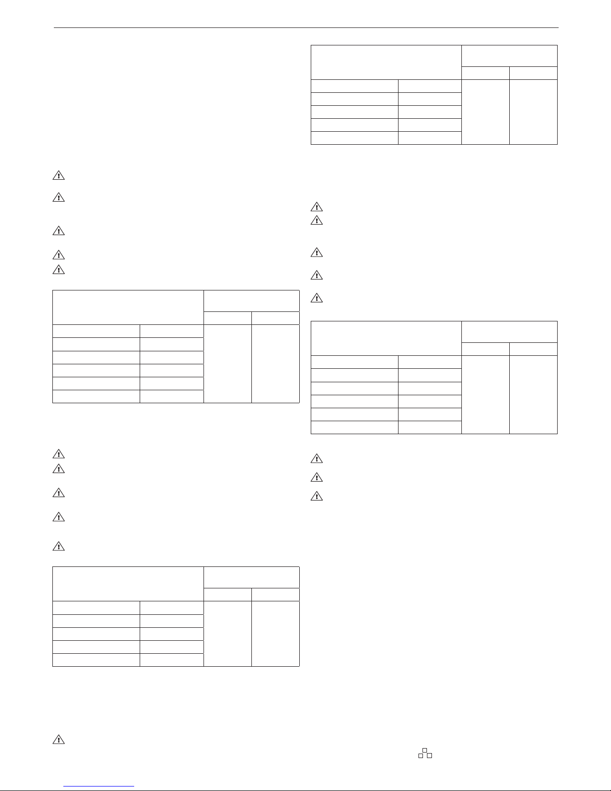
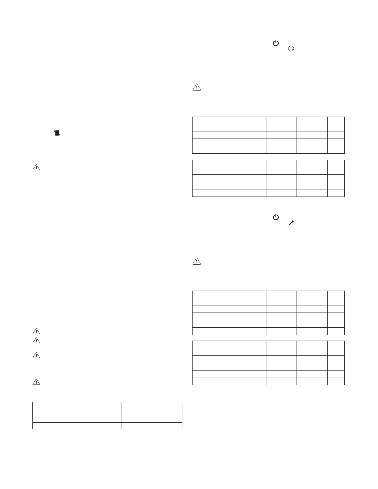
Parameters
Unit of
measurement
Hot water
circuit
Filling water
pH value 7–8 -
Hardness °F - 15–20
Appearance - clear
3.3 Securing the boiler to the wall and hydraulic connections
To fasten the boiler to the wall, use the crossbar (g. 3) in the packaging. The position and size of the hydraulic connections are indicated below:
A CH return 3/4”
B CH delivery 3/4”
C gas connection 3/4”
D DHW output 1/2” (C.S.I.) - 3/4” (R.S.I.)
E DHW input 1/2” (C.S.I.) - 3/4” (R.S.I.)
If water hardness exceeds 28°Fr, it is recommended to use water
softeners, to prevent any limestone deposit in boiler due to exces-
sively hard water.
3.4 Installation of the external sensor (g. 2)
The correct operation of the external sensor is fundamental for the
good operation of the climate control.
INSTALLING AND CONNECTING THE EXTERNAL SENSOR
The sensor must be installed on an external wall of the building to
be heated, observing the following indications:
it must be mounted on the side of the building most often exposed
to winds (the NORTH or NORTHWEST facing wall), avoiding direct
sunlight; it must be mounted about two thirds of the way up the wall;
it must not be mounted near doors, windows or air outlet points,
and must be kept away from smoke pipes or other heat sources.
The electrical wiring to the external sensor is made with a bipolar
cable with a section from 0.5 to 1 mm2 (not supplied), with a maximum length of 30 metres. It is not necessary to respect the polarity
of the cable when connecting it to the external sensor. Avoid making any joints on this cable however; if joints are absolutely neces-
sary, they must be watertight and well protected. Any ducting of the
connection cable must be separated from live cables (230V AC).
FIXING THE EXTERNAL SENSOR TO THE WALL
The sensor must be xed on a smooth part of the wall; in the case
of exposed brickwork or an uneven wall, look for the smoothest
possible area. Loosen the plastic upper protective cover by turning
it anticlockwise.
After deciding on the best xing area of the wall, drill the holes for
the 5x25 wall plug. Insert the plug in the hole. Remove the board
from its seat.
Fix the box to the wall, using the screw supplied. Attach the bracket, then tighten the screw. Loosen the nut of the cable grommet,
then insert the sensor connection cable and connect it to the electric clamp.
To make the electrical connection between the external sensor and
the boiler, refer to the “Electric connection” chapter.
Remember to close the cable grommet properly, to prevent
any humidity in the air getting in through the opening.
Put the board back in its seat.
Close the plastic upper protective cover by turning it clockwise.
Tighten the cable grommet securely.
3.5 Condensate collection
The system must be set up so as to avoid any freezing of the condensate produced by the boiler (e.g. by insulating it). You are advised to install a special drainage collection basin in polypropylene
(widely available on the market) on the lower part of the boiler (hole
Ø 42), as shown in g. 4 . Position the exible condensate drainage
hose supplied with the boiler, connecting it to the manifold (or an-
other connection device which allows inspection) avoiding creating
any bends where the condensate could collect and possibly freeze.
The manufacturer will not be liable for any damage resulting from
the failure to channel the condensate, or from its freezing.
The drainage connection line must be perfectly sealed, and well
protected from the risk of freezing.
Before the initial start-up of the appliance, check the condensate
will be properly drained off.
3.6 Gas connection
Before connecting the appliance to the gas supply, check that:
- national and local installation regulations are complied with
- the gas type is the one suitable for the appliance
- the piping is clean.

ENGLISH
7
The gas pipe must be installed outdoors. If the pipe goes through
the wall, it must go through the central opening, in the lower part
of the template.
It is advisable to install a lter of suitable dimensions on the gas line
if the distribution network contains solid particles.
Once the appliance has been installed, check the connections are
sealed according to current installation regulations.
3.7 Electric connection
To access the electrical wiring, proceed as follows:
- turn off the main switch on the system
- loosen the xing screws (A, g. 6) and remove the shell
- release the panel and turn it forwards (g. 7)
- unscrew the two screws of the small cover on the electronic
board to have access to the terminals (g. 9-10).
Connect the appliance to the mains power supply with a switch
featuring a distance of at least 3,5 mm (EN 60335-1, category III)
between each wire.
The appliance operates with an alternating current of 230 Volt/50
Hz and complies with EN 60335-1 standard.
Connect the boiler to an safe earth circuit according to current legislation.
The installer is responsible for ensuring the appliance is suit-
ably earthed; the manufacturer declines all liability for any
damage deriving from incorrect or omitted earthing.
Live and neutral (L-N) connections should also be respected.
The earth conductor must be a couple of cm longer than the
others.
The boiler can operate with phase-neutral or phase-phase power
supply.
For oating power supply, without an earth-bonded conductor, it
is necessary to use an insulation transformer with secondary anchored to ground.
Gas and/or water pipes may not be used to earth electrical
equipment.
Use the supplied power cable to connect the boiler to the mains
power supply.
Connect the ambient thermostat and/or external programmable
timer clock as shown in the electrical diagram.
When replacing the power cable, use a HAR H05V2V2-F cable,
3x 0,75 mm2, max. external Ø 7 mm.
3.8 Filling the heating system (g. 17)
Once the hydraulic connections have been carried out, ll the heating system.
This operation must be carried out with cold system, according to
the following instructions:
- open the automatic air vent by turning the plug on the lower valve
(A) and upper valve (E) two or three turns, to bleed the air continuously, leave valve plugs A-E open
- ensure that the cold water inlet tap is open
- open the lling tap (B) (external to the system for R.S.I. model)
until the pressure indicated by the water gauge is between 1 and
1.5 bar
- close the lling tap.
Note: the boiler is bled automatically via the two automatic bleed
valves A and E, positioned on the circulator and inside the air distribution box respectively. If you encounter problems bleeding the
boiler, proceed as described in paragraph 3.11.
3.9 Draining the heating system (g. 17)
Before starting to drain the system, switch off the electrical supply
by turning off the main switch of the system.
Close the shut-off devices on the heating system.
Manually loosen the system drain valve (C).
The water from the system is discharged through the outlet collector (D).
3.10 Draining the domestic hot water system (only C.S.I.
model, g. 17)
When there is risk of frost, the domestic hot water system must be
emptied in the following way:
- close the main tap of the water mains
- open all the hot and cold water taps
- drain the lowest points.
ATTENTION
The collector must be connected, by means of a rubber pipe (not
supplied), to a suitable collection and evacuation system in the
storm water outlet and in compliance with current regulations. The
external diameter of the collector is 20 mm: we therefore suggest
using an Ø18-19 mm pipe, to be closed with a suitable clamp (not
supplied). The manufacturer is not responsible for any damage
caused by the lack of a collection system.
3.11 Suggestions for correctly venting the air from the
heating circuit and the boiler
When installing the boiler or when carrying out extraordinary main-
tenance operations, proceed as follows:
1. Use a CH11 wrench to open the manual breather valve located
over the air distribution box (g. 5): connect the hose supplied
with the boiler to the valve in order to discharge the water into
an external container.
2. Open the manual lling tap on the hydraulic assembly and wait
until water starts owing from the valve.
3. Power the boiler leaving the gas tap closed.
4. Use the room thermostat or the remote control panel to activate
request for heat so that the three-way will turn to heating.
5. Turn on a tap to activate request for hot water (for instantaneous
combi boilers only; use the water heater thermostat for heating
only boilers connected to an external water heater) for an interval of 30” every minute to make the three-way cycle from heating to hot water and vice versa about ten times (the boiler will
be go into alarm as there is no gas under these circumstances,
it must therefore be reset every time this happens).
6. Continue the sequence until water only comes out of the man-
ual air vent valve and the ow of air has nished; close the
manual air vent valve at this point.
7. Make sure the system is at the correct pressure (1 bar is ideal).
8. Close the manual lling tap on the hydraulic assembly.
9. Open the gas tap and switch on the boiler.
3.12 Fumes exhaustion and air suction
For fumes exhaustion, refer to the current local and national regulations. Always comply with local standards of the Fire Department,
the Gas Company and with possible municipal dispositions.
The release of combustion products is assured by a centrifugal fan
placed inside the combustion chamber and its correct operation
is constantly checked by a pressure switch. The boiler is supplied
without the ue gas outlet/air suction kit, since it is possible to use
the accessories for appliance with a forced draught sealed chamber that better adapts to the installation characteristics.
It is essential for ue gas release and the restoration of boiler
combustion air to use certied pipes and that connection is car-
ried out correctly as indicated by the instructions supplied with the
ue gas accessories. With only one smoke pipe you can connect
more pieces of appliance provided that every piece of appliance is
sealed chamber type.
POSSIBLE OUTLET CONFIGURATIONS (g. 11)
B23P/B53P Suction indoors and discharge outdoors
C13-C13x Discharge via concentric wall outlet. The pipes may
leave the boiler independently, but the outlets must be concentric
or sufciently close
together to be subjected to similar wind conditions (within 50 cm)
C23 Discharge via concentric outlet in common smoke pipe (suction and discharge in the same pipe)
C33-C33x Discharge via concentric roof outlet. Outlets as for C13
C43-C43x Discharge and suction in common separate smoke
pipes, but subjected to similar wind conditions
C53-C53x Separate discharge and suction lines on wall or roof and
in areas with different pressures. The discharge and suction lines
must never be positioned on opposite walls
Mynute Green C.S.I. E - R.S.I. E
8
C63-C63x Discharge and suction lines using pipes marketed and
certied separately (1856/1)
C83-C83x Discharge via single or common smoke pipe and wall
suction line
C93-C93x Discharge on roof (similar to C33) and air suction from a
single existing smoke pipe.
“FORCED OPEN” INSTALLATION (TYPE B23P/B53P)
Fumes outlet duct Ø 80 mm (g. 12)
The fumes outlet duct can be aimed in the most suitable direction
for installation needs.
To install follow the instructions supplied with the kit.
In this conguration, the boiler is connected to the Ø 80 mm fumes
outlet duct by means of a Ø 60-80 mm adaptor.
The B23P/B53P conguration is forbitten in case of installa-
tion in pressurised collective chimney
In this case, the combustion supporting air is taken from the
room in which the boiler is installed, (which must be a suitable
technical room with proper ventilation).
Non-insulated fumes outlet ducts are potential sources of
danger.
The fumes outlet duct must be inclined 3° towards the boiler.
The boiler automatically adapts ventilation according to the
type of installation and the length of the duct.
Max length fumes
outlet duct Ø 80 mm
Load losses for each
bend (m)
45° 90°
12 R.S.I. 90 m
1 1,5
15 R.S.I. 80 m
25 C.S.I. - 25 R.S.I. 60 m
30 C.S.I. 47 m
35 R.S.I. 40 m
38 C.S.I. 45 m
CONCENTRIC OUTLETS (ø 60-100) (g. 13)
The concentric outlets can be placed in the most suitable direction
for the requirements of the installation, respecting the maximum
lengths shown in the table.
The fumes outlet duct must be inclined 3° towards the boiler.
Non-insulated fumes outlet ducts are potential sources of
danger.
The boiler automatically adapts ventilation according to the
type of installation and the length of the duct.
Do not obstruct or narrow the comburent air inlet duct in any way.
To install, follow the instructions supplied with the kits.
Rectilinear length means without bends, outlet ends and con-
nections
Max. linear length concentric
duct Ø 60-100 mm
Load losses for each
bend (m)
45° 90°
12 R.S.I. - 15 R.S.I. 7,85 m
1,3 1,6
25 C.S.I. - 25 R.S.I. 7,85 m
30 C.S.I. 7,85 m
35 R.S.I. 7,85 m
38 C.S.I. 3,85 m
Concentric ducts (Ø 80-125)
The relative adapter kit must be installed for this configuration.
Concentric ducts can be arranged in the most suitable direction for
installation requirements.
To install, follow the instructions provided with the specific kits for
condensation boilers.
Rectilinear length means without bends, outlet ends and con-
nections.
Max. linear length concentric
duct Ø 80-125 mm
Load losses for each
bend (m)
45° 90°
12 R.S.I. - 15 R.S.I. 14,85 m
1 1,5
25 C.S.I. - 25 R.S.I. 14,85 m
30 C.S.I. 14,85 m
35 R.S.I. 14,85 m
38 C.S.I. 10 m
Twin ducts (Ø 80 mm) (g. 14)
The twin ducts can be aimed in the most suitable direction for installation needs.
To install, follow the instructions supplied with the specic kits for
condensation boilers.
The fumes outlet duct must be inclined 3° towards the boiler.
The boiler automatically adapts ventilation according to the
type of installation and the length of the ducts. Do not obstruct or narrow the ducts in any way.
The maximum lengths of individual pipes are shown in the
graphs (g. 15).
The use of longer ducts will reduce the power output of the
boiler.
Rectilinear length means without bends, outlet ends and con-
nections.
Linear length twin
duct Ø 80 mm
Load losses for each
bend (m)
45° 90°
12 R.S.I. 60+60 m
1 1,5
15 R.S.I. 50+50 m
25 C.S.I. - 25 R.S.I. 36+36 m
30 C.S.I. 30+30 m
35 R.S.I. 26+26 m
38 C.S.I. 30+30 m
Pressurised collective chimney
The B23P/B53P conguration is forbitten in case of in-
stallation in pressurised collective chimney.
Maximum pressure of the pressurised collective chimney
must not exceed the 35 Pascal.
Maintenance in case of pressurised collective chimney must
be performed as indicated in the specic chapter “Maintenance”.
4 - IGNITION AND OPERATION
4.1 Preliminary checks
First ignition is carried out by competent personnel from an authorised Technical Assistance Service Beretta.
Before starting up the boiler, check:
a) that the supply networks data (electric, water, gas) corresponds
to the label data
b) that piping leaving the boiler is covered by thermal insulation
sheath
c) that ue gas extraction and air suction pipes work correctly
d) that conditions for regular maintenance are guaranteed if the
boiler is placed inside or between furniture
e) the seal of the fuel adduction system
f) that fuel capacity corresponds to values requested by the boiler
g) that the fuel supply system has the correct capacity for the nec-
essary capacity to the boiler and that it has all the safety and
control devices prescribed by current regulations.
4.2 Appliance ignition
Every time the appliance is powered up, a series of data is shown
on the display including the flue gas sensor meter reading (-C- XX);
the automatic purge cycle then starts, lasting around 2 minutes.
During this phase the symbol is shown on the monitor.

ENGLISH
9
To interrupt the automatic purge cycle proceed as follows: access
the electronic board by removing the shell, turning the instrument
panel towards you and unscrew the two screws of the small cover
on the electronic board to have access to the terminals.
Then:
- using a small screwdriver included, press the CO button (g. 8).
Live electrical parts (230 V AC).
To start-up the boiler it is necessary to carry out the following
operations:
- power the boiler
- open the gas tap present in the system to allow fuel ow
- turn the mode selector (3 - g. 1a) to the desired position:
Mynute Green C.S.I. E:
Summer mode: turning the selector to the symbol summer
(g. 3a) the traditional function of only domestic hot water is activated. If there is a domestic hot water request the digital display
shows the hot water system temperature, the icon to indicate the
hot water supply and the ame icon.
Winter mode: by turning the mode selector within the area
marked + and - (g. 3b), the boiler provides domestic hot water
and heating. If there is a heat request, the boiler switches on
and the digital monitor indicates the heating water temperature,
the icon to indicate heating and the ame icon (g. 4a). If there
is a domestic hot water request, the boiler switches on and the
digital display shows the hot water system temperature, the icon
to indicate the hot water supply and the ame icon (g. 4b).
Pre-heating (faster hot water): rotate the domestic hot water
temperature adjustment knob (4 - g. 1a) to the symbol (g.
5a), to activate the pre-heating function. This function keeps the
water in the domestic hot water exchanger hot, to reduce stand-
by times when a request is made. When the pre-heating function
is enabled, the monitor indicates the delivery temperature of the
heating water or the domestic hot water, according to the current
request. During burner ignition following a pre-heating request,
the monitor indicates the symbol (g. 5b).
To deactivate the pre-heating function, rotate the domes-
tic hot water temperature adjustment knob back to the
symbol. Bring the domestic hot water temperature adjust-
ment knob back to the required position. This function cannot be
activated when the boiler is OFF: function selector (3 - g.1a) on
OFF.
Mynute Green R.S.I. E:
Summer mode (only with the external water tank connect-
ed): turning the selector to the symbol summer (g. 3a) the
traditional function of only domestic hot water is activated and
the boiler supplies water at the temperature set on the external
storage tank. If there is a domestic hot water request the digital
display shows the hot water system temperature, the icon to indicate the hot water supply and the ame icon.
Winter mode: by turning the mode selector within the area
marked + and - (g. 3b), the boiler provides hot water for heating
and - if connected to an external storage tank - domestic hot wa-
ter. If there is a heat request, the boiler switches on and the digital monitor indicates the heating water temperature, the icon to
indicate heating and the ame icon (g. 4a). If there is a domestic
hot water request, the boiler switches on and the digital display
shows the hot water system temperature, the icon to indicate the
hot water supply and the ame icon (g. 4b).
- Adjust the room thermostat to the required temperature (~20°C).
Adjustment of the heating water temperature
To adjust the heating water temperature, turn the knob with symbol
(g. 3b) within the area marked + and -.
Depending on the type of system, it is possible to pre-select the
suitable temperature range:
- standard systems 40-80°C
- oor systems 20-45°C.
For further details, consult the “Boiler conguration” section.
Adjusting heating water temperature with an external probe
connected
When an external probe is connected, the value of the delivery
temperature is automatically chosen by the system which rapidly adjusts ambient temperature to the changes in external temperature.
To increase or decrease the temperature with respect to the value au-
tomatically calculated by the electronic board, turn the heating water
selector (g. 3b) clockwise to increase and anticlockwise to decrease.
Adjustment settings range from comfort levels - 5 to + 5 which are
indicated on the digital display when the knob is turned.
Mynute Green C.S.I. E:
Adjustment of domestic hot water temperature
To adjust domestic water temperature (bathrooms, showers, kitchen, etc.), turn the knob with symbol (g. 3b) within the area
marked + and -.
The boiler is standby status until, after a heat request, the burner
switches on and the digital display shows the hot water system tem-
perature, the icon to indicate the hot water supply and the ame icon.
The boiler will be in function until the adjusted temperature is
reached, afterwards it will be in “standby” again.
Mynute Green R.S.I. E:
Adjustment of the domestic hot water temperature
CASE A heating only - adjustment does not apply.
CASE B heating only + external storage tank with thermostat - ad-
justment does not apply.
CASE C heating only + external storage tank with probe - to adjust
the temperature of the domestic hot water in the storage tank, turn
the knob-but with the symbol clockwise to increase water temperature and anti-clockwise to lower it.
The boiler is standby status until, after a heat request, the burner
switches on and the digital display shows the hot water system
temperature, the icon to indicate the hot water supply and the ame
icon. The boiler will be in function until the adjusted temperature is
reached, afterwards it will be in “standby” again.
Environment Automatic Adjustment System Function
(S.A.R.A.) g. 7a
By setting the heating water temperature selector to the area
marked by AUTO - temperature value from 55 to 65°C - the
S.A.R.A. self-adjusting system is activated: the boiler varies the
delivery temperature according to the closing signal of the room
thermostat. When the temperature set with the heating water tem-
perature selector is reached, a 20 minutes count begins. If during
this period the room thermostat still requests heat, the value of the
set temperature automatically increases by 5 °C.
When the new value is reached, other 20 minutes count begins.
If during this period the room thermostat still requests heat, the
value of the set temperature automatically increases by 5 °C.
This new temperature value is the result of the temperature set
manually with the heating water temperature selector and the increase of +10 °C of the S.A.R.A function. After the second cycle the
temperature value should be kept at the set value +10°C until the
request of the room thermostat is satised.
4.3 Switching off
Temporary switching off
In case of absence for short periods of time, set the mode selector
(3 - g. 1a) to (OFF) (g. 2a).
In this way (leaving the electricity and fuel supplies enabled), the
boiler is protected by the following systems:
- Anti-frost device: when the temperature of the water in the boil-
er falls below 5°C, the circulator and, if necessary, the burner are
activated at minimum output levels to bring the water temperature back to the values for safety (35°C). During the anti-frost
cycle, the symbol appears on the digital monitor.
- Circulator anti-blocking function: an operation cycle is acti-
vated every 24 hours.
- DHW Antifreeze (only when connected to an external stor-
age tank with probe): the function is activated if the temperature
measured by the storage tank probe drops below 5° C. A heat request is generated in this phase with the ignition of the burner at
minimum power, which is maintained until the water temperature
reaches 55° C. During the anti-frost cycle, the symbol appears
on the digital monitor.
Long period switching off
In case of absence for long periods of time, set the mode selector
(3 - g. 1a) to (OFF) (g. 2a). Then, close the gas tap present on
the system. In this case, anti-frost device is deactivated: empty the
systems, in case of risk of frost.
Mynute Green C.S.I. E - R.S.I. E
10
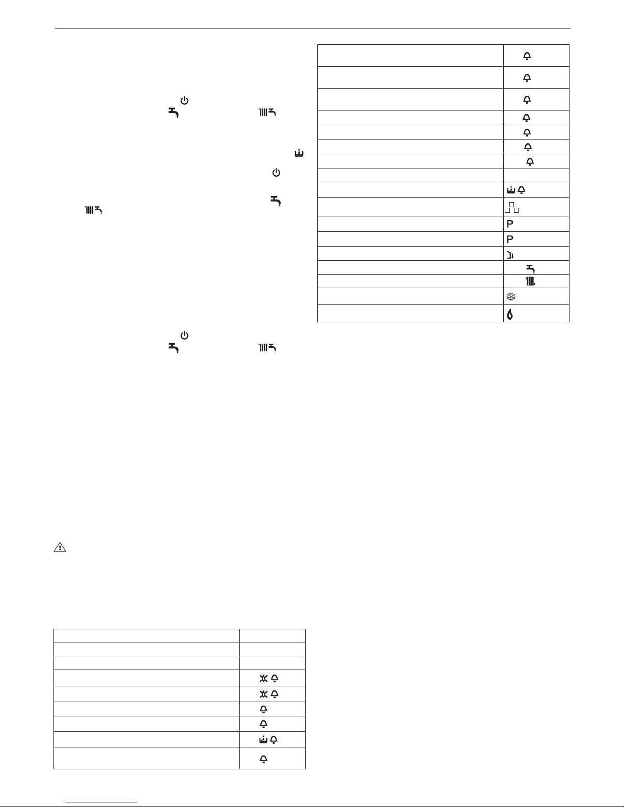
4.4 Light signals and faults
The operating status of the boiler is shown on the digital display,
below is a list of the types of displays.
To restore operation (deactivate alarms):
Faults A 01-02-03
Position the function selector to (OFF), wait 5-6 seconds then
set it to the required position (summer mode) or (winter
mode). If the reset attempts do not reactivate the boiler, contact the
Technical Assistance Centre.
Fault A04
In addition to the fault code, the digital display shows the symbol .
Check the pressure value indicated by the water gauge:
if it is less than 0.3 bar, position the function selector to (OFF)
and adjust the lling tap (B g. 17 for C.S.I. - external for R.S.I.)
until the pressure reaches a value between 1 and 1.5 bar.
Then position the mode selector to the desired position (summer) or (winter).
If pressure drops are frequent, request the intervention of the Technical Assistance Service.
Fault A06
The boiler operates normally but cannot reliably maintain a con-
stant domestic hot water temperature, which remains set at around
50°C. Contact the Technical Assistance Centre.
Fault A07
Contact the Technical Assistance Centre.
Fault A08
Contact the Technical Assistance Centre.
Fault A09
Position the function selector to (OFF), wait 5-6 seconds then
set it to the required position (summer mode) or (winter
mode). If the reset attempts do not reactivate the boiler, request the
intervention of the Technical Assistance Service.
Fault A09
The boiler is equipped with an auto-diagnostic system which, ba-
sed on the total number of hours in certain operating conditions,
can signal the need to clean the primary exchanger (alarm code 09
and flue gas meter >2,500).
Once the cleaning operation has been completed, using the spe-
cial kit supplied as an accessory, the total hour meter will need to
be reset to zero as follows:
- switch off the power supply
remove the shell
- turning the instrument panel towards you
- unscrew the two screws of the small cover on the electronic
board to have access to the terminals
- while the boiler is powered up, using a small screwdriver included,
press the CO button (g. 8) for at least 4 seconds, to check the
meter has been reset, power down then power up the boiler; the
meter reading is shown on the monitor after the “-C-” sign.
Live electrical parts (230 V AC).
Note: the meter resetting procedure should be carried out after
each indepth cleaning of the primary exchanger or if this latter is
replaced. To check the status of the total hour meter, multiply the
reading by 100 (e.g. reading of 18 = 1800 total hours; reading of 1
= 100 total hours). The boiler continues to operate normally even
when the alarm is activated.
BOILER STATUS DISPLAY
Stand-by -
OFF status OFF
ACF module lockout alarm
A01
ACF electrical fault alarm
A01
Limit thermostat alarm
A02
Tacho fan alarm
A03
H2O pressure switch alarm
A04
NTC domestic water fault (R.S.I only with external
storage heater with probe)
A06
Primary (ow) thermistor fault - Primary (ow) thermistor over temperature - Temperature differential
A07
Return thermistor fault - Return thermistor overtemperature - Temperature differential inverted
A08
Flue thermistor or ue thermistor counter fault Flue thermistor over temperature
A09
False ame
A11
Low temperature thermostat fault
A77
Calibration
ADJ
Service operation
ACO
Transient awaiting ignition 88°C ashing
H2O pressure switch intervention
ashing
Purge cycle mode active
Preheating Function active (only C.S.I.)
Preheating heat request (only C.S.I.)
ashing
External probe present
Domestic water heat request
60°C
Heating heat request 80°C
Anti-freeze heat request
Flame present
4.5 Boiler conguration (g. 19)
The electronic board contains a series of jumpers (JP4) that can be
used to configure the boiler.
To access the board, proceed as follows:
- switch off the power supply
- remove the shell
- turning the instrument panel towards you
- unscrew the two screws of the small cover on the electronic
board to have access to the terminals.
JUMPER JP7:
preselection of the most suitable heating temperature adjustment
eld according to the installation type.
Jumper not inserted - standard installation
Standard installation 40-80°C
Jumper inserted - oor installation
Floor installation 20-45°C.
In the manufacturing phase, the boiler is congured for standard
installations.
JP1 Calibration (Range Rated)
JP2 Reset heating timer
JP3 Calibration (see paragraph on “Adjustments”)
JP4 Absolute domestic hot water thermostat selector (C.S.I. model)
JP4 Do not use (R.S.I. model)
JP5 Do not use (C.S.I. model)
JP5 Heating only function with a predisposition for external stor-
age tank with thermostat (JP8 inserted) or probe (JP8 not inserted) (R.S.I. model)
JP6 Enable night-time compensation function and continuous
pump (only with external sensor connected)
JP7 Enable management of low temperature/standard installa-
tions (see above)
JP8 Do not use (C.S.I. model)
JP8 Management of an external storage tank with thermostat ena-
bled (jumper inserted)/ management of an external storage
tank with probe (jumpers not inserted) (R.S.I. model).
4.6 Setting the thermoregulation (graphs 1-2-3 g. 20)
The thermoregulation only operates with the external sensor connected; once installed, connect the external sensor (accessory available on request) to the special terminals provided on the boiler terminal board.
This enables the THERMOREGULATION function.
ENGLISH
11
Selecting the compensation curve
The compensation curve for heating maintains a theoretical temperature of 20°C indoors, when the external temperature is between +20°C and -20°C. The choice of the curve depends on the
minimum external temperature envisaged (and therefore on the
geographical location), and on the delivery temperature envisaged
(and therefore on the type of system). It is carefully calculated by
the installer on the basis of the following formula:
envisaged delivery T. - Tshift
KT=
20- min. envisaged external T.
Tshift = 30°C standard installations
25°C oor installations
If the calculation produces an intermediate value between two
curves, you are advised to choose the compensation curve nearest the value obtained.
Example: if the value obtained from the calculation is 1,3 this is
between curve 1 and curve 1,5. Choose the nearest curve, i.e. 1,5.
Select the KT using trimmer P3 on the board (see multiwire wiring
diagram).
To access P3:
- switch off the power supply
- remove the shell
- turning the instrument panel towards you
- unscrew the two screws of the small cover on the electronic
board to have access to the terminals.
Live electrical parts (230 V AC).
The KT values which can be set are as follows:
- standard installation: 1,0-1,5-2,0-2,5-3,0
- oor installation 0,2-0,4-0,6-0,8
and these are displayed for approximately 3 seconds after rotation
of the trimmer P3.
TYPE OF HEAT REQUEST
Boiler connected to room thermostat (JUMPER 6 not inserted)
The heat request is made by the closure of the room thermostat
contact, while the opening of the contact produces a switch-off.
The delivery temperature is automatically calculated by the boiler,
although the user may modify the boiler settings. Using the inter-
face to modify the HEATING, you will not have the HEATING SETPOINT value available, but a value that you can set as preferred
between 15 and 25°C. The modication of this value will not directly
modify the delivery temperature, but will automatically affect the
calculation that determines the value of that temperature, altering
the reference temperature in the system (0 = 20 °C).
Boiler
connected to a programmable timer (JUMPER JP6 inserted)
With the contact closed, the heat request is made by the delivery
sensor, on the basis of the external temperature, to obtain a nominal
indoor temperature on DAY level (20°C). With the contact open, the
boiler is not switched off, but the weather curve is reduced (parallel
shift) to NIGHT level (16°C).
This activates the night-time function.
The delivery temperature is automatically calculated by the boiler,
although the user may modify the boiler settings.
Using the interface to modify the HEATING, you will not have the
HEATING SET-POINT value available, but a value that you can set
as preferred between 25 and 15°C.
The modication of this value will not directly modify the delivery temperature, but will automatically affect the calculation that determines
the value of that temperature, altering the reference temperature in
the system (0 = 20°C for DAY level, and 16°C for NIGHT level).
4.7 Adjustments
The boiler has already been adjusted by the manufacturer during
production. If the adjustments need to be made again, for example
after extraordinary maintenance, replacement of the gas valve, or
conversion from methane gas to LPG, observe the following pro-
cedures.
The adjustment of the maximum and minimum output, and of the
maximum and minimum heating and of slow switch-on, must be
made strictly in the sequence indicated, and only by qualied per-
sonnel only:
- disconnect the boiler from the power supply
- remove the shell
- turning the instrument panel towards you (g. 7)
- unscrew the two screws of the small cover on the electronic
board to have access to the terminals
- insert the jumpers JP1 and JP3
- power up the boiler.
The display shows “ADJ” for approximately 4 seconds.
Next change the following parameters:
1 - Domestic hot water/absolute maximum
2 - Minimum
3 - Heating maximum
4 - Slow ignition
as follows:
- turn the heating water temperature selector to set the required
value
- press the CO button (g. 8) and then skip to the calibration of the
next parameter.
Live electrical parts (230 V AC).
The following icons light up on the monitor:
1. during domestic hot water/absolute maximum calibration
2. during minimum calibration
3. during heating maximum calibration
4. during slow ignition calibration
End the procedure by removing jumpers JP1 and JP3 to store
these set values in the memory.
The function can be ended at any time without storing the set values in the memory and retaining the original values as follows:
- remove jumpers JP1 and JP3 before all 4 parameters have been set
- set the function selector to (OFF/RESET)
- cut the power supply 15 minutes after it is connected.
Calibration can be carried out without powering up the boiler.
By turning the heating selection knob, the monitor automati-
cally shows the number of rotations, expressed in hundreds
(e.g. 25 = 2,500 rpm).
The function for visualizing the setting parameters is activated by
the function selector in summer and in winter, by pressing the CO
b
utton on the circuit board, either with or without request for heat.
This function cannot be activated when connected to a remote control.
Upon activating the function the setting parameters are visualized
in the order given below, each for 2 seconds. Each parameter is
displayed together with its corresponding icon and fan rotation
speed measured in hundreds:
1. Maximum
2. Minimum
3. Max. heating
4. Slow ignition P
5. Max. preset heating .
GAS VALVE CALIBRATION
- Connect the boiler to the power supply
- Open the gas tap
- Set the function selector to (OFF/RESET) (monitor off)
- Loosen the xing screws (A, g. 6) and remove the shell
- Release the panel and turn it forwards (g. 7)
- Unscrew the two screws of the small cover on the electronic
board to have access to the terminals
- While the boiler is powered up, using a small screwdriver included, press the CO button (g. 8)
Live electrical parts (230 V AC).
- Wait for burner ignition.
The boiler operates at maximum heat output.
The “combustion analysis” function remains active for a limited
time (15 min); if a delivery temperature of 90°C is reached, the
burner is switched off. It will be switched back on when this temperature drops below 78°C.
- Insert the analyser probe in the ports provided in the air distribu-
tion box, after removing the screws from the cover (g. 21)
- Press the “combustion analysis” button a second time to reach
the number of rotations corresponding to the maximum domestic
hot water output (table 1)
- Check the CO2 value: (table 3) if the value does not match the
value given in the table, use the gas valve maximum adjustment
Mynute Green C.S.I. E - R.S.I. E
12
screw
- Press the “combustion analysis” button a third time to reach the
number of rotations corresponding to the minimum output (table 2)
- Check the CO2 value: (table 4) if the value does not match the value
given in the table, use the gas valve minimum adjustment screw
- To exit the “combustion analysis” function, turn the control knob
- Remove the ue gas probe and ret the plug
- Close the instrument panel and ret the housing.
The “combustion analysis” function is automatically deactivated if
the board triggers an alarm. In the event of a fault during the com-
bustion analysis cycle, carry out the reset procedure.
table 1
MAXIMUM NUMBER OF FAN
ROTATIONS
METHANE
GAS (G20)
LIQUID GAS
(G31)
12 R.S.I. heating 54 54 rpm
15 R.S.I. heating 49 49 rpm
25 C.S.I. heating - DHW 56 56 rpm
25 R.S.I. heating 56 56 rpm
30 C.S.I. heating - DHW
55 57 rpm
35 R.S.I. heating
59 59 rpm
38 C.S.I. heating - DHW
50-62 50-62 rpm
table 2
MINIMUM NUMBER OF FAN
ROTATIONS
METHANE
GAS (G20)
LIQUID GAS
(G31)
12 R.S.I. heating 13 18 rpm
15 R.S.I. heating 14 14 rpm
25 C.S.I. heating - DHW 18 18 rpm
25 R.S.I. heating 18 18 rpm
30 C.S.I. heating - DHW
14 14 rpm
35 R.S.I. heating
14 14 rpm
38 C.S.I. heating - DHW
14 14 rpm
table 3
MAXIMUM CO2
METHANE
GAS (G20)
LIQUID GAS
(G31)
12 R.S.I. 9,0 10,0 %
15 R.S.I. 9,0 10,0 %
25 C.S.I. - 25 R.S.I. 9,0 10,0 %
30 C.S.I.
9,0 10,0 %
35 R.S.I.
9,0 10,0 %
38 C.S.I.
9,5 10,5 %
table 4
MINIMUM CO2
METHANE
GAS (G20)
LIQUID GAS
(G31)
12 R.S.I. 9,5 10,0 %
15 R.S.I. 9,5 10,0 %
25 C.S.I. - 25 R.S.I. 9,5 10,0 %
30 C.S.I.
9,5 10,5 %
35 R.S.I.
9,5 10,0 %
38 C.S.I.
9,5 10,5 %
table 5
SLOW IGNITION
METHANE
GAS (G20)
LIQUID GAS
(G31)
12 R.S.I. 37 37 rpm
15 R.S.I. 37 37 rpm
25 C.S.I. - 25 R.S.I. 34 34 rpm
30 C.S.I.
37 37 rpm
35 R.S.I.
37 37 rpm
38 C.S.I.
37 37 rpm
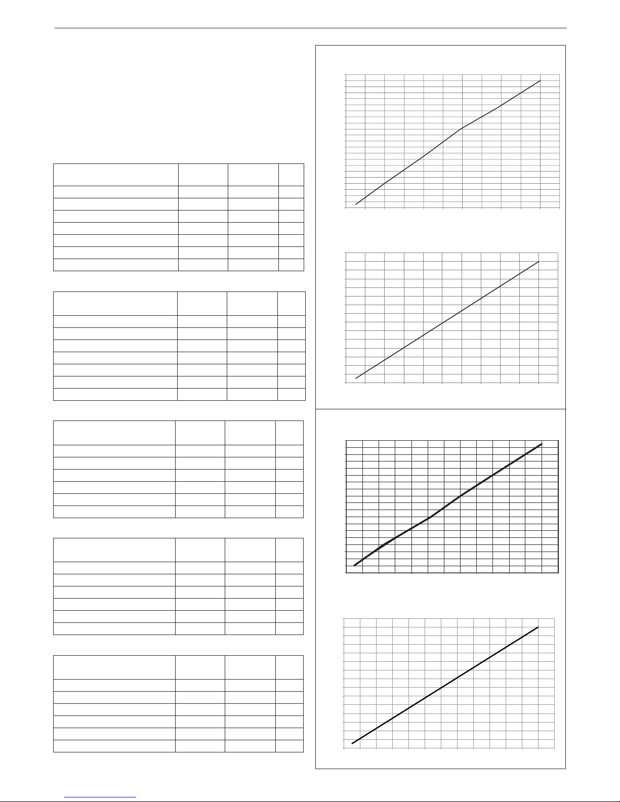
HTG curve (Qnheating)
Fan rotations (rpm)
Heat output (kW)
COs.a. curve (Qnheating)
CO emissions s.a. (p.p.m.)
Heat output (kW)
Mynute Green 12 R.S.I. E
1200
1400
1600
1800
2000
2200
2400
2600
2800
3000
3200
3400
3600
3800
4000
4200
4400
4600
4800
5000
5200
5400
5600
2345678910 11 12 13
10
20
30
40
50
60
70
80
90
100
110
120
130
140
150
160
2345678910 11 12 13
Mynute Green 15 R.S.I. E
HTG curve (Qnheating)
Fan rotations (rpm)
Heat output (kW)
COs.a. curve (Qnheating)
CO emissions s.a. (p.p.m.)
Heat output (kW)
1200
1400
1600
1800
2000
2200
2400
2600
2800
3000
3200
3400
3600
3800
4000
4200
4400
4600
4800
5000
345678910 11 12 13 14 15 16
10
20
30
40
50
60
70
80
90
100
110
120
130
140
150
160
3 4 5 6 7 8 9 10 11 12 13 14 15 16
ENGLISH
13
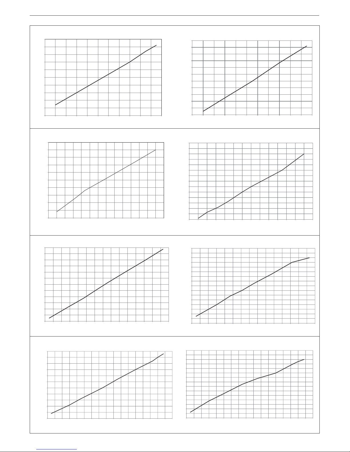
Mynute Green 25 C.S.I. E - 25 R.S.I. E
HTG curve (Qnheating)
Fan rotations (rpm)
Heat output (kW)
COs.a. curve (Qnheating)
CO emissions s.a. (p.p.m.)
Heat output (kW)
1000
1500
2000
2500
3000
3500
4000
4500
5000
5500
6000
468101214161820222
42
6
40
50
60
70
80
90
10
0
11
0
12
0
13
0
14
0
150
468101214161820222426
Mynute Green 30 C.S.I. E
HTG curve (Qnheating)
Fan rotations (rpm)
Heat output (kW)
COs.a. curve (Qnheating)
CO emissions s.a. (p.p.m.)
Heat output (kW)
1000
1500
2000
2500
3000
3500
4000
4500
5000
5500
6000
468101214161820222426283032
10
20
30
40
50
60
70
80
90
100
110
120
130
140
150
468101214161820222426283
03
2
Mynute Green 35 R.S.I. E
HTG curve (Qnheating)
Fan rotations (rpm)
Heat output (kW)
COs.a. curve (Qnheating)
CO emissions s.a. (p.p.m.)
Heat output (kW)
1200
1600
2000
2400
2800
3200
3600
4000
4400
4800
5200
5600
6000
6810 12 14 16 18 20 22 24 26 28 30 32 34 36
20
30
40
50
60
70
80
90
100
110
120
130
140
150
160
170
180
6810 12 14 16 18 20 22 24 26 28 30 32 34 36
Mynute Green 38 C.S.I. E
HTG curve (Qnheating)
Fan rotations (rpm)
Heat output (kW)
COs.a. curve (Qnheating)
CO emissions s.a. (p.p.m.)
Heat output (kW)
1000
1500
2000
2500
3000
3500
4000
4500
5000
5500
6000
6500
6810 12 14 16 18 20 22 24 26 28 30 32 34 36 38 40
0
20
40
60
80
100
120
140
160
180
200
220
240
260
280
300
6810 12 14 16 18 20 22 24 26 28 30 32 34 36 38 40
Mynute Green C.S.I. E - R.S.I. E
14
4.9 Checking the combustion parameters (g. 21)
Mynute Green C.S.I. E:
- Position the function selector on to switch off the boiler
- Turn the DHW temperature selector on .
Wait until the ignition of the burner (about 6 seconds). The dis-
play shows “ACO”, the boiler operates at full power heating.
- Remove the screw C and the cover E on the air box.
- Insert the probes of the analyzer in the positions provided on the
air box.
The ue gas analysis probe must be fully inserted as far
as possible.
- Check that the CO2 values match those given in the table, if the
value shown is different, change it as indicated in the chapter
entitled “Gas valve calibration”.
MAXIMUM CO2
METHANE
GAS (G20)
LIQUID GAS
(G31)
25 C.S.I. 9,0 10,0 %
30 C.S.I.
9,0 10,0 %
38 C.S.I.
9,5 10,5 %
MINIMUM CO2
METHANE
GAS (G20)
LIQUID GAS
(G31)
25 C.S.I. 9,5 10,0 %
30 C.S.I.
9,5 10,5 %
38 C.S.I.
9,5 10,5 %
Mynute Green R.S.I. E:
- Position the function selector on to switch off the boiler.
- Turn the DHW temperature selector on .
Wait until the ignition of the burner (about 6 seconds). The dis-
play shows “ACO”, the boiler operates at full power heating.
- Remove the screw C and the cover E on the air box.
- Insert the probes of the analyzer in the positions provided on the
air box.
The ue gas analysis probe must be fully inserted as far
as possible.
- Check that the CO2 values match those given in the table, if the
value shown is different, change it as indicated in the chapter
entitled “Gas valve calibration”.
MAXIMUM CO2
METHANE
GAS (G20)
LIQUID GAS
(G31)
12 R.S.I. 9,0 10,0 %
15 R.S.I. 9,0 10,0 %
25 R.S.I. 9,0 10,0 %
35 R.S.I.
9,0 10,0 %
MINIMUM CO2
METHANE
GAS (G20)
LIQUID GAS
(G31)
12 R.S.I. 9,5 10,0 %
15 R.S.I. 9,5 10,0 %
25 R.S.I. 9,5 10,0 %
35 R.S.I.
9,5 10,0 %
- Check the ue combustion.
The “combustion analysis” remains active for a time limit of 15 min;
in the event it is reached in a ow temperature of 90 °C the burner
shutdown.
It will turn back when this temperature falls below 78 °C.
If you wish to stop the process turn the hot water temperature in the
area between the “+” and “-”.
Then:
- remove the analyser probe and close the sockets for combustion
analysis with the special screw
- close the instrument panel and refit the housing.
RANGE RATED
This boiler can be adapted to the heating requirements of the sys-
tem, in fact it is possible to set the maximum delivery for heating
operation of the boiler itself:
- switch off the power supply
- setting the heating water temperature selector at the maximum
value
- remove the shell
- turning the instrument panel towards you
- unscrew the two screws of the small cover on the electronic
board to have access to the terminals
- insert JP1 jumper
- power up the boiler.
The display shows “ADJ” for about 4 sec.: it is then possible to
change the maximum heating value by means of the heating water
temperature selector and the CO button in order to set and conrm
the desired value.
The icon will appear on the display.
Finish the procedure by removing the jumper JP1 to store the set
values.
Once the desired output (maximum heating) has been set, note the
value on the table on the back cover.
For subsequent controls and adjustments, refer to the set value.
The calibration does not entail the ignition of the boiler. By ro-
tating the heating setpoint selector knob, the value expressed
in hundreds (e.g. 25 = 2500 rpm) is automatically displayed.
The boiler is supplied with the adjustments shown in the table.
Depending on plant engineering requirements or regional ue gas
emission limits it is, however, possible to modify this value, refer-
ring to the graphs below.
4.8 Gas conversion (g. 22)
Gas conversion from one family of gases to another can also be
easily performed when the boiler is installed.
This operation must be carried out by professionally qualied
personnel. The boiler is designed to operate with methane gas
(G20) according to the product label.
It is possible to convert the boiler to LPG, using the special kit.
For disassembly, refer to the instructions below:
- switch off the power supply to the boiler and close the gas tap
- remove the housing
- remove the xing screw from the instrument panel
- unhook and turn the instrument panel forwards
- remove the gas valve (A)
- remove the nozzle (B) inside the gas valve and replace it with the
nozzle from the kit
- ret the gas valve
- re-power the boiler and turn on the gas tap.
Adjust the boiler as described in the chapter entitled “Adjustments”
with reference to the information on LPG.
Conversion must be carried out by qualied personnel.
Once the conversion is complete, afx the new
identication label supplied in the kit.
If you need to convert Mynute Green 25 C.S.I. - 25 R.S.I.
(clapet inside) from natural gas to other types of gas
you MUST remove the clapet and put the new gasket
contained into the conversion kit.
If you need to convert Mynute Green 25 C.S.I. - 25 R.S.I.
from other gas types to natural gas you need to regulate
G20 values as follows:
G20
Numbers of fan revolutions at slow start rpm/min 3.400
Maximum number of fan rotation (CH-DHW) rpm/min 5.600
Minimum number of fan rotation (CH-DHW) rpm/min 1.800
ENGLISH
15
5 MAINTENANCE
The appliance must be systematically controlled at regular inter-
vals to make sure it works correctly and efciently and conforms to
legislative provisions in force.
The frequency of controls depends on the conditions of installation
and usage, it being anyhow necessary to have a complete check
carried out by authorized personnel from the Servicing Centre every year.
- Check and compare the boiler’s performance with the relative
specications.
Any cause of visible deterioration must be immediately identied
and eliminated.
- Closely inspect the boiler for signs of damages or deterioration,
particularly with the drainage and aspiration system and electrical apparatus.
- Check and adjust – where necessary – all the burner’s parameters.
- Check and adjust – where necessary – the system’s pressure.
- Analyze combustion. Compare results with the product’s specication.
Any loss in performance must be identied and corrected by nd-
ing and eliminating the cause.
- Make sure the main heat exchanger is clean and free of any
residuals or obstruction.
- Check and clean – where necessary – the condensation tray to
make sure it works properly.
IMPORTANT: always switch off the power to the appliance and
close the gas by the gas cock on the boiler before carrying out any
maintenance and cleaning jobs on the boiler.
Do not clean the appliance or any latter part with ammable substances (e.g. petrol, alcohol, etc.).
Do not clean panelling, enamelled and plastic parts with paint sol-
vents.
Panels must be cleaned with ordinary soap and water only.
MAINTENANCE FOR PRESSURISED COLLECTIVE CHIMNEY
In the event of maintenance operations on the boiler which
require the ue gas pipes to be disconnected, a cap should be
placed on the open element originating from the pressurised
smoke pipe.
In the event of fan removal check that the non return valve is
properly positioned in the correct side - see pages 167-168.
Failure to adhere to the guidelines provided can compromise
the security of persons and animals due to potential leakages
of carbon monoxide from the smoke pipe.
USER
1A GENERAL WARNINGS
The instruction manual is an integral part of the product and it must
therefore be kept carefully and must accompany the appliance; if
the manual is lost or damaged, another copy must be requested
from the Technical Assistance Service.
Boiler installation and any other assistance and maintenance
operation must be carried out by qualied personnel according to current local and national regulations.
For installation, it is advisable to contact specialised personnel.
The boiler must only be used for the application foreseen by
the manufacturer. The manufacturer shall not be liable for
any damage to persons, animals or property due to errors in
installation, calibration, maintenance or due to improper use.
The safety and automatic adjustment devices must not be modi-
ed, during the system life cycle, by the manufacturer or supplier.
This appliance produces hot water, therefore it must be con-
nected to a heating system and/or a domestic hot water
mains, compatible with its performance and output.
In case of water leakage, close the water supply and contact
the Technical Assistance Service immediately.
In case of absence for long periods time, close the gas supply
and switch off the electrical supply main switch. In case of risk
of frost, empty the boiler.
From time to time check that the operating pressure of the
hydraulic system does not decrease under 1 bar.
In case of failure and/or malfunctioning, deactivate the appli-
ance, and do not try to repair or intervene directly on it.
Appliance maintenance must be carried out at least once a
year: program it with the Technical Assistance Service will
avoid wasting time and money.
When the product reaches the end of its life it should not be
disposed of as solid urban waste but should be brought to a
separated waste collection facility.
Boiler use requires to strictly observe some basic safety rules:
Do not use the appliance in any manner other than its in-
tended purpose.
It is dangerous to touch the appliance with wet or damp body
parts and/or in bare feet.
Under no circumstances cover the intake grids, dissipation
grids and ventilation vents in the installation room with cloths,
paper or any other material.
Do not activate electrical switches, telephone or any other object
that causes sparks if there is a smell of gas. Ventilate the room
by opening doors and windows and close the gas central tap.
Do not place anything in the boiler.
Do not perform any cleaning operation if the appliance is not
disconnected from the main power supply.
Do not cover or reduce ventilation opening of the room where
the generator is installed.
Do not leave containers and inammable products in the in-
stallation room.
Do not attempt to repair the appliance in case of failure and/
or malfunctioning.
It is dangerous to pull or twist the electric cables.
Children or unskilled persons must not use the appliance.
Do not intervene on sealed elements.
For better use, remember that:
- a periodic external cleaning with soapy water not only improves
its aesthetic aspect but also preserves panelling from corrosion,
extending its life cycle;
- if the wall-mounted boiler is enclosed in pendant furniture, leave
at least 5 cm for ventilation and maintenance;
- installation of an room thermostat will favour a greater comfort, a
more rational use of the heat and energy saving; the boiler can
also be connected to a programming clock in order to manage
ignition and switching off during the day or week.
Mynute Green C.S.I. E - R.S.I. E
16
2A IGNITION
First ignition must be carried out by personnel from the Technical
Assistance Service. At the same time, if it is necessary to put the
appliance in service again, carefully follow the described operations.
To start-up the boiler it is necessary to carry out the following operations:
- power the boiler
- open the gas tap present in the system to allow fuel ow
- turn the mode selector (3 - g. 1a) to the desired position:
Mynute Green C.S.I. E:
Summer mode: turning the selector to the symbol summer
(g. 3a) the traditional function of only domestic hot water is activated. If there is a domestic hot water request the digital display
shows the hot water system temperature, the icon to indicate the
hot water supply and the ame icon.
Winter mode: by turning the mode selector within the area
marked + and - (g. 3b), the boiler provides domestic hot water
and heating. If there is a heat request, the boiler switches on
and the digital monitor indicates the heating water temperature,
the icon to indicate heating and the ame icon (g. 4a). If there
is a domestic hot water request, the boiler switches on and the
digital display shows the hot water system temperature, the icon
to indicate the hot water supply and the ame icon (g. 4b).
Pre-heating (faster hot water): rotate the domestic hot wa-
ter temperature adjustment knob (4 - g. 1a) to the sym-
bol (g. 5a), to activate the pre-heating function. This func-
tion keeps the water in the domestic hot water exchanger
hot, to reduce standby times when a request is made. When
the pre-heating function is enabled, the monitor indicates
the delivery temperature of the heating water or the domestic
hot water, according to the current request. During burner ignition following a pre-heating request, the monitor indicates the
symbol (g. 5b). To deactivate the pre-heating function, rotate
the domestic hot water temperature adjustment knob back to the
symbol. Bring the domestic hot water temperature adjustment
knob back to the required position. This function cannot be activated
when the boiler is OFF: function selector (3 - g.1a) on OFF.
Positioning the mode selector to (OFF) and the domestic
hot water temperature adjustment knob (4 - g. 1a) to the
symbol, the chimney sweep function is activated (for exclusive
use of the Technical Assistance Service).
Mynute Green R.S.I. E:
Summer mode (only with the external water tank connected):
turning the selector to the symbol summer (g. 3a) the tra-
ditional function of only domestic hot water is activated and the
boiler supplies water at the temperature set on the external storage tank. If there is a domestic hot water request the digital dis-
play shows the hot water system temperature, the icon to indicate the hot water supply and the ame icon
Winter mode: by turning the mode selector within the area
marked + and - (g. 3b), the boiler provides hot water for heating
and - if connected to an external storage tank - domestic hot wa-
ter. If there is a heat request, the boiler switches on and the digital monitor indicates the heating water temperature, the icon to
indicate heating and the ame icon (g. 4a). If there is a domestic
hot water request, the boiler switches on and the digital display
shows the hot water system temperature, the icon to indicate the
hot water supply and the ame icon (g. 4b).
Positioning the mode selector to (OFF) and the domestic
hot water temperature adjustment knob (4 - g. 1a) to the
symbol, the chimney sweep function is activated (for exclusive
use of the Technical Assistance Service).
- Adjust the room thermostat to the required temperature (~20°C).
Adjustment of the heating water temperature
To adjust the heating water temperature, turn the knob with symbol
(g. 3b) within the area marked + and -.
Depending on the type of system, it is possible to pre-select the
suitable temperature range:
- standard systems 40-80°C
- oor systems 20-45°C.
For further details, consult the “Boiler conguration” section.
Adjusting heating water temperature with an external probe
connected
When an external probe is connected, the value of the delivery temperature is automatically chosen by the system which rapidly adjusts
ambient temperature to the changes in external temperature.
To increase or decrease the temperature with respect to the value
automatically calculated by the electronic board, turn the heating
water selector (g. 3b) clockwise to increase and anticlockwise to
decrease. Adjustment settings range from comfort levels - 5 to + 5
which are indicated on the digital display when the knob is turned.
Mynute Green C.S.I. E:
Adjustment of domestic hot water temperature
To adjust domestic water temperature (bathrooms, showers, kitchen, etc.), turn the knob with symbol (g. 3b) within the area
marked + and -.
The boiler is standby status until, after a heat request, the burner
switches on and the digital display shows the hot water system tem-
perature, the icon to indicate the hot water supply and the ame icon
The boiler will be in function until the adjusted temperature is
reached, afterwards it will be in “standby” again.
Mynute Green R.S.I. E:
Adjustment of the domestic hot water temperature
CASE A heating only - adjustment does not apply.
CASE B heating only + external storage tank with thermostat - ad-
justment does not apply.
CASE C heating only + external storage tank with probe - to adjust
the temperature of the domestic hot water in the storage tank, turn
the knob-but with the symbol clockwise to increase water temperature and anti-clockwise to lower it.
The boiler is standby status until, after a heat request, the burner
switches on and the digital display shows the hot water system tem-
perature, the icon to indicate the hot water supply and the ame
icon. The boiler will be in function until the adjusted temperature is
reached, afterwards it will be in “standby” again.
Environment Automatic Adjustment System Function
(S.A.R.A.) g. 7a
By setting the heating water temperature selector to the area
marked by AUTO - temperature value from 55 to 65°C - the
S.A.R.A. self-adjusting system is activated: the boiler varies the
delivery temperature according to the closing signal of the room
thermostat. When the temperature set with the heating water tem-
perature selector is reached, a 20 minutes count begins. If during
this period the room thermostat still requests heat, the value of the
set temperature automatically increases by 5 °C.
When the new value is reached, other 20 minutes count begins.
If during this period the room thermostat still requests heat, the
value of the set temperature automatically increases by 5 °C.
This new temperature value is the result of the temperature set
manually with the heating water temperature selector and the increase of +10 °C of the S.A.R.A function.
After the second cycle the temperature value should be kept at the
set value +10°C until the request of the room thermostat is met.
3A SWITCHING OFF
Temporary switching off
In case of absence for short periods of time, set the mode selector
(3 - g. 1a) to (OFF) (g. 2a).
In this way (leaving the electricity and fuel supplies enabled), the
boiler is protected by the following systems:
- Anti-frost device: when the temperature of the water in the boil-
er falls below 5°C, the circulator and, if necessary, the burner are
activated at minimum output levels to bring the water temperature back to the values for safety (35°C). During the anti-frost
cycle, the symbol appears on the digital monitor.
- Circulator anti-blocking function: an operation cycle is acti-
vated every 24 hours.
- DHW Antifreeze (only when connected to an external stor-
age tank with probe): the function is activated if the temperature
measured by the storage tank probe drops below 5° C. A heat request is generated in this phase with the ignition of the burner at
minimum power, which is maintained until the water temperature
reaches 55° C. During the anti-frost cycle, the symbol appears
on the digital monitor.
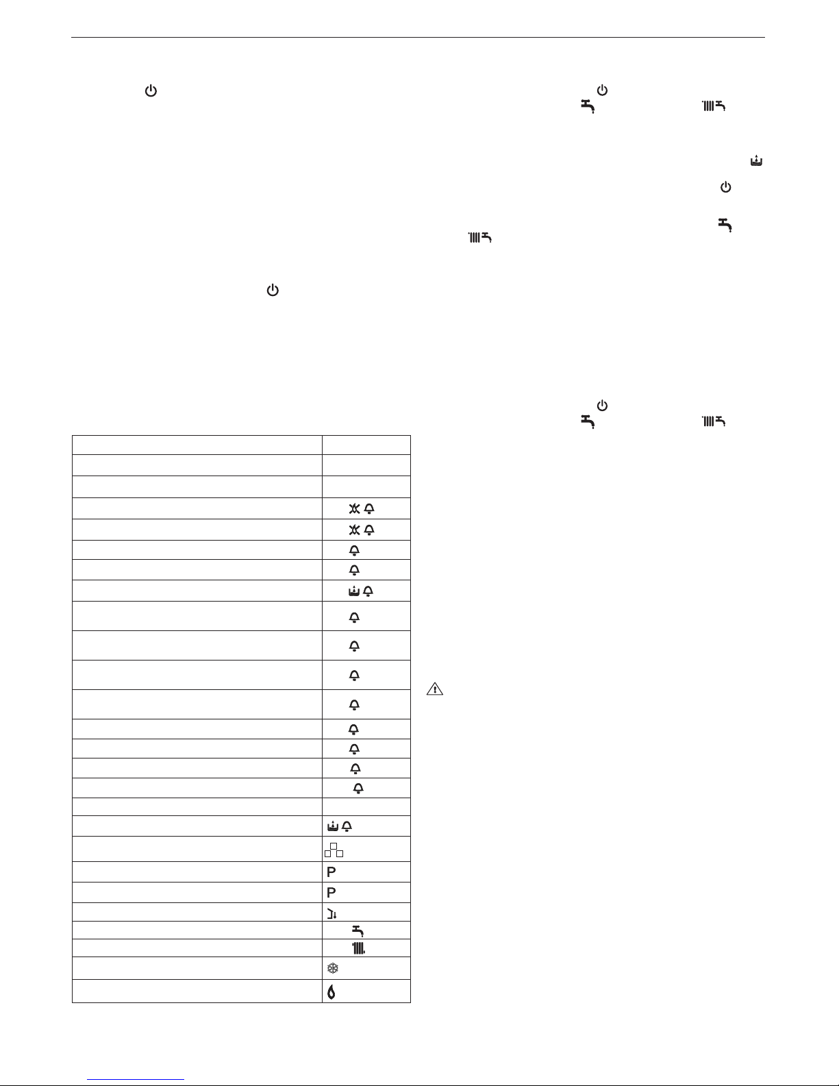
ENGLISH
17
Long period switching off
In case of absence for long periods of time, set the mode selector
(3 - g. 1a) to (OFF) (g. 2a).
Then, close the gas tap present on the system. In this case, antifrost device is deactivated: empty the systems, in case of risk of
frost.
4A CONTROLS
At the beginning of the heating season, and occasionally during
use, make sure the hydrometer-thermohydrometer indicates cold
system pressure values between 0.6 and 1.5 bar: this avoids sys-
tem noise levels due to the presence of air. In case of insufcient
water circulation, the boiler will switch off. Under no circumstances,
water pressure must be below 0.5 bar (red eld).
If this condition is checked, it is necessary to restore water pres-
sure in the boiler proceeding as follows:
- set the mode selector (3 - g.1a) to (OFF)
- turn on the lling tap (B g. 17 for C.S.I. - external for R.S.I.) until
the pressure value is between 1 and 1.5 bar.
Carefully close the tap. Replace the mode selector on the initial
position. If pressure drop is frequent, contact the Technical Assistance Service.
5A LIGHT SIGNALS AND FAULTS
The operating status of the boiler is shown on the digital display,
below is a list of the types of displays.
BOILER STATUS DISPLAY
Stand-by -
OFF status OFF
ACF module lockout alarm
A01
ACF electrical fault alarm
A01
Limit thermostat alarm
A02
Tacho fan alarm
A03
H2O pressure switch alarm
A04
NTC domestic water fault (R.S.I only with external
storage heater with probe)
A06
Primary (ow) thermistor fault - Primary (ow) thermistor over temperature - Temperature differential
A07
Return thermistor fault - Return thermistor overtemperature - Temperature differential inverted
A08
Flue thermistor or ue thermistor counter fault Flue thermistor over temperature
A09
False ame
A11
Low temperature thermostat fault
A77
Calibration
ADJ
Service operation
ACO
Transient awaiting ignition 88°C ashing
H2O pressure switch intervention
ashing
Purge cycle mode active
Preheating Function active (only C.S.I.)
Preheating heat request (only C.S.I.)
ashing
External probe present
Domestic water heat request 60°C
Heating heat request 80°C
Anti-freeze heat request
Flame present
To restore operation (deactivate alarms):
Faults A 01-02-03
Position the function selector to (OFF), wait 5-6 seconds then
set it to the required position (summer mode) or (winter
mode). If the reset attempts do not reactivate the boiler, contact the
Technical Assistance Centre.
Fault A04
In addition to the fault code, the digital display shows the symbol .
Check the pressure value indicated by the water gauge:
if it is less than 0.3 bar, position the function selector to (OFF)
and adjust the lling tap (B g. 17 for C.S.I. - external for R.S.I.)
until the pressure reaches a value between 1 and 1.5 bar.
Then position the mode selector to the desired position (summer) or (winter).
If pressure drops are frequent, request the intervention of the Technical Assistance Service.
Fault A06
The boiler operates normally but cannot reliably maintain a con-
stant domestic hot water temperature, which remains set at around
50°C. Contact the Technical Assistance Centre.
Fault A07
Contact the Technical Assistance Centre.
Fault A08
Contact the Technical Assistance Centre.
Fault A09
Position the function selector to (OFF), wait 5-6 seconds then
set it to the required position (summer mode) or (winter
mode). If the reset attempts do not reactivate the boiler, request the
intervention of the Technical Assistance Service.
Fault A09
The boiler is equipped with an auto-diagnostic system which, based on the total number of hours in certain operating conditions,
can signal the need to clean the primary exchanger (alarm code 09
and flue gas meter >2,500).
Once the cleaning operation has been completed, using the special kit supplied as an accessory, the total hour meter will need to
be reset to zero as follows:
- switch off the power supply
- remove the shell
- turning the instrument panel towards you
- unscrew the two screws of the small cover on the electronic
board to have access to the terminals
- while the boiler is powered up, using a small screwdriver included,
press the CO button (g. 8) for at least 4 seconds, to check the
meter has been reset, power down then power up the boiler; the
meter reading is shown on the monitor after the “-C-” sign.
Live electrical parts (230 V AC).
Note: the meter resetting procedure should be carried out after
each indepth cleaning of the primary exchanger or if this latter is
replaced. To check the status of the total hour meter, multiply the
reading by 100 (e.g. reading of 18 = 1800 total hours; reading of 1
= 100 total hours).
The boiler continues to operate normally even when the alarm is
activated.
Mynute Green C.S.I. E - R.S.I. E
18
TECHNICAL DATA
DESCRIPTION
Mynute Green 25 C.S.I. E Mynute Green 30 C.S.I. E Mynute Green 38 C.S.I. E
Heating Heat input kW
25,00 30,00 30,00
kcal/h 21.500 25.800 25.800
Maximum heat output (80/60°C) kW 24,50 29,10 29,31
kcal/h 21.070 25.026 25.207
Maximum heat output (50/30°C) kW 26,25 31,62 31,95
kcal/h 22.575 27.193 27.477
Minimum heat input (**) kW 6,00 6,00 7,00
kcal/h
5.160 5.160 6.020
Minimum heat output (80/60°C) kW 5,89 5,90 6,85
kcal/h 5.067 5.072 5.888
Minimum heat output (50/30°C) kW 6,48 6,46 7,51
kcal/h 5.573 5.557 6.459
Nominal Range Rated heat output (Qn) kW 25,00 30,00 30,00
kcal/h
21.500 25.800 25.800
Minimum Range Rated heat output (Qm) kW
6,00 6,00 7,00
kcal/h 5.160 5.160 6.020
DHW Heat input kW 25,00 30,00 38,00
kcal/h 21.500 25.800 32.680
Maximum heat output (*) kW 25,00 30,00 38,00
kcal/h 21.500 25.800 32.680
Minimum heat input (**) kW 6,00 6,00 7,00
kcal/h 5.160 5.160 6.020
Minimum heat output (*) kW 6,00 6,00 7,00
kcal/h
5.160 5.160 6.020
** = 6,0 kW with collective pressurised chimney (3CEP) - ONLY FOR 25 C.S.I.
(*) average value of various DHW operating conditions
Useful efficiency Pn max - Pn min (80°/60°) % 98 - 98,2 97 - 98,3 97,7 - 97,8
Useful efciency 30% (47° return) % 102,3 103,1 102,4
Combustion performance % 98,3 97,2 97,9
Useful efficiency Pn max - Pn min (50°/30°) % 105,0 - 108,0 105,4 - 107,7 106,5 - 107,3
Useful efciency 30% (30° return) % 107,1 108,9 108,2
Average Range Rated efciency Pn (80°/60°) % 98,6 97,7 98,1
Average Range Rated efciency Pn (50°/30°) %
105,8 106,4 106,8
Electric power W 80 98 105
Circulator electric power (1.000 l/h) W 40 39 40
Category II2H3P II2H3P II2H3P
Country of destination - - Power supply voltage V - Hz 230 - 50 230 - 50 230 - 50
Degree of Protection IP X5D X5D X5D
Pressure drops on flue with burner on % 1,73 2,82 2,15
Pressure drops on flue with burner off % 0,11 0,10 0,12
Heating operation
Pressure - maximum temperature bar - °C 3 - 90 3 - 90 3 - 90
Minimum pressure for standard operation bar 0,25 - 0,45 0,25 - 0,45 0,25 - 0,45
Selection field of heating water temperature °C 20/45 - 40/80 20/45 - 40/80 20/45 - 40/80
Pump: maximum head available mbar 250 250 250
for system capacity l/h 1.000 1.000 1.000
Membrane expansion tank l 8 10 10
Expansion tank pre-charge bar 1 1 1
DHW operation
Maximum pressure bar 6 6 6
Minimum pressure bar
0,15 0,15 0,15
Hot water quantity with ∆t 25°C l/min
14,3 17,2 21,8
with ∆t 30°C l/min
11,9 14,3 18,2
with ∆t 35°C l/min 10,2 12,3 15,6
DHW minimum output l/min 2 2 2
Selection field of DHW temperature °C 37 - 60 37 - 60 37 - 60
Flow regulator l/min 11 13 15
Gas pressure
Methane gas nominal pressure (G20) mbar 20 20 20
LPG liquid gas nominal pressure (G31) mbar 37 37 37
Hydraulic connections
Heating input - output Ø 3/4” 3/4” 3/4”
DHW input-output Ø 1/2” 1/2” 1/2”
Gas input Ø
3/4” 3/4” 3/4”
ENGLISH
19
DESCRIPTION
Mynute Green
12 R.S.I. E
Mynute Green
15 R.S.I. E
Mynute Green
25 R.S.I. E
Mynute Green
35 R.S.I. E
Heating Heat input kW 12,00 15,00 25,00 34,60
kcal/h 10.320 12.900 21.500 29.756
Maximum heat output (80/60°C) kW 11,75 14,64 24,50 33,67
kcal/h 10.103 12.590 21.070 28.953
Maximum heat output (50/30°C) kW 12,71 15,75 26,25 36,71
kcal/h 10.929 13.545 22.575 31.571
Minimum heat input (**) kW 2,50 - 3,50 (G31) 3,50 6,00 7,00
kcal/h 2.150 - 3.010 (G31) 3.010 5.160 6.020
Minimum heat output (80/60°C) kW 2,44 - 3,42 (G31) 3,46 5,89 6,85
kcal/h 2.101 - 2.944 (G31) 2.977 5.067 5.888
Minimum heat output (50/30°C) kW 2,70 - 3.75 (G31) 3,76 6,48 7,51
kcal/h 2.318 - 3.227 (G31) 3.230 5.573 6.459
Nominal Range Rated heat output (Qn) kW 12,00 15,00 25,00 34,60
kcal/h 10.320 12.900 21.500 29.756
Minimum Range Rated heat output (Qm) kW 2,50 - 3,50 (G31) 3,50 6,00 7,00
kcal/h 2.150 - 3.010 (G31) 3.010 5.160 6.020
** = 6,0 kW with collective pressurised chimney (3CEP) - ONLY FOR 25 R.S.I.
Useful efficiency Pn max - Pn min (80°/60°) %
97,9 - 97,7
(min 97,8 G31)
97,6 - 98,9 98 - 98,2 97,3 - 97,8
Useful efficiency 30% (47° return) % 102,1 101,8 102,3 102,7
DESCRIPTION
Mynute Green 25 C.S.I. E Mynute Green 30 C.S.I. E Mynute Green 38 C.S.I. E
Boiler dimensions
Height mm 780 780 780
Width mm 400 450 450
Depth of housing mm 358 358 358
Boiler weight kg 37 41 44
Flow rate (G20)
Air capacity Nm3/h 31,237 37,361 35,395 44,362
Flue gas capacity Nm3/h 33,744 40,371 38,404 48,134
Mass flow of flue gas (max-min) gr/s 11,32 - 2,58 13,538 - 2,568 12,838-2,996 16,091-2,996
Flow rate (G31)
Air capacity Nm3/h
31,485 38,102 36,288 45,481
Flue gas capacity Nm3/h
33,416 39,266 37,451 46,939
Mass flow of flue gas (max-min) gr/s 11,78 - 2,70 13,256 - 2,523 12,615-2,944 15,811-2,944
Fan performance
Residual head of boiler without pipes Pa 180 105 105
Residual head of concentric pipes 0,85 m Pa 45 40 25
Residual head of separate pipes 0,5 m Pa 150 84 95
Max pressure allowed with pressurised collective chimney Pa
50 - -
Concentric flue gas discharge pipes
Diameter mm 60-100 60-100 60-100
Maximum length m 7,85 7,85 3,85
Drop due to insertion of a 45°/90° bend m 1,3/1,6 1,3/1,6 1,3/1,6
Hole in wall (diameter) mm
105 105 105
Concentric flue gas discharge pipes
Diameter mm 80-125 80-125 80-125
Maximum length m 14,85 14,85 10
Drop due to insertion of a 45°/90° bend m 1/1,5 1/1,5 1/1,5
Hole in wall (diameter) mm 130 130 130
Separate flue gas discharge pipes
Diameter mm 80 80 80
Maximum length m 36+36 30+30 30+30
Losses for a 45°/90° bend m 1/1,5 1/1,5 1/1,5
Installation B23P–B53P
Diameter mm 80 80 80
Maximum length of drainage pipe m 60 47 45
NOx class 5 5 5
Emission values at max. and min. rate of gas G20*
Maximum - Minimum CO s.a. less than ppm 145 - 45 130 - 12 200 - 30
CO
2
% 9,0 - 9,5 9,0 - 9,5 9,5 - 9,5
NOx s.a. lower than ppm 35 - 30 30 - 25 40 - 25
Flue gas temperature °C
79 - 57 77 - 59 74 - 61
* Check performed with concentric pipe ø 60-100, length 0,85m - water temperature 80-60°C

Mynute Green C.S.I. E - R.S.I. E
20
DESCRIPTION
Mynute Green
12 R.S.I. E
Mynute Green
15 R.S.I. E
Mynute Green
25 R.S.I. E
Mynute Green
35 R.S.I. E
Combustion performance % 98,4 97,9 98,3 97,5
Useful efciency Pn max - Pn min (50°/30°) %
105,9 - 107,8
(min 107,2 G31)
105,0 - 107,3 105,0 - 108,0 106,1 - 107,3
Useful efciency 30% (30° return) % 110 109,6 107,1 109,1
Average Range Rated efciency Pn (80°/60°) % 98,4 98,5 98,6 97,7
Average Range Rated efciency Pn (50/30°) % 106,6 106,1 105,8 106,8
Electric power W 74 72 80 100
Circulator electric power (1.000 l/h) W 40 40 40 40
Category II2H3P II2H3P II2H3P II2H3P
Country of destination - - - Power supply voltage V - Hz 230 - 50 230 - 50 230 - 50 230 - 50
Degree of Protection IP X5D X5D X5D X5D
Pressure drops on flue with burner on % 1,57 2,13 1,73 2,53
Pressure drops on flue with burner off % 0,15 0,19 0,11 0,13
Heating operation
Pressure - maximum temperature bar - °C 3 - 90 3 - 90 3 - 90 3 - 90
Minimum pressure for standard operation bar 0,25 - 0,45 0,25 - 0,45 0,25 - 0,45 0,25 - 0,45
Selection field of heating water temperature °C 20/45 - 40/80 20/45 - 40/80 20/45 - 40/80 20/45 - 40/80
Pump: maximum head available mbar 250 250 250 250
for system capacity l/h 1.000 1.000 1.000 1.000
Membrane expansion tank l 8 8 8 10
Expansion tank pre-charge bar 1 1 1 1
Gas pressure
Methane gas nominal pressure (G20) mbar 20 20 20 20
LPG liquid gas nominal pressure (G31) mbar 37 37 37 37
Hydraulic connections
Heating input - output Ø 3/4” 3/4” 3/4” 3/4”
Water tank delivery - output Ø 3/4” 3/4” 3/4” 3/4”
Gas input Ø 3/4” 3/4” 3/4” 3/4”
Boiler dimensions
Height mm 780 780 780 780
Width mm 400 400 400 450
Depth of housing mm 358 358 358 358
Boiler weight kg 36 36 37 41
Flow rate (G20)
Air capacity Nm3/h 14,994 18,742 31,237 43,090
Flue gas capacity Nm3/h 16,197 20,246 33,744 46,561
Mass flow of flue gas (max-min) gr/s 5,435 - 1,074 6,793 - 1,503 11,32 - 2,58 15,614 - 2,996
Flow rate (G31)
Air capacity Nm3/h 15,113 18,891 31,485 43,945
Flue gas capacity Nm3/h 16,040 20,050 33,416 45,286
Mass flow of flue gas (max-min) gr/s 5,654 - 1,574 7,068 - 1,574 11,78 - 2,70 15,288 - 2,944
Fan performance
Residual head of boiler without pipes Pa 90 100 180 140
Residual head of concentric pipes 0,85 m Pa 45 55 45 60
Residual head of separate pipes 0,5 m Pa 60 70 150 122
Max pressure allowed with pressurised collective chimney
Pa - - 50 -
Concentric flue gas discharge pipes
Diameter mm 60-100 60-100 60-100 60-100
Maximum length m 7,85 7,85 7,85 7,85
Drop due to insertion of a 45°/90° bend m 1,3/1,6 1,3/1,6 1,3/1,6 1,3/1,6
Hole in wall (diameter) mm 105 105 105 105
Concentric flue gas discharge pipes
Diameter mm 80-125 80-125 80-125 80-125
Maximum length m 14,85 14,85 14,85 14,85
Drop due to insertion of a 45°/90° bend m 1/1,5 1/1,5 1/1,5 1/1,5
Hole in wall (diameter) mm 130 130 130 130
Separate flue gas discharge pipes
Diameter mm 80 80 80 80
Maximum length m 60+60 50+50 36+36 26+26
Losses for a 45°/90° bend m 1/1,5 1/1,5 1/1,5 1/1,5
Installation B23P–B53P
Diameter mm 80 80 80 80
Maximum length of drainage pipe m 90 80 60 40
NOx class 5 5 5 5
ENGLISH
21
Multigas table
DESCRIPTION Methane gas (G20) Propane (G31)
Lower Wobbe index (at 15°C-1013 mbar) MJ/m3S 45,67 70,69
Net Caloric Value
MJ/m3S
MJ/KgS
34,02
-
88
46,34
Supply nominal pressure
mbar
mm W.C.
20
203,9
37
377,3
Supply minimum pressure (25 C.S.I. - 30 C.S.I. - 12 R.S.I. - 25 R.S.I.)
mbar
mm W.C.
8
81,6
-
Supply minimum pressure (38 C.S.I. - 15 R.S.I. - 35 R.S.I.)
mbar
mm W.C.
10
102,0
-
Mynute Green 25 C.S.I. E
Burner: number of nozzles - diameter of nozzles - lenght n° - mm - mm 1 - 63 - 130 1 - 63 - 130
Diaphragm: number of holes - diameter of holes n° - mm 1 - 6,7 1 - 4,7
Heating maximum gas capacity Sm3/h 2,64
kg/h 1,94
DHW maximum gas capacity Sm3/h 2,64
kg/h 1,94
Heating minimum gas capacity Sm3/h 0,63
kg/h 0,47
DHW minimum gas capacity Sm3/h 0,63
kg/h 0,47
Numbers of fan revolutions at slow start rpm/min 3.400 3.400
Maximum number of fan revolutions (CH) rpm/min 5.600 5.600
Maximum number of fan revolutions (DHW) rpm/min 5.600 5.600
Minimum number of fan revolutions (CH) rpm/min 1.800 1.800
Minimum number of fan revolutions (DHW) rpm/min 1.800 1.800
Minimum number of fan revolutions with collective pressurised chimney (3CEP)
rpm/min 2.200 -
Mynute Green 30 C.S.I. E
Burner: number of nozzles - diameter of nozzles - lenght n° - mm - mm 1 - 63 - 130 1 - 63 - 130
Diaphragm: number of holes - diameter of holes n° - mm 1 - 6 1 - 4,5
Heating maximum gas capacity Sm3/h 3,17
kg/h 2,33
DHW maximum gas capacity Sm3/h 3,17
kg/h 2,33
Heating minimum gas capacity Sm3/h 0,63
kg/h 0,47
DHW minimum gas capacity Sm3/h 0,63
kg/h 0,47
Numbers of fan revolutions at slow start rpm/min 3.700 3.700
Maximum number of fan revolutions (CH) rpm/min 5.500 5.700
Maximum number of fan revolutions (DHW) rpm/min 5.500 5.700
Minimum number of fan revolutions (CH) rpm/min 1.400 1.400
Minimum number of fan revolutions (DHW) rpm/min 1.400 1.400
Mynute Green 38 C.S.I. E
Burner: number of nozzles - diameter of nozzles - lenght n° - mm - mm 1 - 63 - 140 1 - 63 - 140
Diaphragm: number of holes - diameter of holes n° - mm 1 - 7 1 - 5
Heating maximum gas capacity Sm3/h 3,17
kg/h 2,33
DHW maximum gas capacity Sm3/h 4,02
kg/h 2,95
Heating minimum gas capacity Sm3/h 0,74
kg/h 0,54
DHW minimum gas capacity Sm3/h 0,74
kg/h 0,54
DESCRIPTION
Mynute Green
12 R.S.I. E
Mynute Green
15 R.S.I. E
Mynute Green
25 R.S.I. E
Mynute Green
35 R.S.I. E
Emission values at max. and min. rate of gas G20*
Maximum - Minimum CO s.a. less than ppm 150 - 15 150 - 15 145 - 45 160 - 35
CO
2
% 9,0 - 9,5 9,0 - 9,5 9,0 - 9,5 9,0 - 9,5
NOx s.a. lower than ppm 35 - 20 30 - 25 35 - 30 30 - 35
Flue gas temperature °C 65 - 58 70 - 60 79 - 57 78 - 61
* Check performed with concentric pipe ø 60-100, length 0,85m - water temperature 80-60°C
Mynute Green C.S.I. E - R.S.I. E
22
DESCRIPTION Methane gas (G20) Propane (G31)
Numbers of fan revolutions at slow start rpm/min 3.700 3.700
Maximum number of fan revolutions (CH) rpm/min 5.000 5.000
Maximum number of fan revolutions (DHW) rpm/min 6.200 6.200
Minimum number of fan revolutions (CH) rpm/min 1.400 1.400
Minimum number of fan revolutions (DHW) rpm/min 1.400 1.400
Mynute Green 12 R.S.I. E
Burner: number of nozzles - diameter of nozzles - lenght n° - mm - mm 1 - 70 - 90 1 - 70 - 90
Diaphragm: number of holes - diameter of holes n° - mm 1 - 3,6 1 - 3
Heating maximum gas capacity Sm3/h 1,27
kg/h 0,93
Heating minimum gas capacity Sm3/h 0,26
kg/h 0,27
Numbers of fan revolutions at slow start rpm/min 3.700 3.700
Maximum number of fan revolutions (CH) rpm/min 5.400 5.400
Minimum number of fan revolutions (CH) rpm/min 1.300 1.800
Mynute Green 15 R.S.I. E
Burner: number of nozzles - diameter of nozzles - lenght n° - mm - mm 1 - 70 - 90 1 - 70 - 90
Diaphragm: number of holes - diameter of holes n° - mm 1 - 4,7 1 - 3,6
Heating maximum gas capacity Sm3/h 1,59
kg/h 1,16
Heating minimum gas capacity Sm3/h 0,37
kg/h 0,14
Numbers of fan revolutions at slow start rpm/min 3.700 3.700
Maximum number of fan revolutions (CH) rpm/min 4.900 4.900
Minimum number of fan revolutions (CH) rpm/min 1.400 1.400
Mynute Green 25 R.S.I. E
Burner: number of nozzles - diameter of nozzles - lenght n° - mm - mm 1 - 63 - 130 1 - 63 - 130
Diaphragm: number of holes - diameter of holes n° - mm 1 - 6,7 1 - 4,7
Heating maximum gas capacity Sm3/h 2,64
kg/h 1,94
Heating minimum gas capacity Sm3/h 0,63
kg/h 0,47
Numbers of fan revolutions at slow start rpm/min 3.400 3.400
Maximum number of fan revolutions (CH) rpm/min 5.600 5.600
Minimum number of fan revolutions (CH) rpm/min 1.800 1.800
Minimum number of fan revolutions with collective pressurised chimney (3CEP)
rpm/min 2.200
Mynute Green 35 R.S.I. E
Burner: number of nozzles - diameter of nozzles - lenght n° - mm - mm 1 - 63 - 140 1 - 63 - 140
Diaphragm: number of holes - diameter of holes n° - mm 1 - 6,7 1 - 5
Heating maximum gas capacity Sm3/h 3,66
kg/h 2,69
Heating minimum gas capacity Sm3/h 0,74
kg/h 0,54
Numbers of fan revolutions at slow start rpm/min 3.700 3.700
Maximum number of fan revolutions (CH) rpm/min 5.900 5.900
Minimum number of fan revolutions (CH) rpm/min 1.400 1.400
ENGLISH
23
Parameter Symbol
Mynute Green
25 C.S.I. E
Mynute Green
30 C.S.I. E
Mynute Green
38 C.S.I. E
Unit
Seasonal space heating energy efciency class - A A A Water heating energy efciency class - A A A -
Rated heat output Pnominal 25 29 29 kW
Seasonal space heating energy efciency ηs 92 93 92 %
Useful heat output
At rated heat output and high-temperature regime (*) P4 24,5 29,1 29,3 kW
At 30% of rated heat output and low-temperature
regime (**)
P1 8,0 9,8 9,7 kW
Useful efciency
At rated heat output and high-temperature regime (*) η4 88,8 88,0 88,3 %
At 30% of rated heat output and low-temperature
regime (**)
η1 96,4 98,1 97,4 %
Auxiliary electricity consumption
At full load elmax 40,0 59,0 52,0 W
At part load elmin 13,7 19,4 17,3 W
In Stand-by mode PSB 2,4 2,4 2,4 W
Other parameters
Stand-by heat loss Pstby 58,0 58,0 58,0 W
Pilot ame energy consumption Pign - - - W
Annual energy consumption QHE 48 54 57 GJ
Sound power level, indoors LWA 51 54 54 dB
Emissions of nitrogen oxides NOx 27 24 26 mg/ kWh
For combination heaters
Declared load prole XL XL XL
Water heating energy efciency ηwh 85 85 84 %
Daily electricity consumption Qelec 0,173 0,105 0,157 kWh
Daily fuel consumption Qfuel 22,934 23,097 23,124 kWh
Annual electricity consumption AEC 38 23 34 kWh
Annual fuel consumption AFC 17 17 17 GJ
(*) High-temperature regime means 60 °C return temperature at heater inlet and 80 °C feed temperature at heater outlet.
(**) Low temperature means for condensing boilers 30 °C, for low-temperature boilers 37 °C and for other heaters 50 °C return
temperature (at heater inlet).
Mynute Green C.S.I. E - R.S.I. E
24
Parameter Symbol
Mynute
Green
12 R.S.I. E
Mynute
Green
15 R.S.I. E
Mynute
Green
25 R.S.I. E
Mynute
Green
35 R.S.I. E
Unit
Seasonal space heating energy efciency class - A A A A Water heating energy efciency class - - - - - -
Rated heat output Pnominal 12 15 25 34 kW
Seasonal space heating energy efciency ηs 93 93 92 93 %
Useful heat output
At rated heat output and high-temperature regime (*) P4 11,7 14,6 24,5 33,7 kW
At 30% of rated heat output and low-temperature
regime (**)
P1 4,0 4,9 8,0 11,3 kW
Useful efciency
At rated heat output and high-temperature regime (*) η4 88,6 88,7 88,8 88,0 %
At 30% of rated heat output and low-temperature
regime (**)
η1 99,1 98,7 96,4 98,2 %
Auxiliary electricity consumption
At full load elmax 34,0 32,0 40,0 60,0 W
At part load elmin 11,9 11,3 13,7 19,7 W
In Stand-by mode PSB 2,4 2,4 2,4 2,4 W
Other parameters
Stand-by heat loss Pstby 58,0 49,0 58,0 69,0 W
Pilot ame energy consumption Pign - - - - W
Annual energy consumption QHE 22 28 48 63 GJ
Sound power level, indoors LWA 49 48 51 54 dB
Emissions of nitrogen oxides NOx 23 29 27 28 mg/ kWh
For combination heaters
Declared load prole - - - Water heating energy efciency ηwh - - - - %
Daily electricity consumption Qelec - - - - kWh
Daily fuel consumption Qfuel - - - - kWh
Annual electricity consumption AEC - - - - kWh
Annual fuel consumption AFC - - - - GJ
(*) High-temperature regime means 60 °C return temperature at heater inlet and 80 °C feed temperature at heater outlet.
(**) Low temperature means for condensing boilers 30 °C, for low-temperature boilers 37 °C and for other heaters 50 °C return
temperature (at heater inlet).
25
FRANÇAIS
1 - DISPOSITIFS DE SÉCURITÉ GÉNÉRAUX
Nos chaudières sont construites dans nos usines et vériées dans
les moindres détails an de protéger les utilisateurs et installateurs
de toute lésion. Après avoir travaillé sur le produit, le personnel qualié doit vérier les branchements électriques, en particulier la partie
dénudée des conducteurs, qui ne doit pas sortir du bornier, en évitant
tout contact possible avec des parties sous tension dudit conducteur.
Ce manuel d'instructions est partie intégrante du produit: assu-
rez-vous qu'il reste toujours avec l'appareil, même en cas de
cession à un autre propriétaire ou utilisateur ou en cas de mise
en place sur une autre installation. En cas de perte ou de dom-
mage, contacter votre Service technique après-vente pour en
obtenir un nouvel exemplaire.
L'installation de la chaudière et toute autre opération d'assistance
et de entretien doivent être réalisées par un personnel qualié
selon les réglementations locales et nationales en vigueur.
Il est conseillé à l'installateur d'informer l'utilisateur sur le fonction-
nement de l'appareil et sur les règles fondamentales de sécurité.
Cette chaudière ne peut être utilisée qu'aux ns prévues. Le fa-
bricant décline toute responsabilité contractuelle et non contractuelle en cas de blessures à des personnes ou des animaux ou
en cas de dommages aux biens dérivés d'erreurs d'installation,
de réglage ou d'entretien, ou d'une utilisation inappropriée.
Cet appareil est utilisé pour produire de l'eau chaude et doit donc
être raccordé à un chauffage et/ou un système d'eau chaude
sanitaire, selon ses performances et sa puissance.
Une fois le produit déballé, s'assurer que tous ses composants sont
intacts et complets. Dans le cas contraire, s'adresser au distributeur.
Les dispositifs de sécurité et de réglage automatique de l'appa-
reil ne doivent jamais être modiés pendant toute leur durée de
vie, sauf par le fabricant ou le distributeur.
Si l'appareil tombe en panne et/ou ne fonctionne pas correcte-
ment, il faut l'éteindre et faire appel à des experts (ne pas essayer de le réparer soi-même).
Le produit en n de vie ne doit pas être éliminé comme ordure
ménagère solide mais doit être remis à un centre de tri sélectif.
La sortie de la vanne de sécurité doit être raccordée à un sys-
tème de collecte et de purge adapté. Le fabricant décline toute
responsabilité pour tout dommage provoqué à une intervention
réalisée sur la vanne de sécurité.
Jeter tous les matériaux d'emballage dans les récipients adaptés
dans les centres de collecte correspondants.
Jeter les déchets en veillant à ne pas endommager la santé
humaine et sans employer de procédures ou méthodes susceptibles d'endommager l'environnement.
Raccorder le collecteur de sortie à un système d'évacuation
approprié (se référer au chapitre 3.5).
Pendant l'installation, informer l'utilisateur que:
• en cas de fuites, il faut couper l'alimentation en eau et en informer
immédiatement le Service technique après-vente
• la pression de fonctionnement du système est comprise entre 1 et 2
bars et ne doivent jamais dépasser 3 bars. Si nécessaire, réinitialiser
la pression comme indiqué dans le paragraphe intitulé “Remplissage
du système”
• s'il est prévu de ne pas utiliser la chaudière sur une longue période,
il faut appeler le Service technique après-vente pour réaliser les opérations suivantes:
- couper l'interrupteur principal de la chaudière et l'interrupteur
général du système.
- fermer les robinets de gaz et d'eau sur les circuits de chauffage
(C.S.I. - R.S.I.) et d'eau chaude sanitaire (C.S.I.)
- purger les circuits de chauffage (C.S.I. - R.S.I.) et d'eau chaude
sanitaire (C.S.I.) pour éviter le gel.
Mesures de sécurité:
La chaudière ne doit pas être utilisée par des enfants ou des
personnes handicapées sans surveillance.
Aucun dispositif ou équipement électrique (interrupteurs, appa-
reils, etc.) ne doit être employé en présence d'odeur de gaz ou
de fumées. en cas de fuite de gaz, ouvrir toutes les portes et
fenêtres pour ventiler la zone, fermer le robinet général de gaz et
appeler immédiatement le service technique après-vente.
Ne pas toucher la chaudière avec les pieds nus ou avec une
partie du corps mouillée ou humide.
Avant les opérations de nettoyage, débrancher la chaudière de
l'alimentation principale en mettant l'interrupteur de système de
position et l'interrupteur de panneau de commande principal.
Il est interdit de modier les dispositifs de sécurité ou de réglage
sans l'autorisation et les instructions du fabricant.
Ne pas tirer, dénuder ou tordre les ls de la chaudière même s'ils
ne sont pas branchés sur l'alimentation électrique.
Ne pas bloquer ou réduire la taille des ouvertures de ventilation
de la pièce.
Ne pas laisser de récipients ou substances inammables dans la
pièce.
Tenir l'emballage hors de portée des enfants.
Il est interdit de bloquer la sortie des condensats.
2 - INSTALLATION DE LA CHAUDIÈRE
La chaudière ne doit être installée que par un personnel qualié,
conformément à la législation en vigueur.
Mynute Green E est disponible dans les modèles suivants :
Mynute Green C.S.I. E sont des chaudières à condensation murales
de type C pour le chauffage et la production d'eau chaude sanitaire.
Mynute Green R.S.I. E sont des chaudières à condensation murales
de type C capables de fonctionner dans différentes conditions par le
biais d'une série de cavaliers installés sur la carte électronique (consulter la section “Conguration de la chaudière”):
CAS A: chauffage seul. La chaudière ne fournit pas d'eau chaude sanitaire.
CAS B: chauffage seul avec un réservoir d'eau contrôlé par thermostat:
dans cette condition, la chaudière fournit de l'eau chaude au réservoir
d'eau si une demande est faite par le thermostat correspondant.
CAS C: chauffage seul avec un réservoir d'eau contrôlé par une sonde
de température (kit d'accessoire disponible sur demande) pour la production d'eau chaude. Si le réservoir d'eau n'est pas fourni par notre
société, assurez-vous que la sonde NTC correspondante a les caractéristiques suivantes: 10 kOhm à 25°C, B 3435 ±1%.
Selon le dispositif de sortie de gaz de cheminée, les chaudières sont
classées en catégories B23P, B53P, C13, C23, C33, C43, C53, C63,
C83, C93, C13x, C33x, C43x, C53x, C63x, C83x, C93x.
Dans la conguration B23P et B53P (en cas d'installation à l'intérieur),
l'appareil ne peut pas être installé dans des pièces utilisées comme
chambre à coucher, salle de bain, douche ou possédant des cheminées ouvertes sans afux d'air. La pièce où la chaudière sera installée
devra avoir une ventilation appropriée.
En conguration C, l'appareil peut être installé dans n'importe quel type
de pièce et il n'y a aucune limitation liée aux conditions de ventilation
ou au volume de la pièce.
3 - RÈGLES POUR L'INSTALLATION
3.1 Règles pour l'installation
L'installation doit être réalisée par un personnel qualié.
Respecter toujours les réglementations nationales et locales.
Mynute Green E peut être installé à l'intérieur.
La chaudière a une protection qui garantit un fonctionnement correct
avec une gamme de températures de 0°C à 60°C.
Pour bénécier des protections, l'appareil doit être en mesure de
démarrer, puisque n'importe quelle condition de déverrouillage (par
exemple, absence de gaz ou d'alimentation électrique, ou intervention
de sécurité) désactive les protections.
Les symboles suivants sont employés dans ce manuel:
PRÉCAUTION = opérations qui exigent un soin particulier et une
préparation adéquate.
NON AUTORISÉ = opérations qui NE DOIVENT PAS être réalisées
R.S.I.: Les fonctions ECS sont applicables uniquement si un réservoir
d'eau est raccordé (accessoire disponible sur demande).
INSTALLATEUR
FR

26
Mynute Green C.S.I. E - R.S.I. E
DISTANCES MINIMALES
An d'accéder à la chaudière pour effectuer des opérations de entretien régulières, respecter les espaces minimums prévus pour l'installation (g. 1a).
Pour un positionnement correct de l'appareil, il faut tenir compte des
aspects suivants:
- ne le placer pas sur une cuisinière ou un autre dispositif de cuisine
- ne laisser pas de produits inammables dans la pièce où la chaudière est installée
- les murs sensibles à la chaleur (par exemple ceux en bois) doivent
être protégés à l'aide d'une isolation convenable.
IMPORTANT
Avant l'installation, laver chaque tuyau du système minutieusement
an d'éliminer les résidus qui pourraient altérer le fonctionnement de
l'appareil.
Sous la vanne de sécurité, installer un entonnoir de collecte d'eau avec
la décharge correspondante en cas de fuites dues à la surpression du
système de chauffage. Le circuit de l'eau chaude sanitaire n'a pas be-
soin de soupape de sécurité, mais il faut s'assurer que la pression du
conduit d'eau ne dépasse pas 6 bars. En cas de doute, il sera conve-
nable d'installer un réducteur de pression.
Avant d'allumer la chaudière, s'assurer que celle-ci est prévue pour
fonctionner avec le gaz disponible. Ceci peut être repéré dans
l'inscription sur l'emballage et dans l'étiquette adhésive reportant le
type de gaz.
Il est très important de signaler que dans certains cas les conduits de
fumées sont sous pression, donc les jonctions de plusieurs éléments
doivent être hermétiques.
SYSTÈME ANTIGEL
La chaudière est équipée de série d'un système antigel automatique qui
s'active lorsque la température de l'eau du circuit primaire est inférieure
à 0 °C. Ce système est toujours actif et il garantit la protection de la chau-
dière jusqu'à une température extérieure de -3 °C. Pour proter de cet
protection (par rapport au fonctionnement du brûleur), la chaudière doit
être en mesure de s'allumer elle seule ; cela signie que toute condition
de blocage (ex. manque de gaz ou d'alimentation électrique, ou encore
déclenchement d'un dispositif de sécurité) désactive la protection. La
protection antigel est active même lorsque la chaudière est en stand-
by. Dans des conditions normales de fonctionnement, la chaudière
est capable de s'autoprotéger du gel. Au cas où l'appareil serait laissé
longtemps hors tension dans des zones soumises à des températures
inférieures à 0 °C et qu'on ne souhaiterait pas vidanger l'installation de
chauffage, il est conseillé d'utiliser un liquide antigel de qualité dans
le circuit primaire. Suivre attentivement les instructions du fabricant
concernant non seulement le pourcentage de liquide antigel à utiliser
pour la température minimale à laquelle vous souhaitez maintenir le
circuit de la machine mais également la durée et le mode d'élimination
du liquide antigel.
Pour la partie sanitaire, il est conseillé de vider le circuit. Les matériaux
utilisés pour la fabrication des composants des chaudières sont résistants aux liquides antigel à base de glycols éthyléniques.
3.2 Nettoyage du système et caractéristiques de l'eau
du circuit de chauffage
En cas d'une nouvelle installation ou d'un remplacement de la chaudière,
il faut effectuer un nettoyage préventif de l'installation de chauffage.
An de garantir le bon fonctionnement du dispositif, ajouter les additifs
et/ou traitements chimiques (ex. liquides antigel, agents protecteurs,
etc.), et vérier si les paramètres du tableau respectent les valeurs
indiquées.
Paramètres
Unité de
mesure
Eau chaude
chauffage
Eau de rem-
plissage
valeur pH 7–8 Dureté °F - 15–20
Aspect - clair
3.3 Fixation de la chaudière au mur et raccordements
hydrauliques
Pour xer la chaudière au mur, utiliser la barre (g. 3) dans l'emballage.
La position et la taille des raccordements hydrauliques sont indiquées
ci-dessous:
A Retour CH 3/4”
B Départ CH 3/4”
C gas connection 3/4”
D Puissance ECS 1/2” (C.S.I.) - 3/4” (R.S.I.)
E Entrée ECS 1/2” (C.S.I.) - 3/4” (R.S.I.)
Si la dureté de l'eau dépasse 28°Fr, il est recommandé d'utiliser des
adoucisseurs d'eau, an d'éviter tout dépôt calcaire dans la chaudière
à cause de la dureté excessive de l'eau.
3.4 Installation du capteur extérieur (g. 2)
Le bon fonctionnement de la sonde extérieure est fondamental à celui
du contrôle climatique.
INSTALLATION ET BRANCHEMENT DU CAPTEUR EXTÉRIEUR
Installer le capteur sur un mur extérieur de l'édice à chauffer, en observant les indications suivantes:
monter le capteur sur la façade la plus fréquemment exposée au vent
(sur le mur orienté vers le NORD ou le NORD-OUEST), à l'abri du rayonnement solaire direct; le monter à environ 2/3 de la hauteur de la façade;
ne pas le monter près des portes, fenêtres, orices d'évacuation des
conduits d'air, conduits de fumées ou autres sources de chaleur.
Le branchement électrique au capteur extérieur doit être effectué
avec un câble bipolaire d'une section de 0,5 à 1mm2 (non fourni de
série), d'une longueur maximale de 30 mètres. La polarité du câble
de connexion au capteur extérieur n'a aucune importance. Éviter
d'effectuer des jonctions sur ce câble; au cas où celles-ci seraient
nécessaires, elles doivent être étanches et bien protégées. Toute canalisation du câble de connexion éventuellement nécessaire doit être
séparée des câbles sous tension (230 Vac).
FIXATION AU MUR DU CAPTEUR EXTÉRIEUR
Installer le capteur sur une partie lisse du mur; En cas de briques appa-
rentes ou des murs irréguliers, il faut prévoir une zone de contact de
préférence lisse. Dévisser le tôle de protection supérieur en plastique
en le tournant dans le sens inverse des aiguilles d'une montre.
Identier le lieu de xation au mur et réaliser le perçage pour la cheville
à expansion de 5x25. Insérer la cheville dans le trou. Retirer la carte
de son siège.
Fixer le boîtier au mur en utilisant la vis fournie de série. Accrocher
la bride et serrer la vis. Dévisser l'écrou du passe-câble, introduire le
câble de connexion du capteur et le brancher à la borne électrique.
Pour le branchement électrique du capteur extérieur à la chaudière,
consulter le chapitre “Branchement électrique”.
Ne pas oublier de bien fermer le passe-câble pour éviter que
l'humidité de l'air entre son ouverture.
Replacer la carte dans son siège.
Fermer le tôle de protection supérieur en plastique en le tournant dans
le sens des aiguilles d'une montre. Serrer fermement le passe-câble.
3.5 Récupération des condensats
L'installation doit être réalisée de manière à éviter la congélation des
condensats produits par la chaudière (ex. en l'isolant). Il est conseillé
d'installer un collecteur d'évacuation spécial en polypropylène (dispo-
nible sur le marché) sur la partie inférieure de la chaudière (orice Ø
42), comme indiqué sur la g.4. Placer le tuyau exible d'évacuation
des condensats fourni avec la chaudière et le connecter au collecteur
(ou autre dispositif de raccordement pouvant être inspecté) en évitant
de créer des courbes où la condensation pourrait stagner et éventuellement geler. Le fabricant décline toute responsabilité pour des
dommages éventuellement causés par le manque d'écoulement de la
condensation ou par sa congélation.
La ligne de raccordement de vidange doit être parfaitement scellée et
bien protégée contre le risque de gel.
Avant le démarrage initial de l'appareil, vérier que le condensat sera
convenablement vidangé.
3.6 Raccordement de gaz
Avant de raccorder l'appareil à l'alimentation de gaz, vérier que :
- les réglementations d'installation nationales et locales sont respectées
- le type de gaz est adapté pour l'appareil
- la canalisation est propre.
Le tuyau de gaz doit être installé à l'extérieur. Si le tuyau passe à tra-
vers le mur, il doit passer à travers l'ouverture centrale, dans la partie
inférieure du gabarit.
Il est conseillé d'installer un ltre de dimensions appropriées sur la
ligne de gaz au cas où le réseau de distribution contiendrait des parti-
cules solides.
Une fois l'installation effectuée, vérier si les jonctions réalisées sont
étanches comme prévu par les règles d'installation en vigueur.
3.7 Branchement électrique
Pour accéder aux branchements électriques, procéder comme suit :
- éteindre l'interrupteur général du système
- desserrer les vis de xation (A) et enlever la coque (g. 6)
- libérer le panneau et le tourner vers l'avant (g. 7)
- dévisser les deux vis sur le petit couvercle de la carte électronique
pour accéder aux bornes (g. 9-10).

27
FRANÇAIS
Brancher l'appareil à l'alimentation générale à l'aide d'un interrupteur
en observant une distance d'au moins 3,5 mm (EN 60335-1, catégorie
III) entre chaque l.
L'appareil fonctionne avec un courant alternatif de 230 Volt/50 Hz et est
conforme à la norme EN 60335-1.
Connecter la chaudière à un circuit de terre sûr conformément à la
législation en vigueur.
L'installateur est responsable d'assurer une mise à la terre appro-
priée de l'appareil. le fabricant décline toute responsabilité pour
tout dommage dérivant d'une mise à la terre incorrecte ou omise.
Les connexions phase et neutre (L-N) sont également à respecter.
Le conducteur de terre doit être quelques centimètres plus long
que les autres.
La chaudière fonctionne en alimentation phase-neutre ou phase-phase.
Pour l'alimentation ottante, sans conducteur mis à la terre, il est nécessaire d'utiliser un transformateur d'isolation avec un enroulement
secondaire à la terre. Ne pas utiliser de tuyaux de gaz et/ou d'eau
pour la mise à la terre des appareils électriques.
Utiliser le câble électrique fourni pour brancher la chaudière à l'alimentation générale. Connecter le thermostat ambiant et/ou l'horloge programmable extérieure comme indiqué sur le schéma électrique.
Lors du remplacement du câble électrique, utiliser un câble HAR
H05V2V2-F, 3x 0,75 mm2, max. Ø extérieur 7 mm.
3.8 Remplissage de l'installation de chauffage (g. 17)
Une fois les raccordements hydrauliques réalisés, il est possible de
remplir l'installation de chauffage.
Cette opération doit être réalisée avec le système froid, selon les instructions suivantes:
- ouvrir la purge d'air automatique en tournant le bouchon sur la vanne
inférieure (A) et la vanne supérieure (E) sur deux ou trois tours, pour
purger l'air en continu, laisser les bouchons de vanne A-E ouverts
- s'assurer que le robinet d'entrée d'eau froide est ouvert
- ouvrir le robinet de remplissage B (à l'extérieur du système pour le
modèle R.S.I.) jusqu'à ce que la pression indiquée par la jauge d'eau
soit comprise entre 1 et 1,5 bar
- fermer le robinet de remplissage.
REMARQUE: la chaudière est automatiquement purgée par le biais de
deux soupapes de purge automatiques A et E, positionnées sur le cir-
culateur et à l'intérieur de la boîte de distribution d'air respectivement.
En cas de problèmes pour purger la chaudière, procéder comme décrit
au paragraphe 3.11.
3.9 Vidange du système de chauffage (g. 17)
Avant de commander à vidanger le système, couper l'alimentation en
plaçant l'interrupteur général du système sur “éteint”.
Fermer les dispositifs d'arrêt sur le système de chauffage.
Desserrer manuellement la vanne de purge du système (C).
L’eau de l’installation est évacuée à travers le collecteur des points
d’évacuation (D).
3.10 Purge du système d'eau chaude sanitaire (unique-
ment modèle C.S.I., g. 17)
Lorsqu'il y a un risque de gel, le système d'eau chaude sanitaire doit
être vidé de la façon suivante:
- fermer le robinet principal du réseau de distribution d'eau général
- ouvrir tous les robinets d'eau chaude et froide
- purger les points les plus bas.
REMARQUE
Le collecteur des points d’évacuation doit être relié à l’aide d’un tuyau
en caoutchouc (non fourni) à un système de collecte et de refoulement
dans le système d’évacuation des eaux pluviales et dans le respect
des normes en vigueur. Le diamètre extérieur du collecteur est de 20
mm : il est par conséquent conseillé d’utiliser un tuyau en caoutchouc
Ø18-19 mm à fermer à l’aide d’un collier (non fourni).
Le producteur n’est pas responsable des éventuels dommages provoqués par l’absence de système de collecte approprié
3.11 Suggestions pour purger correctement l'air du circuit de chauffage et de la chaudière
Lors de l'installation de la chaudière ou lors d'opérations de entretien
extraordinaire, procéder comme suit :
1. Utiliser une clé CH11 pour ouvrir la vanne de purge manuelle située au
dessus du caisson d'air (g. 5) : raccorder le tuyau fourni avec la chaudière à la vanne an de décharger l'eau dans un récipient extérieur.
2. Ouvrir le robinet de remplissage manuel sur l'ensemble hydrau-
lique et atteindre que l'eau commence à s'écouler de la vanne.
3. Alimenter la chaudière en laissant le robinet de gaz fermé.
4. Utiliser le thermostat ambiant ou le télécommande à distance pour
activer la demande de chaleur de sorte que la vanne à trois voies
se tourne en position de chauffage.
5. Tourner un robinet pour activer la demande d'eau chaude (uniquement pour chaudières instantanées; utiliser le thermostat de
chauffage d'eau pour des chaudières chauffage seul, raccordées
à un chauffage d'eau extérieur) pour un intervalle de 30” chaque
minute pour permettre le cycle de trois voies du chauffage à l'eau
chaude et inversement environ dix fois (la chaudière se mettra en
état d'alerte car il n'y a pas de gaz dans ces circonstances, elle doit
donc être réinitialisée à chaque fois que cela arrive).
6. Poursuivre la séquence jusqu'à ce que l'eau sorte seulement de la
vanne de purge d'air manuelle et que le ux d'air se termine; fermer
la vanne de purge d'air manuelle à ce stade.
7. Vérier que la pression du système est correcte (1 bar est la valeur
idéale).
8. Fermer le robinet de remplissage manuel sur l'ensemble hydraulique.
9. Ouvrir le robinet de gaz et allumer la chaudière.
3.12 Échappement de fumées et admission d'air
Pour l'échappement de fumées, voir les réglementations locales et
nationales en vigueur. Se conformer toujours aux normes locales du
Département Incendie, de la compagnie du gaz et des dispositions
municipales éventuelles.
La libération de produits de combustion est assurée par un ventilateur centrifuge placé à l'intérieur de la chambre de combustion et son
bon fonctionnement est constamment vérié par un pressostat. La
chaudière est fournie sans le kit d'évacuation des fumées/aspiration
d'air, car il est possible d'utiliser les accessoires pour des appareils à
chambre étanche à tirage forcé qui mieux s'adaptent aux caractéristiques typologiques d'installation. Il est essentiel pour la libération de
gaz de combustion et le rétablissement de l'air de combustion de la
chaudière d'utiliser des conduits certiés et que la connexion soit réalisée correctement comme indiqué par les instructions fournies avec
les accessoires de gaz de combustion. Avec un seul tuyau de fumée,
vous pouvez connecter davantage de pièces d'appareil à condition que
chaque pièce d'appareil soit de type à chambre scellée.
CONFIGURATIONS DE SORTIES POSSIBLES (g. 11)
B23P/B53P Aspiration intérieure et évacuation extérieure
C13-C13x Évacuation via refoulement mural concentrique. Les tuyaux
peuvent partir indépendamment de la chaudière, mais les sorties
doivent être concentriques ou sufsamment proches
pour être soumises à des conditions de vent similaires (sur 50 cm)
C23 Évacuation concentrique dans un conduit de fumées commun
(aspiration et évacuation dans le même conduit)
C33-C33x Évacuation via refoulement concentrique au plafond. Sorties comme pour C13
C43-C43x Évacuation et aspiration dans des conduits de fumées com-
muns séparés, mais soumis à des conditions de vent similaires
C53-C53x Évacuation et aspiration séparées murales ou au plafond
et en zones avec des pressions différentes. Les lignes de décharge et
d'aspiration ne doivent jamais être positionnées sur des parois opposées
C63-C63x Tuyaux de refoulement et d'aspiration vendus et certiés
séparément (1856/1)
C83-C83x Refoulement via conduit de fumées traditionnel et tuyau
d'aspiration mural
C93-C93x Refoulement au plafond (similaire à C33) et aspiration d'air
par un conduit de fumées simple.
INSTALLATION À OUVERTURE FORCÉE (B23P-B53P)
Conduit de refoulement de fumées Ø 80 mm (g. 12)
Le conduit de sortie des fumées peut être orienté dans le sens le plus
approprié selon les exigences d'installation.
Pour l'installer, suivre les instructions fournies avec le kit.
Dans cette conguration, la chaudière est connectée au conduit de sor-
tie des fumées de Ø 80 mm au moyen d'un adaptateur de Ø 60-80 mm.
La conguration B23p/B53P est interdite en cas d’installation
dans une cheminée collective pressurisée.
Dans ce cas, l'air de support de combustion est prélevé dans la
pièce où est installée la chaudière (qui doit être une pièce tech-
nique adaptée avec une ventilation correcte).
Les conduits de sortie des fumées non isolés sont des sources
potentielles de danger.
Le conduit de sortie des fumées doit être incliné de 3° vers la
chaudière.
La chaudière adapte automatiquement la ventilation au type
d'installation et à la longueur du conduit.
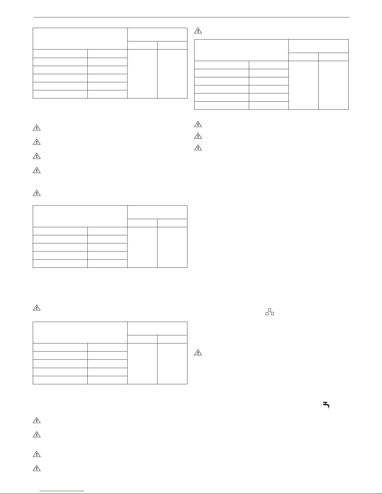
28
Mynute Green C.S.I. E - R.S.I. E
Longueur max. du conduit
de sortie des fumées Ø 80 mm
Pertes de charge de
chaque coude (m)
45° 90°
12 R.S.I. 90 m
1 1,5
15 R.S.I. 80 m
25 C.S.I. - 25 R.S.I. 60 m
30 C.S.I. 47 m
35 R.S.I. 40 m
38 C.S.I. 45 m
ÉVACUATIONS CONCENTRIQUES (Ø 60-100) (g. 13)
Les évacuations concentriques peuvent être placées dans la direction
la plus adaptées pour les exigences de l'installation, en respectant les
longueurs maximales indiquées dans le tableau.
Le conduit de sortie des fumées doit être incliné de 3° vers la
chaudière.
Les conduits de sortie des fumées non isolés sont des sources
potentielles de danger.
La chaudière adapte automatiquement la ventilation au type
d'installation et à la longueur du conduit.
Ni boucher ni réduire en aucun cas le conduit d'entrée d'air com-
burant.
Pour l'installation, suivre les instructions fournies avec les kits.
Longueur rectiligne signie sans coudes, embouts de sortie ni
raccords.
Longueur linéaire maximum
concentrique
concentrique Ø 60-100 mm
Pertes de charge de
chaque coude (m)
45° 90°
12 R.S.I. - 15 R.S.I. 7,85 m
1,3 1,6
25 C.S.I. - 25 R.S.I. 7,85 m
30 C.S.I. 7,85 m
35 R.S.I. 7,85 m
38 C.S.I. 3,85 m
Conduits concentriques (Ø 80-125)
Le kit d'adaptateur correspondant doit être installé pour cette configuration. Des conduits concentriques peuvent être disposés dans la
direction la plus adaptée pour les exigences d'installation.
Pour l'installation, suivre les instructions fournies avec les kits spécifiques pour les chaudières à condensation.
Longueur rectiligne signie sans coudes, embouts de sortie ni
raccords.
Longueur linéaire maximum
concentrique
concentrique Ø 80-125 mm
Pertes de charge de
chaque coude (m)
45° 90°
12 R.S.I. - 15 R.S.I. 14,85 m
1 1,5
25 C.S.I. - 25 R.S.I. 14,85 m
30 C.S.I. 14,85 m
35 R.S.I. 14,85 m
38 C.S.I. 10 m
Conduits jumelés (Ø 80 mm) (g. 14)
Les conduits jumelés peuvent être orientés dans la direction la plus
adaptée pour les besoins de l'installation.
Pour l'installation, suivre les instructions fournies avec les kits spéciques pour les chaudières à condensation.
Le conduit de sortie des fumées doit être incliné de 3° vers la
chaudière.
La chaudière adapte automatiquement sa ventilation au type
d'installation et à la longueur des conduits. N'obstruer ou ne
réduire en aucune façon les conduits.
Les longueurs maximales des tuyaux individuels sont indiquées
sur les graphiques (g. 15).
L'utilisation de conduits plus longs réduira la puissance de la
chaudière.
Longueur rectiligne signie sans coudes, embouts de sortie ni raccords.
Longueur linéaire de
conduit jumelé Ø 80 mm
Pertes de charge de
chaque coude (m)
45° 90°
12 R.S.I. 60+60 m
1 1,5
15 R.S.I. 50+50 m
25 C.S.I. - 25 R.S.I. 36+36 m
30 C.S.I. 30+30 m
35 R.S.I. 26+26 m
38 C.S.I. 30+30 m
Cheminée collective pressurisée
La conguration B23P/B53P est défendue en cas d’installation
en cheminée collective pressurisée.
La pression maximum de la cheminée collective pressurisée
ne doit pas dépasser les 35 Pascal.
L’entretien en cas de cheminée collective pressurisée est a ré-
aliser selon les instructions fournies dans le chapitre “Entretien”.
4 - ALLUMAGE ET FONCTIONNEMENT
4.1 Contrôles préliminaires
Le premier allumage est réalisé par un personnel compétent du Service technique après-vente Beretta.
Avant de démarrer la chaudière, vérier :
a) que les données du réseau d'alimentation (électrique, eau, gaz)
correspondent aux données gurant sur l'étiquette
b) que les tuyaux qui partent de la chaudière sont couverts par une
gaine d'isolation thermique
c) que les tuyaux d'extraction des gaz de combustion et d'aspiration
d'air fonctionnent correctement
d) que les conditions pour une maintenance régulière sont garanties
si la chaudière est placée à l'intérieur ou entre des meubles
e) le joint du système d'adduction de combustible
f) que la capacité de combustible correspond aux valeurs requises
par la chaudière
g) que le système d'alimentation en combustible a la capacité correcte
nécessaire pour la chaudière et qu'il dispose de tous les dispositifs de
sécurité et de contrôle prescrits par les réglementations en vigueur.
4.2 Allumage de l'appareil
À chaque fois que l'appareil est alimenté, une série de données est indiquée sur l'écran y compris le relevé du capteur de gaz de combustion
(-C- XX); le cycle de purge automatique débute alors et dure environ
2 minutes.
Pendant cette phase, le symbole apparaît à l'écran.
Pour interrompre le cycle de purge automatique, procéder comme suit:
accéder à la carte électronique en enlevant la coque, en tournant le
panneau de commande vers soi et dévisser les vis sur le petit capot de
la carte électronique pour accéder aux bornes.
Ensuite:
- en utilisant un petit tournevis inclus, appuyer sur le bouton CO (g. 8).
Parties électriques sous tension (230 V AC).
Pour démarrer la chaudière, il est nécessaire de réaliser les opérations
suivantes:
- mettre la chaudière sous tension
- ouvrir le robinet de gaz présent sur l'installation an de permettre le
ux du combustible
- tourner le sélecteur de mode (3 - g. 1a) dans la position souhaitée:
Mynute Green C.S.I. E:
Mode été: en tournant le sélecteur sur le symbole été (g. 3a)
la fonction traditionnelle d'eau chaude sanitaire uniquement s'active.
En cas de demande d'eau chaude sanitaire l'écran numérique af-
che la température de l'installation d'eau chaude, l'icône servant à
indiquer l'alimentation en eau chaude et l'icône amme.
Mode hiver: en tournant le sélecteur de fonction dans la zone marqué
+ et - (g. 3b), la chaudière fournit de l'eau chaude et du chauffage. En
cas de demande de chaleur, la chaudière s'allume et l'écran numérique
afche la température de l'eau chaude, l'icône indiquant le chauffage et
l'icône amme (g. 4a). En cas de demande d'eau chaude sanitaire, la
chaudière s'allume et l'écran numérique afche la température de l'eau
chaude, l'icône indiquant l'alimentation en eau chaude et l'icône amme
(g. 4b).

29
FRANÇAIS
Préchauffage (eau chaude plus rapidement): tourner le bouton de
réglage de la température de l'eau chaude sanitaire (4 - g. 1a) sur
le symbole (g. 5a), pour activer la fonction préchauffage. Cette
fonction permet de maintenir chaude l'eau contenue dans l'échangeur
sanitaire an de réduire les temps d'attente durant les prélèvements.
Lorsque le fonction préchauffage est activée, l'afcheur indique la tem-
pérature de refoulement de l'eau de chauffage ou de l’eau sanitaire
sur la base de la demande en cours. Lors de l'allumage du brûleur,
suite à une demande de préchauffage, l'afcheur montre le symbole
(g. 5b).
Pour désactiver la fonction préchauffage, tourner à nouveau la poi-
gnée de réglage de la température de l'eau sanitaire sur le symbole . Mettre alors la poignée de réglage de la température de
l'eau sanitaire dans la position souhaitée. La fonction est désacti-
vée lorsque la chaudière est en état OFF: sélecteur de fonction (3
- g.1a) sur OFF.
Mynute Green R.S.I. E:
Mode été (uniquement avec le chauffe-eau extérieur branché):
en tournant le sélecteur sur le symbole de mode été (g. 3a) on
active la fonction traditionnelle eau chaude sanitaire uniquement, la
chaudière produit de l'eau à la température réglée sur le chauffe-eau
extérieur. En cas de demande d'eau chaude sanitaire l'écran numé-
rique afche la température de l'installation d'eau chaude, l'icône
servant à indiquer l'alimentation en eau chaude et l'icône amme
Mode hiver: en tournant le sélecteur de fonction dans la zone mar-
qué + et - (g. 3b), la chaudière fournit de l'eau chaude pour le chauffage et - si branchée au chauffe-eau extérieur- de l'eau chaude sani-
taire. En cas de demande de chaleur, la chaudière s'allume et l'écran
numérique afche la température de l'eau chaude, l'icône indiquant
le chauffage et l'icône amme (g. 4a). En cas de demande d'eau
chaude sanitaire, la chaudière s'allume et l'écran numérique afche
la température de l'eau chaude, l'icône indiquant l'alimentation en
eau chaude et l'icône amme (g. 4b).
- Ajuster le thermostat de la pièce à la température requise (~20°C).
Réglage de la température de l'eau de chauffage
Pour ajuster la température de l'eau de chauffage, tourner le bouton
avec le symbole (g. 3b) dans la zone marquée d'un + et d'un -.
En fonction du type de système, il est possible de pré-sélectionner la
gamme de température adaptée:
- systèmes standards 40-80°C
- systèmes au sol 20-45°C.
Pour plus de détails, consulter la section “Conguration de la chaudière”.
Réglage de la température de l'eau de chauffage avec une sonde
extérieure connectée
Lorsqu'une sonde extérieure est connectée, la valeur de la température de distribution est automatiquement choisie par le système qui
ajuste rapidement la température ambiante aux changements de température extérieure.
Pour augmenter ou diminuer la température par rapport à la valeur au-
tomatiquement calculée par la carte électronique, tourner le sélecteur
d'eau de chauffage (g. 3b) dans le sens des aiguilles d'une montre
pour augmenter et dans le sens contraire pour diminuer.
Les réglages vont des niveaux de confort - 5 à + 5 qui sont indiqués sur
l'écran digital quand le bouton est tourné.
Mynute Green C.S.I. E:
Réglage de la température de l'eau sanitaire
Pour régler la température de l'eau sanitaire (salles de bain, douches,
cuisine, etc.), tourner la poignée avec le symbole (g. 3b) dans la
zone marquée + et -.
La chaudière est en standby jusqu'à ce qu'après une demande de cha-
leur, le brûleur s'allume et que l'écran digital montre la température
du système d'eau chaude, l'icône pour indiquer l'alimentation en eau
chaude et l'icône de la amme.
La chaudière restera en fonctionnement jusqu'à ce que les tempéra-
tures réglées soient atteintes, après quoi elle se remettra en stand-by.
Mynute Green R.S.I. E:
Réglage de la température de l'eau chaude sanitaire
CAS A chauffage seul - le réglage n'est pas nécessaire.
CAS B chauffage seul + chauffe-eau extérieur avec thermostat - le
réglage n'est pas nécessaire.
CAS C chauffage seul + réservoir de stockage externe avec sonde pour ajuster la température de l'eau chaude sanitaire dans le réservoir
de stockage, tourner le bouton avec le symbole dans le sens des
aiguilles d'une montre pour augmenter la température de l'eau et dans
le sens contraire pour la diminuer.
La chaudière reste en état stand-by, suite à une demande de chaleur, le brûleur s'allume et l'écran numérique afche la température de
l'eau chaude, l'icône indiquant l'alimentation en eau chaude et l'icône
amme. La chaudière restera en fonctionnement jusqu'à ce que les
températures réglées soient atteintes, après quoi elle se remettra en
stand-by.
Fonction Système automatique de réglage de l'ambiance (S.A.R.A.)
(g. 7a)
En réglant le sélecteur de température d'eau de chauffage sur la zone
marquée AUTO - valeur de température entre 55 et 65°C - le système
d'auto-ajustement S.A.R.A. est activé: la chaudière varie la température de distribution selon le signal de fermeture du thermostat de la
pièce. Quand la température réglée avec le sélecteur de température
d'eau de chauffage est atteinte, un décompte de 20 minutes commence. Si, pendant cette période, le thermostat de la pièce demande
toujours de la chaleur, la valeur de la température établie augmente
automatiquement de 5 °C.
Quand la nouvelle valeur est atteinte, un autre décompte de 20 minutes commence.
Si, pendant cette période, le thermostat de la pièce demande toujours
de la chaleur, la valeur de la température établie augmente automati-
quement de 5 °C.
Cette nouvelle valeur de température est le résultat de la température réglée manuellement avec le sélecteur de température d'eau du
chauffage et l'augmentation de +10 °C de la fonction S.A.R.A. Après le
second cycle, la valeur de température doit être maintenue à la valeur
établie +10°C jusqu'à ce que la demande du thermostat de la pièce
soit satisfaite.
4.3 Arrêt
Arrêt temporaire
En cas de courtes absences, positionner le sélecteur de fonction (3 g.1a) sur (OFF ) (g. 2a). De cette façon (en laissant l'alimentation
électrique et l'alimentation en combustible activées), la chaudière est
protégée par les systèmes suivants:
- Fonction antigel: quand la température d'eau de la chaudière des-
cend en dessous de 5 °C, le circulateur et, au besoin, le brûleur
sont activés à la puissance minimale pour reporter la température de
l'eau à des valeurs de sécurité (35 °C). Au cours du cycle antigel, le
symbole apparaît sur l'afcheur numérique.
- Fonction antiblocage du circulateur: un cycle de fonctionnement
est activé toutes les 24 heures.
- Antigel d'eau chaude sanitaire (uniquement en cas de branche-
ment à un chauffe-eau extérieur avec sonde): la fonction est activée si la température mesurée par la sonde du chauffe-eau descend
en dessous de 5° C. Une demande de chauffage est générée lors
de cette phase avec l'allumage du brûleur à la puissance minimale,
laquelle est maintenue jusqu'à ce que la température de l'eau at-
teigne 55° C. Au cours du cycle antigel, le symbole apparaît sur
l'afcheur numérique.
Arrêt longue durée
En cas de longues absences, positionner le sélecteur de fonction (3 g. 1a) sur (OFF) (g. 2a).
Puis, fermer le robinet de gaz présent sur le système. Dans ce cas, la
fonction antigel est désactivée: vider les systèmes, en cas de risque de
gel.
4.4 Signaux lumineux et pannes
L'état de fonctionnement de la chaudière est indiqué sur l'afcheur
numérique, on retrouve plus bas les types d'afchage.
Pour rétablir le fonctionnement (désactiver les alarmes):
Anomalies A 01-02-03
Placer le sélecteur de fonction sur éteint (OFF), attendre 5-6 se-
condes puis le mettre dans la position souhaitée (été) ou
(hiver). Si les tentatives de déblocage ne réactivent pas la chaudière,
demander l’intervention du Service après-vente.
Anomalie A04
En plus du code d'anomalie, l'afcheur numérique visualise le symbole .
Vérier la valeur de la pression indiquée par l'indicateur du niveau
d'eau:
si elle est inférieure à 0,3 bar, placer le sélecteur de fonction sur
(OFF) et ajuster le robinet de remplissage (B g. 17 pour C.S.I. - exté-
rieur pour R.S.I.) jusqu'à ce que la pression atteigne une valeur entre
1 et 1,5 bar.
Placer ensuite le sélecteur de mode sur la position souhaitée (été)
ou (hiver).
Si les chutes de pression sont fréquentes, demander l'intervention du
service Technique Après-vente.
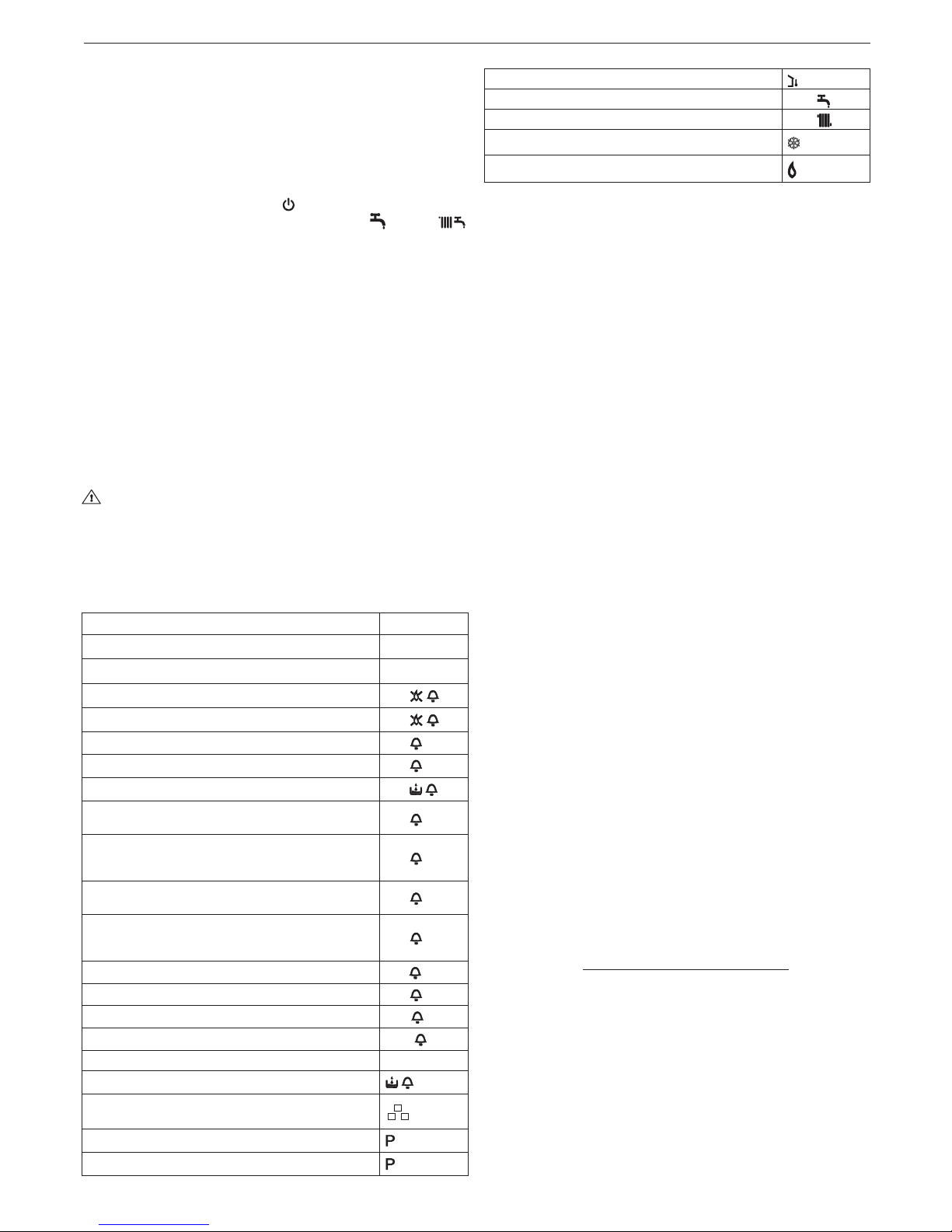
30
Mynute Green C.S.I. E - R.S.I. E
Anomalie A06
La chaudière fonctionne normalement, mais ne garantit pas la stabilité
de la température de l'eau sanitaire, qui reste réglée autour d'une tem-
pérature de 50 °C. Demander l’intervention du Service après-vente.
Anomalie A07
Demander l’intervention du Service après-vente.
Anomalie A08
Demander l’intervention du Service après-vente.
Anomalie A09
Placer le sélecteur de fonction sur éteint (OFF), attendre 5-6 se-
condes puis le mettre dans la position souhaitée (été) ou
(hiver). Si les tentatives de déblocage ne réactivent pas la chaudière,
demander l’intervention du Service Après-vente.
Anomalie A09
La chaudière est équipée d'un système d'auto-diagnostic qui, sur la
base du nombre total d'heures dans certaines conditions de fonctionne-
ment, peut signaler la nécessité de nettoyer l'échangeur primaire (code
alarme 09 et dispositif de mesure des gaz de combustion >2 500).
Une fois le nettoyage terminé, remettre à zéro le compteur horaire
avec le kit spécial fourni en observant la procédure suivante:
- éteindre l'alimentation
- enlever la coque
- en tournant le panneau de commande vers soi
- dévisser les deux vis du petit capot de la carte électronique pour
accéder aux bornes
- tandis que la chaudière est alimentée, en utilisant un petit tournevis inclus, appuyer sur le bouton CO (g. 8) pendant au moins 4
secondes, pour vérier que le débitmètre a été réinitialisé, éteindre
puis rallumer la chaudière; la lecture du débitmètre est visualisée sur
l'afcheur après le symbole “-C-”.
Parties électriques sous tension (230 V AC).
REMARQUE: la procédure de remise à zéro du compteur doit être
réalisée après chaque nettoyage en profondeur de l'échangeur primai-
re ou si ce dernier est remplacé. Pour contrôler l'état du compteur,
multiplier la lecture par 100 (ex. lecture de 18 = 1800 heures; lecture
de 1 = 100 heures).
La chaudière continue à fonctionner normalement même lorsque l'alarme est activée.
ÉTAT DE LA CHAUDIÈRE AFFICHEUR
Stand-by -
État OFF OFF
Alarme de verrouillage du module ACF
A01
Alarme de panne électrique ACF
A01
Alarme de thermostat limite
A02
Alarme tacho ventilateur
A03
H2O alarme de pressostat
A04
Panne d'eau sanitaire NTC (R.S.I uniquement avec un
chauffage à stockage extérieur avec sonde)
A06
Panne de thermistance (de ux) primaire - Surchauffe
de la thermistance (de ux) primaire - Différentiel de
température
A07
Panne de thermistance de retour - Surchauffe de
thermistance de retour - Différentiel de température inversé
A08
Panne de Thermistance de combustion ou de compteur
de thermistance de combustion Surchauffe thermistance de combustion
A09
Fausse amme
A11
Panne de thermostat à basse température
A77
Réglage
ADJ
Fonctionnement de service
ACO
Transitoire en attente d'allumage 88°C clignotant
H2O intervention du pressostat
clignotant
Mode cycle de purge actif
Fonction de préchauffage active (uniquement C.S.I.)
Demande de préchauffage (uniquement C.S.I.)
clignotant
Sonde extérieure présente
Demande de chauffage eau sanitaire 60°C
Demande de chauffage 80°C
Demande de chaleur antigel
Flamme présente
4.5 Conguration de la chaudière (g. 19)
La carte électronique contient une série de cavaliers (JP4) qui peuvent
être utilisés pour configurer la chaudière.
Pour accéder à la carte, procéder comme suit:
- éteindre l'alimentation
- enlever la coque
- en tournant le panneau de commande vers soi
- dévisser les deux vis du petit capot de la carte électronique pour
accéder aux bornes.
CAVALIER JP7:
plage de réglage de présélection de la température de chauffage la
plus adaptée en fonction du type d'installation.
Cavalier non inséré - installation standard
Installation standard 40-80°C
Cavalier inséré - installation au sol
Installation au sol 20-45°C.
Au cours de la fabrication, la chaudière est congurée pour les installations standard.
JP1 Réglage (Range Rated)
JP2 Réinitialisation minuterie de chauffage
JP3 Réglage (voir paragraphe “Réglages”)
JP4 Sélecteur de thermostat d'eau chaude sanitaire absolu (modèle C.S.I.)
JP4 Ne pas utiliser (modèle R.S.I.)
JP5 Ne pas utiliser (modèle C.S.I.)
JP5 Fonction chauffage uniquement avec une prédisposition pour un
réservoir de stockage extérieur avec thermostat (JP8 inséré) ou
une sonde (JP8 non inséré) (modèle R.S.I.)
JP6 Activation de fonction de compensation de nuit et pompe conti-
nue (uniquement avec le capteur extérieur branché)
JP7 Activation de la gestion des installations à basse température/
standard (voir ci-dessus)
JP8 Ne pas utiliser (modèle C.S.I.)
JP8 Gestion d'un réservoir de stockage extérieur avec thermostat ac-
tivé (cavalier inséré)/gestion d'un réservoir de stockage extérieur
avec sonde (cavaliers non insérés) (modèle R.S.I.).
4.6 Conguration de la régulation thermique (gra-
phiques 1-2-3 g. 20)
La régulation thermique fonctionne uniquement lorsque le capteur extérieur est branché; une fois installé, brancher le capteur extérieur (accessoire disponible sur demande) aux bornes spéciales situées sur le
bornier de la chaudière.
Cela active la fonction THERMORÉGULATION.
Sélection de la courbe de compensation
La courbe de compensation du chauffage maintient une température
théorique de 20 °C dans la pièce pour des températures extérieures
comprises entre +20 °C et –20 °C. Le choix de la courbe dépend de la
température extérieure minimale envisagée (et donc de la localisation
géographique) et de la température de refoulement envisagée (et donc
du type d'installation). La courbe doit alors être calculée attentivement
par l'installateur selon la formule suivante:
T. de refoulement envisagée - Tshift
KT=
Temp. extérieure envisagée min. 20-
Tshift = 30°C installations standard
25°C installations au sol
Si le calcul produit une valeur intermédiaire entre deux courbes, il est
conseillé de choisir la courbe de compensation la plus proche de la
valeur obtenue.
Exemple: si la valeur obtenue par le calcul est de 1,3, c'est entre la
courbe 1 et la courbe 1,5. Choisir la courbe la plus proche, à savoir 1,5.
Sélectionner le KT à l'aide du trimmer P3 sur la carte (voir schéma de
câblage multiple).
Pour accéder à P3:
- éteindre l'alimentation
- enlever la coque
- en tournant le panneau de commande vers soi
 Loading...