

Beretta Mynute Green E 25 C.S.I., Mynute Green E 30 C.S.I. Installer And User Manual

Installer and user manual
My
nute Green E 25 C.S.I. 30 C.S.
I.
EN
INSTALLER AND USER MANUAL
ES
MANUAL PARA EL INSTALADOR Y EL
USUARIO

Mynute Green E C.S.I.
2
EN
ES
0476
0063CQ3187
0476
0063CQ3187
Mynute Green E C.S.I. boiler complies with basic requirements of the
following Directives:
- Gas directive 2009/142/EC;
- Yield directive 92/42/EEC;
- Electromagnetic compatibility directive 2004/108/EC;
- Low-voltage directive 2006/95/EC;
- Directive 2009/125/EC Ecodesign for energy-using appliances;
- Directive 2010/30/EU Indication by labelling of the consumption of energy
by energy-related products;
- Delegated Regulation (EU) No. 811/2013;
- Delegated Regulation (EU) No. 813/2013;
- Delegated Regulation (EU) No. 814/2013.
Thus, it is EC-marked.
La caldera Mynute Green E C.S.I. boiler cumple con los requisitos básicos
de las siguientes Directivas:
- Directiva Gas 2009/142/CE;
- Directiva rendimiento 92/42/CEE;
- Directiva compatibilidad electromagnética 2004/108/CE;
- Directiva baja tensión 2006/95/CE;
- Directiva 2009/125/CE Diseño ecológico para aparatos que consumen
energía;
- Directiva 2010/30/UE Indicación mediante etiquetado del consumo
energético de productos relacionados con la energía;
- Reglamento Delegado (UE) N.º 811/2013;
- Reglamento Delegado (UE) N.º 813/2013;
- Reglamento Delegado (UE) N.º 814/2013.
Por lo tanto, tiene el marcado CE.
Installer – User Manual...............................................................3
Technical data..................................................................... 20-23
Overall dimensions and fi ttings.................................................46
Hydraulic circuit ........................................................................46
Command panel .......................................................................47
Boiler functional elements ........................................................48
Multi-row wiring diagram...........................................................49
Manual Instalador – Usuario.....................................................24
Datos técnicos .................................................................... 41-44
Dimensiones y conexiones .......................................................46
Circuito hidráulico .....................................................................46
Panel de mandos......................................................................47
Elementos funcionales de la caldera ........................................48
Esquema eléctrico con cableado múltiple ................................49
The following symbols are used in this manual:
CAUTION = operations requiring special care and adequate
preparation
NOT ALLOWED = operations that MUST NOT be performed
En algunas partes del manual se utilizan los símbolos:
ATENCIÓN = para acciones que requieren particular atención
y una adecuada preparación
PROHIBIDO = para acciones que NO DEBEN efectuarse
nunca

Mynute Green E C.S.I.
3
EN
INSTALLER
1 - WARNINGS AND SAFETY
Our boilers are built in our plants and checked down to the
smallest detail in order to protect users and fitters from injury.
After working on the product, qualified personnel must check
the electrical wiring, in particular the stripped part of conductors, which must not stick out from the terminal board, avoiding
possible contact with live parts of such conductor.
This instruction manual, together with the user manual, are in-
tegral parts of the product: make sure that they are always kept
with the appliance, even if it is transferred to another owner or
user, or moved to another heating system. In case of loss or
damage, please contact your local Technical Assistance Service for a new copy.
The boiler must only be installed and serviced by qualified per-
sonnel, in accordance with Ministerial Decree 37 of 2008 and
Standards UNI-CIG 7129-7131, UNI 11071 and subsequent
updates.
Boiler maintenance must be carried out at least once a year.
This should be booked in advance with the Technical Assistance Service.
The installer must instruct the user about the operation of the
appliance and essential safety requirements.
This boiler must only be used for the application it was de-
signed for. The manufacturer declines all contractual and
non-contractual liability for injury to persons or animals or damage to property deriving from errors made during installation,
adjustment and maintenance and from improper use.
After removing the packaging, make sure the content is in good
condition and complete. Otherwise, contact the dealer from
whom you purchased the appliance.
The appliance's discharge manifold must be connected to a
suitable venting system. The manufacturer of the appliance is
not liable for any damage/flooding resulting from the failure of
the channel system.
Dispose of all the packaging materials in the appropriate con-
tainers c/o specific collection centres.
Dispose of waste taking care not to harm human health and
without employing procedures or methods which may damage
the environment.
At the end of its life, the product should be not be disposed of
as solid urban waste, but rather it should be handed over to a
differentiated waste collection centre.
During installation, inform the user that:
- in the event of water leaks, the water supply must be shut
off and the Technical Assistance Service must be contacted
immediately
- regularly check that the operating pressure of the hydraulic
system is greater than 1 bar. If necessary, restore the pressure as explained in the “System filling” section
- if the boiler has not been used for a long time, it is recom-
mended that the Technical Assistance Service performs, at
least, the following operations:
- turn the main switch of the appliance and the main switch
of the system to "off"
- Close the fuel and water taps of the heating system
- drain the heating circuit to prevent freezing.
For safety, always remember that:
the boiler should not be used by children or unassisted disa-
bled people
it is dangerous to operate electrical devices or appliances
(such as switches, home appliances, etc.) if you smell gas or
combustion fumes. In the event of gas leaks, ventilate the room
opening doors and windows; close the gas general tap; request
prompt action by Technical Assistance Service professionally
qualified personnel
do not touch the boiler while barefoot, or if parts of your body
are wet or damp
set the function selector switch to OFF/RESET to bring up “- -”
on the display, then disconnect the boiler from the main power
supply by turning off the main system switch before carrying
out any cleaning operations
do not modify safety and adjustment devices without the man-
ufacturer's permission and relative instructions
do not pull, disconnect or twist the electric cables coming out
of the boiler, even when it is disconnected from the main power
supply
avoid covering or reducing the size of the ventilation openings
in the installation room
do not leave inflammable containers and substances in the in-
stallation room
keep packaging materials out of the reach of children
it is forbidden to obstruct the condensate drainage point.
2 - DESCRIPTION
Mynute Green E C.S.I. is a wall-mounted type C condensation boil-
er for heating and the production of domestic hot water. Depending
on the fume discharge accessory used, it is classified in categories
B23P; B53P; C13, C13x; C23; C33, C33x; C43, C43x; C53, C53x;
C63, C63x; C83, C83x; C93, C93x.
In configuration B23P (when installed indoors), the appliance cannot
be installed in bedrooms, bathrooms, showers or where there are
open fireplaces without a proper air flow. The room where the boiler
is installed must have proper ventilation. Detailed regulations for the
installation of the flue, gas piping and ventilation ducting are given in
Standards UNI-CIG 7129-7131 and UNI 11071.
In configuration C, the appliance can be installed in any type of room
and there are no limitations due to ventilation conditions or room volume.
IT IS also possible, using a check valve included as an accessory, to
install the boiler on collective pressurised flues; for the details, see
section 3.10 “Installation on collective flues in positive pressure”.
The main technical characteristics of the appliance are:
- digital display indicating the operating temperature and alarm
codes
- pre-mix, low emissions burner
- air-gas ratio adjustment system with pneumatic management
- microprocessor card to control inputs, outputs and alarm management
- continuous electronic flame modulation for domestic hot water and
heating
- electronic ignition with flame ionisation control
- fan controlled by Hall-effect revolutions counter
- built-in gas pressure stabiliser
- NTC probe to control delivery temperature of the primary circuit
- NTC probe to control return temperature of the primary circuit
- built in NTC integrated probe to control domestic hot water temperature
- dual device for separation and automatic purging of air
- automatic heating circuit by-pass

ENGLISH
4
- 3-way valve with electric actuator
- heat exchanger for DHW preparation in brazed stainless steel with
anti-limescale device
- expansion tank
- low consumption modulating circulator
- manual loading of the heating circuit
- water pressure switch
- hydrometer to visualise heating water pressure
- circulator anti-blocking device
- airtight combustion chamber
- electrically operated gas valve with dual shutter to command the
burner
- domestic hot water heat exchanger pre-heating function to reduce
domestic hot water standby times
- self-diagnostics for signalling the cleaning of the primary circuit
heat exchanger.
The safety devices of the appliance are:
- a water limit thermostat, to check for any overheating of the appliance and thereby ensure the 100% safety of the system. To restore
operation if a limit thermostat has been triggered, set the function
selector to OFF/RESET and then return it to the desired position
- flue gas probe: this intervenes (putting the boiler in safety stop
mode) if the temperature of the combustion products exceeds the
maximum operating temperature of the discharge pipes
- 3 bar safety valve on the heating circuit
- a microprocessor check of probe continuity, with any faults indicated on the display
- a syphon with float, for discharging the condensate and preventing
the leakage of flue gases
- a condensate level sensor that operates by blocking the boiler if
the level of condensate in the heat exchanger exceeds the allowed
limit
- first level anti-freeze function (suitable for indoor installations)
which also operates with the boiler in standby and which is activated when the water temperature falls below 6°C
- diagnosis for absence of circulation (via the display of the temperatures read by the delivery and return probes)
- diagnosis for absence of water (via the water pressure switch)
- a flue gas safety evacuation system incorporated in the pneumatic
operation of the gas valve
- diagnosis for overtemperature on both the delivery and return
lines, with dual probe - limit temperature 95°C -
- high modulation, the boiler can automatically modulate the output
power in a maximum and minimum range (see technical data)
The boiler is installation ready for the following:
- a safety thermostat for reduced temperature systems
- an ambient thermostat or hourly timer
- connection to remote control with related alarm signalling.
3 - INSTALLATION
3.1 Installation regulations
Installation must be carried out by qualified personnel in compliance
with local regulations.
POSITION
Mynute Green E C.S.I. is a wall-mounted boiler for heating and for
the production of hot water. There are two categories, depending on
the type of installation:
1. B23P-B53P type boiler - forced open installation, with flue gas
discharge pipe and pick-up of combustion air from the installation area. If the boiler is not installed outdoors, air intake in the
installation area is compulsory.
2. C13, C13x type boiler; C23; C33, C33x; C43, C43x; C53, C53x;
C63, C63x; C83, C83x, C93, C93x: appliance with airtight chamber, with flue gas discharge pipe and pick-up of combustion air
from outside.
It does not require an air intake point in the installation area.
This type MUST be installed using concentric pipes, or other
types of discharge designed for condensation boilers with an airtight chamber.
MINIMUM DISTANCES
In order to have access to the boiler to perform regular maintenance
operations, respect the minimum spaces foreseen for installation
(fig. 1).
For correct appliance positioning:
- do not place it on a cooker or other cooking device
- do not leave inflammable products in the room where the boiler is
installed
- heat sensitive walls (for example, wooden walls) must be protected
with proper insulation.
IMPORTANT
Before installation, wash every system piping carefully in order to
remove any residues that may impair the operation of the appliance.
Connect the discharge manifold to a suitable discharge system (for
details, refer to chapter 3.6). The domestic hot water circuit does not
need a safety valve, but make sure that the pressure of waterworks
does not exceed 6 bar. In case of doubts, install a pressure reducer.
Prior to ignition, make sure that the boiler is designed to operate with
the gas available; this can be checked by the wording on the packaging and by the adhesive label indicating the gas type.
It is very important to highlight that in some cases the smoke pipes
are under pressure and therefore, the connections of several elements must be airtight.
3.2 Cleaning the system / characteristics of the heating
circuit water
In the case of a new installation or replacement of the boiler, it is
necessary to clean the heating system.
To ensure the device works well, top up the additives and/or chemical
treatments (e.g. anti-freeze liquids, filming agents, etc.) and check
the parameters in the table are within the values indicated.
Parameters Um
Heating
circuit water
Filling water
PH value 7~8 -
Hardness ° F - 15~20
Appearance - clear

Mynute Green E C.S.I.
5
3.3 Eliminating the air from the heating circuit and boiler
During the initial installation phase, or in the event of extraordinary
maintenance, you are advised to perform the following sequence of
operations (Fig. 2):
1. Open by two or three turns the automatic relief valve cap (A) and
leave it open.
2. Open the system filling tap located on the water unit.
3. Switch on the electricity supply to the boiler, leaving the gas tap
turned off.
4. Activate a heat request via the ambient thermostat or the remote
control panel, so that the 3-way valve goes into heating mode.
5. Activate a domestic water request as follows: open a tap for 30”
every minute so the 3-way valve passes from heating to domestic water and vice versa about 10 times. In this situation, the
boiler will go into alarm mode due to the absence of gas, so it
must be reset every time this happens).
6. Continue the sequence until no more air can be heard coming
from the air vent valve.
7. Check the system pressure level is correct (the ideal level is 1
bar).
8. Turn off the system filling tap.
9. Turn on the gas tap and ignite the boiler.
3.4 Positioning the wall-mounted boiler and hydraulic
connections
The boiler is supplied as standard with a boiler support plate with
built-in pre-assembly template (Fig. 3). The position and dimension
of hydraulic fittings are shown in the detail drawing.
For the assembly, proceed as follows:
- secure the boiler support plate (F) using the pre-assembly template
(G) to the wall and use a spirit level to make sure that everything
is perfectly horizontal
- mark the 4 holes (ø 6 mm) envisaged for securing the boiler sup-
port plate (F) and the 2 holes (ø 4 mm) for securing the pre-assembly template (G)
- make sure that all measurements are exact, then drill the wall us-
ing drill tips with the diameters indicated above
- fix the plate with the built-in template to the wall.
Make the hydraulic connections.
The position and size of the hydraulic connections are indicated below:
R heating return line 3/4” M
M heating delivery 3/4” M
G gas connection 3/4” M
AC hot water 1/2” M
AF cold water 1/2” M
3.5 Installing the external probe
The correct operation of the external probe, supplied as an accessory, is fundamental for the good operation of the climatic control.
INSTALLING AND CONNECTING THE EXTERNAL PROBE
The probe must be installed on an external wall of the building to be
heated, observing the following indications:
- it must be mounted on the side of the building most often exposed
to winds (the NORTH or NORTHWEST facing wall), avoiding direct
solar irradiation;
- it must be mounted about 2/3 of the way up the wall;
- it must not be mounted near doors, windows, air outlet points, or
near smoke pipes or other heat sources.
The electrical wiring to the external probe is made with a bipolar cable with a section from 0.5 to 1 mm2 (not supplied), with a maximum
length of 30 metres. It is not necessary to respect the polarity of the
cable when connecting it to the external probe. Avoid making any
joints on this cable however; if joints are absolutely necessary, they
must be watertight and well protected.
Any ducting of the connection cable must be separated from live cables (230V AC)
FIXING THE EXTERNAL PROBE TO THE WALL
The probe must be placed on a smooth part of the wall (Fig. 4); in the
case of exposed brickwork or an uneven wall, look for the smoothest
possible area. Loosen the plastic upper protective cover by turning
it anticlockwise.
After deciding on the best fixing area of the wall, drill the holes for the
5x25 wall plug.
Insert the plug in the hole. Remove the card from its seat.
Fix the box to the wall, using the screw supplied.
Attach the bracket, then tighten the screw.
Loosen the nut of the cable grommet, then insert the probe connection cable and connect it to the electric clamp.
To make the electrical connection between the external probe and
the boiler, refer to the “Electrical wiring” chapter.
Remember to close the cable grommet well, to prevent any air
humidity getting in through the opening.
Put the card back in its seat.
Close the plastic upper protective cover by turning it clockwise. Tighten the cable grommet very well.
3.6 Condensate collection
The discharge manifold (Fig. 5) collects condensate water, any evacuation water from the safety valve and the system discharge water.
The manifold must be connected via a rubber pipe (not provid-
ed) to an appropriate collection and evacuation system in the
white water discharge drain in compliance with current regulations. The outer diameter of the manifold is 20 mm: it is therefore advisable to use a rubber pipe Ø 18-19 mm closed with a
suitable clamp (not provided).
The manufacturer is not liable for any damage/flooding result-
ing from the failure to channel the condensate.
Sealing of the condensate drainage connection line must be
guaranteed.
3.7 Electrical wiring
To access the electrical wirings, proceed as follows:
To access the terminal board:
- set the system's main switch to off
- undo the fixing screws (A) of the shell (fig. 6)
- move the shell base forward and then upwards to unhook it from
the chassis
- lift and then turn the instrument panel upside down (fig. 7)
- remove the electrical parts inspection cover (fig. 8)
The connection to the mains supply must be made via a separation
device with an omnipolar opening of at least 3.5 mm (EN 60335/1,
category 3).
The appliance operates with an alternating current of 230 Volt/50 Hz
and complies with the standard EN 60335-1.
It is obligatory to make the connection with a safe ground/earth,
in compliance with current directives.
The installer is responsible for ensuring the appliance is suita-
bly earthed; the manufacturer will not be liable for any damage
resulting from an incorrect or absent earth connection
It is also advisable to respect the phase-neutral connection
(L-N).
The ground/earth wire must be a couple of cm longer than the
others.
The boiler can operate with a phase-neutral or phase-phase supply.
For power supplies that are not earthed, it is necessary to use an
isolating transformer with earth-anchored secondary.
It is forbidden to use gas and/or water pipes to earth electrical appliances.
Use the power cable supplied to connect the boiler to the mains power supply.
If the power cable needs to be replaced, use a cable of the HAR
H05V2V2-F type, 3 x 0.75 mm², with a maximum external diameter
of 7 mm (fig. 9).
ENGLISH
6
3.8 Gas connection
Before connecting the appliance to the gas network, check that:
- current prevailing standards have been met
- the gas type is appropriate for the appliance
- the piping is clean.
The gas pipe must be installed outdoors. If the pipe has to pass
through the wall, it must pass through the central opening in the lower part of the template.
It is advisable to install a filter of suitable dimensions on the gas line
if the distribution network contains solid particles.
Once the appliance has been installed, check the connections are
sealed according to current installation regulations.
3.9 Flue gas exhaustion and air aspiration (fig. 10)
For flue gas discharge, refer to Standards UNI-CIG 7129-7131 and
UNI 11071. Always comply with local standards of the Fire Department, the Gas Company and with possible municipal dispositions.
The discharge of flue gas is guaranteed by the centrifugal fan located
inside the combustion chamber. The boiler is supplied without the
flue gas outlet/air suction kit, since it is possible to use the accessories for appliance with a forced draught sealed chamber that better
adapts to the installation characteristics.
It is essential for evacuating fumes and restoring boiler combustion
air that only original Riello pipes be used and that the connection is
made correctly as shown in the instructions provided with the flue
gas accessories.
A single smoke pipe can be connected to several appliances provided that every appliance is the condensing type
The boiler is a C-type appliance (with airtight chamber), and must
therefore have a safe connection to the flue gas discharge pipe and
to the combustion air suction pipe; these both carry their contents
outside, and are essential for the operation of the appliance.
Both concentric and twin terminals are available.
As envisaged by Standard UNI 11071, the boiler is designed to take
in and dispose of flue gas condensate and/or meteoric water condensate deriving from the flue gas discharge system. It does this via its
own drain-tap, if an external drain-tap is not fitted during the design
or installation phase.
if a condensate relaunch pump is installed, check the technical
data (provided by the manufacturer) regarding output, to ensure it operates correctly.
POSSIBLE OUTLET CONFIGURATIONS (fig. 11)
B23P-B53P - Suction in room, with external outlet.
C13-C13x - Concentric wall outlet. Pipes can leave the boiler inde-
pendently, but the outputs must be concentric or near enough in order to be subjected to similar wind conditions (within 50 cm).
C23 - Concentric outlet in regular smoke pipe (suction and outlet in
the same pipe).
C33-C33x - Concentric roof outlet. Output as C13.
C43-C43x - Discharge and suction in common, separate smoke
pipes, but subjected to similar wind conditions.
C53-C53x - Separate wall or roof outlet and suction line and in areas
with different pressures. Outlet and suction line must never be placed
on opposite walls.
C63-C63x - Outlet and suction line carried out with pipes marketed
and certified separately (1856/1).
C83-C83x - Outlet in single or regular smoke pipe and wall suction
line.
C93-C93x - Discharge on the roof (similar to C33) and air suction
from a single existing smoke pipe.
See the prevailing standards.
“FORCED OPEN” INSTALLATION (TYPE B23P/B53P)
Flue gas discharge pipe ø 80 mm (fig. 12)
The flue gas outlet pipe can be directed to the most suitable direction
according to installation requirements. For installation, follow the instructions supplied with the kit.
In this configuration, the boiler is connected to the flue gas outlet pipe
of ø 80 mm through an adaptor of ø 60-80 mm.
In this case, the combustion air is picked up from the boiler
installation room (which must be a suitable technical room with
proper ventilation).
The non insulated flue gas outlet pipes are potential sources of
danger.
Arrange the flue gas discharge pipe so it slopes by 3° towards
the boiler.
The boiler automatically adapts the purging to the type of in-
stallation and the length of the pipe.
Maximum length of the flue gas
discharge pipe Ø 80 mm
Pressure loss
45° curve 90° curve
25 C.S.I. 80 m
1 m 1.5 m
30 C.S.I. 80 m
“AIRTIGHT” INSTALLATION (TYPE C)
The boiler must be connected to concentric or twin flue gas discharge
pipes and air suction pipes, both leading outdoors. The boiler must
not be operated without them.
Concentric pipes (Ø 60-100 mm) (Fig. 13)
The concentric pipes can be fitted in most suitable direction in relation to installation requirements complying with the maximum lengths
show on the table.
Arrange the flue gas discharge pipe so it slopes by 3° towards
the boiler.
Non-insulated outlet pipes are potential sources of danger.
The boiler automatically adapts the purging to the type of in-
stallation and the length of the pipe.
Do not obstruct or choke the combustion air suction pipe in any
way.
For installation, follow the instructions supplied with the kit.
Horizontal
Max straight length of concentric
pipe Ø 60-100 mm
Pressure loss
45° curve 90° curve
25 C.S.I. 7.85 m
1.3 m 1.6 m
30 C.S.I. 7.85 m
Vertical
Max straight length of concentric
pipe Ø 60-100 mm
Pressure loss
45° curve 90° curve
25 C.S.I. 8.85 m
1.3 m 1.6 m
30 C.S.I. 8.85 m
"Straight length" means without bends, drainage terminals or
joints.
Concentric pipes (Ø 80-125 mm) (Fig. 14)
For this configuration the specific adaptor kit must be installed. The
concentric pipes can be fitted in most suitable direction in relation
to installation requirements. For installation, follow the instructions
supplied with the specific kits for condensing boilers.
Maximum straight length of
concentric pipe Ø 80-125 mm
Pressure loss
45° curve 90° curve
25 C.S.I. 14.85 m
1 m 1.5 m
30 C.S.I. 14.85 m
"Straight length" means without bends, drainage terminals or
joints.

Mynute Green E C.S.I.
7
Twin pipes (Ø 80 mm) (Fig. 15)
The twin pipes can face in the direction most suitable for installation
requirements.
For installation, follow the instructions supplied with the specific accessory kit for condensation boilers.
Arrange the flue gas discharge pipe so it slopes by 3° towards
the boiler.
The boiler automatically adapts the purging to the type of in-
stallation and the length of the pipes. Do not obstruct or choke
the pipes in any way.
For the maximum length indications of the individual pipe see
the graphics (fig. 16).
The use of longer pipes reduces the boiler output.
Maximum straight length
of twin pipe Ø 80 mm
Pressure loss
45° curve 90° curve
25 C.S.I. 53+53 m
1 m 1.5 m
30 C.S.I. 42+42 m
Ø 80 twin pipes with Ø 50 and 60 pipework (Fig. 17)
The characteristics of the boiler allow the Ø 80 flue gas discharge
pipe to be connected to the Ø 50 or 60 range of pipework.
For the pipework we recommend carrying out a design calcula-
tion in order to comply with the applicable prevailing standards.
The allowed base configurations are indicated in the table.
Base pipe configuration table (*)
Air suction 1 90° ø 80 curve
4.5 m ø 80 pipe
Flue gas exhaust 1 90° ø 80 curve
4.5 m ø 80 pipe
Reductio
n from ø 80 to ø 50 or ø 80 to ø 60
flue base curve 90° ø 50 or ø 60
for pipework pipe lengths see the table
(*) Use the plastic (PP) flue accessory systems for condensing boilers that can be found on the residential catalogue price list, ø 50 H1
class and ø 60 P1 class
The boilers come from the factory calibrated to:
- 25 C.S.I.: 4,700 r.p.m. and maximum length reachable is 11 m for
the ø 60 pipe and
1 m for the ø 50 pipe
- 30 C.S.I.: 5,600 r.p.m. and maximum length reachable is 14 m for
the ø 60 pipe and
2 m for the ø 50 pipe
If you need to reach greater lengths compensate for the pressure
drop with an increase of the number of fan rotations as shown in the
adjustments table in order to guarantee the rated heat input.
The minimum calibration must not be modified.
If the prevailing value is greater than 200 Pa the law requires the use
of H1 pressure class flue accessories
Mynute Green E 25 C.S.I. adjustments table
Maximum number
of fan rotations
(rpm)
Ø 50 pipework pipes
maximum length
Ø 60 pipework pipes
maximum length
ΔP at the boiler
output with
max length (°)
DHW CH
mmPA
4700 3900 1
11 9 0
4800 4000 4
16 120
4900 4100 6
22 150
5000 4200 8
28 180
5100 4300 10
31 (*) 200
5200 4400 14
- 255
5300 4500 17
- 295
5400 4600 20
- 338
5500 4700 23
- 375
5600 4800 26
- 410
5700 4900 28
- 445
5800 5000 32
- 485
5900 5100 35
- 535
6000 5200 38
- 575
6100 5300 41
- 613
6200 5400 44
650
Maximum number
of fan rotations
(rpm)
Ø 50 pipework pipes
maximum length
Ø 60 pipework pipes
maximum length
ΔP at the boiler
output with
max length (°)
DHW CH
mmPA
6300 5500 49
710
Mynute Green E 30 C.S.I. adjustments table
Fan rotations
maximum number
of fan rotations
(rpm)
Ø 50 pipework
pipes
Maximum length
Ø 60 pipework pipes
Maximum length
ΔP at the
boiler output
with max
length (°
)
DHW CH
mmPa
5600 4700 2
14 145
5700 4800 4
19 183
5800 4900 5
21 (*) 200
5900 5000 8
- 255
6000 5100 11
- 295
6100 5200 13
- 330
6200 5300 15 377
6300 5400 19 440
(*) Compatible length with P1 class pipes
NOTE
If p
ipes different than those in the Beretta catalogue are used you must
see the ΔP values on the above tables to calculate the maximum length
of the pipes.
The Ø 60 and Ø 50 configurations have experimental, laboratory checked
data.
In the event of installations other than those indicated in the “base
configurations” and “adjustments” table, see the equivalent Ø 80 - Ø
60 or Ø 50 linear lengths shown below.
In any case the maximum lengths declared in the booklet are
guaranteed and it is essential that they are not exceeded.
Ø 60 component
Linear equivalent in
metres Ø 80 (m)
45° Ø 60 curve 5
90° Ø 60 curve 8
0.5 m Ø 60 extension 2.5
1.0 m Ø 60 extension 5.5
2.0 m Ø 60 extension 12
Ø 50 COMPONENT Linear equivalent in
metres Ø 80 (m)
45° Ø 50 curve
12,3
90° Ø 50 curve 19,6
0.5 m Ø 50 extension 6,1
1.0 m Ø 50 extension 13,5
2.0 m Ø 560 extension 29,5
3.11 Installation on collective flues in positive pressure
The collective flue is a gas discharge system suitable for collecting
and expelling the combustion products of several appliances installed on several floors of a building (fig. 18).
The collective flues in positive pressure can be used only for type C
condensing appliances. Consequently the B53P/B23P configuration
is not permitted.
Installation of the boiler on collective flues in pressure is permitted
only at G20 using a specific check valve, supplied as an accessory.
See the related instructions for the assembly procedure.
The boiler is sized to operate correctly up to a maximum internal
pressure of the smoke pipe no higher than the value shown in the
multigas table.
Complete the check valve assembly operations and proceed with
adjustment of the number of fan rotations as shown in the multigas
table.
Ensure that the air suction pipes and combustion product outlet are
airtight.
Installation of the check valve (fig. 19) requires the application of the
ATTENTION label that comes with the same accessory on a visible
part of the boiler shell. Applying the label is essential for safety during
maintenance or replacement of the boiler and/or the collective flue.

ENGLISH
8
WARNINGS
The manufacturer will not be liable in the event of failure to
apply the check valve and the related label prior to placing the
boiler in service.
The appliances connected to a collected flue must all be of the
same type and have equivalent combustion characteristics.
The number of appliances that can be connected to a collective
flue in positive pressure is defined by the smoke pipe designer.
MAINTENANCE FOR APPLICATION IN A COLLECTIVE FLUE
UNDER PRESSURE
During scheduled maintenance on the appliance you must also
check the condition of the check valve in order to guarantee correct
operation and safety of the system.
Before proceeding with maintenance you must conduct an analysis
of the combustion product and check the boiler operating status.
In the event of maintenance on the boiler's combustion circuit
(gas discharge pipes, condensate syphon, burner, electrode
conveyors) you must close the gas discharge pipe that comes
from the smoke pipe under pressure and check the seal.
Subsequently:
- Remove electrical power by setting the system's main switch to
“off”
- Close the gas interception taps
- Remove the shell
- Unhook the instrument panel and rotate it downward
- Unhook and remove the air box cover
- After undoing the related fixing screws, remove the right side of
the air box
- Undo the nut that secures the gas train valve to the air box
- Undo and remove the mixer connection gas train (A, fig. 20)
- Remove the ignition electrode and flame detection electrical connections and the fan electrical connections
- Undo the 4 screws that secure the air gas conveyor to the main
heat exchanger (B, fig. 20)
- Remove the conveyor-fan assembly from the heat exchanger (C,
fig. 20), taking great care not to damage the burner insulating panel
- To access the check valve remove the fan by undoing the 4 screws
(D, fig. 21) that secure it to the conveyor
- Ensure that there is no material deposited on the check valve
membrane and remove any you may find, ensuring there is no
damage.
- Check the correct opening and closing operation of the valve
- Reassemble the components working in reverse order, ensuring
that the check valve is reassembled in the correct direction (see
fig. 21)
Failure to observe the above may lead to abnormal operation
of the check valve and consequent differences in the boiler's
performance, up to failure to operate.
Failure to observe what is described here may compromise the
safety of people and animals due to possible carbon monoxide
leaks from the smoke pipe.
Once the operations have been completed, carefully check
all the combustion product exhaust and air suction pipe seals,
conducting a combustion analysis.
NOTE
If the fan is removed ensure that the check valve is reassembled in
the correct direction (see fig. 21).
3.12 Filling the heating system
Once the hydraulic connections have been carried out, fill the heating
system.
This operation must be carried out with a cold system, following
these instructions (fig. 22):
- open the lower automatic relief valve cap (A) by two or three turns
to allow continuous air venting and leave it open
- ensure that the cold water inlet tap is open
- open the filling tap (C) until the pressure indicated on the water
gauge is between 1 bar and 1.5 bar (fig. 23)
- re-close the filling tap.
NOTE
deareation of the boiler takes place automatically by means of the
two automatic A and E bleed valves (fig. 24), the former positioned
on the circulator whereas the latter is positioned inside the air box. If
the deareation phase is difficult, operate as described in section 5.3.
3.13 Emptying the heating system
Before starting emptying, switch off the electricity supply by turning
off the main switch of the system.
- Close the heating system shut-off devices
- Slacken the discharge system valve by hand (D)
- The system's water is discharged through the discharge manifold
(F).
The discharge manifold must be connected via a rubber pipe
to an appropriate collection and evacuation system in the white
water discharge drain in compliance with current regulations.
The outer diameter of the manifold is 20 mm: it is therefore advisable to use a rubber pipe Ø18-19 mm closed with a suitable
clamp (not provided).
3.14 Emptying the domestic hot water circuit
When there is risk of frost, the domestic hot water system must be
emptied in the following way:
- close the water mains tap
- open all the hot and cold water taps
- empty the lowest points.
4 - IGNITION AND OPERATION
4.1 Preliminary checks
First ignition is carried out by competent personnel from an authorised Technical Assistance Service Centre.
Before starting up the boiler, check:
a) that the supply networks data (electric, water, gas) corresponds
to the label data
b) that piping leaving the boiler is covered by thermal insulation
sheath
c) that flue gas extraction and air suction pipes work correctly
d) that conditions for regular maintenance are guaranteed if the
boiler is placed inside or between furniture
e) the seal of the fuel adduction system
f) that fuel capacity corresponds to values requested by the boiler
g) the correct calibration of the gas valve and, if necessary, adjust
as indicated in paragraph 4.8 “Adjustments”
h) that the fuel supply system is sized to provide the correct deliv-
ery to the boiler, and that it has all the safety and control devices
prescribed by national and local regulations.
4.2 Appliance ignition
Each time the boiler is electrically powered the display shows a series of information including the gas probe counter value (-C- XX)
(see section 4.4 - fault A09) and then the boiler begins an automatic
venting cycle that lasts about 2 minutes. During this phase the symbol will appear on the display (fig. 25).
To interrupt the automatic venting cycle: access the electronic card
by removing the shell, turning the instrument panel upside down and
opening the electrical parts inspection cover. Subsequently:
- press the CO button (fig. 26).
Live electrical parts (230 Vac).
To start-up the boiler it is necessary to carry out the following operations:
- electrically power the boiler
- unhook the connections cover as indicated in section 3.13 “Con-
nections cover”
- open the gas tap to allow fuel flow
- set the ambient thermostat at the required temperature (~20°C)
- turn the mode selector to the desired position:
Winter
Turning the mode selector (fig. 27) within the area marked with + and
- the boiler provides domestic hot water and heating.
The boiler lights automatically in response to a heat request.

Mynute Green E C.S.I.
9
The digital monitor indicates the heating water temperature (fig. 28).
In the event of a request for domestic hot water.
The display indicates the domestic hot water temperature (fig. 29).
Adjusting the heating water temperature
To adjust the heating water temperature, turn the knob with the “
” symbol (fig. 27) clockwise to the area marked with + and -.
Depending on the type of system, the most suitable temperature
range can be pre-selected:
- standard installations 40-80°C
- floor installations 20-45 °C.
For details see section 4.5.
Summer
Turning the selector to the summer symbol (fig. 30) the traditional
function of only domestic hot water is activated.
The boiler lights automatically in response to a request for domestic
hot water.
The digital monitor indicates the domestic hot water temperature
(fig.29).
Pre-heating (faster hot water)
Positioning the mode selector to summer or winter and turning the
domestic hot water temperature adjustment knob to the
symbol
(fig. 31) the pre-heating function is activated. Bring the domestic hot
water temperature adjustment knob back to the required position.
This function keeps the water in the domestic hot water exchanger
hot, to reduce standby times when a request is made.
The display indicates the outlet temperature of the heating water or
the domestic hot water based upon the request in progress.
During burner ignition following a pre-heating request, the monitor
indicates the
symbol.
To deactivate the pre-heating function, rotate the domestic hot water
temperature adjustment knob back to the symbol .
Bring the domestic hot water temperature adjustment knob back to
the required position.
This function cannot be activated when the boiler is OFF: mode selector (fig.32) on OFF.
Adjusting the heating water temperature with an external probe
connected
When an external probe is installed, the delivery temperature is automatically selected by the system, which quickly adjusts the ambient
temperature according to variations in the outside temperature.
If you want to alter the temperature value (increasing or reducing
the value automatically calculated by the electronic card), use the
heating water temperature selector: turn it clockwise to increase the
temperature, or anticlockwise to reduce it.
The correction possibility is between - 5 and + 5 comfort levels which
are shown on the digital display by rotating the knob.
Adjustment of the domestic hot water temperature
To adjust domestic water temperature (bathrooms, showers, kitchen, etc.), turn the knob with the
symbol (fig. 33) within the area
marked with + and -.
The boiler is in standby until the burner switches on following a heat
request.
The boiler continues to function until the temperatures set on the
boiler are reached, or the heat request terminates; it will then go back
to standby.
If the red indicator light near the symbol (fig. 34) on the command
panel lights up, this means the boiler is in temporary stop status (see
the chapter on light signals and faults).
The digital monitor indicates the fault code detected (fig. 34).
Automatic Ambient Adjustment System (S.A.R.A.) (fig. 35)
By setting the heating water temperature selector to the area marked
by AUTO, the S.A.R.A. self-adjusting system is activated (frequency
0.1 sec. on; - 0.1 sec. off; duration 0.5): according to the temperature
set on the ambient thermostat and the time employed to reach it,
the boiler varies automatically the heating water temperature reducing the operating time, allowing great operation comfort and energy
saving.
Reset function
To restore operation, set the function selector to
off (fig. 36), wait
5-6 seconds then bring it to the required position, checking that the
red indicator light is off.
At this point the boiler will automatically start and the red lamp switches on in green.
N.B. If the attempts to reset the appliance do not activate operation,
contact the Technical Assistance Centre.
4.3 Switch-off
Temporary switch-off
In the event of absence for short periods of time, set the mode selector (fig. 36) to (OFF).
In this way (leaving the electricity and fuel supplies enabled), the
boiler is protected by the following systems:
Antifreeze: when the temperature of the water in the boiler drops
below 5°C the circulator starts and, if necessary, the burner at minimum output to bring the water temperature to safety values (35°C).
During the anti-frost cycle, the symbol (fig. 37) appears on the
digital monitor.
Circulator antiblocking: an operation cycle is activated every 24 h.
Switching off for lengthy periods
In the event of absence for short periods of time, set the mode selector (fig. 36) to
(OFF).
Turn the main system switch OFF.
Turn off the fuel and water taps of the heating and domestic hot water
system. In this case, anti-frost device is deactivated: empty the systems, in case of risk of frost.
ENGLISH
10
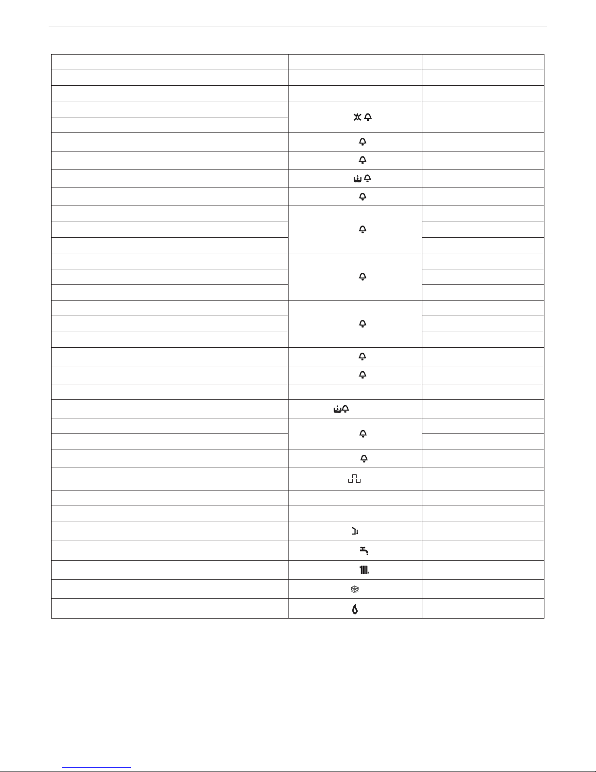
4.4 Faults
BOILER STATUS DISPLAY TYPES OF ALARMS
Off status(OFF) OFF None
Stand-by - Signal
ACF alarm lockout module
A01
Definitive lockout
ACF electronics fault alarm
Limit thermostat alarm
A02
Definitive lockout
Tacho fan alarm
A03
Definitive lockout
Water pressure switch alarm
A04
Definitive lockout
NTC domestic water fault
A06
Signal
NTC heating outlet fault
A07
Temporary stop
Heating outlet probe over-temperature Temporary then definitive
Outlet/return line probe differential alarm Definitive lockout
NTC heating return line fault
A08
Temporary stop
Heating return line probe over-temperature Temporary then definitive
Outlet/return line probe differential alarm Definitive lockout
Cleaning the primary heat exchanger
A09
Signal
NTC flue gases fault Temporary stop
Flue gases probe over-temperature Temporary then definitive
Parasite flame
A11
Temporary stop
Low temperature system thermostat alarm
A77
Temporary stop
Temporary pending ignition 80°C flashing Temporary stop
Water pressure switch intervention
flashing
Temporary stop
Calibration service
ADJ
Signal
Calibration installer
Chimney sweep
ACO
Signal
Vent cycle
Signal
Pre-heating enabled P Signal
Preheating heat request P flashing Signal
External probe presence
Signal
Domestic water heat request
60°C
Signal
Heating heat request
80°C
Signal
Antifreeze heat request
Signal
Flame present
Signal
Mynute Green E C.S.I.
11
To restore operation (reset alarms):
Faults A 01-02-03
Set the mode selector to
(OFF), wait 5-6 seconds and then return
it to the desired position (summer) or (winter). If the reset
attempts do not reactivate the boiler, request the intervention of the
Technical Assistance Centre.
Fault A 04
In addition to the fault code, the digital display displays the symbol
.
Check the pressure value indicated by the water gauge:
if it is less than 0.3 bar, position the function selector on OFF and
adjust the filling tap until the pressure reaches a value between 1
and 1.5 bar.
“Then position the mode selector to the desired position (summer) or (winter).
The boiler will carry out a venting cycle lasting about 2 minutes.
If pressure drops are frequent, request the intervention of the Technical Assistance Centre.
Fault A 06
The boiler functions normally but does not guarantee a constant domestic hot water temperature, which remains set at around 50°C.
Contact the Technical Assistance Centre.
Fault A 07
Contact the Technical Assistance Centre.
Fault A08
Contact the Technical Assistance Centre.
Fault A09
Set the mode selector to
(OFF), wait 5-6 seconds and then return
it to the desired position (summer) or (winter). If the reset attempts
do not reactivate the boiler, request the intervention of the Technical
Assistance Centre.
Fault A09
The boiler is equipped with an auto-diagnostic system which, based
on the total number of hours in certain operating conditions, can signal the need to clean the primary exchanger (alarm code 09 with flue
gases probe counter >2,500).
Once the cleaning operation has been completed, reset to zero the
total hour meter with special kit supplied as an accessory following
procedure indicated below:
disconnect the electrical supply;
remove the shell and turn the instrument panel;
remove the electrical parts inspection cover, undoing the 2 fixing
screws;
as you electrically power the boiler press the CO button for at least 4
seconds to check that the counter resets. Remove and restore power to the boiler; on the display the counter is shown after the “-C-”
indication.
Live electrical parts (230 Vac).
NOTE
The meter resetting procedure should be carried out after each indepth cleaning of the primary exchanger or if this latter is replaced.
To check the status of the totalled hours multiply the value shown by
100 (ex: shown value of 18 = pre totalled 1800 – shown value of 1=
totalled hours 100). The boiler continues to operate normally even
with the alarm active.
Fault A77
The fault is self-resetting, if the boiler does not restart contact the
Technical Assistance Centre.
4.5 Boiler configuration
On the electronic card there is a series of jumpers (JPX) which allow
the boiler to be configured; access is possible by removing the electrical parts inspection cover after setting the main switch to off.
To access the card operate as follows:
- set the system's main switch to off
- undo the shell fixing screws, then move the shell base forward and
then upwards to unhook it from the chassis
- lift and then turn the instrument panel upside down
- remove the electrical parts inspection cover, undoing the 2 fixing
screws to access the jumpers (fig. 38)
JUMPER JP7 - fig. 39:
pre-selection of the most appropriate boiler heating temperature adjustment field depending on the type of system.
Jumper not on - standard system
Standard system 40-80 °C.
Jumper on - floor system
Floor system 20-45 °C.
From the factory the boiler is configured for standard systems.
JP1 Enabling front knobs for calibration
JP2 Heating timer reset
JP3 Calibration (see “Adjustments” section)
JP4 Absolute domestic hot water thermostat selector
JP5 do not use
JP6
Enable night-time compensation function and pump in
continuous mode (only with external probe connected)
JP7
Enable standard/low temperature systems
management (see above)
JP8 Do not use
4.6 Setting the thermoregulation
Thermoregulation works only with the external probe connected,
therefore, once installed, connect the external probe to the specific
connection provided on the boiler terminal board.
This enables the THERMOREGULATION function.
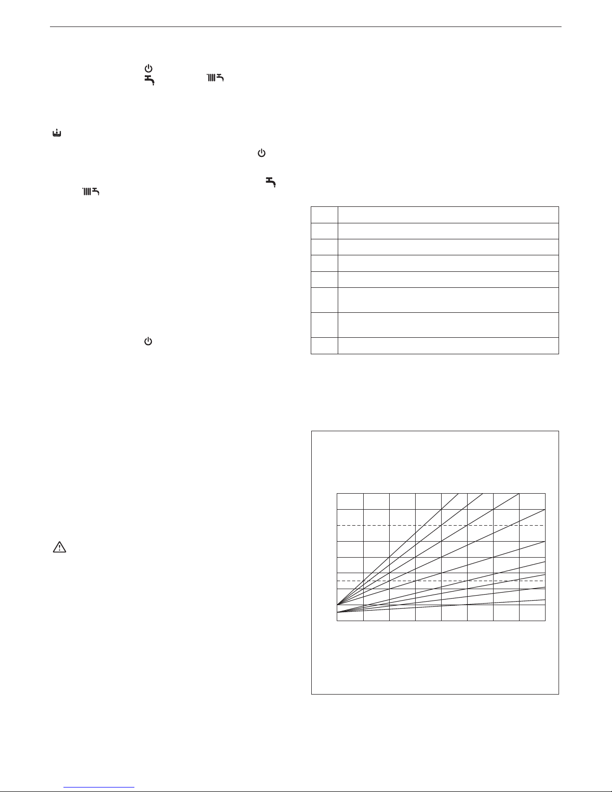
Choice of the compensation curve
CURVE DI TERMOREGOLAZIONE
Temperatura esterna (˚C)
Temperatura di mandata (˚C)
20
30
40
50
60
70
80
90
100
-20
0,2
0,4
0,6
0,8
1,0
1,5
2,02,53,0
T80
T45
-15-10-505101520
THERMOREGULATION CURVES
Outside temperature [°C]
Delivery temperature [°C]
T80 - maximum std system heating set point temperature
(JP7 not on)
T45 - maximum floor system heating set point temperature
(JP7 on)
the display shows the value of the KT curves multiplied by 10
(example 3.0 = 30)
The compensation curve for heating maintains a theoretical temperature of 20°C indoors, when the external temperature is between
+20°C and -20°C. The choice of the curve depends on the minimum
external temperature envisaged (and therefore on the geographical
location), and on the delivery temperature envisaged (and therefore
ENGLISH
12
on the type of system). It is carefully calculated by the installer on the
basis of the following formula:
KT =
Design delivery temp - Tshift
20 - Design min outside temp
Tshift = 30 °C standard system
25 °C floor system
If the calculation produces an intermediate value between two
curves, you are advised to choose the compensation curve nearest
the value obtained.
Example: if the value obtained from the calculation is 1.3, this is between curve 1.0 and curve 1.5. Choose the nearest curve, i.e. 1.5.
Selection of the KT must be made by acting on the P3 trimmer on the
card (see multi-wire electrical diagram).
To access P3:
1. remove the shell,
2. turn the instrument panel upside down
- remove the electrical parts inspection cover, undoing the 2 fixing
screws
Live electrical parts (230 Vac).
The following KT values can be set:
- standard system: 1.0 - 1.5 - 2.0 - 2.5 - 3.0
- floor system: 0.2 - 0.4 - 0.6 - 0.8
and they will be shown on the display for about 3 seconds after the
P3 trimmer is turned,
Location
Design minimum
outside temperature
Location
Design minimum
outside temperature
Location
Design minimum
outside temperature
Turin
Alexandria
Asti
Cuneo
Alta valle Cuneese
Novara
Vercelli
Aosta
Valle d’Aosta
Alta valle Aosta
Genoa
Imperia
La Spezia
Savona
Milan
Bergamo
Brescia
Como
Como Province
Cremona
Mantua
Pavia
Sondrio
Alta Valtellina
Varese
Trento
Bolzano
Venice
Belluno
Padua
Rovigo
Treviso
Verona
Verona lake area
Verona mountain area
-8
-8
-8
-10
-15
-5
-7
-10
-15
-20
0
0
0
0
-5
-5
-7
-5
-7
-5
-5
-5
-10
-15
-5
-12
-15
-5
-10
-5
-5
-5
-5
-3
-10
Vicenza
Vicenza highlands
Trieste
Gorizia
Pordenone
Udine
Lower Carnia
Upper Carnia
Tarvisio
Bologna
Ferrara
Forlì
Modena
Parma
Piacenza
Piacenza Province
Reggio Emilia
Ancona
Macerata
Pesaro
Florence
Arezzo
Grosseto
Livorno
Lucca
Massa
Carrara
Pisa
Siena
Perugia
Terni
Rome
Frosinone
Latina
Rieti
-5
-10
-5
-5
-5
-5
-7
-10
-15
-5
-5
-5
-5
-5
-5
-7
-5
-2
-2
-2
0
0
0
0
0
0
0
0
-2
-2
-2
0
0
2
-3
Viterbo
Naples
Avellino
Benevento
Caserta
Salerno
L’Aquila
Chieti
Pescara
Teramo
Campobasso
Bari
Brindisi
Foggia
Lecce
Taranto
Potenza
Matera
Reggio Calabria
Catanzaro
Cosenza
Palermo
Agrigento
Caltanissetta
Catania
Enna
Messina
Ragusa
Syracuse
Trapani
Cagliari
Nuoro
Sassari
-2
2
-2
-2
0
2
-5
0
2
-5
-4
0
0
0
0
0
-3
-2
3
-2
-3
5
3
0
5
-3
5
0
5
5
3
0
2
Based on experience, the installer can still choose different curves.
TYPE OF HEAT REQUEST
If an ambient thermostat is connected to the boiler (JUMPER 6
not on) (fig. 40)
The heat request is made by the closure of the room thermostat contact, while the opening of the contact produces a switch-off. The delivery temperature is automatically calculated by the boiler, although
the user may interact with the boiler. Using the interface to modify the
HEATING, you will not have the HEATING SET-POINT value available, but a value that you can set as preferred between 15 and 25°C.
The modification of this value will not directly modify the delivery temperature, but will automatically affect the calculation that determines
the value of that temperature, altering the reference temperature in
the system (0 = 20°C).
If an hourly timer is connected to the boiler (JUMPER JP6 not
on) (fig. JP6 41)
With the contact closed, the heat request is made by the delivery
probe, on the basis of the external temperature, to obtain a nominal
ambient temperature on DAY level (20°C). The opening of the contact does not produce a switch-off, but a reduction (parallel translation) of the climatic curve on NIGHT level (16°C).
This will activate the night time function.
The delivery temperature is automatically calculated by the boiler,
although the user may interact with the boiler.
Using the interface to modify the HEATING, you will not have the
HEATING SET-POINT value available, but a value that you can set
as preferred between 15 and 25°C.
The modification of this value will not directly modify the delivery temperature, but will automatically affect the calculation that determines
the value of that temperature, altering the reference temperature in
the system (0 = 20°C for DAY level, and 16°C for NIGHT level).

Mynute Green E C.S.I.
13
4.7 Adjustments
The boiler has already been adjusted by the manufacturer. However,
if adjustments must be repeated, for example after special maintenance, replacement of the gas valve or conversion from methane gas
to LPG or propane air, observe the following procedures.
The adjustment of the maximum and minimum output, the maximum
heating and slow ignition, must be made strictly in the sequence indicated, and by qualified personnel only:
1. disconnect the boiler power supply
2. turn the heating water temperature selector to its maximum, selector in correspondence to + (fig. 42)
3. lift and then turn the instrument panel upside down
4. remove the electrical parts inspection cover, undoing the 2 fixing
screws
5. insert jumpers JP1 and JP3 (fig. 43)
6. power the boiler.
“ADJ” will appear on the display for about 4 sec
Modify the following parameters:
7. absolute/domestic maximum
8. minimum
9. maximum heating
10. slow ignition
as described below:
11. turn the heating water temperature selector to set the desired
value
12. press the CO button (fig. 44) and move on to calibration of the
next parameter.
Live electrical parts (230 Vac).
The following icons will appear on the display:
1. during absolute/domestic maximum calibration
2. during minimum calibration
3. during heating maximum calibration
4. during slow ignition calibration
End the procedure removing jumpers JP1 and JP3 to store the set
values.
the function can be terminated at any time without storing the set
values and maintaining the previously set ones:
removing jumpers JP1 and JP3 before all 4 parameters have been
set
- turning the mode selector to OFF/RESET.
- disconnecting the mains voltage.
- 15 minutes after activation.
The calibration does not entail the ignition of the boiler.
By rotating the heating setpoint selector knob, the number of
rotations expressed in hundreds (e.g. 25 = 2500 rpm) is automatically displayed.
The calibration parameter display function is activated with the selector on summer or winter and pressing the CO button on the card
regardless of whether or not there is a heat request.
The function cannot be activated if a remote control is connected.
When this function is activated, the calibration parameters each appear (in the order shown below) for 2 seconds. The relative icon is
indicated in line with each parameter, and the fan rotation value (expressed in hundreds)
1. Maximum
2. Minimum
3. Maximum heating
4. Slow ignition
5. Adjusted maximum heating
GAS VALVE CALIBRATION
- Electrically power the boiler.
- Open the gas tap.
- Set the mode selector to OFF/RESET (display off).
- Remove the shell, turn the instrument panel upside down and re-
move the electrical parts inspection cover to access the “CO” button (fig. 45).
Press the “CO” button once.
Live electrical parts (230 Vac).
- Wait for the burner to ignite.
“ACO” appears on the display. The boiler operates at maximum
heating output.
The “combustion analysis” function remains active for a limited
time of 15 minutes; if a delivery temperature of 90°C is reached the
burner will extinguish. It will reignite when this temperature drops
below 78°C.
- insert the analyser probes in the prescribed positions on the air box
after removing the screws and the cover.
- Press the “combustion analysis” button a second time to reach the
number of revolutions that corresponds to the maximum domestic
hot water output (table 1).
- Check the CO
2
value: (table 4) if the value does not comply with
the indications in the table act on the gas valve max adjustment
screw (fig. 45).
- Press the “combustion analysis” button a third time to reach the
number of revolutions that corresponds to the minimum output (table 2).
- Check the CO2 value: (table 5) if the value does not comply with
the indications in the table act on the gas valve min adjustment
screw (fig. 45).
- To exit the “combustion analysis” function turn the command knob.
- Extract the gases analysis probe and refit the plug.
- Close the instrument panel and reassemble the shell.
The “combustion analysis” function automatically deactivates if the
card generates an alarm. In the event of a fault during the combustion analysis phase, carry out the reset procedure, acting on the
mode selector as described in section 4.4.
Table 1
Maximum
domestic hot
water fan
rotations
Methane
gas (G20)
Liquid gas
(G31)
25 C.S.I. 47 47 rpm
30 C.S.I. 56 56 rpm
Table 2
Minimum number
of fan rotations
Methane
gas (G20)
Liquid gas
(G31)
25 C.S.I. 14 14 rpm
30 C.S.I. 14 14 rpm
Table 3
Maximum number
of heating fan
rotations
Methane
gas (G20)
Liquid gas
(G31)
25 C.S.I. 39 39 rpm
30 C.S.I. 47 47 rpm
Table 4
Max CO
2
Methane
gas (G20)
Liquid gas
(G31)
25 C.S.I. 9.0 10.0 %
30 C.S.I. 9.0 10.0 %
Table 5
Min CO
2
Methane
gas (G20)
Liquid gas
(G31)
25 C.S.I. 9.0 10.0 %
30 C.S.I. 9.0 10.0 %
Table 6
Slow ignition
Methane
gas (G20)
Liquid gas
(G31)
25 C.S.I. 33 33 %
30 C.S.I. 33 33 %
4.8 Gas conversion
Conversion from a family gas to other family gas can be performed
easily also when the boiler is installed.
This operation must be carried out by professionally qualified personnel.

ENGLISH
14
The boiler is designed to operate with methane gas (G20) according
to the product label.
It is possible to convert the boiler to propane gas (G31) using the
special kit supplied.
For disassembly, refer to the instructions provided below (fig. 46):
- remove power supply from the boiler and close the gas tap
- remove in the following order: shell and air box cover
- unhook the instrument panel and turn it forward
- remove the gas train (A)
- remove the nozzle (B) - Fig.- contained in the gas train, and replace it with the one contained in the kit
- refit the gas train (ensure that the gas train connected to the fan
mixer is in position)
- refit the air box cover
- power-up the boiler and open the gas tap.
Adjust the boiler following the description in chapter 4.7 “Adjustments” referring to the data relative to the gas in question (G31).
Conversion must be carried out by qualified personnel.
After completing the gas conversion apply the new identifica-
tion label contained in the kit.
5 - REGULAR
To ensure product characteristics and efficiency remain intact and
to comply with prescriptions of current regulations, it is necessary to
render the appliance to systematic checks at regular intervals.
When carrying out maintenance work, observe the instructions given
in chapter 1 “Warnings and safety”.
Turn off the appliance before carrying out work or maintenance of
structures near the flue discharge connections and/or fume discharge devices and their accessories. Once work is completed, a
qualified technician must check the efficiency of the appliance.
IMPORTANT
Before carrying out any cleaning or maintenance work on the appliance, use appliance and system switches to interrupt power supply
and close the gas supply turning the tap placed on the boiler.
5.1 Routine maintenance
This normally means the following tasks:
- removing any oxidation from the burner;
- removing any scale from the heat exchangers;
- checking and cleaning the drainage pipes;
- checking the external appearance of the boiler;
- checking the ignition, switch-off and operation of the appliance, in
both domestic water mode and heating mode;
- checking the seal on the gas and water couplings and pipes;
- checking the gas consumption at maximum and minimum output;
- checking the position of the ignition-flame detection glowplug;
- check the “no gas” safety system;
- check operation of the check valve if it is installed (see section 3.10
“Installation on collective flues in positive pressure”).
Do not clean the appliance or its parts with easily inflammable substances (e.g. benzine, alcohol, etc.).
Do not clean panels, painted parts and plastic parts with paint thinner.
Panel cleaning must be carried out only with soapy water.
5.2 Extraordinary maintenance
These tasks restore appliance operation in accordance with the design and regulations - e.g. following the repair of an accidental fault.
This normally means:
- replacement
- repair
- overhaul of components.
These tasks require special means, equipment and tools.
During the initial installation phase, or in the event of extraor-
dinary maintenance, you are advised to activate the procedure
to discharge air from the heating circuit and boiler (see section
3.3).
5.3 Checking the combustion parameters
To carry out the combustion analysis, proceed as follows:
- Set the mode selector to to switch off the boiler (fig. 47)
- Turn the domestic hot water temperature selector to the position
(fig. 47)
- Wait for the burner to ignite (about 6 seconds). The display shows
“ACO” and the boiler operates at maximum heating output
- Remove the screw C and the cover E on the air box (see fig. 48)
- insert the analyser probes in the prescribed positions on the air box
The flue gas analysis probe should be inserted until its reaches
the stop.
- Check that the CO
2
values correspond to the ones indicated in the
tables shown below”; if the value shown is different proceed with
changes as indicated in the “Gas valve calibration” chapter.
Max CO
2
Methane
gas (G20)
Liquid gas
(G31)
25 C.S.I. 9.0 10.0 %
30 C.S.I. 9.0 10.0 %
Min CO
2
Methane
gas (G20)
Liquid gas
(G31)
25 C.S.I. 9.0 10.0 %
30 C.S.I. 9.0 10.0 %
- Perform the combustion check.
The “combustion analysis” function remains active for a limited
time of 15 minutes; if a delivery temperature of 90°C is reached the
burner will extinguish. It will reignite when this temperature drops
below 78°C.
- If you want to interrupt the procedure turn the domestic hot water
temperature selector so that it is within the + and - symbols.
Subsequently:
- remove the analyser probe and close the combustion analysis inlet
- close the instrument panel and refit the shell
When checks are completed:
- Position the knobs depending on the type of operation desired.
6 - CIRCULATOR SETTINGS
Circulator residual discharge head
The boilers is equipped with an already hydraulically and electrically
connected circulator, whose useful available performance is indicated in the graph.
The circulator comes set from the factory with a 6 metre discharge
head curve.
The boiler is equipped with an anti-blocking system which starts up
an operation cycle after every 24 hours in standby with the mode
selector in any position.
The "antiblocking" function is active only if the boiler is electri-
cally powered.
Operating the circulator without water is strictly forbidden.
If you need to use a different curve you can select the desired level
on the circulator.
Below the main characteristics and the ways to set up their desired
operation are listed.
User interface
The user interface is made up of a button (A), a two-coloured red /
green LED (B) and four yellow LEDs (C) arranged in a row (fig. 49).
The user interface allows the operating performance to be viewed
(operating status and alarm status) and it also allows the circulator
operating modes to be set.

Mynute Green E C.S.I.
15
The performance, indicated by the LEDs (B) and (C) is always visible
during normal operation of the circulator whereas the settings can be
carried out by pressing the button (A) (fig. 49).
Operating status indication
When the circulator is in operation the LED (B) is green (fig. 49). The
four yellow LEDs (C) indicate the electrical energy consumption (P1)
as shown in the following table
LED status CIRCULATOR status
Consumption in
% of MAX P1 (*)
Green LED on +
1 yellow LED on
Operating at minimum 0~25
Green LED on +
2 yellow LEDs on
Operating at
minimum-medium
25~50
Green LED on +
3 yellow LEDs on
Operating at medium-
maximum
50~75
Green LED on +
4 yellow LEDs on
Operating at maximum 100
(*) For the power (P1) absorbed by the circulator see the indications
in the “Technical Data” table.
Alarm status indication
If the circulator has detected one or more alarms the two-coloured
LED (B) will be red (fig. 49). The four yellow LEDs (C) indicate the
type of alarm as shown in the following table.
LED status
ALARM
description
Status
CIRCULATOR
Possible
SOLUTION
Red LED on +
1 yellow LED
on (LED 5)
The drive shaft
is jammed
Start attempt
every 1.5
seconds
Wait or unjam
the drive shaft
Red LED on +
1 yellow LED
on (LED 4)
Low input
voltage
Warning only.
The circulator
continues to
operate
Check the
input voltage
Red LED on +
1 yellow LED
on (LED 3)
Electrical power
supply fault or
faulty circulator
The circulator
is stopped
Check the
electrical
power supply
or replace the
circulator
If there are several alarms the circulator will display only the
alarm with the highest priority.
Display of active settings
With the circulator powered, press briefly on the button (A) to view
the active configuration of the circulator (fig. 49). The LEDs indicate
the active settings.
In this phase no variations can be made to the circulator configuration. Two seconds after the button (A) has been pressed the user
interface returns to the normal operating status display.
0 100 200 300 400 500 600 700 800 900 1000 1100 1200 1300
0
50
100
150
200
250
300
350
400
450
500
550
600
Modulation area
Discharge head [mbar]
6 METRES DISCHARGE HEAD
System capacity [l/h]
0 100 200 300 400 500 600 700 800 900 1000 1100 1200 1300 1400
0
100
50
150
200
250
300
350
400
450
500
550
600
650
Modulation area
Discharge head [mbar]
7 METRES DISCHARGE HEAD
System capacity [l/h]
0 100 200 300 400 500 600 700 800 900 1000 1100 1200
0
50
100
150
200
250
300
350
400
450
500
Modulation area
Discharge head [mbar]
5 METRES DISCHARGE HEAD
System capacity [l/h]
0 100 200 300 400 500 600 700 800 900 1000 1100
0
50
100
150
200
250
300
350
400
4 METRES DISCHARGE HEAD
Modulation area
System capacity [l/h]
Discharge head [mbar]

ENGLISH
16
Key lock function
The purpose of the key lock function is to prevent accidental modifications to the settings or the improper use of the circulator.
When the key lock function is activated, long-pressing the button (A)
is prevented. This prevents the user from entering the circulator's
operating modes setting section.
Enabling/disabling the key lock function is achieved by pressing the
button (A) (fig. 49) for more than 10 seconds. During this step all of
the LEDs (C) will flash for 1 second.
Changing the operating mode (fig. 50)
In normal operating conditions the circulator works with the factory
settings or the last settings carried out.
To change the configuration:
Ensure that the key lock function is deactivated.
Press the button (A) for more than 2 seconds until the LEDs begin
to flash. Short-press the button (A) within 10 seconds and the user
interface will move on to display the next settings. The various available settings will appear in a cyclic sequence.
If the button (A) is not pressed, the last setting will be stored (fig. 49).
If the button (A) is pressed you can move back to the “active settings
display” again and check that the LEDs (B) and (C) indicate (for 2
seconds) the last setting carried out.
If the button (A) is not pressed for more than 2 seconds the user
interfaces switches to the “Operating status display”.
The available settings are shown in fig. 51 along with the related
representation of LED (B) and (C).
IMPORTANT
If the 3 (5 metres) or 4 (4 metres) curves are set the bypass must
be replaced with the one supplied, following the procedure indicated
below (fig. 52):
Remove boiler electrical power by setting the system's main switch
to off.
Close the system taps and empty the boiler heating circuit.
Extract the bypass body cover fixing spring (D).
Extract the bypass body cover (E).
Replace the bypass valve (F) with the one included.
Refit the bypass body cover and its spring.

Mynute Green E C.S.I.
17
EN
USER
A - GENERAL WARNINGS
The instruction manual is an integral part of the product and it must
therefore be kept carefully and must accompany the appliance; if the
manual is lost or damaged, another copy must be requested from the
Technical Assistance Service.
The instruction manual is an integral part of the product and
it must therefore be kept carefully and must accompany the
appliance; if the manual is lost or damaged, another copy must
be requested from the Technical Assistance Service.
This boiler may only be installed and serviced by qualified per-
sonnel who comply with the national and local current regulations according to Ministerial Decree 37 of 2008 and in compliance with UNI-CIG 7129 and 7131 standards and as updated
and amended.
For the installation, you are advised to contact specialised per-
sonnel.
The boiler must only be used for the application foreseen by
the manufacturer. The manufacturer shall not be liable for any
damage to persons, animals or property due to errors in installation, calibration, maintenance or due to improper use.
The safety and automatic adjustment devices must not be
modified, during the system life cycle, by the manufacturer or
supplier.
This appliance produces hot water, therefore it must be con-
nected to a heating system and/or a domestic hot water mains,
compatible with its performance and output.
In case of water leakage, close the water supply and contact
the Technical Assistance Service immediately.
In case of absence for long periods time, close the gas supply
and switch off the electrical supply main switch. If there is a risk
of frost, drain the boiler.
From time to time check that the operating pressure of the hy-
draulic system does not decrease under 1 bar.
In case of failure and/or malfunctioning, deactivate the appli-
ance, and do not try to repair or intervene directly on it.
Appliance maintenance must be carried out at least once a
year: scheduling it with the Technical Assistance Service will
avoid wasting time and money.
Based on D.P.R. 16 April 2013 No. 74 the qualified engineer
pursuant to Ministerial Decree 22 January 2008 No. 37 (installing or servicing company), must establish the requirements
and frequency of the inspection operations and any system
service in order to guarantee the required safety. In the absence of these, the manufacturer's indications will prevail.
At the end of its life, the product should be not be disposed of
as solid urban waste, but rather it should be handed over to a
differentiated waste collection centre.
B - FOR YOUR SAFETY
Boiler use requires to strictly observe some basic safety rules:
Do not use the appliance in any manner other than its intended
purpose.
It is dangerous to touch the appliance with wet or damp body
parts and/or in bare feet.
Under no circumstances cover the intake grids, dissipation
grids and ventilation vents in the installation room with cloths,
paper or any other material.
Do not activate electrical switches, telephone or any other ob-
ject that causes sparks if there is a smell of gas. Ventilate the
room by opening doors and windows and close the gas central
tap.
Do not place anything in the boiler.
Do not perform any cleaning operation if the appliance is not
disconnected from the main power supply.
Do not cover or reduce ventilation opening of the room where
the generator is installed.
Do not leave containers and inflammable products in the instal-
lation room.
Do not attempt to repair the appliance in case of failure and/or
malfunctioning.
It is dangerous to pull or twist the electric cables.
it is forbidden to intervene on sealed elements.
Children or unskilled persons must not use the appliance.
It is forbidden to obstruct the condensate outlet.
For better use, remember that:
- a periodic external cleaning with soapy water not only improves its aesthetic aspect but also preserves panelling from
corrosion, extending its life cycle;
- if the wall-mounted boiler is enclosed in pendant furniture,
leave at least 5 cm for ventilation and maintenance;
- installation of an ambient thermostat will favour a greater
comfort, a more rational use of the heat and energy saving;
the boiler can also be connected to a programming clock in
order to manage ignition and switching off during the day or
week.
C - IGNITION
Activation of the boiler's Statutory Warranty must be carried out by
the Technical Assistance Service.
At the same time, if it is necessary to put the appliance in service
again, carefully follow the described operations.
Each time the boiler is electrically powered, it begins an automatic
venting cycle that lasts about 2 minutes. During this phase the
symbol will appear on the display (fig. 25).
To start-up the boiler it is necessary to carry out the following operations:
- electrically power the boiler;
- open the gas tap present in the system to allow fuel flow;
- adjust the ambient thermostat to the required temperature (~20°C);
- turn the mode selector to the desired position.
Winter
Turning the mode selector within the area marked with + and - (fig.
27) the boiler provides domestic hot water and heating.
The boiler lights automatically in response to a heat request.
The digital monitor (5) indicates the heating water temperature (fig.
28).
The boiler ignites automatically in response to a request for domestic
hot water and the display (5) indicates the domestic hot water temperature (fig. 29).
Adjusting the heating water temperature
To adjust the heating water temperature, turn the knob with the
“
” symbol (fig. 27) so that it is within the area marked with
+ and -.

ENGLISH
18
Adjusting the heating water temperature with an external probe
connected
When an external probe is installed, the delivery temperature is automatically selected by the system, which quickly adjusts the ambient temperature according to variations in the outside temperature.
If you want to alter the temperature value (increasing or reducing
the value automatically calculated by the electronic card), use the
heating water temperature selector: turn it clockwise to increase the
temperature, or anticlockwise to reduce it. The correction possibility
is between -5 and +5 levels of comfort, shown on the digital display
by rotating the knob.
Summer
Turning the mode selector to the summer symbol
(fig. 30) the
traditional function of only domestic hot water is activated. The boiler
ignites automatically in response to a request for domestic hot water
and the digital monitor (5) indicates the domestic hot water temperature (fig. 4.3b).
Pre-heating (faster hot water)
Positioning the mode selector to summer or winter and turning the
domestic hot water temperature adjustment knob to the
symbol
(Fig. 31) the pre-heating function is activated. Bring the domestic hot
water temperature adjustment knob back to the required position.
This function keeps the water in the domestic hot water exchanger hot, to reduce standby times when a request is made. When the
pre-heating function is enabled, the
symbol is on (fig. 31).
The display indicates the outlet temperature of the heating water or
the domestic hot water based upon the request in progress.
During burner ignition following a pre-heating request, the monitor
indicates the symbol.
To deactivate the pre-heating function, rotate the domestic hot water
temperature adjustment knob back to the symbol .
Bring the domestic hot water temperature adjustment knob back to
the required position.
This function cannot be activated when the boiler is OFF: mode selector set to (OFF) (fig. 32).
Adjustment of the domestic hot water temperature
To adjust domestic water temperature (bathrooms, showers, kitchen, etc.), turn the knob with the
symbol (fig. 33) within the area
marked with + and -.
The boiler is in standby until the burner switches on following a heat
request.
The boiler continues to function until the temperatures set on the
boiler are reached, or the heat request terminates; it will then go back
to standby.
If the red indicator light near the symbol (Fig. 34) on the command panel lights up, this means the boiler is in temporary stop status (see the chapter on light signals and faults).
The digital monitor indicates the fault code detected (fig. 34).
Automatic Ambient Adjustment System (S.A.R.A.) (fig. 35)
By setting the heating water temperature selector to the area marked
by AUTO, the S.A.R.A. self-adjusting system is activated (frequency
0.1 sec. on; - 0.1 sec. off; duration 0.5): according to the temperature
set on the ambient thermostat and the time employed to reach it,
the boiler varies automatically the heating water temperature reducing the operating time, allowing great operation comfort and energy
saving.
Reset function
To restore operation, set the mode selector to
off (fig. 36), wait
5-6 seconds then bring it to the required position, checking that the
red indicator light is off.
At this point the boiler will automatically start and the red lamp switches on in green.
N.B. If the attempts to reset the appliance do not activate operation,
contact the Technical Assistance Centre.
D - SWITCHING OFF
Temporary switch-off
In the event of absence for short periods of time, set the mode selector (fig. 36) to (OFF).
In this way (leaving the electricity and fuel supplies enabled), the
boiler is protected by the following systems:
Antifreeze: when the temperature of the water in the boiler drops
below 5°C the circulator starts and, if necessary, the burner at minimum output to bring the water temperature to safety values (35°C).
During the anti-frost cycle, the symbol (fig. 37) appears on the
digital monitor.
Circulator antiblocking: an operation cycle is activated every 24 h.
Switching off for lengthy periods
In the event of absence for short periods of time, set the mode selector (fig. 36) to
(OFF).
Turn the main system switch OFF.
Turn off the fuel and water taps of the heating and domestic hot water
system. In this case, anti-frost device is deactivated: empty the systems, in case of risk of frost.
E - LIGHT SIGNALS AND FAULTS
BOILER STATUS DISPLAY TYPES OF ALARMS
Off status (OFF) OFF None
Stand-by - Signal
ACF alarm lockout module
A01
Definitive lockout
ACF electronics fault alarm
Limit thermostat alarm
A02
Definitive lockout
Tacho fan alarm
A03
Definitive lockout
Water pressure switch alarm
A04
Definitive lockout
NTC domestic water fault
A06
Signal
 Loading...