

Beretta MYNUTE GREEN 50 R.S.I. Installation And User Manual

MYNUTE GREEN 50 R.S.I.
Installation and User Manual
EN
Manuel d'Utilisation et d'Installation
Manual de Instalación y Uso
Manual Usuário e Instalação
FR
ES
PT
Installation and User Manual

2
RANGE RATED
This boiler can be adapted to the thermal requirements of the system; it is possible, in fact, to set the maximum boiler delivery for operation in heat
mode. Refer to the “Adjustments” chapter for the calibration settings.
Once the desired output has been set (maximum heating) transfer the value into the table given on the back cover.
For subsequent checks and adjustments, always refer to the set value.
Mynute Green 50 R.S.I. boilers comply with the essential requirements of the following Directives:
- Gas Appliance Directive 2009/142/EC
- Efficiency directive: Article 7(2) and Annex III of directive 92/42/EEC
- Electromagnetic Compatibility Directive 2014/30/EU
- Low Voltage Directive 2014/35/EU
- Regulation 677 for condensation boilers
EN
RANGE RATED
Esta caldera puede ser adaptada a los requisitos térmicos del sistema; de hecho, es posible congurar el caudal de la caldera a máximo para la
operación en modo caliente. Consultar el capítulo “Regulaciones” para la regulación.
Una vez que se establece la potencia deseada (calentamiento máximo), transera el valor a la tabla dada en la cubierta trasera.
Para los controles y regulaciones posteriores tomar como referencia el valor congurado.
Las calderas Mynute Green 50 R.S.I. cumplen con los requisitos
esenciales de las siguientes Directivas:
- Directiva Gas 2009/142/CE
- Directiva Rendimiento: Artículo 7(2) y en el anexo III de la Directiva 92/42/CEE
- Directiva Compatibilidad Electromagnética 2014/30/UE
- Directiva Baja Tensión 2014/35/UE
- Norma 677 para calderas de condensación
ES
RANGE RATED
Cette chaudière peut être adaptée aux exigences thermiques du système. En effet, il est possible de régler la puissance maximale de la chaudière
pour le fonctionnement en mode Chauffage. Se référer au chapitre “Réglages” pour consulter les paramètres de réglage.
Une fois que la puissance a été réglée (paramètre de chauffage maximum), transférer la valeur dans le tableau présent sur le couvercle arrière.
Pour les contrôles et les réglages ultérieurs, se référer à cette valeur.
Les chaudières Mynute Green 50 R.S.I. sont conformes aux exigences essentielles des directives suivantes:
- Directive Gaz 2009/142/CE
- Directive sur le rendement: Article 7(2) et Annexe III de la directive 92/42/CEE
- Directive Compatibilité Électromagnétique 2014/30/UE
- Directive Basse Tension 2014/30/UE
- Règlement 677 pour chaudières à condensation
FR
PT
As caldeiras Mynute Green 50 R.S.I. estão em conformidade
com as especicações essenciais das seguintes Directivas:
- Directiva de gás 2009/142/CE
- Diretiva de rendimento: Artigo 7(2) e no Anexo III da diretiva
92/42/CEE
- Directiva de Compatibilidade Electromagnética 2014/30/UE
- Directiva Baixa tensão 2014/35/UE
- Regulação 677 para caldeiras de condensação
RANGE RATED
Esta caldeira pode ser adaptada às especicações térmicas do sistema; é possível de facto, estabelecer o caudal máximo da caldeira para
funcionamento em modo de aquecimento. Consultar o capítulo “Regulações” para a calibragem.
Uma vez que a potência desejada tenha sido programada (aquecimento máximo), transra o valor para a tabela dada na capa traseira.
Para controlos e regulações subsequentes, consultar portanto o valor congurado.
Installation manual ......................................................................3
User guide .................................................................................12
Control panel .............................................................................55
Electric diagrams ......................................................................57
Boiler operating elements .........................................................67
Hydraulic circuit ........................................................................68
EN
Manuel d’installation .................................................................16
Manuel d’utilisation ....................................................................25
Tableau de contrôle ...................................................................55
Schémas électriques .................................................................57
Éléments fonctionnels de la chaudière ......................................67
Circuit hydraulique .....................................................................68
FR
ES
Manual del instalador ...............................................................29
Manual de usuario .....................................................................38
Cuadro de control ......................................................................55
Esquema eléctrico .....................................................................57
Elementos de operación de la caldera ......................................67
Circuito hidráulico ......................................................................68
PT
Manual do instalador .................................................................42
Manual do usuário .....................................................................51
Painel de controlo ......................................................................55
Diagramas eléctricos .................................................................57
Elementos de operação da caldeira ..........................................67
Circuito hidráulico ......................................................................68
0476
0476CQ1376

3
1 - WARNINGS AND SAFETY
INSTALLATION MANUAL
EN
The boilers produced in our plants are built with great attention to
detail and every component is checked in order to protect users
and installers from injury. After working on the product, qualied
personnel must check the electrical wiring, in particular the stripped
part of conductors, which must not stick out from the terminal board,
avoiding possible contact with live parts of said conductor.
This instruction manual are integral parts of the product: make sure
it remains with the appliance, even if it is transferred to another
owner or user, or moved to another heating system. In case of loss
or damage, please contact your local Technical Assistance Service
for a new copy.
Boiler installation and any other assistance and maintenance opera-
tions must be carried out by qualied personnel according to the
provisions of the legislation in force.
The installer must instruct the user about the operation of the appli-
ance and about essential safety regulations.
To use the boiler’s automatic anti-freeze protection function (for tem-
peratures down to -1°C), based on burner operation, the appliance
must be able to switch on. This means that any lockout condition
(e.g. lack of gas/electricity supply, or safety device intervention) will
deactivate the protection.
This boiler must only be used for the application it was designed
for. The manufacturer declines all contractual and non-contractual
liability for injury to persons or animals or damage to property deriving
from errors made during installation, adjustment and maintenance
and from improper use.
After removing the packaging, make sure the contents are in good
condition and complete. Otherwise, contact the dealer from whom
you purchased the appliance.
The safety valve outlet must be connected to a suitable collection
and venting system. The manufacturer declines all liability for any
damage caused due to any operation carried out on the safety valve.
Dispose of all the packaging materials in the suitable containers at
the corresponding collection centres.
Dispose of waste by being careful not to harm human health and
without employing procedures or methods which may damage the
environment.
During installation, inform the user to:
- in the event of water leaks, the water supply must be shut off and
the Technical Assistance Service must be contacted immediately.
- it is necessary to periodically check that the operating pressure of
the hydraulic system is above 1 bar. If necessary, reset the pressure as indicated in the paragraph entitled “Filling the system”
- if the boiler is not used for a long time, the following operations
are recommended:
- turn the main switch of the appliance and the main switch of the
system to the “off” position
- close the fuel and water taps of the heating system
- drain the heating system to prevent freezing.
For safety, always remember that:
the boiler should not be used by children or unassisted disabled
people
it is dangerous to activate electrical devices or appliances (such as
switches, home appliances, etc.) if you smell gas or fumes. In the
event of gas leaks, ventilate the room opening doors and windows;
close the main gas tap; contact the Technical Assistance Service or
professionally qualied personnel immediately
do not touch the boiler while barefoot, or if parts of your body are
wet or damp
before any cleaning operations, disconnect the boiler from the mains
power supply by turning the two-position system switch and the main
control panel switch to the “OFF” position
do not modify safety and adjustment devices without the manufac-
turer's permission and relative instructions
In some parts of the manual, some symbols are used:
WARNING = for actions requiring special care and adequate preparation
FORBIDDEN = for actions that MUST NOT be performed
do not pull, disconnect or twist the electric cables coming out of the
boiler, even when it is disconnected from the mains power supply
avoid covering or reducing the size of the ventilation openings in
the installation room
do not leave inammable containers and substances in the instal-
lation room
keep packaging materials out of the reach of children
it is forbidden to obstruct the condensate drainage point.
2 - DESCRIPTION
MYNUTE GREEN 50 R.S.I. is a Type C wall-mounted condensing boiler
capable of operating under different conditions through a series of jumpers
on the electronic board (as described in “Boiler conguration”):
CASE A
heating only without any external storage tank connected.
The boiler does not supply domestic hot water.
CASE B
heating only with a thermostatically controlled external storage tank connected: in this condition, with every heat request from the storage tank
thermostat, the boiler supplies hot water for the preparation of the domestic
hot water.
CASE C
heating only, with the connection of an external storage tank (accessory kit
available upon request) (managed by a temperature probe) for preparing
domestic hot water. When connecting the storage tank not supplied by us,
make sure that the NTC probe has the following characteristics: 10 kOhm
at 25°C, B 3435 ±1%.
According to the ue gas used, the boiler is classied in the following categories B23P;B53P; C13,C13x; C23; C33,C33x; C43,C43x; C53,C53x;
C63,C63x; C83,C83x; C93,C93x.
In conguration B23P/B53P (when installed indoors), the appliance cannot
be installed in bedrooms, bathrooms, showers or where there are open
replaces without a proper air ow. The room where the boiler is installed
must have proper ventilation.
In conguration C, the appliance can be installed in any type of room and
there are no limitations due to ventilation conditions or room volume.
The main technical characteristics of the appliance are:
- pre-mix, low emissions burner
- microprocessor card to control inputs, outputs and alarm management
- continuous electronic ame modulation in heat mode
- electronic ignition with ame ionisation control
- continuous current fan controlled by Hall-effect revolutions counter
- built-in gas pressure stabiliser
- NTC probe to control delivery temperature of the primary circuit
- NTC probe to control return temperature of the primary circuit
- device for separation and automatic purging of air
- 3-way valve with electric actuator (as accessory)
- water pressure switch
- hydrometer to visualise heating water pressure
- circulator anti-blocking device
- airtight combustion chamber
- electrically operated gas valve with dual shutter to command the burner
- external probe for thermoregulation (as accessory)
- self-diagnostics for signalling the cleaning of the primary circuit heat
exchanger
- circulator
- Range Rated - this means the boiler is equipped with a device that
adapts it to the heat requirements of the system, so the boiler output
can be adjusted according to the energy needs of the building.
The safety devices of the appliance are:
- a water limit thermostat, to check for any overheating of the appliance
and thereby ensure the 100% safety of the system. To restore operation
if the limit thermostat is triggered, press the button on the right, beneath
the boiler shelf
- a ue gas probe - this intervenes (putting the boiler in safety stop mode)
if the temperature of the combustion products exceeds the maximum
operating temperature of the discharge pipes
- a safety valve at 3.5 bar
- a microprocessor check of probe continuity, with any faults indicated on
the display
- a drain-tap with oat, for discharging the condensate and preventing the
leakage of ue gases
- a condensate level sensor - this intervenes by blocking the boiler if the
level of condensate in the heat exchanger exceeds the limit allowed
- a rst level anti-freeze function (for installation area temperatures down
to -1°C), using the NTC heating probe
4
- a second level anti-freeze function (for installation area temperatures down
to -15°C), using the electric resistor kit that prevents the condensate in
the boiler from freezing
- diagnosis for absence of circulation (via the display of the temperatures
read by the delivery and return probes)
- a differential pressure switch allowing burner ignition if a minimum water
circulation is guaranteed in the primary circuit heat exchanger
- diagnosis for absence of water (via the pressure sensor)
- a ue gas safety evacuation system incorporated in the pneumatic
operation of the gas valve
- diagnosis for overtemperature (on both the delivery and return lines, with
dual probe - limit temperature 95°C
- a fan check, via a Hall-effect revolutions counter: the rotation speed of
the fan is always monitored.
The boiler is suitable for the connection of the following devices:
- an external 3-way valve
- a supplementary circulator
- an ambient thermostat or hourly timer
- an external probe for thermoregulation
- a remote control
- a safety thermostat for low temperature systems
- a remote thermostat or storage tank probe.
3 - INSTALLATION
3.1 Installation regulations
Installation must be carried out by qualied personnel, in accordance with
local regulations.
POSITION
The boiler can operate in a temperature range from -15°C to +60°C.
ANTI-FREEZE SYSTEM
The boiler is tted as standard with an automatic anti-freeze system that activates when the temperature of the water in the primary circuit falls below 6°C.
This system is always active, guaranteeing boiler protection down to an
installation area temperature of -1°C.
To take advantage of this protection (based on burner operation), the
boiler must be able to switch itself on; any lockout condition (for ex.
due to a lack of gas or electrical supply, or the intervention of a safety
device) therefore deactivates the protection.
Should it be necessary to protect the boiler for installation area tem-
peratures down to -15°C, you must use the specic anti-freeze kit that
prevents the condensate in the boiler from freezing.
To use the anti-freeze protection, an electrical\ supply is required; this
means that any blackout or disconnection will deactivate the protection.
The anti-freeze protection is also active when the boiler is on standby.
In normal operation conditions, the boiler can protect itself against freezing.
In areas where temperatures may fall below 0°C, or when the machine is left
unpowered for long periods, you are advised to use a good quality anti-freeze
liquid in the primary circuit to avoid the risk of freezing if you do not want to
drain the heating system. Carefully follow the manufacturer’s instructions
with regards not only the percentage of anti-freeze liquid to be used for the
minimum temperature at which you want to keep the machine circuit, but
also the duration and disposal of the liquid itself. For the hot domestic water
part, we recommend you drain the circuit.
The boiler component materials are resistant to ethylene glycol based antifreeze liquids.
MINIMUM DISTANCES
In order to have access to the boiler to perform regular maintenance opera-
tions, respect the minimum clearances foreseen for installation (g. 16a).
For correct appliance positioning:
- do not place it on a cooker or other cooking device
- do not leave inammable products in the room where the boiler is installed
- heat sensitive walls (for example, wooden walls) must be protected with
proper insulation.
IMPORTANT
Before installation, wash all system piping carefully in order to remove any
residues that may impair the operation of the appliance.
Connect the drain manifold to a suitable drainage system (for details, refer to chapter 3.6). The domestic hot water circuit does not need a safety
valve, but make sure that the pressure of waterworks does not exceed 6
bar. In case of doubts, install a pressure reducer. Prior to ignition, make
sure that the boiler is designed to operate with the gas available; this can
be checked by the message on the packaging and the adhesive label indicating the gas type. It is very important to highlight that in some cases the
smoke pipes are under pressure and therefore, the connections of several
elements must be airtight.
3.2 Cleaning the system and characteristics of the
heating circuit water
In the case of a new installation or replacement of the boiler, it is necessary
to clean the heating system. It is advisable to place a lter on the system to
hold back the impurities (a sludge remover lter).
To ensure the device works well, top up the additives and/or chemical treatments (e.g. antifreeze liquids, lming agents, etc.) and check the parameters in the table are within the values indicated.
Parameters Unit of
measurement
Hot water
circuit
Filling
water
pH value 7–8 -
Hardness °F - 15–20
Appearance
- clear
3.3 Securing the boiler to the wall and hydraulic
connections
Before installing, check you have the necessary spaces for the system,
considering the dimensions of the boiler, the ue gas discharge system,
and the hydraulic circuit.
The boiler is supplied as standard with a boiler support plate F (g.16). The
position and dimensions of the hydraulic connections are shown in detail.
In addition, a cardboard template is included with the standard equipment
to assist the installer in his work.
For the assembly, proceed as follows:
- x the boiler support plate to the wall and, with the aid of a level, check it
is perfectly horizontal
- mark the position of the 4 holes needed for xing the boiler support plate
- check all the measurements are precise, then drill the holes using a bit
with the diameter indicated above
- x the plate to the wall
For mounting accessories, refer to the instructions supplied.
Make the hydraulic connections and provide the discharge of the safety
valve and the 3-way tap (if installed).
The manufacturer is not liable for damage caused by the failure to
connect the discharges of the devices in question.
Make the hydraulic connections.
3.4 Installing the upper cover
Fit the upper cover and x it to the boiler with the screws A (g. 17) supplied.
The cover must be tted before installing the suction and ue gas
discharge system.
When you need to remove the casing, loosen the 3 xing screws of
the upper cover.
The manufacturer will not be liable for any damage resulting from the
failure to t the covers.
3.5 Installationoftheexternalsensor(g.19)
The correct operation of the external sensor is fundamental for the good
operation of the climate control.
INSTALLING AND CONNECTING THE EXTERNAL SENSOR
The sensor must be installed on an external wall of the building to be heated, observing the following indications:
it must be mounted on the side of the building most often exposed to winds
(the NORTH or NORTHWEST facing wall), avoiding direct sunlight; it must
be mounted about two thirds of the way up the wall;
it must not be mounted near doors, windows or air outlet points, and must
be kept away from smoke pipes or other heat sources.
The electrical wiring to the external sensor is made with a bipolar cable
with a section from 0.5 to 1 mm2 (not supplied), with a maximum length
of 30 metres. It is not necessary to respect the polarity of the cable when
connecting it to the external sensor. Avoid making any joints on this cable
however; if joints are absolutely necessary, they must be watertight and
well protected. Any ducting of the connection cable must be separated from
live cables (230V AC).
FIXING THE EXTERNAL SENSOR TO THE WALL
The sensor must be xed on a smooth part of the wall; in the case of exposed brickwork or an uneven wall, look for the smoothest possible area.
Loosen the plastic upper protective cover by turning it anticlockwise.
After deciding on the best xing area of the wall, drill the holes for the 5x25
wall plug.
Insert the plug in the hole. Remove the board from its seat.
Fix the box to the wall, using the screw supplied.
Attach the bracket, then tighten the screw.
Loosen the nut of the cable grommet, then insert the sensor connection
cable and connect it to the electric clamp.
To make the electrical connection between the external sensor and the
boiler, refer to the “Electrical wiring” chapter.
Remember to close the cable grommet properly, to prevent any
humidity in the air getting in through the opening.
Put the board back in its seat.
Close the plastic upper protective cover by turning it clockwise. Tighten the
cable grommet securely.

5
3.6 Condensate collection
The system must be set up so as to avoid any freezing of the condensate
produced by the boiler (e.g. by insulating it). You are advised to install a
special drainage collection basin in polypropylene (widely available on
the market) on the lower part of the boiler (hole Ø 42), as shown in g.18.
Position the exible condensate drainage hose supplied with the boiler,
connecting it to the manifold (or another connection device which allows inspection) avoiding creating any bends where the condensate could collect
and possibly freeze. The manufacturer will not be liable for any damage
resulting from the failure to channel the condensate, or from its freezing.
The drainage connection line must be perfectly sealed, and well protected
from the risk of freezing. Before the initial start-up of the appliance, check
the condensate will be properly drained off.
3.7 Gas connection
The gas connection must be made respecting the installation regulations in
force, and sized to ensure the correct gas delivery to the burner.
Before making the connection, check that:
- the gas type is suitable for the appliance
- the piping is thoroughly clean
It is advisable to install a lter of suitable dimensions on the gas line if the
distribution network contains solid particles.
Once the appliance has been installed, check the connections are sealed
according to current installation regulations.
3.8 Electrical wiring
To access the electrical wiring, proceed as follows.
To access the terminal board:
- turn off the main switch on the system
- undo the xing screws (D) on the housing (g. 20)
- move the base of the housing forwards and then upwards to unhook it
from the chassis
- undo the xing screws (E) from the instrument panel (g. 20)
- lift then turn the instrument panel towards you
- loosen the screw that xes the electric connections box, then remove the
box from its seat.
One side of the box contains the high voltage electric connections
(230V), while the other side contains the low voltage ones (g. 23-24).
Refer to the wiring diagrams when making the connections. The connection
to the mains supply must be made via a separation device with an omnipolar
opening of at least 3.5mm (EN 60335-1, category III). The appliance operates
with an alternating current of 230 Volt/50 Hz and complies with the standard
EN 60335-1. It is obligatory to make the connection with a safe earthing, in
compliance with the current directives.
It is also advisable to respect the phase-neutral connection (L-N).
The earth wire must be a couple of cm longer than the others.
The boiler can operate with a phase-neutral or phase-phase supply. For
power supplies that are not earthed, it is necessary to use an isolating
transformer with earth-anchored secondary.
Do not use gas and/or water pipes to earth electrical
appliance.
Low voltage room thermostat input (24V DC).
The installer is responsible for ensuring the appliance is suitably
earthed; the manufacturer will not be liable for any damage resulting
from an incorrect or absent earth connection.
Use the power cable supplied to connect the boiler to the mains power
supply. If the power cable needs to be replaced, use a cable of the HAR
H05V2V2-F type, 3 x 0.75mm2, with a maximum external diameter of
7mm.
SAFETY
THERMOSTAT
SAFETY
PRESSURE SWITCH
BOILER
WARNINGS
- For the electrical wiring of the pressure switch and the I.S.P.E.S.L. safety
thermostat (if installed), refer to the enclosed diagram.
3.9 Fillingtheheatingsystem
Once the hydraulic connections have been carried out, ll the heating system.
This operation must be carried out with cold system following this instructions:
- open the plug of the boiler’s automatic air vent (A) - g. 31 by turning it
two or three times; to allow a continuous air discharge, leave the plug
open
- open the radiator drain valves
- turn on the lling tap (outside the boiler) and wait until the pressure indicated
on the hydrometer is between 1.5 bar and 2 bar. The lling procedure
must be carried out slowly, in order to free the air bubbles in the water
and allow them to be released via the boiler and heating system vents.
For the instructions on how to free the air bubbles, refer to the specic
paragraph
- close the lling tap
- close the radiator drain valves when only water begins to seep out of them.
WARNING: the boiler is not tted with an expansion tank, so you must install
a closed tank on the system to ensure the appliance functions correctly.
The dimensions of the expansion tank must be suitable for the heating
system characteristics, and the tank capacity must meet the requisites of
the current regulations.
If the pressure value approaches 3.5 bar, there is the risk of the safety valve
being triggered. In this case, you should request the intervention of profes-
sionally qualied personnel.
Emptying the heating system
Before starting emptying, switch off the electricity supply by turning off the
main switch of the system.
- Turn off the heating system taps.
- Manually loosen the system drain valve (B) - g. 32 - and connect the pipe
(supplied with the boiler) to it in order to drain the water into an external
container.
3.10 Bleeding the air from the heating circuit and boiler
During the initial installation phase, or in the event of extraordinary maintenance, you are advised to perform the following sequence of operations:
1. Use a CH11 spanner to open the manual air vent valve located above
the air distribution box (g.15). Connect the tube (supplied with the boiler) to the valve, so the water can be drained into an external container.
2. Open the system lling tap located on the hydraulic unit and wait until
water begins to drain out of the valve.
3. Switch on the electricity supply to the boiler, leaving the gas tap turned
off.
4. Activate a heat request via the room thermostat or the remote control
panel, so that the 3-way valve goes into heating mode.
5. Activate a DHW request as follows:
heating-only boilers connected to an external storage tank: activate
the thermostat on the storage tank.
6. Carry on with the sequence until only water leaks out of the manual
air vent valve, and the air ow has stopped. Close the manual air vent
valve.
7. Check the system pressure level is correct (the ideal level is 1 bar).
8. Turn off the system lling tap.
9. Turn on the gas tap and ignite the boiler.
3.11 Circulator
Boilers are equipped with a circulator (already hydraulically and electrically
connected) whose effective performance levels are shown in the chart.
The boilers are equipped with an anti-blocking system which starts up
an operation cycle after every 24 hours of stop, with the mode selector
in any position.
The “anti-blocking” function is active only if the boilers are electrically
powered.
It is strictly forbidden to operate the circulator without water.
Maximum allowed water output <2200 l/h
A minimum output of 800 l/h must be guaranteed in the boiler, to
prevent the differential pressure switch being triggered.
To connect the system, we recommend the aid of a hydraulic separator
(supplied as an accessory), connected as shown in the diagrams
(g. 8-9).

6
3.12 Flue gas discharge and air suction
Observe local legislation regarding ue gas discharge.
The discharge of ue gas is guaranteed by the centrifugal fan tted in the
boiler. The boiler is supplied without the ue gas outlet/air suction kit, since it
is possible to use the accessories for appliance with a forced draught sealed
chamber that better adapts to the installation characteristics.
For ue gas discharge and the restoration of boiler combustion air, it is
essential to use only our original, specic pipes for condensation boilers,
and to ensure that the connection is made correctly (as indicated in the
instructions supplied with the ue gas accessories).
The boiler is a C-type applian ce (with airtight chamber), and must therefore
have a safe connection to the ue gas discharge pipe and to the combustion
air suction pipe; these both carry their contents outside, and are essential
for the operation of the appliance.
Both concentric and twin terminals are available.
The maximum lengths of the ducts refer to ue systems available in
the catalogue.
The boiler is designed to take in and dispose of ue gas condensate
and/or meteoric water condensate deriving from the ue gas discharge
system. It does this via its own drain-tap, if an external drain-tap is
not tted during the design or installation phase.
WARNING: if a condensate relaunch pump is installed, check the
technical data (provided by the manufacturer) regarding output, to
ensure it operates correctly.
“FORCEDOPEN”INSTALLATION(TYPEB23P-B53P)-g.25
Flue gas discharge pipe ø 80mm
To arrange this conguration, you must use the specic connection point
supplied as an accessory.
For installation, follow the instructions supplied with the kit.
In this case, the combustion air is picked up from the boiler installation
room (which must be a suitable technical room with proper ventilation).
The non insulated ue gas outlet pipes are potential sources of danger.
Arrange the ue gas discharge pipe so it slopes by 3° towards the
boiler.
maximum length of the ue gas discharge
pipe ø 80mm
pressure drop
45° curve 90° curve
30 m 1 m 1,5 m
“Straight length” means without bends, drainage terminals or joints.
Concentricpipes(ø80-125mm)-g.27
To connect the concentric pipes, use the specic adaptor supplied as an
accessory.
The concentric pipes can face in the direction most suitable for installation
requirements, but special attention should be paid to the external temperature
and the length of the pipe.
Arrange the ue gas discharge pipe so it slopes by 3° towards the boiler.
Non-insulated outlet pipes are potential sources of danger.
The boiler automatically adapts the purging to the type of installation
and the length of the pipe.
Do not obstruct or choke the combustion air suction pipe in any way.
For installation, follow the instructions supplied with the kit.
“AIRTIGHT” INSTALLATION (TYPEC)
The boiler must be connected to concentric or twin ue gas discharge
pipes and air suction pipes, both leading outdoors. The boiler must not be
operated without them.
Concentricpipes(ø60-100mm)-g.26
To connect the concentric pipes, use the specic adaptor supplied as an
accessory.
The concentric pipes can face in the direction most suitable for installation
requirements, but special attention should be paid to the external temperature
and the length of the pipe.
straight length of concen-
tric pipe ø 60-100mm
Horizontal Vertical
pressure drop
45° curve 90° curve
1,85 m 2,85 m 1,3 m 1,6 m
Flowrate(l/h)
Residualhead(m.C.A.)
0,00
0,50
1,00
1,50
2,00
2,50
3,00
3,50
4,00
4,50
5,00
5,50
6,00
6,50
7,00
0100 200300 400500 600700 800 9001000 11001200 13001400 15001600 17001800 19002000
Arrange the ue gas discharge pipe so it slopes by 3° towards the
boiler.
Non-insulated outlet pipes are potential sources of danger.
The boiler automatically adapts the purging to the type of installation
and the length of the pipe.
Do not obstruct or choke the combustion air suction pipe in any way.
For installation, follow the instructions supplied with the kit.
straight length of concentric pipe ø 80-125mm
pressure drop
45° curve 90° curve
4,85 m 1 m 1,5 m
Twinpipes(ø80mm)-g.28-29
The twin pipes can face in the direction most suitable for installation requirements.
For installation, follow the instructions supplied with the specic accessory
kit for condensation boilers.
Arrange the ue gas discharge pipe so it slopes by 3° towards the
boiler.
The boiler automatically adapts the purging to the type of installation
and the length of the pipes. Do not obstruct or choke the pipes in any
way.
The use of longer pipes reduces the boiler output.
maximum straight length of twin pipes ø
80mm
pressure drop
45° curve 90° curve
20 + 20 m 1 m 1,5 m
“Straight length” means without bends, drainage terminals or joints.

7
4 - SWITCHING ON AND OPERATION
4.1 Switching on the appliance
Every time the appliance is powered up, a series of data is shown on the
display including the ue gas sensor meter reading (-C- XX) (see paragraph 4.3 - fault A09); the automatic purge cycle then starts, lasting around
2 minutes. During this phase, the three LEDs light up alternately and the
symbol is shown on the monitor (g. 36).
To interrupt the automatic purge cycle proceed as follows:
access the electronic board by removing the housing, turning the instrument panel towards you and opening the board casing.
Then:
- press the CO button (g. 37).
Liveelectricalparts(230VAC).
To start up the boiler it is necessary to carry out the following operations:
- power the boiler
- open the gas tap to allow the ow of fuel
- set the room thermostat to the required temperature (~20°C)
- turn the mode selector to the desired position:
Winter mode: turning the function selector (g. 38) within the area marked
+ and -, the boiler supplies hot water for heating and, if connected to an
external storage tank - supplies hot water for DHW.
If there is a heat request, the boiler switches on and the boiler status indi-
cator LED lights up with a xed green light. The display the delivery temperature (g. 40).
If there is a domestic hot water request, the boiler switches on and the
boiler status indicator LED lights up with a xed green light.
The display indicates the domestic hot water temperature (g. 41).
Adjustment of the heating water temperature
To adjust the heating water temperature, turn the knob with symbol
(g. 38) clockwise to increase water temperature and anti-clockwise to
lower it.
Depending on the type of system, the most suitable temperature range can
be pre-selected:
- standard installations 40-80°C
- oor installations 20-45°C.
For the details, refer to paragraph “Boiler conguration”.
Adjustment of heating water temperature with an external probe connected
When an external probe is installed, the delivery temperature is automatically selected by the system, which quickly adjusts the ambient temperature according to variations in the outside temperature.
If you want to alter the temperature value (increasing or reducing the value automatically calculated by the electronic card), use the heating water
temperature selector: turn it clockwise to increase the temperature, or anticlockwise to reduce it.
The correction possibility is between -5 and +5 levels of comfort, shown on
the digital display by rotating the knob.
Summer mode only active when the external storage tank is connected:
turning the selector to the summer mode symbol (g. 39) activates the
traditional domestic hot water only function, the boiler supplies water at
the temperature set on the external storage tank.
If there is a domestic hot water request, the boiler switches on and the
boiler status indicator LED lights up with a xed green light. The display
indicates the delivery temperature (g. 41).
Adjustment of the domestic hot water temperature
CASE A heating only - adjustment does not apply.
CASE B heating only + external storage tank with thermostat - adjustment
does not apply.
CASE C heating only + external storage tank with probe - to adjust the temperature of the domestic hot water in the storage tank, turn the knob with
the symbol clockwise to increase water temperature and anti-clockwise
to lower it.
On the control panel, the green LED ashes with ON for 0.5 seconds, OFF
for 3.5 seconds.
The boiler is standby status until, after a heat request, the burner switches
on and the indicator LED turns xed green to indicate ame presence.
The boiler continues to operate until the temperatures set on the boiler are
reached, or the heat request is met; after which it goes back on standby.
If the red LED indicator near the symbol (g. 44) on the control panel
lights up, this means the boiler is in temporary shutdown status (see the
chapter “Light signals and faults”).
The digital monitor indicates the fault code detected.
S.A.R.A.functiong.45
Setting the heating water temperature selector in the zone marked by
AUTO, activates the automatic temperature control system (green led
ashing): according to the temperature set on the room thermostat and
the time taken to reach it, the boiler varies automatically the heating water
temperature reducing the operating time, allowing greater ease of opera-
tion and energy saving. On the control panel, the green LED ashes ON for
0.5 seconds, OFF for 3.5 seconds.
Reset function
To restore operation, set the mode selector to (g. 42), wait 5-6 seconds
then set the mode selector to the required position, checking that the red
indicator light is OFF.
At this point the boiler will automatically start and the red lamp switches
on in green.
N.B. If the attempt to reset the appliance does not activate operation, contact the Technical Assistance Service.
4.2 Switching off
Temporary switch-off
In case of absence for short periods of time, set the mode selector (g.
42) to (OFF).
In this way (leaving the electricity and fuel supplies enabled), the boiler is
protected by the following systems:
Anti-frost device: when the temperature of the water in the boiler falls
below 5°C, the circulator and, if necessary, the burner are activated at minimum output levels to bring the water temperature back to the values for
safety (35°C). During the anti-frost cycle, the symbol (g. 46) appears
on the digital monitor.
Circulator anti-blocking function: an operation cycle is activated every
24 hours.
DHW Antifreeze (only when connected to an external storage tank
withprobe):the function is activated if the temperature measured by the
storage tank probe drops below 5° C. A heat request is generated in this
phase with the ignition of the burner at minimum power, which is maintained until the water temperature reaches 55° C. During the anti-frost cycle, the symbol (g. 46) appears on the digital monitor.
Switching off for long periods
In case of absence for long periods of time, set the mode selector (g. 42)
to (OFF). Turn the main system switch OFF.
Close the fuel and water taps of the heating and domestic hot water system.
In this case, anti-frost device is deactivated: drain the systems, in case of
risk of frost.
4.3 Light signals and faults
The control panel has three LEDs that indicate the boiler operating status:
GREEN LED
Flashing
Flashing (0.5 seconds on, then 3.5 seconds off) = boiler in standby, there
is no ame.
Flashing (0.5 seconds on, then 0.5 seconds off) = temporary shutdown of
the appliance due to the following automatic-reset faults:
- water pressure switch (standby time 10 minutes approximately)
- transitory waiting for ignition.
In this phase, the boiler waits for restoration of working conditions. If after
the standby time, the boiler does not restore regular operation, the shutdown will be permanent and the signal light will be red.
Fast ashing (0.1 second on; then 0.1 second off; for 0.5 seconds) = Automatic Temperature Control System input/output function (g. 45).
Setting the heating water temperature selector in the zone marked by
AUTO (temperature value from 55 to 65°C) activates the Automatic Temperature Control System: the boiler varies the output temperature according to the closing signal of the room thermostat. When the temperature set
with the heating water temperature selector is reached, a 20-minute countdown begins. If during this period the room thermostat still requests heat,
the value of the set temperature automatically increases by 5°C. When the
new value is reached, other 20-minute countdown begins. If during this
period the room thermostat still requests heat, the value of the set temperature automatically increases by 5°C. This new temperature value is the
result of the temperature set manually with the heating water temperature
selector and the increase of +10°C of the Automatic Temperature Control
System (S.A.R.A.) function. After the second cycle, the temperature value
is not increased any further (set temperature +10°C) and cycle described
above is repeated until the room thermostat request is met.
Fixed green
There is ame, the boiler works regularly.
RED LED
If the red LED lights up, this indicates the presence of a fault; the monitor
shows a code interpreted as follows:
Torestoreoperation(deactivatealarms):
Faults A 01-02-03
Position the function selector to (OFF), wait 5-6 seconds then set it to
the required position.
If the reset attempts do not reactivate the boiler, contact the Technical Assistance Centre.
Fault A04
In addition to the fault code, the digital display shows the symbol .
Check the pressure value indicated by the water gauge:
8
if it is less than 0.3 bar, position the function selector to (OFF) and adjust
the lling tap until the pressure reaches a value between 1 and 1.5 bar.
Then position the mode selector to the desired position.
The boiler will perform one purge cycle lasting approximately 2 minutes.
If pressure drops are frequent, request the intervention of the Technical
Assistance Service.
Fault A06
Contact the Technical Assistance Centre.
Fault A07
Contact the Technical Assistance Centre.
Fault A08
Contact the Technical Assistance Centre.
FaultA09withxedredLEDlit
Position the function selector to (OFF), wait 5-6 seconds then set it to
the required position.
If the reset attempts do not reactivate the boiler, request the intervention of
the Technical Assistance Service.
FaultA09withashingredandgreenLEDs
The boiler is equipped with an auto-diagnostic system which, based on the
total number of hours in certain operating conditions, can signal the need
to clean the primary exchanger (alarm code 09 with ashing red and green
LEDs and ue gas meter >2,500). Once the cleaning operation has been
completed, using the special kit supplied as an accessory, the total hour
meter will need to be reset to zero as follows:
- switch off the power supply
- remove the housing
- loosen the xing screw then turn the instrument panel
- loosen the xing screws on the cover (F) to access the terminal board
(g. 22)
- while the boiler is powered up, press and hold the CO button (g. 37) for
at least 4 seconds, to check the meter has been reset, power down then
power up the boiler; the meter reading is shown on the monitor after the
“-C-” sign.
Liveelectricalparts(230VAC).
Note: the meter resetting procedure should be carried out after each indepth cleaning of the primary exchanger or if this latter is replaced. To
check the status of the total hour meter, multiply the reading by 100 (e.g.
reading of 18 = 1800 total hours; reading of 1 = 100 total hours).
The boiler continues to operate normally even when the alarm is activated.
Fault A77
This is an automatic-reset fault, if the boiler does not restart, contact the
Technical Assistance Centre.
Flashing YELLOW LED
Combustion analysis in progress.
4.4 Alarms record
The “ALARMS RECORD” function is automatically enabled after 2 hours
of continuous power supply to the display, or immediately if parameter P1
is set at 1.
The record contains the most recent alarms (maximum 5). They are visualised in sequence when button P1 on the display card is pressed and
released.
If the record is empty (P0=0) or the record management function is disabled (P1=0), the display function is not available.
The alarms are shown in reverse (not chronological) order: this means the
last alarm generated is the rst one to be visualised.
To reset the alarms record, just set parameter P0 at 0.
NOTE: to access button P1, you must remove the command panel cover
and identify the display card (g. 47).
PROGRAMMING THE PARAMETERS
The display appearance can be personalised by programming three parameters:
Parameter Default Description
P0 0
Reset alarms record (0= record empty / 1= record not empty)
P1 0
Immediate enabling of alarms record (0= enable timed record management / 1= enable immediate record management)
P2 0
Do not modify
Keep button P1 on the display (g. 47) pressed for at least 10sec to activate the programming procedure. The three parameters and their respective
values will be shown cyclically on the display. To modify the value of a parameter, just press button P1 again when the required parameter appears;
keep it pressed until the value changes from 0 to 1 or vice versa (about 2
sec).
The programming procedure ends automatically after about 5 minutes, or
following a supply voltage fall.
4.5Boilerconguration
There is a series of jumpers (JPX) available on the electronic board which
enable the boiler to be congured.
To access the board, proceed as follows:
- turn off the main switch on the system
- loosen the xing screws on the housing, move the base of the housing
forwards and then upwards to unhook it from the chassis
- undo the xing screws (E) from the instrument panel (g. 20)
- loosen the screws (F - g. 22) to remove the cover of the terminal board
(230V).
JUMPERJP7-g.48a:
preselection of the most suitable heating temperature adjustment eld according to the installation type.
Jumper not inserted - standard installation
Standard installation 40-80°C.
Jumperinserted-oorinstallation
Floor installation 20-45°C. In the manufacturing phase, the boiler is
congured for standard installations.
JP1 Calibration (Range Rated)
JP2 Reset heating timer
JP3 Calibration (see paragraph “Adjustments”)
DESCRIPTION DISPLAY CODE RED LED YELLOW LED GREEN LED
Flame lockout/Water circulation failure (differential pressure
switch signal)
A01
ON OFF OFF
Limit thermostat intervention
A02
ashes OFF OFF
Fan fault
A03
ON OFF OFF
Water pressure switch fault
A04
ON OFF ON
Domestic hot water NTC probe fault
A06
ashes OFF ashes
Fault on heating delivery NTC probe or delivery-return differential circuit-breaker
A07
ON OFF OFF
Fault on heating return NTC probe or return-delivery differential circuit-breaker
A08
ON OFF OFF
Intervention of thermal safety device on ue gas probe
A09
ON OFF OFF
Flue gas NTC probe or heat exchanger cleaning
A09
ashes OFF ashes
Intervention of low temperature thermostat - general alarm
A77
ON OFF OFF
Combustion analysis procedure in progress
ACO
OFF ashes OFF
9
JP4 Do not use
JP5
Heating only function with a predisposition for external storage tank
with thermostat (JP8 inserted) or probe (JP8 not inserted)
JP6 Enable night-time compensation function and continuous pump (only
with external sensor connected)
JP7 Enable management of low temperature/standard installations (see
above)
JP8
Management of an external storage tank with thermostat enabled
(jumper inserted)/ management of an external storage tank with pro-
be (jumpers not inserted) (g. 48b).
The boiler foresees jumpers JP5 and JP8 inserted as standard (heating
only version arranged for storage tank with thermostat); if the use of an
exterior storage tank with probe is required, jumper JP8 must be removed.
4.6 Settingthethermoregulation(graphs1-2-3g.51)
The thermoregulation only operates with the external sensor connected;
once installed, connect the external sensor (accessory available on request)
to the special terminals provided on the boiler terminal board.
This enables the THERMOREGULATION function.
Selecting the compensation curve
The compensation curve for heating maintains a theoretical temperature of
20°C indoors, when the external temperature is between +20°C and -20°C.
The choice of the curve depends on the minimum external temperature
envisaged (and therefore on the geographical location), and on the delivery
temperature envisaged (and therefore on the type of system). It is carefully
calculated by the installer on the basis of the following formula:
envisaged delivery T. - Tshift
KT=
20- min. envisaged external T.
Tshift = 30°C standard installations
25°C oor installations
If the calculation produces an intermediate value between two curves, you
are advised to choose the compensation curve nearest the value obtained.
Example: if the value obtained from the calculation is 1.3, this is between
curve 1 and curve 1.5. Choose the nearest curve, i.e. 1.5.
Select the KT using trimmer P3 on the board (see multiwire wiring diagram).
To access P3:
- remove the housing
- loosen the xing screw on the instrument panel
- turn the instrument panel towards you
- loosen the xing screws on the terminal board cover
- unhook the board casing.
Liveelectricalparts(230VAC).
The KT values which can be set are as follows:
- standard installation: 1.0-1.5-2.0-2.5-3.0
- oor installation 0.2-0.4-0.6-0.8
and these are displayed for approximately 3 seconds after rotation of the
trimmer P3.
TYPE OF HEAT REQUEST
Boilerconnectedtoroomthermostat(JUMPER6notinserted)
The heat request is made by the closure of the room thermostat contact,
while the opening of the contact produces a switch-off. The delivery temperature is automatically calculated by the boiler, although the user may
modify the boiler settings. Using the interface to modify the HEATING, you
will not have the HEATING SET-POINT value available, but a value that
you can set as preferred between +5 and -5°C. The modication of this
value will not directly modify the delivery temperature, but will automatically
affect the calculation that determines the value of that temperature, altering
the reference temperature in the system (0 = 20°C).
Boilerconnectedtoaprogrammabletimer(JUMPERJP6inserted)
With the contact closed, the heat request is made by the delivery sensor, on the basis of the external temperature, to obtain a nominal indoor
temperature on DAY level (20°C). With the contact open, the boiler is not
switched off, but the weather curve is reduced (parallel shift) to NIGHT
level (16°C).
This activates the night-time function.
The delivery temperature is automatically calculated by the boiler, although
the user may modify the boiler settings.
Using the interface to modify the HEATING, you will not have the HEATING SET-POINT value available, but a value that you can set as preferred
between +5 and -5°C.
The modication of this value will not directly modify the delivery temperature, but will automatically affect the calculation that determines the value
of that temperature, altering the reference temperature in the system (0 =
20°C for DAY level, and 16°C for NIGHT level).
4.7 Adjustments
The boiler has already been adjusted by the manufacturer during production. If the adjustments need to be made again, for example after extraordinary maintenance, replacement of the gas valve, or conversion from methane gas to LPG, observe the following procedures.
The adjustment of the maximum and minimum output, and of the maximum
and minimum heating and of slow switch-on, must be made strictly in the
sequence indicated, and only by qualied personnel only:
- disconnect the boiler from the power supply
- turn the heating water temperature selector to its maximum
- loosen the xing screws (E) on the instrument panel (g. 20)
- lift then turn the instrument panel towards you
- loosen the xing screws on the cover (F) to access the terminal board
(g. 22)
- insert the jumpers JP1 and JP3 (g. 50)
- power up the boiler.
The three LEDs on the instrument panel ash simultaneously and the display shows “ADJ” for approximately 4 seconds
Next change the following parameters:
1 - Domestic hot water/absolute maximum
2 - Minimum
3 - Heating maximum
4 - Slow switch-on
as follows:
- turn the heating water temperature selector to set the required value
- press the CO button (g. 37) and then skip to the calibration of the next
parameter.
Liveelectricalparts(230VAC).
The following icons light up on the monitor:
1. during domestic hot water/absolute maximum calibration
2. during minimum calibration
3. during heating maximum calibration
4. during slow switch-on calibration
End the procedure by removing jumpers JP1 and JP3 to store these set
values in the memory.
The function can be ended at any time without storing the set values in the
memory and retaining the original values as follows:
- remove jumpers JP1 and JP3 before all 4 parameters have been set
- set the function selector to (OFF/RESET)
- cut the power supply
- waiting for 15 minutes after it is connected.
Calibration can be carried out without switch on the boiler.
By turning the heating selection knob, the monitor automatically
shows the number of rotations, expressed in hundreds (e.g. 25 =
2,500 rpm).
The calibration parameter display function is activated with the selector on
summer or winter - press CO button (on the card) regardless of whether
or not there is a heat request. The function cannot be activated if a remote
control is connected.
When this function is activated, the calibration parameters each appear (in
the order shown below) for 2 seconds. The relative icon is indicated in line
with each parameter, and the fan rotation value (expressed in hundreds)
1. Maximum
2. Minimum
3. Maximum heating
4. Slow ignition
5. Maximum heating adjusted
GAS VALVE CALIBRATION
- Connect the boiler to the power supply.
- Open the gas tap.
- Set the function selector to (OFF/RESET) (monitor off).
- Loosen the screws (E), remove the housing, then lower the instrument
panel towards you (g. 20).
- Loosen the xing screws on the cover (F) to access the terminal board
(g. 22).
- Press the CO button (g. 37).
Liveelectricalparts(230VAC).
- Wait for burner ignition.
The display shows “ACO” and the yellow LED ashes. The boiler oper-
ates at maximum heat output.
The “combustion analysis” function remains active for a limited time (15
min); if a delivery temperature of 90°C is reached, the burner is switched
off. It will be switched back on when this temperature drops below 78°C.
10
0
10
20
30
40
50
60
70
80
90
100
110
120
130
140
150
160
170
180
190
200
812162024283236404
44
8
- Insert the analyser probe in the ports provided, after removing the screws
from the cover (g. 35).
- Press the “combustion analysis” button a second time to reach the number of rotations corresponding to the maximum domestic hot water output
(table 1); the yellow LED continues to ash while the red LED is xed.
- Check the CO2 value: (table 3) if the value does not match the value
given in the table, use the gas valve maximum adjustment screw.
- Press the “combustion analysis” button a third time to reach the number
of rotations corresponding to the minimum output (table 2); the yellow
LED continues to ash while the green LED is xed.
- Check the CO2 value: (table 4) if the value does not match the value
given in the table, use the gas valve minimum adjustment screw.
- To exit the “combustion analysis” function, turn the control knob.
- Remove the ue gas probe and ret the plug.
- Close the instrument panel and ret the housing.
The “combustion analysis” function is automatically deactivated if the board
triggers an alarm. In the event of a fault during the combustion analysis
cycle, carry out the reset procedure.
table 3
Max. CO
2
METHANE
GAS(G20)
LIQUID GAS
(G31)
9,0 10,0 %
table 4
Min. CO
2
METHANE
GAS(G20)
LIQUID GAS
(G31)
9,5 10,0 %
table 2
MINIMUM NUMBER OF
FAN ROTATIONS
METHANE
GAS(G20)
LIQUID GAS
(G31)
13 16 rpm
table 1
MAXIMUM NUMBER OF
FAN ROTATIONS
METHANE
GAS(G20)
LIQUID GAS
(G31)
58 57 rpm
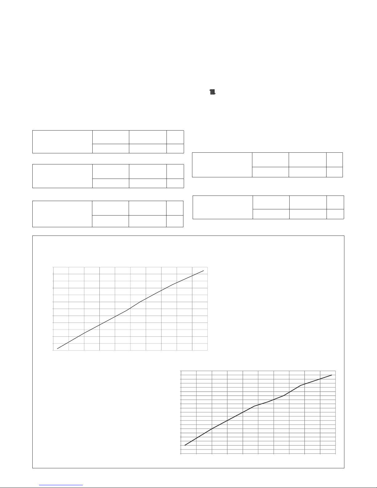
The boiler is supplied with the adjustments shown in the table. Depending on plant engineering requirements or regional ue gas emission limits it is,
however, possible to modify this value, referring to the graphs below.
HTGcurve(Qnheating)
COs.a.curve(Qnheating)
Heat output (kW)
Heat output (kW)
Fan rotations (rpm)
CO emissions s.a. (p.p.m.)
RANGE RATED
This boiler can be adapted to the plant’s thermal need, in fact, the maxi-
mum ow rate can be set for the boiler’s heating function:
- Disconnect the power supply to the boiler.
- Turn the heating water temperature selector to the maximum value.
- Lift and rotate the control panel towards you.
- Remove the cover by releasing the xing hooks.
- Insert jumper JP1 (g. 50).
- Put the power to the boiler on.
The three LEDs on the control panel ash alternately and an “ADJ” messa-
ge is shown on the display for about 4 sec, after which the maximum heating value can be changed using the heating temperature selector and CO
button (g. 37) to set and conrm the required value. The display shows
the icon . End the procedure by removing jumper JP1 to save the values
set in the memory.
Once the required (maximum heating) power is set indicate the value
on the instruction manual (see back cover). For subsequent checks and
adjustments, see the value set. Setting does not switch on the boiler. When
the heating setpoint selector knob is turned the display automatically shows
the number of rpm expressed in hundreds (e.g. 25 = 2500 rpm).
1200
1600
2000
2400
2800
3200
3600
4000
4400
4800
5200
5600
6000
812162024283236404448
table 5
SLOW IGNITION
METHANE
GAS(G20)
LIQUID GAS
(G31)
30 30 rpm

11
4.8 Gas conversion
Conversion from a family gas to other family gas can be performed easily
also when the boiler is installed.
This operation must be carried out by professionally qualied personnel.
The boiler is designed to operate with methane gas (G20) according to the
product label.
It is possible to convert the boiler to propane gas, using the special kit.
For disassembly, refer to the instructions below:
- remove power supply from the boiler and close the gas tap
- loosen the three xing screws of the upper cover, and the two lower screws
that x the casing
- remove the cover and casing
- remove the gas train (A) - g. 34
- remove the nozzle (B) - g. 34 - contained in the gas train, and replace it
with the one supplied
- reassemble the gas train
- re-power the boiler and turn on the gas tap
Conversionmustbecarriedoutbyqualiedpersonnel.
After conversion, adjust the boiler again (observing the “Adjust-
ments”section)andapplythenewidenticationlabelcontained
in the kit.
5 - MAINTENANCE
To ensure product characteristics and efciency remain intact and to comply with prescriptions of current regulations, it is necessary to render the
appliance to systematic checks at regular intervals.
When carrying out maintenance work, observe the instructions given in the
“Warnings and safety” chapter.
Turn off the appliance to carry out the maintenance of the structure near
the ue discharge connections or devices, and their accessories. Once
the interventions are completed, a qualied technician must check that the
pipes and the devices work correctly.
IMPORTANT: before carrying out any cleaning or maintenance operation
of the appliance, use the appliance and system switch to interrupt power
supply and close the gas supply turning the tap placed on the boiler.
Routine maintenance
This normally means the following tasks:
- removing any oxidation from the burner;
- removing any scale from the heat exchangers;
- removing any residue from the condensate drainage pipe;
- checking and cleaning the drainage pipes;
- checking the external appearance of the boiler;
- checking the ignition, switch-off and operation of the appliance, in both
domestic water mode and heating mode;
- checking the seal on the gas and water couplings and pipes;
- checking the gas consumption at maximum and minimum output;
- checking the position of the ignition-ame detection glowplug;
- checking the gas failure safety device.
Do not clean the appliance or its parts with easily inammable substances
(e.g. benzine, alcohol, etc.).
Do not clean panels, painted parts or plastic parts with paint thinner.
Panel cleaning must be carried out only with soapy water.
Extraordinary maintenance
These tasks restore appliance operation in accordance with the design and
regulations - e.g. following the repair of an accidental fault.
This normally means:
- replacement
- repair
- overhaul of components.
These tasks require special means, equipment and tools.
During the initial installation phase, or in the event of extraordinary
maintenance, you are advised to activate the procedure to discharge
air from the heating circuit and boiler (see the relevant paragraph).
5.1 Checking the combustion parameters
To carry out the combustion analysis, proceed as follows:
- loosen the three xing screws of the upper cover, and the two lower screws
that x the casing
- remove the cover and casing
- insert the analyser probes in the ue gas inlet (A) and air inlet (E) in the
boiler, after removing the screw B, the plug C and the plug D (g. 35).
Theuegasanalysisprobemustbefullyinsertedasfaraspos-
sible
- tighten the analyser sealing screw in the ue gas analysis inlet hole
- loosen the xing screws (E) on the instrument panel (g. 20)
- lift then turn the instrument panel towards you
- loosen the xing screws on the cover (F) to access the terminal board
(g. 22)
- press the “CO” button (g. 37)
Liveelectricalparts(230VAC).
- wait for burner ignition. The display shows “ACO”, the yellow LED ashes and the boiler operates at maximum heat output.
- check that the CO2 values match those given in the table, if the value
shown is different, change it as indicated in the chapter entitled “Gas
valve calibration”.
- perform the combustion check.
Then:
- remove the analyser probes and replace the plugs that you removed
earlier
- close the instrument panel and ret the housing.
IMPORTANT
Even during the combustion analysis phase, the function that switches the
boiler off when the water temperature reaches the maximum limit (about
90°C) remains enabled.
5.2 Serial number
Heating function
Qn Nominal heat delivery
Pn Nominal heat output
IP Degree of Protection
Pms Maximum heating pressure
T Temperature
NOx NOx class
Serial N.
230 V ~ 50 Hz W
Pms = bar T= °C
80-60 °C
50-30 °C
Qn = kW
Pn = kW
Pn = kW
12
USER GUIDE
1A GENERAL WARNINGS AND SAFETY
The instruction manual is an integral part of the product and it must therefore be kept carefully and must accompany the appliance; if the manual
is lost or damaged, another copy must be requested from the Technical
Assistance Service.
Boiler installation and any other assistance and maintenance opera-
tions must be carried out by qualied personnel according to the
provisions of local legislation.
For installation, it is advisable to contact specialised personnel.
The boiler must only be used for the application foreseen by the
manufacturer. The manufacturer shall not be liable for any damage
to persons, animals or property due to errors in installation, calibration, maintenance or due to improper use.
The safety and automatic adjustment devices must not be modied,
during the system life cycle, by the manufacturer or supplier.
This appliance produces hot water, therefore it must be connected
to a heating system and/or a domestic hot water mains, compatible
with its performance and output.
In case of water leakage, close the water supply and contact the
Technical Assistance Service immediately.
In case of absence for long periods time, close the gas supply and
switch off the electrical supply main switch. If there is a risk of frost,
drain the boiler.
From time to time check that the operating pressure of the hydraulic
system does not go below 1 bar.
In case of failure and/or malfunctioning, deactivate the appliance,
and do not try to repair or operate directly on it.
Appliance maintenance must be carried out at least once a year:
scheduling it with the Technical Assistance Service will avoid wasting
time and money.
Boiler use requires strict observation of some basic safety rules:
Do not use the appliance in any manner other than its intended
purpose.
It is dangerous to touch the appliance with wet or damp body parts
and/or when barefoot.
Under no circumstances cover the intake grids, dissipation grids
and ventilation vents in the installation room with cloths, paper or
any other material.
Do not use electrical switches, telephone or any other object that
causes sparks if there is a smell of gas. Ventilate the room by open-
ing doors and windows and close the central gas tap.
Do not place anything in the boiler.
Do not perform any cleaning operation if the appliance is not discon-
nected from the mains power supply.
Do not cover or reduce ventilation opening of the room where the
generator is installed.
Do not leave containers and inammable products in the installation
room.
Do not attempt to repair the appliance in case of failure and/or
malfunctioning.
It is dangerous to pull or twist the electric cables.
Children or unskilled persons must not use the appliance.
Do not carry out operations on sealed elements.
For better use, remember that:
- periodic external cleaning with soapy water not only improves its appearance but also preserves panelling from corrosion, extending its life cycle;
- if the wall-mounted boiler is enclosed in a hanging unit, leave at least 5
cm for ventilation and maintenance;
- installation of a room thermostat will greatly improve comfort, a more
rational use of the heat and energy saving; the boiler can also be connected to a programmable timer in order to control the switching on and
off of the appliance during the day or week.
2A SWITCHING ON THE APPLIANCE
Every time the appliance is powered up, a series of data is shown on the
display including the ue gas sensor meter reading (-C- XX) (see paragraph 4A - fault A09); the automatic purge cycle then starts, lasting around
2 minutes. During this phase, the three LEDs light up alternately and the
symbol is shown on the monitor (g. 36).
To start up the boiler it is necessary to carry out the following operations:
- power the boiler
- open the gas tap to allow the ow of fuel
- set the room thermostat to the required temperature (~20°C)
- turn the mode selector to the desired position:
Winter mode: turning the function selector (g. 38) within the area marked
+ and -, the boiler supplies hot water for heating and, if connected to an
external storage tank - supplies hot water for DHW.
If there is a heat request, the boiler switches on and the boiler status indica-
tor LED lights up with a xed green light. The digital monitor indicates the
heating water temperature (g. 40).
If there is a domestic hot water request, the boiler switches on and the
boiler status indicator LED lights up with a xed green light.
The display indicates the delivery temperature (g. 41).
Adjustment of the heating water temperature
To adjust the heating water temperature, turn the knob with symbol
(g. 38) clockwise to increase water temperature and anti-clockwise to
lower it.
Depending on the type of system, the most suitable temperature range can
be pre-selected:
- standard installations 40-80°C
- oor installations 20-45°C.
Adjusting the heating water temperature with an external probe connected
When an external probe is installed, the delivery temperature is automatically selected by the system, which quickly adjusts the ambient temperature according to variations in the outside temperature. If you want to alter
the temperature value (increasing or reducing the value automatically calculated by the electronic card), use the heating water temperature selector:
turn it clockwise to increase the temperature, or anticlockwise to reduce it.
The correction possibility is between -5 and +5 levels of comfort, shown on
the digital display by rotating the knob.
Summer mode only active when the external storage tank is connected:
turning the selector to the summer mode symbol (g. 39) activates the
traditional domestic hot water only function, the boiler supplies water at
the temperature set on the external storage tank.
If there is a domestic hot water request, the boiler switches on and the
boiler status indicator LED lights up with a xed green light. The display
indicates the delivery temperature (g. 41).
Adjustment of the domestic hot water temperature
CASE A heating only with storage tank - adjustment does not apply
CASE B heating only + external storage tank with thermostat - adjustment
does not apply.
CASE C heating only + external storage tank with probe - to adjust the
temperature of the domestic hot water in the storage tank, turn the knobbut with the symbol clockwise to increase water temperature and anticlockwise to lower it.
On the control panel, the green LED ashes with ON for 0.5 seconds, OFF
for 3.5 seconds.
The boiler is standby status until, after a heat request, the burner switches
on and the indicator LED turns xed green to indicate ame presence.
The boiler continues to operate until the temperatures set on the boiler are
reached, or the heat request is met; after which it goes back on standby.
If the red LED indicator near the symbol (g. 44) on the control panel
lights up, this means the boiler is in temporary shutdown status (see the
chapter “Light signals and faults”).
The digital monitor indicates the fault code detected.
S.A.R.A.functiong.45
Setting the heating water temperature selector in the zone marked by
AUTO, activates the automatic temperature control system (green led
ashing): according to the temperature set on the room thermostat and
the time taken to reach it, the boiler varies automatically the heating water
temperature reducing the operating time, allowing greater ease of opera-
tion and energy saving. On the control panel, the green LED ashes ON for
0.5 seconds, OFF for 3.5 seconds.
Reset function
To restore operation, set the mode selector to (g. 42), wait 5-6 seconds
then set the mode selector to the required position, checking that the red
indicator light is OFF.
At this point the boiler will automatically start and the red lamp switches
on in green.
N.B. If the attempt to reset the appliance does not activate operation, contact the Technical Assistance Service.
3A SWITCHING OFF
Temporary switch-off
In case of absence for short periods of time, set the mode selector (g.
42) to (OFF). In this way (leaving the electricity and fuel supplies enabled), the boiler is protected by the following systems:
Anti-frost device: when the temperature of the water in the boiler falls
below 5°C, the circulator and, if necessary, the burner are activated at minimum output levels to bring the water temperature back to the values for
safety (35°C). During the anti-frost cycle, the symbol (g. 46) appears
on the digital monitor.
13
Circulator anti-blocking function: an operation cycle is activated every
24 hours.
DHW Antifreeze (only when connected to an external storage tank
withprobe): the function is activated if the temperature measured by the
storage tank probe drops below 5° C. A heat request is generated in this
phase with the ignition of the burner at minimum power, which is maintained until the water temperature reaches 55° C. During the anti-frost cycle, the symbol (g. 46) appears on the digital monitor.
Switching off for long periods
In case of absence for long periods of time, set the mode selector (g. 42)
to (OFF).
Turn the main system switch OFF.
Close the fuel and water taps of the heating and domestic hot water system. In this case, anti-frost device is deactivated: drain the systems, in case
of risk of frost.
4A LIGHT SIGNALS AND FAULTS
The control panel has three LEDs that indicate the boiler operating status:
GREEN LED
Flashing
Flashing (0.5 seconds on, then 3.5 seconds off) = boiler in standby, there
is no ame.
Flashing (0.5 seconds on, then 0.5 seconds off) = temporary shutdown of
the appliance due to the following automatic-reset faults:
- water pressure switch (standby time 10 minutes approximately)
- transitory waiting for ignition.
In this phase, the boiler waits for restoration of working conditions. If after
the standby time, the boiler does not restore regular operation, the shutdown will be permanent and the signal light will be red.
Fast ashing (0.1 second on; then 0.1 second off; for 0.5 seconds) = Automatic Temperature Control System input/output function (g. 45).
Setting the heating water temperature selector in the zone marked by
AUTO (temperature value from 55 to 65°C) activates the Automatic Temperature Control System: the boiler varies the output temperature according to the closing signal of the room thermostat.
When the temperature set with the heating water temperature selector is
reached, a 20-minute countdown begins. If during this period the room
thermostat still requests heat, the value of the set temperature automatically increases by 5°C.
When the new value is reached, other 20-minute countdown begins. If during this period the room thermostat still requests heat, the value of the set
temperature automatically increases by 5°C. This new temperature value
is the result of the temperature set manually with the heating water temperature selector and the increase of +10°C of the Automatic Temperature
Control System (S.A.R.A.) function.
After the second cycle, the temperature value is not increased any further
(set temperature +10°C) and cycle described above is repeated until the
room thermostat request is met.
Fixed green
There is ame, the boiler works regularly.
RED LED
If the red LED lights up, this indicates the presence of a fault; the monitor
shows a code interpreted as follows:
Torestoreoperation(deactivatealarms):
Faults A 01-02-03
Position the function selector to (OFF), wait 5-6 seconds then set it to
the required position.
If the reset attempts do not reactivate the boiler, contact the Technical Assistance Centre.
Fault A04
In addition to the fault code, the digital display shows the symbol .
Check the pressure value indicated by the water gauge:
if it is less than 0.3 bar, position the function selector to (OFF) and adjust
the lling tap until the pressure reaches a value between 1 and 1.5 bar.
Then position the mode selector to the desired position.
The boiler will perform one purge cycle lasting approximately 2 minutes.
If pressure drops are frequent, request the intervention of the Technical
Assistance Service.
Fault A06
Contact the Technical Assistance Centre.
Fault A07
Contact the Technical Assistance Centre.
Fault A08
Contact the Technical Assistance Centre.
FaultA09withxedredLEDlit
Position the function selector to (OFF), wait 5-6 seconds then set it to
the required position.
If the reset attempts do not reactivate the boiler, request the intervention of
the Technical Assistance Service.
FaultA09withashingredandgreenLEDs
Contact the Technical Assistance Centre.
Fault A77
This is an automatic-reset fault, if the boiler does not restart, contact the
Technical Assistance Centre.
Flashing YELLOW LED
Combustion analysis in progress.
DESCRIPTION DISPLAY CODE RED LED YELLOW LED GREEN LED
Flame lockout/Water circulation failure (differential pressure
switch signal)
A01
ON OFF OFF
Limit thermostat intervention
A02
ashes OFF OFF
Fan fault
A03
ON OFF OFF
Water pressure switch fault
A04
ON OFF ON
Domestic hot water NTC probe fault
A06
ashes OFF ashes
Fault on heating delivery NTC probe or delivery-return differential circuit-breaker
A07
ON OFF OFF
Fault on heating return NTC probe or return-delivery differential circuit-breaker
A08
ON OFF OFF
Intervention of thermal safety device on ue gas probe
A09
ON OFF OFF
Flue gas NTC probe or heat exchanger cleaning
A09
ashes OFF ashes
Intervention of low temperature thermostat - general alarm
A77
ON OFF OFF
Combustion analysis procedure in progress
ACO
OFF ashes OFF

14
DESCRIPTION
MYNUTE GREEN 50 R.S.I.
Heating Nominal heat input in heating mode kW
47,00
kcal/h 40.420
Nominal heat output (80°/60°) kW
45,78
kcal/h
39.369
Nominal heat output (50°/30°) kW
49,91
kcal/h
42.926
Reduced heat input (G20/G31) kW
9,00/12,00
kcal/h
7.740/10.320
Reduced heat output (80°/60°) (G20/G31) kW 8,78/11,70
kcal/h 7.554/10.062
Reduced heat output (50°/30°) (G20/G31) kW
9,72/12,71
kcal/h 8.359/10.929
Nominal Range Rated heat output (Qn) kW 47,00
kcal/h
40.420
Minimum Range Rated heat output (Qn) (G20/G31) kW 9,00/12,00
kcal/h 7.740/10.320
Useful efciency Pn max - Pn min (80°/60°) (G20/G31) %
97,4-97,6 / 96,8-97,5
Useful efciency 30% (47° return) (G20/G31) % 102,5 / 100,1
Combustion performance via analysis socket % 97,0
Useful efciency Pn max - Pn min (50°/30°) (G20/G31) %
106,2-108,0 / 103,2-105,9
Useful efciency 30% (30° return) (G20/G31) %
108,0 / 106,2
Average Range Rated efciency Pn (80°/60°) % 97,6
Average Range Rated efciency Pn (50°/30°) %
106,9
Electric power W 162
Pump electric power (1.000 l/h) W
92
Category II2H3P
Country of destination (+)
Power supply voltage V - Hz 230 - 50
Degree of Protection IP X5D
Pressure drops at moment of stopping W 69
Pressure drops on ue with burner on % 3,00
Pressure drops on ue with burner at minimum % 1,30
Maximum quantity of condensate (50/30°C - CH4) l/min 5,2
Heating operation
Safety valve calibration pressure bar 3,5
Maximum operating pressure of heating circuit bar 4
Minimum pressure for standard operation bar 0,25 ÷ 0,45
Maximum temperature °C 90
Selection eld for H2O temperature in heating °C 20/45 ÷ 40/80
Pump: maximum capacity available for the system mbar 500
at an output of l/h 1.000
Water content in the heating circuit l 3,2
Gas pressure
Methane gas nominal pressure (G20) mbar 20
LPG liquid gas nominal pressure (G31) mbar 37
Hydraulic connections
Heating input - output Ø 1”
Gas input Ø 3/4”
Boiler dimensions
Height mm 764
Width mm 553
Depth of housing mm 284
Boiler weight kg 39
Flow rate G20 G31
Air capacity Nm3/h
58,533 59,694
Flue gas capacity Nm3/h 63,248 61,516
Mass ow of ue gas (max-min) gr/s 21,210-3,851 20,767-5,302
TECHNICAL DATA
(+) The installation of this product is allowed only in the destination Countries contained in the data plate, regardless of the present translation language.
15
* Check performed with concentric pipe ø 60-100, length 0.85m - water temperature 80-60°C
DESCRIPTION
Methane gas
(G20)
Propane
(G31)
Lower Wobbe index (at 15°C-1013 mbar) MJ/m3S 45,67 70,69
Net Caloric Value MJ/m3S 34,02 88
Supply nominal pressure mbar (mm W.C.) 20 (203,9) 37 (377,3)
Supply minimum pressure mbar (mm W.C.) 10 (102,0)
Diaphragm (number of holes) Number 1 1
Diaphragm (diameter of holes) mm 9,2 5,7
Heating maximum gas capacity Sm3/h 4,97
kg/h 3,65
Heating minimum gas capacity Sm3/h 0,95
kg/h 0,93
Number of fan rotations with slow switch-on
rpm 3.000 3.000
Maximum number of fan rotations (heating) rpm 5.800 5.700
Minimum number of fan rotations (heating) rpm 1.300 1.600
Multigas table
NOTE(iftheexternalprobeorthecontrolpanelorbothdevicesareintheboiler)
With reference to Delegated Regulation (EU) No. 811/2013, the data in the table can be used for completing the product card and the labelling for ambient
heating appliances, for mixed heating appliances, for assemblies of appliances for ambient heating, and for temperature control devices and solar devices:
COMPONENT Class Bonus
EXTERNAL PROBE II 2%
CONTROL PANEL V 3%
EXTERNAL PROBE + CONTROL PANEL VI 4%
DESCRIPTION
MYNUTE GREEN 50 R.S.I.
Fan performance
Residual head of concentric pipes 0.85m Pa
20
Residual head of separate pipes 0.5m Pa
196
Residual head of boiler without pipes Pa
199
Concentricuegasdischargepipes
Diameter mm
60-100
Maximum length m
1,85
Drop due to insertion of a 45°/90° bend m
1,3/1,6
Hole in wall (diameter) mm
105
Concentricuegasdischargepipes
Diameter mm
80-125
Maximum length m
4,85
Losses for a 45°/90° bend m
1/1,5
Hole in wall (diameter) mm
130
Separateuegasdischargepipes
Diameter mm
80
Maximum length m
20+20
Losses for a 45°/90° bend m
1/1,5
Installation B23P–B53P
Diameter mm
80
Maximum length of drainage pipe m
30
NOx class
class 5
Emission values at max. and min. rate of gas*
G20 G31
Maximum CO s.a. less than ppm
200 220
CO2 %
9,0 10,0
NOx s.a. lower than ppm
30 30
Flue gas temperature °C
78 75
Minimum CO s.a. less than ppm
20 40
CO2 %
9,5 10,0
NOx s.a. lower than ppm
25 30
Flue gas temperature °C
52 55
16
1 - AVERTISSEMENTS ET SÉCURITÉ
MANUEL D'INSTALLATION
FR
Les chaudières produites dans nos usines sont construites avec une
grande attention et chaque composant est contrôlé de manière à protéger les utilisateurs et les installateurs des blessures. Suite au travail
sur le produit, le personnel qualié doit contrôler les branchements
électriques, notamment les parties dénudées des conducteurs, qui ne
doivent dépasser du bornier, en évitant le contact possible avec les
parties sous tension dudit conducteur.
Ce manuel d'instructions fait partie intégrante du produit : s'assurer qu'il
accompagne toujours l'appareil, même en cas de cession à un autre
propriétaire ou utilisateur, ou bien en cas de mise en place sur une autre
installation. En cas de perte ou détérioration, veuillez en demander un
nouvel exemplaire au Service technique après-vente.
L'installation de la chaudière et toute autre opération d'assistance et
d'entretien doivent être effectuées par le personnel qualié selon les
dispositions des lois en vigueur.
Il est conseillé à l'installateur d'informer l'utilisateur sur le fonctionnement
de l'appareil et sur les règles fondamentales de sécurité.
Pour utiliser la fonction de protection antigel automatique de la chaudière
(pour températures inférieures à -1°C), basée sur le fonctionnement du
brûleur, l'appareil doit être en mesure de s'allumer. Cela signie que toute
condition de blocage (ex. manque de gaz ou d'alimentation électrique, ou
encore déclenchement d'un dispositif de sécurité) désactive la protection.
Cette chaudière ne peut s'utiliser que pour l'application pour laquelle elle
a été conçue. Le fabricant décline toute responsabilité contractuelle et
non contractuelle en cas de blessures à des personnes ou des animaux
ou en cas de dommages aux biens dérivés d'erreurs d'installation, de
réglage ou d'entretien, ou d'une utilisation inappropriée.
Une fois le produit déballé, s'assurer que tous ses composants sont
intacts et complets. Si tel n'est pas le cas, contacter le revendeur auprès
duquel vous avez acheté l'appareil.
La sortie de la vanne de sécurité doit être connectée à un système appro-
prié de récupération et de purge. Le fabricant décline toute responsabilité
en cas de dommages causés par toute opération menée sur la vanne
de sécurité.
Éliminer les matériaux d'emballage dans les récipients appropriés auprès
des centres de collecte autorisés.
Éliminer les déchets en ayant soin de ne pas menacer la santé et sans
faire appel à des procédures ou méthodes susceptibles d'endommager
l'environnement.
Durant l'installation, informer l'utilisateur que:
- en cas de fuites d'eau, il faut couper l'alimentation en eau et en informer
immédiatement le Service Technique Après-vente.
- il est nécessaire de vérier périodiquement que la pression de fonctionnement du système hydraulique est supérieure à 1 bar. Si nécessaire,
réinitialiser la pression comme indiqué dans le paragraphe intitulé
«Remplissage du système»
- En cas d'inactivité prolongée de la chaudière, il est recommandé
d'effectuer les opérations suivantes:
- placer l'interrupteur général de l'appareil et l'interrupteur général de
l'installation sur «off»
- fermer les robinets de combustible et d'eau de l'installation de chauffage
- vidanger l'installation de chauffage pour prévenir le gel.
En ce qui concerne la sécurité, il faut rappeler ce qui suit :
La chaudière ne doit pas être utilisée par des enfants ou des personnes
handicapées sans surveillance.
Il est dangereux d'activer des dispositifs ou des appareils électriques,
tels que des interrupteurs, des appareils électroménagers, etc. en cas
d'odeur de combustible ou de combustion. En cas de fuites de gaz, aérer
la pièce en ouvrant complètement les portes et les fenêtres ; fermer le
robinet général de gaz ; contacter immédiatement le Service Thecnique
Après-vente ou le personnel qualié
Ne pas toucher la chaudière à pieds nus ou avec des parties du corps
mouillées ou humides.
Avant toute opération de nettoyage, débrancher la chaudière de l'alimen-
tation générale en tournant l'interrupteur de l'installation à deux positions
et l'interrupteur général du panneau de commande sur « OFF »
Il est interdit de modier les dispositifs de sécurité ou de réglage sans
l'autorisation ou les indications du fabricant.
Ne pas tirer, débrancher ou tordre les câbles électriques ressortant de
la chaudière, même lorsqu'elle n'est pas reliée au secteur.
Dans certaines parties du manuel, les symboles suivants sont employés :
ATTENTION = actions demandant une certaine prudence et une prépa-
ration adéquate.
INTERDICTION = actions NE DEVANT ABSOLUMENT PAS être exécutées.
Éviter de boucher ou de réduire les dimensions des ouvertures d'aération
de la pièce où l'appareil est installé.
Ne pas laisser des récipients ni de substances inammables dans la
pièce où l'appareil est installé.
Ne pas laisser les éléments d'emballage à la portée des enfants.
Il est interdit de bloquer l'évacuation des condensats.
2 - DESCRIPTION
MYNUTE GREEN 50 R.S.I. est une chaudière à condensation murale de type C
en mesure de fonctionner en différentes conditions à travers une série de cavaliers sur la carte électronique (comme décrit dans «Conguration de la chaudière»):
CAS A
chauffage uniquement sans branchement à un chauffe-eau extérieur.
La chaudière ne fournit pas d'eau chaude sanitaire.
CAS B
chauffage uniquement avec branchement à un chauffe-eau extérieur à commande thermostatique: dans cette condition, avec toute demande de chaleur du
thermostat du chauffe-eau, la chaudière fournit de l'eau chaude pour la préparation de l'eau chaude sanitaire.
CAS C
chauffage seul avec un chauffe-eau extérieur raccordé (kit accessoire disponible sur demande) (géré par une sonde de température) pour la préparation
de l'eau chaude sanitaire. Lors du branchement du chauffe-eau non fourni par
notre société, s'assurer que la sonde NTC dispose des caractéristiques suivantes : 10 kohm à 25 °C, B 3435 ±1 %.
En fonction des fumées utilisés, la chaudière est classée dans les catégories suivantes B23P;B53P; C13,C13x; C23; C33,C33x; C43,C43x; C53,C53x;
C63,C63x; C83,C83x; C93,C93x.
Dans la conguration B23P/B53P (en cas d'installation à l'intérieur), l'appareil ne
peut pas être installé dans des pièces utilisées comme chambre à coucher, salle
de bain, douche ou possédant des cheminées ouvertes sans afux d'air propre.
La pièce où la chaudière sera installée devra avoir une ventilation appropriée.
Dans la conguration C, l'appareil peut être installé dans n'importe quel type de pièce
car il n'existe aucune limite quant aux conditions d'aération et au volume de la pièce.
Les caractéristiques techniques principales de l'appareil sont les suivantes:
- Brûleur à prémélange à faible émission.
- Carte à microprocesseur qui commande les entrées, les sorties et la gestion
des alarmes.
- Modulation électronique continue de la amme en mode chauffage.
- Allumage électronique avec commande à ionisation de amme.
- Ventilateur en courant continu commandé par compte-tours à effet Hall.
- Stabilisateur de pression du gaz incorporé.
- Sonde NTC pour le contrôle de la température de refoulement du primaire.
- Sonde NTC pour le contrôle de la température de retour du primaire.
- Dispositif pour la séparation et la purge automatique de l'air.
- Vanne 3 voies à actionneur électrique (en accessoire).
- Pressostat eau.
- Hydromètre de visualisation de la pression d'eau de chauffage.
- Dispositif antiblocage du circulateur.
- Chambre de combustion étanche par rapport à l'environnement.
- Robinet du gaz électrique à double obturateur qui commande le brûleur.
- Sonde extérieure de thermorégulation (en accessoire).
- Autodiagnostic pour l'indication de nettoyage de l'échangeur primaire.
- Circulateur
- Range Rated: la chaudière est équipée d'un dispositif d'adaptation au
besoin thermique de l'installation qui permet de régler, selon les demandes
d'énergie du bâtiment, le débit de la chaudière.
Les dispositifs de sécurité de l'appareil sont les suivants:
- Thermostat limite d'eau qui contrôle les surchauffes de l'appareil, tout en
garantissant la sécurité intégrale de l'ensemble de l'installation. Pour rétablir
le fonctionnement en cas d'intervention du thermostat limite, appuyer sur le
bouton placé à droite, sous la console de la chaudière.
- Sonde de fumées - celle-ci intervient (en réglant la chaudière en mode arrêt
de sécurité) lorsque la température des produits de la combustion dépasse la
température de service maximale des conduits d'évacuation.
- Vanne de sécurité à 3,5 bar.
- Commande par microprocesseur de la continuité des sondes avec indication
sur afcheur des anomalies éventuellement présentes.
- Siphon pour l'évacuation des condensats avec otteur qui empêche la sortie
des fumées.
- Capteur de niveau des condensats qui bloque la chaudière si le niveau des
condensats dans l'échangeur dépasse la limite admissible.
- Fonction antigel de premier niveau (pour une température max. du lieu
d'installation de -1 °C), assurée par la sonde NTC de chauffage.

17
- Fonction antigel de deuxième niveau (pour une température max. du lieu
d'installation de -15 °C), assurée par un kit de résistance électrique qui empêche
la congélation des condensats dans la chaudière.
- Diagnostic du manque de circulation effectué par la comparaison des
températures lues par les sondes de refoulement et de retour.
- Pressostat différentiel qui autorise l'allumage du brûleur si une circulation
minimale d'eau est garantie dans l'échangeur primaire.
- Diagnostic du manque d'eau effectué par le capteur de pression.
- Système de sécurité pour l'évacuation des fumées basé sur le principe de
fonctionnement pneumatique du robinet du gaz.
- Diagnostic de surchauffe effectué sur le refoulement et sur le retour avec
double sonde (température limite 95 °C).
- Contrôle du ventilateur par un dispositif compte-tours à effet Hall: la vitesse
de rotation du ventilateur est ainsi surveillée en permanence.
La chaudière est prévue pour la connexion des dispositifs suivants:
- vanne à 3 voies extérieure,
- circulateur supplémentaire,
- thermostat d'ambiance ou programmateur horaire,
- sonde extérieure de régulation thermique,
- commande à distance,
- thermostat de sécurité pour des installations à basse température,
- thermostat ou sonde du chauffe-eau à distance.
3 - INSTALLATION
3.1 Normes pour l'installation
L'installation doit être effectuée par le personnel qualié, conformément aux
réglementations locales.
LIEU D'INSTALLATION
La chaudière peut fonctionner dans une plage de température de -15 °C à +60 °C.
SYSTÈME ANTIGEL
La chaudière est équipée de série d'un système antigel automatique qui s'active
lorsque la température de l'eau du circuit primaire est inférieure à 6 °C.
Ce système est toujours actif et il garantit la protection de la chaudière jusqu'à
une température du lieu d'installation de -1 °C.
Pour utiliser cette protection, basée sur le fonctionnement du brûleur, la
chaudière doit être en mesure d'être allumée, car toute condition de blocage (ex. manque de gaz ou d'alimentation électrique, ou bien intervention
d'un dispositif de sécurité) désactive la protection.
S'il est nécessaire de protéger la chaudière jusqu'à une température du lieu
d'installation de -15 °C, il faut utiliser le kit antigel spécique qui empêche
la congélation des condensats dans la chaudière.
Pour employer la protection antigel, une alimentation électrique est néces-
saire. Tout manque d'alimentation désactive la protection.
La protection antigel est active même lorsque la chaudière est en état de
veille.
Dans des conditions normales de fonctionnement, la chaudière est capable de
s'autoprotéger du gel.
Pour la protection antigel de la chaudière, il est conseillé d'utiliser un liquide
antigel de qualité dans le circuit primaire, an d'éviter le risque de congélation,
dans des zones soumises à des températures inférieures à 0 °C, ou bien au cas
où l'appareil serait laissé longtemps hors tension et qu'on ne souhaiterait pas
vidanger l'installation de chauffage.
Suivre attentivement les instructions du fabricant concernant non seulement le
pourcentage de liquide antigel à utiliser pour la température minimale à laquelle vous
souhaitez maintenir le circuit de la machine mais également la durée et le mode d'élimination du liquide antigel. Pour la partie sanitaire, il est conseillé de vider le circuit.
Les matériaux utilisés pour la fabrication des composants des chaudières sont
résistants aux liquides antigel à base de glycols éthyléniques.
DISTANCES MINIMALES
Pour accéder à l'intérieur de la chaudière an d'effectuer les opérations normales d'entretien, il est nécessaire de respecter les espaces minimaux prévus
pour l'installation (g. 16a).
Pour un positionnement correct de l'appareil, il faut tenir compte des aspects suivants :
- il ne doit pas être placé sur une cuisinière ou un autre appareil de cuisson ;
- il est interdit de laisser des substances inammables dans la pièce où la chau-
dière est installée ;
- les murs sensibles à la chaleur (par exemple ceux en bois) doivent être pro-
tégés à l'aide d'une isolation convenable.
IMPORTANT
Avant l'installation, il est conseillé de laver soigneusement tous les tuyaux du
système an de retirer d'éventuels résidus qui pourraient compromettre le bon
fonctionnement de l'appareil.
Brancher le collecteur de purge à un système d'évacuation approprié (pour plus
d'informations, consulter le chapitre 3.6). Le circuit de l'eau sanitaire n'a pas besoin de soupape de sécurité, mais il faut s'assurer que la pression du conduit
d'eau ne dépasse pas 6 bars. En cas de doute, il sera convenable d'installer un
réducteur de pression. Avant d'allumer la chaudière, s'assurer que celle-ci est
prévue pour fonctionner avec le gaz disponible. ceci peut être repéré dans l'inscription sur l'emballage et dans l'étiquette adhésive reportant le type de gaz. Il
est très important de signaler que dans certains cas les conduits de fumées sont
sous pression, donc les jonctions de plusieurs éléments doivent être hermétiques.
3.2 Nettoyage du système et caractéristiques de l'eau
du circuit de chauffage
En cas d'une nouvelle installation ou d'un remplacement de la chaudière, il faut
effectuer un nettoyage préventif de l'installation de chauffage.
Il est conseillé de monter sur l’installation un ltre pour la récupération et la
séparation des impuretés (ltre de décantation).
An de garantir le bon fonctionnement du dispositif, ajouter les additifs et/ou
traitements chimiques (ex. liquides antigel, agents protecteurs, etc.), et vérier
si les paramètres du tableau respectent les valeurs indiquées.
Paramètres Unité de
mesure
Circuit d'eau
chaude
sanitaire
Remplissage
d'eau
valeur pH 7–8
-
Dureté °F
-
15–20
Aspect
- clair
3.3 Fixation de la chaudière au mur et raccordements
hydrauliques
Avant d'effectuer l'installation, vérier la présence des espaces nécessaires
pour la réalisation de l'installation, tout en considérant les dimensions de la
chaudière, du système d'évacuation des fumées et du circuit hydraulique.
La chaudière est fournie de série avec la plaque de support F (g.16). La position
et la dimension des raccords hydrauliques sont indiquées en détail. En outre, un
gabarit en carton est fourni avec la chaudière pour aider l'installateur.
Pour le montage, effectuer les opérations suivantes :
- xer la plaque de support de la chaudière au mur et contrôler si elle est
parfaitement horizontale à l'aide d'un niveau à bulle ;
- tracer les 4 trous prévus pour la xation de la plaque de support de la chaudière ;
- vérier si toutes les mesures sont exactes, puis percer le mur en utilisant une
perceuse dotée de mèche du diamètre indiqué plus haut ;
- xer la plaque au mur.
Pour le montage des accessoires se rapporter aux instructions contenues avec
l'équipement standard.
Effectuer les raccordements hydrauliques et installer l'évacuation de la vanne de
sécurité et du robinet à 3 voies (si installé).
Le constructeur n'est pas responsable des dommages causés en cas de
non branchement des évacuations des dispositifs en objet.
Effectuer les raccords hydrauliques.
3.4 Installation du couvercle supérieur
Installer le couvercle supérieur et le xer à la chaudière avec les vis A (g. 17)
fournies de série.
Le montage du couvercle doit être effectué avant l'installation du système
d'aspiration et d'évacuation des fumées.
Lors de chaque démontage du manteau, dévisser les 3 vis de xation du
couvercle supérieur.
Le fabricant décline toute responsabilité pour des dommages dérivés du
manque d'installation des couvercles.
3.5 Installationducapteurextérieur(g.19)
Le bon fonctionnement de la sonde extérieure est fondamental à celui du
contrôle climatique.
INSTALLATION ET BRANCHEMENT DU CAPTEUR EXTÉRIEUR
Installer le capteur sur un mur extérieur de l'édice à chauffer, en observant les
indications suivantes:
monter le capteur sur la façade la plus fréquemment exposée au vent (sur le
mur orienté vers le NORD ou le NORD-OUEST), à l'abri du rayonnement solaire
direct; le monter à environ 2/3 de la hauteur de la façade;
ne pas le monter près des portes, fenêtres, orices d'évacuation des conduits
d'air, conduits de fumées ou autres sources de chaleur.
Le branchement électrique au capteur extérieur doit être effectué avec un câble
bipolaire d'une section de 0,5 à 1mm2 (non fourni de série), d'une longueur
maximale de 30 mètres. La polarité du câble de connexion au capteur extérieur
n'a aucune importance. Éviter d'effectuer des jonctions sur ce câble; au cas où
celles-ci seraient nécessaires, elles doivent être étanches et bien protégées.
Toute canalisation du câble de connexion éventuellement nécessaire doit être
séparée des câbles sous tension (230 Vac).
FIXATION AU MUR DU CAPTEUR EXTÉRIEUR
Installer le capteur sur une partie lisse du mur; En cas de briques apparentes
ou des murs irréguliers, il faut prévoir une zone de contact de préférence lisse.
Dévisser le couvercle de protection supérieur en plastique en le tournant dans
le sens inverse des aiguilles d'une montre.
Identier le lieu de xation au mur et réaliser le perçage pour la cheville à expansion de 5x25.
Insérer la cheville dans le trou. Retirer la carte de son siège.
Fixer le boîtier au mur en utilisant la vis fournie de série.
Accrocher la bride et serrer la vis.
Dévisser l'écrou du passe-câble, introduire le câble de connexion du capteur et
le brancher à la borne électrique.

18
Pour le branchement électrique du capteur extérieur à la chaudière, consulter le
chapitre « Branchements électriques ».
Ne pas oublier de bien fermer le passe-câble pour éviter que l'humidité
de l'air entre son ouverture.
Replacer la carte dans son siège.
Fermer le couvercle de protection supérieur en plastique en le tournant dans le
sens des aiguilles d'une montre. Serrer fermement le passe-câble.
3.6 Récupération des condensats
L'installation doit être réalisée de manière à éviter la congélation des condensats
produits par la chaudière (ex. en l'isolant). Il est conseillé d'installer un col-
lecteur d'évacuation spécial en polypropylène (disponible sur le marché) sur
la partie inférieure de la chaudière (trou Ø 42) comme indiqué dans la gure 18.
Placer le tuyau exible d'évacuation des condensats fourni avec la chaudière et le
connecter au collecteur (ou autre dispositif de raccordement pouvant être inspecté)
en évitant de créer des courbes où la condensation pourrait stagner et éventuellement geler. Le fabricant décline toute responsabilité pour des dommages éventuellement causés par le manque d'écoulement de la condensation ou par sa congélation. La ligne de connexion de l'évacuation doit être parfaitement étanche et
convenablement protégée contre le risque de gel. Avant la mise en service de
l'appareil, s'assurer que la condensation puisse être évacuée correctement.
3.7 Raccordement de gaz
Le raccordement du gaz doit être réalisé dans le respect des règles d'installation
en vigueur et dimensionné an de garantir le débit correct du gaz au brûleur.
Avant de réaliser le raccordement, vérier ce qui suit :
- si le type de gaz est celui pour lequel l'appareil a été prévu,
- si les tuyaux sont propres.
Il est conseillé d'installer un ltre de dimensions appropriées sur la ligne de gaz
au cas où le réseau de distribution contiendrait des particules solides.
Une fois l'installation effectuée, vérier si les jonctions réalisées sont étanches
comme prévu par les règles d'installation en vigueur.
3.8 Branchements électriques
Pour accéder aux branchements électriques, procéder comme suit.
Pour accéder au bornier:
- éteindre l'interrupteur général du système
- dévisser les vis de xation (D) sur le logement (g. 20)
- déplacer la base du logement vers l'avant puis vers le haut an de la décro-
cher du châssis
- dévisser la vis de xation (E) du panneau de commande (g. 20)
- lever puis tourner le panneau de commande vers soi
- dévisser la vis de xation du boîtier des connexions électriques puis retirer ce
dernier de son logement.
Le boîtier présente un côté réservé aux connexions électriques à haute tension
(230 V) et un côté réservé aux connexions électriques à basse tension (g.
23-24).
Se référer aux schémas électriques correspondants pour effectuer les connexions.
Le branchement au réseau électrique doit être réalisé par un dispositif de
séparation avec ouverture omnipolaire d'au moins 3,5 mm (EN 60335-1,
catégorie III). L'appareil fonctionne en courant alternatif sur 230 V/50 Hz et il est
conforme à la norme EN 60335-1. Il faut effectuer la connexion avec une mise
à la terre sûre, selon les normes en vigueur.
En plus, il est conseillé de respecter le branchement phase-neutre (L-N).
Le conducteur de terre doit être deux centimètres plus long que les autres.
La chaudière peut fonctionner avec une alimentation phase-neutre ou phasephase. Pour des alimentations sans mise à la terre, il faut utiliser un transformateur
d'isolement avec le secondaire mis à la terre.
L'utilisation des tuyaux de gaz et/ou d'eau comme mise à la terre
d'appareils électriques est interdite.
Entrée de thermostat d'ambiance à basse tension (24V DC).
L'installateur est responsable d'assurer une mise à la terre appropriée de
l'appareil. Le fabricant décline toute responsabilité pour des dommages
éventuellement causés par l'absence ou par la mauvaise réalisation de
la mise à la terre.
Pour le branchement de la chaudière au secteur, utiliser le câble d'alimentation
fourni. En cas de remplacement du câble d'alimentation, utiliser un câble
du type HAR H05V2V2-F, 3 x 0,75 mm2, diamètre extérieur max. de 7 mm.
THERMOSTAT
DE SÉCURITÉ
PRESSOSTAT
DE SÉCURITÉ
CHAUDIÈRE
AVERTISSEMENTS:
- Pour le branchement électrique du pressostat et du thermostat de sécurité
I.S.P.E.S.L. (si installé), suivre les indications du schéma en annexe.
3.9Remplissagedel'installationdechauffage
Une fois les raccords hydrauliques réalisés, il est possible de remplir l'installation
de chauffage.
Cette opération doit être réalisée quand l'installation est froide en suivant les
instructions suivantes :
- Ouvrir le bouchon du purgeur automatique d'air de la chaudière (A) - g. 31
en l'ouvrant de deux ou trois tours; pour permettre une sortie continue de
l'air, laisser le bouchon ouvert.
- Ouvrir les purgeurs des radiateurs.
- Ouvrir le robinet de remplissage (à l'extérieur de la chaudière) jusqu'à ce que
la pression indiquée par l'hydromètre soit comprise entre 1,5 bar et 2 bar. Il
faut réaliser le remplissage lentement pour libérer les bulles d'air contenues
dans l'eau et pour permettre leur sortie par les trous de purge de la chaudière
et de l'installation de chauffage. Pour les opérations d'élimination de l'air, se
référer au paragraphe spécique.
- Refermer le robinet de remplissage
- Fermer les purgeurs des radiateurs quand seulement de l'eau sortira de celles-ci.
ATTENTION: la chaudière n'est pas équipée de vase d'expansion. Il est donc
obligatoire de monter un vase fermé sur l'installation pour garantir le bon fonctionnement de l'appareil.
Les dimensions du vase d'expansion doivent être adaptées aux caractéristiques
de l'installation de chauffage. En outre, la capacité du vase doit répondre aux
exigences des normes en vigueur.
Si la pression arrive à des valeurs proches de 3,5 bar, il existe le risque d'intervention de la vanne de sécurité. Dans ce cas-là, demander l'intervention du
personnel professionnellement qualié.
Vidange de l'installation de chauffage
Avant de commencer la vidange, couper l'alimentation électrique en plaçant
l'interrupteur général de l'installation sur «éteint».
- Fermer les robinets de l'installation thermique.
- Desserrer manuellement la vanne d'évacuation de l'installation (B) - g. 32 -
et brancher le tuyau (fourni avec la chaudière) pour évacuer l'eau dans un
récipient extérieur.
3.10 Purge d'air du circuit de chauffage et de la
chaudière
Lors de la première installation ou en cas d'entretien extraordinaire, il est recommandé de réaliser les opérations suivantes :
1. À l'aide d'une clé CH11, ouvrir la vanne manuelle de purge d'air placée au-
dessus du caisson d'air (g. 15). Il faut connecter au purgeur le tuyau fourni
avec la chaudière pour pouvoir décharger l'eau dans un récipient extérieur.
2. Ouvrir le robinet de remplissage de l'installation situé sur l'unité hydraulique
et attendre que l'eau commence à s'écouler de la vanne.
3. Mettre la chaudière sous tension tout en laissant fermé le robinet du gaz.
4. Activer une demande de chaleur au moyen du thermostat d'ambiance ou du
panneau de commande à distance, pour que la vanne à 3 voies se place en
mode chauffage.
5. Activer une demande d'eau chaude sanitaire comme suit :
chaudières à chauffage uniquement branchées à un chauffe-eau exté-
rieur: activer le thermostat sur le chauffe-eau.
6. Continuer la séquence jusqu'à ce que l'écoulement de l'eau uniquement
sorte de la vanne manuelle de purge d'air et que le débit d'air se soit arrêté.
Fermer le purgeur d'air manuel.
7. Vérier si la pression dans l'installation est correcte (la pression idéale est
1 bar).
8. Fermer le robinet de remplissage de l'installation.
9. Ouvrir le robinet du gaz et allumer la chaudière.
3.11 Circulateur
Les chaudières sont équipées d'un circulateur (déjà raccordé hydrauliquement
et électriquement) dont les performances utiles sont illustrées dans le graphique.
Les chaudières sont équipées d'un système antiblocage qui démarre un cycle
de fonctionnement toutes les 24 heures d'arrêt avec sélecteur de fonction
dans n'importe quelle position.
La fonction «antiblocage» n'est active que si les chaudières sont sous
tension.
Il est formellement interdit de faire fonctionner le circulateur sans eau.
Débit d'eau maximum autorisé <2200 l/h.
Dans la chaudière, il faut garantir un débit minimum de 800 l/h an
d'éviter l'intervention du pressostat différentiel.
Pour brancher l'installation, l'utilisation d'un séparateur hydraulique est
recommandée (fourni comme accessoire), branché comme illustré dans
les diagrammes (g. 8-9).

19
longueur rectiligne du conduit coaxial ø80-125 mm perte de charge
courbe 45° courbe 90°
4,85 m 1 m 1,5 m
Conduitsdédoublés(Ø80mm)-g.28-29
Les conduits dédoublés peuvent être orientés dans la direction la plus adaptée
aux exigences de l'installation.
Pour l'installation, suivre les instructions fournies avec le kit de l'accessoire
spécique pour chaudières à condensation.
Prévoir une inclinaison du conduit d'évacuation des fumées de 3° vers
la chaudière.
La chaudière adapte automatiquement la ventilation au type d'installation
et à la longueur des conduits. Ni obstruer ni réduire en aucune façon les
conduits.
L'utilisation de conduits d'une longueur supérieure comporte une perte
de puissance de la chaudière.
La «longueur rectiligne» est exprimée sans courbes, terminaux d’évacuation
ni jonctions.
longueur maximale rectiligne conduits dédoublés
ø 80 mm
perte de charge
courbe 45° courbe 90°
20 + 20 m 1 m 1,5 m
3.12 Évacuation des fumées et aspiration d'air
Observer la législation locale concernant l'évacuation des fumées.
L'évacuation des produits de la combustion est assurée par le ventilateur centrifuge monté sur la chaudière.
La chaudière est fournie sans le kit d'évacuation des fumées/aspiration d'air, car
il est possible d'utiliser les accessoires pour des appareils à chambre étanche à
tirage forcé qui mieux s'adaptent aux caractéristiques typologiques d'installation.
Pour l'extraction des fumées et le rétablissement de l'air comburant de la chaudière, il est indispensable que seuls les tuyaux originaux fabriqués par notre
usine, spéciques pour des chaudières à condensation, soient employés et que le
raccordement soit effectué correctement, tel qu'il est indiqué dans les instructions
fournies avec les accessoires pour fumées.
La chaudière est un appareil de type C (à chambre étanche) et doit donc disposer
d'une connexion sûre vers le conduit d'évacuation des fumées et vers le conduit
d'aspiration de l'air comburant; aboutissant tous les deux à l'extérieur et sans
lesquels l'appareil ne peut fonctionner.
Les types de terminaux disponibles peuvent être coaxiaux ou dédoublés.
Les longueurs maximales des conduits de fumées se rapportent à des
systèmes disponibles dans le catalogue.
La chaudière est conçue pour recevoir et éliminer par son siphon les
condensats des fumées et/ou des eaux météoriques provenant du système
d'évacuation des fumées, au cas où un siphon extérieur n'aurait pas été
prévu en phase d'installation et/ou de conception.
ATTENTION: en cas d'installation d'une pompe d'évacuation des
condensats, vérier les données techniques sur le débit fournies par le
fabricant an de garantir son bon fonctionnement.
INSTALLATION«ÀOUVERTUREFORCÉE»(TYPEB23P-B53P)-g.25
Conduitd'évacuationdesfumées(ø80mm)
Pour disposer de cette conguration, il faut employer le tronçon spécique fourni
comme accessoire.
Pour l'installation, suivre les instructions fournies avec les kits.
Dans ce cas-là, l'air comburant est prélevé de la pièce où la chaudière
est installée, qui doit être un local techniquement approprié et muni d'une
aération adéquate.
Les conduits d'évacuation des fumées non isolés constituent des sources
potentielles de danger.
Prévoir une inclinaison du conduit d'évacuation des fumées d 3° vers la
chaudière.
longueur maximale du conduit d'évacuation des
fumées ø 80 mm
perte de charge
courbe 45° courbe 90°
30 m 1 m 1,5 m
La «longueur rectiligne» est exprimée sans courbes, terminaux d'évacuation
ni jonctions.
Tuyauxconcentriques(Ø80-125mm)-g.27
Pour pouvoir connecter les conduits coaxiaux, il faut employer l'adaptateur spécique fourni comme accessoire. Les conduits coaxiaux peuvent être orientés dans
la direction la plus appropriée aux exigences de l'installation, mais il faut prêter
beaucoup d'attention à la température extérieure et à la longueur du conduit.
Prévoir une inclinaison du conduit d'évacuation des fumées de 3° vers la
chaudière.
Les conduits d'évacuation non isolés constituent des sources potentielles
de danger.
La chaudière adapte automatiquement la ventilation au type d'installation
et à la longueur du conduit.
Ni obstruer ni réduire en aucune façon le conduit d'aspiration de l'air comburant.
Pour l'installation, suivre les instructions fournies avec les kits.
INSTALLATION ÉTANCHE (TYPEC)
La chaudière doit être connectée aux conduits d'évacuation des fumées et d'aspiration d'air coaxiaux ou dédoublés, lesquels devront déboucher à l'extérieur. Il est
interdit de faire fonctionner la chaudière sans ces conduits connectés.
Tuyauxconcentriques(Ø60-100mm)-g.26
Pour pouvoir connecter les conduits coaxiaux, il faut employer l'adaptateur spécique fourni comme accessoire. Les conduits coaxiaux peuvent être orientés dans
la direction la plus appropriée aux exigences de l'installation, mais il faut prêter
beaucoup d'attention à la température extérieure et à la longueur du conduit.
longueur rectiligne du conduit
coaxial ø 60-100 mm
Horizontal Vertical
perte de charge
courbe 45° courbe 90°
1,85 m 2,85 m 1,3 m 1,6 m
Débit(l/h)
Hauteurdechargerésiduelle(m.C.E.)
0,00
0,50
1,00
1,50
2,00
2,50
3,00
3,50
4,00
4,50
5,00
5,50
6,00
6,50
7,00
0100 200300 400500 600700 800 9001000 11001200 13001400 15001600 17001800 19002000
Prévoir une inclinaison du conduit d'évacuation des fumées de 3° vers la
chaudière.
Les conduits d'évacuation non isolés constituent des sources potentielles
de danger.
La chaudière adapte automatiquement la ventilation au type d'installation
et à la longueur du conduit.
Ni obstruer ni réduire en aucune façon le conduit d'aspiration de l'air
comburant.
Pour l'installation, suivre les instructions fournies avec les kits.

20
4 - ALLUMAGE ET FONCTIONNEMENT
4.1 Allumage de l'appareil
Chaque fois que l'appareil est mis sous tension, une série de données s'afche
sur l'écran indiquant la lecture du débitmètre du capteur de fumées (-C- XX)
(voir paragraphe 4.3 - anomalie A09); le cycle de purge automatique débute
alors et dure environ 2 minutes. Au cours de cette phase, les trois LED s'allument en alternance et le symbole s'afche sur le moniteur (g. 36).
Pour interrompre le cycle de purge automatique, procéder comme suit:
accéder à la carte électronique en retirant le logement, en tournant le tableau de
bord vers soi et en ouvrant le capot de la carte.
Ensuite:
- appuyer sur le bouton CO (g. 37).
Partiesélectriquessoustension(230VAC).
Pour allumer la chaudière, effectuer les opérations suivantes:
- mettre la chaudière sous tension
- ouvrir le robinet de gaz an de permettre le ux du combustible
- régler le thermostat d'ambiance à la température requise (~20°C)
- tourner le sélecteur de fonction sur la position souhaitée:
Mode hiver: en tournant le sélecteur de fonction (g. 38) dans la zone marquée
+ et -, la chaudière produit de l'eau chaude pour le chauffage et de l'eau chaude
sanitaire, si un chauffe-eau extérieur est raccordé.
En cas de demande de chaleur, la chaudière s'allume et le LED d'indication de
l'état de la chaudière s'allume en vert. Le moniteur afche la température de
refoulement (g. 40).
En cas de demande d'eau chaude sanitaire, la chaudière s'allume et le LED
d'indication de l'état de la chaudière s'allume en vert.
L'écran indique la température de l'eau chaude sanitaire (g. 41).
Réglage de la température de l'eau de chauffage
Pour régler la température de l'eau du chauffage, tourner la poignée avec le
symbole (g. 38); dans le sens des aiguilles d'une montre, la température augmente, dans le sens inverse, elle diminue.
En fonction du type de système, sélectionner la plage de température la plus adaptée:
- installations standard 40-80°C
- installations au sol 20-45°C.
Pour plus d'informations, consulter le paragraphe «Conguration de la chaudière».
Réglage de la température de l'eau de chauffage avec sonde extérieure
connectée
Quand une sonde extérieure est connectée, la valeur de la température de refoulement est choisie automatiquement par le système, qui adapte rapidement
la température ambiante en fonction des variations de la température extérieure.
Si l'on veut modier la valeur de la température, en l'augmentant ou en la diminuant par rapport à celle calculée automatiquement par la carte électronique, il
est possible d'agir sur le sélecteur de température de l'eau de chauffage : dans
le sens des aiguilles d'une montre, la valeur de correction de la température
augmente ; dans le sens inverse, elle diminue.
La possibilité de correction se situe entre les niveaux de confort -5 et +5, afchés sur l'écran numérique en tournant la poignée.
Mode été activé uniquement lorsqu'un chauffe-eau extérieur est branché: en
tournant le sélecteur sur le symbole de mode été (g. 39) on active la fonc-
tion traditionnelle eau chaude sanitaire uniquement, la chaudière produit de
l'eau à la température réglée sur le chauffe-eau extérieur.
En cas de demande d'eau chaude sanitaire, la chaudière s'allume et le LED
d'indication de l'état de la chaudière s'allume en vert. Le moniteur afche la
température de refoulement (g. 41).
Réglage de la température de l'eau chaude sanitaire
CAS A chauffage uniquement - le réglage n'est pas nécessaire.
CAS B chauffage uniquement + chauffe-eau extérieur avec thermostat - le ré-
glage n'est pas nécessaire.
CAS C chauffage uniquement + chauffe-eau extérieur avec sonde - pour régler
la température de l'eau sanitaire stockée dans le chauffe-eau, tourner le sélecteur de température B avec le symbole dans le sens des aiguilles d'une
montre pour augmenter la température et dans le sens inverse pour l'abaisser.
Le LED vert clignote sur le panneau de commande à une fréquence de 0,5
seconde allumé et 3,5 secondes éteint.
La chaudière est en état de veille jusqu'à ce que, à la suite d'une demande de
chaleur, le brûleur s'allume et le LED lumineux devient vert xe pour indiquer
la présence de amme. La chaudière fonctionnera jusqu'à ce que les tempéra-
tures réglées sur la chaudière soient atteintes ou que la demande de chaleur
soit satisfaite; après quoi elle retournera en stand-by.
Si le LED rouge à proximité du symbole (g. 44) sur le panneau de com-
mande s'allume, la chaudière est provisoirement en état éteint (voir le chapitre
«Signaux lumineux et anomalies»).
L'afcheur numérique montre le code d'anomalie détecté.
FonctionS.A.R.A.g.45
Placer le sélecteur de température d'eau du chauffage dans la zone marquée
AUTO, pour activer le système de réglage automatique de la température (led vert
clignotant): en fonction de la température congurée sur le thermostat d'ambiance
et du temps employé pour l'atteindre, la chaudière modie automatiquement la tem-
pérature de l'eau du chauffage en réduisant le temps de fonctionnement, permettant un plus grand confort de fonctionnement et une économie d'énergie. Le LED
vert clignote sur le panneau de commande à une fréquence de 0,5 seconde allumé
et 3,5 secondes éteint.
Fonction de déblocage
Pour rétablir le fonctionnement, placer le sélecteur de mode sur (g. 42),
attendre 5-6 secondes, puis replacer le sélecteur de mode sur la position sou-
haitée en vériant si le voyant lumineux rouge est éteint. À ce point, la chaudière
repartira automatiquement et le témoin rouge s'allumera en couleur verte.
N.B. Si les tentatives de déblocage ne rétablissent pas le fonctionnement,
s'adresser au Service après-vente.
4.2 Extinction
Extinction provisoire
En cas de courtes absences, positionner le sélecteur de mode (g. 42) sur
(OFF).
De cette façon (en laissant l'alimentation électrique et l'alimentation en combustible activées), la chaudière est protégée par les systèmes suivants :
Fonction antigel: quand la température d'eau de la chaudière descend en dessous de 5 °C, le circulateur et, au besoin, le brûleur sont activés à la puissance minimale pour reporter la température de l'eau à des valeurs de sécurité (35 °C). Au
cours du cycle antigel, le symbole (g. 46) apparait sur l'afcheur numérique.
Fonction antiblocage du circulateur: un cycle de fonctionnement est activé
toutes les 24 heures.
Antigel d'eau chaude sanitaire (uniquement en cas de branchement à un
chauffe-eauextérieur avec sonde): la fonction est activée si la température
mesurée par la sonde du chauffe-eau descend en dessous de 5° C. Une demande de chauffage est générée lors de cette phase avec l'allumage du brûleur
à la puissance minimale, laquelle est maintenue jusqu'à ce que la température
de l'eau atteigne 55° C. Au cours du cycle antigel, le symbole (g. 46) appa-
rait sur l'afcheur numérique.
Extinction prolongée
En cas d'absences prolongées, positionner le sélecteur de mode (g. 42) sur
(OFF). Placer l'interrupteur général du système sur «éteint».
Fermer les robinets de combustible et d'eau des systèmes de chauffage et
d'eau chaude sanitaire. Dans ce cas, la fonction antigel est désactivée: purger
les circuits, en cas de risque de gel.
4.3 Signaux lumineux et anomalies
Le panneau de commande dispose de trois LED indiquant l'état de fonctionnement de la chaudière:
LED VERT
Clignotant
Clignotant (0,5 seconde allumé puis 3,5 secondes éteint) = chaudière en stand-
by, pas de amme.
Clignotant (0,5 seconde allumé puis 0,5 seconde éteint) = arrêt temporaire de
l'appareil en raison des anomalies à réinitialisation automatique suivantes:
- pressostat d'eau (temps d'attente: environ 10 minutes)
- transitoire en attente d'allumage.
Pendant cette phase, la chaudière attend le rétablissement des conditions de
fonctionnement. Si après le temps d'attente, la chaudière ne rétablit pas le fonctionnement normal, l'arrêt sera permanent et le voyant lumineux sera rouge.
Clignotement rapide (0,1 seconde allumé; puis 0,1 seconde éteint; pendant 0,5
secondes) = Fonction entrée/sortie système de réglage automatique de la tem-
pérature (g. 45).
Placer le sélecteur de température d'eau du chauffage dans la zone marquée
AUTO (température de 55 à 65°C) pour activer le système de réglage auto-
matique de la température: la chaudière modie la température de sortie en
fonction du signal de fermeture du thermostat d'ambiance.
Lorsque la température congurée avec le sélecteur de température d'eau de
chauffage est atteinte, un compte à rebours de 20 minutes commence. Si pendant cette période le thermostat d'ambiance continue à demander de la chaleur,
la valeur de la température congurée augmente automatiquement de 5 °C.
Une fois la nouvelle valeur congurée atteinte, un compte à rebours de 20 mi-
nutes supplémentaires commence. Si pendant cette période le thermostat d'ambiance continue à demander de la chaleur, la valeur de la température congurée augmente automatiquement de 5 °C. Cette nouvelle valeur de température
est le résultat de la température congurée manuellement avec le sélecteur de
température d'eau du chauffage et l'augmentation de +10 °C du système de
réglage automatique de la température(S.A.R.A.).
Suite au second cycle, la valeur de la température n'est plus augmentée (tem-
pérature congurée +10°C) et le cycle décrit ci-dessus est répété jusqu'à ce que
la demande du thermostat d'ambiance soit satisfaite.
Vertxe
La amme est présente, la chaudière fonctionne normalement.
LED ROUGE
L'allumage du LED rouge indique la présence d'une anomalie; l'afcheur montre
alors un code dont la signication est la suivante :
Pourrétablirlefonctionnement(désactiverlesalarmes):
Anomalies A 01-02-03
Placer le sélecteur de fonction sur (OFF), attendre 5-6 secondes avant de le
remettre dans la position requise.
Si les tentatives de déblocage ne réactivent pas la chaudière, demander l’intervention du Service après-vente.

21
Si le chier est vide (P0=0) ou que la fonction de gestion du chier est désactivée (P1=0), la fonction afcheur n'est pas disponible.
Ces alarmes sont afchées en ordre inverse (non chronologique): cela signie
que la dernière alarme générée est la première afchée.
Pour réinitialiser le chier alarme, régler le paramètre P0 sur 0.
REMARQUE: pour accéder au bouton P1, retirer le panneau de commande et
identier la carte d'afchage (g. 47).
PROGRAMMATION DES PARAMÈTRES
Il est possible de personnaliser l'aspect de l'afcheur en programmant trois
paramètres:
Paramètre Anomalie Description
P0 0
Réinitialisation du chier alarmes record (0=
chier vide/ 1= chier non vide)
P1 0
Activation immédiate du chier alarmes (0= activation de gestion de chier programmée / 1= activation de gestion de chier immédiate)
P2 0
Ne pas modier
Tenir le bouton P1 sur l'afcheur (g. 47) enfoncé pendant au moins 10 se-
condes pour activer la procédure de programmation. Les trois paramètres et
leurs valeurs respectives s'afchent cycliquement sur l'écran. Pour modier la
valeur d'un paramètre, appuyer à nouveau sur le bouton P1 lorsque le paramètre requis apparait; le maintenir enfoncé jusqu'à ce que la valeur passe de 0
à 1 ou vice-versa (environ 2 secondes).
La procédure de programmation s'achève automatiquement après 5 minutes ou
suite à une baisse de tension.
4.5 Congurationdelachaudière
On trouve une série de cavaliers (JPX) sur la carte électronique permettant de
congurer la chaudière.
Pour accéder à la carte, procéder comme suit:
- éteindre l'interrupteur général du système
- desserrer les vis de xation sur le logement, déplacer la base du logement
vers l'avant puis vers le haut an de le décrocher du châssis
- dévisser les vis de xation (E) du panneau de commande (g. 20)
- desserrer les vis (F - g. 22) pour retirer le couvercle du panneau de com-
mande (230V).
CAVALIERJP7-g.48a:
plage de réglage de présélection de la température de chauffage la plus adaptée en fonction du type d'installation.
Cavalier non inséré - installation standard
Installation standard 40-80°C.
Cavalier inséré - installation au sol
Installation au sol 20-45°C. Au cours de la fabrication, la chaudière est congurée pour les installations standard.
Anomalie A04
En plus du code d'anomalie, l'afficheur numérique visualise le symbole .
Vérier la valeur de la pression indiquée par l'indicateur du niveau d'eau:
si elle est inférieure à 0,3 bar, placer le sélecteur de fonction sur (OFF) et
régler le robinet de remplissage jusqu'à ce que la pression atteigne une valeur
comprise entre 1 et 1,5 bar.
Placer ensuite le sélecteur de mode sur la position souhaitée.
La chaudière effectuera un cycle de purge d'environ 2 minutes.
Si les chutes de pression sont fréquentes, demander l'intervention du service
Technique Après-vente.
Anomalie A06
Demander l’intervention du Service après-vente.
Anomalie A07
Demander l’intervention du Service après-vente.
Anomalie A08
Demander l’intervention du Service après-vente.
AnomalieA09avecLEDrougeallumé
Placer le sélecteur de fonction sur (OFF), attendre 5-6 secondes avant de le
remettre dans la position requise.
Si les tentatives de déblocage ne réactivent pas la chaudière, demander l’intervention du Service Après-vente.
AnomalieA09avecLEDrougeetvertclignotants
La chaudière est équipée d'un système d'autodiagnostic qui, sur la base du
nombre total d'heures de fonctionnement dans certaines conditions, peut signaler le besoin de nettoyer l'échangeur principal (code d'alarme 09 avec LED
rouge et vert clignotants et débitmètre de fumées >2.500). Une fois le nettoyage
terminé, remettre à zéro le compteur horaire avec le kit spécial fourni en observant la procédure suivante:
- couper l'alimentation électrique
- retirer le logement
- desserrer la vis de xation puis tourner le panneau de commande
- desserrer les vis de xation sur le couvercle (F) pour accéder au bornier (g. 22)
- tandis que la chaudière est sous tension, presser et maintenir enfoncé le bou-
ton CO (g. 37) pendant au moins 4 secondes, pour vérier que le débitmètre
a été réinitialisé, éteindre puis rallumer la chaudière; la lecture du débitmètre
est visualisée sur l'afcheur après le symbole «-C-».
Partiesélectriquessoustension(230VAC).
Remarque: la procédure de remise à zéro du compteur doit être réalisée après
chaque nettoyage profond de l'échangeur principal ou en cas de remplacement
de celui-ci. Pour contrôler l'état du compteur, multiplier la lecture par 100 (ex.
lecture de 18 = 1800 heures; lecture de 1 = 100 heures).
La chaudière continue à fonctionner normalement même lorsque l'alarme est activée.
Anomalie A77
Il s'agit d'une anomalie à déblocage automatique, si la chaudière ne redémarre
pas, contacter le Service Technique Après-vente.
LED JAUNE clignotant
Analyse de combustion en cours.
4.4 Fichiers alarmes
La fonction «ALARMS RECORD» s'active automatiquement après 2 heures
d'alimentation continue sur l'afcheur ou immédiatement si le paramètre P1 est
réglé sur 1.
Le chier contient les plus récentes alarmes (maximum 5). Elles sont visualisées en séquence lorsque le bouton P1 sur la carte de l'afcheur est pressé
puis relâché.
DESCRIPTION CODE D'AFFICHAGE LED ROUGE LED JAUNE LED VERT
Blocage de flamme/L’échec de la circulation de l’eau (signal du
commutateur de pression différentielle)
A01
ON OFF OFF
Intervention du thermostat limite
A02
clignote OFF OFF
Anomalie ventilateur
A03
ON OFF OFF
Anomalie pressostat eau
A04
ON OFF ON
Anomalie sonde d'eau chaude sanitaire NTC
A06
clignote OFF clignote
Anomalie sur la sonde NTC de puissance du chauffage ou sur le disjoncteur différentiel refoulement-retour
A07
ON OFF OFF
Anomalie sur la sonde NTC de retour du chauffage ou sur le disjoncteur différentiel refoulement-retour
A08
ON OFF OFF
Intervention du dispositif de sécurité thermique sur la sonde de fumées
A09
ON OFF OFF
Nettoyage de la sonde de fumées NTC ou de l'échangeur de chaleur
A09
clignote OFF clignote
Intervention du thermostat basse température - alarme générale
A77
ON OFF OFF
Procédure d'analyse de combustion en cours
ACO
OFF clignote OFF
22
JP1
Réglage (Range Rated)
JP2 Réarmement de la minuterie de chauffage
JP3 Réglage (voir paragraphe «Réglages»)
JP4 Ne pas utiliser
JP5
Fonctionnement du chauffage uniquement avec prédisposition pour
chauffe-eau extérieur à thermostat (JP8 inséré) ou sonde (JP8 non inséré)
JP6 Activation de la fonction de compensation de nuit et pompe continue (unique-
ment avec capteur extérieur branché)
JP7 Gestion de l'activation des installations basse température/standard (voir ci-
dessus)
JP8
Gestion d'un chauffe-eau extérieur à thermostat activé (cavalier inséré) /
gestion d'un chauffe-eau extérieur à sonde (cavaliers non insérés (g. 48b).
La chaudière prévoit les cavaliers JP5 et JP8 insérés de série (version à chauffage uniquement pour chauffe-eau à thermostat); si l'utilisation d'un chauffe-eau
extérieur à sonde est nécessaire, retirer le cavalier JP8.
4.6 Congurationdelarégulationthermique
(graphiques1-2-3g.51)
La régulation thermique fonctionne uniquement lorsque le capteur extérieur est
branché; une fois installé, brancher le capteur extérieur (accessoire disponible sur
demande) sur les bornes spéciales situées sur le bornier de la chaudière.
Cela active la fonction THERMORÉGULATION.
Sélection de la courbe de compensation
La courbe de compensation du chauffage maintient une température théorique
de 20 °C dans la pièce pour des températures extérieures comprises entre
+20 °C et –20 °C. Le choix de la courbe dépend de la température extérieure
minimale envisagée (et donc de la localisation géographique) et de la température de refoulement envisagée (et donc du type d'installation). La courbe doit
alors être calculée attentivement par l'installateur selon la formule suivante:
T. de refoulement envisagée - Tshift
KT
=
Temp. extérieure envisagée min. 20-
Tshift = 30°C installations standard
25°C installations au sol
Si le calcul produit une valeur intermédiaire entre deux courbes, il est conseillé
de choisir la courbe de compensation la plus proche de la valeur obtenue.
Exemple: si le résultat est 1,3, la valeur se situe entre la courbe 1 et la courbe
1,5. Choisir la courbe la plus proche, c'est-à-dire 1,5.
Sélectionner le KT à l'aide du trimmer P3 sur la carte (voir schéma de câblage
multiple).
Pour accéder à P3:
- retirer le logement
- desserrer la vis de xation dans le panneau de commande
- tourner le panneau de commande vers soi
- desserrer les vis de xation sur le couvercle du bornier
- décrocher le capot de la cart.e
Partiesélectriquessoustension(230VAC).
Les valeurs KT pouvant être congurées sont les suivantes :
- installation standard : 1.0-1.5-2.0-2.5-3.0
- installation au sol 0.2-0.4-0.6-0.8
et celles-ci sont afchées pendant environ 3 secondes suite à la rotation du
trimmer P3.
TYPE DE DEMANDE DE CHALEUR
Chaudièrebranchéeauthermostatd'ambiance(CAVALIER6noninséré)
La demande de chaleur est déclenchée par la fermeture du contact du thermostat d'ambiance, tandis que l'ouverture du contact produit une extinction. La
température de refoulement est calculée automatiquement par la chaudière,
mais l'utilisateur peut néanmoins modier les paramètres de la chaudière. En
agissant sur l'interface pour modier le CHAUFFAGE, la valeur du POINT DE
CONSIGNE DE CHAUFFAGE ne sera pas disponible, mais il sera possible de
choisir une valeur pouvant être réglée entre +5 °C et -5 °C. L'intervention sur
cette valeur ne modie pas directement la température de refoulement, mais
inue sur le calcul qui détermine sa valeur de manière automatique, par la varia-
tion de la température de référence dans le système (0 = 20°C).
Chaudièrebranchéeàuneminuterieprogrammable(CAVALIERJP6inséré)
À contact fermé, la demande de chaleur est effectuée par la sonde de refoulement en fonction de la température extérieure, an d'obtenir une température nominale dans la pièce sur le niveau JOUR (20 °C). À contact ouvert, la
chaudière n'est pas éteinte, mais la courbe climatique est réduite (déplacement
parallèle) au niveau NUIT (16°C). Cela active la fonction nuit.
La température de refoulement est calculée automatiquement par la chaudière,
mais l'utilisateur peut néanmoins modier les paramètres de la chaudière.
En agissant sur l'interface pour modier le CHAUFFAGE, la valeur du POINT
DE CONSIGNE DE CHAUFFAGE ne sera pas disponible, mais il sera possible
de choisir une valeur pouvant être réglée entre +5 °C et -5 °C.
L'intervention sur cette valeur ne modie pas directement la température de
refoulement, mais inue sur le calcul qui détermine sa valeur de manière auto-
matique, par la variation de la température de référence dans le système (0 =
20°C pour le niveau JOUR, et 16°C pour le niveau NUIT).
4.7 Réglages
La chaudière a été préréglée en usine par le fabricant en phase de production.
Pourtant, s'il est nécessaire d'effectuer de nouveaux réglages, par exemple
après des opérations d'entretien extraordinaire, après le remplacement du robinet du gaz ou après une transformation de gaz méthane à G.P.L., suivre les
procédures décrites tout de suite.
Les réglages de la puissance maximum et minimum, de chauffage maximum
et minimum et de l'allumage lent doivent être réalisés dans l'ordre indiqué et
exclusivement par le personnel qualié :
- couper la tension de la chaudière
- tourner le sélecteur de réglage de la température de l'eau du chauffage à son
maximum
- dévisser les vis de xation (E) du panneau de commande (g. 20)
- lever puis tourner le panneau de commande vers soi
- desserrer les vis de xation sur le couvercle (F) pour accéder au bornier (g. 22)
- insérer les cavaliers JP1 et JP3 (g. 50)
- mettre la chaudière sous tension.
Les trois LED sur le panneau de commande clignote simultanément et l'afcheur visualise «ADJ» pendant environ 4 secondes.
Modier ensuite les paramètres suivants :
1 - Eau chaude sanitaire / maximum absolu
2 - Minimum
3 - Chauffage maximum
4 - Allumage lent
comme suit :
- tourner le sélecteur de réglage de la température de l'eau de chauffage pour
congurer la valeur requise
- appuyer sur le bouton CO (g. 37) et passer au réglage du paramètre suivant.
Piècesélectriquessoustension(230VAC).
Les icônes suivantes s'allument sur le moniteur :
1. durant le réglage de l'eau chaude sanitaire / maximum absolu
2. durant le réglage du minimum
3. durant le réglage du chauffage maximum
4. durant le réglage de l'allumage lent
Achever la procédure en retirant les cavaliers JP1 et JP3 an de mémoriser les
valeurs congurées.
La fonction peut être achevée à tout moment sans mémoriser les valeurs congurées et en maintenant les valeurs originales comme suit :
- retirer les cavaliers JP1 et JP3 avant que les 4 paramètres aient été congurés
- placer le sélecteur de fonction sur (OFF/RESET)
- couper l'alimentation électrique
- attendre 15 secondes suite au branchement.
Le réglage peut s'effectuer sans interrupteur sur la chaudière.
Tourner la poignée de sélection de chauffage pour afcher automatique-
ment sur le moniteur le nombre de rotations, exprimé en centaines (par
example 25 = 2.500 rpm).
La fonction d'afchage du paramètre de réglage s'active lorsque le sélecteur est
sur été ou hiver - appuyer le bouton CO (sur la carte) qu'il y ait une demande
de chauffage ou non. La fonction ne peut pas être activée si la commande à
distance est branchée.
Lorsque la fonction est activée, chaque paramètre de calibrage apparait (dans
l'ordre indiqué ci-dessous) pendant 2 secondes. L'icône relatif est indiqué en face
de chaque paramètre et la valeur de rotation du ventilateur (exprimé en centaines)
1. Maximum
2. Minimum
3. Chauffage maximum
4. Allumage lent
5. Chauffage maximum réglé
RÉGLAGE DE LA VANNE DE GAZ
- Brancher la chaudière à l'alimentation électrique.
- Ouvrir de robinet de gaz.
- Placer le sélecteur de fonction sur (OFF/RESET) (moniteur éteint).
- Desserrer les vis (E), retirer le logement puis abaisser le panneau de com-
mande vers soi (g. 20).
- Desserrer les vis de xation sur le couvercle (F) pour accéder au bornier
(g. 22).
- Appuyer sur le bouton CO (g. 37).
Partiesélectriquessoustension(230VAC).
- Attendre l'allumage du brûleur.
L'afcheur visualise «ACO» et le LED jaune clignote. La chaudière fonctionne
à la puissance thermique maximum.
La fonction «analyse de combustion» reste active pendant une durée limitée
(15 min); si une température de refoulement de 90°C est atteinte, le brûleur est
éteint. Il est rallumé lorsque la température descend en dessous de 78°C.

23
0
10
20
30
40
50
60
70
80
90
100
110
120
130
140
150
160
170
180
190
200
812162024283236404
44
8
- Insérer la sonde d'analyse dans les ports fournis, après avoir retiré les vis du
couvercle (g. 35).
- Appuyer sur le bouton «analyse de combustion» une seconde fois pour atteindre le nombre de rotations correspondant à la puissance maximale d'eau
chaude sanitaire (tableau 1); le LED jaune continue à clignoter tandis que le
LED rouge est continu.
- Contrôler la valeur CO2: (tableau 3) si la valeur ne correspond pas à la valeur
fournie dans le tableau, utiliser la vis de réglage de maximum de la vanne de
gaz.
- Appuyer sur le bouton «analyse de combustion» une troisième fois pour
atteindre le nombre de rotations correspondant à la puissance minimale (ta-
bleau 2); le LED jaune continue à clignoter tandis que le LED vert est continu.
- Contrôler la valeur CO2: (tableau 4) si la valeur ne correspond pas à la valeur
fournie dans le tableau, utiliser la vis de réglage de minimum de la vanne de
gaz.
- Pour sortir de la fonction «analyse de combustion», tourner la poignée de
commande.
- Retirer la sonde de fumée et replacer le bouchon.
- Fermer le panneau de commande et replacer le logement.
La fonction «analyse de combustion» est automatiquement désactivée si la
carte déclenche une alarme. En cas d'anomalie au cours du cycle d'analyse de
combustion, effectuer une procédure de déblocage.
Tableau 3
CO2 max.
MÉTHANE
(G20)
GAZ LIQUIDE
(G31)
9,0 10,0 %
Tableau 4
CO2 min.
MÉTHANE
(G20)
GAZ LIQUIDE
(G31)
9,5 10,0 %
Tableau 2
RÉGIME MINIMUM
DU VENTILATEUR
MÉTHANE
(G20)
GAZ LIQUIDE
(G31)
13 16 tr/min
Tableau 1
RÉGIME MAXIMUM
DU VENTILATEUR
MÉTHANE
(G20)
GAZ LIQUIDE
(G31)
58 57 tr/min
La chaudière est livrée préréglée selon les valeurs indiquées sur le tableau. En fonction des exigences techniques de l'installation ou des limites d'émission des
gaz de cheminée, il est toutefois possible de modier ces valeurs comme illustré sur les graphiques ci-dessous.
CourbeHTG(Qnheating)
CourbeCOs.a.(Qnheating)
Puissance thermique (kW)
Puissance thermique (kW)
Régime du ventilateur (tr/min)
Émissions de CO s.a. (ppm)
RANGE RATED
Cette chaudière peut s'adapter au besoin thermique de l'installation. En effet,
il est possible de régler le débit maximum pour le fonctionnement en mode
chauffage :
- Débrancher la chaudière de l'alimentation.
- Tourner le sélecteur de réglage de la température de l'eau du chauffage à son
maximum.
- Lever et tourner le panneau de commande vers soi.
- Retirer le couvercle en libérant les crochets de xation.
- Insérer le cavalier JP1 (g. 50).
- Mettre la chaudière sous tension.
Les trois LED sur le panneau de commande clignotent en alternance et le mes-
sage «ADJ» est visualisé sur l'afcheur pendant environ 4 secondes, suite à
quoi la valeur maximum de chauffage peut être modiée à l'aide du sélecteur de
température de chauffage et du bouton CO (g. 37) pour régler et conrmer la
valeur requise. L'afcheur visualise l'icône . Achever la procédure en retirant
le cavalier JP1 de manière à enregistrer les valeurs congurées en mémoire.
Une fois la puissance souhaitée réglée (chauffage maximum), noter la valeur
sur le manuel d'instructions (voir couvercle arrière). Pour les contrôles et les
réglages ultérieurs, se référer à cette valeur. La conguration n'allume pas la
chaudière. Lorsque l'on tourne la poignée du sélecteur du point de consigne
de chauffage, l'afcheur visualise automatiquement le régime exprimé en centaines (c'est à dire 25 = 2500 tr/min).
1200
1600
2000
2400
2800
3200
3600
4000
4400
4800
5200
5600
6000
812162024283236404448
Tableau 5
ALLUMAGE LENT
MÉTHANE
(G20)
GAZ LIQUIDE
(G31)
30 30 tr/min
 Loading...