

Page 1

1
EXCLUSIVE
C.A.I.
R.A.I.
MIX C.S.I.
MIX R.S.I.
EN INSTALLER AND USER MANUAL
ES MANUAL DE INSTALACIÓN Y USO
PT MANUAL PARA INSTALAÇÃO E USO
FR MANUEL D’INSTALLATION ET D’UTILISATION
Page 2

2
English
EXCLUSIVE boiler complies with basic requirements of
the following Directives:
• Gas directive 90/396/EEC
• Yield directive 92/42/EEC
• Electromagnetic compatibility directive 89/336/EEC
• Low-voltage directive 73/23/EEC
Thus, it is EC-marked
La chaudière EXCLUSIVE est conforme aux
prescriptions essentielles des Directives suivantes:
• Directive gaz 90/396/CEE
• Directive rendements 92/42/CEE
• Directive compatibilité électromagnétique 89/336/
CEE
• Directive basse tension 73/23/CEE
et peut donc être estampillée CE
Français
0694
51BP2736 (MIX C.S.I. - MIX R.S.I.)
51BP2679 (C.A.I. - R.A.I.)
Español
La caldera EXCLUSIVE es conforme a los requisitos
esenciales de las siguientes Directivas:
• Directiva gas 90/396/CEE
• Directiva rendimientos 92/42/CEE
• Directiva compatibilidad electromagnética 89/336/
CEE
• Directiva baja tensión 73/23/CEE
y por lo tanto es titular de la marca CE
Portugûes
A caldeira EXCLUSIVE está conforme com os requisitos
essenciais das seguintes Directivas:
• Directiva gás 90/396/CEE
• Directiva rendimentos 92/42/CEE
• Directiva compatibilidade electromagnética 89/336/
CEE
• Directiva baixa tensão 73/23/CEE
é portanto titular de marcação CE
Page 3

3
Installer’s-user’s manual ........................................... 4
Boiler operating elements ................................. 91-92
Hydraulic circuit .................................................. 93-94
Electric diagrams ................................................ 95-98
Circulator residual head ....................................... 102
This handbook contains data and information for both users and installers. In detail:
- the chapters entitled “Installing the boiler, Water connections, Gas connection, Electrical connection, Filling and draining,
Evacuating products of combustion, Technical data, Programming parameters, Gas regulation and conversion” are intended
for installers;
- the chapters entitled “Warnings and safety devices, Switching on and using” are for both users and installers.
The control panel is different between C.A.I.-MIX C.S.I. and R.A.I.-MIX R.S.I. (see detail). Please read, in the booklet, the instructions
referring to your boiler model.
English
The following symbols are used in this manual:
CAUTION = operations requiring special care and adequate preparation
NOT ALLOWED = operations that MUST NOT be performed
C.A.I. - MIX C.S.I. R.A.I. - MIX R.S.I.
Manual para el instalador-usuario ........................ 46
Elementos funcionales de la caldera ..............91-92
Circuito hidráulico .............................................. 93-94
Esquema eléctrico .............................................. 95-98
Altura de carga residual del circulador ................... 102
Este manual contiene datos e informaciones destinados tanto al usuario como al instalador. En especial:
- los capítulos “Instalación de la caldera, Conexiones hidráulicas, Conexión gas, Conexión eléctrica, Llenado y vaciado,
Evacuación productos de la combustión, Datos técnicos, Programación parámetros, Regulación y Transformación gas” son
los que se refieren al instalador;
- los capítulos “Advertencias y seguridades, y Encendido y funcionamiento” son los que se refieren tanto al usuario como al
instalador.
El panel de mando es diferente entre los modelos C.A.I.-MIX C.S.I. y R.A.I.-MIX R.S.I. (ver dibujo). Rogamos consulten el manual
para encontrar las instrucciones relativas a su modelo de caldera.
Español
En algunas partes del manual se utilizan los símbolos:
ATENCIÓN = para acciones que requieren particular atención y una adecuada
preparación
PROHIBIDO = para acciones que NO DEBEN efectuarse nunca
Manuel d’installation-utilisateur ........................... 25
Eléments fonctionnels de la chaudière .......... 91-92
Circuit hydraulique............................................. 93-94
Schéma électrique .............................................. 95-98
Prévalence résiduelle du circulateur .................. 102
Ce manuel contient des données et des informations destinées à l’utilisateur et à l’installateur. Plus précisément:
- les chapitres “Installation de la chaudière, Raccordements hydrauliques, Raccordement du gaz, Branchement électrique,
Remplissage et vidage, Evacuation des produits de la combustion, Données techniques, Configuration des paramètres, Réglage
et Transformation gaz ” s’adressent spécifiquement à l’installateur;
- les chapitres “Avertissements et mesures de sécurité, Allumage et fonctionnement” s’adressent à l’utilisateur et à l’installateur.
Le panneau de commande est différent entre les models C.A.I.-MIX C.S.I. et R.A.I.-MIX R.S.I. (voir dessin). On vous conseille de
consulter le manuel pour les instructions concernantes votre chaudière.
Français
Dans ce manuel nous utilisons parfois les symboles suivants:
ATTENTION = indique les actions demandant une prudence particulière et
une préparation adéquate
INTERDICTION = indique les actions NE DEVANT JAMAIS être exécutées
R.S.I.: DHW functions refer only if a water tank is connected (accessory available
on request).
R.S.I.: Los valores del sanitario son seleccionables sólo en el caso de conexión
con un interacumulador exterior (kit accesorio opcional).
R.S.I.: Les valeurs de la fonction sanitaire sont sélectionnables seulement en cas
de connexion avec un chauffe-eau (accessoire fourni sur demande).
Portugûes
Este livrete inclui dados e informações destinados quer ao usuário quer ao instalador. Especificadamente:
- os capítulos “Instalação da caldeira, Conexões hidráulicas, Conexão gás, Ligação eléctrica,
Enchimento e esvaziamento, Evacuação dos produtos da combustão, Dados técnicos, Programação parâmetros, Regulação
e Transformação gás” são aqueles referidos ao instalador:
- os capítulos “Advertências e seguranças e Ignição e Funcionamento” são aqueles referidos quer ao usuário quer ao instalador.
Os modelos C.A.I.-MIX C.S.I. e R.A.I.-MIX R.S.I. têm os painéis de comando diferentes (veja-se o desenho). Sugerimos consultar
o manual para as instruções relativas ao seu modelo de caldeira.
Manual do instalador-usu
ário ....................................
67
Elementos funcionais da caldeira ...................91-92
Circuito Hidráulico ............................................. 93-94
Diagrama Eléctrico ............................................. 95-98
Altura total de elevação residual
da bomba circuladora ........................................... 102
Em algumas partes do manual são utilizados os símbolos:
ATENÇÃO = para acções que exigirem particular cuidado e preparação
adequada
PROIBIDO = para acções que NÃO SE DEVEM absolutamente executar
R.S.I.: Os valores do circuito sanitário podem ser seleccionados somente com a
ligação a um boiler exterior (kit acessório a pedido).
Page 4

4
Boiler must only be installed by qualified personnel.
Boiler is available in the following models:
Exclusive C.A.I. is a B11BS-type wall-mounted boiler for DHW
production and heating; Exclusive R.A.I. is a B11BS-type wallmounted boiler for heating. This kind of appliance can’t be installed
in bedrooms, bathrooms or in those rooms where a fireplace without
an air intake system should be present.
Exclusive MIX C.S.I. is a C-type wall-mounted boiler for heating
and producing domestic hot water; Exclusive MIX R.S.I. is a C-type
wall-mounted boiler and is able to operate in different conditions:
- CASE A: only heating. The boiler doesn’t supply domestic hot water
- CASE B: only heating with water tank connected, managed by a
thermostat, to prepare domestic hot water
- CASE C: only heating with water tank connected (kit available
upon request), managed by a temperature sensor, to prepare
domestic hot water. Connecting a water tank not supplied by us,
please be sure that the NTC sensor ised has the following
features: 10 kOhm at 25°C, B 3435 ±1%.
Depending on the type of installation selected, it is necessary to set
the parameter “domestic hot water mode”. Refer to page 22 for
description and setting parameter operations.
This type of appliance can be installed in any kind of room as long
as the fumes discharge and the comburent air intake are taken
outside the room.
The following types of fumes outlet are available for this kind of
boiler: C12,C12x; C22; C32,C32x; C42,C42x; C52,C52x (26kW
and 30kW only); C62,C62x; C82,C82x. Installation must comply
with local standards and regulations in force.
For proper installation, we remind you that:
• the boiler must not be installed over a kitchen or any other cooking
equipment
• minimum spaces are to be left in order to allow maintenance
operations: at least 2,5 cm every side and 20 cm under the boiler
• it is forbidden to leave inflammable substances in the room
• suitably insulate heat-sensitive walls (e.g.: in wood).
2.
BOILER INSTALLATION
Model Type Category Power
C.A.I. Combined B11BS 24 kW
C.A.I. Combined B11BS 28 kW
R.A.I. CH only B11BS 28 kW
MIX C.S.I. Combined C 26 kW
MIX C.S.I. Combined C 30 kW
MIX C.S.I. Combined C 35 kW
MIX R.S.I. CH only C 30 kW
MIX R.S.I. CH only C 35 kW
1.
GENERAL SAFETY DEVICES
The boilers produced in our factory are built with care down to
the last component to protect both the user and installer from
eventual accidents. We therefore recommend qualified
personnel that after working on the product they should pay
particular attention to the wiring, especially the bare wires,
that must not be exposed outside the terminal board for any
rason to prevent any contact with the live parts of the wiring.
This instructions manual is integral parts of the product. Make
sure they remain with the boiler, even if it is transferred to
another owner or user or moved to another heating system. In
case of loss or damage, please contact your local Technical
Assistance Service for a new copy.
This boiler may only be installed and serviced by qualified
fitters who satisfy the requirements of local rules. Work must
be done in compliance with regulations in force and
subsequent updates.
The boiler must be serviced at least once a year. This should
be booked in advance with the Technical Assistance Service.
The installer shall instruct the user in the operation of the
boiler and the safety devices.
This boiler may only be used for what it was expressly built to
do. The manufacturer declines all contractual and noncontractual liability for injury to persons or animals or damage
to property deriving from errors made during installation,
adjustment and servicing and from improper use.
This appliance is used to produce hot water and must therefore
be connected to a heating and/or a domestic hot water system,
according to its performance and power.
After removing the packaging, make sure the contents are
undamaged and complete. If this is not the case, contact your dealer.
The safety valve outlet must be connected to a suitable
collection and venting system. The manufacturer declines all
liability for any damage caused by the safety valve.
The safety and automatic adjustment devices on the appliance
must never be modified during its lifetime, except by the maker
or dealer.
If the appliance develops a fault and/or works badly, switch it
off and do not attempt to repair it yourself.
Immediately after installation, inform the user that:
- in the event of leaks, he/she must shut off the water supply and
promptly inform the Technical Assistance Service
- C.A.I.-MIX C.S.I.: he/she must check from time to time to make
sure the
symbol is not lit on the control panel. This symbol
means that the pressure in the water system is incorrect. If
necessary, fill the system as described in the paragraph
“Boiler functions”
- R.A.I.-MIX R.S.I.: must periodically check, on the display, that
the pressure value is between 1 and 1,5 bar; if not fill the
system as described in the paragraph “Boiler functions”
- if the boiler is not planned to be used for a long period, he/
she should call in the Technical Assistance Service to perform
the following operations:
• turn off the main boiler and general system switches
• close the gas and water taps on both the heating (C.A.I.-
MIX C.S.I.-R.A.I.-MIX R.S.I.) and domestic hot water circuits
(C.A.I.-MIX C.S.I. only)
• drain the heating (C.A.I.-MIX C.S.I.-R.A.I.-MIX R.S.I.) and
domestic hot water (C.A.I.-MIX C.S.I. only) circuits to prevent
freezing.
Safety measures:
the boiler should not be used by children or unassisted disabled
people
electrical devices or equipment, such as switches, appliances,
etc., should not be used if there is a smell of gas or fumes. If
there is a gas leak, open all the doors and windows to ventilate the area, turn off the general gas tap and immediately call
the Technical Assistance Service
do not touch the boiler barefoot or if parts of your body are wet
or damp
press the
button until “- -” is shown on the display and
disconnect the electricity supply by turning off the two-position
system switch, before cleaning
it is forbidden to modify the safety or adjustment devices without
the manufacturer’s permission and relative instructions
safety system controlling exhaustion fumes (only C.A.I.
and R.A.I. models): the boiler is equipped with a system
controlling proper exhaustion of combustion products (fume
thermostat), in case of abnormality, this system immediately
stops appliance operation. Press the
button to restore
functionning condition. If abnormality persists, do not perform
any action, but immediately call Technical Service. Device
controlling proper fume exhaustion must never be
deactivated.Use original spare parts only when replacing it.
do not pull, detach or twist the wires from the boiler even if
they are not connected to the power supply
do not block or reduce the size of the ventilation openings in
the room. Only C.A.I. and R.A.I. models: ventilation openings
are necessaries to a right combustion
do not leave inflammable containers or substances in the room
keep packaging out of reach of children
only use appliance for purposes it is devoted to
do not lean any object on the boiler
do not tamper with sealed elements.
Page 5
5
English
7.
FUMES EXHAUSTION
AND BURNING AIR SUCTION (C.A.I.-R.A.I.)
Boiler is equipped with a system controlling proper exhaustion of
combustion products - fume thermostat (12, fig. 82a-82b page 91-
92); in case of abnormality, this system immediately stops appliance
operation. Press the button to restore functionning condition. If
abnormality persists, do not perform any action, but immediately
call Technical Service; technicians will correct fume exhaustion
defect and test operation.
Refer to regulations in force for burnt product exhaustion.
It is compulsory using rigid pipes, junctions between elements must
be tight and all components must be resistant to temperature,
condensates and mechanical stresses.
Device controlling proper fume exhaustion must never be
deactivated. Use original spare parts only when replacing it.
Exhaustion ducts which are not insulated can be dangerous.
Openings for burning air must comply with regulations in force.
If condensates are produced, insulate exhaustion duct.
Fig. 6b shows the top view of boiler with reference measures
for fume outlet distance between centres, from boiler support
plate.
Support plate and integrated pre-installation template are provided
for with the boiler (fig. 2).
Mounting instructions:
• fix the boiler support plate (F) with the template (G) to the wall
and use a plumb to check that it is perfectly horizontal
• trace out 4 holes (Ø 6 mm) for fixing the boiler support plate (F)
and 2 holes (Ø 4 mm) for fixing the pre-installation template (G)
• make sure all the measurements are correct, then drill holes in
the wall using a drill and point with the diameter given previously
• fix the plate to the wall by the supplied anchor screws
• make hydraulic connections.
After installing the boiler, the screws D
1
(fig. 3a) can be removed.
After installing the boiler and connecting it to the water and gas
supplies, fit the lower cover (A-B, fig. 3b) so that its hooks slip into
the relative slots in the lower part of the boiler. Fix the lower cover
with the screw C (fig. 3c) contained in the documentation envelope
in the boiler.
Before connecting appliance to gas pipe network, check the
following:
• regulations in force are met
• gas type used is the same as set for appliance operation
• pipes are clean.
Gas must be piped externally. If the pipe goes through a wall it
must go through the central opening in the lower part of the
template. It is recommended to install an appropriately sized filter
on the gas line in case gas from the mains contains some small
solid particles. After installation make sure that all the joints have
been made airtight conforming to standard installation practices.
4.
GAS CONNECTION
Position and dimensions of hydraulic connections are specified in
figure 2:
A - CH return 3/4”
B - CH delivery 3/4”
C - gas connection 3/4”
D - DHW outlet 1/2” (C.A.I.-MIX C.S.I. only)
E - DHW inlet 1/2” (C.A.I.-MIX C.S.I. only)
F - Support plate
G - Pre-installation template
If water hardness exceeds 28°Fr, it is recommended to use water
softeners, to prevent any limestone deposit in boiler due to excessively hard water.
3.
HYDRAULIC CONNECTIONS
To access the electrical connections, proceed as follows:
- unscrew the lower cover fixing screw (C, fig. 3c)
- pull the cover towards you and remove (A-B) (fig. 4a)
- loosen the fixing screws (D) and remove the shell (fig. 3a)
- lift up the panel and turn it forwards
- open the terminal board covers making them slide in the direction
of the arrows (fig. 4b: E high voltage connections 230 V, F low
voltage connections, G water tank sensor connections only MIX
R.S.I.-R.A.I.).
Connect the appliance to the mains power supply with a switch
featuring a distance of at least 3,5 mm (EN 60335-1, category III)
between each wire.
The appliance uses alternating current at 230 Volt/50 Hz, has a
power input of 85 W (C.A.I.-R.A.I.), 120 W (26kW MIX C.S.I.), 150
W (30kW MIX C.S.I.-MIX R.S.I.) and 160 W (35kW MIX C.S.I.-MIX
R.S.I.) and complies with EN 60335-1 standard. Connect the boiler
to a safe earth circuit according to current legislation.
Live and neutral (L-N) connections should also be respected.
The boiler can operate with phase-neutral or phase-phase power
supply. For floating power supply, without an earth-bonded
conductor, it is necessary to use an insulation transformer with
secondary anchored to ground.
The earth conductor must be a couple of cm longer than
the others.
5.
ELECTRIC CONNECTION
The central heating system can be filled up once the water mains
have been connected up.
This must be done while the installation is cold by:
• giving two or three turns to the cap of the automatic air vent
valve (A, fig. 5a and 5b) to open it;
• making sure the cold water inlet tap is open (MIX C.S.I. - C.A.I.
only)
• opening the filling tap (C, on the boiler for MIX C.S.I. - C.A.I.,
external for MIX R.S.I. - R.A.I.) until the pressure on the
hydrometer (D) is between 1 and 1,5 bar (blue zone) (fig. 5a and
5b).
Close the filling tap after filling it up.
The boiler is equipped with an efficient air separator so that there
is no need to do anything manually.
The burner only ignites when air venting has finished.
NOTE (MIX C.S.I. - C.A.I. only): even if the boiler is fitted with a
semi-automatic filling system, open tap C to fill the circuit the first
time.
NOTE (MIX R.S.I. - R.A.I. only): manual filling tap is not supplied
with the boiler, foresee one external or verify if external water tank
has one.
Empty the system by:
• switching off the boiler
• connect the rubber hose, supplied standard, to the boiler drain
valve (E, fig. 5a and 5b)
• loosening the valve by hand (E)
• emptying out the lowest parts of the system.
DHW system emptying (MIX C.S.I. - C.A.I. only)
The hot water system must be emptied every time there is risk of
freezing by:
• turning off the tap at the mains
• turning on all the hot and cold taps
• emptying out the lowest parts of the system.
ATTENTION
The safety valve outlet (B) must be connected to a suitable
collection system.
The manufacturer shall not be held liable if the safety valve should
eventually cause flooding.
6.
FILLING AND EMPTYING THE SYSTEM
Gas and/or water pipes may not be used to earth electrical
equipment.
The installer is responsible for making sure that the
appliance has an adequate earthing system; the
manufacturer shall not be held liable for eventual damages
caused by incorrect usage or failing to earth the boiler.
Use the supplied power cable to connect the boiler to the mains
power supply.
Connect the ambient thermostat and/or time clock as shown in the
electrical diagram on page 100.
When replacing the power cable, use a HAR H05V2V2-F cable,
3 x 0,75 mm
2
, Ø max. external 7 mm.
Page 6

6
Refer to regulations in force for exhaustion of combustion products.
Boiler is provided for without fume exhaustion/air suction kit, since
forced draught sealed chamber accessories can be used, as they
better adapt to installation characteristics.
For fume extraction and burning air restoration in boiler, use original pipes or other EC-certified pipes with equivalent characteristics; check connection is correct as shown on instructions fume
accessories provided for with. More appliances can be connected to a
single chimney, provided that all appliances are sealed chamber type.
Boiler is a C-type appliance (sealed chamber) and must be safely
connected to fume exhaustion duct and burning air suction duct,
both getting outside; appliance cannot operate without these ducts.
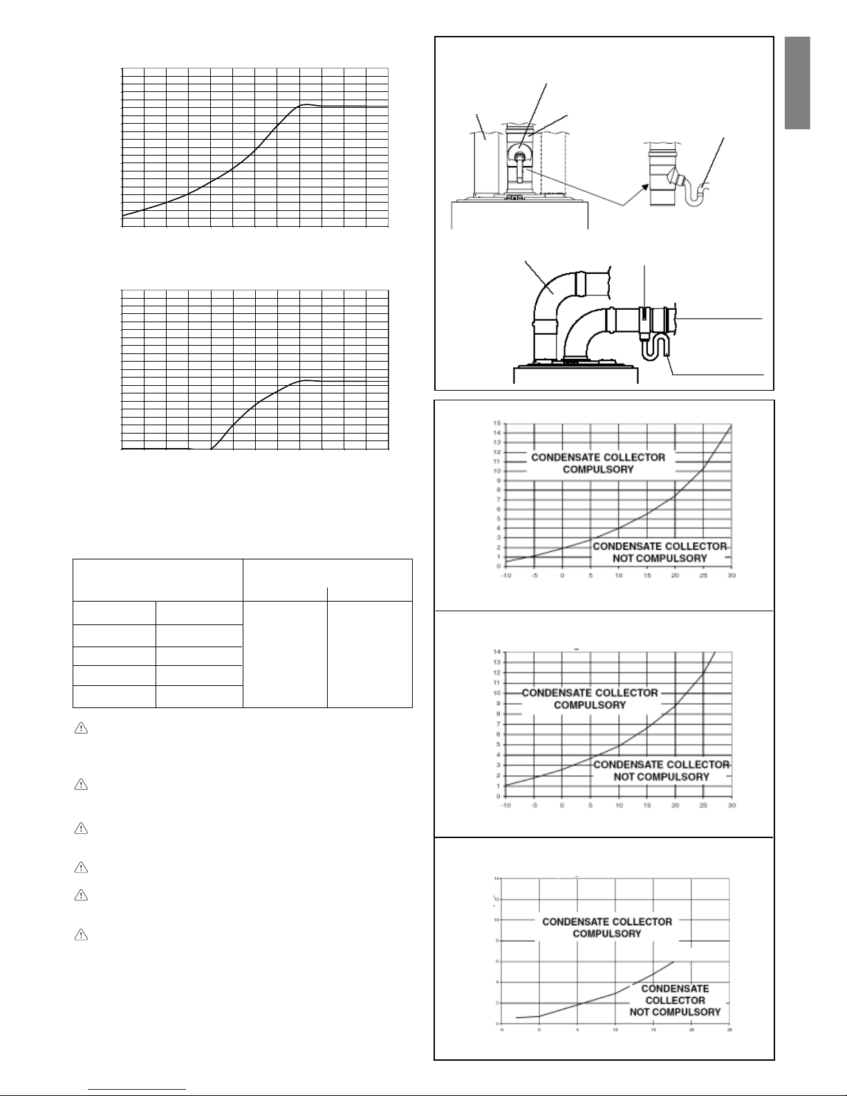
Concentric outlets (ø 60-100)
Concentric ducts may be placed in the most suitable direction for
installation requirements but special care must be taken as regards
the external temperature and the length of the duct.
Consult the graphs to find out whether a condensate collector is
required.
8.
FUMES EXHAUSTION AND BURNING
AIR SUCTION (MIX C.S.I.-MIX R.S.I.)
pressure drop
for each bend (m)
45° 90°
max. linear length
concentric duct ø 60-100 (m)
3,40
26 MIX C.S.I.
0,5 0,85
3,4030 MIX C.S.I.
3,4030 MIX R.S.I.
235 MIX C.S.I.
If the appliance works at temperatures lower than 50 °C (e.g.:
with external probe), the maximum permitted length must be
decreased by 1 metre.
The fumes outlet duct must slope by 1% towards the condensate collector.
The condensate collector can only be applied to the fumes
outlet, within 0.85 m from the boiler; connect the trap of the
condensate collector to a waste water drain.
Uninsulated fumes outlets are potential hazards.
The boiler automatically adapts ventilation according to the type
of installation and the length of the duct. Do not obstruct or narrow
the comburent air inlet duct in any way.
EXHAUSTION CONFIGURATIONS (fig. 7)
Boiler is homologated for the following exhaustion configurations:
C12 Concentric wall exhaustion. Pipes can separately start from
boiler, but outlets must be concentric or close enough to be
subject to similar wind conditions (within 50 cm)
C22 Concentric exhaustion in common chimney (suction and
exhaustion in the same chimney)
C32 Concentric roof exhaustion. Outlets like C12
C42 Exhaustion and suction in common separate chimneys, but
subject to similar wind conditions
C52 Wall or roof separate exhaustion and suction in different
pressure areas. Exhaustion and suction must never be located
on opposite walls
C62 Exhaustion and suction with separately certified and sold
pipes (1856/1)
C82 Single or common chimney exhaustion and wall suction
Maximum length concentric ducts ø 60-100 26 MIX C.S.I.
EXHAUSTION LENGHT (m)
EXTERNAL TEMPERATURE (°C)
Maximum length concentric ducts ø 60-100
30 MIX C.S.I. - 30 MIX R.S.I.
Maximum length concentric ducts ø 60-100
35 MIX C.S.I. - 35 MIX R.S.I.
EXHAUSTION LENGHT (m)EXHAUSTION LENGHT (m)
EXTERNAL TEMPERATURE (°C)
EXTERNAL TEMPERATURE (°C)
Fig. 9
Concentric outlets (ø 80-125)
The boiler is furnished predisposed for connection to concentric
discharge/aspiration ducts and with the air aspiration aperture closed.
The concentric pipes may be oriented in the direction best suited
to the requirements of the premises, respecting the maximum
lengths indicated in the table below.
For installation, follow the instructions provided with the kit.
Execute a Ø 140 mm hole for transit through the wall.
Particular care is required with the external temperature and the
length of the pipe. Refer to the graphics to establish whether the
condensation trap is mandatory or not. In the case of operation at
water temperatures below 60 °C, the use of a condensation trap is
mandatory. In the case of use of condensation trap the fumes
discharge pipe must be inclined by 1% towards the trap.
Connect the condensation trap siphon to a white water outlet pipe.
Non insulated discharge pipes are potential sources of danger.
CONCENTRIC OUTLETS (ø 60-100)
Fig. 8a
Concentric
outlet
Clamp
Condensate
collector
Condensate
drain trap
pressure drop
for each bend (m)
45° 90°
length of ducts
vertical and horizontal (m)
7,626 MIX C.S.I.
1,35 2,2
7,630 MIX C.S.I.
7,630 MIX R.S.I.
4,235 MIX C.S.I.
35 MIX R.S.I.
2
35 MIX R.S.I.
4,2
Page 7
7
English
Twin outlets (ø 80)
Twin ducts can be placed in the most suitable direction for
installation requirements but special care must be taken as regards
the temperature of the installation site and the length of the fumes
duct. To install, follow the instructions supplied with the kit.
In the event of installation with external discharge sections, to
calculate the maximum permitted length without a condensate
collector, refer to the external temperature instead of that of the
installation site of the boiler.
If the appliance works at temperatures lower than 50°C (e.g.:
installations with external probe), the maximum permitted
length without condensate collector must be decreased by
0.85 metres.
The condensate collector can only be applied to the fumes
outlet, within 0.85 m from the boiler; connect the trap of the
condensate collector to a waste water drain.
The fumes outlet duct must slope by 1% towards the condensate collector.
The boiler automatically adapts ventilation according to the
type of installation and the length of the ducts. Do not obstruct
or narrow the ducts in any way.
If the length of the ducts is different from that indicated in the
table to the side:
- for model 26 MIX C.S.I., the sum of the lengths of the inlet
and outlet ducts must be less than 30 metres, but the
length of a single duct must not exceed 18 metres
- for models 30 MIX C.S.I. - MIX R.S.I., the sum of the lengths
of the inlet and outlet ducts must be less than 28 metres,
but the length of a single duct must not exceed 17 metres
- for model 35 MIX C.S.I. - MIX R.S.I., the sum of the lengths
of the inlet and outlet ducts must be less than 12 metres,
but the length of a single duct must not exceed 8 metres.
max. length
twin duct (ø 80) (m)
15 + 1526 MIX C.S.I.
14 + 1430 MIX C.S.I.
14 + 1430 MIX R.S.I.
6 + 635 MIX C.S.I.
pressure drop
for each bend (m)
45°
90°
0,85
0,5
Maximum length twin ducts ø 80 26 MIX C.S.I.
EXHAUSTION LENGHT (m)
EXTERNAL TEMPERATURE (°C)
EXHAUSTION LENGHT (m)
EXTERNAL TEMPERATURE (°C)
Maximum length twin ducts ø 80
30 MIX C.S.I. - 30 MIX R.S.I.
EXHAUSTION LENGHT (m)
EXTERNAL TEMPERATURE (°C)
Maximum length twin ducts ø 80
35 MIX C.S.I. - 35 MIX R.S.I.
Fig. 10
0,0
0,5
1,0
1,5
2,0
2,5
3,0
3,5
4,0
4,5
5,0
5,5
6,0
6,5
7,0
7,5
8,0
8,5
9,0
9,5
10,0
-30 -25 -20 -15 -10 -5 0 5 10 15 20 2 5 30
0,0
0,5
1,0
1,5
2,0
2,5
3,0
3,5
4,0
4,5
5,0
5,5
6,0
6,5
7,0
7,5
8,0
8,5
9,0
9,5
10,0
-30-25-20-15-10-5 0 5 1015202530
EXHAUSTION LENGHT (m)
EXTERNAL TEMPERATURE (°C)
EXHAUSTION LENGHT (m)
EXTERNAL TEMPERATURE (°C)
26 - 30kW
35kW
TWIN OUTLETS (ø 80)
Condensate
collector
Condensate
collector
Condensate
drain trap
Condensate
drain trap
Air intake
duct
Air intake
duct
Fumes
outlet duct
Fumes
outlet duct
Fig. 8b
CONDENSATE COLLECTOR
COMPULSORY
CONDENSATE COLLECTOR
NOT COMPULSORY
CONDENSATE COLLECTOR
COMPULSORY
CONDENSATE COLLECTOR
NOT COMPULSORY
35 MIX R.S.I.
6 + 6
Page 8

8
99
99
9
..
..
.
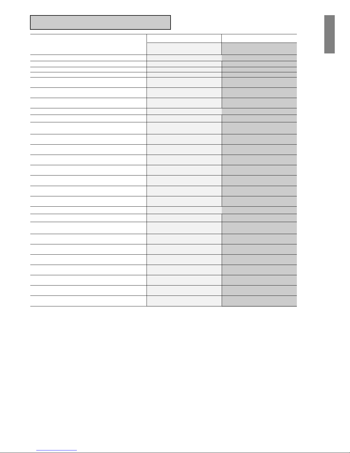
TECHNICAL DATA
CH/DHW* nominal heating capacity (Hi) kW 26,70 31,30 28,80 33,20 37,80
kcal/h 22.962 26.918 24.768 28.552 32.508
CH/DHW* nominal heating power kW 24,03 28,30 26,21 30,38 35,31
kcal/h 20.666 24.334 22.539 26.125 30.362
CH reduced heating capacity (Hi) kW 8,30 10,70 8,50 9,80 9,95
kcal/h 7.138 9.202 7.310 8.428 8.557
CH reduced heating power kW 7,05 9,21 7,70 8,86 9,18
kcal/h 6.060 7.923 6.623 7.619 7.898
DHW* reduced heating capacity (Hi) kW 8,30 8,70 8,50 9,80 9,95
kcal/h 7.138 7.482 7.310 8.428 8.557
DHW* reduced heating power kW 7,05 7,49 7,70 8,86 9,18
kcal/h 6.060 6.442 6.623 7.619 7.898
Working efficiency Pn max - Pn min % 90,0-84,9 90,4-86,1 91,0-90,6 91,5-90,4 93,4-92,3
Working efficiency 30% % 89,9 90,3 91,9 92,2 94,5
Electric power W 85 85 120 150 160
Supply voltage V - Hz 230-50 230-50 230-50 230-50 230-50
Protection level IP X5D X5D X5D X5D X5D
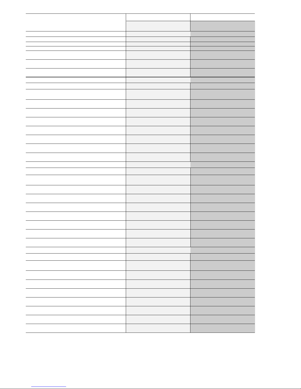
Chimney and skirt losses with burner off % 0,07-0,80 0,07-0,80 0,80-0,07 0,80-0,07 0,80-0,07
CH operation
Maximum pressure - temperature bar-°C 3-90 3-90 3-90 3-90 3-90
Minimum pressure for standard working/operating bar 0,25-0,45 0,25-0,45 0,25-0,45 0,25-0,45 0,25-0,45
Selection field of CH water temperature °C 40-80 40-80 40-80 40-80 40-80
Pump: maximum head available for system mbar 30 0 3 00 300 300 340
capacity l/h 1000 1000 1000 1000 1000
Membrane expansion tank l 8 8 8 8 10
Expansion vessel pre-charge (CH) bar 1 1 1 1 1
DHW operation*
Maximum pressure bar 6 6 6 6 6
Minimum pressure bar 0,1 5 0,15 0,1 5 0,15 0,15
Specific capacity following EN625 l/min - - 11,85 14 Hot water quantity: Δt 30° C l/min 11,5 13,5 - - 16,9
DHW minimum capacity l/min 2 2 2 2 2
Selection field of DHW temperature °C 35-60 35-60 35-60 35-60 35-60
Flow regulator l/min 1 0 1 2 1 1 13 15
Gas pressure
Category (extra EC countries) II2H3+ II2H3+ II2H3+ II2H3+ II2H3+
Natural gas pressure (G20) mbar 2 0 20 20 20 20
LPG pressure (G30/G31) mbar 28-30/37 28-30/37 28-30/37 28-30/37 28-30/37
Category (MT) I3B/P I3B/P I3B/P I3B/P I3B/P
LPG pressure (G30/G31) mbar 30 30 30 30 30
Hydraulic connections
CH input-output Ø 3/4” 3/4” 3/4” 3/4” 3/4”
DHW input-output (MIX C.S.I. - C.A.I.) Ø 1/2” 1/2” 1/2” 1/2” 1/2”
Water tank delivery-return (MIX R.S.I. - R.A.I.) Ø - 3/4” - 3/4” 3/4”
Gas input Ø 3/4” 3/4” 3/4” 3/4” 3/4”
Boiler dimensions and weight
Height mm 740 740 740 740 780
Width mm 400 450 400 450 500
Depth mm 332 332 332 332 332
Weight kg 30 33 (C.A.I.) 34 36 (MIX C.S.I.) 43 (MIX C.S.I.)
Weight kg - 32 (R.A.I.) - 35 (MIX R.S.I.) 41 (MIX R.S.I.)
Fan performance
Residual head with 0.85m concentric pipes mbar - - 0,2 0,2 0,2
Residual head of boiler without pipes mbar - - 0,35 0,35 1,15
Flow rates (G20)
Air capacity Nm3/h 46,914 54,996 48,34 54,107 60,724
Fumes capacity Nm3/h 49,591 58,135 51,23 57,44 64,515
Mass flow (max-min) gr/s 16,92-15,01 19,84-17,98 17,45-10,24 19,54-13,64 21,93-13,17
Fume exhaustion pipe
Diameter mm 130 140 - - -
Fume exhaustion and air suction concentric pipe
Diameter mm - - 60-100 60-100 60-100
Max lenght m - - 3,40 3,40 2,00
Loss for a 90°/45° bend m - - 0,85/0,5 0,85/0,5 0,85/0,5
Hole in wall (diameter) mm - - 105 105 105
Diameter mm - - 80-125 80-125 80-125
Max lenght m - - 7,6 7,6 4,2
Loss for a 90°/45° bend m - - 2,2/1,35 2,2/1,35 2,2/1,35
Hole in wall (diameter) mm - - 140 140 140
Fume exhaustion and air suction separated pipe
Diameter mm - - 80 80 80
Max lenght m - - 15+15 14+14 6+6
Loss for a 90°/45° bend m - - 0,8/0,5 0,8/0,5 0,8/0,5
NOx 3 class 2 class 2 class 3 class 3 class
Emission values at maximum and minimum of gas G20 **
Maximum CO s.a. lower than p.p.m. 100 130 100 90 90
CO
2
% 6,40 6,40 6,70 6,90 7,00
NOx s.a. lower than p.p.m. 160 210 190 140 120
Δt fumes °C 113 106 133 132 116
Minimum CO s.a. lower than p.p.m. 130 90 120 100 120
CO
2
% 2,23 2,40 3,35 2,90 3,05
NOx s.a. lower than p.p.m. 100 150 140 110 100
Δt fumes °C 71 70 63 7 2 62
* DHW values refer to MIX C.S.I. - C.A.I. models.
** C.A.I. - R.A.I.: tested with Ø 130 (24kW), Ø 140 (28kW) - lenght 0,5m.
** MIX C.S.I. - MIX R.S.I.: tested with Ø 60-100 concentric - lenght 0,85m - water temperature 80-60°C.
C.A.I.
24kW
C.A.I.
R.A.I.
28kW
MIX C.S.I.
26kW
MIX C.S.I.
MIX R.S.I.
30kW
MIX C.S.I.
MIX R.S.I.
35kW
Page 9
9
English
10.
MULTIGAS TABLE
Parameters Methane Liquid gas
(G20) Butane Propane
(G30) (G31)
C.A.I. - R.A.I.
Lower Wobbe index (15°C-1013 mbar) MJ/m3S 45,67 80,58 70,69
Lower heat value MJ/m3S 34,02 116,09 88
MJ/kgs - 45,65 46,34
Supply nominal pressure (Extra EC countries) mbar 20 28-30 37
(mm H2O) (203,9) (285,5-305,9) (377,3)
Supply nominal pressure (MT) mbar 30
(mm H2O) (305,9)
Supply minimum pressure mbar 13,5
(mm H2O) (137,7) -
24 kW C.A.I.
Main burner (12 nozzles) Ø mm 1,3 0,77 0,77
CH maximum gas capacity Sm3/h 2,82 - -
kg/h - 2,10 2,07
DHW maximum gas capacity Sm3/h 2,82 - -
kg/h - 2,10 2,07
CH minimum gas capacity Sm3/h 0,88 - -
kg/h - 0,65 0,64
DHW minimum gas capacity Sm3/h 0,88 - -
kg/h - 0,65 0,64
Maximum pressure downstrean CH valve mbar 11,80 28,00 36,00
mm H2O 120,33 285,52 367,10
Maximum pressure downstrean DHW valve mbar 11,80 28,00 36,00
mm H2O 120,33 285,52 367,10
Minimum pressure downstrean CH valve mbar 1,30 3,10 4,00
mm H2O 13,26 31,61 40,79
Minimum pressure downstrean DHW valve mbar 1,30 3,10 4,00
mm H2O 13,26 31,61 40,79
28 kW C.A.I. - R.A.I.
Main burner (14 nozzles) Ø mm 1,3 0,77 0,77
CH maximum gas capacity Sm3/h 3,31 - -
kg/h - 2,47 2,43
DHW maximum gas capacity* Sm3/h 3,31 - -
kg/h - 2,47 2,43
CH minimum gas capacity Sm3/h 1,13 - -
kg/h - 0,84 0,83
DHW minimum gas capacity* Sm3/h 0,92 - -
kg/h - 0,69 0,68
Maximum pressure downstrean CH valve mbar 11,90 28,00 35,80
mm H2O 121,35 285,52 365,06
Maximum pressure downstrean DHW valve* mbar 11,90 28,00 35,80
mm H2O 121,35 285,52 365,06
Minimum pressure downstrean CH valve mbar 1,50 3,80 5,30
mm H2O 15,30 38,75 54,05
Minimum pressure downstrean DHW valve* mbar 1,10 2,50 3,30
mm H2O 11,22 25,49 33,65
* DHW values refer to MIX C.S.I. - C.A.I. models.
Page 10
10
Parameters Methane Liquid gas
(G20) Butane Propane
(G30) (G31)
MIX C.S.I. - MIX R.S.I.
Lower Wobbe index (15°C-1013 mbar) MJ/m3S 45,67 80,58 70,69
Lower heat value MJ/m3S 34,02 116,09 88
MJ/kgs - 45,65 46,34
Supply nominal pressure (Extra EC countries) mbar 20 28-30 37
(mm H2O) (203,9) (285,5-305,9) (377,3)
Supply nominal pressure (MT) mbar 30
(mm H2O) (305,9)
Supply minimum pressure mbar 13,5
(mm H2O) (137,7) -
26 kW MIX C.S.I.
Main burner (13 nozzles) Ø mm 1,35 0,78 0,78
CH maximum gas capacity Sm3/h 3,05 - -
kg/h - 2,27 2,24
DHW maximum gas capacity Sm3/h 3,05 - -
kg/h - 2,27 2,24
CH minimum gas capacity Sm3/h 0,90 - -
kg/h - 0,67 0,66
DHW minimum gas capacity Sm3/h 0,90 - -
kg/h - 0,67 0,66
Maximum pressure downstrean CH valve mbar 10,60 27,90 35,50
mm H2O 108,09 284,50 362,00
Maximum pressure downstrean DHW valve mbar 10,60 27,90 35,50
mm H2O 108,09 284,50 362,00
Minimum pressure downstrean CH valve mbar 1,10 2,60 3,60
mm H2O 11,22 26,51 36,71
Minimum pressure downstrean DHW valve mbar 1,10 2,60 3,60
mm H2O 11,22 26,51 36,71
30 kW MIX C.S.I. - MIX R.S.I.
Main burner (15 nozzles) Ø mm 1,35 0,76 0,76
CH maximum gas capacity Sm3/h 3,51 - -
kg/h - 2,62 2,58
DHW maximum gas capacity* Sm3/h 3,51 - -
kg/h - 2,62 2,58
CH minimum gas capacity Sm3/h 1,04 - -
kg/h - 0,77 0,76
DHW minimum gas capacity* Sm3/h 1,04 - -
kg/h - 0,77 0,76
Maximum pressure downstrean CH valve mbar 10,10 27,50 35,40
mm H2O 102,99 280,42 360,98
Maximum pressure downstrean DHW valve* mbar 10,10 27,50 35,40
mm H2O 102,99 280,42 360,98
Minimum pressure downstrean CH valve mbar 1,00 2,80 3,60
mm H2O 10,20 28,55 36,71
Minimum pressure downstrean DHW valve* mbar 1,00 2,80 3,60
mm H2O 10,20 28,55 36,71
35 kW MIX C.S.I. - MIX R.S.I.
Main burner (16 nozzles) Ø mm 1,4 0,8 0,8
CH maximum gas capacity Sm3/h 4,00 - -
kg/h - 2,98 2,94
DHW maximum gas capacity Sm3/h 4,00 - -
kg/h - 2,98 2,94
CH minimum gas capacity Sm3/h 1,05 - -
kg/h - 0,78 0,77
DHW minimum gas capacity Sm3/h 1,05 - -
kg/h - 0,78 0,77
Maximum pressure downstrean CH valve mbar 9,60 27,30 35,40
mm H2O 97,89 278,38 360,98
Maximum pressure downstrean DHW valve mbar 9,60 27,30 35,40
mm H2O 97,89 278,38 360,98
Minimum pressure downstrean CH valve mbar 0,70 2,10 2,80
mm H2O 7,14 21,41 28,55
Minimum pressure downstrean DHW valve mbar 0,70 2,10 2,80
mm H2O 7,14 21,41 28,55
* DHW values refer to MIX C.S.I. - C.A.I. models.
Page 11

11
English
11.
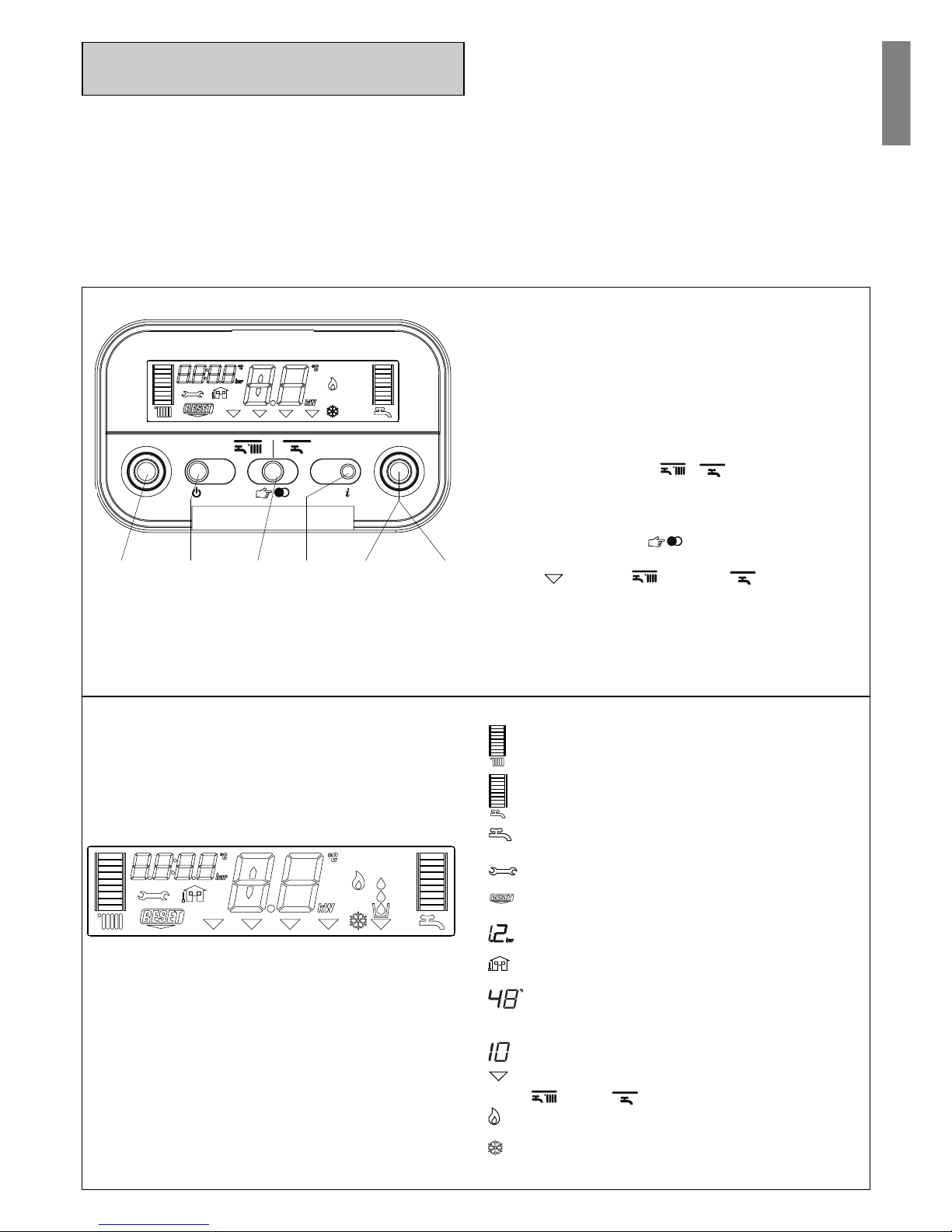
START-UP AND OPERATION
(C.A.I. - MIX C.S.I.)
Description of commands
Heating water temperature selector: sets the heating water
temperature.
Domestic hot water temperature selector: sets the domestic
hot water temperature.
Function key:
- ON the boiler is electrically powered and waiting for
operating requests (
- )
- OFF the boiler is electrically powered but will not respond
to operating requests
- RESETresets the boiler following a fault
Operating mode button: allows the most suitable operating
mode to be selected ( winter - winter comfort- summer
- summer comfort).
Info button: shows a sequence of information concerning the
operating status of the machine.
Filling button: pushing it, the boiler automatically fills the system
until the pressure reaches 1 to 1.5 bar.
The boiler produces heating and domestic hot water.
The control panel (fig. 13) contains the main boiler control and
management functions.
Fig. 13
Description of display symbols
graduated heating water temperature scale with heating
function symbol
graduated domestic hot water temperature scale with
domestic hot water function symbol
fault symbol (for details, please see page 15)
reset symbol (for details, please see page 15)
pressure value
external sensor connection
heating/domestic hot water temperature
or
fault symbol (e.g. 10 - no flame)
function selector (turned to the chosen operating mode:
winter - winter comfort- summer - summer
comfort)
burner operating symbol
anti-freeze function active symbol
system filling function symbol
fill symbol
Fig. 14
Domestic
hot water
temperature
selector
Operating
mode button
ON-OFF-RESET
function selector
Filling
button
Heating water
circuit temperature
selector
INFO
button
Page 12
12
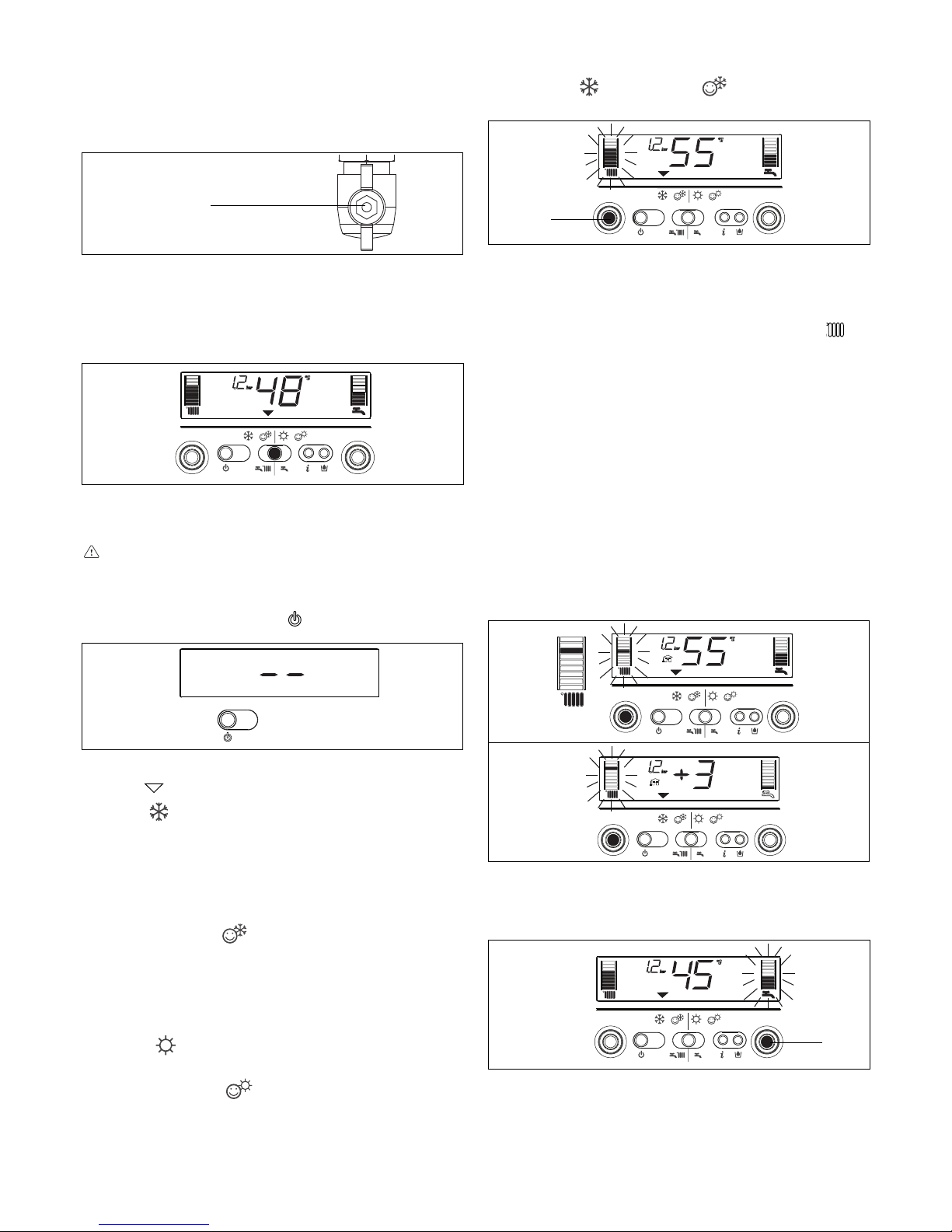
Adjusting heating water temperature
Turning the selector A (fig. 18), after having positioned the selector
mode on winter
or winter comfort , it is possible to regulate
the heating water temperature.
Turn clockwise to increase the temperature and anticlockwise to
decrease. The bar segments light up (every 5°C) as the temperature is increased. The selected temperature value appears on the
display. If you enter the S.A.R.A. adjustment field (from 55 to 65 °C)
while selecting the heating water temperature, the symbol
and
the graduated scale start flashing. For details about the S.A.R.A.
function, read page 14. The selected temperature value appears
on the display.
Adjusting heating water temperature with an external sensor
connected
When an external probe is connected, the value of the delivery
temperature is automatically chosen by the system which rapidly
adjusts ambient temperature to the changes in external temperature. Just the central segment of the bar is illuminated (fig. 19).
To increase or decrease the temperature with respect to the value
automatically calculated by the electronic board, turn the heating
water selector clockwise to increase and anticlockwise to decrease.
The bar segments light up (at every comfort level), correction
tolerance lies between - 5 and + 5 comfort levels (fig. 19). When
choosing the level of comfort, the digit area of the display shows
the required level of comfort while the bar shows the matching
segment (fig. 20).
Adjusting domestic hot water temperature
To adjust domestic hot water temperature, turn switch B (fig. 21)
clockwise to increase and anticlockwise to decrease. The bar
segments light up (every 3°C) as the temperature is increased.
The selected temperature value appears on the display.
When choosing the temperature, both for heating and domestic
hot water, the display shows the value being selected. About 4
seconds after the selection has been made, the modification is
memorised and the display returns to the delivery temperature
read by the probe.
Switching on
Switch on the boiler as follows:
- access the gas tap through the slots in the cover located in the
lower part of the boiler
- open the gas tap by turning it anti-clockwise (fig. 15)
- power the boiler.
When powered, the boiler performs a test sequence and a series
of numbers and letters are shown on the display.
If the test is successful the boiler is ready to work about 4 seconds
after the cycle ends.
The display will look like fig. 16.
If the test is unsuccessful, the boiler will not work and a “0” will
flash on the display.
In this case, contact the Technical Assistance Centre.
The boiler turns on in the status it was in before it was switched
off: if the boiler was in the winter comfort mode when it was
switched off, it will turn on again in the winter comfort mode. If it
was in the OFF mode, the display will show two segments in the
central area (fig. 17). Press the
button to enable operation.
- press the function selector until the indicator moves to the required
function
, depending on the kind of operation chosen.
- WINTER
: with the selector in this position, the heating water
and domestic hot water functions are activated.
In this position the S.A.R.A. function is enabled in the heating
mode (see chapter “Boiler functions”). The boiler actives the
temperature stabiliser in order to ensure the continuous
production of domestic hot water, even for small demands or
when the inlet water is already hot. This prevents temperature
oscillations due to the burner switching off/on.
- WINTER COMFORT
: with the selector in this position, as
well as the traditional function of heating water and domestic
hot water, the preheating function is also activated which keeps
the water in the domestic hot water exchanger hot in order to
reduce waiting times. The S.A.R.A. Booster and Domestic hot
water preheating functions are enabled in this position (see
chapter “Boiler functions”).
- SUMMER
: with the selector in this position, just the traditional
domestic hot water function is activated.
- SUMMER COMFORT
: with the selector in this position, the
boiler provides just domestic hot water with a temperature
stabiliser for small deliveries. Ideal at the times of year or in the
areas where the mains water is already warm. In these conditions,
the temperature of the hot water produced by a boiler with just
traditional functions (see SUMMER and WINTER COMFORT)
may be instable.
Fig. 15
open
position
Fig. 16
Fig. 17
Fig. 18
Fig. 21
A
Fig. 19
°C
+ 4/5
+ 3
+ 2
+ 1
0
- 1
- 2
- 3
- 4/5
Fig. 20
B
Page 13
13
English
If this condition occurs it means that the system is incorrectly
pressurised though the boiler will continue to work regularly.
Press the circuit filling button
to start-up the filling sequence.
Press the circuit filling button
a second time to interrupt the
filling sequence. During filling, the drops of the circuit filling
symbol
and the growing pressure value appear on the
display in a cascade sequence (fig. 27).
After filling, the
symbol is displayed for a few moments and then
turns off.
Note
During filling, the boiler does not perform other functions. For
example, if there is a request for domestic hot water, the boiler is
unable to provide it until filling has finished.
Note
If circuit pressure reaches 0.6 bar, the pressure value flashes on
the display (fig. 28b); if it falls below a minimum safety value (0.3
bar), fault code 41 appears on the display (fig. 28a) for a certain
time, following which, if the fault persists, fault code 40 is displayed
(see chapter on “Troubleshooting”).
In the event of fault 40, press
to reset and then to start filling
the circuit. If you have to fill the system several times, contact the
Technical Service Centre to check whether the heating circuit is
watertight (see if there are any leaks).
Information
Press
, the display turns off and just the word InFO appears (fig.
29). Press the button
to view operating information. Press the
button again to move on to the next piece of information. If the
button is not pressed, the system automatically exits the function.
Info list:
Info 0 shows the word InFO (fig. 29)
Info 1 only with the external probe connected, displays external
temperature (e.g. 12 °C) (fig. 30).
The values shown on the display range between - 40 °C
and 40 °C.
Beyond these values the display shows “- -”
Fig. 27
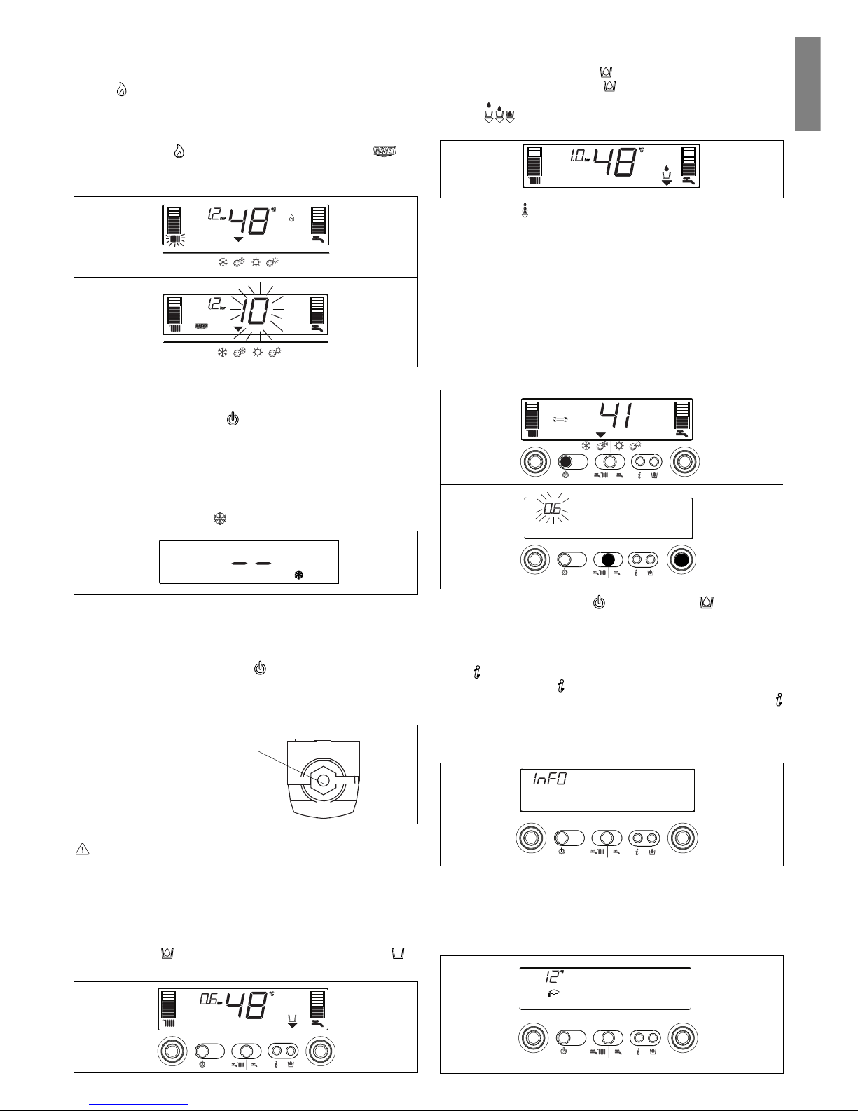
Working the boiler
Adjust the ambient thermostat to the required temperature (approx.
20 °C). If there is a demand for heating water, the boiler starts
and the
symbol is shown on the display (fig. 22). The boiler will
remain working until the set temperatures are reached, after which
it will go on stand-by. In the event of ignition or operating faults,
the boiler will perform a “safety stop”.
The flame symbol
will go out and the fault code and will
be displayed (fig. 23). For a description of faults and how to reset
them, consult chapter “Troubleshooting”.
Switching off
Switching off for short periods
For brief absences press the
button to switch off the boiler. The
display will show two segments in the central area (fig. 17). When
the boiler remains powered with the gas tap open, it is protected
by the following systems:
- anti-freeze (fig. 24): when the temperature of the water in the
boiler falls below safety values, the circulator and the burner
work at minimum power to increase the water temperature to a
safe value (35 °C). The
symbol lights up on the display.
- circulator anti-block: one operating cycle is performed every
24 hours.
Switching off for long periods
For prolonged absences press the
button to switch off the boiler
(fig. 17). The display will show two segments in the central area.
Turn the main switch to “off”.
Turn off the gas tap under the boiler by turning it clockwise (fig. 25).
In this case, the anti-freeze and anti-block systems are disabled.
Empty the water circuit or suitably protect it with a good make
of anti-freeze. Drain the domestic hot water circuit.
Fig. 23
Fig. 22
Fig. 24
Fig. 25
tap
closed
Boiler functions
Semi-automatic filling
The boiler features a semi-automatic filling device which turns on
by pressing the button when the corresponding symbol is
shown on the display (fig. 26).
Fig. 26
Fig. 29
Fig. 28a
Fig. 28b
Fig. 30
Page 14
14
Fig. 34
Fig. 35
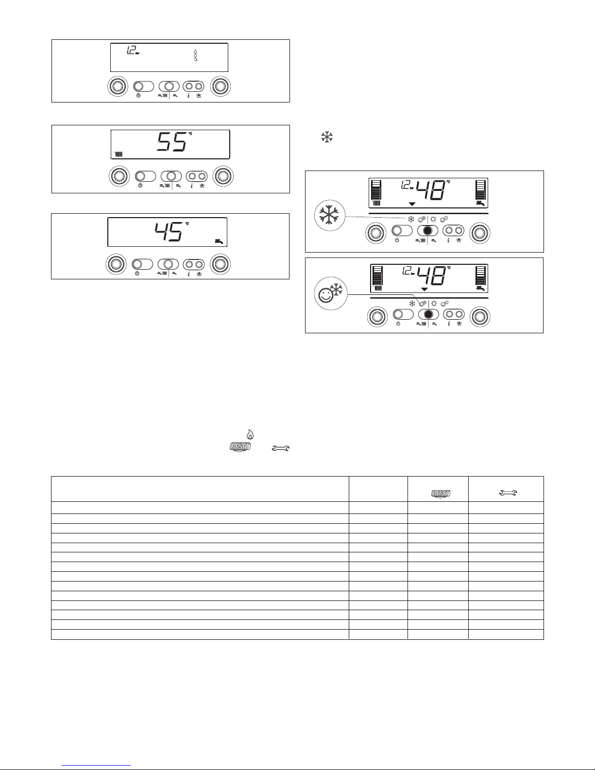
Info 2 shows circuit pressure (fig. 31)
Info 3 shows the set heating temperature (fig. 32)
Info 4 shows the set domestic hot water temperature (fig. 33).
S.A.R.A. function
If the “winter” mode is selected, the S.A.R.A. (Automatic Ambient
Adjustment System) function can be activated.
Turn the heating water temperature selector to a temperature
ranging between 55 and 65 °C.
The S.A.R.A. self-adjustment system activates: depending on the
temperature set on the ambient thermostat and the time taken to
reach it, the boiler automatically adjusts the heating water temperature to reduce operating times, thereby increasing operating
comfort and energy saving.
Fig. 31
Fig. 32
Fig. 33
S.A.R.A. BOOSTER function
If the “winter comfort” mode is selected, the S.A.R.A. Booster
function is activated for the heating circuit and reaches the required
ambient temperature more quickly.
DOMESTIC HOT WATER PRE-HEATING function
If the “winter comfort” mode is selected, the domestic hot water
Preheating function is enabled. This function sets out to keep the
domestic hot water contained in the boiler hot, thereby considerably
reducing delivery waiting times.
The
function should be selected to reduce power consumption
in areas where the mains water is not particularly cold.
In this case, the Booster and Preheating functions are not activated.
Troubleshooting
When a fault appears on the display, the flame symbol goes out,
a flashing code is shown and the two symbols
and
appear either together or separately.
For a description of the faults, consult the following table
.
(D) Permanent
(T) Temporary. In this operating status the boiler attempts to eliminate the fault on its own
(°) See NOTE in the next page.
(*) For the “insufficient circuit pressure” fault, proceed with the circuit filling operations described in the “Boiler functions” chapter.
FAULT Alarm Symbol Symbol
ID
FLAME FAILURE BLOCK (D) 10 YES NO
LIMIT THERMOSTAT (D) 20 YES NO
BURNER THERMOSTAT (D) (MIX C.S.I) 21 YES NO
FUMES THERMOSTAT (D) (C.A.I.) 22 YES YES
FUMES OUTLET OR AIR PRESSOSTAT (D) (MIX C.S.I.) 30 YES NO
FUMES OUTLET OR AIR PRESSOSTAT (T) (MIX C.S.I.) 31 NO YES
INSUFFICIENT SYSTEM PRESSURE (D*) 40 YES NO
INSUFFICIENT SYSTEM PRESSURE (T*) 41 NO YES
WATER PRESSURE TRANSDUCER (D) 42 YES YES
FALSE FLAME (D) 50 YES YES
ELECTRONIC BOARD (D) 51-59 YES YES
SANITARY PROBE 1 (T°) 60 NO YES
PRIMARY PROBE (T) 71 NO YES
LOW TEMPERATURE THERMOSTAT (T) 77 YES YES
Page 15

15
English
Resetting faults
Wait for about 10 seconds before resetting operating conditions.
Then proceed as follows:
1) Viewing just the
symbol
If
disappears, it means that an operating fault has been
discovered which the boiler is attempting to solve on its own
(temporary stoppage). If the boiler does not resume normal
operation, two things may happen:
case A (fig. 36)
disappears, the symbol and a different alarm code
appear. In this case, proceed as described in point 2.
case B (fig. 37)
and a different alarm code are displayed together with .
In this case, proceed as described in point 3.
2) Viewing just the
symbol (fig. 38)
Press the
button to reset the appliance. If the boiler starts the
ignition phase and resumes normal operation, it may have
stopped by accident.
If these stoppages should continue, contact the Technical
Assistance Centre.
3) Viewing the
and symbols (fig. 39)
Contact the Technical Assistance Centre.
Note
Fault in domestic hot water circuit sensor - 60: the boiler works
regularly but does not ensure the stability of the hot water temperature which, however, is delivered at a temperature of
approximately 50°C. The fault code is only displayed in standby.
12.
PROGRAMMING PARAMETERS
This boiler incorporates a new generation of electronic boards that, by
setting/modifying operating parameters, allow the boiler to be
personalised to satisfy various system and/or user requirements. The
programmable parameters are shown in the table on the next page.
The parameters must be programmed with the boiler in the
OFF position. To do this, press the
button until the display
shows “- -” (fig. 40).
During parameter modification operations, the “select
functions” button acts as an ENTER (confirm) button, the
button acts as an ESCAPE (escape) button. If no confirmation
is given within 10 seconds, the value is discarded and returns
to the previously set one.
Setting the password
Press and hold down the select functions button and the
button
together for about 10 seconds. The display will look like fig. 41.
Enter the password for accessing the parameter modifications
function by turning the domestic hot water temperature selector to
obtain the required value. The password for accessing the
parameter programming function is located on the back side of
the control panel. Confirm by pressing ENTER.
Modifying parameters
Turn the domestic hot water temperature selector (fig. 42) to
sequentially scroll the two-figure codes of the parameters indicated
in the table. After identifying the parameter you wish to modify,
proceed as follows:
- press ENTER to access the parameter modification function. When
ENTER is pressed, the previously set value starts flashing (fig. 43)
- turn the domestic hot water temperature selector to change the value
- press ENTER to confirm the new value. The digits stop flashing
(fig. 44)
- press ESCAPE to exit.
The boiler returns to the “- -” (OFF) status.
To reset, press the
button (fig. 40).
Fig. 36
Fig. 37
Fig. 38
“temporary
fault”
Fig. 39
Fig. 40
Fig. 41
Fig. 42
Fig. 43
Fig. 44
“temporary
fault”
“permanent
fault”
“permanent
fault”
ENTER
ESCAPE
parameter
value
parameter
number
Page 16

16
CC
CC
C
.A.A
.A.A
.A
.I.I
.I.I
.I
.:.:
.:.:
.:
pr pr
pr pr
pr
ogog
ogog
og
rr
rr
r
aa
aa
a
mmabmmab
mmabmmab
mmab
le parle par
le parle par
le par
aa
aa
a
metersmeters
metersmeters
meters
N° DESCRIPTION PARAMETERS UNIT OF MIN MAX DEFAULT PARAMETERS
PAR. MEASURE (setted in factory) (setted by techn. assist. centre)
1 GAS TYPE 1 Methane 1-2
2 LPG
3 Methane France
3 INSULATION LEVEL OF BUILDING (+) (*) min 5 20 5
10 DHW MODE 0 (OFF) 1
1 (Instantaneous)
2 (Mini-tank)
3 (External water-tank with thermostat)
4 (External water-tank with sensor)
11 DHW CIRCUIT MAXIMUM SET-POINT ° C 40 60 60
12 THIS PARAMETER IS NOT USED ON THIS MODEL. DO NOT MODIFY 60
13 THIS PARAMETER IS NOT USED ON THIS MODEL. DO NOT MODIFY 80
14 THIS PARAMETER IS NOT USED ON THIS MODEL. DO NOT MODIFY 5
20 CH MODE 0 (OFF) 1
1 (ON)
2 (zone valves + remote control panel)
21 HEATING CIRCUIT MAXIMUM SET-POINT ° C 40 80 80
22 THIS PARAMETER IS NOT USED ON THIS MODEL. DO NOT MODIFY 40
28 MAX HEATING POWER REDUCTION TIMER min 0 20 15
29 FORCED HEATING SHUT DOWN TIMER min 0 20 3
30 HEATING TIMER RESET FUNCTION - 0 1 0
40 DHW THERMOSTAT OPERATING MODE 0 (OFF) 1
1 (AUTO)
2 (ON)
41 DHW PREHEATING FUNCTION 0 (OFF) 1
1 (AUTO)
2 (ON)
42 S.A.R.A. FUNCTION 0 (OFF) 1
1 (AUTO)
43 S.A.R.A. BOOSTER FUNCTION 0 (OFF) 1
1 (AUTO)
44 THERMOREGULATION FUNCTION 0 (OFF) 1
1 (AUTO)
45 INCLINATION THERMOREGULATION CURVE (OTC) (*) - 2,5 40 20
48 THIS PARAMETER IS NOT USED ON THIS MODEL. DO NOT MODIFY 0
50 THIS PARAMETER IS NOT USED ON THIS MODEL. DO NOT MODIFY 1
61 DHW ANTIFREEZE FUNCTION TEMPERATURE (ON) °C 0 10 4
62 HEATING ANTIFREEZE FUNC. DELIVERY TEMP. (ON) °C 0 10 6
85 SEMI-AUTOMATIC FILLING 0 (disabled)/1 (enabled) 1
86 AUTOMATIC FILLING PRESSURE (ON) bar 0.4 0.8 0.6
MIX CMIX C
MIX CMIX C
MIX C
.S.S
.S.S
.S
.I.I
.I.I
.I
.:.:
.:.:
.:
pr pr
pr pr
pr
ogog
ogog
og
rr
rr
r
aa
aa
a
mmabmmab
mmabmmab
mmab
le parle par
le parle par
le par
aa
aa
a
metersmeters
metersmeters
meters
N° DESCRIPTION PARAMETERS UNIT OF MIN MAX DEFAULT PARAMETERS
PAR. MEASURE (setted in factory) (setted by techn. assist. centre)
1 GAS TYPE 1 Methane 1-2
2 LPG
3 Methane France
2 BOILER POWER 26 (26kW) 26-30-34
30 (30kW)
34 (35kW)
3 INSULATION LEVEL OF BUILDING (+) (*) min 5 20 5
10 DHW MODE 0 (OFF) 1
1 (Instantaneous)
2 (Mini-tank)
3 (External water-tank with thermostat)
4 (External water-tank with sensor)
11 DHW CIRCUIT MAXIMUM SET-POINT ° C 40 60 60
12 THIS PARAMETER IS NOT USED ON THIS MODEL. DO NOT MODIFY 60
13 THIS PARAMETER IS NOT USED ON THIS MODEL. DO NOT MODIFY 80
14 THIS PARAMETER IS NOT USED ON THIS MODEL. DO NOT MODIFY 5
20 CH MODE 0 (OFF) 1
1 (ON)
2 (zone valves + remote control panel)
21 HEATING CIRCUIT MAXIMUM SET-POINT ° C 40 80 80
22 THIS PARAMETER IS NOT USED ON THIS MODEL. DO NOT MODIFY 40
28 MAX HEATING POWER REDUCTION TIMER min 0 20 15
29 FORCED HEATING SHUT DOWN TIMER min 0 20 3
30 HEATING TIMER RESET FUNCTION - 0 1 0
40 DHW THERMOSTAT OPERATING MODE 0 (OFF) 1
1 (AUTO)
2 (ON)
41 DHW PREHEATING FUNCTION 0 (OFF) 1
1 (AUTO)
2 (ON)
42 S.A.R.A. FUNCTION 0 (OFF) 1
1 (AUTO)
43 S.A.R.A. BOOSTER FUNCTION 0 (OFF) 1
1 (AUTO)
44 THERMOREGULATION FUNCTION 0 (OFF) 1
1 (AUTO)
45 INCLINATION THERMOREGULATION CURVE (OTC) (*) - 2,5 40 20
48 THIS PARAMETER IS NOT USED ON THIS MODEL. DO NOT MODIFY 0
50 THIS PARAMETER IS NOT USED ON THIS MODEL. DO NOT MODIFY 1
61 DHW ANTIFREEZE FUNCTION TEMPERATURE (ON) °C 0 10 4
62 HEATING ANTIFREEZE FUNC. DELIVERY TEMP. (ON) °C 0 10 6
85 SEMI-AUTOMATIC FILLING 0 (disabled)/1 (enabled) 1
86 AUTOMATIC FILLING PRESSURE (ON) bar 0.4 0.8 0.6
(*) parameters shown only with external sensor connected and parameter 44 in 1 (AUTO).
(+) for well-insulated buildings select values close to 20, for badly insulated buildings choose values close to 5.
T m. = maximum rated temperature of heating water
T e. = minimum rated external temperature
OTC = 10 x
Tm. - 20
20 - Te.
Parameter 45 “Inclination of thermoregulation curve (OTC)”
The curve must be chosen according to the geographical area and the type
of installation.
Page 17
17
English
Description of commands
Heating water temperature selector: sets the heating water
temperature.
Domestic hot water temperature selector (C case only): sets
the domestic hot water temperature storaged in the water tank.
Setting parameters selector (cases A, B and C): using in
calibration and programmation phase.
Function key:
- ON the boiler is electrically powered and waiting for
operating requests (
- )
- OFF the boiler is electrically powered but will not respond
to operating requests
- RESETresets the boiler following a fault
Operating mode button:
button allows to choose the
desired operating mode: pressing it, the indicator “function
selector”
moves to: (winter) or (summer, only if
water-tank connected).
Info button: shows a sequence of information concerning the
operating status of the machine.
Fig. 45
Description of display symbols
graduated heating water temperature scale with heating
function symbol
graduated domestic hot water temperature scale (shown
in C case only)
domestic hot water function symbol (shown in B and C
cases)
fault symbol (for details, please see page 21)
reset symbol (for details, please see page 21)
pressure value
external sensor connection
heating/domestic hot water temperature (shown in C case
only)
or
fault symbol (e.g. 10 - no flame)
function selector (turned to the chosen operating mode:
winter or summer (only if water-tank connected)
burner operating symbol
anti-freeze function active symbol
Fig. 46
13.
START-UP AND OPERATION
(R.A.I. - MIX R.S.I.)
This boiler is able to operate in different conditions:
CASE A) only heating
CASE B) only heating with external water tank connected,
managed by a thermostat, to prepare domestic hot
water
CASE C) only heating with external water tank connected,
managed by a temperature sensor (kit available
upon request), to prepare domestic hot water.
Depending on the type of installation selected, it is necessary
to set the parameter “domestic hot water mode”. This operation
must be performed by a Technical Service Centre when
starting-up the boiler.
Domestic hot water
temperature selector
(C case only)
Operating
mode button
ON-OFF-RESET
function selector
INFO
button
Heating water
circuit temperature
selector
Setting
parameters
selector
Page 18

18
Adjusting heating water temperature
Turning the selector A (fig. 52), after having positioned the selector
mode on winter , it is possible to regulate the heating water
temperature.
Turn clockwise to increase the temperature and anticlockwise to
decrease. The bar segments light up (every 5°C) as the temperature is increased. The selected temperature value appears on the
display.
Adjusting heating water temperature with an external sensor
connected
When an external probe is connected, the value of the delivery
temperature is automatically chosen by the system which rapidly
adjusts ambient temperature to the changes in external temperature. Just the central segment of the bar is illuminated (fig. 53).
To increase or decrease the temperature with respect to the value
automatically calculated by the electronic board, turn the heating
water selector clockwise to increase and anticlockwise to decrease.
The bar segments light up (at every comfort level), correction
tolerance lies between - 5 and + 5 comfort levels (fig. 53). When
choosing the level of comfort, the digit area of the display shows
the required level of comfort while the bar shows the matching
segment (fig. 54).
Switching on
Switch on the boiler as follows:
- access the gas tap through the slots in the cover located in the
lower part of the boiler
- open the gas tap by turning it anti-clockwise (fig. 47)
- power the boiler.
When powered, the boiler performs a test sequence and a series
of numbers and letters are shown on the display.
If the test is successful the boiler is ready to work about 4 seconds
after the cycle ends.
The display will look like fig. 48.
If the test is unsuccessful, the boiler will not work and a “0” will
flash on the display.
In this case, contact the Technical Assistance Centre.
The boiler turns on in the status it was in before it was switched
off: if the boiler was in the winter mode when it was switched off,
it will turn on again in the winter mode. If it was in the OFF mode,
the display will show two segments in the central area (fig. 49).
Press the
button to enable operation.
Choose the desired operating mode by pressing button,
until the
symbol moves to:
WINTER
SUMMER
WINTER function (fig. 50)
With the selector in this position, the boiler provides hot water for
the heating and, if an external water tank is connected, provides
water to the water tank to allow domestic hot water preparation.
Function S.A.R.A Booster is enabled in this position (see chapter
“Boiler functions”).
SUMMER function (only with external water tank connected,
fig. 51)
With the selector in this position, the boiler provides water to the
water tank with a temperature stabiliser to allow domestic hot water
preparation.
Fig. 47
Fig. 48
Fig. 49
Fig. 52
A
Fig. 53
Fig. 54
open
position
Fig. 50
Fig. 51
°C
+ 4/5
+ 3
+ 2
+ 1
0
- 1
- 2
- 3
- 4/5
Adjusting domestic hot water temperature
CASE A only heating - adjusting not applicable
CASE B only heating + water tank with thermostat: in this
condition every time there is a request from the water
tank thermostat, the boiler supplies hot water to
preparing domestic hot water. During this operation on
the display the icon
flashed.
CASE C only heating + water tank with sensor: to adjust domestic
hot water temperature storaged in the water tank, turn
switch D (fig. 55): clocwise to increase and
anticlockwise to decrease. The bar segments light up
(every 3°C) as the temperature is increased. About 4
seconds after the selection has been made, the
modification is memorised and the display returns to
the delivery temperature read by the sensor.
Page 19

19
English
Fig. 55
D
Working the boiler
Adjust the ambient thermostat to the required temperature (approx.
20 °C). If there is a demand for heating water, the boiler starts
and the
symbol is shown on the display (fig. 56). The boiler will
remain working until the set temperatures are reached, after which
it will go on stand-by. In the event of ignition or operating faults,
the boiler will perform a “safety stop”.
The flame symbol
will go out and the fault code and will
be displayed (fig. 57). For a description of faults and how to reset
them, consult chapter “Troubleshooting”.
Switching off
Switching off for short periods
For brief absences press the
button to switch off the boiler. The
display will show two segments in the central area (fig. 49). When
the boiler remains powered with the gas tap open, it is protected
by the following systems:
- anti-freeze (fig. 58): when the temperature of the water in the
boiler falls below safety values, the circulator and the burner
work at minimum power to increase the water temperature to a
safe value (35 °C). The
symbol lights up on the display.
- circulator anti-block: one operating cycle is performed every
24 hours.
Switching off for long periods
For prolonged absences press the button to switch off the boiler
(fig. 49). The display will show two segments in the central area.
Turn the main switch to “off”.
Turn off the gas tap under the boiler by turning it clockwise (fig. 59).
In this case, the anti-freeze and anti-block systems are disabled.
Empty the water circuit or suitably protect it with a good make
of anti-freeze.
Fig. 56
Fig. 57
Fig. 58
Fig. 59
tap
closed
Boiler functions
Filling the circuit
If circuit pressure reaches 0.6 bar, the pressure value flashes on
the display (fig. 60a); if it falls below a minimum safety value (0.3
bar), fault code 41 appears on the display (fig. 60b) for a certain
time, following which, if the fault persists, fault code 40 is displayed
(see chapter on “Troubleshooting”).
In the event of faul 40 (fig. 61) proceed as follow to restore the
correct pressure value:
- press
button
- open the filling tap external to the boiler, until the pressure shown
in the display is between 1 and 1,5 bar.
If you have to fill the system several times, contact the Technical
Service Centre to check whether the heating circuit is watertight
(see if there are any leaks).
Information
Press , the display turns off and just the word InFO appears (fig.
62). Press the button
to view operating information. Press the
button again to move on to the next piece of information. If the
button is not pressed, the system automatically exits the function.
Info list:
Info 0 shows the word InFO (fig. 62)
Info 1 only with the external probe connected, displays external
temperature (e.g. 12 °C) (fig. 63).
The values shown on the display range between - 40 °C
and 40 °C.
Beyond these values the display shows “- -”
Fig. 60a
Fig. 60b
Fig. 61
Fig. 62
Fig. 63
Page 20

20
Info 2 shows circuit pressure (fig. 64)
Info 3 shows the set heating temperature (fig. 65)
Info 4 shows the setted temperature (only water tank with sensor,
fig. 66).
Fig. 64
Fig. 65
Fig. 66
S.A.R.A. BOOSTER function
If the “winter” mode is selected, the S.A.R.A. Booster function is
activated for the heating circuit. This function allows to reach the
required ambient temperature more quickly.
Depending on the temperature set on the ambient thermostat and
the time taken to reach it, the boiler automatically adjusts the
heating water temperature to reduce operating times, thereby
increasing operating comfort and energy saving.
Fig. 67
Troubleshooting
When a fault appears on the display, the flame symbol goes out,
a flashing code is shown and the two symbols and
appear either together or separately.
For a description of the faults, consult the following table.
(D) Permanent
(T) Temporary. In this operating status the boiler attempts to eliminate the fault on its own
(°) Only with external water tank with sensor. The fault code is shown when the boiler is in stand-by
(*) For the “insufficient circuit pressure” fault, proceed with the circuit filling operations described in the “Boiler functions” chapter.
FAULT Alarm Symbol Symbol
ID
FLAME FAILURE BLOCK (D) 10 YES NO
LIMIT THERMOSTAT (D) 20 YES NO
BURNER THERMOSTAT (D) (MIX R.S.I.) 21 YES NO
FUMES THERMOSTAT (D) (R.A.I.) 22 YES YES
FUMES OUTLET OR AIR PRESSOSTAT (D) (MIX R.S.I.) 30 YES NO
FUMES OUTLET OR AIR PRESSOSTAT (T) (MIX R.S.I.) 31 NO YES
INSUFFICIENT SYSTEM PRESSURE (D*) 40 YES NO
INSUFFICIENT SYSTEM PRESSURE (T*) 41 NO YES
WATER PRESSURE TRANSDUCER (D) 42 YES YES
FALSE FLAME (D) 50 YES YES
ELECTRONIC BOARD (D) 51-59 YES YES
SANITARY PROBE 1 (T°) 60 NO YES
PRIMARY PROBE (T) 71 NO YES
LOW TEMPERATURE THERMOSTAT (T) 77 YES YES
Page 21

21
English
Resetting faults
Wait for about 10 seconds before resetting operating conditions.
Then proceed as follows:
1) Viewing just the
symbol
If
disappears, it means that an operating fault has been
discovered which the boiler is attempting to solve on its own
(temporary stoppage). If the boiler does not resume normal
operation, two things may happen:
case A (fig. 68)
disappears, the symbol and a different alarm code
appear. In this case, proceed as described in point 2.
case B (fig. 69)
and a different alarm code are displayed together with .
In this case, proceed as described in point 3.
2) Viewing just the
symbol (fig. 70)
Press the button to reset the appliance. If the boiler starts the
ignition phase and resumes normal operation, it may have
stopped by accident.
If these stoppages should continue, contact the Technical
Assistance Centre.
3) Viewing the
and symbols (fig. 71)
Contact the Technical Assistance Centre.
Fig. 68
Fig. 69
“temporary
fault”
“temporary
fault”
“permanent
fault”
“permanent
fault”
Fig. 70
Fig. 71
14.
PROGRAMMING PARAMETERS
This boiler incorporates a new generation of electronic boards that, by
setting/modifying operating parameters, allow the boiler to be
personalised to satisfy various system and/or user requirements. The
programmable parameters are shown in the table on the next page.
The parameters must be programmed with the boiler in the
OFF position. To do this, press the
button until the display
shows “- -” (fig. 72).
During parameter modification operations, the “select
functions” button acts as an ENTER (confirm) button, the
button acts as an ESCAPE (escape) button. If no confirmation
is given within 10 seconds, the value is discarded and returns
to the previously set one.
Setting the password
Press and hold down the select functions button and the
button
together for about 10 seconds. The display will look like fig. 73.
Enter the password for accessing the parameter modifications
function by turning the domestic hot water temperature selector to
obtain the required value. The password for accessing the
parameter programming function is located on the back side of
the control panel. Confirm by pressing ENTER.
Modifying parameters
Turn the domestic hot water temperature selector (fig. 74) to
sequentially scroll the two-figure codes of the parameters indicated
in the table. After identifying the parameter you wish to modify,
proceed as follows:
- press ENTER to access the parameter modification function. When
ENTER is pressed, the previously set value starts flashing (fig.75)
- turn the domestic hot water temperature selector to change the value
- press ENTER to confirm the new value. The digits stop flashing
- press ESCAPE to exit.
The boiler returns to the “- -” (OFF) status.
To reset, press the
button (fig. 72).
Fig. 72
Fig. 73
Fig. 74
Fig. 75
ENTER
ESCAPE
parameter
value
parameter
number
Page 22

22
R.AR.A
R.AR.A
R.A
.I.I
.I.I
.I
.:.:
.:.:
.:
pr pr
pr pr
pr
ogog
ogog
og
rr
rr
r
aa
aa
a
mmabmmab
mmabmmab
mmab
le parle par
le parle par
le par
aa
aa
a
metersmeters
metersmeters
meters
N° DESCRIPTION PARAMETERS UNIT OF MIN MAX DEFAULT PARAMETERS
PAR. MEASURE (setted in factory) (setted by techn. assist. centre)
1 GAS TYPE 1 Methane 1-2
2 LPG
3 Methane France
3 INSULATION LEVEL OF BUILDING (+) (*) min 5 20 5
10 DHW MODE 0 (OFF) 3
1 (Instantaneous)
2 (Mini-tank)
3 (Ext. water-tank with thermostat - A & B cases)
4 (Ext. water-tank with sensor - C case)
11 THIS PARAMETER IS NOT USED ON THIS MODEL. DO NOT MODIFY 60
12 WATER TANK MAXIMUM SET-POINT °C 40 80 60
13 DELIVERY TERMPERATURE EXT. WATER TANK °C 50 80 80
14 DELTA EXTERNAL WATER TANK (ON) °C 0 10 5
20 CH MODE 0 (OFF) 1
1 (ON)
2 (zone valves + remote control panel)
21 HEATING CIRCUIT MAXIMUM SET-POINT ° C 45 80 80
22 THIS PARAMETER IS NOT USED ON THIS MODEL. DO NOT MODIFY 40
28 MAX HEATING POWER REDUCTION TIMER min 0 20 15
29 FORCED HEATING SHUT DOWN TIMER min 0 20 3
30 HEATING TIMER RESET FUNCTION - 0 1 0
40 THIS PARAMETER IS NOT USED ON THIS MODEL. DO NOT MODIFY 1
41 THIS PARAMETER IS NOT USED ON THIS MODEL. DO NOT MODIFY 1
42 THIS PARAMETER IS NOT USED ON THIS MODEL. DO NOT MODIFY 1
43 S.A.R.A. BOOSTER FUNCTION 0 (OFF) 1
1 (AUTO)
44 THERMOREGULATION FUNCTION 0 (OFF) 1
1 (AUTO)
45 INCLINATION THERMOREGULATION CURVE (OTC) (*) - 2,5 40 20
48 THIS PARAMETER IS NOT USED ON THIS MODEL. DO NOT MODIFY 0
50 THIS PARAMETER IS NOT USED ON THIS MODEL. DO NOT MODIFY 1
61 DHW ANTIFREEZE FUNCTION TEMPERATURE (ON) °C 0 10 4
62 HEATING ANTIFREEZE FUNC. DELIVERY TEMP. (ON) °C 0 10 6
85 THIS PARAMETER IS NOT USED ON THIS MODEL. DO NOT MODIFY 1
86 THIS PARAMETER IS NOT USED ON THIS MODEL. DO NOT MODIFY 0.6
MIX R.SMIX R.S
MIX R.SMIX R.S
MIX R.S
.I.I
.I.I
.I
.:.:
.:.:
.:
pr pr
pr pr
pr
ogog
ogog
og
rr
rr
r
aa
aa
a
mmabmmab
mmabmmab
mmab
le parle par
le parle par
le par
aa
aa
a
metersmeters
metersmeters
meters
N° DESCRIPTION PARAMETERS UNIT OF MIN MAX DEFAULT PARAMETERS
PAR. MEASURE (setted in factory) (setted by techn. assist. centre)
1 GAS TYPE 1 Methane 1-2
2 LPG
3 Methane France
2 BOILER POWER 26 (26kW) 30
30 (30kW)
34 (35kW)
3 INSULATION LEVEL OF BUILDING (+) (*) min 5 20 5
10 DHW MODE 0 (OFF) 3
1 (Instantaneous)
2 (Mini-tank)
3 (Ext. water-tank with thermostat - A & B cases)
4 (Ext. water-tank with sensor - C case)
11 THIS PARAMETER IS NOT USED ON THIS MODEL. DO NOT MODIFY 60
12 WATER TANK MAXIMUM SET-POINT °C 40 80 60
13 DELIVERY TERMPERATURE EXT. WATER TANK °C 50 80 80
14 DELTA EXTERNAL WATER TANK (ON) °C 0 10 5
20 CH MODE 0 (OFF) 1
1 (ON)
2 (zone valves + remote control panel)
21 HEATING CIRCUIT MAXIMUM SET-POINT ° C 45 80 80
22 THIS PARAMETER IS NOT USED ON THIS MODEL. DO NOT MODIFY 40
28 MAX HEATING POWER REDUCTION TIMER min 0 20 15
29 FORCED HEATING SHUT DOWN TIMER min 0 20 3
30 HEATING TIMER RESET FUNCTION - 0 1 0
40 THIS PARAMETER IS NOT USED ON THIS MODEL. DO NOT MODIFY 1
41 THIS PARAMETER IS NOT USED ON THIS MODEL. DO NOT MODIFY 1
42 THIS PARAMETER IS NOT USED ON THIS MODEL. DO NOT MODIFY 1
43 S.A.R.A. BOOSTER FUNCTION 0 (OFF) 1
1 (AUTO)
44 THERMOREGULATION FUNCTION 0 (OFF) 1
1 (AUTO)
45 INCLINATION THERMOREGULATION CURVE (OTC) (*) - 2,5 40 20
48 THIS PARAMETER IS NOT USED ON THIS MODEL. DO NOT MODIFY 0
50 THIS PARAMETER IS NOT USED ON THIS MODEL. DO NOT MODIFY 1
61 DHW ANTIFREEZE FUNCTION TEMPERATURE (ON) °C 0 10 4
62 HEATING ANTIFREEZE FUNC. DELIVERY TEMP. (ON) °C 0 10 6
85 THIS PARAMETER IS NOT USED ON THIS MODEL. DO NOT MODIFY 1
86 THIS PARAMETER IS NOT USED ON THIS MODEL. DO NOT MODIFY 0.6
(*) parameters shown only with external sensor connected and parameter 44 in 1 (AUTO).
(+) for well-insulated buildings select values close to 20, for badly insulated buildings choose values close to 5.
T m. = maximum rated temperature of heating water
T e. = minimum rated external temperature
OTC = 10 x
Tm. - 20
20 - Te.
Parameter 45 “Inclination of thermoregulation curve (OTC)”
The curve must be chosen according to the geographical area and the type
of installation.
Page 23
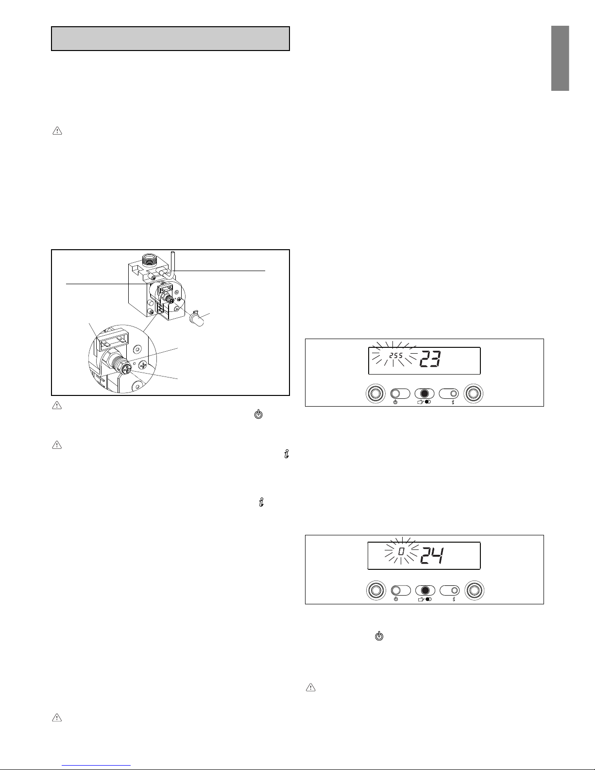
23
English
GAS TYPE (P. 1)
Modify the set value as follows:
- press ENTER to access the parameter modification function.
When ENTER is pressed, the previously set value starts flashing
(fig. 43 C.A.I. -MIX C.S.I.; fig. 75 R.A.I. - MIX R.S.I.)
- turn the domestic hot water temperature selector to change the
value (1 MTN - 2 LPG)
- press ENTER to confirm the new value. The digits stop flashing.
MAXIMUM POWER ADJUSTMENT (P. HH)
- Turn the domestic hot water temperature selector till HH is shown
- Use a fork spanner CH10 to turn the maximum power to the
value indicated in the multigas table
- Wait for the pressure on the pressure gauge to stabilise at the
required value.
MINIMUM POWER ADJUSTMENT (P. LL)
- Turn the domestic hot water temperature selector till LL is shown
- Taking care not to press on the inner shaft, turn the red
domestic hot water minimum adjustment screw with a
screwdriver until the pressure gauge reads the value indicated
in the multigas table.
MAXIMUM HEATING ADJUSTMENT POSSIBILITY (P. 23)
C.A.I.-MIX C.S.I.: check that the pressure read on the pressure
gauge corresponds to that shown on the multigas table.
R.A.I.-MIX R.S.I.: check that the pressure read on the display is 255.
If it does not, carry out the adjustment operations described below:
- turn the domestic hot water temperature selector till 23 is shown.
Wait for the boiler to start
- press ENTER to access the parameter modification function
- C.A.I.-MIX C.S.I.: turn the domestic hot water selector until the
pressure gauge corresponds to that indicated in the multigas table
- R.A.I.-MIX R.S.I.: turn the domestic hot water selector until the
value on the display is 255 (fig. 77)
- press ENTER to confirm the new value.
MINIMUM HEATING ADJUSTMENT POSSIBILITY (P. 24)
C.A.I.-MIX C.S.I.: check that the pressure read on the pressure
gauge corresponds to that shown on the multigas table.
R.A.I.-MIX R.S.I.: check that the pressure read on the display is 0.
If it does not, carry out the adjustment operations described below:
- turn the domestic hot water temperature selector till 24 is shown.
Wait for the boiler to start)
- press ENTER to access the parameter modification function
- C.A.I.-MIX C.S.I.: turn the domestic hot water selector until the pressure
gauge corresponds to that indicated in the multigas table
- R.A.I.-MIX R.S.I.: turn the domestic hot water selector until the
value on the display is 0 (fig. 78)
- press ENTER to confirm the new value.
Exit the CALIBRATION & SERVICE function by pressing ESCAPE.
The boiler returns to the “- -” (OFF) status.
To reset, press the
button.
- Reconnect the compensation inlet to the air distribution box
(MIX C.S.I.-MIX R.S.I.)
- Disconnect the pressure gauge and tighten the pressure tap
screw.
After adjusting the gas valve, seal it with sealing wax.
After making adjustments:
- return the temperature set with the ambient thermostat to the
required position
- close the panel
- put back the shell.
The boiler has already been factory adjusted by the manufacturer.
For LPG gas: the boiler has been regulated in I3B/P category
(G30). If you need to regulate in I3+ or I3P categories (G31) exclude
pressure regulator.
If a new adjustment is required, for example, after extraordinary
maintenance, replacing the gas valve or converting from natural
gas to LPG, proceed as follows.
Maximum and minimum power, minimum and maximum
heating, must be adjusted in the indicated sequence by
qualified staff.
- Unscrew the lower cover fixing screw (C, fig. 3c)
- Pull the cover towards you and remove (A-B) (fig. 4a)
- Loosen the two fixing screws (D) and remove the shell (fig. 3a)
- Lift up the panel and turn it forwards
- Loosen the pressure tap screw downline from the gas valve by
about two turns and connect the pressure gauge to it
- Carefully prise out the cap protecting the adjustment screws
with a screwdriver
- Disconnect the compensation inlet from the air distribution box
(MIX C.S.I.-MIX R.S.I., fig. 76)
CALIBRATION & SERVICE operations must be performed with
the boiler in the OFF position. To do this, press the
button
until the display shows “- -” (fig. 40 C.A.I. -MIX C.S.I.; fig. 72
R.A.I. - MIX R.S.I.).
During parameter modification operations, the “select
functions” button acts as an ENTER (confirm) button, the
button acts as an ESCAPE button. If no confirmation is given
within 10 seconds, the value is discarded and returns to the
previously set one.
Setting the password
Press and hold down the operating mode button and the
button
together for about 10 seconds. The display will look like fig. 41
(C.A.I. -MIX C.S.I.) and fig. 73 (R.A.I. - MIX R.S.I.).
Enter the password for accessing the parameter modifications
function by turning the domestic hot water temperature selector to
the required value.
The password is located on the back side of the control panel.
Confirm by pressing ENTER.
Calibration phases
Turn the domestic hot water selector to sequentially scroll the
CALIBRATION & SERVICE phases:
- 1 gas type
- 2 boiler power (MIX C.S.I.-MIX R.S.I., parameter not used in
this phase)
- 10 domestic hot water mode (parameter not used in this phase)
- 3 insulation level of building (only if external sensor is
connected)
- 45 inclination of thermoregulation curve (OTC), only if external
sensor is connected)
- HH boiler at maximum power
- LL boiler at minimum power
- 23 maximum heating adjustment possibility
- 24 minimum heating adjustment possibility.
The parameters must be modified, by professionally
qualified personnel, only if absolutely necessary. The
manufacturer refuses any responsibility in the case of
incorrect setting of the parameters.
15.
ADJUSTMENTS
Compensation cap
(only for MIX C.S.I. - MIX R.S.I.)
Fig. 76
Maximum pressure
adjusting nut
Safety
cap
Faston
connectors
Minimum pressure
adjusting nut
Pressure tap downline
from the gas valve
Fig. 77
Fig. 78
Page 24

24
17.
CHECKING COMBUSTION PARAMETERS
To ensure the product remains in perfect working order, and to
comply with current legislation, systematically check the boiler at
regular intervals.
To analyse combustion, proceed as follows:
- access the CALIBRATION & SERVICE phase by setting the
password as indicated in chapter “Adjustments”
- turn the domestic hot water temperature selector to maximum
heating power (parameter HH).
The boiler works at maximum power for 4 minutes.
C.A.I.-R.A.I.:
- The hole for inserting analysis instruments must be made in the
section of straight pipe immediately after it leaves the hood in
compliance with current law (A, fig. 81a).
MIX C.S.I.-MIX R.S.I.:
- use appropriate tools on the taps fitted to the air distribution box
after removing the cover (B, fig. 81b/c).
The first tap is connected to the air intake circuit and detects
infiltration of fumes from concentric outlets; the second is directly
connected to the fumes outlet circuit and is used to detect
combustion parameters and efficiency.
The fumes analysis probe must be fully inserted.
IMPORTANT: the function that switches off the boiler when water
temperature reaches a maximum of about 90 °C is still enabled
during the combustion analysis phase.
18.
SERIAL NUMBER PLATE
Pmw = 6 bar T= 60 °C
Qn =
0694/00
N.
230 V ~ 50 Hz
****
NOx:
D: l/min
Gas type:
Gas category:
05/BB1
05/CA3
IP
P. min.
Pms = 3 bar T= 90 °C
Pn =
ç =
Gas type
Gas
category
It is easy to convert from one gas family to another even after the
boiler has been installed. This operation must be performed by
professionally qualified staff. The boiler is designed to work with
natural gas or LPG. The product plate indicates which fuel it has
been fitted out to use.
It is possible to convert the boiler from one kind of gas to the other
using kits which can be supplied on request:
- natural gas to LPG conversion kit
- LPG to natural gas conversion kit.
To disassemble, proceed as follows:
- disconnect the boiler from the power supply and close the gas
tap
- remove the components to access to the internal parts of the
boiler (fig. 79-80)
- disconnect the two burner thermostat fastons from the wiring
(MIX C.S.I.-MIX R.S.I.)
- disconnect the sparkplug cable
- remove the lower cable holder from the air distribution box (MIX
C.S.I.-MIX R.S.I.)
- remove the screws fixing the burner and remove the latter with
the burner thermostat (MIX C.S.I.-MIX R.S.I.) and the sparkplug
attached
- remove the nozzles and washers with a socket or fork wrench
and replace them with the ones in the kit
Use the washers contained in the kit even for washerless
collectors.
- put back the burner into the combustion chamber and tighten
the screws fixing it to the gas collector
- position the cable holder with the sparkplug cable in its seat on
the air distribution box (MIX C.S.I.-MIX R.S.I.)
- reconnect the burner thermostat terminals to the wiring (MIX
C.S.I.-MIX R.S.I.)
- reconnect the spark plug cable
- remount components previously removed
- power the boiler and open the gas tap (with the boiler working,
check there are no leaks in the gas supply circuit).
Programme the “Gas type” parameter and adjust the boiler as
described in the “Adjustments” chapter.
The boiler may only be converted by qualified staff.
After conversion, adjust the boiler again as shown in the
relative paragraph and apply the new rating plate contained
in the kit.
16.
GAS CONVERSION
DHW operation
CH operation
Qn nominal capacity
Pn nominal power
IP protection level
P. min minimum pressure
Pmw DHW maximum pressure
Pms CH maximum pressure
T temperature
ηη
ηη
η working efficiency
D specific capacity
NOx NOx value class
Page 25

25
Français
1.
AVERTISSEMENTS ET
MESURES DE SECURITE
Les chaudières produites dans nos ateliers sont construites
en soignant particulièrement chaque composant de façon à
protéger l’utilisateur et l’installateur contre tout risque
d’accident. Nous recommandons donc au personnel qualifié
de faire très attention aux branchements électriques, après
chaque intervention, surtout au niveau de la partie mise à nue
des conducteurs, qui ne doit jamais sortir du bornier et en
évitant autant que possible le contact avec les parties soustension du conducteur.
Ce manuel fait partie intégrante de l’appareil: vérifiez s’il
accompagne toujours l’appareil, même en cas de cession à
un autre propriétaire ou utilisateur ou de transfert sur une
autre installation. Si vous perdez ou abîmez le manuel, veuillez
en demander un autre au Service Après-vente de votre région.
Le montage de la chaudière et toutes les autres opérations
d’entretien ou de dépannage ne doivent être confiées qu’à
du personnel qualifié conformément aux indications des lois
en vigueur et de leur mise à jour.
Les opérations d’entretien de la chaudière doivent être
effectuées au moins un fois par an après avoir été
programmées à l’avance avec le Service Après-vente.
Nous conseillons au monteur d’expliquer correctement à
l’utilisateur le fonctionnement de l’appareil et les mesures
fondamentales de sécurité.
Cette chaudière ne doit être destinée qu’à l’usage pour lequel
elle a été construite. Toute responsabilité contractuelle et
extracontractuelle est exclue en cas de préjudices causés à
des personnes, des animaux ou des choses à la suite d’une
erreur de montage, de réglage, d’entretien ou d’un usage
impropre.
Cet appareil sert à produire de l’eau chaude et doit être branché
sur une installation de chauffage et(ou) un réseau de
distribution d’eau chaude sanitaire, compatible à ses
performances et à sa puissance.
Après avoir ôté l’emballage, vérifiez si son contenu est intègre
et complet. En cas de divergence, adressez vous au revendeur
auquel vous avez acheté l’appareil.
L’évacuation de la soupape de sécurité de l’appareil doit être
raccordée sur un système de récolte et d’évacuation adéquat.
Le constructeur de l’appareil n’est pas responsable des
préjudices éventuellement causés par la soupape de sécurité.
Pendant toute la durée de vie de l’installation, les dispositifs
de sécurité et de réglage automatique des appareils ne doivent
pas être modifiés, si ce n’est pas le constructeur ou le
fournisseur.
En cas de panne et(ou) de mauvais fonctionnement de
l’appareil, arrêtez-le et ne tentez aucune réparation ou
intervention directe.
Au moment de l’installation il est indispensable d’informer
l’utilisateur que:
- en cas de fuites d’eau, il doit fermer l’alimentation en eau et
appeler rapidement le Service Après-vente
- C.A.I.-MIX C.S.I.: il doit vérifier régulièrement que l’icône
du tableau de commande ne s’éclaire pas. Ce symbole
indique que la pression de l’installation hydraulique n’est
pas correcte. En cas de besoin, charger l’installation de la
façon indiquée au chapitre “Fonctions de la chaudière”
- R.A.I.-MIX R.S.I.: il doit vérifier régulièrement que, sur le
tableau de commande, la valeur de pression soit entre 1 et
1,5 bar. En cas de besoin, charger l’installation de la façon
indiquée au chapitre “Fonctions de la chaudière”
- si la chaudière n’a pas servi pendant longtemps, nous
conseillons d’appeler le Service Après-vente pour effectuer
au moins les opérations suivantes:
• placer l’interrupteur général de l’installation et l’interrupteur
principal de l’appareil sur “éteint”
• fermer les robinets du combustible et de l’eau de
l’installation thermique (C.A.I.-MIX C.S.I.-R.A.I.-MIX R.S.I.)
et du sanitaire (C.A.I.-MIX C.S.I. uniquement)
• vider l’installation thermique (C.A.I.-MIX C.S.I.-R.A.I.-MIX
R.S.I.) et sanitaire (C.A.I.-MIX C.S.I. uniquement) en cas de
risque de gel.
Par mesure de sécurité n’oubliez pas que:
il est fermement déconseillé de laisser les enfants ou les
personnes handicapées
il est dangereux d’actionner les dispositifs électriques, comme
les interrupteurs, les électroménagers, etc.. si vous sentez
La chaudière ne doit être montée que par du personnel
professionnellement qualifié. La chaudière existe dans les
modèles suivants:
Exclusive C.A.I. est une chaudière de type B
11BS pour le chauffage
et la production d’eau chaude sanitaire; Exclusive R.A.I. est une
chaudière de type B
11BS pour le chauffage. Ce type d’appareil ne
peut être monté ni dans les chambres, ni dans les salles de bains
et(ou) douches ni dans des endroits où se trouvent des cheminées
ouvertes sans arrivée d’air indépendante.
Exclusive MIX C.S.I. est une chaudière de type C pour le chauffage
et la production d’eau chaude sanitaire; Exclusive MIX R.S.I. est
une chaudière murale de type C en mesure de fonctionner dans
différentes conditions:
- SITUATION A: uniquement chauffage. La chaudière ne fournit
pas d’eau chaude sanitaire
- SITUATION B: uniquement chauffage avec raccordement d’un
chauffe eau externe, géré par un thermostat, pour la préparation
d’eau chaude sanitaire
- SITUATION C: uniquement chauffage avec raccordement d’un
chauffe eau externe (dispositif prêt à-monter à la demande),
géré par une sonde, pour la préparation d’eau chaude sanitaire.
Si vous raccordez un ballon d’une autre marque que la nôtre,
vérifiez si la résistance de la sonde NTC utilisée a les
caractéristiques suivante: 10 kOhm à 25°C, B 3435 ±1%.
Selon le type d’installation choisi, vous devez configurer le
paramètre “mode sanitaire”. Vous trouverez la description du
paramètre et de ses opérations de configuration à la page 43.
Ce type d’appareil peut être installé dans n’importe quelle pièce sans
limitations dues aux conditions d’aération et au volume de la pièce.
2.
MONTAGE DE LA CHAUDIERE
Modèle Type Catégorie Puissance
C.A.I. Combinée B11BS 24 kW
C.A.I. Combinée B11BS 28 kW
R.A.I. Uniquement chauffage B11BS 28 kW
MIX C.S.I. Combinée C 26 kW
MIX C.S.I. Combinée C 30 kW
MIX C.S.I. Combinée C 35 kW
MIX R.S.I. Uniquement chauffage C 30 kW
MIX R.S.I. Uniquement chauffage C 35 kW
une odeur de combustible ou de combustion. En cas de fuites
de gaz, aérez la pièce en ouvrant complètement portes et
fenêtres, fermez le robinet général du gaz; faites intervenir
rapidement le personnel qualifié du Service Après-vente
ne touchez pas l’appareil en ayant des parties du corps
mouillées ou humides et(ou) les pieds nus
appuyez sur la touche
jusqu’à ce que l’afficheur montre
“- -” et débranchez la chaudière du réseau d’alimentation
électrique en plaçant l’interrupteur bipolaire se l’installation
sur “éteint” avant d’effectuer les opérations de nettoyage
il est interdit de modifier les dispositifs de sécurité ou de
réglage sans l’autorisation ou les indications du constructeur
dispositif de sécurité fumées (uniquement pour C.A.I. et
R.A.I.): la chaudière est equipée d’un système de contrôle de
la bonne évacuation des produits de la combustion
(thermostat fumées) qui, en cas d’anomalie, intervient en
positionnant la chaudière en état d’arrêt. Pour revenir aux
conditions de fonctionnement appuyez sur la touche
. Si
l’anomalie persiste, appelez un technicien qualifié du Service
Après-vente. Le dispositif contrôlant la bonne évacuation de
fumées ne doit jamais être mis hors d’usage. Si vous
remplacez le dispositif ou les parties défectueuses n’utilisez
que des pièces détachées originales.
ne tirez pas sur les câbles électriques, ne tirez pas dessus, ne
les détachez pas et ne les tordez pas même si la chaudière
est débranchée du réseau électrique
évitez de boucher ou de réduire les dimensions des ouvertures
d’aération du lieu d’installation. C.A.I. et R.A.I. uniquement:
les ouvertures d’aération sont indispensables pour que la
combustion s’effectue correctement
ne laissez ni récipients,ni substances inflammables dans la
pièce où est installé l’appareil
ne laissez pas les éléments de l’emballage à la portée des
enfants
n’utilisez pas l’appareil pour des buts autres que celui auquel
il est destiné
ne posez aucun objet sur la chaudière
l’appareil de l’alimentation électrique il est interdit d’interve-
nir sur les éléments scellés.
Page 26
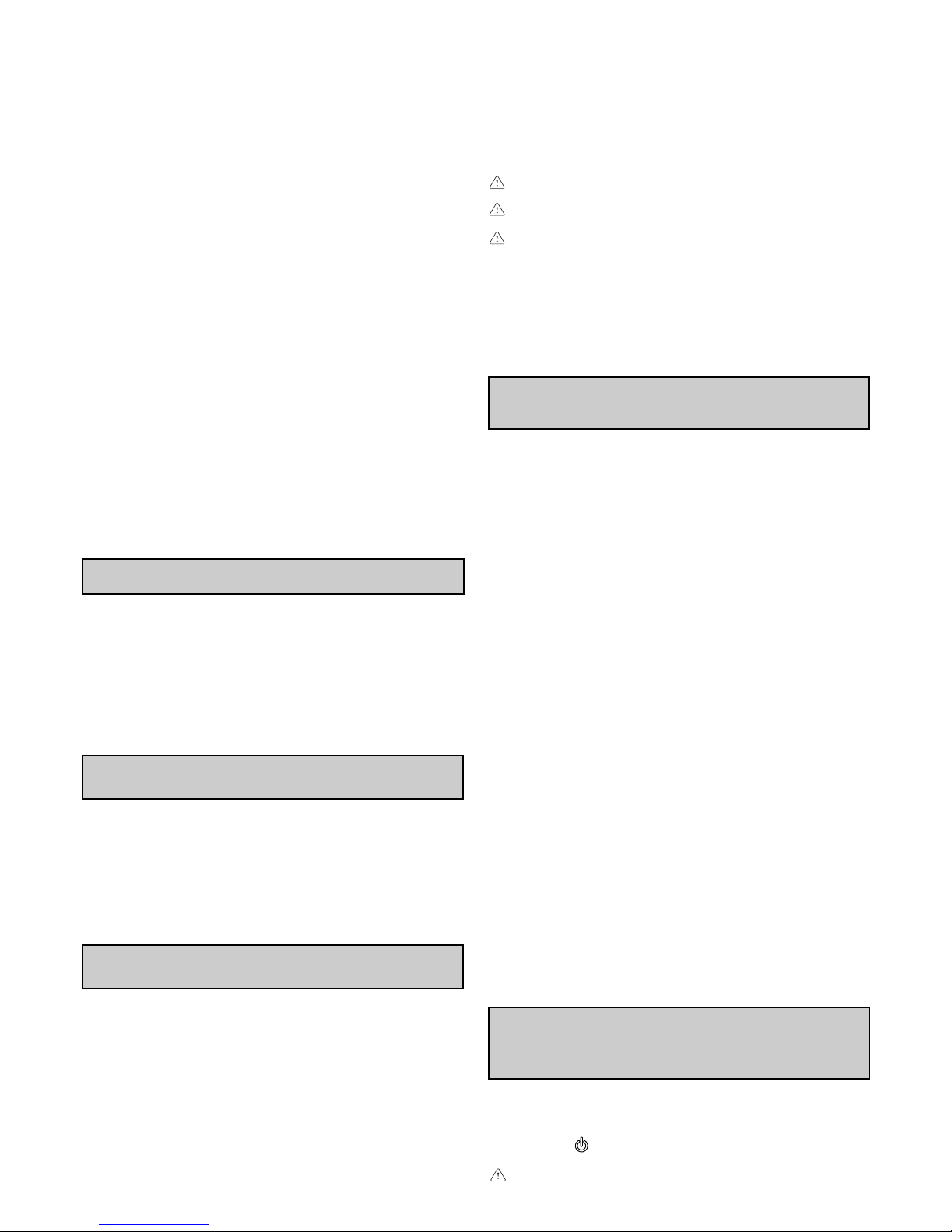
26
Pour accéder aux branchements électriques, procédez de la sorte:
- dévisser la vis (C) de la cache tuyauterie (fig. 3c)
- sortez le couvercle de son logement en le tirant vers vous (A-B)
(fig. 4a)
- ôtez le manteau en dévissant les vis de fixation (D) (fig. 3a)
- soulevez la façade de bord et faites-la pivoter vers l’avant
- ouvrez les couvre-bornier en les faisant glisser dans le sens
des flèches (fig. 4b: E branchements haute tension 230 V, F
branchements basse tension, G branchements sonde sanitaire
uniquement MIX R.S.I.-R.A.I.).
Le branchement sur le secteur doit s’effectuer à travers un dispositif de
séparation avec ouverture omnipolaire d’au moins 3,5 mm (EN 603351, catégorie III).
L’appareil fonctionne avec un courant alternatif de 230 Volt/Volt/
50 Hz et une puissance électrique de 85 W (C.A.I.-R.A.I.), 120 W
5.
BRANCHEMENT ELECTRIQUE
Avant de raccorder l’appareil sur le réseau du gaz, vérifiez que:
• les normes en vigueur son respectées
• le type de gaz est celui pour lequel l’appareil est équipé
• les tuyauteries sont propres.
La canalisation de gaz est prévue à l’extérieur. Si le tuyau traverse
le mur, il doit passer à travers le trou central dans le bas du gabarit.
Nous conseillons de monter sur la ligne du gaz un filtre de
dimensions adéquates si le réseau de distribution contient des
particules solides. Au terme du montage, vérifiez sur les joints
exécutés sont étanches conformément aux normes en vigueur.
4.
RACCORDEMENTS DU GAZ
La position et la dimension des raccordements hydrauliques sont
indiquées sur la figure 2:
A - retour chauffage 3/4”
B - départ chauffage 3/4”
C - raccordement du gaz 3/4”
D - sortie sanitaire 1/2” (C.A.I.-MIX C.S.I. uniq.)
E - entrée sanitaire 1/2” (C.A.I.-MIX C.S.I. uniq.)
F - plaque de support
G - gabarit de pré-montage
Si la dureté de l’eau dépasse 28°Fr, nous vous conseillons
d’utiliser un adoucisseur afin d’empêcher les dépôts calcaires.
3.
RACCORDEMENTS HYDRAULIQUES
Selon l’accessoire d’évacuation des fumées utilisé, elle est classée
dans les catégories suivantes: C12,C12x; C22; C32,C32x; C42,C42x;
C52,C52x (26kW et 30kW uniquement); C62,C62x; C82,C82x.
L’installation doit être effectuée conformément aux indications des lois
en vigueur et de leurs mises à jour.
Pour placer correctement l’appareil, n’oubliez pas que:
• il ne doit jamais être placé au-dessus d’une cuisinière ou d’un
autre dispositif de cuisson
• pour permettre d’accéder à l’intérieur de la chaudière pour effectuer
les opérations d’entretien normales vous devez garantit les
espaces minimum prévus pour l’installation: au moins 2,5 cm de
chaque côté et 20 cm au-dessous de l’appareil
• ne laissez pas de récipients et de substances inflammables
dans la pièce où est installé l’appareil
• les parois sensibles à la chaleur (par exemple celles en bois)
doivent être protégées par une isolation appropriée.
La chaudière est équipée en standard de plaques de support
avec un gabarit de pré-montage intégré (fig. 2).
Pour le montage, effectuez les opérations suivantes:
• fixez la plaque de support de la chaudière (F) avec le gabarit de
pré-montage (G) au mur et à l’aide d’un niveau à bulle contrôlez
s’ils sont parfaitement horizontaux
• tracez les 4 trous (Ø 6 mm) prévus pour fixer la plaque de support
de la chaudière (F) et les 2 trous (Ø 4 mm) pour fixer le gabarit
de pré-montage (G)
• vérifiez si toutes les mesures prises sont exactes puis percez le
mur à l’aide d’une perceuse munie d’un foret ayant le diamètre
indiqué précédemment
• fixez la plaque au mur avec le gabarit intégré à l’aide des
chevilles fournies
• effectuez les raccordements hydrauliques.
Lorsque la chaudière est installée, vous pouvez retirer les vis D
1
(fig. 3a).
Lorsque les opérations de montage de la chaudière et de
raccordement sur les réseaux d’eau et de gaz sont achevées, posez
le couvercle des raccords (A-B, fig. 3b) en veillant à ce que ses
crochets s’enfilent dans les boutonnières prévues à cet effet au bas
de la chaudière. Fixez le couvercle des raccords en utilisant la vis C
(fig. 3c) contenue dans l’enveloppe de la documentation.
(26kW MIX C.S.I.), 150 W (30kW MIX C.S.I.-MIX R.S.I.) et 160 W
(35kW MIX C.S.I.-MIX R.S.I.). Il est conforme à la norme EN 60335-1.
Le branchement sur une mise à la terre sûre, conforme aux normes
en vigueur, est obligatoire
.
Nous conseillons en outre de respecter le branchement d’une
phase neutre (L-N). La chaudière peut fonctionner avec une
alimentation phase-neutrre ou phase-phase. Pour les
alimentations flottantes, c’est-à-dire dépourvues de mise à la terre, vous devez utiliser un transformateur d’isolation avec un
secondaire ancrée à la terre.
Le conducteur de mise à la terre doit mesurer 2 cm de plus
que les autres.
Il est interdit d’utiliser les tuyaux de gaz et(ou) d’eau pour
effectuer la mise à la terre des appareils électriques.
L’installateur est responsable de la mise à la terre de
l’appareil; le fabricant décline toute responsabilité en cas
de préjudices causés par une erreur ou l’absence de mise
à la terre.
Pour le branchement électrique utilisez le câble d’alimentation
fourni. Le thermostat d’ambiance et(ou) l’horloge-programmateur
se branchent de la façon indiquée sur le schéma électrique de la
page 100.
Si vous remplacez le câble d’alimentation, utilisez un câble de
type HAR H05V2V2-F, 3 x 0,75.
Après avoir effectué les raccordements hydrauliques, vous pouvez
remplir l’installation de chauffage. Cette opération doit s’effectuer
sur l’installation froide en procédant de la sorte:
• ouvrez de 2 ou 3 tours le bouchon du purgeur d’air automatique
(A, fig. 5a et 5b);
• vérifiez si le robinet d’entrée de l’eau froide est ouvert (MIX
C.S.I. - C.A.I. uniquement)
• ouvrez le robinet de remplissage (C, dans la chaudière sur MIX
C.S.I. - C.A.I., extérieur sur MIX R.S.I. - R.A.I.) jusqu’à ce que la
pression indiquée par l’hydromètre (D) soit comprise entre 1 et
1,5 bars (zone bleue) (fig. 5a et 5b).
Au terme du remplissage, refermez le robinet de remplissage. La
chaudière est munie d’un séparateur d’air et ne requiert donc
aucune opération manuelle. Le brûleur s’allume uniquement au
terme de la phase de purge d’air.
REMARQUE (MIX C.S.I. - C.A.I. uniquement): même si la
chaudière est munie d’un dispositif de remplissage
semiautomatique, vous devez effectuer le premier remplissage
de l’installation en agissant sur le robinet C.
REMARQUE (MIX R.S.I. - R.A.I. uniquement): la chaudière est
dépourvue de robinet de remplissage pour installation murale,
prévoyez un robinet externe ou vérifiez si le ballon exterieur en
possède un.
Pour vider l’installation procédez de la sorte:
• éteignez la chaudière
• raccordez le tube en caoutchouc, fourni en standard, sur la
soupape de vidage de la chaudière (E, fig. 5a et 5b)
• desserrez à la main la soupape (E)
• videz les points les plus bas de l’installation.
Vidange de l’installation sanitaire (MIX C.S.I. - C.A.I. uniquement)
Si un risque de gel se présente, videz l’installation
sanitaire en procédant de la sorte:
• fermez le robinet général du réseau hydrique
• ouvrez tous les robinets d’eau chaude et froide
• videz les points les plus bas de l’installation.
ATTENTION
L’évacuation de la soupape de sécurité (B) de l’appareil doit être
raccordée sur un système de récolte adéquat. Le constructeur de
l’appareil n’est pas responsable des préjudices éventuellement
causés par l’intervention de la soupape de sécurité.
6.
REMPLISSAGE ET VIDANGE DE
L’INSTALLATION
7.
EVACUATION PRODUITS DE LA
COMBUSTION ET ASPIRATION DE L’AIR
(C.A.I.-R.A.I.)
La chaudière est munie d’un système contrôlant la bonne
évacuation des produits de la combustion - thermostat fumées
(12, fig. 82a-82b pag. 91-92) qui, en cas d’anomalie, verrouille la
chaudière. Pour revenir aux conditions de fonctionnement appuyez
sur la touche . Si l’anomalie persiste, appelez un technicien
qualifié du Service Après-vente
Pour l’évacuation des produits de la combustion consultez
les normes en vigueur.
Page 27

27
Français
8.
EVACUATION PRODUITS DE LA
COMBUSTION ET ASPIRATION DE L’AIR
(MIX C.S.I.-MIX R.S.I.)
CONFIGURATIONS POSSIBLES D’EVACUATION (fig. 7)
La chaudière est homologuée pour les configurations suivantes de
l’évacuation:
C12 Evacuation murale concentrique. Les tuyaux peuvent être
indépendants au départ de la chaudière mais les sorties doivent être
concentriques ou assez proches pour subir les mêmes conditions
de vente (pas plus de 50 cm)
C22 Evacuation concentrique en conduit de fumées commun (aspiration
et évacuation dans le même conduit)
C32 Evacuation concentrique sur le toit. Sorties comme C12
C42 Evacuation et aspiration en conduits de fumées communs séparés,
mais soumis au mêmes conditions de vent
C52 Evacuation et aspiration murale ou sur le toit et de toute façon dans
des zones de pression différente. L’évacuation et l’aspiration ne
doivent jamais se trouver sur des murs opposés
C62 Evacuation et aspiration réalisées en tuyaux du commerce et certifiés
séparément (1856/1)
C82 Evacuation en conduit de cheminée simple ou commune et aspiration
murale.
Pour l’évacuation des produits de la combustion consultez les
normes en vigueur.
La chaudière est vendue sans kit d’évacuation des fumées/
d’aspiration de l’air car vous pouvez utiliser les accessoires pour
les appareils à chambre étanche à tirage forcé les mieux adaptés
aux caractéristiques de l’installation.
Pour extraire les fumées et rétablir l’air comburant de la chaudière
il est indispensable d’utiliser des tuyauteries originales et
d’effectuer correctement le raccordement, de la façon indiquée
par les instructions fournies avec les accessoires pour fumées.
Vous pouvez raccorder plusieurs appareils sur un seul conduit de
cheminée à condition qu’ils aient tous une chambre étanche. La
chaudière est un appareil de type C (à chambre étanche) qui doit
avoir un raccordement sûr sur le conduit d’évacuation des fumées
et sur celui d’aspiration de l’air comburant, débouchant tous deux
à l’extérieur; sans eux l’appareil ne peut pas fonctionner.
Conduits coaxiaux (ø 60-100)
Les conduits coaxiaux peuvent être orientés dans la direction la
mieux adaptée aux exigences de l’installation, mais il faut faire
très attention à la température extérieure et à la longueur du conduit.
Consultez les graphiques pour établir s’il est ou non obligatoire
de prévoir un récupérateur de condensats.
En cas de fonctionnement avec une température de la
chaudière inférieure à 50°C (par exemple avec ne sonde
extérieure), la longueur maximum autorisée doit être réduite
d’un mètre.
Prévoyez une inclinaison du conduit d’évacuation des fumées
de 1% vers le récupérateur de condensats.
pertes de charge (m)
coude 45° coude 90°
longueur maximum
conduit coaxial ø 60-100 (m)
3,4026 MIX C.S.I.
0,5 0,85
3,4030 MIX C.S.I.
3,4030 MIX R.S.I.
235 MIX C.S.I.
Longueur maxi conduits coaxiaux ø 60-100 26 MIX C.S.I.
Longueur de l’évacuation (m)
Température extérieure (°C)
RÉCUPÉRATEUR DE
CONDENSATS OBLIGATOIRE
RÉCUPÉRATEUR DE
CONDENSATS FACULTATIF
Fig. 9a
CONDUITS COAXIAUX (ø 60-100)
Fig. 8a
Conduit
coaxial
Collier
Récupérateur
de condensats
Siphon évacuation
condensats
Il est obligatoire d’utiliser des conduits rigides; les joints entre
les éléments doivent être hermétiques et tous les composants
doivent résister à la température, aux condensats et aux
sollicitations mécaniques.
Le dispositif contrôlant la bonne évacuation de fumées ne
doit jamais être mis hors d’usage. Si vous remplacez le
dispositif ou les parties défectueuses n’utilisez que des pièces
détachées originales.
Les conduits d’évacuation non isolés sont des sources de
danger potentielles.
Les ouvertures pour l’air comburant doivent être conformes
aux normes ne vigueur.
En cas de formation de condensats, vous devez calorifuger le
conduit d’évacuation.
Fig. 6b montre la chaudière vue d’en haut avec les cotes de
référence pour l’écartement de la sortie des fumées, par
rapport à la plaque de support de la chaudière.
Le récupérateur de condensats ne doit être monté que sur le
conduit des fumées, à 0,85 m maximum de la chaudière;
raccordez le siphon du récupérateur de condensats sur une
évacuation des eaux blanches.
Les conduits d’évacuation non isolés sont des sources de
danger potentielles.
La chaudière adapte automatiquement la ventilation en
fonction du type d’installation et de la longueur du conduit. Ne
bouchez pas, même partiellement, le conduit d’aspiration de
l’air comburant.
Longueur maxi conduits coaxiaux ø 60-100
30 MIX C.S.I. - 30 MIX R.S.I.
Longueur maxi conduits coaxiaux ø 60-100
35 MIX C.S.I. - 35 MIX R.S.I.
Longueur de l’évacuation (m)
Longueur de l’évacuation (m)
Température extérieure (°C)
Température extérieure (°C)
Fig. 9c
Fig. 9b
RÉCUPÉRATEUR DE
CONDENSATS OBLIGATOIRE
RÉCUPÉRATEUR DE
CONDENSATS FACULTATIF
RÉCUPÉRATEUR DE
CONDENSATS OBLIGATOIRE
RÉCUPÉRATEUR DE
CONDENSATS FACULTATIF
Conduits coaxiaux (ø 80-125)
La chaudière est aménagée pour être raccordée sur des conduits
d’évacuation/aspiration coaxiaux ayant l’ouverture pour l’aspiration d’air fermée.
Les évacuations coaxiales peuvent être orientées dans la direction la mieux adaptée aux besoins de la pièce, en respectant les
longueurs maximum indiquées sur le tableau.
35 MIX R.S.I.
2
Page 28
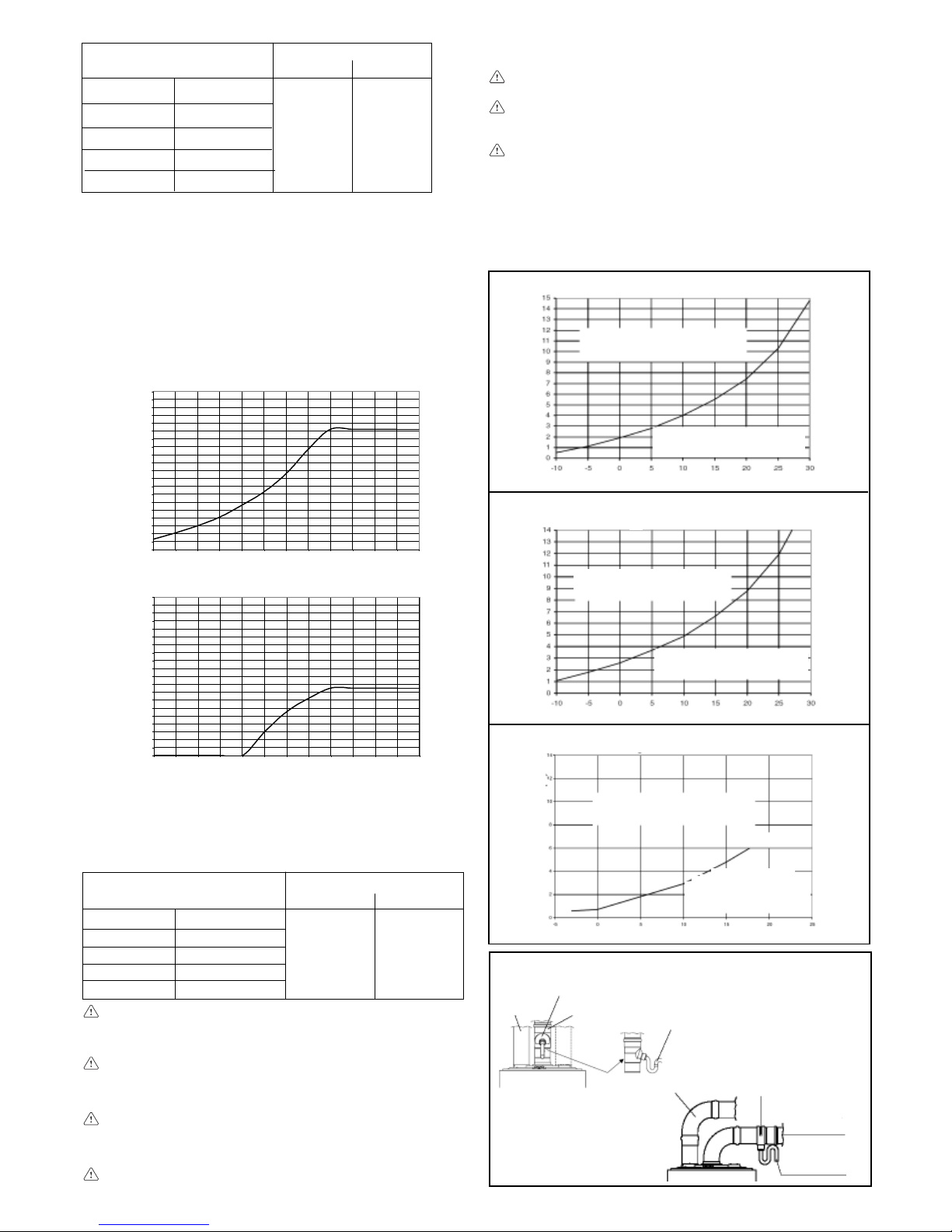
28
pertes de charge (m)
coude 45° coude 90°
longueur des conduits verticale
et horizontale (m)
7,626 MIX C.S.I.
1,35 2,2
7,630 MIX C.S.I.
7,630 MIX R.S.I.
4,2
35 MIX C.S.I.
Faites très attention à la température extérieure et à la longueur
du conduit. Consultez les graphiques pour établir si l’usage du
récupérateur de condensats est ou n’est pas obligatoire.
Si la chaudière fonctionne à des températures inférieures à 60°C,
le récupérateur de condensats est obligatoire.
Si vous utilisez un récupérateur de condensats, prévoyez une
inclinaison de la conduite d’évacuation des fumées de 1% vers le
récupérateur. Raccordez le siphon du récupérateur de condensats
sur une évacuation des eaux blanches. Les conduits d’évacuation
non isolés sont des sources de danger potentielles.
Conduits dédoublés (ø 80)
Les conduits dédoublés peuvent être orientés dans la direction la
mieux adaptée aux exigences de l’installation, mais il faut faire
très attention à la température du lieu d’installation et à la longueur
du conduit des fumées. Pour effectuer le montage suivez les
instructions fournies avec le kit.
Si l’installation prévoit des tronçons d’évacuation à l’extérieur,
pour calculer la longueur maximum autorisée sans évacuation
des condensats, utilisez la température extérieure au lieu de
celle du lieu d’installation de la chaudière.
En cas de fonctionnement à des températures inférieures à
50°C (par exemple sur les installations munies d’une sonde
extérieure) la longueur maximum autorisée sans récupérateur
de condensats doit être réduite de 0,85 mètres.
Le récupérateur de condensats ne doit être monté que sur le
conduit des fumées, à 0,85 m maximum de la chaudière;
raccordez le siphon du récupérateur de condensats sur une
évacuation des eaux blanches.
Prévoyez une inclinaison du conduit d’évacuation des fumées
de 1% vers le récupérateur de condensats.
0,0
0,5
1,0
1,5
2,0
2,5
3,0
3,5
4,0
4,5
5,0
5,5
6,0
6,5
7,0
7,5
8,0
8,5
9,0
9,5
10,0
-30-25-20-15-10-5 0 5 1015202530
Longueur de
l’évacuation (m)
Température extérieure (°C)
26 - 30kW
RÉCUPÉRATEUR DE
CONDENSATS OBLIGATOIRE
RÉCUPÉRATEUR DE
CONDENSATS FACULTATIF
0,0
0,5
1,0
1,5
2,0
2,5
3,0
3,5
4,0
4,5
5,0
5,5
6,0
6,5
7,0
7,5
8,0
8,5
9,0
9,5
10,0
-30-25-20-15-10-5 0 5 1015202530
Longueur de
l’évacuation (m)
Température extérieure (°C)
35kW
RÉCUPÉRATEUR DE
CONDENSATS OBLIGATOIRE
RÉCUPÉRATEUR DE
CONDENSATS FACULTATIF
Longueur maxi conduits dédoublés ø 80 26 MIX C.S.I.
Longueur de l’évacuation (m)
Température extérieure (°C)
Longueur de l’évacuation (m)
Température extérieure (°C)
Longueur maxi conduits dédoublés ø 80
30 MIX C.S.I. - 30 MIX R.S.I.
Longueur de l’évacuation (m)
Température extérieure (°C)
Fig. 10c
Fig. 10b
Fig. 10a
RÉCUPÉRATEUR DE
CONDENSATS OBLIGATOIRE
RÉCUPÉRATEUR DE
CONDENSATS FACULTATIF
RÉCUPÉRATEUR DE
CONDENSATS OBLIGATOIRE
RÉCUPÉRATEUR DE
CONDENSATS FACULTATIF
RÉCUPÉRATEUR DE
CONDENSATS OBLIGATOIRE
RÉCUPÉRATEUR DE
CONDENSATS FACULTATIF
longueur maximum
conduit dédoublé (ø 80) (m)
15 + 1526 MIX C.S.I.
14 + 1430 MIX C.S.I.
14 + 1430 MIX R.S.I.
6 + 635 MIX C.S.I.
0,85
0,5
pertes de charge (m)
coude 45° coude 90°
La chaudière adapte automatiquement la ventilation en
fonction du type d’installation et de la longueur des conduits.
Ne bouchez pas même partiellement les conduits.
Si la longueur des conduits diffère de celle indiquée sur le
tableau ci-contre:
- pour le modèle 26 MIX C.S.I., la somme des conduits
d’aspiration et d’évacuation doit être inférieure à 30 mètres,
mais la longueur de chaque conduit ne peut pas dépasser
18 mètres
- pour les modèles 30 MIX C.S.I. - MIX R.S.I., la somme des
conduits d’aspiration et d’évacuation doit être inférieure à
28 mètres, mais la longueur de chaque conduit ne peut pas
dépasser 17 mètres
- pour le modèle 35 MIX C.S.I. - MIX R.S.I., la somme des
conduits d’aspiration et d’évacuation doit être inférieure à
12 mètres, mais la longueur de chaque conduit ne peut pas
dépasser 8 mètres.
CONDUITS DEDOUBLES (ø 80)
Récupérateur
de condensats
Récupérateur
de condensats
Siphon évacuation
condensats
Siphon évacuation
condensats
Conduit
aspiration air
Conduit
aspiration air
Conduit
évacuation
fumées
Conduit
évacuation
fumées
Fig. 8b
Pour monter le kit suivez les instructions qui l’accompagnent.
Pour traverser le mur, percez un trou de Ø 140 mm.
35 MIX R.S.I. 4,2
35 MIX R.S.I.
6 + 6
Longueur maxi conduits dédoublés ø 80
35 MIX C.S.I. - 35 MIX R.S.I.
Page 29

29
Français
99
99
9
..
..
.
DONNEES TECHNIQUES
Débit thermique nominal chauffage/sanitaire* (Hi) kW 26,70 31,30 28,80 33,20 37,80
kcal/h 22.962 26.918 24.768 28.552 32.508
Puissance thermique nominale chauffage/sanitaire* kW 24,03 28,30 26,21 30,38 35,31
kcal/h 20.666 24.334 22.539 26.125 30.362
Débit thermique minimal chauffage (Hi) kW 8,30 10,70 8,50 9,80 9,95
kcal/h 7.138 9.202 7.310 8.428 8.557
Puissance thermique minimale chauffage kW 7,05 9,21 7,70 8,86 9,18
kcal/h 6.060 7.923 6.623 7.619 7.898
Débit thermique minimal sanitaire* (Hi) kW 8,30 8,70 8,50 9,80 9,95
kcal/h 7.138 7.482 7.310 8.428 8.557
Puissance thermique minimale sanitaire* kW 7,05 7,49 7,70 8,86 9,18
kcal/h 6.060 6.442 6.623 7.619 7.898
Rendement utile Pn maxi - Pn mini % 90,0-84,9 90,4-86,1 91,0-90,6 91,5-90,4 93,4-92,3
Rendement utile 30% % 89,9 90,3 91,9 92,2 94,5
Puissance électrique W 85 85 120 150 160
Tension d’alimentation V - Hz 230-50 230-50 230-50 230-50 230-50
Degré de protection IP X5D X5D X5D X5D X5D
Pertes au niveau de cheminée et manteau avec brûleur éteint % 0,07-0,80 0,07-0,80 0,80-0,07 0,80-0,07 0,80-0,07
Excercice de chauffage
Pression - Température maximum bar-°C 3-90 3-90 3-90 3-90 3-90
Pression minimum pour fonctionnement standard bar 0,25-0,45 0,25-0,45 0,25-0,45 0,25-0,45 0,25-0,45
Plage de sélection de la températuree °C 40-80 40-80 40-80 40-80 40-80
Pompe: prévalence maximum disponible pour l’installation mbar 300 300 300 300 340
avec un débit de l/h 1000 1000 1000 1000 1000
Vase d’expansion à membrane l 8 8 8 8 10
Pré-charge du vase d’expansion (chauffage) bar 1 1 1 1 1
Excercice sanitaire*
Pression maxi bar 6 6 6 6 6
Pression mini bar 0,15 0,15 0,15 0,15 0,15
Débit spécifique selon EN625 l/min - - 11,85 14 Quantité d’eau chaude avec: Δt 30° C l/min 11,5 13,5 - - 16,9
Débit minieau sanitaire l/min 2 2 2 2 2
Plage de sélection de la température eau sanitaire °C 35-60 35-60 35-60 35-60 35-60
Régulateur de flux l/min 10 12 11 13 15
Pression du gaz
Catégorie II2H3+ II2H3+ II2H3+ II2H3+ II2H3+
Pression nominale gaz méthane (G20) mbar 20 20 20 20 20
Pression nominale gaz liquide GPL (G30/G31) mbar 28-30/37 28-30/37 28-30/37 28-30/37 28-30/37
Raccordements hydrauliques
Entrée-sortie chauffage Ø 3/4” 3/4” 3/4” 3/4” 3/4”
Entrée-sortie sanitaire (MIX C.S.I. - C.A.I.) Ø 1/2” 1/2” 1/2” 1/2” 1/2”
Départ-retour ballon (MIX R.S.I. - R.A.I.) Ø - 3/4” - 3/4” 3/4”
Entrée gaz Ø 3/4” 3/4” 3/4” 3/4” 3/4”
Dimensions de la chaudière
Hauteur mm 740 740 740 740 780
Largeur mm 400 450 400 450 500
Profondeur mm 332 332 332 332 332
Poids chaudière kg 3 0 33 (C.A.I.) 34 36 (MIX C.S.I.) 43 (MIX C.S.I.)
Poids chaudière kg - 32 (R.A.I.) - 35 (MIX R.S.I.) 42 (MIX C.S.I.)
Performances du ventilateur
Prévalence résiduelle tuyaux concentriques 0,85 m mbar - - 0,2 0,2 0,2
Prévalence résiduelle chaudière sans tuyaux mbar - - 0,35 0,35 1,15
Débits (G20)
Débit air Nm3/h 46,914 54,996 48,34 54,107 60,724
Débit fumées Nm3/h 49,591 58,135 51,23 57,44 64,515
Débit en masse des fumées (max - min) gr/s 16,92-15,01 19,84-17,98 17,45-10,24 19,54-13,64 21,93-13,17
Tuyaux évacuation des fumées
Diamètre mm 130 140 - - -
Tuyaux évacuation des fumées concentriques
Diamètre mm - - 60-100 60-100 60-100
Longueur maximum m - - 3,40 3,40 2,00
Perte causée par l’introduction d’un coude 90°/45° m - - 0,85/0,5 0,85/0,5 0,85/0,5
Diamètre du trou de traversée du mur mm - - 105 105 105
Diamètre mm - - 80-125 80-125 80-125
Longueur maximum m - - 7,6 7,6 4,2
Perte causée par l’introduction d’un coude 90°/45° m - - 2,2/1,35 2,2/1,35 2,2/1,35
Diamètre du trou de traversée du mur mm - - 140 140 140
Tuyaux évacuation des fumées séparés
Diamètre mm - - 80 80 80
Longueur maximum m - - 15+15 14+14 6+6
Perte causée par l’introduction d’un coude 90°/45° m - - 0,8/0,5 0,8/0,5 0,8/0,5
NOx classe 3 classe 2 classe 2 classe 3 classe 3
Valeurs d’émission avec le débit maximum et minimum du gaz G20 **
Maximum CO s.a. infèrieur à p.p.m. 100 130 100 90 90
CO
2
% 6,40 6,40 6,70 6,90 7,00
NOx s.a. infèrieur à p.p.m. 160 210 190 140 120
Δt fumées °C 113 106 133 132 116
Minimum CO s.a. infèrieur à p.p.m. 130 90 120 100 120
CO
2
% 2,23 2,40 3,35 2,90 3,05
NOx s.a. infèrieur à p.p.m. 100 150 140 110 100
Δt fumées °C 71 70 63 72 62
* Les valeurs du sanitaire sont exclusivement celles des modèles C.A.I. - MIX C.S.I.
** C.A.I. - R.A.I.: vérification effectué avec Ø 130 (24kW), Ø 140 (28kW) - longueur 0,5m
** MIX C.S.I. - MIX R.S.I.: vérification effectué avec tuyau concentric Ø 60-100 - longueur 0,85m - température de l’eau 800-60°C.
C.A.I.
24kW
C.A.I.
R.A.I.
28kW
MIX C.S.I.
26kW
MIX C.S.I.
MIX R.S.I.
30kW
MIX C.S.I.
MIX R.S.I.
35kW
Page 30

30
10.
TABLEAUX MULTIGAZ
Paramètres Méthane GPL
(G20) Butane Propane
(G30) (G31)
C.A.I. - R.A.I.
Indice de Wobbe inférieur (à 15°C-1013 mbar) MJ/m3S 45,67 80,58 70,69
Pouvoir calorifique inférieur MJ/m3S 34,02 116,09 88
MJ/kgs - 45,65 46,34
Pression nominal d’alimentation mbar 20 28-30 37
(mm H2O) (203,9) (285,5-305,9) (377,3)
Pression minimum d’alimentation mbar 13,5
(mm H2O) (137,7) -
24 kW C.A.I.
Brûleur principal (12 buses) Ø mm 1,3 0,77 0,77
Débit gaz maximum chauffage Sm3/h 2,82 - -
kg/h - 2,10 2,07
Débit gaz maximum sanitaire Sm3/h 2,82 - -
kg/h - 2,10 2,07
Débit gaz minimum chauffage Sm3/h 0,88 - -
kg/h - 0,65 0,64
Débit gaz minimum sanitaire Sm3/h 0,88 - -
kg/h - 0,65 0,64
Pression maxi en aval du robinet en chauffage mbar 11,80 28,00 36,00
mm H2O 120,33 285,52 367,10
Pression maxi en aval du robinet en sanitaire mbar 11,80 28,00 36,00
mm H2O 120,33 285,52 367,10
Pression mini en aval du robinet en chauffage mbar 1,30 3,10 4,00
mm H2O 13,26 31,61 40,79
Pression mini en aval du robinet en sanitaire mbar 1,30 3,10 4,00
mm H2O 13,26 31,61 40,79
28 kW C.A.I. - R.A.I.
Brûleur principal (14 buses) Ø mm 1,3 0,77 0,77
Débit gaz maximum chauffage Sm3/h 3,31 - -
kg/h - 2,47 2,43
Débit gaz maximum sanitaire* Sm3/h 3,31 - -
kg/h - 2,47 2,43
Débit gaz minimum chauffage Sm3/h 1,13 - -
kg/h - 0,84 0,83
Débit gaz minimum sanitaire* Sm3/h 0,92 - -
kg/h - 0,69 0,68
Pression maxi en aval du robinet en chauffage mbar 11,90 28,00 35,80
mm H2O 121,35 285,52 365,06
Pression maxi en aval du robinet en sanitaire* mbar 11,90 28,00 35,80
mm H2O 121,35 285,52 365,06
Pression mini en aval du robinet en chauffage mbar 1,50 3,80 5,30
mm H2O 15,30 38,75 54,05
Pression mini en aval du robinet en sanitaire* mbar 1,10 2,50 3,30
mm H2O 11,22 25,49 33,65
* Les valeurs du sanitaire sont exclusivement celles des modèles C.A.I. - MIX C.S.I.
Page 31

31
Français
Paramètres Méthane GPL
(G20) Butane Propane
(G30) (G31)
MIX C.S.I. - MIX R.S.I.
Indice de Wobbe inférieur (à 15°C-1013 mbar) MJ/m3S 45,67 80,58 70,69
Pouvoir calorifique inférieur MJ/m3S 34,02 116,09 88
MJ/kgs - 45,65 46,34
Pression nominal d’alimentation mbar 20 28-30 37
(mm H2O) (203,9) (285,5-305,9) (377,3)
Pression minimum d’alimentation mbar 13,5
(mm H2O) (137,7) -
26 kW MIX C.S.I.
Brûleur principal (13 buses) Ø mm 1,35 0,78 0,78
Débit gaz maximum chauffage Sm3/h 3,05 - -
kg/h - 2,27 2,24
Débit gaz maximum sanitaire Sm3/h 3,05 - -
kg/h - 2,27 2,24
Débit gaz minimum chauffage Sm
3
/h 0,90 - -
kg/h - 0,67 0,66
Débit gaz minimum sanitaire Sm3/h 0,90 - -
kg/h - 0,67 0,66
Pression maxi en aval du robinet en chauffage mbar 10,60 27,90 35,50
mm H2O 108,09 284,50 362,00
Pression maxi en aval du robinet en sanitaire mbar 10,60 27,90 35,50
mm H2O 108,09 284,50 362,00
Pression mini en aval du robinet en chauffage mbar 1,10 2,60 3,60
mm H2O 11,22 26,51 36,71
Pression mini en aval du robinet en sanitaire mbar 1,10 2,60 3,60
mm H2O 11,22 26,51 36,71
30 kW MIX C.S.I. - MIX R.S.I.
Brûleur principal (15 buses) Ø mm 1,35 0,76 0,76
Débit gaz maximum chauffage Sm3/h 3,51 - -
kg/h - 2,62 2,58
Débit gaz maximum sanitaire* Sm3/h 3,51 - -
kg/h - 2,62 2,58
Débit gaz minimum chauffage Sm3/h 1,04 - -
kg/h - 0,77 0,76
Débit gaz minimum sanitaire* Sm3/h 1,04 - -
kg/h - 0,77 0,76
Pression maxi en aval du robinet en chauffage mbar 10,10 27,50 35,40
mm H2O 102,99 280,42 360,98
Pression maxi en aval du robinet en sanitaire* mbar 10,10 27,50 35,40
mm H2O 102,99 280,42 360,98
Pression mini en aval du robinet en chauffage mbar 1,00 2,80 3,60
mm H2O 10,20 28,55 36,71
Pression mini en aval du robinet en sanitaire* mbar 1,00 2,80 3,60
mm H2O 10,20 28,55 36,71
35 kW MIX C.S.I. - MIX R.S.I.
Brûleur principal (16 buses) Ø mm 1,4 0,8 0,8
Débit gaz maximum chauffage Sm3/h 4,00 - -
kg/h - 2,98 2,94
Débit gaz maximum sanitaire Sm3/h 4,00 - -
kg/h - 2,98 2,94
Débit gaz minimum chauffage Sm3/h 1,05 - -
kg/h - 0,78 0,77
Débit gaz minimum sanitaire Sm3/h 1,05 - -
kg/h - 0,78 0,77
Pression maxi en aval du robinet en chauffage mbar 9,60 27,30 35,40
mm H2O 97,89 278,38 360,98
Pression maxi en aval du robinet en sanitaire mbar 9,60 27,30 35,40
mm H2O 97,89 278,38 360,98
Pression mini en aval du robinet en chauffage mbar 0,70 2,10 2,80
mm H2O 7,14 21,41 28,55
Pression mini en aval du robinet en sanitaire mbar 0,70 2,10 2,80
mm H2O 7,14 21,41 28,55
* Les valeurs du sanitaire sont exclusivement celles des modèles C.A.I. - MIX C.S.I.
Page 32

32
11.
ALLUMAGE ET FONCTIONNEMENT
(C.A.I. - MIX C.S.I.)
Description des commandes
Sélecteur de température de l’eau du chauffage: permet de
configurer la valeur de la température de l’eau de chauffage.
Sélecteur de température de l’eau sanitaire: permet de
configurer la valeur de la température de l’eau de voulue.
Touche de fonction:
- ON chaudière alimentée électriquement, en attente de
demande de fonctionnement (
- )
- OFF chaudière alimentée électriquement mais par
disponible pour le fonctionnement
- RESET permet de rétablir le fonctionnement après une anomalie du fonctionnement
Touche du mode de fonctionnement: permet de choisir le mode
de fonctionnement le mieux adapté à vos besoins (
hiver -
hiver comfort- été - été comfort).
Touche Info: permet d’afficher en séquence les informations
sur l’état du fonctionnement de l’appareil.
Touche de remplissage de l’installation: si vous l’enfoncez, la
chaudière remplit automatiquement l’installation jusqu’à la
valeur de la pression voulue (entre 1 et 1,5 bars).
Dans les versions combinées, la chaudière produit du chauffage
et de l’eau chaude sanitaire.
Le tableau de commande (fig. 13) contient les principales fonctions
de contrôle et de gestion de la chaudière.
Fig. 13
Description des icônes
échelle graduée de la température de l’eau de chauffage
avec icône de fonction chauffage
échelle graduée de la température de l’eau sanitaire
avec icône de fonction sanitaire
icône anomalie (pour détails, consultez page 36)
icône reset (pour détails, consultez page 36)
valeur de la pression
icône du branchement de la sonde extérieure
température du chauffage/sanitaire
ou
anomalie du fonctionnement (par ex. 10 - anomalie
manque de flamme)
indicateur de sélection des fonctions (se place en face
du type de fonctionnement choisi:
hiver - hiver
comfort - été - été comfort)
icône du fonctionnement du brûleur
icône de la fonction antigel active
icône de la fonction remplissage de l’installation
icône du besoin de remplissage
Fig. 14
Sélecteur de
température de
l’eau sanitaire
Touche du
mode de
fonctionnement
Touche fonction
ON-OFF-RESET
Touche de
remplissage
installation
Sélecteur de
température de
l’eau du chauffage
Touche
INFO
Page 33

33
Français
Réglage de la température de l‘eau de chauffage
Si vous faites tourner le sélecteur A (fig. 18), après avoir placé le
sélecteur de fonction sur hiver
ou hiver comfort , vous
pouvez régler la température de l’eau de chauffage.
En sens horaire la température augmente, en sens contraire elle
diminue. Les segments de la barre graphique s’éclairent (tous les
5°C) au fur et à mesure que la température augmente. L’afficheur
montre la valeur de la température sélectionnée. Si, lorsque vous
choisissez la température de l’eau de chauffage, vous entrez dans
la plage de réglage S.A.R.A. (de 55 à 65 °C) le symbol
et
l’échelle graduée correspondante clignotent. Pour en savoir
davantage sur la fonction S.A.R.A. consultez la page 35. L’afficheur
montre la valeur de la température sélectionnée.
Réglage de la température de l‘eau de chauffage avec une
sonde extérieure branchée
Lorsqu’une sonde extérieure est installée, le système choisit
automatiquement la valeur de la température de départ et adapte
rapidement la température ambiante en fonction des variations
de la température extérieure. Seul le segment central de la barre
apparaît éclairé (fig. 19). Si vous voulez modifier la valeur de la
température, en l’augmentant ou la diminuant par rapport à celle
que la carte électronique calcule automatiquement, vous pouvez
agir sur le sélecteur de température de l’eau de chauffage. En
sens horaire la valeur de correction de la température augmente,
en sens antihoraire elle diminue. Les segments de la barre
graphique s’éclairent (à chaque niveau de confort); la plage de
correction est comprise entre - 5 et + 5 niveaux de confort (fig. 19).
Lorsque vous choisissez le niveau de confort, l’afficheur montre,
dans l’aire des chiffres, le niveau de confort, sur la barre graphique
le segment correspondant (fig. 20).
Réglage de la température de l‘eau sanitaire
Pour régler la température de l’eau sanitaire faites tourner le sélecteur B
(fig. 21) en sens horaire la température augmente, en sens contraire elle
diminue. Les segments de la barre graphique s’éclairent (tous les 3°C)
au fur et à mesure que la température augmente. L’afficheur montre la
valeur de la température sélectionnée.
Pendant le choix de la température, de chauffage ou bien sanitaire,
l’afficheur montre la valeur que vous êtres en train de sélectionner.
Lorsque votre choix est fait, après 4 secondes environ, la
modification est mémorisée et l’afficheur montre à nouveau la
température de départ détectée par la sonde.
Allumage de l’appareil
Pour allumer la chaudière vous devez:
- accéder au robinet du gaz à travers les fentes du couvre-raccords
situé au bas de la chaudière
- ouvrir le robinet de gaz, en faisant pivoter en sens antihoraire la
poignée, pour laisser arriver le combustible (fig. 15)
- mettre la chaudière sous tension.
Lorsqu’elle est alimentée chaudière effectue automatiquement
un série de vérifications et l’afficheur montre plusieurs chiffres et
lettres. Si la vérification s’achève correctement, environ 4 secondes
après la fin du cycle, la chaudière est prête à fonctionner.
L’afficheur apparaît comme sur la figure 16.
Si le résultat de la vérification est négatif, la chaudière ne fonctionne
pas et le chiffre “0” clignote sur l’afficheur.
Dans ce cas appeler le Service Après-vente.
La chaudière se rallume dans l’état dans lequel se trouvait
avant d’être éteinte: si la chaudière se trouvait en mode hiver
comfort lorsqu’elle a été éteinte, elle se rallume en mode hiver
comfort; si elle se trouvait dans l’état OFF, l’afficheur montre
deux segments en son centre (fig. 17). Appuyez sur la touche
pour activer le fonctionnement.
- appuyez sur la touche de sélection des fonctions jusqu’à ce
que l’indicateur se place sur la fonction voulue selon le type
de fonctionnement choisi.
- HIVER
: si le sélecteur se trouve dans cette position, vous
activez les fonctions d’eau de chauffage et d’eau chaude
sanitaire. Dans cette position, en chauffage, la fonction S.A.R.A.
(cf. chapitre “Fonctions de la chaudière”) est active. Pendant la
production d’eau chaude sanitaire, la chaudière a activé le
stabilisateur de température, garantissant ainsi la continuité
de la production même si les prélèvements sont minimum ou
si la température de l’eau entrante est déjà chaude. Cela permet
d’éviter les oscillations de température dues à l’extinction/
allumage du brûleur.
- HIVER COMFORT
: si le sélecteur se trouve sur cette
fonction, vous activez non seulement la traditionnelle fonction
de chauffage et l’eau chaude sanitaire mais aussi la fonction
de préchauffage, qui permet de conserver l’eau chaude contenue
dans l’échangeur sanitaire afin de réduire les temps d’attente
avant les prélèvements. Dans cette position les fonctions
S.A.R.A., Booster et Préchauffage sanitaire sont actives (cf.
chapitre “Fonctions de la chaudière”).
- ÉTÉ
: si le sélecteur se trouve dans cette position, vous
activez la seule fonction traditionnelle d’eau chaude sanitaire.
- ÉTÉ COMFORT
: si le sélecteur se trouve dans cette position,
la chaudière ne fournit que de l’eau chaude sanitaire avec le
stabilisateur de température pour les petits prélèvements. Cette
fonction est idéale pour les périodes de l’année et les régions
où la température de l’eau du réseau hydrique est déjà tiède.
Dans ces conditions la température de l’eau chaude produite
parune chaudière avec uniquement les fonctions traditionnelles
(cf. ÉTÉ e et HIVER COMFORT) pourrait être instable.
Fig. 15
position
d’ouverture
Fig. 16
Fig. 17
Fig. 18
Fig. 21
A
Fig. 19
°C
+ 4/5
+ 3
+ 2
+ 1
0
- 1
- 2
- 3
- 4/5
Fig. 20
B
Page 34

34
Si cette condition se présente, la pression de l’installation n’est
pas correcte, la chaudière continue cependant à fonctionner
normalement. Appuyez sur la touche
pour activer la procédure
de remplissage. Si vous appuyez encore sur la touche de
remplissage de l’installation
vous pouvez interrompre la
séquence de remplissage. Pendant la phase de remplissage,
l’afficheur montre en cascade les gouttes de l’icône de remplissage
et la valeur croissante de la pression (fig. 27).
A la fin du remplissage, l’afficheur montre pendant un instant
l’icône
puis il s’éteint.
Remarque: pendant le remplissage, la chaudière n’exécute
aucune autre fonction, par exemple si vous effectuez un
prélèvement sanitaire, la chaudière n’est pas en mesure de fournir
l’eau chaude tant que le remplissage n’est pas achevé.
Remarque: si la valeur de pression de charge de l’installation
atteint 0.6 bars, la valeur sur le display commence à clignoter
(fig. 28b); si elle descende au-dessous du minimum de sécurité
(0.3 bar), l’afficheur montre l’anomalie 41 (fig. 28a) pendant un
court instant, après quoi, si l’anomalie persiste, il montre le code
d’anomalie 40 (cf. chapitre “Anomalies”).
Si anomalie 40 s’affiche, procédez au rétablissement en appuyant
sur
puis sur pour activer la procédure de remplissage de
l’installation. Si vous devez répéter plusieurs fois la procédure
de remplissage de l’installation, nous vous conseillons de vous
adresser au Service Après-vente pour qu’il vérifie l’étanchéité
de l’installation (vois s’il n’y a pas de fuites).
Informations
Si vous appuyez sur la touche
, l’afficheur s’éteint et seule
l’inscription InFO reste (fig. 29). En appuyant sur la touche vous
pouvez afficher certaines informations utiles au fonctionnement
de la chaudière. Chaque fois que vous appuyez sur la touche
vous passez à l’information suivante. Si vous n’appuyez plus sur
la touche
le système sort automatiquement de la fonction.
Liste Info:
Info 0 affiche l’inscription InFO (fig. 29)
Info 1 uniquement si la sonde extérieure est branchée, affiche
la température extérieure (par ex. 12 °C) (fig. 30). Les
valeurs affichés sont comprises entre - 40 °C et 40 °C. Audelà de ces valeurs, l’afficheur montre “- -”
Fig. 27
Mise en service de la chaudière
Réglez le thermostat d’ambiance sur la température voulue
(environ 20 °C). Si de la chaleur est demandée, la chaudière
démarre et l’afficheur montre l’icône
(fig. 22). La chaudière
reste alors en marche jusqu’à ce que les températures configurées
soient atteintes, puis elle se met en stand-by. Si une anomalie
se présente à l’allumage ou pendant le fonctionnement, la
chaudière effectue un “arrêt de sécurité”.
L’afficheur montre la flamme
et le code d’anomalie d’affiche avec
l’inscription
(fig. 23). Pour connaître la description et la procédure
de rétablissement des anomalies consultez le chapitre “Anomalies”.
Extinction
Extinction provisoire
En cas de courtes absences, appuyez sur la touche
pour
éteindre la chaudière. Dans la zone centrale de l’afficheur
apparaissent deux segments (fig. 17). De la sorte l’alimentation
électrique et l’alimentation en combustible sont actives mais la
chaudière est protégée par les systèmes:
- antigel (fig. 24): lorsque la température de l’eau de la chaudière
descend au-dessous des valeurs de sécurité, le circulateur et
le brûleur s’activent à la puissance minimum pour ramener la
température de l’eau à la valeur de sécurité (35 °C). Le symbole
s’éclaire sur l’afficheur.
- antiverrouillage du circulateur: un cycle de fonctionnement
s’active toutes les 24 heures.
Extinction pendant de longues périodes
En cas d’absence prolongée, appuyez sur la touche
pour
éteindre la chaudière (fig. 17). Dans la zone centrale de l’afficheur
apparaissent deux segments. Placez l’interrupteur général de
l’installation sur “éteint”. Fermez le robinet de gaz placé sous la
chaudière en faisant pivoter la poignée en sens horaire (fig. 25).
Dans ce cas les systèmes antigel et antiverrouillage sont
désactivés. Videz l’installation thermique ou protégez-la de
façon adéquate avec du liquide antigel de qualité. Videz
l’installation sanitaire.
Fig. 23
Fig. 22
Fig. 24
Fig. 25
robinet
fermé
Fonctions de la chaudière
Remplissage semi-automatique
La chaudière est équipée d’un dispositif de remplissage semi
automatique qui s’active à l’aide de la touche lorsque l’afficheur
montre l’icône correspondante (fig. 26).
Fig. 26
Fig. 29
Fig. 28a
Fig. 28b
Fig. 30
Page 35

35
Français
Fig. 34
Fig. 35
Info 2 affiche la pression de charge de l’installation (fig. 31)
Info 3 affiche la température de chauffage configurée (fig. 32)
Info 4 affiche la température de l’eau sanitaire configurée (fig. 33).
Fonction S.A.R.A.
Si vous avez sélectionné la position “hiver” vous pouvez activer la
fonction S.A.R.A. (Système Automatique Réglage Ambiance).
Si vous sélectionnez, en faisant tourner le sélecteur de température
de l’eau de chauffage, une température comprise entre 55 et 65
°C, vous activez le système d’autoréglage S.A.R.A.: selon la
température configurée sur le thermostat d’ambiance et le temps
nécessaire pour l’atteindre, la chaudière varie automatiquement
la température de l’eau de chauffage, en réduisant le temps de
fonctionnement et en garantissant un fonctionnement plus
confortable et une économie d’énergie.
Fig. 31
Fig. 32
Fig. 33
Fonction S.A.R.A. BOOSTER
Si vous sélectionnez la position “hiver comfort”, vous activez la
fonction S.A.R.A. du circuit de chauffage Booster, permettant
d’atteindre plus rapidement la température ambiante voulue.
Fonction PRÉ-CHAUFFAGE SANITAIRE
Si vous sélectionnez la position “hiver comfort” vous activez la
fonction Préchauffage sanitaire du circuit de chauffage. Cette
fonction sert à conserver la température de l’eau sanitaire
contenue dans la chaudière et de réduire ainsi sensiblement la
durée de l’attente à chaque prélèvement. Pour limiter la
consommation d’énergie, dans les régions où les températures
ne sont pas particulièrement basses, nous vous conseillons de
sélectionner la fonction
.
Dans ce cas, les fonctions Booster et Préchauffage sanitaire ne
sont pas active.
Anomalies
Lorsqu’une anomalie de fonctionnement se présente, la flamme
s’éteint sur l’afficheur, qui montre un code clignotant et,
simultanément ou pas les icônes et . Le tableau cidessous vous donne la description des anomalies.
(D) Définitive
(T) Temporaire. Dans cet état de fonctionnement, la chaudière tente de résoudre elle-même l’anomalie
(°) Lire REMARQUE dans la page suivante.
(*) Pour anomalie “pression installation insuffisante”, procédez aux opérations de remplissage de l’installation décrites au chapitre “Fonctions de la
chaudière”.
DESCRIPTION DE L’ANOMALIE Code Icône Icône
alarme
VERROUILLAGE MANQUE FLAMME (D) 10 OUI NON
THERMOSTAT LIMITE (D) 20 OUI NON
THERMOSTAT BRÛLEUR (D) (MIX C.S.I) 21 OUI NON
THERMOSTAT FUMEES (D) (C.A.I.) 22 OUI OUI
ÉVACUATION FUMÉES OU PRESSOSTAT AIR (D) (MIX C.S.I.) 30 OUI NON
ÉVACUATION FUMÉES OU PRESSOSTAT AIR (T) (MIX C.S.I.) 31 NON OUI
PRESSION INSTALLATION INSUFFISANTE (D*) 40 OUI NON
PRESSION INSTALLATION INSUFFISANTE (T*) 41 NON OUI
TRANSDUCTEUR PRESSION EAU (D) 42 OUI OUI
FAUSSE FLAMME (D) 50 OUI OUI
CARTE ÉLECTRONIQUE (D) 51-59 OUI OUI
SONDE SANITAIRE 1 (T°) 60 NON OUI
SONDE PRIMAIRE (T) 71 NON OUI
THERMOSTAT BASSE TEMPÉRATURE (T) 77 OUI OUI
Page 36

36
Rétablissement des anomalies
Attendez environ 10 secondes avant de rétablir les conditions
de fonctionnement. Ensuite, procédez de la sorte:
1) Affichage uniquement de l’icône
L’affichage de indique le diagnostic d’une anomalie de
fonctionnement que la chaudière tente de résoudre par elle-même
(arrêt temporaire). Si la chaudière ne se remet pas à fonctionner
normalement, l’afficheur montre deux situations:
situation A (fig. 36)
disparition de
, apparition de l’icône et d’un autre code
d’alarme. Dans ce cas, procédez de la façon décrite au point 2.
situation B (fig. 37)
avec apparition de l’icône et d’un autre code d’alarme.
Dans ce cas, procédez de la façon décrite au point 3.
2) Affichage uniquement de l’icône
(fig. 38)
Appuyez sur la touche
pour rétablir le fonctionnement. Si la
chaudière effectue l’allumage et reprend son fonctionnement
normal, l’arrêt est le fruit du hasard. Si le verrouillage se répète
plusieurs fois, il est préférable de vous adresser au Service Aprèsvente.
3) Affichage des icônes
et (fig. 39)
Demandez l’intervention du Service Après-vente.
Remarque: Anomalie sonde circuit sanitaire - 60: la chaudière
fonctionne normalement mais elle ne garantit pas la stabilité de la
température de l’eau du circuit sanitaire qui est toujours fournie à
une température d’environ 50°C. Le code anomalie ne s’affiche
qu’avec la chaudière en stand-by.
12.
PROGRAMMATION DES PARAMÈTRES
Cette chaudière est équipée de cartes électroniques de nouvelle
génération, qui permettent, en configurant/modifiant des
paramètres de fonctionnement de la machine, de mieux la
personnaliser afin de répondre aux différents besoins de
l’installation et(ou) de l’usager. Les paramètres configurables sont
indiqués sur le tableau de la page suivante.
Les opérations de configuration des paramètres doivent
s’effectuer ave la chaudière en position OFF. Pour cela appuyez
sur la touche
jusqu’à ce que l’afficheur montre “- -” (fig. 40).
Pendant la modification des paramètres la touche “mode de
fonctionnement” sert de touche ENTER (confirmation) et la
touche
sert de touche ESCAPE (sortie). Si aucune confirmation
n’est donnée dans les 10 secondes qui suivent, la valeur n’est
pas mémorisée et la valeur configurée auparavant s’applique.
Configuration du code d’accès
Appuyez en même temps sur la touche “mode de fonctionnement”
et sur la touche
pendant 10 secondes environ. L’afficheur apparaît
comme sur la fig. 41. Saisissez le code d’accès aux fonctions de
modification des paramètres en faisant tourner le sélecteur de
température d’eau sanitaire jusqu’à la valeur voulue. Le code d’accès
à la configuration des paramètres se trouve dans le tableau de
commande. Confirmez l’entrée en appuyant sur la touche ENTER.
Modification des paramètres
Si vous faites tourner le sélecteur température de l’eau sanitaire
(fig. 42) vous faites défiler en séquence les codes à deux chiffres
des paramètres du tableau. Lorsque vous avez trouvé le paramètre
que vous voulez modifier, procédez de la sorte:
- appuyez sur la touche ENTER pour accéder à la modification
de la valeur du paramètre. Lorsque vous appuyez sur la touche
ENTER la valeur configurée auparavant clignote (fig. 43)
- faites tourner le sélecteur de température de l’eau sanitaire
pour porter la valeur à la valeur voulue
- confirmez la nouvelle valeur configurée avec la touche ENTER.
Les chiffres cessent de clignoter (fig. 44)
- sortez en appuyant sur la touche ESCAPE.
La chaudière se remet dans l’état “- -” (éteint). Pour rétablir le
fonctionnement appuyez sur la touche
(fig. 40).
Fig. 36
Fig. 37
Fig. 38
“anomalie
temporaire”
Fig. 39
Fig. 40
Fig. 41
Fig. 42
Fig. 43
Fig. 44
“anomalie
temporaire”
“anomalie
définitive”
“anomalie
définitive”
ENTER
ESCAPE
valeur du
paramètre
numéro du
paramètre
Page 37

37
Français
C.A.I.: parametrès configurables
N° DESCRIPTION PARAMETRES UNITE DE MINI MAXI DEFAULT PARAMETRES
PAR. MESURE (configuré en usine) (configuré par le Service Technique)
1 TYPE DE GAZ 1 Méthane 1-2
2 GAZ LIQUIDE
3 Méthane France
3 DEGRÉ DE CALORIFUGEAGE DE L’ÉDIFICE (+) (*) min 5 20 5
10 MODE SANITAIRE 0 (OFF) 1
1 (Instantanée)
2 (Miniaccumulation)
3 (Ballon exterieur avec thermostat)
4 (Ballon exterieur avec sonde)
11 POINT DE CONSIGNE MAXIMUM CIRCUIT SANITAIRE ° C 40 60 60
12 PARAMÈTRE NON UTILISABLE SUR CE MODÈLE NE PAS MODIFIER LA CONFIGURATION 60
13 PARAMÈTRE NON UTILISABLE SUR CE MODÈLE NE PAS MODIFIER LA CONFIGURATION 80
14 PARAMÈTRE NON UTILISABLE SUR CE MODÈLE NE PAS MODIFIER LA CONFIGURATION 5
20 MODE CHAUFFAGE 0 (OFF) 1
1 (ON)
2 (vannes de zone +
panneau de commande à distance)
21 POINT DE CONSIGNE MAXIMUM CHAUFFAGE ° C 40 80 80
22 PARAMÈTRE NON UTILISABLE SUR CE MODÈLE NE PAS MODIFIER LA CONFIGURATION 40
28 TEMPOR. PUISASNCE MAXI CHAUFFAGE RÉDUITE min 0 20 15
29 TEMPOR. EXTINCTION FORCÉ E CHAUFFAGE min 0 20 3
30 FONCTION MISE À ZÉRO MINUTERIE CHAUFFAGE - 0 1 0
40 TYPE FONCTIONNEMENT THERMOST. SANITAIRE 0 (OFF) 1
1 (AUTO)
2 (ON)
41 FONCTION PRÉ-CHAUFFAGE SANITAIRE 0 (OFF) 1
1 (AUTO)
2 (ON)
42 FONCTION S.A.R.A. 0 (OFF) 1
1 (AUTO)
43 FONCTION S.A.R.A. BOOSTER 0 (OFF) 1
1 (AUTO)
44 FONCTION THERMORÉGLAGE 0 (OFF) 1
1 (AUTO)
45 INCLINAISON COURBE THERMORÉG. (OTC) (*) - 2,5 40 20
48 PARAMÈTRE NON UTILISABLE SUR CE MODÈLE NE PAS MODIFIER LA CONFIGURATION 0
50 PARAMÈTRE NON UTILISABLE SUR CE MODÈLE NE PAS MODIFIER LA CONFIGURATION 1
61 TEMPÉR. SANITAIRE FONCT. ANTIGEL SANIT. (ON) °C 0 10 4
62 TEMPÉR REFOUL. FONCT. ANTIGEL CHAUFF. (ON) °C 0 10 6
85 REMPLISASGE SEMIAUTOMATIQUE 0 (désactivée)/1 (activée) 1
86 P RESSION REMPLISSAGE SEMIAUTOMATIQUE (ON) bar 0.4 0.8 0 .6
MIX CMIX C
MIX CMIX C
MIX C
.S.S
.S.S
.S
.I.I
.I.I
.I
.:.:
.:.:
.:
parametrès configurables
N° DESCRIPTION PARAMETRES UNITE DE MINI MAXI DEFAULT PARAMETRES
PAR. MESURE (configuré en usine) (configuré par le Service Technique)
1 TYPE DE GAZ 1 Méthane 1-2
2 GAZ LIQUIDE
3 Méthane France
2 PUISSANCE CHAUDIERE 26 (26kW) 26-30-34
30 (30kW)
34 (35kW)
3 DEGRÉ DE CALORIFUGEAGE DE L’ÉDIFICE (+) (*) min 5 20 5
10 MODE SANITAIRE 0 (OFF) 1
1 (Instantanée)
2 (Miniaccumulation)
3 (Ballon exterieur avec thermostat)
4 (Ballon exterieur avec sonde)
11 POINT DE CONSIGNE MAXIMUM CIRCUIT SANITAIRE ° C 40 60 60
12 PARAMÈTRE NON UTILISABLE SUR CE MODÈLE NE PAS MODIFIER LA CONFIGURATION 60
13 PARAMÈTRE NON UTILISABLE SUR CE MODÈLE NE PAS MODIFIER LA CONFIGURATION 80
14 PARAMÈTRE NON UTILISABLE SUR CE MODÈLE NE PAS MODIFIER LA CONFIGURATION 5
20 MODE CHAUFFAGE 0 (OFF) 1
1 (ON)
2 (vannes de zone +
panneau de commande à distance)
21 POINT DE CONSIGNE MAXIMUM CHAUFFAGE ° C 40 80 8 0
22 PARAMÈTRE NON UTILISABLE SUR CE MODÈLE NE PAS MODIFIER LA CONFIGURATION 40
28 TEMPOR. PUISASNCE MAXI CHAUFFAGE RÉDUITE min 0 2 0 15
29 TEMPOR. EXTINCTION FORCÉ E CHAUFFAGE min 0 2 0 3
30 FONCTION MISE À ZÉRO MINUTERIE CHAUFFAGE - 0 1 0
40 TYPE FONCTIONNEMENT THERMOST. SANITAIRE 0 (OFF) 1
1 (AUTO)
2 (ON)
41 FONCTION PRÉ-CHAUFFAGE SANITAIRE 0 (OFF) 1
1 (AUTO)
2 (ON)
42 FONCTION S.A.R.A. 0 (OFF) 1
1 (AUTO)
43 FONCTION S.A.R.A. BOOSTER 0 (OFF) 1
1 (AUTO)
44 FONCTION THERMORÉGLAGE 0 (OFF) 1
1 (AUTO)
45 INCLINAISON COURBE THERMORÉG. (OTC) (*) - 2, 5 40 2 0
48 PARAMÈTRE NON UTILISABLE SUR CE MODÈLE NE PAS MODIFIER LA CONFIGURATION 0
50 PARAMÈTRE NON UTILISABLE SUR CE MODÈLE NE PAS MODIFIER LA CONFIGURATION 1
61 TEMPÉR. SANITAIRE FONCT. ANTIGEL SANIT. (ON) °C 0 10 4
62 TEMPÉR REFOUL. FONCT. ANTIGEL CHAUFF. (ON) °C 0 10 6
85 REMPLISASGE SEMIAUTOMATIQUE 0 (désactivée)/1 (activée) 1
86 PRESSION REMPLISSAGE SEMIAUTOMATIQUE (ON) bar 0.4 0 .8 0.6
(*) paramètres affichés uniquement avec sonde électrique branchée et paramètre 44 en 1 (AUTO).
(+) dans les édifices correctement calorifugés, choisir des valeurs proches de 20, dans les édifices mal calorifugés choisir des valeurs proches d 5.
T m. = température maxi eau chauffage prévu par le projet
T e. = température extérieure mini prévu par le projet
OTC = 10 x
Tm. - 20
20 - Te.
Paramètre 45 “Inclinaison courbe de thermo réglage (OTC)”
Choissisez la courbe en fonction de la région géographique et du type
d’installation.
Page 38

38
Description des commandes
Sélecteur de température de l’eau du chauffage: permet de
configurer la valeur de la température de l’eau de chauffage.
Sélecteur de température de l’eau sanitaire (uniquement pour
la situation C): permet de configurer la valeur de la température
de l’eau sanitaire stockée dans le ballon.
Sélecteur permettant de configurer les paramètres
(uniquement pour la situation A, B, et C): utilisé dans la phase
de tarage et programmation.
Touche de fonction:
- ON chaudière alimentée électriquement, en attente de
demande de fonctionnement (
- )
- OFF chaudière alimentée électriquement mais par
disponible pour le fonctionnement
- RESET permet de rétablir le fonctionnement après une anomalie du fonctionnement
Touche du mode de fonctionnement: la touche
permet
de choisir le type de fonctionnement desiré: en l’appuyante,
l’indicateur de sélection des fonctions se deplace et se
positionne sur: (hiver) ou (été, fonction active si
connecté un ballon).
Touche Info: permet d’afficher en séquence les informations
sur l’état du fonctionnement de l’appareil.
Fig. 45
Description de l’afficheur
échelle graduée de la température de l’eau de chauffage
avec icône de fonction chauffage
échelle graduée de la température de l’eau sanitaire
(elle ne s’affiche que dans la situation C)
icône fonction sanitaire (s’affiche dans les situations B et C)
icône anomalie (pour détails, consultez page 42)
icône reset (pour détails, consultez page 42)
valeur de la pression
icône du branchement de la sonde extérieure
température du chauffage/sanitaire (elle s’affiche
uniquement dans la situation C)
ou
anomalie du fonctionnement (par ex. 10 - anomalie
manque de flamme)
indicateur de sélection des fonctions (se place en face
du type de fonctionnement choisi:
hiver ou été
(fonction active si connecté un ballon)
icône du fonctionnement du brûleur
icône de la fonction antigel active
Fig. 46
13.
ALLUMAGE ET FONCTIONNEMENT
(R.A.I. - MIX R.S.I.)
Ce type de chaudière est en mesure de fonctionner dans plusieurs
conditions:
SITUATION A) chaudière uniquement en chauffage
SITUATION B) chaudière uniquement en chauffage avec
raccordement d’un ballon exterieur, géré par un
thermostat, pour la préparation d’eau chaude
sanitaire
SITUATION C) chaudière uniquement en chauffage avec
raccordement d’un ballon exterieur, géré par une
sonde de température (dispositif prêt-à-monter à
la demande), pour la préparation d’eau chaude
sanitaire.
Selon le type d’installation choisi, vous devez configurer le
paramètre “mode sanitaire”. L’opération doit être exécutée par le
Service Après-vente lors du premier allumage de la chaudière.
Sélecteur de
température de
l’eau sanitaire (pour
la situation C)
Touche du
mode de
fonctionnement
Touche fonction
ON-OFF-RESET
Touche
INFO
Sélecteur de
température de
l’eau du chauffage
Sélecteur
permettant de
configurer les
paramètres
Page 39

39
Français
Réglage de la température de l’eau de chauffage
Si vous faites tourner le sélecteur A (fig. 52), après avoir placé le
sélecteur de fonction sur hiver
, vous pouvez régler la
température de l’eau de chauffage.
En sens horaire la température augmente, en sens contraire elle
diminue. Les segments de la barre graphique s’éclairent (tous les
5°C) au fur et à mesure que la température augmente. L’afficheur
montre la valeur de la température sélectionnée.
Réglage de la température de l’eau de chauffage avec une
sonde extérieure branchée
Lorsqu’une sonde extérieure est installée, le système choisit
automatiquement la valeur de la température de départ et adapte
rapidement la température ambiante en fonction des variations de la
température extérieure. Seul le segment central de la barre apparaît
éclairé (fig. 53). Si vous voulez modifier la valeur de la température, en
l’augmentant ou la diminuant par rapport à celle que la carte électronique
calcule automatiquement, vous pouvez agir sur le sélecteur de
température de l’eau de chauffage. En sens horaire la valeur de correction
de la température augmente, en sens antihoraire elle diminue. Les
segments de la barre graphique s’éclairent (à chaque niveau de confort),
la plage de correction est comprise entre - 5 et + 5 niveaux de confort (fig.
53). Lorsque vous choisissez le niveau de confort, l’afficheur montre,
dans l’aire des chiffres, le niveau de confort, sur la barre graphique le
segment correspondant (fig. 54).
Allumage de l’appareil
Pour allumer la chaudière vous devez:
- accéder au robinet du gaz à travers les fentes du couvre-raccords
situé au bas de la chaudière
- ouvrir le robinet de gaz, en faisant pivoter en sens antihoraire la
poignée, pour laisser arriver le combustible (fig. 47)
- mettre la chaudière sous tension.
Lorsqu’elle est alimentée chaudière effectue automatiquement
un série de vérifications et l’afficheur montre plusieurs chiffres et
lettres. Si la vérification s’achève correctement, environ 4 secondes
après la fin du cycle, la chaudière est prête à fonctionner. L’afficheur
apparaît comme sur la figure 48.
Si le résultat de la vérification est négatif, la chaudière ne
fonctionne pas et le chiffre “0” clignote sur l’afficheur. Dans ce cas
appeler le Service Après-vente.
La chaudière se rallume dans l’état dans lequel se trouvait
avant d’être éteinte: si la chaudière se trouvait en mode hiver
lorsqu’elle a été éteinte, elle se rallume en mode hiver; si elle
se trouvait dans l’état OFF, l’afficheur montre deux segments
en son centre (fig. 49). Appuyez sur la touche
pour activer le
fonctionnement.
Choisir le type de fonctionnement désiré en appuyant sur la touche
“sélection de fonction” jusqu’à positionner le symbole
sur:
HIVER
ÉTÉ
Fonction HIVER (fig. 50)
L’indicateur dans cette position, la chaudière produit eau chaude
pour le chauffage et, si branchée au ballon extérieur, elle fournie
l’eau au ballon même pour permettre la préparation de l’eau
chaude sanitaire. Dans cette position la fonction S.A.R.A Booster
est active (cf. chapitre “Fonctions de la chaudière”).
Fonction ÉTÉ (uniq. avec ballon exterieur branché, fig. 51)
L’indicateur dans cette position, la chaudière fournie au ballon
l’eau, à une température predéfinie, pour la préparation de l’eau
chaude sanitaire.
Fig. 47
Fig. 48
Fig. 49
Fig. 52
A
Fig. 53
Fig. 54
position
ouverte
Fig. 50
Fig. 51
°C
+ 4/5
+ 3
+ 2
+ 1
0
- 1
- 2
- 3
- 4/5
Réglage de la température de l’eau sanitaire
SITUATION A uniquement chauffage - réglage non applicable
SITUATION B uniquement chauffage + ballon exterieur avec
thermostat: dans cette condition chaque fois le
thermostat du ballon demande chaleur, la chaudière
fournit de l’eau chaude pour la préparation de l’eau
sanitaire. Pendant cette opération l’icône
clignote sur l’afficheur.
SITUATION C uniquement chauffage + ballon exterieur avec
sonde: pour régler la température de l’eau sanitaire
stockée dans le ballon, faites tourner le sélecteur
D (fig. 55): en sens horaire la température augmente,
en sens contraire elle diminue. Les segments de la
barre graphique s’éclairent (tous les 3°C) au fur et
à mesure que la température augmente. Lorsque
votre choix est fait, après 4 secondes environ, la
modification est mémorisée et l’afficheur montre à
nouveau la température de refoulement détectée
par la sonde primaire.
Page 40

40
Fig. 55
D
Mise en service de la chaudière
Réglez le thermostat d’ambiance sur la température voulue
(environ 20 °C). Si de la chaleur est demandée, la chaudière
démarre et l’afficheur montre l’icône
(fig. 56). La chaudière
reste alors en marche jusqu’à ce que les températures configurées
soient atteintes, puis elle se met en stand-by. Si une anomalie
se présente à l’allumage ou pendant le fonctionnement, la
chaudière effectue un “arrêt de sécurité”.
L’afficheur montre la flamme
et le code d’anomalie d’affiche avec
l’inscription (fig. 57). Pour connaître la description et la procédure
de rétablissement des anomalies consultez le chapitre “Anomalies”.
Extinction
Extinction provisoire
En cas de courtes absences, appuyez sur la touche pour
éteindre la chaudière. Dans la zone centrale de l’afficheur
apparaissent deux segments (fig. 49). De la sorte l’alimentation
électrique et l’alimentation en combustible sont actives mais la
chaudière est protégée par les systèmes:
- antigel (fig. 58): lorsque la température de l’eau de la chaudière
descend au-dessous des valeurs de sécurité, le circulateur et
le brûleur s’activent à la puissance minimum pour ramener la
température de l’eau à la valeur de sécurité (35 °C). Le symbole
s’éclaire sur l’afficheur.
- antiverrouillage du circulateur: un cycle de fonctionnement
s’active toutes les 24 heures.
Extinction pendant de longues périodes
En cas d’absence prolongée, appuyez sur la touche
pour
éteindre la chaudière (fig. 49). Dans la zone centrale de l’afficheur
apparaissent deux segments. Placez l’interrupteur général de
l’installation sur “éteint”. Fermez le robinet de gaz placé sous la
chaudière en faisant pivoter la poignée en sens horaire (fig. 59).
Dans ce cas les systèmes antigel et antiverrouillage sont
désactivés. Videz l’installation thermique ou protégez-la de
façon adéquate avec du liquide antigel de qualité
.
Fig. 56
Fig. 57
Fig. 58
Fig. 59
robinet
fermé
Fonctions de la chaudière
Remplissage de l’installation
Si la pression de charge de l’installation atteint 0.6 bars, la valeur
de la pression clignote sur l’afficheur (fig. 60a); si elle descend
au-dessous du minimum de sécurité (0.3 bars), l’afficheur montre
l’anomalie 41 (fig. 60b) pendant un court instant, après quoi, si
l’anomalie persiste, il montre le code d’anomalie 40 (cf. chapitre
“Anomalies”).
Si anomalie 40 s’affiche (fig. 61), procédez au rétablissement de
la valeur de la pression correcte, en procedant selon les opérations
suivantes:
- appuyez sur la touche
- agissez sur le robinet de remplissage extérieur à la chaudière,
jusqu’à ce que la pression indiquée sur le display soit comprise
entre 1 et 1,5 bars.
Si vous devez répéter plusieurs fois la procédure de remplissage
de l’installation, nous vous conseillons de vous adresser au
Service Après-vente pour qu’il vérifie l’étanchéité de l’installation
(vois s’il n’y a pas de fuites).
Informations
Si vous appuyez sur la touche
, l’afficheur s’éteint et seule
l’inscription InFO reste (fig.62). En appuyant sur la touche vous
pouvez afficher certaines informations utiles au fonctionnement
de la chaudière. Chaque fois que vous appuyez sur la touche
vous passez à l’information suivante. Si vous n’appuyez plus sur
la touche
le système sort automatiquement de la fonction.
Liste Info:
Info 0 affiche l’inscription InFO (fig.62)
Info 1 uniquement si la sonde extérieure est branchée, affiche
la température extérieure (par ex. 12 °C) (fig. 63). Les
valeurs affichés sont comprises entre - 40 °C et 40 °C. Audelà de ces valeurs, l’afficheur montre “- -”.
Fig. 60a
Fig. 60b
Fig. 61
Fig. 62
Fig. 63
Page 41

41
Français
Info 2 affiche la pression de charge de l’installation (fig. 64)
Info 3 affiche la température de chauffage configurée (fig. 65)
Info 4 affiche la température configurée (uniquement chauffe-
eau avec sonde, fig. 66).
Fig. 64
Fig. 65
Fig. 66
Fonction S.A.R.A. BOOSTER
Si vous sélectionnez la position “hiver”, pour le circuit chauffage,
vous activez la fonction S.A.R.A. Booster.
Fonction qui permet d’atteindre plus rapidement la température
ambiante voulue.
Selon la température configurée sur le thermostat d’ambiance et
le temps nécessaire pour l’atteindre, la chaudière varie
automatiquement la température de l’eau de chauffage, en
réduisant le temps de fonctionnement et en garantissant un
fonctionnement plus confortable et une économie d’énergie.
Fig. 67
Anomalies
Lorsqu’une anomalie de fonctionnement se présente, la flamme
s’éteint sur l’afficheur, qui montre un code clignotant et,
simultanément ou pas les icônes et . Le tableau cidessous vous donne la description des anomalies.
(D) Définitive
(T) Temporaire. Dans cet état de fonctionnement, la chaudière tente de résoudre elle-même l’anomalie
(°) Uniquement avec un ballon exterieur avec sonde. Le code anomalie ne s’affiche qu’avec la chaudière en stand-by
(*) Pour anomalie “pression installation insuffisante”, procédez aux opérations de remplissage de l’installation décrites au chapitre “Fonctions de la
chaudière”.
DESCRIPTION DE L’ANOMALIE Code Icône Icône
alarme
VERROUILLAGE MANQUE FLAMME (D) 10 OUI NON
THERMOSTAT LIMITE (D) 20 OUI NON
THERMOSTAT BRÛLEUR (D) (MIX R.S.I) 21 OUI NON
THERMOSTAT FUMEES (D) (R.A.I.) 22 OUI OUI
ÉVACUATION FUMÉES OU PRESSOSTAT AIR (D) (MIX R.S.I.) 30 OUI NON
ÉVACUATION FUMÉES OU PRESSOSTAT AIR (T) (MIX R.S.I.) 31 NON OUI
PRESSION INSTALLATION INSUFFISANTE (D*) 40 OUI NON
PRESSION INSTALLATION INSUFFISANTE (T*) 41 NON OUI
TRANSDUCTEUR PRESSION EAU (D) 42 OUI OUI
FAUSSE FLAMME (D) 50 OUI OUI
CARTE ÉLECTRONIQUE (D) 51-59 OUI OUI
SONDE SANITAIRE 1 (T°) 60 NON OUI
SONDE PRIMAIRE (T) 71 NON OUI
THERMOSTAT BASSE TEMPÉRATURE (T) 77 OUI OUI
Page 42

42
Rétablissement des anomalies
Attendez environ 10 secondes avant de rétablir les conditions
de fonctionnement. Ensuite, procédez de la sorte:
1) Affichage uniquement de l’icônea
L’affichage de indique le diagnostic d’une anomalie de
fonctionnement que la chaudière tente de résoudre par elle-même
(arrêt temporaire). Si la chaudière ne se remet pas à fonctionner
normalement, l’afficheur montre deux situations:
situation A (fig. 68)
disparition de
, apparition de l’icône et d’un autre code
d’alarme. Dans ce cas, procédez de la façon décrite au point 2.
situation B (fig. 69)
avec apparition de l’icône et d’un autre code d’alarme.
Dans ce cas, procédez de la façon décrite au point 3.
2) Affichage uniquement de l’icône
(fig. 70)
Appuyez sur la touche
pour rétablir le fonctionnement. Si la
chaudière effectue l’allumage et reprend son fonctionnement
normal, l’arrêt est le fruit du hasard. Si le verrouillage se répète
plusieurs fois, il est préférable de vous adresser au Service Aprèsvente.
3) Affichage des icônes
et (fig. 71)
Demandez l’intervention du Service Après-vente.
Fig. 68
Fig. 69
“anomalie
temporaire”
“anomalie
temporaire”
“anomalie
définitive”
“anomalie
définitive”
Fig. 70
Fig. 71
14.
PROGRAMMATION DES PARAMÈTRES
Cette chaudière est équipée de cartes électroniques de nouvelle
génération, qui permettent, en configurant/modifiant des
paramètres de fonctionnement de la machine, de mieux la
personnaliser afin de répondre aux différents besoins de
l’installation et(ou) de l’usager. Les paramètres configurables sont
indiqués sur le tableau de la page suivante.
Les opérations de configuration des paramètres doivent
s’effectuer ave la chaudière en position OFF. Pour cela appuyez
sur la touche
jusqu’à ce que l’afficheur montre “- -” (fig. 72).
Pendant la modification des paramètres la touche “mode de
fonctionnement” sert de touche ENTER (confirmation) et la
touche sert de touche ESCAPE (sortie). Si aucune confirmation
n’est donnée dans les 10 secondes qui suivent, la valeur n’est
pas mémorisée et la valeur configurée auparavant s’applique.
Configuration du code d’accès
Appuyez en même temps sur la touche “mode de fonctionnement”
et sur la touche
pendant 10 secondes environ. L’afficheur
apparaît comme sur la fig. 73.
Saisissez le code d’accès aux fonctions de modification des
paramètres en faisant tourner le sélecteur de température d’eau
sanitaire jusqu’à la valeur voulue. Le code d’accès à la
configuration des paramètres se trouve dans le tableau de
commande. Confirmez l’entrée en appuyant sur la touche ENTER.
Modification des paramètres
Si vous faites tourner le sélecteur température de l’eau sanitaire
(fig. 74) vous faites défiler en séquence les codes à deux chiffres
des paramètres du tableau. Lorsque vous avez trouvé le paramètre
que vous voulez modifier, procédez de la sorte:
- appuyez sur la touche ENTER pour accéder à la modification
de la valeur du paramètre. Lorsque vous appuyez sur la touche
ENTER la valeur configurée auparavant clignote (fig. 75)
- faites tourner le sélecteur de température de l’eau sanitaire pour
porter la valeur à la valeur voulue
- confirmez la nouvelle valeur configurée avec la touche ENTER.
Les chiffres cessent de clignoter
- sortez en appuyant sur la touche ESCAPE.
La chaudière se remet dans l’état “- -” (éteint). Pour rétablir le
fonctionnement appuyez sur la touche
(fig. 72).
Fig. 72
Fig. 73
Fig. 74
Fig. 75
ENTER
ESCAPE
valeur du
paramètre
numéro du
paramètre
Page 43

43
Français
R.A.I.: paramètres configurables
N° DESCRIPTION PARAMETRES UNITE DE MINI MAXI DEFAULT PARAMETRES
PAR. MESURE (configuré en usine) (configuré par le Service Technique)
1 TYPE DE GAZ 1 Méthane 1-2
2 GPL
3 Méthane France
3 DEGRÉ DE CALORIFUGEAGE DE L’ÉDIFICE (+) (*) min 5 20 5
10 MODE SANITAIRE 0 (OFF) 3
1 (Instantanée)
2 (Miniaccumulation)
3 (Ballon ext. avec thermostat - situat. A et B)
4 (Ballon ext. avec sonde - situat. C)
11 PARAMÈTRE NON UTILISABLE SUR CE MODÈLE NE PAS MODIFIER LA CONFIGURATION 60
12 POINT DE CONSIGNE MAXI BALLON EXTERIEUR °C 40 80 60
13 TEMPÉRATURE DÉPART BALLON EXTERIEUR °C 50 80 80
14 DELTA BALLON EXTERIEUR (ON) °C 0 10 5
20 MODE CHAUFFAGE 0 (OFF) 3
1 (ON)
2 (vannes de zone +
panneau de commande à distance)
21 POINT DE CONSIGNE MAXIMUM CHAUFFAGE ° C 45 80 80
22 PARAMÈTRE NON UTILISABLE SUR CE MODÈLE NE PAS MODIFIER LA CONFIGURATION 40
28 TEMPOR. PUISSANCE MAXI CHAUFFAGE RÉDUITE min 0 20 15
29 TEMPOR. EXTINCTION FORCÉE CHAUFFAGE min 0 20 3
30 FONCTION MISE À ZÉRO MINUTERIE CHAUFF. - 0 1 0
40 PARAMÈTRE NON UTILISABLE SUR CE MODÈLE NE PAS MODIFIER LA CONFIGURATION 1
41 PARAMÈTRE NON UTILISABLE SUR CE MODÈLE NE PAS MODIFIER LA CONFIGURATION 1
42 PARAMÈTRE NON UTILISABLE SUR CE MODÈLE NE PAS MODIFIER LA CONFIGURATION 1
43 FONCTION S.A.R.A. BOOSTER 0 (OFF) 1
1 (AUTO)
44 FONCTION THERMORÉGLAGE 0 (OFF) 1
1 (AUTO)
45 INCLINAISON COURBE THERMORÉG. (OTC) (*) - 2,5 40 20
48 PARAMÈTRE NON UTILISABLE SUR CE MODÈLE NE PAS MODIFIER LA CONFIGURATION 0
50 PARAMÈTRE NON UTILISABLE SUR CE MODÈLE NE PAS MODIFIER LA CONFIGURATION 1
61 TEMPÉR. SANITAIRE FONCT. ANTIGEL SANIT. (ON) °C 0 10 4
62 TEMPÉR REFOUL. FONCT. ANTIGEL CHAUFF. (ON) °C 0 10 6
85 PARAMÈTRE NON UTILISABLE SUR CE MODÈLE NE PAS MODIFIER LA CONFIGURATION 1
86 PARAMÈTRE NON UTILISABLE SUR CE MODÈLE NE PAS MODIFIER LA CONFIGURATION 0.6
MIX R.SMIX R.S
MIX R.SMIX R.S
MIX R.S
.I.I
.I.I
.I
.:.:
.:.:
.:
paramètres configurables
N° DESCRIPTION PARAMETRES UNITE DE MINI MAXI DEFAULT PARAMETRES
PAR. MESURE (configuré en usine) (configuré par le Service Technique)
1 TYPE DE GAZ 1 Méthane 1-2
2 GPL
3 Méthane France
2 PUISSANCE CHAUDIERE 26 (26kW) 30
30 (30kW)
34 (35kW)
3 DEGRÉ DE CALORIFUGEAGE DE L’ÉDIFICE (+) (*) min 5 20 5
10 MODE SANITAIRE 0 (OFF) 3
1 (Instantanée)
2 (Miniaccumulation)
3 (Ballon-eau ext. avec thermostat - situat. A et B)
4 (Ballon-eau ext. avec sonde - situat. C)
11 PARAMÈTRE NON UTILISABLE SUR CE MODÈLE NE PAS MODIFIER LA CONFIGURATION 60
12 POINT DE CONSIGNE MAXI BALLON EXTERIEUR °C 40 80 60
13 TEMPÉRATURE DÉPART BALLON EXTERIEUR °C 50 80 80
14 DELTA BALLON EXTERIEUR (ON) °C 0 10 5
20 MODE CHAUFFAGE 0 (OFF) 3
1 (ON)
2 (vannes de zone +
panneau de commande à distance)
21 POINT DE CONSIGNE MAXIMUM CHAUFFAGE ° C 45 80 80
22 PARAMÈTRE NON UTILISABLE SUR CE MODÈLE NE PAS MODIFIER LA CONFIGURATION 40
28 TEMPOR. PUISSANCE MAXI CHAUFFAGE RÉDUITE min 0 20 15
29 TEMPOR. EXTINCTION FORCÉE CHAUFFAGE min 0 20 3
30 FONCTION MISE À ZÉRO MINUTERIE CHAUFF. - 0 1 0
40 PARAMÈTRE NON UTILISABLE SUR CE MODÈLE NE PAS MODIFIER LA CONFIGURATION 1
41 PARAMÈTRE NON UTILISABLE SUR CE MODÈLE NE PAS MODIFIER LA CONFIGURATION 1
42 PARAMÈTRE NON UTILISABLE SUR CE MODÈLE NE PAS MODIFIER LA CONFIGURATION 1
43 FONCTION S.A.R.A. BOOSTER 0 (OFF) 1
1 (AUTO)
44 FONCTION THERMORÉGLAGE 0 (OFF) 1
1 (AUTO)
45 INCLINAISON COURBE THERMORÉG. (OTC) (*) - 2,5 40 20
48 PARAMÈTRE NON UTILISABLE SUR CE MODÈLE NE PAS MODIFIER LA CONFIGURATION 0
50 PARAMÈTRE NON UTILISABLE SUR CE MODÈLE NE PAS MODIFIER LA CONFIGURATION 1
61 TEMPÉR. SANITAIRE FONCT. ANTIGEL SANIT. (ON) °C 0 10 4
62 TEMPÉR REFOUL. FONCT. ANTIGEL CHAUFF. (ON) °C 0 10 6
85 PARAMÈTRE NON UTILISABLE SUR CE MODÈLE NE PAS MODIFIER LA CONFIGURATION 1
86 PARAMÈTRE NON UTILISABLE SUR CE MODÈLE NE PAS MODIFIER LA CONFIGURATION 0.6
(*) paramètres affichés uniquement avec sonde électrique branchée et paramètre 44 en 1 (AUTO).
(+) dans les édifices correctement calorifugés, choisir des valeurs proches de 20, dans les édifices mal calorifugés choisir des valeurs proches d 5.
T m. = température maxi eau chauffage prévu par le projet
T e. = température extérieure mini prévu par le projet
OTC = 10 x
Tm. - 20
20 - Te.
Paramètre 45 “Inclinaison courbe de thermo réglage (OTC)”
Choissisez la courbe en fonction de la région géographique et du type
d’installation.
Page 44

44
fabricant décline toute responsabilité en cas de
configuration erronée de ces paramètres.
TYPE DE GAZ (P. 1)
Modifiez la valeur configurée en procédant de la sorte:
- appuyez sur la touche ENTER pour accéder à la modification
de la valeur du paramètre. Lorsque vous appuyez sur la touche
ENTER les chiffres clignotent pour indiquer la valeur configurée
auparavan (fig. 43 C.A.I. -MIX C.S.I.; fig. 75 R.A.I. - MIX R.S.I.)
- faites tourner le sélecteur de température de l’eau sanitaire pour
porter la valeur à la valeur voulue (1 MTN - 2 GPL)
- confirmez la nouvelle valeur configurée avec la touche ENTER.
Les chiffres cessent de clignoter.
RÉGLAGE DE LA PUISSANCE MAXIMUM (P. HH)
- Faites tourner le sélecteur de température de l’eau sanitaire
jusqu’à ce que HH s’affiche
- Avec une clé en fourchette CH10 agissez sur l’écrou de réglage
de la puissance maximum pour atteindre la valeur indiquée sur
le tableau multigaz
- Attendez que la pression lue sur le manomètre se stabilise à la
valeur voulue.
RÉGLAGE DE LA PUISSANCE MINIMUM (P. LL)
- Faites tourner le sélecteur de température jusqu’à ce que LL
s’affiche
- Avec un tournevis en croix, en veillant à ne pas appuyer sur le
petit arbre intérieur, agissez sur la vis rouge de réglage du
minimum sanitaire et tarez jusqu’à ce que vous lisiez sur le
manomètre la valeur indiquée dans le tableau multigaz.
POSSIBILITÉ DE RÉGLAGE DU MAXIMUM CHAUFFAGE (P. 23)
C.A.I.-MIX C.S.I.: vérifiez si la valeur de la pression lue sur le
manomètre correspond à celle indiquée sur le tableau multigaz.
R.A.I.-MIX R.S.I.: vérifiez si la valeur de la pression lue sur le
display est 255.
Si ce n’est pas le cas, procédez aux opérations de réglage décrites
ci-après:
- faites tourner le sélecteur de température de l’eau sanitaire
jusqu’à ce que 23 s’affiche 23. Attendez que la chaudière s’allume
- appuyez sur la touche ENTER pour accéder à la modification
de la valeur du paramètre
- C.A.I.-MIX C.S.I: faites tourner le sélecteur de température de
l’eau sanitaire jusqu’à ce que la valeur lue sur le manomètre
corresponde à celle indiquée sur le tableau multigaz
- R.A.I.-MIX R.S.I.: faites tourner le sélecteur de température de l’eau
sanitaire jusqu’à ce que la valeur lue sur le display est 255 (fig. 77)
- confirmez la nouvelle valeur configurée avec la touche ENTER.
POSSIBILITÉ DE RÉGLAGE DU MINIMUM CHAUFFAGE (P. 24)
C.A.I.-MIX C.S.I.: érifiez si la valeur de la pression lue sur le
manomètre correspond à celle indiquée sur le tableau multigaz.
R.A.I.-MIX R.S.I.: vérifiez si la valeur de la pression lue sur le
display est 0.
Si ce n’est pas le cas, procédez aux opérations de réglage décrites
ci-après:
- faites tourner le sélecteur de température de l’eau sanitaire
jusqu’à ce que 24 s’affiche 24. Attendez que la chaudière s’allume
- appuyez sur la touche ENTER pour accéder à la modification
de la valeur du paramètre
- C.A.I.-MIX C.S.I.: faites tourner le sélecteur de température de
l’eau sanitaire jusqu’à ce que la valeur lue sur le manomètre
corresponde à celle indiquée sur le tableau multigaz
- R.A.I.-MIX R.S.I.: faites tourner le sélecteur de température de
l’eau sanitaire jusqu’à ce que la valeur lue sur le display est 0
(fig. 78)
- confirmez la nouvelle valeur configurée avec la touche ENTER.
La chaudière a été réglée en usine par le constructeur. Pour GPL:
la chaudière est réglée en catégorie I3B/P (G30); pour la régler
sur I3+ ou I3P (G31) isolez le régulateur de pression.
Si vous devez effectuer de nouveaux réglages, par exemple après
des opérations d’entretien extraordinaire, après le remplacement
du robinet de gaz ou après la transformation du gaz méthane ou
GPL, suivez les procédures décrites ci-après.
Les réglages de la puissance maximum et minimum et du
chauffage minimum doivent être effectués dans la
séquence indiquée et exclusivement par du personnel
qualifié.
- Dévisser la vis (C) de la cache tuyauterie (C, fig. 3c)
- Sortez le couvercle de son logement en le tirant vers vous (A-B)
(fig. 4a)
- Ôtez le manteau en dévissant les vis (D) (fig. 3a)
- Soulevez la façade et faites-la pivoter vers l’avant
- Dévissez de 2 tours environ la vis de la prise de pression en
aval du robinet de gaz et branchez-y un manomètre
- Otez le capuchon de protection des vis de réglage du robinet de
gaz en utilisant, avec prudence, un tournevis comme levier
- Déconnectez la prise de compensation de son logement sur le
caisson d’air (MIX C.S.I.-MIX R.S.I., fig. 76)
Les opérations de TARAGE et de DÉPANNAGE doivent
s’effectuer ave la chaudière en position OFF. Pour cela
appuyez sur la touche
jusqu’à ce que l’afficheur montre
“- -” (fig. 40 C.A.I. -MIX C.S.I.; fig. 72 R.A.I. - MIX R.S.I.).
Pendant la modification des paramètres la touche “mode de
fonctionnement” sert de touche ENTER (confirmation) et la
touche
sert de touche ESCAPE (sortie). Si aucune confirmation
n’est donnée dans les 10 secondes qui suivent, la valeur n’est
pas mémorisée et la valeur configurée auparavant s’applique.
Configuration du code d’accès
Appuyez en même temps sur la touche “mode de fonctionnement”
et sur la touche
pendant 10 secondes environ. L’afficheur
apparaît comme sur la figure 41 (C.A.I. -MIX C.S.I.) et fig. 73 (R.A.I.
- MIX R.S.I.). Saisissez le code d’accès aux fonctions de modification
des paramètres en faisant tourner le sélecteur de température
d’eau sanitaire jusqu’à la valeur voulue. Le code d’accès se trouve
à l’intérieur du tableau de commande. Confirmez l’entrée en
appuyant sur la touche ENTER.
Phases de tarage
Si vous faites tourner le sélecteur de température de l’eau sanitaire
vous faites défilez en séquence les phases du TARAGE et de
DÉPANNAGE:
- 1 type de gaz
- 2 puissance de la chaudière (MIX C.S.I.-MIX R.S.I., paramètre
pas utilisé dans cette phase)
- 10 mode sanitaire (paramètre pas utilisé dans cette phase)
- 3 degré de calorifugeage de l’édifice (s’affiche uniquement
si une sonde extérieure est branchée)
- 45 inclinaison de la courbe de thermoréglage (s’affiche
uniquement si une sonde extérieure est branchée)
- HH chaudière à la puissance maximum
- LL chaudière à la puissance minimum
- 23 possibilité de réglage du maximum chauffage
- 24 possibilité de réglage du minimum chauffage.
Les paramètres ne doivent être modifiés qu’en cas de
nécessité et uniquement par un professionnel qualifié. Le
15.
REGLAGES
Prise de compensation
(uniquement MIX C.S.I. - MIX R.S.I.)
Fig. 76
Ecrou de réglage de la
puissance maximum
Capuchon de
protection
Raccordements
faston
Vis de réglage de la
puissance minimum
Prise de pression en
aval de la vanne gaz
Fig. 77
Fig. 78
Page 45

45
Français
17.
VERIFICATION DES PARAMETRES
DE COMBUSTION
Pour garantir la permanence de la fonctionnalité et du rendement
du produit et pour respecter les prescriptions de la législation en
vigueur, vous devez faire contrôler l’appareil de façon
systématique et régulière.
Pour effectuer l’analyse de la combustion effectuez les opérations
suivantes:
- accédez aux phase de TARAGE et de DÉPANNAGE en saisissant
le code d’accès de la façon indiqué au chapitre “Réglages”
- faites tourner le sélecteur de température de l’eau sanitaire
pour aller en phase de puissance maximum de chauffage
(paramètre HH).
La chaudière fonctionne à la puissance maximum pendant 4
minutes.
C.A.I.-R.A.I.:
- le trou pour positionner le sensor de l’analysateur de la
combustion doit être réalisé dans la partie rectiligne du conduit
d’évacuation, conformement au normes en vigueur (A, fig. 81a).
MIX C.S.I.-MIX R.S.I.:
- agissez avec des instruments appropriés sur les prises placées
sur le caisson d’air, après avoir démonté le couvercle de
protection (B, fig. 81b/c).
La première prise est connectée sur le circuit d’aspiration de l’air
et détecte les infiltrations éventuelles de produit de la combustion
dans le cas d’évacuations coaxiales; la deuxième est directement
connectée sur le circuit d’évacuation des fumées et sert à détecter
les paramètres de combustion et de rendement.
La sonde servant à l’analyse des fumées doit être engagée
jusqu’à la butée.
IMPORTANT: la fonction servant à éteindre la chaudière, lorsque
la température de l’eau atteint sa limite maximum de 90°C environ,
reste engagée même pendant la phase d’analyse de la
combustion
.
18.
PLAQUE
D’IMMATRICULATION
La transformation d’un gaz d’une famille à un gaz d’une autre
famille peut s’effectuer facilement même sur la chaudière installée.
Cette opération ne doit être effectuée que par du personnel
qualifié. La chaudière est livrée configurée pour fonctionner avec
le gaz méthane (G20) ou le gaz liquide (G30/G31), conformément
aux indications de la plaque technique.
Vous pouvez transformer les chaudières d’un type de gaz à l’autre
à l’aide des kits fournis à la demande:
- kit de transformation du gaz méthane au gaz liquide
- kit de transformation du gaz liquide au gaz méthane.
Pour effectuer le démontage, procédez de la façon indiquée ci-
dessous:
- coupez le courant sur la chaudière et fermez le robinet de gaz
- démontez les composants pour accéder aux parties internes de
la chaudière (fig. 79-80)
- démontez du câblage les deux fastons du thermostat du brûleur
(MIX C.S.I.-MIX R.S.I.)
- déconnectez le branchement du câble bougie
- sortez le passe-câble inférieur du logement du caisson d’air
(MIX C.S.I.-MIX R.S.I.)
- démontez les vis de fixation du brûleur et démontez ce dernier
avec le thermostat du brûleur (MIX C.S.I.-MIX R.S.I.) et la bougie
attachés
- avec une clé en tube ou en fourchette, démontez les buses et
les petits filtres et remplacez-les par ceux du kit
Vous devez absolument utiliser et monter les petits filtres
contenus dans le kit même avec les collecteurs dépourvus de
petits filtres.
- réintroduisez le brûleur dans la chambre de combustion et vissez
les vis de fixation sur le collecteur du gaz
- placez la passe-câble avec le câble bougie dans son logement
sur le caisson d’air (MIX C.S.I.-MIX R.S.I.)
- branchez les bornes du thermostat du brûleur sur le câblage
(MIX C.S.I.-MIX R.S.I.)
- rétablissez le branchement du câble bougie
- remontez les composants démontés précédemment
16.
TRANSFORMATION DU GAZ
Sortez des fonctions TARAGE et DÉPANNAGE en appuyant sur la
touche ESCAPE.
La chaudière se remet dans l’état “- -” (éteint).
Pour rétablir le fonctionnement appuyez sur la touche
.
- Reconnectez la prise de compensation (MIX C.S.I.-MIX R.S.I.)
- Déconnectez le manomètre et revissez la vis de la prise de
pression.
Après toutes les interventions effectuées sur l’organe de
réglage du robinet de gaz, re-scellez-le avec de la cire à sceller.
Au terme des réglages:
- reportez la température configurée avec le thermostat
d’ambiance sur la valeur voulue
- efermez la façade
- remettez le manteau en place.
Pmw = 6 bar T= 60 °C
Qn =
0694/00
N.
230 V ~ 50 Hz
****
NOx:
D: l/min
Gas type:
Gas category:
05/BB1
05/CA3
IP
P. min.
Pms = 3 bar T= 90 °C
Pn =
ç
=
Type de gaz
Catégorie
du gaz
- remettez la chaudière sous tension et ouvrez à nouveau le robinet
de gaz (avec la chaudière en fonction, vérifiez l’étanchéité des
joints du circuit d’alimentation en gaz).
Configurez le paramètre “Type de gaz” et réglez la chaudière de
la façon décrite au chapitre “Réglages”.
La transformation ne doit être faite que par du personnel
qualifié.
Une fois la transformation achevée, réglez à nouveau la
chaudière en suivant les indications du paragraphe
spécifique et appliquez la nouvelle plaque d’identification
contenue dans le kit.
exercice sanitaire
exercice de chauffage
Qn débit thermique nominal
Pn puissance thermique nominal
IP degré de protection
P. min pression minimum
Pmw pression maximum sanitaire
Pms pression maximum chauffage
T température
ηη
ηη
η rendement
D débit spécifique
NOx classe de NOx
Page 46

46
1.
ADVERTENCIAS Y SEGURIDADES
Las calderas producidas en nuestras fábricas están
construidas con componentes de máxima calidad, con el fin
de proteger tanto al usuario como al instalador de eventuales
accidentes. Por tanto, se aconseja a personal cualificado que
después de cada intervención efectuada en el producto,
compruebe las conexiones eléctricas para evitar falsos
contactos.
El presente manual de instrucciones es parte integrante del
producto: asegúrese de que esté siempre junto al aparato,
incluso en caso de cesión a otro propietario o usuario, o de
traslado a otra instalación. En caso de que se estropee o
extravíe, solicite otra copia al Servicio Técnico de Asistencia
de zona.
La instalación de la caldera y cualquier otra intervención de
asistencia y de mantenimiento han de ser efectuadas por
personal cualificado según las indicaciones de las leyes en
vigor y de las relativas actualizaciones.
El mantenimiento de la caldera se tiene que efectuar al menos
una vez al año, programándola con antelación con el Servicio
Técnico de Asistencia.
Se aconseja al instalador que instruya al usuario sobre el
funcionamiento del aparato y las normas fundamentales de
seguridad.
Esta caldera se tiene que destinar al uso para el cual ha sido
específicamente fabricada. Se excluye cualquier responsabilidad contractual y extracontractual del fabricante por daños
causados a personas, animales o cosas, por errores de
instalación, regulación, mantenimiento y usos impropios.
Este aparato sirve para producir agua caliente, por lo tanto ha
de conectarse a una instalación de calefacción y/o a una red
de distribución de agua caliente sanitaria, adecuada a sus
prestaciones y a su potencia.
Tras quitar el embalaje, compruebe la integridad y totalidad
de su contenido. En caso de que no corresponda, diríjase al
vendedor donde se compró el aparato.
La descarga de la válvula de seguridad del aparato ha de
conectarse a un adecuado sistema de recogida y evacuación. El fabricante del aparato no es responsable de
eventuales daños causados por la intervención de la válvula
de seguridad.
Los dispositivos de seguridad o de regulación automática de
los aparatos, durante toda la vida de la instalación, tienen
que ser modificados solo por el fabricante.
En caso de avería y/o funcionamiento incorrecto del aparato,
desactivarlo, evitando cualquier tentativa de reparación o de
intervención directa.
Es necesario, durante la instalación, informar al usuario que:
- en caso de pérdidas de agua tiene que cerrar la alimentación
hídrica y avisar rápidamente al Servicio Técnico de Asistencia
- C.A.I.-MIX C.S.I.: tiene que verificar periódicamente, en el
panel de mando, que no se encienda el icono
. Este
símbolo indica que la presión de la instalación hidráulica no
es correcta. En caso de necesidad, llenar la instalación se
indicada en el capítulo “Funciones de la caldera”
- R.A.I.-MIX R.S.I.: tiene que comprobar periódicamente, en el
panel de mando, que el valor de presión sea entre 1 y 1,5
bar. En caso de necesidad, cargar la instalación como indicado en el capítulo “Funciones de la caldera”
- en caso de que no se use la caldera por un largo periodo, se
aconseja la intervención del Servicio Técnico de Asistencia
para efectuar al menos las siguientes operaciones:
• posicionar el interruptor principal del aparato y el general
de la instalación en “apagado”
• cerrar las llaves del gas y del agua, tanto de la instalación
de calefacción (C.A.I.-MIX C.S.I.-R.A.I.-MIX R.S.I.) como del
sanitario (solo C.A.I.-MIX C.S.I.)
• vaciar la instalación de calefacción (C.A.I.-MIX C.S.I.-R.A.I.-
MIX R.S.I.) y sanitario (solo C.A.I.-MIX C.S.I.) si hay riesgo de
hielo.
Para la seguridad es bueno recordar que:
no se aconseja el uso de la caldera por parte de niños o
personas minusválidas no asistidas
es peligroso accionar dispositivos o aparatos eléctricos, como
interruptores, electrodomésticos, etc., si se nota olor de combustible o de combustión. En caso de pérdidas de gas, airear el
local, abrir de par en par puertas y ventanas; cerrar el grifo
general del gas; hacer intervenir rápidamente al personal
profesionalmente cualificado del Servicio Técnico de Asistencia
no tocar la caldera si se encuentra con los pies descalzos y/o
con partes del cuerpo mojadas o húmedas.
pulsar la tecla
hasta visualizar en el visor digital “- -” y
desconectar la caldera de la red de alimentación eléctrica
posicionando el interruptor bipolar de la instalación en
apagado, antes de efectuar operaciones de limpieza
está prohibido modificar los dispositivos de seguridad o de
regulación sin la autorización o las indicaciones del constructor
dispositivo de seguridad antirevoco de humos (solo para
C.A.I. y R.A.I.): la caldera está equipada con un sistema de
control de la correcta evacuación de los productos de la
combustión (termostato humos) que, en caso de anomalía,
interrumpe inmediatamente el funcionamiento del aparato.
Para restablecer el funcionamiento de la caldera pulsar la
tecla
. Si la anomalía sigue existiendo, llamar a un técnico
cualificado del Servicio Técnico de Asistencia. No hay que
desactivar en ningún caso el dispositivo para el control de la
correcta evacuación de los humos. En el caso de sustitución
del dispositivo, o bien de partes defectuosas, hay que utilizar
solamente piezas de repuesto originales.
evitar tapar o reducir dimensionalmente las aperturas de ventilación
del local de instalación. Solo para C.A.I. y R.A.I.: las aperturas de
aireación son indispensables para una correcta combustión
no dejar contenedores y sustancias inflamables en el local
donde está instalado el aparato
no dejar los elementos del embalaje al alcance de los niños
no utilizar el aparato para finalidades distintas de aquéllas
para las cuales está destinado
no apoyar objetos sobre la caldera
no tirar, desconectar o torcer los cables eléctricos que salen
de la caldera aunque ésta esté desconectada de la red de
alimentación eléctrica
está prohibido intervenir en elementos sellados.
La caldera tiene que ser instalada solo por personal profesionalmente
cualificado. La caldera se presenta en los siguientes modelos:
Exclusive C.A.I. es una caldera de tipo B
11BS para calefacción y
producción de agua caliente sanitaria; Exclusive R.A.I. es una caldera
mural de tipo B
11BS para calefacción. Este tipo de aparato no se puede
instalar en locales que se usen como dormitorio, cuarto de baño, ducha
o donde haya chimeneas abiertas sin aflujo de aire propio.
Exclusive MIX C.S.I. es una caldera mural de tipo C para
calefacción y producción de agua caliente sanitaria; Exclusive
MIX R.S.I. es una caldera mural de tipo C y es capaz de operar en
diferentes condiciones:
- CASO A: solo calefacción. La caldera no suministra agua ca-
liente sanitaria
- CASO B: solo calefacción con un interacumulador externo co-
nectado, gestionado por un termostato, para la preparación del
agua caliente sanitaria
- CASO C: solo calefacción con un interacumulador externo co-
nectado (kit accesorio bajo pedido), gestionado por una sonda,
para la preparación del agua caliente sanitaria. Conectando un
interacumulador no suministrado por nosotros, asegurarse de
que la sonda NTC utilizada tenga una resistencia con las
siguientes características: 10 kOhm a 25°C, B 3435 ±1%.
Según el tipo de instalación escogida, es necesario configurar el
parámetro “modalidad sanitario”. Para la descripción del
parámetro y las operaciones de configuración del mismo, actuar
según se indica en el apartado a pág. 64.
Este tipo de aparato se puede instalar en cualquier tipo de local y
no hay limitación alguna debida a las condiciones de ventilación y
al volumen del local. Según el accesorio descarga humos utilizado,
se clasifica en las siguientes categorías: C12,C12x; C22; C32,C32x;
C42,C42x; C52,C52x (solo 26kW y 30kW); C62,C62x; C82,C82x.
2.
INSTALACIÓN DE LA CALDERA
Modelo Tipo Categoría Potencia
C.A.I. Mixta B11BS 24 kW
C.A.I. Mixta B11BS 28 kW
R.A.I. Solo calefacción B11BS 28 kW
MIX C.S.I. Mixta C 26 kW
MIX C.S.I. Mixta C 30 kW
MIX C.S.I. Mixta C 35 kW
MIX R.S.I. Solo calefacción C 30 kW
MIX R.S.I. Solo calefacción C 35 kW
Page 47

47
Español
7.
EVACUACIÓN DE LOS PRODUCTOS DE LA
COMBUSTIÓN Y ASPIRACIÓN AIRE (C.A.I.-R.A.I.)
La caldera está equipada con un sistema de control de la correcta
evacuación de los productos de la combustión - termostato humos
(12, fig. 82a-82b pág. 91-92); que, en caso de anomalía, provoca
el bloqueo de la caldera. Para restablecer el funcionamiento de la
caldera pulsar la tecla . Si la anomalía sigue existiendo, llamar
a un técnico cualificado del Servicio Técnico de Asistencia.
Para la evacuación de los productos de la combustión, hay
que hacer referencia a las normativas vigentes.
La instalación se tiene que realizar según las indicaciones de la
normativa en vigor y las relativas actualizaciones.
Para un correcto posicionamiento del aparato tener presente que:
• no se tiene que colocar encima de una cocina u otro aparato de
cocción
• para poder permitir el acceso interno de la caldera a fin de efectuar
las normales operaciones de mantenimiento, es necesario
respetar los espacios mínimos previstos para la instalación: al
menos 2,5 cm en cada lado y 20 cm debajo del aparato
• está prohibido dejar sustancias inflamables en el local donde
está instalada la caldera
• la paredes sensibles al calor (por ejemplo las de madera) se
tienen que proteger con aislamiento adecuado.
La caldera se suministra de serie con placa de soporte caldera
con plantilla de premontaje integrada (fig. 2).
Para el montaje, efectuar las siguientes operaciones:
• fijar la placa de soporte caldera (F) con plantilla de premontajeio
(G) a la pared y con la ayuda de un nivel de burbuja controlar que
estén perfectamente horizontales
• trazar los 4 taladros (Ø 6 mm) previstos para la fijación de la placa
de soporte caldera (F) y los 2 taladros (Ø 4 mm) para la fijación de
la plantilla de premontaje (G)
• verificar que todas las medidas sean exactas, luego taladrar la
pared utilizando un taladro con broca del diámetro indicado
anteriormente
• fijar la placa con plantilla integrada a la pared utilizando las
fijaciones suministradas
• efectuar las conexiones hidráulicas.
Una vez instalada la caldera, los tornillos D
1
(fig. 3a) se pueden
quitar. Terminadas las operaciones de instalación de la caldera y
de conexión de la misma a las redes del agua y del gas, instalar
la tapa cubre conexiones (A-B, fig. 3b) de modo que los ganchos
de la misma se fijen en los orificios al efecto situados en la parte
inferior de la caldera. Fijar la tapa con el tornillo C (fig. 3c) contenido
junto con la documentación de la caldera.
Antes de efectuar la conexión del aparato a la red del gas, verificar que:
• se respeten las normativas vigentes
• el tipo de gas corresponda al gas para el que se ha predispuesto
el aparato
• las tuberías estén limpias.
La canalización del gas está prevista externa. En caso de que el
tubo atravesara la pared, éste tendrá que pasar por un orificio
central de la parte inferior de la plantilla. Se aconseja instalar en
la línea del gas un filtro de oportunas dimensiones en caso de
que la red de distribución contuviera partículas sólidas. Tras realizar
la instalación, verificar que las uniones sean estancas y acordes
a la normativa vigente sobre la instalación.
4.
CONEXIÓN GAS
La posición de las uniones hidráulicas están indicadas en fig. 2:
A - retorno calefacción 3/4”
B - ida calefacción 3/4”
C - conexión gas 3/4”
D - salida sanitario 1/2” (solo C.A.I.-MIX C.S.I.)
E - entrada sanitario 1/2” (solo C.A.I.-MIX C.S.I.)
F - placa de soporte
G - plantilla de premontaje
Si la dureza del agua supera los 28°Fr se aconseja usar un
descalcificador a fin de prevenir cualquier depósito de cal.
3.
CONEXIONES HIDRÁULICAS
Para acceder a las conexiones eléctricas efectuar las siguientes
operaciones:
- desenroscar el tornillo de fijación de la tapa cubre conexiones
(C, fig. 3c)
- extraer la tapa de su sede en el sentido de las flechas (A-B) (fig. 4a)
- quitar la carcasa desenroscando los tornillos de fijación (D) (fig. 3a)
- levantar el panel de mandos y sucesivamente girarlo hacia adelante
- abrir las tapas de las conexiones haciéndolas deslizar en el
sentido de las flechas (fig. 4b: E conexiones alta tensión 230 V;
F conexiones baja tensión; G conexión sonda interacumulador,
solo MIX R.S.I.-R.A.I.).
La conexión a la red eléctrica se tiene que realizar a través de un
dispositivo de separación con apertura omnipolar de al menos
5.
CONEXIÓN ELÉCTRICA
Tras efectuar las conexiones hidráulicas se puede proceder al
llenado del circuito de calefacción.
Esta operación ha de efectuarse con el circuito en frío efectuando
las siguientes operaciones:
• abrir dos o tres vueltas el tapón del purgador de aire automático
(A, fig. 5a y 5b);
• asegurarse de que el grifo entrada agua fría esté abierta (solo
MIX C.S.I. - C.A.I.)
• abrir la llave de llenado (C, en el modelo MIX C.S.I. - C.A.I.,
exterior para MIX R.S.I. - R.A.I.) hasta que la presión indicada
por el hidrómetro (D) esté incluida entre 1 y 1,5 bar (campo
azul) (fig. 5a y 5b).
Tras efectuar el llenado, cerrar la llave de llenado.
La caldera está dotada de un eficiente pugado de aire, por lo
tanto no se requiere ninguna operación manual.
El quemador se enciende solo si la fase de purga de aire ha
terminado.
NOTA (solo MIX C.S.I. - C.A.I.): aunque la caldera dispone de un
dispositivo de llenado semiautomático, la primera operación de
llenado de la instalación ha de hacerse actuando en la llave C.
NOTA (solo MIX R.S.I. - R.A.I.): la caldera no tiene una llave de
llenado manual, colocar uno exterior, o verificar que el
intercambiador exterior disponga.
Para vaciar la instalación proceder del siguiente modo:
• apagar la caldera
• conectar el tubo de goma, suministrado de serie, a la válvula
vaciado caldera (E, fig. 5a y 5b)
• aflojar manualmente la válvula (E)
• vaciar los puntos más bajos de la instalación.
Vaciado instalación sanitario (solo MIX C.S.I. - C.A.I.)
Cada vez que exista riesgo de heladas, la instalación sanitaria ha
de ser vaciada procediendo del siguiente modo:
• cerrar el grifo general de la red hídrica
• abrir todos los grifos del agua caliente y fría
• vaciar los puntos más bajos de la instalación.
ATENCIÓN
La descarga de la válvula de seguridad (B) ha de ser conectada
a un adecuado sistema de recogida. El fabricante no se puede
considerar responsable por eventuales inundaciones causadas
por la intervención de la válvula de seguridad.
6.
LLENADO Y VACIADO INSTALACIÓN
3,5 mm (EN 60335-1, categoría III).
El aparato funciona con corriente alternada a 230 Voltios/50 Hz,
tiene una potencia eléctrica de 85 W (C.A.I.-R.A.I.), 120 W (26kW
MIX C.S.I.), 150 W (30kW MIX C.S.I.-MIX R.S.I.) y 160 W (35kW
MIX C.S.I.-MIX R.S.I.) y es conforme según la norma EN 60335-1.
Es obligatoria la conexión con una segura toma de tierra, según
la normativa vigente. Además, se aconseja respetar la conexión
fase neutro (L-N).
La caldera puede funcionar con alimentación fase-neutro o fasefase. Para alimentaciones sin toma de tierra será necesario usar
un transformador de aislamiento con secundario anclado a tierra.
La toma de tierra tiene que ser unos 2 cm más largo que
los demás.
Está prohibido el uso de los tubos gas y/o agua como toma
de tierra de aparatos eléctricos.
El instalador tiene la responsabilidad de asegurar una
adecuada puesta a tierra del aparato; el constructor no
responde de eventuales daños causados por una no
correcta o carente realización de la misma.
Para la conexión eléctrica utilizar el cable de alimentación
suministrado. El termostato ambiente y/o el reloj programador
exterior han de conectarse como se indicada en el esquema eléctrico de la pág. 100.
En caso de sustitución del cable de alimentación, utilizar un
cable del tipo HAR H05V2V2-F, 3 x 0,75 mm
2
, Ø max exterior 7 mm.
Page 48

48
Para la evacuación de los productos quemados, de la combustión,
se debe cumplir la normativa vigente. La caldera se suministra con
el kit de descarga humos/aspiración aire, también es posible utilizar
los accesorios para aparatos de cámara estanca o de tiro forzado
que se adapten mejor a las características del tipo de instalación.
Es indispensable, para la extracción de los humos y la entrada del
aire (comburente) de la caldera, que se empleen solo accesorios
originales para asegurar el buen funcionamiento del aparato. A un
solo conducto de humos se pueden conectar varios aparatos a
condición de que todos ean del tipo de cámara estanca, y el
conducto esté debidamente dimensionado y preparado a tal efecto.
La caldera es un aparato de tipo C (de cámara estanca) y por lo
tanto tiene que tener una conexión segura al conducto de salida de
los humos y al de aspiración del aire (comburente) que desembocan
ambos al exterior y sin estos, el aparato no puede funcionar.
Conductos coaxiales (ø 60-100)
Los conductos coaxiales se pueden orientar en la dirección más
adecuada a las exigencias de la instalación pero hay que poner
particular atención a la temperatura externa y a la longitud del
conducto. Hacer referencia a los gráficos para establecer la
obligatoriedad o no del recogedor de condensado.
8.
EVACUACIÓN DE LOS PRODUCTOS DE LA
COMBUSTIÓN Y ASPIRACIÓN AIRE
(MIX C.S.I.-MIX R.S.I.)
Posibles configuraciones de evacuación de los productos de
la combustión y aspiración de aire (fig. 7)
C12 Evacuación a pared concéntrica. Los tubos pueden ser concéntricos
o desdoblados, y en este caso deben estar sometidos a las mismas
condiciones de viento (max. 50 cm)
C22 Evacuación concéntrica en conducto de humos común (aspiración
y descarga en el mismo conducto)
C32 Evacuación concéntrica a techo. Salidas como C12
C42 Evacuación y aspiración en conductos de humos comunes
separados, pero sometidos a condiciones de viento similares
C52 Evacuación y aspiración separadas a pared o a techo y en zonas
con presiones diferentes. La evacuación y la aspiración nunca se
tienen que posicionar en paredes opuestas
C62 Evacuación y aspiración realizadas con tubos comercializados y
certificados separadamente (1856/1)
C82 Evacuación en conducto de humos individual o común y aspiración
a pared.
CONDUCTOS COAXIALES (ø 60-100)
Conducto
coaxial
Abrazadera
Recogedor de
condensado
Sifón descarga
condensado
Fig. 8a
Longitud max. conductos coaxiales ø 60-100 26 MIX C.S.I.
LONGITUD SALIDA (m)
TEMPERATURA EXTERNA (°C)
Longitud max. conductos coaxiales ø 60-100
30 MIX C.S.I. - 30 MIX R.S.I.
Longitud max. conductos coaxiales ø 60-100
35 MIX C.S.I.- 35 MIX R.S.I.
LONGITUD SALIDA (m)LONGITUD SALIDA (m)
TEMPERATURA EXTERNA (°C)
TEMPERATURA EXTERNA (°C)
Fig. 9
RECOGEDOR DE
CONDENSADO OBLIGATORIO
RECOGEDOR DE
CONDENSADO OBLIGATORIO
RECOGEDOR DE
CONDENSADO
NO OBLIGATORIO
RECOGEDOR DE
CONDENSADO
NO OBLIGATORIO
RECOGEDOR DE
CONDENSADO OBLIGATORIO
RECOGEDOR DE
CONDENSADO
NO OBLIGATORIO
Es obligatorio el uso de conductos rígidos, las juntas entre los
elementos tienen que resultar herméticas y todos los
componentes tienen que ser resistentes a la temperatura, la
condensación y las solicitaciones mecánicas.
No hay que desactivar en ningún caso el dispositivo para el
control de la correcta evacuación de los humos. En el caso de
sustitución del dispositivo, o bien de partes defectuosas, hay
que utilizar solamente piezas de repuesto originales.
Los conductos de evacuación no aislados son potenciales
fuentes de peligro.
Las aperturas para el aire comburente se tienen que realizar
en conformidad con las normativas vigentes.
En el caso de formación de condensación, es necesario aislar
el conducto de evacuación.
La figura 6b muestra la vista desde arriba de la caldera con
las cuotas de referencia para la distancia entre los ejes de la
salida de humos, respecto a la placa de soporte de la caldera.
En caso de funcionamiento a temperaturas de caldera
inferiores a 50 °C (por ejemplo con sonda externa), la longitud
máxima consentida ha de reducirse a 1 metro.
Prever una inclinación del conducto salida humos de 1% hacia
el recogedor de condensado.
El recogedor de condensado se aplica solo en el conducto humos,
dentro de 0,85 m. desde la caldera; conectar el sifón del recogedor
de condensado a una descarga de las aguas blancas.
Los conductos de salida de humos no aislados son fuentes
potenciales de peligro.
La caldera adecua automáticamente la ventilación en base
al tipo de instalación y a la longitud del conducto. No obstruir
ni partir de ningún modo el conducto de aspiración del aire
combustible.
Conductos coaxiales (ø 80-125)
La caldera se suministra predispuesta para conectarla a conductos de evacuación / aspiración coaxiales y con la apertura para la
aspiración del aire cerrado.
Las evacuaciones coaxiales se pueden orientar en la dirección
más adecuada a las exigencias del local, respetando las longitudes máximas indicadas en la tabla.
Para realizar la instalación hay que seguir las instrucciones suministradas con el kit.
Para atravesar la pared hay que realizar un agujero de Ø 140 mm.
pérdidas de carga (m)
curva 45° curva 90°
longitud max rectilínea
conducto coaxial ø 60-100 (m)
3,4026 MIX C.S.I.
0,5 0,85
3,4030 MIX C.S.I.
3,4030 MIX R.S.I.
2
35 MIX C.S.I.
pérdidas de carga (m)
curva 45° curva 90°
longitud conductos
vertical y horizontal (m)
7,626 MIX C.S.I.
1,35 2,2
7,630 MIX C.S.I.
7,630 MIX R.S.I.
4,235 MIX C.S.I.
35 MIX R.S.I.
2
4,235 MIX R.S.I.
Page 49

49
Español
Conductos desdoblados (ø 80)
Los conductos desdoblados se pueden orientar en la dirección
más adecuada a las exigencia de la instalación pero hay que
poner particular atención a la temperatura del lugar de instalación
y a la longitud del conducto humos. Para la instalación seguir las
instrucciones facilitadas con el kit accesorio.
En caso de instalaciones con tramos de descarga en el exterior,
para el cálculo de la longitud máxima consentida sin descarga
condensado hacer referencia a la temperatura externa en
cambio de la temperatura del lugar de instalación de la caldera.
En caso de funcionamiento a temperaturas inferiores a 50°C
(por ejemplo en las instalaciones con sonda externa) la longitud
máxima consentida sin recogedor de condensado ha de
reducirse 0,85 metros.
El recogedor de condensado se aplica solo en el conducto
humos, dentro de 0,85 m. desde la caldera; conectar el sifón
del recogedor de condensado a una descarga de las aguas
blancas.
Prever una inclinación del conducto salida humos de 1% hacia
el recogedor de condensado.
La caldera adecua automáticamente la ventilación en base
al tipo de instalación y a la longitud del conducto. No obstruir
ni reducir de ningún modo los conductos.
En caso de que la longitud de los conductos fuera diferente
de la indicada en la tabla de al lado:
- para el modelo 26 MIX C.S.I., la suma de los conductos de
aspiración y descarga tiene que ser inferior a 30m, pero la
longitud de un cada conducto no puede superar los 18m
- para los modelos 30 MIX C.S.I. - MIX R.S.I., la suma de los
conductos de aspiración y descarga tiene que ser inferior
a 28m, pero la longitud de cada conducto no puede superar los 17m
- para el modelo 35 MIX C.S.I. - MIX R.S.I., la suma de los
conductos de aspiración y descarga tiene que ser inferior
a 12m, pero la longitud de un cada conducto no puede
superar los 8m.
longitud max rectilínea
conducto desdoblado
(ø 80) (m)
15 + 15
26 MIX C.S.I.
14 + 1430 MIX C.S.I.
14 + 1430 MIX R.S.I.
6 + 635 MIX C.S.I.
pérdidas de carga (m)
curva 45°
curva 90°
0,850,5
Hay que prestar una particular atención a la temperatura exterior
y a la longitud del conducto.
Tomar como referencia los gráficos para establecer la obligatoriedad o no del empleo del recogedor de condensación.
En el caso de funcionamiento con temperaturas de la caldera
inferiores a 60 °C, es obligatorio el empleo del recogedor de la
condensación. En el caso de utilizar el recogedor de la condensación hay que prever una inclinación del conducto de evacuación de los humos de 1% hacia dicho recogedor.
Conectar el sifón del recogedor de la condensación a una evacuación de las aguas blancas.
Los conductos de evacuación no están aislados por lo que pueden ser potenciales fuentes de peligro.
0,0
0,5
1,0
1,5
2,0
2,5
3,0
3,5
4,0
4,5
5,0
5,5
6,0
6,5
7,0
7,5
8,0
8,5
9,0
9,5
10,0
-30-25-20-15-10-5 0 5 1015202530
LONGITUD SALIDA (m)
TEMPERATURA EXTERNA (°C)
35kW
RECOGEDOR DE
CONDENSADO OBLIGATORIO
RECOGEDOR DE
CONDENSADO
NO OBLIGATORIO
0,0
0,5
1,0
1,5
2,0
2,5
3,0
3,5
4,0
4,5
5,0
5,5
6,0
6,5
7,0
7,5
8,0
8,5
9,0
9,5
10,0
-30 -25 -20 -15 -10 -5 0 5 10 15 20 25 30
LONGITUD SALIDA (m)
TEMPERATURA EXTERNA (°C)
26 - 30kW
RECOGEDOR DE
CONDENSADO OBLIGATORIO
RECOGEDOR DE
CONDENSADO
NO OBLIGATORIO
Longitud max. conductos desdoblado ø 80 26 MIX C.S.I.
LONGITUD SALIDA (m)
TEMPERATURA EXTERNA (°C)
LONGITUD SALIDA (m)
TEMPERATURA EXTERNA (°C)
LONGITUD SALIDA (m)
TEMPERATURA EXTERNA (°C)
Fig. 10
RECOGEDOR DE
CONDENSADO OBLIGATORIO
RECOGEDOR DE
CONDENSADO OBLIGATORIO
RECOGEDOR DE
CONDENSADO
NO OBLIGATORIO
RECOGEDOR DE
CONDENSADO OBLIGATORIO
RECOGEDOR DE
CONDENSADO
NO OBLIGATORIO
RECOGEDOR DE
CONDENSADO
NO OBLIGATORIO
Longitud max. conductos desdoblado ø 80
30 MIX C.S.I. - 30 MIX R.S.I.
Longitud max. conductos desdoblado ø 80
35 MIX C.S.I. - 35 MIX R.S.I.
Fig. 8b
Sifón descarga
condensado
Recogedor de
condensado
Conducto
descarga humos
Conducto
aspiración aire
CONDUCTOS DESDOBLADOS (ø 80)
35 MIX R.S.I. 6 + 6
Sifón
descarga
condensado
Recogedor de
condensado
Conducto
aspiración aire
Conducto
descarga
humos
Page 50

50
Potencia máxima nominal calefacción/sanitario* (Hi) kW 26,70 31,30 28,80 33,20 37,80
kcal/h 22.962 26.918 24.768 28.552 32.508
Potencia máxima útil calefacción/sanitario* kW 24,03 28,30 26,21 30,38 35,31
kcal/h 20.666 24.334 22.539 26.125 30.362
Potencia mínima nominal calefacción (Hi) kW 8,30 10,70 8,50 9,80 9,95
kcal/h 7.138 9.202 7.310 8.428 8.557
Potencia mínima útil calefacción kW 7,05 9,21 7,70 8,86 9,18
kcal/h 6.060 7.923 6.623 7.619 7.898
Potencia mínima nominal sanitario* (Hi) kW 8,30 8,70 8,50 9,80 9,95
kcal/h 7.138 7.482 7.310 8.428 8.557
Potencia mínima útil sanitario* kW 7,05 7,49 7,70 8,86 9,18
kcal/h 6.060 6.442 6.623 7.619 7.898
Rendimiento útil a potencia nominal Pn max - Pn min % 90,0-84,9 90,4-86,1 91,0-90,6 91,5-90,4 93,4-92,3
Rendimiento útil con carga parcial 30% % 89,9 90,3 91,9 92,2 94,5
Potencia eléctrica W 85 85 120 150 160
Tensión de alimentación V - Hz 230-50 230-50 230-50 230-50 230-50
Grado de protección IP X5D X5D X5D X5D X5D
Pérdidas en la chimenea y en la carcasa con quemador apagado % 0,07-0,80 0,07-0,80 0,80-0,07 0,80-0,07 0,80-0,07
Funcionamiento calefacción
Presión - temperatura máxima bar-°C 3-90 3-90 3-90 3-90 3-90
Presión mínima para funcionamiento standard bar 0,25-0,45 0,25-0,45 0,25-0,45 0,25-0,45 0,25-0,45
Campo de selección de la temperatura H2O calefacción °C 40-80 40-80 40-80 40-80 40-80
Pérdida de carga disponible en bomba mbar 300 300 300 300 340
al caudal de l/h 1000 1000 1000 1000 1000
Vaso de expansión a membrana l 8 8 8 8 10
Precarga vaso de expansión bar 1 1 1 1 1
Funcionamiento sanitario*
Presión máxima bar 6 6 6 6 6
Presión mínima bar 0,15 0,15 0,15 0,15 0,15
Caudal específico según EN625 l/min - - 11,85 14 Caudal de agua caliente: Δt 30° C l/min 11,5 13,5 - - 16,9
Caudal mínima agua sanitaria l/min 2 2 2 2 2
Campo de selección de la temperatura H2O sanitaria °C 35-60 35-60 35-60 35-60 35-60
Limitador de caudal l/min 10 12 11 13 15
Presión gas
Categoría II2H3+ II2H3+ II2H3+ II2H3+ II2H3+
Presión nominal gas metano (G20) mbar 20 20 20 20 20
Presión nominal gas liquido GLP (G30/G31) mbar 28-30/37 28-30/37 28-30/37 28-30/37 28-30/37
Conexiones hidráulicas
Entrada - salida calefacción Ø 3/4” 3/4” 3/4” 3/4” 3/4”
Entrada - salida sanitario (MIX C.S.I. - C.A.I.) Ø 1/2” 1/2” 1/2” 1/2” 1/2”
Impulsión - retorno interacumulador (MIX R.S.I. - R.A.I.) Ø - 3/4” - 3/4” 3/4”
Entrada gas Ø 3/4” 3/4” 3/4” 3/4” 3/4”
Dimensiones caldera
Alto mm 740 740 740 740 780
Ancho mm 400 450 400 450 500
Fondo mm 332 332 332 332 332
Peso caldaia kg 30 33 (C.A.I.) 34 36 (MIX C.S.I.) 43 (MIX C.S.I.)
Peso caldaia kg - 32 (R.A.I.) - 35 (MIX R.S.I.) 42 (MIX R.S.I.)
Prestaciones ventilador
Altura residual tubos concéntricos 0,85 m mbar - - 0,2 0,2 0,2
Altura residual caldera sin tubos mbar - - 0,35 0,35 1,15
Caudal (G20)
Caudal aire Nm3/h 46,914 54,996 48,34 54,107 60,724
Caudal humos Nm3/h 49,591 58,135 51,23 57,44 64,515
Caudal másica humos (máx-mín) gr/s 16,92-15,01 19,84-17,98 17,45-10,24 19,54-13,64 21,93-13,17
Tubos evacuación humos
Diámetro mm 130 140 - - -
Tubos evacuación humos concentricos
Diámetro mm - - 60-100 60-100 60-100
Longitud máxima m - - 3,40 3,40 2,00
Pérdida por la introducción de una curva 90°/45° m - - 0,85/0,5 0,85/0,5 0,85/0,5
Orificio de paso por pared (diámetro) mm - - 105 105 105
Diámetro mm - - 80-125 80-125 80-125
Longitud máxima m - - 7,6 7,6 4,2
Pérdida por la introducción de una curva 90°/45° m - - 2,2/1,35 2,2/1,35 2,2/1,35
Orificio de paso por pared (diámetro) mm - - 140 140 140
Tubos evacuación humos separados
Diámetro mm - - 80 80 80
Longitud máxima m - - 15+15 14+14 6+6
Pérdida por la introducción de una curva 90°/45° m - - 0,8/0,5 0,8/0,5 0,8/0,5
Nox clase 3 clase 2 clase 2 clase 3 clase 3
Valores de emisiones con caudal máximo y mínimo con gas G20 **
Máximo CO s.a. inferior a p.p.m. 100 130 100 90 90
CO
2
% 6,40 6,40 6,70 6,90 7,00
NOx s.a. inferior a p.p.m. 160 210 190 140 120
Δt humos °C 113 106 133 132 116
Mínimo CO s.a. inferior a p.p.m. 130 90 120 100 120
CO
2
% 2,23 2,40 3,35 2,90 3,05
NOx s.a. inferior a p.p.m. 100 150 140 110 100
Δt humos °C 71 70 63 72 62
* Los valores del sanitario se refieren solo a los modelos MIX C.S.I. - C.A.I.
** C.A.I. - R.A.I.: verificación realizada con Ø 130 (24kW), Ø 140 (28kW) - longitud 0,5m.
** MIX C.S.I. - MIX R.S.I.: verificación realizada con tubos concéntricos Ø 60-100 - longitud 0,85m - temperatura agua 80-60°C.
C.A.I.
24kW
C.A.I.
R.A.I.
28kW
MIX C.S.I.
26kW
MIX C.S.I.
MIX R.S.I.
30kW
MIX C.S.I.
MIX R.S.I.
35kW
99
99
9
..
..
.
DATOS TÉCNICOS
Page 51

51
Español
10.
TABLAS MULTIGAS
Parámetros Metano GLP
(G20) Butano Propano
(G30) (G31)
C.A.I. - R.A.I.
Indice de Wobbe inferior (a 15°C-1013 mbar) MJ/m3S 45,67 80,58 70,69
Poder calorífico inferior MJ/m3S 34,02 116,09 88
MJ/kgs - 45,65 46,34
Presión nominal de alimentación mbar 20 28-30 37
(mm H2O) (203,9) (285,5-305,9) (377,3)
Presión mínima de alimentación mbar 13,5
(mm H2O) (137,7)
24 kW C.A.I.
Quemador principal (12 inyectores) Ø mm 1,3 0,77 0,77
Caudal gas máximo calefacción Sm3/h 2,82 - -
kg/h - 2,10 2,07
Caudal gas máximo agua sanitaria Sm
3
/h 2,82 - -
kg/h - 2,10 2,07
Caudal gas mínimo calefacción Sm3/h 0,88 - -
kg/h - 0,65 0,64
Caudal gas mínimo agua sanitaria Sm3/h 0,88 - -
kg/h - 0,65 0,64
Presión máx. después de la válvula mbar 11,80 28,00 36,00
en calefacción mm H2O 120,33 285,52 367,10
Presión máx. después de la válvula mbar 11,80 28,00 36,00
en agua sanitaria mm H2O 120,33 285,52 367,10
Presión mínima después de la válvula mbar 1,30 3,10 4,00
en calefacción mm H2O 13,26 31,61 40,79
Presión mínima después de la válvula mbar 1,30 3,10 4,00
en agua sanitaria mm H2O 13,26 31,61 40,79
28 kW C.A.I. - R.A.I.
Quemador principal (14 inyectores) Ø mm 1,3 0,77 0,77
Caudal gas máximo calefacción Sm3/h 3,31 - -
kg/h - 2,47 2,43
Caudal gas máximo agua sanitaria* Sm3/h 3,31 - -
kg/h - 2,47 2,43
Caudal gas mínimo calefacción Sm3/h 1,13 - -
kg/h - 0,84 0,83
Caudal gas mínimo agua sanitaria* Sm3/h 0,92 - -
kg/h - 0,69 0,68
Presión máx. después de la válvula en calefacción mbar 11,90 28,00 35,80
en calefacción mm H2O 121,35 285,52 365,06
Presión máx. después de la válvula mbar 11,90 28,00 35,80
en agua sanitaria mm H2O 121,35 285,52 365,06
Presión mínima después de la válvula mbar 1,50 3,80 5,30
en calefacción mm H2O 15,30 38,75 54,05
Presión mínima después de la válvula* mbar 1,10 2,50 3,30
en agua sanitaria mm H2O 11,22 25,49 33,65
* Los valores del sanitario se refieren solo a los modelos MIX C.S.I. - C.A.I.
Page 52

52
Parámetros Metano GLP
(G20) Butano Propano
(G30) (G31)
MIX C.S.I. - MIX R.S.I.
Indice de Wobbe inferior (a 15°C-1013 mbar) MJ/m3S 45,67 80,58 70,69
Poder calorífico inferior MJ/m3S 34,02 116,09 88
MJ/kgs - 45,65 46,34
Presión nominal de alimentación mbar 20 28-30 37
(mm H2O) (203,9) (285,5-305,9) (377,3)
Presión mínima de alimentación mbar 13,5
(mm H2O) (137,7)
26 kW MIX C.S.I.
Quemador principal (13 inyectores) Ø mm 1,35 0,78 0,78
Caudal gas máximo calefacción Sm3/h 3,05 - -
kg/h - 2,27 2,24
Caudal gas máximo agua sanitaria Sm3/h 3,05 - -
kg/h - 2,27 2,24
Caudal gas mínimo calefacción Sm3/h 0,90 - -
kg/h - 0,67 0,66
Caudal gas mínimo agua sanitaria Sm3/h 0,90 - -
kg/h - 0,67 0,66
Presión máx. después de la válvula mbar 10,60 27,90 35,50
en calefacción mm H2O 108,09 284,50 362,00
Presión máx. después de la válvula mbar 10,60 27,90 35,50
en agua sanitaria mm H2O 108,09 284,50 362,00
Presión mínima después de la válvula mbar 1,10 2,60 3,60
en calefacción mm H2O 11,22 26,51 36,71
Presión mínima después de la válvula mbar 1,10 2,60 3,60
en agua sanitaria mm H2O 11,22 26,51 36,71
30 kW MIX C.S.I. - MIX R.S.I.
Quemador principal (15 inyectores) Ø mm 1,35 0,76 0,76
Caudal gas máximo calefacción Sm3/h 3,51 - -
kg/h - 2,62 2,58
Caudal gas máximo agua sanitaria* Sm3/h 3,51 - -
kg/h - 2,62 2,58
Caudal gas mínimo calefacción Sm3/h 1,04 - -
kg/h - 0,77 0,76
Caudal gas mínimo agua sanitaria* Sm3/h 1,04 - -
kg/h - 0,77 0,76
Presión máx. después de la válvula mbar 10,10 27,50 35,40
en calefacción mm H2O 102,99 280,42 360,98
Presión máx. después de la válvula* mbar 10,10 27,50 35,40
en agua sanitaria mm H2O 102,99 280,42 360,98
Presión mínima después de la válvula mbar 1,00 2,80 3,60
en calefacción mm H2O 10,20 28,55 36,71
Presión mínima después de la válvula* mbar 1,00 2,80 3,60
en agua sanitaria mm H2O 10,20 28,55 36,71
35 kW MIX C.S.I. - MIX R.S.I.
Quemador principal (16 inyectores) Ø mm 1,4 0,8 0,8
Caudal gas máximo calefacción Sm3/h 4,00 - -
kg/h - 2,98 2,94
Caudal gas máximo agua sanitaria Sm3/h 4,00 - -
kg/h - 2,98 2,94
Caudal gas mínimo calefacción Sm3/h 1,05 - -
kg/h - 0,78 0,77
Caudal gas mínimo agua sanitaria Sm3/h 1,05 - -
kg/h - 0,78 0,77
Presión máx. después de la válvula mbar 9,60 27,30 35,40
en calefacción mm H2O 97,89 278,38 360,98
Presión máx. después de la válvula mbar 9,60 27,30 35,40
en agua sanitaria mm H2O 97,89 278,38 360,98
Presión mínima después de la válvula mbar 0,70 2,10 2,80
en calefacción mm H2O 7,14 21,41 28,55
Presión mínima después de la válvula mbar 0,70 2,10 2,80
en agua sanitaria mm H2O 7,14 21,41 28,55
* Los valores del sanitario se refieren solo a los modelos MIX C.S.I. - C.A.I.
Page 53

53
Español
11.
ENCENDIDO Y FUNCIONAMIENTO
(C.A.I. - MIX C.S.I.)
Descripción de los mandos
Selector temperatura agua calefacción: permite configurar el
valor de temperatura del agua de calefacción.
Selector temperatura agua sanitario: permite configurar el
valor de temperatura del agua deseada.
Tecla de función:
- ON caldera alimentada eléctricamente, a la espera de
petición de funcionamiento ( - )
- OFF caldera alimentada eléctricamente pero no disponible
para el funcionamiento
- RESET permite restablecer el funcionamiento después de una
anomalía de funcionamiento
Tecla modo de funcionamiento: permite seleccionar la
modalidad de funcionamiento más adecuada a la propias
exigencias ( invierno - invierno confort- verano verano confort).
Tecla info: permite visualizar en secuencia las informaciones
independientemente al estado de funcionamiento del aparato.
Tecla llenado instalación: pulsándola, la caldera carga
automáticamente la instalación hasta alcanzar el valor de
presión adecuado (entre 1 y 1.5 bar).
En las versiones mixtas la caldera produce calefacción y agua
caliente sanitaria.
El panel de mandos (fig. 13) contiene las principales funciones
que permiten controlar y gestionar la caldera.
Fig. 13
Descripción del display digital
escala graduada temperatura agua calefacción con
icono función calefacción
escala graduada temperatura agua sanitario con icono
función sanitario
icono anomalía (para más información ver tabla pág. 57)
icono necesidad de reset (para más información ver tabla
pág. 57)
valor de presión
icono conexión sonda exterior
temperatura calefacción/sanitario
o
anomalía de funcionamiento (ej. 10 - anomalía falta
llama)
indicador selección funciones (se posiciona a la altura
del modo de funcionamiento seleccionado:
invierno
-
invierno confort - verano - verano confort)
icono funcionamiento quemador
icono función antihielo activo
icono función llenado instalación
icono necesidad de llenar la instalación
Fig. 14
Selector tempe-
ratura agua cir-
cuito sanitario
Tecla modo de
funcionamiento
Tecla función
ON-OFF-RESET
Tecla llenado
instalación
S
elector
temperatura agua
calefacción
Tecla
INFO
Page 54

54
Regulación de la temperatura agua de calefacción
Girando el selector A (fig. 18), tras haber posicionado el selector
de función en invierno
o invierno confort , es posible regu-
lar la temperatura del agua de calefacción.
En el sentido de las agujas del reloj la temperatura aumenta, al
inverso disminuye. Los segmentos de la barra gráfica se iluminan
(cada 5°C) en cuanto la temperatura aumenta. En el visor digital
aparece el valor de temperatura seleccionado. Cuando, se
selecciona la temperatura agua calefacción, se entra en el campo de regulación S.A.R.A. (de 55 a 65 °C), el símbolo
y la
escala graduada correspondiente destellan. Para más detalles
en la función S.A.R.A. ver pág. 56. En el visor digital aparece el
valor de temperatura seleccionado.
Regulación de la temperatura agua de calefacción con sonda
exterior conectada
Cuando está instalada una sonda exterior, el sistema regula
automáticamente el valor de la temperatura de impulsión, y se
encarga de adecuar rápidamente la temperatura ambiente en
función de las variaciones de la temperatura exterior. La barra se
presenta con el segmento central iluminado (fig. 19).
Si se deseara modificar el valor de la temperatura, aumentándolo
o disminuyéndolo con respecto al que es calculado
automáticamente por la tarjeta electrónica, se puede intervenir
en el selector temperatura agua calefacción: en el sentido de las
agujas del reloj el valor de corrección de la temperatura aumenta,
en el sentido inverso disminuye. Los segmentos de la barra grafica se iluminan (cada 1 nivel de confort), la posibilidad de corrección está incluida entre - 5 y + 5 niveles de confort (fig. 19). Cuando
se está selecionado el nivel de confort, el visor digital visualiza,
en el área digito, el nivel de confort deseado y en la barra gráfica
el segmento correspondiente (fig. 20).
Regulación de la temperatura del agua caliente sanitarie
Para regular la temperatura del agua sanitaria girar el selectore B
(fig. 21): en el sentido de las agujas del reloj la temperatura aumenta, en el sentido inverso disminuye. os segmentos de la barra
grafica se iluminan (cada 3°C) en cuanto la temperatura aumenta.
En el visor digital aparece el valor de temperatura seleccionado.
Durante la selección de la temperatura de sanitario, el visor digital
visualiza el valor que se está seleccionando. Una vez
seleccionada, después de unos 4 segundos, la modificación se
memoriza y la visualización vuelve a ser la relativa a la temperatura de suministro detectada por la sonda.
Encendido del aparato
Para el encendido de la caldera es necesario:
- acceder a la llave del gas a través de las ranuras de la tapa
cubre conexiones situada en la parte inferior de la caldera
- abrir la llave girando en el sentido inverso a las agujas del reloj
para permitir el flujo del gas, según se indica en la fig. 15
- alimentar eléctricamente la caldera.
La caldera realiza una secuencia de verificación. En el visor digital
se visualizan una serie de cifras y letras. Si la verificación ha
finalizado correctamente, después de unos 4 segundos desde el
final del ciclo, la caldera está lista para funcionar. El visor digital
se presentará como en fig. 16.
Si la verificación da resultado negativo, la caldera no funciona, en
el visor digital destellará la cifra “0”.
En este caso llamar al Servicio de Asistencia Técnica.
La caldera se vuelve a encender en el estado en que estaba
antes del apagado: si la caldera estaba en invierno confort
cuando se apagó, se volverá a encender en invierno confort;
si estaba en estado OFF, el visor digital visualizará en la zona
central dos segmentos (fig. 17). Pulsar la tecla
para activar
el funcionamiento.
- pulsar la tecla “selección funciones” hasta que el indicador se
posicione en la función deseada
, según el tipo de
funcionamiento escogido.
- INVIERNO
: con el selector en esta posición se activan las
funciones de calefacción y agua caliente sanitaria. En esta
posición, en calefacción, se activa la función S.A.R.A (ver capítulo
“Funciones de la caldera”). En la producción de agua caliente
sanitaria, la caldera ha activado el estabilizador de la temperatura, garantizando la continua producción también en caso
de tomas mínimas o de temperatura de entrada elevada. De
este modo se evitan oscilaciones de temperatura debidas al
apagado/encendido del quemador.
- INVIERNO CONFORT
: con el selector en esta función,
además de la función tradicional de calefacción y agua caliente
sanitaria, se activa la función de precalentamiento que permite
mantener caliente el agua contenida en el intercambiador
sanitario a fin de reducir los tiempos de espera durante las
demandas. En esta posición están activas las funciones S.A.R.A.
Booster y Precalentamiento sanitario (ver capítulo “Funciones
de la caldera”).
- VERANO
: con el selector en esta posición se activa la
función tradicional solo agua caliente sanitaria.
- VERANO CONFORT
: con el selector en esta posición, la
caldera suministra solo agua caliente sanitaria con estabilizador
de temperatura para las pequeñas tomas. Ideal en los periodos
del año o en las zonas donde la temperatura del agua de la red
hídrica ya es tibia. En estas condiciones la temperatura del agua
caliente producida por una caldera con solo las funcionalidades
tradicionales (ver VERANO y INVIERNO CONFORT) podría
resultar inestable.
Fig. 15
posición de
apertura
Fig. 16
Fig. 17
Fig. 18
Fig. 21
A
Fig. 19
°C
+ 4/5
+ 3
+ 2
+ 1
0
- 1
- 2
- 3
- 4/5
Fig. 20
B
Page 55

55
Español
Si esta condición se presenta, significa que la instalación no tiene
un valor de presión correcto, sin embargo la caldera sigue
funcionando regularmente. Pulsar la tecla
para activar el
procedimiento de llenado. Pulsando una segunda vez la tecla
llenado instalación
es posible interrumpir la secuencia de
llenado. Durante la fase de llenado en el visor digital aparecen
en cascada las gotas del icono llenado
y el valor creciente
de presión (fig. 27).
Al final del llenado se visualiza algún instante el icono después
se apaga.
Nota: en la fase de llenado la caldera no realiza otras funciones;
por ejemplo, si se efectúa una demanda de sanitario, la caldera
no es capaz de suministrar agua caliente hasta que la fase de
llenado no ha terminado.
Nota: si el valor de presión de llenado de la instalación alcanza
0.6 bar, en el visor digital destella el valor de presión (fig. 28b); si
baja a menos de un valor mínimo de seguridad (0.3 bar), en el
visor digital se visualiza la anomalía 41 (fig. 28a) por un tiempo
transitorio, pasado el cual, si la anomalía persiste, se visualiza
el código anomalía 40 (ver capítulo “Anomalías”).
Con anomalía 40, proceder a la reactivación pulsando
y
sucesivamente para activar el procedimiento de llenado
instalación. Si se tiene que repetir varias veces el procedimiento de llenado instalación, se aconseja contactar al Servicio de
Asistencia Técnica para verificar la efectiva estanqueidad de la
instalación de calefacción (comprobar que no haya pérdidas).
Informaciones
Pulsando la tecla
el visor digital se apaga y aparece solo la
inscripción InFO (fig. 29). La caldera permite, pulsando la tecla
,
visualizar algunas informaciones útiles para su uso. Cada vez
que se pulsa la tecla, se pasa a la información sucesiva. Si la tecla
no se pulsa, el sistema sale automáticamente de la función.
Lista Info:
Info 0 visualiza la inscripción InFO (fig. 29)
Info 1 solo con sonda exterior conectada, visualiza la temperatu-
ra exteriora (ejemplo 12 °C) (fig. 30). Los valores
visualizados por el visor digital están incluidos entre - 40
°C y 40 °C. Además de estos valores el visor digital visualiza
“- -”
Fig. 27
Puesta en funcionamiento de la caldera
Regular el termostato ambiente a la temperatura deseada (unos
20 °C). Si hay petición de calor la caldera se pone en marcha y
en el visor digital se visualiza el icono
(fig. 22). La caldera seguirá
funcionando hasta que se alcancen las temperaturas
programadas, luego se pondrá en stand-by. En caso de que se
produzcan anomalías de encendido o funcionamiento, la caldera efectuará una “parada de seguridad”. En el visor digital se
apagará la llama
y se visualizará el código anomalía y la
inscripción
(fig. 23). Para la descripción y el restablecimiento
de las anomalías consultar el capítulo “Anomalías”.
Apagado
Apagado temporal
En caso de breves ausencias pulsar la tecla
para apagar la
caldera. El visor digital visualizará en la zona central dos
segmentos (fig. 17). De este modo dejando activas la alimentación eléctrica y la alimentación del gas, la caldera está protegida
por los sistemas:
- antihielo (fig. 24): cuando la temperatura del agua de caldera
disminuye por debajo de los valores de seguridad se activa el
circulador y el quemador a la mínima potencia para restablecer
la temperatura del agua a valores de seguridad (35 °C). En el
visor digital se ilumina el símbolo
.
- antibloqueo circulador: un ciclo de funcionamiento se activa
cada 24 h.
Apagado por largos periodos
En caso de ausencias prolongadas pulsar la tecla
para apagar
la caldera (fig. 17). El visor digital visualizará en la zona central
dos segmentos. Posicionar el interruptor general de la instalación
en “apagado”. Luego cerrar la llave del gas situado debajo de la
caldera, girando en el sentido de las agujas del reloj (fig. 25).
En este caso los sistemas antihielo y antibloqueo están
desactivados. Vaciar la instalación de calefacción o protegerla
adecuadamente con líquido anticongelante. Vaciar también
la instalación sanitaria.
Fig. 23
Fig. 22
Fig. 24
Fig. 25
llave cerrada
Funciones de la caldera
Llenado semiautomático
La caldera está dotada de un dispositivo de llenado semiautomático
que se activa a través de la tecla cuando en el visor digital se
visualiza el icono correspondiente (fig. 26).
Fig. 26
Fig. 29
Fig. 28a
Fig. 28b
Fig. 30
Page 56

56
Fig. 34
Fig. 35
Info 2 visualiza la presión de llenado instalación (fig. 31)
Info 3 visualiza la temperatura seleccionada en calefacción (fig. 32)
Info 4 visualiza la temperatura del agua sanitaria seleccionada
(fig. 33).
Función S.A.R.A.
Si se selecciona la posición “invierno” es posible activar la función
S.A.R.A. (Sistema Automático Regulación Ambiental).
Girando el selector de la temperatura del agua de calefacción
para seleccionar una temperatura incluida entre 55 y 65 °C, se
activa el sistema de autorregulación S.A.R.A.: en función de la
temperatura configurada en el termostato ambiente y del tiempo
empleado para alcanzarla, la caldera varía automáticamente la
temperatura del agua de calefacción reduciendo el tiempo de
Fig. 31
Fig. 32
Fig. 33
funcionamiento, permitiendo un mayor confort de funcionamiento
y un ahorro de energía.
Función S.A.R.A. BOOSTER
Si se selecciona la posición “invierno confort” se activa, para el
circuito calefacción, la función S.A.R.A. Booster, que permite
alcanzar más rápidamente la temperatura ambiente deseada.
Función PRECALENTAMIENTO SANITARIO
Si se selecciona la posición “invierno confort” se activa, para el
circuito sanitario, la función Precalentamiento sanitario. Esta
función tiene la finalidad de mantener caliente la temperatura del
agua de sanitario contenida en la caldera, permitiendo así reducir
sensiblemente el tiempo de espera a cada demanda. Para limitar
el consumo energético, en zonas donde la temperatura de entrada
de agua sanitaria no es demasiado fría, se aconseja seleccionar
la función
.
En este caso las funciones Booster y Precalentamiento sanitario
no están activas.
Anomalías
Cuando se presenta una anomalía de funcionamiento en el visor
digital se apaga la llama
se visualiza un código destellante y
aparecen, simultáneamente o no, los iconos
y . Para la
descripción de las anomalías consultar la tabla descrita a
continuación.
(D) Definitiva
(T) Temporánea. En este estado de funcionamiento la caldera intenta solucionar autónomamente la anomalía
(°) Ver NOTA en la página siguiente
(*) Para anomalía “presión instalación insuficiente” proceder con las operaciones de carga instalación descritas en el capítulo “Funciones de la caldera”.
DESCRIPCIÓN ANOMALÍA Código Icono Icono
alarma
BLOQUEO FALTA LLAMA (D) 10 SÍ NO
TERMOSTATO LÍMITE (D) 20 SÍ NO
TERMOSTATO QUEMADOR (D) (MIX C.S.I) 21 SÍ NO
TERMOSTATO HUMOS (D) (C.A.I.) 22 SÍ SÍ
DESCARGA HUMOS O PRESÓSTATO AIRE (D) (MIX C.S.I.) 30 SÍ NO
DESCARGA HUMOS O PRESÓSTATO AIRE (T) (MIX C.S.I.) 31 NO SÍ
PRESIONES INSTALACIÓN INSUFICIENTE (D*) 40 SÍ NO
PRESIONES INSTALACIÓN INSUFICIENTE (T*) 41 NO SÍ
TRANSDUCTOR PRESIÓN AGUA (D) 42 SÍ SÍ
FALSA LLAMA (D) 50 SÍ SÍ
TARJETA ELECTRÓNICA (D) 51-59 SÍ SÍ
SONDA SANITARIO 1 (T°) 60 NO SÍ
SONDA PRIMARIO (T) 71 NO SÍ
TERMOSTATO BAJA TEMPERATURA (T) 77 SÍ SÍ
Page 57

57
Español
Restablecimiento de las anomalías
Esperar unos 10 segundos antes de restablecer las condiciones
de funcionamiento. Sucesivamente operar como sigue:
1) Visualización solo del icono
La aparición de indica que se ha diagnosticado una anomalía
de funcionamiento que la caldera intenta solucionar autónomamente
(parada temporánea). Si la caldera no reanuda el regular
funcionamiento en el visor digital se pueden presentar dos casos:
caso A (fig. 36)
desaparición de
aparición del icono y de un nuevo có-
digo alarma. En este caso proceder como se indica en el punto 2.
caso B (fig. 37)
junto la
se visualiza el icono y un nuevo código alarma.
En este caso proceder como se indica en el punto 3.
2) Visualización solo del icono (fig. 38)
Pulsar la tecla para restablecer el funcionamiento. Si la caldera efectúa la fase de encendido y reanuda el regular funcionamiento, la parada es imputable a una situación casual.
Si vuelve a bloquearse es mejor que intervenga el Servicio de
Asistencia Técnica.
3) Visualización de los iconos
y (fig. 39)
Se requiere la intervención del Servicio de Asistencia Técnica.
Nota: Anomalía sonda circuito sanitario - 60: la caldera funciona regularmente pero no garantiza la estabilidad de la temperatura del agua del circuito sanitario que, de todos modos, se suministra
a una temperatura de unos 50°C. El código anomalía se visualiza
solo en stand-by.
12.
PROGRAMACIÓN PARÁMETROS
Esta caldera está dotada de una nueva generación de tarjetas
electrónicas que permiten a través de la configuración/
modificación de los parámetros de funcionamiento del aparato
una mayor personalización para responder a diferentes
exigencias de instalación y/o uso. Los parámetros programables
son los indicados en la tabla en la página siguiente.
Las operaciones de programación de los parámetros han de
realizarse con la caldera en posición OFF. Para hacer esto pulsar
la tecla
hasta visualizar en el visor digital “- -” (fig. 40).
Durante las operaciones de modificación parámetros la tecla
“selección funciones” asume la función de ENTER (confirma), la
tecla
asume la función de ESCAPE (salida). Si no se da ninguna
confirmación dentro de un tiempo de 10 segundos, el valor no se
memoriza y se vuelve al que se había anteriormente configurado.
Configuración de la contraseña
Pulsar simultáneamente la tecla modo de funcionamiento y la
tecla
por unos 10 segundos. El visor digital se presenta como
en la fig. 41. Introducir el código contraseña de acceso a las
funciones de modificación parámetros girando el selector
temperatura agua sanitario hasta obtener el valor necesario. La
contraseña de acceso a la programación parámetros está
posicionada en el interior del panel de mando. Confirmar la entrada
pulsando la tecla ENTER.
Modificación de los parámetros
Girando el selector temperatura agua sanitario (fig. 42) pasan en
secuencia los códigos de dos cifras de los parámetros indicados
por la tabla. Tras visualizar el parámetro que se desea modificar
proceder come se indica a continuación:
- pulsar la tecla ENTER para acceder a la modificación del valor
del parámetro. Pulsando la tecla ENTER destella el valor
anteriormente configurado (fig. 43)
- girar el selector temperatura agua sanitario para conseguir el
valor deseado
- confirmar el nuevo valor configurado pulsando ENTER. Los
dígitos paran de destellar (fig. 44)
- salir pulsando la tecla ESCAPE.
La caldera vuelve al estado “- -” (apagado). Para restablecer el
funcionamiento pulsar la tecla
(fig. 40).
Fig. 36
Fig. 37
Fig. 38
“a
nomalía
temporáne
a”
Fig. 39
Fig. 40
Fig. 41
Fig. 42
Fig. 43
Fig. 44
“a
nomalía
temporáne
a”
“a
nomalía
definitiv
a”
“a
nomalía
definitiv
a”
ENTER
ESCAPE
valor
parámetro
número
parámetro
Page 58

58
C.A.I.: parámetros programables
N° DESCRIPCIÓN PARÁMETROS UNIDAD DE MÍN MÁX DEFAULT PARÁMETROS
PAR. MEDIDA (configur. en fábrica) (configur. por el SAT)
1 TIPO GAS 1 Metano 1-2
2 GLP
3 Metano Francia
3 GRADO DE AISLAMIENTO DEL EDIFICIO (+) (*) min 5 20 5
10 MODALIDAD SANITARIO 0 (OFF) 1
1 (Instantánea)
2 (Microacumulación)
3 (Interacumulador exterior con termostato)
4 (Interacumulador exterior con sonda)
11 MÁXIMO SET-POINT CIRCUITO SANITARIO ° C 40 60 60
12 PARÁMETRO NO UTILIZABLE EN ESTE MODELO. NO MODIFICAR LA PROGRAMACIÓN 60
13 PARÁMETRO NO UTILIZABLE EN ESTE MODELO. NO MODIFICAR LA PROGRAMACIÓN 80
14 PARÁMETRO NO UTILIZABLE EN ESTE MODELO. NO MODIFICAR LA PROGRAMACIÓN 5
20 MODALIDAD CALEFACCIÓN 0 (OFF) 1
1 (ON)
2 (válvulas de zona + panel de mando)
21 MÁXIMO SET-POINT CALEFACCIÓN ° C 40 80 80
22 PARÁMETRO NO UTILIZABLE EN ESTE MODELO. NO MODIFICAR LA PROGRAMACIÓN 40
28 TEMPOR POTENCIA MAX CALEFACCIÓN REDUCIDA min 0 20 15
29 TEMPORIZ APAGADO FORZADO CALEFACCIÓN min 0 20 3
30 FUNCIÓN PUESTA A CERO TEMPOR CALEFACCIÓN - 0 1 0
40 TIPO FUNCIONAMIENTO TERMOST. SANITARIO 0 (OFF) 1
1 (AUTO)
2 (ON)
41 FUNCIÓN PRECALENTAMIENTO SANITARIO 0 (OFF) 1
1 (AUTO)
2 (ON)
42 FUNCIÓN S.A.R.A. 0 (OFF) 1
1 (AUTO)
43 FUNCIÓN S.A.R.A. BOOSTER 0 (OFF) 1
1 (AUTO)
44 FUNCIÓN TERMORREGULACIÓN 0 (OFF) 1
1 (AUTO)
45 INCLINACIÓN CURVA DE TERMORREGUL. (OTC) (*) - 2,5 40 20
48 PARÁMETRO NO UTILIZABLE EN ESTE MODELO. NO MODIFICAR LA PROGRAMACIÓN 0
50 PARÁMETRO NO UTILIZABLE EN ESTE MODELO. NO MODIFICAR LA PROGRAMACIÓN 1
61 TEMPER SANIT FUNC ANTIHIELO SANITARIO (ON) ° C 0 10 4
62 TEMPER DESCR. FUNCIÓN ANTIHIELO CALEF. (ON) °C 0 10 6
85 LLENADO SEMIAUTOMÁTICO 0 (deshabilitada)/1 (habilitada) 1
86 PRESIÓN LLENADO SEMIAUTOMÁTICO (ON) bar 0.4 0 .8 0.6
MIX C.S.I.: parámetros programables
N° DESCRIPCIÓN PARÁMETROS UNIDAD DE MÍN MÁX DEFAULT PARÁMETROS
PAR. MEDIDA (configur. en fábrica) (configur. por el SAT)
1 TIPO GAS 1 Metano 1-2
2 GLP
3 Metano Francia
2 POTENCIA CALDERA 26 (26kW) 26-30-34
30 (30kW)
34 (35kW)
3 GRADO DE AISLAMIENTO DEL EDIFICIO (+) (*) min 5 20 5
10 MODALIDAD SANITARIO 0 (OFF) 1
1 (Instantánea)
2 (Microacumulación)
3 (Interacumulador exterior con termostato)
4 (Interacumulador exterior con sonda)
11 MÁXIMO SET-POINT CIRCUITO SANITARIO ° C 40 60 60
12 PARÁMETRO NO UTILIZABLE EN ESTE MODELO. NO MODIFICAR LA PROGRAMACIÓN 60
13 PARÁMETRO NO UTILIZABLE EN ESTE MODELO. NO MODIFICAR LA PROGRAMACIÓN 80
14 PARÁMETRO NO UTILIZABLE EN ESTE MODELO. NO MODIFICAR LA PROGRAMACIÓN 5
20 MODALIDAD CALEFACCIÓN 0 (OFF) 1
1 (ON)
2 (válvulas de zona + panel de mando)
21 MÁXIMO SET-POINT CALEFACCIÓN ° C 40 80 80
22 PARÁMETRO NO UTILIZABLE EN ESTE MODELO. NO MODIFICAR LA PROGRAMACIÓN 40
28 TEMPOR POTENCIA MAX CALEFACCIÓN REDUCIDA min 0 20 15
29 TEMPORIZ APAGADO FORZADO CALEFACCIÓN min 0 20 3
30 FUNCIÓN PUESTA A CERO TEMPOR CALEFACCIÓN - 0 1 0
40 TIPO FUNCIONAMIENTO TERMOST. SANITARIO 0 (OFF) 1
1 (AUTO)
2 (ON)
41 FUNCIÓN PRECALENTAMIENTO SANITARIO 0 (OFF) 1
1 (AUTO)
2 (ON)
42 FUNCIÓN S.A.R.A. 0 (OFF) 1
1 (AUTO)
43 FUNCIÓN S.A.R.A. BOOSTER 0 (OFF) 1
1 (AUTO)
44 FUNCIÓN TERMORREGULACIÓN 0 (OFF) 1
1 (AUTO)
45 INCLINACIÓN CURVA DE TERMORREGUL. (OTC) (*) - 2,5 40 20
48 PARÁMETRO NO UTILIZABLE EN ESTE MODELO. NO MODIFICAR LA PROGRAMACIÓN 0
50 PARÁMETRO NO UTILIZABLE EN ESTE MODELO. NO MODIFICAR LA PROGRAMACIÓN 1
61 TEMPER SANIT FUNC ANTIHIELO SANITARIO (ON) ° C 0 10 4
62 TEMPER DESCR. FUNCIÓN ANTIHIELO CALEF. (ON) °C 0 10 6
85 LLENADO SEMIAUTOMÁTICO 0 (deshabilitada)/1 (habilitada) 1
86 PRESIÓN LLENADO SEMIAUTOMÁTICO (ON) bar 0. 4 0.8 0.6
(*) parámetros visualizados solo con sonda externa conectada y parámetro 44 en 1 (AUTO).
(+) para edificios con buen aislamiento escoger valores cercanos a 20, para edificios con escaso aislamiento escoger valores cercanos a 5.
T m. = temperatura máx agua calefacción según proyecto
T e. = temperatura externa mínima según proyecto
OTC = 10 x
Tm. - 20
20 - Te.
Parámetro 45 “Inclinación curva de termorregulación (OTC)”
La elección de la curva ha de hacerse en función de la zona geográfica y del
tipo de instalación.
Page 59

59
Español
Descripción de los mandos
Selector temperatura agua calefacción: permite configurar el
valor de temperatura del agua de calefacción.
Selector temperatura agua sanitario (solo para caso C):
permite configurar el valor de temperatura del agua sanitaria
almacenada en el interacumulador.
Selector para configuración parámetros (para casos A, B, y
C): se utiliza en la fase de calibrado y programación.
Tecla de función
- ON caldera alimentada eléctricamente, a la espera de
petición de funcionamiento (
- )
- OFF caldera alimentada eléctricamente pero no disponible
para el funcionamiento
- RESET permite restablecer el funcionamiento después de una
anomalía de funcionamiento
Tecla modo de funcionamiento: la tecla
permite
seleccionar el tipo de funcionamiento deseado: pulsándolo, el
indicador “selección funciones” se desplaza colocándose
en una de las dos funciones disponibles:
(invierno) o
(verano, función activa si está conectado un interacumulador).
Tecla info: permite visualizar en secuencia las informaciones
independientemente al estado de funcionamiento del aparato.
Fig. 45
Descripción del display digital
escala graduada temperatura agua calefacción con
icono función calefacción
escala graduada temperatura agua sanitario (se
visualiza solo en el caso C)
icono función sanitario (se visualiza en los casos B y C)
icono anomalía (para más información ver tabla pág. 63)
icono necesidad de reset (para más información ver tabla
pág. 63)
valor de presión
icono conexión sonda exterior
temperatura calefacción/sanitario (solo en el caso C)
o
anomalía de funcionamiento (ej. 10 - anomalía falta
llama)
indicador selección funciones: se posiciona a la altura
del modo de funcionamiento seleccionado:
invierno
o verano (función activa si está conectado un
interacumulador)
icono funcionamiento quemador
icono función antihielo activo
Fig. 46
Este tipo de caldera es capaz de trabajar en diferentes
condiciones:
CASO A) caldera solo calefacción
CASO B) caldera solo calefacción con un interacumulador
exterior conectado, gestionado por un termostato, para
la producción del agua caliente sanitaria
CASO C) caldera solo calefacción con un interacumulador
exterior conectado, gestionado por una sonda de temperatura (kit accesorio bajo pedido), para la producción
del agua caliente sanitaria.
Según el tipo de instalación escogida, es necesario configurar el
parámetro “modalidad sanitario”. La operación ha de efectuarse
por el Servicio de Asistencia Técnica durante la fase de Puesta en
marcha de la caldera.
Selector tempera-
tura agua circuito
sanitario (para
caso C)
T
ecla modo de
funcionamiento
Tecla función
ON-OFF-RESET
Tecla
INFO
S
elector
temperatura agua
calefacción
Selector para
configuración
parámetros
13.
ENCENDIDO Y FUNCIONAMIENTO
(R.A.I. - MIX R.S.I.)
Page 60

60
Regulación de la temperatura agua de calefacción
Girando el selector A (fig. 52), tras haber posicionado el selector
de función en invierno
, es posible regular la temperatura
del agua de calefacción.
En el sentido de las agujas del reloj la temperatura aumenta, al
inverso disminuye. Los segmentos de la barra gráfica se iluminan
(cada 5°C) en cuanto la temperatura aumenta. En el visor digital
aparece el valor de temperatura seleccionado.
Regulación de la temperatura agua de calefacción con sonda
exterior conectada
Cuando está instalada una sonda exterior, el sistema regula
automáticamente el valor de la temperatura de impulsión, y se encarga de adecuar rápidamente la temperatura ambiente en función
de las variaciones de la temperatura exterior. La barra se presenta
con el segmento central iluminado (fig. 53). Si se deseara modificar
el valor de la temperatura, aumentándolo o disminuyéndolo con
respecto al que es calculado automáticamente por la tarjeta electrónica, se puede intervenir en el selector temperatura agua
calefacción: en el sentido de las agujas del reloj el valor de corrección de la temperatura aumenta, en el sentido inverso disminuye.
Los segmentos de la barra grafica se iluminan (cada 1 nivel de
confort), la posibilidad de corrección está incluida entre - 5 y + 5
niveles de confort (fig. 53). Cuando se está selecionando el nivel de
confort, el visor digital visualiza, en el área digito, el nivel de confort
deseado y en la barra gráfica el segmento correspondiente (fig. 54).
Encendido del aparato
Para el encendido de la caldera es necesario:
- acceder a la llave del gas a través de las ranuras de la tapa
cubre conexiones situada en la parte inferior de la caldera
- abrir la llave girando en el sentido inverso a las agujas del reloj
para permitir el flujo del gas, según se indica en la fig. 47
- alimentar eléctricamente la caldera.
La caldera realiza una secuencia de verificación. En el visor digital
se visualizan una serie de cifras y letras. Si la verificación ha
finalizado correctamente, después de unos 4 segundos desde el
final del ciclo, la caldera está lista para funcionar. El visor digital
se presentará como en fig. 48.
Si la verificación da resultado negativo, la caldera no funciona, en
el visor digital destellará la cifra “0”. En este caso llamar al Servicio
de Asistencia Técnica.
La caldera se vuelve a encender en el estado en que estaba
antes del apagado: si la caldera estaba en invierno cuando se
apagó, se volverá a encender en invierno, si estaba en estado
OFF, el visor digital visualizará en la zona central dos segmentos
(fig. 49). Pulsar la tecla
para activar el funcionamiento.
Escoger el tipo de funcionamiento deseado pulsando la tecla
“selección funciones” hasta posicionar el símbolo en
una de las dos siguientes posiciones:
INVIERNO
VERANO
Función INVIERNO (fig. 50)
Con el indicador en esta posición la caldera produce agua caliente
para el calentamiento y, si está conectada a un interacumulador
exterior, suministra agua al interacumulador para permitir la
producción del agua caliente sanitaria. En esta posición también
está activa la función S.A.R.A Booster (ver capítulo “Funciones de
la caldera”).
Función VERANO (solo con interacumulador exterior conectado,
fig. 51)
Con el indicador en esta posición, la caldera suministra agua a
una temperatura fijada en el interacumulador para permitir la
producción del agua sanitaria.
Fig. 47
Fig. 48
Fig. 49
Fig. 52
A
Fig. 53
Fig. 54
posición de
apertura
Fig. 50
Fig. 51
°C
+ 4/5
+ 3
+ 2
+ 1
0
- 1
- 2
- 3
- 4/5
Regulación de la temperatura del agua caliente sanitaria
CASO A solo calefacción - regulación no aplicable
CASO B solo calefacción + interacumulador exterior con
termostato: en esta condición a cada petición de calor
por parte del termostato del interacumulador, la caldera
suministra agua caliente para la producción del agua
sanitaria. Durante esta operación en el visor digital
destella el icono
.
CASO C solo calefacción + interacumulador exterior con sonda:
para regular la temperatura del agua sanitaria
almacenada en el interacumulador, girar el selector
de temperatura D (fig. 55): en el sentido de las agujas
del reloj la temperatura aumenta, en el sentido inverso
disminuye. Los segmentos de la barra grafica se
iluminan (cada 3°C) en cuanto la temperatura aumenta.
Una vez seleccionada, después de unos 4 segundos,
la modificación se memoriza y la visualización vuelve
a ser la relativa a la temperatura de impulsión a
detectada por la sonda primaria.
Page 61

61
Español
Fig. 55
D
Puesta en funcionamiento de la caldera
Regular el termostato ambiente a la temperatura deseada (unos
20 °C). Si hay petición de calor la caldera se pone en marcha y
en el visor digital se visualiza el icono
(fig. 56). La caldera seguirá
funcionando hasta que se alcancen las temperaturas
programadas, luego se pondrá en stand-by. En caso de que se
produzcan anomalías de encendido o funcionamiento, la caldera efectuará una “parada de seguridad”. En el visor digital se
apagará la llama
y se visualizará el código anomalía y la
inscripción (fig. 57). Para la descripción y el restablecimiento
de las anomalías consultar el capítulo “Anomalías”.
Apagado
Apagado temporal
En caso de breves ausencias pulsar la tecla para apagar la caldera.
El visor digital visualizará en la zona central dos segmentos (fig. 49).
De este modo dejando activas la alimentación eléctrica y la alimentación del gas, la caldera está protegida por los sistemas:
- antihielo (fig. 58): cuando la temperatura del agua de caldera
disminuye por debajo de los valores de seguridad se activa el
circulador y el quemador a la mínima potencia para restablecer
la temperatura del agua a valores de seguridad (35 °C). En el
visor digital se ilumina el símbolo
.
- antibloqueo circulador: un ciclo de funcionamiento se activa
cada 24 h.
Apagado por largos periodos
En caso de ausencias prolongadas pulsar la tecla
para apagar
la caldera (fig. 49). El visor digital visualizará en la zona central
dos segmentos. Posicionar el interruptor general de la instalación
en “apagado”. Luego cerrar la llave del gas situado debajo de la
caldera, girando en el sentido de las agujas del reloj (fig. 59).
En este caso los sistemas antihielo y antibloqueo están
desactivados. Vaciar la instalación de calefacción o protegerla
adecuadamente con líquido anticongelante.
Fig. 56
Fig. 57
Fig. 58
Fig. 59
llave
cerrada
Funciones de la caldera
Llenado instalación
Si el valor de presión de llenado de la instalación alcanza 0.6
bar, en el visor digital destella el valor de presión (fig. 60a); si
baja a menos de un valor mínimo de seguridad (0.3 bar), en el
visor digital se visualiza la anomalía (fig. 60b) por un tiempo transitorio, pasado el cual, si la anomalía persiste, se visualiza el
código anomalía 40 (ver capítulo “Anomalías”).
Con anomalía 40 (fig. 61) proceder a restablecer el valor de presión
correcta, efectuando las siguientes operaciones:
- pulsar la tecla
- actuar en la llave de llenado exterior a la caldera, hasta que la
presión indicada por el visor digital esté incluida entre 1 y 1,5
bar.
Teniendo que repetir varias veces el procedimiento de llenadoa
instalación, se aconseja contactar al Servicio de Asistencia Técnica
para verificar la efectiva estanqueidad de la instalación de
calefacción (comprobar que no haya pérdidas).
Informaciones
Pulsando la tecla
el visor digital se apaga y aparece solo la
inscripción InFO (fig.62). La caldera permite, pulsando la tecla
,
visualizar algunas informaciones útiles para su uso. Cada vez
que se pulsa la tecla, se pasa a la información sucesiva. Si la tecla
no se pulsa, el sistema sale automáticamente de la función.
Lista Info:
Info 0 visualiza la inscripción InFO (fig.62)
Info 1 solo con sonda exterior conectada, visualiza la temperatu-
ra exterior (ejemplo 12 °C) (fig. 63). Los valores visualizados
por el visor digital están incluidos entre - 40 °C y 40 °C.
Además de estos valores el visor digital visualiza “- -”.
Fig. 60a
Fig. 60b
Fig. 61
Fig. 62
Fig. 63
Page 62

62
Info 2 visualiza la presión de llenado instalación (fig. 64)
Info 3 visualiza la temperatura seleccionada en calefacción (fig. 65)
Info 4 visualiza la temperatura seleccionada (solo
interacumulador con sonda, fig. 66).
Fig. 64
Fig. 65
Fig. 66
Función S.A.R.A. BOOSTER
Si se selecciona la posición “invierno” se activa, para el circuito
calefacción, la función S.A.R.A. Booster.
Esta función permite alcanzar más rápidamente la temperatura
ambiente deseada.
En función de la temperatura configurada en el termostato ambiente y del tiempo empleado para alcanzarla, la caldera varía
automáticamente la temperatura del agua de calefacción
reduciendo el tiempo de funcionamiento, permitiendo un mayor
confort de funcionamiento y un ahorro de energía.
Fig. 67
Anomalías
Cuando se presenta una anomalía de funcionamiento en el visor
digital se apaga la llama
se visualiza un código destellante y
aparecen, simultáneamente o no, los iconos
y . Para la
descripción de las anomalías consultar la tabla descrita a
continuación.
(D) Definitiva
(T) Temporánea. En este estado de funcionamiento la caldera intenta solucionar autónomamente la anomalía
(°) Solo con interacumulador exterior con sonda. El código anomalía se visualiza solo con caldera en stand-by
(*) Para anomalía “presión instalación insuficiente” proceder con las operaciones de carga instalación descritas en el capítulo “Funciones de la caldera”.
DESCRIPCIÓN ANOMALÍA Código Icono Icono
alarma
BLOQUEO FALTA LLAMA (D) 10 SÍ NO
TERMOSTATO LÍMITE (D) 20 SÍ NO
TERMOSTATO QUEMADOR (D) (MIX R.S.I) 21 SÍ NO
TERMOSTATO HUMOS (D) (R.A.I.) 22 SÍ SÍ
DESCARGA HUMOS O PRESÓSTATO AIRE (D) (MIX R.S.I.) 30 SÍ NO
DESCARGA HUMOS O PRESÓSTATO AIRE (T) (MIX R.S.I.) 31 NO SÍ
PRESIONES INSTALACIÓN INSUFICIENTE (D*) 40 SÍ NO
PRESIONES INSTALACIÓN INSUFICIENTE (T*) 41 NO SÍ
TRANSDUCTOR PRESIÓN AGUA (D) 42 SÍ SÍ
FALSA LLAMA (D) 50 SÍ SÍ
TARJETA ELECTRÓNICA (D) 51-59 SÍ SÍ
SONDA SANITARIO 1 (T°) 60 NO SÍ
SONDA PRIMARIO (T) 71 NO SÍ
TERMOSTATO BAJA TEMPERATURA (T) 77 SÍ SÍ
Page 63

63
Español
Restablecimiento de las anomalías
Esperar unos 10 segundos antes de restablecer las condiciones
de funcionamiento. Sucesivamente operar como sigue:
1) Visualización solo del icono
La aparición de indica que se ha diagnosticado una anomalía
de funcionamiento que la caldera intenta solucionar autónomamente
(parada temporánea). Si la caldera no reanuda el regular funcionamiento
en el visor digital se pueden presentar dos casos:
caso A (fig. 68)
desaparición de
, aparición del icono y de un nuevo código
alarma. En este caso proceder como se indica en el punto 2.
caso B (fig. 69)
junto la se visualiza el icono y un nuevo código alarma.
En este caso proceder como se indica en el punto 3.
2) Visualización solo del icono
(fig. 70)
Pulsar la tecla
para restablecer el funcionamiento. Si la caldera efectúa la fase de encendido y reanuda el regular funcionamiento, la parada es imputable a una situación casual.
Si vuelve a bloquearse es mejor que intervenga el Servicio de
Asistencia Técnica.
3) Visualización de los iconos
y (fig. 71)
Se requiere la intervención del Servicio de Asistencia Técnica.
Fig. 68
Fig. 69
“a
nomalía
temporáne
a”
“a
nomalía
temporáne
a”
“a
nomalía
definitiv
a”
“a
nomalía
definitiv
a”
Fig. 70
Fig. 71
Esta caldera está dotada de una nueva generación de tarjetas
electrónicas que permiten a través de la configuración/
modificación de los parámetros de funcionamiento del aparato
una mayor personalización para responder a diferentes exigencias
de instalación y/o uso. Los parámetros programables son los
indicados en la tabla en la página siguiente.
Las operaciones de programación de los parámetros han de
realizarse con la caldera en posición OFF. Para hacer esto pulsar
la tecla
hasta visualizar en el visor digital “- -” (fig. 72).
Durante las operaciones de modificación parámetros la tecla
“selección funciones” asume la función de ENTER (confirma),
la tecla asume la función de ESCAPE (salida). Si no se da
ninguna confirmación dentro de un tiempo de 10 segundos,
el valor no se memoriza y se vuelve al que se había anteriormente
configurado.
Configuración de la contraseña
Pulsar simultáneamente la tecla modo de funcionamiento y la
tecla
por unos 10 segundos. El visor digital se presenta como en
la fig. 73.
Introducir el código contraseña de acceso a las funciones de
modificación parámetros girando el selector temperatura agua
sanitario hasta obtener el valor necesario. La contraseña de acceso
a la programación parámetros está posicionada en el interior del
panel de mando. Confirmar la entrada pulsando la tecla ENTER.
Modificación de los parámetros
Girando el selector temperatura agua sanitario (fig. 74) pasan en
secuencia los códigos de dos cifras de los parámetros indicados
por la tabla. Tras visualizar el parámetro que se desea modificar
proceder come se indica a continuación:
- pulsar la tecla ENTER para acceder a la modificación del valor
del parámetro. Pulsando la tecla ENTER destella el valor
anteriormente configurado (fig. 75)
- girar el selector temperatura agua sanitario para conseguir el
valor deseado
- confirmar el nuevo valor configurado pulsando ENTER. Los
dígitos paran de destellar
- salir pulsando la tecla ESCAPE.
La caldera vuelve al estado “- -” (apagado). Para restablecer el
funcionamiento pulsar la tecla
(fig. 72).
Fig. 72
Fig. 73
Fig. 74
Fig. 75
ENTER
ESCAPE
valor
parámetro
número
parámetro
14.
PROGRAMACIÓN PARÁMETROS
Page 64

64
R.A.I.: parámetros programables
N° DESCRIPCIÓN PARÁMETROS UNIDAD DE MÍN MÁX DEFAULT PARÁMETROS
PAR. MEDIDA (configur. en fábrica) (configur. por el SAT)
1 TIPO GAS 1 Metano 1-2
2 GLP
3 Metano Fr
3 GRADO DE AISLAMIENTO DEL EDIFICIO (+) (*) min 5 20 5
10 MODALIDAD SANITARIO 0 (OFF) 3
1 (Instantánea)
2 (Microacumulación)
3 (Interacumulador exterior con termostato - casos A y B)
4 (Interacumulador exterior con sonda - caso C)
11 PARÁMETRO NO UTILIZABLE EN ESTE MODELO. NO MODIFICAR LA PROGRAMACIÓN 60
12 MÁXIMO SET-POINT INTERACUMULADOR EXTERNO °C 40 80 60
13 TEMPERATURA DESCARGA INTERACUMULADOR EXTERNO °C 50 80 80
14 DELTA INTERACUMULADOR EXTERNO (ON) °C 0 10 5
20 MODALIDAD CALEFACCIÓN 0 (OFF) 1
1 (ON)
2 (válvulas de zona + panel de mando)
21 MÁXIMO SET-POINT CALEFACCIÓN ° C 45 80 80
22 PARÁMETRO NO UTILIZABLE EN ESTE MODELO. NO MODIFICAR LA PROGRAMACIÓN 40
28 TEMPOR POTENCIA MAX CALEFACCIÓN REDUCIDA min 0 20 15
29 TEMPORIZ APAGADO FORZADO CALEFACCIÓN min 0 20 3
30 FUNCIÓN PUESTA A CERO TEMPOR CALEFACCIÓN - 0 1 0
40 PARÁMETRO NO UTILIZABLE EN ESTE MODELO. NO MODIFICAR LA PROGRAMACIÓN 1
41 PARÁMETRO NO UTILIZABLE EN ESTE MODELO. NO MODIFICAR LA PROGRAMACIÓN 1
42 PARÁMETRO NO UTILIZABLE EN ESTE MODELO. NO MODIFICAR LA PROGRAMACIÓN 1
43 FUNCIÓN S.A.R.A. BOOSTER 0 (OFF) 1
1 (AUTO)
44 FUNCIÓN TERMORREGULACIÓN 0 (OFF) 1
1 (AUTO)
45 INCLINACIÓN CURVA DE TERMORREGUL. (OTC) (*) - 2,5 40 20
48 PARÁMETRO NO UTILIZABLE EN ESTE MODELO. NO MODIFICAR LA PROGRAMACIÓN 0
50 PARÁMETRO NO UTILIZABLE EN ESTE MODELO. NO MODIFICAR LA PROGRAMACIÓN 1
61 TEMPER SANIT FUNC ANTIHIELO SANITARIO (ON) °C 0 10 4
62 TEMPER DESCR. FUNCIÓN ANTIHIELO CALEF. (ON) ° C 0 10 6
85 PARÁMETRO NO UTILIZABLE EN ESTE MODELO. NO MODIFICAR LA PROGRAMACIÓN 1
86 PARÁMETRO NO UTILIZABLE EN ESTE MODELO. NO MODIFICAR LA PROGRAMACIÓN 0. 6
MIX R.S.I.: parámetros programables
N° DESCRIPCIÓN PARÁMETROS UNIDAD DE MÍN MÁX DEFAULT PARÁMETROS
PAR. MEDIDA (configur. en fábrica) (configur. por el SAT)
1 TIPO GAS 1 Metano 1-2
2 GLP
3 Metano Fr
2 POTENCIA CALDERA 26 (26kW) 30
30 (30kW)
34 (35kW)
3 GRADO DE AISLAMIENTO DEL EDIFICIO (+) (*) min 5 20 5
10 MODALIDAD SANITARIO 0 (OFF) 3
1 (Instantánea)
2 (Microacumulación)
3 (Interacumulador externo con termostato - casos A y B)
4 (Interacumulador externo con sonda - caso C)
11 PARÁMETRO NO UTILIZABLE EN ESTE MODELO. NO MODIFICAR LA PROGRAMACIÓN 60
12 MÁXIMO SET-POINT INTERACUMULADOR EXTERNO °C 40 80 60
13 TEMPERATURA DESCARGA INTERACUMULADOR EXTERNO °C 50 80 80
14 DELTA INTERACUMULADOR EXTERNO (ON) °C 0 10 5
20 MODALIDAD CALEFACCIÓN 0 (OFF) 1
1 (ON)
2 (válvulas de zona + panel de mando)
21 MÁXIMO SET-POINT CALEFACCIÓN ° C 45 80 80
22 PARÁMETRO NO UTILIZABLE EN ESTE MODELO. NO MODIFICAR LA PROGRAMACIÓN 40
28 TEMPOR POTENCIA MAX CALEFACCIÓN REDUCIDA min 0 20 15
29 TEMPORIZ APAGADO FORZADO CALEFACCIÓN min 0 20 3
30 FUNCIÓN PUESTA A CERO TEMPOR CALEFACCIÓN - 0 1 0
40 PARÁMETRO NO UTILIZABLE EN ESTE MODELO. NO MODIFICAR LA PROGRAMACIÓN 1
41 PARÁMETRO NO UTILIZABLE EN ESTE MODELO. NO MODIFICAR LA PROGRAMACIÓN 1
42 PARÁMETRO NO UTILIZABLE EN ESTE MODELO. NO MODIFICAR LA PROGRAMACIÓN 1
43 FUNCIÓN S.A.R.A. BOOSTER 0 (OFF) 1
1 (AUTO)
44 FUNCIÓN TERMORREGULACIÓN 0 (OFF) 1
1 (AUTO)
45 INCLINACIÓN CURVA DE TERMORREGUL. (OTC) (*) - 2,5 40 20
48 PARÁMETRO NO UTILIZABLE EN ESTE MODELO. NO MODIFICAR LA PROGRAMACIÓN 0
50 PARÁMETRO NO UTILIZABLE EN ESTE MODELO. NO MODIFICAR LA PROGRAMACIÓN 1
61 TEMPER SANIT FUNC ANTIHIELO SANITARIO (ON) °C 0 10 4
62 TEMPER DESCR. FUNCIÓN ANTIHIELO CALEF. (ON) ° C 0 10 6
85 PARÁMETRO NO UTILIZABLE EN ESTE MODELO. NO MODIFICAR LA PROGRAMACIÓN 1
86 PARÁMETRO NO UTILIZABLE EN ESTE MODELO. NO MODIFICAR LA PROGRAMACIÓN 0. 6
(*) parámetros visualizados solo con sonda externa conectada y parámetro 44 en 1 (AUTO).
(+) para edificios con buen aislamiento escoger valores cercanos a 20, para edificios con escaso aislamiento escoger valores cercanos a 5.
T m. = temperatura máx agua calefacción según proyecto
T e. = temperatura externa mínima según proyecto
OTC = 10 x
Tm. - 20
20 - Te.
Parámetro 45 “Inclinación curva de termorregulación (OTC)”
La elección de la curva ha de hacerse en función de la zona geográfica y del
tipo de instalación.
Page 65

65
Español
Los parámetros los tienen que modificar personal
profesionalmente cualificado, solo si es absolutamente
necesario. El fabricante declina toda responsabilidad en
caso de configuraciones equivocadas de los parámetros.
TIPO DE GAS (P. 1)
Modificar el valor configurado como sigue:
- pulsar la tecla ENTER para acceder a la modificación del valor
del parámetro. Pulsando la tecla ENTER los dígitos destellan
evidenciando el valor anteriormente configurado (fig. 43 C.A.I. MIX C.S.I.; fig. 75 R.A.I. - MIX R.S.I.)
- girar el selector temperatura agua sanitario para llevar el valor
al deseado (1 MTN - 2 GLP)
- confirmar el nuevo valor configurado pulsando ENTER. Los
dígitos paran de destellar.
REGULACIÓN DE LA MÁXIMA POTENCIA (P. HH)
- Girar el selector temperatura agua sanitario hasta visualizar HH
- Con una llave ahorquillada CH10 actuar en la tuerca de
regulación de la máxima potencia para obtener el valor indicado
en la tabla multigas
- Esperar que la presión leída en el manómetro se estabilice en
el valor deseado.
REGULACIÓN DE LA MÍNIMA POTENCIA (P. LL)
- Girar el selector temperatura hasta visualizar LL
- Con un destornillador cruciforme, poniendo atención a no pulsar el eje interno, actuar en el tornillo rojo de regulación del
mínimo sanitario y calibrar hasta leer en el manómetro el valor
indicado en la tabla multigas.
POSIBILIDAD REGULACIÓN MÁXIM CALEFACCIÓN (P. 23)
C.A.I.-MIX C.S.I.: verificar que el valor de presión leído en el
manómetro corresponda al indicado en la tabla multigas.
R.A.I.-MIX R.S.I.: verificar que el valor de presión leído en el visor
digital es 255.
Si no fuera así, proceder con las operaciones de regulación
descritas a continuación:
- girar el selector temperatura agua sanitario hasta visualizar 23.
Esperar que la caldera se encienda
- pulsar la tecla ENTER para acceder a la modificación del valor
del parámetro
- C.A.I.-MIX C.S.I.: girar el selector temperatura agua sanitario
hasta que el valor leído en el manómetro corresponda al indicado
en la tabla multigas
- R.A.I.-MIX R.S.I.: girar el selector temperatura agua sanitario
hasta que el valor leído en el visor digital es 255 (fig. 77)
- confirmar el nuevo valor configurado pulsando ENTER.
POSIBILIDAD REGULACIÓN MÍNIMO CALEFACCIÓN (P. 24)
C.A.I.-MIX C.S.I.: verificar que el valor de presión leído en el
manómetro corresponda al indicado en la tabla multigas.
R.A.I.-MIX R.S.I.: verificar que el valor de presión leído en el visor
digital es 0.
Si no fuera así, proceder con las operaciones de regulación
descritas a continuación:
- girar el selector temperatura agua sanitario hasta visualizar 24.
Esperar que la caldera se encienda
- pulsar la tecla ENTER para acceder a la modificación del valor
del parámetro
- C.A.I.-MIX C.S.I.: girar el selector temperatura agua sanitario
hasta que el valor leído en el manómetro corresponda al indicado
en la tabla multigas
- R.A.I.-MIX R.S.I.: girar el selector temperatura agua sanitario
hasta que el valor leído en el visor digital es 0 (fig. 78)
- confirmar el nuevo valor configurado pulsando ENTER.
La caldera ya se ha regulado durante el proceso de fabricación.
Para GLP: la caldera ha sido regulada en categoría I3B/P (G30),
si fuera necesario regularla a I3+ ó I3P (G31) excluir el regulador
de presión.
Pero si fuera necesario efectuar otra vez las regulaciones, por
ejemplo después de un mantenimiento extraordinario, después
de la sustitución de la válvula del gas o después de una
transformación de gas metano a GLP o viceversa, seguir los
procedimientos descritos a continuación.
Las regulaciones de la máxima y mínima potencia, del
máximo y del mínimo eléctrico calefacción, han de
efectuarse en la secuencia indicada y exclusivamente por
personal cualificado.
- Desenroscar el tornillo de fijación de la tapa inferior (C, fig. 3c)
- Extraer la tapa de su sede tirando hacia fuera (A-B) (fig. 4a)
- Quitar la carcasa desenroscando los tornillos (D) (fig. 3a)
- Levantar el panel de mandos y sucesivamente girarlo hacia
adelante
- Desenroscar unas dos vueltas el tornillo de la toma de presión
situada después de la válvula gas y conectar el manómetro
- Quitar el capuchón de protección de los tornillos de regulación
haciendo palanca, con atención, con un destornillador
- Desconectar la toma de compensación de su sede en la caja
aire (MIX C.S.I.-MIX R.S.I., fig. 76)
Las operaciones de REGULACIÓN & MANTENIMIENTO se
tienen que efectuar con la caldera en posición OFF. Para hacer
esto pulsar la tecla
hasta visualizar en el visor digital “- -”
(fig. 40 C.A.I. -MIX C.S.I.; fig. 72 R.A.I. - MIX R.S.I.).
Durante las operaciones de modificación parámetros la tecla
“modo de funcionamiento” asume la función de ENTER
(confirma), la tecla
asume la función de ESCAPE (salida).
Si no se da ninguna confirmación dentro de un plazo de 10
segundos, el valor no se memoriza y se vuelve al que había
anteriormente configurado.
Configuración de la contraseña
Pulsar simultáneamente la tecla “modo de funcionamiento” y la
tecla
durante unos 10 segundos. El visor digital se presenta
como en la fig. 41 (C.A.I. -MIX C.S.I.) y fig. 73 (R.A.I. - MIX R.S.I.).
Introducir el código contraseña de acceso a las funciones de
modificación parámetros girando el selector temperatura agua
sanitario hasta obtener el valor necesario. La contraseña está
posicionada en el interior del panel de mandos. Confirmar la
entrada pulsando la tecla ENTER.
Fases de regulación
Girando el selector temperatura agua sanitario pasan en
secuencia las fases del REGULACIÓN & MANTENIMIENTO:
- 1 tipo de gas
- 2 potencia caldera (MIX C.S.I.-MIX R.S.I., parámetro no
utilizado en esta fase)
- 10 modalidad sanitario (parámetro no utilizado en esta fase)
- 3 grado de aislamiento del edificio (solo si se conecta sonda
exterior)
- 45 inclinación curva de termorregulación (OTC, visualizado
solo si se conecta sonda exterior)
- HH caldera a la máxima potencia
- LL caldera a la mínima potencia
- 23 posibilidad regulación máximo calefacción
- 24 posibilidad regulación mínimo calefacción.
15.
REGULACIONES
Toma de compensación
(solo MIX C.S.I. - MIX R.S.I.)
Fig. 76
Tuerca de regulación de la
máxima potencia
Capuchón de
protección
Enchufes faston
Tornillo de regulación de la
mínima potencia
Toma de presión después
de la válvula gas
Fig. 77
Fig. 78
Page 66

66
17.
VERIFICACIÓN DE LOS PARÁMETROS
DE COMBUSTIÓN
Para garantizar la duración de la características de funcionalidad
y eficiencia del producto y para respetar las prescripciones de la
legislación vigente, es necesario someter el aparato a controles
sistemáticos a intervalos regulares.
El fabricante recomienda realizar como mínimo una revisión anual
del aparato, por parte de los Servicios de Asistencia Técnica o
personal autorizado.
Para efectuar el análisis de la combustión efectuar las siguientes
operaciones:
- acceder a la fase de REGULACIÓN & MANTENIMIENTO
configurando la contraseña como se indica en el capítulo
“Regulaciones”
- girar el selector temperatura agua sanitario para posicionarse
en la fase máxima potencia calefacción (parámetro HH).
La caldera funciona a la máxima potencia por 4 minutos.
C.A.I.-R.A.I.:
- el orificio para introducir los instrumentos de análisis, se tiene
que efectuar en el tramo de tubo rectilíneo después de la salida
del cortatiro, en conformidad con todo lo descrito por la normativa vigente (A, fig. 81a).
MIX C.S.I.-MIX R.S.I.:
- actuar con instrumentos apropiados en las tomas colocadas en
la caja aire, tras haber quitado la tapa de protección (B, fig. 81b/c).
La primera toma está conectada al circuito de aspiración del aire
y detecta eventuales infiltraciones de productos de la combustión
en caso de descargas coaxiales; la segunda está directamente
conectada al circuito de descarga humos y se utiliza para detectar
los parámetros de combustión y el rendimiento.
La sonda para el análisis de la combustión ha de
introducirse hasta que llegue al tope.
IMPORTANTE: también durante la fase de análisis combustión
queda conectada la función que apaga la caldera cuando la
temperatura del agua alcanza el límite máximo de unos 90 °C.
18.
TARJETA MATRÍCULA
La transformación de un gas de una familia a un gas de otra
familia se puede hacer fácilmente incluso con la caldera instalada.
Esta operación debe realizarse por personal profesionalmente
cualificado. La caldera se suministra para el funcionamiento a
gas metano (G20) o GLP (G30/G31) según lo indicado en la placa
producto.
Existe la posibilidad de transformar las calderas de un tipo de gas
al otro utilizando los kits al efecto suministrados bajo pedido:
- kit transformación da gas Metano a GLP
- kit transformación da GLP a gas Metano.
Para el desmontaje seguir las instrucciones indicadas a
continuación:
- quitar la alimentación eléctrica a la caldera y cerrar la llave del gas
- quitar los componentes para acceder a las partes internas de la
caldera (fig. 79-80)
- desconectar los dos faston del termostato quemador del
cableado (MIX C.S.I.-MIX R.S.I.)
- desconectar la conexión del cable bujía
- extraer la guía de cables inferior de la sede de la caja aire (MIX
C.S.I.-MIX R.S.I.)
- quitar los tornillos de fijación del quemador y quitar éste último
con el termostato quemador (MIX C.S.I.-MIX R.S.I.) y la bujía
enganchados
- utilizando una llave de caja o ahorquillada, quitar las boquillas
y las arandelas y sustituirlos con los presentes en el kit
Emplear y montar taxativamente las arandelas contenidas
en el kit incluso en caso de colectores sin arandelas.
- volver a introducir el quemador en la cámara de combustión y
enroscar los tornillos que lo fijan al colector gas
- posicionar el la guía de cables con el cable bujía en su sede en
la caja aire (MIX C.S.I.-MIX R.S.I.)
- conectar los terminales del termostato quemador al cableado
(MIX C.S.I.-MIX R.S.I.)
- restablecer la conexión del cabe bujía
- volver a montar los componentes precedentemente quitados
16.
TRANSFORMACIÓN GAS
Salir de las funciones REGULACIÓN & MANTENIMIENTO pulsando la tecla ESCAPE.
La caldera vuelve a posicionarse en estado “- -” (apagado).
Para restablecer el funcionamiento pulsar la tecla
.
- Volver a conectar la toma de compensación (MIX C.S.I.-MIX
R.S.I.)
- Desconectar el manómetro y volver a enroscar el tornillo de la
toma de presión.
Después de cada intervención efectuada en el componente
de regulación de la válvula del gas, volver a sellar el mismo
con laca selladora.
Tras finalizar las regulaciones:
- volver a seleccionar la temperatura configurada con el termostato ambiente a la deseada
- volver a cerrar el panel de mandos
- volver a poner la carcasa.
Pmw = 6 bar T= 60 °C
Qn =
0694/00
N.
230 V ~ 50 Hz
****
NOx:
D: l/min
Gas type:
Gas category:
05/BB1
05/CA3
IP
P. min.
Pms = 3 bar T= 90 °C
Pn =
ç =
Tipo de gas
Categoría
gas
- volver a conectar la tensión a la caldera y volver a abrir la llave
del gas (con la caldera en funcionamiento verificar la correcta
estanqueidad de las juntas del circuito de alimentación gas).
Programar el parámetro “Tipo de gas” y regular la caldera según
lo descrito en el capítulo “Regulaciones”.
La transformación ha de efectuarse solo a cargo de personal cualificado.
Tras efectuar la transformación, regular otra vez la caldera
siguiendo lo indicado en el párrafo específico y aplicar la
nueva placa de identificación contenida en el kit.
funcionamiento sanitario
funcionamiento calefacción
Qn potencia máxima nominal
Pn potencia máxima útil
IP grado de protección
P. min presión mínima
Pmw presión máxima sanitario
Pms presión máxima calefacción
T temperatura
ηη
ηη
η rendimiento
D caudal especifico
NOx clase de NOx
Page 67

67
Portugûes
1.
ADVERTÊNCIAS E SEGURANÇAS
As caldeiras produzidas nos nossos estabelecimentos, são
construídas prestando atenção também a cada componente
de forma a proteger de eventuais acidentes quer o usuário
quer o instalador. Recomenda-se portanto ao pessoal
qualificado, depois de cada intervenção efectuada no produto,
prestar particularmente atenção às ligações eléctricas,
sobretudo no que diz respeito à parte descarnada dos
condutores que não deve absolutamente sair da placa de
bornes, evitandose assim o contacto eventual com as partes
vivas do próprio condutor.
O presente manual de instruções é parte integrante do produto:
assegure-se de que fique sempre com o aparelho, até na
eventualidade do aparelho ser cedido a outro dono ou
usuário, ou de ser transferido para outra instalação. Caso
este seja prejudicado ou desapareça, peça outro exemplar
ao Serviço Técnico de Assistência da zona.
A instalação da caldeira e qualquer outra intervenção de
assistência e de manutenção devem ser executadas por
pessoal qualificado, segundo as indicações das leis em vigor
e das respectivas actualizações.
É preciso executar a manutenção da caldeira pelo menos
una vez por ano, programando-a a tempo com o Serviço
Técnico de Assistência.
Sugere-se ao instalador instruir o usuário sobre o funcionamento
do aparelho e sobre as normas fundamentais de segurança.
E’ preciso destinar esta caldeira ao uso para que foi
expressamente realizada. O construtor fica isento de qualquer
responsabilidade contratual ou extracontratual por prejuízos
provocados a pessoas, animais ou coisas, por erros de
instalação, de regulação, de manutenção e por usos impróprios.
Este aparelho serve para produzir água quente, devendo
portanto ser conectado a uma instalação de aquecimento e/
ou a uma rede de distribuição de água quente sanitária,
compativelmente com as suas prestações e a sua potência.
Após ter retirado a embalagem, assegure-se de que o aparelho
esteja íntegro e o seu conteúdo esteja completo. Caso contrário,
dirigia-se ao revendedor onde o aparelho foi adquirido.
A descarga da válvula de segurança do aparelho tem de ser
conectada a um sistema de recepção e de evacuação
adequado. O construtor do aparelho fica isento de
responsabilidade por eventuais danos causados pela
intervenção da válvula de segurança.
Os dispositivos de segurança ou de regulação automática
dos aparelhos não devem, durante toda a vida da instalação,
ser modificados a não ser pelo construtor ou pelo fornecedor.
Em caso de avaria e/ou de mau funcionamento do aparelho,
é preciso desactivá-lo, abstendo-se de qualquer tentativa de
reparação ou de intervenção directa.
Durante a instalação é necessário informar o usuário que:
- em caso de derrames de água, deve fechar a alimentação hídrica
e avisar com solicitude o Serviço Técnico de Assistência
- C.A.I.-MIX C.S.I.: deve verificar periodicamente, no painel
de comando, que o ícone
não acenda. Este símbolo
indica que a pressão da instalação hidráulica não está
correcta. Em caso de necessidade, carregue a instalação
segundo indicado no capítulo “Funções da caldeira”
- R.A.I.-MIX R.S.I.: deve-se verificar periodicamente, no painel
de comando, que o valor de pressão esteja incluído entre 1
e 1,5 bar. Em caso de necessidade, carregue a instalação
segundo indicado no capítulo “Funções da caldeira”
- caso não se utilizar a caldeira por um longo período de tempo, sugere-se a intervenção do Serviço Técnico de Assistência
para efectuar, ao menos, as operações a seguir:
• posicionar o interruptor principal do aparelho e aquele
geral da instalação sobre “fechado”
• fechar as torneiras do combustível e da água, quer da
instalação térmica (C.A.I.-MIX C.S.I.-R.A.I.-MIX R.S.I.) quer
da sanitária (solo C.A.I.-MIX C.S.I.)
• esvaziar a instalação térmica (C.A.I.-MIX C.S.I.-R.A.I.-MIX R.S.I.)
e sanitária (solo C.A.I.-MIX C.S.I.) se houver risco de gelo.
No respeitante à segurança é bom lembrar que:
desaconselha-se a utilização da caldeira por crianças ou
pessoas incapacitadas não assistidas
é perigoso accionar dispositivos ou aparelhos eléctricos como
interruptores, electrodomésticos, etc… caso se sinta cheiro a
combustível ou a combustão. Em caso de perdas de gás é
preciso arejar o local, abrindo portas e janelas de par em par;
fechar a torneira geral do gás; solicitar a intervenção do pessoal
profissionalmente qualificado do Serviço Técnico de Assistência
é proibido tocar a caldeira quando se estiver descalços ou
com partes do corpo molhadas ou húmidas
carregue na tecla
até visualizar no display “- -” e desligue
a caldeira da rede de alimentação eléctrica, posicionando o
interruptor bipolar da instalação sobre “fechado”, antes de
efectuar qualquer operação de limpeza
é proibido modificar os dispositivos de segurança ou de regulação
sem que tenha sido autorizado ou sem as indicações do fabricante
dispositivo de segurança fumos (só para C.A.I. e R.A.I.): a
caldeira é provista de um sistema de controlo da correcta
eliminação dos produtos da combustão (termóstato dos
fumos) que, em caso de anomalia, bloqueia a caldeira. Para
voltar à condição de funcionamento, carregue na tecla
. Se
a anomalia permanecer, chamar um técnico qualificado do
Serviço Técnico de Assistência. O dispositivo do controlo da
evacuação correcta dos fumos não deve ser colocado fora
de uso por nenhum motivo. Caso se substituir o dispositivo,
ou partes defeituosas, devem ser usadas somente peças
sobresselentes originais.
é preciso evitar tapar ou reduzir dimensionalmente as
aberturas de aeração do local de instalação. Só para C.A.I. e
R.A.I.: as aberturas de arejamento são indispensáveis para
uma combustão certa
não deixe contentores e substâncias inflamáveis no local
onde estiver instalado o aparelho
não deixe os elementos da embalagem ao alcance das
crianças
não utilize o aparelho para finalidades diferentes daquelas a
que se destina
não coloque objectos em cima da caldeira
não puxe, arranque ou torça os cabos eléctricos que saírem
da caldeira, embora esta esteja desligada da rede da
alimentação eléctrica
é proibido intervir nos elementos selados.
A caldeira deve ser instalada por pessoas profissionalmente
qualificadas. A caldeira se identifica nos seguintes modelos:
Exclusive C.A.I. é uma caldeira mural de tipo B11BS para o
aquecimento e a produção de água quente; Exclusive R.A.I. é
uma caldeira mural de tipo B11BS para aquecimento. Este tipo de
aparelho não pode ser instalado em cómodos como quarto de
dormir, casa de banho, duches ou onde existirem lareiras abertas
sem afluxo de ar próprio.
Exclusive MIX C.S.I. é uma caldeira mural do tipo C para
aquecimento e produção de água quente sanitária; Exclusive
MIX R.S.I. é uma caldeira mural do tipo C e é capaz de operar em
condições diferentes:
- CASO A: só aquecimento. A caldeira não fornece água quente
sanitária
- CASO B: só aquecimento com conectado um boiler externo, gerido
por um termóstato, para a preparação da água quente sanitária
- CASO C: só aquecimento com conectado um boiler externo (kit
acessório a pedido), gerido por uma sonda, para a preparação da
água quente sanitária. Conectando um boiler não fornecido por nós,
assegure-se de que a sonda NTC utilizada tenha uma resistência
com as seguintes características: 10 kOhm a 25°C, B 3435 ±1%.
Conforme a tipologia da instalação escolhida, é necessário ajustar
o parâmetro “modalidade sanitário”. Para a descrição do
parâmetro e as operações de ajuste do mesmo, é preciso referirse ao indicado nas página 85.
Este tipo de aparelho pode ser instalado em qualquer tipo de
local, não havendo nenhuma limitação devida às condições de
aeração e ao volume do local. Segundo o acessório de descarga
dos fumos usado, é classificada nas seguintes categorias:
C12,C12x; C22; C32,C32x; C42,C42x; C52,C52x (só 26kW e
30kW); C62,C62x; C82,C82x. E’ necessário efectuar a instalação
segundo as indicações das leis em vigor e das respectivas
actualizações.
2.
INSTALAÇÃO DA CALDEIRA
Modelo Tipo Categoria Potência
C.A.I. Combinada B11BS 24 kW
C.A.I. Combinada B11BS 28 kW
R.A.I. Só aquecimento B11BS 28 kW
MIX C.S.I. Combinada C 26 kW
MIX C.S.I. Combinada C 30 kW
MIX C.S.I. Combinada C 35 kW
MIX R.S.I. Só aquecimento C 30 kW
MIX R.S.I. Só aquecimento C 35 kW
Page 68

68
Para um posicionamento correcto do aparelho é preciso considerar que:
• não deve ser posicionado por cima de um fogão ou de outro
aparelho para cozinhar
• para poder consentir o acesso interno da caldeira, a fim de
efectuar as normais operações de manutenção, é necessário
respeitar os espaços mínimos previstos para a instalação: pelo
menos 2,5 cm em cada lado e 20 cm debaixo do aparelho
• é proibido deixar substâncias inflamáveis no local onde estiver
instalada a caldeira
• é necessário proteger com isolamento adequado as paredes
sensíveis ao calor (por exemplo as de madeira).
A caldeira é fornecida de série com a placa de suporte caldeira
com gabarit de pré-montagem integrado (fig. 2).
Para a montagem é preciso efectuar as seguintes operações:
• fixar a placa de sustento da caldeira (F) com gabarit de prémontagem (G) na parede e, com a ajuda de um nível de bolha
de ar, controlar que estejam perfeitamente horizontais
• traçar os 4 furos (Ø 6 mm) previstos para a fixação da placa de
suporte da caldeira (F) e os 2 furos (Ø 4 mm) para a fixação do
gabrit de pré-montagem (G)
• verificar que todas as medidas estejam exactas, depois fure a
parede utilizando uma broca com ponta do diâmetro indicado
anteriormente
• fixar a placa com gabarit integrado na parede empregando as
espigas entregues
• efectuar as conexões hidráulicas.
Depois de ter instalado a caldeira, os parafusos D
1
(fig. 3a) podem
ser removidos. Concluídas as operações de conexão da mesma
às redes da água e do gás, aplique a cobertura das conexões (A-
B, fig. 3b), de forma que os ganchos da mesma se fixem nos
próprios ilhós postos na parte inferior da caldeira. E’ preciso fixar
a cobertura das conexões com o parafuso C (fig. 3c) incluído no
envelope da documentação presente na caldeira.
Antes de efectuar a conexão do aparelho à rede do gás, verifique que:
• tenham sido respeitadas as normas vigentes
• o tipo do gás seja o mesmo para que foi predisposto o aparelho
• os tubos estejam limpos.
A canalização do gás é prevista externa. No caso de o tubo
atravessar a parede, este terá de passar através do furo central
da parte inferior do gabarit. Sugere-se instalar na linha do gás um
filtro de dimensões adequadas se a rede de distribuição contiver
partículas sólidas. Após ter efectuado a instalação, verifique a
vedação das juntas efectuadas, segundo previsto nas normas
vigentes sobre a instalação.
A posição e a dimensão dos acoplamentos hidráulicos são
indicadas na figura 2:
A - retorno aquecimento 3/4”
B - saída aquecimento 3/4”
C - conexão gás 3/4”
D - saída circuito sanitário 1/2” (só C.A.I.-MIX C.S.I.)
E - entrada circuito sanitário 1/2” (só C.A.I.-MIX C.S.I.)
F - placa de suporte da caldeira
G - gabrit de pré-montagem
Se a dureza da água ultrapassar os 28°Fr, sugere-se usar um
amaciador a fim de prevenir qualquer depósito de calcário.
3.
CONEXÕES HIDRÁULICAS
Para chegar às ligações eléctricas, é preciso efectuar as seguintes
operações:
- desaparafuse o parafuso de fixação da cobertura das conexões
(C, fig. 3c)
- retirar a cobertura da sua sede, puxando-a para si (A-B) (fig. 4a)
- tirar o revestimento, desaparafusando os parafusos de fixação
(D) (fig. 3a)
- levantar o painel de comandos da caldeira e, sucessivamente,
virá-lo para a frente
- abrir as pequenas tampas das placas de bornes, fazendo-as deslizar
no sentido das setas (fig. 4b: E ligações alta tensão 230 V; F ligações
baixa tensão; G ligação sonda boiler (só MIX R.S.I.-R.A.I.).
A ligação à rede eléctrica deve ser realizada através de um dispositivo de separação com abertura omnipolar de, pelo menos,
3,5 mm (EN 60335-1, categoria III). O aparelho funciona com corrente alternada a 230 Volt/50 Hz, tem uma potência eléctrica de
85 W (C.A.I.-R.A.I.), 120 W (26kW MIX C.S.I.), 150 W (30kW MIX
C.S.I.-MIX R.S.I.) e 160 W (35kW MIX C.S.I.-MIX R.S.I.) e está
conforme com a norma EN 60335-1. E’ obrigatória a ligação à
5.
LIGAÇÕES ELÉCTRICAS
Após ter efectuado as conexões hidráulicas, pode-se proceder
ao enchimento da instalação de aquecimento.
E’ preciso executar esta operação com a instalação fria, efectuando
as seguintes operações:
• abrir, dando duas ou três voltas, a tampa da válvula de saída do
ar automática (A, fig. 5a e 5b);
• assegurar-se de que a torneira de entrada da água fria esteja
aberta (só MIX C.S.I. - C.A.I.)
• abrir a torneira de enchimento (C, na caldeira para MIX C.S.I. C.A.I., externa para MIX R.S.I. - R.A.I.) até a pressão indicada
pelo hidrómetro (D) estiver incluída entre 1 e 1,5 bar (campo
azul) (fig. 5a e 5b).
Após ter efectuado o enchimento, volte a fechar a torneira de
enchimento. A caldeira é provista de um separador de ar eficiente,
por isso não é exigida nenhuma operação manual.
O queimador acende só se a fase de saída do ar estiver concluída.
NOTA (só MIX C.S.I. - C.A.I.): embora a caldeira estiver provista
de um dispositivo de enchimento semi-automático, a primeira
operação de enchimento da instalação deve ser realizada agindo
na torneira C.
NOTA (só MIX R.S.I. - R.A.I.): a caldeira está desprovida de torneira
de carregamento da instalação manual, é preciso prever um
externo ou verificar que o boiler externo tenha uma.
Para esvaziar a instalação, é necessário proceder segundo
descrito de seguida:
• desligar a caldeira
• conectar o pequeno tubo de borracha, fornecido de série, à
válvula de descarga da caldeira (E, fig. 5a e 5b)
• desapertar manualmente a válvula (E)
• esvaziar os pontos mais baixos da instalação.
Esvaziamento da instalação sanitária (só MIX C.S.I. - C.A.I.)
Sempre que houver risco de gelo, é preciso esvaziar a instalação
sanitária procedendo da forma seguinte:
• fechar a torneira geral da rede hídrica
• abrir todas as torneiras da água quente e fria
• esvaziar os pontos mais baixos da instalação.
ATENÇÃO
A descarga da válvula de segurança (B) deve ser conectada a
um sistema de recepção adequado. O construtor não pode ser
considerado responsável por eventuais alagamentos provocados
pela intervenção da válvula de segurança.
6.
ENCHIMENTO E ESVAZAMENTO
DA INSTALAÇÃO
terra feita de modo seguro, segundo as normas vigentes. Aliás,
sugere-se respeitar a ligação fase neutro (L-N).
A caldeira pode funcionar com alimentação fase-neutro ou fasefase. Para alimentações flutuantes, ou seja que não têm na origem
referência à terra, é necessário utilizar um transformador de isolamento com circuito secundário ancorado à terra.
O condutor de terra deve ser um par de cm mais comprido
do que os outros.
E’ proibido o uso de tubos de gás e/ou água como ligação à
terra de aparelhos eléctricos.
E’ da responsabilidade do instalador assegurar uma ligação
à terra do aparelho adequada; o fabricante fica isento de
toda e qualquer responsabilidade por eventuais danos
provocados pela falta de realização da mesma ou pela sua
realização incorrecta.
Para a ligação eléctrica, é preciso utilizar o cabo de alimentação
entregue. O termóstato ambiente e ou o relógio programador
externo devem estar ligados segundo indicado no diagrama
eléctrico indicado na pág. 100. No caso de substituição do cabo
de alimentação, é necessário utilizar um cabo do tipo HAR
H05V2V2-F, 3 x 0,75 mm
2
, Ø esterno máx 7 mm.
4.
CONEXÃO GÁS
7.
EVACUAÇÃO DOS PRODUTOS DA COMBUSTÃO
E ASPIRAÇÃO DO AR (C.A.I.-R.A.I.)
A caldeira possui um sistema de controlo da evacuação certa dos
produtos da combustão - termóstato dos fumos (12, fig. 82a-82b
pag. 91-92) que, em caso de anomalia, bloqueia a caldeira. Para
voltar à condição de funcionamento, carregue na tecla . Se a
anomalia permanecer, chamar um técnico qualificado do Serviço
Técnico de Assistência.
Para evacuar produtos combustos consultar as normas em
vigor.
É obrigatório usar tubos rígidos, as junturas entre os elementos
devem ser herméticas e todos os componentes devem ser
resistentes à temperatura, à condensação e as solicitações
mecânicas.
Page 69

69
Portugûes
Para a evacuação dos produtos da combustão, é preciso referirse as normas em vigor. A caldeira é fornecida sem o kit de descarga
fumos/aspiração ar, sendo possível utilizar os acessórios para
aparelhos de câmara estanque de tiragem forçada que se
adaptam melhor às características tipológicas da instalação. Para
a extracção dos fumos e o restabelecimento do ar comburente da
caldeira é indispensável empregar só os nossos tubos originais e
que a conexão se der de forma correcta, segundo indicado nas
instruções entregues com os acessórios dos fumos. E’ possível
conectar mais aparelhos a um único fumeiro, com a condição que
todos sejam do tipo de câmara estanque. A caldeira é um aparelho
do tipo C (de câmara estanque) e, por conseguinte, deve ter uma
conexão segura à conduta de descarga dos fumos e à de
aspiração do ar comburente que desembocam ambas no exterior
e sem as quais o aparelho não pode funcionar.
Condutas coaxiais (ø 60-100)
As condutas coaxiais podem ser orientadas na direcção mais
adequada às exigências da instalação, mas é preciso prestar
particular atenção à temperatura externa e ao comprimento da
conduta. E’ preciso referir-se aos gráficos para estabelecer a
obrigatoriedade ou não do colector de condensação.
8.
EVACUAÇÃO DOS PRODUTOS DA COMBUSTÃO
E ASPIRAÇÃO DO AR (MIX C.S.I.-MIX R.S.I.)
CONFIGURAÇÕES DE DESCARGA POSSÍVEIS (fig. 7)
C12 Descarga de parede concêntrica. Os tubos podem partir da parede
da caldeira independentes, mas as saídas devem ser concêntricas
ou ficar bastante próximas de maneira que estejam submetidas a
condições de vento semelhantes (até 50 cm)
C22 Descarga concêntrica em fumeiro comum (aspiração e descarga
no mesmo fumeiro)
C32 Descarga concêntrica no tecto. Saídas como C12
C42 Descarga e aspiração em fumeiros comuns separados, mas
submetidas a condições de vento semelhantes
C52 Descarga e aspiração separadas de parede ou no tecto e, de
qualquer forma, em zonas com pressões diferentes. A descarga e a
aspiração nunca devem estar posicionadas em paredes opostas
C62 Descarga e aspiração realizadas com tubos comercializados e
certificados separadamente (1856/1)
C82 Descarga em fumeiro único ou comum e aspiração de parede.
O dispositivo do controlo da evacuação correcta dos fumos
não deve ser colocado fora de uso por nenhum motivo. Caso
se substituir o dispositivo, ou partes defeituosas, devem ser
usadas somente peças sobresselentes originais.
Os tubos de descarga não isolados são fontes potenciais de perigo.
As aberturas para o ar comburente devem ser realizadas em
conformidade com as normas em vigor.
Se houver formação de condensação é preciso isolar o tubo
de descarga.
A figura 6b ilustra a visão da parte de cima da caldeira com as
quotas de referência para o inter-eixo da saída dos fumos,
em relação à placa de suporte da caldeira.
Comprimento máx condutas coaxiais ø 60-100 26 MIX C.S.I.
COMPRIMENTO
DESCARGA (m)
TEMPERATURA EXTERNA (°C)
Comprimento máx condutas coaxiais ø 60-100
30 MIX C.S.I. - 30 MIX R.S.I.
Comprimento máx condutas coaxiais ø 60-100
35 MIX C.S.I. - 35 MIX R.S.I.
COMPRIMENTO
DESCARGA (m)
COMPRIMENTO
DESCARGA (m)
TEMPERATURA EXTERNA (°C)
TEMPERATURA EXTERNA (°C)
Fig. 9
COLECTOR DE
CONDENSAÇÃO OBRIGATÓRIO
COLECTOR DE
CONDENSAÇÃO OBRIGATÓRIO
COLECTOR DE
CONDENSAÇÃO NÃO
OBRIGATÓRIO
COLECTOR DE
CONDENSAÇÃO NÃO
OBRIGATÓRIO
COLECTOR DE
CONDENSAÇÃO OBRIGATÓRIO
COLECTOR DE
CONDENSAÇÃO NÃO
OBRIGATÓRIO
CONDUTAS COAXIAIS (ø 60-100)
Fig. 8a
Conduta
coaxiais
Faixa
de fixação
Colector de
condensação
Sifão de descarga
condensação
No caso de funcionamento a temperaturas de caldeira inferiores
a 50 °C (por exemplo com sonda externa), o comprimento
máximo consentido deve ser reduzido de 1 metro.
E’ preciso prever um declive da conduta de descarga dos
fumos de 1% em direcção ao colector de condensação.
O colector de condensação aplica-se só na conduta dos fumos
até 0,85 m da caldeira; conecte o sifão do colector de
condensação a uma descarga das águas brancas.
As condutas de descarga não isoladas são potenciais fontes
de perigo.
A caldeira adapta automaticamente a ventilação segundo o
tipo de instalação e o comprimento da conduta. Não obstrua
nem parcialize de forma nenhuma a conduta de aspiração do
ar comburente.
Condutas coaxiais (ø 80-125)
A caldeira é provida e predisposta para ser ligada a tubos de
escoamento/aspiração coaxiais e com abertura para aspiração
ar fechado. As descargas coaxiais podem ser orientadas na direcção mais apta às exigências do lugar, respeitando os
comprimentos máximos citados na tabela.
perdas de carga (m)
curva 45° curva 90°
comprimento máx. rectilíneo
conduta coaxial
ø 60-100 (m)
3,4026 MIX C.S.I.
0,5 0,85
3,4030 MIX C.S.I.
3,4030 MIX R.S.I.
235 MIX C.S.I.
Para a instalação seguir as instruções fornecidas com o kit.
Para o attraversamento parede fazer um furo Ø 140 mm.
perdas de carga (m)
curva 45° curva 90°
comprimento tubos
vertical e horizontal (m)
7,626 MIX C.S.I.
1,35 2,2
7,630 MIX C.S.I.
7,630 MIX R.S.I.
4,235 MIX C.S.I.
35 MIX R.S.I.
2
35 MIX R.S.I.
4,2
Page 70

70
Condutas separadas (ø 80)
As condutas separadas podem ser orientadas na direcção mais
adequada às exigências da instalação, mas é preciso prestar
particular atenção à temperatura do local de instalação e ao
comprimento da conduta dos fumos. Para a instalação é preciso
seguir as instruções entregues com o kit acessório.
No caso de instalações com troços de descarga no exterior,
para calcular o comprimento máximo consentido sem descarga
da condensação, é preciso referir-se à temperatura externa
em lugar da do local de instalação da caldeira.
No caso de funcionamento a temperaturas inferiores a 50°C
(por exemplo nas instalações com sonda externa) o
comprimento máximo consentido sem colector de
condensação deve ser reduzido de 0,85 metros.
O colector de condensação aplica-se só na conduta dos fumos
até 0,85 m da caldeira; conecte o sifão do colector de
condensação a uma descarga das águas brancas.
Deve ser previsto um declive da conduta de descarga dos
fumos de 1% em direcção ao colector de condensação.
A caldeira adapta automaticamente a ventilação segundo o
tipo de instalação e o comprimento das condutas. Não se
devem obstruir nem parcializar de forma nenhuma as
condutas.
No caso em que o comprimento das condutas for diferente do
indicado na tabela ao lado:
- para o modelo 26 MIX C.S.I., a soma das condutas de
aspiração e de descarga tem de ser inferior a 30 metros,
mas o comprimento de cada conduta não pode
ultrapassar os 18 metros
- para os modelos 30 MIX C.S.I. - MIX R.S.I., a soma das
condutas de aspiração e de descarga tem de ser inferior
comprimento máx. rectilíneo
conduta separada (ø 80) (m)
15 + 1526 MIX C.S.I.
14 + 1430 MIX C.S.I.
14 + 1430 MIX R.S.I.
6 + 635 MIX C.S.I.
perdas de carga (m)
curva 45°
curva 90°
0,85
0,5
Requer-se particular atenção à temperatura exterior e ao comprimento do tubo. Referir-se aos gráficos para estabelecer a obrigação ou não do uso do colector de condensa.
No caso de funcionamento de caldeira a temperaturas inferiores
a 60° C, é obrigatório o uso do colector de condensa.
No caso do uso do colector de condensa prever uma inclinação
do tubo escoamento fumos de 1% para o próprio colector.
Ligar o sifão do colector de condensa a um escoamento das águas
brancas. Os tubos de escoamento não isolados são potenciais
fontes de perigo.
0,0
0,5
1,0
1,5
2,0
2,5
3,0
3,5
4,0
4,5
5,0
5,5
6,0
6,5
7,0
7,5
8,0
8,5
9,0
9,5
10,0
-30 -25 -20 -15 -10 -5 0 5 10 15 20 25 30
0,0
0,5
1,0
1,5
2,0
2,5
3,0
3,5
4,0
4,5
5,0
5,5
6,0
6,5
7,0
7,5
8,0
8,5
9,0
9,5
10,0
-30-25-20-15-10-5 0 5 1015202530
COMPRIMENTO DESCARGA
(m)
TEMPERATURA EXTERNA (°C)
COMPRIMENTO DESCARGA
(m)
TEMPERATURA EXTERNA (°C)
26 - 30kW
35kW
COLECTOR DE
CONDENSAÇÃO OBRIGATÓRIO
COLECTOR DE
CONDENSAÇÃO NÃO
OBRIGATÓRIO
COLECTOR DE
CONDENSAÇÃO OBRIGATÓRIO
COLECTOR DE
CONDENSAÇÃO NÃO
OBRIGATÓRIO
CONDUTAS SEPARADAS (ø 80)
Sifão de
descarga
condensação
Colector de
condensação
Sifão de
descarga
condensação
Colector de
condensação
Conduta de
descarga dos
fumos
Conduta de
aspiração do ar
Conduta de
aspiração do ar
Conduta de
descarga dos
fumos
Fig. 8b
Comprimento máx condutas separadas ø 80 26 MIX C.S.I.
COMPRIMENTO
DESCARGA (m)
TEMPERATURA EXTERNA (°C)
COMPRIMENTO
DESCARGA (m)
TEMPERATURA EXTERNA (°C)
COMPRIMENTO
DESCARGA (m)
TEMPERATURA EXTERNA (°C)
Comprimento máx condutas separadas ø 80
35 MIX C.S.I. - 35 MIX R.S.I.
Fig. 10
COLECTOR DE
CONDENSAÇÃO OBRIGATÓRIO
COLECTOR DE
CONDENSAÇÃO OBRIGATÓRIO
COLECTOR DE
CONDENSAÇÃO NÃO
OBRIGATÓRIO
COLECTOR DE
CONDENSAÇÃO OBRIGATÓRIO
COLECTOR DE
CONDENSAÇÃO NÃO
OBRIGATÓRIO
COLECTOR DE
CONDENSAÇÃO NÃO
OBRIGATÓRIO
Comprimento máx condutas separadas ø 80
30 MIX C.S.I. - 30 MIX R.S.I.
6 + 635 MIX R.S.I.
a 28 metros, mas o comprimento de cada conduta não
pode ultrapassar os 17 metros
- para o modelo 35 MIX C.S.I. - MIX R.S.I., a soma das condutas
de aspiração e de descarga tem de ser inferior a 12 metros,
mas o comprimento de cada conduta não pode
ultrapassar os 8 metros.
Page 71

71
Portugûes
99
99
9
..
..
.
DADOS TÉCNICOS
Capacidade térmica nominal aquecimento/circuito sanitário* (Hi) kW 26,70 31,30 28,80 33,20 37,80
kcal/h 22.962 26.918 24.768 28.552 32.508
Potência térmica nominal aquecimento/circuito sanitário* kW 24,03 28,30 26,21 30,38 35,31
kcal/h 20.666 24.334 22.539 26.125 30.362
Capacidade térmica reduzida aquecimento (Hi) kW 8,30 10,70 8,50 9,80 9,95
kcal/h 7.138 9.202 7.310 8.428 8.557
Potência térmica reduzida aquecimento kW 7,05 9,21 7,70 8,86 9,18
kcal/h 6.060 7.923 6.623 7.619 7.898
Capacidade térmica reduzida circuito sanitário* (Hi) kW 8,30 8,70 8,50 9,80 9,95
kcal/h 7.138 7.482 7.310 8.428 8.557
Potência térmica reduzida circuito sanitário* kW 7,05 7,49 7,70 8,86 9,18
kcal/h 6.060 6.442 6.623 7.619 7.898
Rendimento útil Pn máx - Pn mín % 90,0-84,9 90,4-86,1 91,0-90,6 91,5-90,4 93,4-92,3
Rendimento útil 30% % 89,9 90,3 91,9 92,2 94,5
Categoria II2H3+ II2H3+ II2H3+ II2H3+ II2H3+
País de destino PT PT PT PT PT
Potência eléctrica W 85 85 120 150 160
Tensão de alimentação V - Hz 230-50 230-50 230-50 230-50 230-50
Grau de protecção IP X5D X5D X5D X5D X5D
Perdas na chaminé e no revestimento com queimador apagado % 0,07-0,80 0,07-0,80 0,80-0,07 0,80-0,07 0,80-0,07
Exercício aquecimento
Pressão - temperatura máxima bar-°C 3-90 3-90 3-90 3-90 3-90
Pressão mínima para funcionamento padrão bar 0,25-0,45 0,25-0,45 0,25-0,45 0,25-0,45 0,25-0,45
Campo de selecção da temperatura H2O aquecimento °C 40-80 40-80 40-80 40-80 40-80
Bomba: altura total de elevação máxima disponível para a instalação mbar 300 300 300 300 340
com caudal de l/h 1000 1000 1000 1000 1000
Tanque de expansão de diafragma l 8 8 8 8 10
Pré-carregamento tanque de expansão (aquecimento) bar 1 1 1 1 1
Exercício circuito sanitário*
Pressão máxima bar 6 6 6 6 6
Pressão mínima bar 0,15 0,15 0,15 0,15 0,15
Caudal específico segundo EN625 l/min - - 11,85 14 Quantidade água quente: Δt 30° C l/min 11,5 13,5 - - 16,9
Circulação mínima água quente sanitária l/min 2 2 2 2 2
Campo de selecção da temperatura H2O sanitária °C 35-60 35-60 35-60 35-60 35-60
Regulador de fluxo l/min 10 12 11 13 15
Pressão gás
Pressão nominal gás metano (G20) mbar 20 20 20 20 20
Pressão nominal gás liquefeito GPL (G30/G31) mbar 28-30/37 28-30/37 28-30/37 28-30/37 28-30/37
Conexões hidráulicas
Entrada - saída aquecimento Ø 3/4” 3/4” 3/4” 3/4” 3/4”
Entrada - saída circuito sanitário (MIX C.S.I. - C.A.I.) Ø 1/2” 1/2” 1/2” 1/2” 1/2”
Saída - retorno circuito sanitário (MIX R.S.I. - R.A.I.) Ø - 3/4” - 3/4” 3/4”
Entrada gás Ø 3/4” 3/4” 3/4” 3/4” 3/4”
Dimensões caldeira
Altura mm 740 740 740 740 780
Largura mm 400 450 400 450 500
Profundidade mm 332 332 332 332 332
Peso caldeira kg 30 33 (C.A.I.) 34 36 (MIX C.S.I.) 43 (MIX C.S.I.)
Peso caldeira kg - 32 (R.A.I.) 35 (MIX R.S.I.) 42 (MIX R.S.I.)
Prestações ventilador
Altura total de elevação residual tubos concêntricos 0,85 m mbar - - 0,2 0,2 0,2
Altura total de elevação residual caldeira sem tubos mbar - - 0,35 0,35 1,15
Capacidades (G20)
Quantidade ar Nm3/h 46,914 54,996 48,34 54,107 60,724
Quantidade fumos Nm3/h 49,591 58,135 51,23 57,44 64,515
Fluxo de massa (máx - mín) gr/s 16,92-15,01 19,84-17,98 17,45-10,24 19,54-13,64 21,93-13,17
Tubos descarga fumos
Diâmetro mm 130 140 - - -
Tubos descarga fumos concêntricos
Diâmetro mm - - 60-100 60-100 60-100
Comprimento máximo m - - 3,40 3,40 2,00
Perda por inserção de uma curva 90°/45° m - - 0,85/0,5 0,85/0,5 0,85/0,5
Diâmetro furo atravessamento parede mm - - 105 105 105
Diâmetro mm - - 80-125 80-125 80-125
Comprimento máximo m - - 7,6 7,6 4 ,2
Perda por inserção de uma curva 90°/45° m - - 2,2/1,35 2,2/1,35 2,2/1,35
Diâmetro furo atravessamento parede mm - - 140 140 140
Tubos descarga fumos separados
Diâmetro mm - - 80 80 80
Comprimento máximo m - - 15+15 14+14 6+6
Perda por inserção de uma curva 90°/45° m - - 0,8/0,5 0,8/0,5 0,8/0,5
NOx classe 3 classe 2 classe 2 classe 3 classe 3
Valores de emissões e caudal máximo e mínimo gás G20 **
Máximo CO s.a. inferior a p.p.m. 100 130 100 90 90
CO
2
% 6,40 6,40 6,70 6,90 7,00
NOx s.a. inferior a p.p.m. 160 210 190 140 120
Δt fumos °C 113 106 133 132 116
Mínimo CO s.a. inferior a p.p.m. 130 90 120 100 120
CO
2
% 2,23 2,40 3,35 2,90 3,05
NOx s.a. inferior a p.p.m. 100 150 140 110 100
Δt fumos °C 71 70 63 7 2 62
* Os valores do circuito sanitário referem-se só aos modelos MIX C.S.I. - C.A.I.
** C.A.I. - R.A.I.: verificação efectuada com Ø 130 (24kW), Ø 140 (28kW) - comprimento 0,5m.
** MIX C.S.I. - MIX R.S.I.: verificação efectuada com tubos concêntricos Ø 60-100 - comprimento 0,85m - temperatura água 80-60°C.
C.A.I.
24kW
C.A.I.
R.A.I.
28kW
MIX C.S.I.
26kW
MIX C.S.I.
MIX R.S.I.
30kW
MIX C.S.I.
MIX R.S.I.
35kW
Page 72

72
10.
TABELAS MULTIGÁS
Parâmetros Metano GPL
(G20) Butano Propano
(G30) (G31)
C.A.I. - R.A.I.
Índice de Wobbe inferior (a 15°C-1013 mbar) MJ/m3S 45,67 80,58 70,69
Poder calorífico inferior MJ/m3S 34,02 116,09 88
MJ/kgs - 45,65 46,34
Pressão nominal de alimentação mbar 20 28-30 37
(mm H2O) (203,9) (285,5-305,9) (377,3)
Pressão mínima de alimentação mbar 13,5
(mm H2O) (137,7)
24 kW C.A.I.
Queimador principal (12 bocais) Ø mm 1,3 0,77 0,77
Caudal de gás máximo aquecimento Sm3/h 2,82 - -
kg/h - 2,10 2,07
Caudal de gás máximo circuito sanitário Sm
3
/h 2,82 - -
kg/h - 2,10 2,07
Caudal de gás mínimo aquecimento Sm3/h 0,88 - -
kg/h - 0,65 0,64
Caudal de gás mínimo circuito sanitário Sm3/h 0,88 - -
kg/h - 0,65 0,64
Pressão máx a jusante da válvula em aquecimento mbar 11,80 28,00 36,00
mm H2O 120,33 285,52 367,10
Pressão máx a jusante da válvula no circuito sanit. mbar 11,80 28,00 36,00
mm H2O 120,33 285,52 367,10
Pressão mín a jusante da válvula em aquecimento mbar 1,30 3,10 4,00
mm H2O 13,26 31,61 40,79
Pressão mín a jusante da válvula no circuito sanit. mbar 1,30 3,10 4,00
mm H2O 13,26 31,61 40,79
28 kW C.A.I. - R.A.I.
Queimador principal (14 bocais) Ø mm 1,3 0,77 0,77
Caudal de gás máximo aquecimento Sm3/h 3,31 - -
kg/h - 2,47 2,43
Caudal de gás máximo circuito sanitário* Sm3/h 3,31 - -
kg/h - 2,47 2,43
Caudal de gás mínimo aquecimento Sm3/h 1,13 - -
kg/h - 0,84 0,83
Caudal de gás mínimo circuito sanitário* Sm3/h 0,92 - -
kg/h - 0,69 0,68
Pressão máx a jusante da válvula em aquecimento mbar 11,90 28,00 35,80
mm H2O 121,35 285,52 365,06
Pressão máx a jusante da válvula no circuito sanit.* mbar 11,90 28,00 35,80
mm H2O 121,35 285,52 365,06
Pressão mín a jusante da válvula em aquecimento mbar 1,50 3,80 5,30
mm H2O 15,30 38,75 54,05
Pressão mín a jusante da válvula no circuito sanit.* mbar 1,10 2,50 3,30
mm H2O 11,22 25,49 33,65
* Os valores do circuito sanitário referem-se só aos modelos MIX C.S.I. - C.A.I.
Page 73

73
Portugûes
Parâmetros Metano GPL
(G20) Butano Propano
(G30) (G31)
MIX C.S.I. - MIX R.S.I.
Índice de Wobbe inferior (a 15°C-1013 mbar) MJ/m3S 45,67 80,58 70,69
Poder calorífico inferior MJ/m3S 34,02 116,09 88
MJ/kgs - 45,65 46,34
Pressão nominal de alimentação mbar 20 28-30 37
(mm H2O) (203,9) (285,5-305,9) (377,3)
Pressão mínima de alimentação mbar 13,5
(mm H2O) (137,7)
26 kW MIX C.S.I.
Queimador principal (13 bocais) Ø mm 1,35 0,78 0,78
Caudal de gás máximo aquecimento Sm3/h 3,05 - -
kg/h - 2,27 2,24
Caudal de gás máximo circuito sanitário Sm3/h 3,05 - -
kg/h - 2,27 2,24
Caudal de gás mínimo aquecimento Sm3/h 0,90 - -
kg/h - 0,67 0,66
Caudal de gás mínimo circuito sanitário Sm3/h 0,90 - -
kg/h - 0,67 0,66
Pressão máx a jusante da válvula em aquecimento mbar 10,60 27,90 35,50
mm H2O 108,09 284,50 362,00
Pressão máx a jusante da válvula no circuito sanit. mbar 10,60 27,90 35,50
mm H2O 108,09 284,50 362,00
Pressão mín a jusante da válvula em aquecimento mbar 1,10 2,60 3,60
mm H2O 11,22 26,51 36,71
Pressão mín a jusante da válvula no circuito sanit. mbar 1,10 2,60 3,60
mm H2O 11,22 26,51 36,71
30 kW MIX C.S.I. - MIX R.S.I.
Queimador principal (15 bocais) Ø mm 1,35 0,76 0,76
Caudal de gás máximo aquecimento Sm3/h 3,51 - -
kg/h - 2,62 2,58
Caudal de gás máximo circuito sanitário* Sm3/h 3,51 - -
kg/h - 2,62 2,58
Caudal de gás mínimo aquecimento Sm3/h 1,04 - -
kg/h - 0,77 0,76
Caudal de gás mínimo circuito sanitário* Sm3/h 1,04 - -
kg/h - 0,77 0,76
Pressão máx a jusante da válvula em aquecimento mbar 10,10 27,50 35,40
mm H2O 102,99 280,42 360,98
Pressão máx a jusante da válvula no circuito sanit.* mbar 10,10 27,50 35,40
mm H2O 102,99 280,42 360,98
Pressão mín a jusante da válvula em aquecimento mbar 1,00 2,80 3,60
mm H2O 10,20 28,55 36,71
Pressão mín a jusante da válvula no circuito sanit.* mbar 1,00 2,80 3,60
mm H2O 10,20 28,55 36,71
35 kW MIX C.S.I. - MIX R.S.I.
Queimador principal (16 bocais) Ø mm 1,4 0,8 0,8
Caudal de gás máximo aquecimento Sm3/h 4,00 - -
kg/h - 2,98 2,94
Caudal de gás máximo circuito sanitário* Sm3/h 4,00 - -
kg/h - 2,98 2,94
Caudal de gás mínimo aquecimento Sm3/h 1,05 - -
kg/h - 0,78 0,77
Caudal de gás mínimo circuito sanitário* Sm3/h 1,05 - -
kg/h - 0,78 0,77
Pressão máx a jusante da válvula em aquecimento mbar 9,60 27,30 35,40
mm H2O 97,89 278,38 360,98
Pressão máx a jusante da válvula no circuito sanit.* mbar 9,60 27,30 35,40
mm H2O 97,89 278,38 360,98
Pressão mín a jusante da válvula em aquecimento mbar 0,70 2,10 2,80
mm H2O 7,14 21,41 28,55
Pressão mín a jusante da válvula no circuito sanit.* mbar 0,70 2,10 2,80
mm H2O 7,14 21,41 28,55
* Os valores do circuito sanitário referem-se só aos modelos MIX C.S.I. - C.A.I.
Page 74

74
11.
IGNIÇÃO E FUNCIONAMENTO
(C.A.I. - MIX C.S.I.)
Descrição dos comandos
Seleccionador temperatura água aquecimento: consente
ajustar o valor da temperatura da água de aquecimento.
Seleccionador temperatura água circuito sanitário: consen-
te ajustar o valor da temperatura da água sanitária.
Tecla de função:
- ON caldeira alimentada electricamente, aguardando o
pedido de funcionamento (
- )
- OFF caldeira alimentada electricamente mas não
disponível para o funcionamento
- RESET permite restabelecer o funcionamento depois de uma
anomalia de funcionamento
Tecla modo de funcionamento: permite escolher a modalidade
de funcionamento mais adequada às próprias exigências (
inverno - inverno comfort- verão - verão comfort).
Tecla info: permite visualizar em sequência as informações
relativas ao estado de funcionamento do aparelho.
Tecla enchimento instalação: carregando-a, a caldeira provê
automaticamente a carregar a instalação até atingir o valor de
pressão (entre 1 e 1.5 bar).
Nas versões combinadas, a caldeira produz aquecimento e água
quente sanitária.
O painel de comando (fig. 13) abrange as principais funções que
consentem controlar e gerir a caldeira.
Fig. 13
Descrição do display
escala graduada temperatura da água do aquecimento
com ícone função aquecimento
escala graduada da temperatura da água do circuito
sanitário com ícone função circuito sanitário
ícone anomalia (para os pormenores leia na pág. 78)
ícone necessidade de restabelecimento (para os
pormenores leia na pág. 78)
valor de pressão
ícone conexão sonda externa
temperatura aquecimento/circuito sanitário
ou
anomalia de funcionamento (ex. 10 - anomalia falta de
chama)
indicador selecção funções (posiciona-se em
correspondência com o tipo de funcionamento
escolhido:
inverno - inverno comfort - verão -
verão comfort)
ícone funcionamento queimador
ícone função antigelo activa
ícone função carregamento instalação
ícone necessidade de carregamento
Fig. 14
Seleccionador de
temperatura água
circuito sanitário
Tecla modo de
funcionamento
Tecla função
ON-OFF-RESET
Tecla
enchimento
instalação
Seleccionador de
temperatura água
aquecimento
Tecla
INFO
Page 75

75
Portugûes
Regulação da temperatura da água de aquecimento
Virando o seleccionador A (fig. 18), após ter posicionado o
seleccionador de função em inverno
ou inverno comfort ,
é possível regular a temperatura da água de aquecimento.
No sentido dos ponteiros do relógio a temperatura aumenta, ao
contrário diminui. Os segmentos da barra gráfica iluminam-se (a
intervalos de 5°C) à medida que a temperatura é aumentada. No
display aparece o valor da temperatura Quando, escolhendo a
temperatura da água de aquecimento, se entra no campo de
regulação S.A.R.A. (de 55 a 65 °C) o símbolo
e a respectiva
escala graduada piscam. Para os pormenores sobre a função
S.A.R.A. leia na pág. 77. No display aparece o valor da temperatura seleccionado.
Regulação da temperatura da água de aquecimento com sonda externa ligada
Quando estiver instalada uma sonda externa, o valor da temperatura de saída é escolhido automaticamente pelo sistema, que
provê a adaptar rapidamente a temperatura ambiente em função
das variações da temperatura externa. A barra apresenta-se só
com o segmento central iluminado (fig. 19). Se desejar modificar o
valor da temperatura, aumentando-o ou diminuindo-o no que diz
respeito ao calculado electronicamente pelo cartão electrónico, é
possível agir no seleccionador da temperatura da água de
aquecimento: no sentido dos ponteiros do relógio, o valor de
correcção da temperatura aumenta, no sentido contrário aos
ponteiros do relógio diminui. Os segmentos da barra gráfica
iluminam-se (a intervalos de 1 nível de conforto) , a possibilidade
de correcção está incluída entre - 5 e + 5 níveis de conforto (fig.
19). Quando se está a escolher o nível de conforto o display
visualiza, na área dígito, o nível de conforto desejado e, na barra
gráfica, o respectivo segmento (fig. 20).
Regulação da temperatura da água do circuito sanitário
Para regular a temperatura da água do circuito sanitário, vire o seleccionar
B (fig. 21): no sentido dos ponteiros do relógio a temperatura aumenta,
ao contrário diminui. Os segmentos da barra gráfica iluminam-se (a
intervalos de 3°C) à medida que a temperatura é aumentada. No display
aparece o valor da temperatura seleccionado.
Durante a escolha da temperatura, seja esta aquecimento ou
circuito sanitário, o display visualiza o valor que se está a
seleccionar. Após ter efectuado a escolha, depois de cerca de 4
segundos, a modificação é memorizada e a visualização volta a
ser aquela relativa à temperatura de saída detectada pela sonda.
Ignição do aparelho
Para a ignição do aparelho é preciso:
- chegar à torneira do gás através das fendas da cobertura das
conexões posta na parte inferior da caldeira
- abrir a torneira, virando o manípulo no sentido dos ponteiros do
relógio para consentir o fluxo do combustível (fig. 15)
- alimentar electricamente a caldeira.
Na altura da alimentação, a caldeira provê a executar uma
sequência de verificação, no display visualizam-se uma série de
algarismos ou letras. Se a verificação for concluída correctamente,
depois de cerca de 4 segundos do fim do ciclo, a caldeira está
pronta para funcionar. O display apresentar-se-á como na fig. 16.
Se a verificação der êxito negativo, a caldeira não funciona, no
display visualizar-se-á o algarismo “0” a piscar.
Neste caso chame o Serviço Técnico de Assistência.
A caldeira volta a acender no estado em que se encontrava
antes do apagamento: se, na altura do apagamento, a caldeira
se encontrava no inverno comfort voltará a acender no inverno comfort; ao contário se ficava no estado OFF, o display
visualizará na zona central dois segmentos (fig. 17). Carregue
na tecla
para activar o funcionamento.
- carregue na tecla “selecção funções” até o indicador se
posicionar na função desejada
, segundo o tipo de
funcionamento escolhido.
- INVERNO
: com o seleccionador nesta posição, activamse as funções de água de aquecimento e de água quente
sanitária. Nesta posição, em aquecimento, está activa a função
S.A.R.A (veja o capítulo “Funções da caldeira”). Na produção
de água quente sanitária, a caldeira tem activado o estabilizador
da temperatura, garantindo uma produção contínua até no caso
de tomadas mínimas ou de temperatura da água na entrada
já quente. Desta forma evitar-se-ão oscilações de temperatura devidas a apagamento/ignição do queimador.
- INVERNO COMFORT
: com o seleccionador nesta função,
além da função tradicional de aquecimento e de água quente
sanitária, activa-se a função de pré-aquecimento que permite
manter quente a água contida no permutador sanitário a fim de
reduzir os tempos de espera durante as tomadas. Nesta posição
estão activas as funções S.A.R.A. Booster e Pré-aquecimento
circuito sanitário (veja o capítulo “Funções da caldeira”).
- VERÃO
: com o seleccionador nesta posição, activa-se a
função tradicional só de água quente sanitária.
- VERÃO COMFORT
: com o seleccionador nesta posição, a
caldeira fornece só água quente sanitária com estabilizador de
temperatura para pequenas tomadas. E’ ideal nos períodos do
ano ou nas zonas em que a temperatura da água da rede hídrica
já é morna. Nestas condições a temperatura da água quente,
produzida por uma caldeira só com as funções tradicionais (vejase
VERÃO e INVERNO COMFORT) poderia resultar instável.
Fig. 15
posição de
abertura
Fig. 16
Fig. 17
Fig. 18
Fig. 21
A
Fig. 19
°C
+ 4/5
+ 3
+ 2
+ 1
0
- 1
- 2
- 3
- 4/5
Fig. 20
B
Page 76

76
Caso se apresente esta condição, significa que a instalação não
tem um valor de pressão correcto, de qualquer maneira a caldeira
continua a funcionar regularmente. Carregue na tecla
para
activar o processo de carregamento. Carregando uma segunda
vez na tecla enchimento instalação
é possível interromper a
sequência de carregamento. Durante a fase de carregamento, no
display aparecem em cascata as gotas do ícone carregamento
e o valor crescente de pressão (fig. 27).
No fim do carregamento, visualiza-se por uns instantes o ícone
depois apaga.
Nota: na fase de enchimento a caldeira não executa outras
funções; por exemplo, se se efectuar uma tomada sanitária, a
caldeira não é capaz de fornecer água quente até a fase de
carregamento estiver concluída.
Nota: se o valor da pressão de carregamento da instalação atingir
0.6 bar, no display pisca o valor de pressão (fig. 28b); se descer
abaixo de um valor mínimo de segurança (0.3 bar), no display
visualiza-se a anomalia 41 (fig. 28a) por um tempo transitório,
depois do qual, se a anomalia persistir, é visualizado o código
anomalia 40 (veja o capítulo “Anomalias”).
Com anomalia 40, proceda ao restabelecimento carregando em
e sucessivamente em para activar o processo de
carregamento da instalação. Devendo repetir mais duma vez o
processo de carregamento da instalação, sugerimos contactar
o Serviço Técnico de Assistência para verificar a efectiva vedação
da instalação de aquecimento (controle se não houver perdas).
Informações
Carregando na tecla
o display apaga-se e aparece só a inscrição
InFO (fig. 29). A caldeira permite, carregando na tecla , visualizar
algumas informações úteis para a sua utilização. Sempre que se
carregar na tecla, passa-se à informação sucessiva. Se não se
carregar na tecla
o sistema sai automaticamente da função.
Lista Info:
Info 0 visualiza a inscrição InFO (fig. 29)
Info 1 só com a sonda externa ligada, visualiza a temperatura
externa (ex. 12 °C) (fig. 30). Os valores visualizados pelo
display estão incluídos entre - 40 °C e 40 °C. Para além
destes valores o display visualiza “- -”
Fig. 27
Accionamento da caldeira
Regule o termóstato ambiente à temperatura desejada (cerca
de 20 °C). Se houver pedido de calor, a caldeira acciona e no
display visualiza-se o ícone
(fig. 22). A caldeira ficará em
funcionamento até forem atingidas as temperaturas reguladas,
depois entrará em stand-by. No caso de se verificarem anomalias
de ignição ou de funcionamento, a caldeira efectuará uma
“paragem de segurança”.
No display apagar-se-á a flâmula
e visualizar-se-á o código
anomalia e a inscrição
(fig. 23). Para a descrição e o
restabelecimento das anomalias consulte o capítulo “Anomalias”.
Apagado
Apagado temporáneo
En caso de breves ausencias pulsar la tecla
para apagar a
caldeira. O display visualizará na zona central dois segmentos
(fig. 17). Desta forma, deixando activas a alimentação eléctrica e
a alimentação do combustível, a caldeira está protegida por dois
sistemas:
- antigelo (fig. 24): quando a temperatura da água de caldeira
descer abaixo dos valores de segurança, activam-se a bomba circuladora e o queimador à potência mínima para levarem
novamente a temperatura da água a valores de segurança (35
°C). No display ilumina-se o símbolo
.
- anti-bloqueio da bomba circuladora: um ciclo de funcionamento
activa-se a intervalos de 24 h.
Apagamento por longos períodos
No caso de ausências prolongadas, carregue na tecla
para
apagar a caldeira (fig. 17). O display visualizará na zona central
dois segmentos. Posicione o interruptor geral da instalação sobre
“fechado”. Feche em seguida a torneira do gás, posta debaixo da
caldeira, virando-a no sentido dos ponteiros do relógio (fig. 25).
Neste caso os sistemas antigelo e anti-bloqueio estão
desactivados. E’ preciso esvaziar a instalação térmica ou
protegê-la adequadamente com líquido anticongelante de
boa marca. Esvazie a instalação sanitária.
Fig. 23
Fig. 22
Fig. 24
Fig. 25
torneira
fechada
Funções da caldeira
Carregamento semi-automático
A caldeira está dotada de um dispositivo de carregamento semi-
automático que se acciona através da tecla
quando no display
se visualizar o ícone correspondente (fig. 26).
Fig. 26
Fig. 29
Fig. 28a
Fig. 28b
Fig. 30
Page 77

77
Portugûes
Fig. 34
Fig. 35
Info 2 visualiza a pressão de carregamento da instalação (fig. 31)
Info 3 visualiza a temperatura de aquecimento definida (fig. 32)
Info 4 visualiza a temperatura da água sanitária definida (fig. 33).
Função S.A.R.A.
Se estiver seleccionada a posição “inverno” é possível activar a
função S.A.R.A. (Sistema Automático Regulação Ambiente).
Virando o seleccionador da temperatura da água de aquecimento
de forma a seleccionar uma temperatura incluída entre 55 e 65
°C, activa-se o sistema de autoregulação S.A.R.A.: segundo a
temperatura estabelecida no termóstato ambiente e o tempo
empregado para a atingir, a caldeira varia automaticamente a
temperatura da água do aquecimento, reduzindo o tempo de
funcionamento, permitindo um maior conforto de funcionamento
e economias de energia.
Fig. 31
Fig. 32
Fig. 33
Função S.A.R.A. BOOSTER
Se estiver seleccionada a posição inverno activa-se, para o circuito de aquecimento, a função S.A.R.A. Booster, que permite
atingir mais rapidamente a temperatura ambiente desejada.
Função PRÉ-AQUECIMENTO CIRCUITO SANITÁRIO
Se estiver seleccionada a posição “inverno comfort” activa-se,
para o circuito sanitário, a função Pré-aquecimento circuito
sanitário. Esta função tem a finalidade de manter aquecida a temperatura da água do circuito sanitário contida na caldeira,
permitindo assim reduzir consideravelmente o tempo de espera
a cada tomada. Para limitar o consumo de energia, nas zonas em
que a temperatura não é particularmente fria, sugerimos
seleccionar a função
.
Neste caso as funções Booster e Pré-aquecimento circuito
sanitário não estão activas.
Anomalias
Quando se apresentar uma anomalia de funcionamento, no
display apaga-se a flâmula
, visualiza-se um código que pisca
e aparecem, simultaneamente ou não, os ícones e .
Para a descrição das anomalias, consulte a tabela descrita de
seguida.
(D) Definitiva
(T) Temporânea. Neste estado de funcionamento a caldeira tenta resolver autonomamente a anomalia
(°) Veja NOTA na página seguinte.
(*) Para a anomalia “pressão instalação insuficiente”, proceda com as operações de carregamento da instalação descritas no capítulo “Funzioni da
caldeira”.
DESCRIÇÃO ANOMALIA Codigo Ícone Ícone
alarme
BLOQUEIO FALTA CHAMA (D) 10 SIM NÃO
TERMÓSTATO LIMITE (D) 20 SIM NÃO
TERMÓSTATO QUEIMADOR (D) (MIX C.S.I.) 21 SIM NÃO
TERMÓSTATO FUMOS (D) (C.A.I.) 22 SIM SIM
DESCARGA FUMOS OU COMUTADOR DE PRESSÃO AR (D) (MIX C.S.I.) 30 SIM NÃO
DESCARGA FUMOS OU COMUTADOR DE PRESSÃO AR (T) (MIX C.S.I.) 31 NÃO SIM
PRESSÃO INSTALAÇÃO INSUFICIENTE (D*) 40 SIM NÃO
PRESSÃO INSTALAÇÃO INSUFICIENTE (T*) 41 NÃO SIM
TRANSDUTOR DE PRESSÃO ÁGUA (D) 42 SIM SIM
FALSA CHAMA (D) 50 SIM SIM
CARTÃO ELECTRÓNICO (D) 51-59 SIM SIM
SONDA CIRCUITO SANITÁRIO 1 (T°) 60 NÃO SIM
SONDA CIRCUITO PRIMÁRIO (T) 71 NÃO SIM
TERMÓSTATO BAIXA TEMPERATURA (T) 77 SIM SIM
Page 78

78
Restabelecimento das anomalias
Espere cerca de 10 segundos antes de restabelecer as condições de
funcionamento. Sucessivamente opere segundo descrito de seguida:
1) Visualização só do ícone
O aparecimento do ícone indica que foi diagnosticada uma
anomalia de funcionamento que a caldeira tenta resolver autonomamente (paragem temporânea). Se a caldeira não voltar a
funcionar regularmente, no display podem-se apresentar dois casos:
caso A (fig. 36)
desaparecimento do ícone
aparecimento do ícone e
de um código de alarme diferente. Neste caso proceda segundo
descrito no ponto 2.
caso B (fig. 37)
junto com o ícone visualiza-se o ícone e um código de alarme
diferente. Neste caso proceda segundo descrito no ponto 3.
2) Visualização só do ícone (fig. 38)
Carregue na tecla
para restabelecer o funcionamento. Se a
caldeira efectuar a fase de ignição e voltar a funcionar
regularmente, a paragem pode ser atribuída a uma situação
casual. Se os bloqueios se repetirem, isto sugere a intervenção
do Serviço Técnico de Assistência.
3) Visualização dos ícones
e (fig. 39)
E’ exigida a intervenção do Serviço Técnico de Assistência.
Nota: Anomalia sonda circuito sanitário - 60: a caldeira funciona
regularmente mas não garante a estabilidade da temperatura da
água do circuito sanitário que, de qualquer forma, é fornecida a
uma temperatura de cerca de 50°C. O código anomalia visualizase só em stand-by.
12.
PROGRAMAÇÃO DOS PARÂMETROS
Esta caldeira está equipada com uma nova geração de cartões
electrónicos que, através do delineamento/modificação dos
parâmetros de funcionamento da máquina, permitem uma maior
personalização para responder a diferentes exigências de
instalação e ou de uso. Os parâmetros programáveis são aqueles
indicados na tabela da página a seguir.
As operações de programação dos parâmetros devem ser
executadas tendo a caldeira na posição OFF. Para fazer isto,
carregue na tecla
até visualizar no display “- -” (fig. 40).
Durante as operações de modificação dos parâmetros, a tecla
“selecção funções” assume a função de ENTER (confirmação), a
tecla
assume a função de ESCAPE (saída). Se nenhuma
confirmação for dada até um tempo de 10 segundos, o valor não é
memorizado e voltase aquele estabelecido anteriormente.
Delineamento da password
Carregue contemporaneamente na tecla “modo de
funcionamento” e na tecla
durante uns 10 segundos. O display
apresenta-se como na fig. 41. Insira o código password de acesso
às funções de modificação dos parâmetros, virando o
seleccionador da temperatura da água do circuito sanitário até
obter o valor necessário. A password de acesso à programação
dos parâmetros está posicionada no interior do painel de
comando. Confirme a entrada carregando na tecla ENTER.
Modificação dos parâmetros
Virando o seleccionador da temperatura da água do circuito sanitário
(fig. 40) percorrem-se em sequência os códigos de dois algarismos dos
parâmetros indicados na tabela. Após ter localizado o parâmetro que
se deseja modificar, proceda segundo descrito abaixo:
- carregue na tecla ENTER para chegar a modificar o valor do
parâmetro. Quando carregar na tecla ENTER, pisca o valor
estabelecido anteriormente (fig. 43)
- vire o seleccionador da temperatura da água do circuito sanitário
para levar o valor aquele desejado
- onfirme novamente o valor estabelecido pressionando ENTER.
Os dígitos deixam de piscar (fig. 44)
- saia carregando na tecla ESCAPE.
A caldeira volta a posicionar-se no estado “- -” (apagado). Para
restabelecer o funcionamento carregue na tecla
(fig. 40).
Fig. 36
Fig. 37
Fig. 38
“anomalia
temporânea”
Fig. 39
Fig. 40
Fig. 41
Fig. 42
Fig. 43
Fig. 44
“anomalia
temporânea”
“anomalia
definitiva”
“anomalia
definitiva”
ENTER
ESCAPE
valore
parâmetro
número
parâmetro
Page 79

79
Portugûes
C.A.I.: parâmetros programáveis
N° DESCRIÇÃO PARÂMETROS UNIDADE MÍN MÁX DEFAULT PARÂMETROS
PAR. DE MEDIDA (estabelec. na fábrica) (estabelec. pelo Serv. Tecn. de Assis.)
1 TIPO GÁS 1 Metano 1-2
2 GPL
3 Metano Fr
3 GRAU DE ISOLAMENTO DO EDIFICIO (+) (*) min 5 20 5
10 MODALIDADE CIRCUITO SANITÁRIO 0 (OFF) 1
1 (Instantânea)
2 (Miniacumulação)
3 (Boiler externo com termóstato)
4 (Boiler externo com sonda)
11 MÁXIMO SET-POINT CIRCUITO SANITÁRIO ° C 40 60 60
12 PARÂMETRO NÃO UTILIZÁVEL NESTE MODELO. NÃO MODIFIQUE A PROGRAMAÇÃO 60
13 PARÂMETRO NÃO UTILIZÁVEL NESTE MODELO. NÃO MODIFIQUE A PROGRAMAÇÃO 80
14 PARÂMETRO NÃO UTILIZÁVEL NESTE MODELO. NÃO MODIFIQUE A PROGRAMAÇÃO 5
20 MODALIDADE AQUECIMENTO 0 (OFF) 1
1 (ON)
2 (válvulas de zona + painel de comando)
21 MÁXIMO SET-POINT AQUECIMENTO ° C 40 80 80
22 PARÂMETRO NÃO UTILIZÁVEL NESTE MODELO. NÃO MODIFIQUE A PROGRAMAÇÃO 40
28 TEMPOR. POTÊNCIA MÁX. AQUECIMENTO REDUZIDA min 0 20 15
29 TEMPOR. APAGAMENTO FORÇADO AQUECIMENTO min 0 20 3
30 FUNÇÃO AJUSTE PARA ZERO TIMER AQUECIMENTO - 0 1 0
40 TIPO FUNCIONAMENTO TERMÓST. CIRC. SANITÁRIO 0 (OFF) 1
1 (AUTO)
2 (ON)
41 FUNÇÃO PRÉ-AQUECIMENTO CIRCUITO SANITÁRIO 0 (OFF) 1
1 (AUTO)
2 (ON)
42 FUNÇÃO S.A.R.A. 0 (OFF) 1
1 (AUTO)
43 FUNÇÃO S.A.R.A. BOOSTER 0 (OFF) 1
1 (AUTO)
44 FUNÇÃO TERMOREGULAÇÃO 0 (OFF) 1
1 (AUTO)
45 DECLIVE CURVA DE TERMOREGULAÇÃO (OTC) (*) - 2,5 40 20
48 PARÂMETRO NÃO UTILIZÁVEL NESTE MODELO. NÃO MODIFIQUE A PROGRAMAÇÃO 0
50 PARÂMETRO NÃO UTILIZÁVEL NESTE MODELO. NÃO MODIFIQUE A PROGRAMAÇÃO 1
61 TEMP. CIR. SANIT. FUNÇ. ANTIGELO CIRC. SANIT. (ON) °C 0 10 4
62 TEMP. SAÍDA. FUNÇÃO ANTIGELO AQUECIM. (ON) °C 0 10 6
85 CARREGAMENTO SEMI-AUTOMÁTICO 0 (desabilitada)/1 (abilitada) 1
86 PRESSÃO CARREGAMENTO SEMI-AUTOMÁTICO (ON) bar 0.4 0.8 0 .6
MIX C.S.I.: parâmetros programáveis
N° DESCRIÇÃO PARÂMETROS UNIDADE MÍN MÁX DEFAULT PARÂMETROS
PAR. DE MEDIDA (estabelec. na fábrica) (estabelec. pelo Serv. Tecn. de Assis.)
1 TIPO GÁS 1 Metano 1-2
2 GPL
3 Metano Fr
2 POTÊNCIA CALDEIRA 26 (26kW) 26-30-34
30 (30kW)
34 (35kW)
3 GRAU DE ISOLAMENTO DO EDIFICIO (+) (*) min 5 20 5
10 MODALIDADE CIRCUITO SANITÁRIO 0 (OFF) 1
1 (Instantânea)
2 (Miniacumulação)
3 (Boiler externo com termóstato)
4 (Boiler externo com sonda)
11 MÁXIMO SET-POINT CIRCUITO SANITÁRIO ° C 40 60 60
12 PARÂMETRO NÃO UTILIZÁVEL NESTE MODELO. NÃO MODIFIQUE A PROGRAMAÇÃO 60
13 PARÂMETRO NÃO UTILIZÁVEL NESTE MODELO. NÃO MODIFIQUE A PROGRAMAÇÃO 80
14 PARÂMETRO NÃO UTILIZÁVEL NESTE MODELO. NÃO MODIFIQUE A PROGRAMAÇÃO 5
20 MODALIDADE AQUECIMENTO 0 (OFF) 1
1 (ON)
2 (válvulas de zona + painel de comando)
21 MÁXIMO SET-POINT AQUECIMENTO ° C 40 80 80
22 PARÂMETRO NÃO UTILIZÁVEL NESTE MODELO. NÃO MODIFIQUE A PROGRAMAÇÃO 40
28 TEMPOR. POTÊNCIA MÁX. AQUECIMENTO REDUZIDA min 0 20 15
29 TEMPOR. APAGAMENTO FORÇADO AQUECIMENTO min 0 20 3
30 FUNÇÃO AJUSTE PARA ZERO TIMER AQUECIMENTO - 0 1 0
40 TIPO FUNCIONAMENTO TERMÓST. CIRC. SANITÁRIO 0 (OFF) 1
1 (AUTO)
2 (ON)
41 FUNÇÃO PRÉ-AQUECIMENTO CIRCUITO SANITÁRIO 0 (OFF) 1
1 (AUTO)
2 (ON)
42 FUNÇÃO S.A.R.A. 0 (OFF) 1
1 (AUTO)
43 FUNÇÃO S.A.R.A. BOOSTER 0 (OFF) 1
1 (AUTO)
44 FUNÇÃO TERMOREGULAÇÃO 0 (OFF) 1
1 (AUTO)
45 DECLIVE CURVA DE TERMOREGULAÇÃO (OTC) (*) - 2,5 40 20
48 PARÂMETRO NÃO UTILIZÁVEL NESTE MODELO. NÃO MODIFIQUE A PROGRAMAÇÃO 0
50 PARÂMETRO NÃO UTILIZÁVEL NESTE MODELO. NÃO MODIFIQUE A PROGRAMAÇÃO 1
61 TEMP. CIR. SANIT. FUNÇ. ANTIGELO CIRC. SANIT. (ON) °C 0 10 4
62 TEMP. SAÍDA. FUNÇÃO ANTIGELO AQUECIM. (ON) °C 0 10 6
85 CARREGAMENTO SEMI-AUTOMÁTICO 0 (desabilitada)/1 (abilitada) 1
86 PRESSÃO CARREGAMENTO SEMI-AUTOMÁTICO (ON) bar 0. 4 0 .8 0. 6
(*) parâmetros visualizados só com sonda externa ligada e parâmetro 44 em 1 (AUTO).
(+) para edifícios com bom isolamento, escolha os valores perto de 20, para edifícios com isolamento escasso, escolha valores perto de 5.
T m. = temp. máxima da água de aquecimento confor-
me o projecto
T e. = temp. externa mínima conforme o projecto
OTC = 10 x
Tm. - 20
20 - Te.
Parâmetro 45 “Declive curva de termoregulação (OTC)”
A escolha da curva deve ser feita em função da zona geográfica e do tipo de
instalação.
Page 80

80
Descrição dos comandos
Seleccionador temperatura água aquecimento: consente
ajustar o valor da temperatura da água de aquecimento.
Seleccionador temperatura água circuito sanitário (só para
caso C): consente ajustar o valor da temperatura da água
sanitária armazenada no boiler.
Seleccionador para estabelecimento dos parâmetros (só
para caso A, B, e C): é utilizado na fase de calibração e
programação.
Tecla de função
- ON caldeira alimentada electricamente, aguardando o
pedido de funcionamento (
- )
- OFF caldeira alimentada electricamente mas não
disponível para o funcionamento
- RESET permite restabelecer o funcionamento depois de uma
anomalia de funcionamento
Tecla modo de funcionamento: a tecla
consente escolher o
tipo de funcionamento desejado: carregando nele, o indicador
“selecção funções”
desloca-se, posicionando-se em
correspondência com uma das duas funções disponíveis: (inverno) ou
(verão, função activa se estiver conectado um boiler).
Tecla info: permite visualizar em sequência as informações
relativas ao estado de funcionamento do aparelho.
Fig. 45
Descrição do display
escala graduada temperatura da água do aquecimento
com ícone função aquecimento
escala graduada da temperatura da água do circuito
sanitário (visualiza-se só no caso C)
ícone função circuito sanitário (visualiza-se só nos casos
B e C)
ícone anomalia (para os pormenores leia na pág. 84)
ícone necessidade de restabelecimento (para os
pormenores leia na pág. 84)
valor de pressão
ícone conexão sonda externa
temperatura aquecimento/circuito sanitário (só no caso C)
ou
anomalia de funcionamento (ex. 10 - anomalia falta de
chama)
indicador selecção funções (posiciona-se em
correspondência com o tipo de funcionamento
escolhido:
inverno ou verão (função activa se
estiver conectado um boiler)
ícone funcionamento queimador
ícone função antigelo activa
Fig. 46
13.
IGNIÇÃO E FUNCIONAMENTO
(R.A.I. - MIX R.S.I.)
Esta tipologia de caldeira é capaz de operar em condições
diferentes:
CASO A) caldeira só aquecimento
CASO B) caldeira só aquecimento com conectado um boiler
externo, gerido por um termóstato, para a preparação
da água quente sanitária
CASO C) caldeira só aquecimento com conectado um boiler
externo, gerido por uma sonda de temperatura (kit
acessório a pedido), para a preparação da água
quente sanitária.
Conforme a tipologia de instalação escolhida, é necessário ajustar
o parâmetro “modalidade sanitário”. A operação deve ser
executada pelo Serviço Técnico de Assistência na fase da primeira
ignição da caldeira.
Seleccionador de
temperatura água
circuito sanitário
(só para caso C)
Tecla modo de
funcionamento
Tecla funçãoON-
OFF-RESET
Tecla
INFO
Seleccionador de
temperatura água
aquecimento
Seleccionador
para o
estabelecimento
dos parâmetros
Page 81

81
Portugûes
Regulação da temperatura da água de aquecimento
Virando o seleccionador A (fig. 52), após ter posicionado o
seleccionador de função em inverno
é possível regular a
temperatura da água de aquecimento.
No sentido dos ponteiros do relógio a temperatura aumenta, ao
contrário diminui. Os segmentos da barra gráfica iluminam-se (a
intervalos de 5°C) à medida que a temperatura é aumentada. No
display aparece o valor da temperatura seleccionado.
Regulação da temperatura da água de aquecimento com sonda externa ligada
Quando estiver instalada uma sonda externa, o valor da temperatura de saída é escolhido automaticamente pelo sistema, que
provê a adaptar rapidamente a temperatura ambiente em função
das variações da temperatura externa. A barra apresenta-se só
com o segmento central iluminado (fig. 53). Se desejar modificar o
valor da temperatura, aumentando-o ou diminuindo-o no que diz
respeito ao calculado electronicamente pelo cartão electrónico, é
possível agir no seleccionador da temperatura da água de
aquecimento: no sentido dos ponteiros do relógio, o valor de
correcção da temperatura aumenta, no sentido contrário aos
ponteiros do relógio diminui. Os segmentos da barra gráfica
iluminam-se (a intervalos de 1 nível de conforto), a possibilidade
de correcção está incluída entre - 5 e + 5 níveis de conforto (fig. 53).
Quando se está a escolher o nível de conforto o display visualiza,
na área dígito, o nível de conforto desejado e, na barra gráfica, o
respectivo segmento (fig. 54).
Ignição do aparelho
Para a ignição do aparelho é preciso:
- chegar à torneira do gás através das fendas da cobertura das
conexões posta na parte inferior da caldeira
- abrir a torneira, virando o manípulo no sentido dos ponteiros do
relógio para consentir o fluxo do combustível (fig. 47)
- alimentar electricamente a caldeira.
Na altura da alimentação, a caldeira provê a executar uma
sequência de verificação, no display visualizam-se uma série de
algarismos ou letras. Se a verificação for concluída correctamente,
depois de cerca de 4 segundos do fim do ciclo, a caldeira está
pronta para funcionar. O display apresentar-se-á como na fig. 48.
Se a verificação der êxito negativo, a caldeira não funciona, no
display visualizar-se-á o algarismo “0” a piscar. Neste caso chame
o Serviço Técnico de Assistência.
A caldeira volta a acender no estado em que se encontrava
antes do apagamento: se, na altura do apagamento, a caldeira
se encontrava no inverno voltará a acender no inverno; ao
contário se ficava no estado OFF, o display visualizará na
zona central dois segmentos (fig. 49). Carregue na tecla
para activar o funcionamento.
Escolha o tipo de funcionamento desejado carregando na tecla
“selecção funções” até posicionar o símbolo em
correspondência com uma das duas posições a seguir:
INVERNO
VERÃO
Função INVERNO (fig. 50)
Tendo o indicador nesta posição, a caldeira produz água quente
para o aquecimento e, se estiver conectada a um boiler externo,
fornece água ao boiler para permitir a preparação da água quente
sanitária. Nesta posição fica activa também a função S.A.R.A
Booster (veja o capítulo “Funções da caldeira”).
Função VERÃO (só com um boiler externo conectado, fig. 51)
Tendo o indicador nesta posição, a caldeira fornece ao boiler
água a uma temperatura estabelecida para permitir a preparação
da água sanitária.
Fig. 47
Fig. 48
Fig. 49
Fig. 52
A
Fig. 53
Fig. 54
Fig. 50
Fig. 51
°C
+ 4/5
+ 3
+ 2
+ 1
0
- 1
- 2
- 3
- 4/5
Regulação da temperatura da água quente sanitária
CASO A só aquecimento - regulação não aplicável
CASO B só aquecimento + boiler externo com termóstato: nesta
condição, a qualquer pedido de calor por parte do
termóstato do boiler, a caldeira provê a fornecer água
quente para a preparação da água quente sanitária.
Durante esta operação no display pisca o ícone
.
CASO C só aquecimento + boiler externo com sonda: para
regular a temperatura da água sanitária armazenada
no boiler, vire o seleccionador de temperatura D (fig.
55): no sentido dos ponteiros do relógio a temperatura
aumenta, ao contrário diminui. Os segmentos da barra
gráfica iluminam-se (a intervalos de 3°C) à medida
que a temperatura é aumentada. Após ter efectuado a
escolha, depois de cerca de 4 segundos, a modificação
é memorizada e a visualização volta a ser aquela
relativa à temperatura de saída detectada pela sonda
primária.
posição de
abertura
Page 82

82
Fig. 55
D
Accionamento da caldeira
Regule o termóstato ambiente à temperatura desejada (cerca
de 20 °C). Se houver pedido de calor, a caldeira acciona e no
display visualiza-se o ícone
(fig. 56). A caldeira ficará em
funcionamento até forem atingidas as temperaturas reguladas,
depois entrará em stand-by. No caso de se verificarem anomalias
de ignição ou de funcionamento, a caldeira efectuará uma
“paragem de segurança”.
No display apagar-se-á a flâmula
e visualizar-se-á o código
anomalia e a inscrição (fig. 57). Para a descrição e o
restabelecimento das anomalias consulte o capítulo “Anomalias”.
Apagado
Apagado temporáneo
En caso de breves ausencias pulsar la tecla para apagar a
caldeira. O display visualizará na zona central dois segmentos
(fig. 49). Desta forma, deixando activas a alimentação eléctrica e
a alimentação do combustível, a caldeira está protegida por dois
sistemas:
- antigelo (fig. 58): uando a temperatura da água de caldeira
descer abaixo dos valores de segurança, activam-se a bomba circuladora e o queimador à potência mínima para levarem
novamente a temperatura da água a valores de segurança (35
°C). No display ilumina-se o símbolo
.
- antibloqueio da bomba circuladora: um ciclo de funcionamento
activa-se a intervalos de 24 h.
Apagamento por longos períodos
No caso de ausências prolongadas, carregue na tecla
para
apagar a caldeira (fig. 49). O display visualizará na zona central
dois segmentos. Posicione o interruptor geral da instalação sobre
“fechado”. Feche em seguida a torneira do gás, posta debaixo da
caldeira, virando-a no sentido dos ponteiros do relógio (fig. 59).
Neste caso os sistemas antigelo e anti-bloqueio estão
desactivados.
E’ preciso esvaziar a instalação térmica ou protegê-la
adequadamente com líquido anticongelante de boa marca.
Fig. 56
Fig. 57
Fig. 58
Fig. 59
Funções da caldeira
Carregamento da intalação
Se o valor da pressão de carregamento da instalação atingir 0.6
bar, no display pisca o valor de pressão (fig. 60a). Se descer abaixo
de um valor mínimo de segurança (0.3 bar), no display visualizase a anomalia 41 (fig. 60b) por um tempo transitório, depois do
qual, se a anomalia persistir, é visualizado o código anomalia
40 (veja o capítulo “Anomalias”).
Com anomalia 40 (fig. 61) é preciso proceder ao restabelecimento
do valor de pressão correcto, efectuando as operações a seguir:
- carregue na tecla
- actue na torneira de enchimento externo à caldeira, até a pressão
indicada no display ficar incluída entre 1 e 1,5 bar.
Devendo repetir mais de uma vez o processo de carregamento
da instalação, sugerimos contactar o Serviço Técnico de
Assistência para verificar a efectiva vedação da instalação de
aquecimento (controle se não houver perdas).
Informações
Carregando na tecla
o display apaga-se e aparece só a inscrição
InFO (fig.62). A caldeira permite, carregando na tecla
visualizar
algumas informações úteis para a sua utilização. OSempre que
se carregar na tecla, passa-se à informação sucessiva. Se não se
carregar na tecla
o sistema sai automaticamente da função.
Lista Info:
Info 0 visualiza a inscrição InFO (fig.62)
Info 1 ó com a sonda externa ligada, visualiza a temperatura
externa (ex. 12 °C) (fig. 63).
Os valores visualizados pelo display estão incluídos
entre - 40 °C e 40 °C. Para além destes valores o display
visualiza “- -”.
Fig. 60a
Fig. 60b
Fig. 61
Fig. 62
Fig. 63
torneira
fechada
Page 83

83
Portugûes
Info 2 visualiza a pressão de carregamento da instalaçã (fig. 64)
Info 3 visualiza a temperatura de aquecimento definida (fig. 65)
Info 4 visualiza a temperatura configurada (só boiler com son-
da, fig. 66).
Fig. 64
Fig. 65
Fig. 66
Função S.A.R.A. BOOSTER
Se estiver seleccionada a posição inverno activa-se, para o circuito de aquecimento, a função S.A.R.A. Booster, que permite
atingir mais rapidamente a temperatura ambiente desejada.
Segundo a temperatura estabelecida no termóstato ambiente e o
tempo empregado para a atingir, a caldeira varia automaticamente a temperatura da água do aquecimento, reduzindo o tempo de
funcionamento, permitindo um maior conforto de funcionamento
e economias de energia.
Fig. 67
Anomalias
Quando se apresentar uma anomalia de funcionamento, no
display apaga-se a flâmula
, visualiza-se um código que pisca
e aparecem, simultaneamente ou não, os ícones e .
Para a descrição das anomalias, consulte a tabela descrita de
seguida.
(D) Definitiva
(T) Temporânea. Neste estado de funcionamento a caldeira tenta resolver autonomamente a anomalia
(°) Só com o boiler externo com sonda. O código anomalia visualiza-se só com a caldeira em stand-by
(*) Para a anomalia “pressão instalação insuficiente”, proceda com as operações de carregamento da instalação descritas no capítulo “Funzioni da
caldeira”.
DESCRIÇÃO ANOMALIA Codigo Ícone Ícone
alarme
BLOQUEIO FALTA CHAMA (D) 10 SIM NÃO
TERMÓSTATO LIMITE (D) 20 SIM NÃO
TERMÓSTATO QUEIMADOR (D) (MIX R.S.I) 21 SIM NÃO
TERMÓSTATO FUMOS (D) (R.A.I.) 22 SIM SIM
DESCARGA FUMOS OU COMUTADOR DE PRESSÃO AR (D) (MIX R.S.I.) 30 SIM NÃO
DESCARGA FUMOS OU COMUTADOR DE PRESSÃO AR (T) (MIX R.S.I.) 31 NÃO SIM
PRESSÃO INSTALAÇÃO INSUFICIENTE (D*) 40 SIM NÃO
PRESSÃO INSTALAÇÃO INSUFICIENTE (T*) 41 NÃO SIM
TRANSDUTOR DE PRESSÃO ÁGUA (D) 42 SIM SIM
FALSA CHAMA (D) 50 SIM SIM
CARTÃO ELECTRÓNICO (D) 51-59 SIM SIM
SONDA CIRCUITO SANITÁRIO 1 (T°) 60 NÃO SIM
SONDA CIRCUITO PRIMÁRIO (T) 71 NÃO SIM
TERMÓSTATO BAIXA TEMPERATURA (T) 77 SIM SIM
Page 84

84
Restabelecimento das anomalias
Espere cerca de 10 segundos antes de restabelecer as condições de
funcionamento. Sucessivamente opere segundo descrito de seguida:
1) Visualização só do ícone
O aparecimento do ícone indica que foi diagnosticada uma
anomalia de funcionamento que a caldeira tenta resolver autonomamente (paragem temporânea). Se a caldeira não voltar a
funcionar regularmente, no display podem-se apresentar dois casos:
caso A (fig. 68)
desaparecimento do ícone
, aparecimento do ícone e
de um código de alarme diferente. Neste caso proceda segundo
descrito no ponto 2.
caso B (fig. 69)
junto com o ícone visualiza-se o ícone e um código de alarme
diferente. Neste caso proceda segundo descrito no ponto 3.
2) Visualização só do ícone (fig. 70)
Carregue na tecla para restabelecer o funcionamento. Se a
caldeira efectuar a fase de ignição e voltar a funcionar
regularmente, a paragem pode ser atribuída a uma situação
casual. Se os bloqueios se repetirem, isto sugere a intervenção
do Serviço Técnico de Assistência.
3) Visualização dos ícones e (fig. 71)
E’ exigida a intervenção do Serviço Técnico de Assistência.
Fig. 68
Fig. 69
“anomalia
temporânea”
“anomalia
temporânea”
“anomalia
definitiva”
“anomalia
definitiva”
Fig. 70
Fig. 71
14.
PROGRAMAÇÃO DOS PARÂMETROS
Esta caldeira está equipada com uma nova geração de cartões
electrónicos que, através do delineamento/modificação dos
parâmetros de funcionamento da máquina, permitem uma maior
personalização para responder a diferentes exigências de
instalação e ou de uso. Os parâmetros programáveis são aqueles
indicados na tabela da página a seguir.
As operações de programação dos parâmetros devem ser
executadas tendo a caldeira na posição OFF. Para fazer isto,
carregue na tecla
até visualizar no display “- -” (fig. 72).
Durante as operações de modificação dos parâmetros, a tecla
“selecção funções” assume a função de ENTER (confirmação), a
tecla assume a função de ESCAPE (saída). Se nenhuma
confirmação for dada até um tempo de 10 segundos, o valor não é
memorizado e voltase aquele estabelecido anteriormente.
Delineamento da
Carregue contemporaneamente na tecla “modo de
funcionamento” e na tecla durante uns 10 segundos. O display
apresenta-se como na fig. 73.
Insira o código password de acesso às funções de modificação
dos parâmetros, virando o seleccionador da temperatura da água
do circuito sanitário até obter o valor necessário. A password de
acesso à programação dos parâmetros está posicionada no interior
do painel de comando. Confirme a entrada carregando na tecla
ENTER.
Modificação dos parâmetros
Virando o seleccionador da temperatura da água do circuito sanitário
(fig. 74) percorrem-se em sequência os códigos de dois algarismos
dos parâmetros indicados na tabela. Após ter localizado o parâmetro
que se deseja modificar, proceda segundo descrito abaixo:
- carregue na tecla ENTER para chegar a modificar o valor do
parâmetro. Quando carregar na tecla ENTER, pisca o valor
estabelecido anteriormente (fig. 75)
- vire o seleccionador da temperatura da água do circuito sanitário
para levar o valor aquele desejado
- onfirme novamente o valor estabelecido pressionando ENTER.
Os dígitos deixam de piscar
- saia carregando na tecla ESCAPE.
A caldeira volta a posicionar-se no estado “- -” (apagado). Para
restabelecer o funcionamento carregue na tecla
(fig. 72).
Fig. 72
Fig. 73
Fig. 74
Fig. 75
ENTER
ESCAPE
valore
parâmetro
número
parâmetro
Page 85

85
Portugûes
R.A.I.: parâmetros programáveis
N° DESCRIÇÃO PARÂMETROS UNIDADE MÍN MÁX DEFAULT PARÂMETROS
PAR. DE MEDIDA (estabelec. na fábrica) (estabelec. pelo Serv. Tecn. de Assis.)
1 TIPO GÁS 1 Metano 1-2
2 GPL
3 Metano Fr
3 GRAU DE ISOLAMENTO DO EDIFICIO (+) (*) min 5 20 5
10 MODALIDADE CIRCUITO SANITÁRIO 0 (OFF) 3
1 (Instantânea)
2 (Miniacumulação)
3 (Boiler externo com termóstato - casos A e B)
4 (Boiler externo com sonda - caso C)
11 PARÂMETRO NÃO UTILIZÁVEL NESTE MODELO. NÃO MODIFIQUE A PROGRAMAÇÃO 60
12 MÁXIMO SET-POINT BOILER EXTERNO °C 40 80 60
13 TEMPERATURA SAÍDA BOILER EXTERNO °C 50 80 80
14 DELTA BOILER EXTERNO (ON) °C 0 10 5
20 MODALIDADE AQUECIMENTO 0 (OFF) 3
1 (ON)
2 (válvulas de zona + painel de comando)
21 MÁXIMO SET-POINT AQUECIMENTO ° C 45 80 80
22 PARÂMETRO NÃO UTILIZÁVEL NESTE MODELO. NÃO MODIFIQUE A PROGRAMAÇÃO 40
28 TEMPOR. POTÊNCIA MÁX. AQUECIMENTO REDUZIDA min 0 20 15
29 TEMPOR. APAGAMENTO FORÇADO AQUECIMENTO min 0 20 3
30 FUNÇÃO AJUSTE PARA ZERO TIMER AQUECIMENTO - 0 1 0
40 PARÂMETRO NÃO UTILIZÁVEL NESTE MODELO. NÃO MODIFIQUE A PROGRAMAÇÃO 1
41 PARÂMETRO NÃO UTILIZÁVEL NESTE MODELO. NÃO MODIFIQUE A PROGRAMAÇÃO 1
42 PARÂMETRO NÃO UTILIZÁVEL NESTE MODELO. NÃO MODIFIQUE A PROGRAMAÇÃO 1
43 FUNÇÃO S.A.R.A. BOOSTER 0 (OFF) 1
1 (AUTO)
44 FUNÇÃO TERMOREGULAÇÃO 0 (OFF) 1
1 (AUTO)
45 DECLIVE CURVA DE TERMOREGULAÇÃO (OTC) (*) - 2,5 40 20
48 PARÂMETRO NÃO UTILIZÁVEL NESTE MODELO. NÃO MODIFIQUE A PROGRAMAÇÃO 0
50 PARÂMETRO NÃO UTILIZÁVEL NESTE MODELO. NÃO MODIFIQUE A PROGRAMAÇÃO 1
61 TEMP. CIR. SANIT. FUNÇ. ANTIGELO CIRC. SANIT. (ON) °C 0 10 4
62 TEMP. SAÍDA FUNÇÃO ANTIGELO AQUECIM. (ON) °C 0 10 6
85 PARÂMETRO NÃO UTILIZÁVEL NESTE MODELO. NÃO MODIFIQUE A PROGRAMAÇÃO 1
86 PARÂMETRO NÃO UTILIZÁVEL NESTE MODELO. NÃO MODIFIQUE A PROGRAMAÇÃO 0 .6
MIX R.S.I.: parâmetros programáveis
N° DESCRIÇÃO PARÂMETROS UNIDADE MÍN MÁX DEFAULT PARÂMETROS
PAR. DE MEDIDA (estabelec. na fábrica) (estabelec. pelo Serv. Tecn. de Assis.)
1 TIPO GÁS 1 Metano 1-2
2 GPL
3 Metano Fr
2 POTÊNCIA CALDEIRA 26 (26kW) 30
30 (30kW)
34 (35kW)
3 GRAU DE ISOLAMENTO DO EDIFICIO (+) (*) min 5 20 5
10 MODALIDADE CIRCUITO SANITÁRIO 0 (OFF) 3
1 (Instantânea)
2 (Miniacumulação)
3 (Boiler externo com termóstato - casos A e B)
4 (Boiler externo com sonda - caso C)
11 PARÂMETRO NÃO UTILIZÁVEL NESTE MODELO. NÃO MODIFIQUE A PROGRAMAÇÃO 60
12 MÁXIMO SET-POINT BOILER EXTERNO °C 40 80 60
13 TEMPERATURA SAÍDA BOILER EXTERNO °C 50 80 80
14 DELTA BOILER EXTERNO (ON) °C 0 10 5
20 MODALIDADE AQUECIMENTO 0 (OFF) 3
1 (ON)
2 (válvulas de zona + painel de comando)
21 MÁXIMO SET-POINT AQUECIMENTO ° C 45 80 80
22 PARÂMETRO NÃO UTILIZÁVEL NESTE MODELO. NÃO MODIFIQUE A PROGRAMAÇÃO 40
28 TEMPOR. POTÊNCIA MÁX. AQUECIMENTO REDUZIDA min 0 20 15
29 TEMPOR. APAGAMENTO FORÇADO AQUECIMENTO min 0 20 3
30 FUNÇÃO AJUSTE PARA ZERO TIMER AQUECIMENTO - 0 1 0
40 PARÂMETRO NÃO UTILIZÁVEL NESTE MODELO. NÃO MODIFIQUE A PROGRAMAÇÃO 1
41 PARÂMETRO NÃO UTILIZÁVEL NESTE MODELO. NÃO MODIFIQUE A PROGRAMAÇÃO 1
42 PARÂMETRO NÃO UTILIZÁVEL NESTE MODELO. NÃO MODIFIQUE A PROGRAMAÇÃO 1
43 FUNÇÃO S.A.R.A. BOOSTER 0 (OFF) 1
1 (AUTO)
44 FUNÇÃO TERMOREGULAÇÃO 0 (OFF) 1
1 (AUTO)
45 DECLIVE CURVA DE TERMOREGULAÇÃO (OTC) (*) - 2,5 40 20
48 PARÂMETRO NÃO UTILIZÁVEL NESTE MODELO. NÃO MODIFIQUE A PROGRAMAÇÃO 0
50 PARÂMETRO NÃO UTILIZÁVEL NESTE MODELO. NÃO MODIFIQUE A PROGRAMAÇÃO 1
61 TEMP. CIR. SANIT. FUNÇ. ANTIGELO CIRC. SANIT. (ON) °C 0 10 4
62 TEMP. SAÍDA FUNÇÃO ANTIGELO AQUECIM. (ON) °C 0 10 6
85 PARÂMETRO NÃO UTILIZÁVEL NESTE MODELO. NÃO MODIFIQUE A PROGRAMAÇÃO 1
86 PARÂMETRO NÃO UTILIZÁVEL NESTE MODELO. NÃO MODIFIQUE A PROGRAMAÇÃO 0 .6
(*) parâmetros visualizados só com sonda externa ligada e parâmetro 44 em 1 (AUTO).
(+) para edifícios com bom isolamento, escolha os valores perto de 20, para edifícios com isolamento escasso, escolha valores perto de 5.
T m. = temp. máxima da água de aquecimento confor-
me o projecto
T e. = temp. externa mínima conforme o projecto
OTC = 10 x
Tm. - 20
20 - Te.
Parâmetro 45 “Declive curva de termoregulação (OTC)”
A escolha da curva deve ser feita em função da zona geográfica e do tipo de
instalação.
Page 86

86
Os parâmetros devem ser modificados, por pessoal profissionalmente qualificado, só se for estritamente
necessário. O fabricante fica isento de qualquer
responsabilidade decorrente de ajustes errados dos
parâmetros.
TIPO DE GÁS (P. 1)
Modifique o valor estabelecido segundo descrito de seguida:
- carregue na tecla ENTER para chegar a modificar o valor do
parâmetro. Pressionando a tecla ENTER os dígitos piscam,
evidenciando o valor estabelecido anteriormente (fig. 43 C.A.I. MIX C.S.I.; fig. 75 R.A.I. - MIX R.S.I.)
- vire o seleccionador da temperatura da água do circuito sanitário
para levar o valor aquele desejado (1 MTN - 2 GPL)
- confirme novamente o valor estabelecido pressionando ENTER.
Os dígitos deixam de piscar.
REGULAÇÃO DA MÁXIMA POTÊNCIA (P. HH)
- Vire o seleccionador de temperatura da água do circuito
sanitário até visualizar HH
- Por uma chave de forqueta CH10 actue na porca de regulação
da máxima potência para obter o valor indicado na tabela
multigás
- Espere que a pressão lida no manómetro se estabilize no valor
desejado.
REGULAÇÃO DA MINIMA POTÊNCIA (P. LL)
- Vire o seleccionador de temperatura até visualizar LL
- Por uma chave de parafusos em cruz, prestando atenção a
não pressionar o pequeno eixo interno, actue no parafuso
vermelho de regulação do mínimo circuito sanitário e efectue a
calibração até ler no manómetro o valor indicado na tabela
multigás.
POSSIBILIDADE REGULAÇÃO MÁXIMO AQUECIMENTO (P. 23)
C.A.I.-MIX C.S.I.: verifique que o valor de pressão lido no
manómetro corresponda ao indicado na tabela multigás.
R.A.I.-MIX R.S.I.: verifique que o valor de pressão lido no display
seja 255.
Se não for assim, proceda com as operações de regulação
descritas de seguida:
- vire o seleccionador da temperatura da água do circuito sanitário
até visualizar 23. Espere que a caldeira acenda
- carregue na tecla ENTER para chegar a modificar o valor do
parâmetro
- C.A.I.-MIX C.S.I.: vire o seleccionador da temperatura da água
do circuito sanitário até o valor lido no manómetro corresponder
ao indicado na tabela multigás
- R.A.I.-MIX R.S.I.: vire o seleccionador de temperatura da água do
circuito sanitário até o valor lido no display atingir 255 (fig. 77)
- confirme o novo valor estabelecido pressionando ENTER.
POSSIBILIDADE REGULAÇÃO MINIMO AQUECIMENTO (P. 24)
C.A.I.-MIX C.S.I.: verifique que o valor de pressão lido no
manómetro corresponda ao indicado na tabela multigás.
R.A.I.-MIX R.S.I.: verifique que o valor de pressão lido no display
seja 0.
Se não for assim, proceda com as operações de regulação
descritas de seguida:
- vire o seleccionador da temperatura da água do circuito sanitário
até visualizar 24. Espere que a caldeira acenda
- carregue na tecla ENTER para chegar a modificar o valor do
parâmetro
- C.A.I.-MIX C.S.I.: vire o seleccionador da temperatura da água
do circuito sanitário até o valor lido no manómetro corresponder
ao indicado na tabela multigás
- R.A.I.-MIX R.S.I.: vire o seleccionador de temperatura da água
do circuito sanitário até o valor lido no display atingir 0 (fig. 78)
- confirme o novo valor estabelecido pressionando ENTER.
A caldeira já foi regulada em fase de fabricação pelo construtor.
Para o gás GPL: a caldeira foi regulada na categoria I3B/P (G30).
Se for necessário regulá-la a I3+ ou I3P (G31) é necessário excluir
o regulador de pressão.
Porém, se for necessário efectuar novamente as regulações, por
exemplo depois de uma manutenção extraordinária, depois da
substituição da válvula do gás ou depois de uma transformação
de gás metano para GPL, siga os processos descritos de seguida.
As regulações da máxima e mínima potência bem como
do máximo e do mínimo eléctrico do aquecimento devem
ser executadas na sequência indicada e exclusivamente
por pessoal qualificado.
- Desaparafuse o parafuso de fixação da cobertura das conexões
(C, fig. 3c)
- Retire a cobertura das conexões do seu assento, puxando-a
para si (A-B) (fig. 4a)
- Retire o revestimento desaparafusando os parafusos (D) (fig. 3a)
- Levante o painel de comandos da caldeira e sucessivamente
vire-o para a frente
- Desaparafuse, dando cerca de duas voltas, o parafuso da tomada de
pressão a jusante da válvula do gás e conecte a esta o manómetro
- Retire a tampa de protecção dos parafusos de regulação,
levantando com cuidado por meio de uma chave de parafusos
- Desconecte a tomada de compensação do seu assento na caixa
do ar (MIX C.S.I.-MIX R.S.I., fig. 76)
As operações de CALIBRAÇÃO & SERVICE devem ser
executadas com a caldeira na posição OFF. Para fazer isto,
carregue na tecla
até visualizar no display “- -” (fig. 40
C.A.I. -MIX C.S.I.; fig. 72 R.A.I. - MIX R.S.I.).
Durante as operações de modificação dos parâmetros, a tecla
“modo de funcionamento” assume a função de ENTER
(confirmação), a tecla
assume a função de ESCAPE (saída).
Se nenhuma confirmação for dada até um tempo de 10
segundos, o valor não é memorizado e volta-se aquele
estabelecido anteriormente.
Delineamento da password
Carregue contemporaneamente na tecla “modo de
funcionamento” e na tecla
durante uns 10 segundos. O display
apresenta-se como na fig. 41 (C.A.I. -MIX C.S.I.) e fig. 73 (R.A.I. MIX R.S.I.). Insira o código password de acesso às funções de
modificação dos parâmetros, virando o seleccionador da
temperatura da água do circuito sanitário até obter o valor
necessário. A password está posicionada no interior do painel de
comando. Confirme a entrada carregando na tecla ENTER.
Fases de calibração
Virando o seleccionador da temperatura da água do circuito
sanitário, percorrem-se em sequência as fases da CALIBRAÇÃO
& SERVICE:
- 1 tipo de gás
- 2 potência da caldeira (MIX C.S.I.-MIX R.S.I., parâmetro não
utilizado nesta fase)
- 1 0 modalidade circuito sanitário (parâmetro não utilizado nesta fase)
- 3 grau de isolamento do edifício (visualizado só se estiver
ligada a sonda externa)
- 45 declive da curva de termoregulação (OTC, visualizzato solo
se collegata sonda esterna)
- HH caldeira à máxima potência
- LL caldeira à mínima potência
- 23 possibilidade regulação máximo aquecimento
- 24 possibilidade regulação mínimo aquecimento.
15.
REGOLAÇÕES
Tomada de compensação
(só para MIX C.S.I. - MIX R.S.I.)
Fig. 76
Porca de regulação da
máxima potência
Tampa
protectora
Acoplamentos
faston
Parafuso de regulação da
mínima potência
Tomada de pressão a
jusante da válvula do gás
Fig. 77
Fig. 78
Page 87

87
Portugûes
17.
VERIFICAÇÃO DOS PARÂMETROS
DA COMBUSTÃO
Para garantir que permaneçam as características de
funcionalidade e de eficiência do produto e para respeitar as
prescrições da legislação vigente, é necessário submeter o
aparelho a controlos sistemáticos a intervalos regulares.
Para efectuar a análise da combustão, é preciso efectuar as
seguintes operações:
- chegar à fase de CALIBRAÇÃO & SERVICE delineando a
password, segundo indicado no capítulo “Regulações”
- vire o seleccionador da temperatura da água do circuito sanitário
para se posicionar na fase de máxima potência do aquecimento
(parâmetro HH).
A caldeira funciona à máxima potência durante 4 minutos.
C.A.I.-R.A.I.:
- o furo para a introdução dos instrumentos de análise deve ser
efectuado no troço de tubo rectilíneo, depois da saída do
exaustor, em conformidade com o previsto nas normas em vigor
(A, fig. 81a).
MIX C.S.I.-MIX R.S.I.:
- actue com instrumentos adequados nas tomadas posicionadas
na caixa de ar, após ter removido a pequena tampa de protecção
(B, fig. 81b/c).
A primeira tomada está conectada ao circuito de aspiração do ar
e detecta eventuais infiltrações de produtos da combustão no
caso de descargas coaxiais; a segunda está conectada
directamente ao circuito de descarga dos fumos e é utilizada para
detectar os parâmetros de combustão e o rendimento.
A sonda para a análise dos fumos tem de ser introduzida até
chegar ao fim do percurso.
IMPORTANTE: mesmo durante a fase de análise da combustão,
fica inserida a função que apaga a caldeira quando a temperatura
da água atinge o limite máximo de cerca de 90 °C.
18.
MATRÍCULA
A transformação de um gás de uma família para um gás de outra
família pode-se efectuar facilmente até depois de se ter instalado
a caldeira. Esta operação deve ser efectuada por pessoal
profissionalmente qualificado. A caldeira é fornecida para
funcionar com gás metano (G20) ou GPL (G30/G31) segundo o
indicado na placa de dados do produto.
Há a possibilidade de transformar as caldeiras de um tipo de gás
para outro, utilizando os próprios kit fornecidos a pedido:
- kit de transformação de gás metano para GPL
- kit de transformação de GPL para gás metano.
Para a desmontagem é necessário referir-se as instruções
indicadas de seguida:
- desligue a alimentação eléctrica à caldeira e feche a torneira
do gás
- remova os componentes para chegar às partes internas da
caldeira (fig. 79-80)
- desligue os dois faston do termóstato do queimador da
cablagemo (MIX C.S.I.-MIX R.S.I.)
- desligue a ligação do cabo vela
- retire a guia de cabo inferior do assento da caixa de ar (MIX
C.S.I.-MIX R.S.I.)
- retire os parafusos de fixação do queimador e remova este
último com o termóstato do queimador (MIX C.S.I.-MIX R.S.I.) e
a vela unidos
- utilizando uma chave tubular ou de forqueta, remova os bocais
e as arruelas e substitua-os com aqueles presentes no kit
E absolutamente necessário empregar e montar as arruelas
incluídas no kit até no caso de colectores sem arruelas.
- insira novamente o queimador na câmara de combustã e
aparafuse os parafusos que o fixam no colector do gás
- posicione a guia do cabo com o cabo vela no seu assento na
caixa de ara (MIX C.S.I.-MIX R.S.I.)
- ligue os terminais do termóstato queimador à cablagem (MIX
C.S.I.-MIX R.S.I.)
- restabeleça a ligação do cabo vela
16.
TRANSFORMAÇÃO DO GÁS
Saia das funções CALIBRAÇÃO & SERVICE carregando na tecla
ESCAPE.
A caldeira volta a posicionar-se no estado “- -” (apagado).
Para restabelecer o funcionamento carregue na tecla
.
- Volte a conectar a tomada de compensação (MIX C.S.I.-MIX R.S.I.)
- Desconecte o manómetro e volte a aparafusar o parafuso da
tomada de pressão.
Depois de cada intervenção efectuada no órgão de regulação
da válvula do gás, volte a selar o mesmo com laca vedante.
Após ter acabado as regulações é preciso:
- levar novamente, por meio do termóstato ambiente, a temperatura estabelecida àquela desejada
- voltar a fechar o painel de comandos da caldeira
- pôr novamente o revestimento.
Pmw = 6 bar T= 60 °C
Qn =
0694/00
N.
230 V ~ 50 Hz
****
NOx:
D: l/min
Gas type:
Gas category:
05/BB1
05/CA3
IP
P. min.
Pms = 3 bar T= 90 °C
Pn =
ç =
Tipo gás
Categoria
gás
- volte a montar os componentes removidos anteriormente
- dê novamente tensão à caldeira e abra de novo a torneira do
gás (tendo a caldeira em função, verifique a correcta vedação
das juntas do circuito de alimentação do gás).
Programe o parâmetro “Tipo de gás” e regule a caldeira segundo
descrito no capítulo “Regulações”.
A transformação tem de ser efectuada só pelo pessoal
qualificado.
Após ter efectuado a transformação, regule novamente a
caldeira seguindo o indicado no parágrafo específico e
aplique a nova placa de identificação incluída no kit.
exercício circuito sanitário
exercício aquecimento
Qn capacidade térmica nominal
Pn potência térmica nominal
IP grau de protecção
P. min pressão mínima
Pmw pressão máxima circuito sanitário
Pms pressão máxima aquecimento
T temperatura
ηη
ηη
η rendimento
D caudal específico
NOx classe NOx
Page 88

88
1
EXCLUSIVE
MIX C.S.I. - MIX R.S.I.
EXCLUSIVE
C.A.I. - R.A.I.
measures in mm/C: water-gas
dimensions en mm/C: eau-gaz
medidas en mm/C: agua-gas
medidas em mm/C: água-gás
A
BB
65 120 60 55
163.5
203.5
332
C
740
707.5
65
AB
26 MIX C.S.I. 400 180
30 MIX C.S.I. 450 205
30 MIX R.S.I. 450 205
35 MIX C.S.I. 500 230
35 MIX R.S.I. 500 230
AB
24 C.A.I. 400 180
28 C.A.I. 450 205
28 R.A.I. 450 205
2
C
D
E
A
B
F
G
3a 3b
3c
A
B
A
B
4a
4b
E
F
G
D
1
D
A
B
B
740 (26-30kW) - 780 (35kW)65
707.5
65 120 60 55
332
145 (26-30kW)
163.5
162 (35kW)
C
C
Page 89

89
5b
5a
MIX R.S.I.-R.A.I.
MIX C.S.I.-C.A.I.
6a
24 C.A.I.
28 C.A.I.-R.A.I.
A
200
225
6b
A A
203.5
A: rear outlet/B: max 50 cm
A: sortie à l’arrière/B: maxi 50 cm
A: salida trasera/B: màx 50 cm
A: saída posterior/B: máx 50cm
7 11
B
26 MIX C.S.I. 180
30 MIX C.S.I. 205
30 MIX R.S.I. 205
35 MIX C.S.I. 230
35 MIX R.S.I. 230
A
B
D
C
E
A
B
D
E
B B
B B
131
92
101
C12
C12
C52
C52 C32
C32
C82 C22
C22
C42
C42
A
B
Page 90

90
12
A
26 MIX C.S.I. 90
30 MIX C.S.I. 115
30 MIX R.S.I. 115
12a
CAI
79
26 MIX C.S.I. - 30 MIX C.S.I. - 30 MIX R.S.I.
26 MIX C.S.I. -
30 MIX C.S.I. - 30 MIX R.S.I.
CAI-RAI
80
35 MIX C.S.I. - 35 MIX R.S.I.
35 MIX C.S.I. -
35 MIX R.S.I.
A
B
A9898A
145
26-30kW
35kW
162
140 110 140110
RAI
81a
81b 81c
B
Page 91

91
EXCLUSIVE C.A.I.
EXCLUSIVE R.A.I.
2
3
4
5
6
7
8
9
10
11
12
15
16
13
14
19
82b82a
1 Filling tap (C.A.I. only)
2 Pressure transducer
3 Discharge valve
4 Three-way solenoid valve
5 Safety valve
6 Circulation pump
7 Air vent valve
8 Burner
9 Ignition/detection electrode
10 High limit thermostat
11 Primary NTC sensor
BOILER OPERATING ELEMENTS
(C.A.I. - R.A.I.)
English
12 Fume thermostat
13 Main exchanger
14 Expansion vessel
15 Hydrometer
16 Remote control ignition
transformer
17 DHW NTC sensor (C.A.I. only)
18 DHW exchanger (C.A.I. only)
19 Gas valve
20 Flow switch (C.A.I. only)
1 Robinet de remplissage
(uniquement C.A.I.)
2 Transducteur de pression
3 Robinet de vidange
4 Vanne à trois voies électrique
5 Soupape de sécurité
6 Pompe de circulation
7 Purgeur d’air
8 Brûleur
9 Bougie allumage-détection flamme
10 Thermostat limite
11 Sonde NTC primaire
ÉLÉMENTS FONCTIONNELS DE LA
CHAUDIÈRE (C.A.I. - R.A.I.)
Français
12 Thermostat fumées
13 Echangeur principal
14 Vase d’expansion
15 Hydromètre
16 Transformateur d’allumage à
distance
17 Sonde NTC sanitaire
(uniquement C.A.I.)
18 Echangeur eau sanitaire
(uniquement C.A.I.)
19 Vanne gaz
20 Fluxostat (uniquement C.A.I.)
1 Llave de llenado (solo C.A.I.)
2 Transductor de presión
3 Válvula de vaciado
4 Válvula de tres vías eléctrica
5 Válvula de seguridad
6 Bomba de circulación
7 Válvula de desfogue aire
8 Quemador
9 Electrodo encendido-detección
llama
10 Termostato límite
11 Sonda NTC primario
COMPONENTES FUNCIONALES DE LA
CALDERA (C.A.I. - R.A.I.)
Español
12 Termostato humos
13 Intercambiador principal
14 Vaso expansión
15 Hidrómetro
16 Transformador de encendido
exterior
17 Sonda NTC sanitario (solo
C.A.I.)
18 Intercambiador agua sanitaria
(solo C.A.I.)
19 Válvula gas
20 Flusostato (solo C.A.I.)
1 Torneira de enchimento (só C.A.I.)
2 Transdutor de pressão
3 Válvula de descarga
4 Válvula eléctrica de três vias
5 Válvula de segurança
6 Bomba circuladora
7 Válvula de saída ar
8 Queimador
9 Vela de ignição/detecção chama
10 Termóstato limite
11 Sonda NTC circuito primário
ELEMENTOS FUNCIONAIS DA
CALDEIRA (C.A.I. - R.A.I.)
Portugûes
12 Termóstato fumos
13 Permutador principal
14 Tanque de expansão
15 Hidrómetro
16 Transformador de ignição remoto
17 Sonda NTC circuito sanitário (só
C.A.I.)
18 Permutador água sanitária (só
C.A.I.)
19 Válvula do gás
20 Fluxômetro (só C.A.I.)
Page 92

92
EXCLUSIVE 30 MIX R.S.I.
EXCLUSIVE
26 MIX C.S.I. - 30 MIX C.S.I.
EXCLUSIVE
35 MIX C.S.I. - 35 MIX R.S.I.
83a
1 Filling tap (MIX C.S.I. only)
2 Pressure transducer
3 Discharge valve
4 Three-way solenoid valve
5 Safety valve
6 Circulation pump
7 Air vent valve
8 Burner
9 Ignition sparkplug-flame detector
10 High limit thermostat
11 Primary NTC sensor
12 Differentiel fumes pressure
switch
13 Suction pressure sensor tube
14 Fan
15 Main exchanger
16 Burner thermostat
17 Expansion vessel
18 Hydrometer
19 Remote ignition transformer
20 DHW NTC sensor (MIX C.S.I.
only)
21 Domestic hot water exchanger
(MIX C.S.I. only)
22 Gas valve
23 Flow switch (MIX C.S.I. only)
BOILER OPERATING
ELEMENTS
(MIX C.S.I. - MIX R.S.I.)
English
2
3
4
5
6
7
8
9
10
11
12
15
13
14
16
17
18
19
22
1 Robinet de remplissage
(uniquement MIX C.S.I.)
2 Transducteur de pression
3 Robinet de vidange
4 Vanne à trois voies électrique
5 Soupape de sécurité
6 Pompe de circulation
7 Purgeur d’air
8 Brûleur
9 Bougie d’allumage-détection de
flamme
10 Thermostat limite
11 Sonde NTC primaire
12 Pressostat différentiel des fumées
13 Tube détection dépression
14 Ventilateur
15 Echangeur principal
16 Thermostat du brûleur
17 Vase d’expansion
18 Hydromètre
19 Transformateur d’allumage à
distance
20 Sonde NTC sanitaire
(uniquement MIX C.S.I.)
21 Echangeur eau sanitaire
(uniquement MIX C.S.I.)
22 Vanne gaz
23 Fluxostat (uniquement MIX C.S.I.)
ÉLÉMENTS
FONCTIONNELS DE LA
CHAUDIÈRE
(MIX C.S.I. - MIX R.S.I.)
Français
83b
83c
1 Llave de llenado (solo MIX C.S.I.)
2 Transductor de presión
3 Válvula de vaciado
4 Válvula de tres vías eléctrica
5 Válvula de seguridad
6 Bomba de circulación
7 Válvula de desfogue aire
8 Quemador
9 Electrodo encendido-detección
llama
10 Termostato límite
11 Sonda NTC primario
12 Presóstato humos diferencial
13 Tubo detección depresión
COMPONENTES FUNCIONALES DE LA
CALDERA (MIX C.S.I. - MIX R.S.I.)
Español
14 Ventilador
15 Intercambiador principal
16 Termostato quemador
17 Vaso expansión
18 Hidrómetro
19 Transformador de encendido
exterior
20 Sonda NTC sanitario (solo MIX
C.S.I.)
21 Intercambiador agua sanitaria
(solo MIX C.S.I.)
22 Válvula gas
23 Flusostato (solo MIX C.S.I.)
1 Torneira enchimento (só MIX
C.S.I.)
2 Transdutor de pressão
3 Válvula de descarga
4 Válvula eléctrica de três vias
5 Válvula de segurança
6 Bomba circuladora
7 Válvula de saída ar
8 Queimador
9 Vela de ignição/detecção
chama
10 Termóstato limite
11 Sonda NTC circuito primário
12 Comutador de pressão fumos
ELEMENTOS FUNCIONAIS DA
CALDEIRA (MIX C.S.I. - MIX R.S.I.)
Portugûes
13 Pequeno tubo detecção
depressão
14 Ventilador
15 Permutador principal
16 Termóstato queimador
17 Tanque de expansão
18 Hidrómetro
19 Transformador de ignição remoto
20 Sonda NTC circuito sanitário (só
MIX C.S.I.)
21 Permutador água sanitária (só
MIX C.S.I.)
22 Válvula do gás
23 Fluxômetro (só MIX C.S.I.)
Page 93

93
EXCLUSIVE C.A.I. - MIX C.S.I.
P
N
O
X
Y
A
BCD
E
G F
V
U
Z
H
I
M
L
Q
S
R
T
J
84
CIRCUIT
HYDRAULIQUE
(C.A.I.-MIX C.S.I.)
Français
A Entrée sanitaire
B Sortie sanitaire
C Départ chauffage
D Retour chauffage
E Clapet anti-retour
F Robinet de vidange
G Soupape de sécurité
H By-pass automatique
I Transducteur de pression
CIRCUITO HIDRÁULICO
(C.A.I.-MIX C.S.I.)
Español
A Entrada sanitario
B Salida sanitario
C Impulsión calefacción
D Retorno calefacción
E Válvula de no retorno
F Válvula de vaciado
G Válvula de seguridad
H By-pass automático
I Transductor de presión
J Hydromètre
L Circulateur
M Vase d’expansion
N Sonde NTC primaire
O Echangeur primaire
P Brûleur
Q Vanne de gaz
R Echangeur sanitaire
S Sonde NTC sanitaire
T Clapet anti-retour
U Electrovanne de remplissage
V Robinet de remplissage
Z Régulateur de débit
X Fluxostat
Y Filtre sanitaire
J Hidrómetro
L Circulador
M Vaso expansión
N Sonda NTC primario
O Intercambiador primario
P Quemador
Q Válvula gas
R Intercambiador sanitario
S Sonda NTC sanitario
T Válvula antirretorno
U Electroválvula de llenado
V Llave de llenado
Z Limitador de caudal
X Flusostato
Y Filtro sanitario
CIRCUITO HIDRÁULICO
(C.A.I.-MIX C.S.I.)
Portugûes
A Entrada circuito sanitário
B Saída circuito sanitário
C Saída aquecimento
D Retorno aquecimento
E Válvula de não retorno
F Válvula de descarga
G Válvula de segurança
H By-pass automático
I Transdutor de pressão
J Hidrómetro
L Bomba circuladora
M Tanque de expansão
N Sonda NTC circuito primário
O Permutador circuito primário
P Queimador
Q Válvula do gás
R Permutador circuito sanitário
S Sonda NTC circuito sanitário
T Válvula de não retorno
U Electroválvula de enchimento
V Torneira de enchimento
Z Regulador de caudal
X Fluxômetro
Y Filtro circuito sanitário
HYDRAULIC CIRCUIT
(C.A.I.-MIX C.S.I.)
English
A Domestic hot water inlet
B Domestic hot water outlet
C Heating delivery
D Heating return
E Check valve
F Drain valve
G Safety valve
H Automatic by-pass
I Pressure transducer
J Hydrometer
L Circulator
M Expansion vessel
N Primary NTC sensor
O Primary exchanger
P Burner
Q Gas valve
R Domestic hot water exchanger
S Domestic hot water sensor
T Check valve
U Filling electrovalve
V Filling tap
Z Flow regulator
X Flow switch
Y DHW filter
Page 94

94
CIRCUITO HIDRÁULICO
(R.A.I.-MIX R.S.I.)
Portugûes
A Suprimento boiler
B Retorno boiler
C Saída aquecimento
D Retorno aquecimento
E Entrada água fria
F Saída água fria
G Válvula de descarga
H Válvula de segurança
EXCLUSIVE R.A.I. - MIX R.S.I.
O
N
P
Q
T
M
L
H
I
G
AB
S
R
CD
EF
J
85
HYDRAULIC CIRCUIT
(R.A.I.-MIX R.S.I.)
English
A Water tank delivery
B Water tank return
C Heating delivery
D Heating return
E Cold water inlet
F Hot water outlet
G Drain valve
H Safety valve
I Automatic by-pass
J Pressure transducer
L 3-way motor valve
M Circulator
N Expansion vessel
O Primary NTC sensor
P Primary exchanger
Q Burner
R Gas valve
S Hydrometer
T Water tank (available upon
request)
CIRCUITO HIDRÁULICO
(R.A.I.-MIX R.S.I.)
Español
A Impulsión interacumulador
B Retorno interacumulador
C Impulsión calefacción
D Retorno calefacción
E Entrada agua fría
F Salida agua caliente
G Válvula de vaciado
H Válvula de seguridad
CIRCUIT
HYDRAULIQUE
(R.A.I.-MIX R.S.I.)
Français
A Départ ballon
B Retour ballon
C Départ chauffage
D Retour chauffage
E Entrée eau froide
F Sortie eau chaude
G Robinet de vidange
H Soupape de sécurité
I By-pass automatique
J Transducteur de pression
L Moteur vanne à trois voies
M Circulateur
N Vase d’expansion
O Sonde NTC primaire
P Echangeur primaire
Q Brûleur
R Vanne de gaz
S Hydromètre
T Ballon (disponible à la
demande)
I By-pass automático
J Transductor de presión
L Motor válvula de tres vías
M Circulador
N Vaso expansión
O Sonda NTC primario
P Intercambiador primario
Q Quemador
R Válvula gas
S Hidrómetro
T Interacumulador (accesorio
opcional)
I By-pass automático
J Transdutor de pressão
L Motor válvula de três vias
M Bomba circuladora
N Tanque de expansão
O Sonda NTC circuito primário
P Permutador circuito primário
Q Queimador
R Válvula do gás
S Hidrómetro
T Boiler (pode-se fornecer a
pedido)
Page 95

95
EXCLUSIVE C.A.I.
86
JP1
AB0X
Page 96

96
EXCLUSIVE MIX C.S.I.
87
EXCLUSIVE
35 MIX C.S.I.
JP1
AB0X
Page 97

97
EXCLUSIVE R.A.I.
88
JP1
AB0X
Page 98

98
EXCLUSIVE MIX R.S.I.
89
JP1
AB0X
Page 99

99
DIAGRAMA ELÉCTRICO MULTIFILAR
(C.A.I.-R.A.I.-MIX C.S.I.-MIX R.S.I.)
Portugûes
SUGERE-SE A POLARIZAÇÃO L-N
Blu=Azul Marrone=Castanha Nero=Preto
Rosso=Vermelho Bianco=Branco Viola=Roxo
Giallo=Amarelo Arancione=Laranja Grigio=Cinzento
Verde=Green
Collegamento valvole di zona = Ligação válvulas de zona
Valvola gas Válvula de gás
Fusibile Fusível
Elettrodo Eléctrodo
RISC. AQUEC.
SAN. SANIT.
AB01X Cartão de comando (MIX C.S.I.-MIX R.S.I.)
AB05X Cartão de comando (C.A.I.-R.A.I.)
AC02X Cartão do display
CN1-CN12 Conectores de ligação
C.S.A. Carregamento semi-automático da instalação de aquecimento (só C.A.I.-
MIX C.S.I.)
E.A./R. Eléctrodo ignição/detecção
F Fusível externo 2 AF (F2AL 250 V)
F1 Fusível 2 AF (F2AL 250 V)
F.L. Fluxôstato circuito sanitário (só C.A.I.-MIX C.S.I.)
ME1 Placa de bornes para ligações externas em alta tensão
ME2 Placa de bornes para ligações externas em baixa tensão
ME3 Placa de bornes para ligação da sonda queimador (só R.A.I.-MIX R.S.I.)
MOD Modulador
OPE Operador válvula do gás
P Bomba
P.A.D. Comutador de pressão analógico (só MIX C.S.I.-MIX R.S.I.)
I Relê comando operadores gás
II Relê comando bomba circuladora
III Relê comando motor válvula de três vias
IV Relê comando carregamento semi-automático instalação de aquecimento
(só C.A.I.-MIX C.S.I.)
S.R. Sonda (NTC) temperatura circuito primário
S.S. Sonda (NTC) temperatura circuito sanitário (só C.A.I.-MIX C.S.I.)
T.B. Termóstato queimador (só MIX C.S.I.-MIX R.S.I.)
T.F. Termóstato fumos (só C.A.I.-R.A.I.)
T.L. Termóstato limite
T.P. Transdutor de pressão
S.Boll. Sonda boiler (só R.A.I.-MIX R.S.I.)
T.Boll. Termóstato boiler (só R.A.I.-MIX R.S.I.)
V Ventilador (só MIX C.S.I.-MIX R.S.I.)
3V Servomotor válvula de três vias
TRX Transformador de ignição remoto
JP1 Conectore jumper não modifique (IN: fluxôstato)
MULTI-WIRE DIAGRAM
(C.A.I.-R.A.I.-MIX C.S.I.-MIX R.S.I.)
English
L-N POLARISATION IS RECOMMENDED
Blu=Blue Marrone=Brown Nero=Black
Rosso=Red Bianco=White Viola=Violet
Giallo=Yellow Arancione=Orange Grigio=Grey
Verde=Green
Collegamento valvole di zona = Zone valves connection
Valvola gas Gas valve
Fusibile Fuse
Elettrodo Electrode
RISC. CH
SAN. DHW
AB01X Control board (MIX C.S.I.-MIX R.S.I.)
AB05X Control board (C.A.I.-R.A.I.)
AC02X Display board
CN1-CN12 Connectors
C.S.A. Semi-automatic heating circuit filler (C.A.I.-MIX C.S.I. only)
E.A./R. Ignition/detection electrode
F External fuse 2 AF (F2AL 250 V)
F1 Fuse 2 AF (F2AL 250 V)
F.L. Flow switch (C.A.I.-MIX C.S.I. only)
ME1 Terminal board for high voltage external contacts
ME2 Terminal board for low voltage external contacts
ME3 Terminal board for water tank probe contacts (R.A.I.-MIX R.S.I.only)
MOD Modulator
OPE Gas valve operator
P Pump
P.A.D. Analogical differential pressure switch (MIX C.S.I.-MIX R.S.I. only)
I Gas operator control relay
II Circulator control relay
III Three-way valve motor control relay
IV Semi-automatic heating circuit filler control relay (C.A.I.-MIX C.S.I. only)
S.R. Primary circuit temperature sensor (NTC)
S.S. Domestic hot water circuit temperature sensor (NTC) (C.A.I.-MIX C.S.I.
only)
T.B. Burner thermostat (MIX C.S.I.-MIX R.S.I. only)
T.F. Fume thermostat (C.A.I.-R.A.I. only)
T.L. Safety thermostat
T.P. Pressure transducer
S.Boll. Water tank sensor (R.A.I.-MIX R.S.I.only)
T.Boll. Water tank thermostat (R.A.I.-MIX R.S.I.only)
V Fan (MIX C.S.I.-MIX R.S.I. only)
3V 3-way solenoid valve servomotor
TRX Fan transformer
JP1 Jumper connector no change (IN: flow switch)
SCHÉMA ÉLECTRIQUE MULTIFILAIRE
(C.A.I.-R.A.I.-MIX C.S.I.-MIX R.S.I.)
Français
LA POLARISATION L-N EST CONSEILLÉE
Blu=Bleu Marrone=Marron Nero=Noir
Rosso=Rouge Bianco=Blanc Viola=Violet
Giallo=Jaune Arancione=Orange Grigio=Gris
Verde=Vert
Collegamento valvole di zona = Branchement vannes de zone
Valvola gas Vanne gaz
Fusibile Fusible
Elettrodo Electrode
RISC. Chauffage
SAN. Sanitaire
AB01X Carte de commande (MIX C.S.I.-MIX R.S.I.)
AB05X Carte de commande (C.A.I.-R.A.I.)
AC02X Carte de l’afficheur
CN1-CN12 Connecteurs de connexion
C.S.A. Remplissage semi-automatique de l’installation de chauffage (uniquement
C.A.I.-MIX C.S.I.)
E.A./R. Electrode allumage/détection
F Fusible externe 2 AF (F2AL 250 V)
F1 Fusible 2 AF (F2AL 250 V)
F.L. Fluxostat sanitaire (uniquement C.A.I.-MIX C.S.I)
ME1 Bornier pour branchements externes en haute tension
ME2 Bornier pour branchements externes en basse tension
ME3 Bornier pour branchement de la sonde du ballon (uniq. R.A.I.-MIX R.S.I.)
MOD Modulateur
OPE Opérateur robinet du gaz
P Pompe
P.A.D. Pressostat différentiel analogique (uniq. MIX C.S.I.-MIX R.S.I.)
I Relais de commande des opérateurs du gaz
II Relais de commande du circulateur
III Relais de commande du moteur de la vanne à trois voies
IV Relais de commande du remplissage semi-automatique de l’installation
de chauffage (uniquement C.A.I.-MIX C.S.I.)
S.R. Sonde (NTC) température circuit primaire
S.S. Sonde (NTC) température circuit sanitaire (uniquement C.A.I.-MIX C.S.I.)
T.B. Thermostat du brûleur (uniquement MIX C.S.I.-MIX R.S.I.)
T.F. Thermostat fumées (uniquement C.A.I.-R.A.I.)
T.L. Thermostat limite
T.P. Transducteur de pression
S.Boll. Sonde du ballon (uniquement R.A.I.-MIX R.S.I.)
T.Boll. Thermostat du ballon (uniquement R.A.I.-MIX R.S.I.)
V Ventilateur (uniquement MIX C.S.I.-MIX R.S.I.)
3V Servomoteur vanne 3 voies
TRX Transformateur d’allumage à distance
JP1 Connecteur jumper pas de changement (IN: fluxostat)
ESQUEMA ELÉCTRICO MULTIHILO
(C.A.I.-R.A.I.-MIX C.S.I.-MIX R.S.I.)
Español
LA POLARIZACIÓN L-N È ACONSEJADA
Blu=Azul Marrone=Marrón Nero=Negro
Rosso=Rojo Bianco=Blanco Viola=Violeta
Giallo=Amarillo Arancione=Anaranjado Grigio=Gris
Verde=Verde
Collegamento valvole di zona = Conexión válvulas de zona
Valvola gas Válvula gas
Fusibile Fusible
Elettrodo Electrodo
RISC. CALEF.
SAN. SAN.
AB01X Tarjeta comando (MIX C.S.I.-MIX R.S.I.)
AB05X Tarjeta comando (C.A.I.-R.A.I.)
AC02X Tarjeta visor digital
CN1-CN12 Conectores de conexión
C.S.A. Llenado semiautomático instalación calefacción (solo C.A.I.-MIX C.S.I.)
E.A./R. Eléctrodo encendido/detección
F Fusible externo 2 AF (F2AL 250 V)
F1 Fusible 2 AF (F2AL 250 V)
F.L. Flusostato sanitario (solo C.A.I.-MIX C.S.I.)
ME1 Bornera para conexiones externos en alta tensión
ME2 Bornera para conexiones externos en baja tensión
ME3 Bornera para conexión sonda interacumulador (solo R.A.I.-MIX R.S.I.)
MOD Modulador
OPE Operador válvula gas
P Bomba
P.A.D. Presóstato analógico diferencial (solo MIX C.S.I.-MIX R.S.I.)
I Relé mando operadores gas
II Relé mando circulador
III Relé mando motor válvula de tres vías
IV Relé mando carga semiautomática instalación calefacción (solo C.A.I.-
MIX C.S.I.)
S.R. Sonda (NTC) temperatura circuito primario
S.S. Sonda (NTC) temperatura circuito sanitario (solo C.A.I.-MIX C.S.I.)
T.B. Termostato quemador (solo MIX C.S.I.-MIX R.S.I.)
T.F. Termostato humos (solo C.A.I.-R.A.I.)
T.L. Termostato límite
T.P. Transductor de presión
S.Boll. Sonda interacumulador (solo R.A.I.-MIX R.S.I.)
T.Boll. Termostato interacumulador (solo R.A.I.-MIX R.S.I.)
V Ventilador (solo MIX C.S.I.-MIX R.S.I.)
3V Servomotor válvula 3 vías
TRX Transformador de encendido remoto
JP1 Conectore jumper no modificar (IN: flusostato)
Page 100

100
CONNEXION DU THERMOSTAT D’AMBIANCE
ET/OU DU PROGRAMMATEUR HORAIRE
(C.A.I.-MIX C.S.I.-R.A.I.-MIX R.S.I.)
Français
a Le thermostat d’ambiance doit être placé de la façon indiquée sur le
schéma après avoir ôté le cavalier placé sur le bornier à 6 pôles. Les
contacts du thermostat d’ambiance doivent être dimensionnés pour
V= 230 Volt.
1= 2AF fusible
b Le programmateur horaire de chauffage doit être placé de la façon
indiquée sur le schéma après avoir ôté le cavalier du thermostat
d’ambiance placé sur le bornier à 6 pôles. Les contacts du
programmateur horaire doivent être dimensionnés pour V= 230 Volt.
1= 2AF fusible
c Le programmateur horaire de chauffage et le thermostat d’ambiance
doivent être placés de la façon indiquée sur le schéma après avoir ôté
le cavalier placé sur le bornier à 6 pôles. Les contacts du thermostat
d’ambiance et du programmateur doivent être dimensionnés pour V=
230 Volt.
1= 2AF fusible
d Les usagers de basse tension doivent être branchés de la façon
indiquée par la figure sur le bornier ME2 prévu pour le branchement
des usagers en basse tension.
T.B.T. = Thermostat basse température
S.E. = Sonde extérieure
e Les usagers de basse tension doivent être branchés de la façon
indiquée par la figure sur le bornier ME2 prévu pour le branchement
des usagers en basse tension.
T.B.T. = Thermostat basse température
S.E. = Sonde extérieure
P.O.S. = Programmateur horaire sanitaire
T. Boll. = Thermostat ballon
S. Boll. = Sonde ballon
ab c
C.A.I. - MIX C.S.I.
R.A.I. - MIX R.S.I.
CONNECTING THE AMBIENT THERMOSTAT
AND/OR TIME CLOCK
(C.A.I.-MIX C.S.I.-R.A.I.-MIX R.S.I.)
English
a Fit the ambient thermostat as shown in the diagram after removing the
jumper on the 6-pin terminal board.
The ambient thermostat contacts must be suitable for V= 230 Volt.
1= 2AF fuse
b Fit the heating time clock as shown in the diagram after removing the
jumper on the 6-pin terminal board.
The heating time clock contacts must be suitable for V= 230 Volt.
1= 2AF fuse
c Fit the heating time clock and the smbient thermostat as shown in the
diagram after removing the jumper on the 6-pin terminal board.
The ambient thermostat and heating time clock contacts must be
suitable for V= 230 Volt.
1= 2AF fuse
d Fit low voltage connections as shown in figure on the board ME2
previewed for low voltage connections.
T.B.T. = Low temperature thermostat
S.E. = External sensor
e Fit low voltage connections as shown in figure on the board ME2
previewed for low voltage connections.
T.B.T. = Low temperature thermostat
S.E. = External sensor
P.O.S. = DHW time clock
T. Boll. = Water tank thermostat
S. Boll. = Water tank sensor
C.A.I. - MIX C.S.I.
R.A.I. - MIX R.S.I.
1
C.A.I. - MIX C.S.I.
R.A.I. - MIX R.S.I.
2
1
C.A.I. - MIX C.S.I.
de
R.A.I. - MIX R.S.I.
2
1
 Loading...