

Beretta HYDRONIC UNIT LE 15 T, HYDRONIC UNIT LE 4, HYDRONIC UNIT LE 12, HYDRONIC UNIT LE 15, HYDRONIC UNIT LE 8 Instructions For Installation Manual
...Page 1
Instructions for installation
Installationsvejledning
HYDRONIC UNIT
LE 4 | LE 6 | LE 8 | LE 12
LE 15 | LE 12 T | LE 15 T
1
EN Instructions for installation
DK Installationsvejledning
Page 2
HYDRONIC UNIT LE
Dear client,
Thank you for choosing a BERETTA product.
Denne manual indeholder de nødvendige informationer for
korrekt installation af varmepumpen.
This booklet provides the information necessary for a correct
and simple installation, without questioning your expertise
and technical competence.
Thank you once again.
CONFORMITY
The appliance complies with the following standards:
2 3
Electromagnetic Compatibility Directive 2004/108/EC and
successive modifications
Machine Directive 2006/42/EC and successive
modifications
Directive ErP 2009/125/EC
At the end of its life, the product should be not
be disposed of as solid urban waste, but rather it
should be handed over to a differentiated waste
collection centre.
KOMPATIBILITET
Dette varmepumpeer produceret i overensstemmelse med
følgende standarder.
El 2004/108/EC
Maskindirektiv 2006/42/EC
ErP 2009/125/EC
Varmepumpen indeholder kølemiddel og skal
derfor ved nedtagning aeveres til en godkendt
indsamlingsvirksomhed, som er godkendt til at
overtage ansvaret for affald.
RANGE
Heat pumps Code
HYDRONIC UNIT LE 4 20099402
HYDRONIC UNIT LE 6 20099403
HYDRONIC UNIT LE 8 20099404
HYDRONIC UNIT LE 12 20099405
HYDRONIC UNIT LE 15 20099406
HYDRONIC UNIT LE 12 T 20099407
HYDRONIC UNIT LE 15 T 20099408
MODELLER
Varmepumpe Varenummer
HYDRONIC UNIT LE 4 20099402
HYDRONIC UNIT LE 6 20099403
HYDRONIC UNIT LE 8 20099404
HYDRONIC UNIT LE 12 20099405
HYDRONIC UNIT LE 15 20099406
HYDRONIC UNIT LE 12 T 20099407
HYDRONIC UNIT LE 15 T 20099408
Page 3

HYDRONIC UNIT LE
CONTENTS
GENERAL
General warnings ................................................................................................................................................................. 5
Basic safety rules ................................................................................................................................................................. 6
Description .......................................................................................................................................................................... 7
Identification ........................................................................................................................................................................ 7
Technical Data ..................................................................................................................................................................... 9
Performance based on the climatic zone ............................................................................................................................11
Electrical data ..................................................................................................................................................................... 11
Operating conditions ......................................................................................................................................................... 12
Overall dimensions ........................................................................................................................................................... 13
Wiring diagrams ................................................................................................................................................................ 14
Refrigerating circuit diagram .............................................................................................................................................. 21
INSTALLER
Product delivery ................................................................................................................................................................. 22
Handling and transport ...................................................................................................................................................... 22
Access to inner parts ......................................................................................................................................................... 22
Installation ......................................................................................................................................................................... 23
Hydraulic connections ....................................................................................................................................................... 25
Condensate discharge connection .................................................................................................................................... 27
Electrical wiring .................................................................................................................................................................. 27
Control panel ..................................................................................................................................................................... 31
Charging the system .......................................................................................................................................................... 32
Adjustment of the circulation pump.....................................................................................................................................33
3
TECHNICAL ASSISTANCE CENTRE
First commissioning ........................................................................................................................................................... 34
Switching off for lengthy periods ........................................................................................................................................ 34
System drainage ................................................................................................................................................................ 35
Routine maintenance ......................................................................................................................................................... 35
Extraordinary maintenance ................................................................................................................................................ 36
COMMAND
Control panel ..................................................................................................................................................................... 38
Functions .......................................................................................................................................................................... 40
FAULTS
Fault signal ........................................................................................................................................................................ 48
Table of user parameters and functions ............................................................................................................................ 52
Table of installer parameters and functions ....................................................................................................................... 54
Table of factory parameters and functions ......................................................................................................................... 56
In some parts of the booklet, various symbols are used:
WARNING = for actions requiring special care and adequate preparation
DO NOT = for actions that SHOULD ON NO ACCOUNT be carried out
This manual Doc-0092372 Ed. 5 (11/18) is made up of 60 pages
Page 4

HYDRONIC UNIT LE
INDHOLDSFORTEGNELSE
GENERELT
Generelt ................................................................................................................................................................................5
Sikkerhedsregler ................................................................................................................................................................... 6
Beskrivelse ...........................................................................................................................................................................7
Identifikation .........................................................................................................................................................................7
Tekniske data .......................................................................................................................................................................9
4
Ydeevne baseret på klimazone ...........................................................................................................................................11
Elektriske data .................................................................................................................................................................... 11
Drift betingelser ..................................................................................................................................................................12
Dimensioner .......................................................................................................................................................................13
Ledningsdiagram ................................................................................................................................................................ 14
Køle kredsløbs diagram ......................................................................................................................................................21
INSTALLATØR
Levering af produktet .......................................................................................................................................................... 22
Håndtering og transport .....................................................................................................................................................22
Adgang til indre dele ........................................................................................................................................................... 22
Installation ..........................................................................................................................................................................23
Forbindelser til varmeanlæg ................................................................................................................................................ 25
Tilslutning til kondensudledning ..........................................................................................................................................27
El forbindelser ..................................................................................................................................................................... 27
Kontrolpanel .......................................................................................................................................................................31
Udluftning af systemet ........................................................................................................................................................ 32
Justering af cirkulationspumpe ...........................................................................................................................................33
TEKNISK ASSISTANCE
Første opstart ..................................................................................................................................................................... 34
Afbrydelse i længere tid ......................................................................................................................................................34
Tømning af anlægget ..........................................................................................................................................................35
Vedligeholdelse ...................................................................................................................................................................35
Ekstraordinær vedligeholdelse ............................................................................................................................................36
STYRING
Styrepanel ..........................................................................................................................................................................38
Funktioner ..........................................................................................................................................................................40
FEJL
Fejlkoder .............................................................................................................................................................................48
Funktionstabel og brugerparametre ....................................................................................................................................53
Funktionstabel og installatør parametre ...............................................................................................................................57
Fabriksindstillinger og funktioner ......................................................................................................................................... 59
Følgende symboler anvendes i manualen:
ADVARSEL – funktioner, der kræver special viden og omhu.
DO NOT – funktioner, der absolut ikke må udføres
Denne manual Doc-0092372 Ed. 5 (11/18) består af 60 sider
Page 5
HYDRONIC UNIT LE
GENERAL
GENERAL WARNINGS
After removing the packaging, make sure the contents
are complete and undamaged. If necessary contact the
Agency that sold you the appliance.
BERETTA appliances must be installed by authorised compa-
nies in compliance with the DM 37 of 2008 which, at the end
of the job issues the owner with a declaration of conformity
regarding installation, i.e. in compliance with the Standards in
force and the instructions supplied in this booklet.
These appliances should comply with their intended use,
pursuant to their performance characteristics.
BERETTA declines all contractual and non-contractual li-
ability for injury to persons or animal, or damage to property, deriving from errors made during installation, adjustment and maintenance, and from improper use.
In the event of abnormal operation, or leaks of liquids or
refrigerant gases, position the main system switch to “off”
and close the stop taps. Call the BERETTA Technical Assistance Service immediately, or other professionally qualified personnel. Do not try to repair the appliance.
This booklet should be kept safe as it is an integral part of
the equipment and should ALWAYS be kept with it even
when it is sold or given to someone else to use, or transferred to another system. Should the booklet get damaged or gets lost, ask for another copy from the local BERETTA Technical Assistance Centre.
Repairs or maintenance work should be carried out by
the BERETTA Technical Assistance Centre, or by qualified personnel, pursuant to the provisions of this booklet.
Do not modify or tamper with the appliance as dangerous
situations can be created and the appliance manufacturer
will not be liable for any damage caused.
In the installation and/or maintenance operations use ap-
propriate clothing and accident prevention equipment.
The Manufacturer declines all responsibility for the failure
to comply with current safety and accident prevention
standards described below.
Comply with the laws of the nation where the machine is
installed with regard to the use and disposal of the packaging, the products used for cleaning and maintenance,
and the unit's decommissioning.
Pursuant to EC 842/2006 standards regarding certain
fluorinated greenhouse gases, it is mandatory to declare
the total amount of refrigerant present in the installed system. This information can be found on the technical label
attached to the outdoor unit.
This unit contains fluorinated greenhouse gases covered
by the Kyoto Protocol. Maintenance and disposal activities should only be carried out by qualified personnel.
The appliances contain refrigerant gases: handle carefully
to avoid damaging the gas circuit.
GENERELT
GENERELT
Kontroller pakkens indhold efter udpakning.
Produktet skal installeres af en autoriseret installatør i
henhold til DM 37 af 2008.
Varmepumpen må kun anvendes til det, den er udviklet til.
Ukorrekt installation kan forårsage skade på personer, dyr
eller ting. Fabrikanten kan ikke gøres ansvarlig for evt. ska-
de der forårsages p.g.a. ukyndiges indgriben i produktet.
I tilfælde af unormal drift, eller lækager af væsker eller køle-
middeludslip. Sluk på ’OFF’ kontakten på systemet og luk
stophanerne. Tilkald kvalificeret teknisk assistance med
det samme. Forsøg ikke at reparere apparatet selv.
Manualen er en integreret del af udstyret og skal ALTID
være tilgængelig ved service eller reparation, samt ved
evt. salg til anden bruger, eller ved ændring af system.
I henhold til bestemmelserne fra denne manual skal re-
parationer eller vedligeholdelse udføres af kvalificererede
installatører. Der må ikke foretages ændring af apparatet,
da det kan medføre farlige situationer. Fabrikant eller in-
stallatør kan ikke stilles ansvar for disse skader.
Ved installation og/eller vedligeholdelse af drift benyttes
passende tøj og sikkerhedsudstyr. Fabrikanten frasiger
sig ansvar for manglende overholdelse af forebyggelse af
ulykker som beskrevet.
Overholdelse af lovene i det pågældende land, hvor pro-
duktet er installeret, er gældende omkring bortskaffelse af
emballage, produkter til brug for rensning og vedligehol-
delse samt nedlukning af unitten.
I henhold til EC 842/2006 standarder vedrørende specielle
fluor drivhusgasser, er det påbudt at deklarere det totale
brug af kølemiddel i det installerede system. Denne infor-
mation kan findes på den tekniske label som er påsat den
udendørs unit.
Enheden indeholder florerede drivhusgasser under Kyoto
Protocol. Vedligeholdelse og bortskaffelse må kun udføres
af kvalificeret personale.
Varmepumpen indeholder kølemiddel gasser: skal be-
handles forsigtigt for at undgå ødelæggelses af gas kreds-
løbet.
Der skal udføre service på varmepumpen en gang om året
af kvalificeret tekniker.
Der skal udføres frostsikring på vandkredsen (frostvæske).
5
Page 6
HYDRONIC UNIT LE
BASIC SAFETY RULES
This appliance must not be used by children and unaided
disabled persons.
Do not open the access covers to perform any mainte-
nance or cleaning operation before having disconnected
the appliance from the main power supply, by positioning
the master switch at "off".
Do not modify the safety or adjustment devices without
the manufacturer’s authorisation and precise instructions.
Do not climb onto the unit, sit on it and/or rest any type of
6
object on it.
Do not pull, detach or twist the electrical cables coming
from the unit even if it is disconnected from the main pow-
er supply.
Do not spray or throw water directly onto the unit.
Do not dispose of, abandon or leave potentially hazardous
packing material within the reach of children.
It is absolutely forbidden to touch moving parts, get be-
tween them, or insert pointed objects through the grids.
SIKKERHEDSREGLER
Produktet må ikke betjenes af børn eller andre ukyndige.
Kabinettet på varmepumpen må ikke åbnes før strømmen
er slukket på ‘OFF’. Dette gælder ved udførelse af alle former for vedligeholdelse.
Modifikationer på varmepumpen må kun foretages af
autoriseret tekniker.
Unitten må ikke benyttes til at sidde/kravle eller lægge ting
på.
Vrid eller træk aldrig til de elektriske kabler fra varmpum-
pen.
Varmepumpen må ikke udsættes for vand eller vandsprøjt.
Efterlad ikke emballage i nærheden af børn.
Det er totalt forbudt at røre de flytbare dele, gå imellem
dem samt indsætte spidse genstande mellem gitrene.
Page 7
HYDRONIC UNIT LE
DESCRIPTION
Hydronic Unit LE
The product is characterised by:
PAM and PWM modulation DC-INVERTER control, which
allows the compressor to modulate its performance continuously from 30% up to 120%, guaranteeing high energetic standards at any moment.
Pre-painted sheet metal casing.
Revolving ROTARY compressor, for size 4, and TWIN RO-
TARY, for sizes 6-8-12-15, mounted on antivibration support and placed in a special compartment.
Electronically controlled variable speed fan, ensuring an
extremely silent operation.
AISI 316 stainless steel plate heat exchanger, user side,
insulated with closed cell anti-condensation lining.
Exchanger made of copper pipes and louvered aluminium
fins.
Safety devices like sensors, specific automatic switches.
Integrated hydronic module, providing a rapid installation
with the help of a few external components.
Micro-processor electronic control regulating the opera-
tion.
Climate control.
The Hydronic Unit LE appliances are used for the production
of refrigerated water for air conditioning, hot water for heating
and domestic hot water for homes, commercial units and the
like, and are used together with terminal units on small and
medium systems.
Designed for outdoor use, the materials employed have been
chosen for this specific requirement.
BESKRIVELSE
Hydronic Unit LE
PAM og PWN modulerings DC-INVERTER kontrol, der la-
der kompressoren modulere kontinuerligt fra 30% op til
120%. Dette garanterer høj energi-standard til enhver tid.
Pulverlakeret kabinet.
For enhed 4 er en enkel roterende ROTARY-type kom-
pressor og en Roterende TWIN ROTARY-type kompressor for enhed 6-8-12-15. Disse er monteret på antivibrerende konsol og placeret separat.
Elektronisk kontrolleret variabel hastighedsblæser, der
sikrer lydsvag funktion.
AISI 316 varmeveksler rustfri stålplade, bruger side, isole-
ret med antikondenserende foring.
Veksler fremstillet af kobberrør og aluminiums lameller.
Sikkerhedsudstyr så som følere, specifikke automatiske
kontakter.
Mikroprocessor elektronisk kontrol regulerings funktion.
Klima kontrol.
Hydronic Unit LE produkterne er udviklet til nedkøling af vand
til aircondition, opvarmning af vand og varmt brugsvand. Den
anvendes sammen med terminale enheder til små og mellemstore anlæg.
Den er udviklet til udendørs installation og materialerne er
valgt dertil.
7
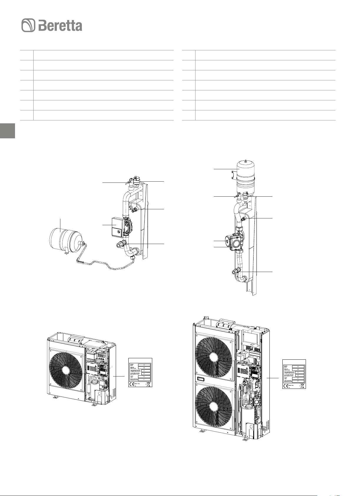
IDENTIFICATION
Technical Tag
The technical label shows all the appliance's technical and
performance data. If it gets lost, ask for a copy from the
BERETTA Technical Assistance Centre.
Tampering, removal, lack of identification labels or any-
thing else which does not permit the safe identification of
the product, makes any installation and maintenance operation difficult.
IDENTIFIKATION
Datapladen viser alle enhedens tekniske data samt ydeev-
ne. Denne label må ikke fjernes.
Hvis labelen mangler vanskeliggøres identifikation, instal-
lation og service af produktet.
Page 8
HYDRONIC UNIT LE
4 - 6 - 812 - 15
1 Automatic air vent valve
2 Temperature probe
3 Safety valve (output 1/2’)
4 Recirculation pump
5 Cap to release pump seizure
6 Flow meter
7 Expansion tank
8
7
1 Automatisk luftudlader
2 Temperatur føler
3 Sikkerhedsventil ½’
4 Cirkulationspumpe
5 Dæksel på pumpe
6 Flowmåler
7 Ekspansionsbeholder
7
6
4
1
6
2
1
2
3
5
4
4 - 6 - 8 12 - 15
3
Page 9
HYDRONIC UNIT LE
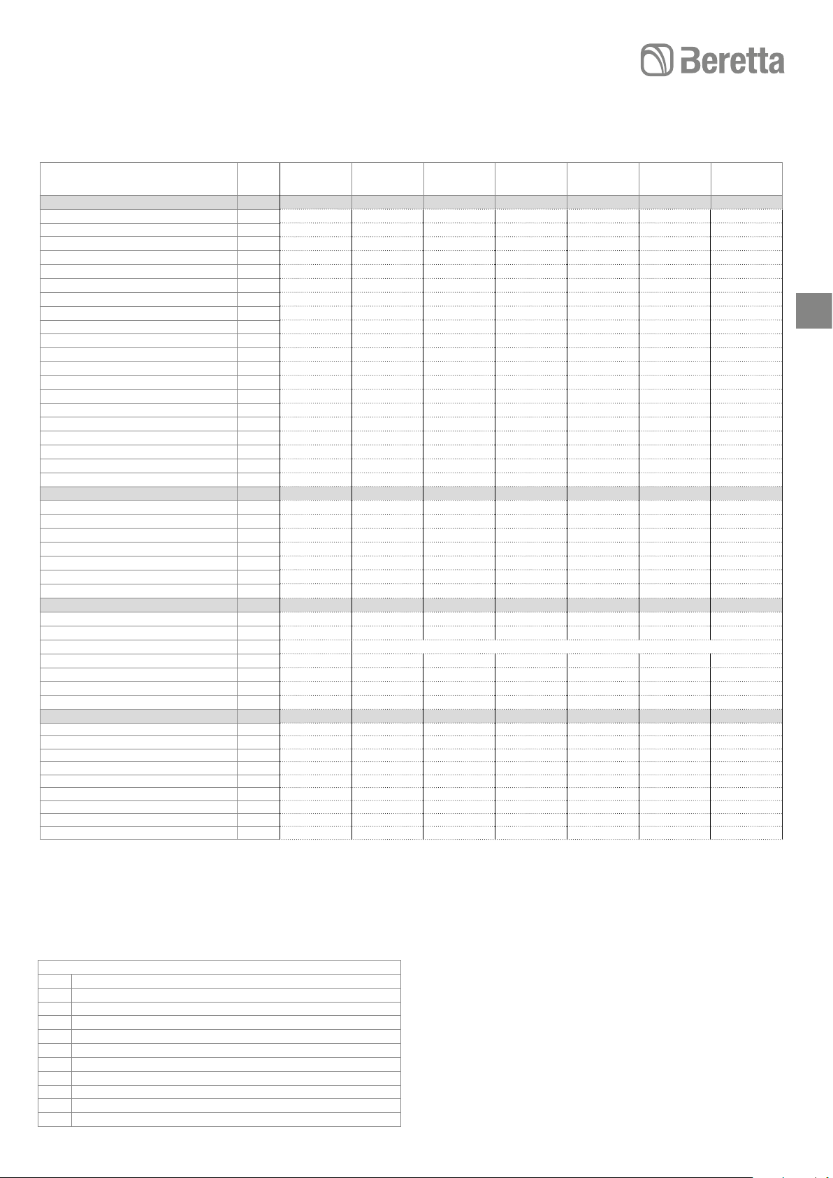
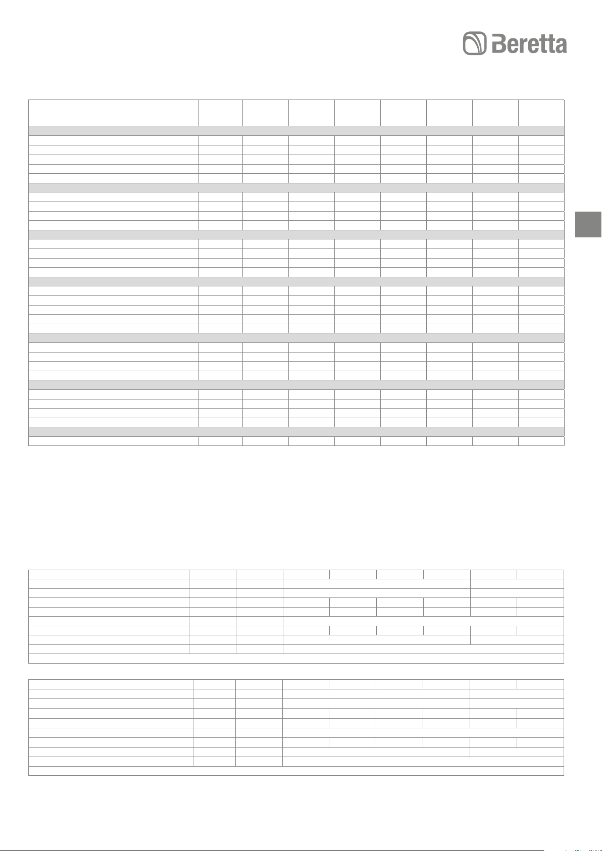
TECHNICAL DATA
Model
Performance in heating mode
Nominal capacity (1) kW
Power consumption (1) kW
COP (1)
Nominal capacity (2) kW
Power consumption (2) kW
COP (2)
Nominal capacity (3) kW
Power consumption (3) kW
COP (3)
Nominal capacity (4) kW
Power consumption (4) kW
COP (4)
Nominal capacity (5) kW
Power consumption (5) kW
COP (5)
Nominal capacity (6) kW
Power consumption (6) kW
COP (6)
Capacity (7)
COP (7)
Performance in cooling mode
Nominal capacity (8) kW
Power consumption (8) kW
EER (8)
Nominal capacity (9) kW
Power consumption (9) kW
EER (9)
ESEER (9)
Generalities
Sound pressure in heating mode dB(A)
Sound pressure in cooling mode dB(A)
Compressor
R410a refrigerant charge ** kg
Empty weight kg
Number of fans n 1 1 1 2 2 2 2
Fan diameter mm 495 495 495 495 495 495 495
Water circuit
Static pressure available kPa
Expansion tank capacity l
Expansion tank pre-charge kPa
System minimum water volume l
System maximum water volume * l
Machine water volume l
Maximum operating pressure kPa
Minimum filling pressure kPa
Hydraulic connections diameter Inches
kW
HYDRONIC
UNIT LE 4
4,07
0,98
4,15
3,87
1,19
3,26
3,5
1,13
3.1
3,4
1,31
2,6
4,1
1,51
2,71
4,27
1,46
2,92
1,06
2,75
4,93
1,17
4,2
3,33
1,10
3,02
4,36
42
44
ROTARY DC INV.
1,195
57
60
2
200
14
65
0,8
300
120
1M
HYDRONIC
UNIT LE 6
5,76 7,16 11,86 14,46 12 15
1,35 1,80 3,00 3,54 2,79 3,57
4,28 3,97 3,95 4,09 4,30 4,20
5,76 7,36 12,91 13,96 11,2 14,5
1,89 2,31 4,26 4,32 3,34 4,39
3,05 3,19 3,03 3,23 3,35 3,30
3,8 4,1 8 10,2 8,55 9,5
1,23 1,31 2,6 3,29 2,69 3,02
3.1 3.1 3.1 3.1 3,17 3,15
3,7 3,9 8 10,2 7,5 9,3
1,42 1,48 3,08 3,92 2,78 3,50
2,6 2,6 2,6 2,6 2,70 2,65
5,4 6,7 11,5 11,7 11,05 12
2,09 2,91 4,64 4,18 3,95 4,21
2,58 2,3 2,48 2,8 2,80 2,85
5,43 7,25 10,87 12,36 11,43 12,17
1,95 2,58 4,05 4,09 3,66 4,08
2,77 2,81 2,68 3,02 3,12 2,98
1,50 1,86 4,68 4,78 4,78 4,78
2,82 2,81 2,70 2,75 2,75 2,75
7,04 7,84 13,54 16,04 13,5 16
1,90 1,96 3,70 4,17 3,25 4,20
3,7 3,99 3,66 3,85 4,15 3,81
4,73 5,84 10,24 13,04 10,2 13
1,58 1,96 3,46 4,42 3,40 4,47
3 2,98 2,96 2,95 3 2,91
4,51 4,15 4,22 4,31 4,40 4,31
42 44 47 48 48 48
44 45 48 49 49 49
1,35 1,81 2,45 3,39 3,385 3,385
61 69 104 112 116 116
60 56 70 58 70 55
2 2 3 3 3 3
200 200 200 200 200 200
21 28 42 49 42 49
65 65 95 95 95 95
0,8 1,0 2,3 2,3 2,3 2,3
300 300 300 300 300 300
120 120 120 120 120 120
1M 1 M 1 M 1 M
HYDRONIC
UNIT LE 8
HYDRONIC
UNIT LE 12
TWIN ROTARY DC INVERTER
HYDRONIC
UNIT LE 15
HYDRONIC UNIT
LE 12 T
1M 1M
HYDRONIC
UNIT LE
* For greater water volumes it is necessary to provide an additional expansion tank
** The value of the refrigerant charge is indicative. The correct value is indicated on the technical data plate.
15 T
9
Reference conditions
Note / Note
1 outdoor temperature d.b. + 7 °C / w.b. + 6°C, water 35 - 30 °C.
2 outdoor temperature + 7 °C / w.b. + 6°C, water 45 - 40 °C.
3 outdoor temperature d.b. + 2 °C / w.b. +1°C, water 35 - 30 °C.
4 outdoor temperature d.b. + 2 °C / w.b. +1°C, water 45 - 40 °C.
5 outdoor temperature d.b. + 7 °C / w.b. + 6°C, water 55 °C.
6
outdoor temperature d.b. + 7 °C / d.b. + 6°C, water 47 - 55 °C.
7 outdoor temperature -7 °C, water 35 °C (with rated water flow)
8 outdoor temperature d.b. +35 °C / w.b. +24°C, water 18 - 23 °C.
9 outdoor temperature d.b. +35 °C, water 7 - 12 °C.
d.b. dry bulb
w.b. wet bulb
EN 14511
Sound pressure measured in a hemispheric field 4 metres
in front of the fan.
Unit performances have been provided in reference to
Directive UNI EN 14511:2011.
Fouling factor: 0.18 x 10⁻⁴ (m² K)/W.
Page 10
TEKNISKE DATA
HYDRONIC UNIT LE
Model
Varmefunktion
Nominel ydelse (1) kW
El forbrug (1) kW
COP (1)
Nominel ydelse (2) kW
El forbrug (2) kW
COP (2)
Nominel ydelse (3) kW
10
El forbrug (3) kW
COP (3)
Nominel ydelse (4) kW
Elforbrug (4) kW
COP (4)
Nominel ydelse (5) kW
Elforbrug (5) kW
COP (5)
Nominel ydelse (6) kW
El forbrug (6) kW
COP (6)
Kapacitet (7) kW
COP (7)
Kølefunktion
Nominel ydelse (8) kW
El forbrug (8) kW
EER (8)
Nominel ydelse (9) kW
El forbrug (9) kW
EER (9)
ESEER (9)
Generelt
Lydniveau i varmefunktion dB(A)
Lydniveau i kølefunktion dB(A)
Kompressor
R410a kølemiddel** kg
Netto vægt kg
Antal blæsere Stk 1 1 1 2 2 2 2
Blæser Diameter mm 495 495 495 495 495 495 495
Vandkredsløb
Statisk tilgængelig tryk kPa
Ekspansionsbeholder kapacitet l
Ekspansionsbeholder fortryk kPa
Min vandproduktion l
Max vandproduktion* l
UNIT vandindhold l
Max. arbejdstryk kPa
Min. arbejdstryk kPa
Rørforbindelser Zoll
HYDRONIC
UNIT LE 4
4,07
0,98
4,15
3,87
1,19
3,26
3,5
1,13
3.1
3,4
1,31
2,6
4,1
1,51
2,71
4,27
1,46
2,92
1,06
2,75
4,93
1,17
4,2
3,33
1,10
3,02
4,36
42
44
ROTARY DC INV.
1,195
57
60
2
200
14
65
0,8
300
120
1M
HYDRONIC
UNIT LE 6
5,76 7,16 11,86 14,46 12 15
1,35 1,80 3,00 3,54 2,79 3,57
4,28 3,97 3,95 4,09 4,30 4,20
5,76 7,36 12,91 13,96 11,2 14,5
1,89 2,31 4,26 4,32 3,34 4,39
3,05 3,19 3,03 3,23 3,35 3,30
3,8 4,1 8 10,2 8,55 9,5
1,23 1,31 2,6 3,29 2,69 3,02
3.1 3.1 3.1 3.1 3,17 3,15
3,7 3,9 8 10,2 7,5 9,3
1,42 1,48 3,08 3,92 2,78 3,50
2,6 2,6 2,6 2,6 2,70 2,65
5,4 6,7 11,5 11,7 11,05 12
2,09 2,91 4,64 4,18 3,95 4,21
2,58 2,3 2,48 2,8 2,80 2,85
5,43 7,25 10,87 12,36 11,43 12,17
1,95 2,58 4,05 4,09 3,66 4,08
2,77 2,81 2,68 3,02 3,12 2,98
1,50 1,86 4,68 4,78 4,78 4,78
2,82 2,81 2,70 2,75 2,75 2,75
7,04 7,84 13,54 16,04 13,5 16
1,90 1,96 3,70 4,17 3,25 4,20
3,7 3,99 3,66 3,85 4,15 3,81
4,73 5,84 10,24 13,04 10,2 13
1,58 1,96 3,46 4,42 3,40 4,47
3 2,98 2,96 2,95 3 2,91
4,51 4,15 4,22 4,31 4,40 4,31
42 44 47 48 48 48
44 45 48 49 49 49
1,35 1,81 2,45 3,39 3,385 3,385
61 69 104 112 116 116
60 56 70 58 70 55
2 2 3 3 3 3
200 200 200 200 200 200
21 28 42 49 42 49
65 65 95 95 95 95
0,8 1,0 2,3 2,3 2,3 2,3
300 300 300 300 300 300
120 120 120 120 120 120
1M 1 M 1 M 1 M 1M 1M
HYDRONIC
UNIT LE 8
HYDRONIC
UNIT LE 12
TWIN ROTARY DC INVERTER
HYDRONIC
UNIT LE 15
HYDRONIC UNIT
LE 12 T
* For større vandproduktion er det nødvendigt at tilslutte en ekstra ekspansionstank
** Værdien af kølemiddel er vejledende. Den korrekte værdi vises på datapladen.
HYDRONIC
UNIT LE
15 T
Standard forhold
1 Udetemperatur d.b. +7°C/w.b. +6°C, vand 35 – 30°C
2 Udetemperatur +7°C/w.b. +6°C, vand 45 – 40°C
3 Udetemperatur D.b. +2°C/w.b. +1°C, vand 35 – 30°C
4
Udetemperatur D.b. +2°C/w.b. +1°C, vand 45 – 40°C
5 Udetemperatur D.b. +7°C/w.b. +6°C, vand 55°C
6 Udetemperatur D.b. +35°C/w.b. 24°C, vand 18 – 23°C
7 Udetemperatur D.b. +35°C, vand 7 – 120°C
d.b.
Tør
w.b. Fugtig
Lydniveau målt i hemisfærisk område 4 meter fra blæser.
Funktioner i overensstemmelse med UNI EN 14511:2011.
Forureningsfaktor: 0,18 x 10⁻⁴ (m2K)/W.
Page 11
HYDRONIC UNIT LE
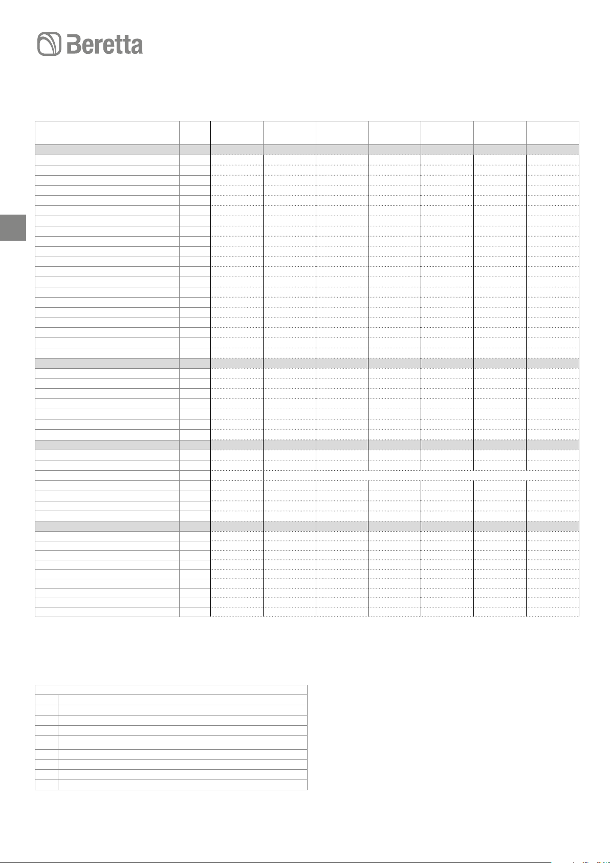
PERFORMANCE BASED ON THE CLIMATIC ZONE LEISTUNGSWERTE IN BEZUG AUF DIE KLIMAZONE
Model / Modell
Temperate zone - Average temperature (47 / 55 °C) - Tempereret zone - Gennemsnitstemperatur (47 / 55°C)
ŋs
SCOP 3,53 3,37 2,84 2,95 3,25 3,47 3,33
Pdesign kW 3,28 4,22 4,65 8,68 9,05 8,38 9,37
Annual consumption * / Årligt forbrug* kW/h 1.900 2.571 3.367 6.077 5.748 4.975 5.806
Energy class / Energi Klasse A++ A++ A+ A+ A++ A++ A++
Cold zone - Average temperature (47 / 55 °C) / Kold zone – gennemsnitstemperatur (47 / 55°C)
ŋs
SCOP 3,23 2,87 2,64 2,72 3,06 3,09 3,11
Pdesign kW 5,16 6,65 6,59 13,67 14,52 13,20 15,05
Annual consumption * / Årligt forbrug* kW/h 3.911 5.431 5.867 11.859 11.188 10.060 11.404
Warm zone - Average temperature (47 / 55 °C) / Varm zone – gennemsnitstemperatur (47 / 55°C)
ŋs
SCOP 4,82 4,60 3,88 4,03 4,44 4,74 4,55
Pdesign kW 3,10 3,79 4,83 8,04 8,38 7,76 8,67
Annual consumption * / Årligt forbrug* kW/h 843 1.085 1.649 2.651 2.508 2.177 2.537
Temperate zone - Low temperature (30 / 35 °C) /Tempereret zone – lavt temperatur 30 / 35°C)
ŋs
SCOP 3,73 3,60 3,03 3,19 3,61 3,78 3,68
Pdesign kW 3,83 4,92 4,56 10,00 10,75 9,76 11,12
Annual consumption * / Årligt forbrug* kW/h 2.015 2.806 3.088 6.467 6.137 5.314 6.230
Energy class / Energi Klasse A+ A+ A A+ A+ A+ A+
Cold zone - Low temperature (30 / 35 °C) / Kold zone – lav temperatur (30 / 35°C)
ŋs
SCOP 3,41 3,07 2,82 2,94 3,40 3,37 3,44
Pdesign 6,03 7,75 6,46 15,75 17,25 15,37 17,86
Annual consumption * / Årligt Forbrug kW/h 4.148 5.927 5.381 12.620 11.945 10.741 12.237
Warm zone - Low temperature (30 / 35 °C) / Varm zone – Lav temperatur (30 / 35°C)
ŋs
SCOP 5,09 4,92 4,14 4,36 4,93 5,16 5,03
Pdesign kW 3,42 4,06 5,09 9,20 9,96 9,04 10,29
Annual consumption * / Årligt forbrug* kW/h 880 1.084 1.624 2.809 2.681 2.327 2.714
Noise level / Lydniveau
Sound power / Lydniveau dB(A) 62 62 64 67 68 68 68
HYDRONIC
UNIT LE 4
138 132 111 115 127 136 130
126 112 103 106 119 121 122
190 181 152 158 175 187 179
146 141 118 125 141 148 144
133 120 110 115 133 132 135
201 194 163 171 194 203 198
HYDRONIC
UNIT LE 6
HYDRONIC
UNIT LE 8
HYDRONIC
UNIT LE 12
HYDRONIC
UNIT LE 15
HYDRONIC
UNIT LE
12 T
HYDRONIC
UNIT LE
15 T
* With backup electric heater * Med elektrisk varme backup
11
ELECTRICAL DATA ELEKTRISKE DATA
Modello
Power supply V- ph - Hz 230 - 1 -50 400 - 3 -50
Allowable voltage range V 207 ÷ 254 373 ÷ 424
Maximum power drawn kW 2 2,3 3,7 5,1 5,1 6,5 6,5
Maximum current drawn A 7,2 11 14 23 20 16 16
Type of fuses gL type
Power supply fuses current A 10- type B 16- type B 16- type B 25 - type D 25 - type D 16- type B 16- type B
Power supply cables mm
Maximum p
Use H03VV-F 4x0.75 mm² cables to connect the remote control to the wires
Model
El tilslutning V- PH - Hz 230 - 1 -50 400 - 3 -50
Volt V 207 ÷ 254 373 ÷ 424
Max. strøm input kW 2 2,3 3,7 5,1 5,1 6,5 6,5
Max. strømforbrug A 7,2 11 14 23 20 16 16
Sikringer Betriebsklasse gL
Sikringer el A 10 - Typ B 16 - Typ B 16 - Typ B 25 - Typ D 25 - Typ D 16 - Typ B 16 - Typ B
Elkabler mm
Max. ekstern. cirkulationspumpe A 2
Benyt H03W-F 4X0,75 mm2 kabler for at forbinde fjernbetjeningen til ledningerne
ump current external circulatio
n A 2
2
2
4 6 8 12 15 12T 15T
H07RN-F 3 x 2.5mm
4 6 8 12 15 12T 15T
H07RN-F 3 x 2.5mm
2
2
H07RN-F 5 x 2.5mm
H07RN-F 5 x 2.5mm
2
2
Page 12
HYDRONIC UNIT LE
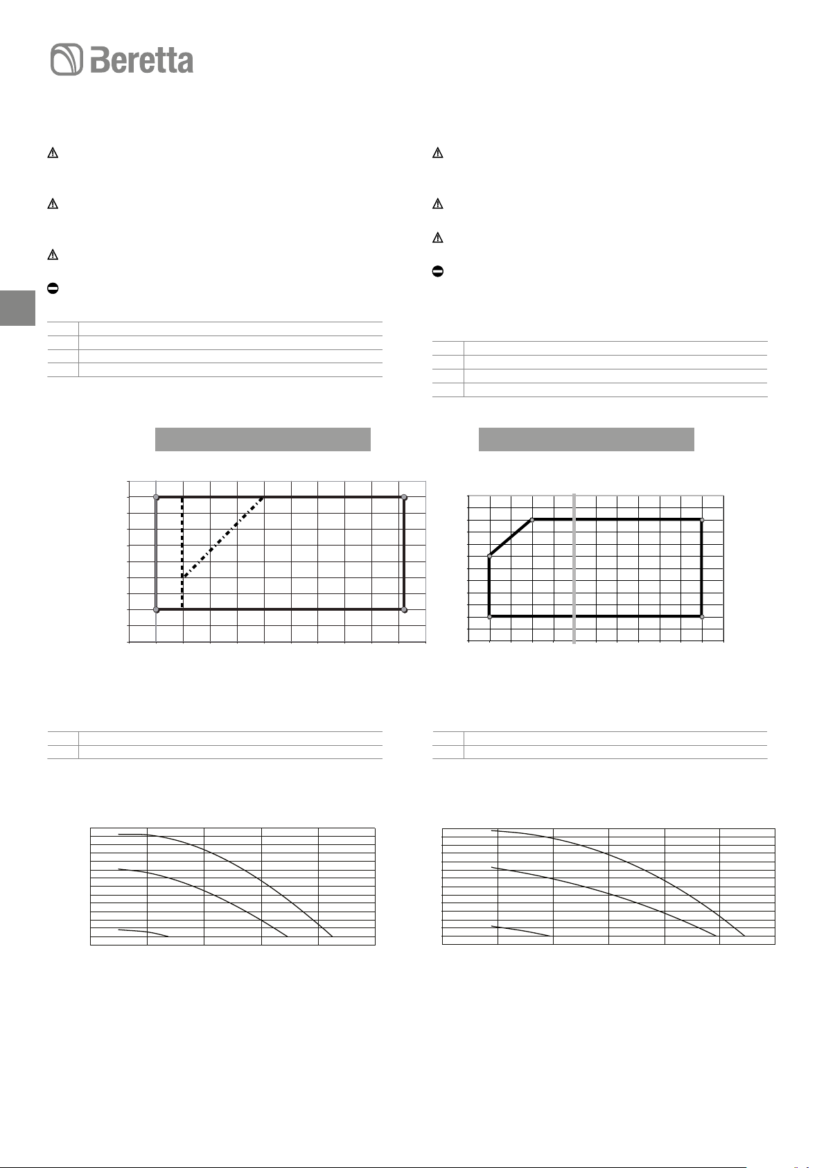
OPERATING CONDITIONS
Heat pump optimal operation when producing DHW
should have an outdoor air temperature that does not exceed 30°C.
For outdoor air temperatures exceeding 30°C the domes-
tic hot water production may be limited due to the intervention of machine safety devices.
For technical interventions, see the technical label on the
machine.
It is forbidden to work outside firing rate.
1212
1 Cooling
2 Heating
A Outdoor air temperature (°C)
B Output water temperature (°C)
20
18
16
14
12
10
B
8
6
4
2
0
-5 0510 15 20 25 30 35 40 45 50
006
004
DRIFT BETINGELSER
For optimal funktion af varmepumpen ved produktion af
varmt vand i sommerfunktion, må udetemperaturen ikke
overstige 30°C.
Hvis udetemperaturen overstiger 30°C er varmvandspro-
duktionen begrænset af apparatets sikkerhedsanordning.
For tekniske foranstaltninger henvises til datapladen på
produktet.
Indstillinger udenfor de angivne funktionsområder er ikke
tilladt.
1 Køling
2 Opvarmning
A Udetemperatur (°C)
B Fremløbstemperatur (°C)
1
70
65
60
55
50
B
45
40
35
008-012-015
A
30
25
20
15
10
-25-20 -15-10 -5 0510 15 20 25 30 35
2
A
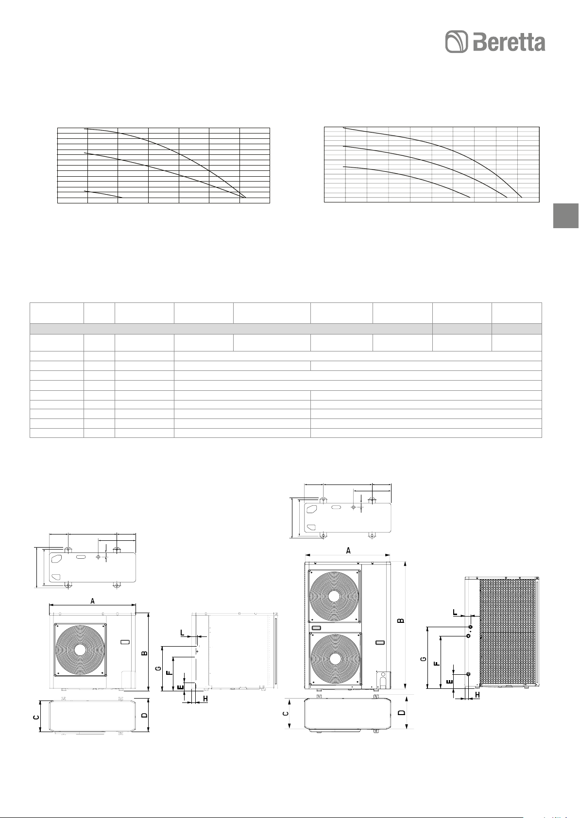
Flow rate-discharge head diagram
A Flow rate (l/s)
B Available static pressure (kPa)
4 6
75
65
55
45
B
35
25
15
5
0,10,0
0,2 0,3
A
0,4 0,5
Flowmåler
A Flow hastighed (I/s)
B Tilgængelig statisk tryk (kPa)
75
65
55
45
B
35
25
15
5
0,10,0
0,2 0,3
0,4 0,5 0,6
A
Page 13
HYDRONIC UNIT LE
41
1
2
3
41
1
2
3
75
65
55
45
B
35
25
15
5
0,10,0
0,2 0,3
8
0,4 0,5 0,6 0,7
A
95
85
75
65
B
55
45
35
25
15
0,10,0
0,2 0,3
0,4 0,5 0,6 0,7 0,8 0,9 1,0
OVERALL DIMENSIONS / DIMENSIONER
Model
Model
Overall dimensions / Dimensioner
Empty weight
Netto vægt
kg 57 61 69 104 112 116 116
A mm 908
B mm 821 1363
C mm 326
D mm 350
E mm 87 174
F mm 356 640
G mm 466 750
H mm 40 44
L mm 60 69
4 6 8 12 15 12 T 15 T
12 - 15
A
139
60015
363
400
54
430
37
400
363
60015
54
430
37
Page 14
HYDRONIC UNIT LE
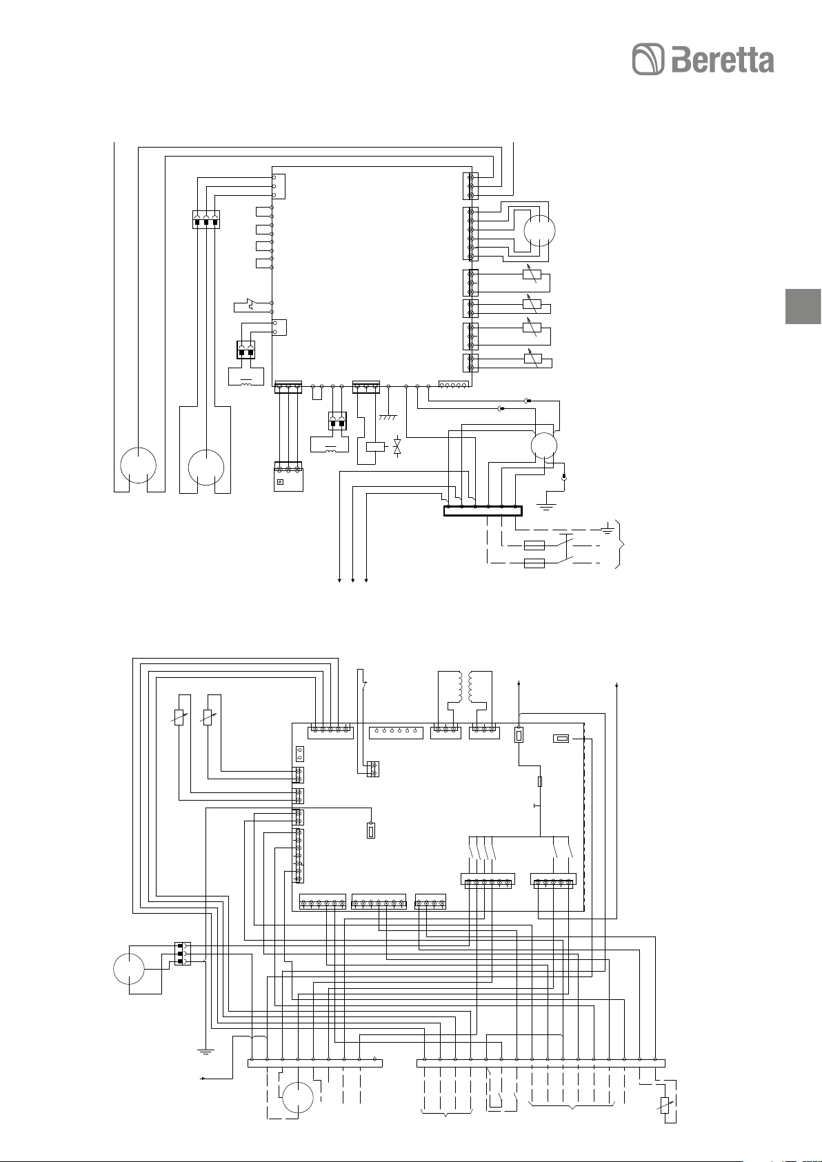
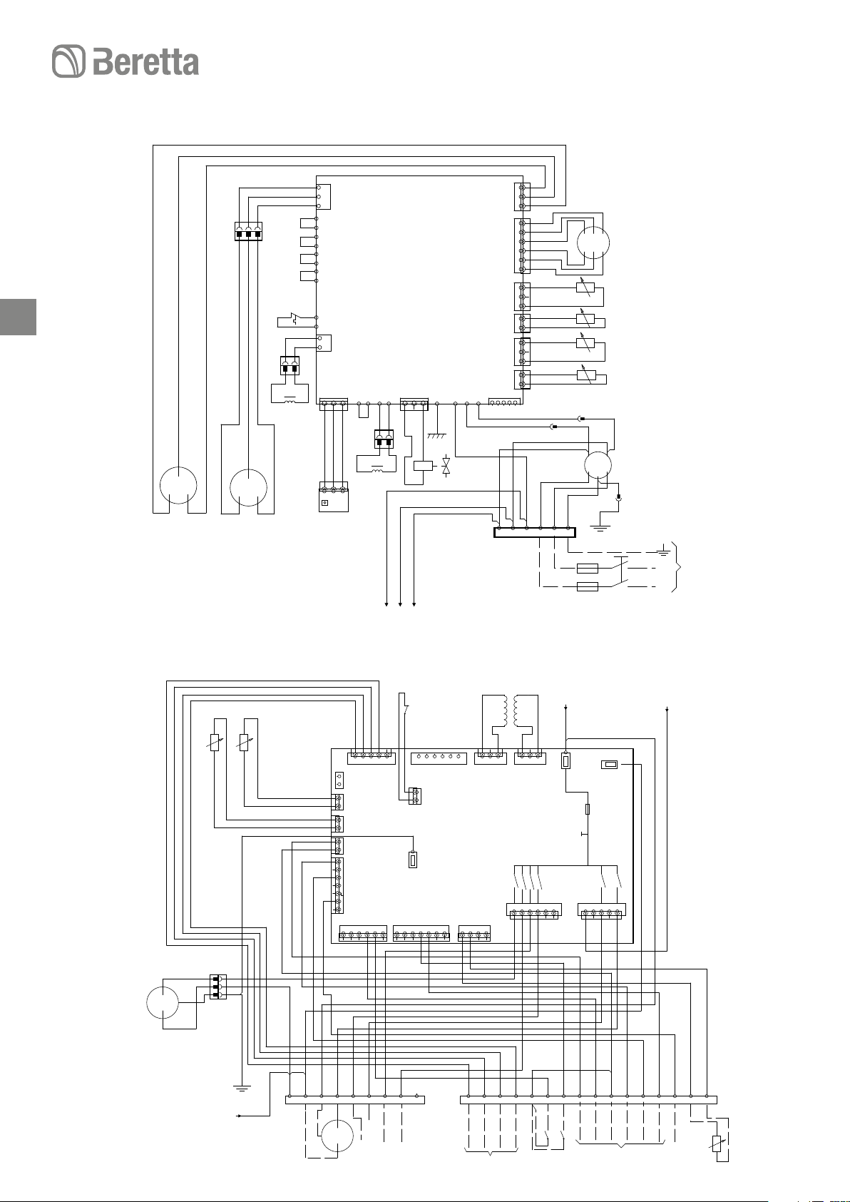
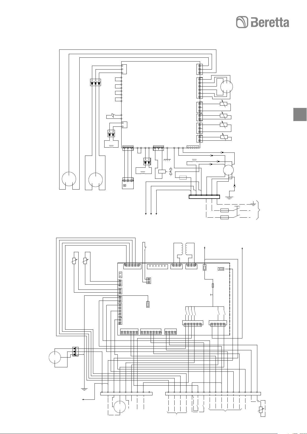
WIRING DIAGRAMS
- Wiring of the manufacturer
---- Wiring of the installer
CM Compressor motor
FM Fan motor
RV Reversing valve (4 way)
TS Temperature probe low pressure pipe
TO Temperature probe external unit
TD Temperature probe high pressure pipe
TE Temperature probe capacitor pipe
PMV Modulating valve motor
R Reactor
F Fuse
14
LWT Water outlet probe
EWT N.A.
TR Refrigerant sensor
FS Flow meter
TL Temperature probe capacitor pipe 2
C Compressor thermostat
H High pressure switch
RY Relay
T Transformer
PS Water pump motor
E-HTR Electric heater
AD Alarm status and defrost
OAT Outside air probe
LF Frequency Limiting
IS Domestic water input
SV Three-way domestic water valve
Y Yellow
O Orange
R Red
G Grey
A Brown
C Black
V Violet
B Blue
W White
Y/G Yellow Green
LEDNINGSDIAGRAM
- Fabriksmonteret
---- Monteret ved installation
CM Kompressor motor
FM Blæsermotor
RV Omskiftet ventil (4 vejs)
TS Temperaturføler lavtryksrør
TO Temperaturføler ekstern enhed
TD Temperaturføler højtryksrør
TE Temperaturføler kondensafløb
PMV Modulerende blæsermotor
R Reaktor
F Sikring
LWT Fremløbsføler
EWT Anvendes ikke
TR Føler afkøling
FS Flowmeter
TL Temperaturføler kondensafløb 2
C Kompressor termostat
H Højtryks kontakt
RY Relæ
Transformer
T Vandpumpemotor
PS El-varmeelement
E-HTR Alarm status og afrimning
AD Udeføler
OAT Frekvensgrænse
LF Brugsvands input
IS 3-vejs brugsvandsventil
SV Gul
Y Orange
O Rød
R Grå
G Brun
A Sort
C Violet
V Blå
B Hvid
W Gul/grøn
Y/G Gelb-grün
Page 15
HYDRONIC UNIT LE
HYDRONIC UNIT LE 4 POWER/HYDRONIC UNIT LE 4 FORBINDELSESDIAGRAM
CN300
CN700
CN503
CN502
CN501
CN500
1
C
1
3
2
1
1
6
6
5
4
3
2
1
1
3
2
1
1
2
1
1
3
2
1
1
2
1
1
W
N
3 L N PE
7CF
8CF
1PMV
9CF
10CF
11CF
12CF
1TS
1TO
1TD
1TE
15
W
W
C
1FL
U1 U3
L2 N4
Y/G
PE
Y/G
Y/G
N
230V1~50Hz
A
B
R
W
C
3
1 2
1CF
1 2 3
2CM
THERMOSTATFOR
C
W
R
COMPRESSOR
1T
2CF
3CM
W
C
S
1CM
C
R
R
1FM
P04
P05
P06
P25
Y
P24
P23
Y
P22
P21
A
P20
P35
Y
P34
12
P19
P18
P11
P08
2 1
2 1
CN805
1R
3CF
4CF
1
1 2 3
RWC
1 2
1
1MCC1530
P31
P332RP32
V
2 1
5CF
2 1
4CM
3
P30
CN701
6CF
1
1 2 3
1P.C.BOARD
F7 P03 P10 P02
C
1RV
CN806
C
O
1TB
B
C
A
L
/2.10/J4.1
/2.03/J3.1
/2.08/J1.1
HYDRONIC UNIT LE 4 CONTROL / HYDRONIC UNIT LE 4 FORBINDELSESDIAGRAM
1FS
J5.3
J5
J16.4
J16.5
J5.4
J5.5
J16.6
J20.7
7 6 5 4 3 2 1
21CF
1
2
J10.1
J10.2
J10.3
J10.4
J10.5 J10.6
1
J10
22CF
1
1
J17.1
J17
2
J17.2
1PCB
J15.1
J15
J20
1
J20.6
J20.5
1
J20.4
J20.3
J20.2
J20.1
J22.1 J22.2
1 2 3 4
23CF
1LWT
1TR
20CF
1 2 3 4 5
J5.1
J5.2
1
1
J6A.1
J6A
J6A.2
15CF
1
1
J6B.1
2
J6B
O
G
W
Y
Y/G
R
W
R
5CM
13CF
G
Y/G
1PS
2
2
3
3
1
1
A
B
J6B.2
16CF
1
1
J6B.1
2
J6C
J6B.2
17CF
1
1
J18.1
J18
2
J18.2
18CF
7
J11.7
6
J11.6
5
J11
J11.5
4
J11.4
3
J11.3
2
J11.2
1
J11.1
1
J16
1
G
J16.1
J16.2
J16.3
1 2 3 4 5 6
19CF
C
C
A
B
/1.05/J3.1
Y/G
B
B
O
R
G
ALARM+
DFR
/
HUMIDITY
C
EHTR
/
WP
EHS
/
DFR
3TB
N N 18 10 11 12 4 5 16
1SV
A
G
ALARM
2TB
2T
R
A
R
24CF
26CF
3
1 2
1 2
J13.1
J13.2
J13.3
J13
J22.4
1
J7
1
J7.1
1 2 3 4 5 6
25CF
J2.1
J7.2
1
J22
J22.3
J1.1//1.05
B
A
3
J1.1
J1
J2.2
J2.3
J2
J7.3
J7.4 J7.5 J7.6
C
W
C W G Y 13 14 15 7 6 3 2 1 8 21 23 24
1
1
2
2
1LF
REMOTE
1IS
J4
1
27CF
J4.1 J4.2
J4.3 J4.4
1 2 3 4 5
J3
REMOTE
CONTROL
J4.1//1.05
C
J4.5
A
C
O
1OAT
ALARM
INPUT
Page 16
HYDRONIC UNIT LE
HUMIDITY
HYDRONIC UNIT LE 6 Power / HYDRONIC UNIT LE 6 FORBINDELSESDIAGRAM
16
CN300
CN700
CN503
CN502
CN501
CN500
1
C
1
3
2
1
1
6
6
5
4
3
2
1
1
3
2
1
1
2
1
1
3
2
1
1
2
1
1
W
N
3 L N PE
7CF
8CF
1PMV
9CF
10CF
11CF
12CF
1TS
1TO
1TD
1TE
W
W
C
1FL
U1 U3
L2 N4
Y/G
PE
Y/G
Y/G
N
230V1~50Hz
A
B
R
W
C
3
1 2
1CF
1 2 3
2CM
THERMOSTATFOR
C
W
R
COMPRESSOR
1T
2CF
3CM
W
C
S
1CM
C
R
R
1FM
P04
P05
P06
P25
Y
P24
P23
Y
P22
P21
A
P20
P35
Y
P34
12
P19
P18
P11
P08
2 1
2 1
CN805
1R
3CF
4CF
1
1 2 3
RWC
1 2
1
1MCC1530
P31
P332RP32
V
2 1
5CF
2 1
4CM
3
1P.C.BOARD
CN701
1
P30
F7 P03 P10 P02
1 2 3
6CF
C
1RV
CN806
C
O
1TB
B
C
A
L
/2.10/J4.1
/2.03/J3.1
/2.08/J1.1
HYDRONIC UNIT LE 6 CONTROL / HYDRONIC UNIT LE 6 FORBINDELSESDIAGRAM
1FS
J5.2
J16.4
J5.3
J5
J16.5
J5.4
J5.5
J16.6
J20.7
7 6 5 4 3 2 1
21CF
1
2
J10.1
J10.2
J10.3
J10.4
J10.5 J10.6
1
J10
22CF
1
1
J17.1
J17
2
J17.2
1PCB
J15.1
J15
J20
1
J20.6
J20.5
1
J20.4
J20.3
J20.2
J20.1
J22.1 J22.2
23CF
1LWT
1TR
20CF
1 2 3 4 5
J5.1
1
1
J6A.1
J6A
J6A.2
15CF
1
1
J6B.1
2
J6B
O
G
W
Y
Y/G
R
W
R
5CM
13CF
1
1
G
2
2
3
3
Y/G
1PS
A
B
J6B.2
16CF
1
1
J6B.1
2
J6C
J6B.2
17CF
1
1
J18.1
J18
2
J18.2
18CF
7
J11.7
6
J11.6
5
J11
J11.5
4
J11.4
3
J11.3
2
J11.2
1
J11.1
1
J16
1
G
J16.1
J16.2
J16.3
1 2 3 4 5 6
19CF
C
C
A
B
/1.05/J3.1
Y/G
B
B
O
R
G
3TB
N N 18 10 11 12 4 5 16
1SV
C
EHTR
/
WP
ALARM+
EHS
DFR
/
/
DFR
A
G
ALARM
2TB
2T
B
R
A
R
24CF
26CF
3
J13.3
J7
1
25CF
3
1 2
J2.1
J2.2
J2.3
1
J2
J7.1
J7.2
J7.3
J7.4 J7.5 J7.6
1 2 3 4 5 6
1
J22
J22.3
1 2 3 4
1 2
J13.1
J13.2
J13
J22.4
W
C W G Y 13 14 15 7 6 3 2 1 8 21 23 24
REMOTE
1LF
J1.1//1.05
J4.1//1.05
A
J1.1
J1
J3
C
J4
1
J4.1 J4.2
J4.3 J4.4
J4.5
1 2 3 4 5
27CF
A
C
ALARM
INPUT
O
1OAT
C
1
1
2
2
1IS
REMOTE
CONTROL
Page 17
HYDRONIC UNIT LE
HUMIDITY
HYDRONIC UNIT LE 8 POWER / HYDRONIC UNIT LE 8 FORBINDELSESDIAGRAM
R
W
C
3
1 2
40CF
1 2 3
7CM
THERMOSTATFOR
W
6CM
R
S
COMPRESSOR
C
2T
41CF
8CM
C
C
W
R
R
1FM
2 1
2 1
P04
P05
P06
P25
Y
P24
P23
Y
P22
P21
A
P20
P35
Y
P34
12
P19
P18
P11
P08
1P.C.BOARD
CN300
CN700
CN503
CN502
CN501
1
6
1
1
1
1
CN500
CN805
1R
1
1 2 3
42CF
RWC
3
1 2
43CF
1
1MCC1530
P33 P32
V
CN701
1
P31 P30
45CF
2 1
44CF
2 1
9CM
2R
1 2 3
1RV
F7 P03
C
P10 P02
C
O
1 2
C
B
A
/2.10/J4.1
/2.03/J3.1
/2.08/J1.1
1
CN806
1
W
3R
R
1F
R
1TB
N
1
HYDRONIC UNIT LE 8 CONTROL / HYDRONIC UNIT LE 8 FORBINDELSESDIAGRAM
1FS
J5.3
J5
J16.4
12
EHTR
/
WP
J5.4
J5.5
J16.5
J16.6
60CF
C
4
EHS
/
DFR
1
2
J10.1
J10.2
1
61CF
1
1
J17.1
J17
2
J17.2
J15.1
J15
J20
J20.7
J20.6
J20.5
J20.4
J20.3
7 6 5 4 3 2 1
A
G
5
16
ALARM
J10.3
J10.4
J10.5 J10.6
J10
1PCB
1
1
J20.2
J20.1
J22.1CJ22.2
1 2 3 4
62CF
3TB
1LWT
1TR
59CF
1 2 3 4 5
J5.1
J5.2
1
1
J6A.1
J6A
J6A.2
54CF
1
1
J6B.1
2
J6B
O W
G
Y
Y/G
R
W
R
10CM
52CF
1
1
G
1PS
2
2
3
3
Y/G
B
B
Y/G
2TB
N N 18
B
/1.05/J3.1
J6B.2
55CF
1
1
J6B.1
2
J6C
J6B.2
56CF
1
1
J18.1
J18
2
J18.2
57CF
7
J11.7
6
J11.6
5
J11
J11.5
4
J11.4
3
J11.3
2
J11.2
1
J11.1
1
J16
1
J16.1
J16.2
C
1 2 3 4 5 6
58CF
J16.3
C
A
G
B
A
G
O
R
10
11
1SV
ALARM+
DFR
/
3T
R
3
J13.3
A
65CF
1 2
1
J7
1
J7.1
1 2 3 4 5 6
64CF
B
3
J2.1
J2.2
J2.3
J2
J7.2
J7.3
J7.4 J7.5
R
63CF
1 2
J13.1
J13.2
1
J13
J22
J22.3
J22.4
W
W
G
Y
13
REMOTE
46CF
3
2
1
47CF
6
5
4
3
2
1
48CF
3
2
1
49CF
2
1
50CF
3
2
1
51CF
2
1
W
3 L N PE
J1.1//1.05
A
J1.1
J1
J7.6
C
14
15
1
1
2
2
1LF
1IS
A
B
J4
1
66CF
7
C
1FL
Y/G
J4.1 J4.26J4.3
1 2 3 4 5
1PMV
C
J3
J4.43J4.5
REMOTE
CONTROL
W
W
U1 U3
L2 N4
PE
Y/G
2 1 8
1TS
1TO
1TD
1TE
Y/G
A
J4.1//1.05
C
21 23 24
ALARM
INPUT
17
N
L
230V1~50Hz
O
C
1OAT
Page 18
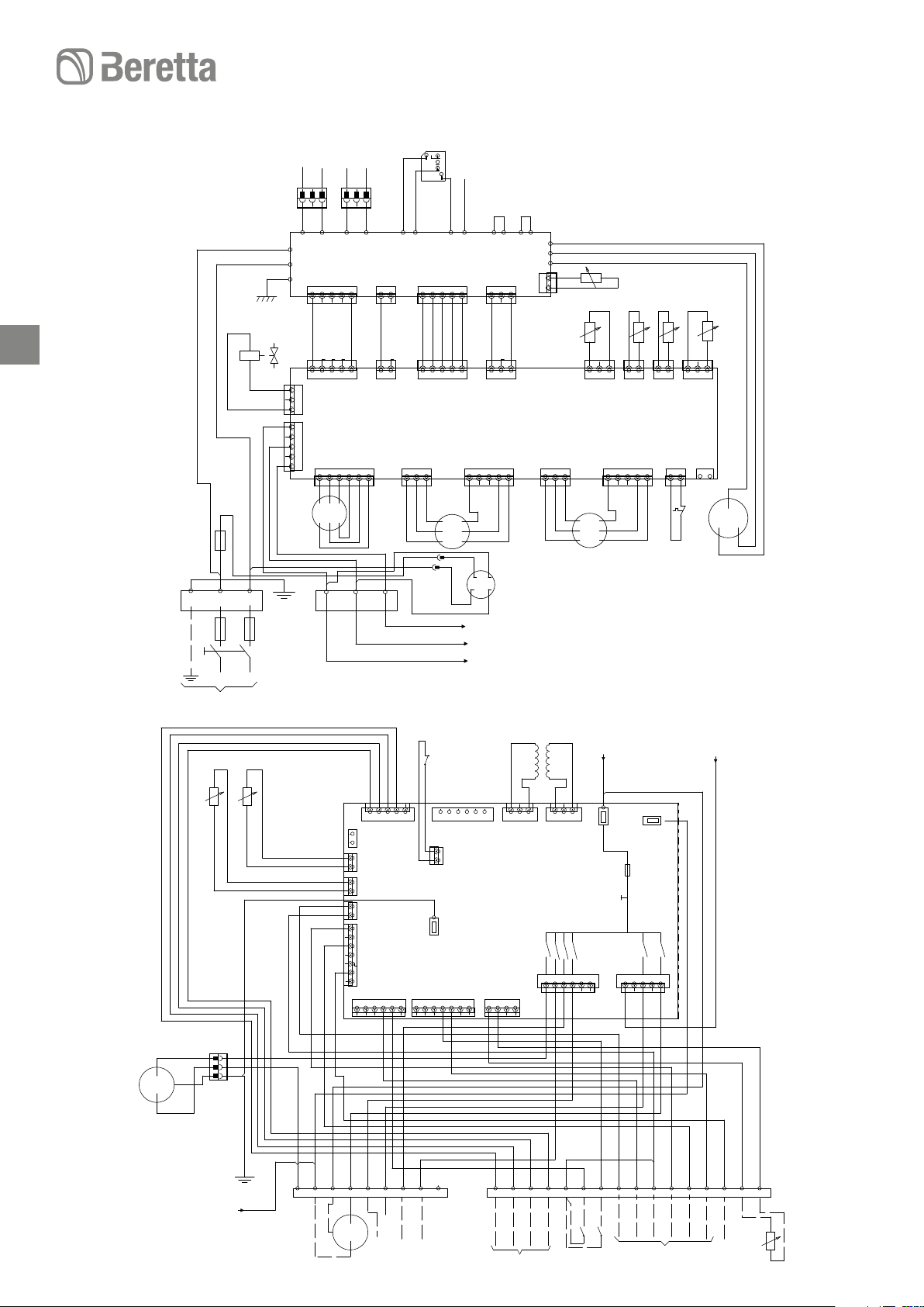
HYDRONIC UNIT LE 12 POWER/HYDRONIC UNIT LE 12 FORBINDELSESDIAGRAM
R
W
C
Y/G
WRW
GCG
O
O
A
PRB
C
W
C
YYB
B
O
O
C
W
R
W
W
C
C
A
R
R
B
1TB
PE
230V1~50Hz
1F
1
2
L
L
1RV
N
N
1CF
1
2
3
2CF
1
2
3
4
5
CN01
CN02
CN03
1P.C.BOARD
2P.C.BOARD
1CM
1 2 3
3CF
1 2 3
P08
1
CN700
1
CN02
4CF
1 2 3 4 5
5CF
1 2 3 4 5
1
1
1PVM
6CF
1 2 3 4 5 6
2TB
1
P09
1
R
CN13
CN01
CN702
2CM
1 2 3
7CF
1 2 3
P12NP13
R
1
8CF
1 2
9CF
1 2
1
CN05
CN04
3
P21
10CF
1 2 3
1
CN303
P24
1
11CF
1 2 3 4 5
12CF
1 2 3 4 5
1
+
1FM
CN800
CN06
P28
J4.1//2.10
J3.1//2.03
J1.1//2.08
P29
13CF
1 2 3 4 5
ED
1
CN302
1
14CF
1 2 3
15CF
1 2
3
1
P19
CN04
CN03
P20 P17 P18
CN600
1
16CF
1 2 3
1
17CF
1
2
CN09
CN10
CN11
CN301
2FM
1TH
1TD
18CF
1 2
3
1
CN600
19CF
1 2 3 4 5
1
CN300
20CF
1 2
1
1TS
CN605
21CF
1 2
1
1TE
CN604
22CF
1 2
THERMOSTAT
FORCOMPRESSOR
1
CN500
1T
1
2
23CF
1 2
3
1
CN601
1TO
1
CN606
3CM
R
C
S
132
4
1FL
18
HYDRONIC UNIT LE
HYDRONIC UNIT LE 12 CONTROL / HYDRONIC UNIT LEE 12 FORBINDELSESDIAGRAM
1FS
J5.3
J5
J16.4
J16.5
12
EHTR
/
WP
J5.4
J5.5
J16.6
J20.7
7 6 5 4 3 2 1
32CF
A
C
G
4
5
EHS
ALARM
/
DFR
J15
J20.6
1
2
33CF
1
1
2
J15.1
J20
J20.5
16
J10.1
J10.2
J10.3
J10
1
J17.1
J17
J17.2
J20.4
J20.3
J20.2
J10.4
1
J20.1
1PCB
J10.5 J10.6
1
J22.1CJ22.2
34CF
4TB
1LWT
O
W
1PS
G
G
Y/G
B
Y
4CM
1
2
3
/1.05/J3.1
1TR
Y/G
24CF
1
2
3
Y/G
B
W
A
3TB
R
B
N N 18
R
G
C
B
26CF
1
2
27CF
1
2
28CF
1
2
29CF
7
6
5
4
3
2
1
1
30CF
R
10
1SV
31CF
1 2 3 4 5
J5.1
J5.2
1
1
J6A.1
J6A
J6A.2
1
J6B.1
J6B
J6B.2
1
J6B.1
J6C
J6B.2
1
J18.1
J18
J18.2
J11.7
J11.6
J11
J11.5
J11.4
J11.3
J11.2
J11.1
1
J16
J16.1
J16.2
J16.3
1 2 3 4 5 6
C
A
O
G
11
ALARM+
DFR
/
HUMIDITY
R
35CF
1
J22
J22.3
1 2 3 4
1 2
J13.1
W
REMOTE
J22.4
J13
R
3
J13.2
J13.3
G
2T
37CF
1
J7
1
36CF
A
1 2
J2.1
J2.2
J2
J7.1
J7.2
J7.3
1 2 3 4 5 6
Y
13
J1.1//1.05
B
A
3
J1.1
J1
J2.3
J3
J4.1//1.05
C
J4
1
J7.4 J7.5
J7.6
J4.1 J4.26J4.3
J4.43J4.5
1 2 3 4 5
38CF
A
C
C
O
W
14
15
7
1
1
2
2
1LF
1IS
REMOTE
CONTROL
2 1 8
21 23 24
ALARM
INPUT
1OAT
Page 19

HYDRONIC UNIT LE
HYDRONIC UNIT LE 15 POWER/HYDRONIC UNIT LE 15 FORBINDELSESDIAGRAM
1R 2R
1CM
1 2
1 2
P05
CONTROLP.C.BOARD
MCC1571
CN701
(WHITE)
1 2 3 4
1 2
11CM
1 2
64CF
P06
P07
CN04
(WHITE)
1 2 3 4 5 6
74CF
10CM
63CF
65CF
1
CN400
1FM
2FM
49C
12
1TL
1TE
2
(WHITE)
CN300
(WHITE)
CN609
(BLUE)
CN610
(YELLOW)
CN604
(WHITE)
CN603
(WHITE)
CN602
(YELLOW)
CN601
(WHITE)
CN600
(WHITE)
72CF
1PCB
SW804
432143214321
ONONON
SW803
SW802
CN710
(WHITE)
1 2 3 4 5 6
SW801
CN704
(BLUE)
3
75CF
1
2
3
66CF
1
2
67CF
1
2
68CF
1TD
1
2
3
69CF
1TO
1
2
70CF
1
2
71CF
1TS
1
2
3
P04
SW800
RY704
73CF
G
1RV
1PMV
R
W
2TB
1 2 3
A
R
W
U V W
CN200
CN201
F01
T25A,250V~
F03
T10A,250V~
P01
C
J4.1//2.10
B
J3.1//2.03
J1.1//2.08
C
CN202
L/F
C
P09
P02
R
1TB
W
L N
N
L
19
230V1~50Hz
HYDRONIC UNIT LE
1LWT
O
G
W
Y
12CM
G
Y/G
1PS
B
/1.07/J3.1
15 CONTROL/HYDRONIC UNIT LE 15 FORBINDELSESDIAGRAM
1FS
J5.3
J5.4
J5
J16.5
J5.5
J16.6
J20.7
7 6 5 4 3 2 1
84CF
A
C
G
4
1
2
J10.1
J10.2
J10.3
J10.4
1
85CF
1
2
J15.1
J15
J20.6
J20.5
5
J10.5 J10.6
J10
1
J17.1
J17
J17.2
2PCB
J20
1
J20.4
16
1
J20.3
J20.2
J20.1
J22.1CJ22.2
1 2 3 4
86CF
4TB
1TR
83CF
1 2 3 4 5
J5.1
J5.2
1
1
J6A.1
J6A
J6A.2
78CF
1
1
J6B.1
2
J6B
J6B.2
79CF
1
1
J6B.1
2
J6C
J6B.2
80CF
1
1
J18.1
J18
2
J18.2
81CF
7
J11.7
6
J11.6
5
J11
Y/G
R
W
R
76CF
1
1
2
2
3
3
A
B
Y/G
3TB
N N 18
B
J11.5
4
J11.4
3
J11.3
2
J11.2
1
J11.1
1
J16
1
G
J16.1
J16.2
J16.3
J16.4
1 2 3 4 5 6
82CF
C
C
A
O
R
G
10
11
12
B
EHTR
/
1SV
WP
ALARM+
EHS
DFR
/
HUMIDITY
ALARM
/
DFR
1T
B
R
A
R
87CF
1
J22
1 2
J22.3
REMOTE
89CF
3
J13.1
J13.2
J13.3
J13
J22.4
W
G
1 2
J2.1
1
J7
1
J7.1
J7.2
1 2 3 4 5 6
88CF
Y
3
J2.2
J2.3
J2
J7.3
J7.4 J7.5
13
J1.1//1.07
J4.1//1.07
A
J1.1
J1
J3
C
J4
1
J7.6
J4.1 J4.26J4.3
J4.43J4.5
1 2 3 4 5
90CF
A
C
C
O
W
14
15
7
1
1
2
2
1LF
1IS
REMOTE
CONTROL
2 1 8
21 23 24
ALARM
INPUT
1OAT
Page 20

HYDRONIC UNIT LE
HUMIDITY
HYDRONIC UNIT LE 12 T/15T Power / Hydronic Unit LE 12 T/15 T Forbindelsesdiagram
POSISTER
1RY
A
3
1
1 2 3 4 5 6
J10.1
J10.2
1
J17.1
J17
J17.2
J20
J20.4
J20.3
CN610
YEL
OPTION
J10.3
R
R
C
15CF
1
1
2
CN02
3
RED
16CF
1
1
2
CN708
3
BLU
1
1
2
CN700
YEL
3
17CF
18CF
1
1
2
CN704
3
BLU
19CF
6
5
4
CN710
3
WHI
2
1
1
14CF
20CF
1
Y
1
CN101
2
WHI
3
B
CN04
CN11
CN12
CN13
20SF
OPTION
1PMV
1T
B
R
40CF
J10.4
J10.5 J10.6
1
J10
42CF
3
1 2
J13.1
J13.2
J13.3
J13
3
1 2
J2.1
J2.2
J2.3
1
J2
A
R
1PCB
J7
1
J7.1
J7.2
J7.3
J7.4 J7.5
J22
1
1
J20.2
J20.1
J22.1CJ22.2
1 2 3 4
39CF
1 2 3 4 5 6
41CF
J22.3
J22.4
W
4TB
W
G
Y
13
REMOTE
R
W
C
G
CN05
CN06
CN07
W
CN20
CN08
CN09
A
3CF
CN50
WHI
1P.C.BOARD
MCC1600
NOISEFILTER
1 2
CN10
CN16
CN17
C
CN18
CN19
8CF
1
1
2
CN23
3
RED
4
CN51
5
BLK
5CF
1 2
R
R
R
W
G
R
G
A
R
R
C
63H
49C
1 2
20
1 2 3 4 5
4CF
(CH56)
1R
G
W
R
1F
10A
250V
R
W
1
2
G
6CF
1
1
CN608
WHI
1CF
1
1
2
CN01
3
WHI
4
5
1 2
1 2
11CF
12CF
1
2P.C.BOARD
MCC1599
CDB
1
CN609
CN690
BLU
GRN
CN802
WHI
R
R
2R
U
W
1TB
PE
L1
L1
L2L2L3
400V3N~50Hz
CN600
CN601
WHI
2TB
1
2
L3
N
N
A
/2.08/J1.1
B
/2.03/J3.1
3
C
/2.10/J4.1
WHI
1
1
1 2 3
1 2
2CF
7CF
1TS
1TE
CN603
CN602
YEL
1
1 2
9CF
1TO
CN604
WHI
WHI
1
1
1 2 3
1 2
10CF
13CF
1TD
1TL
HYDRONIC UNIT LE 12 T/15T Control / Hydronic Unit LE 12 T/15 T Forbindelsesdiagram
1FS
J5.3
J5.4
J5
J16.5
C
EHS
/
DFR
1
2
J5.5
J15
J16.6
J20.7
J20.6
7 6 5 4 3 2 1
37CF
A
G
4
5
ALARM
1
38CF
1
2
J15.1
J20.5
16
1PS
1LWT
O
G
W
Y
G
Y/G
B
2CM
29CF
1
2
3
/1.03/J3.1
1TR
36CF
1 2 3 4 5
J5.1
J5.2
1
30CF
1
1
J6A.1
2
J6A
J6A.2
31CF
1
1
J6B.1
2
J6B
J6B.2
32CF
1
1
J6B.1
2
J6C
J6B.2
33CF
1
1
J18.1
J18
2
J18.2
34CF
7
J11.7
6
J11.6
5
J11
Y/G
R
W
R
J11.5
4
J11.4
3
J11.3
2
J11.2
1
J11.1
1
J16
1
G
J16.1
J16.2
J16.3
J16.4
1 2 3 4 5 6
35CF
C
C
1
2
3
Y/G
A
3TB
B
B
N N 18
A
O
R
G
10
11
12
B
EHTR
/
1SV
WP
ALARM+
DFR
/
21CF 1 2 3 4 5
1IPDUBOARD
MCC1596
COMPRESSOR
CN19
Y
(CH68)
3R
J1
J7.6
C
14
1
2
1LF
1
CN20
Y
C
V
O
J1.1//1.03
A
J1.1
15
1
2
1IS
CN851
RED
22CF
23CF
24CF
1
43CF
CN211
CN212
CN213
(CH78)
4R
1
1
CN502
2
WHI
3
1
1
CN602
2
BLK
1
1
2
3
CN500
4
RED
5
6
7
25CF
R
J4
J4.1 J4.26J4.3
1 2 3 4 5
7
U
V
W
W
1CM
C
26CF 1 2 3 4 5
1
CN504
BLU
CN750
WHI
1
1 2 3
W
1FM
C
J3
J4.43J4.5
REMOTE
CONTROL
R
1
2IPDUBOARD
MCC1597
FAN
CN700
BLU
1
27CF
1 2 3
W
2FM
R
2 1 8
CN505
RED
A
28CF1 2 3 4 5
P501
C
J4.1//1.04
C
21 23 24
ALARM
INPUT
C
C
O
1OAT
Page 21

HYDRONIC UNIT LE
REFRIGERATING CIRCUIT DIAGRAM / KØLE KREDSLØBS DIAGRAM
LWT sensor
LWT føler
Plate heat exchanger / Pladeveksler
Electronic expansion valve
Elektronisk tryksensor
EWT sensor
EWT føler
TR føler
TR sensor
Distributor
21
Fordeler
TE sensor
TO sensor / TO føler
Silencer
Fordamper
4-way valve
TE føler
Veksler
Heat exchanger
Silencer / Fordamper
4-vejs ventil
TS sensor / TS føler
TD sensor / TD føler
Påfyldnings-studs
Charge connection
Rotary compressor
Kompressor
Trykbeholder
Fluid receiver
Page 22

HYDRONIC UNIT LE
600154154
430
400
363
37
1
2
3
INSTALLER
PRODUCT DELIVERY
Preliminary instructions
We recommend the packaging only be removed when the
appliance has been placed at the installation point.
Carefully remove any adhesive strips on the appliance.
Do not dispose of, abandon or leave potentially hazardous
packing material within the reach of children.
22
Composition of the supply
The following are supplied:
Installer's instruction booklet
Warranty certificate
Bar code labels
Control panel
Fair leads (only models 15 - 12/15T)
Condensate discharge pipe
The supplied accessories are inside the electrical panel
HANDLING AND TRANSPORT
Handling should be carried out by suitably equipped qual-
ified personnel, and with equipment appropriate for the
weight of the appliance in compliance with accident pre-
vention regulations.
When being moved, the unit should always be kept in a
vertical position.
The weight of the appliance is out of balance towards the
compressor side.
To lift the unit use pipes with a suitable diameter and thick-
ness for the weight of the appliance.
INSTALLATØR
LEVERING AF PRODUKTET
Foreløbige instruktioner
Placer produktet ved installationsstedet før udpakning.
Fjern omhyggeligt alle strips fra produktet.
Efterlad ikke potentielt farligt indpakningsmaterialer/em-
ballage i børns nærhed.
Indhold
Installations manual
Garanti bevis
Stregkode label
Kontrolpanel
Ledningsholdere (Kun model 15 – 12/15T)
Kondens afløbsrør
-De medfølgende dele er placeret ved el-panelet.
HÅNDTERING OG TRANSPORT
Varmepumpen skal håndteres af uddannede teknikere.
Varmepumpen skal altid håndteres i opret position.
Vægtfordelingen er tungest ved kompressoren.
For at løfte produktet bruges dertil egnede redskaber.
ADGANG TIL INDRE DELE
- Fastgørelsesskruerne løsnes.
- Fjern frontlågen.
ACCESS TO INNER PARTS
- Loosen the fixing screws
- Remove the access panel.
Page 23

HYDRONIC UNIT LE
INSTALLATION
Preliminary instructions
The installation position should be decided by the system
designer or by an expert and should take into account technical requirements and current standards and legislation.
You should avoid:
Positioning in ducts and/or hopper windows.
Obstacles or barriers that cause the recirculation of the
expelled air.
Places with aggressive atmospheres.
Small places where the appliance sound level could be
magnified by reverberations or resonance.
Placement in corners where dust, leaves and other debris
could deposit reducing the efficiency of the appliance by
obstructing the flow of air.
That the air expelled from the appliance enters inhabited
rooms through doors or windows, causing discomfort for
the persons present.
That the air expelled from the unit is met by a head wind.
The units must:
Be positioned on a levelled surface capable of supporting
the weight.
Be positioned on a sufficiently rigid floor slab that does not
transfer vibrations to adjacent or underlying rooms.
It is suggested that a rubber plate be placed between the
unit and the floor or that antivibration supports suitable for
the weight of the unit be used.
The unit must only be installed outdoors.
If several units are placed side by side on the battery side
it is necessary to add up the minimum safety distances.
Provide for lifting the unit off the floor:
20 mm without conveying the condensation dis-
charge
90 - 100 mm to permit the conveyance of the con-
densation discharge
If the unit is installed in areas subject to heavy snowfall,
install at a height at least 200 mm above the usual level of
the snow.
INSTALLATION
Preliminære instruktioner
Producentens afstandskrav skal overholdes og produktet
skal placeres i overensstemmelse med gældende regler
og anvisninger.
Varmepumpen bør ikke placeres:
I servicekanaler og ved vinduesåbninger.
Hvor recirkulation kan forhindres.
Steder med forurenet luft.
Små områder hvor apparatets lydniveau kan forstærkes af
resonans.
I hjørner, hvor støv og blade kan samle sig og forhindre
tilstrækkelig luftafgang.
Hvor luften udledt af apparatets kan trænge ind i rum via
vinduer og andre åbninger.
Hvor varmepumpen kan blive påvirket af vindforhold.
Varmepumpen skal placeres:
På en plan overflade, der kan understøtte varmepumpens
vægt.
Hvor vibrationer fra apparatet ikke forplanter sig andre
rum.
Det anbefales at placere en gummimembran mellem un-
derlaget og unitten eller på anden måde anvende anti vibrations montering i overensstemmelse med varmepum-
pens vægt.
Unitten må kun installeres udendørs.
Hvis der er placeret flere varmepumper side om sides i
kaskade skal sikkerhedsafstanden overholdes.
Afstand fra underlag til varmepumpen:
20 mm uden kondensafløb.
90-100 mm med kondens afløb.
Hvis varmepumpen installeres i områder, hvor der kan
forekomme voldsomme snefald, skal placering foretages
under hensyn til dette.
23
Page 24

HYDRONIC UNIT LE
24
150
500
200
150300
150
1000
200
300
500
1000
150
1000
1000
150 300 300
300
300
200
1000
1000 1500 2000
300
200
Page 25

HYDRONIC UNIT LE
HYDRAULIC CONNECTIONS
Preliminary instructions
The selection and the installation of the components of
the system is referred to the expertise of the installer, who
must operate according to the rules of good technique
and current Legislation.
Make sure that the pipes do not contain stones, rust, de-
bris or other materials that could damage the system.
We suggest a by-pass of the unit be made so that the
pipes can be washed without having to disconnect the
unit.
The connection pipes should be of a suitable diameter
and supported so that their weight does not rest on the
appliance.
It is mandatory:
Install a removable mesh water filter at appliance
inlet in an area accessible for maintenance, with at
least 10 mesh/inch2, to safeguard the appliance from
impurities in the water.
After assembling the system and any repairs, it is es-
sential to clean the entire system thoroughly, taking
particular care with the filter.
To install air venting valves at the highest points of
the piping.
To install flexible elastic joints to connect the pipes.
To prevent the risk of ice forming in the water cir-
cuit, during defrosting operations or the continuous modulation of the frequency of the compressor,
make sure that the amount of water in the circuit
exceeds the minimum required of 3.5 litres/kW.
Systems charged with anti-freeze or subject to special le-
gal provisions require the use of water disconnectors.
Failure to install filters and anti-vibration supports could
cause problems of obstructions, breakages and noise issues for which the manufacturer cannot be held responsible.
Check for pressure drops from the appliance and all other
in-line accessories.
The water flow rate should also be maintained constant
when operating with a water ∆T of 5-6°C.
For sealing the threads it is recommended that hemp and
green paste be used. Teflon should not be used when
there is anti-freeze liquid in the unit.
Do not use the heat pump to treat water used in industrial
processes, swimming pool water or domestic water. In all
these cases use an intermediate heat exchanger. Make
sure to comply with the minimum water content, adding
additional storage if necessary.
If the appliance is connected in parallel to a boiler, when
this latter is running make sure that the temperature of the
water circulating inside the heat pump does not exceed
60°C.
FORBINDELSER TIL VARMEANLÆG
Instruktion
Valg og installation af anlæg skal foretages af aut.installa-
tør.
Gennemskyl anlægget og kontroller at anlægget ikke in-
deholder sten, sand, rust eller andre aflejringer, der kan
forårsage skade på anlægget.
Der skal monteret by-pass og haner på varmepumpen,
der muliggør gennemskylning af rør uden at afmonterer
varmepumpen.
Forbindelsesrørene skal være korrekt dimensioneret og
understøttet, så de ikke hviler på varmepumpen.
Vigtigt:
Monter snavsfilter ved vandtilgangen på unitten.
Efter montage er det vigtigt at rense hele systemet
igennem, specielt filteret.
Monter luftudlader på anlæggets højest punkt.
Forbind rørene med fleksible, adskillige samlinger.
For at forhindre risikoen for isdannelse under afrimning eller kontinuerlig frekvens modulering af kompressoren, skal mængden af vand i anlægget minimum være 3,5 liter/kW (bufferbeholder).
Anlæg med påfyldt antifrost væske kræver stophaner.
Fejl på installationsfiltre, flowmeter og ikke korrekt anti-vibra-
tions montering kan forårsage tilstopning og støjproblemer.
Fabrikanten kan ikke gøres ansvarlig for dette.
Kontroller tab fra anlægget, enheden og alle monterede kom-
ponenter.
Vandflowet skal forblive konstant under drift med vand∆T på
5-6°.
Tætninger skal udføres med hamp eller grøn pasta. Anvend
ikke teflon, hvis der er påfyldt anti-frost middel.
Anvend ikke varmepumpen til opvarmning af vand til indu-
strielle processer, opvarmning af swimmingpool eller varmt
brugsvand. Til disse formål anvendes anden varmekilde.
Hvis anlægget er parallelforbundet til en kedel, og kedlen er
i brug, må varmepumpens vandkredsløbs temperatur ikke
overstige 60°.
25
Page 26

HYDRONIC UNIT LE
3
Model
Water flow rate
Nominal water flow rate Std l/s 0,20 0,28 0,34 0,57 0,57 0,71 0,71
System volume per model
Maximum system pressure Max kPa 300 300 300 300 300 300 300
Water charge pressure Min kPa 120 120 120 120 120 120 120
Maximum elevation
Model 4 6 8 12 15 12T 15T
Vandflow
Nominel Vandflow Std l/s 0,20 0,28 0,34 0,57 0,57 0,71 0,71
System vandindhold pr model
26
Max anlægstryk máx kPa 300 300 300 300 300 300 300
Vandtryk mín kPa 120 120 120 120 120 120 120
Max Højde
Min l 14 21 28 42 42 49 49
Max l 65 65 65 95 95 95 95
Max m 20 20 20 20 20 20 20
mín L 14 21 28 42 42 49 49
máx L 65 65 65 95 95 95 95
máx M 20 20 20 20 20 20 20
1
4 6 8 12 15 12T 15T
2
6
4
9
3
7
8
1
5
A
B
C
A Unit water input
B Unit water outlet
C Unit water discharge
1 Shut-off valves
2 Line water filter (10 mesh/inch
3 Pressure gauge
4 Filling valve manual
5 System discharge valve (at the lowest points of the circuit)
6 Air vent valve (at the highest points in the circuit)
7 3-way valve
8 Storage tank for domestic water
9 Indoor system
10 Drainage connection
2
)
A
B
C
A Varmepumpes retur
B Varmepumpes fremløb
C Varmepumpes aftap
1 Afspærringsventil
2 Vandfilter 10masker/tomme
3 Trykmanometer
4 Fyldehane
5 Tømmehane (kredsløbets laveste punkt)
6 Luft udlader (kredsløbets højeste punkt)
7 3-vejs ventil
8 Varmtvandsbeholder brugsvand
9 Varmeanlæg
10 Afløbsforbindelse
Page 27

HYDRONIC UNIT LE
CONDENSATE DISCHARGE CONNECTION
Provide for lifting the unit off the floor:
20 mm without conveying the condensation dis-
charge.
90 - 100 mm to permit the conveyance of the con-
densation discharge.
With conveying
Connect the drainage duct (provided with the unit) to the tray
fitting and direct it towards a suitable drainage point.
Without conveying
- Drainage capacity increases if the pre-cut holes in the
base are all open (open the pre-cut holes outwards with the
help of a hammer with soft ends).
In the event of installation in very cold areas or areas sub-
ject to heavy snowfall, where there is a possibility of freezing, take appropriate anti-freeze measures.
TILSLUTNING TIL KONDENSUDLEDNING
Afstandskrav til underlag:
20mm uden kondensafløb
90-100 mm med kondensafløb.
Med kondensafløb
Forbind kondensafløbet til opsamlingsbakken (medfølger varmepumpen) og før den til afløb.
Uden kondensafløb
- Dræningskapaciteten øges hvis de udstandsede huller
i bunden er åbne (åben de udstandsede huller med en
gummihammer).
Ved installation i kolde områder eller i områder hvor der er
risiko for massivt snefald samt mulighed for frost, skal der
foretages antifrost foranstaltninger.
27
rear side - Rückseite
ELECTRICAL WIRING
Preliminary instructions
The selection and the installation of the components of
the system is referred to the expertise of the installer, who
must operate according to the rules of good technique
and current Legislation.
The manufacturer is not liable for any damage caused by
the lack of earthing or non-compliance with the indications
of the wiring diagrams.
Check that:
The characteristics of the power supply network are ad-
equate for the appliance power requirements, taking into
consideration any other equipment connected in parallel.
The electrical voltage corresponds to the nominal value
+/- 10%, with a maximum phase unbalance of 3% just for
the three-phase versions
430
37
10
ELEKTRISKE LEDNINGER
Instruktion
Installation af systemets komponenter skal udføres af en
aut. Installatør, som overholder regler og tekniske anvisninger i forhold til gældende lovgivning.
Fabrikanten er ikke ansvarlig for mangel af jordforbindelse
eller hvis installationen ikke er korrekt foretaget i som anvist i ledningsdiagrammerne.
Sikre at:
Varmepumpen tilsluttes korrekt el-forsyning.
Den elektriske spænding svarer til den nominelle værdi +/-
10%, med en maksimal fase på 3% i ubalance men kun for
tre-fase versionerne.
Page 28

HYDRONIC UNIT LE
1
2
3
Mandatory items:
The use of an omnipolar magnetothermnic switch, lock-
able line disconnector, conforming to CEI-EN (contacts
open by at least 3 mm), with adequate disconnection
power and differential protection in compliance with the
electrical data in the table below, installed near the appliance
Effectively ground the unit.
When the connections have been carried out, fix the ca-
bles with the fair leads and put back the covers of the
28
terminal boards.
It is forbidden to use gas and water pipes for grounding
the unit.
Connection
- Punch out the connection points in the pre-cut part.
- Remove the pre-cut part.
- Remove the rough edges from the hole.
- Insert the supplied cable protections.
- Insert the supplied cable leads (models 15 - 12/15T).
- Ferrite (only models 12/15 T).
- Thread the cables from the outside in the direction of the
electrical panel.
- Fasten the cables with the supplied cable grips.
Avoid direct contact with non-insulated copper pipes and
the compressor.
Do not insert the unit's electric cables in positions not
specifically envisaged in this manual.
For the three-phase units be sure to apply the supplied
bead on the power supply cable (F - see fig. below) to
ensure compliance with EMC standards.
Vigtigt:
Brugen af en flerpolet magnetetothermnic kontakt, låsbar
ledningsafbryder i overensstemmelse med CEI-EN (kontakterne åbner mindst 3 mm), med tilstrækkelig strømafbryder og forskellig beskyttelse i overensstemmelse med
de elektriske data i tabellen nedenfor, installeret tæt på
apparatet.
Fastgør varmepumpen effektivt til grundlaget.
Fastgør varmepumpen effektivt til grundlaget.
Gas og vandrør må ikke anvendes til varmepumpens jord-
forbindelse.
Tilslutning
- Udstik de forudstandsede forbindelseshuller.
- Fjern de udstandsede dele
- Fjern de grove kanter fra hullet.
Indsæt de medfølgende ledningsbeskyttere.
-
-
Indsæt de medfølgende ledningsholdere (Model 15 – 12/15T)
- Ferrit (kun model 12/15T)
- Træk kablerne udefra til det elektriske panel.
Fastgør kablerne med den medfølgende kabelholdere.
-
Undgå direkte kontakt med ikke isolerede kobberrør og
kompressoren.
Enhedens elektriske kabler må ikke tilsluttes eller placeres
på måder, der ikke er anvist i denne manual.
Vær opmærksom på det medfølgende strømkabel passer
til denne tre-fase enhed (Se fig.F Nedenfor) for at være
sikker på at EMC standarderne bliver overholdt.
F
10 50
4010
4
4 Electrical connections input
4
El forbindelse
11
Page 29

HYDRONIC UNIT LE
8
6
7
S1
S2
S3
A Unit
B Control panel
S1 OFF (open contact) - ON (closed contact)
S2 Cooling (open contact)/Heating(closed contact)
S3 Normal (open contact)/Eco (closed contact)
3-way valve (only N-10 for spring models) (18-N: Power supply; 10:
1
Signal)
2 Auxiliary heat source required for DHW / Dehumidification
3 Additional water circulator / Water pipe trace heaters
4 External heat source / Defrosting
5 Alarm / Signal that Ambient Temperature has been Reached
6 Maximum frequency reduction
7 Domestic water requested
8 External alarm input
9 External temperature sensor (NTC 3k @25°C)
N N 18 10 11 12 4 5 16
A Varmepumpe
B Kontrol panel
S1 OFF/ON
S2 Køle (åben kontakt) Opvarmning (lukket kontakt)
S3 Normal (åben kontakt) Eco (lukket kontakt)
1 3-vejs ventil (kun for N10 forårsmodellen) (18N: Power; 10: Signal)
2 Udgang til ekstra varmekilde til brugsvand/Affugtning
3 Ekstern varmekilde/antifrost
4 Alarm/Signal til at ambient temperaturen er nået
5 Reduktion af maximum frekvens
6 Krav til Brugsvand
7 Ekstern alarm input
8 Udeføler (NTC 3k @ 25°C)
9 Außentemperaturfühler (NTC 3k @25°C)
1
2
3
4
5
29
Remote control
C W G Y 13 14 15 7 6 3 2 1 8 21 23 24
A B
4-6-8-12
9
6 S1
7
S3
single-phase / Einphasig
10
L N
10
30
40
15
12 T - 15 T
8
S2
L N
L
L N
N
L1 L2 L3 N
Page 30

HYDRONIC UNIT LE
30
C
B
A
C
D
C
D
E
4 - 6 - 8
Legend:
A Position 4 Led/Inverter diagnostics board (12 - 12T - 15 - 15T)
B LED GMC position/Diagnostic board
C Installation terminal strip
D Cable holder
E Strain relief
12 - 15
Forklaring:
A Position 4 led/inverter diagnostic board (12 – 12T – 15 –
15T)
B LED GMC position/Styreprint
C Installationsklemrække
D Kabelholder
E Kabelholder
Page 31

HYDRONIC UNIT LE
CONTROL PANEL
The control panel makes it possible to carry out all the regulations needed for the appliance to function, and to display
the main parameter values and the alarms.
Preliminary instructions
For a correct installation, keep in mind that the panel:
Must be installed on a wall, preferably not a perimeter one,
that has no hot or cold pipes running through it
Must be fixed about 1.5 m from the ground.
Must not be installed near doors or windows, cooking
equipment, radiators, fan coils or generally in conditions
that might alter the measured temperatures.
Must be installed taking into consideration the maximum
length of the connecting cable (maximum 50m).
Use a shielded cable for the connection.
The connection cable must not have joints; if these are
required, they should be tinned and suitably protected.
Any pipes for the connection cables should be separated
from live wires.
Placement
- Separate the control panel from the base.
- Mark the fixing points using the base as a template.
- Drill a hole in the wall for passing the connections.
KONTROL PANEL
Kontrolpanelet gør det muligt at ændre indstillinger så varmepumpen fungere optimalt, samt viser de vigtigste parameter og
fejlkoder.
Indledende instruktioner
For korrekt installation vær opmærksom på at panelet:
Skal installeres på en væg, ikke ydervæg og ikke i nærhe-
den af varme eller kolde rør.
Skal placeres i en højde af ca. 1,5 meter.
Ikke må opsættes nær døre eller vinduer, køkkenudstyr,
radiatorer og ventilatorer og generelt ikke i nærheden af
ting, der kan påvirke temperaturerne.
Ikke må installeres med længere forbindelsesledning end
50 meter.
Benyt et skærmet kabel til forbindelse.
Forbindelseskablet må ikke have nogle samlinger; ellers
skal disse beskyttes forsvarligt.
Rør og ledninger skal være adskilt.
Placering:
- Fjern kontrolpanelet fra apparatet
- Anvend bagstykket til markering af fixpunkterne.
- Bor hul i væggen rørføring.
31
Connection
- Pass the connection cable of the control panel to the appliance through the hole on the base.
- Secure the base using suitable screws and dowels.
- Connect the cable to control panel terminals respecting
the polarity.
- Put back the control panel on the base.
Adjustments
- Set the parameters 100 and 101 and adjust the climate
curves (see Climate curves section).
1 Fixing holes
2 Terminal board
3 Hole for connections
1 Monteringshuller
2 Stik
3 Hul til forbindelse
Forbindelse:
- Træk forbindelseskablet fra kontrolpanelet til varmepumpen gennem hullet på bagstykket.
- Fastgør bagstykket med passende skruer og dyvler
- Forbind kablet til kontrolpanelet stik med korrekt Fase/
Jord/Nul.
- Monter kontrolpanelet på bagstykket.
Justeringer
- Indstil parametrene 100 og 101 og juster varmekurven (Se
afsnittet om varmekurve) .
OK
1,5 m
3
1
1
2
Page 32

HYDRONIC UNIT LE
4 - 6 - 8
CHARGING THE SYSTEM
Preliminary instructions
Do not open the access covers to perform any mainte-
nance or cleaning operation before having disconnected
the appliance from the main power supply, by positioning
the master switch at "off".
Make sure that the main electrical supply line is discon-
nected.
Make sure that the discharge taps are closed and that the
air vent valves are open.
32
Releasing the pump
In the event of prolonged inactivity, it might be necessary to
unblock the circulation pump.
To unblock:
- Access the pump.
- Rotate the impeller with a screwdriver.
Operations
- Open the hydraulic system shut off valves.
- Loosen without completely removing the plug of the air
bleeder valve on the highest point of the hydraulic circuit
to remove any air from the circuit.
- Start the filling.
- When water starts to come out of the discharge valve,
close them and bring the water pressure up to the system's set value.
Remember that the safety valves are calibrated at 3 bar.
When the water pressure has stabilised, close the charging
valve.
Check the hydraulic sealing of the joints.
The make-up of the hydraulic circuits should always be car-
ried out with the pumps off.
Setting up parameter 104 to position (1) forces the circulation
pump to start.
If there is any air left in the circuit, the system does not
operate correctly.
UDLUFTNING AF SYSTEMET
Indledende instruktioner
Afbryd strømforbindelsen før afmontering af kappen og før
rengøring eller servicering af varmepumpen (afbryderen
skal stå på OFF)
Kontroller at der er afbrudt for strømmen Kontroller at tømmehanerne er lukkede og udluftningsven-
tilerne er åbne.
Pumpen løsnes
Ved langvarig stop kan det være nødvendigt at løsne
pumpen
Løsning af pumpe:
• Åbn ind til pumpen
• Aktiver aksen med en skruetrækker-
Fremgangsmåde
• Åben ventilerne på anlægget.
• Løsn proppen på vandkredens øverste punkt for udluftning af systemet.
• Påfyld vand.
• Luk udluftningsventilen når der kommer vand fra den, luk
dem og påfyld vand til det ønskede vandtryk.
Husk at sikkerhedsventilerne er kalibreret til 3 bar.
Luk for vandtilgangen når vandtrykket er stabiliseret.
Kontroller for utætheder
Pumpen skal være frakoblet ved vandpåfyldning.
Cirkulationspumpen startes når parameter 104 sættes i
position (1).
∆ Systemet fungerer ikke korrekt, hvis ikke anlægget er helt
udluftet.
Husk der skal være frostsikring på vandkredsen (frostvæske)
1 Releasing the pump
2 Vent valve
1 Pumpe
2 Automatudlufterl
12 - 15
2
1
Page 33

HYDRONIC UNIT LE
1
2
ADJUSTMENT OF THE CIRCULATION PUMP
Model 4 - 6 - 8
The circulation pump features a knob for adjusting the head
in 2 operating modes with 8 positions each.
The factory setting is in Mode with constant pressure
differential in position 8.
The deaeration function is activated after 3 seconds with a
duration of at least 10 minutes.
For any change in the factory settings please contact
BERETTA Technical Service.
Mode with variable pressure differential
Deaeration function
Mode with constant pressure differential
JUSTERING AF CIRKULATIONSPUMPE
Model 4 - 6 - 8
Cirkulationspumpens kan justeres med knappen i 2 driftmodes med hver 8 indstillinger.
Fabriksindstillinger er i Mode med konstant tryk i
position 8.
Udluftnings funktionen aktiveres efter 3 sekunder i mindst
10 min.
Ændring i fabriksindstillingerne må kun udføres af aut.
installatør.
Mode med variabelt differentieret tryk
Udluftnings funktion
Mode med konstant differentieret tryk
33
Modello 12 - 15
The circulation pump features an interface that allows the
head to be adjusted in 6 levels and 2 operating modes.
The factory setting is CP3.
For any change in the factory settings please contact BER-
ETTA Technical Service.
1
Fast blinking
2
Slow blinking
CP3
Factory setting
PP1
PP2
8
Model 12 - 15
Cirkulationspumpens funktioner kan justeres i 6 niveauer og
2 drift modes.
Fabriksindstillingen er CP3.
Ændring i fabriksindstillingerne må kun udføres af aut. in-
stallatør.
1
Hurtige blink
2
Langsomme blink
CP3
Fabriksindstillinger
CP1
CP2
PP3
CP3
Page 34

HYDRONIC UNIT LE
TECHNICAL ASSISTANCE CENTRE
FIRST COMMISSIONING
Preliminary instructions
The first commissioning of the appliance should be car-
ried out by the BERETTA Technical Assistance Centre.
Check that:
All the safety conditions have been respected
The unit has been properly secured to the support surface
34
and correctly positioned
All the connections have been carried out correctly
The shut-off valves are open
The power supply values are correct
Grounding has been done correctly
All connections have been properly tightened
The parameters 100, 101 and the climate curves have
been set up.
Make sure that the voltage value falls within pre-set limits
and that for the three-phase units the unbalance of the
phases does not exceed 3%.
Make sure that the amount of water in the primary circuit
is higher than the required minimum of 3.5 liters/kW, for
the correct operation of the unit.
TEKNISK ASSISTANCE CENTER
FØRSTE OPSTART
Indledende instruktioner
Den første opstart skal foretages af aut. installatør.
Kontroller:
Sikkerhedsbetingelserne er overholdt
At varmepumpen er forsvarligt fastgjort til underlaget og
på korrekt placering
At tilslutningerne er korrekt udført
At hanerne er åbne
Der er foretaget korrekt el-tilslutning
Der er foretaget korrekt jordforbindelsen
Alle forbindelser er tæthedskontrolleret
Parametrene 100, 101 og 113 samt varmekurven er ind-
stillet
Kontroller at volt værdierne er korrekte, og at den på
tre-fasede modeller ikke overstiger 3%
Kontroller at vandvolumen i anlægget er mindst 3,5 liter/
kW for korrekt drift af varmepumpen.
START-UP
- Position the system's master switch to the "on" position.
- Check for the presence of voltage from the control panel or,
if not installed, from the LED lamp on the main electronic
board.
- Start following the directions in the control panel section.
CHECKS DURING AND AFTER THE FIRST COMMISSIONING
Check that:
The current absorbed by the compressor is less than the
maximum.
The unit is operating under the recommended operating
conditions.
In maximun power operation (both in cold and in heat tem-
perature) is respected a differencetemperature between
flow and return of approximately 5K.
The unit stops and starts again.
The unit switch of when all utilities plant are met.
OPSTART
- Sæt afbryderen i position ’ON’
- Kontroller på kontrolpanelet at der er strømtilslutning, eller
hvis kontrolpanel ikke er installeret, om der er strøm til LED
lampen på hovedprintet.
- Følg instruktionerne på kontrolpanelet.
FØR OG EFTER FØRSTE OPSTART
Kontroller at:
Kompressorens strømforbrug er mindre end maximum
Varmepumpen kører efter de anbefalede indstillinger
I maximum belastning driften (både ved kulde og varme
temperatur) skal temperaturdifference mellem frem og retur
være ca. 5K.
Varmepumpen stopper og opstarter igen
Varmepumpen stopper når alle varme-/kuldekald er opnået.
SWITCHING OFF FOR LENGTHY PERIODS
% Inhibited ethylene glycol 10% 20% 30% 40%
Freezing temperature (*) -4°C -9°C -15°C -23°C
Correction factor
(*) Note : the temperature values are approximate
Always refer to the temperature values indicated for the specific model
Capacity 0,996 0,991 0,983 0,974
Input power 0,990 0,978 0,964 1,008
Pressure drop 1,003 1,010 1,020 1,033
AFBRYDELSE I LÆNGERE TID
Page 35

HYDRONIC UNIT LE
Frostvæske 10% 20% 30% 40%
Frost temperaturer (*) -4°C -9°C -15°C -23°C
Kapacitet 0,996 0,991 0,983 0,974
Korrektions faktor
(*) Note: Temperatur værdierne er gennemsnitlige
Henviser altid til temperaturværdien for den specifikke model
Preliminary instructions
Deactivate the appliance exclusively from the control panel.
If the appliance is kept switched off during winter, with
an ambient temperature of less than 0°C and you do not
want to use glycol (for example ethylene glycol) in the hydraulic circuit, it is recommended that the entire system be
emptied using the discharge provided for in the installation
phase and the appliance through the specific discharge.
Input 0,990 0,978 0,964 1,008
Tryktab 1,003 1,010 1,020 1,033
Indledende instruktioner
Sluk for varmepumpen på kontrolpanelet
Hvis apparatet bliver slukket om vinteren, hvor gennemsnitstemperaturen er mindre end 0°C og der ikke anvendes
glycol (f.eks. ethylene glycol) i vandkredsen, skal hele anlægget tømmes for vand.
35
Operations
After deactivating the unit:
- Position the remote switch to the “off” position.
- Turn off the system's main switch.
- Deactivate the interior terminal units by positioning the
switch of each appliance to the “off” position.
- Close the water supply taps.
- Close the hydraulic system shut off valves.
SYSTEM DRAINAGE
- Turn off the system's main switch.
- Check that the system charging valve is closed.
- Open the water discharge valve on the outside of the appliance.
If the system has an anti-freeze liquid, this should not be
simply discharged as it should be treated as special refuse.
ROUTINE MAINTENANCE
Preliminary instructions
Regular maintenance is essential in order to maintain the
unit efficiency and should be carried out at least once a
year by the Technical Service or by qualified personnel.
Plan the maintenance schedule according to the installa-
tion characteristics and how the unit is used.
For units installed near the sea, the maintenance intervals
should be halved.
After carrying out the necessary maintenance work, the
original conditions should be restored.
Do not open the access covers to perform any mainte-
nance or cleaning operation before having disconnected
the appliance from the mains electricity network, by positioning the master switch on "off".
Funktioner
Når enheden er slukket:
- Indstil fjernbetjeningen på ’ OFF’
- Systemets hovedkontakt slukkes
- Afbryd hver enhed ved at indstille driftvælgerknapperne på
’ OFF’ på hver enkelt enhed, hvis der er flere tilsluttet.
- Luk hanerne
- Luk udluftningshanerne på anlægget.
TØMNING AF ANLÆGGET
- Sluk for hovedafbryderen
- Kontroller at anlæggets ventiler er lukkede
- Åben for tømmehanerne udvendigt på enheden.
Hvis systemet er påfyldt anti-frost-væske, bør det ikke
være nødvendigt at tømme anlægget.
VEDLIGEHOLDELSE
Indledende instruktioner
Varmepumpen skal kontrolleres mindst 1 gang om året af
Aut. tekniker.
Serviceinterval fastsættes afhængigt af installationen og
varmepumpens anvendelse.
Hvis varmepumpen er opsat tæt ved havet, skal tiden mel-
lem service halveres.
Efter kontrol og service skal indstillingerne genindstilles.
Varmepumpens strømforsyning skal være afbrudt før
frontpanelet fjernes for service eller rengøring.
Page 36

HYDRONIC UNIT LE
Cleaning
Do not open the access covers to perform any mainte-
nance or cleaning operation before having disconnected
the appliance from the mains electricity network, by positioning the master switch on "off".
- The only necessary cleaning activity to be carried out by
the system's manager concerns the unit’s external panelling, which must be cleaned using exclusively a cloth wet
with soapy water.
- In the case of stubborn stains dampen the cloth with a
36
mixture of 50% water and methylated spirit or with specific
products.
- After washing, dry the surfaces carefully.
Do not use sponges with scouring products or powdered
detergents.
Operations
The annual maintenance plan includes the following checks:
Mesh filter cleaning
Power supply voltage
Fastening of electric connections
Condition of the hydraulic joints
Water circuit charging
Pump operation check
Check there is no air in the hydraulic circuit.
Efficiency of safety devices
Cleaning of fan grids and finned heat exchanger
Rensning
Varmepumpens strømforsyning skal være afbrudt før
frontpanelet fjernes for service eller rengøring. Varmepumpens kabinet rengøres med en opvredet klud med sæbe.
- Vanskelige pletter kan fjernes med en blanding af 50%
vand og sprit eller med andre husholdnings rengørings
produkter.
- Vanskelige pletter kan fjernes med en blanding af 50%
vand og sprit eller med andre husholdnings rengørings
produkter.
- Efter rengøring tørres overfladen omhyggeligt.
Anvend ikke skuresvampe eller skureprodukter til rengøring.
Drift
Det årlige eftersyn inkludere følgende:
Rensning af filtre
Kontrol af el-tilslutningen
Kontroller de elektriske forbindelser
Tæthedsprøvning af anlægget
Efterse anlægget
Kontroller pumpen
Kontrol at anlægget er udluftet.
Kontrol af sikkerhedsanordningerne
Rensning af blæser og veksler
EXTRAORDINARY MAINTENANCE
Preliminary instructions
Make sure that the main power supply line is disconnected.
Use tools appropriate for the refrigerant used.
It is strongly recommended that safety goggles and gloves
are used.
In case of a partial leak of refrigerant gas, the circuit must
be completely emptied before being recharged, and the
refrigerant must be recuperated.
Any gas leaks indoors can generate toxic gases if they
come into contact with naked flames or high temperature
bodies, in case of refrigerant leaks, air the rooms thor-
oughly.
Do not charge the refrigerating circuits with a different re-
frigerant from the prescribed one.
Do not use oils that are different from the prescribed one.
The use of different oils may seriously damage the com-
pressor.
Do not use oxygen or acetylene or other flammable or poi-
sonous gases in the refrigerating circuit, as they can cause
explosions.
Operating conditions different from the nominal ones may
yield considerably different values.
EKSTRAORDINÆR VEDLIGEHOLDELSE
Indledende instruktioner
Kontroller at hovedstrømmen er afbrudt
Benyt værktøj beregnet for brug af kølemiddel
Anvend sikkerhedsmaske og handsker
Ved lækage af kølemiddel skal hele kredsløbet tømmes før
det fyldes igen, og kølemidlet skal tappes af i henhold til
gældende regler.
Udslip i lukkede rum kan medføre generering af gasser
hvis de kommer i kontakt med åben ild eller komponenter
med høje temperaturer. Ved kølemiddeludslip, skal der luf-
tes grundigt ud.
Benyt ikke andet kølemiddel end det anbefalede
Benyt ikke anden olie end det anbefalede. Anvendelse af
andre olier kan medføre skader i kompressoren
Brug ikke oxygen, acetylene eller andre brandbare og gif-
tige gasser i kølemiddelkredsløbet, da disse kan medføre
eksplosioner.
Hvis drift betingelserne er forskellige fra det normale vil
værdierne være betydeligt forskellige.
Page 37

HYDRONIC UNIT LE
Compressor
The compressor is installed on the unit already filled with oil
and sealed.
In case of breakages, if the compressor can be repaired, use
only original ester oil.
OIL VG74 (VG68 for the 12kW - 15 kW).
Do not use oils that are different from the prescribed one.
The use of different oils may seriously damage the compressor.
Refrigerant charge
Proceed as follows:
- Empty and dry the whole refrigerating circuit using a vacuum pump connected to the low pressure port, until the
value displayed on the vacuum gauge is about 10 Pa.
- Wait for a few minutes and check that said value does not
go up again.
- Connect the refrigerant gas cylinder or a charging cylinder
to the low pressure line port (the charge connection position can be seen on the refrigerant circuit diagram).
- Charge the required quantity of refrigerant gas, as shown
in the unit’s technical tag
In case of a partial leak, the circuit must be completely
emptied before being recharged.
The refrigerant must be charged into the unit only in its
liquid state.
Do not use refrigerants and lubricants different from those
specified. Do not compress the air (Avoid the presence of
air, caused by leaks, in the refrigerant circuit).
Always check the overheating and undercooling values
which, in the unit’s nominal operating conditions, must fall
between 5 and 10° C in the refrigerators and 4 and 8°C in
the heat pumps, respectively.
The oil used in the compressor is ESTER
Kompressor
Enhedens kompressor leveres med påfyldt olie og er forseglet.
Hvis kompressoren skal udskiftes, skal der anvendes den originale
ESTER OLIE VG74 (VG68 for the 12kW-15kW) a.
Benyt ikke andre olier end de anbefalede. Brugen af andre
olier kan medføre skader på kompressoren.
Udskiftning af kølemiddel
Foretag følgende:
- Tøm og tør hele kølekredsløbet med en vakuumpumpe
forbundet til lavtryks udgangen, indtil der vises en værdi
på ca.10 Pa.
- Vent et par minutter og kontroller at værdier ikke stiger.
- Forbind kølemiddelbeholderen eller aftapningsbeholderen
til lavtryks udgangen (forbindelsernes position fremgår af
kølemiddel kredsløbsdiagrammet).
- Påfyld den anbefalede mængdekølemiddel, som vist på
varmepumpens datalabel.
- I tilfælde af delvis lækage, skal kredsløbet tømmes helt før
genpåfyldning.
Kølemidlet må kun hældes flydende på enheden.
Anvend kun de anbefalede kølemidler og smøremidler.
Tæthedsprøv ikke med lufttryk, kun med vacum.).
Tjek altid for overophedning- og underafkølings værdier,
som i enhedens nominelle drift betingelser, skal falde til
mellem 5 og 10 °C i kølesystemet og 4 og 8°C i varmekredsløbet.
37
Page 38

HYDRONIC UNIT LE
COMMAND
CONTROL PANEL
Keys
A ZONE
B BLOCK
C MODE
D Up arrow
E Down arrow
F OK
G night (Touch 'N' Go)
H Away from home (Touch 'N' Go)
38
I at home (Touch 'N' Go)
J D/H/M SET TIME
K START TIME
L PERIOD
M DAYS
BLOCK
Up arrow
Down arrow
OK
night Activates heating and cooling settings planned for the “night” period.
away from
home
at home Activates heating and cooling settings planned for the “at home” period.
D/H/M SET
TIME
START TIME
PERIOD
DAYS
ZONE This key is used in programming.
Keeps the temperature currently selected or starts the programme
schedule.
Increases the temperature or increases the number of selected items
on the screen when adjusting the advanced programming settings.
Decreases the temperature or decreases the number of selected
items on the screen when adjusting the advanced programming
settings.
Saves the settings once the set-up or a programming step has been
carried out
Activates heating and cooling settings planned for the “away from
home” period.
Activates the mode for setting the date and time.
Activates the programming menu, displaying the beginning of the six
periods of time scheduled.
Activates the programming menu, displaying the six periods of time
scheduled.
Activates the programming menu, displaying the options: from 1 to
7 every day, from 1 to 5 weekdays, from 6 to 7 for weekend, day by
day 1,2,3,4,5,6,7
STYRING
STYREPANELET
Taster
A ZONE
B LÅS
C MODE
D PILE OP
E PILE NED
F OK
G NAT (Tryk ‘N’ Go)
H Ikke hjemme (Tryk ‘N’ go)
I Hjemme (Tryk ‘N’ Go)
J D/H/M SET TIME
K START TID
L PERIODE
M DAGE
LÅS Den valgte temperatur gemmes eller starter det valgte program
Pil op
Pil ned
OK
Nat Aktiverer varme og køle indstillinger indstillet for ‘nat’ perioden
Ikke hjemme Aktivere varme og køle indstillinger indstillet for ‘ikke hjemme’ perioden
Hjemme Aktiverer varme og køle indstillinger indstillet for perioden ‘Hjemme’
D/H/M SET
TIME
START TID
PERIODE Aktiverer program menuen, viser de 6 valgte tids perioder
DAGE
ZONE Denne tast anvendes til programmering
Øger temperaturen eller nedsætter antallet af valgte elementer på
skærmen, ved justering af programmeringsindstillinger
Nedsætter temperaturen eller nedsætter antallet af valgte elementer
på skærmen, ved justering af programmeringsindstillinger
Gemmer indstillingerne når enten en indstilling eller et
programmeringstrin er udført
Aktiverer MODE for indstilling af dato og tid
Aktiverer programmeringsmenu, viser begyndelsen på de 6 valgte
tidsperioder
Aktiverer programmerings menuen, viser mulighederne: fra 1 - 7
hver dag, fra 1-5 hverdage, fra 6-7 i weekenderne, fra dag til dag
1,2,3,4,5,6,7
M
OK
P
Page 39

HYDRONIC UNIT LE
Symbols
1 Not used
2 Not used
3 System off
4 Air temperature inside the room
5 ZONE
6 Not used
7 Cooling mode
8 Time
9 Outdoor temperature
10 Day of the week
11 Alarm
12 system is using the “At home” settings
13 Dehumidification / humidification requested
14 system is using the “Away from home” settings
15 Not used
16 AM or PM indicator for the current time
17 The system is using the “Night” settings
18 Maintenance/installer mode
19 Percentage relative humidity
20 Not used
21 Heating mode
22 Keypad locked
23 Timings activated
24 Fahrenheit
25 Thermostat set on anti-freeze temperature
26 Celsius
27 Auxiliary heat source
28 Not used
29 Auxiliary electric heater
30 Heat pump functioning/ Frequency reduction
31 Domestic water supply
32 Not used
Symboler
1 Anvendes ikke
2 Anvendes ikke
3 System slukket
4 Rumtemperatur
5 ZONE
6 Anvendes ikke
7 Køle MODE
8 Tid
9 Udetemperatur
10 Ugedag
11 Alarm
12 Systemet anvender ‘hjemme’ indstillingen
13 Affugtning/fugtning
14 Systemet anvender indstillingen ‘ikke hjemme’
15 Anvendes ikke
16 AM eller PM indikerer nuværende tid
17 Systemet anvender ‘Nat’ indstillinger
18 Vedligeholdelse/indstillingsmode
19 Luftfugtighed
20 Anvendes ikke
21 Opvarmnings MODE
22 Tastatur last
23 Timer aktiveret
24 Fahrenheit
25 Termostat indstillet til anti-frost temperatur
26 Celsius
27 Anden varmekilde
28 Anvendes ikke
29 Anden Elektrisk varmekilde
30 Varmepumpe funktion/reducerer drift
31 Brugsvands kald
32 Anvendes ikke
39
1
2
4
5
6
10
7
8
9
Page 40

HYDRONIC UNIT LE
FUNCTIONS
Setting current date and time
Adjusting the time and date is necessary when the machine
is used for the first time.
Press the D/H/M SET TIME key.
The selected parameter starts flashing.
Press the D/H/M SET TIME key to change the parameter.
Use the arrow keys.
Set the current value.
Press the OK key to confirm.
40
Set the ambient temperature
- Press the Mode key.
- Select the operating mode.
- Use the arrow keys.
- Set the desired temperature.
- The temperature value is stored until the next programmed
period.
- The icon for the timing programme activation flashes.
- Press the lock key.
- The set temperature will be maintained until the user
presses the lock key again.
FUNKTIONER
Indstilling af dato og tid
Indstilling af tid og dato er nødvendig ved første opstart.
Tryk på D/H/M SET TIME tasten
Det valgte parameter begynder at blinke
Tryk på D/H/M SET TIME tasten for ændring af værdien
Anvend piletasterne
Indstil den faktiske tid.
Tryk OK for at bekræfte valget
Indstilling af indetemperatur
- Tryk på MODE tasten
- Vælg drift mode
- Anvend piletasterne
- Indstil den ønskede temperatur
- Temperaturværdien gemmes indtil næste programmeIkonet for timerprogrammerings aktivering blinker
- Tryk på gem tasten
- Den indstillede temperatur vil blive opretholdt indtil brugeren trykker på gem tasten igen
Keyboard lock
To lock:
- Push the Days, Period and Period Start keys concurrently
for 3 seconds.
- All keys will be disabled.
- The keyboard locked icon is displayed.
To unblock:
- Push the Days, Period and Period Start keys concurrently
for 3 seconds.
Touch ‘N’ Go functions
The Touch’n’Go functions make it possible to access simplified programming options.
The functions values are pre-set by default on typical temperatures and periods, different for heating and cooling.
Function Hot Cold
At home 20°C 24°C
Away from home 15°C 28°C
Night 18°C 26°C
Available functions and pre-set values:
To select:
- Press the key for the desired function.
- Press the Lock key to keep the house at one of three comfort levels indefinitely.
To change:
- Press the key for the desired function for 3 seconds.
- The set temperature starts flashing.
- The hot or cold symbol flashes.
- Use the arrow keys.
Keyboard låsen
For at låse:
- Tryk på Dag, Periode og Start periode tasterne samtidigt i
3 sekunder
- Alle taster sættes ud af drift
- Tastaturets låse ikon vises på skærmen
For at låse op:
- Tryk på Dag, Periode og Start periode tasterne samtidigt i
3 sekunder.
Touch ‘N’ Go funktionerne
Touch N’ Go funktioner gør det muligt at få adgang til enkle
indstillingsmuligheder. Funktionernes værdier er forudindstillet som standard som gennemsnits temperaturer og perioder, forskellig for opvarmning og køle.
Funktioner Varm Kold
Hjemme 20°C 24°C
Ikke hjemme 15°C 28°C
Nat 18°C 26° C
Tilgængelige funktioner og forudindstillede værdier:
Valg:
- Tryk på tasten for den ønskede funktion
- Tryk på LÅS tasten for at bibeholde et af tre komfort niveauer.
For at ændre:
- Tryk på tasten for den ønskede funktion i 3 sekunder
- Den valgte temperatur begynder at blinke
- Varmt og koldt symbolet blinker
- Anvend pile tasterne.
Page 41

HYDRONIC UNIT LE
- Set the desired temperature.
- The triangular icon above the key flashes.
To change mode:
- Press the mode key.
- Select the operating mode.
- Repeat the change operations.
- Press the OK key to confirm.
Resetting user parameters
- Press the At home and Away from home keys concurrently
for 10 seconds to enter the user configuration mode.
- The number 999 is displayed in the Temperature area of
the screen.
- The number 10 is displayed in the Time area of the screen.
- Use the arrow keys.
- Set the value “0”.
- The temperature “Fd” abbreviation is displayed in the Temperature area of the screen.
- Reset is activated.
- The Control panel is reset to the default values.
Time slots
The Control panel can hold up to six time slots, called periods, identified on the display as P1, P2, P3, P4, P5 and P6.
Period Start time
P1 6:00 AM
P2 8:00 AM
P3 17:00 PM
P4 22:00 PM
P5 22:00 PM
P6 00:00 AM
- Indstil den ønskede temperatur
- Det trekantede ikon over tasten blinker.
Ændring af mode:
- Tryk på mode tasten
- Vælg funktions mode
- Gentag ændrings funktionerne
- Tryk OK for at bekræfte valg.
Nulstil bruger parametre
- Tryk på ‘Hjem’ og ‘Ikke hjemme’ tasterne samtidigt i 10
sekunder for adgang til bruger konfigurations mode
- Tallet 999 vises i display i temperatur området på skærmen
- Tallet 10 vises i Tids området på skærmen
- Anvend piletasterne
- Indstil værdien på ‘0’
- Temperaturen ‘Fd’ som forkortelse vises i temperatur området på skærmen
- Genstart er aktiveret
- Kontrolpanelet er nulstillet til standardværdierne.
Tidsindstillinger
Kontrolpanelet kan indstilles i op til 6 tidsintervaller, også kaldet perioder, vises på skærmen som P1, P2, P3, P4, P5 og
P6.
Periode Start tid
P1 6:00 AM (Morgen)
P2 8:00 AM (Morgen)
P3 17:00 PM (Eftermiddag)
P4 22:00 PM (Aften)
P5 22:00 PM (Aften)
P6 00:00 AM
41
The period values are pre-set by default:
To select:
- Press the Days key repeatedly.
- Select the desired time option.
- Press the Period key.
- The “P” and “1” values start blinking.
- The P1 period is activated.
To change:
- Push the Start period of time key.
- 6:00 AM flashes.
- Use the arrow keys.
- Select the desired value.
- Push the Start period of time key to change parameter.
- Repeat the change operations.
- Press the OK key to confirm.
The end of period value corresponds to the start value for
the next period.
To check:
- Press the Days key.
- Select the time option.
Periodeværdierne er som standard forudindstillet:
Vælg:
- Tryk på ‘Dag’ tasten gentagne gange
- Vælg det ønskede klokkeslæt
- Tryk på periode tasten
- ‘P’ og ‘1’ muligheden begynder at blinke
- ‘P1’ perioden er aktiveret.
For ændring:
- Tryk på ‘ start perioder’ på tid tasten
- 6:00 AM blinker
- Anvend piletasterne
- Vælg den ønskede værdi
- Tryk på Start periode tidtasten for at ændre parametrene
- Gentag ændrings funktionerne
- Tryk OK for at bekræfte.
Slut værdien på perioden svarer til start værdien for den
næste periode
For kontrol:
- Tryk på ‘dag’ tasten
- Vælg ‘tid’ muligheden.
Page 42

HYDRONIC UNIT LE
- Press the Period key.
- Check the set times.
- Press the Period key to proceed.
If the settings are incorrect:
- “- -” is displayed.
- The triangular icons come on.
If the settings are correct:
- Press the OK key to confirm.
Programming
42
The functions:
at home.
away from home.
night.
The unit setting modes:
ON/OFF.
Frequency reduction ON/OFF.
To match:
- Set the time slot as described in the relevant chapter.
- Press the desired Touch’n’Go key.
- The triangular icon above the key flashes.
- Press the Zone key.
If the unit status is ON, you are choosing to turn the heat
pump OFF during the P1 period.
If the unit status is OFF, you are choosing to turn the heat
pump ON during the P1 period.
- Press the Lock key.
If the unit status is ON, you are choosing to turn the fre-
quency reduction mode “OFF”.
If the unit status is OFF, you are choosing to turn the fre-
quency reduction mode “ON”.
To go to the second period:
- Press the Period key twice.
- P2 flashes.
- Repeat the settings.
To check:
- Press the Days key.
- Select the time option.
- Press the Period key.
- Check the set times.
- Press the Period key to proceed.
If the settings are incorrect:
- “- -” is displayed.
- The triangular icons come on.
If the settings are correct:
- Press the OK key to confirm.
- Tryk på periode tasten for at fortsætte
- Kontroller den valgte tid
- Tryk på periode tasten for at fortsætte
Hvis indstillingerne ikke er korrekte:
- Vises ’- -’ .
- Trekants ikonet vises.
Hvis indstillingerne er korrekte:
- Tryk OK for at bekræfte.
Programmering
Funktioner:
Hjemme
Ikke hjemme
Nat
Enhedens indstillinger:
ON/OFF.
Frekvens reduktion ON/OFF.
Tilpasning:
- Indstil tiden som tidligere beskrevet
- Tryk på den ønskede Touch ‘N’ Go tast
- Trekants ikonet over tasten blinker
- Tryk på ZONE tasten.
Hvis unittens status er ON, vælger man at sætte varme-
pumpen OFF i P1 perioden.
Hvis unittens status er OFF, vælger man at sætte varme-
pumpen ON i P1 perioden.
- Tryk på Lås-tasten.
Hvis unittens status er ON, vælger man reducere frekven-
sen til OFF.
Hvis unittens status er OFF, vælger man reducere frekven-
sen til ON.
For at gå til den anden periode:
- Tryk to gange på periodetasten
- P2 blinker
- Gentag indstillingerne.
Kontrol:
- Tryk på dag tasten
- Vælg tid muligheden
- Tryk på periode tasten
- Kontroller den indstillede tid
- For at udføre tryk på periode tasten.
Hvis indstillingerne ikke er korrekte:
- Vises ‘- -
- Trekant-ikonet vises.
Hvis indstillingerne er korrekte:
- Tryk OK for at bekræfte.
Page 43

HYDRONIC UNIT LE
Temporary change of the programming
While the unit is in use, it might be necessary to change its
programming temporarily.
To change:
- Press the desired Touch’n’Go key
- The function symbol starts blinking
The system will start in the selected function until the follow-
ing programme or until another choice is made
To go back to the original programmed period:
- Press the Touch’n’Go key that had been previously
pressed
- The function’s symbol stops blinking
Locking the settings
While the unit is in use, it is possible to lock the temperature
values associated with a Touch’N’Go function also for a time
slot for which they had not been meant.
To lock:
- Press the desired Touch’n’Go key.
- Press the lock key.
- The icon for the timing programme activation switches off.
To go back to the original programming:
- Press the Lock key.
- The icon for the timing programme activation flashes and
then switches on.
Modifying the parameters
It is possible to change the settings of different functions on
the Control Panel.
- Press the 3 Touch’N’Go keys concurrently for 3 seconds.
- “1” starts blinking in the Time area.
- Press the Mode key.
- The value of the parameter starts blinking in the Temperature area.
- Use the arrow keys.
- Select the desired value.
- Press the Mode key to lock the settings.
If you press the OK key, the settings will be saved and the
value of the parameter will start blinking with the possibility of changing it later on.
If the Mode key is pressed the settings will be saved and
the change of the next parameter will be enabled.
To move:
- Use the arrow keys.
To confirm:
Press the OK key to confirm.
Refer to the functions table for further details on the pa-
rameters.
Midlertidig ændringer i programmeringen
Når varmepumpen er i brug kan det være nødvendigt midlertidig at ændre dens programmering.
For at ændre:
- Tryk på den valgte Touch’n’Go tast
- Funktionssymbolet begynder at blinke.
Systemet vil starte i den valgte funktion indtil den følgende
program eller indtil et andet valg foretages.
Gå tilbage til den oprindelige programmerede periode:
- Tryk på Touch’n’Go tasten som tidligere blev trykket på
- Funktionens symbol stopper med at blinke.
Låsning af indstillingerne
Mens varmepumpen er i brug, er det muligt at låse temperatur værdierne forbundet med en Touch’n’Go funktionen,
også for en nedlukning som det ikke havde været meningen.
For at låse:
- Tryk på den ønskede Touch’n’Go tast
- Tryk på låse tasten
- Ikonet for timer aktiverings programmet afbrydes på OFF.
For at vende tilbage til den oprindelige programmering:
- Tryk på låse tasten
- Ikonet for timer aktiverings programmet blinker og slukker.
Modificering af parametre
Det er muligt at ændre indstillingerne for forskellige funktioner på
kontrol panelet.
- Tryk de 3 Touch’N’ go taster samtidig i 3 sekunder
- ‘1’ blinker i tidsområdet
- Tryk på Mode tasten.
- Værdien af parameteret blinker i temperatur området.
- Anvend piletasterne
- Vælg den ønskede værdi
- Tryk på Mode tasten for at gemme indstillingerne.
Hvis man trykker på OK tasten, vil indstillingerne blive
gemt og værdien af parameteret blinker med mulighed
for at ændre det på et senere tidspunkt
Når der trykkes på Mode tasten gemmes indstillingerne
og ændringer i næste parameter vil blive aktiveret.
For at ændre:
- Anvend piletasterne
For at gemme:
- Tryk på OK tasten for at gemme
Se funktionstabeller for yderligere detaljer om parametre.
43
Quick keys to activate the frequency reduction mode
To activate:
- Keep the Lock key pressed for 10 seconds.
- The icon signalling the Heat pump with frequency reduction is active lights up.
Hurtigtast for at aktivere reduktions frekvens mode
Aktivering:
- Hold GEM tasten inde i 10 sekunder
- Ikonet lyser og signalere at varmepumpen med reduktion
af frekvens er aktiv.
For at deaktivere:
Page 44

HYDRONIC UNIT LE
To deactivate:
- Keep the Lock key pressed for 10 seconds.
- The icon signalling the Heat pump with frequency reduction is active switches off.
The frequency reduction mode has priority over other time
programmes.
Installer configuration mode
To enter:
- Press the Zone key and the Lock key concurrently for 3
44
seconds.
- The number of the parameter starts blinking in the time
area.
- The value of the parameter is displayed in the temperature area.
To change:
- Press the Mode key.
- The value of the parameter starts blinking in the Tempera-
ture area.
- Use the arrow keys.
Select the desired value.
Press the Mode key to lock the settings.
If you press the OK key, the settings will be saved and the
value of the parameter will start blinking with the possibility
of changing it later on.
If the Mode key is pressed the settings will be saved and
the change of the next parameter will be enabled.
To move:
- Use the arrow keys.
To exit without saving:
- Press the Zone key
To confirm:
- Press the OK key to confirm.
Climate curves
When the control panel is installed (par 100 =3 or par
100=4) or else par 100 =2, the control waits to receive an
instruction regarding the climate curves to use: pre-set or
customised. At the time of installation, therefore, using the
parameters 112 and 117 you need to select one of the preset curves or design your own climate curve using parameters 118 to 121, for heating and from 122 to 125, for cooling.
- Hold GEM tasten inde i 10 sekunder
- Ikonet signalere at varmepumpen med frekvens reduktion
slukker.
Frekvens reduktionens mode bliver prioriteret over andre
tidsprogrammer.
Installatør konfigurations mode
For adgang:
- Hold Zone tasten og GEM tasten inde samtidigt i 3 sekunder
- Antallet af parametre begynder at blinke i time området
- Værdien af parametret bliver vist i temperatur området
- Brug piletasterne.
For ændring:
- Tryk på mode tasten.
- Parameter værdien blinker i Temperatur området
- Anvend piletasterne.
Vælg den ønskede værdi.
Tryk på MODE for at gemme indstillingerne.
Hvis man trykker på OK tasten, vil indstillingerne blive
gemt og værdien af parametrene vil blinke med mulighed
for at ændre på et senere tidspunkt
Når der trykkes på Mode tasten gemmes indstillingerne og
ændringer i næste parameter vil blive aktiveret
For ændring:
- Anvend piletasterne
Tryk exit uden at gemme:
- Tryk på Zone tasten
For at bekræfte:
- Tryk på OK tasten for at gemme.
Klima kurver
Nå kontrolpanel er installeret (par 100 = 3 eller par 100
= 4) eller par 100 = 2, venter kontrolpanelet på at modtage instruktioner vedrørende varmekurver der skal anvendes:
Forud indstillet eller valgt af bruger. Hvis man på installationstidspunktet anvender parametrene 112 eller 117 skal man
vælge en af de forudindstillede varmekurver eller skabe egen
varmekurve med parametrene 118 til 121 til opvarmning og
fra 122 til 125 til køling.
Pre-set curves
There are
cessible through parameters 112 and 117 in the installer’s
configuration table.
The curves are set so as to maintain an indoor temperature
of 20°C.
twelve curves for heating and two for cooling, ac-
Forudindstillede kurver
Der er 12 kurver for opvarmning og 2 for køling. Disse er tilgængelige gennem parametrene 112 og 117 i installatøren konfigurations tabel.
Kurverne er indstillet så de opretholder en indendørs temperatur på 20°C
.
Page 45

HYDRONIC UNIT LE
y
x
y
1 Heating
2 Cooling
x Outdoor temperature
Y Water temperature
°C
65
6
60
5
55
4
50
3
45
1
40
2
35
30
25
20
15
-15-10 -5 0510 15 20 25
°C
65
60
55
50
45
40
35
30
25
20
15
-20-15 -10-50 510152025
8
7
9
1
x
1
10 11 12
Fan Coil
1 Opvarmning
2 Køling
x Udetemperatur
Y Fremløbstemperatur
2
°C
20
15
y
10
5
°C
°C
0
15 20 25 30 35 40 45
2
45
1
x
°C
x
Page 46

HYDRONIC UNIT LE
Customised climate curves
Parameters 112 and 117 set to zero allow to include a customised curve in the control.
The pictures show which parameters in the installer configuration table must be set to create the customised climate
curves for heating and cooling.
In the event that the application requests to work at a fixed
water set point it is necessary to set a horizontal climate
curve. This is possible by fixing the parameter 120 = 121 in
heating mode and 124 = 125 in cooling mode.
46
1
65
1
55
par 4
45
y y
3
35
25
15
-15-10 -5 0510 15 20 25
1 - MAX W T° W1 (Par No 121)
2 - NO HEAT T° W1 (Par No 120)
3 - REGION T° O (Par No 118)
4 - STOP H T° O (Par No 119)
2
x x
Tilpassede varmekurver
Parametrene 112 og 117 indstillet til 0 giver mulighed for at tilføje
en tilpasset kurve i styringen.
Billedet viser hvilke parametre i installatør konfigurations tabellen, som skal anvendes til en tilpasset varmekurve for opvarmning og køling.
I det tilfælde, at man anvender et fast fremløbs set-punkt er det
nødvendigt at indstille en vandret klima kurve. Det er muligt ved
at sætte parametrene 120 = 121 i opvarmnings mode og 124 =
125 i kølings mode.
2
20
par 4
4
1
15
3
10
5
0
15 20 25 30 35 40 45
1 - MAX COOL W T° (Par No 125)
2 - MIN COOL W T° (Par No 124)
3 - COOL STOP T° (Par No 123)
4 - MAX REGION T° (Par No 122)
2
4
1 Heating
2 Cooling
x Outdoor temperature
Y Water temperature
Adapting the heating curve
The Control Panel adapts the water’s set-point to the actual
temperature in the room, as measured by the Control Panel
user interface, so as to maintain a constant temperature in
the room, for comfort and energy saving.
For this reason the actual water temperature may vary as
against the calculated set point one, by +/- 5°C.
The user can interact with this function increasing or decreasing the set-point, regulating the water temperature through
parameter 4, as shown in the diagram.
Correction of the room temperature
The user can correct the temperature measured by the Control Panel in case of mistakes due to placement.
Through parameter 13 (see parameter functions table) it is
possible to correct the temperature by +/-5°C.
1 Opvarmning
2 Køling
x Udetemperatur
Y Fremløbstemperatur
Tilpasning af varmekurve
Kontrolpanelet tilpasser fremløbets set-punkt til den aktuelle
rumtemperatur, som målt af kontrolpanelet, for at opretholde
en konstant komfortabel og energibesparende temperatur i
rummet.
Fremløbstemperaturen kan derfor varierer fra det kalkulerede
set-punkt med +/- 5°C.
Brugeren kan ændre denne funktion ved at øge eller nedsætte set-punktet, regulere fremløbstemperaturen med parameter 4, som vist i diagrammet.
Ændring af rumtemperatur
Brugeren kan ændre temperaturen målt af kontrolpanelet i tilfælde påvirkninger grundet placeringen.
Med parameter 13 (se parameter funktionstabel) er det muligt
at ændre temperaturen med +/- 5°C
.
Page 47

HYDRONIC UNIT LE
Reset of installer parameters
To enter:
- Press the Zone key and the Lock key concurrently for 10
seconds.
- The number 899 is displayed in the Temperature area of
the screen.
- The number 10 is displayed in the Time area of the screen.
- Use the arrow keys.
- Set the value “0”.
- The temperature “Fd” abbreviation is displayed in the Temperature area of the screen.
- Reset is activated.
- The Control panel is reset to the default values.
Nulstil installatør parametre
For ændring:
Hold Zone tasten og GEM tasterne inde samtidigt i 10 se-
kunder
- Tallet 889 vises i temperatur området på skærmen
- Tallet 10 vises i tids området på skærmen
- Anvend piletasterne
- Sæt værdien til ‘0’
- Temperaturen ‘Fd’ vises i temperatur området på skærmen
- Nulstil er aktiveret
- Kontrolpanelet er nulstillet til standard værdier.
47
Page 48

HYDRONIC UNIT LE
FAULTS
Preliminary instructions
In the presence of operating faults, the unit is put into a
safety condition and its use is blocked.
The safety shutdown can be due to a random situation.
Wait for at least 10 minutes before restarting the unit.
Any repetition of the abnormal operation requires an
accurate check of the unit’s components.
Before resetting, it is necessary to remove the cause of
48
the anomaly.
Abnormal operations are notified by the Control Panel
with numeric codes.
Part of the alarms resets automatically, while others
require a manual reset by the Technical Service.
Frozen plates exchanger. If this fault code is displayed,
it means that the plates exchanger froze during cooling
operation. The only way to restart the unit is to powered
OFF -->ON the unit. Before doing this operation, contact
the Technical Service.
Faults are also indicated by a LED on the circuit board.
- Example: error 23.
- Off for 4 seconds.
- 2 flashes: first number.
- Off for 2 seconds.
- 3 flashes: second number.
- Off for 6 seconds.
- The cycle repeats until the problem is solved.
FEJL
Foreløbige instruktioner
Ved driftfejl, går varmepumpen på nødprogram og
blokeres.
Driftstoppet kan have flere årsager.
Vent mindst 10 minutter før genstart af varmepumpen.
Ved gentagne driftstop skal varmpumpens komponenter
kontrolleres.
Før genstart, er det nødvendigt at finde årsagen
driftstoppet.
Driftstop vises i kontrol panelet med tal
Nogle driftstop gestartes automatisk, men andre skal
afhjælpes af Tekniker
Frosne pladevekslere. Hvis denne fejlkode vises,
betyder det, at pladevekslere er tilfrosset under køling.
Genstart af varmepumpen kan kun foretages ved at
slukke og genstarte (OFF-->ON). Kontakt Tekniker inden
varmepumpen forsøges genstartet.
Fejlene er også indikeret ved et LED på datapladen.
- Eksempel: fejl 23
- OFF i 4 sekunder
- 2 blink: første ciffer
- OFF i 2 sekunder
- 3 blink: andet ciffer
- OFF i 6 sekunder
- Dette gentages indtil fejlen er afhjulpet.
See the diagrams of page 30 of this booklet for the positions
of the LED
Code
Description
2
Outside safety alarm
3 Frozen plates exchanger
4
Heat exchanger refrigerant temperature sensor BPHE
5
Air temperature sensor GMC
6
Loss of communication with the Control Panel
7
Control Panel control room temperature sensor
9
Water sensor / water pump error
10
EEProm Corrupt
11
User interface setting mismatch
12
4-way valve faulty
13
Loss of communication to RS485 (system configuration 6)
14
Loss of inverter board signal
15
Water outlet temperature sensor (LWT)
17
Inverter air temperature sensor (TO)
18
G-Tr short circuit protection
20
Compressor rotor position control error
21
Inverter current sensor error
22
Heat exchanger refrigerant or compressor suction line sensors (TE)/ (TS)
23
Compressor outlet temperature sensor (TD)
24
Fan motor error
26
Other inverter board errors
27
Compressor locked
28
Outlet temperature error
29
Compressor breakdown
30
Low pressure system error
31
High pressure system error
Se diagrammet på side 30 for LED’s placering
Kode
Beskrivelse
2
Udendørs sikkerhedsalarm
3
Frossen pladeveksler
4
Varmeveksler køle temperatur føler BPHE
5
Lufttemperatur føler GMC
6
Ingen forbindelse med styrepanel
7
Styrepanel rumtemperatur føler
9
Fremsløbs/cirkultaionspumpe fejl
10
EEProm fejl
11
Fejl i interface
12
Fejl på 4-vejs ventilen
13
Ingen forbindelse med RS485 (systemkonfiguration 6)
14
Fejl på inverter print
15
Fremløbs temperatur føler (LWT)
17
Lufttemperatur føler(TO)
18
G-Tr kortsluttet kredsløb
20
Fejl i kompressorens rotor
21
Fejl i nuværende inverter føler
22
Varmevekslerføler og kompressorfølere (TE)/(TS) stop
23
Kompressor udløbs temperatur føler
24
Blæsemotor fejl
26
Anden fejl på inverter print
27
Kompressor låst
28
Fremløbstemperatur fejl
29
Kompressor fejl
30
Lavtryk side fejl
31
Højtryk side fejl
Page 49

HYDRONIC UNIT LE
ONLY FOR HYDRONIC UNIT LE 12 MODELS
In these models, the faults are signalled through the indicators
on the inverter board and on the control panel.
Before any check, make sure that the DIP micro-switches are
set to off.
Cycle control printed circuit board
LED indication
D800 D801 D802 D803
Heat exchanger sensor error (TE)
Suction line sensor error (TS)
Hot gas discharge sensor error (TD)
D800 O: Red
D801 O: Yellow
D802 O: Yellow
D803 O: Yellow
: Flashing
: Off
: On
High-pressure protection error
Outdoor air temperature sensor error (TO)
Outdoor motorised fan error DC
Communication error between IPDU (Abnormal stop)
High pressure release operation
Discharge temp. error: hot gas is too high
EEPROM error
Communication error between IPDU (Abnormal stop)
G-Tr short-circuit protection
Circuit error detection
Current sensor error
Compressor lockout error
Compressor breakdown
KUN FOR UNIT LE 12 MODELLER
På disse modeller, vises fejl på inverterprintet og på styrepanelet.
Før kontrol, vær sikker på at DIP mikro kontakterne er på OFF.
CauseLED indication
49
LED visning
D800 O: Rød
D801 O: Gul
D802 O: Gul
D803 O: Gul
: Blinker
: OFF
: ON
Fejlvisning print
ÅrsagLED indikator
D800 D801 D802 D803
Fejl varmeveksler føler (TE)
Afløbsfølerfejl (TS)
Fejl varm gas udslip føler (TD)
Fejl højtryks beskyttelse
Fejl udetemperatur føler
Fejl blæsermotor DC
Kommunikationsfejl mellem IPDU (unormal stop)
Højt tryk udløser fejl
Udledningstemperatur fejl: varm gas for høj
EEPROM fejl
Kommunikationsfejl mellem IPDU (Unormal stop)
Kortsluttet-kredsløb beskyttelse G-Tr
Fejl i beskyttelse af kredsløb
Fejl i følere
Kompressor ude af drift fejl
Kompressor fejl
Page 50

HYDRONIC UNIT LE
SW803
ON
2 3 41
SW803
ON
2 3 41
Last Error
Letzter Fehler
Current Error
Aktueller Fehler
Only for Hydronic Unit LE 15 - 12T/15T models
In these models, the faults are signalled through the indicators
on the inverter board and on the control panel.
The active alarm and the previous one are signalled through
the lighting up of the LED from D800 to D804 on the inverter
board.
- When all the SW803 switches are OFF, the current error is
displayed
- If only switch 1 of the SW803 is on, the last error is
displayed (the last error including the current error)
- If there is an error, LED D800, D801, D802, D803, D804
50
come on (Display 1)
- If the SW800 button is pressed for about 1 second, the
display changes (Display 2)
- When the SW800 button is pressed again or after 2
minutes, the display returns to display 1.
LED indication
Display 2
(pressing SW800)
Normal (no error)
Delivery temperature sensor error (TD)
Exchanger temperature sensor error (TE)
Exchanger temperature sensor error (TL)
Outdoor temperature sensor error (TO)
Suction line temperature sensor error (TS)
Heat sink temperature sensor error (TH)
Sensor wiring error (TE and TS)
EEPROM error
Compressor fault
Compressor lockout
Current sensor error
Thermostat operation
Size not set
Communication error between boards
Other errors
Error on the delivery temperature
Power supply error
Heat sink overheating error
Gas leak detection
Reverse valve error
High pressure protection
Fan system error
Pilot elements short-circuit
Detection circuit error
Type of error
Kun for Hydronic Unit LE 15 – 12T/15T modeller
På disse modeller, vises fejl på inverterprintet og på
styrepanelet.
Den aktive alarm og den tidligere vises ved at LED fra D800
til D804 tænder på inverterprintet.
- Når alle SW803 kontakter er OFF vises den nuværende
fejl.
- Hvis kun kontakt 1 på SW803 er tændt, bliver den seneste
fejl vist. (den seneste fejl og den nuværende fejl)
- Hvis der er en fejl, vises LED D800, D801, D802, D803,
D804 (display 1)
- Når der trykkes på SW800 tasten på 1 sekund, skifter
displayet (display 2)
- Når der trykkes på SW800 tasten igen eller efter 2 minutter,
vises display 1 igen.
Key
D800
D801
D802
D803
D804
D805
Off
Flashing
On
Yellow
Yellow
Yellow
Yellow
Yellow
Green
Key
Page 51

HYDRONIC UNIT LE
SW803
ON
2 3 41
SW803
ON
2 3 41
Last Error
Letzter Fehler
Current Error
Aktueller Fehler
LED indikator
Display 2
(Ved tryk på SW800)
Fejltype
Normal drift(ingen fejl)
Fremløbstemperaturføler fejl (TD)
Veksler temperatur føler fejl (TE)
Veksler temperatur føler fejl (TL)
Udeføler fejl(TO)
Fejl i luftindtagsføler (TS)
Fejl i køletemperaturen føler (TH)
Føler ledningsfejl (TE og TS)
EEPROM fejl
Kompressor fejl
Kompressor stop
Føler fejl
Drift termostat
Størrelse ikke indstillet
Kommunikationsfejl mellem print
Andre fejl
Fejl på fremløbs temperatur
Fejl i strømforsyningen
Overophedning i køletemperaturen
Gas udslip
Ventilfejl
For højt tryk
Blæserfejl
Kortslutning af pilot elementerne
Kredsløbsføler fejl
D800
D801
D802
D803
D804
D805
OFF
Blinker
ON
Nuværende fejl
Gul
Gul
Gul
Gul
Gul
Grøn
Taster
51
Page 52

TABLE OF FUNCTIONS AND USER PARAMETERS
HYDRONIC UNIT LE
Function
Mode 1 This parameter allows you to select the mode
Homeantifreeze 2 This parameter enables the ambient antifreeze option when the system
Ambient antifreeze tem-
52
perature
Set point adjustment 4 Changing the water set point on the basis of the temperature taken by
frequency reduction mode 5 This c
Frequency reduction 6 Value of the compressor's frequency reduction in % 50% 100% 100%
Room mode 7 Lock The control panel displays these parameters
Room control set point 8 Lock This code is the control room set point determined by pressing the
Room set point 9 Lock This is the room air temperature read by the thermostat sensor °C -20°C 50°C
Relative humidity value
from the sensor
Outdoor temperature 11 Lock
Outdoor temperature GMC
Room sensor temperature
adjustment
Day period 14 This parameter specifies the number of periods per day that should be
"At home" temperature in
heating mode
"At home" temperature in
cooling mode
“Night” temperature in
heating mode
“Night” temperature in
cooling mode
“Away from Home”
temperature in heating
mode
“Away from Home”
temperature in cooling
mode
Room set point 21 Lock Room set point °C 12°C 38°C 20°C
Last alarm code 22 Lock Shows the last alarm code - Alarms log 23 Lock Shows the 4 most recent error codes - -
Parameter
3 This code allows you to select the temperature threshold below which
10 Lock This is the relative humidity value from the thermostat sensor % 0 100
12 Lock Outdoor temperature read by the GMC board °C -20°C 65°C
13 Correction of the temperature read to correct errors due to the posi-
15 AT HOME set point temperature in heating mode °C and the At
16 AT HOME set point temperature in cooling mode °C and the At
17 NIGHT set point temperature in heating mode °C and the
18 NIGHT set point temperature in cooling mode °C and the
19 AWAY FROM HOME set point temperature in heating mode °C and the away
20 AWAY FROM HOME set point temperature in cooling mode °C and the away
Description Icon Value range Set
Min Max
1 2 1
1 3 1
2 6 4
12°C 38°C 20°C
12°C 38°C 24°C
12°C 38°C 18°C
12°C 38°C 26°C
12°C 38°C 15°C
12°C 38°C 28°C
0. Off
2. Cooling
3. Heating
is off:
1. NO. Disabled
2. YES. Enabled
the ambient (0/+ 2 °C hysteresis) antifreeze starts
the thermostat
ode provides the information whether the mode is activated:
Night/Reduction of the frequency
1. Not active
2. Active
1. At home
2. Night
3. Away from home
home, night, away buttons
Outdoor Temperature measured by the sensor
tion of the thermostat.
activated for the timing programme:
2
4
6
Current mode - - 0
antifreeze: 1 2 1
°C 6°C 12°C 6°C
°C -5°C +5°C 0°C
Arrow depending
on the Touch 'N
Go selected
°C 12°C 38°C 20°C
°C -30°C 90°C
°C -5°C 5°C 0°C
Home arrow
Home arrow
night arrow
night arrow
from home arrow
from home arrow
value
In case of parameters which are read-only and cannot be edited by user, key pad lock ( Lock) icon is displayed on the screen.
The list of Read-only parameters is given below: 7, 8, 9, 10, 11, 12, 21, 22 and 23
Page 53

HYDRONIC UNIT LE
FUNKTIONSTABEL OG BRUGERPARAMETRE
Funktion
Mode 1 Med dette parameter vælges mode
Rum antifrost 2 Med dette parameter vælges antifrost, når systemet er OFF:
Antifrost rumtemperaturer 3 Med denne kode vælges temperaturens nedre værdi for hvornår
Regulering af set-punkt 4 Ændrer vandets set-punkt på basis af temperaturen målt af termosta-
Frekvens reducerings
mode
Frekvens reduktion 6 Værdien af kompressorens frekvens reduktion i % 50% 100% 100%
Rum mode 7 låse Kontrolpanelet viser disse parametre i displayet
Set punkt for rumkontrol 8 låse
Rum set punkt 9 låse Dette er rumtemperaturen målt termostaten °C -20°C 50°C
Relative fugtighedsværdi
målt af føler
Udetemperatur 11 låse
Udestemperatur – GMC 12 låse Udetemperatur læst fra GMC board °C -20°C 65°C
Rumføler temperatur
justering
Perioder på dagen 14 Dette parameter viser antallet af perioder pr. dag som skal aktiveres af
‘Hjemme’ temperatur i
varme mode
‘Hjemme’ temperatur i
køling mode
‘Nat’ temperaturen i varme
mode
‘Nat’ temperatur i køling
mode
‘Ikke hjemme’ temperatur i
varme mode
‘Ikke hjemme’ temperatur i
køling mode
Rum set punkt 21 låse Rum set-punkt °C 12°C 38°C 20°C
Seneste alarm kode 22 låse Viser den seneste alarm kode - Alarm log 23 låse Viser de mest viste 4 fejlkoder - -
Parametre
5 Denne kode giver informationer uanset om Mode er aktiveret:
10 låse
13 Korrektion af temperaturen afhængigt af termostatens position °C -5°C 5°C 0°C
15 HJEMME set-punkt temperatur i opvarmnings mode °C og Hjemme
16 HJEMME set-punkt temperatur i køle mode °C og Hjemme
17 NAT set-punkt temperatur i opvarmnings mode °C og Nat pilen 12°C 38°C 18°C
18 NAT set-punkt temperatur i køle mode °C og Nat pilen 12°C 38°C 26°C
19 IKKE HJEMME set point temperatur i opvarmnings mode °C og væk Ikke
20 IKKE HJEMME set point temperatur i køle mode °C og væk Ikke
Beskrivelser Ikon Værdiom-
0. OFF
1. Køling
2. Opvarmning
1. NO. Ikke muligt
2. YES. Muligt
antifrost begynder (0/+2 °C hysterese)
ten
Nat/
Reducering af frekvens
1. Ikke aktiv
2. Aktiv
1. Hjemme
2. Nat
3. Ikke hjemme
Denne kode viser kontrol rum set-punkt tryk på hjemme, nat, ikke
hjemme tasternene
Dette er den relative fugtighedsværdi målt af termostatføleren
Udetemperatur målt af føleren
timer programmet:
2
4
6
Nuværende mode - - 0
Antifrost 1 2 1
°C 6°C 12°C 6°C
°C -5°C +5°C 0°C
Pil afhænger
af hvordan
Touch’N’go er
valgt
°C 12°C 38°C 20°C
% 0 100
°C -30°C 90°C
pilen
pilen
hjemme pilen
hjemme pilen
råde
Min Max
1 2 1
1 3 1
2 6 4
12°C 38°C 20°C
12°C 38°C 24°C
12°C 38°C 15°C
12°C 38°C 28°C
Indstillet
værdi
53
Parametre som kun kan aflæses og ikke kan ændres af brugeren, vil på skærmen i display få vist ikonet (Lock) for tastaturlås.
Listen af aflæsning parametre er følgende: 7, 8, 9, 10, 11, 12, 21, 22 og 23
Page 54

TABLE OF FUNCTIONS AND INSTALLER PARAMETERS
HYDRONIC UNIT LE
Function Parameter Description Value range
Min Max
Code used to set the type of system:
1. Heat pump with fixed water temperature (clean contacts)
2. Heat pump with set-up of the climate curve (clean contacts)
System configuration 100
54
Type of user interface 101
Control panel
software release
Control panel
software version
Output test 104
Reset pump run-time 105
External heat source/
defrosting
Humidity limit 107
Auxiliary source
required for ACS or
humidity control
Frost Delta set point 109
Compressor run-time
reset
Flow switch status 111
Heating climate curve
number
Heating water set
point
Heating temperature
reduction in eco mode
Cooling water set
point
Cooling temperature
reduction in eco mode
Cooling climate curve
number
Min outdoor air
temperature in heating
mode
Max outdoor air
temperature in heating
mode
3. Heat pump with control panel control
4. Monoblock Comfort with Control Panel as Thermostat
5. N.A.
6. Monoblock RS485
7. N.A.
Code used to indicate if and how the User Panel control interface is used:
0. Control panel not used (Input Relay active)
1. Control panel installed
2. Control panel used as programmer
The code indicates the Control panel software release
102
The code indicates the Control panel software version
103
Code used to force the Output ON to carry out the test (max 10 minutes)
0. No test
1. Water pump
2. Alarm/Ambient temperature reached
3. External heat source /Defrost
4. Auxiliary heat source required for ACS/Dehumidification
5. Electric trace heater / Additional water pump
6. 3-way valve
7. Not used
8. Not used
This code is use to reset the water pump working hours to zero
Code is used to select the output connected to PIN 4 on the terminal board
106
1. Auxiliary heat source required
2. Defrost output signal
Code used to set the humidity threshold limit to enable the output for the external
de-humidifier system
Code used to select the output connected to PIN 11 on the terminal board
1. Auxiliary source required for ACS when External Air Temperature <
108
110
112
113
114
115
116
117
118
119
temperature set with code 148
2. Humidity control
Code used to set the frost set point delta used by the antifreeze system as per
algorithm
Code used to reset the compressor working hours to zero
The code displays the status of the flow switch:
0. Water not flowing
1. Water flowing
Code used to select the number of the heating climate curve.
0. No pre-set climate curve (the installer has to draw up the Climate Curve)
1-12. For more information on the curves, read the specific section
Code used to set the fixed set point of the heating water
Code used to set the temperature reduction value for the fixed set point of the heating
water when the unit is in ECO mode.
Code used to set the fixed set point of the cooling water.
Code used to set the temperature reduction value for the fixed set point of the cooling
water when the unit is in ECO mode.
Code used to select the number of the cooling climate curve.
0.
No pre-set climate curve (the installer has to draw up the Climate Curve)
1-2. For further information on the climate curves consult the control panel manuals.
Code used to select the minimum outdoor temperature of the heating climate curve,
which depends on the country where the system is installed.
Code used to select the maximum outdoor temperature of the heating climate curve.
Default
value
1 7 1. A2W
0 2 0. Not used
- - - Lock
- - - Lock
0 8 0. No test
no yes no
1 2 1
20 100 50%
1 2 2
0°C 6°C 1°C
No yes No
- - - Lock
0 12 0
20°C 60°C 45°C
1°C 20°C 5°C
4°C 25°C 7°C
1°C 10°C 5°C
0 2 0
-20°C +10°C -7°C
10°C 30°C 30°C
Set
value
Page 55

HYDRONIC UNIT LE
Function Parameter Description Value range
Min heating water
temperature
Max heating water
temperature
Max outdoor air
temperature in cooling
mode
Min outdoor air
temperature in cooling
mode
Min cooling water
temperature
Max cooling water
temperature
Outdoor air temp.
sensor GMC
TO sensor value 127
TE sensor value 128
TS sensor value 129
TD sensor value 130
Operating mode 131
Compressor max
frequency
Requested frequency 133
Actual frequency 134
Compressor run time 135
Capacity 136
EWT sensor value 137
LWT sensor value 138
TR sensor value 139
Operating mode 140
Errors 141
Gmc software version 142
Gmc software version 143
Water pump run time 144
Current water set
point
Clean contact off 146
120
121
122
123
124
125
126
132
145
Code used to select the minimum outdoor temperature of the heating climate curve.
Code used to select the maximum outdoor temperature of the heating climate curve.
Code used to select the maximum outdoor temperature of the cooling climate curve,
which depends on the country where the system is installed.
Code used to select the minimum outdoor temperature of the climate curve in
cooling mode
Code used to select the minimum water temperature of the climate curve in cooling
mode.
Code used to select the maximum water temperature of the climate curve in cooling
mode.
Code used to indicate whether the GMC outdoor air temperature sensor is installed
or not
1. GMC external air temperature sensor installed
2. GMC external air temperature sensor not installed
The code indicates the outdoor air temperature value measured by the TO sensor
The code indicates the refrigerant temperature value measured by the TE sensor
The code indicates the refrigerant temperature value
The code indicates the refrigerant temperature value
The code indicates the current operating mode of the Heat Pump
1. Off
2. Cooling
3. Heating
4. Faulty
5. Defrost
The code indicates the maximum frequency of the compressor calculated by the
GMC control board
The code indicates the frequency requested by the system control
The code indicates the actual compressor frequency
The code indicates the compressor working hours
The code indicates the nominal capacity of the heat pump (kW)
N.A.
The code indicates the temperature of the water leaving the heat pump read by the
LWT sensor
The code indicates the temperature of the refrigerant measured by the TR sensor
The code indicates the operating mode requested by the System Control
0. Off
1. Stand by
2. Cooling
3. Heating
4. N.A.
5. N.A.
6. Nominal Heating
7. Nominal cooling
8. Antifreeze protection
9. Defrost
10. High temperature protection
11. Compressor start waiting
12. System error
13.
Advanced freeze protection
The code lists all the error codes detected by the outdoor unit. If there are no errors,
no code is displayed.
The code indicates the GMC software release
The code indicates the GMC Software Version
The code indicates how long the water pump has been operating.
The code indicates the current water set point set by the system control.
Code used to set the various SWITCHING OFF logics
1. Standard OFF
2. Controlled OFF cycle (only if the Heat Pump is controlled by clean contact)
measured
measured
by the TS sensor
by the TD sensor
Min Max
20°C 60°C 35°C
20°C 60°C 55°C
24°C 46°C 40°C
0°C 30°C 20°C
4°C 20°C 4°C
4°C 20°C 15°C
1 2 2
- - - Lock
- - - Lock
- - - Lock
- - - Lock
- - - Lock
- - - Lock
- - - Lock
- - - Lock
- - - Lock
- - - Lock
- - - Lock
- - - Lock
- - - Lock
- - - Lock
- - - Lock
- - - Lock
- - - Lock
- - - Lock
- - - Lock
1 2 1
Default
value
Set
value
55
Page 56

HYDRONIC UNIT LE
Function Parameter Description Value range
Alarm/ ambient air
temperature reached
External heat source
air temperature limit
Temperature list 149
56
Auxiliary outdoor air
temperature limit
Auxiliary delay 151
Auxiliary hysteresis 152
Domestic hot water in
off mode
Status of external
heat source
Main water pump vs
external heat source
status
Electric trace heater/
additional water pump
Additional water
pump
Delta air set point 158
Code used to select the output connected to PIN 5 of the terminal board
1. Alarm signal
147
2. Signal that the air temperature set point has been reached
This code is used to set the outside air temperature threshold value below which only
148
the external heat source will be operative as per algorithm. (Heat Pump Stop)
Code used to set which temperature the control panel should display in the temperature
zone.
1. Indoor air temperature
2. Outlet water temperature (from LWT sensor)
3. N.A.
4. Refrigerant temperature (from TR sensor)
5. Suction temperature (from TS sensor)
6. Discharge temperature (from TD sensor)
7. Refrigerant temperature (from TE sensor)
This code is used to set the outside air temperature threshold value below which both
150
the heat pump and the external heat source will be operative as per algorithm.
This code is used to set the delay time after which, when (temperature set in code 148)
< Outside Air Temperature < (temperature set in code 150), the external heat source
will switch on.
The counting of the time starts when the activation of the external heat source is
required as per algorithm.
This code is used to set the hysteresis temperature needed to activate the external
heat source.
Code to establish whether, when the system is in off mode, the domestic hot water
production logic can be activated:
153
1. Yes, the domestic hot water logic is always active
2. No, the domestic hot water logic can be activated only in Heating or Cooling mode
Code used to establish the status of the external heat source when this later is activated
and the outside air temperature is below the temperature value set with parameter 148:
0. Always active
1. On/Off depending by actual room temperature vs room temperature set-point (same
154
hysteresis of the thermostat function). If the command is not installed or the room
sensor is unavailable, On/Off depends on the water set-point (+1/-4 °C of hysteresis)
2. On/Off depending on the water set-point (+1/-4 °C of hysteresis).
This code is used to define the water pump logic when the external heat source is
activated and the outside air temperature < temperature value set in Code 148
155
0. Always off
1. On/Off depending on the On/Off status of the external heat source
2. Always on
Code used to select the output connected to PIN 12 on the terminal board. In case an
additional water pump option is active, this code is used to select its operating system with
respect to the domestic hot water request (ACS) (if outside air temperature > (temperature
value set with Code 148).
156
0. Electric heat tracing installed for the antifreeze system
1. Additional water pump On/Off depending on the main water pump logic. This means that if the
DHW is on, the additional water pump is ON.
2. Additional water pump On/Off depending on the main water pump logic, but always OFF when
the DHW is on.
This code is used to establish the additional water pump, if it has been installed, when
the outside air temperature < temperature value set with Code 148:
0. Always off
157
1. On/Off depending on the On/Off status of the external heat source
2. Always on
Code used to establish the hysteresis with respect to the ambient temperature set point
to switch off the unit when control panel system is installed and used as a thermostat
(100 control panel code = 4).
Default
value
1 2 1
Min Max
-20°C 65°C -20°C
1 7 1
-20°C 30°C 0°C
1 Min 60 Min 10 Min
1°C 20°C 5°C
1 2 1
0 2 1
0 2 1
0 2 1
0 2 2
0.2°C 1°C 0.3 °C
Set
value
TABLE OF FACTORY PARAMETERS AND FUNCTIONS
Function Parameter Description Value range
Min Max
This code is used to configure the unit:
Unit configuration 302
0. Cooling only
1. Heating and cooling
2. Heating only
0 2 1
Default
value
Set
value
Page 57

HYDRONIC UNIT LE
FUNKTIONSTABEL OG INSTALLATØR
Funktioner Parametre Beskrivelse Værdiområde
Min Max
Kode anvendes til indstilling af fremløbet:
1. Varmepumpe med fast temperatur
2. Varmepumpe med opsætning af varmekurve
System konfiguration 100
Brugerfladetype 101
Frigør kontrolpanelets
software
Kontrolpanelets software
version
Output test 104
Nulstil pumpens løbetid 105
Ekstra varmekilde/afrimning 106
Fugtighedsgrænse 107
Hjælpemotor til ACS eller
fugtigheds kontrol
102
103
108
3. Varmepumpe med kontrolpanel kontrol
4. Monoblock Comfort med kontrolpanel som termostat
5. N.A.
6. Monoblock RS485
7. N.A.
Kode anvendes til at vise om og hvordan bruger kontrolpanel anvendes:
0. Kontrolpanel anvendes ikke (Relæ input aktiv)
1. Kontrolpanel installeret
2. Kontrolpanel brugt som programmering
Koden viser at kontrolpanelets software frigøres
Koden viser kontrolpanelets software version
Koden anvendes til at fremskynde Output ON til at udføre test (Max 10 minutter)
0. Ingen test
1. Vandpumpe
2. Alarm/Rumtemperatur er nået
3. Ekstern varmekilde/antifrost
4. Ekstra varmekilde som er påkrævet til ACS/affugtning
5. ELpatron/ekstern pumpe
6. 3 vejs-ventil
7. Anvendes ikke
8. Anvendes ikke
Denne kode anvendes til at nulstille vandpumpens arbejdstimer.
Koden anvendes til at vælge udgangen til PIN 4 på terminalen
1. Blæser påkrævet
2. Antifrost udgangssignal
Koden bliver brugt til at sætte grænsen for fugtighed til at aktivere det eksterne
fugtighedssystem
Koden anvendes til at vælge udgang til PIN 11 på terminalen
1. Blæser til ACS når den eksterne temperatur er < temperatur indstillet
med kode 148
2. Fugtighedskontrol
1 7 A2w
0 2 0.Bruges ikke
- - - Lås
- - - Lås
0 8 0.Ingen test
No Yes No
1 2 1
20 100 50%
1 2 2
Standard
værdier
Set vær-
dier
57
Frost delta set-punkt 109
Nulstilling af
kompressorens køretid
Flow switch status 111
Nummer på opvarmningsklima kurven
Fremløbstemperatur setpunkt
Opvarmningstemperaturen
reduceret i ECO mode
Afkølingsvandets set punkt 115
Reduceret køletemperatur i
ECO mode
Nummer på køle varmekurve
Min udetemperatur i
opvarmningsmode
Max. udetemperatur i
opvarmningsmode
110
112
113
114
116
117
118
119
Kode anvendes til at indstille frost ∆ set punktet til brug for anti-frost system
per algoritme
Denne kode anvendes til at nulstille kompressorens arbejdstimer
Displayet viser med koden status på flow switchen, anlæg
0.Intet vandflow
1.Vandflow
Koden anvendes til at vælge varmekurven
0. Ingen forudindstillet varmekurve (Installatøren skal lave varmekurven)
1-12. For mere information om kurverne, læs specifikt afsnit
Kode anvendes til at indstille et fast set-punkt på fremløbstremperaturen
Koden anvendes til at indstille den reducerede temperaturværdi for det faste
set-punkt for fremløbet, når varmepumpen er i ECO mode
Koden anvendes til at indstille det faste set-punkt for det afkølingsvandet
Koden anvendes til at indstille den reducerede temperaturværdi for det faste
set-punkt for afkølingsvandet, når varmepumpen er i ECO mode
Koden anvendes til at vælge afkølings varmekurven
0.Ingen forudindstillet kurve (Installatøren skal lave varmekurven)
1-12. For mere information om kurverne, læs specifikt afsnit
0°C 6°C 1°C
No YES No
- - - Lås
0 12 0
20°C 60°C 45°C
1°C 20°C 5°C
4°C 25°C 7°C
1°C 10°C 5°C
0 2 0
-20°C +10°C -7°C
10°C 30°C 30°C
Page 58

HYDRONIC UNIT LE
Funktioner Parametre Beskrivelse Værdiområde
Koden anvendes til at vælge minimum udetemperatur på varmekurven,
afhænger af i hvilket land systemet er installeret
Min fremløbstemperatur 120
Max fremløbstemperatur 121
Max udetemperatur i køle
mode
Min. udetemperatur i køle
mode
Min. Kølende vandtemperaturer
Max. køle vandtemperatur 125
UDENDØRS LUFTTEMPE-
58
RATUR SENSOR GMC
TO FØLER VÆRDI 127
TE FØLER VÆRDI 128
TS FØLER VÆRDI 129
TD FØLER 130
Drift mode 131
Max frekvens kompressor 132
Forespurgt frekvens 133
Aktuel frekvens 134
Kompressorens drift tid 135
Kapacitet 136
EWT FØLER VÆRDI 137
LWT FØLER VÆRDI 138
TR FØLER VÆRDI 139
Drift mode 140
Fejl 141
Gmc software versionen 142
Gmc software versionen 143
Vandpumpens drifttid 144
Nuværende vand set-punkt 145
Clean kontakt OFF 146
Alarm/udetemperatur er
nået
Koden anvendes til at vælge min. fremløbstemperatur for varmekurven
Koden anvendes til at vælge den maximale fremløbstemperatur for varmekurven
Koden anvendes til at vælge den maximale udetemperatur for kølekurven,
122
afhænger af hvilket land systemet er installeret
Koden anvendes til at vælge min udetemperatur for varmekurven i køle mode
123
Koden bliver brugt til at vælge min. Vandtemperatur for køle varmekurven
124
Koden anvendes til at vælge max vandtemperatur for køle varmekurven
Koden anvendes til at indikere om GMC udendørs lufttemperatur føleren er
installeret
126
1. GMC eksterne lufttemperatur føler er installeret
2. GMC eksterne lufttemperatur føler er ikke installeret
Koden indikerer at udendørs lufttemperaturen værdi er målt med TO føleren
Koden indikerer at kølemiddel temperaturens værdien er målt i TE føleren
Koden indikerer at kølemiddel temperaturens værdi er målt i TS føleren
Koden indikerer at kølemiddel temperaturens værdi er målt i TD føleren
Koden indikerer det nuværende drift mode for varmepumpen
1. OFF
2. Køle
3. Opvarmning
4. defekt
5. afrimning
Koden indikerer max frekvens for kompressoren kalkuleret af GMC kontrol
board
Koden indikere max frekvens forespurgt af kontrolsystemet
Koden indikere den aktuelle frekvens for kompressoren
Koden indikere kompressorens drift timer
Koden indikere den nominelle kapacitet af varmepumpen (kW)
N.A.
Koden indikerer fremløbstemperaturen fra varmepumpen målt fra LWT føleren
Koden indikere temperaturen af kølemidlet målt fra TR føleren
Koden indikerer drift mode kaldt fra kontrol systemet
0. OFF
1. Stand by2. Køling
3. opvarmning
4. N.A.
5. N.A.
6. Nominel opvarmning
7. Nominel køling
8. Antifrost beskyttelse
9. Afrimning
10.Beskyttelse af høje temperaturer
11.Afvent start af kompressor
12. Systemfejl
13. Udvidet frost beskyttelse
Koden viser alle fejl på udendørsdelen. Hvis der ikke er fejl vises ingen kode
Koden indikere frigørelsen af GMC software
Koden indikere GMC software versionen
Koden indikere hvor lang tid vandpumpen har været i drift
Koden indikere det nuværende vand set-punkt indstillet af kontrolsystemet
Koden bliver brugt til indstilling af SWITCHING OFF
1.Standard OFF
2. kontrolleret OFF cyklus (kun hvis varmepumpen og styrepanel er ON/OFF
kontakt)
Koden anvendes til at vælge styring til PIN 5 på terminal printet
1. Alarm signal
147
2. Signalerer at udetemperaturens set-punkt er nået
Standard
værdier
Min Max
20°C 60°C 35°C
20°C 60°C 55°C
24°C 46°C 40°C
0°C 30°C 20°C
4°C 20°C 4°C
4°C 20°C 15°C
1 2 2
- - - Lås
- - - Lås
- - - Lås
- - - Lås
- - - Lås
- - - Lås
- - - Lås
- - - Lås
- - - Lås
- - - Lås
- - - Lås
- - - Lås
- - - Lås
- - - Lås
- - - Lås
- - - Lås
- - - Lås
- - - Lås
- - - Lås
1 2 1
1 2 1
Set vær-
dier
Page 59

HYDRONIC UNIT LE
Funktioner Parametre Beskrivelse Værdiområde
Udetemperatur
grænse for ekstern
varmekilde
Temperatur liste 149
Grænse for udetemperatur
Forsinket start 151
Hjælpemotor
Hysteresis
Brugsvand i mode 153
Status på ekstern
varmekilde
Hovedpumpen/ekstern varmkilde status
Elektrisk trace varmer/
ekstra vandpumpe
Ekstra pumpe 157
Delta luft set-punkt 158
148
150
152
154
155
156
Denne koden anvendes til indstilling af udetemperaturens værdi under hvilken kun den
eksterne varmekilde fungerer ifølge algoritmen (stop af varmepumpe)
Koden anvendes til indstilling af hvilken temperatur kontrolpanelet skal vise i temperatur
zonen
1.Rumtemperatur
2.Fremløbstemperatur (fra LWT føleren)
3.N.A.
4.Kølemiddel temperatur (fra TR føler)
5.Afkasttemperatur (fra TS føler)
6.Udledningstemperatur (fra TD føler)
7.Kølemiddel temperatur (fra TE føler)
Koden anvendes til at indstille udetemperatur værdien, hvor både varmepumpen og
den eksterne varmekilde vil være i drift ifølge algoritmer
Denne kode anvendes til indstilling af den forsinkertid som vil tænde den eksterne
varmekilde, når (temperaturen indstillet på kode 148) < udetemperatur < (temperatur
indstillet på kode 150),
Nedtællingen af tiden starter når aktiveringen af den eksterne varmekilde kaldes ifølge
algoritmer.
Kode til at indstille om brugsvandsopvarmning kan blive aktiveret, når systemet er i
OFF mode,
1.Ja, brugsvandsproduktion er altid aktiveret
2. nej, brugsvandsproduktion aktiveres kun i Opvarmnings- eller Afkølings- mode.
Koden anvendes til at vise status for den eksterne varmekilde når den senere bliver
aktiveret og udetemperaturen er under den med parameteret 148 indstillede værdi:
0.Altid aktiv
1.On/ OFF afhængigt af den aktuelle rumtemperatur/rumtemperatur set--punktet
(samme hysteresis som termostatfunktionen). Hvis den ikke er installeret eller rumføleren
ikke kan anvendes, afhænger On/ OFF af vandets setpunkt (+1/-4°C af hysteresis)
2.On/ OFF afhængigt af vandets set-punkt (+1/-4°C hysteresis).
Koden anvendes til at definere hovedpumpen når den eksterne varmekilde er aktiveret
og udetemperatur<temperatur værdi indstillet i kode 148
0. Altid OFF
1. On/ OFF afhængigt af ON/ OFF status for den eksterne varmekilde
2. Altid ON
Koden anvendes til at vælge udgang for forbindelse til PIN 12 på terminal board. Hvis mulighed for
ekstra vandpumpe er aktiveret, anvendes denne kode til at vælge drift system med hensyntagen
til varmtvandskald (ACS) (hvis udetemperatur>(temperaturværdien indstillet med kode 148).
0.Elektrisk varme sporing installeret til antifrost systemet
1.Ekstra pumpe ON/ OFF afhængigt af hovedpumpens indstillinger. Hvis DHW er ON er den
ekstra pumpe ON.
2. Ekstra pumpe ON/ OFF afhængigt af hovedpumpen indstillinger, men altid OFF når DHW er
ON.
Denne kode anvendes til at etablere den ekstra pumpe, hvis installeret, når
udetemperaturen<temperatur værdien er indstillet med kode 148:
0.Altid OFF
1.On/ OFF afhængigt af ON/ OFF status på den eksterne varmekilde
2.Altid ON
Koden anvendes til at etablere hysteresis under hensyn til rum temperaturens set-punkt
ved hvilket varmepumpen slukker, når kontrolpanelet er installeret og anvendes som
termostat (100 kontrol panel kode = 4).
Min Max
-20°C 65°C -20°C
1 7 1
-20°C 30°C 0°C
1 Min 60 Min 10 Min
1°C 20°C 5°C
1 2 1
0 2 1
0 2 1
0 2 1
0 2 2
0.2°C 1°C 0.3 °C
Standard
værdier
Sæt
værdier
59
TABEL OVER FABRIKSINDSTILLINGER OG FUNKTIONER
Funktioner Parametre Beskrivelse Værdiområde
Min Max
Varmepumpens drift 302
0. Kun køling
1. opvarmning og køling
2. Kun opvarmning
0 2 1
Standard
værdier
Sæt vær-
dier
Page 60

60
HYDRONIC UNIT LE
Doc-0092372 - 11/18 - Ed. 5
BERETTA
Via Risorgimento, 23/A
23900 LECCO
Italy
Tel. +39 0341 277111
Fax +39 0341 277263
info@berettaboilers.com
www.berettaboilers.com
Beretta reserves the right to vary the characteristics and data
contained in this document at any time without prior notice, with the
intention of improving the products.
This document cannot be considered a contract in relation to third
parties.
Beretta forbeholder sig til enhver tid uden videre retten til ændring af
karakteristikker og data i dette dokument for udvikling af produktet.
Dette dokument gælder ikke som dokumentation overfor tredjepart.
 Loading...