

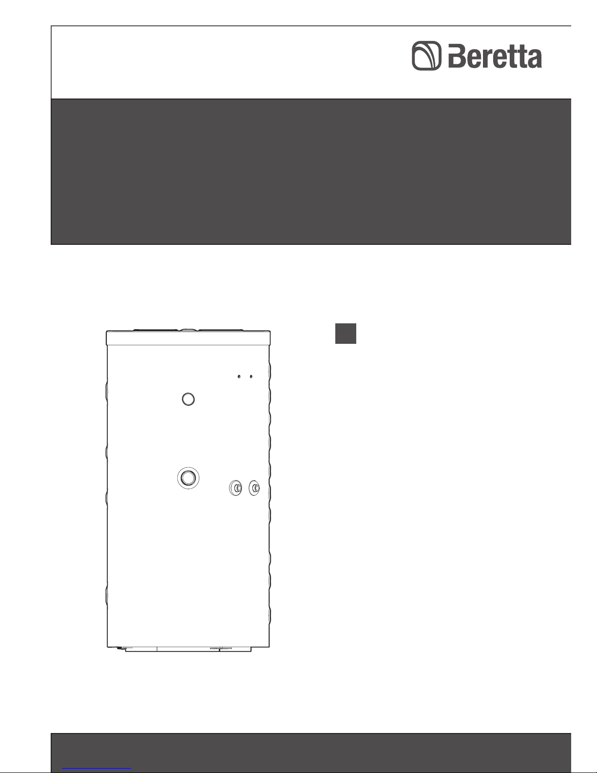
Beretta HYBRID STOR 750, HYBRID STOR 550, HYBRID STOR 430, HYBRID STOR 1000 Installation Manual
Installation Manual
Solar | combination storage cylinder triple coil
HYBRID STOR 430 - 550 - 750 - 1000
Installation Manual
EN
INSTALLATION MANUAL
2
Dear Installer,
Thank you for choosing a BERETTA HYBRID STOR, combination storage cylinder. You have
purchased a modern and quality product.
This instruction manual contains important instructions and precautions that must be observed
to ensure the trouble-free installation and efficient functioning of your BERETTA HYBRID STOR
combination storage cylinder.
Please accept our renewed thanks for your purchase.
Beretta
MODEL CODE
HYBRID STOR 430 20051862
HYBRID STOR 550 20051863
HYBRID STOR 750 20051864
HYBRID STOR 1000 20051866
RANGE
The following symbols are used in this manual:
b CAUTION! = Indicates actions that require caution and adequate preparation
a STOP! = Identifies actions that you MUST NOT do
This manual, Code 20051873 - Rev. 3 (12/15) is made up of 24 pages.

3
CONTENTS
1 SAFETY PRECAUTIONS ...........................................................................4
2 PRODUCT DESCRIPTION ......................................................................... 5
2.1 Description ..........................................................................................................................................5
2.2 Identification .......................................................................................................................................5
2.3 Design .................................................................................................................................................6
2.4 Technical specifications......................................................................................................................7
2.5 Accessories ......................................................................................................................................11
2.6 Water circuit ......................................................................................................................................12
2.7 Dimensions and water connections .................................................................................................13
3 INSTALLATION ......................................................................................... 15
3.1 Unpacking the product .....................................................................................................................15
3.2 Handling ...........................................................................................................................................15
3.3 Place of installation of the combined storage cylinder ....................................................................17
3.4 Installation in older systems and systems requiring modernisation ................................................17
3.5 Location of probes ............................................................................................................................17
3.7 Initial start-up ....................................................................................................................................18
3.6 Preparing for initial start-up ..............................................................................................................18
3.8 Checks during and after initial start-up ............................................................................................18
3.9 Preparing for extended periods of disuse ........................................................................................19
3.11 Maintenance .....................................................................................................................................20
3.12 Cleaning ............................................................................................................................................20
4 TROUBLESHOOTING .............................................................................. 21

INSTALLATION MANUAL
4
b As soon as you open the packaging,
check immediately that the contents are
all present and undamaged. Contact the
reseller from whom you purchased the
product if you notice any problems.
b This BERETTA HYBRID STOR combi-
nation storage cylinder must be installed
by a qualified installer. On completion of
the installation, the installer must issue
the owner with a declaration of conformity confirming that the installation has
been completed to the highest standards in compliance with the instructions
provided in this instruction manual, and
that it conforms to all applicable laws
and standards.
b This BERETTA HYBRID STOR combi-
nation storage heater must only be used
for the purpose specified and for which it
is designed. The manufacturer declines
all responsibility, contractual or other, for
damage to property or injury to persons
or animals caused by improper installation, adjustment, maintenance or use.
b If you notice any water leaking from the
cylinder, disconnect it immediately from
the mains electricity supply, shut off the
water supply, and notify your Technical
Assistance Centre or a qualified technician immediately.
b This combination storage cylinder must
be serviced at least once a year.
If the combination storage cylinder is not
going to be used for an extended period
of time, prepare it for shut-down as follows:
- Turn the system’s main power switch
OFF
- Drain the solar water circuit
- Close the fuel cock and heating water
cock
- Drain the central heating circuit and
domestic hot water circuit if there is
any risk of freezing
b Anti-freeze (propylene glycol) is availa-
ble separately and must be mixed with
water in a percentage varying from 30%
to 50%.
b This instruction manual is an integral
part of the appliance. It must be kept
safe and must ALWAYS accompany the
appliance, even if it is sold to another
owner or transferred to another user or
to another installation. If you damage or
lose this manual, order a replacement
immediately from your local Technical
Assistance Centre.
The operation of any appliance that uses
electrical power and water demands that a
number of fundamental safety precautions be
respected. In particular:
a Do not allow children or infirm persons to
operate the combination storage cylinder unsupervised.
a Do not touch the combination storage
cylinder when barefoot or wet.
a Never clean or service the combination
storage cylinder without first disconnecting it from the mains electricity supply
by turning the main power switch and
the control panel switch OFF.
a Do not interfere with any control devi-
ces without specific authorisation and
instructions from the manufacturer.
a Do not leave packaging material within
the reach of children, since it can become a potential hazard.
a If the pressure in the solar heating circuit
drops, do not top up with water alone,
since this increases the risk of damage
from freezing.
a Do not use connections or safety devi-
ces or fittings (expansion vessels, pipes,
insulation) that are not specifically designed and tested for use in solar heating
installations.
1 SAFETY PRECAUTIONS
5
2 PRODUCT DESCRIPTION
2.1
Description
HYBRID STOR triple coil combination storage
cylinders come in the form of an inertial (buffer) storage cylinder with three internal coils.
The bottom coil receives heat from the solar
circuit while the top coil receives heat from the
boiler. A third coil in stainless steel produces
domestic hot water.
The most important technical features of these
combination storage cylinders are:
- The cylinder and coils are specially designed and shaped for optimum performance
in terms of stratification, heat exchange and
replenishment times.
- The stainless steel, rapid heat exchange coil for domestic hot water production
is bacteriologically inert and guarantees
maximum hygiene and reduced lime scale
deposits.
- Water fittings are available at different
heights, permitting different boilers to be
used without reducing the stratification
effect.
- CFC-free polyurethane insulation and an
elegant external casing reduce heat loss
and improve efficiency.
- Excellent flexibility permits use in both high
and low temperature systems.
- Dimensions are extremely compact thanks
to the clever combination of an inertial storage cylinder and domestic hot water coil.
HYBRID STOR triple coil combination storage
cylinders can be connected to a special solar
controller and can be integrated in solar heating systems in which boilers or water heaters
serve as auxiliary heat generators
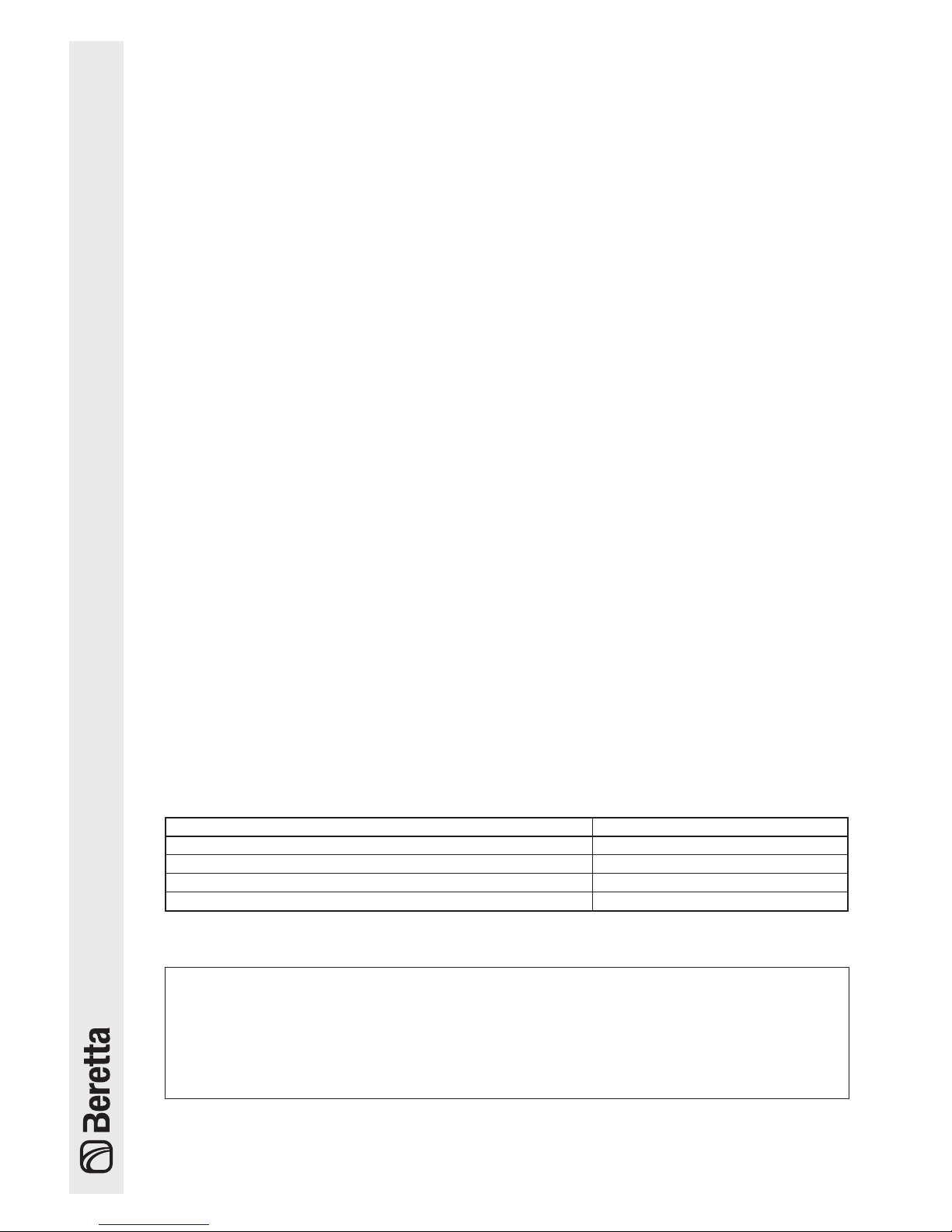
2.2
Identification
HYBRID STOR combination storage cylinders are identified by three plates:
Beretta Caldaie
Via Risorgimento, 13
23900 Lecco (LC)
Beretta Caldaie
Via Risorgimento, 13
23900 Lecco (LC)
Fabrication
Modele
kW
kW
Puiss.abs.sup.maxi
Pot.ass.sup.max.
Modello
Puiss.abs.inf.maxi
Pot.ass.inf.max.
BALLON SOLAIRE
Modele
Fabrication
Code
Année
Pression service max.
Alimentat. élect.
bar
V-Hz
Capacité ballon
l
067659IF
Collegamento di terra obbligatorio - Raccordement a la terre obligatoire
W
Puissance élect. absorbée
Puissance absorbée serpentin sup.[T° Primaire 80°C]
kW
Débit specifique sup. [∆T 35°C]
l/1'
BOLLITORE SOLARE
Modello
Matricola
Codice
Anno
Massima potenza assorbita sup.[T° Primario 80°C]
Portata specifica sup.[∆T 35°C]
Press. esercizio max.
Capacità del bollitore
Potenza elettric assorbita
Alimentazione elettrica
m
2
m
2
Superficie serpentino superiore
Surface serpentin supérieur
Superficie serpentino inferiore
Surface serpentin inférieur
b If these plates or any other means of clearly iden-
tifying the product are defaced, removed or lost, proper installation and servicing may be rendered difficult.
– Data plate
This lists the technical specifications and
performance of the product.
– Product identification plate
This states the name of the product.
– Serial number plate
This specifies the serial number, model,
consumption and capacity.
INSTALLATION MANUAL
6
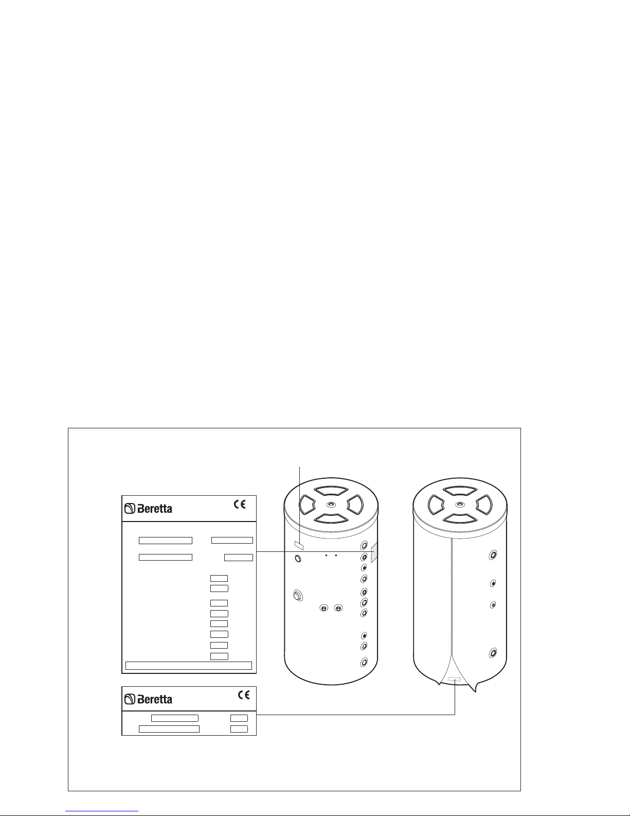
1
2
5
7
10
6
12
11
9
3
4
8
13
14
7
15
16
18
20
21
22
23
17
19
1 - Insulation
2 - Domestic cold water inlet
3 - Inertial storage cylinder
4 - Bottom coil
5 - Temperature sensor socket
6 - Sleeve for electric heating element (not sup-
plied)
7 - Boiler temperature sensor socket
8 - Top coil
9 - Storage cylinder temperature gauge
10 - Domestic hot water outlet
11 - DHW coil
12 - Vent valve fitting
13 - Inlet from boiler
14 - Inlet from 2nd boiler
15 - Central heating outlet
16 - Return to 2nd boiler
17 - Inlet from solar collector
18 - 50° C water return
19 - Return to solar collector
20 - Inlet from condensing boiler / 50°
C water return
21 - Solar controller temperature sen-
sor socket
22 - Return to condensing boiler /
Filling
23 - 30° C water return / Drain
2.3
Design
7
2.4
Technical specifications
(*) With ∆T = 35°C and primary temperature = 80°C.
Performance achieved with heat generator of suitable power, adjusted for a flow rate of 3000 l/h.
DESCRIPTION
HYBRID STOR
430 550 750 1000
Type of inertial storage cylinder Non vitrified
Inertial storage cylinder layout Vertical
Heat exchanger layout Vertical
Primary coils Smooth steel pipe
DHW coil Corrugated pipe in AISI 316 L stainless steel
Inertial storage cylinder capacity 407 520 732 898 l
Diameter with insulation 810 810 1000 1000 mm
Diameter without insulation 650 650 790 790 mm
Height 1650 2000 1855 2180 mm
Insulation thickness 70 90 mm
Temperature sensor socket diameter (boiler and solar
system)
16 Ø mm
Temperature sensor socket diameter 8 Ø mm
Temperature gauge sensor socket diameter 1/2" M Ø
Top primary coil water capacity 7,1 8,0 10,0 10,0 l
Bottom primary coil water capacity 11,0 12,8 17,4 19,8 l
DHW coil water capacity 23,6 23,6 30,4 30,4 l
Top primary coil heat exchange surface area 1,17 1,31 1,72 1,72 m
2
Bottom primary coil heat exchange surface area 1,80 2,10 2,90 3,34 m
2
DHW coil heat exchange surface area 4,5 4,5 5,8 5,8 m
2
Power absorbed by top primary coil (*) 25,0 26,0 30,0 30,0 kW
Maximum working pressure of inertial storage cylinder 3 5 bar
Maximum working temperature of inertial storage cylinder
99 °C
Maximum working pressure of primary coils 10 bar
Maximum working pressure of DHW coil 6 bar
Maximum working temperature of primary coils 99 °C
Maximum working temperature of DHW coil 99 °C
Recommended surface area of solar panel 6 8 12 14 m
2
Net weight 168 195 239 269 kg
Gross weight (with packaging) 189 215,5 254 284,4 kg
Heat loss according to EN 12897:2006 at ∆T=45 °C 60 68 156 175 W
Energy efficiency class B B D D
INSTALLATION MANUAL
8
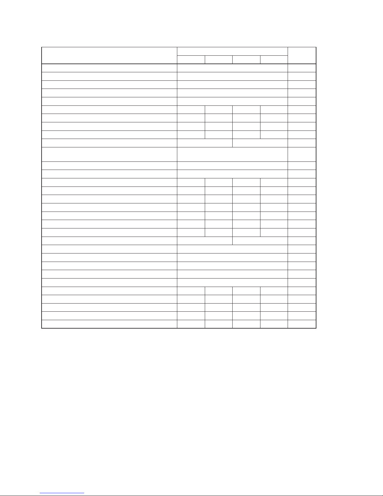
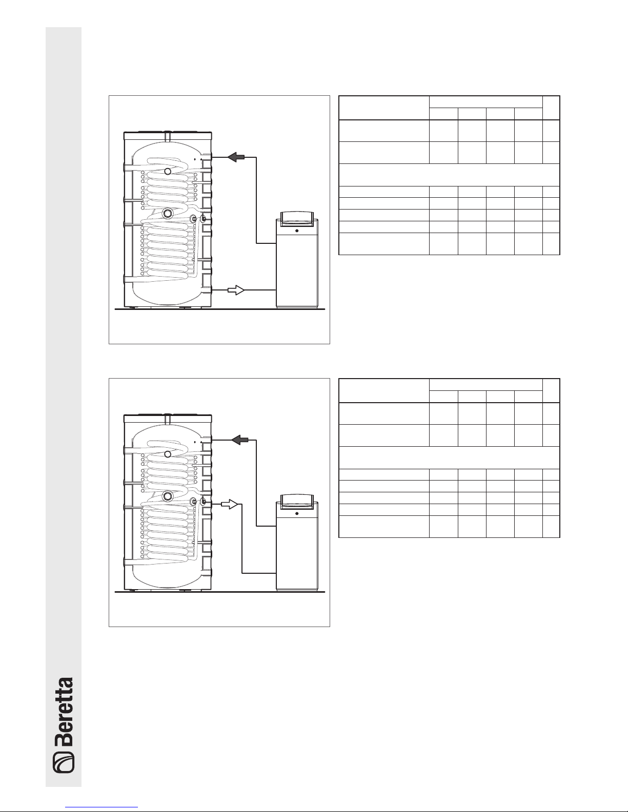
CONFIGURATION A
HYBRID STOR
Boiler
CONFIGURATION B
HYBRID STOR
Boiler
Descrizione
HYBRID STOR
430 550 750 1000
Domestic hot water
production (*)
3050 3300 3150 3200 l/h
Domestic hot water
production (**)
1970 2115 1980 2250 l/h
Water draw in 10 minutes with mean ∆T of 35° and
primary storage tank at:
90°C 600 670 800 800 l
80°C 425 470 670 670 l
70°C 370 400 570 570 l
60°C 220 280 285 285 l
Useful non-solar
volume (Vbu)
320 430 565 705 l
(*) With ∆T = 35°C and primary temperature = 80°C.
Performance achieved with boiler of suitable power
configured for a flow rate of 3000 l/h.
(**) With ∆T = 35°C and primary temperature = 80°C.
Performance achieved with boiler of suitable power
configured for a flow rate of 1500 l/h.
Descrizione
HYBRID STOR
430 550 750 1000
Domestic hot water
production (*)
2300 2400 2600 2650 l/h
Domestic hot water
production (**)
1650 1750 1900 1950 l/h
Water draw in 10 minutes with mean ∆T of 35° and
primary storage tank at:
90°C 350 400 420 560 l
80°C 260 310 350 470 l
70°C 200 220 285 350 l
60°C 130 160 200 240 l
Useful non-solar
volume (Vbu)
190 235 325 435 l
(*) With ∆T = 35°C and primary temperature = 80°C.
Performance achieved with boiler of suitable power
configured for a flow rate of 3000 l/h.
(**) With ∆T = 35°C and primary temperature = 80°C.
Performance achieved with boiler of suitable power
configured for a flow rate of 1500 l/h.
Performance of HYBRID STOR combination storage cylinder with boiler connected in:
 Loading...