

Beretta EXCLUSIVE GREEN RSI 16, EXCLUSIVE GREEN CSI 35, EXCLUSIVE GREEN CSI 25, EXCLUSIVE GREEN RSI 35, EXCLUSIVE GREEN RSI 25 User Manual
Page 1
EXCLUSIVE
GREEN
C.S.I. - R.S.I.
EN INSTALLER AND USER MANUAL
ES MANUAL DE INSTALACIÓN Y USO
PT MANUAL PARA INSTALAÇÃO E USO
HU TELEPÍTŐI ÉS FELHASZNÁLÓI KÉZIKÖNYV
RO MANUAL DE INSTALARE SI UTILIZARE
DK INSTALLATIONS- OG BRUGERVEJLEDNING
Page 2

2
EXCLUSIVE GREEN C.S.I. - R.S.I.
0694
BQ0479
EN
EXCLUSIVE GREEN boiler complies with basic requirements of the
following Directives: Gas directive 90/396/EEC; Yield directive 92/42/EEC;
Electromagnetic compatibility directive 89/336/EEC; Low-voltage directive
73/23/EEC; Regulation 677 for condensation boilers. Thus, it is ECmarked.
ES
La caldera EXCLUSIVE GREEN es conforme a los requisitos esenciales
de las siguientes Directivas: Directiva gas 90/396/CEE; Directiva
rendimientos 92/42/CEE; Directiva compatibilidad electromagnética 89/
336/CEE; Directiva baja tensión 73/23/CEE; Normativa calderas de
condensación 677. Y por lo tanto es titular de la marca CE.
PT
A caldeira EXCLUSIVE GREEN está conforme com os requisitos
essenciais das seguintes Directivas: Directiva gás 90/396/CEE; Directiva
rendimentos 92/42/CEE; Directiva compatibilidade electromagnética 89/
336/CEE; Directiva baixa tensão 73/23/CEE; Normativa s de condensação
677. É portanto titular de marcação CE.
HU
Az EXCLUSIVE GREEN kazán teljesíti az alábbi irányelvek lényegi
követelményeit: 90/396/EGK sz. gáz irányelv; 92/42/EGK sz. irányelv a
vízmelegítő kazánokról; 89/336/EGK sz. irányelv az elektromágneses
összeférhetőségről; 73/23/EGK sz. irányelv a kisfeszültségű
berendezésekről; Kondenzációs kazánokra vonatkozó 677 sz. szabvány.
Így jogosan viseli a CE-jelet.
RO
Centrala EXCLUSIVE GREEN este fabricata in conformitate cu cerintele
urmatoarelor Directive: Directiva gaz 90/396/EEC; Directiva eficienta 92/42/
EEC; Directiva compatibilitate electromagnetica 89/336/EEC; Directiva
voltaj redus 73/23/EEC; Regulamentul 677 referitor la boilerele cu
condensare. Prin urmare, este marcat cu simbolul CE.
DK
EXCLUSIVE GREEN kedlen opfylder kravene i følgende direktiver: Gas
direktiv 90/396/EEC;Yield direktiv 92/42/EEC;El direktiv 89/336/EEC;Lavvolt direktiv 73/23/EEC;Regulation 677 af kondenserende kedler. Kedlen er
EC-mærket.
EN
Installer’s-user’s manual ............................................................................ 4
Boiler operating elements ...................................................................... 121
Hydraulic circuit ...................................................................................... 122
Electric diagrams ................................................................................... 124
Circulator residual head ......................................................................... 131
ES
Manual para el instalador-usuario............................................................ 24
Elementos funcionales de la caldera ..................................................... 121
Circuito hidráulico .................................................................................. 122
Esquema eléctrico ................................................................................. 124
Altura de carga residual del circulador .................................................. 131
PT
Manual do instalador-usuário ................................................................... 44
Elementos funcionais da caldeira .......................................................... 121
Circuito Hidráulico .................................................................................. 122
Diagrama Eléctrico ................................................................................. 124
Altura total de elevação residual da bomba circuladora ........................ 131
HU
Telepítői kézikönyv-felhasználói kézikönyv .............................................. 64
A kazán funkcionális alkatrészei ............................................................ 121
Vízkeringetés ......................................................................................... 122
Villamos kapcsolási rajz ......................................................................... 124
A keringető szivattyú maradék emelőnyomása ..................................... 131
RO
Manual instalator-utilizator ...................................................................... 84
Elemenetele functionale ale centralei .................................................... 121
Circuit hidraulic ...................................................................................... 122
Scheme electrice ................................................................................... 124
Presiune reziduala circulator ................................................................. 131
DK
Installations- og brugervejledning .......................................................... 104
Kedelfunktioner ...................................................................................... 121
Hydrauisk kredsløb ................................................................................ 122
El diagrammer ........................................................................................ 124
Pumpe .................................................................................................... 131
Page 3
3
EXCLUSIVE GREEN C.S.I. - R.S.I.
EXCLUSIVE GREEN C.S.I. EXCLUSIVE GREEN R.S.I.
This handbook contains data and information for both users and installers. In detail:
• The chapters entitled “Installing the boiler, Water connections, Gas connection, Electrical connection, Filling and draining, Evacuating products of
combustion, Technical data, Programming parameters, Gas regulation and conversion” are intended for installers;
• The chapters entitled “Warnings and safety devices, Switching on and using” are for both users and installers.
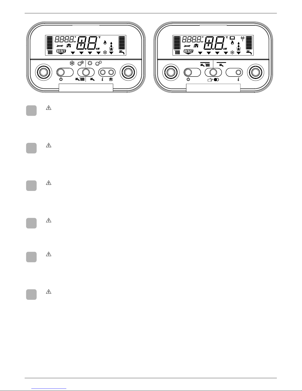
The control panel is different between GREEN C.S.I. and GREEN R.S.I. (see detail). Please read, in the booklet, the instructions referring to your boiler
model.
EN
Este manual contiene datos e informaciones destinados tanto al usuario como al instalador. En especial:
• Los capítulos “Instalación de la caldera, Conexiones hidráulicas, Conexión gas, Conexión eléctrica, Llenado y vaciado, Evacuación productos de la
combustión, Datos técnicos, Programación parámetros, Regulación y Transformación gas” son los que se refieren al instalador;
• Los capítulos “Advertencias y seguridades, y Encendido y funcionamiento” son los que se refieren tanto al usuario como al instalador.
El panel de mando es diferente entre los modelos GREEN C.S.I. y GREEN R.S.I. (ver dibujo). Rogamos consulten el manual para encontrar las
instrucciones relativas a su modelo de caldera.
ES
Este livrete inclui dados e informações destinados quer ao usuário quer ao instalador. Especificadamente:
• Os capítulos “Instalação da caldeira, Conexões hidráulicas, Conexão gás, Ligação eléctrica, Enchimento e esvaziamento, Evacuação dos produtos da
combustão, Dados técnicos, Programação parâmetros, Regulação e Transformação gás” são aqueles referidos ao instalador:
• Os capítulos “Advertências e seguranças e Ignição e Funcionamento” são aqueles referidos quer ao usuário quer ao instalador.
Os modelos GREEN C.S.I. e GREEN R.S.I. têm os painéis de comando diferentes (veja-se o desenho). Sugerimos consultar o manual para as
instruções relativas ao seu modelo de caldeira.
PT
Jelen kézikönyv mind a felhasználó mind a telepítő számára tartalmaz információkat. Pontosabban:
• A telepítő részére szánt fejezetek “A kazán telepítése, Vízbekötések, Gázbekötés, Elektromos bekötés, Feltöltés és a berendezés víztelenítése,
Égéstermék elvezetés, Műszaki adatok, Paraméterek programozása, Gázbeállítások és gáztípusváltás”;
• A telepítő és a felhasználó részére egyaránt szánt fejezetek az “Általános tudnivalók és biztonsági előírások, Begyújtás és működés”.
A GREEN C.S.I. és GREEN R.S.I. (lásd rajzon) modellek vezérlőpaneljei különbözőek. Kérjük, olvassa el az Ön kazánjára vonatkozó kezelési utasítást.
HU
Acest manual contine date si informatii atat pentru utilizator cat si pentru instalator. Si anume:
• Capitolele intitulate “Instalarea cazanului, Conectare la reteaua de apa, Conectare la reteaua de gaz, Conexiuni electrice, Umplerea si golirea instalatiei,
Evacuarea produselor de ardere, Date tehnice, Programarea parametrilor, Reglare si conversie gaz” sunt dedicate instalatorilor;
• Capitolele intitulate “Avertizari si masuri de siguranta, Pornire si utilizare” sunt dedicate atat instalatorilor cat si utilizatorilor.
Panoul de comanda difera intre modelele GREEN C.S.I. si GREEN R.S.I. (vezi detalii). Va rugam sa cititi din manual instructiunle specifice modelului
dumneavoastra.
RO
Denne vejledning indeholder oplysninger til både installatør og bruger.
• Afsnit: ‚Installation af kedlen, Rør-forbindelser, Gas tilslutning, El-forbindelser, Påfyldning og aftapning, Aftræk, Tekniske data, Indstilling af parametre,
Omstilling mellem gasarter‘ henvender sig til installatører og servicefirmaer;
• Afsnit: ‚Sikkerhed, opstart og funktion‘ henvender sig sig til både bruger og installatør.
Kontrolpanelet på GREEN R.S.I. er forskellige. Gennemlæs vejledningen til den valgte model.
DK
Page 4
4
EXCLUSIVE GREEN C.S.I. - R.S.I.
1 - GENERAL SAFETY DEVICES
The boilers produced in our factory are built with care down to the last
component to protect both the user and installer from eventual accidents.
We therefore recommend qualified personnel that after working on the
product they should pay particular attention to the wiring, especially the
bare wires, that must not be exposed outside the terminal board for any
rason to prevent any contact with the live parts of the wiring.
This instructions manual is integral parts of the product. Make sure they
remain with the boiler, even if it is transferred to another owner or user or
moved to another heating system. In case of loss or damage, please contact
your local Technical Assistance Service for a new copy.
This boiler may only be installed and serviced by qualified fitters who satisfy
the requirements of local rules. Work must be done in compliance with
regulations in force and subsequent updates.
The boiler must be serviced at least once a year. This should be booked in
advance with the Technical Assistance Service.
The installer shall instruct the user in the operation of the boiler and the
safety devices.
This boiler may only be used for what it was expressly built to do. The
manufacturer declines all contractual and non-contractual liability for injury
to persons or animals or damage to property deriving from errors made
during installation, adjustment and servicing and from improper use.
This appliance is used to produce hot water and must therefore be
connected to a heating and/or a domestic hot water system, according to
its performance and power.
After removing the packaging, make sure the contents are undamaged
and complete. If this is not the case, contact your dealer.
The safety valve outlet must be connected to a suitable collection and
venting system. The manufacturer declines all liability for any damage
caused by the safety valve.
The safety and automatic adjustment devices on the appliance must never
be modified during its lifetime, except by the maker or dealer.
If the appliance develops a fault and/or works badly, switch it off and do not
attempt to repair it yourself.
Immediately after installation, inform the user that:
- in the event of leaks, he/she must shut off the water supply and promptly
inform the Technical Assistance Service
- GREEN C.S.I.: he/she must check from time to time to make sure the
symbol is not lit on the control panel. This symbol means that the
pressure in the water system is incorrect. If necessary, fill the system
as described in the paragraph “Boiler functions”
- GREEN R.S.I.: must periodically check, on the display, that the pressure
value is between 1 and 1,5 bar; if not fill the system as described in the
paragraph “Boiler functions”
- if the boiler is not planned to be used for a long period, he/she should
call in the Technical Assistance Service to perform the following
operations:
- turn off the main boiler and general system switches
- close the gas and water taps on both the heating (GREEN C.S.I.-
GREEN R.S.I.) and domestic hot water circuits (GREEN C.S.I. only)
- drain the heating (GREEN C.S.I.-GREEN R.S.I.) and domestic hot
water (GREEN C.S.I. only) circuits to prevent freezing.
Connect the outlet collector to a suitable outlet system (refer to chapter 5).
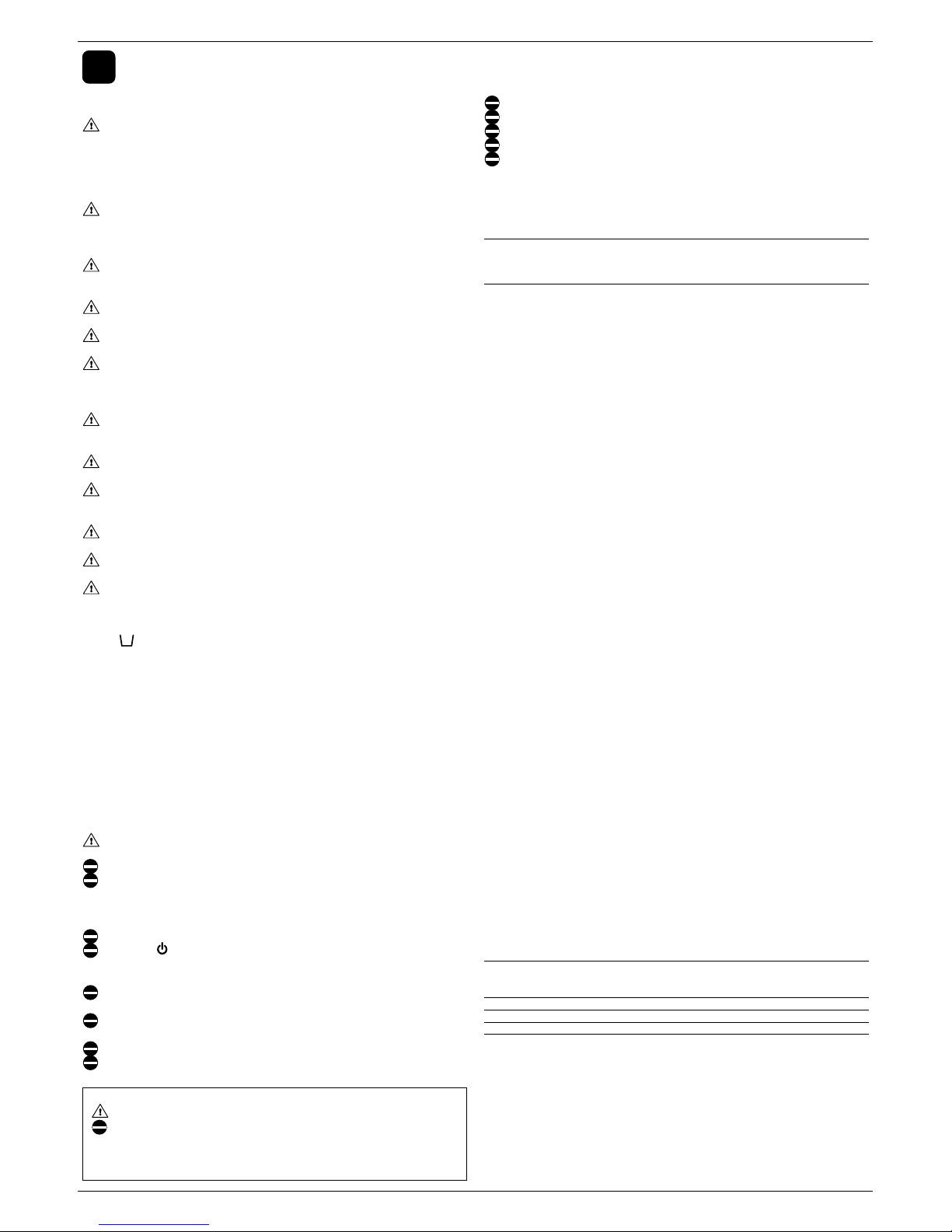
Safety measures:
the boiler should not be used by children or unassisted disabled people
electrical devices or equipment, such as switches, appliances, etc., should
not be used if there is a smell of gas or fumes. If there is a gas leak, open
all the doors and windows to ventilate the area, turn off the general gas tap
and immediately call the Technical Assistance Service
do not touch the boiler barefoot or if parts of your body are wet or damp
press the button until “- -” is shown on the display and disconnect the
electricity supply by turning off the two-position system switch, before
cleaning
it is forbidden to modify the safety or adjustment devices without the
manufacturer’s permission and relative instructions
do not pull, detach or twist the wires from the boiler even if they are not
connected to the power supply
do not block or reduce the size of the ventilation openings in the room
do not leave inflammable containers or substances in the room
EN
ENGLISH
The following symbols are used in this manual:
CAUTION = operations requiring special care and adequate preparation
NOT ALLOWED = operations that MUST NOT be performed
R.S.I.: DHW functions refer only if a water tank is connected (accessory
available on request).
keep packaging out of reach of children
only use appliance for purposes it is devoted to
do not lean any object on the boiler
do not tamper with sealed elements
it is forbidden to block the condensate outlet.
2 - BOILER INSTALLATION
Boiler must only be installed by qualified personnel.
Boiler is available in the following models:
Type
combined
CH only
Category
C
C
Model
C.S.I.
R.S.I.
Power
25-35 kW
16-25-35 kW
Inlet
water
15÷20
limpid
Water in
heating
circuit
7÷8
-
-
um
°F
Parameters
PH
Hardness
Appearance
Exclusive GREEN C.S.I. is a C-type condensation wall-mounted boiler for
heating and producing domestic hot water; Exclusive GREEN R.S.I. is a Ctype condensation wall-mounted boiler and is able to operate in different
conditions:
- CASE A: only heating. The boiler doesn’t supply domestic hot water
- CASE B: only heating with water tank connected, managed by a thermostat,
to prepare domestic hot water
- CASE C: only heating with water tank connected (kit available upon request),
managed by a temperature sensor, to prepare domestic hot water. Connecting
a water tank not supplied by us, please be sure that the NTC sensor ised has
the following features: 10 kOhm at 25°C, B 3435 ±1%.
Depending on the type of installation selected, it is necessary to set the parameter
“domestic hot water mode”. Refer to page 19 for description and setting
parameter operations.
This type of appliance can be installed in any kind of room as long as the fumes
discharge and the comburent air intake are taken outside the room.
The following types of fumes outlet are available for this kind of boiler: B23P;
B53P; C13,C13x; C23; C33,C33x; C43,C43x; C53,C53x; C63,C63x; C83,C83x.
Installation must comply with local standards and regulations in force.
For proper installation, we remind you that:
- the boiler must not be installed over a kitchen or any other cooking equipment
- minimum spaces are to be left in order to allow maintenance operations: at
least 2,5 cm every side and 20 cm under the boiler
- it is forbidden to leave inflammable substances in the room
- suitably insulate heat-sensitive walls (e.g.: in wood).
Support plate and integrated pre-installation template are provided for with the
boiler (
Fig. 1.1).
Mounting instructions:
- fix the boiler support plate (F) with the template (G) to the wall and use a
plumb to check that it is perfectly horizontal
- trace out 4 holes (Ø 6 mm) for fixing the boiler support plate (F) and 2 holes
(Ø 4 mm) for fixing the pre-installation template (G)
- make sure all the measurements are correct, then drill holes in the wall using
a drill and point with the diameter given previously
- fix the plate to the wall by the supplied anchor screws
- make hydraulic connections.
After installing the boiler, the screws D1 (
Fig. 1.2) can be removed. After installing
the boiler and connecting it to the water and gas supplies, fit the lower cover (A-
B, Fig. 1.3) so that its hooks slip into the relative slots in the lower part of the
boiler. Fix the lower cover with the screw C (
Fig. 1.4) contained in the
documentation envelope in the boiler.
Cleaning the system and characteristics of heating circuit water
After installing a new system or replacing a boiler, clean the heating system. To
ensure the product works correctly, after cleaning, additivating and/or chemically
treating the system (e.g.: anti-freeze, film-formers, etc.), make sure the
characteristics of the water satisfy the parameters indicated in the table.
Page 5

5
ENGLISH
3 - HYDRAULIC CONNECTIONS
Position and dimensions of hydraulic connections are specified in figure 1.1:
A - CH return 3/4”
B - CH delivery 3/4”
C - Gas connection 3/4”
D - DHW outlet 1/2” (GREEN C.S.I. only)
E - DHW inlet 1/2” (GREEN C.S.I. only)
F - Support plate
G - Pre-installation template
If water hardness exceeds 28°Fr, it is recommended to use water softeners, to
prevent any limestone deposit in boiler due to excessively hard water.
4 - INSTALLING THE EXTERNAL PROBE
The correct position of the external probe is essential for the climatic control
function to run properly.
The probe must be installed outside the building to be heated, at about 2/3 of
the height of the NORTHERN or NORTHWESTERN face, far from flue pipes,
doors, windows and sunny areas.
Attaching the external probe to the wall
(Fig. 1.6)
- To access the terminal board and anchor holes, unscrew the plastic probe
cover from the housing by rotating it anticlockwise
- Mark the points where the holes will be drilled using the probe housing as a
template
- Remove the box and drill holes for 5x25 expansion grips
- Fix the housing to the wall using the two supplied expansion grips
- Unscrew the cable-holding nut, insert the bipolar cable (with a cross section
between 0,5 and 1mm
2
, not supplied) for the connection between the probe
and the boiler
- For the electrical connection between the external probe and the boiler, refer
to the chapter “Electric connection”
- Tighten the cable-holding nut properly and close the cover of the protective
box.
The probe must be positioned on a smooth surface. In the case of a brick
wall or a wall with an irregular surface, provision must be made for a smooth
contact surface.
The maximum length of the connection between the external probe and
the boiler is 30 m.
The connection cable between the probe and the boiler must not have
connections. If these prove to be necessary, they must be made watertight
and suitably protected.
Any ducts for the connection cable must be separate from other power
lines (230 V.a.C.).
5 - CONDENSATE COLLECTION
The outlet collector (A, Fig. 1.7) collects: the condensate water, any evacuation
water from the safety valve and the system outlet water.
The collector must be connected, by means of a rubber pipe (not supplied),
to a suitable collection and evacuation system in the storm water outlet
and in compliance with current regulations.
The external diameter of the collector is 20 mm: we therefore suggest
using an Ø 18-19 mm pipe, to be closed with a suitable clamp (not supplied).
The manufacturer is not responsible for any damage caused by the lack of
a collection system.
The outlet connection line must have a guaranteed seal.
The manufacturer of the boiler is not responsible for any flooding caused
by interventions of the safety valve.
6 - GAS CONNECTION
Before connecting appliance to gas pipe network, check the following:
- regulations in force are met
- gas type used is the same as set for appliance operation
- pipes are clean.
Gas must be piped externally. If the pipe goes through a wall it must go through
the central opening in the lower part of the template. It is recommended to
install an appropriately sized filter on the gas line in case gas from the mains
contains some small solid particles. After installation make sure that all the
joints have been made airtight conforming to standard installation practices.
7 - ELECTRIC CONNECTION
To access the electrical connections, proceed as follows:
- unscrew the lower cover fixing screw (C, Fig. 1.4)
- pull the cover towards you and remove (A-B) (Fig. 1.5)
- loosen the fixing screws (D) and remove the shell (
Fig. 1.2)
- lift up the panel and turn it forwards
- open the terminal board covers making them slide in the direction of the
arrows (Fig. 1.8: E high voltage connections 230 V, F low voltage connections,
G water tank sensor connections only GREEN R.S.I.).
Connect the appliance to the mains power supply with a switch featuring a
distance of at least 3,5 mm (EN 60335-1, category III) between each wire. The
appliance uses alternating current at 230 Volt/50 Hz, has a power input of 130
W (16kW R.S.I. - 25kW C.S.I. - 25kW R.S.I.) and 175 W (35kW R.S.I. - 35kW
C.S.I.) and complies with EN 60335-1 standard. Connect the boiler to a safe
earth circuit according to current legislation.
Live and neutral (L-N) connections should also be respected.
The boiler can operate with phase-neutral or phase-phase power supply. For
floating power supply, without an earth-bonded conductor, it is necessary to
use an insulation transformer with secondary anchored to ground.
The earth conductor must be a couple of cm longer than the others.
Gas and/or water pipes may not be used to earth electrical equipment.
The installer is responsible for making sure that the appliance has an
adequate earthing system; the manufacturer shall not be held liable for
eventual damages caused by incorrect usage or failing to earth the boiler.
Use the supplied power cable to connect the boiler to the mains power supply.
Connect the ambient thermostat and/or time clock as shown in the electrical
diagram on page
125.
When replacing the power cable, use a HAR H05V2V2-F cable, 3 x 0,75
mm
2
, Ø max. external 7 mm.
8 - FILLING AND EMPTYING THE SYSTEM
The central heating system can be filled up once the water mains have been
connected up.
This must be done while the installation is cold by:
- giving two or three turns to the cap of the automatic air vent valve (A,
Fig. 1.9)
to open it;
- making sure the cold water inlet tap is open (B, Fig. 1.9) (GREEN C.S.I.
only)
- opening the filling tap (C, on the boiler for GREEN C.S.I., external for GREEN
R.S.I.) until the pressure on the hydrometer (D) is between 1 and 1,5 bar
(blue zone) (
Fig. 1.9).
Close the filling tap after filling it up.
The boiler is equipped with an efficient air separator so that there is no need to
do anything manually.
The burner only ignites when air venting has finished.
NOTE: air extraction from the boiler takes place automatically, through two
automatic bleeding valves, A and E.
The first is situated on the pump, while the second is inside the air chamber.
NOTE (GREEN C.S.I. only): the boiler is also equipped with a semi-automatic
filling system. The first system-filling operation must be carried out by opening
tap C with the boiler turned off.
NOTE (GREEN R.S.I. only): manual filling tap is not supplied with the boiler,
foresee one external or verify if external water tank has one.
Before starting to empty it, remove the electrical feeder by positioning the general
switch for the system on “off”.
- Close the interception devices for the thermal system
- Loosen the system outlet valve (F) manually
- The water from the system is discharged through the outlet collector (G).
DHW system emptying (GREEN C.S.I. only)
The hot water system must be emptied every time there is risk of freezing by:
- turning off the tap at the mains
- turning on all the hot and cold taps
- emptying out the lowest parts of the system.
ATTENTION
The collector must be connected, by means of a rubber pipe (not supplied), to
a suitable collection and evacuation system in the storm water outlet and in
compliance with current regulations. The external diameter of the collector is
20 mm: we therefore suggest using an Ø18-19 mm pipe, to be closed with a
suitable clamp (not supplied). The manufacturer is not responsible for any
damage caused by the lack of a collection system.
Page 6

6
EXCLUSIVE GREEN C.S.I. - R.S.I.
INSTALLATION “SEALED” (TYPE C)
Boiler is a C-type appliance (sealed chamber) and must be safely connected to
fume exhaustion duct and burning air suction duct, both getting outside;
appliance cannot operate without these ducts.
Concentric outlets (Ø 60-100)
(Fig. 1.14)
Concentric ducts may be placed in the most suitable direction for installation
requirements but special care must be taken as regards the external temperature and the length of the duct.
Rectilinear length means without bends, outlet ends and connections.
The fumes outlet duct must slope by 1% towards the condensate collector.
Uninsulated fumes outlets are potential hazards.
The boiler automatically adapts ventilation according to the type of
installation and the length of the duct.
Do not obstruct or narrow the comburent air inlet duct in any way.
To install follow the instructions supplied with the kit.
Max length fumes
outlet duct Ø 80 mm
48 m
48 m
60 m
Pressure drop for each
bend (45°/90°) [m]
0,5 / 0,8
16 R.S.I.
25 C.S.I.-R.S.I.
35 C.S.I.-R.S.I.
Max linear length concentric
duct Ø 60-100 mm
7,80 m
7,80 m
7,80 m
Pressure drop for each
bend (45°/90°) [m]
0,5 / 0,8
16 R.S.I.
25 C.S.I.-R.S.I.
35 C.S.I.-R.S.I.
Horizontal
Max linear length concentric
duct Ø 60-100 mm
8,80 m
8,80 m
8,80 m
Pressure drop for each
bend (45°/90°) [m]
0,5 / 0,8
16 R.S.I.
25 C.S.I.-R.S.I.
35 C.S.I.-R.S.I.
Vertical
Max linear length concentric
duct Ø 80-125 mm
17 m
17 m
28 m
Pressure drop for each
bend (45°/90°) [m]
0,5 / 0,9
16 R.S.I.
25 C.S.I.-R.S.I.
35 C.S.I.-R.S.I.
Twin outlets (Ø 80) (Fig. 1.15)
The split duct can be aimed in the most suitable direction for installation needs.
The combustion-supporting air intake duct must be connected to the entrance
after having removed the closing cap, attached with three screws, and having
attached a suitable adaptor.
The fumes outlet duct must be connected to the fumes outlet after having
installed a suitable adaptor.
For the installation process, follow the instructions supplied with the kit for the
specific accessory for condensation boilers.
The fumes outlet duct must slope by 1% towards the condensate collector.
The boiler automatically adapts ventilation according to the type of installation and the length of the duct. Do not obstruct or narrow the comburent
air inlet duct in any way.
For an indication of the maximum lengths of every single pipe, refer to the
graphs (Fig. 1.16).
Using longer ducts causes a loss in the power of the boiler.
Max length
twin duct Ø 80 mm
40 + 40 m
40 + 40 m
50 + 50 m
Pressure drop for each
bend (45°/90°) [m]
0,5 / 0,8
16 R.S.I.
25 C.S.I.-R.S.I.
35 C.S.I.-R.S.I.
Rectilinear length means without bends, outlet ends and connections.
Suggestions to correctly eliminate air from the heating system and
boiler (Fig. 8.2)
We recommend carrying out the sequence of operations given below during
first installation or with extraordinary maintenance work:
1. Using a CH11 spanner open the manual air vent valve located above the air
box; the tube supplied with the boiler must be connected to the valve to let
out the water into an outside container.
2. Open the manual system filling stopcock on the water group, wait until the
water starts coming out of the valve;
3. Switch on the boiler leaving the gas cock closed;
4. Use the room thermostat or the remote control panel to activate request for
heat so that the three-way will turn to heating;
5. Turn on a tap to activate request for hot water (for instantaneous boilers
only; use the water heater thermostat for boilers just for heating connected
to an external water heater) for an interval of 30” every minute to make the
three-way cycle from heating to hot water and vice versa about ten times
(the boiler will be go into alarm as there is no gas under these circumstances,
it must therefore be reset every time this happens);
6. Continue the sequence until water only comes out of the manual air vent
valve and the flow of air has finished; close the manual air vent valve at this
point;
7. Make sure the system is at the correct pressure (1 bar is ideal);
8. Close the manual system filling stopcock on the water group;
9. Open the gas cock and ignite the boiler.
9 - FUMES EXHAUSTION AND BURNING AIR SUCTION
EXHAUSTION CONFIGURATIONS (Fig. 1.11-1.12)
Boiler is homologated for the following exhaustion configurations:
B23P-B53P - Suction in room and discharge outside
C13 - Concentric wall exhaustion. Pipes can separately start from boiler, but
outlets must be concentric or close enough to be subject to similar wind
conditions (within 50 cm)
C23 - Concentric exhaustion in common chimney (suction and exhaustion in
the same chimney)
C33 - Concentric roof exhaustion. Outlets like C13
C43 - Exhaustion and suction in common separate chimneys, but subject to
similar wind conditions
C53 - Wall or roof separate exhaustion and suction in different pressure areas.
Exhaustion and suction must never be located on opposite walls
C63 - Exhaustion and suction with separately certified and sold pipes (1856/1)
C83 - Single or common chimney exhaustion and wall suction
Refer to regulations in force for exhaustion of combustion products.
Boiler is provided for without fume exhaustion/air suction kit, since forced draught
sealed chamber accessories can be used, as they better adapt to installation
characteristics.
For fume extraction and burning air restoration in boiler, use original pipes or
other EC-certified pipes with equivalent characteristics; check connection is
correct as shown on instructions fume accessories provided for with. More
appliances can be connected to a single chimney, provided that all appliances
are sealed chamber type.
“FORCED OPEN” INSTALLATION (TYPE B23P-B53P, intake inside and
outlet outside) - Fumes outlet duct Ø 80 mm
(Fig. 1.13)
The fumes outlet duct can be aimed in the most suitable direction for installation
needs. To install follow the instructions supplied with the kit.
In this configuration, the boiler is connected to the Ø 80 mm fumes outlet
duct by means of a Ø 60-80 mm adaptor.
In this case, the combustion supporting air is taken from the room in which
the boiler is installed, which must be a suitable and ventilated technical
room.
Non-insulated fumes outlet ducts are potential sources of danger.
Provision must be made for a 1% slope of the fumes outlet duct towards
the boiler.
Concentric outlets (Ø 80-125)
(Fig. 1.14)
For this installation it is necessary to install the suitable adaptor kit. Ducts may
be placed in the most suitable direction for installation requirements. For the
installation process, follow the instructions supplied with the kit for the specific
accessory for condensation boilers.
Page 7

7
ENGLISH
10 - TECHNICAL DATA
CH Nominal thermal flow rate
Nominal thermal power (80°/60°)
Nominal thermal power (50°/30°)
Reduced thermal flow rate
Reduced thermal power (80°/60°)
Reduced thermal power (50°/30°)
DHW* Nominal thermal flow rate
Maximum thermal power**
Reduced thermal flow rate**
Minimum thermal power**
Working efficiency Pn max - Pn min (80-60°)
Working efficiency 30% (47° return)
Combustion efficiency
Working efficiency Pn max - Pn min (50-30°)
Working efficiency 30% (30° return)
Electric power
Category
Supply voltage
Protection level
Chimney and skirt losses with burner off
CH operation
Maximum pressure - temperature
Minimum pressure for standard working/operating
Selection field of CH water temperature
Pump maximum head available for system
capacity
Membrane expansion tank
Expansion vessel pre-charge (CH)
DHW operation*
Maximum pressure
Minimum pressure
Hot water quantity ∆t 25° C
∆t 30° C
∆t 35° C
DHW minimum capacity
Selection field of DHW temperature
Flow regulator
Gas pressure
Natural gas pressure (G20)
LPG pressure (G31)
Hydraulic connections
CH input-output
DHW input-output (GREEN C.S.I.)
Water tank delivery-return (GREEN R.S.I.)
Gas input
Boiler dimensions and weight
Height
Width
Depth
Weight
Fan performance
Fan residual head, pipes 0,5 + bend 90° (intake+discharge)
Flow rates (G20)
Air capacity
Fumes capacity
Mass flow (max-min)
Fume exhaustion and air suction concentric pipe
Diameter
Max lenght
Loss for a 90°/45° bend
Hole in wall (diameter)
Diameter
Max lenght
Fume exhaustion and air suction separated pipe
Diameter
Max lenght
Loss for a 90°/45° bend
Forced open installation (B23P-B53P)
Diameter
Max lenght
Loss for a 90°/45° bend
Nox
Emission values at maximum and minimum of gas G20 ****
Maximum CO s.a. lower than
CO
2
NOx s.a. lower than
∆t fumes
Minimum CO s.a. lower than
CO
2
NOx s.a. lower than
∆t fumes
kW
kcal/h
kW
kcal/h
kW
kcal/h
kW
kcal/h
kW
kcal/h
kW
kcal/h
kW
kcal/h
kW
kcal/h
kW
kcal/h
kW
kcal/h
%
%
%
%
%
W
V - Hz
IP
%
bar
bar
°C
mbar
l/h
l
bar
bar
bar
l/min
l/min
l/min
l/min
°C
l/min
mbar
mbar
Ø
Ø
Ø
Ø
mm
mm
mm
kg
Pa
Nm
3
/h
Nm
3
/h
gr/s
mm
m
m
mm
mm
m
mm
m
m
mm
m
m
class
p.p.m.
%
p.p.m.
°C
p.p.m.
%
p.p.m.
°C
25
21500
24.43
21006
26.13
22468
6
5160
5.86
5041
6.44
5537
25
21500
25
21500
6
5160
6
5160
97.7-97.7
101.2
97.9
104.5-107.3
107.1
130
II2H3P
230-50
X5D
0.10-0.80
3-90
0.25-0.45
20-80
300
1000
10
1
6
0.15
14.3
12
10.2
2
35-60
10
20
37
3/4"
1/2"
3/4"
845
453
358
44
110
31.237
34
11.32-2.72
60-100
7.8
0.85/0.5
105
80-125
17***
80
40+40
0.8/0.5
80
48
0.8/0.5
5
180
9
50
34
40
9.3
40
28
C.S.I. 25 kW
34.6
29756
33.74
29012
36.75
31601
7
6020
6.88
5918
7.55
6490
34.6
29756
34.6
29756
7
6020
7
6020
97.5-98.3
102.1
97.8
106.2-107.8
108.6
175
II2H3P
230-50
X5D
0.10-0.80
3-90
0.25-0.45
20-80
300
1000
10
1
6
0.15
19.8
16.5
14.2
2
35-60
14
20
37
3/4"
1/2"
3/4"
845
453
359
47
195
43.231
46.701
015.67-3.17
60-100
7.8
0.85/0.5
105
80-125
28***
80
50+50
0.8/0.5
80
60
0.8/0.5
5
250
9
70
54
40
9
60
36
C.S.I. 35 kW
16
13760
15.6
13416
16.8
14434
3.5
3010
3.4
2890
3.7
3148
-
-
-
-
-
-
-
-
97.5-96.0
101.1
97.6
104.9-104.6
107.8
130
II2H3P
230-50
X5D
0.10-0.80
3-90
0.25-0.45
20-80
300
1000
10
1
-
-
-
-
-
-
-
-
20
37
3/4"
3/4"
3/4"
845
453
358
43
57
20.446
22.05
7.41-1.62
60-100
7.8
0.85/0.5
105
80-125
17***
80
40+40
0.8/0.5
80
48
0.8/0.5
5
91
8.8
16
50
10
8.8
15
39
R.S.I. 16 kW
25
21500
24.43
21006
26.13
22468
6
5160
5.86
5041
6.44
5537
-
-
-
-
-
-
-
-
97.7-97.7
101.2
97.9
104.5-107.3
107.1
130
II2H3P
230-50
X5D
0.10-0.80
3-90
0.25-0.45
20-80
300
1000
10
1
-
-
-
-
-
-
-
-
20
37
3/4"
3/4"
3/4"
845
453
358
41
110
31.237
33.744
11.32-2.72
60-100
7.8
0.85/0.5
105
80-125
17***
80
40+40
0.8/0.5
80
48
0.8/0.5
5
180
9
50
34
40
9.3
40
28
R.S.I. 25 kW
34.6
29756
33.74
29012
36.75
31601
7
6020
6.88
5918
7.55
6490
-
-
-
-
-
-
-
-
97.5-98.3
102.1
97.8
106.2-107.8
108.6
175
II2H3P
230-50
X5D
0.10-0.80
3-90
0.25-0.45
20-80
300
1000
10
1
-
-
-
-
-
-
-
-
20
37
3/4"
3/4"
3/4"
845
453
359
43
195
43.231
46.701
15.67-3.17
60-100
7.8
0.85/0.5
105
80-125
28***
80
50+50
0.8/0.5
80
60
0.8/0.5
5
250
9
70
54
40
9
60
36
R.S.I. 35 kW
* DHW values refer to GREEN C.S.I. models.
** Average value among various sanitary running conditions.
*** Estimated with one 90° bend; 16 extensions of 1 meter and a horizontal exhaust of 1 meter (16kW and 25kW),
27 extensions of 1 meter and a horizontal exhaust of 1 meter (35kW).
**** Tested with Ø60-100 concentric - lenght 0,85m - water temperature 80-60°C.
Page 8

8
EXCLUSIVE GREEN C.S.I. - R.S.I.
11 - MULTIGAS TABLE
Lower Wobbe index (15°C-1013 mbar)
Lower heat value
Supply nominal pressure
Supply minimum pressure
EXCLUSIVE GREEN C.S.I. 25 kW
Number of main burner nozzles
Burner diameter
Gas diaphragm
Burner length
CH maximum gas capacity
DHW maximum gas capacity
CH minimum gas capacity
DHW minimum gas capacity
Numbers of fan revolutions at slow start
Maximum number of fan revolutions
Minimum number of fan revolutions
EXCLUSIVE GREEN C.S.I. 35 kW
Number of main burner nozzles
Burner diameter
Gas diaphragm
Burner length
CH maximum gas capacity
DHW maximum gas capacity
CH minimum gas capacity
DHW minimum gas capacity
Numbers of fan revolutions at slow start
Maximum number of fan revolutions
Minimum number of fan revolutions
EXCLUSIVE GREEN R.S.I. 16 kW
Number of main burner nozzles
Burner diameter
Gas diaphragm
Burner length
CH maximum gas capacity
CH minimum gas capacity
Numbers of fan revolutions at slow start
Maximum number of fan revolutions
Minimum number of fan revolutions
EXCLUSIVE GREEN R.S.I. 25 kW
Number of main burner nozzles
Burner diameter
Gas diaphragm
Burner length
CH maximum gas capacity
CH minimum gas capacity
Numbers of fan revolutions at slow start
Maximum number of fan revolutions
Minimum number of fan revolutions
EXCLUSIVE GREEN R.S.I. 35 kW
Number of main burner nozzles
Burner diameter
Gas diaphragm
Burner length
CH maximum gas capacity
CH minimum gas capacity
Numbers of fan revolutions at slow start
Maximum number of fan revolutions
Minimum number of fan revolutions
MJ/m
3
S
MJ/m
3
S (MJ/kgS)
mbar (mm H
2O)
mbar (mm H
2O)
n.
Ø mm
mm
mm
Sm
3
/h
kg/h
Sm
3
/h
kg/h
Sm
3
/h
kg/h
Sm
3
/h
kg/h
revs/min
revs/min
revs/min
n.
Ø mm
mm
mm
Sm
3
/h
kg/h
Sm
3
/h
kg/h
Sm
3
/h
kg/h
Sm
3
/h
kg/h
revs/min
revs/min
revs/min
n.
Ø mm
mm
mm
Sm
3
/h
kg/h
Sm
3
/h
kg/h
revs/min
revs/min
revs/min
n.
Ø mm
mm
mm
Sm
3
/h
kg/h
Sm
3
/h
kg/h
revs/min
revs/min
revs/min
n.
Ø mm
mm
mm
Sm
3
/h
kg/h
Sm
3
/h
kg/h
revs/min
revs/min
revs/min
G20
45,67
34,02 (-)
20 (204)
10 (102.0)
1
70
6.7
120
2.65
-
2.65
-
0.63
-
0.63
3700
4900
1400
1
70
7
120
3.66
-
3.66
-
0.74
-
0.74
3700
6000
1400
1
70
4.7
90
1.69
-
0.37
3700
4800
1400
1
70
6.7
120
2.65
-
0.63
3700
4900
1400
1
70
7
120
3.66
-
0.74
3700
6000
1400
G31
70,69
88 (46,34)
37 (377)
-
1
70
4.7
120
-
1.94
-
1.94
-
0.47
-
0.47
3700
5100
1400
1
70
5
120
-
2.69
-
2.69
-
0.54
-
0.54
3700
6000
1400
1
70
3.6
90
-
1.24
-
0.27
3700
4800
1400
1
70
4.7
120
-
1.94
-
0.47
3700
5100
1400
1
70
5
120
-
2.69
-
0.54
3700
6000
1400
Page 9
9
ENGLISH
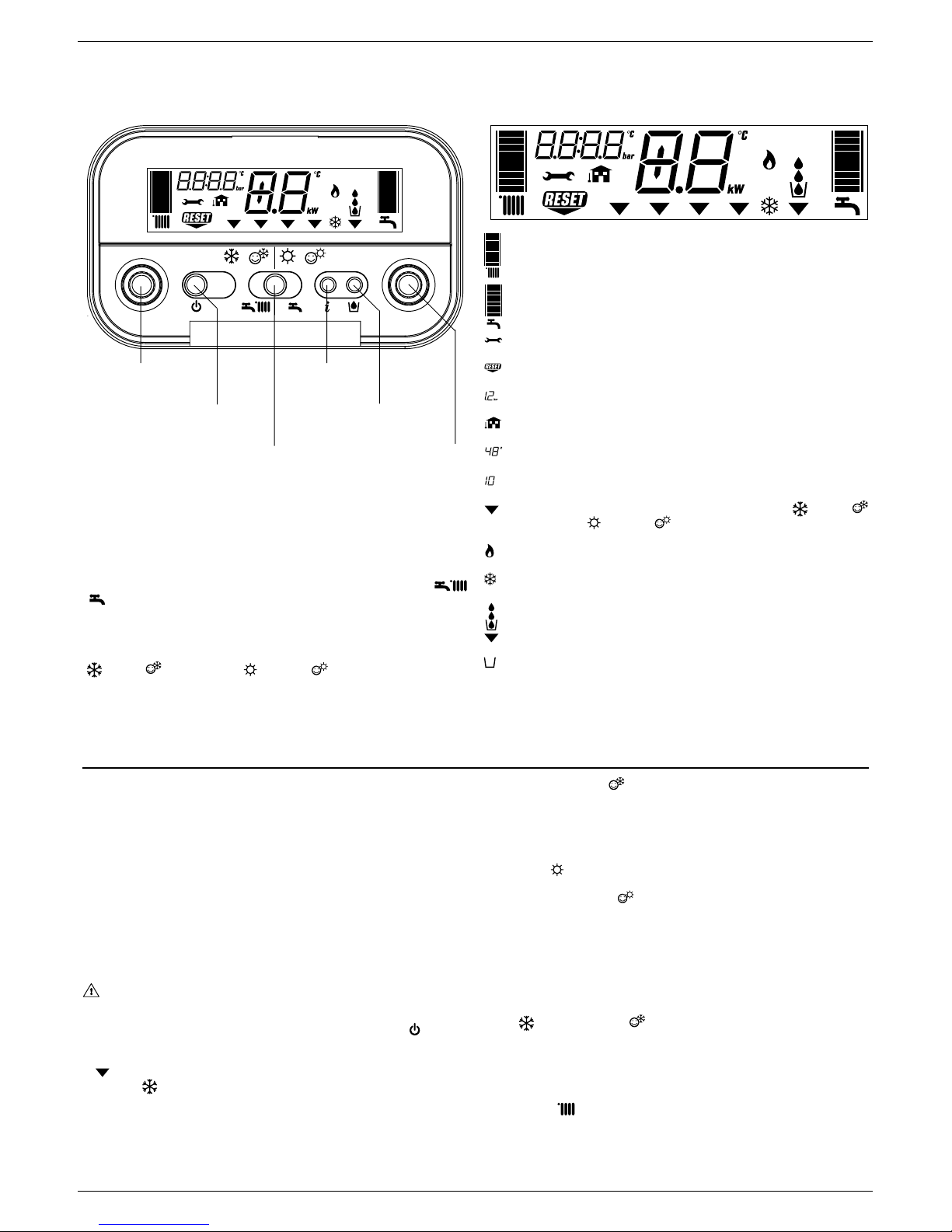
Heating water temperature selector: sets the heating water temperature.
Domestic hot water temperature selector: sets the domestic hot water tem-
perature.
Function key:
ON - the boiler is electrically powered and waiting for operating requests (
- )
OFF - the boiler is electrically powered but will not respond to operating requests
RESET - resets the boiler following a fault
Operating mode button: allows the most suitable operating mode to be selected
(
winter - winter comfort- summer - summer comfort).
Info button: shows a sequence of information concerning the operating status
of the machine.
Filling button: pushing it, the boiler automatically fills the system until the
pressure reaches 1 to 1.5 bar.
graduated heating water temperature scale with heating function symbol
graduated domestic hot water temperature scale with domestic hot water
function symbol
fault symbol (for details, please see page 15)
reset symbol (for details, please see page 15)
pressure value
external sensor connection
heating/domestic hot water temperature
or
fault symbol (e.g. 10 - no flame)
function selector (turned to the chosen operating mode: winter winter comfort- summer - summer comfort)
burner operating symbol
anti-freeze function active symbol
system filling function symbol
fill symbol
12 - START-UP AND OPERATION (GREEN C.S.I.)
The boiler produces heating and domestic hot water. The control panel contains the main boiler control and management functions.
Description of commands Description of display symbols
Switching on
Switch on the boiler as follows:
- access the gas tap through the slots in the cover located in the lower part of
the boiler
- open the gas tap by turning it anti-clockwise (
Fig. 1)
- power the boiler.
When powered, the boiler performs a test sequence and a series of numbers
and letters are shown on the display.
If the test is successful the boiler is ready to work about 4 seconds after the
cycle ends.
The display will look like
Fig. 2.
If the test is unsuccessful, the boiler will not work and a “0” will flash on the
display.
In this case, contact the Technical Assistance Centre.
The boiler turns on in the status it was in before it was switched off: if the
boiler was in the winter comfort mode when it was switched off, it will turn
on again in the winter comfort mode. If it was in the OFF mode, the display
will show two segments in the central area (
Fig. 3). Press the
button to
enable operation.
- press the function selector until the indicator moves to the required function
, depending on the kind of operation chosen.
- WINTER
: with the selector in this position, the heating water and domestic
hot water functions are activated.
In this position the S.A.R.A. function is enabled in the heating mode (see
chapter “Boiler functions”). The boiler actives the temperature stabiliser in
order to ensure the continuous production of domestic hot water, even for
small demands or when the inlet water is already hot. This prevents temperature oscillations due to the burner switching off/on.
- WINTER COMFORT
: with the selector in this position, as well as the
traditional function of heating water and domestic hot water, the preheating
function is also activated which keeps the water in the domestic hot water
exchanger hot in order to reduce waiting times. The S.A.R.A. Booster and
Domestic hot water preheating functions are enabled in this position (see
chapter “Boiler functions”).
- SUMMER
: with the selector in this position, just the traditional domestic
hot water function is activated.
- SUMMER COMFORT
: with the selector in this position, the boiler
provides just domestic hot water with a temperature stabiliser for small
deliveries. Ideal at the times of year or in the areas where the mains water is
already warm. In these conditions, the temperature of the hot water produced
by a boiler with just traditional functions (see SUMMER and WINTER COMFORT) may be instable.
Adjusting heating water temperature
Turning the selector A (
Fig. 4), after having positioned the selector mode on
winter or winter comfort , it is possible to regulate the heating water
temperature.
Turn clockwise to increase the temperature and anticlockwise to decrease.
The bar segments light up (every 5°C) as the temperature is increased. The
selected temperature value appears on the display. If you enter the S.A.R.A.
adjustment field (from 55 to 65°C) while selecting the heating water temperatu-
re, the symbol
and the graduated scale start flashing. For details about the
S.A.R.A. function, read page 12. The selected temperature value appears on
the display.
Domestic hot water
temperature selector
Operating mode button
ON-OFF-RESET
function selector
Filling button
Heating water circuit
temperature selector
INFO button
Page 10

10
EXCLUSIVE GREEN C.S.I. - R.S.I.
Open position
1
2
3
4
A
+4/5˚C
+3˚C
+2˚C
+1˚C
0˚C
-1˚C
-2˚C
-3˚C
-4/5˚C
5
6
7
B
8
9
10
Tap closed
11
12
13
Page 11
11
ENGLISH
14
15
17
16
18
19
20
21
22
Adjusting heating water temperature with an external sensor
connected
When an external probe is connected, the value of the delivery temperature is
automatically chosen by the system which rapidly adjusts ambient temperature
to the changes in external temperature. Just the central segment of the bar is
illuminated (
Fig. 5).
To increase or decrease the temperature with respect to the value automatically
calculated by the electronic board, turn the heating water selector clockwise to
increase and anticlockwise to decrease. The bar segments light up (at every
comfort level), correction tolerance lies between - 5 and + 5 comfort levels (
Fig.
5). When choosing the level of comfort, the digit area of the display shows the
required level of comfort while the bar shows the matching segment (Fig. 6).
Adjusting domestic hot water temperature
To adjust domestic hot water temperature, turn switch B (
Fig. 7) clockwise to
increase and anticlockwise to decrease. The bar segments light up (every 3°C)
as the temperature is increased.
The selected temperature value appears on the display.
When choosing the temperature, both for heating and domestic hot water, the
display shows the value being selected. About 4 seconds after the selection
has been made, the modification is memorised and the display returns to the
delivery temperature read by the probe.
Working the boiler
Adjust the ambient thermostat to the required temperature (approx. 20°C). If
there is a demand for heating water, the boiler starts and the
symbol is shown
on the display (Fig. 8). The boiler will remain working until the set temperatures
are reached, after which it will go on stand-by. In the event of ignition or operating
faults, the boiler will perform a “safety stop”.
The flame symbol
will go out and the fault code and will be displayed
(Fig. 9). For a description of faults and how to reset them, consult chapter
“Troubleshooting”.
Switching off
Switching off for short periods
For brief absences press the
button to switch off the boiler. The display will
show two segments in the central area (Fig. 3). When the boiler remains powered
with the gas tap open, it is protected by the following systems:
- anti-freeze (
Fig. 10): when the temperature of the water in the boiler falls
below safety values, the circulator and the burner work at minimum power to
increase the water temperature to a safe value (35°C). The
symbol lights
up on the display.
- circulator anti-block: one operating cycle is performed every 24 hours.
Switching off for long periods
For prolonged absences press the
button to switch off the boiler (Fig. 3).
The display will show two segments in the central area. Turn the main switch to
“off”.
Turn off the gas tap under the boiler by turning it clockwise (
Fig. 11).
In this case, the anti-freeze and anti-block systems are disabled. Empty
the water circuit or suitably protect it with a good make of anti-freeze.
Drain the domestic hot water circuit.
Boiler functions
Semi-automatic filling
The boiler features a semi-automatic filling device which turns on by pressing
the
button when the corresponding symbol is shown on the display (Fig.
12).
If this condition occurs it means that the system is incorrectly pressurised though
the boiler will continue to work regularly. Press the circuit filling button
to
start-up the filling sequence.
Page 12

12
EXCLUSIVE GREEN C.S.I. - R.S.I.
Press the circuit filling button a second time to interrupt the filling sequence.
During filling, the drops of the circuit filling symbol
and the growing pressure
value appear on the display in a cascade sequence (Fig. 13).
After filling, the
symbol is displayed for a few moments and then turns off.
Note
During filling, the boiler does not perform other functions. For example, if there
is a request for domestic hot water, the boiler is unable to provide it until filling
has finished.
Note
If circuit pressure reaches 0.6 bar, the pressure value flashes on the display
(
Fig. 14); if it falls below a minimum safety value (0.3 bar), fault code 41 appears
on the display (Fig. 15) for a certain time, following which, if the fault persists,
fault code 40 is displayed (see chapter on “Troubleshooting”).
In the event of fault 40, press
to reset and then to start filling the circuit.
If you have to fill the system several times, contact the Technical Service Centre
to check whether the heating circuit is watertight (see if there are any leaks).
Information
Press
, the display turns off and just the word InFO appears (Fig. 16). Press
the button
to view operating information. Press the button again to move on to
the next piece of information. If the
button is not pressed, the system
automatically exits the function.
Info list:
Info 0 - shows the word InFO (Fig. 16)
Info 1 - only with the external probe connected, displays external temperature
(e.g. 12°C) (Fig. 17).
The values shown on the display range between - 30°C and 35°C.
Beyond these values the display shows “- -”.
Info 2 - shows circuit pressure (
Fig. 18)
Info 3 - shows the set heating temperature (Fig. 19)
Info 4 - shows the set domestic hot water temperature (
Fig. 20)
Info 5 - displays the set heating temperature, in reference to the second circuit,
only if it is connected.
S.A.R.A. function (
Fig. 21)
If the “winter” mode is selected, the S.A.R.A. (Automatic Ambient Adjustment
System) function can be activated.
Turn the heating water temperature selector to a temperature ranging between
55 and 65°C.
The S.A.R.A. self-adjustment system activates: depending on the temperature
set on the ambient thermostat and the time taken to reach it, the boiler
automatically adjusts the heating water temperature to reduce operating times,
thereby increasing operating comfort and energy saving.
S.A.R.A. BOOSTER function (
Fig. 22)
If the “winter comfort” mode is selected, the S.A.R.A. Booster function is activated
for the heating circuit and reaches the required ambient temperature more
quickly.
DOMESTIC HOT WATER PRE-HEATING function (
Fig. 22)
If the “winter comfort” mode is selected, the domestic hot water Preheating
function is enabled. This function sets out to keep the domestic hot water
contained in the boiler hot, thereby considerably reducing delivery waiting times.
The
function should be selected to reduce power consumption in areas
where the mains water is not particularly cold.
In this case, the Booster and Preheating functions are not activated.
INF2 (
Fig. 23)
It is possible to display information, which may be useful for the Technical
Assistance Centre, by pressing the button
for 10 seconds: the code “INF2”
appears on the display.
Step
1
2
3
4
5
6
7
8
9
10
11-18
Description
Input probe temperature
Return probe temperature
First sanitary probe temperature (*)
Not used in this model
Not used in this model
Second heating system probe temperature
Not used in this model
Ventilator speed /100
Not used in this model
Not used in this model
Historic alarm codes
Display
2 digits
xx
xx
xx
xx
xx
xx
xx
xx
xx
xx
xx
Display
4 digits
01
02
03
Cond
05
06
07
FAN
09
10
HIS0-HIS7
°C
°C
°C
°C
°C
Note (*): if the SAN probe is faulty or disconnected, in the place of the value “- -” is displayed.
INF2 list
23
Page 13

13
ENGLISH
graduated heating water temperature scale with heating function symbol
graduated domestic hot water temperature scale (shown in C case only)
domestic hot water function symbol (shown in B and C cases)
fault symbol (for details, please see page 22)
reset symbol (for details, please see page 22)
pressure value
external sensor connection
heating/domestic hot water temperature (shown in C case only)
or
fault symbol (e.g. 10 - no flame)
function selector (turned to the chosen operating mode: winter or
summer (only if water-tank connected)
burner operating symbol
anti-freeze function active symbol
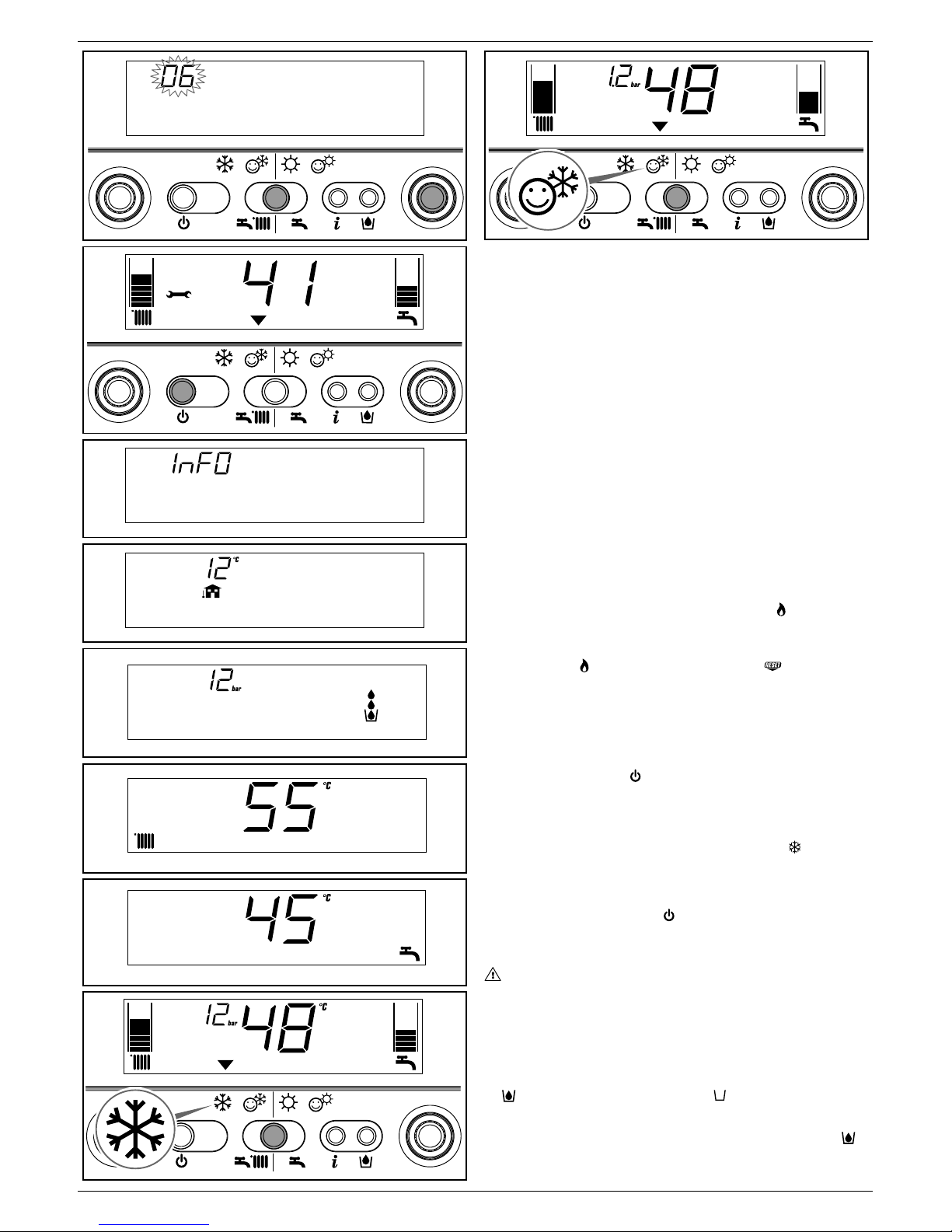
13 - START-UP AND OPERATION (GREEN R.S.I.)
This boiler is able to operate in different conditions:
CASE A - only heating
CASE B - only heating with external water tank connected, managed by a thermostat, to prepare domestic hot water
CASE C - only heating with external water tank connected, managed by a temperature sensor (kit available upon request), to prepare domestic hot water.
Depending on the type of installation selected, it is necessary to set the parameter “domestic hot water mode”. This operation must be performed by a Technical
Service Centre when starting-up the boiler.
Description of commands Description of display symbols
Heating water temperature selector: sets the heating water temperature.
Domestic hot water temperature selector (C case only): sets the
domestic hot water temperature storaged in the water tank.
Setting parameters selector (cases A, B and C): using in calibration and
programmation phase.
Function key:
ON - the boiler is electrically powered and waiting for operating requests
(
- )
OFF - the boiler is electrically powered but will not respond to operating
requests
RESET - resets the boiler following a fault
Operating mode button:
button allows to choose the desired
operating mode: pressing it, the indicator “function selector”
moves to:
(winter) or (summer, only if water-tank connected).
Info button: shows a sequence of information concerning the operating
status of the machine.
Switching on
Switch on the boiler as follows:
- access the gas tap through the slots in the cover located in the lower part of
the boiler
- open the gas tap by turning it anti-clockwise (
Fig. 1)
- power the boiler.
When powered, the boiler performs a test sequence and a series of numbers
and letters are shown on the display.
If the test is successful the boiler is ready to work about 4 seconds after the
cycle ends.
The display will look like
Fig. 2.
If the test is unsuccessful, the boiler will not work and a “0” will flash on the
display.
In this case, contact the Technical Assistance Centre.
The boiler turns on in the status it was in before it was switched off: if the
boiler was in the winter mode when it was switched off, it will turn on again
in the winter mode. If it was in the OFF mode, the display will show two
segments in the central area (
Fig. 3). Press the
button to enable
operation.
Choose the desired operating mode by pressing
button, until the
symbol moves to:
WINTER
SUMMER
WINTER function (Fig. 4)
With the selector in this position, the boiler provides hot water for the heating
and, if an external water tank is connected, provides water to the water tank to
allow domestic hot water preparation. Function S.A.R.A Booster is enabled in
this position (see chapter “Boiler functions”).
SUMMER function (only with external water tank connected,
Fig. 5)
With the selector in this position, the boiler provides water to the water tank with
a temperature stabiliser to allow domestic hot water preparation.
Adjusting heating water temperature
Turning the selector A (
Fig. 6), after having positioned the selector mode on
winter
, it is possible to regulate the heating water temperature.
Turn clockwise to increase the temperature and anticlockwise to decrease.
Setting parameters
selector
Operating mode button
ON-OFF-RESET
function selector
Domestic hot water
temperature selector
(C case only)
Heating water circuit
temperature selector
INFO button
Page 14

14
EXCLUSIVE GREEN C.S.I. - R.S.I.
Open position
1
2
3
4
5
6
A
+4/5˚C
+3˚C
+2˚C
+1˚C
0˚C
-1˚C
-2˚C
-3˚C
-4/5˚C
7
9
D
11
10
8
Page 15

15
ENGLISH
12
Tap closed
13
14
15
16
18
17
20
21
19
22
The bar segments light up (every 5°C) as the temperature is increased. The
selected temperature value appears on the display.
Adjusting heating water temperature with an external sensor
connected
When an external probe is connected, the value of the delivery temperature is
automatically chosen by the system which rapidly adjusts ambient temperature
to the changes in external temperature. Just the central segment of the bar is
illuminated (
Fig. 7).
To increase or decrease the temperature with respect to the value automatically
calculated by the electronic board, turn the heating water selector clockwise to
increase and anticlockwise to decrease. The bar segments light up (at every
comfort level), correction tolerance lies between - 5 and + 5 comfort levels (
Fig.
7). When choosing the level of comfort, the digit area of the display shows the
required level of comfort while the bar shows the matching segment (Fig. 8).
Adjusting domestic hot water temperature
CASE A - only heating - adjusting not applicable
CASE B - only heating + water tank with thermostat: in this condition every time
there is a request from the water tank thermostat, the boiler supplies hot water
to preparing domestic hot water. During this operation on the display the icon
flashed.
CASE C - only heating + water tank with sensor: to adjust domestic hot water
temperature storaged in the water tank, turn switch D (Fig. 9): clocwise to
increase and anticlockwise to decrease. The bar segments light up (every 3°C)
as the temperature is increased. About 4 seconds after the selection has been
made, the modification is memorised and the display returns to the delivery
temperature read by the sensor.
Working the boiler
Adjust the ambient thermostat to the required temperature (approx. 20°C). If
there is a demand for heating water, the boiler starts and the
symbol is shown
on the display (Fig. 10). The boiler will remain working until the set temperatures
are reached, after which it will go on stand-by. In the event of ignition or operating
faults, the boiler will perform a “safety stop”.
The flame symbol
will go out and the fault code and will be displayed
(Fig. 11). For a description of faults and how to reset them, consult chapter
“Troubleshooting”.
Switching off
Switching off for short periods
For brief absences press the
button to switch off the boiler. The display will
show two segments in the central area (Fig. 12). When the boiler remains
powered with the gas tap open, it is protected by the following systems:
- anti-freeze (
Fig. 3): when the temperature of the water in the boiler falls below
safety values, the circulator and the burner work at minimum power to increase
the water temperature to a safe value (35°C). The
symbol lights up on the
display.
- circulator anti-block: one operating cycle is performed every 24 hours.
Page 16

16
EXCLUSIVE GREEN C.S.I. - R.S.I.
Switching off for long periods
For prolonged absences press the
button to switch off the boiler (Fig. 3).
The display will show two segments in the central area. Turn the main switch to
“off”.
Turn off the gas tap under the boiler by turning it clockwise (
Fig. 13).
In this case, the anti-freeze and anti-block systems are disabled. Empty
the water circuit or suitably protect it with a good make of anti-freeze.
Boiler functions
Filling the circuit
If circuit pressure reaches 0.6 bar, the pressure value flashes on the display
(Fig. 14); if it falls below a minimum safety value (0.3 bar), fault code 41 appears
on the display (Fig. 15) for a certain time, following which, if the fault persists,
fault code 40 is displayed (see chapter on “Troubleshooting”).
In the event of faul 40 (
Fig. 16) proceed as follow to restore the correct pressure
value:
- press
button
- open the filling tap external to the boiler, until the pressure shown in the
display is between 1 and 1,5 bar.
If you have to fill the system several times, contact the Technical Service Centre
to check whether the heating circuit is watertight (see if there are any leaks).
Information
Press
, the display turns off and just the word InFO appears (Fig. 17). Press
the button
to view operating information. Press the button again to move on to
the next piece of information. If the button is not pressed, the system
automatically exits the function.
Info list:
Info 0 - shows the word InFO (
Fig. 17)
Info 1 - only with the external probe connected, displays external temperature
(e.g. 12°C) (Fig. 18). The values shown on the display range between - 30°C
and 35°C. Beyond these values the display shows “- -”
Info 2 - shows circuit pressure (
Fig. 19)
Info 3 - shows the set heating temperature (Fig. 20)
Info 4 - shows the setted temperature (only water tank with sensor, Fig. 21)
Info 5 - displays the set heating temperature, in reference to the second circuit,
only if it is connected.
S.A.R.A. BOOSTER function (
Fig. 22)
If the “winter” mode is selected, the S.A.R.A. Booster function is activated for
the heating circuit. This function allows to reach the required ambient temperature more quickly.
Depending on the temperature set on the ambient thermostat and the time taken
to reach it, the boiler automatically adjusts the heating water temperature to
reduce operating times, thereby increasing operating comfort and energy saving.
INF2 (
Fig. 23)
It is possible to display information, which may be useful for the Technical
Assistance Centre, by pressing the button
for 10 seconds: the code “INF2”
appears on the display.
Step
1
2
3
4
5
6
7
8
9
10
11-18
Description
Input probe temperature
Return probe temperature
Sanitary probe temperature:
water tank with thermostat (A and B cases)
water tank with probe (C case)
Not used in this model
Not used in this model
Second heating system probe temperature
Not used in this model
Ventilator speed /100
Not used in this model
Not used in this model
Historic alarm codes
Display
2 digits
xx
xx
-xx
xx
xx
xx
xx
xx
xx
xx
xx
Display
4 digits
01
02
03
03
Cond
05
06
07
FAN
09
10
HIS0-HIS7
°C
°C
°C
°C
°C
°C
INF2 list
23
Page 17

17
ENGLISH
FAULT
FLAME FAILURE BLOCK (D)
PARASITE FLAME (T)
RE-ATTEMPT IN PROGRESS (T)
MINIMUM GAS INPUT PRESSURE (T)
MINIMUM GAS INPUT PRESSURE (D)
FLAME PRESENT IN STAND-BY FOR NO REASON (D)
LIMIT THERMOSTAT/FUME THERMOSTAT (D)
SHORT CIRCUIT FUMES PROBE (D)
MAXIMUM TEMPERATURE FUMES PROBE (D)
MAXIMUM TEMPERATURE INPUT PROBE (D)
MAXIMUM TEMPERATURE INPUT PROBE (T)
MAXIMUM TEMPERATURE RETURN PROBE (D)
MAXIMUM TEMPERATURE RETURN PROBE (T)
RETURN-INPUT PROBE DIFFERENTIAL (D)
FUMES PROBE OPEN (D)
FUMES OUTLET OR AIR PRESSURE SWITCH (cycle start) (D)
FUMES OUTLET OR AIR PRESSURE SWITCH (cycle start) (T)
VENTILATOR IN CYCLE (low number of revolutions) (D)
VENTILATOR (cycle start) (D)
VENTILATOR (cycle end) (T)
FUMES OUTLET OR AIR PRESSURE SWITCH (in cycle) (T)
VENTILATOR IN CYCLE (high number of revolutions) (D)
FUMES OUTLET OR AIR PRESSURE SWITCH (in cycle) (D)
INSUFFICIENT SYSTEM PRESSURE (D*)
INSUFFICIENT SYSTEM PRESSURE (T*)
WATER PRESSURE TRANSDUCER (D)
ELECTRONIC BOARD (D)
SANITARY PROBE 1 (T°)
SHORT CIRCUIT/OPEN PRIMARY PROBE (D)
MAXIMUM TEMPERATURE INPUT PROBE (T)
SHORT CIRCUIT/OPEN RETURN PROBE (D)
LOW TEMPERATURE THERMOSTAT (T)
INPUT/RETURN DIFFERENTIAL (T)
INPUT/RETURN DIFFERENTIAL (D)
SYSTEM ANOMALY (D )
SYSTEM ANOMALY (T)
SYSTEM ANOMALY (D )
SYSTEM ANOMALY (T)
CONDENSATE OR CONDENSATE SENSOR (D)
CONDENSATE OR CONDENSATE SENSOR (T)
CONDENSATE SENSOR OR OPEN CIRCUIT (D)
CONDENSATE SENSOR OR OPEN CIRCUIT (T)
Alarm ID
10
11
12
13
14
15
20
21
22
24
25
26
27
28
29
30
31
33
34
35
36
37
38
40
41
42
50-59
60
70
71
72
77
78
79
80
81
82
83
92
93
94
95
Symbol
YES
NO
NO
NO
YES
YES
YES
YES
YES
YES
NO
YES
NO
YES
YES
YES
NO
YES
YES
NO
NO
YES
YES
YES
NO
YES
YES
NO
YES
NO
YES
NO
NO
YES
YES
NO
YES
NO
YES
NO
YES
NO
Symbol
NO
YES
NO
YES
NO
YES
NO
YES
NO
NO
YES
NO
YES
YES
YES
NO
YES
YES
NO
YES
YES
YES
YES
NO
YES
YES
YES
YES
YES
NO
YES
YES
YES
NO
YES
YES
YES
YES
NO
YES
YES
YES
14 - TROUBLESHOOTING
When a fault appears on the display, the flame symbol goes out, a flashing code is shown and the two symbols and appear either together or separately.
For a description of the faults, consult the following table.
(D) - Permanent - (T) - Temporary. In this operating status the boiler attempts to eliminate the fault on its own
(°) C.S.I. - Fault in domestic hot water circuit sensor - 60: the boiler works regularly but does not ensure the stability of the hot water temperature which, however,
is delivered at a temperature of approximately 50°C. The fault code is only displayed in standby. R.S.I. - Only with external water tank with sensor. The fault
code is shown when the boiler is in stand-by.
(*) If these two errors occur, check the pressure indicated on the water gauge. If the pressure is insufficient (< 0,4 bar, red area), proceed with the filling
operations described in the chapter “Filling and emptying the systems”. If the system’s pressure is sufficient (> 0,6 bar, blue area) the malfunction is caused
by a lack of water circulation. Contact the Technical Assistance.
Resetting faults
Wait for about 10 seconds before resetting operating conditions.
Then proceed as follows:
1) Viewing just the
symbol
If
disappears, it means that an operating fault has been discovered which
the boiler is attempting to solve on its own (temporary stoppage). If the boiler
does not resume normal operation, two things may happen:
Case A (
Fig. A)
disappears, the symbol and a different alarm code appear. In this case,
proceed as described in point 2.
Case B (
Fig. B)
and a different alarm code are displayed together with .
In this case, proceed as described in point 3.
2) Viewing just the
symbol (Fig. C)
Press the
button to reset the appliance. If the boiler starts the ignition phase
and resumes normal operation, it may have stopped by accident.
If these stoppages should continue, contact the Technical Assistance Centre.
3) Viewing the
and symbols (Fig. D)
Contact the Technical Assistance Centre.
Note (C.S.I.)
Fault in domestic hot water circuit sensor - 60: the boiler works regularly but
does not ensure the stability of the hot water temperature which, however, is
delivered at a temperature of approximately 50°C. The fault code is only displayed
in standby.
C.S.I.
R.S.I.
C.S.I.
R.S.I.
A
Temporary
fault
Permanent
fault
Page 18

18
EXCLUSIVE GREEN C.S.I. - R.S.I.
C.S.I.
R.S.I.
C.S.I.
R.S.I.
B
Temporary
fault
Permanent
fault
C.S.I.
R.S.I.
C
C.S.I.
R.S.I.
D
15 - PROGRAMMING PARAMETERS
This boiler incorporates a new generation of electronic boards that, by setting/
modifying operating parameters, allow the boiler to be personalised to satisfy
various system and/or user requirements. The programmable parameters are
shown in the table on the next page.
The parameters must be programmed with the boiler in the OFF position.
To do this, press the
button until the display shows “- -” (Fig. E).
During parameter modification operations, the “select functions” button
acts as an ENTER (confirm) button, the
button acts as an ESCAPE
(escape) button. If no confirmation is given within 10 seconds, the value is
discarded and returns to the previously set one.
Setting the password
Press and hold down the select functions button and the
button together for
about 10 seconds. The display will look like Fig. F. Enter the password for
accessing the parameter modifications function by turning the domestic hot
water temperature selector to obtain the required value. The password for
accessing the parameter programming function is located on the back side of
the control panel. Confirm by pressing ENTER.
Modifying parameters
Turn the domestic hot water temperature selector (
Fig. G) to sequentially scroll
the two-figure codes of the parameters indicated in the table. After identifying
the parameter you wish to modify, proceed as follows:
- press ENTER to access the parameter modification function. When ENTER
is pressed, the previously set value starts flashing (
Fig.H)
- turn the domestic hot water temperature selector to change the value
- press ENTER to confirm the new value. The digits stop flashing (Fig.I)
- press ESCAPE to exit.
The boiler returns to the “- -” (OFF) status.
To reset, press the
button (Fig. E).
G
C.S.I.
R.S.I.
E
C.S.I.
R.S.I.
F
C.S.I.
R.S.I.
ENTER ESCAPE
Page 19

19
ENGLISH
C.S.I.
R.S.I.
I
C.S.I.
R.S.I.
Parameter value
Parameter number
H
PROGRAMMABLE PARAMETERS
PARAMETERS DESCRIPTION
GAS TYPE
BOILER POWER
INSULATION LEVEL OF BUILDING
DHW MODE
DHW CIRCUIT MAXIMUM SET-POINT
(C.S.I.)
WATER TANK MAXIMUM SET-POINT (R.S.I.)
DELIVERY TERMPERATURE EXTERNAL WATER TANK (R.S.I.)
DELTA EXTERNAL WATER TANK (ON) (R.S.I.)
HEATING MODE
HEATING CIRCUIT MAXIMUM SET-POINT
MINIMUM HEATING SET POINT
MAXIMUM HEATING VENTILATOR SPEED
MINIMUM HEATING VENTILATOR SPEED
DIFFERENTIAL HEATING POSITIVE
DIFFERENTIAL HEATING NEGATIVE
MAX HEATING POWER REDUCTION TIMER
FORCED HEATING SHUT DOWN TIMER
HEATING TIMER RESET FUNCTION
MAXIMUM HEATING SET POINT 2CH (II circuit)
MINIMUM HEATING SET POINT 2CH (II circuit)
DHW THERMOSTAT OPERATING MODE
(C.S.I.)
DHW PREHEATING FUNCTION (C.S.I.)
S.A.R.A. FUNCTION (C.S.I.)
S.A.R.A. BOOSTER FUNCTION
THERMOREGULATION FUNCTION
INCLINATION THERMOREGULATION CURVE (OTC)
THERMOREGULATION FUNCTION 2CH
INCLINATION THERMOREGULATION CURVE (OTC) 2CH
THIS PARAMETER IS NOT USED ON THIS MODEL. DO NOT MODIFY
THIS PARAMETER IS NOT USED ON THIS MODEL. DO NOT MODIFY
HEAT REQUEST TYPE CH1 (I circuit)
HEAT REQUEST TYPE CH2 (II circuit)
DHW ANTIFREEZE FUNCTION TEMPERATURE (ON)
HEATING ANTIFREEZE FUNC. DELIVERY TEMP. (ON)
THIS PARAMETER IS NOT USED ON THIS MODEL. DO NOT MODIFY
EXTERNAL SENSOR REACTIVITY
SEMI-AUTOMATIC FILLING
AUTOMATIC FILLING PRESSURE (ON)
N.
PAR.
1
2
3
10
11
12
13
14
20
21
22
23
24
25
26
28
29
30
31
32
40
41
42
43
44
45
46
47
48
50
51
52
61
62
63
65
85
86
DEFAULT
(1)
1
16*-26-34
5
1
60
60
80
5
1
80
20
MAX
MIN
6
6
15
5
0
80
20
1
1
1
1
1
20
1
20
0
1
0
0
4
6
6
255
1
0.6
PARAMETERS
(2)
0 - OFF
1 - Instantaneous
2 - Mini-tank
3 - External water- tank with thermostat
4 - External water- tank with sensor
UNIT OF
MEASURE
min
°C
°C
°C
°C
°C
°C
revs/min
revs/min
°C
°C
min
min
°C
°C
-
-
-
°C
°C
bar
MIN
1
Methane
2 LPG
3 Methane France
5
40
40
50
40
20
36 (3.600
(4)
)
2
2
0
0
0 (NO)
40
20
0 - OFF
1 - AUTO
2 - ON
0 - OFF
1 - AUTO
2 - ON
0 - OFF
1 - AUTO
0 - OFF
1 - AUTO
0 - OFF
1 - AUTO
2,5
0 - OFF
1 - AUTO
2,5
0
0
0
0
0 (
very slow)
0 - Disabled
1 - Enabled
0.4
MAX
20
60
80
85
10
80
39
36 (3.600
(4)
)
10
10
20
20
1 (YES)
80
39
40
40
1
1
10
10
255 (
very slow)
1.0
0 - OFF
1 - ON
2 - Zone valves + remote control panel
3 - CONNECT AP
4 -
Not used
5 - Not used
6 - CONNECT AT/BT
G20 G31
16 kW* 48 48
25 kW 49 51
35 kW 60 60
G20 G31
16 kW* 14 14
25 kW 14 14
35 kW 14 14
10
(3)
-16-20
(3)
-26-30-34-50
(3)
-70
(3)
* R.S.I. only (1) Setted in factory.
(2) Setted by technical assistance centre.
(3) Power not available at the moment.
(4) The value is expressed on the display in revs/min/100 (example 3.600 = 36).
Page 20

20
EXCLUSIVE GREEN C.S.I. - R.S.I.
To access the programming mode, consult “Programming parameters”.
PARAMETER 03. Type of building
In order to calculate delivery temperature, the temperature control system does
not directly use the external temperature value but considers the heat insulation
of the building: in well-lagged buildings, external temperature variations affect
the ambient temperature less than they do in badly-lagged buildings. Use
parameter 3 to set the heat insulation level of the building according to the
following scheme:
PARAMETERS 21 and 22. Maximum and minimum delivery
temperature
These two parameters limit the delivery temperature automatically produced by
the TEMPERATURE CONTROL function. PARAMETER 21 determines
MAXIMUM DELIVERY TEMPERATURE (MAXIMUM HEATING SET POINT)
while PARAMETER 22 determines MINIMUM DELIVERY TEMPERATURE
(MINIMUM HEATING SET POINT).
PARAMETER 44. Enable thermoregulation function
The connected external temperature probe combined with PARAMETER 44
provides the following operating modes:
EXTERNAL PROBE CONNECTED and PARAMETER 44 = 0 (OFF) in this
case the TEMPERATURE CONTROL function is disabled even though the
external probe is connected. The temperature read by the external probe can
always be viewed by pressing the INFO button. The TEMPERATURE
CONTROL symbols are not displayed.
EXTERNAL PROBE CONNECTED, PARAMETER 44 = 1 (ON) in this case
the TEMPERATURE CONTROL function is enabled. The temperature read by
the external probe and the TEMPERATURE CONTROL symbols can be viewed
by pressing the INFO button.
The TEMPERATURE CONTROL function cannot be enabled unless the
external probe has been fitted and connected. In this case, PARAMETER
44 is ignored and has no effect on boiler operation.
PARAMETER 45. Choosing the offset temperature curve (graph 1)
The offset heating curve maintains a theoretical ambient temperature of 20°C
at external temperatures ranging from +20°C to -20°C. The choice of the curve
depends on the rated minimum external temperature (on the geographical area,
therefore) and the rated delivery temperature (on the type of system, therefore)
and must be carefully calculated by the fitter using the following formula:
If, from your calculations, you obtain an intermediate value between two curves,
we suggest choosing the compensation curve closest to the value obtained.
Example: if the value obtained from the calculations is 8, this is between curve
7.5 and curve 10. In this case, choose the closest curve, which is 7.5.
PARAMETER 51. Type of heat request
IF AN AMBIENT THERMOSTAT IS CONNECTED TO THE BOILER, SET
PARAMETER 51 = 0 (graph 2).
The ambient thermostat makes a heat request when its contact closes, while it
stops it when its contact opens. Though delivery temperature is automatically
calculated by the boiler, the user may manually override it. By modifying
HEATING on the user interface, the HEATING SET POINT will no longer be
available but just a value that can be set from +5 to -5°C as required. Modifications
to this value do not directly change delivery temperature but affect the calculation
made to automatically determine its value by modifying the reference temperature of the system (0 = 20°C).
For boilers fitted with the S.A.R.A. BOOSTER function, if the AMBIENT
THERMOSTAT remains closed for a long time, the boiler automatically increases
the delivery temperature which is added to the effect of the temperature control
function. When the AMBIENT THERMOSTAT opens, the boiler automatically
returns to the value determined by the TEMPERATURE CONTROL function.
IF A PROGRAMMABLE TIMER IS CONNECTED TO THE BOILER, SET
PARAMETER 51 = 1 (graph 3).
When the contact is closed, the heat request is made by the delivery probe on
the basis of the external temperature in order to maintain the rated ambient
temperature at the DAY level (20°C). When the contact opens, it does not stop
the heat request but reduces (parallel shift) the temperature curve to the NIGHT
level (16°C). Though delivery temperature is automatically calculated by the
boiler, the user may manually override it.
By modifying HEATING on the user interface, the HEATING SET POINT will
no longer be available but just a value that can be set from +5 to –5°C as
required.
Modifications to this value do not directly change delivery temperature but affect
the calculation made to automatically determine its value by modifying the
reference temperature of the system (0 = 20°C for DAY level; 16°C for NIGHT
level).
CONNECT AT/BT
In case of using CONNECT AT/BT, accessory supplied on request, the boiler
gives the possibility to choose 2 thermoregulation curves:
- OTC 1 CH (parameter 45) for a direct system
- OTC 2 CH (parameter 47) for a mixed system.
Even in case of second circuit (2CH) the curve depends on the external minimum
project temperature (on the geographical area, therefore) and on the delivey
project temperature (on the type of system, therefore); the installer must to put
attention to calculate it using the following formula:
3
21
22
44
45
51
PARAMETER
TYPE OF BUILDING
MAXIMUM HEATING SET POINT
MINIMUM HEATING SET POINT
ENABLE THERMOREGULATION FUNCTION
OFFSET TEMPERATURE CURVE
TYPE OF HEAT REQUEST
AVAILABLE IN THE PROGRAMMING MODE
INSTALLATION AND CALIBRATION & SERVICE
INSTALLATION
INSTALLATION
INSTALLATION
INSTALLATION AND CALIBRATION & SERVICE
INSTALLATION
New
houses
A
B
C
D
Old
houses
19
20
19
18
Hollow
bricks
14
16
15
12
Solid
bricks
12
15
14
10
Stones
8
11
9
5
16 - SETTING THE THERMOREGULATION
Checking the connection with the external probe
After connecting the external probe to the boiler, use the INFO function to check that the probe has been automatically recognised by the temperature control card.
Immediately after installation, the value read by the probe may very well be higher then that measured by a reference probe.
Enable and optimise the THERMOREGULATION function by setting the following parameters:
Type of building
D
C
B
A
rated delivery T - 20
P. 45 = 10 x
20- rated min. external T
rated delivery T - 20
P. 47 = 10 x
20- rated min. external T
Parameters 31 and 32 give the possibility to define the maximum and the
minimum central heating set-point of the second circuit.
To correct the curve in this configuration, please refer to the instructions supplied
with the accessory.
Page 21

21
ENGLISH
Condensing boiler
Gas type
Gas
category
17 - SERIAL NUMBER PLATE
DHW operation
CH operation
Qn nominal capacity
Pn nominal power
IP protection level
P. min minimum pressure
Pmw DHW maximum pressure
Pms CH maximum pressure
T temperature
ηη
ηη
η working efficiency
D specific capacity
NOx NOx value class
18 - ADJUSTMENTS
The boiler has already been factory adjusted by the manufacturer. If a new
adjustment is required, for example, after extraordinary maintenance, replacing
the gas valve or converting from natural gas to LPG, proceed as follows.
Maximum and minimum power, minimum and maximum heating,
must be adjusted in the indicated sequence by qualified staff.
- Unscrew the lower cover fixing screw (C, Fig. 1.4)
- Pull the cover towards you and remove (A-B) (
Fig. 1.5)
- Loosen the two fixing screws (D) and remove the shell (Fig. 1.2)
- Lift up the panel and turn it forwards
- Loosen the pressure tap screw downline from the gas valve by about two
turns and connect the pressure gauge to it
CALIBRATION & SERVICE operations must be performed with the boiler
in the OFF position. To do this, press the
button until the display shows
“- -” (Fig. E).
During parameter modification operations, the “select functions” button
acts as an ENTER (confirm) button, the
button acts as an ESCAPE
button. If no confirmation is given within 10 seconds, the value is discarded
and returns to the previously set one.
Setting the password
Press and hold down the operating mode button and the
button together for
about 10 seconds. The display will look like Fig. F.
Enter the password for accessing the parameter modifications function by turning
the domestic hot water temperature selector to the required value.
The password is located on the back side of the control panel. Confirm by
pressing ENTER.
Calibration phases
Turn the domestic hot water selector to sequentially scroll the CALIBRATION
& SERVICE phases:
1 gas type
2 boiler power (do not modify this parameter)
10 domestic hot water mode (do not modify this parameter)
3 insulation level of building (only if external sensor is connected)
45 inclination of thermoregulation curve (OTC), only if external sensor is
connected)
47 inclination of thermoregulation curve 2CH (OTC), only if external sensor is
connected)
HP maximum fan speed (do not modify this parameter)
LP minimum fan speed (do not modify this parameter)
SP ignition speed (do not modify this parameter)
HH boiler at maximum power
LL boiler at minimum power
MM fan ignition speed (do not modify this parameter)
23 maximum heating adjustment possibility
24 minimum heating adjustment possibility.
The parameters 2 - 10 - HP - SP - LP - MM - 23 - 24 must be modified,
by professionally qualified personnel, only if absolutely necessary.
The manufacturer refuses any responsibility in the case of incorrect
setting of the parameters.
20
20
30
40
50
60
70
80
90
100
15 10 5 0 -5 -10 -15 -20
P.22
2,5
5
7,5
10
P.21
15
17,5
20
22,52527,530
32,5
35
37,5
40
12,5
GRAPH 1
Thermoregulation curves
EXTERNAL TEMPERATURE (°C)
P21 = MAXIMUM HEATING SET POINT
P22 = MINIMUM HEATING SET POINT
DELIVERY TEMPERATURE (°C)
10
20
30
40
50
60
70
80
90
-20-15-10-505101520
GRAPH 3
Parallel night reduction
DELIVERY TEMPERATURE (°C)
EXTERNAL TEMPERATURE (°C)
DAY
temperature curve
NIGHT
temperature curve
0˚C
+5˚C
-5˚C
10
20
30
40
50
60
70
80
90
-20-15-10-5051015202530
GRAPH 2
Temperature curve correction
DELIVERY TEMPERATURE (°C)
EXTERNAL TEMPERATURE (°C)
Page 22

22
EXCLUSIVE GREEN C.S.I. - R.S.I.
Table 1
MAXIMUM NUMBER OF FAN REVOLUTIONS
16 R.S.I.
25 C.S.I.-R.S.I.
35 C.S.I.-R.S.I.
rpm
rpm
rpm
G20
48
49
60
G31
48
51
60
Table 2
MINIMUM NUMBER OF FAN REVOLUTIONS
16 R.S.I.
25 C.S.I.-R.S.I.
35 C.S.I.-R.S.I.
rpm
rpm
rpm
G20
14
14
14
G31
14
14
14
Table 3
16 R.S.I. - CO2 max
25 C.S.I.-R.S.I. - CO
2 max
35 C.S.I.-R.S.I. - CO
2 max
%
%
%
G20
8,8
9,0
9,0
G31
10,0
10,0
10,0
Table 4
16 R.S.I. - CO2 min
25 C.S.I.-R.S.I. - CO
2 min
35 C.S.I.-R.S.I. - CO
2 min
%
%
%
G20
8,8
9,3
9,0
G31
10,0
10,3
10,0
GAS TYPE (P. 1)
Modify the set value as follows:
- press ENTER to access the parameter modification function. When ENTER
is pressed, the previously set value starts flashing (Fig. H)
- turn the domestic hot water temperature selector to change the value (1 MTN
- 2 LPG)
- press ENTER to confirm the new value. The digits stop flashing.
BOILER POWER (P. 2)
To modify the boiler power:
- select parameter 02
- press the ENTER button to access the parameter value modification function.
As the ENTER button is pressed, the digits flash, highlighting the previously
set value
- turn the sanitary water temperature selector in order to adjust the value to the
desired number: 26 (25 kW) and 34 (35kW) for GREEN C.S.I.; 16 (16kW),
26 (25 kW) and 34 (35kW) for GREEN R.S.I.
- confirm the new value you have set by pressing ENTER. The digits stop
flashing.
It is absolutely forbidden to set different gas types and/or boiler powers
from those indicated on the registration plate.
The manufacturer refuses any responsibility if the 2 parameters are set at
different values compared to those indicated on the registration plate.
MAXIMUM VENTILATOR SPEED (P. HP)
- Select parameter HP
- Press the ENTER button, then modify the value of the parameter by turning
the sanitary water temperature selector. The maximum speed of the fan is
linked with the type of gas and the power of the boiler, table 1
- Turn the sanitary water temperature selector in order to adjust the set value
- Confirm the new value you have set by pressing ENTER.
The value indicated on the display is expressed in revs min/100 (example 3600
= 36).
The value set during this operation automatically modifies the maximum value
of parameter 23.
MINIMUM VENTILATOR SPEED (P. LP)
- Select parameter LP
- Press the ENTER button, then modify the value of the parameter by turning
the sanitary water temperature selector. The minimum speed of the fan is
linked with the type of gas and the power of the boiler, table 2
- Turn the sanitary water temperature selector in order to adjust the set value
- Confirm the new value you have set by pressing ENTER.
The value indicated on the display is expressed in revs min/100 (example 3600
= 36).
The value set during this operation automatically modifies the maximum value
of parameter 24.
VENTILATOR IGNITION SPEED (P. SP)
- Select parameter SP
- Press the ENTER button, then modify the value of the parameter by turning
the sanitary water temperature selector. The standard slow start value is
3700 revs/min
- Confirm the new value you have set by pressing ENTER.
MAXIMUM POWER ADJUSTMENT (P. HH) (
Fig. 1.17)
- Turn the boiler OFF
- Select the parameter HH and wait for the boiler to come on
- Check that the maximum CO
2
reading on the analyser (see paragraph
“Checking combustion parameters”, page 23) corresponds with the values
indicated in table 3.
If the CO
2
proves to comply with the values in the table, proceed to adjust the
next parameter (LL - adjusting the minimum), if different modify the value by
turning the maximum power adjustment screw with a screwdriver (clockwise to
decrease) until you obtain a value contained in table 3.
MINIMUM POWER ADJUSTMENT (P. LL) (
Fig. 1.17)
- Select the parameter LL (with the boiler still OFF) and wait for the boiler to
come on.
- Check that the minimum CO
2
reading on the analyser (see paragraph
“Checking combustion parameters”, page 23) corresponds with the values
indicated in table 4.
If the CO
2
proves to be different from the values in the table, proceed to adjust
the parameter by turning the maximum power adjustment screw after having
unscrewed the protective cap (clockwise to increase) until you obtain a value
contained in table 4.
IGNITION SPEED (P. MM)
- Select parameter MM.
The boiler starts at the slow ignition speed.
- Turn the heating water selector to increase or decrease the fan speed.
MAXIMUM HEATING ADJUSTMENT POSSIBILITY (P. 23)
- Select parameter 23
- Press the ENTER button to access the parameter value modification function
- Turn the sanitary water selector to modify the maximum fan speed
- Confirm the value you have set by pressing ENTER.
MINIMUM HEATING ADJUSTMENT POSSIBILITY (P. 24)
- Select parameter 24
- Press the ENTER button to access the parameter value modification function
- Turn the sanitary water selector to modify the minimum fan speed
- Confirm the value you have set by pressing ENTER.
Exit the CALIBRATION & SERVICE function by pressing ESCAPE.
The boiler returns to the “- -” (OFF) status.
To reset, press the
button.
- Disconnect the pressure gauge and tighten the pressure tap screw.
After adjusting the gas valve, seal it with sealing wax.
After making adjustments:
- return the temperature set with the ambient thermostat to the required position
- close the panel
- put back the shell.
19 - GAS CONVERSION
It is easy to convert from one gas family to another even after the boiler has
been installed. This operation must be performed by professionally qualified
staff. The boiler is designed to work with natural gas or LPG. The product plate
indicates which fuel it has been fitted out to use.
It is possible to convert the boiler from one kind of gas to the other using kits
which can be supplied on request:
- natural gas to LPG conversion kit
- LPG to natural gas conversion kit.
To disassemble, proceed as follows:
- disconnect the boiler from the power supply and close the gas tap
- remove the components to access to the internal parts of the boiler (
Fig.
1.18-1.19
)
- remove the gas ramp (A)
- remove the nozzle (B) contained inside the gas ramp and replace it with the
one contained in the kit
- remount the gas ramp
- remount components previously removed
- power the boiler and open the gas tap (with the boiler working, check there
are no leaks in the gas supply circuit).
Page 23

23
ENGLISH
Programme the “Gas type” parameter and adjust the boiler as described in the
“Adjustments” chapter.
The boiler may only be converted by qualified staff.
After conversion, adjust the boiler again as shown in the relative paragraph
and apply the new rating plate contained in the kit.
20 - CHECKING COMBUSTION PARAMETERS
To ensure the product remains in perfect working order, and to comply with
current legislation, systematically check the boiler at regular intervals.
To analyse combustion, proceed as follows:
- access the CALIBRATION & SERVICE phase by setting the password as
indicated in chapter “Adjustments”
- insert the analyser probes in the designated positions on the air chamber,
after having removed screw B and cap C (
Fig. 1.20)
- make sure, in the HH and LL parameters, that the CO
2
values correspond
with those indicated in the table. If the value displayed is different, proceed to
modify it as indicated in the chapter “Adjustments”, in the sections for
parameters HH and LL
- carry out the combustion analysis.
Subsequently:
- remove the analyser probes and close the combustion analysis sockets with
the designated screw
- close the instrument panel, reassemble the cover and boiler shell, following
the procedure described for dismantling it in reverse order.
The fumes analysis probe must be fully inserted.
IMPORTANT: the function that switches off the boiler when water temperature
reaches a maximum of about 90°C is still enabled during the combustion analysis
phase.
Page 24

120
EXCLUSIVE GREEN C.S.I. - R.S.I.
Page 25

121
EXCLUSIVE GREEN C.S.I. - R.S.I.
EXCLUSIVE GREEN C.S.I.
EXCLUSIVE GREEN C.S.I.
1
2
3
4
5
6
7
8
9
10
11
12
13
14 15
16
17
18
20
21
22
23
24
25
26
27
28
29
30
31
19
2
3
4
5
6
7
8
9
10
11
12
13
14 15
16
17
18
19
20
21
22
23
24
25
26
27
30
31
[HU] - A KAZÁN FUNKCIONÁLIS
ALKATRÉSZEI
1 - Feltöltőcsap (C.S.I.)
2 - Víznyomás-jelző
3 - Villamos háromjáratú szelep
4 - Leürítő szelep
5 - Biztonsági szelep
6 - Keringetőszivattyú
7 - Alsó légtelenítő szelep
8 - Ventilátor transzformátora
9 - Szifon (kondenzátum)
10 - NTC érzékelő a visszatérő ágon
11 - Füstgáz termosztát
12 - Füstgáz mintavételező csatlakozás
13 - Füstgázelvezetés
14 - Automata légtelenítőtől vízelvezető
cső
15 - A távgyújtás transzformátora
16 - Felső légtelenítő szelep
17 - NTC érzékelő előremenő ágon
18 - Határoló termosztát
19 - Gyújtó- lángőr elektróda
20 - Kondenzátum szintérzékelő
21 - Égő
22 - Fűtőköri hőcserélő
23 - Ventilátor
24 - Előkeverő egység
25 - Gáz fúvóka
26 - Tágulási tartály
27 - Hidrométer
28 - HMV hőcserélő (C.S.I.)
29 - Áramlásszabályozó (C.S.I.)
30 - Gázszelep
31 - Vízgyűjtő
[RO] - ELEMENTELE FUNCTIONALE
ALE CENTRALEI
1 - Robinet de umplere (C.S.I.)
2 - Traductor de presiune
3 - Vana cu 3 cai
4 - Robinet evacuare
5 - Robinet de siguranta
6 - Pompa de circulatie
7 - Supapa inferioara canal aer
8 - Transformator ventilator
9 - Sifon
10 - Senzor retur NTC
11 - Termosta t de fum
12 - Capac esantion gaze de ardere
13 - Evacuare geze de ardere
14 - Teava scurgere unitate de eliminare
gaz
15 - Transformator aprindere de la
distanta
16 - Supapa superioara canal aer
17 - Senzor alimentare NTC
18 - Termosta t limita superioara
19 - Electrod aprindere-detector flacara
20 - Senzor nivel condensare
21 - Arzator
22 - Schimbator principal
23 - Ventilator
24 - Mixer
25 - Duza gaz
26 - Vas de expansiune
27 - Hidrometru
28 - Schimbator apa calda menajera
(C.S.I.)
29 - Fluxostat (C.S.I.)
30 - Vana gaz
31 - Colector de evacuare
[DK] - KEDLENS BESTANDDELE
1 - Ikke DK
2 - Vandtryksmåler
3 - Tre-vejs ventil
4 - Tømmehane
5 - Sikkerhedsventil (anlæg)
6 - Cirkulations pumpe
7 - Automatudlufter
8 - Transformer
9 - Kondensfang
10 - Retur NTC føler
11 - Termostat dimovs
12 - Røggasanalyse hætte
13 - Røg afkast
14 - Forbindelse for automat udlufter
15 - Tændboks
16 - Automatudlufter
17 - Fremløbs NTC føler
18 - Overkogtermostat
19 - Tændings/overvågnings elektrode
20 - Føler for kondens
21 - Brænder
22 - Hoved veksler
23 - Blæser
24 - Mixer
25 - Gas dyse
26 - Ekspansionsbeholder
27 - Manometer
28 - Ikke DK
29 - Ikke DK
30 - Gas armatur
31 - Kondensafløb
[EN] - BOILER OPERATING ELEMENTS
1 - Filling tap (C.S.I.)
2 - Pressure transducer
3 - Three-way solenoid valve
4 - Discharge valve
5 - Safety valve
6 - Circulation pump
7 - Lower air vent valve
8 - Fan transformer
9 - Siphon
10 - Return NTC sensor
11 - Fume thermostat
12 - Fume analysis sample cap
13 - Fumes outlet
14 - Degassing unit discharge pipe
15 - Remote ignition transformer
16 - Upper air vent valve
17 - Delivery NTC sensor
18 - High limit thermostat
19 - Ignition/detection electrode
20 - Condensate level sensor
21 - Burner
22 - Main exchanger
23 - Fan
24 - Mixer
25 - Gas nozzle
26 - Expansion vessel
27 - Hydrometer
28 - Domestic hot water exchanger (C.S.I.)
29 - Flow switch (C.S.I.)
30 - Gas valve
31 - Exhaust collector
[ES] - COMPONENTES FUNCIONALES DE
LA CALDERA
1 - Llave de llenado (C.S.I.)
2 - Transductor de presión
3 - Válvula de tres vías eléctrica
4 - Válvula de vaciado
5 - Válvula de seguridad
6 - Bomba de circulación
7 - Purgador de aire inferior
8 - Transformador ventilador
9 - Sifón
10 - Sonda NTC retorno
11 - Termostato humos
12 - Tapón toma análisis de la combustión
13 - Salida de humos
14 - Tubo salida desgasificador
15 - Transformador de encendido exterior
16 - Purgador de aire superior
17 - Sonda NTC impulsión
18 - Termostato límite
19 - Electrodo encendido-detección llama
20 - Sensor nivel condensados
21 - Quemador
22 - Intercambiador principal
23 - Ventilador
24 - Mezclador
25 - Inyector gas
26 - Vaso expansión
27 - Hidrómetro
28 - Intercambiador agua sanitaria (C.S.I.)
29 - Flusostato (C.S.I.)
30 - Válvula gas
31 - Colector descargas
[PT] - ELEMENTOS FUNCIONAIS DA
CALDEIRA
1 - Torneira de enchimento (C.S.I.)
2 - Transdutor de pressão
3 - Válvula eléctrica de três vias
4 - Válvula de descarga
5 - Válvula de segurança
6 - Bomba circuladora
7 - Válvula de sangria ar inferior
8 - Transformador ventilador
9 - Sifão
10 - Sonda NTC retorno
11 - Termóstato fumos
12 - Tampa tomada análise fumos
13 - Descarga fumos
14 - Pequeno tubo descarga degasificador
15 - Transformador de ignição remoto
16 - Válvula de sangria ar superior
17 - Sonda NTC saída
18 - Termóstato limite
19 - Vela de ignição - detecção chama
20 - Sensor nível condensado
21 - Queimador
22 - Permutador principal
23 - Ventilador
24 - Mixer
25 - Bico de gás
26 - Tanque de expansão
27 - Hidrómetro
28 - Permutador água sanitária (C.S.I.)
29 - Fluxômetro (C.S.I.)
30 - Válvula do gás
31 - Colector descargas
Page 26

122
EXCLUSIVE GREEN C.S.I. - R.S.I.
[EN] - HYDRAULIC CIRCUIT (C.S.I.)
A - Domestic hot water inlet
B - Domestic hot water outlet
C - Heating delivery
D - Heating return
E - Safety valve
F - Drain valve
G - Automatic by-pass
H - Three way valve
I - Circulator
J - Lower air vent valve
K - Expansion vessel
L - Return NTC sensor
M - Primary exchanger
N - Upper air vent valve
O - Delivery NTC sensor
P - Pressure transducer
Q - Domestic hot water exchanger
R - Domestic hot water sensor
S - Filling electrovalve
T - Filling tap
U - Hydrometer
V - Non return valve
W - Flow regulator
X - Flow switch
Y - DHW filter
[ES] - CIRCUITO HIDRÁULICO (C.S.I.)
A - Entrada sanitario
B - Salida sanitario
C - Impulsión calefacción
D - Retorno calefacción
E - Válvula de seguridad
F - Válvula de vaciado
G - By-pass automático
H - Válvula de tres vías eléctrica
I - Circulador
J - Purgador de aire inferior
K - Vaso expansión
L - Sonda NTC retorno
M - Intercambiador primario
N - Purgador de aire superior
O - Sonda NTC impulsión
P - Transductor de presión
Q - Intercambiador sanitario
R - Sonda NTC sanitario
S - Electroválvula de llenado
T - Llave de llenado
U - Hidrómetro
V - Válvula de antirretorno
W - Limitador de caudal
X - Flusostato
Y - Filtro sanitario
[PT] - CIRCUITO HIDRÁULICO (C.S.I.)
A - Entrada circuito sanitário
B - Saída circuito sanitário
C - Saída aquecimento
D - Retorno aquecimento
E - Válvula de segurança
F - Válvula de descarga
G - By-pass automático
H - Válvula eléctrica de três vias
I - Bomba circuladora
J - Válvula de sangria ar inferior
K - Tanque de expansão
L - Sonda NTC retorno
M - Permutador circuito primário
N - Válvula de sangria ar superior
O - Sonda NTC saída
P - Transdutor de pressão
Q - Permutador circuito sanitário
R - Sonda NTC circuito sanitário
S - Electroválvula de enchimento
T - Torneira de enchimento
U - Hidrómetro
V - Válvula de não retorno
W - Regulador de caudal
X - Fluxômetro
Y - Filtro circuito sanitário
[HU] - VÍZKERINGETÉS (C.S.I.)
A - HMV bemenet
B - HMV kimenet
C - Fűtőrendszer előremenő ága
D - Fűtőrendszer visszatérő ága
E - Biztonsági szelep
F - Leürítő szelep
G - Automata by-pass
H - Háromjáratú szelep motorja
I - Keringetőszivattyú
J - Alsó légtelenítő szelep
K - Tágulási tartály
L - NTC érzékelő a visszatérő ágon
M - Fűtőköri hőcserélő
N - Felső légtelenítő szelep
O - NTC érzékelő előremenő ágon
P - Víznyomás-jelző
Q - HMV hőcserélő
R - HMV NTC érzékelő
S - Feltöltő mágnesszelep
T - Feltöltőcsap
U - Hidrométer
V - Visszacsapó szelep
W - Hozamszabályozó
X - Áramlásszabályozó
Y - HMV szűrő
[RO] - CIRCUIT HIDRAULIC (C.S.I.)
A - Intrare apa calda menjera
B - Iesire apa calda menajera
C - Tur incazlire
D - Retur incalzire
E - Robinet de siguranta
F - Robinet de evacuare
G - By-pass automat
H - Vana cu 3-cai
I - Pompa
J - Supapa inferioara canal aer
K - Vas de expansiune
L - Senzor retur NTC
M - Schimbator primar
N - Supapa superioara canal aer
O - Senzor alimentare NTC
P - Traductor de presiune
Q - Schimbator apa calda menajera
R - Senzor ACM NTC
S - Supapa electrica de umplere
T - Robinet de umplere
U - Hidrometru
V - Supapa non retur
W - Regulator de debit
X - Fluxostat
Y - Filtru ACM
E
F
G
L
M
K
H
I
J
Q
R
T
N
O
S
W
X
Y
P
U
V
DC BA
Page 27

123
EXCLUSIVE GREEN C.S.I. - R.S.I.
AB
CD
EF
G
H
I
L
M
N
O
P
Q
R
S
T
U
V
[EN] - HYDRAULIC CIRCUIT (R.S.I.)
A - Water tank delivery
B - Water tank return
C - Heating delivery
D - Heating return
E - Cold water inlet
F - Hot water outlet
G - Safety valve
H - Drain valve
I - Automatic by-pass
L - 3-way motor valve
M - Circulator
N - Lower air vent valve
O - Expansion vessel
P - Return NTC sensor
Q - Primary exchanger
R - Upper air vent valve
S - Delivery NTC sensor
T - Pressure transducer
U - Hydrometer
V - Water tank (available upon request)
[ES] - CIRCUITO HIDRÁULICO (R.S.I.)
A - Impulsión interacumulador
B - Retorno interacumulador
C - Impulsión calefacción
D - Retorno calefacción
E - Entrada agua fría
F - Salida agua caliente
G - Válvula de seguridad
H - Válvula de vaciado
I - By-pass automático
L - Motor válvula de tres vías
M - Circulador
N - Purgador de aire inferior
O - Vaso expansión
P - Sonda NTC retorno
Q - Intercambiador primario
R - Purgador de aire superior
S - Sonda NTC impulsión
T - Transductor de presión
U - Hidrómetro
V - Interacumulador (accesorio opcional)
[PT] - CIRCUITO HIDRÁULICO (R.S.I.)
A - Suprimento boiler
B - Retorno boiler
C - Saída aquecimento
D - Retorno aquecimento
E - Entrada água fria
F - Saída água fria
G - Válvula de segurança
H - Válvula de descarga
I - By-pass automático
L - Motor válvula de três vias
M - Bomba circuladora
N - Válvula de sangria ar inferior
O - Tanque de expansão
P - Sonda NTC retorno
Q - Permutador circuito primário
R - Válvula de sangria ar superior
S - Sonda NTC saída
T - Transdutor de pressão
U - Hidrómetro
V - Boiler (pode-se fornecer a pedido)
[HU] - VÍZKERINGETÉS (R.S.I.)
A - Tároló előremenő ága
B - Tároló visszatérő ága
C - Fűtőrendszer előremenő ága
D - Fűtőrendszer visszatérő ága
E - Hidegvíz bemenet
F - Melegvíz kimenet
G - Biztonsági szelep
H - Leürítő szelep
I - Automata by-pass
L - Háromjáratú szelep motorja
M - Keringetőszivattyú
N - Alsó légtelenítő szelep
O - Tágulási tartály
P - NTC érzékelő a visszatérő ágon
Q - Fűtőköri hőcserélő
R - Felső légtelenítő szelep
S - NTC érzékelő előremenő ágon
T - Víznyomás-jelző
U - Hidrométer
V - Tároló (külön megrendelésre szállítjuk)
[RO] - CIRCUIT HIDRAULIC (R.S.I.)
A - Tur rezervor apa
B - Retur rezervor apa
C - Tur incalzire
D - Retur incalzire
E - Intrare apa rece
F - Iesire apa calda
G - Supapa de siguranta
H - Robinet evacuare
I - By-pass automat
L - Vana cu 3-cai
M - Pompa
N - Supapa inferioara canal aer
O - Vas de expansiune
P - Senzor retur NTC
Q - Schimbator primar
R - Supapa superioara canal aer
S - Senzor alimentare NTC
T - Traductor presiune
U - Hidrometru
V - Rezervor apa (disponibil la cerere)
[DK] - HYDRAULISK KREDSLØB (R.S.I.)
A - Fremløb til varmtvandsbeholder
B - Retur fra varmtvandsbeholder
C - Anlæg frem
D - Anlæg retur
E - Koldtvands tilgang
F - Varmtvands udgang
G - Sikkerhedsventil
H - Tømmehane
I - omløb
L - 3 vejs motor ventil
M - Pumpe
N - Automatudlufter
O - Ekspansionsbeholder
P - Retur NTC føler
Q - Hovedveksler
R - Automatudlufter
S - Fremløbs NTC føler
T - Trykmåler
U - Manometer
V - Ekstern varmtvandsbeholder
Page 28

124
EXCLUSIVE GREEN C.S.I. - R.S.I.
EXCLUSIVE GREEN C.S.I.
[EN] - MULTI-WIRE DIAGRAM
[ES] - ESQUEMA ELÉCTRICO MULTIHILO
[PT] - DIAGRAMA ELÉCTRICO MULTIFILAR
[HU] - KAPCSOLÁSI RAJZ
[RO] - SCHEMA ELECTRICA MULTIFILARA
[DK] - EL DIAGRAM
Page 29

125
EXCLUSIVE GREEN C.S.I. - R.S.I.
EXCLUSIVE GREEN R.S.I.
[EN] - MULTI-WIRE DIAGRAM
[ES] - ESQUEMA ELÉCTRICO MULTIHILO
[PT] - DIAGRAMA ELÉCTRICO MULTIFILAR
[HU] - KAPCSOLÁSI RAJZ
[RO] - SCHEMA ELECTRICA MULTIFILARA
[DK] - EL DIAGRAM
Page 30

126
EXCLUSIVE GREEN C.S.I. - R.S.I.
[EN] - MULTI-WIRE DIAGRAM
L-N POLARISATION IS RECOMMENDED
Blu - Blue
Marrone - Brown
Nero - Black
Rosso - Red
Bianco - White
Viola - Violet
Rosa - Pink
Arancione - Orange
Grigio - Grey
Valvola gas - Gas valve
Fusibile - Fuse
Elettrodo - Electrode
RISC. - CH
SAN. - DHW
3V - 3-way solenoid valve servomotor
AC0X - Display board
AE01X - Control board
C.S.A. - Semi-automatic heating circuit filler (C.S.I.)
CN1-CN12 - Connectors
E.A.R. - Ignition/detection electrode
F - Fuse 2AF
F.L - Flow switch (C.S.I.)
F1-F2 - Fuse 4AF
G - Connector
J1-J24 - Connectors
M0T2B - Engine control board
M10 - Terminal board for external connections in low voltage
M2 - Terminal board supplementary pump connection
M3-M6 - Terminal board for external connections in high voltage
M4 - Terminal board water tank sensor connection (R.S.I.)
MOD - Modulator
OPE - Gas valve operator
P - Pump
P2 - External supplementary pump
S.BOLL. - Water tank sensor (R.S.I.)
S.C. - Condensate sensor
S.E. - External sensor
S.M. - Primary circuit delivery temperature sensor
S.R. - Primary circuit temperature sensor (NTC)
S.S. - Domestic hot water circuit temperature sensor (NTC) (C.S.I.)
T.BOLL. - Water tank thermostat (R.S.I.)
T.F. - Fume thermostat
T.L.A. - Limit thermostat over-temperature water
T.P - Pressure transducer
TR1 - Main transformer
TRX - Fan transformer
TSC2 - Ignition transformer
V - Fan
[ES] - ESQUEMA ELÉCTRICO MULTIHILO
LA POLARIZACIÓN L-N È ACONSEJADA
Blu - Azul
Marrone - Marrón
Nero - Negro
Rosso - Rojo
Bianco - Blanco
Viola - Violeta
Rosa - Rosa
Arancione - Anaranjado
Grigio - Gris
Valvola gas - Válvula gas
Fusibile - Fusible
Elettrodo - Electrodo
RISC. - CALEF.
SAN. - SAN.
3V - Servomotor válvula 3 vías
AC0X - Tarjeta visor digital
AE01X - Tarjeta comando
C.S.A. - Llenado semiautomático instalación calefacción (C.S.I.)
CN1-CN12 - Conectores de conexión
E.A.R. - Eléctrodo encendido/detección
F - Fusible 2AF
F.L - Flusostato sanitario (C.S.I.)
F1-F2 - Fusible 4AF
G - Conector
J1-J24 - Conectores de conexión
M0T2B - Tarjeta control motor
M10 - Bornera para conexiones externos en baja tensión
M2 - Bornera conexión bomba suplementaria
M3-M6 - Bornera para conexiones externos en alta tensión
M4 - Bornera conexión sonda interacumulador (R.S.I.)
MOD - Modulador
OPE - Operador válvula gas
P - Bomba
P2 - Bomba suplementaria exterior
S.BOLL. - Sonda interacumulador (R.S.I.)
S.C. - Sensor condensado
S.E. - Sonda exterior
S.M. - Sonda impulsión temperatura circuito primario
S.R. - Sonda (NTC) temperatura circuito primario
S.S. - Sonda (NTC) temperatura circuito sanitario (C.S.I.)
T.BOLL. - Termostato interacumulador (R.S.I.)
T.F. - Termostato humos
T.L.A. - Termostato límite agua sobretemperatura
T.P - Transductor de presión
TR1 - Transformador principal
TRX - Transformador para ventilador
TSC2 - Transformador de encendido
V - Ventilador
[PT] - DIAGRAMA ELÉCTRICO MULTIFILAR
SUGERE-SE A POLARIZAÇÃO L-N
Blu - Azul
Marrone - Castanha
Nero - Preto
Rosso - Vermelho
Bianco - Branco
Viola - Roxo
Rosa - Rosa
Arancione - Laranja
Grigio - Cinzento
Valvola gas - Válvula de gás
Fusibile - Fusível
Elettrodo - Eléctrodo
RISC. - AQUEC.
SAN. - SANIT.
3V - Servomotor válvula de três vias
AC0X - Cartão do display
AE01X - Cartão de comando
C.S.A. - Carregamento semi-automático da instalação de aquecimento (C.S.I.)
CN1-CN12 - Conectores
E.A.R. - Eléctrodo ignição/detecção
F - Fusível 2A
F.L - Fluxômetro circuito sanitário (C.S.I.)
F1-F2 - Fusível 4AF
G - Conector
J1-J24 - Conectores
M0T2B - Cartão controlo motor
M10 - Placa de bornes para ligações externas em baixa tensão
M2 - Placa de bornes ligação bomba suplementar
M3-M6 - Placa de bornes para ligações externas em alta tensão
M4 - Placa de bornes ligação sonda boiler (R.S.I.)
MOD - Modulador
OPE - Operador válvula do gás
P - Bomba
P2 - Bomba suplementar externa
S.BOLL. - Sonda boiler (R.S.I.)
S.C. - Sensor condensado
S.E. - Sonda externa
S.M. - Sonda saída temperatura circuito primário
S.R. - Sonda (NTC) temperatura circuito primário
S.S. - Sonda (NTC) temperatura circuito sanitário (C.S.I.)
T.BOLL. - Termóstato boiler (R.S.I.)
T.F. - Termóstato fumos
T.L.A. - Termóstato limite água sobreaquecimento
T.P - Transdutor de pressão
TR1 - Transformador principal
TRX - Transformador para ventilador
TSC2 - Transformador de ignição
V - Ventilador
[HU] - KAPCSOLÁSI RAJZ
A FÁZIS-NULLA POLARIZÁCIÓ AJÁNLOTT
Blu - kék
Marrone - barna
Nero - fekete
Rosso - piros
Bianco - fehér
Viola - lia
Rosa - Rózsaszínû
Arancione - Narancssárga
Grigio - szürke
Valvola gas - Gázszelep
Fusibile - Biztosíték
Elettrodo - Elektróda
RISC. - Fût.
SAN. - HMV
3V - Háromjáratú szelep állítómotor
AC0X - Kijelzõ-panel
AE01X - Vezérlõpanel
C.S.A. - Fûtõrendszer félautomata feltöltés (C.S.I.)
CN1-CN12 - Csatlakozókonnektorok
E.A.R. - Gyújtó/lángõr elektróda
F - Olvadóbiztosíték 2AF
F.L - Áramlásszabályozó (C.S.I.)
F1-F2 - Olvadóbiztosíték 4AF
G - Konnektor
J1-J24 - Csatlakozókonnektorok
M0T2B - Motor ellenõrzõ panel
M10 - Sorkapocs a alacsony feszültségû csatlakozások részére
M2 - Sorkapocs a kiegészítõ szivattyú csatlakoztatásához
M3-M6 - Sorkapocs a magasfeszültségû csatlakozások részére
M4 - Sorkapocs az indirekt tároló érzékelõjének csatlakoztatásához (R.S.I.)
MOD - Modulációs tekercs
OPE - A gázszelep operátoregysége
P - Szivattyú
P2 - Külsõ kisegítõ szivattyú
S.BOLL. - Tároló érzékelõ (R.S.I.)
S.C. - Kondenzátum érzékelõ
S.E. - Külsõ érzékelõ
S.M. - Fûtõköri hõmérsékletérzékelõ elõremenõ ágon
S.R. - Fûtõköri (NTC)hõérzékelõ
S.S. - HMV köri (NTC) hõérzékelõ (C.S.I.)
T.BOLL. - Tároló termosztát (R.S.I.)
T.F. - Füstgáz termosztát
T.L.A. - Vízhõmérséklet határolótermosztát
T.P - Víznyomás-jelzõ
TR1 - Elsõdleges transzformátor
TRX - Ventilátor transzformátor
TSC2 - Gyújtó transzformátor
V - Ventilátor
Page 31

127
EXCLUSIVE GREEN C.S.I. - R.S.I.
[RO] - SCHEMA ELECTRICA MULTIFILARA
ESTE RECOMANDATA POLARIZAREA L-N
Blu - Albastru
Marrone - Maro
Nero - Negru
Rosso - Rosu
Bianco - Alb
Viola - Violet
Rosa - Roz
Arancione - Portocaliu
Grigio - Gri
Valvola gas - Vana gaz
Fusibile - Sigurante
Elettrodo - electrod
RISC. - incalzire
SAN. - ACM
3V - Supapa solenoidala cu 3 cai, cu servomotor
AC0X - Placa de afisare
AE01X - Placa de control
C.S.A. - Umplere semi-automata circuit incalzire (C.S.I.)
CN1-CN12 - Conectori
E.A.R. - Electrod aprindere/detectie
F - Siguranta 2AF
F.L - Fluxostat (C.S.I.)
F1-F2 - Siguranta 4AF
G - Conectoi
J1-J24 - Conectori
M0T2B - Tablou comanda motor
M10 - Priza conexiuni de joasa tensiune
M2 - Priza conexiune pompa suplimentara
M3-M6 - Priza conexiuni de inalta tensiune
M4 - Priza conexiune sonda boiler extern (R.S.I.)
MOD - Modulator
OPE - Operator supapa gaz
P - Pompa
P2 - Pompa externa suplimentara
S.BOLL. - Senzor rezervor apa (R.S.I.)
S.C. - Senzor condensare
S.E. - Senzor extern
S.M. - Senzor livrare temperatura circuit primar
S.R. - Senzor circuit primar de temperatura (NTC)
S.S. - Senzor temperatura circuit apa calda menajera (NTC) (C.S.I.)
T.BOLL. - Termostat rezervor apa (R.S.I.)
T.F. - Termostat de fum
T.L.A. - Termostat limita pentru supra temperatura apei
T.P - Traductor de presiune
TR1 - Transformator principal
TRX - Transformator ventilator
TSC2 - Transformator aprindere
V - Ventilator
[DK] - EL DIAGRAM
FASE-JORD-NUL POLARISERING ER ABSOLUT NØDVENDIG
Blu - blå
Marrone - brun
Nero - sort
Rosso - rød
Bianco - hvid
Viola - violet
Rosa - pind
Arancione - orange
Grigio - grå
Valvola gas - Gasarmatur
Fusibile - Sikring
Elettrodo - Elektrode
RISC. - ANLÆG
SAN. - BRUGSVAND
3V - 3-vejs ventil motor
AC0X - Display print
AE01X - Hoved print
C.S.A. - Ikke DK
CN1-CN12 - Forbindelse
E.A.R. - Tændings/ioniserings elektrode
F - Sikring 2AF
F.L - Ikke DK
F1-F2 - Sikring 4AF
G - Forbindel
J1-J24 - Forbindelse
M0T2B - Blæser print
M10 - Print for eksterne forbindelser lav volt
M2 - Print for forbindelse til ekstrapumpe
M3-M6 - Print for eksterne forbindelser høj volt
M4 - Print for beholderføler
MOD - Gasmagnet
OPE - Gas armatur
P - Pumpe
P2 - Ekstern ekstra. pumpe
S.BOLL. - Beholder føler
S.C. - Kondens føler
S.E. - Udeføler
S.M. - NTC føler
S.R. - Fremløbs føler (NTC)
T.BOLL. - Beholder termostat
T.F. - Termostat dimovs
T.L.A. - Overkogtermostat
T.P - Tryk måler
TR1 - Hoved transformer
TRX - Blæser transformer
TSC2 - Tændings transformer
V - Blæser
Page 32

128
EXCLUSIVE GREEN C.S.I. - R.S.I.
ab c
f
GREEN
C.S.I.
GREEN C.S.I.
GREEN R.S.I.
GREEN C.S.I.
GREEN R.S.I.
GREEN
C.S.I.
GREEN
R.S.I.
GREEN
R.S.I.
d
e
g
GREEN C.S.I.
GREEN R.S.I.
2
1
1
2
1
3
4
5
6
4
5
1
7
10
P2
8
9
Page 33

129
EXCLUSIVE GREEN C.S.I. - R.S.I.
[EN] - CONNECTING THE AMBIENT THERMOSTAT AND/OR TIME
CLOCK
HIGH VOLTAGE CONNECTIONS (fig. a, b, c)
The ambient thermostat and heating time clock contacts must be suitable
for V= 230 Volt.
Make the connections for the environmental thermostat and or the time clock
on the high voltage connections terminal board with 6 poles (M6) according
to the following charts, after having removed the Ubolt from the terminal
board.
1= 2AF fuse
2= ambient thermostat
WATER TANK SENSOR CONNECTIONS (fig. d)
Make the connections for the water tank sensor to the terminal board M4 as
indicated in the diagram.
3= water tank sensor
LOW VOLTAGE CONNECTIONS (fig. e)
Make the connections for the low voltage functions to the 10-pole low voltage
connections terminal board (M10), as indicated in the diagram.
4= low temperature thermostat
5= external sensor
LOW VOLTAGE CONNECTIONS (fig. f)
Make the connections for the low voltage functions to the 10-pole low voltage
connections terminal board (M10), as indicated in the diagram.
Fit the P.O.S. (DHW time clock) as shown in the diagram after removing the
jumper on the 10-pin terminal board (M10).
1= 2AF fuse
4= low temperature thermostat
5= external sensor
6= water-tank thermostat
SPECIAL SYSTEMS (fig. g)
Connect the pump to the 2-pole terminal board, in the area dimensioned for
V = 230 Volts.
The boiler is capable of managing a supplementary pump, connected
hydraulically as shown in the following diagram. In this way, it is possible to
manage systems with flow rates in excess of 1300 l/h. The supplementary
pump is not supplied as standard equipment, but must be chosen carefully
by the installer on the basis of the dimensions of the systems.
To activate the pump, set parameter 20, heating mode, on position 03,
supplementary pump (refer to the chapter “Setting parameters” for further
details).
7= boiler
8= boiler pump
9= supplementary pump
10= hydraulic separator
- Close the protective caps on the terminal board, making them slide inwards,
and put the previously removed screws back in
- Close the instrument panel, reassemble the coverings and boiler shell.
[ES] - CONEXIÓN TERMOSTATO AMBIENTE Y/O PROGRAMADOR
HORARIO
CONEXIONES ALTA TENSIÓN (fig. a, b, c)
Los contactos del termostato ambiente y del programador horario tienen
que ser dimensionados para V= 230 Voltios.
Efectuar las conexiones del termostato ambiente y/o del programador horario
en la regleta de conexiones alta tensión de 6 polos (M6) según los esquemas,
después de haber quitado el puente presente en la regleta.
1= fusible 2AF
2= termostato ambiente
CONEXIÓN SONDA INTERACUMULADOR (fig. d)
Efectuar la conexión de la sonda interacumulador a la regleta M4 según el
esquema.
3= sonda interacumulador
CONEXIONES BAJA TENSIÓN (fig. e)
Efectuare las conexiones de los aparatos de baja tensión a la regleta
conexiones baja tensión de 10 polos (M10) como indicado en figura.
4= termostato baja temperatura
5= sonda exterior
CONEXIONES BAJA TENSIÓN (fig. f)
Efectuar las conexiones de los aparatos de baja tensión a la regleta
conexiones baja tensión de 10 polos (M10) como indicado en figura.
El eventual P.O.S. (programador horario sanitario) se conectará como se
indica en el esquema después de haber quitado el puente presente en la
regleta de 10 polos (M10).
1= fusible 2AF
4= termostato baja temperatura
5= sonda exterior
6= termostato interacumulador
INSTALACIONES ESPECIALES (fig. g)
Conectar el circulador suplementario en la regleta de 2 polos, en la zona
dimensionada para V = 230 Voltios.
La caldera es capaz de gestionar un circulador suplementario conectado
hidráulicamente como se muestra en el esquema siguiente. De este modo
es posible gestionar instalaciones con caudales superiores a los 1300 l/h.
El circulador suplementario no se suministra junto al equipo, sino que el
instalador lo tiene que escoger con atención según las dimensiones de las
instalaciones.
Para activar el circulador programar el parámetro 20, modalidad calefacción,
en la posición 03, bomba suplementaria (hacer referencia al capítulo
“Programación parámetros” para mas detalles).
7= caldera
8= circulador de caldera
9= circulador suplementario
10= separador hidráulico
- Cerrar las tapas de protección regletas haciéndolos deslizar hacia el interior
y enroscar los tornillos anteriormente quitados
- Cerrar el panel de mandos, volver a montar la carcasa y la tapa cubre
conexiones
[PT] - LIGAÇÃO TERMÓSTATO AMBIENTE E/OU PROGRAMADOR
HORÁRIO
LIGAÇÕES ALTA TENSÃO (fig. a, b, c)
Os contactos do termóstato ambiente e do programador horário devem
estar dimensionados para V= 230 Volt.
E’ preciso efectuar as ligações do termóstato ambiente e/ou do programador
horário à placa de bornes ligações de alta tensão de 6 pólos (M6) conforme
os diagramas, depois de ter retirado o cabo descarnado presente na placa
de bornes.
1= fusível 2AF
2= termóstato ambiente
LIGAÇÃO SONDA BOILER (fig. d)
Efectue a ligação da sonda do boiler à placa de bornes M4 conforme o
diagrama.
3= Sonda boiler
LIGAÇÕES BAIXA TENSÃO (fig. e)
Efectue as ligações dos usos de baixa tensão à placa de bornes ligações de
baixa tensão de 10 pólos (M10), segundo indicado na figura.
4= termóstato baixa temperatura
5= sonda externa
LIGAÇÕES BAIXA TENSÃO (fig. f)
Efectue as ligações dos usos de baixa tensão à placa de bornes ligações de
baixa tensão de 10 pólos (M10) segundo indicado na figura.
O eventual P.O.S. (programador horário circuito sanitário) terá de ser inserido
segundo indicado no diagrama, após ter retirado o cabo descarnado presente na placa de bornes de 10 pólos (M10).
1= fusível 2AF
4= termóstato baixa temperatura
5= sonda externa
6= Termóstato boiler
INSTALAÇÕES ESPECIAIS (fig. g)
Ligue a bomba circuladora suplementar à placa de bornes de 2 pólos, na
zona dimensionada para V = 230 Volt.
A è capaz de gerir uma bomba circuladora suplementar conectada
hidraulicamente segundo indicado no diagramma a seguir. Desta forma é
possível gerenciar instalações com caudais superiores a 1300 l/h. A bomba
circuladora suplementar não acompanha a , mas terá que ser escolhida
pleo instalador conforme o tamanho das instalações.
Para activar a bomba circuladora, é necessário ajustar o parâmetro 20,
modalidade aquecimento, na posição 03, bomba suplementar (para deltalhes
adicionais, faça referência ao capítulo “Ajuste parâmetros”).
7= caldeira
8= bomba circuladora de caldeira
9= bomba circuladora suplementar
10= separador hidráulico
- Feche as pequenas tampas protectoras da placa de bornes, deixando-as
deslizar para o interior e aparafuse os parafusos retirados anteriormente
- Feche o painel de comandos, monte novamente a cobertura e o
revestimento.
[HU] - SZOBATERMOSZTÁT ÉS/VAGY IDŐPROGRAMOZÓ
CSATLAKOZÁSOK
CSATLAKOZÁSOK A HÁLÓZATI FESZÜLTSÉGHEZ (a, b, c ábra)
Az időprogramozó és a szobatermosztát érintkezőjét V = 230 Volt-ra
kell méretezni.
Miután eltávolította a sorkapocslécen található áthidalást, az ábrának
megfelelően csatlakoztassa a szobatermosztátot és/vagy az időprogramozót
a 6 pólusú (M6) sorkapocsléc hálózati feszültséggel ellátott csatlakozóihoz.
1= 2AF olvadóbiztosíték
2= szobatermosztát
Page 34

130
EXCLUSIVE GREEN C.S.I. - R.S.I.
A HMV TÁROLÓ ÉRZÉKELŐJÉNEK CSATLAKOZÁSA (d. ábra)
Az ábrának megfelelően, csatlakoztassa a HMV tároló érzékelőjét az M4
sorkapocsléchez.
3= tároló érzékelő
ALACSONYFESZÜLTSÉGŰ CSATLAKOZÁSOK (e. ábra)
Az ábrának megfelelően, csatlakoztassa az alacsonyfeszültségű fogyasztókat
a 10 pólusú (M10) sorkapocsléc alacsonyfeszültségű csatlakozóihoz.
4= alacsony hőmérsékletű termosztát
5= külső érzékelő
ALACSONYFESZÜLTSÉGŰ CSATLAKOZÁSOK (f. ábra)
Az ábrának megfelelően, csatlakoztassa az alacsonyfeszültségű fogyasztókat
a 10 pólusú (M10) sorkapocsléc alacsonyfeszültségű csatlakozóihoz.
Amennyiben HMV időprogramozót (P.O.S.) is kíván használni, távolítsa el
az áthidalást a 10 pólusú sorkapocslécről (M10), majd kövesse az ábra
utasításait.
1= 2AF olvadóbiztosíték
4= alacsony hőmérsékletű termosztát
5= külső érzékelő
6= tároló termosztát
KÜLÖNLEGES BERENDEZÉSEK (g. ábra)
Csatlakoztassa a kiegészítő keringetőszivattyút a 2 pólusú sorkapocslécre,
a V = 230 V-ra kialakított részhez.
A kazán alkalmas a következő ábra szerint hidraulikusan csatlakoztatott
kiegészítő keringetőszivattyú működtetésére. A szivattyú segítségével 1300
l/h-t meghaladó hozamú berendezés alakítható ki. A kiegészítő
keringetőszivattyú nem tartozik az alapfelszerelések közé, ezt a telepítőnek
a rendszer sajátosságainak figyelembevételével kell kiválasztani.
A keringetőszivattyú aktiválásához állítsa a 20-as (fűtési üzemmód)
paramétert a 03-as pozícióra (kiegészítő szivattyú) (további részletekért lásd
„A paraméterek beállítása” c. fejezetet).
7= kazán
8= kazán keringetőszivattyú
9= kiegészítő keringetőszivattyú
10= hidraulikus váltó
- Befelé csúsztatva, zárja vissza a sorkapocsléc védőfedeleit, majd helyezze
vissza az előbbiekben eltávolított csavarokat
- Zárja vissza a műszerfalat, majd szerelje vissza a fedelet és a kazán
burkolatát.
[RO] - CONECTAREA TERMOSTATULUI DE AMBIENT SI/SAU A
PROGRAMATORULUI ORAR
CONEXIUNI VOLTAJ RIDICAT (fig. a, b, c)
Termostatul de ambient si progrmatorul pentru timp de incalzire trebuie
conectate la V= 230 Volti.
Efectuati conexiunile termostatului de ambient si sau a ceasului de control
prin intermediul conexiunilor de voltaj ridicat de la nivelul tabloului cu borne
cu 6 poli (M6) conform urmatoarelor diagrame, dupa ce ati indepartat axul
acestuia din urma.
1= siguranta 2AF
2= termostat de ambient
CONECTAREA SENZORULUI REZERVORULUI DE APA (fig. d)
Efectuati conexiunile pentru senzorul corespunzator rezervorului de apa la
tabloul cu borne M4 intocmai dupa cum este indicat in diagrama.
3= senzor rezervor apa
CONEXIUNI VOLTAJ SCAZUT (fig. e)
Efectuati conexiunile pentru functiile de voltaj redus la bornele
corespunzatoare cu 10 poli de la nivelul tabloului de conexiune (M10), dupa
cum este indicat in diagrama.
4= termostat temperatura scazuta
5= senzor extern
CONEXIUNI VOLTAJ SCAZUT (fig. f)
Efectuati conexiunile pentru functiile de voltaj redus la bornele
corespunzatoare cu 10 poli de la nivelul tabloului de conexiune (M10), dupa
cum este indicat.
Montati P.O.S. (DHW ceas de control) conform figurii, dupa de ati indepartat
jumper-ul de la nivelul tabloului cu borne cu 10-pini (M10).
1= siguranta 2AF
4= termostat temperatura scazuta
5= senzor extern
6= termostat rezervor apa
SISTEME SPECIALE (fig. g)
Racordati pompa la tabloul cu borne cu 2 poli,in zona corepunzatoare si
speciala pentru V = 230 Volti.
Centrala poate suporta o pompa suplimentara, care este racordata hidraulic,
asa cum este prezentat in figura de mai jos.Aceasta permite gestionarea
sistemelor cu un debit al sondei mai mare de1300 l/h. Pompa suplimentara
nu este livrata ca echipament standard, si este recomandat ca aceasta sa
fie aleasa cu grija de catre instalator in functie de dimensiunile sistemelor.
Pentru a activa pompa, reglati parametrul 20, functie de incalzire,pe pozitia
03, corespunzatoare pompei suplimentare(a se consulta capitolul “Reglarea
parametrilor” pentru detalii suplimentare).
7= centrala
8= pompa centralei
9= pompa suplimentara
10= separator hidraulic
- Inchideti capacele de protectie de la nivelul tabloului de conexiune, lasandule sa alunece inspre interior,si apoi remontati suruburile desurubate anterior
- Inchideti tabloul de bord, reasamblati invelisurile si carcasa centralei.
[DK] - FORBINDELSE AF RUMTERMOSTAT OG/ELLER UR
HØJ VOLT FORBINDELSE (fig. a, b, c)
Rumtermostatens og urets kontakter skal være V= 230 Volt.
Forbind rumtermostaten og/eller uret på høj volt blokken med 6 poler (M6)
som vist på diagrammet efter at lusen på blokken er fjernet.
1= 2AF sikring
2= rum termostat
FORBINDELSE TIL VARMTVANDSBEHOLDER (fig. d)
Forbind beholderføleren (NTC-føler) til forbindelsesblokken M4 som vist på
diagrammet.
3= beholderføler (Bemærk parametrene skal indstilles, når der monteres
NTC-føler, se side 136)
LAV VOLT FORBINDELSE (fig. e)
Forbind lav volt funktionerne til 10-pol lav volt blokken(M10), som vist på
diagrammet.
4= lav temperatur termostat
5= udeføler
LAV VOLT FORBINDELSE (fig. f)
Forbind lav volt funktionerne til 10-pol lav volt blokken(M10), som vist på
diagrammet.
Monter P.O.S. (brugsvands ur) som vist på diagrammet efter at lusen på 10stiks blokken er fjernet (M10).
1= 2AF sikring
4= lav temperatur termostat
5= udeføler
6= beholdertermostat
SPECIELLE SYSTEMER (fig. g)
Forbind pumpen til 2-pols printet i området for V = 230 Volt.
Kedlen kan styre en ekstern pumpe, ved anlægsopbygning som vist på
diagrammet. Hermed er det muligt at styre anlæg med flow på yderligere
1300 l/t. Den eksterne pumpe er ekstraudstyr. Pumpekapaciteten vælges
under hensyn til anlæggets dimensionering.
Pumpen aktiveres ved at indstille parameter 20, opvarmnings mode, i position
03, ekstra pumpe (se afsnit “Indstilling af parameter” for yderligere detaljer.)
7= kedel
8= kedel pumpe
9= ekstra pumpe
10= blandepotte
- Luk beskyttelsesdækslerne på printet ved at lade dem glide indad. Monter
skruene igen.
- Luk instrumentpanelet og monter dæksel og kappe.
Page 35

131
EXCLUSIVE GREEN C.S.I. - R.S.I.
B
A
2
0,0
0,2
0,4
0,6
0,8
1,0
1,2
1,4
1,6
1,8
2,0
2,2
2,4
2,6
2,8
3,0
3,2
3,4
3,6
3,8
4,0
4,2
4,4
4,6
4,8
5,0
5,2
5,4
5,6
5,8
6,0
6,2
6,4
0 100 2 00 300 400 500 600 700 800 900 1000 1100 1200 1300 1400 150 0 16 00
seconda velocità
terza velocità
B
0,0
0,2
0,4
0,6
0,8
1,0
1,2
1,4
1,6
1,8
2,0
2,2
2,4
2,6
2,8
3,0
3,2
3,4
3,6
3,8
4,0
4,2
4,4
4,6
4,8
5,0
5,2
5,4
0 1 00 200 300 400 500 600 700 8 00 900 1000 1100 1200 1 300 1400 1500 1600
A
prima velocità
seconda velocità
1
terza velocità
[EN] - CIRCULATOR RESIDUAL HEAD
A - Residual head (x 100 mbar)
B - Capacity (l/h)
The residual head for CH system is shown in the graph 1, depending on
capacity.
CH pipes are to be dimensioned considering residual head value available.
Remember that boiler properly operates if water circulation in heat exchanger
is sufficient.
To this purpose, the boiler is equipped with an automatic bypass which
regulates proper water capacity to heat exchanger under any system
condition.
If there is the need to have more residual head, it is at your disposal a high
efficiency pump. On graph 2 you find the curves about the two speeds.
prima velocità= first speed
seconda velocità= second speed
terza velocità= third speed
[ES] - ALTURA DE CARGA RESIDUAL DEL CIRCULADOR
A - Carga hidrostática residual (x 100 mbar)
B - Caudal (l/h)
La carga hidrostática residual para la instalación de calefacción está
representada, en función de la capacidad, por el gráfico 1. El
dimensionamiento de las tuberías de la instalación de calefacción se tiene
que efectuar teniendo presente el valor de la altura de carga residual
disponible. Hay que considerar que la caldera funciona correctamente si en
el intercambiador del calefacción si existe una suficiente circulación de agua.
Por eso la caldera está dotada de un by-pass automático que provee regular
un correcto caudal de agua en el intercambiador calefacción para cualquier
tipo de instalación. Si se necesitara una mayor carga hidrostática, está
disponible bajo pedido el kit “circulador alta carga hidrostática” cuyas curvas
de prestación relativas a las 2 velocidades se indica en el gráfico 2.
prima velocità= primera velocidad
seconda velocità= segunda velocidad
terza velocità= tercera velocidad
[PT] - ALTURA TOTAL DE ELEVAÇÃO RESIDUAL DA BOMBA
CIRCULADORA
A - Altura total de elevação residual (x 100 mbar)
B - Caudal (l/h)
A altura total de elevação residual para a instalação de aquecimento está
representada, em função do caudal, no gráfico 1. O dimensionamento dos
tubos da instalação de aquecimento tem de ser efectuado considerando o
valor da altura total de elevação residual disponível. E’ preciso ter presente
que a caldeira funciona correctamente se no permutador do aquecimento
houver uma circulação de água suficiente. Para esta finalidade, a caldeira é
dotada de um by-pass automático que provê, quaisquer que sejam as
condições da instalação, a regular um correcto caudal de água no permutador
do aquecimento.
Se houver a necessidade de ter uma maior altura total de elevação, está
disponível a pedido o kit “bomba circuladora de altura total de elevação” de
que, no gráfico 2, são indicadas as curvas de prestação que dizem respeito
às 2 velocidades.
prima velocità= primiera velocidade
seconda velocità= segunda velocidade
terza velocità= Terceira velocidade
[HU] - A KERINGETÕSZIVATTYÚ MARADÉK EMELÕNYOMÁSA
A - Maradék emelõnyomás (x 100 mbar)
B - Hozam (l/h)
A fûtõrendszer maradék emelõnyomását a hozam függvényében az 1.sz.
grafikon szemlélteti. A fûtõrendszer csöveinek méretezését a maradék
emelõnyomás értékét szem elõtt tartva kell meghatározni. Vegye figyelembe
továbbá, hogy a kazán akkor mûködik megfelelõen, ha a fûtõrendszer
hõcserélõjében elégséges a vízáramlás. Ezért van a készülékben egy
automata by-pass szelep, mely minden rendszertípus esetén gondoskodik
a megfelelõ vízhozam biztosításáról a fûtõrendszer hõcserélõjében.
Amennyiben nagyobb emelõnyomásra volna szüksége, külön megrendelhet
egy „magas emelõnyomású keringetõszivattyú” készletet, amelynek a 2.
sebességéhez tartozó teljesítménygörbét a 2. sz. grafikon szemlélteti.
prima velocità= elsõ sebesség
seconda velocità= második sebesség
terza velocità= harmadik sebesség
[RO] - CARACTERISTICA DE DEBIT A POMPEI
A - Cap rezidual (x 100 mbar)
B - Capacitate (l/h)
Presiunea reziduala pentru sistemul de incalzire centrala este prezentat in
diagrama 1, in functie de capacitate. Tevile de incalzire centrala trebuie dimensionate luand in considerare valoarea presiunii reziduale disponibile.
Centrala functioneaza corect daca circulatia apei in schimbatorul de caldura
este suficienta. In acest scop, centrala este echipata cu un dispozitiv automat
de bypass, care regleaza capacitatea apei la schimbatorul de caldura, in
orice conditii ale sistemului.
In cazul in care este nevoie de o mai mare putere reziduala, aveti la dispozitie
o pompa cu eficienta ridicata.In graficul 2, veti gasi curbele corespunzatoare
celor doua viteze.
prima velocità= viteza intai
seconda velocità= viteza a doua
terza velocità= viteza a treia
[DK] - PUMPEKAPACITET
A - Pumpetryk(m.c.a.)
B -Kapacitet (l/t)
Anlæggets pumpekapacitet er vist i graf 1, afhængigt af kapacitet.
Varmeanlægget skal dimensioneres i overensstemmelse med
pumpekapaciteten.
Husk at kedlen kun fungerer optimalt med tilstrækkeligt vandflow.
Kedlen har derfor indbygget omløb.
Pumpen er frabriksindstillet til Pos. 2.
Hvis der skal anvendes større pumpekapacitet kan pumpens hastighed
ændres. Se kurverne i graf 2.
prima velocità = Trin 1
seconda velocità = Trin 2
terza velocità = Trin 3
Page 36

132
EXCLUSIVE GREEN C.S.I. - R.S.I.
[EN] -
measures in mm
[ES] -
medidas en mm
[PT] -
medidas em mm
[HU] -
méretek mm-ben
[RO] - dimensiuni in mm
[DK] - målt i mm
A
[EN] -
A: condensate outlet/C: water-gas
[ES] -
A: descarga condensado/C: agua-gas
[PT] -
A: descarga condensado/C: água-gás
[HU] -
A: kondenzvíz elvezetés/C: víz-gáz
[RO] - A: scurgere apa de condens/C: apa-gaz
[DK] - A: kondensafløb/C: vand-gas
C
C
D
E
A
B
F
G
D1
D
- 1.2 -
- 1.3 -
C
A
B
- 1.4 -
- 1.5 -
- 1.1 -
B
A
Page 37

133
EXCLUSIVE GREEN C.S.I. - R.S.I.
C.S.I.
E
F
E
F
G
R.S.I.
- 1.8 -
G
B
F C
A
D
A
D
F G
E
- 1.9 -
C.S.I.
R.S.I.
- 1.6 -
- 1.7 -
A
Page 38

134
EXCLUSIVE GREEN C.S.I. - R.S.I.
- 1.10 -
C33
C53
C33
C83
C23
C53
C23
C43
C43
B23
C13
C13
A
B
B23P
B53P
[EN] - A: rear outlet/B: max 50 cm
[ES] - A: salida trasera/B: màx 50 cm
[PT] - A: saída posterior/B: máx 50cm
[HU] - A: hátsó kivezetés/B: max 50 cm
[RO] - A: supapa posterioara/B: max 50 cm
[DK] - A: afkast bagud/B: max 50 cm
- 1.11 -
- 1.12 -
164
111
218
180,5
[EN] - CONCENTRIC DUCT FOR FUMES OUTLET/AIR INTAKE
[ES] - CONDUCTO CONCÉNTRICO PARA SALIDA HUMOS/ASPIRACIÓN AIRE
[PT] - CONDUTA CONCÊNTRICA PARA DESCARGA FUMOS/ ASPIRAÇÃO AR
[HU] - KONCENTRIKUS FÜSTGÁZELVEZETÉS / LEVEGŐBESZÍVÁS
[RO] - TUBULATURA CONCENTRICA ADMISIE-EVACUARE
[DK] - BALANCERET AFTRÆK AFKAST/LUFTINDTAG
[EN] - SPLIT DUCTS FOR FUMES OUTLET/AIR INTAKE
[ES] - CONDUCTO DESDOBLADOS PARA SALIDA HUMOS/ASPIRACIÓN AIRE
[PT] - CONDUTA SEPARADA PARA DESCARGA FUMOS / ASPIRAÇÃO AR
[HU] - OSZTOTT FÜSTGÁZELVEZETÉS / LEVEGŐBESZÍVÁS
[RO] - TUBURI SEPARATE ADMISIE-EVACUARE
[DK] - SPLIT AFTRÆK AFKAST/LUFTINDTAG
[EN] - FUMES DUCT FOR INTAKE IN ENVIRONMENTS
[ES] - CONDUCTO HUMOS/ASPIRACIÓN EN EL AMBIENTE (TIRO FORZADO)
[PT] - CONDUTA FUMOS / ASPIRAÇÃO NOS AMBIENTES
[HU] - HELYISÉGLEVEGŐ FÜGGŐ FÜSTGÁZ ELVEZETÉS
[RO] - TUBURI PENTRU AER LUAT DIN INTERIOR
[DK] - LUFTINDTAG FRA OPSTILLINGSRUM
- 1.13 -
- 1.14 -
- 1.15 -
Page 39

135
EXCLUSIVE GREEN C.S.I. - R.S.I.
[EN] - A - EXHAUSTION LENGHT (m) B - LENGTH OF THE INTAKE
DUCT (m)
[ES] - A - LONGITUD HUMOS (m) B - LONGITUD CONDUCTO
ASPIRACIÓN (m)
[PT] - A - COMPRIMENTO DESCARGA (m) B - COMPRIMENTO
CONDUTA DE ASPIRAÇÃO (m)
[HU] - A - KIVEZETÉS HOSSZA (m) B - SZÍVÓCSŐ HOSSZA (m)
[RO] - A - LUNGIME EVACUARE (m) B - LUNGIMEA TUBULATURII DE
ADMISIE (m)
[DK] - A - AFKAST LÆNGDE (m) B - LUFTINDTAG LÆNGDE (m)
16 R.S.I.
B
A
0
10
20
30
40
50
60
70
80
90
100
110
120
130
140
150
0 10 20 30 40 50 60 70 80 90 100 110 120 130 140 150 160 170 180 190 200
B
25 C.S.I. - R.S.I.
A
0
10
20
30
40
50
60
70
0 102030405060708090100
35 C.S.I. - R.S.I.
B
A
0
10
20
30
40
50
60
70
80
90
0 102030405060708090100110120130
- 1.16 -
- 1.17 -
A
B
[EN] - A - Minimum power adjusting screw B - Maximum power adjusting screw
[ES] - A - Tornillo regulación mínima potencia B - Tornillo regulación máxima
potencia
[PT] - A - Parafuso de regulação da mínima potência B - Parafuso de regulação
da máxima potência
[HU] - A - Minimum teljesítményt szabályozó csavar B - Maximum teljesítményt
szabályozó csavar
[RO] - A - Surub de reglaj putere minima B - Surub de reglaj putere maxima
[DK] - A - Minimum reguleringsskrue B - Maximum reguleringsskrue
C
B
R.S.I.
B
A
C.S.I.
B
A
- 1.18 -
- 1.19 -
- 1.20 -
Page 40

Via Risorgimento, 13
23900 Lecco - LC
ITALY
Cod. 20001690 - 06/08 - Ed. 1
 Loading...