

Beretta EXCLUSIVE GREEN RSI 16, EXCLUSIVE GREEN CSI 35, EXCLUSIVE GREEN CSI 25, EXCLUSIVE GREEN RSI 35, EXCLUSIVE GREEN RSI 25 User Manual
EXCLUSIVE
GREEN
C.S.I. - R.S.I.
EN INSTALLER AND USER MANUAL
ES MANUAL DE INSTALACIÓN Y USO
PT MANUAL PARA INSTALAÇÃO E USO
HU TELEPÍTŐI ÉS FELHASZNÁLÓI KÉZIKÖNYV
RO MANUAL DE INSTALARE SI UTILIZARE
DK INSTALLATIONS- OG BRUGERVEJLEDNING

2
EXCLUSIVE GREEN C.S.I. - R.S.I.
0694
BQ0479
EN
EXCLUSIVE GREEN boiler complies with basic requirements of the
following Directives: Gas directive 90/396/EEC; Yield directive 92/42/EEC;
Electromagnetic compatibility directive 89/336/EEC; Low-voltage directive
73/23/EEC; Regulation 677 for condensation boilers. Thus, it is ECmarked.
ES
La caldera EXCLUSIVE GREEN es conforme a los requisitos esenciales
de las siguientes Directivas: Directiva gas 90/396/CEE; Directiva
rendimientos 92/42/CEE; Directiva compatibilidad electromagnética 89/
336/CEE; Directiva baja tensión 73/23/CEE; Normativa calderas de
condensación 677. Y por lo tanto es titular de la marca CE.
PT
A caldeira EXCLUSIVE GREEN está conforme com os requisitos
essenciais das seguintes Directivas: Directiva gás 90/396/CEE; Directiva
rendimentos 92/42/CEE; Directiva compatibilidade electromagnética 89/
336/CEE; Directiva baixa tensão 73/23/CEE; Normativa s de condensação
677. É portanto titular de marcação CE.
HU
Az EXCLUSIVE GREEN kazán teljesíti az alábbi irányelvek lényegi
követelményeit: 90/396/EGK sz. gáz irányelv; 92/42/EGK sz. irányelv a
vízmelegítő kazánokról; 89/336/EGK sz. irányelv az elektromágneses
összeférhetőségről; 73/23/EGK sz. irányelv a kisfeszültségű
berendezésekről; Kondenzációs kazánokra vonatkozó 677 sz. szabvány.
Így jogosan viseli a CE-jelet.
RO
Centrala EXCLUSIVE GREEN este fabricata in conformitate cu cerintele
urmatoarelor Directive: Directiva gaz 90/396/EEC; Directiva eficienta 92/42/
EEC; Directiva compatibilitate electromagnetica 89/336/EEC; Directiva
voltaj redus 73/23/EEC; Regulamentul 677 referitor la boilerele cu
condensare. Prin urmare, este marcat cu simbolul CE.
DK
EXCLUSIVE GREEN kedlen opfylder kravene i følgende direktiver: Gas
direktiv 90/396/EEC;Yield direktiv 92/42/EEC;El direktiv 89/336/EEC;Lavvolt direktiv 73/23/EEC;Regulation 677 af kondenserende kedler. Kedlen er
EC-mærket.
EN
Installer’s-user’s manual ............................................................................ 4
Boiler operating elements ...................................................................... 121
Hydraulic circuit ...................................................................................... 122
Electric diagrams ................................................................................... 124
Circulator residual head ......................................................................... 131
ES
Manual para el instalador-usuario............................................................ 24
Elementos funcionales de la caldera ..................................................... 121
Circuito hidráulico .................................................................................. 122
Esquema eléctrico ................................................................................. 124
Altura de carga residual del circulador .................................................. 131
PT
Manual do instalador-usuário ................................................................... 44
Elementos funcionais da caldeira .......................................................... 121
Circuito Hidráulico .................................................................................. 122
Diagrama Eléctrico ................................................................................. 124
Altura total de elevação residual da bomba circuladora ........................ 131
HU
Telepítői kézikönyv-felhasználói kézikönyv .............................................. 64
A kazán funkcionális alkatrészei ............................................................ 121
Vízkeringetés ......................................................................................... 122
Villamos kapcsolási rajz ......................................................................... 124
A keringető szivattyú maradék emelőnyomása ..................................... 131
RO
Manual instalator-utilizator ...................................................................... 84
Elemenetele functionale ale centralei .................................................... 121
Circuit hidraulic ...................................................................................... 122
Scheme electrice ................................................................................... 124
Presiune reziduala circulator ................................................................. 131
DK
Installations- og brugervejledning .......................................................... 104
Kedelfunktioner ...................................................................................... 121
Hydrauisk kredsløb ................................................................................ 122
El diagrammer ........................................................................................ 124
Pumpe .................................................................................................... 131
3
EXCLUSIVE GREEN C.S.I. - R.S.I.
EXCLUSIVE GREEN C.S.I. EXCLUSIVE GREEN R.S.I.
This handbook contains data and information for both users and installers. In detail:
• The chapters entitled “Installing the boiler, Water connections, Gas connection, Electrical connection, Filling and draining, Evacuating products of
combustion, Technical data, Programming parameters, Gas regulation and conversion” are intended for installers;
• The chapters entitled “Warnings and safety devices, Switching on and using” are for both users and installers.
The control panel is different between GREEN C.S.I. and GREEN R.S.I. (see detail). Please read, in the booklet, the instructions referring to your boiler
model.
EN
Este manual contiene datos e informaciones destinados tanto al usuario como al instalador. En especial:
• Los capítulos “Instalación de la caldera, Conexiones hidráulicas, Conexión gas, Conexión eléctrica, Llenado y vaciado, Evacuación productos de la
combustión, Datos técnicos, Programación parámetros, Regulación y Transformación gas” son los que se refieren al instalador;
• Los capítulos “Advertencias y seguridades, y Encendido y funcionamiento” son los que se refieren tanto al usuario como al instalador.
El panel de mando es diferente entre los modelos GREEN C.S.I. y GREEN R.S.I. (ver dibujo). Rogamos consulten el manual para encontrar las
instrucciones relativas a su modelo de caldera.
ES
Este livrete inclui dados e informações destinados quer ao usuário quer ao instalador. Especificadamente:
• Os capítulos “Instalação da caldeira, Conexões hidráulicas, Conexão gás, Ligação eléctrica, Enchimento e esvaziamento, Evacuação dos produtos da
combustão, Dados técnicos, Programação parâmetros, Regulação e Transformação gás” são aqueles referidos ao instalador:
• Os capítulos “Advertências e seguranças e Ignição e Funcionamento” são aqueles referidos quer ao usuário quer ao instalador.
Os modelos GREEN C.S.I. e GREEN R.S.I. têm os painéis de comando diferentes (veja-se o desenho). Sugerimos consultar o manual para as
instruções relativas ao seu modelo de caldeira.
PT
Jelen kézikönyv mind a felhasználó mind a telepítő számára tartalmaz információkat. Pontosabban:
• A telepítő részére szánt fejezetek “A kazán telepítése, Vízbekötések, Gázbekötés, Elektromos bekötés, Feltöltés és a berendezés víztelenítése,
Égéstermék elvezetés, Műszaki adatok, Paraméterek programozása, Gázbeállítások és gáztípusváltás”;
• A telepítő és a felhasználó részére egyaránt szánt fejezetek az “Általános tudnivalók és biztonsági előírások, Begyújtás és működés”.
A GREEN C.S.I. és GREEN R.S.I. (lásd rajzon) modellek vezérlőpaneljei különbözőek. Kérjük, olvassa el az Ön kazánjára vonatkozó kezelési utasítást.
HU
Acest manual contine date si informatii atat pentru utilizator cat si pentru instalator. Si anume:
• Capitolele intitulate “Instalarea cazanului, Conectare la reteaua de apa, Conectare la reteaua de gaz, Conexiuni electrice, Umplerea si golirea instalatiei,
Evacuarea produselor de ardere, Date tehnice, Programarea parametrilor, Reglare si conversie gaz” sunt dedicate instalatorilor;
• Capitolele intitulate “Avertizari si masuri de siguranta, Pornire si utilizare” sunt dedicate atat instalatorilor cat si utilizatorilor.
Panoul de comanda difera intre modelele GREEN C.S.I. si GREEN R.S.I. (vezi detalii). Va rugam sa cititi din manual instructiunle specifice modelului
dumneavoastra.
RO
Denne vejledning indeholder oplysninger til både installatør og bruger.
• Afsnit: ‚Installation af kedlen, Rør-forbindelser, Gas tilslutning, El-forbindelser, Påfyldning og aftapning, Aftræk, Tekniske data, Indstilling af parametre,
Omstilling mellem gasarter‘ henvender sig til installatører og servicefirmaer;
• Afsnit: ‚Sikkerhed, opstart og funktion‘ henvender sig sig til både bruger og installatør.
Kontrolpanelet på GREEN R.S.I. er forskellige. Gennemlæs vejledningen til den valgte model.
DK
4
EXCLUSIVE GREEN C.S.I. - R.S.I.
1 - GENERAL SAFETY DEVICES
The boilers produced in our factory are built with care down to the last
component to protect both the user and installer from eventual accidents.
We therefore recommend qualified personnel that after working on the
product they should pay particular attention to the wiring, especially the
bare wires, that must not be exposed outside the terminal board for any
rason to prevent any contact with the live parts of the wiring.
This instructions manual is integral parts of the product. Make sure they
remain with the boiler, even if it is transferred to another owner or user or
moved to another heating system. In case of loss or damage, please contact
your local Technical Assistance Service for a new copy.
This boiler may only be installed and serviced by qualified fitters who satisfy
the requirements of local rules. Work must be done in compliance with
regulations in force and subsequent updates.
The boiler must be serviced at least once a year. This should be booked in
advance with the Technical Assistance Service.
The installer shall instruct the user in the operation of the boiler and the
safety devices.
This boiler may only be used for what it was expressly built to do. The
manufacturer declines all contractual and non-contractual liability for injury
to persons or animals or damage to property deriving from errors made
during installation, adjustment and servicing and from improper use.
This appliance is used to produce hot water and must therefore be
connected to a heating and/or a domestic hot water system, according to
its performance and power.
After removing the packaging, make sure the contents are undamaged
and complete. If this is not the case, contact your dealer.
The safety valve outlet must be connected to a suitable collection and
venting system. The manufacturer declines all liability for any damage
caused by the safety valve.
The safety and automatic adjustment devices on the appliance must never
be modified during its lifetime, except by the maker or dealer.
If the appliance develops a fault and/or works badly, switch it off and do not
attempt to repair it yourself.
Immediately after installation, inform the user that:
- in the event of leaks, he/she must shut off the water supply and promptly
inform the Technical Assistance Service
- GREEN C.S.I.: he/she must check from time to time to make sure the
symbol is not lit on the control panel. This symbol means that the
pressure in the water system is incorrect. If necessary, fill the system
as described in the paragraph “Boiler functions”
- GREEN R.S.I.: must periodically check, on the display, that the pressure
value is between 1 and 1,5 bar; if not fill the system as described in the
paragraph “Boiler functions”
- if the boiler is not planned to be used for a long period, he/she should
call in the Technical Assistance Service to perform the following
operations:
- turn off the main boiler and general system switches
- close the gas and water taps on both the heating (GREEN C.S.I.-
GREEN R.S.I.) and domestic hot water circuits (GREEN C.S.I. only)
- drain the heating (GREEN C.S.I.-GREEN R.S.I.) and domestic hot
water (GREEN C.S.I. only) circuits to prevent freezing.
Connect the outlet collector to a suitable outlet system (refer to chapter 5).
Safety measures:
the boiler should not be used by children or unassisted disabled people
electrical devices or equipment, such as switches, appliances, etc., should
not be used if there is a smell of gas or fumes. If there is a gas leak, open
all the doors and windows to ventilate the area, turn off the general gas tap
and immediately call the Technical Assistance Service
do not touch the boiler barefoot or if parts of your body are wet or damp
press the button until “- -” is shown on the display and disconnect the
electricity supply by turning off the two-position system switch, before
cleaning
it is forbidden to modify the safety or adjustment devices without the
manufacturer’s permission and relative instructions
do not pull, detach or twist the wires from the boiler even if they are not
connected to the power supply
do not block or reduce the size of the ventilation openings in the room
do not leave inflammable containers or substances in the room
EN
ENGLISH
The following symbols are used in this manual:
CAUTION = operations requiring special care and adequate preparation
NOT ALLOWED = operations that MUST NOT be performed
R.S.I.: DHW functions refer only if a water tank is connected (accessory
available on request).
keep packaging out of reach of children
only use appliance for purposes it is devoted to
do not lean any object on the boiler
do not tamper with sealed elements
it is forbidden to block the condensate outlet.
2 - BOILER INSTALLATION
Boiler must only be installed by qualified personnel.
Boiler is available in the following models:
Type
combined
CH only
Category
C
C
Model
C.S.I.
R.S.I.
Power
25-35 kW
16-25-35 kW
Inlet
water
15÷20
limpid
Water in
heating
circuit
7÷8
-
-
um
°F
Parameters
PH
Hardness
Appearance
Exclusive GREEN C.S.I. is a C-type condensation wall-mounted boiler for
heating and producing domestic hot water; Exclusive GREEN R.S.I. is a Ctype condensation wall-mounted boiler and is able to operate in different
conditions:
- CASE A: only heating. The boiler doesn’t supply domestic hot water
- CASE B: only heating with water tank connected, managed by a thermostat,
to prepare domestic hot water
- CASE C: only heating with water tank connected (kit available upon request),
managed by a temperature sensor, to prepare domestic hot water. Connecting
a water tank not supplied by us, please be sure that the NTC sensor ised has
the following features: 10 kOhm at 25°C, B 3435 ±1%.
Depending on the type of installation selected, it is necessary to set the parameter
“domestic hot water mode”. Refer to page 19 for description and setting
parameter operations.
This type of appliance can be installed in any kind of room as long as the fumes
discharge and the comburent air intake are taken outside the room.
The following types of fumes outlet are available for this kind of boiler: B23P;
B53P; C13,C13x; C23; C33,C33x; C43,C43x; C53,C53x; C63,C63x; C83,C83x.
Installation must comply with local standards and regulations in force.
For proper installation, we remind you that:
- the boiler must not be installed over a kitchen or any other cooking equipment
- minimum spaces are to be left in order to allow maintenance operations: at
least 2,5 cm every side and 20 cm under the boiler
- it is forbidden to leave inflammable substances in the room
- suitably insulate heat-sensitive walls (e.g.: in wood).
Support plate and integrated pre-installation template are provided for with the
boiler (
Fig. 1.1).
Mounting instructions:
- fix the boiler support plate (F) with the template (G) to the wall and use a
plumb to check that it is perfectly horizontal
- trace out 4 holes (Ø 6 mm) for fixing the boiler support plate (F) and 2 holes
(Ø 4 mm) for fixing the pre-installation template (G)
- make sure all the measurements are correct, then drill holes in the wall using
a drill and point with the diameter given previously
- fix the plate to the wall by the supplied anchor screws
- make hydraulic connections.
After installing the boiler, the screws D1 (
Fig. 1.2) can be removed. After installing
the boiler and connecting it to the water and gas supplies, fit the lower cover (A-
B, Fig. 1.3) so that its hooks slip into the relative slots in the lower part of the
boiler. Fix the lower cover with the screw C (
Fig. 1.4) contained in the
documentation envelope in the boiler.
Cleaning the system and characteristics of heating circuit water
After installing a new system or replacing a boiler, clean the heating system. To
ensure the product works correctly, after cleaning, additivating and/or chemically
treating the system (e.g.: anti-freeze, film-formers, etc.), make sure the
characteristics of the water satisfy the parameters indicated in the table.
5
ENGLISH
3 - HYDRAULIC CONNECTIONS
Position and dimensions of hydraulic connections are specified in figure 1.1:
A - CH return 3/4”
B - CH delivery 3/4”
C - Gas connection 3/4”
D - DHW outlet 1/2” (GREEN C.S.I. only)
E - DHW inlet 1/2” (GREEN C.S.I. only)
F - Support plate
G - Pre-installation template
If water hardness exceeds 28°Fr, it is recommended to use water softeners, to
prevent any limestone deposit in boiler due to excessively hard water.
4 - INSTALLING THE EXTERNAL PROBE
The correct position of the external probe is essential for the climatic control
function to run properly.
The probe must be installed outside the building to be heated, at about 2/3 of
the height of the NORTHERN or NORTHWESTERN face, far from flue pipes,
doors, windows and sunny areas.
Attaching the external probe to the wall
(Fig. 1.6)
- To access the terminal board and anchor holes, unscrew the plastic probe
cover from the housing by rotating it anticlockwise
- Mark the points where the holes will be drilled using the probe housing as a
template
- Remove the box and drill holes for 5x25 expansion grips
- Fix the housing to the wall using the two supplied expansion grips
- Unscrew the cable-holding nut, insert the bipolar cable (with a cross section
between 0,5 and 1mm
2
, not supplied) for the connection between the probe
and the boiler
- For the electrical connection between the external probe and the boiler, refer
to the chapter “Electric connection”
- Tighten the cable-holding nut properly and close the cover of the protective
box.
The probe must be positioned on a smooth surface. In the case of a brick
wall or a wall with an irregular surface, provision must be made for a smooth
contact surface.
The maximum length of the connection between the external probe and
the boiler is 30 m.
The connection cable between the probe and the boiler must not have
connections. If these prove to be necessary, they must be made watertight
and suitably protected.
Any ducts for the connection cable must be separate from other power
lines (230 V.a.C.).
5 - CONDENSATE COLLECTION
The outlet collector (A, Fig. 1.7) collects: the condensate water, any evacuation
water from the safety valve and the system outlet water.
The collector must be connected, by means of a rubber pipe (not supplied),
to a suitable collection and evacuation system in the storm water outlet
and in compliance with current regulations.
The external diameter of the collector is 20 mm: we therefore suggest
using an Ø 18-19 mm pipe, to be closed with a suitable clamp (not supplied).
The manufacturer is not responsible for any damage caused by the lack of
a collection system.
The outlet connection line must have a guaranteed seal.
The manufacturer of the boiler is not responsible for any flooding caused
by interventions of the safety valve.
6 - GAS CONNECTION
Before connecting appliance to gas pipe network, check the following:
- regulations in force are met
- gas type used is the same as set for appliance operation
- pipes are clean.
Gas must be piped externally. If the pipe goes through a wall it must go through
the central opening in the lower part of the template. It is recommended to
install an appropriately sized filter on the gas line in case gas from the mains
contains some small solid particles. After installation make sure that all the
joints have been made airtight conforming to standard installation practices.
7 - ELECTRIC CONNECTION
To access the electrical connections, proceed as follows:
- unscrew the lower cover fixing screw (C, Fig. 1.4)
- pull the cover towards you and remove (A-B) (Fig. 1.5)
- loosen the fixing screws (D) and remove the shell (
Fig. 1.2)
- lift up the panel and turn it forwards
- open the terminal board covers making them slide in the direction of the
arrows (Fig. 1.8: E high voltage connections 230 V, F low voltage connections,
G water tank sensor connections only GREEN R.S.I.).
Connect the appliance to the mains power supply with a switch featuring a
distance of at least 3,5 mm (EN 60335-1, category III) between each wire. The
appliance uses alternating current at 230 Volt/50 Hz, has a power input of 130
W (16kW R.S.I. - 25kW C.S.I. - 25kW R.S.I.) and 175 W (35kW R.S.I. - 35kW
C.S.I.) and complies with EN 60335-1 standard. Connect the boiler to a safe
earth circuit according to current legislation.
Live and neutral (L-N) connections should also be respected.
The boiler can operate with phase-neutral or phase-phase power supply. For
floating power supply, without an earth-bonded conductor, it is necessary to
use an insulation transformer with secondary anchored to ground.
The earth conductor must be a couple of cm longer than the others.
Gas and/or water pipes may not be used to earth electrical equipment.
The installer is responsible for making sure that the appliance has an
adequate earthing system; the manufacturer shall not be held liable for
eventual damages caused by incorrect usage or failing to earth the boiler.
Use the supplied power cable to connect the boiler to the mains power supply.
Connect the ambient thermostat and/or time clock as shown in the electrical
diagram on page
125.
When replacing the power cable, use a HAR H05V2V2-F cable, 3 x 0,75
mm
2
, Ø max. external 7 mm.
8 - FILLING AND EMPTYING THE SYSTEM
The central heating system can be filled up once the water mains have been
connected up.
This must be done while the installation is cold by:
- giving two or three turns to the cap of the automatic air vent valve (A,
Fig. 1.9)
to open it;
- making sure the cold water inlet tap is open (B, Fig. 1.9) (GREEN C.S.I.
only)
- opening the filling tap (C, on the boiler for GREEN C.S.I., external for GREEN
R.S.I.) until the pressure on the hydrometer (D) is between 1 and 1,5 bar
(blue zone) (
Fig. 1.9).
Close the filling tap after filling it up.
The boiler is equipped with an efficient air separator so that there is no need to
do anything manually.
The burner only ignites when air venting has finished.
NOTE: air extraction from the boiler takes place automatically, through two
automatic bleeding valves, A and E.
The first is situated on the pump, while the second is inside the air chamber.
NOTE (GREEN C.S.I. only): the boiler is also equipped with a semi-automatic
filling system. The first system-filling operation must be carried out by opening
tap C with the boiler turned off.
NOTE (GREEN R.S.I. only): manual filling tap is not supplied with the boiler,
foresee one external or verify if external water tank has one.
Before starting to empty it, remove the electrical feeder by positioning the general
switch for the system on “off”.
- Close the interception devices for the thermal system
- Loosen the system outlet valve (F) manually
- The water from the system is discharged through the outlet collector (G).
DHW system emptying (GREEN C.S.I. only)
The hot water system must be emptied every time there is risk of freezing by:
- turning off the tap at the mains
- turning on all the hot and cold taps
- emptying out the lowest parts of the system.
ATTENTION
The collector must be connected, by means of a rubber pipe (not supplied), to
a suitable collection and evacuation system in the storm water outlet and in
compliance with current regulations. The external diameter of the collector is
20 mm: we therefore suggest using an Ø18-19 mm pipe, to be closed with a
suitable clamp (not supplied). The manufacturer is not responsible for any
damage caused by the lack of a collection system.

6
EXCLUSIVE GREEN C.S.I. - R.S.I.
INSTALLATION “SEALED” (TYPE C)
Boiler is a C-type appliance (sealed chamber) and must be safely connected to
fume exhaustion duct and burning air suction duct, both getting outside;
appliance cannot operate without these ducts.
Concentric outlets (Ø 60-100)
(Fig. 1.14)
Concentric ducts may be placed in the most suitable direction for installation
requirements but special care must be taken as regards the external temperature and the length of the duct.
Rectilinear length means without bends, outlet ends and connections.
The fumes outlet duct must slope by 1% towards the condensate collector.
Uninsulated fumes outlets are potential hazards.
The boiler automatically adapts ventilation according to the type of
installation and the length of the duct.
Do not obstruct or narrow the comburent air inlet duct in any way.
To install follow the instructions supplied with the kit.
Max length fumes
outlet duct Ø 80 mm
48 m
48 m
60 m
Pressure drop for each
bend (45°/90°) [m]
0,5 / 0,8
16 R.S.I.
25 C.S.I.-R.S.I.
35 C.S.I.-R.S.I.
Max linear length concentric
duct Ø 60-100 mm
7,80 m
7,80 m
7,80 m
Pressure drop for each
bend (45°/90°) [m]
0,5 / 0,8
16 R.S.I.
25 C.S.I.-R.S.I.
35 C.S.I.-R.S.I.
Horizontal
Max linear length concentric
duct Ø 60-100 mm
8,80 m
8,80 m
8,80 m
Pressure drop for each
bend (45°/90°) [m]
0,5 / 0,8
16 R.S.I.
25 C.S.I.-R.S.I.
35 C.S.I.-R.S.I.
Vertical
Max linear length concentric
duct Ø 80-125 mm
17 m
17 m
28 m
Pressure drop for each
bend (45°/90°) [m]
0,5 / 0,9
16 R.S.I.
25 C.S.I.-R.S.I.
35 C.S.I.-R.S.I.
Twin outlets (Ø 80) (Fig. 1.15)
The split duct can be aimed in the most suitable direction for installation needs.
The combustion-supporting air intake duct must be connected to the entrance
after having removed the closing cap, attached with three screws, and having
attached a suitable adaptor.
The fumes outlet duct must be connected to the fumes outlet after having
installed a suitable adaptor.
For the installation process, follow the instructions supplied with the kit for the
specific accessory for condensation boilers.
The fumes outlet duct must slope by 1% towards the condensate collector.
The boiler automatically adapts ventilation according to the type of installation and the length of the duct. Do not obstruct or narrow the comburent
air inlet duct in any way.
For an indication of the maximum lengths of every single pipe, refer to the
graphs (Fig. 1.16).
Using longer ducts causes a loss in the power of the boiler.
Max length
twin duct Ø 80 mm
40 + 40 m
40 + 40 m
50 + 50 m
Pressure drop for each
bend (45°/90°) [m]
0,5 / 0,8
16 R.S.I.
25 C.S.I.-R.S.I.
35 C.S.I.-R.S.I.
Rectilinear length means without bends, outlet ends and connections.
Suggestions to correctly eliminate air from the heating system and
boiler (Fig. 8.2)
We recommend carrying out the sequence of operations given below during
first installation or with extraordinary maintenance work:
1. Using a CH11 spanner open the manual air vent valve located above the air
box; the tube supplied with the boiler must be connected to the valve to let
out the water into an outside container.
2. Open the manual system filling stopcock on the water group, wait until the
water starts coming out of the valve;
3. Switch on the boiler leaving the gas cock closed;
4. Use the room thermostat or the remote control panel to activate request for
heat so that the three-way will turn to heating;
5. Turn on a tap to activate request for hot water (for instantaneous boilers
only; use the water heater thermostat for boilers just for heating connected
to an external water heater) for an interval of 30” every minute to make the
three-way cycle from heating to hot water and vice versa about ten times
(the boiler will be go into alarm as there is no gas under these circumstances,
it must therefore be reset every time this happens);
6. Continue the sequence until water only comes out of the manual air vent
valve and the flow of air has finished; close the manual air vent valve at this
point;
7. Make sure the system is at the correct pressure (1 bar is ideal);
8. Close the manual system filling stopcock on the water group;
9. Open the gas cock and ignite the boiler.
9 - FUMES EXHAUSTION AND BURNING AIR SUCTION
EXHAUSTION CONFIGURATIONS (Fig. 1.11-1.12)
Boiler is homologated for the following exhaustion configurations:
B23P-B53P - Suction in room and discharge outside
C13 - Concentric wall exhaustion. Pipes can separately start from boiler, but
outlets must be concentric or close enough to be subject to similar wind
conditions (within 50 cm)
C23 - Concentric exhaustion in common chimney (suction and exhaustion in
the same chimney)
C33 - Concentric roof exhaustion. Outlets like C13
C43 - Exhaustion and suction in common separate chimneys, but subject to
similar wind conditions
C53 - Wall or roof separate exhaustion and suction in different pressure areas.
Exhaustion and suction must never be located on opposite walls
C63 - Exhaustion and suction with separately certified and sold pipes (1856/1)
C83 - Single or common chimney exhaustion and wall suction
Refer to regulations in force for exhaustion of combustion products.
Boiler is provided for without fume exhaustion/air suction kit, since forced draught
sealed chamber accessories can be used, as they better adapt to installation
characteristics.
For fume extraction and burning air restoration in boiler, use original pipes or
other EC-certified pipes with equivalent characteristics; check connection is
correct as shown on instructions fume accessories provided for with. More
appliances can be connected to a single chimney, provided that all appliances
are sealed chamber type.
“FORCED OPEN” INSTALLATION (TYPE B23P-B53P, intake inside and
outlet outside) - Fumes outlet duct Ø 80 mm
(Fig. 1.13)
The fumes outlet duct can be aimed in the most suitable direction for installation
needs. To install follow the instructions supplied with the kit.
In this configuration, the boiler is connected to the Ø 80 mm fumes outlet
duct by means of a Ø 60-80 mm adaptor.
In this case, the combustion supporting air is taken from the room in which
the boiler is installed, which must be a suitable and ventilated technical
room.
Non-insulated fumes outlet ducts are potential sources of danger.
Provision must be made for a 1% slope of the fumes outlet duct towards
the boiler.
Concentric outlets (Ø 80-125)
(Fig. 1.14)
For this installation it is necessary to install the suitable adaptor kit. Ducts may
be placed in the most suitable direction for installation requirements. For the
installation process, follow the instructions supplied with the kit for the specific
accessory for condensation boilers.

7
ENGLISH
10 - TECHNICAL DATA
CH Nominal thermal flow rate
Nominal thermal power (80°/60°)
Nominal thermal power (50°/30°)
Reduced thermal flow rate
Reduced thermal power (80°/60°)
Reduced thermal power (50°/30°)
DHW* Nominal thermal flow rate
Maximum thermal power**
Reduced thermal flow rate**
Minimum thermal power**
Working efficiency Pn max - Pn min (80-60°)
Working efficiency 30% (47° return)
Combustion efficiency
Working efficiency Pn max - Pn min (50-30°)
Working efficiency 30% (30° return)
Electric power
Category
Supply voltage
Protection level
Chimney and skirt losses with burner off
CH operation
Maximum pressure - temperature
Minimum pressure for standard working/operating
Selection field of CH water temperature
Pump maximum head available for system
capacity
Membrane expansion tank
Expansion vessel pre-charge (CH)
DHW operation*
Maximum pressure
Minimum pressure
Hot water quantity ∆t 25° C
∆t 30° C
∆t 35° C
DHW minimum capacity
Selection field of DHW temperature
Flow regulator
Gas pressure
Natural gas pressure (G20)
LPG pressure (G31)
Hydraulic connections
CH input-output
DHW input-output (GREEN C.S.I.)
Water tank delivery-return (GREEN R.S.I.)
Gas input
Boiler dimensions and weight
Height
Width
Depth
Weight
Fan performance
Fan residual head, pipes 0,5 + bend 90° (intake+discharge)
Flow rates (G20)
Air capacity
Fumes capacity
Mass flow (max-min)
Fume exhaustion and air suction concentric pipe
Diameter
Max lenght
Loss for a 90°/45° bend
Hole in wall (diameter)
Diameter
Max lenght
Fume exhaustion and air suction separated pipe
Diameter
Max lenght
Loss for a 90°/45° bend
Forced open installation (B23P-B53P)
Diameter
Max lenght
Loss for a 90°/45° bend
Nox
Emission values at maximum and minimum of gas G20 ****
Maximum CO s.a. lower than
CO
2
NOx s.a. lower than
∆t fumes
Minimum CO s.a. lower than
CO
2
NOx s.a. lower than
∆t fumes
kW
kcal/h
kW
kcal/h
kW
kcal/h
kW
kcal/h
kW
kcal/h
kW
kcal/h
kW
kcal/h
kW
kcal/h
kW
kcal/h
kW
kcal/h
%
%
%
%
%
W
V - Hz
IP
%
bar
bar
°C
mbar
l/h
l
bar
bar
bar
l/min
l/min
l/min
l/min
°C
l/min
mbar
mbar
Ø
Ø
Ø
Ø
mm
mm
mm
kg
Pa
Nm
3
/h
Nm
3
/h
gr/s
mm
m
m
mm
mm
m
mm
m
m
mm
m
m
class
p.p.m.
%
p.p.m.
°C
p.p.m.
%
p.p.m.
°C
25
21500
24.43
21006
26.13
22468
6
5160
5.86
5041
6.44
5537
25
21500
25
21500
6
5160
6
5160
97.7-97.7
101.2
97.9
104.5-107.3
107.1
130
II2H3P
230-50
X5D
0.10-0.80
3-90
0.25-0.45
20-80
300
1000
10
1
6
0.15
14.3
12
10.2
2
35-60
10
20
37
3/4"
1/2"
3/4"
845
453
358
44
110
31.237
34
11.32-2.72
60-100
7.8
0.85/0.5
105
80-125
17***
80
40+40
0.8/0.5
80
48
0.8/0.5
5
180
9
50
34
40
9.3
40
28
C.S.I. 25 kW
34.6
29756
33.74
29012
36.75
31601
7
6020
6.88
5918
7.55
6490
34.6
29756
34.6
29756
7
6020
7
6020
97.5-98.3
102.1
97.8
106.2-107.8
108.6
175
II2H3P
230-50
X5D
0.10-0.80
3-90
0.25-0.45
20-80
300
1000
10
1
6
0.15
19.8
16.5
14.2
2
35-60
14
20
37
3/4"
1/2"
3/4"
845
453
359
47
195
43.231
46.701
015.67-3.17
60-100
7.8
0.85/0.5
105
80-125
28***
80
50+50
0.8/0.5
80
60
0.8/0.5
5
250
9
70
54
40
9
60
36
C.S.I. 35 kW
16
13760
15.6
13416
16.8
14434
3.5
3010
3.4
2890
3.7
3148
-
-
-
-
-
-
-
-
97.5-96.0
101.1
97.6
104.9-104.6
107.8
130
II2H3P
230-50
X5D
0.10-0.80
3-90
0.25-0.45
20-80
300
1000
10
1
-
-
-
-
-
-
-
-
20
37
3/4"
3/4"
3/4"
845
453
358
43
57
20.446
22.05
7.41-1.62
60-100
7.8
0.85/0.5
105
80-125
17***
80
40+40
0.8/0.5
80
48
0.8/0.5
5
91
8.8
16
50
10
8.8
15
39
R.S.I. 16 kW
25
21500
24.43
21006
26.13
22468
6
5160
5.86
5041
6.44
5537
-
-
-
-
-
-
-
-
97.7-97.7
101.2
97.9
104.5-107.3
107.1
130
II2H3P
230-50
X5D
0.10-0.80
3-90
0.25-0.45
20-80
300
1000
10
1
-
-
-
-
-
-
-
-
20
37
3/4"
3/4"
3/4"
845
453
358
41
110
31.237
33.744
11.32-2.72
60-100
7.8
0.85/0.5
105
80-125
17***
80
40+40
0.8/0.5
80
48
0.8/0.5
5
180
9
50
34
40
9.3
40
28
R.S.I. 25 kW
34.6
29756
33.74
29012
36.75
31601
7
6020
6.88
5918
7.55
6490
-
-
-
-
-
-
-
-
97.5-98.3
102.1
97.8
106.2-107.8
108.6
175
II2H3P
230-50
X5D
0.10-0.80
3-90
0.25-0.45
20-80
300
1000
10
1
-
-
-
-
-
-
-
-
20
37
3/4"
3/4"
3/4"
845
453
359
43
195
43.231
46.701
15.67-3.17
60-100
7.8
0.85/0.5
105
80-125
28***
80
50+50
0.8/0.5
80
60
0.8/0.5
5
250
9
70
54
40
9
60
36
R.S.I. 35 kW
* DHW values refer to GREEN C.S.I. models.
** Average value among various sanitary running conditions.
*** Estimated with one 90° bend; 16 extensions of 1 meter and a horizontal exhaust of 1 meter (16kW and 25kW),
27 extensions of 1 meter and a horizontal exhaust of 1 meter (35kW).
**** Tested with Ø60-100 concentric - lenght 0,85m - water temperature 80-60°C.

8
EXCLUSIVE GREEN C.S.I. - R.S.I.
11 - MULTIGAS TABLE
Lower Wobbe index (15°C-1013 mbar)
Lower heat value
Supply nominal pressure
Supply minimum pressure
EXCLUSIVE GREEN C.S.I. 25 kW
Number of main burner nozzles
Burner diameter
Gas diaphragm
Burner length
CH maximum gas capacity
DHW maximum gas capacity
CH minimum gas capacity
DHW minimum gas capacity
Numbers of fan revolutions at slow start
Maximum number of fan revolutions
Minimum number of fan revolutions
EXCLUSIVE GREEN C.S.I. 35 kW
Number of main burner nozzles
Burner diameter
Gas diaphragm
Burner length
CH maximum gas capacity
DHW maximum gas capacity
CH minimum gas capacity
DHW minimum gas capacity
Numbers of fan revolutions at slow start
Maximum number of fan revolutions
Minimum number of fan revolutions
EXCLUSIVE GREEN R.S.I. 16 kW
Number of main burner nozzles
Burner diameter
Gas diaphragm
Burner length
CH maximum gas capacity
CH minimum gas capacity
Numbers of fan revolutions at slow start
Maximum number of fan revolutions
Minimum number of fan revolutions
EXCLUSIVE GREEN R.S.I. 25 kW
Number of main burner nozzles
Burner diameter
Gas diaphragm
Burner length
CH maximum gas capacity
CH minimum gas capacity
Numbers of fan revolutions at slow start
Maximum number of fan revolutions
Minimum number of fan revolutions
EXCLUSIVE GREEN R.S.I. 35 kW
Number of main burner nozzles
Burner diameter
Gas diaphragm
Burner length
CH maximum gas capacity
CH minimum gas capacity
Numbers of fan revolutions at slow start
Maximum number of fan revolutions
Minimum number of fan revolutions
MJ/m
3
S
MJ/m
3
S (MJ/kgS)
mbar (mm H
2O)
mbar (mm H
2O)
n.
Ø mm
mm
mm
Sm
3
/h
kg/h
Sm
3
/h
kg/h
Sm
3
/h
kg/h
Sm
3
/h
kg/h
revs/min
revs/min
revs/min
n.
Ø mm
mm
mm
Sm
3
/h
kg/h
Sm
3
/h
kg/h
Sm
3
/h
kg/h
Sm
3
/h
kg/h
revs/min
revs/min
revs/min
n.
Ø mm
mm
mm
Sm
3
/h
kg/h
Sm
3
/h
kg/h
revs/min
revs/min
revs/min
n.
Ø mm
mm
mm
Sm
3
/h
kg/h
Sm
3
/h
kg/h
revs/min
revs/min
revs/min
n.
Ø mm
mm
mm
Sm
3
/h
kg/h
Sm
3
/h
kg/h
revs/min
revs/min
revs/min
G20
45,67
34,02 (-)
20 (204)
10 (102.0)
1
70
6.7
120
2.65
-
2.65
-
0.63
-
0.63
3700
4900
1400
1
70
7
120
3.66
-
3.66
-
0.74
-
0.74
3700
6000
1400
1
70
4.7
90
1.69
-
0.37
3700
4800
1400
1
70
6.7
120
2.65
-
0.63
3700
4900
1400
1
70
7
120
3.66
-
0.74
3700
6000
1400
G31
70,69
88 (46,34)
37 (377)
-
1
70
4.7
120
-
1.94
-
1.94
-
0.47
-
0.47
3700
5100
1400
1
70
5
120
-
2.69
-
2.69
-
0.54
-
0.54
3700
6000
1400
1
70
3.6
90
-
1.24
-
0.27
3700
4800
1400
1
70
4.7
120
-
1.94
-
0.47
3700
5100
1400
1
70
5
120
-
2.69
-
0.54
3700
6000
1400
9
ENGLISH
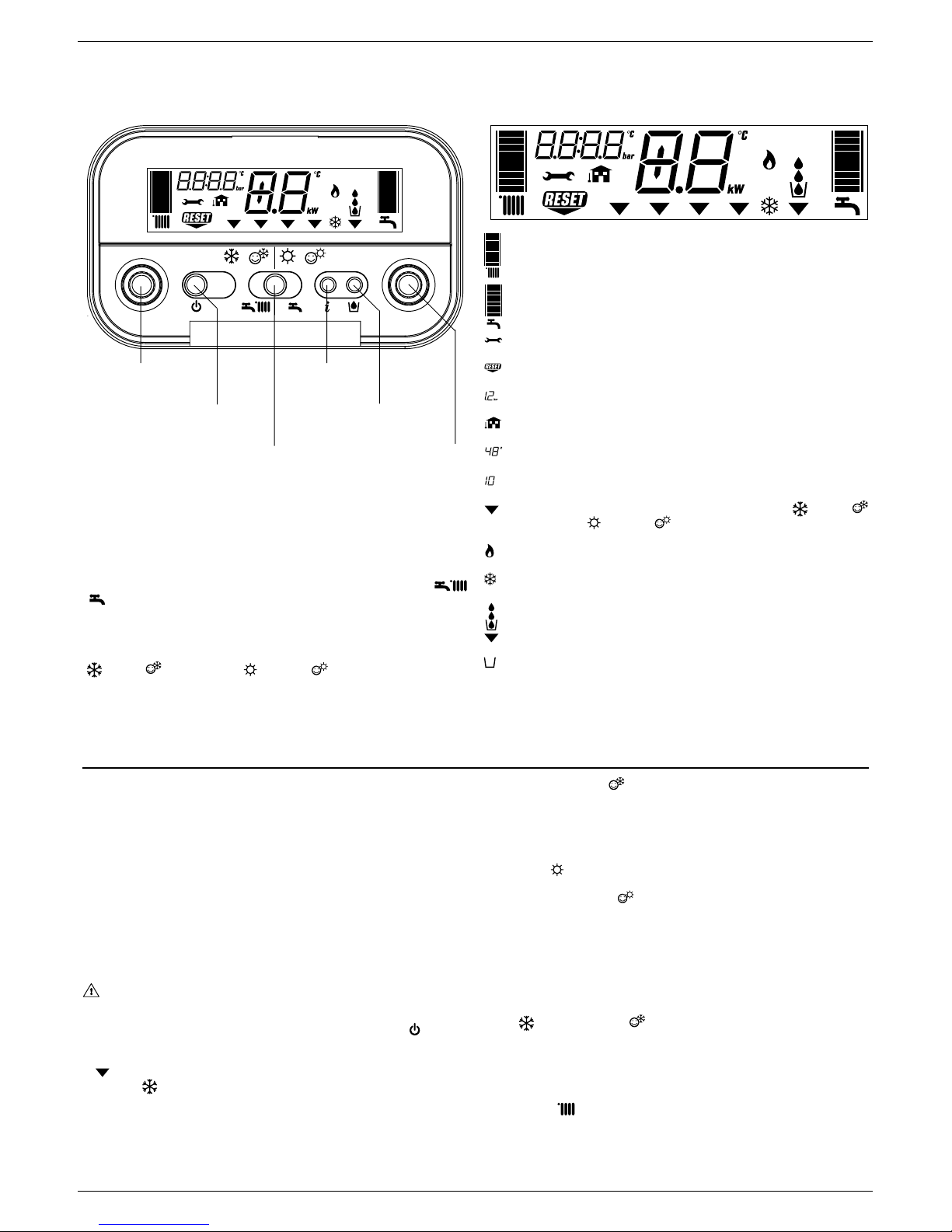
Heating water temperature selector: sets the heating water temperature.
Domestic hot water temperature selector: sets the domestic hot water tem-
perature.
Function key:
ON - the boiler is electrically powered and waiting for operating requests (
- )
OFF - the boiler is electrically powered but will not respond to operating requests
RESET - resets the boiler following a fault
Operating mode button: allows the most suitable operating mode to be selected
(
winter - winter comfort- summer - summer comfort).
Info button: shows a sequence of information concerning the operating status
of the machine.
Filling button: pushing it, the boiler automatically fills the system until the
pressure reaches 1 to 1.5 bar.
graduated heating water temperature scale with heating function symbol
graduated domestic hot water temperature scale with domestic hot water
function symbol
fault symbol (for details, please see page 15)
reset symbol (for details, please see page 15)
pressure value
external sensor connection
heating/domestic hot water temperature
or
fault symbol (e.g. 10 - no flame)
function selector (turned to the chosen operating mode: winter winter comfort- summer - summer comfort)
burner operating symbol
anti-freeze function active symbol
system filling function symbol
fill symbol
12 - START-UP AND OPERATION (GREEN C.S.I.)
The boiler produces heating and domestic hot water. The control panel contains the main boiler control and management functions.
Description of commands Description of display symbols
Switching on
Switch on the boiler as follows:
- access the gas tap through the slots in the cover located in the lower part of
the boiler
- open the gas tap by turning it anti-clockwise (
Fig. 1)
- power the boiler.
When powered, the boiler performs a test sequence and a series of numbers
and letters are shown on the display.
If the test is successful the boiler is ready to work about 4 seconds after the
cycle ends.
The display will look like
Fig. 2.
If the test is unsuccessful, the boiler will not work and a “0” will flash on the
display.
In this case, contact the Technical Assistance Centre.
The boiler turns on in the status it was in before it was switched off: if the
boiler was in the winter comfort mode when it was switched off, it will turn
on again in the winter comfort mode. If it was in the OFF mode, the display
will show two segments in the central area (
Fig. 3). Press the
button to
enable operation.
- press the function selector until the indicator moves to the required function
, depending on the kind of operation chosen.
- WINTER
: with the selector in this position, the heating water and domestic
hot water functions are activated.
In this position the S.A.R.A. function is enabled in the heating mode (see
chapter “Boiler functions”). The boiler actives the temperature stabiliser in
order to ensure the continuous production of domestic hot water, even for
small demands or when the inlet water is already hot. This prevents temperature oscillations due to the burner switching off/on.
- WINTER COMFORT
: with the selector in this position, as well as the
traditional function of heating water and domestic hot water, the preheating
function is also activated which keeps the water in the domestic hot water
exchanger hot in order to reduce waiting times. The S.A.R.A. Booster and
Domestic hot water preheating functions are enabled in this position (see
chapter “Boiler functions”).
- SUMMER
: with the selector in this position, just the traditional domestic
hot water function is activated.
- SUMMER COMFORT
: with the selector in this position, the boiler
provides just domestic hot water with a temperature stabiliser for small
deliveries. Ideal at the times of year or in the areas where the mains water is
already warm. In these conditions, the temperature of the hot water produced
by a boiler with just traditional functions (see SUMMER and WINTER COMFORT) may be instable.
Adjusting heating water temperature
Turning the selector A (
Fig. 4), after having positioned the selector mode on
winter or winter comfort , it is possible to regulate the heating water
temperature.
Turn clockwise to increase the temperature and anticlockwise to decrease.
The bar segments light up (every 5°C) as the temperature is increased. The
selected temperature value appears on the display. If you enter the S.A.R.A.
adjustment field (from 55 to 65°C) while selecting the heating water temperatu-
re, the symbol
and the graduated scale start flashing. For details about the
S.A.R.A. function, read page 12. The selected temperature value appears on
the display.
Domestic hot water
temperature selector
Operating mode button
ON-OFF-RESET
function selector
Filling button
Heating water circuit
temperature selector
INFO button

10
EXCLUSIVE GREEN C.S.I. - R.S.I.
Open position
1
2
3
4
A
+4/5˚C
+3˚C
+2˚C
+1˚C
0˚C
-1˚C
-2˚C
-3˚C
-4/5˚C
5
6
7
B
8
9
10
Tap closed
11
12
13
11
ENGLISH
14
15
17
16
18
19
20
21
22
Adjusting heating water temperature with an external sensor
connected
When an external probe is connected, the value of the delivery temperature is
automatically chosen by the system which rapidly adjusts ambient temperature
to the changes in external temperature. Just the central segment of the bar is
illuminated (
Fig. 5).
To increase or decrease the temperature with respect to the value automatically
calculated by the electronic board, turn the heating water selector clockwise to
increase and anticlockwise to decrease. The bar segments light up (at every
comfort level), correction tolerance lies between - 5 and + 5 comfort levels (
Fig.
5). When choosing the level of comfort, the digit area of the display shows the
required level of comfort while the bar shows the matching segment (Fig. 6).
Adjusting domestic hot water temperature
To adjust domestic hot water temperature, turn switch B (
Fig. 7) clockwise to
increase and anticlockwise to decrease. The bar segments light up (every 3°C)
as the temperature is increased.
The selected temperature value appears on the display.
When choosing the temperature, both for heating and domestic hot water, the
display shows the value being selected. About 4 seconds after the selection
has been made, the modification is memorised and the display returns to the
delivery temperature read by the probe.
Working the boiler
Adjust the ambient thermostat to the required temperature (approx. 20°C). If
there is a demand for heating water, the boiler starts and the
symbol is shown
on the display (Fig. 8). The boiler will remain working until the set temperatures
are reached, after which it will go on stand-by. In the event of ignition or operating
faults, the boiler will perform a “safety stop”.
The flame symbol
will go out and the fault code and will be displayed
(Fig. 9). For a description of faults and how to reset them, consult chapter
“Troubleshooting”.
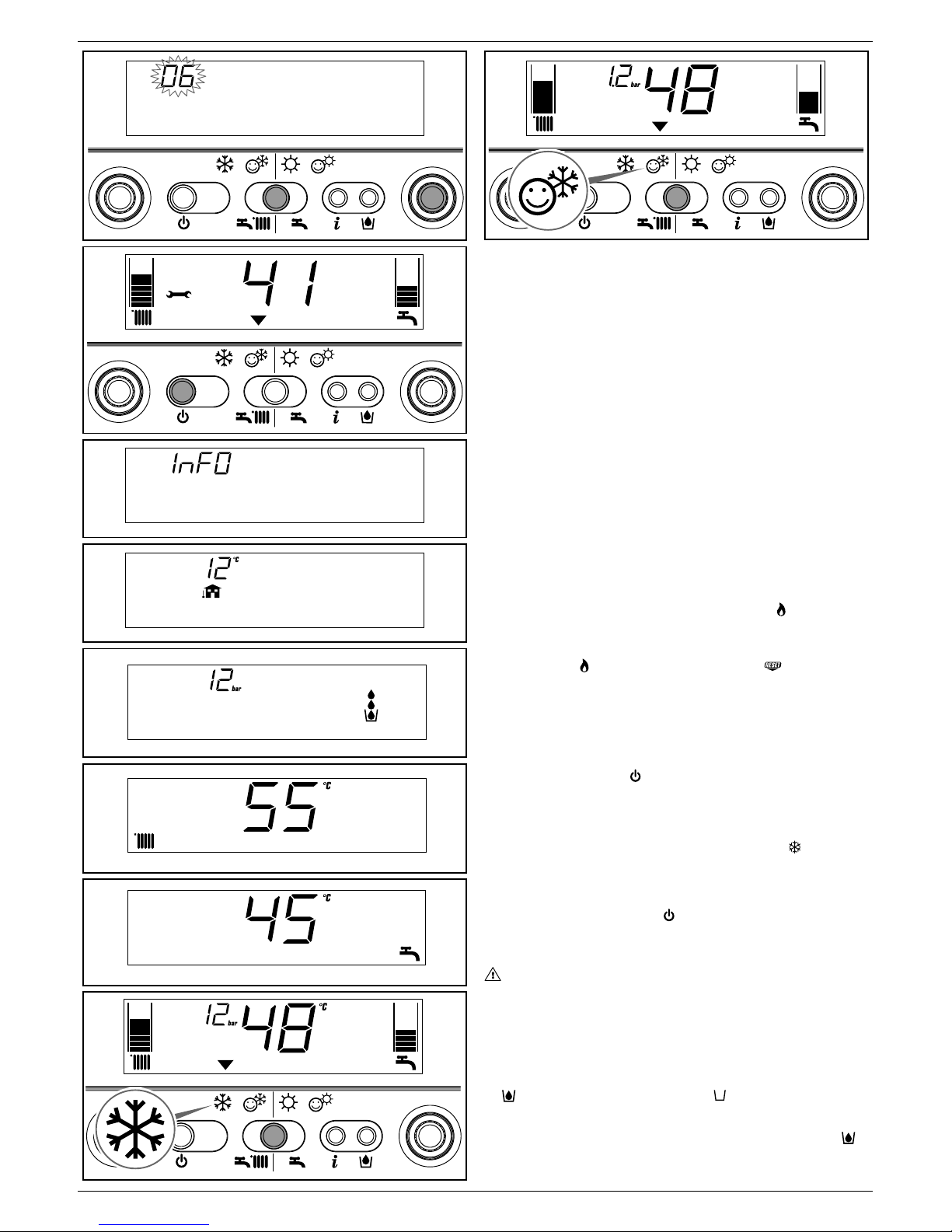
Switching off
Switching off for short periods
For brief absences press the
button to switch off the boiler. The display will
show two segments in the central area (Fig. 3). When the boiler remains powered
with the gas tap open, it is protected by the following systems:
- anti-freeze (
Fig. 10): when the temperature of the water in the boiler falls
below safety values, the circulator and the burner work at minimum power to
increase the water temperature to a safe value (35°C). The
symbol lights
up on the display.
- circulator anti-block: one operating cycle is performed every 24 hours.
Switching off for long periods
For prolonged absences press the
button to switch off the boiler (Fig. 3).
The display will show two segments in the central area. Turn the main switch to
“off”.
Turn off the gas tap under the boiler by turning it clockwise (
Fig. 11).
In this case, the anti-freeze and anti-block systems are disabled. Empty
the water circuit or suitably protect it with a good make of anti-freeze.
Drain the domestic hot water circuit.
Boiler functions
Semi-automatic filling
The boiler features a semi-automatic filling device which turns on by pressing
the
button when the corresponding symbol is shown on the display (Fig.
12).
If this condition occurs it means that the system is incorrectly pressurised though
the boiler will continue to work regularly. Press the circuit filling button
to
start-up the filling sequence.
12
EXCLUSIVE GREEN C.S.I. - R.S.I.
Press the circuit filling button a second time to interrupt the filling sequence.
During filling, the drops of the circuit filling symbol
and the growing pressure
value appear on the display in a cascade sequence (Fig. 13).
After filling, the
symbol is displayed for a few moments and then turns off.
Note
During filling, the boiler does not perform other functions. For example, if there
is a request for domestic hot water, the boiler is unable to provide it until filling
has finished.
Note
If circuit pressure reaches 0.6 bar, the pressure value flashes on the display
(
Fig. 14); if it falls below a minimum safety value (0.3 bar), fault code 41 appears
on the display (Fig. 15) for a certain time, following which, if the fault persists,
fault code 40 is displayed (see chapter on “Troubleshooting”).
In the event of fault 40, press
to reset and then to start filling the circuit.
If you have to fill the system several times, contact the Technical Service Centre
to check whether the heating circuit is watertight (see if there are any leaks).
Information
Press
, the display turns off and just the word InFO appears (Fig. 16). Press
the button
to view operating information. Press the button again to move on to
the next piece of information. If the
button is not pressed, the system
automatically exits the function.
Info list:
Info 0 - shows the word InFO (Fig. 16)
Info 1 - only with the external probe connected, displays external temperature
(e.g. 12°C) (Fig. 17).
The values shown on the display range between - 30°C and 35°C.
Beyond these values the display shows “- -”.
Info 2 - shows circuit pressure (
Fig. 18)
Info 3 - shows the set heating temperature (Fig. 19)
Info 4 - shows the set domestic hot water temperature (
Fig. 20)
Info 5 - displays the set heating temperature, in reference to the second circuit,
only if it is connected.
S.A.R.A. function (
Fig. 21)
If the “winter” mode is selected, the S.A.R.A. (Automatic Ambient Adjustment
System) function can be activated.
Turn the heating water temperature selector to a temperature ranging between
55 and 65°C.
The S.A.R.A. self-adjustment system activates: depending on the temperature
set on the ambient thermostat and the time taken to reach it, the boiler
automatically adjusts the heating water temperature to reduce operating times,
thereby increasing operating comfort and energy saving.
S.A.R.A. BOOSTER function (
Fig. 22)
If the “winter comfort” mode is selected, the S.A.R.A. Booster function is activated
for the heating circuit and reaches the required ambient temperature more
quickly.
DOMESTIC HOT WATER PRE-HEATING function (
Fig. 22)
If the “winter comfort” mode is selected, the domestic hot water Preheating
function is enabled. This function sets out to keep the domestic hot water
contained in the boiler hot, thereby considerably reducing delivery waiting times.
The
function should be selected to reduce power consumption in areas
where the mains water is not particularly cold.
In this case, the Booster and Preheating functions are not activated.
INF2 (
Fig. 23)
It is possible to display information, which may be useful for the Technical
Assistance Centre, by pressing the button
for 10 seconds: the code “INF2”
appears on the display.
Step
1
2
3
4
5
6
7
8
9
10
11-18
Description
Input probe temperature
Return probe temperature
First sanitary probe temperature (*)
Not used in this model
Not used in this model
Second heating system probe temperature
Not used in this model
Ventilator speed /100
Not used in this model
Not used in this model
Historic alarm codes
Display
2 digits
xx
xx
xx
xx
xx
xx
xx
xx
xx
xx
xx
Display
4 digits
01
02
03
Cond
05
06
07
FAN
09
10
HIS0-HIS7
°C
°C
°C
°C
°C
Note (*): if the SAN probe is faulty or disconnected, in the place of the value “- -” is displayed.
INF2 list
23
 Loading...