

Beretta Exclusive GREEN HE C.S.I. 35 kW, Exclusive GREEN HE R.S.I. 35 kW, Exclusive GREEN HE C.S.I. 25 kW, Exclusive GREEN HE R.S.I. 25 kW Installer And User Manual
Page 1
This manual must remain with the user/appliance
EXCLUSIVE
GREEN HE
C.S.I. - R.S.I.
EN NZINSTALLER AND USER MANUAL NZ Edition 2017-1
ES MANUAL DEL INSTALADOR Y DEL USUARIO
PT MANUAL DO USUARIO E DO INSTALADOR
HU TELEPiTOI ES FELHASZNAL6I KEZIKONYV
RO MANUAL DE INSTALARE SI UTILIZARE
SI NAVODILA ZA VGRADITEV, PRIKLJUCITEV IN UPORABO
PL INSTRUKCJA OBSt.UGI I INSTALACJI KOTt.A GAZOWEGO
Page 2

2
EXCLUSIVE GREEN HE C.S.I. - EXCLUSIVE GREEN HE R.S.I.
RANGE RATED
This boiler can be adapted to the heating requirements of the system, it is possible to change the maximum output in central heating. Refer to chapter "Adjustments"
for calibration.
After setting the desired output (parameter 23 maximum heating) Please note the adjusted setting on the boiler.
ES
RANGE RATED
Esta caldera puede adaptarse a los requisitos de calefacción del sistema, es posible cambiar la potencia máxima en la calefacción central. Para la
calibración, consultar el capítulo “Regulaciones”.
Después de ajustar la potencia deseada (parámetro 23 calefacción máxima) apunte el valor en la tabla de la contraportada de este manual para
futuras referencias.
PT
FAIXA CLASSIFICADA
Esta caldeira pode ser adaptada às especificações de aquecimento do sistema, é possível modificar a saída máxima no aquecimento central.
Consulte o capítulo “Ajustes” para a calibração.
Após definir a saída desejada (parâmetro 23 de aquecimento máximo), relate o valor na tabela na contracapa deste manual, para consultas futuras.
HU RANGE RATED
A bojler a rendszer fűtési igényeihez igazítható. A központi fűtés maximális teljesítménye módosítható. A beállításhoz lásd a “Szabályozás” részt.
A megfelelő teljesítmény (23-as paraméter, maximális fűtés) beállítása után jegyezze fel az értéket a kézikönyv hátsó borítóján lévő táblázatba.
RO
GAMA NOMINALA
Această centrală poate fi adaptată la cerinţele de încălzire ale sistemului; este posibil să modificaţi puterea maximă în încălzirea centrală
Pentru calibrare, consultaţi capitolul “Reglaje”.
După ce setaţi puterea dorită (parametrul 23 încălzire maximă) indicaţi valoarea curentă în tabelul de la sfâr itul acestui manual, pentru referinţe ulterioare.
SL
RANGE RATED
Ta kotel se lahko prilagodi zahtevam sistema po toploti, pri centralnem ogrevanju se mu lahko spremeni največjo moč. Za umerjanje glejte poglavje
“Nastavitve”.
Po nastavitvi želene izhodne moči (parameter 23, največje ogrevanje) vnesite vrednost v tabelo na zadnji ovitek tega priročnika, za nadaljnjo uporabo.
PL
ZAKRES REGULACJI MOCY
Kocioł ten można dostosować do wymagań systemu centralnego ogrzewania, ponieważ istnieje możliwość obniżenia maksymalnej mocy na c.o. W tym
celu należy zapoznać się z rozdziałem Regulacje”
W przypadku zmiany wartości mocy maksymalnej (parametr 23) należy umieścić aktualną wartość w tabeli znajdującej się na końcu niniejszej instrukcji.
Jest to bardzo istotne w przypadku wykonywania przeglądów urządzenia.
SI
SI
PL
EN
PL
PT
ES
HU
RO
EN
ES
PT
HU
RO
This boiler manual contains information and specifications for CSI and RSI models
For New Zealand CSI model only applies
CSI = Combination boiler with on demand DHW
RSI = system boiler N/A
Installation of this appliance requires a certifying Gas fitter
Electrical connections should be by a suitably qualified Electrician
Distributed in NZ by Tradepoint LTD (Heat IQ) Wanganui NZ 063447392
EXCLUSIVE GREEN boiler complies with basic requirements of the
following Directives: Gas directive 2009/142/EEC; Yield directive 92/42/
EEC; Electromagnetic compatibility directive 2004/108/EEC; Low-voltage
directive 2006/95/EEC; Regulation 677 for condensation boilers. Thus, it is
EC-marked.
La caldera EXCLUSIVE GREEN cumple con los requisitos básicos de
las siguientes Directivas: Directiva Gas 2009/142/EEC; Directiva
rendimiento 92/42/EEC; Directiva compatibilidad electromagnética
2004/108/EEC; Directiva baja tensión 2006/95/EEC; Regulación 677 para
calderas de condensación. Por lo tanto, tiene el marcado CE.
A caldeira EXCLUSIVE GREEN é compatível com as especificações
básicas das seguintes Directivas: Directiva de gás 2009/142/EEC; Directiva
de rendimento 92/42/EEC; Directiva de compatibilidade electromagnética
2004/108/EEC; Directiva de baixa tensão 2006/95/EEC; Regulação 677
para caldeiras de condensação. Assim, é marcada com EC.
Az EXCLUSIVE GREEN kazán teljesíti az alábbi irányelvek lényegi
követelményeit: 2009/142/EGK sz. gáz irányelv; 92/42/EGK sz. irányelv a
vízmelegítő kazánokról; 2004/108/EGK sz. irányelv az elektromágneses
összeférhetőségről; 2006/95/EGK sz. irányelv a kisfeszültségű
berendezésekről; Kondenzációs kazánokra vonatkozó 677 sz. szabvány. Így
jogosan viseli a CE-jelet.
Centrala EXCLUSIVE GREEN este fabricata in conformitate cu cerintele
urmatoarelor Directive: Directiva gaz 2009/142/EEC; Directiva eficienta
92/42/EEC; Directiva compatibilitate electromagnetica 2004/108/EEC;
Directiva voltaj redus 2006/95/EEC; Regulamentul 677 referitor la centrale
cu condensare. Prin urmare, este marcat cu simbolul CE.
Kotel EXCLUSIVE GREEN ustreza temeljnim zahtevam Naslednjih Uredb:
Uredba o plinu 2009/142/CEE; Uredba o izkoristkih92/42/CEE; Uredba
o elektromagnetni ustreznosti 2004/108/CEE; Uredba o nizki napetosti
2006/95/CEE; Uredba o kondenzacijskih kotlih 677. Torej nosi oznako CE.
KocioU
EXCLUSIVE GREEN
nast�pujqcych dyrektyw : - Urzqdzenia spalajqce paliwa gazowe
2009/142/EEC; Sprawnosc energetyczna
Kompatybilnosc energetyczna 2004/108/EEC; Niskonapi�ciowe wyroby
elektryczne 2006/95/EEC; Norma
w CE
HE
speUnia
podstawowe wymagania
kotU6w
dotyczqca
kotU6w
wodnych
0694
92/42/EEC;
kondensacyjnych 677;
Installer’s-user’s manual ..................................................................................
Boiler operating elements ................................................................................
Hydraulic circuit ...............................................................................................
Electric diagrams .............................................................................................
l
Installer’s-user’s manual .............................................................................. 28
Boiler operating elements .......................................................................... 172
Hydraulic circuit .................................................................................. 173-174
Electric diagrams ................................................................................ 175-176
Installer’s-user’s manual .............................................................................. 52
Boiler operating elements .......................................................................... 172
Hydraulic circuit .................................................................................. 173-174
Electric diagrams ................................................................................ 175-176
Telepítői kézikönyv-felhasználói kézikönyv ................................................. 76
A kazán funkcionális alkatrészei ................................................................ 172
Vízkeringetés ..................................................................................... 173-174
Villamos kapcsolási rajz ..................................................................... 175-176
Manual instalator-utilizaor ...........................................................................100
Elemenetele functionale ale centralei. ....................................................... 172
Circuit hidraulic .................................................................................... 173-174
Scheme electrice ................................................................................ 175-176
Navodila za vgraditelja-uporabo ................................................................ 124
Sestavni deli kotla ...................................................................................... 172
Hidravlična napeljava ......................................................................... 173-174
Električna shema ..................................................................................... 175-176
lnstrukcja instalacji i uzytkowania .................................................................. 148
Budowa kotU
Obieg hydrauliczny ................................................................................. 173-174
Schematy elektryczne ............................................................................ 175-176
a ............................................................................................
172
Page 3

3
ENGLISH
Model
Type
Category
Power
C.S.I.
combined C
25-35 K7
R.S.I.
CH only C
25-35 K7
ENGLISH NZ edition
1
- GENERAL SAFETY DEVICES
The boilers produced in our factory are built with care down to the last
component to protect both the user and installer from eventual accidents.
We recommend personel working on the appliance
should pay particular attention to the wiring, especially the
connections, that must not be exposed outside the terminal board
to prevent any contact with the live parts of the wiring.
This instruction manual is an integral part of the product. Make sure it
remains with the boiler, even if it is transferred to another owner
or user.
This boiler may only be installed and serviced by qualified fitters who
Have the appropriate NZ Gas and Electrical qualifications
Install must comply with NZ code
The boiler must be serviced at least once a year.
The installer must instruct the user in the operation of the boiler
and its safety devices.
This boiler may only be used for what it was expressly built to do. The
manufacturer declines all contractual and non-contractual liability for
injury to persons or animals or damage to property deriving from errors
made during installation, adjustment and servicing and from improper
use.
If this appliance is used to produce hot water it must be connected
to a heating and/or a domestic hot water system, according to its
performance and power.
After removing the packaging, make sure the contents are undamaged
and complete. If this is not the case, contact your dealer.
The safety valve outlet must be connected to a suitable drain. The
manufacturer declines all liability for any damage caused by the an
incorrect safety valve discharge.
The safety and automatic adjustment devices on the appliance must
never be modified during its lifetime,.
If the appliance develops a fault and/or works badly, switch it off and do
not attempt to repair it yourself.
, inform the user that:
-
in the event of leaks, he/she Must shut off the water supply and
promptly seek professional support.
-
Must check from time to time to make sure
on the control panel. This symbol means that the pressure in the
water system is incorrect. If necessary, fill the system as described
in the paragraph “Boiler functions”
-
GREEN HE R.S.I.: must periodically check, on the display, that the
pressure value is between 1 and 1,5 bar; if not fill the system as
described in the paragraph “Boiler functions”
-
if the boiler is not planned to be used for a long period, he/she
should call in the Technical Assistance Service to perform the following
operations:
-
turn off the main boiler and general system switches
-
close the gas and water taps on both the heating (GREEN HE
C.S.I.-GREEN HE R.S.I.) and domestic hot water circuits (GREEN
HE C.S.I. only)
-
drain the heating (GREEN HE C.S.I.-GREEN R.S.I.) and domestic
hot water (GREEN HE C.S.I. only) circuits to prevent freezing.
the
Connect the outlet collector to a suitable outlet system (refer to chapter 5).
Safety measures:
The boiler should not be used by children or unassisted disabled people
electrical devices or equipment, such as switches, appliances, etc.,
should not be used if there is a smell of gas or fumes. If there is a gas
leak, open all the doors and windows to ventilate the area, turn off the
general gas tap and immediately call the Technical Assistance Service
do not touch the boiler if your hands are wet or damp
Press the button until “- -” is shown on the display and disconnect the
electricity supply by turning off the two-position system switch, before
cleaning
Do not modify the safety or adjustment devices without the
manufacturer’s permission and relative instructions
Do not pull, detach or twist the wires from the boiler even if they are not
connected to the power supply
symbol is not lit
Do not block or reduce the size of the ventilation openings in the room
Do not leave inflammable containers or substances in the room
keep packaging out of reach of children
only use appliance for purposes it is devoted to
Do not lean any object on the boiler
Do not tamper with sealed elements
Do not block the condensate outlet.
2
- BOILER INSTALLATION
Boiler must only be installed by qualified personnel.
Boiler is available in the following models:
Exclusive GREEN HE C.S.I.
is a C-type condensation wall-mounted boiler for heating and producing
on demand domestic hot water;
Exclusive GREEN HE R.S.I.
Some reference is made to this model within the manual.
Exclusive Green HE boilers are fitted with:
-
Smart pumps with auto speed adjusting
-
1- 10 modulation, the boiler is designed to automatically modulate the flow
rate supplied between a maximum and a minimum (see technical data)
-
Range Rated, indicates that the boiler has a device for adapting to the
system’s heat requirements, making it possible to adjust the boiler’s flow
rate to the energy requirements of the building
The following types of fumes outlet are available for this kind of boiler:
B23P; B53P; C13,C13x; C23; C33,C33x; C43,C43x; C53,C53x; C63,C63x;
C83,C83x, C93,C93x.
In B23P configuration (if installed inside), do not install the apparatus in
rooms used as bedrooms, bathrooms, showers or where there are open
vent stacks without own air exchange. The boiler must be installed in an
adequately ventilated room. See the UNI-CIG 7129-7131 and UNI 11071
standards for detailed instructions on installing vent stacks, gas pipes and
to ventilate the room.
In C configuration the boiler can be installed in any type of room and there
are no limits to aeration conditions and size of room.
FOR CORRECT INSTALLATION, WE REMIND YOU THAT:
-
The boiler must not be installed over a stove or any other cooking equi-
pment or within a bathroom.
-
minimum spaces are to be left in order to allow maintenance operations:
at least 5,0 cm every side and 20 cm under the boiler
-
it is forbidden to leave inflammable substances in the room
-
suitably fire line any heat-sensitive walls (e.g.: wood lined).
A support plate and integrated pre-installation template are provided for
with
the boiler (FIG. 1.1).
(PWM = Pulse-width modulation))
Mounting instructions:
-
fix the boiler support plate (F) with the template (G) to the wall and use a
plumb to check that it is perfectly horizontal
-
trace out 4 holes (Ø 6 mm) for fixing the boiler support plate (F) and 2
holes (Ø 4 mm) for fixing the pre-installation template (G)
-
make sure all the measurements are correct, then drill holes in the wall
using a drill and point with the diameter given previously
-
fix the plate to the wall by the supplied anchor screws
-
make hydraulic connections.
After installing the boiler, the screws
after
installing the boiler and connecting it to the water and gas supplies, fit
the
lower cover (
the lower case with the screw C (FIG. 1.4) -
in the boiler.
A-B
, FIG. 1.3) so that its hooks slip into the lower paart of the boiler and fix
D1
(FIG. 1.2) can be removed.
Contained in the documentation envelope
Page 4

4
EXCLUSIVE GREEN HE C.S.I. - R.S.I.
Parameters
um
Water in
heating
circuit
Inlet
water
PH
7÷8
Hardness —& -
15÷20
Appearance
- limpid
Residual head (m.c.a.)
EXTERNAL SENSOR YES
((HEAT REGULATION))
EXTERNAL SENSOR NO
(NO HEAT REGULATION)
HIGH
TEMPERATURE
(
radiators
without
thermostatic
valves)
02/0/24)/.!,
(09o = 41)
T constant
(2≤P90≤40)
LOW
TEMPERATURE
(floor
)
02/0/24)/.!,
(09o = 41)
02/0/24)/.!,
(09o = 41)
HIGH
TEMPERATURE
(radiators
with
thermostatic
valves)
02/0/24)/.!,
(09o = 41)
02/0/24)/.!,
(09o = 41)
Cleaning the system and characteristics of heating circuit water
After installing a new system or replacing a boiler, Flush the system.
To ensure the product works correctly, after cleaning, and/or chemically
treating the system (e.g.: Inhibitors, antifreeze, etc.), make sure the
characteristics of the water satisfy the parameters indicated in the table.
If water hardness exceeds 28 Fr,
we recommend the use of a water softener,
to prevent any limescale deposit in boiler due to excessively hard water.
PUMP DUTY
Exclusive Green HE boilers are fitted with a variable speed circulation unit
that is already connected up in terms of plumbing and electrics, and the
usable performance it provides is shown in the graph.
The boilers are fitted with an anti-blocking system that starts an operating
cycle every 24 hours when not used, irrespective of the position of the function selector.
The “anti-blocking” function is only active when the electrical power
supply to the boiler is on.
Operating the appliance pump without water is forbiden
VARIABLE SPEED CIRCULATION UNIT
The modulating circulating function is only active for the heating function.
When the three way valve switches to DHW the pump works at max speed
unit is set at maximum speed. The modulating circulation function applies
only to the boiler circulation unit and not to circulation units on any external
devices connected to it (e.g. booster circulation unit).
Any of 4 operating modes can be chosen, depending on situations and the
type of plant.
By accessing parameter 90 in the technical menu, one of the following possibilities can be chosen:
1
- VARIABLE SPEED CIRCULATION UNITWITH PROPORTIONAL MODE
(41 <= P90 <= 90)
2
- VARIABLE SPEED CIRCULATION UNIT WITH CONSTANT DT MODE
(2 <= P90 <= 40)
3
- VARIABLE SPEED CIRCULATION UNIT WITH MAXIMUM FIXED
MAXIMUM SPEED MODE (P90 = 1)
4
– EXCEPTIONAL USE OF A STANDARD CIRCULATION UNITWITHOUT
SPEED ADJUSTMENT (P90 = 0)
1
- VARIABLE SPEED CIRCULATION UNITWITH PROPORTIONAL MODE
(41 <= P90 <= 90)
In this mode the boiler’s board determines what flow rate curve to adopt
according to the instantaneous power supplied by the boiler.
The boiler controller breaks down the power range within which the boiler
operates in heating mode into various levels. Depending on the power level
in use when heating, one of the speeds available is selected automatically
according to logic: Max power = HIGH SPEED, Min power = LOW SPEED.
This is used on all types of plants where the machine’s power has been
correctly balanced with the plant’s real needs.
Operationally:
- Access parameter 90
- Set the parameter = 41
Note
: The Parameter 90 = 41 setting is recommended by the manufacturer.
Values exceeding 41 are used in specific cases.
2
- VARIABLE SPEED CIRCULATION UNIT WITH CONSTANT DT MODE
(2 <= P90 <= 40)
In this mode the installer sets the T value to be maintained between the
delivery and return (e.g. if a value of 10 is entered, the circulation unit’s
speed will change to implement a plant flow rate aimed at maintaining the
between the inlet and outlet of the heat exchanger AT 10 Deg C
By periodically sampling values provided by the boiler delivery/return
sensors, the board increases or decreases the circulation unit’s speed and
therefore the plant’s flow rate. If the sampling shows a T value lower than
that set, the speed is reduced until the T increases to the value set. Viceversa if sampling is higher than the value set, the speed is increased.
This is used for direct high temperature plants (typical of replacement),
where the boiler is not thermostatically controlled, and where a calculated
delta T can be set.
When working with a constant delivery temperature and attainment of
stabilising the ambient conditions, the average temperature of the radiators
tends to increase. By keeping T constant, the reduction in the flow rate is
obtained by changing the operating curve, which produces a lower return
temperature that in turn favours high boiler performance and the reduction
of electricity consumption.
Operationally:
-
Access parameter 90
-
Set the parameter at a value between 2 and 40 (normally between 10
and 20).
3
- VARIABLE SPEED CIRCULATION UNIT WITH MAXIMUM FIXED
MAXIMUM SPEED MODE (P90 = 1)
In this mode the modulating circulation unit works constantly at maximum
speed.
It is used on plants with a high load loss in which the boiler’s head must be
used as much as possible in order to guarantee sufficient circulation (plant
flow rate at maximum speed lower than 600 litres per hour).
This is used when bottles of mixture are involved, with high flow rates in
the circuit downstream.
Operationally:
- Access parameter 90
- Set the parameter = 1
4
– EXCEPTIONAL USE OF A STANDARD CIRCULATION UNIT WITH-
OUT SPEED ADJUSTMENT (P90 = 0)
This mode must be used in exceptional cases in which the boiler is to
be used with a traditional circulation unit without a speed adjustment. It
presupposes that the adjustable speed circulation unit has been removed
and replaced with a non-adjustable speed circulation unit.
Warning !!!! The BE06 board connected to connector CN9 must be
removed and replaced with a connector with a jumper to be inserted into
connector CN9. This latter connection is obligatory and if not formed
may cause the system to malfunction.
Operationally:
- Access parameter 90
- Set the Parrameter = o
CONFIGURATIONS RECOMMENDED BY THE MANUFACTURER
6,0
5,8
5,6
5,4
5,2
5,0
4,8
4,6
4,4
4,2
4,0
3,8
3,6
3,4
3,2
3,0
2,8
2,6
2,4
2,2
2,0
1,8
1,6
1,4
1,2
1,0
0,8
0,6
0,4
0,2
0,0
0 100 200 300 400 500 600 700 800 900 1000 1100 1200
Plant flow rate (l/h)
Page 5

5
ENGLISH
3
- HYDRAULIC CONNECTIONS
Position and dimensions of hydraulic connections are specified in figure 1.1:
A - CH return 3/4”
B - CH delivery 3/4”
C - Gas connection 3/4”
D -
DHW
outlet
E –
DHW
F - Support plate
G - Pre-installation template
4
- IF INSTALLING AN EXTERNAL Thermoregulation Sensor
The sensor (FIG. 1.6) MUST BE INSTALLED ON AN EXTERNAL WALL of the building
while taking care to comply with the instructions below:
-
It must be fitted on the facade most often exposed to wind, on a wall facing
South or South west (southern Hemisphere).
-
It must be fitted about 2/3 up the height of the façade.
-
It must not be near any doors, windows, outlets for air ducts, or near
chimneys or other heat sources.
The electrical connection to the external sensor must be formed using a twopole cable (not supplied), with a cross-section of 0,5 to 1 mm2 and a maximum
length of 30 metres. It is not necessary to worry about the polarity of the cable
for the connection to the external sensor. Do not form joints in this cable.
If a joint has to be made it must be watertight and adequately protected.
Any conduit used for the connection cable must be separate from the
conduits used for the power cables (230 Vac).
WALL MOUNTING OF THE EXTERNAL SENSOR.
Install the probe in an area of smooth wall; for brick walls or other irregular
surfaces, prepare a smooth contact area if at all possible.
Remove the upper plastic cover by turning it anti-clockwise.
Identify the wall fixing point and drill a hole for the 5x25 expansion grip.
Insert the expansion grip into the hole.
Remove the card from its housing.
& fix to the wkll using the screw supplied
Attach the bracket and tighten the screw.
Loosen the cable grommet screw, push in the probe connection cable and
connect it to the electrical terminal.
inlet
(CSI) ½”
(CSI) ½”
Remember to firmly secure the cable grommet to prevent humidity from
entering.
Put the card back into its housing. Close the upper plastic cover by turning
clockwise , firmly secure the cable grommet
5
- CONDENSATE COLLECTION TRAP
The outlet c
water from the safety valve and the system drain outlet water.
ollector A (FIG. 1.
7)
collects the condensate water any evacuation water , the
The collector must be connected, by means of a discharge pipe (not
sup- plied), to a suitable drain.
The external diameter of the collector hose is 20 mm: we therefore
suggest using an Ø 18-19 mm pipe, to be closed with a suitable
clamp (not supplied).
The manufacturer is not responsible for any damage caused by the lack
of a collection system.
The outlet connection line must have a guaranteed seal.
The manufacturer of the boiler is not responsible for any flooding caused
by interventions of the safety valve.
6
- GAS CONNECTION
Before connecting appliance to gas pipe network, check the following:
-
regulations in force are met
-
gas type used is the same as set for appliance operation
-
pipes are clean.
Gas must be piped externally. If the pipe goes through a wall it must go through
the central opening in the lower part of the template. It is recommended to
install an appropriately sized filter on the gas line in case gas from the mains
contains some small solid particles. After installation make sure that all the
joints have been made airtight conforming to standard installation practices.
7
- ELECTRIC CONNECTION
To access the electrical connections, proceed as follows:
-
unscrew the lower cover fixing screw C, (FIG. 1.4)
-
pull the cover towards you and remove (A-B) (FIG. 1.5)
-
loosen the fixing screws (D) and remove the shell (FIG. 1.2)
-
lift up the panel and turn it forwards
-
open the terminal board covers making them slide in the direction of the
arrows (FIG. 1.8: E high voltage connections 230 V, F low voltage connec-
tions, G water tank sensor connections only ( R.S.I.).
Connect the appliance to the mains power supply with a switch featuring a
distance of at least 3,5 mm (EN 60335-1, category III) between each wire.
The appliance uses alternating current at 230 Volt/50 Hz, has a power input
OF 88 w (25KW CSI.- 25KW RSI).) & 116 w (35KW RSI. - 35KW CSI)
and complies with EN 60335-1 standard. Connect the boiler to a safe earth
circuit according to current legislation.
Live and neutral (L-N) connections should also be respected.
The boiler can operate with phase-neutral or phase –phase power supply. For
floating power supply, without an earth-bonded conductor, it is necessary to
use an insulation transformer with secondary anchored to ground.
The earth conductor must be a couple of cm longer than the others.
Gas and/or water pipes may not be used to earth electrical equipment.
The installer is responsible for making sure that the appliance has an
adequate earth system; the manufacturer shall not be held liable for
eventual damages caused by incorrect usage or failing to earth the
boiler.
Use the supplied power cable to connect the boiler to the mains power
supply.
Connect the ambient thermostat and/or time clock as shown in the electrical
diagrams.
When replacing the power cable, use a HAR H05V2V2-F cable, 3 x 0,75
mm2, Ø max. external 7 mm.
8
- FILLING AND EMPTYING THE SYSTEM
The central heating system can be filled up once the water mains have been
connected.
This must be done while the installation is cold by:
-
Turn the caps of the lower (A) and upper (E) automatic bleed valves two
or three turns; leave A and E valve caps open for continual air venting
(FIG. 1.9);
-
Making sure the cold water inlet tap is open
-
Opening the filling tap (B, on the boiler for until the pressure on the
gauge (C) is between 1 and
Close the filling tap after filling.
The boiler is equipped with an efficient air separator so that there is no need
to do anything manually.
The burner only ignites when air venting has finished.
NOTE: air extraction from the boiler takes place automatically, through two
automatic bleeding valves, A and E.
The first is situated on the pump, while the second is inside the air chamber.
NOTE the boiler is also equipped with a semi-automatic filling system. The
first system-filling operation must be carried out by opening tap B with the
boiler turned off.
1,5 Bar (BLUE ZONE) (FIG. 1.9).
Emptying
Before starting to empty the boiler, isolate power switch for the system (off)
Close the isolation devices for the thermal system
-
Loosen the system outlet valve (D) manually
-
The water from the system is discharged through the outlet collector (F).
DHW system emptying (C.S.I. Combi only)
:
-
turn off the tap at the mains cold inlet
-
turn on all the hot and cold taps
-
empty out the lowest parts of the system.
Page 6

6
EXCLUSIVE GREEN HE C.S.I. - R.S.I.
Max linear length concentric
duct Ø 60-100 mm
Pressure drop for each
bend (45°/90°) [m]
25 C.S.I.-R.S.I.
8,85 m
1,3 / 1,6
35 C.S.I.-R.S.I.
8,85 m
Max length fumes
outlet duct Ø 80 mm
Pressure drop for each
bend (45°/90°) [m]
25 C.S.I.-R.S.I.
50 m
1 / 1,5
35 C.S.I.-R.S.I.
60 m
Max linear length concentric
duct Ø 60-100 mm
Pressure drop for each
bend (45°/90°) [m]
25 C.S.I.-R.S.I.
7,85 m
1,3 / 1,6
35 C.S.I.-R.S.I.
7,85 m
To Purge air from the heating system & boiler (Fig. 1.10)
We recommend carrying out the sequence of
operations below during installation and after
exceptional maintenance
1. Using a spanner open the manual air vent valve located above the air
box; the tube supplied with the boiler must be connected to the valve
to let out the water into a container.
2. Open the manual system filling valve
3.
Switch on the boiler leaving the gas valve closed;
4.
Use the room thermostat or the remote control panel to activate request
INSTALLATION “SEALED” (TYPE C)
This boiler is a C-type appliance (sealed chamber) and must be safely
connected to fume exhaustion duct and burning air suction duct, both
terminating outside; This appliance cannot operate without these ducts.
Concentric outlets (Ø 60-100) (Fig. 1.14)
Concentric ducts may be placed in the most suitable direction for installation
requirements but special care must be taken as regards the and the length
of the Flue.
Horizontal
for heat so that the three-way will turn to heating
5.
Activate request for hot water as follows:
turn on a tap for 30 seconds every minute so that the three-way cycles
from heating to domestic hot water and vice versa about ten times
(here the boiler will go into alarm as it lacks gas and will have to be reset
each time this happens
6.
Continue the sequence until water only comes out of the manual air vent
valve; close the manual air vent valve at this point;
7.
Make sure the system is at the correct pressure (1- 1.2 bar is ideal);
8.
Close the manual system filling valve;
9. Open the gas valve and ignite the boiler
9
- FUMES EXHAUSTION AND BURNING AIR SUCTION
EXHAUSTION CONFIGURATIONS (Fig. 1.11-1.12)
Boiler is homologated for the following exhaustion configurations:
B23P-B53P - Suction in room and discharge outside
C13 - Concentric wall exhaustion. Pipes can separately start from boiler,
but outlets must be concentric or close enough to be subject to similar wind
conditions (within 50 cm)
C23 - Concentric exhaustion in common chimney (suction and exhaustion
in the same chimney)
C33 -
#ONCENTRIC ROOF EXHAUSTION. /UTLETS LIKE #13
C43 - Exhaustion and suction in common separate chimneys, but subject
to similar wind conditions
C53
- 7ALL OR ROOF S
EPARATE EXHAUSTION AND SUCTION IN DIFFERENT PRESSURE AREAS.
Exhaustion and suction must never be located on opposite walls
C63 - Exhaustion and suction with separately certified and sold pipes (1856/1)
C83 - Single or common chimney exhaustion and wall suction
C93 – Exhaust on roof (similar to C33) and air
Vertical
linear length means without bends,
Allow 0.5 m per bend in total length calculation.
The Flue outlet pipe MUST SLOPE BY 1% TOWARDS the condensate collector (boiler)-
CAUTION
Exhaust fume outlets are potential hazards.
The boiler automatically adapts ventilation according to the type of
installation and the length of the duct.
Do not obstruct or narrow the combustion air inlet duct in any way.
To install follow the instructions supplied with the kit.
.
Refer to regulations in force for exhaustion of combustion products.
Boiler is provided for without fume exhaustion/air suction kit, since forced
draught sealed chamber accessories can be used, as they better adapt to
installation characteristics.
&OR FUME EXTRACTION AND BURNING AIR RESTORATION IN BOILER, USE ORIGINAL PIPES OR
other EC-certified pipes with equivalent characteristics; check connection is
correct as shown on instructions fume accessories provided for with. More
appliances can be connected to a single chimney, provided that all appliances
are condensing type.
“FORCED OPEN” INSTALLATION (TYPE B23P-B53P, intake inside
and outlet outside) - Fumes outlet duct Ø 80 mm (Fig. 1.13)
The fumes outlet duct can be aimed in the most suitable direction for instal-
lation needs. To install follow the instructions supplied with the kit.
In this configuration, the boiler is connected to the Ø 80 mm fumes outlet
duct by means of a Ø 60-80 mm adaptor.
In this case, the combustion supporting air is taken from the room in
which the boiler is installed, which must be a suitable and ventilated
technical room.
Non-insulated fumes outlet ducts are potential sources of danger.
0ROVISION MUST BE MADE FOR A 1% SLOPE OF THE FUMES OUTLET DUCT TOWARDS
the boiler.
Page 7

7
ENGLISH
10 - TECHNICAL DATA
C.S.I. 25 kW
C.S.I. 35 kW
R.S.I. 25 kW
R.S.I. 35 kW
CH Nominal thermal flow rate
K7
25,00
34,60
25,00
34,60
kcal/h
21.500
29.756
21.500
29.756
.OMINAL THERMAL POWER (8o—/6o—)
K7
24,38
33,74
24,38
33,74
kcal/h
20.963
29.012
20.963
29.012
.OMINAL THERMAL POWER (5o—/3o—)
K7
26,20
36,50
26,20
36,50
kcal/h
22.532
31.393
22.532
31.393
Reduced thermal flow rate (G20/G31)
K7
2,50/4,50
3,50/6,20
2,50/4,50
3,50/6,20
kcal/h
2.150/3.870
3.010/5.332
2.150/3.870
3.010/5.332
2EDUCED THERMAL POWER (8o—/6o—) ('2o/'31)
K7
2,49/4,47
3,41/6,04
2,49/4,47
3,41/6,04
kcal/h
2.144/3.847
2.929/5.193
2.144/3.847
2.929/5.193
2EDUCED THERMAL POWER (5o—/3o—)('2o/'31)
K7
2,69/4,82
3,71/6,57
2,69/4,82
3,71/6,57
kcal/h
2.309/4.145
3.188/5.647
2.309/4.145
3.188/5.647
Nominal thermal flow rate Range Rated heat (Cn)
K7
25,00
34,60
25,00
34,60
kcal/h
21.500
29.756
21.500
29.756
Minimal thermal flow rate Range Rated (Qm) (G20/G31)
K7
2,50/4,50
3,50/6,20
2,50/4,50
3,50/6,20
kcal/h
2.150/3.870
3.010/5.332
2.150/3.870
3.010/5.332
DHW*
Nominal thermal flow rate
K7
25,00
34,60
-
-
kcal/h
21.500
29.756
-
-
Maximum thermal power**
K7
25,00
34,60
-
-
kcal/h
21.500
29.756
-
-
Reduced thermal flow rate** (G20/G31)
K7
2,50/4,50
3,50/6,20
-
-
kcal/h
2.150/3.870
3.010/5.332
-
-
Minimum thermal power** (G20/G31)
K7
2,50/4,50
3,50/6,20
-
-
kcal/h
2.150/3.870
3.010/5.332
-
-
7ORKING EFlCIENCY 0N MAX
- 0N
MIN (8o-6o—)
%
97,5-99,7 ('31= 99,4)
97,5-97,3 ('31=97,4)
97,5-99,7 ('31= 99,4)
97,5-97,3 ('31=97,4)
7ORKING EFlCIENCY 3o% (47— RETURN)
%
102,8
103,1
102,8
103,1
Combustion efficiency
%
97,8
97,7
97,8
97,7 7OR
KING EFlCIENCY 0N MAX
- 0N
MIN (5o-3o—)
%
1o4,8-1o7,4 ('31= 1o7,1)
1o5,5-1o5,9 ('31=1o5,9)
1o4.8-1o7.4 ('31= 1o7,1)
1o5,5-1o5,9 ('31=1o5,9)
7ORKING EFlCIENCY 3o% (3o— RETURN)
%
109,4
108,0
109,4
108,0
!VER
AGE 2ANGE 2ATED 0N PERFORMANCE (8o—/6o— )
%
98,1
97,6
98,1
97,6
!VER
AGE 2ANGE 2ATED 0N PERFORMANCE (5o—/3o— )
%
105,2
106,1
105,2
106,1
Electric power
7
88
116
88
116
Category
II2H3P
II2H3P
II2H3P
II2H3P
Supply voltage
V - Hz
230-50
230-50
230-50
230-50
Protection level
IP
X5D
X5D
X5D
X5D
Chimney losses with burner off-on
%
0,10-2,16
0,08-2,30
0,10-2,16
0,08-2,30
CH operation
Maximum pressure - temperature
bar
3-90
3-90
3-90
3-90
Minimum pressure for standard working/operating
bar
0,25-0,45
0,25-0,45
0,25-0,45
0,25-0,45
Selection field of CH water temperature
—#
20-80
20-80
20-80
20-80
Pump maximum head available for system
mbar
320
320
320
320
capacity
l/h
1000
1000
1000
1000
Membrane expansion tank
l
10
14
10
10
Expansion vessel pre-charge (CH)
bar
1 1 1
1
DHW operation*
Maximum pressure
bar
6 6 -
-
Minimum pressure
bar
0,20
0,20 -
-
Hot water quantity
T 25— #
l/min
14,3
19,8 -
-
T 3o— #
l/min
11,9
16,5 -
-
T 35— #
l/min
10,2
14,2 -
- $(7 MINIMUM CAPACITY
l/min
2 2 -
-
3ELECTION lELD OF $(7 TEMPERATURE
—#
35-60
35-60 -
-
&LOW REGULATOR
l/min
10
11 -
-
Gas pressure
Natural gas pressure (G20)
mbar
20
20
20
20
LPG pressure (G31)
mbar
37
37
37
37
Hydraulic connections
CH input-output
Ø
3/4”
3/4”
3/4”
3/4”
$(7 INPUT-OUTPUT ('2%%. #.3.).)
Ø
1/2”
1/2” -
- 7
ATER TANK DELIV
ERY-RETURN
('2%%. 2.3
.).)
Ø
- - 3/4”
3/4”
Gas input
Ø
3/4”
3/4”
3/4”
3/4”
Boiler dimensions and weight
Height
mm
845
845
845
845
7IDTH
mm
453
453
453
453
Depth
mm
358
358
358
358 7EIGHT
kg
44
45
44
45
Fan performance
&AN RESIDUAL HEAD WITHOUT PIPES
Pa
98
199
98
199
Flow rates (G20)
Air capacity
Nm3/h
31,135
43,090
31,135
43,090
&UMES CAPACITY
Nm3/h
33,642
46,561
33,642
46,561
Mass flow (max-min)
gr/s
11,282-1,070
15,614-1,498
11,282-1,070
15,614-1,498
Fume exhaustion and air suction concentric pipe
Diameter
mm
60-100
60-100
60-100
60-100
Max lenght
m
7,85
7,85
7,85
7,85
,OSS FOR A 9o—/45— BEND
m
1,6/1,3
1,6/1,3
1,6/1,3
1,6/1,3
Hole in the wall
mm
105
105
105
105
Diameter
mm
80-125
80-125
80-125
80-125
Max lenght
m
14,85
14,85
14,85
14,85
,OSS FOR A 9o—/45— BEND
m
1,5/1
1,5/1
1,5/1
1,5/1
Hole in the wall
mm
130
130
130
130
Fume exhaustion and air suction separated pipe
Diameter
mm
80
80
80
80
Max lenght
m
32+32
40+40
32+32
40+40
,OSS FOR A 9o—/45— BEND
1,5/1
1,5/1
7
Page 8
EXCLUSIVE GREEN HE C.S.I. - R.S.I.
10
Forced open installation (B23P-B53P)
C.S.I. 25 kW
C.S.I. 35 kW
R.S.I. 25 kW
R.S.I. 35 kW
Diameter
mm
80
80
80
80
Max lenght
m
50
60
50
60
,OSS FOR A 9o—/45— BEND
m
1,5/1
1,5/1
1,5/1
1,5/1
Nox
5
5
5 5
Emission values at maximum and minimum of gas G20 ***
-AXIMUM
#/ S.A.
LOWER THAN
180
180
180
180
#/
2
9,0
9,0
9,0
9,0
./X S.A.
LOWER THAN
45
35
45
35
T fumes
76
74
76
74
-INIMUM
#/ S.A.
LOWER THAN
5,0
10
5,0
10
#/
2
9,5
9,5
9,5
9,5
./X S.A.
LOWER THAN
10
15
10
15
T fumes
59
62
59
62
11 - MULTIGAS TABLE
G20
G31
,OWER 7OBBE INDEX
(15—#-1o13 MBAR)
MJ/m3S
45,67
70,69
Lower heat value
MJ/m3S (MJ/kgS)
34,02 (-)
88 (46,34)
Supply nominal pressure
mbar (mm
H2/)
20 (203,9)
37 (377)
Supply minimum pressure
mbar (mm
H2/)
10 (102.0)
-
EXCLUSIVE GREEN C.S.I. 25 kW
Diaphragm (number of holes)
n.
2 2
Diaphragm (diameter of holes)
mm
3,65
2,95
CH maximum gas capacity
Sm3/h
2,64 -
kg/h
- 1,94
$(7 MAXIMUM GAS CAPACITY
Sm3/h
2,64 -
kg/h
- 1,94
CH minimum gas capacity
Sm3/h
0,26 -
kg/h
- 0,35
$(7 MINIMUM GAS CAPACITY
Sm3/h
0,26 -
kg/h
- 0,35
Numbers of fan revolutions at slow start
revs/min
3.700
3.700
Maximum number of fan revolutions
revs/min
6.000
6.000
Minimum number of fan revolutions
revs/min
1.200
1.900
EXCLUSIVE GREEN C.S.I. 35 kW
Diaphragm (number of holes)
n.
2 2
Diaphragm (diameter of holes)
mm
3,80
3,05
CH maximum gas capacity
Sm3/h
3,66 -
kg/h
- 2,69
$(7 MAXIMUM GAS CAPACITY
Sm3/h
3,66 -
kg/h
- 2,69
CH minimum gas capacity
Sm3/h
0,37 -
kg/h
- 0,27
$(7 MINIMUM GAS CAPACITY
Sm3/h
0,37 -
kg/h
- 0,27
Numbers of fan revolutions at slow start
revs/min
3.300
3.300
Maximum number of fan revolutions
revs/min
6.000
5.900
Minimum number of fan revolutions
revs/min
1.200
1.900
EXCLUSIVE GREEN R.S.I. 25 kW
Diaphragm (number of holes)
n.
2 2
Diaphragm (diameter of holes)
mm
3,65
2,95
CH maximum gas capacity
Sm3/h
2,64 -
kg/h
- 1,94
CH minimum gas capacity
Sm3/h
0,26 -
kg/h
- 0,19
Numbers of fan revolutions at slow start
revs/min
3.700
3.700
Maximum number of fan revolutions
revs/min
6.000
6.000
Minimum number of fan revolutions
revs/min
1.200
1.900
EXCLUSIVE GREEN R.S.I. 35 kW
Diaphragm (number of holes)
n.
2 2
Diaphragm (diameter of holes)
mm
3,80
3,05
CH maximum gas capacity
Sm3/h
3,66 -
kg/h
- 2,69
CH minimum gas capacity
Sm3/h
0,37 -
kg/h
- 0,27
Numbers of fan revolutions at slow start
revs/min
3.300
3.300
Maximum number of fan revolutions
revs/min
6.000
5.900
Minimum number of fan revolutions
revs/min
1.200
1.900
8
* $(7 V
ALUES REFER TO '2%%. #.3.). MODELS
.
** !VER
AGE V
ALUE AMONG VARIOUS SANITARY RUNNING CONDITIONS.
*** 4
ESTED WITH
Œ6o-1oo
CONCENTRIC -
LENGHT o,85M
- WATER TEMPER
ATURE 8o-6o—#
.
Page 9

ENGLISH
11
Heating water circuit
temperature selector
button
/.-/&&-2%3%4 FUN-
ction selector
button
temperature se-
lector
9
START-UP AND OPERATION (C.S.I. model)
The boiler produces heating and domestic hot water. The control panel contains the main boiler control and management functions.
Description of commands Description of display symbols
graduated heating water temperature scale with heating function symbol
/PERATING MODE BUTTON
Heating water temperature selector: sets the heating water temperature.
Domestic hot water temperature selector: sets the domestic hot water
temperature.
Function key:
/. - THE BOILER IS ELECTRICALLY POWERED AND WAITING FOR OPERATING REQUESTS (
/&& - THE BOILER IS ELECTRICALLY POWERED BUT WILL NOT RESPOND TO OPERATING
requests
RESET - resets the boiler following a fault
Operating mode button: button allows to choose the desired ope-
rating mode: pressing it, the indicator “function selector” moves to:
(winter) or (summer)
Info button: shows a sequence of information concerning the operating
status of the machine.
Filling button: pushing it, the boiler automatically fills the system until the
pressure reaches 1 to 1.5 bar.
Switching on
Switch on the boiler as follows:
- access the gas tap through the slots in the cover located in the lower part
of the boiler
- OPEN THE GAS TAP BY TURNING IT ANTI-CLOCKWISE (&IG. 1)
- power the boiler.
7HEN POWERED, THE BOILER PERFORMS A TEST SEQUENCE AND A SERIES OF NUMBERS
and letters are shown on the display.
If the test is successful the boiler is ready to work about 4 seconds after
the cycle ends.
After being powered, the boiler begins an automatic vent cycle lasting ap-
proximately 2 minutes. The display indicates “3&” and the “function selection
indicators” light up in sequence. Press button to interrupt the
automatic vent cycle.
4HE DISPLAY WILL LOOK LIKE &IG. 2.
If the test is unsuccessful, the boiler will not work and a “0” will flash on the
display.
In this case, contact the Technical Assistance Centre.
The boiler turns on in the status it was in before it was switched off: if
the boiler was in the winter mode when it was switched off, it will turn
ON AGAIN IN THE WINTER MODE. )F IT WAS IN THE /&& MODE, THE DISPLAY WILL
SHOW TWO SEGMENTS IN THE CENTRAL AREA (&IG. 3). 0RESS THE button to
enable operation.
Choose the desired operating mode by pressing button, until the
symbol moves to:
WINTER
SUMMER
WINTER function (Fig. 4)
7ITH THE SELECTOR IN THIS POSITION, THE HEATING WATER AND THE DOMESTIC HOT
WATER FUNCTIONS ARE ACTIVATED. &UNCTION 3.!.2.! IS ENABLED IN THIS POSITION
Domestic
hot water
Setting parameters
selector
graduated domestic hot water temperature scale with domestic hot water
function symbol
fault symbol
reset symbol
pressure value
external sensor connection
heating/domestic hot water temperature
or
fault symbol (e.g. 10 - no flame)
function selector (turned to the chosen operating mode:
winter or summer
burner operating symbol
anti-freeze function active symbol
system filling function symbol
fill symbol
(see chapter “Boiler functions”).
SUMMER function (Fig. 5)
7ITH THE SELECTOR IN THIS POSITION, JUST THE TRADITIONAL DOMESTIC HOT WATER
function is activated
Adjusting heating water temperature
Turning the selector A (&IG. 6), AFTER HAVING POSITIONED THE SELECTOR MODE ON
winter
Turn clockwise to increase the temperature and anticlockwise to decrease.
4HE BAR SEGMENTS LIGHT UP (EVERY 5—#) AS THE TEMPERATURE IS INCREASED. 4HE
selected temperature value appears on the display.
)F YOU ENTER THE 3.!.2.!. ADJUSTMENT (FRO
ting water temperature, the symbol and the graduated scale start flashing.
Adjusting heating water temperature with an external sensor
connected
7HEN AN EXTERNAL PROBE IS CONNECTED, THE VALUE OF THE DELIVERY TEMPERATURE
is automatically chosen by the system which rapidly adjusts ambient tem-
perature to the changes in external temperature. Just the central segment
OF THE BAR IS ILLUMINATED (&IG. 7).
To increase or decrease the temperature with respect to the value automa-
tically calculated by the electronic board, turn the heating water selector
clockwise to increase and anticlockwise to decrease. The bar segments
light up (at every comfort level), correction tolerance lies between - 5 and +
5 COMFORT LEVELS (&IG. 7). 7HEN CHOOSING THE LEVEL OF COMFORT, THE DIGIT AREA
of the display shows the required level of comfort while the bar shows the
matcHING SEGMENT (&IG. 8).
, it is possible to regulate the heating water temperature.
M 55 TO 65—#) WHILE SELECTING THE HEA-
Page 10
EXCLUSIVE GREEN HE C.S.I. - R.S.I.
12
4
7
+4/5˚C
+3˚C
+2˚C
+1˚C
0˚C
-1˚C
-2˚C
-3˚C
-4/5˚C
5
1
OPEN POSITION
10
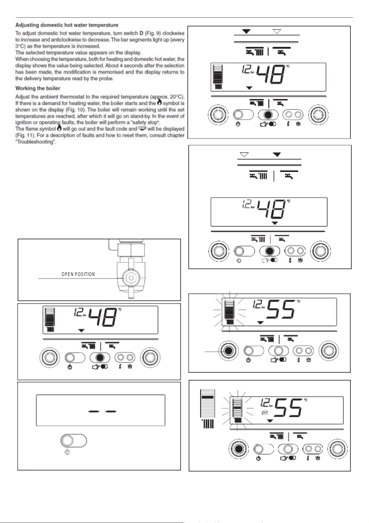
Adjusting domestic hot water temperature
To adjust domestic hot water temperature, turn switch D (&IG. 9) CLOCKWISE
to increase and anticlockwise to decrease. The bar segments light up
3—#) AS THE TEMPERATURE IS INCREASED.
The selected temperature value appears on the display.
7HEN CHOOSING THE TEMPERATURE, BOTH FOR HEATING AND DOMESTIC HOT WATER, THE
display shows the value being selected. About 4 seconds after the selection
has been made, the modification is memorised and the display returns to
the delivery temperature read by the probe.
Working the boiler
Adjust the ambient thermostat to the required temperature (approx. 2o—
#). If there is a demand for heating water, the boiler starts and the symbol
is shown on the display (&IG. 1o). The boiler will remain working until the
set temperatures are reached, after which it will go on stand-by. In the
event of ignition or operating faults, the boiler will perform a “safety stop
The flame symbol will go out and the fault code and will be displayed
(&IG. 11). &OR A DESCRIPTION OF FAULTS AND HOW TO RESET THEM, CONSULT CHAPTER
“Troubleshooting”.
2
3
6
A
Page 11

Page 12

EXCLUSIVE GREEN HE C.S.I. - R.S.I.
12
10
D
11
12a
12b
Tap closed
11
SWITCHING OFF
Switching off for short periods
&OR BRIEF ABSENCES PRESS THE
SHOW TWO SEGMENTS IN THE CENTRAL AREA (&IG. 12A). 7HEN THE BOILER REMAINS
powered with the gas tap open, it is protected by the following systems:
-
anti-freeze: when the temperature of the water in the boiler falls below safety
values, the circulator and the burner work at minimum power to increase
the water temperature to a safe value (35—#). The symbol lights up on
the display.
-
circulator anti-block: one operating cycle is performed every 24 hours.
Switching off for long periods
&OR PROLONGED ABSENCES PRESS THE BUTTON TO SWITCH OFF THE BOILER (&IG.
3). The display will show two segments in the central area. Turn the main
switch to “off”.
4URN OFF THE GAS TAP UNDER THE BOILER BY TURNING IT CLOCKWISE (&IG. 12B).
In this case, the anti-freeze and anti-block systems are disabled. Empty
the water circuit or suitably protect it with a good make of anti-freeze.
button to switch off the boiler. The display will
Page 13

ENGLISH
13
INF2 list
Step
Description
Display
2 digits
Display
4 digits
1 Input probe temperature
xx
01 —#
2 Return probe temperature
xx
02 —#
3 &IRST SANITARY PROBE TEMPERATURE (*)
xx
03 —# 4
Not used in this model
xx
Cond
—# 5
FUMES PROBE TEMPERATURE
xx (**)
05 6
Second heating system probe temperature
xx
06 —# 7
Domestic hot water flow rate (***)
xx
07
l/min
8
Ventilator speed /100
xx
&!. 9
Not used in this model
xx
09
10
Not used in this model
xx
10
11
Exchanger cleaning counter status
bH
xxxx
12-19
Historic alarm codes
xx
HIS0-HIS7
Note (*): if the SAN probe is faulty or disconnected, in the place of the value “- -” is displayed.
(**): if the display also shows the dot (.), the temperature of the fumes probe is 100+displayed value
(***):
IF THE mOW RATE IS
>1o
L/MIN # !
X L/MIN WHERE ! = 1o n " = 11 n # = 12
APPEARS ON THE DISPLAY
13
14
16
12
Boiler functions
Semi-automatic filling
The boiler features a semi-automatic filling device which turns on by pressing
the
button when the corresponding symbol is shown on the display
(&IG. 13).
If this condition occurs it means that the system is incorrectly pressurised
though the boiler will continue to work regularly. Press the circuit filling button
Press the circuit filling button a second time to interrupt the filling sequen-
ce. During filling, the drops of the circuit filling symbol and the growing
pressure value appear on the display in a cascade sequence.
After filling, the symbol is displayed for a few moments and then turns off.
Note
$URING lLLING, THE BOILER DOES NOT PERFORM OTHER FUNCTIONS. &OR EXAMPLE, IF
there is a request for domestic hot water, the boiler is unable to provide it
until filling has finished.
Note
If circuit
(&IG. 14); IF IT FALLS BELOW A MINIMUM SAFETY VALUE (o.3 BAR), FAULT CODE 41
APPEARS ON THE DISPLAY (&IG. 15) FOR A CERTAIN TIME, FOLLOWING WHICH, IF THE
fault persists, fault code 40 is displayed (see chapter on “Troubleshooting”).
In the event of fault 40, press to reset and then to start filling the circuit.
After fault 40 has been resolved, the boiler will carry out an automatic vent
CYCLE LASTING FOR ABOUT 2 MINUTES: THE WORDING h3&v WILL APPEAR ON THE DISPLAY
(&IG. 16) AND THE hFUNCTION SELECTION INDICATORSv will light up in sequence.
Press button to stop the automatic vent cycle.
to start-up the filling sequence.
pressure
reaches 0.6 bar, the
pressure
value flashes on the display
If you have to fill the system several times, contact the Technical Service
Centre to check whether the heating circuit is watertight (see if there are
15
any leaks).
Information
Press , THE DISPLAY TURNS OFF AND JUST THE WORD )N&/ APPEARS (&IG. 17). 0RESS
the button to view operating information. Press the button again to move
on to the next piece of information. If the button is not pressed, the system
automatically exits the function.
INF2
It is possible to display information, which may be useful for the Technical Assistance Centre, by pressing the button
appears on the display.
for 10 seconds: the code “INF2”
Page 14

EXCLUSIVE GREEN HE C.S.I. - R.S.I.
14
21
20
17
18
19
13
Info 0 -
SHOWS THE WORD )N&/ (&IG. 17)
Info 1 - only with the external probe connected, displays external temperature
(E.G. 12—#) (&IG. 18). 4HE VALUES SHOWN ON THE DISPLAY RANGE BETWEEN -
3o—# AND 35—#. "EYOND THESE VALUES THE DISPLAY SHOWS h- -v
Info 2 -
SHOWS CIRCUIT PRESSURE (&IG. 19)
Info 3 -
SHOWS THE SET HEATING TEMPERATURE (&IG. 2o)
Info 4 -
SHOWS THE SETTED TEMPERATURE (ONLY WATER TANK WITH SENSOR, &IG. 21)
Info 5 - displays the set heating temperature, in reference to the second
circuit, only if it is connected.
S.A.R.A. function (Fig. 21)
If the “winter” mode is selected, the S.A.R.A. (Automatic Ambient
Adjustment System) function can be activated.
Turn the heating water temperature selector to a temperature ranging
55 AND 65—#.
The S.A.R.A. self-adjustment system activates: depending on the temperature
set on the ambient thermostat and the time taken to reach it, the boiler au-
tomatically adjusts the heating water temperature to reduce operating times,
thereby increasing operating comfort and energy saving.
21
Page 15

ENGLISH
15
FAULT
Alarm ID
Symbol
Symbol
&,!-% &!),52%
",/#+
($) 10
YES ./
0!2!3)4% &,!-% (4)
11
./ YES
2%-!44%-04 ). 02/'2%33 (4) 12
./ ./
MINIMUM GAS INPUT PRESSURE (T)
13
./ YES
MINIMUM GAS INPUT PRESSURE (D)
14
YES ./
,)-)4 4(%2-/34!4 ($)
20
YES ./
3(/24
#)2#5)4 &5-%3 02/"% ($) 21
YES
YES
-!8)-5-
4%-0%2!452% ).054 02/"% ($)
24
YES ./
-!8)-5-
4%-0%2!452% ).054 02/"% (4)
25
./ YES
-!8)-5-
4%-0%2!452% 2%452. 02/"% ($)
26
YES ./
-!8)-5-
4%-0%2!452% 2%452. 02/"% (4)
27
./ YES
2%452.-).054 02/"% $)&&%2%.4)!, ($)
28
YES
YES
&5-%3 02
/"% /
6%2
4%-0%2!
452% (D)
29
YES
YES
6%.4),!4/2
(CYCLE START)
($)
34
YES ./
6%.4),!4/2 ). #9#,%
(LOW NUMBER OF REVOLUTIONS)
($)
37
YES
YES
).35&&)#)%.4 3934%- 02%3352% ($*)
40
YES ./
).35&&)#)%.4 3934%- 02%3352% (4*)
41
./ YES
7!4%2 02%3352% 42!.3$5#%2 ($) 42
YES
YES
%,%#42/.)#
"/!2$
($) 50-59
YES
YES
3!.)4!29 02/"%
1 (4—)
60
./ YES
3(/24 #)2#5)4//0%. 02)-!29 02/"% ($)
70
YES
YES
-!8)-5-
4%-0%2!452% ).054 02/"% (4)
71
./ ./
3(/24 #)2#5)4//0%. 2%452. 02/"% ($)
72
YES
YES
3%#/.$ 3934%- 7)4(/54 (%!4).' 02/"%
75
./ YES
,/7
4%-0%2!
452% 4(%2-/34!4 (4) 77
./ YES
).054/2%452. $)&&%2%.4)!, (4) 78
./ YES
).054/2%452. $)&&%2%.4)!, ($) 79
YES ./
3934%- !./-!,9
($)
80
YES
YES
3934%- !./-!,9
(4)
81
./ YES
3934%- !./-!,9
($)
82
YES
YES
3934%- !./-!,9
(4)
83
./ YES
CLEAN PRIMARY EXCHANGER (-)
91
./ YES
Temporary
Permanent
14
12
- TROUBLESHOOTING
7HEN A FAULT APPEARS ON THE DISPLAY, THE mAME SYMBOL
SEPAR
ATELY. &OR A
DESCR
IPTION OF THE F
AULTS, CONSULT THE F
goes out, a flashing code is shown and the two symbols and appear either together or
OLLO
WING TABLE.
(D) - Permanent - (T) - Temporary. In this operating status the boiler attempts to eliminate the fault on its own
(°) #.3.). - &AULT IN DOMESTIC HOT WATER CIRCUIT SENSOR - 6o: THE BOILER WORKS REGULARLY BUT DOES NOT ENSURE THE STABILITY OF THE HOT WATER TEMPERATURE WHICH,
HOWEVER, IS DELIVERED AT A TEMPERATURE OF APPROXIMATELY 5o—#. 4HE FAULT CODE IS ONLY DISPLAYED IN STANDBY. 2.3.). - /NLY WITH EXTERNAL WATER TANK
WITH
sensor. The fault code is shown when the boiler is in stand-by.
(*) If these two errors occur, check the pressure indicated on the water gauge. If the pressure is insufficient (< 0,4 bar, red area), proceed with the filling
OPERATIONS DESCRIBED IN THE CHAPTER h&ILLING AND EMPTYING THE SYSTEMSv. )F THE SYSTEM'S PRESSURE IS SUFlCIENT (> o,6 BAR, BLUE AREA) THE MALFUNCTION IS
caused by a lack of water circulation. Contact the Technical Assistance.
If alarm 21 code is temporarily displayed at ignition (with flame burning) this does not indicate a fault. Check the above table if the alarm persists.
Resetting faults
7AIT
FOR
ABOut
Then proceed as follows:
1)
Viewing just the symbol
If disappears, it means that an operating fault has been discovered which
the boiler is attempting to solve on its own (temporary stoppage). If the boiler
does not resume normal operation, two things may happen:
Case A (Fig. A)
disappears, the symbol and a different alarm code appear. In this
case, proceed as described in point 2.
Case B (Fig. B)
and a different alarm code are displayed together with .
In this case, proceed as described in point 3.
Case C
Alarm 91 - Contact the Technical Assistance
The boiler has a self-diagnosis system which, on the basis of the hours to-
talised in particular operating conditions, signals the need for maintenance
or cleaning of the primary exchanger (alarm code 91). After cleaning using
the kit supplied as an accessory, reset the hour counter as follows:
-
disconnect the mains power supply
-
remove the screws and hooks securing the electrical cover
-
remove connector J13 (see wiring diagram)
-
power the boiler and wait for alarm 13 to appear on the display
-
disconnect the power supply and reconnect connector J13
-
put back the electrical cover and restart the boiler
N.B.: perform the counter reset procedure every time the primary exchanger
is thoroughly cleaned or replaced.
10 seconds before resetting operating conditions.
fault
fault
Page 16

EXCLUSIVE GREEN HE C.S.I. - R.S.I.
16
F
G
Temporary
fault
Permanent
fault
15
2)
Viewing just the symbol (Fig. C)
Press the button to reset the appliance. If the boiler starts the ignition
phase and resumes normal operation, it may have stopped by accident.
If these stoppages should continue, contact the Technical Assistance Centre.
3)
Viewing the and symbols (Fig. D)
Contact the Technical Assistance Centre.
Note (C.S.I.)
&AULT IN DOMESTIC HOT WATER CIRCUIT SENSOR - 6o: THE BOILER WORKS REGULARLY BUT
does not ensure the stability of the hot water temperature which, however,
IS DELIVERED AT A TEMPERATURE OF APPROXIMATELY 5o—#. 4HE FAULT CODE IS
ONLY
displayed in standby.
13
- PROGRAMMING PARAMETERS
This boiler incorporates a new generation of electronic boards that, by setting/
modifying operating parameters, allow the boiler to be personalised to satisfy
various system and/or user requirements.The programmable parameters are
shown in the table on the next page.
4HE PARAMETERS MUST BE PROGRAMMED WITH THE BOILER IN THE /&& POSITION.
To do this, press the
During parameter modification operations, the “select functions” button
acts as an ENTER (confirm) button, the button acts as an ESCAPE
(escape) button. If no confirmation is given within 10 seconds, the value
is discarded and returns to the previously set one.
BUTTON UNTIL THE DISPLAY SHOWS h- -v (&IG. %).
Setting the password
Press and hold down the select functions button and the button together
FOR ABOUT 1o SECONDS. 4HE DISPLAY WILL LOOK LIKE &IG. &. %NTER THE PASSWORD FOR
accessing the parameter modifications function by turning the domestic hot
water temperature selector to obtain the required value. The password for
accessing the parameter programming function is located on the back side
of the control panel. Confirm by pressing ENTER.
Modifying parameters
4URN THE DOMESTIC HOT WATER TEMPERATURE SELECTOR (&IG. ') TO SEQUENTIALLY
scroll the two-figure codes of the parameters indicated in the table. After
identifying the parameter you wish to modify, proceed as follows:
- PRESS %.4%2 TO ACCESS THE PARAMETER MODIlCATION FUNCTION. 7HEN %.4%
IS PRESSED, THE PREVIOUSLY SET VALUE STARTS mASHING (&IG.()
-
turn the domestic hot water temperature selector to change the value
-
press ENTER to confirm the new value. The digits stop flashing
-
press ESCAPE to exit.
4HE BOILER RETURNS TO THE h- -v (/&&) STATUS.
To reset, press the
E
BUTTON (&IG. %).
2
Page 17

ENGLISH
23
N.
PARAMETERS DESCRIPTION
PAR.
UNIT OF
MEASURE
MIN
MAX
DEFAULT
(1)
(2)
1
4()3 0
!2!-%4%2 )3 ./4
53%$ /. 4()3 -/$%,. $/ ./4
-/$)&9
1
2
-)./2
0!2!-%4%2
10-16-20-26-30-34-50-70
26 (25K7)-34 (35K7)
3
).35,!4)/.
,%6%,
/& "5),$).'
min
5 20
5
10
$(7 -/$%
1 - Instantaneous
2 - Mini-tank
3 - External water- tank with thermostat
4 - External water- tank with sensor
5 - DS integrated water tank
6 3S integrated water tank
1
11
$(7
#)2#5)4
-!8)-5-
3%4-0/).4
—# 40 60
60
12
4()3 0
!2!-%4%2 )3 ./4
53%$ /. 4()3 -/$%,. $/ ./4
-/$)&9
60
13
4()3 0
!2!-%4%2 )3 ./4
53%$ /. 4()3 -/$%,. $/ ./4
-/$)&9
80
14
4()3 0
!2!-%4%2 )3 ./4
53%$ /. 4()3 -/$%,. $/ ./4
-/$)&9
5
20
(%!4).' -/$%
o - /&&
1 - /.
2 - :ONE VALVES + REMOTE CONTROL PANEL
3 -
#/..%#4 !0
4 - Not used
5 - Not used
6
- #/..%#4 !4/"4
7 2%-/4% #/ .42/,+#/..%#4 !4/"4
8 2%-/4% 0!.%, + :/.% 6!,6%3
1
21
(%!4).'
#)2#5)4
-!8)-5-
3%4-0/).4
—# 40
80
80
22
-).)-5- (%!4).'
3%4
0/).4
C 20
39
20
23
-!8)-5-
(%!4).' 6%.4),!4/2
30%%$
revs/min
G20 G31
25 K7 6o 6o
35 K7 6o 59
MAX
24
-).)-5-
(%!4).' 6%.4),!4/2
30%%$
revs/min
G20 G31
25 K7 12 19
35 K7 12 19
MIN
25
$)&&%2%.4)!,
(%!4).'
0/3)4)6%
—#
2 10
6
26
$)&&%2%.4)!,
(%!4).'
.%'!4)6%
—# 2 10
6
28
-!8 (%!4).'
0/7%2 2%$5#4)/. 4)-%2
min 0
20
15
29
&/2#%$
(%!4).'
3(54
$/7.
4)-%2
min 0
20
5
30
(%!4).'
4)-%2
2%3%4
&5.#4)/.
- o
(./)
1 (YES)
0
31
-!8)-5- (%!4).'
3%4
0/).4
2#(
()) CIRCUIT)
—# 40
80
45
32
-).)-5- (%!4).'
3%4
0/).4
2#(
()) CIRCUIT)
—# 20
39
25
40
$(7 4(%2-/34!4 /0%2!
4).' -/$%
o - /&&
1 - !54/
2 - /.
1
41
4()3 0
!2!-%4%2 )3 ./4
53%$ /. 4()3 -/$%,. $/ ./4
-/$)&9
1
42
3.!.2.!. &5.#4)/.
o - /&&
1 - !54/
1
43
4()3 0
!2!-%4%2 )3 ./4
53%$ /. 4()3 -/$%,. $/ ./4
-/$)&9
1
44
4(%2-/2%'5,!4)/. &5.#4)/.
o - /&&
1 - !54/
1
45
).#,).!4)/. 4(%2-/2%'5,!4)/.
#526%
(/4#)
2,5 40
20
46
4(%2-/2%'5,!4)/. &5.#4)/. 2#(
-
o - /&&
1
- !54/
1
47
).#,).!4)/. 4(%2-/2%'5,!4)/.
#526%
(/4#) 2#(
2,5
40
10
48
4()3 0
!2!-%4%2 )3 ./4
53%$ /. 4()3 -/$%,. $/ ./4
-/$)&9
-
-
50
4()3 0
!2!-%4%2 )3 ./4
53%$ /. 4()3 -/$%,. $/ ./4
-/$)&9
1
51
HEAT REQUEST TYPE CH1 (I circuit)
-
0 1
0
52
HEAT REQUEST TYPE CH2 (II circuit)
-
0 1
0
61
$(7
!.4)&2%%:%
&5.#4)/.
4%-0%2!452%
(/.)
—#
0 10
4
62
(%!4).'
!.4)&2%%:% &5.#. $%,)6%29 4%-0.
(/.)
—#
0 10
6
63
4()3 0
!2!-%4%2 )3 ./4
53%$ /. 4()3 -/$%,. $/ ./4
-/$)&9
6
65
%84%2.!, 3%.3/2 2%!#4)6)49
0 (very fast) 255 (very slow)
20
85
3%-)-!54/-!
4)# &),,).'
0 - Disabled
1 - Enabled
1
86
!54/-!
4)# &),,).' 02%3352% (/.)
bar
0.4 1.0
0.6
87
4()3 0
!2!-%4%2 )3 ./4
53%$ /. 4()3 -/$%,. $/ ./4
-/$)&9
-
90 ADJUSTABLE SPEED PUMP
0 100
41
92 %.!",% 0/34
-#)2#5,!
4)/. &2/-
$(7 4/
(%!
4).'
0 1
0
93 $52!
4)/. /& 0/34
-#)2#5,!
4)/. &2/-
$(7 4/
(%!
4).'
1 255
5
94 05-0
). #/.4).5!,
-/$% #(1 (#)2#5)4 1)
0 1
0
95 05-0
). #/.4).5!,
-/$% #(2 (#)2#5)4 2)
0 1
0
17 16
PROGRAMMABLE PARAMETERS HE C.S.I.
* 4HE VALUE IS EXPRESSED ON THE DISPLAY IN REVS/MIN/1oo (EXAMPLE 3.6oo = 36).
Some default values could be different from the one in the table, dependent on the status of data sheet updating
1
Setted in factory
2
Settede by technical assistan
3
4
5
6
Page 18

EXCLUSIVE GREEN HE C.S.I. - R.S.I.
24
D
17
16 - SETTING THE THERMOREGULATION – OPTIONAL with use of external sensor
Checking the connection with the external probe
!FTER CONNECTING THE EXTERNAL PROBE TO THE BOILER, USE THE ).&/ FUNCTION TO CHECK THAT THE PROBE HAS BEEN AUTOMATICALLY RECOGNISED BY THE TEMPERATURE
control card. Immediately after installation, the value read by the probe may very well be higher then that measured by a reference probe.
%NABLE AND OPTIMISE THE 4(%2-/2%'5,!4)/. FUNCTION BY SETTING THE FOLLOWING PARAMETERS:
PARAMETER
490%
/& "5),$).'
-!8)-5- (%!4).'
-).)-5- (%!4).'
%.!",% 4(%2-/2%'5,!4)/.
&5.#4)/.
/&&3%4 4%-0%2!452% #526%
490% /& (%!4 2%15%34
3%4
3%4
0/).4
0/).4
To access the programming mode, consult “Programming parameters”.
PARAMETER 03. Type of building
3
21
22
44
45
51
In order to calculate delivery temperature, the temperature control system
does not directly use the external temperature value but considers the heat
insulation of the building: in well-lagged buildings, external temperature
variations affect the ambient temperature less than they do in badly-lagged
buildings. Use parameter 3 to set the heat insulation level of the building
according to the following scheme:
Type of building
New Old Hollow Solid
houses houses bricks bricks
A 19 14 12 8
B 20 16 15 11
C 19 15 14 9
D 18 12 10 5
Stones
PARAMETERS 21 and 22. Maximum and minimum delivery
temperature
These two parameters limit the delivery temperature automatically produced
BY THE
4%-0%2!452% #/.42/,
-!8)-5- $%,)6%294%-0%2!452% (-!8)-5- (%!4).' 3%4 0/).4)
while PARAMETER 22 determines MINIMUM DELIVERY TEMPERATURE
(-).)-5- (%!4).'
3%4
PARAMETER 44. Enable thermoregulation function
The connected external temperature probe combined with PARAMETER 44
provides the following operating modes:
%84%2.!, 02/"% #/..%#4%$
CASE THE 4%-0%2!452% #/.42/, FUNCTION IS DISABLED EVEN THOUGH THE
external probe is connected. The temperature read by the external probe
CAN ALWAYS BE VIEWED BY PRESSING THE ).&/ BUTTON. 4HE 4%-0%2!452%
#/.42/, SYMBOLS ARE NOT DISPLAYED.
%84%2.!, 02/"% #/..%#4%$, 0!2!-%4%2
THE 4%-0%2!452% #/.42/, FUNCTION IS ENABLED. 4HE TEMPERATURE READ
BY THE EXTERNAL PROBE AND THE 4%-0%2!452% #/.42/, SYMBOLS CAN BE
VIEWED BY PRESSING THE ).&/ BUTTON.
4HE 4%-0%2!452% #/.42/, FUNCTION CANNOT BE ENABLED UNLESS THE
external probe has been fitted and connected. In this case, PARAMETER
44 is ignored and has no effect on boiler operation.
PARAMETER 45. Choosing the offset temperature curve (graph 1)
The offset heating curve maintains a theoretical ambient temperature of
2o—# AT EXTERNAL TEMPERATURES RANGING FROM +2o—# TO -2o—#. 4HE CHOICE
OF
the curve depends on the rated minimum external temperature (on the ge-
ographical area, therefore) and the rated delivery temperature (on the type
of system, therefore) and must be carefully calculated by the fitter using the
following formula:
0. 45 = 1o X
FUNCTION.
0/).4).
AND
0!2!-%4%2
rated delivery T - 20 20-
rated min. external T
0!2!-%4%2 21
44 = o
44 = 1
(/.)
DETERMINES
(/&&)
IN THIS
IN THIS CASE
AVAILABLE IN THE PROGRAMMING MODE
).34!,,!4)/. !.$ #!,)"2!4)/.
).34!,,!4)/.
).34!,,!4)/.
).34!,,!4)/.
).34!,,!4)/. !.$ #!,)"2!4)/.
).34!,,!4)/.
If, from your calculations, you obtain an intermediate value between two
curves, we suggest choosing the compensation curve closest to the value
obtained.
Example: if the value obtained from the calculations is 8, this is between
curve 7.5 and curve 10. In this case, choose the closest curve, which is 7.5.
PARAMETER 51. Type of heat request
IF AN AMBIENT THERMOSTAT IS CONNECTED TO THE BOILER, SET
PARAMETER 51 = 0 (graph 2).
The ambient thermostat makes a heat request when its contact closes, while
it stops it when its contact opens. Though delivery temperature is automati-
cally calculated by the boiler, the user may manually override it. By modifying
(%!4).' ON THE USER
AVAILABLE BUT JUST A VALUE THAT CAN BE SET FROM +5 TO -5—# AS REQUIRED.
-ODI-
fications to this value do not directly change delivery temperature but affect
the calculation made to automatically determine its value by modifying the
REFERENCE TEMPERATURE OF THE SYSTEM (o = 2o—#).
&OR
BOILERS lTTED WITH THE 3
remains closed for a long time, the boiler automatically increases the delivery
temperature which is added to the effect of the temperature control function.
7HEN THE !-")%.4 4(%2-/34!4 OPENS, THE BOILER AUTOMATICALLY RETURNS
TO THE VALUE DETERMINED BY THE
IF A PROGRAMMABLE TIMER IS CONNECTED TO THE BOILER, SET
PARAMETER 51 = 1 (graph 3).
7HEN THE CONTACT IS CLOSED, THE HEAT REQUEST IS MADE BY THE DELIVERY PROBE ON
the basis of the external temperature in order to maintain the rated ambient
TEMPER
ATURE AT THE $!9 LEVEL (2o—#). 7HEN THE CONTACT OPENS, IT DOES NOT
stop the heat request but reduces (parallel shift) the temperature curve to the
.)'(4 LEVEL (16—#). 4HOUGH DELIVERY TEMPERATURE IS AUTOMATICALLY CALCULATED
by the boiler, the user may manually override it.
"Y
MODIFYING
WILL NO LONGER BE AVAILABLE BUT JUST A VALUE THAT CAN BE SET FROM +5 TO
n5—#
as required.
Modifications to this value do not directly change delivery temperature but
affect the calculation made to automatically determine its value by modifying
THE REFERENCE
FOR
NIGHT level).
CONNECT AT/BT
)N CASE OF USING #/..%#4 !4/"4, ACCESSORY SUPPLIED ON REQUEST, THE BOILER
gives the possibility to choose 2 thermoregulation curves:
- /4# 1 #( (PARAMETER 45) FOR A
- /4# 2 #( (PARAMETER 47) FOR A
Even in case of second circuit (2CH) the curve depends on the external
minimum project temperature (on the geographical area, therefore) and on
the delivey project temperature (on the type of system, therefore); the installer
0. 47 = 1o X
must to put attention to calculate it using the following formula:
Parameters 31 and 32 give the possibility to define the maximum and the
minimum central heating set-point of the second circuit.
To correct the curve in this configuration, please refer to the instructions
supplied with the accessory.
INTERFACE,
(%!4).'
ON THE USER INTERFACE, THE
TEMPERATURE
& 3%26)#%
& 3%26)#%
THE (%!4).' 3%4 0/).4
WILL
.!.2.!. &UNCTION, IF THE !-")%.4 4(%2-/34!4
4%-0%2!452% #/.42/,
(%!4).'
OF
THE
SYSTEM
(o = 2o—#
DIRECT SYSTEM
MIXED
SYSTEM.
FOR
rated delivery T - 20
20- rated min. external T
NO
LONGER
FUNCTION.
3%4
$!9
LEVEL;
BE
0/).4
16—#
Page 19

ENGLISH
25
ATION
100
GRAPH 1
Thermoregulation curves
40 35 30 27,5 25 22,5
20
90
17,5
80
70
15
P.21
12,5
60
10
50
7,5
40
5
30
2,5
P.22
GRAPH 3
Parallel night
DAY
temperature curve
NIGHT
temperature curve
30
20
10
20 15 10 5 0 -5 -10 -15
EXTERNAL TEMPERATURE (°C)
GRAPH 2
Temperature curve correction
90
80
70
60
50
40
30
20
10
30 25 20 15
-5 -10 -15
EXTERNAL TEMPERATURE (°C)
Condensing boiler
Gas type:
Gas category:
Serial N.
80-60 °C 80-60 °C 50-30 °C
set at:
DELIVERY TEMPERATURE (°C)
DELIVERY TEMPERATURE (°C)
DELIVERY TEMPERATURE (°C)
18
EXTERNAL TEMPERATURE (°C)
37,5 32,5
17
- SERIAL NUMBER PLATE
$(7
OPER
Qn nominal capacity
Pn nominal power
IP protection level
P. min minimum pressure
Pmw
Pms CH maximum pressure
T temperature
working efficiency
D specific capacity
NOx
18
CH operation
$(7 MAXIMUM PRESSURE
./X VALUE CLASS
D: l/min
+5˚C
0˚C
- ADJUSTMENTS
The boiler has already been factory adjusted by the manufacturer. If a new
adjustment is required, for example, after extraordinary maintenance, repla-
cing the gas valve or converting from natural gas to LPG, proceed as follows.
Maximum and minimum power, minimum and maximum heating,
must be adjusted in the indicated sequence by qualified staff.
- UNSCREW THE LOWER COVER lXING SCREW (#, &IG. 1.4)
-
0ULL THE COVER TOWARDS YOU AND REMOVE (!-") (&IG. 1.5)
-
,OOSEN THE TWO lXING SCREWS ($) AND REMOVE THE SHELL (&IG. 1.2)
-
Lift up the panel and turn it forwards
-
Loosen the pressure tap screw downline from the gas valve by about two
turns and connect the pressure gauge to it
#!,)"2!4)/.
IN THE /&& POSITION.4O DO THIS, PRESS THE button until the dis
h- -v (&IG. %).
& 3%26)#% OPERATIONS MUST BE PERFORMED WITH THE BOILER
pla
y s
how
s
During parameter modification operations, the “select functions” button
acts as an ENTER (confirm) button, the button acts as an ESCAPE
button. If no confirmation is given within 10 seconds, the value is discar-
ded and returns to the previously set one.
Setting the password
Press and hold down the operating mode button and the button together
FOR ABOUT 1o SECONDS. 4HE DISPLAY WILL LOOK LIKE &IG. &.
Enter the password for accessing the parameter modifications function by
turning the domestic hot water temperature selector to the required value.
The password is located on the back side of the control panel. Confirm by
pressing ENTER.
Calibration phases
4URN
THE
DOMESTIC
& 3%26)#%
1
gas type (don’t modify this parameter)
2
boiler power (minor parameter)
3
insulation level of building (only if external sensor is connected)
HOT WATER SELECTOR
PHASES:
TO
SEQUENTIALLY
10 domestic hot water mode (Exclusive Green HE CSI: do not modify this
parameter)
45 INCLINATION OF THERMOREGULATION CURVE (/4#), ONLY IF EXTERNAL SENSOR IS
connected)
47
INCLINATION OF THERMOREGULATION CURVE 2#( (/4#), ONLY IF EXTERNAL SENSOR
is connected)
HP maximum fan speed (do not modify this parameter)
LP minimum fan speed (do not modify this parameter)
SP ignition speed (do not modify this parameter)
HH boiler at maximum power
LL boiler at minimum power
MM fan ignition speed (do not modify this parameter)
23
maximum heating adjustment possibility (do not modify this parameter)
24
minimum heating adjustment possibility (do not modify this parameter).
The parameters 10 - HP - SP - LP - MM - 23 - 24 must be modified,
by professionally qualified personnel, only if absolutely necessary.
The manufacturer refuses any responsibility in the case of incorrect
setting of the parameters.
MAXIMUM VENTILATOR SPEED (P. HP)
-
Select parameter HP
-
Press the ENTER button, then modify the value of the parameter by turning
the sanitary water temperature selector. The maximum speed of the fan is
linked with the type of gas and the power of the boiler, table 1
-
Turn the sanitary water temperature selector in order to adjust the set value
-
Confirm the new value you have set by pressing ENTER.
The value indicated on the display is expressed in revs min/100 (example
36oo = 36).
The value set during this operation automatically modifies the maximum
value of parameter 23.
SCROLL
THE
#!,)"2!4)/.
Page 20

EXCLUSIVE GREEN HE C.S.I. - R.S.I.
26
2 2 2
G20
G31
25 C.S.I.-R.S.I.
60 60
rpm
35 C.S.I.-R.S.I.
60 59
rpm
G20
G31
25 C.S.I.-R.S.I.
12
19
rpm
35 C.S.I.-R.S.I.
12
19
rpm
G20
G31
25 #.3.).-2.3.). -
#/2 max
9,0
10,0 %
35 #.3.).-2.3.). -
#/2 max
9,0
10,0 %
G20
G31
25 #.3.).-2.3.). -
#/2 min
9,5
10,0 %
35 #.3.).-2.3.). -
#/2 min
9,5
10,0 %
19
MINIMUM VENTILATOR SPEED (P. LP)
-
Select parameter LP
-
Press the ENTER button, then modify the value of the parameter by turning
the sanitary water temperature selector. The minimum speed of the fan is
linked with the type of gas and the power of the boiler, table 2
-
Turn the sanitary water temperature selector in order to adjust the set value
-
Confirm the new value you have set by pressing ENTER.
The value indicated on the display is expressed in revs min/100 (example
36oo = 36).
The value set during this operation automatically modifies the maximum
value of parameter 24.
VENTILATOR IGNITION SPEED (P. SP)
-
Select parameter SP
-
Press the ENTER button, then modify the value of the parameter by turning
the sanitary water temperature selector. The standard slow start value is
3700 revs/min (25HE) - 3300 revs/min (35HE)
-
Confirm the new value you have set by pressing ENTER.
MAXIMUM POWER ADJUSTMENT (P. HH) (Fig. 1.17)
- 4URN THE BOILER /&&
- Select the parameter HH and wait for the boiler to come on
- #HECK
THAT THE
MAXIMUM
#/
reading on the analyser (see paragraph
“Checking combustion parameters”) corresponds with the values indicated
in table 3.
)F THE
#/2 proves to comply with the values in the table, proceed to adjust the
next parameter (LL - adjusting the minimum), if different modify the value by
turning the maximum power adjustment screw with a screwdriver (clockwise
to decrease) until you obtain a value contained in table 3.
MINIMUM POWER ADJUSTMENT (P. LL) (Fig. 1.17)
- 3ELECT THE PARAMETER ,, (WITH THE BOILER STILL /&&) AND WAIT FOR THE BOILER
to come on.
- #HECK THAT THE MINIMUM #/ reading on the analyser (see paragraph
“Checking combustion parameters”) corresponds with the values indicated
in table 4.
)F THE #/ proves to be different from the values in the table, proceed to
adjust the parameter by turning the maximum power adjustment screw after
having unscrewed the protective cap (clockwise to increase) until you obtain
a value contained in table 4.
IGNITION SPEED (P. MM)
-
Select parameter MM.
The boiler starts at the slow ignition speed.
-
Turn the heating water selector to increase or decrease the fan speed.
MINIMUM HEATING ADJUSTMENT POSSIBILITY (P. 24)
-
Select parameter 24
-
Press the ENTER button to access the parameter value modification
function
-
Turn the sanitary water selector to modify the minimum fan speed
-
Confirm the value you have set by pressing ENTER.
%XIT THE
4HE BOILER RETURNS TO THE h- -v (/&&) STATUS.
#!,)"2!4)/.
& 3%26)#%
FUNCTION BY PRESSING
%3#!0%.
To reset, press the button.
-
Disconnect the pressure gauge and tighten the pressure tap screw.
RANGE RATED MAXIMUM OUTPUT CH (FAN SPEED) - 23
Select the parameter 23 by turning the encoder. Push ENTER button and
modify the maximum fan speed as indicated in the range rated table by
turning the encoder. Push ENTER button to store the alue. The values just
setted must be recorded on the last page of this manual.
After adjusting the gas valve, seal it with sealing wax.
After making adjustments:
-
return the temperature set with the ambient thermostat to the
required
position
-
close the panel
-
put back the shell.
19
- GAS CONVERSION
It is easy to transform gas from one family to gas belonging to another family
even with the boiler installed.
This job must be done by professionally qualified personnel only.
4HE BOILER IS SUPPLIED TO RUN ON NATURAL GAS ('2o) n SEE THE PRODUCT RATING
plate for details.
The boiler can be transformed to use propane gas using a special kit.
&OLLOW THE INSTRUCTIONS GIVEN HERE BELOW FOR DISASSEMBLY:
-
Switch off the power to the boiler and turn off the gas cock
-
Remove the panel and casing
-
Lift up and rotate the instrument panel
- /PEN THE AIR BOX COVER
Table 1
MAXIMUM NUMBER OF FAN REVOLUTIONS
Table 2
MINIMUM NUMBER OF FAN REVOLUTIONS
Table 3
Table 4
&OR 25 HE only: unscrew the screws fastening the silencer (A) and remove
it (Fig. 1.18)
- Disconnect the mixer gas ramp. Unscrew the clamp screws and relative
mixer springs to fan and then remove it.
- &OR HE 35 only: unscrew the screws fixing the plastic Venturi to the alu-
minium shell
-
Loosen the plastic Venturi (B) - Fig. 1.18 - by levering from under the teeth
("% #!2%&5, ./4 4/ &/2#% 4(%-) AND PRESS FROM THE OPPOSITE SIDE
until it is completely extracted from the aluminium shell.
-
Using wrench CH6 remove and DISGARD AND DO NOT RE-USE the 2
nozzles (C), clean plastic debris from relative housing (Fig. 1.20)
-
Press in the 2 new nozzles from the kit as far as the threaded part, then
screw in tightly
-
Reassemble the mixer with the flap in a horizontal position and the spacer
SPRINGS PLACED AT 12o— AS SHOWN IN THE
-
Reassemble gas ramp and silencer, working vice versa.
-
Check the number of times the fan turns
-
Switch on the power to the boiler and turn on gas cock again
- &ILL IN AND STICK ON THE ACCOMPANYING TRANSFORMATION DATA LABEL
-
Close the air box cover
-
Close up the instrument panel again
-
Reassemble the casing and panel
(Fig. 1.20)
Programme the “Gas type” parameter and regulate the boiler following the
instructions in the “Adjustments” section.
Transformation must be done by qualified personnel only.
After completing transformation, regulate the boiler again following
instructions given in the specific paragraph and apply the new identi-
fication label from the kit.
General maintenance
Be particularly careful when handling the mixer: the Clapet juts out from the
body so that the mixer must be laid on the air inlet side (flap area) or make
sure the Clapet is inside the body if it has to be laid on the Clapet side.
The Clapet must never have to bear the weight of the mixer.
Clean the Venturi from any dust with an aspirator during the annual system
cleaning. Check that flap and Clapet are working correctly (all open at rated
flow, all closed at minimum flow)
20– CHECKING COMBUSTION PARAMETER
Do as follows to analyze combustion:
-
GO TO
'!5').'
as given in paragraph “Adjustments”
& 3%26)#%
-
insert the analyzer probe into the specific openings on the air box, after
removing screw B and cap C.
The fumes analysis probe must be introduced as far as possible
-
screw the analyzer setscrews into the fumes analysis opening
-
the first display gives the reading of the number of turns corresponding to
maximum heating power set on the boiler (see paragraph “Adjustments”
item P23)
After turning the domestic hot water temperature selector again the boiler
will ignite to check combustion
-
check combustion
-
refer to the “Adjustments” paragraph if the boiler has to be gauged
-
remove the analyzer gauge and close the combustion analysis openings
by their screws.
IMPORTANT
The function switching off the boiler when the water temperature reaches
MAXIMUM LIMIT OF ABOUT 9o—# WILL ALSO STAY ON DURING COMBUSTION ANALYSIS
AND SET THE COMBUSTION ANALYSIS PASSWORD
Page 21

ENGLISH
27
HTG f
an
speed
(r.p.m.)
Emissions COs.a. (ppM) G20
20
21 - MAINTENANCE
The appliance must be systematically controlled at regular intervals to make sure it works correctly and efficiently and conforms
to legislative provisions in force.
The frequency of controls depends on the conditions of installation and usage,
it being anyhow necessary to have a complete service check
carried out by A competent provider every year.
•
Check and compare the boiler's performance with the relative
specifications. Any cause of visible deterioration must be immediately identified and eliminated.
•
Closely inspect the boiler for signs of damages or deterioration,
particularly with the drainage and aspiration system and electrical
apparatus.
•
Check and adjust - where necessary - all the burner's parameters
The boiler is supplied with the settings shown in the table. But said values may be adjusted by following the graphs given here below,
depending on installation requirements or regional rules and regulations combusted gas emission limits.
190
180
170
160
150
140
130
120
110
100
90
80
70
60
50
40
30
20
10
0
2 4 6 8 10 12 14 16 18 20 22 24 26
Heat capacity curve – emissions (Qnrisc) – 25 HE
Heat capacity curve – fan rpm (Qnrisc) – 25 HE
6200
5800
5400
5000
4600
4200
3800
3400
3000
2600
2200
1800
1400
1000
2 4 6 8 10 12 14 16 18 20 22 24 26
•
Check and adjust - where necessary - the system's pressure.
•
Analyze combustion. Compare results with the product's
specifi- cation. Any loss in performance must be identified and
corrected by finding and eliminating the cause.
•
Make sure the main heat exchanger is clean and free of any
residuals or obstruction.
•
Check and clean - where necessary - the condensation
trap to make sure it works properly.
lMPORTANT: always switch off the power to the appliance
and close the gas by the gas cock on the boiler before
carrying out any maintenance and cleaning of the boiler.
Do not clean the appliance or any part with flammable substances
(e.g. petrol, alcohol, etc.).
Do not clean enameled and plastic parts with paint solvents.
Panels must be cleaned with ordinary soap and water only.
(HEATING HEAT CAPACITY (K7)
(HEATING HEAT CAPACITY (K7)
Page 22

EXCLUSIVE GREEN HE C.S.I. - R.S.I.
28
HTG f
an
speed
(r.p.m.)
Emissions
Cos.a.
.
(P.P
.M.)
G20
21
200
190
180
170
160
150
140
130
120
110
100
90
80
70
60
50
40
30
20
10
0
2 4 6 8 10 12 14 16 18 20 22 24 26 28 30 32 34 36
Heat capacity curve – emissions (Qnrisc) – 35 HE
(HEATING HEAT CAPACITY (K7)
6500
6000
5500
5000
4500
4000
3500
3000
2500
2000
1500
1000
2 4 6 8 10 12 14 16 18 20 22 24 26 28 30 32 34 36
Heat capacity curve – fan rpm (Qnrisc) – 35 HE
(HEATING HEAT CAPACITY (K7)
Page 23

ENGLISH
173
22
EXCLUSIVE GREEN Combi C.S.I. HE
BOILER OPERATING ELEMENTS
1
- Filling tap (C.S.I.)
2
- Pressure transducer
3 - Discharge valve
4 - Three-way solenoid valve
5 - Safety valve
6
- Circulation pump
7
- Lower air vent valve
8 - Hydrometer
9
- Siphon
10
- Return NTC sensor
11 - Fume probe
12 - Fume analysis sample cap
13 - Fumes outlet
14 - Silencier (25 HE only)
15 - Ignition transformer
16 - Upper air vent valve
17 - Delivery NTC sensor
18 - High limit thermostat
19 - Detection electrode
20 - Ignition electrode
21 - Condensate level sensor
22 - Burner
23 - Main exchanger
24 - Fan
25
- Mixer
26
- Expansion vessel
27 - DHW sensor (C.S.I)
28 - Domestic hot water exchanger (C.S.I.)
29 - Flowmeter C.S.I.)
30
- Gas valve
31
- Exhaust collector
[ES] - ELEMENTOS DE FUNCIONAMIENTO
DE LA CALDERA
1 - Tapón de llenado (C.S.I.)
2 - Transductor de presión
3
- Válvula de descarga
4
- Válvula solenoide de tres vías
5 - Válvula de seguridad
6
- Bomba de circulación
7
- Válvula de venteo inferior
8 - Hidrómetro
9
- Sifón
10
- Sensor NTC de retorno
11 - Sonda de humos
12 - Tapa de la muestra de análisis de humos
13 - Salida de humos
14
- Silenciador (solo 25 HE)
15
- Transformador de encendido
16 - Válvula de venteo superior
17 - Sensor NTC de entrega
18 - Termostato de límite
19 - Electrodo de detección
20 - Electrodo de encendido
21 - Sensor nivel condensado
22 - Quemador
23 - Intercambiador principal
24 - Ventilador
25
- Mezclador
26
- Vaso de expansión
27 - Sensor DHW (C.S.I)
28
- Intercambiador de agua caliente sanitaria (C.S.I.)
29
- Caudalímetro C.S.I.)
30 - Válvula del gas
31 - Colector de escape
[PT] - ELEMENTOS OPERACIONAIS DA CALDEIRA
1 - Tampa de enchimento (C.S.I.)
2 - Transdutor de pressão
3- Válvula de descarga
4- 6ÕLVULA SOLENOIDE DE TRãS VIAS
5 - Válvula de segurança
6 - Bomba de circulação
7 - Válvula do respiro de ar inferior
8 - Hidrómetro
9
- Sifão
10
- Sensor NTC de retorno
11 - Sonda de fumaça
12 - Tampa de amostra para análise de fumaça
13 - Saída de fumaça
14 - Silenciador (somente 25 HE)
15 - Transformador de ignição
16 - Válvula do respiro de ar superior
17 - Sensor NTC de envio
18 - Termóstato de limite alto
19 - Eléctrodo de detecção
20 - Eléctrodo de ignição
21 - Sensor de nível condensado
22 - Queimador
23 - Comutador principal
24 - Ventilador
25
- Misturador
26
- Vasilha de expansão
27 -
3ENSOR
$(7
28
- Comutador de água quente doméstica (C.S.I.)
29
- Medidor de fluxo (C.S.I.)
30 - Válvula de gás
31 - Colector de exaustão
HU] - A KAZAN FUNKCIONALIS ALKATRESZEI
1
- Tolto csap (C.S.I.)
2
- Nyomas transzduktor
3 - Leereszto szelep
4 - Haromallasu szoleonid szelep
5 - Biztonsagi szelep
6
- Keringeto szivattyu
7
- Als6 levego szellozo szelep
8 - Hidrometer
9
- Sziphon
10
- Visszatero NTC szenzor
11 - Fost pr6ba
12 - Fostelemzes minta kupak
13 - Fostok elvezetese
14
- Hangtompft6 (csak 25 HE)
15
- Gyujt6transzformator
(#.3.).)
16 - Felso levego szellozo stele
17 - Eloremeno NTC szenzor
18 - Felso limit termosztat
19 - Detektalas elektr6da
20 - Gyujt6elektr6d
21 - Kondenzatum szint szenzor
22 - Ego
23 - Fo hocserelo
24 - Ventilator
25 - Mixer
27 - Hasznalati melegvfz szenzor (C.S.I)
28 - Hasznalati melegvfz hocserelo (C.S.I.)
29 - Aramlasmero C.S.I.)
30
- Gaz szelep
31
- Eltavoz6 gyOjto
[RO] - ELEMENTELE FUNCJIONALE
ALE CENTRALEI
1 - Robinet de umplere (C.S.I.)
2 - Traductor de presiune
3
- Robinet de golire
4
- Electrovana cu trei cai
5 - Supapa de siguranta
6 - Pompa de circulatie
7 - Aerisitor la partea inferioara
8 - Hidrometru
9
- Sifon
10
- Senzor NTC de retur
11 - Senzor gaze arse
12 - Capac loca$ analiza gaze arse
13 - Ie$ire gaze arse
14 - Amortizor (numai 25 HE)
15 - Transformator de aprindere
16 - Aerisitor la partea superioara
17 - Senzor NTC de tur
18 - Termostat de limita
19 - Electrod de detectie
20 - Electrod de aprindere
21 - Senzor de nivel condens
22 - Arzator
23 - Schimbator principal
24 - Ventilator
25
- Mixer
26
- Vas de expansiune
27 - Senzor ACM (C.S.I)
28 - Schimbator apa calda menajera (C.S.I.)
29 - Debitmetru (C.S.I.)
30
- Vana de gaz
31
- Colector evacuare
[SI] - SESTAVNI DELI KOTLA
1
- Filling tap (C.S.I.)
2
- Pressure transducer
3 - Discharge valve
4 - Three-way solenoid valve
5 - Safety valve
6
- Circulation pump
7
- Lower air vent valve
8 - Hydrometer
9
- Siphon
10
- Return NTC sensor
11 - Fume probe
12 - Fume analysis sample cap
13
- Fumes outlet
14
- Glušnik (samo 25 HE)
15 - Ignition transformer
16 - Separator zraka iz vode
17 - Ventil za ročno izločanje zraka
18 - High limit thermostat
19 - Detection electrode
20 - Ignition electrode
21 - Condensate level sensor
22 - Burner
23 - Main exchanger
24 - Fan
25
- Mixer
26
- Merilnik pretoka
27
- DHW sensor (C.S.I)
28
- Domestic hot water exchanger (C.S.I.)
29 - Flowmeter C.S.I.)
30
- Gas valve
31
- Exhaust collector
[PL] - ELEMENTY FUNKCYJNE KOTLA
1 - Zawór napełniania instalacji c.o. (C.S.I.)
2 - Przetwornik ciśnienia
3
- Zawór spustowy
4
- Napęd zaworu trójdrogowego
5 - Zawór bezpieczeństwa
6
- Pompa
7
- Odpowietrznik
8
- Manometr
9
- Syfon kondensatu
10
- Sonda NTC na powrocie
11 - Czujnik spalin
12 - Króciec analizy spalin
13
- Kołnierz wydalania spalin
14
- Tłumik (tylko model 25 HE)
15 - Transformator zapłonowy
16 - Odpowietrznik
17
- Sonda NTC na zasilaniu
18
- Termostat granicznej temperatury
19 - Elektroda jonizacyjna
20 - Elektroda zapłonowa
21 - Elektroda kondensatu
22 - Palnik
23 - Wymiennik c.o.
24 - Wentylator
25
- Mixer
26
- Naczynie wzbiorcze
27 - Sonda c.w.u. (C.S.I.)
28
- Wymiennik c.w.u. (C.S.I.)
29
- Flusometr c.w.u. (C.S.I.)
30 - Zawór gazowy
31 - Kolektor zbiorczy
Page 24

EXCLUSIVE GREEN HE C.S.I. - R.S.I.
30
COMBI BOILERS CSI
With on demand DHW production
WIRING DIAGRAM
23
Combi boilers HE C.S.I.
[EN] MULTI-WIRE DIAGRAM
[ES] ESQUEMA DE CONEXIONES
;04= $)!
[HU] TÖBBVEZETÉKES RAJZ
[RO] SCHEMA ELECTRICA MULTIFILARA
[SI] ELEKTRIČNA SHEMA
[PL] SCHEMAT ELEKTRYCZNY
'2!-! $% &)!ÜÄ/ -´,
4)0,!
Page 25

31
EXCLUSIVE GREEN HE C.S.I. - R.S.I.
24
[EN] - MULTI-WIRE DIAGRAM
L-N POLARISATION IS RECOMMENDED
Blu Blue
Marrone Brown
Nero Black
Rosso Red
Bianco White
Viola Violet
Rosa Pink
Arancione Orange
Grigio Grey
Valvola gas Gas valve
Fusibile Fuse
Elettrodo Electrode
RISC. CH
SAN. DHW
3V 3-way solenoid valve servomotor
AC0X Display board
AE02X Control board
C.S.A. Semi-automatic heating circuit filler (C.S.I.)
CN1-CN12 Connectors
E.A. Ignition electrode
E.R. Detection electrode
F Fuse 3.15 AF
FS Flowmeter (C.S.I:)
F1-F2 Fuse 4AF
J1-J24 Connectors
M10 Terminal board for external connections in low voltage
M2 Terminal board supplementary pump connection
M3-M6 Terminal board for external connections in high voltage
M4 Terminal board water tank sensor connection (R.S.I.)
OPE Gas valve operator
PWM Modulating Pump
P2 External supplementary pump
S.BOLL. Water tank sensor (R.S.I.)
S.C. Condense sencor
S.E. External sensor
S.M. Primary circuit delivery temperature sensor
S.R. Primary circuit temperature sensor (NTC)
S.S. Domestic hot water circuit temperature sensor (NTC) (C.S.I.)
T.BOLL. Water tank thermostat (R.S.I.)
S.F. Fume probe
T.L Limit thermostat over-temperature water
T.P Pressure transducer
TR1 Main transformer
TSC2 Ignition transformer
V HV Fan power supply 230V
V LV Fan control alarm
BE06 Modulating pump driver circuit board
Page 26

32
EXCLUSIVE GREEN HE C.S.I. - R.S.I.
GREEN HE C.S.I.
GREEN HE
7
8
9
P2
g
10
25
GREEN HE C.S.I.
GREEN HE R.S.I.
1
GREEN
HE R.S.I.
GREEN HE C.S.I.
GREEN HE
GREEN
HE C.S.I.
R.S.I.
2
2
1
a b c
5
HE R.S.I.
5
f
GREEN
GREEN
HE C.S.I.
3
4
e
d
6
4
1
1
[EN] - CONNECTING THE AMBIENT THERMOSTAT AND/OR TIME CLOCK
HIGH VOLTAGE CONNECTIONS (fig. a, b, c)
The ambient thermostat and heating time clock contacts must be suitable
for V= 230 Volt.
Make the connections for the environmental thermostat and or the time clock
on the high voltage connections terminal board with 6 poles (M6) according to
the following charts, after having removed the Ubolt from the terminal board.
1= 2AF fuse
2= ambient thermostat
WATER TANK SENSOR CONNECTIONS (fig. d)
Make the connections for the water tank sensor to the terminal board M4 as
indicated in the diagram.
3= water tank sensor
LOW VOLTAGE CONNECTIONS (fig. e)
Make the connections for the low voltage functions to the 10-pole low voltage
connections terminal board (M10), as indicated in the diagram.
4= low temperature thermostat
5= external sensor
LOW VOLTAGE CONNECTIONS (fig. f)
Make the connections for the low voltage functions to the 10-pole low voltage
connections terminal board (M10), as indicated in the diagram.
Fit the P.O.S. (DHW time clock) as shown in the diagram after removing the
jumper on the 10-pin terminal board (M10).
1= 2AF fuse
4= low temperature thermostat
5= external sensor
6= water-tank thermostat
SPECIAL SYSTEMS (fig. g)
Connect the pump to the 2-pole terminal board, in the area dimensioned
for V = 230 Volts.
The boiler is capable of managing a supplementary pump, connected
hydraulically as shown in the following diagram. In this way, it is possible to
manage systems with flow rates in excess of 1300 l/h. The supplementary
pump is not supplied as standard equipment, but must be chosen carefully
by the installer on the basis of the dimensions of the systems.
To activate the pump, set parameter 20, heating mode, on position 03,
supplementary pump (refer to the chapter “Setting parameters” for further
details).
7= boiler
8= boiler pump
9= supplementary pump
10= hydraulic separator
-
Close the protective caps on the terminal board, making them slide inwards,
and put the previously removed screws back in
-
Close the instrument panel, reassemble the coverings and boiler shell.
Page 27

Page 28

EXCLUSIVE GREEN HE C.S.I. - R.S.I.
182
B
- 1.4 -
C
- 1.2 -
D
1
D
A
C
A
26
[EN] measures in mm
[ES] mide en mm
[PT] medidas em mm
[HU] méretek mm-ben
[EN] A: condensate outlet/C: water-gas
[ES] A: salida condensado/C: gas agua
[PT] A: saída condensada/C: água/gás
[HU] A: kondenzvfz elvezetesIC: vfz-gaz
[R0] A: evacuare condensIC: apa-gaz
[SI] A: odtok kapljevine kondenza/C: voda-plin
[PL] A: ujście kondensatu/C: woda - gaz
[RO] dimensiuni in mm
[SI] mere v mm
[PL] wymiary w mm
- 1.1 -
C.S.I.
F
G
D
E
B
C
A
RB
R.S.I.
C
B
MB
Page 29

EXCLUSIVE GREEN HE C.S.I. - R.S.I.
183
F
R.S.I.
- 1.6 -
- 1.8 -
C.S.I.
E
- 1.7 -
A
G
F
E
27
C
A
D
E
C.S.I.
B F
- 1.9 -
C
A
R.S.I.
D
F
Page 30

EXCLUSIVE GREEN HE C.S.I. - R.S.I.
184
- 1.10 -
C93
- 1.11 -
[EN] - A: rear outlet/B: max 50 cm [R0] - A: ie$ire posterioaraIB: max 50 cm
[ES] - A: salida trasera/B: máx 50 cm [SI] - A: Izhod zadaj/B: Največ 50 cm
[PT] - A: saída traseira/B: máx. 50 cm [PL] - A : wyrzut spalin/ B ; max 50cm
[HU] - A: hats6 kivezetesIB: max 50 cm
164 111
B23
B53
- 1.15 -
218
[EN] SPLIT DUCTS FOR FUMES OUTLET/AIR INTAKE
[ES]
CONDUCTOS SEPARADO S PARA SALIDA DE HUMOS/ENTRADA DE AIRE
[PT] DUTOS DIVIDIDOS PARA SAÍDA DE FUMAÇA/ENTRADA DE AR
[HU] 0SZT0TT FOSTGAZELVEZETES I LEVEGOBESZ[VAS
[R0] C0NDUCTE SEPARATE ADMISIE-EVACUARE
[SI] LOČENI CEVI ZA ODVAJANJE DIMA/ DOVAJANJE ZRAKA
[PL] WENTYLACYJNO-SPALINOWY ROZDZIELONY
- 1.12 -
A
B
180
,
5
28
- 1.13 -
[EN] FUMES DUCT FOR INTAKE IN ENVIRONMENTS
[ES] CONDUCTO DE HUMOS PARA ENTRADA EN AMBIENTES
[PT] DUTO DE FUMAÇA PARA ENTRADA EM AMBIENTES
[HU] HELYISEGLEVEGO FOGGO FOSTGAZ ELVEZETES
C0NDUCTA
CEV DIMNIKA /DOVAJANJE ZRAKA V PROSTORIH
[PL] POBÓR POWIETRZA DO SPALANIA Z POMIESZCZENIA
GAZE
ARSE PENTRU
INTRAREA
TN
MEDIU [SI]
[R0]
- 1.14 -
[EN] CONCENTRIC DUCT FOR FUMES OUTLET/AIR INTAKE
[ES] CONDUCTO CONCÉNTRICO PARA SALIDA DE HUMOS/ENTRADA DE AIRE
[PT] DUTO CONCÉNTRICO PARA SAÍDA DE FUMAÇA/ENTRADA DE AR
[HU] K0NCENTRIKUS FOSTGAZELVEZETES I LEVEGOBESZ[VAS
[R0] C0NDUCTA C0NCENTRICA ADMISIE-EVACUARE
[SI] SOOSNI CEVI ZA ODVAJANJE DIMA/ DOVAJANJE ZRAKA
[PL] WENTYLACYJNO-SPALINOWY KONCENTRCZNY
Page 31

EXCLUSIVE GREEN HE C.S.I. - R.S.I.
185
- 1.17 -
B
A
[EN] A - Minimum power adjusting screw B - Maximum power adjusting screw
[ES] A - Tornillo de regulación de la potencia mínima B - Tornillo de regulación
de la potencia máxima
[PT] A - Parafuso de ajuste de potencia mfnima B - Parafuso de ajuste de
potencia maxima
[HU] A - Minimum teljesftmenyt szabalyoz6 csavar B - Maximum teljesftmenyt
szabalyoz6 csavar
[R0] A - $urub de reglaj putere minima B - $urub de reglaj putere maxima
[SI] A - Vijak za nastavitev najmanjše moči B - Vijak za nastavitev največje moči
[PL] A - Regulacja mocy minimalnej, B – Regulacja mocy maksymalnej
A
A
B
29
60
55
50
45
40
35
30
25
20
15
10
5
0
0 5 10 15 20 25 30 35 40 45 50 55 60 65 70 75
70
65
60
55
50
45
40
35
30
25
20
15
10
5
0
0 5 10 15 20 25 30 35 40 45 50 55 60 65 70 75 80 85 90 95 100
- 1.16 -
25 C.S.I. - R.S.I.
B
B
[EN] - A - EXHAUSTION LENGHT (m) B - LENGTH OF THE INTAKE DUCT (m)
[ES] - A - LONGITUD AGOTAMIENTO (m) B - LONGITUD DEL CONDUCTO DE
ENTRADA (m)
;04=
- ! -
#/-02)-%.4/ $%
DE ENTRADA DE AR (m)
[HU] - A - KIVEZETES H0SSZA (m) B - SZ[V6CSO H0SSZA (m)
[R0] - A - LUNGIME EVACUARE (m) B - LUNGIMEA TUBULATURII DE ADMISIE (m)
[SI] - A - DOLŽINA DIMNIKA (m) B - DOLŽINA CEVI ZA DOVAJANJE ZRAKA (m)
[PL] - A - DŁUGOŚĆ PRZEWODU WYDALANIA PRODUKTÓW SPALANIA (M),
B - DŁUGOŚĆ PRZEWODU ZASYSANIA POWIETRZA (m)
%8!534Ä/
(M) " -
#/-02)-%.4/ $/
$54/
- 1.19 -
C
- 1.20 -
M
M
M
[EN] M spring – F horizontal flap
[ES] Muelle M – F aleta horizontal
[PT] mola M – aba horizontal F
[HU] M rug6 - F vfzszintes zar6lap
[R0] M arc - F clapeta orizontala
[SL] M vzmet – F horizontalna loputa
[PL] M - dystans, F - mixer
EXCLUSIVE GREEN 35 HE
M
M
- 1.18 -
M
- 1.21 -
A
C
EXCLUSIVE
GREEN 25 HE
F
F
C
B
Page 32

IMPORTANT : WARRANTY IINFORMATION
New Zealand Customers
Registration of this product is required under the terms of warranty
Please ensure you complete and return the commissioning declaration/registration
with this boiler to activate your warranty
SERVICE IS REQUIRED ANUALLY.
You must leave this manual with the end user/appliance
Cod. 20082550 - 01/14 - Ed. 0
 Loading...