

Beretta EXCLUSIVE GREEN HE 25 B.S.I., EXCLUSIVE GREEN HE 35 B.S.I. Installer And User Manual

EXCLUSIVE
BOILER
GREEN HE
25 B.S.I.
35 B.S.I.
EN
INSTALLER AND USER MANUAL
ES
MANUAL PARA EL INSTALADOR Y EL USUARIO
HU
BESZERELÉSI ÉS FELHASZNÁLÓI KÉZIKÖNYV
RO
MANUAL DE INSTALARE ŞI UTILIZARE
SL
PRIROČNIK ZA MONTAŽO IN UPORABO
PT
MANUAL DO USUÁRIO-INSTALADOR
FR
MANUEL D'INSTALLATION ET D'UTILISATION
PL
INSTRUKCJA OBSŁUGI, INSTALACJI
I KONSERWACJI KOTŁA GAZOWEGO

2
EXCLUSIVE BOILER GREEN HE B.S.I.
0694
0694BU1240
EXCLUSIVE BOILER GREEN HE B.S.I. boiler complies
with basic requirements of the following Directives: Gas
directive 2009/142/EEC; Yield directive 92/42/EEC; Electromagnetic compatibility directive 2004/108/EEC; Lowvoltage directive 2006/95/EEC; Regulation 677 for condensation boilers. Thus, it is EC-marked
EN
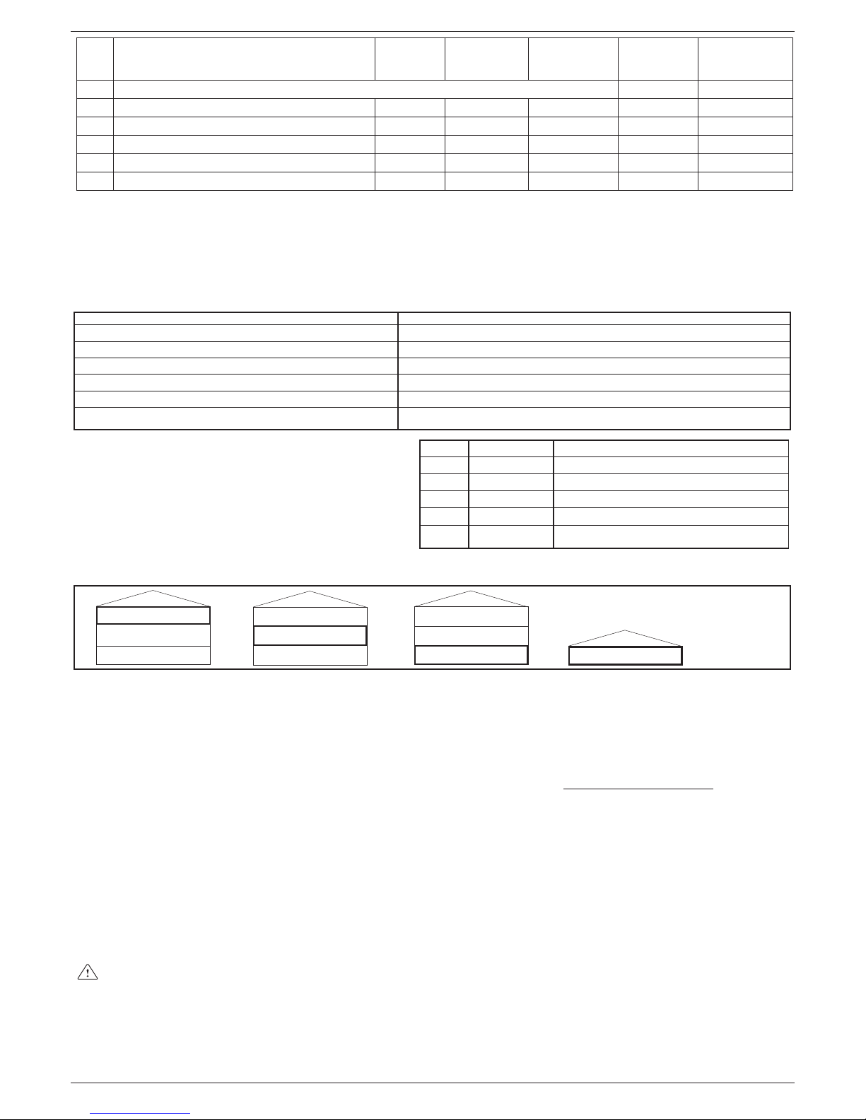
RANGE RATED
This boiler is adjustable to the heat required by the installation; you can in fact set the maximum fl ow rate when the boiler works
on heating. See the “Adjustments” section for calibration.
Once you have set your fl ow rate (PARAMETER 23 for maximum heating), register the value in the special table given here below.
Use this set value as a reference for future controls and adjustments
Output set kW
Date
Fan speed r.p.m.
EN
La caldera EXCLUSIVE GREEN HE B.S.I. cumple con los
requisitos básicos de las siguientes Directivas: Directiva de
gas 2009/142/CEE; Directiva de rendimiento 92/42/CEE;
Directiva Compatibilidad Electromagnética 2004/108/CEE
Directiva Baja Tensión 2006/95/CEE; Norma 677 para calderas de condensación. Por lo tanto, tiene el marcado CE
ES
RANGO DE FUNCIONAMIENTO
Esta caldera se regula al calor requerido por la instalación; de hecho, se puede establecer el caudal máximo cuando la caldera
funciona en calefacción. Ver la sección “Ajustes” para conocer la calibración.
Una vez que se haya establecido el caudal (PARÁMETRO 23 para máxima calefacción), registrar el valor en la siguiente tabla
especial. Utilizar este valor como referencia para controles y ajustes futuros
Salida establecida kW
Fecha
Velocidad del ventilador rpm
ES
EXCLUSIVE BOILER GREEN HE 25 B.S.I. spełnia
podstawowe wymagania następujących dyrektyw
: Urządzenia spalające paliwa gazowe 2009/142/
WE; Sprawność energetyczna kotłów wodnych 92/42/
EWG; Kompatybilność energetyczna 2004/108/EC;
Rozporządzenie dot. niskiego napięcia 2006/95/WE;
Rozporządzenia dot. Kotłów kondensacyjnych EN 677; I w
związku z powyższym posiada znak CE
PL
Centrala EXCLUSIVE BOILER GREEN HE B.S.I. îndeplineşte cerinţele de bază prevăzute de următoarele directive: Directiva pentru gaze 2009/142/CEE; Directiva pentru
randament 92/42/CEE; Directiva de compatibilitate electromagnetică 2004/108/CEE; Directiva de joasă tensiune
2006/95/CEE; Reglementarea 677 pentru centralele cu
condensaţie. Implicit, poartă marcajul CE
RO
EXCLUSIVE BOILER GREEN HE B.S.I. kotel izpolnjuje
bistvene zahteve naslednjih direktiv: Direktiva o plinskih napravah 2009/142/EGS; Direktiva o izkoristkih 92/42/EGS;
Direktiva o elektromagnetni združljivosti 2004/108//ES; Direktiva o nizkonapetostnih napravah 2006/95/EGS; Pravilnik 677 za kondenzacijske kotle. Zato ima oznako CE.
SL
A caldeira EXCLUSIVE BOILER GREEN HE B.S.I. atende
às exigências básicas das seguintes Directivas: Directiva
de gás 2009/142/CEE; Directiva de rendimento 92/42/CEE;
Directiva Compatibilidade Electromagnética 2004/108/
CEE; Directiva Baixa tensão 2006/95/CEE; Regulação 677
para caldeiras de condensação. Desse modo, contém a
marca CE
PT
La CHAUDIÈRE EXCLUSIVE GREEN HE B.S.I. respecte
les conditions requises de base des Directives suivantes :
Directive sur le gaz 2009/142/CEE ; Directive sur le rendement 92/42/CEE ; Directive sur la compatibilité électromagnétique 2004/108/CEE ; Directive basse tension 2006/95/
CEE ; Réglementation 677 pour les chaudières à condensation. Donc, elle est marquée CE.
FR
A EXCLUSIVE BOILER GREEN HE B.S.I. kazán megfe-
lel a következő irányelvek alapvető követelményeinek: Gáz
irányelv 2009/142/EEC; Melegvízkazánokról szóló 92/42/
EGK irányelv; Elektromágneses összeférhetőségről szóló
2004/108/EK irányelv Kisfeszültségű berendezésekről szóló 2006/95/EK irányelv Kondenzációs kazánokra vonatkozó
677 sz. szabályozás. Így rendelkezik CE-jellel
HU

3
EXCLUSIVE BOILER GREEN HE B.S.I.
ZAKRES REGULACJI MOCY
Kocioł ten można dostosować do wymagań systemu centralnego ogrzewania, ponieważ istnieje możliwość obniżenia maksymalnej mocy na c.o. W tym celu należy zapoznać się z rozdziałem Regulacje”
W przypadku zmiany wartości mocy maksymalnej (parametr 23) należy umieścić aktualną wartość w tabeli znajdującej się poniżej.
Jest to bardzo istotne w przypadku wykonywania przeglądów urządzenia.
Nastawiony zakres mocy kotła na c.o. kW
Data
Przy prędkości wentylatora w funkcji c.o. r.p.m.
PL
RANGE RATED
Centrala poate fi reglată la nivelul de căldură necesar în instalaţie; astfel, puteţi seta debitul maxim atunci când centrala
funcţionează pe încălzire. Consultaţi secţiunea „Reglări” pentru calibrare.
După setarea debitului (PARAMETRUL 23 pentru încălzire maximă), înregistraţi valoarea în tabelul special de mai jos.
Utilizaţi această valoare setată ca referinţă pentru controale şi reglări viitoare
Reglare putere termică kW
Data
Turaţie ventilator r.p.m.
RO
RANGE RATED
Ta kotel se regulira glede na potrebe ogrevalnega sistema po toploti; ko kotel deluje v ogrevalnem sistemu, lahko nastavite maksimalno vrednost pretoka. Za umerjanje glejte odsek “Nastavitve”.
Ko ste pretok nastavili (PARAMETER 23 za maksimalno ogrevanje), vrednosti vpišite v posebno tabelo tu spodaj.
Te vrednosti uporabljajte kot referenčne vrednosti med bodočimi pregledi in nastavljanji
Izhodna moč kW
Datum
Hitrost ventilatorja vrt/min
SL
RANGE RATED
Esta caldeira é ajustável ao calor necessário pela instalação; na realidade, é possível ajustar o caudal no máximo quando a caldeira trabalha para aquecer. Consultar a secção “Regulações” para a calibragem.
Uma vez ajustado o seu caudal (PARÂMETRO 23 para aquecimento máximo), registar o valor na tabela especial fornecida aqui
abaixo. Usar esse valor de ajuste como referência para futuros controlos e regulações
Defi nição de potência kW
Data
Velocidade do ventilador r.p.m.
PT
À PUISSANCE AJUSTABLE
La présente chaudière est ajustable à la chaleur requise par l'installation ; vous pouvez en fait régler le débit maximum quand la
chaudière fonctionne en mode chauffage. Voir la section « Réglages » pour le calibrage.
Une fois que vous avez réglé votre débit (PARAMÈTRE 23 pour un chauffage maximum), enregistrez la valeur dans le tableau
spécial indiqué ci-dessous. Utilisez cette valeur de consigne pour référence pour des contrôles et réglages ultérieurs.
Réglage de puissance kW
Date
Vitesse du ventilateur trs/mn
FR
RANGE RATED
Ez a kazán hozzáigazítható a telepítés által megkövetelt hőhöz; beállíthatja a maximális hozamot, amikor a kazán fűtésben dolgozik. Lásd a "Beállítások" c. részt a kalibráláshoz.
Amikor beállította a hozamot (23. PARAMÉTER a maximális fűtéshez), jegyezze fel az értéket az itt alább megadott speciális
táblázatban. Használja ezt a beállított értéket referenciaként a későbbi ellenőrzésekhez és beállításokhoz
Beállított output kW
Dátum
Ventilátor sebesség r.p.m.
HU
4
EXCLUSIVE BOILER GREEN HE B.S.I.
Installer’s - user’s manual 5
Boiler operating elements 160
Hydraulic circuit 162
Electric diagrams 163-167
Circulator residual head 168
The following symbols are used in this manual:
CAUTION = operations requiring special care and ad-
equate preparation
NOT ALLOWED = operations that MUST NOT be per-
formed
EN
Manual de usuario y del instalador 24
Elementos de operación de la caldera 160
Diagramas eléctricos 163-167
Prevalencia residual del circulador 169
En algunas partes del manual se utilizan los símbolos:
ATENCIÓN = para acciones que requieren particular
atención y una adecuada preparación
PROHIBIDO = para acciones que NO DEBEN efectuar-
se nunca
ES
Telepítői-felhasználói kézikönyv 63
A kazán funkcionális alkatrészei 160
Hidraulikus kör 162
Elektromos rajzok 163-167
A keringetőszivattyú maradék emelőnyomása 171
A kézikönyvben az alábbi szimbólumok szerepelnek:
FIGYELEM = megfelelő körültekintést és felkészültséget
igénylő tevékenységek
TILOS = olyan tevékenységek, melyeket szigorúan TI-
LOS végrehajtani
HU
Manual de instalare - utilizare 82
Elementele funcţionale ale centralei 160
Circuit hidraulic 162
Scheme electrice 163-167
Cap rezidual pompă de circulaţie 172
În acest manual sunt utilizate următoarele simboluri:
ATENŢIE = operaţii care necesită o atenţie deosebită şi
o pregătire specifi că
INTERZIS = operaţii care NU TREBUIE efectuate
RO
Priročnik za montažo-uporabo 101
Elementi delovanja kotla 160
Hidravlični sistem 162
Sheme električnih povezav 163-167
Preostala višina črpanja 173
V tem priročniku so uporabljeni naslednji simboli:
POZOR = postopki, ki zahtevajo posebno previdnost in
ustrezno usposobljenost
PREPOVEDANO = postopki, ki se jih NE SME opraviti
SL
Manual do utilizador-instalador 120
Elementos de operação da caldeira 160
Circuito hidráulico 162
Diagramas eléctricos 163-167
Cabeçal residual do circulador 174
Em algumas partes do manual são utilizados os símbolos:
ATENÇÃO = para acções que exigirem particular cuida-
do e preparação adequada
PROIBIDO = para acções que NÃO SE DEVEM absolu-
tamente executar
PT
Manuel de l'installateur - manuel de l'utilisateur 139
Éléments de fonctionnement de la chaudière 160
Circuit hydraulique 162
Schémas électriques 163-167
Hauteur de charge résiduelle 175
Les symboles suivants sont employés dans ce manuel :
PRÉCAUTION = opérations qui exigent un soin particu-
lier et une préparation adéquate.
INTERDICTION = opérations qu'IL NE FAUT PAS réali-
ser.
FR
Instalator / użytkownik instrukcja obsługi 43
Elementy składowe kotła 160
Obiegi hydrauliczne 162
Schematy elektryczne 163-167
Zakres pracy pompy 170
W niektórych częściach instrukcji użyte zostały umowne oznaczenia:
UWAGA = w odniesieniu do czynności wymagających
szczególnej ostrożności oraz odpowiedniego przygotowania
ZABRONIONE = w odniesieniu do czynności, których w
żadnym wypadku NIE MOŻNA wykonywać.
PL
5
EXCLUSIVE BOILER GREEN HE B.S.I.
1- GENERAL SAFETY DEVICES
The boilers produced in our factory are built with care down
to the last component to protect both the user and installer
from eventual accidents. We therefore recommend qualifi ed
personnel that after working on the product they should pay
particular attention to the wiring, especially the bare wires,
that must not be exposed outside the terminal board for any
rason to prevent any contact with the live parts of the wiring.
This instructions manual is integral parts of the product. Make
sure they remain with the boiler, even if it is transferred to
another owner or user or moved to another heating system.
In case of loss or damage, please contact your local Technical
Assistance Service for a new copy.
This boiler may only be installed and serviced by qualifi ed fi t-
ters who satisfy the requirements of local rules. Work must be
done in compliance with regulations in force and subsequent
updates.
The boiler must be serviced at least once a year. This should
be booked in advance with the Technical Assistance Service.
The installer shall instruct the user in the operation of the boil-
er and the safety devices.
This boiler may only be used for what it was expressly built to
do. The manufacturer declines all contractual and non-contractual liability for injury to persons or animals or damage to
property deriving from errors made during installation, adjustment and servicing and from improper use.
This appliance is used to produce hot water and must there-
fore be connected to a heating and/or a domestic hot water
system, according to its performance and power
After removing the packaging, make sure the contents are
undamaged and complete. If this is not the case, contact your
dealer.
We recommend always being careful to control the degree
of wear of the keep-alive anode during ordinary maintenance
jobs.
The safety valve outlet must be connected to a suitable col-
lection and venting system. The manufacturer declines all liability for any damage caused by the safety valve.
The safety and automatic adjustment devices on the appli-
ance must never be modifi ed during its lifetime, except by the
maker or dealer.
If the appliance develops a fault and/or works badly, switch it
off and do not attempt to repair it yourself.
Immediately after installation, inform the user that:
- in the event of leaks, he/she must shut off the water supply
and promptly inform the Technical Assistance Service
- he/she must check from time to time to make sure the
symbol is not lit on the control panel. This symbol means
that the pressure in the water system is incorrect. If necessary, fi ll the system as described in the paragraph “Boiler
functions”
- if the boiler is not planned to be used for a long period, he/
she should call in the Technical Assistance Service to perform the following operations:
- turn off the main boiler and general system switches
- close the gas and water taps on both the heating and domestic hot water circuits
- drain the heating and domestic hot water circuits to prevent
freezing.
Connect the outlet collector to a suitable outlet system (refer
to chapter 6).
Safety measures:
the boiler should not be used by children or unassisted disa-
bled people
electrical devices or equipment, such as switches, applianc-
es, etc., should not be used if there is a smell of gas or fumes.
If there is a gas leak, open all the doors and windows to ventilate the area, turn off the general gas tap and immediately call
the Technical Assistance Service
do not touch the boiler barefoot or if parts of your body are
wet or damp
press the button until “- -” is shown on the display and dis-
connect the electricity supply by turning off the two-position
system switch, before cleaning
it is forbidden to modify the safety or adjustment devices with-
out the manufacturer’s permission and relative instructions
do not pull, detach or twist the wires from the boiler even if
they are not connected to the power supply
do not block or reduce the size of the ventilation openings in
the room
do not leave infl ammable containers or substances in the
room
keep packaging out of reach of children
only use appliance for purposes it is devoted to
do not lean any object on the boiler
do not tamper with sealed elements
it is forbidden to block the condensate outlet.
2- BOILER INSTALLATION
Boiler must only be installed by qualifi ed personnel in compliance
with current legislation. Boiler is available in the following models:
Model Type Category Power
B.S.I. Combined C 25 kW - 35 kW
Exclusive Boiler Green HE B.S.I. is a C-type condensation wallmounted boiler for heating and producing domestic hot water,
supplied with a 60 litres inox water tank. Class C appliances can
be installed in any kind of room as long as the fumes discharge
and the comburent air intake are taken outside the room. The following types of fumes outlet are available for this kind of boiler:
B23P; B53P; C13,C13x; C23; C33,C33x; C43,C43x; C53,C53x;
C63,C63x; C83,C83x; C93,C93x. Installation must comply with local standards and regulations in force.
For proper installation, we remind you that:
- the boiler must not be installed over a kitchen or any other cooking equipment
- it is forbidden to leave infl ammable substances in the room
- suitably insulate heat-sensitive walls (e.g.: in wood)
- minimum spaces are to be left in order to allow maintenance
operations: at least 2,5 cm every side and 20 cm under the boiler.
Keep the distance of 370 mm from the bottom of the boiler
to the furniture casing: there must be suffi cient space for
dismantling operations if the magnesium anode has to be
cleaned.
Support plate and integrated pre-installation template are provided
for with the boiler (fi g. 2).
Mounting instructions:
- fi x the boiler support plate (F) with the template (G) to the wall
and use a plumb to check that it is perfectly horizontal
- trace out 4 holes (ø 6 mm) for fi xing the boiler support plate (F)
and 2 holes (ø 4 mm) for fi xing the preinstallation template (G)
- make sure all the measurements are correct, then drill holes in
the wall using a drill and point with the diameter given previously
- fi x the plate to the wall by the supplied anchor screws
- make hydraulic connections.
3- HYDRAULIC CONNECTIONS
Position and dimensions of hydraulic connections are specifi ed in
fi gure 2:
A - CH return 3/4”
B - CH delivery 3/4”
C - Gas connection 3/4”
D - DHW outlet 1/2”
E - DHW inlet 1/2”
F - Support plate
G - Pre-installation template
If water hardness exceeds 28°Fr, it is recommended to use water
softeners, to prevent any limestone deposit in boiler due to excessively hard water.
EN
ENGLISH
6
EXCLUSIVE BOILER GREEN HE B.S.I.
4- CLEANING THE SYSTEM AND CHARACTERISTICS
OF HEATING CIRCUI
T WATER
After installing a new system or replacing a boiler, clean the heating system.
To ensure the product works correctly, after cleaning, additivating
and/or chemically treating the system (e.g.: anti-freeze, fi lm-form-
ers, etc.), make sure the characteristics of the water satisfy the
parameters indicated in the table.
Parameters um Water in heating
circuit
Inlet water
PH 7 ÷ 8 Hardness ° F - 15 ÷20
Appearance - limpid
5- INSTALLING THE EXTERNAL PROBE
Install the probe (fi g. 4) in an area of smooth wall; for brick walls
or other irregular surfaces, prepare a smooth contact area if at all
possible.
Remove the upper plastic cover by turning it anti-clockwise.
Identify the wall fi xing point and drill a hole for the 5x25 expansion
grip. Insert the expansion grip into the hole. Remove the card from
its housing. Fix the housing to the wall using the supplied screw.
Attach the bracket and tighten the screw. Loosen the cable grommet screw, push in the probe connection cable and connect it to the
electrical terminal. Remember to fi rmly secure the cable grommet
to prevent humidity from entering. Put the card back into its housing. Close the upper plastic cover by turning it clockwise. Firmly
secure the cable grommet.
Installing and connecting up the external sensor
The sensor must be installed on an external wall of the building
you want to heat, while taking care to comply with the instructions
below:
- It must be fi tted on the facade most often exposed to wind, on a
wall facing NORTH or NORTH-WEST, and taking care to avoid
direct sunlight.
- It must be fi tted about 2/3 up the height of the façade.
- It must not be near any doors, windows, outlets for air ducts, or
near chimneys or other heat sources.
The electrical connection to the external sensor must be formed
using a two-pole cable (not supplied), with a cross-section of 0,5
to 1 mm2 and a maximum length of 30 metres. It is not necessary
to worry about the polarity of the cable for the connection to the
external sensor. Do not form joints in this cable. If a joint has to be
made it must be watertight and adequately protected.
Any conduiting used for the connection cable must be sepa-
rate from the conduits used for the power cables (230 Vac).
6- CONDENSATE COLLECTION
The outlet collector (A, fi g. 5) collects: the condensate water, any
evacuation water from the safety valve and the system outlet water.
The collector must be connected, by means of a rubber pipe,
to a suitable collection and evacuation system in the storm
water outlet and in compliance with current regulations.
The external diameter of the collector is 20 mm: we therefore
suggest using an Ø18-19 mm pipe, to be closed with a suitable clamp (not supplied).
The manufacturer is not responsible for any damage caused
by the lack of a collection system.
The outlet connection line must have a guaranteed seal.
The manufacturer of the boiler is not responsible for any
fl ooding caused by interventions of the safety valve.
7- GAS CONNECTION
Before connecting appliance to gas pipe network, check the following:
- regulations in force are met
- gas type used is the same as set for appliance operation
- pipes are clean.
After installation make sure that all the joints have been made
airtight conforming to standard installation practices.
Gas must be piped externally. If the pipe goes through a wall it must
go through the central opening in the lower part of the template. It
is recommended to install an appropriately sized fi lter on the gas
line in case gas from the mains contains some small solid particles.
8- ELECTRIC CONNECTION
To access the electrical connections, proceed as follows:
- loosen the fi xing screws (A) and remove the shell (fi g. 3)
- lift up the panel and turn it forwards
- open the terminal board covers making them slide in the direc-
tion of the arrows (fi g. 6: B high voltage connections 230 V, C low
voltage connections).
Connect the appliance to the mains electricity supply with a switch
featuring a distance of at least 3,5 mm (EN 60335-1, category III)
between each wire. The appliance uses alternating current at 230
Volt/50 Hz, has a power input of 66W (25 B.S.I.) - 116W (35 B.S.I.)
and complies with EN 60335-1. The appliance must be connected
to an effi cient earth circuit, according to current legislation and by-
laws.
Live and neutral (L-N) connections should also be respected.
The boiler can operate with phase-neutral or phase-phase power
supply. For fl oating power supply, without an earth-bonded conduc-
tor, it is necessary to use an insulation transformer with secondary
anchored to ground.
The earth conductor must be a couple of cm longer than the
others.
Gas and/or water pipes may not be used to earth electrical
equipment.
The installer is responsible for making sure that the appliance
has an adequate earthing system; the manufacturer shall not
be held liable for eventual damages caused by incorrect usage or failing to earth the boiler.
Use the supplied power cable to connect the boiler to the mains
power supply.
Connect the ambient thermostat and/or time clock as shown in the
electrical diagram.
When replacing the power cable, use a HAR H05V2V2-F cable,
3 x 0,75 mm2, Ø max. external 7 mm.
9- FILLING THE SYSTEMS, ELIMINATING THE
AIR AND EMPTYING THE SYSTEMS
The systems can be fi lled up once the water mains have been con-
nected up.
This must be done while the installation is cold by:
DHW system (fi g. 7)
- open the cold water stopcock (H) to fi ll up the water tank
- open the hot water to check the water tank fi lled up and wait until
the water discharge
Heating system (fi g. 7)
- making sure that the drain valve (B) is closed
- giving two or three turns to the cap of the automatic air vent valve
(C) to open it
- opening the fi lling stopcock (I) until the pressure measured by
the hydrometer (D) is about 1,5 bar (blue zone)
- open the manual vent valve (E) and close it again once the system has been vented; if necessary, repeat this operation until no
more air leaves the valve (E)
- close the fi lling stopcock (I)
- each time the electricity supply to the boiler is switched on, an
automatic vent cycle lasting about 2 minutes starts, and the display reads “SF”, and the “functions selectors”
light up in sequence. Press the button to interrupt the automatic venting cycle.
NOTE: air extraction from the boiler takes place automatically,
through two automatic bleeding valves, C and F.
NOTE: the boiler is also equipped with a semi-automatic fi lling sys-
tem. The fi rst system-fi lling operation must be carried out by open-
ing tap I with the boiler turned off.
CH system emptying (fi g. 7)
Before starting to empty it, remove the electrical feeder by positioning the general switch for the system on “off”.

7
EXCLUSIVE BOILER GREEN HE B.S.I.
- Close the interception devices for the thermal system
- Open the automatic air vent valve (C)
- Unscrew the drain valve (B) by hand, keeping the elbow on the
hose in position to prevent it coming out of its seating
- The water from the system is discharged through the outlet col-
lector (A)
- Emptying out the lowest parts of the system.
DHW system emptying (fi g. 7)
The hot water system must be emptied every time there is risk of
freezing by:
- turning off the stopcock at the mains
- unscrew the cap on the hose adapter (G)
- connect a plastic hose to the hose adapter of the storage boiler
drain valve (G)
- open the valve drain device
- turning on all the hot and cold taps
- emptying out the lowest parts of the system.
ATTENTION
The collector must be connected, by means of a rubber pipe, to a
suitable collection and evacuation system in the storm water outlet
and in compliance with current regulations. The external diameter
of the collector is 20 mm: we therefore suggest using an Ø18-19
mm pipe, to be closed with a suitable clamp (not supplied). The
manufacturer is not responsible for any damage caused by the lack
of a collection system.
Suggestions to correctly eliminate air from the heating system
and boiler (Fig. 8)
We recommend carrying out the sequence of operations given below during fi rst installation or with extraordinary maintenance work:
1. Using a CH11 spanner open the manual air vent valve located
above the air box; the tube supplied with the boiler must be connected to the valve to let out the water into an outside container.
2. Open the manual system fi lling stopcock on the water group,
wait until the water starts coming out of the valve;
3. Switch on the boiler leaving the gas cock closed;
4. Use the room thermostat or the remote control panel to activate
request for heat so that the three-way will turn to heating;
5. Activate request for hot water as follows:
instant boilers: turn on a tap for 30” every minute so that the
three-way cycles from heating to domestic hot water and vice
versa about ten times (here the boiler will go into alarm as it
lacks gas and has to be reset every time this happens).
Heating only boilers connected to an external water tank:
use the water tank thermostat;
6. Continue the sequence until water only comes out of the manual
air vent valve and the fl ow of air has fi nished; close the manual
air vent valve at this point;
7. Make sure the system is at the correct pressure (1 bar is ideal);
8. Close the manual system fi lling stopcock on the water group;
9. Open the gas cock and ignite the boiler.
10- FUMES EXHAUSTION AND BURNING AIR
SUCTION
EXHAUSTION CONFIGURATIONS (fi g. 9)
Boiler is homologated for the following exhaustion confi gurations:
B23P-B53P Suction in room and discharge outside
C13-C13x Concentric wall exhaustion. Pipes can separately start
from boiler, but outlets must be concentric or close enough to be
subject to similar wind conditions (within 50 cm).
C23-C23x Concentric exhaustion in common chimney (suction and
exhaustion in the same chimney).
C33-C33x Concentric roof exhaustion. Outlets like C13.
C43-C43x Exhaustion and suction in common separate chimneys,
but subject to similar wind conditions.
C53-C53x Wall or roof separate exhaustion and suction in different
pressure areas. Exhaustion and suction must never be located on
opposite walls.
C63-C63x Exhaustion and suction with separately certifi ed and
sold pipes (1856/1).
C83-C83x Single or common chimney exhaustion and wall suction.
C93-C93x Discharge on roof (similar to C33) and air suction from a
single existing smoke pipe
Refer to regulations in force for exhaustion of combustion products.
Boiler is provided for without fume exhaustion/air suction kit, since
forced draught sealed chamber accessories can be used, as they
better adapt to installation characteristics. For fume extraction and
burning air restoration in boiler, use original pipes or other EC-certifi ed pipes with equivalent characteristics; check connection is cor-
rect as shown on instructions fume accessories provided for with.
More appliances can be connected to a single chimney, provided
that all appliances are sealed chamber type.
“FORCED OPEN” INSTALLATION
(TYPE B23P-B53P, intake inside and outlet outside)
Fumes outlet duct ø 80 mm - fi g. 13
The fumes outlet duct can be aimed in the most suitable direction
for installation needs.
To install follow the instructions supplied with the kit.
In this confi guration, the boiler is connected to the ø 80 mm fumes
outlet duct by means of a ø 60-80 mm adaptor.
In this case, the combustion supporting air is taken from the
room in which the boiler is installed, which must be a suitable
and ventilated technical room.
Non-insulated fumes outlet ducts are potential sources of
danger.
Provision must be made for a 1% slope of the fumes outlet
duct towards the boiler.
max length fumes
outlet duct ø 80 (m)
pressure drop
for each bend (m)
45° 90°
25 B.S.I. 50
1 1,5
35 B.S.I. 60
INSTALLATION “SEALED” (TYPE C)
Boiler is a C-type appliance (sealed chamber) and must be safely
connected to fume exhaustion duct and burning air suction duct,
both getting outside; appliance cannot operate without these ducts.
Concentric outlets (ø 60-100) - Fig. 11
Concentric ducts may be placed in the most suitable direction for
installation requirements but special care must be taken as regards
the external temperature and the length of the duct.
Horizontal
max. linear length
concentric duct ø 60-100 (m)
pressure drop
for each bend (m)
7,85
45° 90°
1,3 1,6
Vertical
max. linear length
concentric duct ø 60-100 (m)
pressure drop
for each bend (m)
8,85
45° 90°
1,3 1,6
Rectilinear length means without bends, outlet ends and con-
nections.
The fumes outlet duct must slope by 1% towards the conden-
sate collector.
Uninsulated fumes outlets are potential hazards.
The boiler automatically adapts ventilation according to the
type of installation and the length of the duct.
Do not obstruct or narrow the comburent air inlet duct in any way.
To install follow the instructions supplied with the kit.
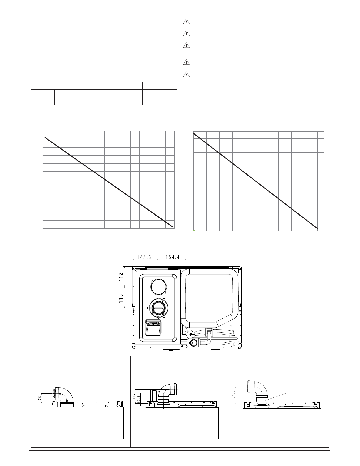
Concentric outlets (ø 80-125 mm)
For this installation it is necessary to install the suitable adaptor kit.
Ducts may be placed in the most suitable direction for installation requirements. For the installation process, follow the instructions supplied with the kit for the specifi c accessory for condensation boilers.
max. linear length
concentric duct ø 80-125 (m)
pressure drop
for each bend (m)
14,85
45° 90°
1 1,5
8
EXCLUSIVE BOILER GREEN HE B.S.I.
CONCENTRIC DUCT
FOR FUMES OUTLET/AIR INTAKE
SPLIT DUCTS
FOR FUMES OUTLET/AIR INTAKE
FUMES DUCT FOR INTAKE
IN ENVIRONMENTS
adaptor
Ø 60-80
LENGTH OF THE INTAKE DUCT (m)
EXHAUSTION LENGHT (m)
10
11
12 13
0
5
10
15
20
25
30
35
40
45
50
55
60
65
70
0 5 10 15 20 25 30 35 40 45 50 55 60 65 70 75 80 85 90 95 100
0
5
10
15
20
25
30
35
40
45
50
55
60
0 5 10 15 20 25 30 35 40 45 50 55 60 65 70 75
EXCLUSIVE BOILER GREEN HE 25 B.S.I.
EXCLUSIVE BOILER GREEN HE 35 B.S.I.
LENGTH OF THE INTAKE DUCT (m)
EXHAUSTION LENGHT (m)
Twin outlets (ø 80) - fi g. 12
The split duct can be aimed in the most suitable direction for installation needs. The combustion-supporting air intake duct must be
connected to the entrance after having removed the closing cap,
attached with three screws, and having attached a suitable adaptor.
The fumes outlet duct must be connected to the fumes outlet after
having installed a suitable adaptor.
For the installation process, follow the instructions supplied with
the kit for the specifi c accessory for condensation boilers.
max. linear length
twin duct ø 80 (m)
pressure drop
for each bend (m)
45° 90°
25 B.S.I. 32+32
1 1,5
35 B.S.I. 40+40
Rectilinear length means without bends, outlet ends and
connections.
The fumes outlet duct must slope by 1% towards the conden-
sate collector.
The boiler automatically adapts ventilation according to the
type of installation and the length of the duct. Do not obstruct
or narrow the comburent air inlet duct in any way.
For an indication of the maximum lengths of every single
pipe, refer to the graphs.
Using longer ducts causes a loss in the power of the boiler.
9
EXCLUSIVE BOILER GREEN HE B.S.I.
DESCRIPTION
EXCLUSIVE BOILER GREEN HE
25 B.S.I.
EXCLUSIVE BOILER GREEN HE
35 B.S.I.
Heating Heat input kW 25,00 34,60
kcal/h 21.500 29.756
Maximum heat output (80/60°) kW 24,38 33,74
kcal/h 20.963 29.012
Maximum heat output (50/30°) kW 26,20 36,50
kcal/h 22.532 31.393
Minimum heat input (G20/G31) kW 2,50/4,50 3,50/6,20
kcal/h 2.150/3.870 3.010/5.332
Minimum heat output (80°/60°) (G20/G31) kW 2,49/4,47 3,41/6,04
kcal/h 2.144/3.847 2.929/5.193
Minimum heat output (50°/30°) (G20/G31) kW 2,69/4,82 3,71/6,57
kcal/h 2.309/4.145 3.188/5.647
Nominal Range Rated heat output (Qn) kW 25,00 34,60
kcal/h 21.500 29.756
Minimum Range Rated heat output (Qm) (G20/G31) kW 2,50/4,50 3,50/6,20
kcal/h 2.150/3.870 3.010/5.332
DHW Heat input kW 25,00 34,60
kcal/h 21.500 29.756
Maximum heat output (*) kW 25,00 34,60
kcal/h 21.500 29.756
Minimum heat input (G20/G31) kW 2,50/4,50 3,50/6,20
kcal/h 2.150/3.870 3.010/5.332
Minimum heat output (*) (G20/G31) kW 2,50/4,50 3,50/6,20
kcal/h 2.150/3.870 3.010/5.332
(*) average value of various DHW operating conditions
Useful effi ciency (Pn max - Pn min) % 97,5 - 99,7 (G31= 99,4) 97,5 - 97,3 (G31= 97,4)
Effi ciency 30% (47° return) % 102,8 103,1
Combustion performance % 97,8 97,7
Useful effi ciency Pn max - Pn min (50°/30°) % 104,8 - 107,4 (G31= 107,1) 105,5 - 105,9 (G31= 105,9)
Useful effi ciency 30% (30° return) % 109,4 108
Average Range Rated effi ciency Pn (80°/60°) % 98,1 97,6
Average Range Rated effi ciency Pn (50°/30°) % 105,2 106,1
Electric power W
66 116
Category II2H3P II2H3P
Country of destination -Power supply voltage V - Hz 230-50 230-50
Degree of Protection IP X5D X5D
Pressure drops on fl ue with burner on % 2,16 2,30
Pressure drops on fl ue with burner off % 0,10 0,08
Heating operation
Pressure - maximum temperature bar - °C 3 - 90 3 - 90
Minimum pressure for standard operation bar 0,25 - 0,45 0,25 - 0,45
Selection fi eld of heating water temperature °C 20 - 80 20 - 80
Pump: maximum head available mbar 127 320
for system capacity l/h 800 1.000
Membrane expansion tank l 10 10
Expansion tank pre-charge bar 1 1
DHW operation
Maximum pressure bar 8 8
Minimum pressure bar - 0,15
Hot water quantity with ∆t 25°C l/min 14,3 19,8
with ∆t 30°C l/min 11,9 16,5
with ∆t 35°C l/min 10,2 14,2
DHW minimum output l/min - 2
Selection fi eld of DHW temperature °C 35 - 60 35 - 60
Flow regulator l/min 15 15
Gas pressure
Methane gas nominal pressure (G20) mbar 20 20
LPG liquid gas nominal pressure (G31) mbar 37 37
Hydraulic connections
Heating input - output Ø 3/4” 3/4”
DHW input-output Ø 1/2” 1/2”
Gas input Ø 3/4” 3/4”

10
EXCLUSIVE BOILER GREEN HE B.S.I.
DESCRIPTION
EXCLUSIVE BOILER GREEN HE
25 B.S.I.
EXCLUSIVE BOILER GREEN HE
35 B.S.I.
Boiler dimensions
Height mm 940 940
Width mm 600 600
Depth of housing mm 450 450
Boiler weight kg 65 72
Flow rate (G20)
Air capacity Nm3/h 31,135 43,090
Flue gas capacity Nm3/h 33,642 46,561
Mass fl ow of fl ue gas (max-min) gr/s 11,282-1,070 15,614 - 1,498
Flow rate (G31)
Air capacity Nm3/h 31,752 43,945
Flue gas capacity Nm3/h 32,721 45,286
Mass fl ow of fl ue gas (max-min) gr/s 11,046-1,988 15,288 - 2,740
Fan performance
Residual head of boiler without pipes Pa 98 199
Residual head of concentric pipes 0,85 m Pa 40 60
Residual head of separate pipes 0,5 m Pa 90 195
Concentric fl ue gas discharge pipes
Diameter mm 60-100 60-100
Maximum length m 7,85 7,85
Drop due to insertion of a 45°/90° bend m 1,3/1,6 1,3/1,6
Hole in wall (diameter) mm 105 105
Concentric fl ue gas discharge pipes
Diameter mm 80-125 80-125
Maximum length m 14,85 14,85
Drop due to insertion of a 45°/90° bend m 1/1,5 1/1,5
Hole in wall (diameter) mm 130 130
Separate fl ue gas discharge pipes
Diameter mm 80 80
Maximum length m 32+32 40+40
Losses for a 45°/90° bend m
1/1,5 1/1,5
Installation B23P–B53P
Diameter mm 80 80
Maximum length of drainage pipe m 50 60
NOx class 55
Emission values at max. and min. rate of gas G20*
Maximum - Minimum CO s.a. less than ppm 180 - 5 180 - 10
CO
2
% 9 - 9,5 9 - 9,5
NOx s.a. lower than ppm 45 - 10 35 - 15
Flue gas temperature °C 76 - 59 74 - 62
* Check performed with concentric pipe ø 60-100, length 0,85m - water temperature 80-60°C
EXCLUSIVE BOILER GREEN HE
25 B.S.I.
EXCLUSIVE BOILER GREEN HE
35 B.S.I.
Water tank type Inox Inox
Water tank disposition vertical vertical
Exchanger disposition vertical vertical
DHW contents l 60 60
Coil contents l 3,87 3,87
Exchange surface m
2
0,707 0,707
Selection fi eld of DHW temperature °C 35 - 60 35 - 60
Flow regulator l/min 15 15
Hot water quantity drawn in 10’ with Δt 30 °C l 202 202
Water tank maximum pressure bar 8 8
11
EXCLUSIVE BOILER GREEN HE B.S.I.
DESCRIPTION Methane gas (G20) Propane (G31)
Lower Wobbe index (at 15°C-1013 mbar) MJ/m3S 45,67 70,69
Net Calorifi c Value
MJ/m
3
S
MJ/KgS
34,02
-
88
46,34
Supply nominal pressure
mbar
mm W.C.
20
203,9
37
377,3
Supply minimum pressure
mbar
mm W.C.
10
102
-
Exclusive Boiler Green HE 25 B.S.I.
Burner: diameter of nozzles - lenght mm - mm 63 - 130 63 - 130
Diaphragm: number of holes - diameter of holes n° - mm 2 - 3,65 2 - 2,95
Heating maximum gas capacity Sm
3
/h 2,64
kg/h 1,94
DHW maximum gas capacity Sm3/h 2,64
kg/h 1,94
Heating minimum gas capacity Sm
3
/h 0,26
kg/h 0,35
DHW minimum gas capacity Sm
3
/h 0,26
kg/h 0,35
Numbers of fan revolutions at slow start revs/min 3.700 3.700
Maximum number of fan revolutions (CH) revs/min 6.000 6.000
Maximum number of fan revolutions (DHW) revs/min 6.000 6.000
Minimum number of fan revolutions (CH) revs/min 1.200 1.900
Minimum number of fan revolutions (DHW) revs/min 1.200 1.900
Exclusive Boiler Green HE 35 B.S.I.
Burner: diameter of nozzles - lenght mm - mm 63 - 140 63 - 140
Diaphragm: number of holes - diameter of holes n° - mm 2 - 3,8 2 - 3,05
Heating maximum gas capacity Sm
3
/h 3,66
kg/h 2,69
DHW maximum gas capacity Sm3/h 3,66
kg/h 2,69
Heating minimum gas capacity Sm
3
/h 0,37
kg/h 0,48
DHW minimum gas capacity Sm
3
/h 0,37
kg/h 0,48
Numbers of fan revolutions at slow start revs/min 3.300 3.300
Maximum number of fan revolutions (CH) revs/min 6.000 5.900
Maximum number of fan revolutions (DHW) revs/min 6.000 5.900
Minimum number of fan revolutions (CH) revs/min 1.200 1.900
Minimum number of fan revolutions (DHW) revs/min 1.200 1.900

12
EXCLUSIVE BOILER GREEN HE B.S.I.
Description of commands
Heating water temperature selector: sets the heating water
temperature.
Domestic hot water temperature selector: sets the domestic
hot water temperature storaged in the water tank.
Setting parameters selector: using in calibration and program-
mation phase.
Function key:
- ON the boiler is electrically powered and waiting for operating requests (
- )
- OFF the boiler is electrically powered but will not respond to
operating requests
- RESET resets the boiler following a fault
Operating mode button:
button allows to choose the
desired operating mode: (winter) or (summer).
Info button: shows a sequence of information concerning the
operating status of the machine.
Filling button: pushing it, the boiler automatically fi lls the system
until the pressure reaches 1 to 1.5 bar.
Description of display symbols
15
14
graduated heating water temperature scale with
heating function symbol
graduated domestic hot water temperature scale with
domestic hot water function symbol
domestic hot water function symbol
fault symbol
reset symbol
pressure value
external sensor connection
heating/domestic hot water temperature
or
fault symbol (e.g. 10 - no fl ame)
function selector (turned to the chosen operating mode:
winter or summer)
burner operating symbol
anti-freeze function active symbol
system fi lling function symbol
fi ll symbol
Domestic
hot water
temperature
selector
Operating
mode button
ON-OFF-RESET
function selector
Filling
button
Heating
water circuit
temperature
selector
INFO
button
Setting
parameters
selector
12 - START-UP AND OPERATION
The boiler produces heating and domestic hot water.
The control panel (fi g. 14) contains the main boiler control and ma-
nagement functions.

13
EXCLUSIVE BOILER GREEN HE B.S.I.
Switching on
Switch on the boiler as follows:
- access the gas tap through the slots in the cover located in the
lower part of the boiler
- open the gas tap by turning it anti-clockwise (fi g. 16)
- power the boiler.
Each time the power supply is switched on the boiler carries out
an automatic venting cycle that lasts about 2 minutes. The display
reads “SF” (fi g. 17) and the “function selectors”
light up in
sequence. Press the
button to interrupt the automatic
venting cycle.
If the check is concluded correctly, once the automatic venting cycle
has been completed the boiler is ready to work.
The boiler turns on in the status it was in before it was switched
off: if the boiler was in the winter mode when it was switched
off, it will turn on again in the winter mode. If it was in the OFF
mode, the display will show two segments in the central area
(fi g. 18). Press the button to enable operation.
Choose the desired operating mode by pressing
button,
until the symbol moves to:
WINTER
SUMMER
WINTER function (fi g. 19)
With the selector in this position, the boiler provides hot water for
the heating and provides water to the water tank to allow domestic
hot water preparation. Function S.A.R.A is enabled in this position
(see chapter “Boiler functions”).
SUMMER function (fi g. 20)
With the selector in this position, the boiler provides water to the
water tank with a temperature stabiliser to allow domestic hot water
preparation.
16
17
18
19
Adjusting heating water temperature
Turning the selector A (fi g. 21), after having positioned the selector
mode on winter
, it is possible to regulate the heating water
temperature.
Turn clockwise to increase the temperature and anticlockwise to
decrease. The bar segments light up (every 5°C) as the temperature
is increased. The selected temperature value appears on the display.
Adjusting heating water temperature with an external sensor
connected
When an external probe is connected, the value of the delivery
temperature is automatically chosen by the system which rapidly
adjusts ambient temperature to the changes in external temperature.
Just the central segment of the bar is illuminated (fi g. 22).
To increase or decrease the temperature with respect to the value
automatically calculated by the electronic board, turn the heating
water selector clockwise to increase and anticlockwise to decrease.
The bar segments light up (at every comfort level), correction tolerance lies between - 5 and + 5 comfort levels (fi g. 22). When choosing
the level of comfort, the digit area of the display shows the required
level of comfort while the bar shows the matching segment (fi g. 23).
Adjusting domestic hot water temperature
To adjust domestic hot water temperature storaged in the water
tank, turn switch B (fi g. 24) clockwise to increase and anticlock-
wise to decrease. The bar segments light up (every 3°C) as the
temperature is increased.
The selected temperature value appears on the display.
When choosing the temperature, both for heating and domestic
hot water, the display shows the value being selected
. . About 4
seconds after the selection has been made, the modifi cation is
memorised and the display returns to the delivery temperature
read by the probe
. .
20
A
21
22
23
°C
+ 4/5
+ 3
+ 2
+ 1
0
- 1
- 2
- 3
- 4/5
open
position

14
EXCLUSIVE BOILER GREEN HE B.S.I.
Working the boiler
Adjust the ambient thermostat to the required temperature (approx.
20 °C). If there is a demand for heating water, the boiler starts
and the symbol is shown on the display (fi g. 25). The boiler
will remain working until the set temperatures are reached, after
which it will go on stand-by. In the event of ignition or operating
faults, the boiler will perform a “safety stop”.
The fl ame symbol
will go out and the fault code and will
be displayed (fi g. 26). For a description of faults and how to reset
them, consult chapter “Troubleshooting”.
Switching off
Switching off for short periods
For brief absences press the
button to switch off the boiler. The
display will show two segments in the central area (fi g. 27). When
the boiler remains powered with the gas tap open, it is protected
by the following systems:
- anti-freeze: when the temperature of the water in the boiler
falls below safety values, the circulator and the burner work
at minimum power to increase the water temperature to a safe
value (35 °C). The symbol lights up on the display (fi g. 27).
- circulator anti-block: one operating cycle is performed every
24 hours.
Switching off for long periods
For prolonged absences press the button to switch off the boiler
(fi g. 27). The display will show two segments in the central area.
Turn the main switch to “off”.
Turn off the gas tap under the boiler by turning it clockwise (fi g. 28).
In this case, the anti-freeze and anti-block systems are disa-
bled.
Empty the water circuit or suitably protect it with a good make
of anti-freeze. Drain the domestic hot water circuit.
24
B
tap
closed
27
28
Boiler functions
Semi-automatic fi lling
The boiler features a semi-automatic fi lling device which turns on
by pressing the button when the corresponding symbol is
shown on the display (fi g. 29).
If this condition occurs it means that the system is incorrectly pressurised though the boiler will continue to work regularly. Press the
circuit fi lling button
to start-up the fi lling sequence.
Press the circuit fi lling button a second time to interrupt the
fi lling sequence. During fi lling, the drops of the circuit fi lling symbol
and the growing pressure value appear on the display in a
cascade sequence (fi g. 30).
After fi lling, the symbol is displayed for a few moments and
then turns off.
Note
During fi lling, the boiler does not perform other functions. For
example, if there is a request for domestic hot water, the boiler is
unable to provide it until fi lling has fi nished.
Note
If circuit pressure reaches 0.6 bar, the pressure value fl ashes
on the display (fi g. 31a); if it falls below a minimum safety value
(0.3 bar), fault code 41 appears on the display (fi g. 31b) for a
certain time, following which, if the fault persists, fault code 40
is displayed (see chapter on “Troubleshooting”).
In the event of fault 40, press
to reset and then to start fi lling
the circuit. After correcting fault 40, the boiler runs an automatic
vent cycle lasting about 2 minutes; the display reads “SF” (fi g.
32) and the “function selectors” light up in sequence. Press
the
button to interrupt the automatic venting
cycle.
If
you have to fi ll the system several times, contact the Technical
Service Centre to check whether the heating circuit is watertight
(see if there are any leaks).
29
30
25
26
31a
31b
32

15
EXCLUSIVE BOILER GREEN HE B.S.I.
Information
Press
, the display turns off and just the word InFO appears (fi g.
33). Press the button to view operating information. Press the
button again to move on to the next piece of information. If the
button is not pressed, the system automatically exits the function.
Info list:
Info 0 shows the word InFO (fi g. 33)
Info 1 only with the external probe connected, displays external
temperature (e.g. 12 °C) (fi g. 34).
The values shown on the display range between - 30 °C
and 35 °C.
Beyond these values the display shows “- -”
Info 2 shows circuit pressure (fi g. 35)
37
38
36
35
34
33
Info 3 shows the set heating temperature (fi g. 36)
Info 4 shows the set domestic hot water temperature (fi g. 37)
Info 5 displays the set heating temperature, in reference to the
second circuit, only if it is connected.
S.A.R.A. function - fi g. 38
If the “winter” mode is selected, the S.A.R.A. (Automatic Ambient
Adjustment System) function can be activated.
Turning the heating water temperature selector to a temperature
ranging between 55 and 65 °C the S.A.R.A. self-adjustment system activates: depending on the temperature set on the ambient
thermostat and the time taken to reach it, the boiler automatically
adjusts the heating water temperature to reduce operating times,
thereby increasing operating comfort and energy saving.
It is possible to display information, which may be useful for the
Technical Assistance Centre, by pressing the button
for 10 sec-
onds: the code “INF2” appears on the display.
INF2
Step Description Display Display
2 digits 4 digits
1 Input probe temperature xx 01 ° C
2 Return probe temperature xx 02 ° C
3 First water tank probe temperature (*) xx 03 ° C
4 Not used in this model xx Cond ° C
5 Fumes probe temperature xx (**) 05
6 Second heating system probe temperature xx 06 ° C
7 Not used in this model xx 07
8 Ventilator speed /100 xx FAN
9 Not used in this model xx 09
10 Not used in this model xx 10
11 Exchanger cleaning counter status bH xxxx
12-19 Historic alarm codes xx HIS0-HIS7
INF2 list
Note (*): if the water tank probe is faulty or disconnected, in the place of the value “- -” is displayed.
(**): if the display also shows the dot (.), the temperature of the fumes probe is 100+displayed value
16
EXCLUSIVE BOILER GREEN HE B.S.I.
Troubleshooting
When a fault appears on the display, the fl ame symbol goes
out, a fl ashing code is shown and the two symbols and
appear either together or separately.
For a description of the faults, consult the following table.
(D) Permanent
(T) Temporary. In this operating status the boiler attempts to eliminate the fault on its own
(°) See NOTE in the next page.
(*) If these two errors occur, check the pressure indicated on the water gauge. If the pressure is insuffi cient (< 0,4 bar, red area), proceed with the fi lling
operations described in the chapter “Filling and emptying the systems”.
If the system’s pressure is suffi cient (> 0,6 bar, blue area) the malfunction is caused by a lack of water circulation. Contact the Technical Assistance.
(-) Call the technical assistance service
FAULT Alarm Symbol Symbol
ID
FLAME FAILURE BLOCK (D) 10 YES NO
PARASITE FLAME (T) 11 NO YES
RE-ATTEMPT IN PROGRESS (T) 12 NO NO
MINIMUM GAS INPUT PRESSURE (T) 13 NO YES
MINIMUM GAS INPUT PRESSURE (D) 14 YES NO
FLAME PRESENT IN STAND-BY FOR NO REASON (D) 15 YES YES
LIMIT THERMOSTAT (D) 20 YES NO
SHORT CIRCUIT FUMES PROBE (D) 21 YES YES
MAXIMUM TEMPERATURE FUMES PROBE (D) 22 YES NO
MAXIMUM TEMPERATURE INPUT PROBE (D) 24 YES NO
MAXIMUM TEMPERATURE INPUT PROBE (T) 25 NO YES
MAXIMUM TEMPERATURE RETURN PROBE (D) 26 YES NO
MAXIMUM TEMPERATURE RETURN PROBE (T) 27 NO YES
RETURN-INPUT PROBE DIFFERENTIAL (D) 28 YES YES
FUMES PROBE OVERTEMPERATURE (D) 29 YES YES
VENTILATOR IN CYCLE (low number of revolutions) (D) 33 YES YES
VENTILATOR (cycle start) (D) 34 YES NO
VENTILATOR (cycle end) (T) 35 NO YES
VENTILATOR IN CYCLE (high number of revolutions) (D) 37 YES YES
INSUFFICIENT SYSTEM PRESSURE (D*) 40 YES NO
INSUFFICIENT SYSTEM PRESSURE (T*) 41 NO YES
WATER PRESSURE TRANSDUCER (D) 42 YES YES
ELECTRONIC BOARD (D) 50-59 YES YES
SANITARY PROBE 1 (T°) 60 NO YES
SHORT CIRCUIT/OPEN PRIMARY PROBE (D) 70 YES YES
MAXIMUM TEMPERATURE INPUT PROBE (T) 71 NO NO
SHORT CIRCUIT/OPEN RETURN PROBE (D) 72 YES YES
LOW TEMPERATURE THERMOSTAT (T) 77 NO YES
INPUT/RETURN DIFFERENTIAL (T) 78 NO YES
INPUT/RETURN DIFFERENTIAL (D) 79 YES NO
SYSTEM ANOMALY (D) 80 YES YES
SYSTEM ANOMALY (T) 81 NO YES
SYSTEM ANOMALY (D) 82 YES YES
SYSTEM ANOMALY (T) 83 NO YES
CLEAN PRIMARY EXCHANGER (-) 91 NO YES
CONDENSATE OR CONDENSATE SENSOR (D) 92 YES NO
CONDENSATE OR CONDENSATE SENSOR (T) 93 NO YES
CONDENSATE SENSOR OR OPEN CIRCUIT (T) 95 NO YES

17
EXCLUSIVE BOILER GREEN HE B.S.I.
Resetting faults
Wait for about 10 seconds before resetting operating conditions.
Then proceed as follows:
1) Viewing just the symbol
If disappears, it means that an operating fault has been
discovered which the boiler is attempting to solve on its own
(temporary stoppage). If the boiler does not resume normal operation, two things may happen:
case A (fi g. 39)
disappears, the symbol and a different alarm code
appear. In this case, proceed as described in point 2.
case B (fi g. 40)
and a different alarm code are displayed together with .
In this case, proceed as described in point 3.
case C - alarm 91 (Call the technical assistance service)
The boiler has a self-diagnosis system which, on the basis of the
hours totalised in particular operating conditions, signals the need
for maintenance or cleaning of the primary exchanger (alarm code
91). After cleaning using the kit supplied as an accessory, reset the
hour counter as follows:
- disconnect the mains power supply
- remove the screws and hooks securing the electrical cover
- remove connector J13 (see wiring diagram)
- power the boiler and wait for alarm 13 to appear on the display
- disconnect the power supply and reconnect connector J13
- put back the electrical cover and restart the boiler
N.B.: perform the counter reset procedure every time the primary
exchanger is thoroughly cleaned or replaced.
2) Viewing just the
symbol (fi g. 41)
Press the button to reset the appliance. If the boiler starts
the ignition phase and resumes normal operation, it may have
stopped by accident.
If these stoppages should continue, contact the Technical Assistance Centre.
3) Viewing the and symbols (fi g. 42)
Contact the Technical Assistance Centre.
Note
Fault in domestic hot water circuit sensor - 60: the boiler
works regularly but does not ensure the stability of the hot water
temperature which, however, is delivered at a temperature of
approximately 50°C. The fault code is only displayed in standby.
“temporary fault”
“permanent fault”
“temporary fault”
“permanent fault”
This boiler incorporates a new generation of electronic boards that,
by setting/modifying operating parameters, allow the boiler to be
personalised to satisfy various system and/or user requirements.
The programmable parameters are shown in the table on the next
page.
The parameters must be programmed with the boiler in the
OFF position. To do this, press the button until the display
shows “- -” (fi g. 43).
During parameter modifi cation operations, the “select functions”
button acts as an ENTER (confi rm) button, the button acts as
an ESCAPE (escape) button. If no confi rmation is given within
10 seconds, the value is discarded and returns to the previously
set one.
Setting the password
Press and hold down the select functions button and the button
together for about 10 seconds. The display will look like fi g. 44.
Enter the password for accessing the parameter modifi cations
function by turning the domestic hot water temperature selector
to obtain the required value. The password for accessing the
parameter programming function is located on the back side of the
control panel. Confi rm by pressing ENTER.
Modifying parameters
Turn the domestic hot water temperature selector (fi g. 45) to
sequentially scroll the two-fi gure codes of the parameters indicated
in the table. After identifying the parameter you wish to modify,
proceed as follows:
- press ENTER to access the parameter modifi cation function.
When ENTER is pressed, the previously set value starts fl ashing
(fi g. 46)
- turn the domestic hot water temperature selector to change the
value
- press ENTER to confi rm the new value. The digits stop fl ashing
- press ESCAPE to exit.
The boiler returns to the “- -” (OFF) status.
To reset, press the
button (fi g. 43).
43
44
45
46
ENTER
ESCAPE
parameter
number
parameter
value
13 - PROGRAMMING PARAMETERS
39
40
41
42
18
EXCLUSIVE BOILER GREEN HE B.S.I.
Programmable parameters
N°
PAR.
DESCRIPTION PARAMETERS
UNIT OF
MEASURE
MIN MAX
DEFAULT
(setted in
factory)
PARAMETERS
(setted by techn.
assist. centre)
1 THIS PARAMETER IS NOT USED ON THIS MODEL. DO NOT MODIFY 1
2 THIS PARAMETER IS NOT infl uential 10*-16-20*-26-30-34-50*-70* 26 (25kW)
34 (35kW)
3 INSULATION LEVEL OF BUILDING min 5 20 5
10 DHW MODE 0 (OFF)
1 (Instantaneous)
2 (Mini-tank)
3 (External water-tank with thermostat)
4 (External water-tank with sensor)
5 (Integrated water tank)
5
11 THIS PARAMETER IS NOT USED ON THIS MODEL. DO NOT MODIFY 60
12 WATER TANK MAXIMUM SET-POINT ° C 40 80 60
13 DELIVERY TERMPERATURE EXT. WATER TANK °C 50 85 80
14 DELTA EXTERNAL WATER TANK (ON) °C 0 10 5
20 HEATING MODE 0 (OFF)
1 (ON)
2 (not used)
3 (CONNECT AP)
4 (not used)
5 (not used)
6 (CONNECT AT/BT)
1
21 HEATING CIRCUIT MAXIMUM SET-POINT ° C 40 80 80
22 MINIMUM HEATING SET POINT °C 20 39 20
23 MAXIMUM HEATING VENTILATOR SPEED revs/min G20 G31
25kW 60** 60**
35kW 60** 59**
MAX
24 MINIMUM HEATING VENTILATOR SPEED revs/min G20 G31
25kW 12** 19**
35kW 12** 19**
MIN
25 DIFFERENTIAL HEATING POSITIVE °C 2 10 6
26 DIFFERENTIAL HEATING NEGATIVE °C 2 10 6
28 MAX HEATING POWER REDUCTION TIMER min 0 20 15
29 FORCED HEATING SHUT DOWN TIMER min 0 20 5
30 HEATING TIMER RESET FUNCTION - 0 (NO) 1 (YES) 0
31 MAXIMUM HEATING SET POINT 2CH (II circuit) °C 40 80 45
32 MINIMUM HEATING SET POINT 2CH (II circuit) °C 20 39 25
40 THIS PARAMETER IS NOT USED ON THIS MODEL. DO NOT MODIFY 1
41 THIS PARAMETER IS NOT USED ON THIS MODEL. DO NOT MODIFY 1
42 S.A.R.A. FUNCTION 0 (OFF)
1 (AUTO)
1
43 THIS PARAMETER IS NOT USED ON THIS MODEL. DO NOT MODIFY 1
44 THERMOREGULATION FUNCTION 0 (OFF)
1 (AUTO)
1
45 INCLINATION THERMOREGULATION CURVE (OTC) - 2,5 40 20
46 THERMOREGULATION FUNCTION 2CH 0 (OFF)
1 (AUTO)
1
47 INCLINATION THERMOREGULATION CURVE
(OTC) 2CH
- 2,5 40 10
48 THIS PARAMETER IS NOT USED ON THIS MODEL. DO NOT MODIFY 50 THIS PARAMETER IS NOT USED ON THIS MODEL. DO NOT MODIFY 1
51 HEAT REQUEST TYPE CH1 (I circuit) - 0 1 0
52 HEAT REQUEST TYPE CH2 (II circuit) - 0 1 0
61 THIS PARAMETER IS NOT USED ON THIS MODEL. DO NOT MODIFY 4
62 HEATING ANTIFREEZE FUNC. DELIVERY TEMP.
(ON)
°C 0 10 6
63 WATER TANK ANTIFREEZE FUNC. DELIV. TEMP.
(ON)
°C 0 10 6
65 EXTERNAL SENSOR REACTIVITY 0 (very fast) 255 (very slow) 20
85 SEMI-AUTOMATIC FILLING 0 (disabled)
1 (enabled)
1
86 AUTOMATIC FILLING PRESSURE (ON) bar 0,4 1,0 0,6
19
EXCLUSIVE BOILER GREEN HE B.S.I.
Checking the connection with the external probe
After connecting the external probe to the boiler, use the INFO
function to check that the probe has been automatically recognised
by the temperature control card. Immediately after installation, the
PARAMETER AVAILABLE IN THE PROGRAMMING MODE
TYPE OF BUILDING 3 INSTALLATION AND CALIBRATION & SERVICE
MAXIMUM HEATING SET POINT 21 INSTALLATION
MINIMUM HEATING SET POINT 22 INSTALLATION
ENABLE THERMOREGULATION FUNCTION 44 INSTALLATION
OFFSET TEMPERATURE CURVE 45 INSTALLATION AND CALIBRATION & SERVICE
TYPE OF HEAT REQUEST 51 INSTALLATION
To access the programming mode, consult “Programming
parameters”.
PARAMETER 03. Type of building
In order to calculate delivery temperature, the temperature control
system does not directly use the external temperature value
but considers the heat insulation of the building: in well-lagged
buildings, external temperature variations affect the ambient
temperature less than they do in badly-lagged buildings. Use
parameter 3 to set the heat insulation level of the building according
to the following scheme:
value read by the probe may very well be higher then that measured
by a reference probe.
Enable and optimise the THERMOREGULATION function by setting
the following parameters:
New houses Old houses
Hollow bricks Solid bricks Stones
a 19 14 12 8
b 20 16 15 11
c 19 15 14 9
d 18 12 10 5
types of building
a
b
c
d
PARAMETERS 21 and 22. Maximum and minimum delivery
temperature
These two parameters limit the delivery temperature automatically
produced by the TEMPERATURE CONTROL function. PARAMETER
21 determines MAXIMUM DELIVERY TEMPERATURE (MAXIMUM
HEATING SET POINT) while PARAMETER 22 determines
MINIMUM DELIVERY TEMPERATURE (MINIMUM HEATING SET
POINT).
PARAMETER 45. Choosing the offset temperature curve (graph 1)
The offset heating curve maintains a theoretical ambient
temperature of 20°C at external temperatures ranging from +20°C
to -20°C. The choice of the curve depends on the rated minimum
external temperature (on the geographical area, therefore) and the
rated delivery temperature (on the type of system, therefore) and
must be carefully calculated by the fi tter using the following formula:
PARAMETER 44. Enable thermoregulation function
The connected external temperature probe combined with
PARAMETER 44 provides the following operating modes:
EXTERNAL PROBE CONNECTED and PARAMETER 44 = 0 (OFF)
in this case the TEMPERATURE CONTROL function is disabled
even though the external probe is connected. The temperature read
by the external probe can always be viewed by pressing the INFO
button. The TEMPERATURE CONTROL symbols are not displayed.
EXTERNAL PROBE CONNECTED, PARAMETER 44 = 1 (ON) in
this case the TEMPERATURE CONTROL function is enabled. The
temperature read by the external probe and the TEMPERATURE
CONTROL symbols can be viewed by pressing the INFO button.
The TEMPERATURE CONTROL function cannot be enabled
unless the external probe has been fi tted and connected. In
this case, PARAMETER 44 is ignored and has no effect on
boiler operation.
If, from your calculations, you obtain an intermediate value between
two curves, we suggest choosing the compensation curve closest
to the value obtained.
Example: if the value obtained from the calculations is 8, this is
between curve 7.5 and curve 10. In this case, choose the closest
curve, which is 7.5.
rated delivery T - 20
P. 45 = 10 x
20- rated min. external T
PARAMETER 51. Type of heat request
IF AN AMBIENT THERMOSTAT IS CONNECTED TO THE
BOILER, SET PARAMETER 51 = 0 (graph 2).
The ambient thermostat makes a heat request when its contact
closes, while it stops it when its contact opens. Though delivery
temperature is automatically calculated by the boiler, the user may
manually override it. By modifying HEATING on the user interface,
the HEATING SET POINT will no longer be available but just a
value that can be set from +5 to -5°C as required. Modifi cations to
this value do not directly change delivery temperature but affect the
calculation made to automatically determine its value by modifying
the reference temperature of the system (0 = 20°C).
14 - SETTING THE THERMOREGULATION
N°
PAR.
DESCRIPTION PARAMETERS
UNIT OF
MEASURE
MIN MAX
DEFAULT
(setted in
factory)
PARAMETERS
(setted by techn.
assist. centre)
87 THIS PARAMETER IS NOT USED ON THIS MODEL. DO NOT MODIFY 90 VARIABLE SPEED PUMP - 0 100 41
92 enable post-circulation from dhw to heating - 0 1 0
93 duration of post-circulation from dhw to heating - 1 255 5
94 pump in continual mode ch1 (circuit 1) - 0 1 0
95 pump in continual mode ch2 (circuit 2) - 0 1 0
* Power not available at the moment
** The value is expressed on the display in revs/min/100 (example 3.600 = 36)
Some defaults may be different from what is indicated in the table for updates to the board

20
EXCLUSIVE BOILER GREEN HE B.S.I.
EXTERNAL TEMPERATURE (°C)
THERMOREGULATION CURVES
P21 = MAXIMUM HEATING SET POINT
P22 = MINIMUM HEATING SET POINT
GRAPH 1
DELIVERY TEMPERATURE (°C)
EXTERNAL TEMPERATURE (°C)
TEMPERATURE CURVE CORRECTION
0 C
+ 5 C
- 5 C
10
20
30
40
50
60
70
80
90
-20-15-10-5051015202530
GRAPH 2
10
20
30
40
50
60
70
80
90
-20-15-10-505101520
Curva climatica GIORNO
Curva climatica NOTTE
PARALLEL NIGHT REDUCTION
DELIVERY TEMPERATURE (°C)
EXTERNAL TEMPERATURE (°C)
GRAPH 3
DAY
temperature curve
NIGHT
temperature curve
DELIVERY TEMPERATURE (°C)
CONNECT AT/BT
In case of using CONNECT AT/BT, accessory supplied on request,
the boiler gives the possibility to choose 2 thermoregulation curves:
- OTC 1 CH (parameter 45) for a direct system
- OTC 2 CH (parameter 47) for a mixed system.
Even in case of second circuit (2CH) the curve depends on the
external minimum project temperature (on the geographical area,
therefore) and on the delivey project temperature (on the type of
system, therefore); the installer must to put attention to calculate
it using the following formula:
Parameters 31 and 32 give the possibility to defi ne the maximum
and the minimum central heating set-point of the second circuit.
To correct the curve in this confi guration, please refer to the
instructions supplied with the accessory.
rated delivery T - 20
20- rated min. external T
P. 47 = 10 x
DHW operation
CH operation
Qn nominal capacity
Pn nominal power
IP protection level
P. min minimum pressure
Pmw DHW maximum pressure
Pms CH maximum pressure
T temperature
η working effi ciency
D specifi c capacity
NOx NOx value class
15 - SERIAL NUMBER PLATE
20
30
40
50
60
70
80
90
100
-20-15-10-505101520
32,5 25
17,5
10
2,5
P. 21
P. 22
20
30
27,5
22,535
37,5
40
5
7,5
15
12,5
IF A PROGRAMMABLE TIMER IS CONNECTED TO THE
BOILER, SET PARAMETER 51 = 1 (graph 3).
When the contact is closed, the heat request is made by the
delivery probe on the basis of the external temperature in order
to maintain the rated ambient temperature at the DAY level (20
°C). When the contact opens, it does not stop the heat request but
reduces (parallel shift) the temperature curve to the NIGHT level
(16 °C). Though delivery temperature is automatically calculated
by the boiler, the user may manually override it.
By modifying HEATING on the user interface, the HEATING SET
POINT will no longer be available but just a value that can be set
from +5 to –5°C as required.
Modifications to this value do not directly change delivery
temperature but affect the calculation made to automatically
determine its value by modifying the reference temperature of the
system (0 = 20 °C for DAY level; 16 °C for NIGHT level).

21
EXCLUSIVE BOILER GREEN HE B.S.I.
table 1
MAXIMUM NUMBER OF
FAN REVOLUTIONS
G20 G31
25 B.S.I. 60 60 revs/min
35 B.S.I. 60 59 revs/min
MINIMUM VENTILATOR SPEED (P. LP)
- Select parameter LP
- Press the ENTER button, then modify the value of the parameter
by turning the sanitary water temperature selector. The minimum
speed of the fan is linked with the type of gas and the power of
the boiler, table 2
- Turn the sanitary water temperature selector in order to adjust the
set value
- Confi rm the new value you have set by pressing ENTER.
The value indicated on the display is expressed in revs min/100
(example 3600 = 36).
The value set during this operation automatically modifi es the maxi-
mum value of parameter 24.
table 2
MINIMUM NUMBER OF
FAN REVOLUTIONS
G20 G31
25 B.S.I. 12 19 revs/min
35 B.S.I. 12 19 revs/min
VENTILATOR IGNITION SPEED (P. SP)
- Select parameter SP
- Press the ENTER button, then modify the value of the parameter
by turning the sanitary water temperature selector. The standard
slow start value is 3700 revs/min (25 B.S.I.), 3300 revs/min (35
B.S.I.)
- Confi rm the new value you have set by pressing ENTER.
MAXIMUM POWER ADJUSTMENT (P. HH)
- Turn the boiler OFF
- Select the parameter HH and wait for the boiler to come on
- Check that the maximum CO
2
reading on the analyser (see
paragraph “Checking combustion parameters”, page 20)
corresponds with the values indicated in table 3.
If the CO
2
proves to comply with the values in the table, proceed to
adjust the next parameter (LL - adjusting the minimum), if different
modify the value by turning the
maximum power adjustment screw with a screwdriver (clockwise to
decrease) until you obtain a value contained in table 3.
The boiler has already been factory adjusted by the manufacturer.
If a new adjustment is required, for example, after extraordinary
maintenance, replacing the gas valve or converting from natural
gas to LPG, proceed as follows.
Maximum and minimum power, minimum and maximum
heating, must be adjusted in the indicated sequence by
qualifi ed staff.
- Loosen the two fi xing screws (A) and remove the shell (fi g. 3)
- Lift up the panel and turn it forwards
- Loosen the pressure tap screw downline from the gas valve by
about two turns and connect the pressure gauge to it
CALIBRATION & SERVICE operations must be performed with
the boiler in the OFF position. To do this, press the
button
until the display shows “- -” (fi g. 43).
During parameter modifi cation operations, the “select functions”
button acts as an ENTER (confi rm) button, the button acts
as an ESCAPE button. If no confi rmation is given within 10
seconds, the value is discarded and returns to the previously
set one.
Setting the password
Press and hold down the operating mode button and the button
together for about 10 seconds. The display will look like fi g. 44.
Enter the password for accessing the parameter modifi cations
function by turning the domestic hot water temperature selector to
the required value.
The password is located on the back side of the control panel.
Confi rm by pressing ENTER.
Calibration phases
Turn the domestic hot water selector to sequentially scroll the
CALIBRATION & SERVICE phases:
- 1 gas type
- 2 boiler power (do not modify this parameter)
- 10 domestic hot water mode (do not modify this parameter)
- 3 insulation level of building (only if external sensor is
connected)
- 45 inclination of thermoregulation curve (OTC), only if external
sensor is connected)
- 47 inclination of thermoregulation curve 2CH (OTC), only if
external sensor is connected)
- HP maximum fan speed (do not modify this parameter)
- LP minimum fan speed (do not modify this parameter)
- SP ignition speed (do not modify this parameter)
- HH boiler at maximum power
- LL boiler at minimum power
- MM fan ignition speed (do not modify this parameter)
- 23 maximum heating adjustment possibility
- 24 minimum heating adjustment possibility.
The parameters 2 - 10 - HP - SP - LP - MM - 23 - 24 must
be modifi ed, by professionally qualifi ed personnel, only
if absolutely necessary. The manufacturer refuses any
responsibility in the case of incorrect setting of the parameters.
MAXIMUM VENTILATOR SPEED (P. HP)
- Select parameter HP
- Press the ENTER button, then modify the value of the parameter
by turning the sanitary water temperature selector. The maximum
speed of the fan is linked with the type of gas and the power of
the boiler, table 1
- Turn the sanitary water temperature selector in order to adjust
the set value
- Confi rm the new value you have set by pressing ENTER.
The value indicated on the display is expressed in revs min/100
(example 3600 = 36).
The value set during this operation automatically modifi es the
maximum value of parameter 23.
Minimum power
adjusting screw
Maximum power
adjusting screw
47
16 - ADJUSTMENTS

22
EXCLUSIVE BOILER GREEN HE B.S.I.
table 3
CO
2
MAX G20 G31
25 B.S.I. 9 10 %
35 B.S.I. 9 10 %
MINIMUM POWER ADJUSTMENT (P. LL)
- Select the parameter LL (with the boiler still OFF) and wait for the
boiler to come on.
- Check that the minimum CO
2
reading on the analyser (see
paragraph “Checking combustion parameters”) corresponds with
the values indicated in table 4.
If the CO2 proves to be different from the values in the table, proceed
to adjust the parameter by turning the maximum power adjustment
screw after having unscrewed the protective cap (clockwise to increase) until you obtain a value contained in table 4.
table 4
CO
2
MIN G20 G31
25 B.S.I. 9,5 10 %
35 B.S.I. 9,5 10 %
IGNITION SPEED (P. MM)
- Select parameter MM.
The boiler starts at the slow ignition speed.
- Turn the heating water selector to increase or decrease the fan
speed.
MINIMUM HEATING ADJUSTMENT POSSIBILITY (P. 24)
- Select parameter 24
- Press the ENTER button to access the parameter value modifi ca-
tion function
- Turn the sanitary water selector to modify the minimum fan speed
- Confi rm the value you have set by pressing ENTER.
ADJUSTABLE MAXIMUM HEATING (P. 23) - RANGE RATED
- Select parameter 23
- Press ENTER for access to changing the parameter value
- Turn the domestic hot water selector to change the maximum fan
speed, table 3
- Press ENTER to confi rm the set value.
This set value must be registered in the table on page 3 and used
as a reference for further controls and adjustments as well as for
combustion control.
Exit the CALIBRATION & SERVICE function by pressing ESCAPE.
The boiler returns to the “- -” (OFF) status.
To reset, press the
button.
- Disconnect the pressure gauge and tighten the pressure tap screw.
After adjusting the gas valve, seal it with sealing wax.
After making adjustments:
- return the temperature set with the ambient thermostat to the
required position
- close the panel
- put back the shell.
The boiler is supplied with the adjustments shown in the table. Said value can however be adjusted to installation requirements or to local
regulations on combusted gas emission restrictions, using the graphs given here below as a reference.
Heat capacity curve – emissions (Qnrisc)
Emissions CO s.a. (p.p.m.)
Heating heat capacity (kW)
0
10
20
30
40
50
60
70
80
90
100
110
120
130
140
150
160
170
180
190
200
2 4 6 8 10 12 14 16 18 20 22 24 26 28 30 32 34 36
Exclusive Boiler Green HE 35 B.S.I.
0
10
20
30
40
50
60
70
80
90
100
110
120
130
140
150
160
170
180
190
2 4 6 8 10 12 14 16 18 20 22 24 26
Heating heat capacity (kW)
Emissions CO s.a. (p.p.m.)
Exclusive Boiler Green HE 25 B.S.I.

23
EXCLUSIVE BOILER GREEN HE B.S.I.
17 - GAS CONVERSION -
fi g. 48
It is easy to transform gas from one family to gas belonging to
another family even with the boiler installed.
This job must be done by professionally qualifi ed personnel only.
The boiler is supplied to run on natural gas (G20) – see the product
rating plate for details.
The boiler can be transformed to use propane gas using a special kit.
Follow the instructions given here below for disassembly:
- Switch off the power to the boiler and turn off the gas cock
- Remove the panel and casing
- Lift up and rotate the instrument panel
- Open the air box cover
For 25 HE only: unscrew the screws fastening the silencer (A)
and remove it
- Disconnect the mixer gas ramp. Unscrew the clamp screws and
relative mixer springs to fan and then remove it.
- Unscrew the screws fi xing the plastic Venturi to the aluminium
shell
- Loosen the plastic Venturi (B) by levering from under the teeth (BE
CAREFUL NOT TO FORCE THEM) and press from the opposite
side until it is completely extracted from the aluminium shell.
- Using wrench CH6 remove and DISGARD AND DO NOT RE-USE
the 2 nozzles (C), clean plastic debris from relative housing
- Press in the 2 new nozzles from the kit as far as the threaded
part, then screw in tightly
- Reassemble the mixer with the fl ap in a horizontal position and
the spacer springs placed at 120° as shown in the
- Reassemble gas ramp and silencer, working vice versa.
- Check the number of times the fan turns
- Switch on the power to the boiler and turn on gas cock again
- Fill in and stick on the accompanying transformation data label
- Close the air box cover
- Close up the instrument panel again
- Reassemble the casing and panel
Programme the “Gas type” parameter and regulate the boiler
following the instructions in the “Adjustments” section.
The boiler may only be converted by qualifi ed staff.
After conversion, adjust the boiler again as shown in the
relative paragraph and apply the new rating plate contained
in the kit.
Heat capacity curve – fan rpm (Qnrisc)
HTG fan speed (r.p.m.)
Heating heat capacity (kW)
1000
1500
2000
2500
3000
3500
4000
4500
5000
5500
6000
6500
2 4 6 8 10 12 14 16 18 20 22 24 26 28 30 32 34 36
18 - CLEANING THE BOILER
After removing the fl ange it will be possible to inspect and clean
inside the water tank and check the condition of the magnesium
anode (fi g. 49).
- Turn off the hot water system stopcock and empty the water tank
through the drainage device
- Loosen the nut and extract the anode (1)
- Remove the nuts (2) blocking the external fl ange (3) and extract it
- Clean the inside surfaces and remove all the debris through the
opening
- Check the wear conditions of the magnesium anode (1), replace
if necessary
- Check that the gasket (4) is in good condition after extracting it
from the inside fl ange (5), replace if necessary.
Complete the work of cleaning, re-mount the components working
the other way round to above description.
19 - CHECKING COMBUSTION PARAMETERS
To ensure the product remains in perfect working order, and to
comply with current legislation, systematically check the boiler at
regular intervals.
To analyse combustion, proceed as follows:
- access the CALIBRATION & SERVICE phase by setting the
password as indicated in chapter “Adjustments”
- insert the analyser probes in the designated positions on the air
chamber, after having removed screw A and cap B (fi g. 50)
- make sure, in the HH and LL parameters, that the CO2 values correspond with those indicated in the table. If the value displayed is
different, proceed to modify it as indicated in the chapter “Adjustments”, in the sections for parameters HH and LL
- carry out the combustion analysis.
Subsequently:
- remove the analyser probes and close the combustion analysis
sockets with the designated screw
- close the instrument panel, reassemble the cover and boiler shell,
following the procedure described for dismantling it in reverse
order.
The fumes analysis probe must be fully inserted.
IMPORTANT: the function that switches off the boiler when water
temperature reaches a maximum of about 90 °C is still enabled
during the combustion analysis phase.
Exclusive Boiler Green HE 35 B.S.I.
1000
1400
1800
2200
2600
3000
3400
3800
4200
4600
5000
5400
5800
6200
2 4 6 8 10 12 14 16 18 20 22 24 26
Exclusive Boiler Green HE 25 B.S.I.
HTG fan speed (r.p.m.)
Heating heat capacity (kW)
24
CALDERA EXCLUSIVE GREEN HE B.S.I.
1- DISPOSITIVOS DE SEGURIDAD GENERALES
Las calderas producidas en nuestras fábricas están construidas
con componentes de máxima calidad, con el fi n de proteger tanto
al usuario como al instalador de eventuales accidentes. Por tanto,
se aconseja a personal cualifi cado que después de cada interven-
ción efectuada en el producto, compruebe las conexiones eléctricas para evitar falsos contactos.
El presente manual de instrucciones es parte integrante del pro-
ducto. asegúrese de que esté siempre junto al aparato, incluso en
caso de cesión a otro propietario o usuario, o de traslado a otra
instalación. En el caso de que se dañe o se pierda, solicitar otro
ejemplar al Centro de Asistencia Técnica de la zona.
La instalación de la caldera y cualquier otra intervención de asis-
tencia y de mantenimiento han de ser efectuadas por personal
cualifi cado, según las indicaciones de las leyes en vigor y de las
relativas actualizaciones.
El mantenimiento de la caldera se tiene que efectuar al menos una
vez al año, programándola con antelación con el Servicio Técnico
de Asistencia.
Se aconseja al instalador que instruya al usuario sobre el funciona-
miento del aparato y las normas funda mentales de seguridad.
Esta caldera se tiene que destinar al uso para el cual ha sido es-
pecífi camente fabricada. Se excluye cualquier responsabilidad
contractual y extracontractual del fabricante por daños causados a
personas, animales o cosas, por errores de instalación, regulación,
mantenimiento y usos impropios.
Este aparato sirve para producir agua caliente, por lo tanto se debe
conectar a una instalación de calefacción y/o a una red de distribución de agua caliente sanitaria, adecuada a su rendimiento y a su
potencia.
Tras quitar el embalaje, compruebe la integridad y totalidad de su
contenido. En caso de que no corresponda, diríjase al vendedor
donde se compró el aparato.
Recomendamos tener siempre cuidado al controlar el grado de
desgaste del ánodo de cebado durante los trabajos de mantenimiento ordinario.
El conducto de evacuación de la válvula de seguridad del aparato
se debe conectar a un adecuado sistema de recogida y descarga.
El fabricante del aparato no es responsable de eventuales daños
causados por la intervención de la válvula de seguridad.
Los dispositivos de seguridad o de regulación automática de los
aparatos, durante toda la vida de la instalación, tienen que ser modifi cados solo por el fabricante.
En caso de avería y/o funcionamiento incorrecto del aparato, des-
activarlo, evitando cualquier tentativa de reparación o de intervención directa.
Es necesario, durante la instalación, informar al usuario que:
- en caso de pérdidas de agua tiene que cerrar la alimentación
hídrica y avisar rápidamente al Servicio Técnico de Asistencia
- se debe revisar periódicamente para garantizar que el símbolo
no se encienda en el cuadro de control. Este símbolo indica
que la presión de la instalación hidráulica no es correcta. En caso
de necesidad, llenar la instalación se indicada en el capítulo “Funciones de la caldera”
- en caso de que no se use la caldera por un largo periodo, se
aconseja la intervención del Servicio Técnico de Asistencia para
efectuar al menos las siguientes operaciones:
- posicionar el interruptor principal del aparato y el general de la
instalación en “apagado”
- cerrar los grifos de gas y de agua de los circuitos de calefacción
y de agua caliente sanitaria
- drenar los circuitos de calefacción y de agua caliente sanitaria
para evitar el congelamiento.
Conectar el colector de salida a un sistema de alimentación ade-
cuado (consultar el capítulo 6).
Medidas de seguridad:
no se aconseja el uso de la caldera por parte de niños o personas
minusválidas no asistidas
es peligroso accionar dispositivos o aparatos eléctricos, como inte-
rruptores, electrodomésticos, etc., si se nota olor de combustible o
de combustión. En caso de pérdidas de gas, airear el local, abrir de
par en par puertas y ventanas; cerrar el grifo general del gas; hacer
intervenir rápidamente al personal profesionalmente cualifi cado del
Servicio Técnico de Asistencia
no tocar la caldera si se encuentra con los pies descalzos y/o con
partes del cuerpo mojadas o húmedas
Pulsar la tecla hasta visualizar en el visor digital “- -” y desco-
nectar la caldera de la red de alimentación eléctrica posicionando
el interruptor bipolar de la instalación en apagado, antes de efectuar operaciones de limpieza
está prohibido modifi car los dispositivos de seguridad o de regula-
ción sin la autorización o las indicaciones del constructor
no tirar, quitar o torcer los cables del quemador incluso aunque no
estén conectados a la alimentación eléctrica
evitar tapar o reducir dimensionalmente las aperturas de ventila-
ción del local de instalación
no dejar contenedores y sustancias infl amables en el local donde
está instalado el aparato
no dejar los elementos del embalaje al alcance de los niños
no utilizar el aparato para fi nalidades distintas de aquéllas para las
cuales está destinado
no apoyar objetos sobre la caldera
está prohibido intervenir en elementos sellados
está prohibido tapar la descarga del condensado.
2- INSTALACIÓN DE LA CALDERA
La caldera se debe instalar sólo por personal cualifi cado según la legisla-
ción actual. La caldera se presenta en los siguientes modelos:
Modelo Tipo Categoría Potencia
B.S.I. Mixta C 25kW - 35 kW
Caldera Exclusive Green HE B.S.I. es una caldera montada en la pared
de condensación tipo C que produce agua caliente sanitaria, suministrada con un tanque de agua de 60 litros de acero inoxidable. Los aparatos
Clase C pueden instalarse en cualquier tipo de habitación siempre que la
descarga de humos y la toma de aire comburente tengan salida fuera de
la habitación. Según el accesorio descarga humos utilizado, se clasifi ca
en las siguientes categorías: B23P; B53P; C13,C13x; C23; C33,C33x;
C43,C43x; C53,C53x; C63,C63x; C83,C83x; C93,C93x. La instalación
debe cumplir con las normas y las regulaciones locales en vigencia.
Para un correcto posicionamiento del aparato tener presente que:
- no se tiene que colocar encima de una cocina u otro aparato de cocción
- está prohibido dejar sustancias infl amables en el local donde está ins-
talada la caldera
- paredes termosensibles debidamente aisladas (por ej.: de madera)
- para poder permitir el acceso interno de la caldera a fi n de efectuar las
normales operaciones de mantenimiento, es necesario respetar los
espacios mínimos previstos para la instalación: al menos 2,5 cm de
cada lado y 20 cm debajo de la caldera.
Mantenga una distancia de 370 mm desde el fondo de la caldera a
la tapa del mueble: debe haber un espacio sufi ciente para las ope-
raciones de desmontaje si debe limpiarse el ánodo de magnesio.
La caldera se suministra de serie con placa de soporte con plantilla de
premontaje integrada (Fig. 2).
Para el montaje, efectuar las siguientes operaciones:
- fi jar la placa de soporte de la caldera (F) con la plantilla de premontaje
(G) a la pared y utilizar una nivel de burbuja para controlar que estén
perfectamente horizontales
- trazar los 4 orifi cios (Ø 6 mm) previstos para la fi jación de la placa
de soporte caldera (F) y los 2 orifi cios (ø 4 mm) para la fi jación de la
plantilla de premontaje (G)
- verifi car que todas las medidas sean exactas, luego taladrar la pared
utilizando un taladro con broca del diámetro indicado anteriormente
- fi jar la placa con plantilla integrada a la pared utilizando las fi jaciones
suministradas
- efectuar las conexiones hidráulicas.
3- CONEXIONES HIDRÁULICAS
La posición de las uniones hidráulicas están indicadas en fi gura 2:
A - retorno calefacción 3/4”
B - ida calefacción 3/4”
C - conexión gas 3/4”
D - salida ACS
1/2”
E - entrada ACS
1/2”
F - placa de soporte
G - plantilla de premontaje
Si la dureza del agua supera los 28°Fr se aconseja usar un descalcifi ca-
dor a fi n de prevenir cualquier depósito de cal.
4- LI
MPIEZA DE LA INSTALACIÓN Y
CARACTERÍSTICAS DEL AGUA DEL
CIRCUITO DE CALEFACCIÓN
En el caso de una nueva instalación o sustitución de la caldera, hay que
efectuar una limpieza preventiva de la instalación de la calefacción.
ES
ESPAÑOL

25
CALDERA EXCLUSIVE GREEN HE B.S.I.
Con el fi n de garantizar el buen funcionamiento del producto, después de
cada operación de limpieza, añadido de aditivos y/o tratamientos químicos (por ejemplo líquidos anti-hielo, etc.), hay que comprobar que las características del agua respeten los valores indicados en la siguiente tabla.
Parámetros um Agua en circuito
de calefacción
Agua
de entrada
PH 7 ÷ 8 Dureza °F - 15 ÷ 20
Aspecto - límpida
5- INSTALACIÓN DE LA SONDA EXTERNA -
fi g. 4
Instalar la sonda en una zon
a de pared lisa; para paredes de ladrillo u otra superfi cies irregulares,
preparar una zona de contacto lisa si es posible.
Retirar la cubierta de plástico superior girándola hacia la izquierda.
Identifi car el punto de fi jación en la pared y realizar un orifi cio para el
taco de expansión de 5x25. Introducir el taco de expansión en el orifi cio.
Sacar la tarjeta de su alojamiento. Fijar el alojamiento a la pared usando
el tornillo suministrado. Enganchar la brida y apretar el tornillo. Afl ojar
el tornillo del anillo pasacables, tirar del cable de conexión de la sonda
y conectarlo al terminal eléctrico. Acordarse de asegurar fi rmemente el
anillo pasacables para evitar la entrada de humedad. Colocar de nuevo
la tarjeta en su alojamiento. Cerrar la cubierta de plástico superior girándola hacia la derecha. Asegurar fi rmemente el anillo pasacables.
Instalación y conexión de la sonda exterior
El sensor debe instalarse en una pared externa del edifi cio que se desee
calentar, prestando atención a seguir las siguientes instrucciones:
- Debe instalarse en la fachada más habitualmente expuesta al viento,
en una pared que mire al NORTE o al NOROESTE, y prestando atención a evitar la luz solar directa.
- Debe colocarse a unos 2/3 de la altura de la fachada.
- No debe estar cerca de puertas, ventanas, salidas de conductos del
aire, ni cerca de chimeneas ni otras fuentes de calor.
La conexión eléctrica al sensor externo debe realizarse usando un cable
de dos polos (no suministrado), con una sección transversal de 0,5 a 1
mm2 y una longitud máxima de 30 metros. No es necesario preocuparse
por la polaridad del cable para la conexión del sensor externo. No realice
empalmes en este cable. Si tuviera que realizarse un empalme, debe ser
estanco al agua y estar protegido adecuadamente.
El conducto usado para el cable de conexión debe estar separa-
do de los conductos usados para los cables de alimentación (230
Vac).
6- RECOGIDA DE CONDENSADOS
El colector de salida (A, Fig. 5) recoge: el agua de condensación, la
eventual agua de evacuación de la válvula de seguridad y el agua de
vaciado instalación.
El colector tiene que estar conectado, a través de un tubo de goma
a un adecuado sistema de recogida y evacuación en el desagüe y
cumplir con las regulaciones actuales.
El diámetro externo del colector es 20 mm: por lo tanto se aconse-
ja utilizar un tubo de goma Ø18-19 mm para fi jar con una abraza-
dera (no suministrada).
El fabricante no se responsabiliza de eventuales daños causados
por la falta de conducción.
El tubo de conexión del vaciado tiene que garantizar su estanquei-
dad.
El fabricante de la caldera no se responsabiliza de eventuales
inundaciones causadas por la intervención de las válvulas de seguridad.
7- CONEXIÓN DE GAS
Antes de efectuar la conexión del aparato a la red del gas, verifi car que:
- se respeten las normativas vigentes
- el tipo de gas corresponda al gas para el que se ha predispuesto el
aparato
- las tuberías estén limpias.
Después de la instalación, asegurarse de que todas las uniones
sean herméticas de acuerdo con las prácticas de instalación normales.
El gas debe ser transportado al exterior. Si el tubo atraviesa una pared,
debe atravesar la apertura central en la parte inferior de la plantilla. Se
recomienda instalar un fi ltro de tamaño apropiado en la línea de gas en
caso de que el gas de la red de suministro contenga pequeñas partículas
sólidas.
8- CONEXIÓN ELÉCTRICA
Para acceder a las conexiones eléctricas efectuar las siguientes operaciones:
- quitar la carcasa desenroscando los tornillos de fi jación (A) (Fig. 3)
- levantar el panel de mandos y sucesivamente girarlo hacia adelante
- abrir las tapas de la regleta de conexión haciéndolas deslizar en el
sentido de las fl echas (Fig. 6: conexiones B de alta tensión de 230 V,
conexiones C de baja tensión).
Conectar el aparato a la red de suministro eléctrico con un interruptor
que tenga una distancia de al menos 3,5 mm (EN 60335-1, categoría III)
entre cada cable. El aparato utiliza corriente alternativa a 230 voltios/50
Hz, tiene una entrada de potencia de 66W (25 B.S.I.) - 116W (35 B.S.I.)
y cumple con EN 60335-1. El aparato debe conectarse a un circuito a
tierra efi caz, en conformidad con la legislación actual y según las leyes.
También deben respetarse las conexiones fase y neutra (L-N).
La caldera puede funcionar con alimentación fase-neutro o fase-fase.
Para alimentaciones sin toma de tierra será necesario usar un transformador de aislamiento con secundario anclado a tierra.
La toma de tierra tiene que ser un par de cm más larga que las
demás.
Está prohibido el uso de los tubos gas y/o agua como toma de
tierra de aparatos eléctricos.
El instalador tiene la responsabilidad de asegurar una adecuada
puesta a tierra del aparato; el constructor no responde de eventuales daños causados por una no correcta o carente realización de la
misma.
Para la conexión eléctrica utilizar el cable de alimentación suministrado.
Conectar el termostato ambiente y/o el reloj como se muestra en el diagrama eléctrico.
En caso de sustitución del cable de alimentación, utilizar un cable
del tipo HAR H05V2V2-F, 3 x 0,75 mm2, Ø max exterior 7 mm.
9- LLENADO DE LOS SISTEMAS, ELIMINACIÓN
DEL AIRE Y VACIADO DE LOS SISTEMAS
Tras efectuar las conexiones hidráulicas se puede proceder al llenado
de los sistemas.
Esta operación ha de efectuarse con el circuito en frío efectuando las
siguientes operaciones:
Sistema ACS (Fig. 7)
- abrir la llave de paso de agua fría (H) para llenar el depósito de agua
- abrir el agua caliente para controlar que el depósito de agua se haya
llenado y esperar hasta que el agua se termine de descargar
Sistema de calefacción (Fig. 7)
- garantizar de que la válvula de drenaje (B) esté cerrada
- girar dos o tres veces el tapón de la válvula automática de purgado de
aire (A) para abrirla
- abrir la llave de paso de llenado (I) hasta que la presión medida por el
hidrómetro (D) sea de aproximadamente 1,5 bar (zona azul)
- abrir la válvula de purgado manual (E) y volver a cerrarla una vez que
se haya purgado el sistema; si es necesario, repetir esta operación
hasta que deje de salir aire de la válvula (E)
- cerrar la llave de paso de llenado (I)
- cada vez que se encienda el suministro de electricidad a la caldera, se
inicia un ciclo de purgado que dura aproximadamente 2 minutos y en
el visor digital se lee “SF”, y los “selectores de funciones”
iluminan
la secuencia. Presionar el pulsador
para interrumpir el ciclo
de purgado automático.
NOTA: la eliminación del aire de la caldera se realiza automáticamente a
través de los dos purgadores de aire C y F.
NOTA: aunque la caldera dispone de un dispositivo de llenado semiautomático,. La primera operación de llenado del sistema debe realizarse al
abrir el grifo I con la caldera apagada.
Vaciado del sistema CH (Fig. 7)
Antes de empezar el vaciado del circuito de calefacción, desconectar la
alimentación eléctrica posicionando el interruptor general de la instalación en “apagado”.
- Cerrar los dispositivos de interceptación de la instalación térmica
- Abrir la válvula automática de purgado de aire (C)
- Desenroscar la válvula de drenaje (B) manualmente y conservar el codo
en posición sobre la manguera para evitar que se salga de su lugar
- El agua proveniente del sistema se descarga a través del colector de
salida (A)
- Vaciar las partes más bajas del sistema.
Vaciado del sistema ACS (Fig. 7)
Cada vez que exista riesgo de heladas, la instalación sanitaria ha de ser
vaciada procediendo del siguiente modo:
- cerrar la llave de paso de la red de suministro
- desenroscar el tapón del adaptador de la manguera (G)
- conectar una manguera plástica al adaptador de manguera de la válvula de drenaje de la caldera de almacenamiento (G)
- abrir el dispositivo de drenaje de la válvula
- abrir todos los grifos del agua caliente y fría
- vaciar las partes más bajas del sistema.

26
CALDERA EXCLUSIVE GREEN HE B.S.I.
ATENCIÓN
El colector tiene que estar conectado, a través de un tubo de goma a un
adecuado sistema de recogida y evacuación en el desagüe y cumplir con
las regulaciones actuales. El diámetro exterior del colector es 20 mm: por
lo tanto se aconseja utilizar un tubo de goma Ø18-19 mm para fi jar con
una abrazadera (no suministrada). El fabricante no se responsabiliza de
los daños causados por la falta de recogida.
Sugerencias para una correcta eliminación del aire presente en el
circuito de calefacción y en la caldera (Fig. 8)
Durante la primera instalación o en el caso de mantenimiento extraordinario, se aconseja llevar a cabo la siguiente secuencia de operaciones:
1. Utilizando una llave CH11 abrir la válvula de venteo manual situada encima de la caja de aire; hay que conectar a la válvula el tubito, suministrado con la caldera, para poder descargar el agua en un recipiente exterior.
2. Abrir el grifo, situado en el grupo hidráulico, para llenar la instalación
manual y esperar hasta que empiece a salir agua de la válvula.
3. Alimentar eléctricamente la caldera dejando cerrado la llave del gas.
4. Activar una solicitud de calor a través del termostato ambiente o del
panel de mando remoto, de forma que la tres-vías se sitúe en la función de calefacción.
5. Activar la solicitud de agua caliente de esta manera: sólo en el caso
de calderas instantáneas: durante 30” cada minuto para permitir que
la tres-vías se cambie de la función de calefacción a la de agua sanitaria y viceversa, durante una decena de veces (en esta situación
la caldera se pondrá en alarma por falta de gas, por lo que hay que
resetearla cada vez que se presente esta situación).
Calentado solo calderas conectadas a un interacumulador exter-
no: usar el termostato del interacumulador.
6. Seguir la secuencia hasta que salga solamente agua de la válvula de
purgado de aire manual y que el fl ujo del aire haya terminado; luego
hay que cerrar la válvula de venteo del aire manual.
7. Verifi car la correcta presión de la instalación (ideal 1 bar).
8. Cerrar el grifo de llenado manual, instalado en el grupo hidráulico.
9. Abrir el grifo del gas y efectuar el encendido de la caldera.
10- EVACUACIÓN DE HUMOS Y ASPIRACIÓN
DE AIRE
CONFIGURACIONES DE EVACUACIÓN (Fig. 9)
La caldera está homologada para las siguientes confi guraciones de eva-
cuación:
B23P-B53P Aspiración en el ambiente y evacuación hacia el exterior
C13-C13x Evacuación a pared concéntrica. Los tubos pueden salir de
la caldera por separado pero las salidas deben ser concéntricas o lo
sufi cientemente cercanas para estar sujetas a condiciones de viento si-
milares (dentro de 50 cm).
C23-C23x Evacuación concéntrica en la chimenea común (aspiración y
descarga en la misma chimenea).
C33-C33x Evacuación concéntrica a techo. Salidas como C13.
C43-C43x Evacuación y aspiración en chimeneas comunes separadas,
pero sujetas a condiciones de viento similares.
C53-C53x Evacuación y aspiración separadas a pared o a techo y en
áreas con presiones diferentes. La evacuación y la aspiración nunca se
tienen que posicionar en paredes opuestas.
C63-C63x Evacuación y aspiración realizadas con tubos comercializados y certifi cados separadamente (1856/1).
C83-C83x Evacuación en chimenea individual o común y aspiración a pared.
C93-C93x Evacuación en techo (similar a C33) y aspiración de aire de
una chimenea individual existente.
Para la evacuación de los productos quemados, de la combustión, se
debe cumplir la normativa vigente.
La caldera se suministra con el kit de descarga humos/aspiración aire,
también es posible utilizar los accesorios para aparatos de cámara estanca o de tiro forzado que se adapten mejor a las características del tipo
de instalación. Para la extracción de humos y el restablecimiento del aire
quemado en la caldera, usar tubos originales u otros tubos certifi cados
CE con características equivalentes; comprobar que la conexión es correcta, tal y como se muestra en las instrucciones de los accesorios para
humos suministradas. Pueden conectarse varios aparatos a una única
chimenea, siempre que todos los aparatos sean de tipo cámara estanca.
INSTALACIÓN “APERTURA FORZADA”
(TIPO B23P-B53P, entrada adentro y salida afuera)
Conducto de salida humos Ø 80 mm - fi g. 13
El conducto de salida humos se puede orientar en la dirección más adecuada a las exigencias del instalación.
Para realizar la instalación, seguir las instrucciones facilitadas con el kit.
En esta confi guración, la caldera está conectada al conducto de salida
humos ø 80 mm a través de un adaptador ø 60-80 mm.
En este caso el aire comburente se toma del local de instalación
de la caldera que tiene que ser un local debidamente ventilado.
Los conductos de salida de humos no aislados son potenciales
fuentes de peligro.
Prever una inclinación del conducto salida de humos de 1% hacia
la caldera.
longitud máxima conducto
de salida humos ø 80 (m)
pérdida de carga
de cada curva (m)
45° 90°
25 B.S.I. 50
1 1,5
35 B.S.I. 60
INSTALACIÓN “ESTANCA” (TYPE C)
La caldera es un aparato de tipo C (de cámara estanca) y debe tener una
conexión segura al conducto de evacuación de humos y al conducto de
aspiración del aire de combustión que desembocan al exterior; y sinestos, el aparato no puede funcionar.
Salidas concéntricas (ø 60-100) - fi g. 11
Los conductos concéntricos pueden estar ubicados en la dirección más adecuada con respecto a los requisitos de instalación pero debe prestarse una
especial atención a la temperatura externa y a la longitud del conducto.
Horizontal
longitud máxima lineal del conducto
concéntrico ø 60-100 (m)
pérdida de carga
de cada curva (m)
7,85
45° 90°
1,3 1,6
Vertical
longitud máxima lineal del conducto
concéntrico ø 60-100 (m)
pérdida de carga
de cada curva (m)
8,85
45° 90°
1,3 1,6
Longitud rectilínea signifi ca sin curvas, extremos de salida ni cone-
xiones.
Prever una inclinación del conducto salida humos de 1% hacia la
caldera.
Los conductos de salida de humos no aislados son fuentes poten-
ciales de peligro.
La caldera adecua automáticamente la ventilación en base al tipo
de instalación y a la longitud del conducto.
No obstruir ni reducir de ningún modo el conducto de aspiración del aire
y salida de humos.
Para realizar la instalación, seguir las instrucciones facilitadas con el kit.
Salidas concéntricas (ø 80-125 mm)
Para esta confi guración hay que instalar el correspondiente kit adapta-
dor. Los conductos se pueden orientar en la dirección más adecuada a
las exigencias de la instalación. Para realizar el proceso de instalación,
seguir las instrucciones facilitadas con el kit para el accesorio específi co
de calderas de condensación.
longitud máxima lineal del conducto
concéntrico ø 80-125 (m)
pérdida de carga
de cada curva (m)
14,85
45° 90°
1 1,5
Salidas gemelas (ø 80) - fi g. 12
El conducto desdoblado se puede orientar en la dirección más adecuada
según las exigencias de la instalación. El conducto de aspiración del aire
comburente ha de conectarse a la entrada después de haber quitado la
tapa de cierre fi jado con tres tornillos y haber fi jado el adaptador.
Anteriormente a la instalación de la salida de humos se debe haber instalado el adaptador correspondiente.
Para realizar el proceso de instalación, seguir las instrucciones facilitadas con el kit para el accesorio específi co de calderas de condensación.
longitud máxima lineal
del conducto gemelo ø 80 (m)
pérdida de carga
de cada curva (m)
45° 90°
25 B.S.I. 32+32
1 1,5
35 B.S.I. 40+40

27
CALDERA EXCLUSIVE GREEN HE B.S.I.
CONDUCTO CONCÉNTRICO
PARA SALIDA DE HUMOS/
ENTRADA DE AIRE
CONDUCTOS SEPARADOS
PARA SALIDA DE HUMOS/
ENTRADA DE AIRE
CONDUCTO DE HUMOS
PARA ENTRADA EN AMBIENTES
adaptador
Ø 60-80
LONGITUD DEL CONDUCTO DE ASPIRACIÓN (m)
LONGITUD DE EVACUACIÓN (m)
10
11
12 13
0
5
10
15
20
25
30
35
40
45
50
55
60
65
70
0 5 10 15 20 25 30 35 40 45 50 55 60 65 70 75 80 85 90 95 100
0
5
10
15
20
25
30
35
40
45
50
55
60
0 5 10 15 20 25 30 35 40 45 50 55 60 65 70 75
CALDERA EXCLUSIVE GREEN HE 25 B.S.I.
CALDERA EXCLUSIVE GREEN HE 35 B.S.I.
LONGITUD DEL CONDUCTO DE ASPIRACIÓN (m)
LONGITUD DE EVACUACIÓN (m)
Longitud rectilínea signifi ca sin curvas, extremos de salida ni cone-
xiones.
Prever una inclinación del conducto salida humos de 1% hacia la
caldera.
La caldera adecua automáticamente la ventilación en base al tipo
de instalación y a la longitud del conducto. No obstruir ni reducir de
ningún modo el conducto de aspiración del aire y salida de humos.
Para la indicación de las longitudes máximas de cada tubo, con-
sultar los gráfi cos.
El uso de conductos más largos conlleva una pérdida de potencia
de la caldera.

28
CALDERA EXCLUSIVE GREEN HE B.S.I.
DESCRIPCIÓN
CALDERA EXCLUSIVE
GREEN HE 25 B.S.I.
CALDERA EXCLUSIVE
GREEN HE 35 B.S.I.
Calefacción Entrada de calor kW 25,00 34,60
kcal/h 21.500 29.756
Potencia térmica máxima (80/60°) kW 24,38 33,74
kcal/h 20.963 29.012
Potencia térmica máxima (50/30°) kW 26,20 36,50
kcal/h 22.532 31.393
Entrada térmica mínima (G20/G31) kW 2,50/4,50 3,50/6,20
kcal/h 2.150/3.870 3.010/5.332
Salida térmica mínima (80°/60°) (G20/G31) kW 2,49/4,47 3,41/6,04
kcal/h 2.144/3.847 2.929/5.193
Salida térmica mínima (50°/30°) (G20/G31) kW 2,69/4,82 3,71/6,57
kcal/h 2.309/4.145 3.188/5.647
Salida térmica nominal Range Rated (Qn) kW 25,00 34,60
kcal/h 21.500 29.756
Salida térmica nominal Range Rated mínima (Qm) (G20/G31) kW 2,50/4,50 3,50/6,20
kcal/h 2.150/3.870 3.010/5.332
ACS Entrada de calor kW 25,00 34,60
kcal/h 21.500 29.756
Potencia térmica máxima (*) kW 25,00 34,60
kcal/h 21.500 29.756
Entrada térmica mínima (G20/G31) kW 2,50/4,50 3,50/6,20
kcal/h 2.150/3.870 3.010/5.332
Salida térmica mínima (*) (G20/G31) kW 2,50/4,50 3,50/6,20
kcal/h 2.150/3.870 3.010/5.332
(*) valor promedio entre varias condiciones de funcionamiento en agua sanitaria
Rendimiento útil Pn máx - Pn mín % 97,5 - 99,7 (G31= 99,4) 97,5 - 97,3 (G31= 97,4)
Rendimiento útil 30% (47° retorno) % 102,8 103,1
Rendimiento de la combustión % 97,8 97,7
Rendimiento útil Pn max - Pn mín (50°/30°) % 104,8 - 107,4 (G31= 107,1) 105,5 - 105,9 (G31= 105,9)
Rendimiento útil 30% (30° retorno) % 109,4 108
Rendimiento Pn promedio Range rated (80°/60°) % 98,1 97,6
Rendimiento Pn promedio Range rated (50°/30°) % 105,2 106,1
Potencia eléctrica W
66 116
Categoría II2H3P II2H3P
País de destino -Tensión de alimentación eléctrica V - Hz 230-50 230-50
Grado de protección IP X5D X5D
Pérdidas de carga en la chimenea con quemador encendido % 2,16 2,30
Pérdidas de carga en la chimenea con quemador apagado % 0,10 0,08
Funcionamiento calefacción
Presión - temperatura máxima bar-°C 3 - 90 3 - 90
Presión mínima para el funcionamiento estándar bar 0,25 - 0,45 0,25 - 0,45
Campo de selección de la temperatura del agua caliente °C 20 - 80 20 - 80
Bomba: altura de carga máxima disponible para la instalación mbar 127 320
al caudal de l/h 800 1.000
Vaso de expansión de membrana l 10 10
Precarga del vaso de expansión bar 1 1
funcionamiento sanitario
Presión máxima bar 8 8
Presión mínima bar - 0,15
Cantidad de agua caliente con ∆t 25°C l/min 14,3 19,8
con ∆t 30°C l/min 11,9 16,5
con ∆t 35°C l/min 10,2 14,2
ACS potencia mínima l/min - 2
Campo de selección de la temperatura H2O sanitaria °C 35 - 60 35 - 60
Limitador de caudal l/min 15 15
Presión gas
Presión nominal del gas metano (G20) mbar 20 20
Presión nominal del gas líquido GPL (G31) mbar 37 37
Conexiones hidráulicas
Entrada - salida calefacción Ø 3/4” 3/4”
Entrada - salida sanitario Ø 1/2” 1/2”
Entrada gas Ø 3/4” 3/4”
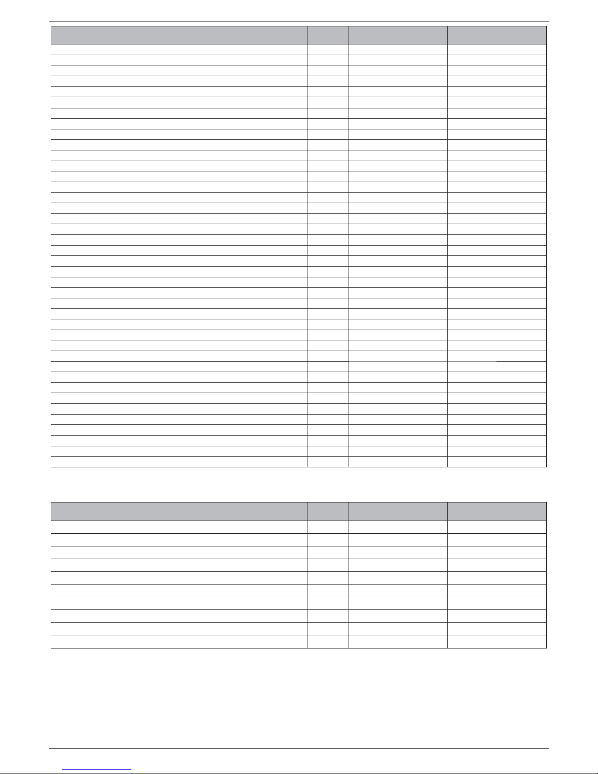
29
CALDERA EXCLUSIVE GREEN HE B.S.I.
DESCRIPCIÓN
CALDERA EXCLUSIVE
GREEN HE 25 B.S.I.
CALDERA EXCLUSIVE
GREEN HE 35 B.S.I.
Dimensiones de la caldera
Altura mm 940 940
Ancho mm 600 600
Profundidad a la cubierta mm 450 450
Peso de la caldera kg 65 72
Caudal (G20)
Capacidad de aire Nm3/h 31,135 43,090
Capacidad de gas de combustión Nm3/h 33,642 46,561
Caudal másico de gas de combustión (máx-mín) gr/s 11,282-1,070 15,614 - 1,498
Caudal (G31)
Capacidad de aire Nm3/h 31,752 43,945
Capacidad de gas de combustión Nm3/h 32,721 45,286
Caudal másico de gas de combustión (máx-mín) gr/s 11,046-1,988 15,288 - 2,740
Rendimiento del ventilador
Prevalencia residual caldera sin tubos Pa 98 199
Prevalencia residual tubos concéntricos 0,85 m Pa 40 60
Prevalencia residual tubos separados 0,5 m Pa 90 195
Tubos concéntricos de evacuación de humos
Diámetro mm 60-100 60-100
Longitud máxima m 7,85 7,85
Pérdida por la introducción de una curva de 45°/90° m 1,3/1,6 1,3/1,6
Agujero en la pared (diámetro) mm 105 105
Tubos concéntricos de evacuación de humos
Diámetro mm 80-125 80-125
Longitud máxima m 14,85 14,85
Pérdida por la introducción de una curva de 45°/90° m 1/1,5 1/1,5
Agujero en la pared (diámetro) mm 130 130
Tubos separados de evacuación de humos
Diámetro mm 80 80
Longitud máxima m 32+32 40+40
Pérdidas por curva de 45°/90° m
1/1,5 1/1,5
Instalación B23P-B53P
Diámetro mm 80 80
Longitud máxima conducto de evacuación m 50 60
Clase NOx 55
Valores de emisiones con caudal máximo y mínimo con gas G20*
Máximo - Mínimo CO s.a. inferior a ppm 180 - 5 180 - 10
CO
2
% 9 - 9,5 9 - 9,5
NOx s.a. inferior a ppm 45 - 10 35 - 15
Temperatura humos °C 76 - 59 74 - 62
* Control realizado con tubo concéntrico ø 60-100 - long. 0,85 m - temperatura agua 80-60°C
CALDERA EXCLUSIVE
GREEN HE 25 B.S.I.
CALDERA EXCLUSIVE
GREEN HE 35 B.S.I.
Tipo de depósito de agua Inoxidable Inoxidable
Disposición del depósito de agua Vertical Vertical
Disposición del intercambiador Vertical Vertical
Contenidos ACS l 60 60
Contenidos bobina l 3,87 3,87
Superfi cie de intercambio m
2
0,707 0,707
Campo de selección de la temperatura H2O sanitaria °C 35 - 60 35 - 60
Limitador de caudal l/min 15 15
Cantidad de agua caliente extraída en 10’ con Δt 30 °C l 202 202
Presión máxima del depósito de agua bar 8 8

30
CALDERA EXCLUSIVE GREEN HE B.S.I.
DESCRIPCIÓN Gas metano (G20) Propano (G31)
Índice de Wobbe inferior (a 15°C-1013 mbar) MJ/m3S 45,67 70,69
Poder calorífi co inferior
MJ/m
3
S
MJ/KgS
34,02
-
88
46,34
Presión nominal de alimentación
mbar
mm W.C.
20
203,9
37
377,3
Presión mínima de alimentación
mbar
mm W.C.
10
102
-
Caldera Exclusive Green HE 25 B.S.I.
Quemador: diámetro de boquillas - longitud mm - mm 63 - 130 63 - 130
Diafragma: número de orifi cios - diámetro de orifi cios n.° - mm 2 - 3,65 2 - 2,95
Caudal gas máximo calefacción Sm
3
/h 2,64
kg/h 1,94
Caudal gas máximo agua sanitaria Sm3/h 2,64
kg/h 1,94
Caudal gas mínimo calefacción Sm
3
/h 0,26
kg/h 0,35
Caudal gas mínimo agua sanitaria Sm
3
/h 0,26
kg/h 0,35
Número de revoluciones del ventilador en arranque lento revs/min 3.700 3.700
Número máximo de revoluciones del ventilador (CH) revs/min 6.000 6.000
Número máximo de revoluciones del ventilador (ACS) revs/min 6.000 6.000
Número mínimo de revoluciones del ventilador (CH) revs/min 1.200 1.900
Número mínimo de revoluciones del ventilador (ACS) revs/min 1.200 1.900
Caldera Exclusive Green HE 35 B.S.I.
Quemador: diámetro de boquillas - longitud mm - mm 63 - 140 63 - 140
Diafragma: número de orifi cios - diámetro de orifi cios n.° - mm 2 - 3,8 2 - 3,05
Caudal gas máximo calefacción Sm
3
/h 3,66
kg/h 2,69
Caudal gas máximo agua sanitaria Sm3/h 3,66
kg/h 2,69
Caudal gas mínimo calefacción Sm
3
/h 0,37
kg/h 0,48
Caudal gas mínimo agua sanitaria Sm
3
/h 0,37
kg/h 0,48
Número de revoluciones del ventilador en arranque lento revs/min 3.300 3.300
Número máximo de revoluciones del ventilador (CH) revs/min 6.000 5.900
Número máximo de revoluciones del ventilador (ACS) revs/min 6.000 5.900
Número mínimo de revoluciones del ventilador (CH) revs/min 1.200 1.900
Número mínimo de revoluciones del ventilador (ACS) revs/min 1.200 1.900
 Loading...