

Page 1

EXCLUSIVE C
Installer and user manual
RO
MANUAL DE INSTALARE SI UTILIZARE
ENESINSTALLER AND USER MANUAL
MANUAL DE INSTALACIÓN Y USO
Page 2

Installer’s-user’s manual 3-28
Boiler operating elements 40
Electric diagrams 41
Hydraulic circuit 42
Circulator residual head 43
EXCLUSIVE boiler complies with basic requirements of the
following Directives:
- Gas directive 2009/142/EC
- Efciencydirective:Article7(2)andAnnexIIIofdirective92/42/
EEC
- Electromagnetic compatibility directive 2014/30/EU
- Low-voltage directive 2014/35/EU
- Directive 2009/125/EC Ecodesign for energy-using appliances
- Directive 2010/30/EU Indication by labelling of the consumption
of energy by energy-related products
- DelegatedRegulation(EU)No.811/2013
- DelegatedRegulation(EU)No.813/2013
- DelegatedRegulation(EU)No.814/2013.
EN
In some parts of the booklet, some symbols are used:
b
WARNING = for actions requiring special care and adequate
preparation.
a
PROHIBITED =foractionsTHATMUSTNOTbeperformed.
Sectiondestinedforuseralso.
Warning
This instructions manual contains data and information for both the user and
theinstaller. Specically,note that the user,for the use of the appliance,
must refer to chapters:
• Warnings and safety
• Maintenance
a
The user must not perform operations on the safety devices,
replacing parts of the product, tamper with or attempt to repair
the appliance. These operations must be entrusted exclusively
professionallyqualiedpersonnel.
b
The manufacturer is not liable for any damage caused by the
non-observance of the above and/or the failure to comply with the
regulations.
RANGE RATED
Thisboilercanbeadaptedtotheheatrequirementsofthesystem,andinfactitispossibletosettherangeratedparameterasshowninthespecic
paragraph.
Putthesetvalueontheadhesivelabelsuppliedand,forsuccessivecontrols,refertothenewvalue.
0476
0476CS1393
Page 3

3
ENGLISH
1 WARNINGS AND SAFETY
b
The boilers manufactured in our factories are checked even in
the smallest details in order to protect users and installers against
possible injury. After working on the product, qualied personnel
must check the electrical wiring, in particular the stripped part of
leads, which must not protrude from the terminal board and avoiding
possible contact with live parts of the leads themselves.
b
This installer and user manual constitutes an integral part of the
product: make sure they are always kept with the appliance, even
if it is transferred to another owner or user, or moved to another
heating system. In case of loss or damage, please contact your local
Technical Assistance Service for a new copy.
b
This boiler may only be installed and serviced by personnel qualied
in accordance with current regulations.
b
The installer must instruct the user about the operation of the
appliance and about essential safety regulations.
b
This boiler must only be used for the application it was designed for.
The manufacturer accepts no liability within or without the contract
for any damage caused to people, animals and property due to
installation, adjustment and maintenance errors or to improper use.
b
After removing the packaging, make sure the content is in good
condition and complete. Otherwise, contact the dealer from whom
you purchased the appliance.
b
The safety valve outlet must be connected to a suitable collection
and venting system. The manufacturer declines all liability for any
damage caused due to any intervention carried out in the safety
valve.
b
The seal of the condensate drainage connection line must be secure,
and the line must be fully protected against the risk of freezing (e.g.
by insulating it).
b
Check that the rain water drainage channel of the ue gases tting
and the relative connection pipe are free of obstructions.
b
Dispose of all the packaging materials in the suitable containers at
the corresponding collection centres.
b
Dispose of waste by being careful not to harm human health and
without employing procedures or methods which may damage the
environment.
b
At the end of its life, the product should be not be disposed of as solid
urban waste, but rather it should be handed over to a differentiated
waste collection centre.
b
During installation, inform the user that:
- in the event of water leaks, the water supply must be shut off and
the Technical Assistance Centre must be contacted immediately
- periodically check that the operating pressure of the hydraulic
system is comprised between 1 and 1.5 bar. If it is not, request
the prompt intervention of the Technical Assistance Centre or else
professionally qualied personnel.
b
If the boiler is not used for a long period of time, it is recommended
to perform the following operations:
- turn the main appliance switch and the main system switch to “off”
- close the fuel and water valves for the heating and domestic hot
water system
- empty the heating and domestic hot water circuits if there is the
risk of freezing
b
Boiler maintenance must be carried out at least once a year; this
should be booked in advance with the Technical Assistance Centre
to ensure the necessary safety standards.
For safety reasons, please remember that:
a
The appliance is not to be used by children or unassisted people with
disabilities.
a
It is forbidden to touch the appliance while barefoot or if parts of your
body are wet.
a
It is forbidden to activate electric devices or appliances such as
switches, household appliances and so on if you notice a smell of
fuel or unburned fuel. In this case:
- ventilate the room by opening the doors and windows;
- close the fuel shut-off device;
- request the prompt intervention of the Technical Assistance Centre
or else professionally qualied personnel.
INSTALLATION MANUAL
EN
ENGLISH
a
Any technical or cleaning operation is forbidden before disconnecting
the appliance from the main power supply by turning the system’s
main switch to “OFF” and the main switch of the boiler to “OFF”.
a
Do not modify the safety or adjustment devices without the
manufacturer’s authorisation and precise instructions.
a
It is prohibited to pull, detach or twist the electrical cables coming
from the appliance even if it is disconnected from the mains power
supply.
a
Avoid blocking or reducing the size of the air vent openings in
the installation room, do not leave inammable containers and
substances in the room where the appliance is installed.
a
Do not leave ammable containers and substances in the room
where the device is installed.
a
It is forbidden to disperse the packaging material in the environment
and leave it within children’s reach as it may be a potential source
of danger. It must be disposed in accordance with the present law.
a
The condensate drain outlet must be turned towards the drain outlet
avoiding the formation of more siphons.
a
Never carry out any work on the gas valve.
2
DESCRIPTION
The EXCLUSIVE boilers have a new ACC (Activate Combustion Control)
system.
This new control system, developed by Beretta, ensures functionality,
efciency and low emissions under any conditions.
The ACC system uses an ionisation sensor immersed in the burner ame,
whose information allows the control board to operate the gas valve that
regulates the fuel.
This sophisticated control system provides the auto-regulation of the
combustion, so there is no need for an initial calibration. The ACC system is
able to adapt the boiler to operate with different gas compositions, different
outlet pipes lengths and different altitudes (within the specied design
limits).
The ACC system can also perform an auto-diagnostic operation that locks
out the burner before the permitted upper emission limit is exceeded.
EXCLUSIVE is a type C condensing wall-hung boiler to be used for heating
and the production of domestic hot water: depending on the fume discharge
accessory used, it is classied in categories B23P;B53P; C13,C13x;
C33,C33x; C43,C43x; C53,C53x; C63,C63x; C83, C83x; C93, C93x.
In B23P conguration (when installed indoors), the appliance cannot
be installed in bedrooms, bathrooms, showers or where there are open
replaces without a proper air ow. The room where the boiler is installed
must have proper ventilation. Detailed requirements for the installation of
the ue, the gas piping and for ventilating the room, can be found in UNI
7129-7131.
In conguration C, the appliance can be installed in any type of room (there
are no limitations due to ventilation conditions or room volume).
3 INSTALLATION
3.1 Cleaning the system and characteristics of the
water
In the case of a new installation or replacement of the boiler, it is necessary
to clean the heating system.
To ensure the device works well, top up the additives and/or chemical
treatments (e.g. anti-freeze liquids, lming agents, etc.) and check the
parameters in the table are within the values indicated.
PARAMETERS UM
HEATING CIRCUIT
WATER
FILLING WATER
pH value 7-8 Hardness °F - 15-20
Appearance - clear
b
Before installation, wash all system piping carefully in order to
remove any residues that may impair the operation of the appliance.
Page 4

4
EXCLUSIVE
b
Under the safety valve, install a water collecting funnel with the
corresponding discharge in the event of leaks due to the overpressure
of the heating system. The domestic hot water circuit does not need a
safety valve, but make sure that the pressure of waterworks does not
exceed 6 bar. In case of doubts, install a pressure reducer.
b
Prior to ignition, make sure that the boiler is designed to operate
with the gas available; this can be checked by the wording on the
packaging and by the adhesive label indicating the gas type.
b
It is very important to highlight that in some cases the ues are under
pressure, so the joints of the various elements must be airtight.
3.2 Installation regulations
The installation must be carried out by qualied personnel, in compliance
with the following reference standards:
- UNI 7129-7131
- CEI 64-8.
Always comply with local standards of the Fire Department, the Gas
Company and with possible municipal dispositions.
POSITION
EXCLUSIVE is a wall-hung boiler for heating and for the production of hot
water. There are two categories, depending on the type of installation:
- B23P-B53P boiler type - forced open installation, with ue gas discharge
pipe and pick-up of combustion air from the installation area. If the
boiler is not installed outdoors, the air intake in the installation area is
compulsory;
- C13,C13x; C33,C33x; C43,C43x; C53,C53x; C63,C63x; C83,C83x,
C93,C93x type boiler: appliance with airtight chamber, with ue gas
discharge pipe and pick-up of combustion air from outside.
It does not require an air intake point in the installation area.
This type MUST be installed using concentric pipes, or other types of
discharge designed for condensing boilers with an airtight chamber.
MINIMUM DISTANCES (g. 6-6a)
To ensure access to the boiler for normal maintenance operations, respect
the minimum installation clearances envisaged.
For correct appliance positioning, bear in mind that:
- it must not be placed above a cooker or other cooking device
- it is forbidden to leave inammable products in the room where the boiler
is installed
- heat-sensitive walls (e.g. wooden walls) must be protected with proper
insulation.
b
In case of installation it is ESSENTIAL to provide the necessary
space for the introduction of the instrument for the combustion
analysis check. In g. 6a is shown a sample drawing where the
distances between boiler and cabinet/niche were obtained using a
300mm length tool.
Longer lengths of tools require more space.
3.3 Elimination of air from the heating circuit and
from the boiler - g. 7
During the initial installation phase, or in the event of extraordinary
maintenance, you are advised to perform the following sequence of
operations:
1. Open by two or three turns the automatic relief valve cap (A) and leave
it open.
2. Open the system lling tap located on the water unit.
3. Switch on the electricity supply to the boiler, leaving the gas tap turned
off.
4. Activate a heat request via the room thermostat or the remote control
panel, so that the 3-way valve goes into heating mode.
5. Activate a request for DHW as follows: open a tap for 30” per minute so
that the three-way valve cycles from heating to DHW and vice versa for
about ten times (in this situation, the boiler will go into alarm due to lack
of gas, therefore reset it whenever this is proposed).
6. Continue the sequence until no more air is felt coming from the air vent
valve.
7. Check the system pressure level is correct (the ideal level is 1 bar).
8. Turn off the system lling tap.
9. Turn on the gas tap and ignite the boiler.
3.4 Positioning the wall-mounted boiler and hydraulic
connections - g. 8-9
The boiler comes as standard with a boiler support plate. The position and
dimension of hydraulic ttings are shown in the detail drawing.
For the assembly, proceed as follows:
- fasten the boiler support plate (F) to the wall and use a spirit level to
make sure it is perfectly horizontal
- mark the 4 holes (ø 6 mm) envisaged for securing the boiler support
plate (F)
- make sure that all measurements are exact, then drill the wall using drill
tips with the diameters indicated above
- x the plate with the built-in template to the wall
- carry out the hydraulic connections.
3.5 Electrical wiring - g. 10-11
Low voltage connections
Carry out the low voltage connections as follows:
- use the external cable box supplied as standard
- unscrew the xing screws of the cover (V)
- carry out the connections as shown in g. 11
b
It is recommended to use wires with section not exceeding
0,5mm2.
b
In case of TA or TBT connection, remove the respective shunts
(g. 12).
- close the box with the screws that were previously removed
- press the two tabs on the sides of the box to place it correctly in its
housing in the boiler sliding upward within the guide rails
- tighten the safety screw (V1).
b
If the low voltage electrical connection box is not connected the
boiler does not ignite.
High voltage connections
The connection to the mains supply must be made via a separation device
with an omnipolar opening of at least 3.5 mm (EN 60335/1 - category 3).
The appliance works with alternating current at 230 Volt/50 Hz, and is in
compliance with Standard EN 60335-1.
It is obligatory to make the connection with a safe ground/earth, in
compliance with current directives.
b
It is the responsibility of the installer to provide suitable grounding
for the appliance; the manufacturer will not be liable for any damage
resulting from an incorrect or absent earth connection.
b
It is also recommended to uphold the phase-neutral connection (L-N).
b
The earth conductor must be a couple of cm longer than the others.
The boiler can operate with a phase-neutral or phase-phase supply.
For power supplies that are not earthed, it is necessary to use an isolating
transformer with earth-anchored secondary.
It is forbidden to use gas and/or water pipes to earth electrical appliances.
Use the power cable supplied to connect the boiler to the mains power
supply.
If the power cable has to be replaced, use a HAR H05V2V2-F cable, 3 x
0.75mm2, Ø max external 7 mm.
3.6 Gas connection
The connection of the gas supply must be carried out in compliance with
current installation standards.
Before carrying out the connection, check that the type of gas is that for
which the appliance is set up.
3.7 Removing the casing
To access the components inside, remove the casing as indicated below:
- locate and unscrew the 2 screws (A - g. 13) that x the casing to the
boiler
- by leveraging the xing clips (C - g. 13), unhook the lower part of the
casing
- lift the casing upwards to release it from the top tabs (B - g. 13), then
remove it.
WARNING
b
The possible damage of the frontal panel involves the replacement
of the same.
b
The noise absorbing panels inside the front and side walls ensure
the airtight seal for the air supply duct in the installation environment.
b
It is therefore ESSENTIAL after the dismantling operations to
correctly reposition the components so as not to compromise the
boiler’s operation.
3.8 Flue gas exhaust and combustion air suction
To evacuate the combustion products, refer to UNI 7129-7131. Always
comply with local standards of the Fire Department, the Gas Company and
with possible municipal dispositions.
The release of combustion products is assured by a centrifugal fan and the
control board constantly checks that it is operating correctly. It is essential
for evacuating fumes and adduction boiler combustion air that only original
pipes are used and that the connection is made correctly as shown in the
instructions provided with the ue gas accessories.
A single ue can be connected to several appliances provided that every
appliance is the condensing type.
Page 5
5
ENGLISH
The boiler is a C-type appliance (with airtight chamber), and must therefore
have a safe connection to the ue gas discharge pipe and to the combustion
air suction pipe; these both carry their contents outside, and are essential
for the operation of the appliance.
Both concentric and twin terminals are available.
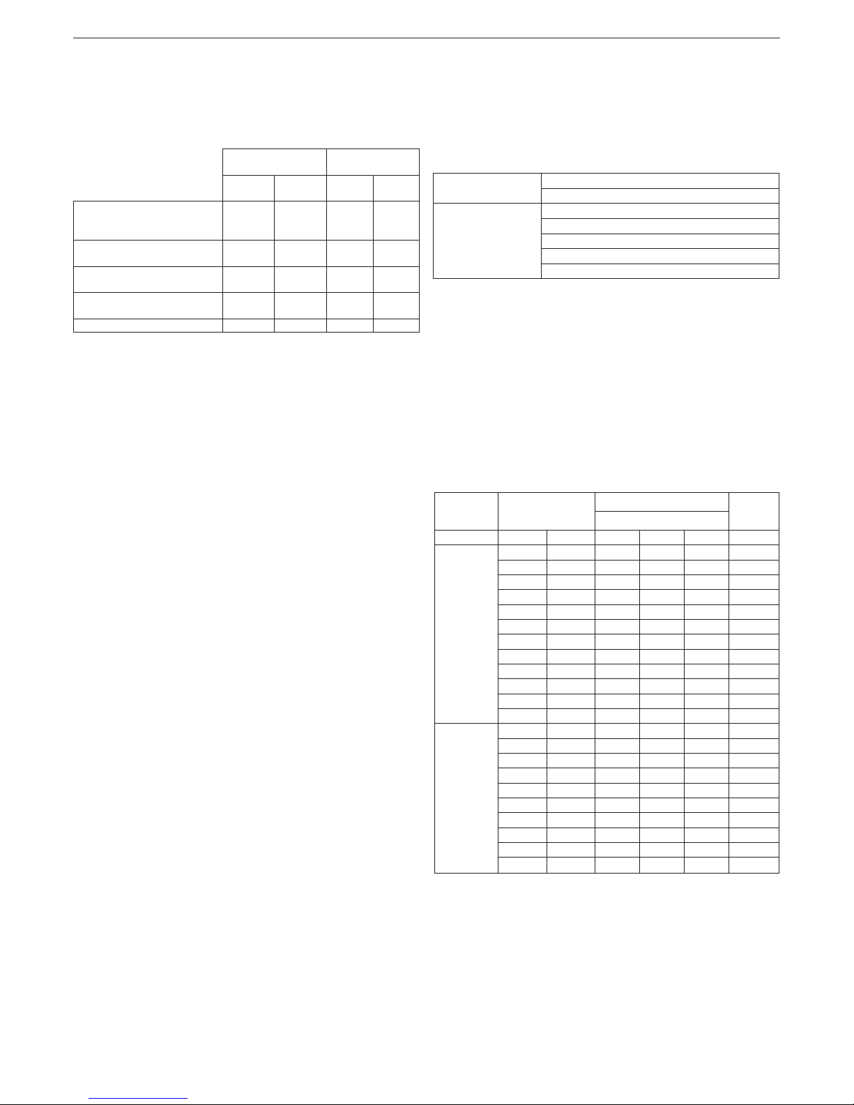
Suction/discharge pipes length table
Maximum straight
length
Pressure drop
25C n 30C n
bend
45°
bend
90°
Flue gases pipe Ø 80 mm
(“forced open” installation)
(type B23P-B53P)
125 m 90 m 1 m 1,5 m
Concentric pipe
Ø 60-100 mm (horizontal)
10 m 10 m 1,3 m 1,6 m
Concentric pipe
Ø 60-100 mm (vertical)
11 m 11 m 1,3 m 1,6 m
Concentric pipe
Ø 80-125 mm
25 m 25 m 1 m 1,5 m
Twin pipe Ø 80 mm 70+70 m 50+50 m 1 m 1,5 m
b
“Straight length” means with terminals and joints but without bends.
b
The boi
ler is supplied without the ue gas outlet/air suction kit, since
it is possible to use the accessories for condensing appliances that
better adapt to the installation characteristics (see catalogue).
b
The maximum lengths of the pipes refer to the ue accessories
available in the catalogue.
b
It is compulsory to use specic pipes.
b
The non insulated ue gas outlet pipes are potential sources of
danger.
b
The use of a longer pipe causes a loss of output of the boiler
b
Make sure the ue gas discharge pipe is tilted 3° towards the boiler.
b
As envisaged by current legislation, the boiler is designed to take
in and dispose of ue gas condensate and/or meteoric water
condensate deriving from the ue gas discharge system using its
own siphon.
b
If a condensate relaunch pump is installed, check the technical
data (provided by the manufacturer) regarding output, to ensure it
operates correctl.
“Forced open” Installation (type B23P/B53P)
In this conguration the boiler is connected to the ø 80 mm ue gases
discharge pipe by means of an adaptor.
- Position the adaptor so that the Ø 60 pipe goes fully into the ue gases
turret of the boiler.
- Once positioned, make sure that the 4 notches (A) on the ange connect
to the groove (B) on the Ø100 of the adaptor.
- Fully tighten the two locking terminals of the ange (C) so the adaptor
itself is restrained.
Concentric pipes (ø 60-100 mm)
- Position the bend so that the Ø 60 pipe goes fully into the ue gases
turret of the boiler.
- Once positioned, make sure that the 4 notches (A) on the ange connect
to the groove (B) on the Ø100 of the bend.
- Fully tighten the two locking terminals of the ange (C) so the bend itself
is restrained.
Twin pipes (ø 80 mm) - see graphs g. 18
The combustion air suction pipe should be selected from the two inputs,
remove the closing plug xed with the screws and x the specic air
deector.
- Position the adaptor on the ue gases pipe so that the Ø 60 pipe goes
fully into the ue gases turret of the boiler
- Once positioned, make sure that the 4 notches (A) on the ange connect
to the groove (B) on the Ø100 of the adaptor.
- Fully tighten the two locking terminals of the ange (C) so the adaptor
itself is restrained.
Concentric pipes (ø 80-125 mm)
- Position the adaptor so that the Ø60 pipe goes fully into the ue turret
of the boiler.
- Once positioned, make sure that the 4 notches (A) on the ange connect
to the groove (B) on the Ø100 of the adaptor.
- Fully tighten the two locking terminals of the ange (C) so the adaptor
itself is restrained.
- Then t the Ø 80-125 adaptor kit on the vertical tting.
Twin pipes ø 80 with ducting Ø50 - Ø60 - Ø80 (g. 15a)
Thanks to the boiler characteristics, a ue gas discharge pipe ø 80 can
be connected to the ducting ranges Ø50 - Ø60 - Ø80.
b
For the ducting, you are advised to make a project calculation in
order to respect the relevant standards in force.
The table shows the standard congurations allowed.
Table of standard pipe configurations (*)
Air suction
1 bend 90° ø 80
4,5m pipe ø 80
Flue gas discharge
1 bend 90° ø 80
4,5m pipe ø 80
Reduction from ø 80 to ø50, from ø 80 to ø 60
Stack base bend 90°, ø 50 or ø 60 or ø 80
For ducting pipe lengths see table
(*) Use ue gas system accessories in plastic (PP) for condensing boilers:
Ø50 and Ø80 H1 class and Ø60 P1 class.
The boilers are factory set to:
25C n: 5.600 r.p.m. (CH) and 7.900 r.p.m. (DHW) and the maximum length
that can be reached is 6m for the ø 50 pipe, 21m for the ø 60 pipe and 115m
for the ø 80 pipe.
30C n: 6.500 r.p.m. (CH) and 7.900 r.p.m. (DHW) and the maximum length
that can be reached is 4m for the ø 50 pipe, 16m for the ø 60 pipe and 83m
for the ø 80 pipe.
Should it be necessary to achieve greater lengths, compensate the pressure drop with an increase in the r.p.m.of the fan, as shown in the adjustments table, to ensure the rated heat input.
b
The minimum calibration is not modied.
Adjustments table
Maximum number
of fan rotations
r.p.m.
Ducting pipes
ΔP at
boiler
output
maximum length (m)
CH DHW Ø 50 Ø 60 Ø 80 Pa
25C n
5.600 7.900 6 21 115 180
5.600 8.000 8 (*) 25 (*) 139 (*) 210
5.700 8.100 10 (*) 32 (*) 175 (*) 255
5.700 8.200 12 (*) 35 (*) 195 (*) 280
5.800 8.300 14 (*) 42 (*) 231 (*) 325
5.900 8.400 17 (*) 48 (*) 263 (*) 365
6.000 8.500 19 (*) 53 (*) 291 (*) 400
6.100 8.600 22 (*) 60 (*) 331 (*) 450
6.200 8.700 24 (*) 66 (*) 363 (*) 490
6.200 8.800 26 (*) 71 (*) 389 (*) 523
6.300 8.900 28 (*) 76 (*) 420 (*) 562
6.400 9.000 31 (*) 82 (*) 452 (*) 601
30C n
6.500 7.900 4 16 83 190
6.600 8.000 5 (*) 19 (*) 103 (*) 225
6.700 8.100 7 (*) 24 (*) 128 (*) 270
6.800 8.200 9 (*) 28 (*) 151 (*) 310
6.900 8.300 11 (*) 33 (*) 174 (*) 350
7.000 8.400 13 (*) 37 (*) 196 (*) 390
7.100 8.500 14 (*) 40 (*) 213 (*) 420
7.200 8.600 16 (*) 44 (*) 236 (*) 460
7.300 8.700 17 (*) 48 (*) 256 (*) 495
7.400 8.800 19 (*) 53 (*) 281 (*) 540
(*) Maximum installable length ONLY with exhaust pipes in H1 class.
Congurations Ø50 or Ø60 or Ø80 show test data veried in the laboratory.
In the case of installations that differ from those indicated in the “standard
conguration” and “adjustments” tables, refer to the equivalent linear
lengths below.
b
In any ca
se, the maximum lengths declared in the booklet are
guaranteed, a
nd it is essential not to exceed them.
Page 6
6
EXCLUSIVE
COMPONENT Ø 50 Linear equivalent in metres Ø80 (m)
Bend 45° Ø 50 12,3
Bend 90° Ø 50 19,6
Extension 0.5m Ø 50 6,1
Extension 1.0m Ø 50 13,5
Extension 2.0m Ø 50 29,5
COMPONENT Ø 60 Linear equivalent in metres Ø80 (m)
Bend 45° Ø 60 5
Bend 90° Ø 60 8
Extension 0.5m Ø 60 2,5
Extension 1.0m Ø 60 5,5
Extension 2.0m Ø 60 12
3.9 Filling the heating system (g. 16)
Note: even if the boiler is tted with a semi-automatic lling device, the
rst lling operation must be carried out by turning the ller tap (B) with the
boiler off.
Once the hydraulic connections have been carried out, ll the heating
system.
This operation must be carried out when the system is cold,carrying out the
following operations:
- open the cap of the lower (A) automatic air vent valve by two or three
turns; to allow a continuous venting of the air, leave the plug of the valve
A open
- make sure the cold water inlet tap is open
- open the lling tap (B) until the pressure indicated by the water pressure
gauge is between 1 and 1.5 bar
- re-close the lling tap.
b
The venting of the boiler takes place automatically via the two
automatic vent valve A positioned on the circulator.
3.10 Draining the heating system (g. 16)
Before starting emptying, switch off the electricity supply by turning off the
main switch of the system.
- Close the heating system’s valves.
- Connect a hose to the system drain valve (C).
- Manually loosen the system drain valve (C).
3.11 Emptying the domestic hot water system
Whenever there is risk of frost, the domestic hot water system must be
emptied in the following way:
- turn off the main water supply tap
- turn on all the hot and cold water taps
- drain the lowest points.
3.12 Circulator settings
Circulator residual discharge head
The boilers is equipped with an already hydraulically and electrically
connected circulator, whose useful available performance is indicated in
the graphs at page 43.
The circulator comes set from the factory with a 6 metre discharge head curve.
The boiler is equipped with an anti-blocking system which starts up an
operation cycle after every 24 hours in standby with the mode selector in
any position.
b
The “antiblocking” function is active only if the boiler is electrically
powered.
a
Operating the circulator without water is strictly forbidden.
If you need to use a different curve you can select the desired level on the
circulator.
Below the main characteristics and the ways to set up their desired operation
are listed.
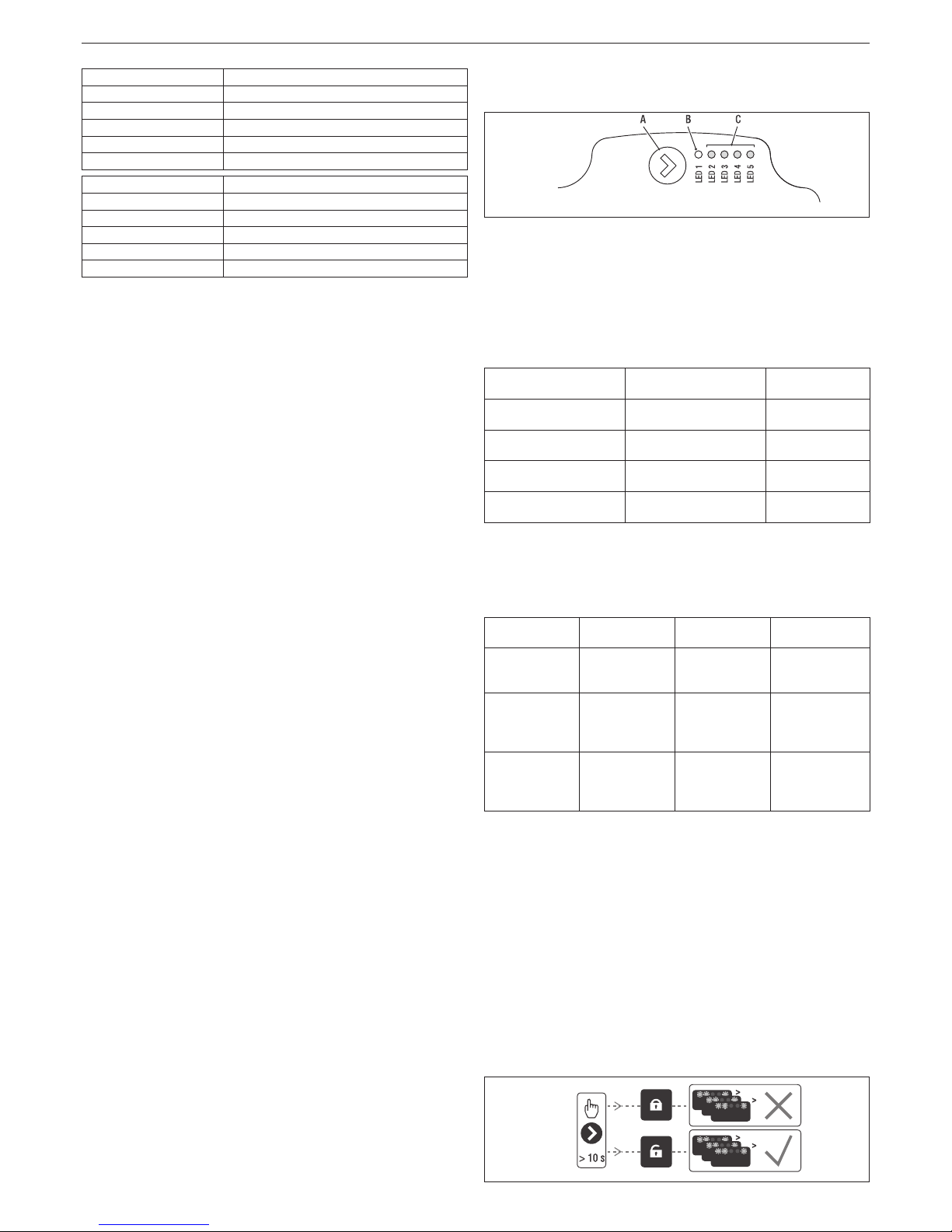
3.12.1 User interface
The user interface is made up of a button (A), a two-coloured red / green
LED (B) and four yellow LEDs (C) arranged in a row.
The user interface allows the operating performance to be viewed (operating
status and alarm status) and it also allows the circulator operating modes
to be set.
The performance, indicated by the LEDs (B) and (C) is always visible during
normal operation of the circulator whereas the settings can be carried out
by pressing the button (A).
3.12.2 Operating status indication
When the circulator is in operation the LED (B) is green. The four yellow
LEDs (C) indicate the electrical energy consumption (P1) as shown in the
following table.
LED status CIRCULATOR status
Consumption in
% of MAX P1 (*)
Green LED on +
1 yellow LED on
Operating at minimum 0~25
Green LED on +
2 yellow LEDs on
Operating at
minimum-medium
25~50
Green LED on +
3 yellow LEDs on
Operating at medium-
maximum
50~75
Green LED on +
4 yellow LEDs on
Operating at maximum 100
(*) For the power (P1) absorbed by the circulator see the indications in the
“Technical Data” table.
3.12.3 Alarm status indication
If the circulator has detected one or more alarms the two-coloured LED (B)
will be red. The four yellow LEDs (C) indicate the type of alarm as shown
in the following table.
LED status
ALARM
description
Status
CIRCULATOR
Possible
SOLUTION
Red LED on +
1 yellow LED
on (LED 5)
The drive shaft
is jammed
Start attempt
every 1.5
seconds
Wait or unjam
the drive shaft
Red LED on +
1 yellow LED
on (LED 4)
Low input
voltage
Warning only.
The circulator
continues to
operate
Check the
input voltage
Red LED on +
1 yellow LED
on (LED 3)
Electrical power
supply fault or
faulty circulator
The circulator
is stopped
Check the
electrical power
supply or replace
the circulator
b
If there a
re several alarms the circulator will display only the alarm
with the highest priority.
3.12.4 Display of active settings
With the circulator powered, press briey on the button (A) to view the active
conguration of the circulator. The LEDs indicate the active settings.
In this phase no variations can be made to the circulator conguration. Two
seconds after the button (A) has been pressed the user interface returns to
the normal operating status display.
3.12.5 Key lock function
The purpose of the key lock function is to prevent accidental modications
to the settings or the improper use of the circulator.
When the key lock function is activated, long-pressing the button (A) is
prevented. This prevents the user from entering the circulator’s operating
modes setting section.
Enabling/disabling the key lock function is achieved by pressing the button
(A) for more than 10 seconds. During this step all of the LEDs (C) will ash
for 1 second.
Page 7

7
ENGLISH
3.12.6 Changing the operating mode
In normal operating conditions the circulator works with the factory settings
or the last settings carried out.
To change the conguration:
Ensure that the key lock function is deactivated.
Press the button (A) for more than 2 seconds until the LEDs begin to ash.
Short-press the button (A) within 10 seconds and the user interface will move
on to display the next settings. The various available settings will appear in
a cyclic sequence.
If the button (A) is not pressed, the last setting will be stored.
A
B
C
A. Operating status display
B. Settings display
C. Settings
Conguración
If the button (A) is pressed you can move back to the “active settings display”
again and check that the LEDs (B) and (C) indicate (for 2 seconds) the last
setting carried out.
If the button (A) is not pressed for more than 2 seconds the user interfaces
switches to the “Operating status display”.
The available settings are shown in gure along with the related representation
of LED (B) and (C).
(*)
LED 1RLED 2GLED 3GLED 4GLED 5
G
(*) Factory set value
R red
G yellow
IM
PORTANT
If the 3 (5 metres) or 4 (4 metres) curves are set the bypass must be replaced
with the one supplied, following the procedure indicated below:
Remove boiler electrical power by setting the system’s main switch to off.
Close the system taps and empty the boiler heating circuit.
Extract the bypass body cover xing spring (D).
Extract the bypass body cover (E).
Replace the bypass valve (F) with the one included.
Ret the bypass body cover and its spring.
D
F
E
Page 8
8
EXCLUSIVE
This icon indicates that the OFF operating status mode has been set. Each ignition request is ignored except for the anti-freeze function. The pump
anti-lock, 3-way valve and anti-freeze function remain active.
This icon indicates that WINTER mode has been selected (HEATING function enabled). If a heating request from the main zone is in progress, the
icon will be flashing.
This icon indicates that the circuit for domestic hot water production is enabled. When a domestic hot water request is in progress, the icon flashes.
The P at the top of the domestic hot water icon indicates that the boiler preheating function is enabled; the P when flashing indicates that a preheating
request is in progress.
When the “central heating programming timing” is enabled this icon indicates that the system heating (main zone) is in AUTOMATIC mode (the
management of the heating requests follows what has been set with the timer).
If the heating function is not enabled during the current time frame, the icon will be crossed out.
When the “central heating programming timing” is enabled this icon indicates that the system heating (main zone) is in MANUAL mode (the
management of the heating requests does not follow what has been set with the programming timing, but it is always active).
OFF This icon indicates that the system (main zone) has been set to off (not active).
This icon indicates that the system is detecting the presence of a flame.
This icon indicates the presence of an anomaly, and is always flashing.
FRI
18/05/2013
12:17
MENU
INFO SET
PLANT
HOT WATER TEMPERATURE
STATE
42
°C
P
1.3
bar
LED
REC10
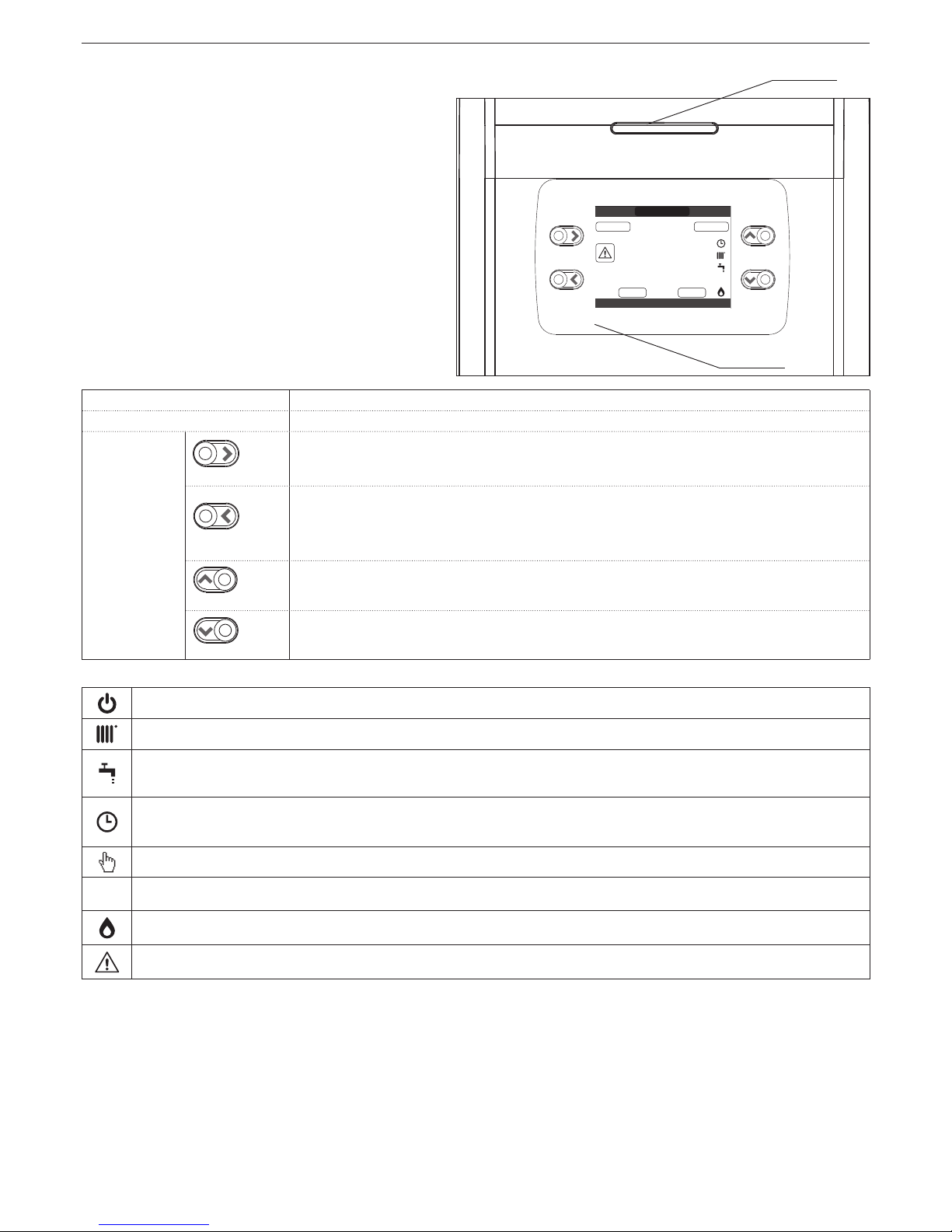
4 CONTROL PANEL (REC10)
The REC10 remote control has the function of machine interface,
displaying the system and providing access to the parameters.
The middle of the main screen displays the temperature of the domestic
hot water probe, unless there is a heat request is in progress, in this
case the delivery temperature of the boiler at that particular time is
displayed.
The value expressed in bar refers to the system’s water pressure.
The top of the screen shows the information regarding the current date
and time, as well as the outdoor temperature, if available.
On the left and right sides are displayed the icons indicating the status
of the system; their meaning is as follows.
Pressing the keys
“up” and “down”
it is possible to choose from among
the following options:
• PLANT: a scrolling message on the display can indicate the temperature
of the domestic hot water probe rather than the flow sensor of the boiler
• STATE (when the SYSTEM SCREEN is selected): to set the status
of the boiler (OFF, SUMMER or WINTER) and, when managed by the
room thermostat, the operating mode of the main area in heating mode
(ON or OFF if the time schedule is disabled, AUTO according to hourly
programming, MANUAL or OFF if programming timing is enabled)
• SET: to establish the heating or hot water setpoint value or for activating
preheating
• INFO: to display the value of the system variables
• MENU: to access the system’s configuration menus
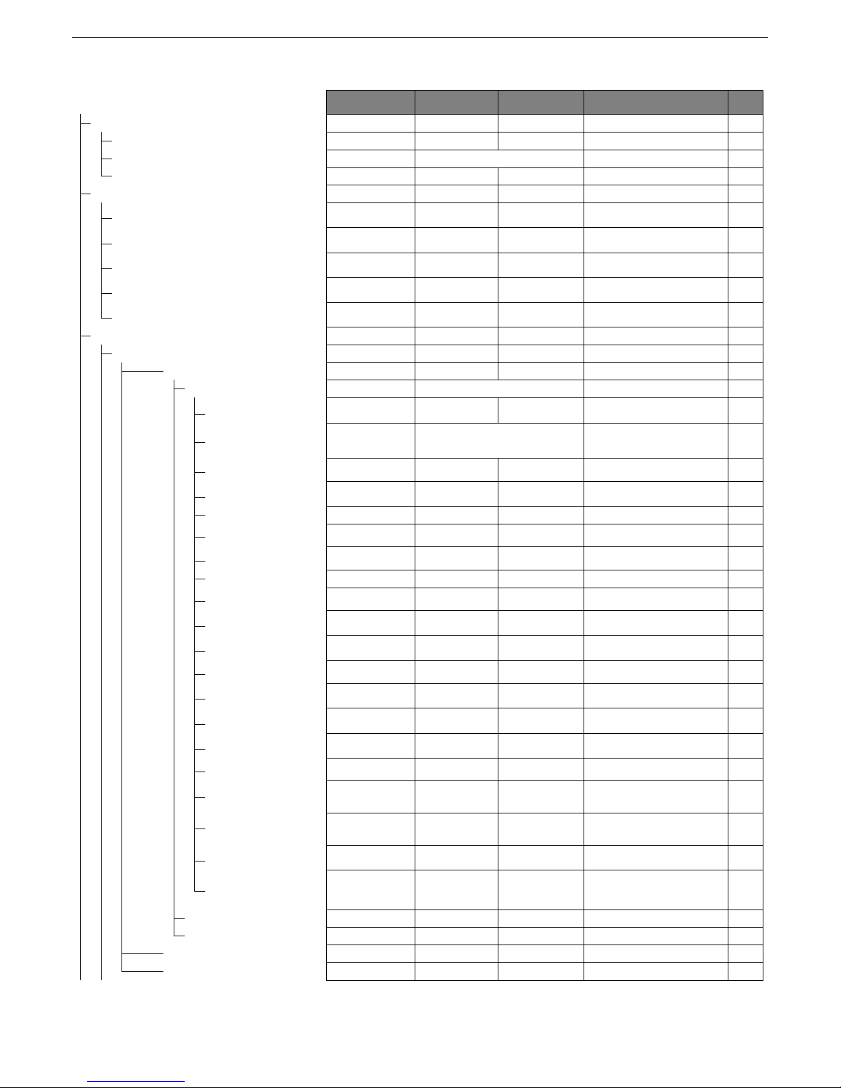
The configuration MENU is organised with a multi-level tree structure. With
the “ok” key you can access the selected submenu, with the
“up” and
“down”
keys it is possible to navigate through the submenus, while the
“back/cancel” key takes you back to the previous level.
An access level has been fixed for each submenu: USER level, always
available; TECHNICAL level, password protected.
Below is a summary of the MENU tree structure of the REC10.
b
Some of the information might not be available on the REC10
depending on the access level, the status of the machine or the
system conguration.
LED
Light signal indicating the operating status of the boiler. Can be red or green (see specific paragraph)
REC10
Boiler control panel
Key area
ok= confirm
back= ret
urn to the previous screen
cancel selection
return to the main screen (press > 2 sec.)
up= allows you to choose between the options PLANT-STATE-SET-INFO-MENU and to
surf through the
submenus
scrolling upwards
down= allows you to choose between the options PLANT-STATE-SET-INFO-MENU and to
surfe through the
submenus
scrolling down
cancel=
Page 9
9
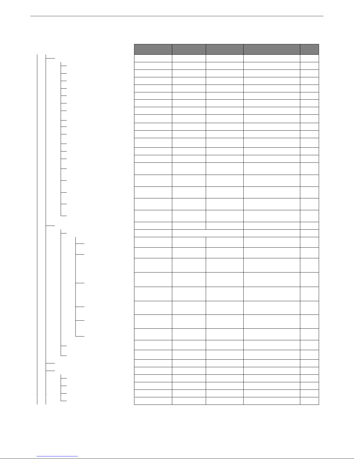
ENGLISH
MENU
DEFAULT VALUE
MINIMUM
VALUE
MAXIMUM
VALUE
ACCESS LEVEL
NOTES
SET
VALUE
SETTINGS
USER
TIME & DATE
USER
LANGUAGE
ITALIANO / ENGLISH USER
BACKLIGHT
5 min 1 min 15 min USER
TIME SCHEDULE
USER
MAIN
USER
Only if POR = 1
ZONE1
USER
Only if POR = 1
ZONE2
USER
Only if POR = 1
DHW
USER
DHW HEAT PUMP
USER
TECHNICAL
INSTALLER
INSTALLATION
INSTALLER
ZONES MANAGER
INSTALLER
MODIFY ZONE MAIN MAIN / ZONE1 / ZONE2 INSTALLER
ACTUATION TYPE
ITRF05/AKM ITRF05/AKM BE16
INSTALLER
Only MAIN zone
REQUEST TYPE THERMOSTAT
THERMOSTAT / TEMPERATURE PROBE /
REC10 MASTER / REC10 SLAVE
INSTALLER
BE16 ADDRESS - - 1 6
INSTALLER
Only zones with
ACTUATION = BE16
HYDRAULIC CONF DIRECT ZONE DIRECT ZONE MIXING ZONE
INSTALLER
Only zones with ACTUATION = BE16
ZONE TYPE HIGH TEMP. HIGH TEMP. LOW TEMP. INSTALLER
MIN CH SET
40°C (AT)
20°C (BT)
20°C MAX CH SET INSTALLER
MAX CH SET
80,5°C (AT)
45°C (BT)
MIN CH SET
80,5°C (AT)
45°C
(BT)
INSTALLER
CHANGE NAME
INSTALLER
PI - PROPORTIONAL 5 0 99
SERVICE
Only mixing z ones with A
CTUATION=BE16
PI - INTEGRAL 10 0 99
SERVICE
Only mixing z ones with ACTUATION=BE16
VALVE RUN 120 sec 0 sec 240 sec
SERVICE
Only mixing z ones with ACTUATION=BE16
CLOSING AT POWE R ON 140 sec 0 sec 240 sec
SERVICE
Only mixing z ones with ACTUATION=BE16
OUTLET OVER 55°C 0°C 100°C
SERVICE
Only BT zones with A CTUATION =BE16
OUTLET OVER TEST TIME 0min 0min 240min
SERVICE
Only BT zones with A CTUATION =BE16
OUTLET OVER WAIT TIME 2mi n VALVE RUN 240min
SERVICE
Only BT zones with A CTUATION =BE16
OUTLET OVER REST TIME 2min 0min 240min
SERVICE
Only
BT zones with ACTUATION =BE16
FREEZE PROT TEMP 6°C -20°C 50°C
SERVICE
Only zones with ACTUATION = BE16
FREEZE PROT OFFSET ZONE 5°C 1°C 20°C
SERVICE
Only zones with ACTUATION = BE16
FREEZE PROT T EXT 10°C 0°C 100°C
SERVICE
Only zones with ACTUATION = BE16
POR
0 (1 if REC10
in the AMBIENT)
0 1 INSTALLER
ADD ZONE
INSTALLER
DELETE ZONE
INSTALLER
SENSOR CALIBRATION 0,0°C - 6,0°C 6,0°C INSTALLER
SYSTEM RESET
INSTALLER
FACTORY SET
Page 10
10
EXCLUSIVE
MINIMUM
VALUE
MAXIMUM
VALUE
ACCESS LEVEL
NOTES
SET
VALUE
PARAMETERS
INSTALLER
TIMER OFF CH 3 min 0 m in 20 mi n INSTALLER
HYST ON HIGH TEMP 5°C 2°C 10 °C SERVICE
HYST OFF HIGH TEMP 5°C 2°C 10°C SERVICE
HYST ON LOW TEMP 3°C 2°C 10°C SERVICE
HYST OFF LOW TEMP
3°C 2°C 10°C SERVICE
SP INCR HIGH TEMP
5°C 0°C 10°C SERVICE
SP INCR LOW TEMP
0°C 0°C 6°C SERVICE
INCR COOLING SP
0°C 0°C 10°C SERVICE
PUMP DUTY CYCLE
85 41 100 SERVICE
RESET TIMERS CH
FUNC. NOT ACTIVE FUNC. NOT ACTIVE FUNCTION ACTIVE INSTALLER
DHW THERMOSTAT
RELATED RELATED ABSOLUTE
INSTALLER
Only in insta ntaneous configuration
SLIDING OUTLET
DEACTIVATE FUNC. DEACTIVATE FUNC. ACTIV ATE FUNCTION
INSTALLER
CH DELAY POST-DHW
0 0 1 SERVICE
CH DELAY TIME
6sec 1sec 255sec
SERVICE
If CH DELAY POST-DHW = 1
PRESS TRANSDUCER
1 0 1 SERVICE
LOAD ENABLE
1 0 1
SERVICE
Only if PRESS TRANSDUCER = 1
START LOADING VALUE
0,6 0,4 1
SERVICE
Only if LOAD ENABLE = 1
PREHEATING
0 0 1
INSTALLER
Only if managed by the c ontrol boar d
THERMOREGULATI ON
INSTALLER
CLIMATIC CURVES
MAIN MAIN / ZONE1 / ZONE2 INSTALLER
FIXED SET POINT
80,5 °C (AT)
45 °C (BT)
MIN CH SET MAX CH SET
INSTALLER
If EXTERNAL PROBE NOT connected
NIGHT COMP FUNC. NOT ACTIVE FUNC. NOT ACTIVE FUNCTION ACTIVE
INSTALLER
If EXTERNAL PROBE connected
CURVE SLOPE
2,0 1,0 3,0
INSTALLER
If EXTERNAL PROBE connected,
request type
TA
and zone type
AT
0,4 0,2 0,8
INSTALLER
If EXTERNAL PROBE connected,
request type TA and zone type
BT
2,0 0,1 5,0
INSTALLER
If request type AMBIENT PROBE
or REC10
AMBIENT INFLUE NCE 10 0 20
INSTALLER
If request type AMBIENT PROBE
or REC10
OFFSET 20°C 20°C 40°C
INSTALLER
If request type AMBIENT PROBE
or REC10
COOLING
18°C 4°C 20°C INSTALLER
BUILDING TYPE
5min 5min 20min
INSTALLER
Only i
f EXTERNAL PROBE connected
OUTDOOR REACTIVITY
20 0 255
INSTALLER
Only i
f EXTERNAL PROBE connected
RANGE RATED
MAX CH MIN MAX CH INSTALLER
CALIBRATION
INSTALLER
MIN
INSTALLER
MAX
INSTALLER
RLA
MIN MAX INSTALLER
MAX CH
MIN MAX INSTALLER
DEFAULT VALUE
FACTORY SET
see MULTIGAS TABLE
see MULTIGAS TABLE
see MULTIGAS TABLE
see MULTIGAS TABLE
1500 RPM
3000 RPM
9999 RPM5500 RPM
Page 11

11
ENGLISH
MINIMUM
VALUE
MAXIMUM
VALUE
ACCESS LEVEL
NOTES
SET
VALUE
SWEEPER
INSTALLER
ACTIVATE FUNCTION
INSTALLER
DEACTIVATE FUNCTION
INSTALLER
MAX SPEED MAX
INSTALLER
RANGE RATED SPEED RANGE RATED
INSTALLER
MIN SPEED MIN
INSTALLER
CHANGE FAN SPEED Current speed MIN MAX INSTALLER
ANTI-LEGIONEL LA
WEEKLY FUNCTION
F. NOT ACTIVE / DAILY FUNCTION /
WEEKLY FUNCTION
INSTALLER
VENT CYCLE
ENABLE FUN. ENABLE FUN. DISABLE FUN. SERVICE
DISABLE FUNCTION
SERVICE
ENABLE FUNCTION
SERVICE
STOP FUNCTION
INSTALLER
Only if VENT CYLCE in pro gress
EXHAUST PROBE RESET
INSTALLER
ADD WATER TANK
INSTALLER
Only in insta ntaneous configuration
WATER TANK
INSTALLER
REMOVE WATER TANK
INSTALLER
WATER TANK SETPOINT
50°C 37,5°C 60°C
INSTALLER
Only if HEAT P UMP enabled to DHW
TANK FROST PROTECT
7°C 0°C 10 0°C
SERVICE
Only if HEAT P UMP enabled to DHW
TANK FR PROT OFFSET
5°C 1°C 20°C
SERVICE
Only if HEAT P UMP enabled to DHW
ADD SOLAR PLANT
INSTALLER
Only if solar system is n ot configured
SOLAR
INSTALLER
REMOVE SOLAR PLANT
INSTALLER
T MAX TANK 60°C 10°C 130°C INSTALLER
DELTA T ON PUMP 8°C DELTA T OFF 30°C INSTALLER
DELTA T OFF PUMP 4°C 4°C DELTA T ON INSTALLER
INTEGRATION DELAY 0 min 0 min 199 min INSTALLER
COLLECTOR T MIN (- -) (- -) / -30°C 0°C INSTALLER
COLLECTOR T MAX 110°C COLL. T P ROT 180°C INSTALLER
COLLECTOR T PROT 110° C 80°C. T MAX COLL. INSTALLER
COLLECTOR T AUTH 40°C T LOCK 95°C INSTALLER
COLLECTOR T LOCK 35°C -20°C COLL. T AUTH INSTALLER
PWM COLL PUMP 0 min 0 min 30 min INSTALLER
TANK COOLING FUNC. NOT ACTIVE FUNC. NOT ACTIVE FUNCTION ACTIVE INSTALLER
SOLAR PUMP STATE OFF OFF / ON / AUTO INSTALLER
DEFAULT VALUE
FACTORY SET
Page 12

12
EXCLUSIVE
MINIMUM
VALUE
MAXIMUM
VALUE
ACCESS LEVEL
NOTES
SET
VALUE
ADD HEAT PUMP
INSTALLER
Only if heat pump not configured
HEAT PUMP
INSTALLER
REMOVE HEAT PUMP
INSTALLER
Only if heat pump config ured
USE FREE CONTACTS / USE BUS USE BUS USE BUS USE FREE CONTACTS SERVICE
ENABLE / DISABLE COOLING DEACTIVATE FUNCTION FUNCTION ACTIVE DEACTIVATE FUNCTION INSTALLER
USE FOR DHW / DON'T USE FOR D HW
DHW FUNCTION
NOT ACTIVE
DHW FUNCTION
ACTIVE
DHW FUNCTION
NOT ACTIVE
INSTALLER
ANTI FREEZE DELTA SET 1°C 0°C 6°C SERVICE
ENABLE / DISABLE NIGHT REDUCT DEACTIVATE FUNCTION FUNCTION ACTIVE DEACTIVATE FUNCTION INSTALLER
REDUCED FREQUE NCY 100% 50% 100% SERVICE
MIN OUTDOOR TEMP 5°C -5°C 20°C INSTALLER
MIN DHW OUT TEMP 5°C -5°C 20°C INSTALLER
MIN EMERG OUT T -10°C -20° C 10°C INSTALLER
BOILER INTEGR DELAY
30min
1min
240min
SERVICE
HP INTEGR DELAY
30min
1min
240min
SERVICE
BOILER WAITING
2min
1min
60min
SERVICE
HEAT PUMP WAITING
2min
1min
60min
SERVICE
INTEGRATION OFFSET
5°C
0°C
10°C
SERVICE
WINTER SUMMER DELAY
0h
0h
24h
SERVICE
WARNING VALIDATION
60sec
1sec
300sec
SERVICE
ENABLE CIRC STATE ON/ AUTO
AUTO
ON
AUTO
INSTALLER
DHW HP SETPOINT
60°C
20°C
60°C
SERVICE
DHW OFFSET
10°C
0°C
25°C
SERVICE
ENABLE ALARM HISTORY
SERVICE
ALARM HISTORY
INSTALLER
SCREED HEATING
DEACTIVATE F.
DEACTIVATE F.
ACTIVATE F.
INSTALLER
DEACTIVATE FUNCTION
INSTALLER
ACTIVATE FUNCTION
INSTALLER
FUNCTION SETTIN GS
SERVICE
TFMIN
20°C
15°C
30°C
SERVICE
TFMAX
35°C
30°C
55°C
SERVICE
SYSTEM INFO
SERVICE
DEFAULT VALUE
FACTORY SET
COMBUSTION CHECK
GAS TYPE
COMBUSTION OFFSET
BOILER TYPE
NG
NG/LPG
SERVICE
SERVICE
SERVICE
SERVICE
A
A/B/C
RESTORE
RESTORE
RESET
Page 13

13
ENGLISH
4.1 Access to the technical parameters
Through the REC10 it is possible to access, using the TECHNICAL menu,
a series of parameters that can be programmed to allow you to personalise
the operation of the boiler:
- select MENU on the initial page of the REC10 and press the key
18/05/2013 12:17
INFO SET
30
°C
.3
MENU
FRI
STATE
PLANT
HOT WATER TEMPERATURE
1.3
bar
- keep the keys
and
pressed at the same time to enter the
password menu (about 5 sec)
18/11/2013 12:17
FRI
SETTINGS
MENU
SELECT OPTION
- using the keys and select the value of the password to
access the INSTALLER or SERVICE authorisation level, depending on
the level of the tree menu, then press the key
00
INSERT PASSWORD
- select TECHNICAL with the keys and , confirming the
selection with the key
SETTINGS
TECHNICAL
SELECT OPTION
MENU
- access the desired menu and change/view the parameter concerned
(see the menu tree on page 8).
It is possible to return to the start page at any time by keeping the key
“back/cancel” pressed for at least 2 seconds.
5 COMMISSIONING
5.1 Preliminary checks
First ignition is carried out by competent personnel from an authorised
Technical Assistance Service Beretta.
Before starting up the boiler, check:
- that the data of the supply networks (electricity, water, gas) correspond
to the label data
- that the extraction pipes of the ue gases and the air suction pipes are
working correctly
- that conditions for regular maintenance are guaranteed if the boiler is
placed inside or between items of furniture
- the seal of the fuel adduction system
- that the fuel ow rate corresponds to values required by the boiler
- that the fuel supply system is sized to provide the correct ow rate to
the boiler, and that it has all the safety and control devices required by
current regulations
- that the circulator rotates freely because, especially after long periods of
inactivity, deposits and/or debris can prevent free rotation.
Eventual releasing of the circulator shaft
- Insert a screwdriver in the hole (1) of the circulator.
- Press (a) and turn the n° 2 Phillips screwdriver (b) until the release of
the crankshaft.
Perform this operation with extreme caution to avoid damaging the
components.
a
b
1
5.2 Programming the boiler
- Position the system’s master switch to the “on” position.
- If necessary set the TIME and DATE setting the HOURS, MINUTES,
DAY, MONTH and YEAR with the keys “up” and “down”, confirming
the selection.
-
12 17:
ENTER TIME AND DATE
TIME & DATE
USE THE ARROWS TO MODIFY
18 / 11 / 2013
Note: it is possible to change the TIME and DATE settings, as well as
LANGUAGE and the duration of the back-lighting, also later by entering
the MENU from the main screen and then selecting SETTINGS.
b
Each time that the boiler is powered an automatic venting cycle is
carried out lasting 2 min. To interrupt the vent cycle, carry out the
procedure explained in the section
“5.3 First commissioning”
.
- Set the boiler to OFF from REC10 selecting the STATE menu and
then BOILER.
Page 14

14
EXCLUSIVE
18/05/2013 12:17
MENU
INFO SET
42
°C
1.3
bar
FRI
PLANT
HOT WATER TEMPERATURE
STATE
STATE
BOILER
MAIN ZONE
BOILER
OFF
SUMMER
WINTER
- Through the REC10 it is possible to access, using the TECHNICAL
menu, a series of parameters that can be programmed to allow you to
personalise the operation of the boiler based on the type of system.
- Then set the parameters according to the desired operating modes.
5.2.1 Boiler conguration
- Access the technical parameters as explained in the section
“4.1 Access
to the technical parameters”
.
- Select PARAMETERS with the “up” and “down” keys, confirming the
selection.
-
TERMOREGOLAZIONE
PARAMETERS
INSTALLATION
THERMOREGULATION
RANGE RATED
TECHNICAL
INSTALLER
CALIBRATION
Select from among the following options with the “up” and “down”,
keys, confirming the selection.
-
PARAMETERS
INSTALLER
TIMER OFF CH
RESET TIMERS CH
PREHEATING
DHW THERMOSTAT
TIMER OFF CH
This parameter allows you to change the TIMER OFF CH, regarding
the delay time introduced for re-igniting the burner in the face of an off
due to the heating temperature being reached. The factory setting for
this parameter is 3 minutes and can be set to a value between 0 min
and 20 min selecting the desired one with the “up” and “down”, keys
confirming the selection.
-
TIMER OFF CH
3
MIN
RESET TIMERS CH
This parameter allows you to reset the REDUCED HEATING MAXIMUM
OUTPUT TIMING, during which the speed of the fan is limited to 75%
of the maximum heating output that has been set, and the TIMER OFF
CH. The factory setting for this parameter is FUNCTION NON ACTIVE,
select FUNCTION ACTIVE using the keys “up” and “down”, confirming
the selection for resetting the timings.
FUNCTION NOT ACTIVE
RESET TIMERS CH
FUNCTION ACTIVE
INSTALLER
- DOMESTIC HOT WATER THERMOSTAT
This parameter allows you to set the type of DOMESTIC HOT WATER
THERMOSTAT.
The factory setting for this parameter is RELATED, i.e. for domestic hot
water the boiler switches off at setpoint +5°C and restarts at setpoint
+4°C.
To select the ABSOLUTE values, where the boiler for domestic hot water
will still switch off at 65°C and restart at 63°C, use the keys “up” and
“down”.
DHW THERMOSTAT
ABSOLUTE
INSTALLER
RELATED
Page 15

15
ENGLISH
- PREHEATING
Setting PREHEATING = 1 the boiler ’s domestic hot water function
activates. This function keeps the water in the domestic hot water
exchanger hot, to reduce standby times when a request is made. When
the preheating function is enabled the symbol P comes on with a steady
light at the top with respect to the hot water icon. During burner ignition
following a preheating request, the symbol P starts flashing.
To deactivate the preheating function, set the parameter to PREHEATING
= 0, the symbol P switches off.
The function is not active when the boiler is OFF.
TERMOSTATI SAN
PREHEATING
0
5.2.2 Conguration of the zone
It is possible to customise the management of the heating zone by
accessing the ZONES MANAGER menu.
- Access the technical parameters as explained in the section
“4.1 Access
to the technical parameters”
.
- In sequence select INSTALLATION, ZONES MANAGER and MODIFY
ZONE with the “up” and “down” keys, confirming the selection.
PARAMETERS
INSTALLATION
THERMOREGULATION
RANGE RATED
TECHNICAL
INSTALLER
CALIBRATION
INSTALL
SENSOR CALIBRATION
INSTALLER
ZONES MANAGER
SYSTEM RESET
ADD ZONE
MODIFY ZONE
DELETE ZONE
INSTALL
INSTALLER
- Select the desired heating zone and then choose from among the options
with the “up” and “down” keys, confirming the selection:
MAIN
INSTALLER
INSTALL
- TYPE OF ACTUATION
Set the parameter in question to ITRF05/AKM (default value)
- TYPE OF HEAT REQUEST
This parameter allows you to specify the type of heat request, it is
possible to choose from among the following options:
THERMOSTAT (factory setting): the heat request is generated with an
ON/OFF thermostat
REC10 MASTER: the heat request is generated by the REC10
MASTER; in this case the REC10 assumes the function of MACHINE
INTERFACE
- TYPE OF ZONE
This parameter allows you to specify the type of zone to be heated, it
is possible to choose from among the following options:
HIGH TEMPERATURE (factory setting):
LOW TEMPERATURE
- MIN SET HEAT
This parameter allows you to specify the minimum heating setpoint that
is possible (range 20°C - 80.5°C, default 40°C for high temperature
systems - range 20°C - 45°C, default 20°C for low temperature
systems)
- MAX SET HEAT
This parameter allows you to specify the maximum heating setpoint that
is possible (range 20°C - 80.5°C, default 80.5°C for high temperature
systems - range 20°C - 45°C, default 45°C for low temperature
systems)
- CHANGING NAME
This parameter allows you to attribute a specific name to the heating
zone
- POR
This parameter allows you to enable the central heating programming
timing for the zone concerned if the heat request is carried out using a
room thermostat
Time schedule not enabled = 0
When the room thermostat contact closes the heat request is always
met without any time band limitation
Time schedule enabled = 1
When the room thermostat contact closes the heat request is enabled
according to the programming timing.
Note: in this case make sure that the operating mode of the zone is set
to AUTO in the STATE menu.
5.2.3 Time band schedule function (room thermostat)
Whenever the heating system is managed by a room thermostat, and
therefore without any time schedule, it is possible to tie the heat requests
coming from the device to programmable time bands by setting the
parameter POR = 1 (see section
“5.2.2 Configuration of the zone”
), in other
cases it is always enabled.
To access this function:
- select MENU on the main page of the REC10 and press “ok”
18/05/2013 12:17
30
°C
.3
1.3
bar
MENU
INFO SET
FRI
HOT WATER TEMPERATURE
STATE
PLANT
MON
Page 16

16
EXCLUSIVE
- using the “up” and “down” keys select PROGRAMME TIMER confirming
the selection
SETTINGS
MENU
SELECT OPTION
TIME SCHEDULE
From this menu it is possible to access the display and adjustment of the
programming timing for the heating functions of the zone. For each day
of the week it is possible to set up to 4 bands, characterised by a starting
time and an end time.
Note: for more details on the use of the programming timing see the USER
MANUAL of the REC10.
MON
18/11/2013 12:17
MAIN
SELECT THE ZONE
SCHEDULE
07:30
11:30
18:00
08:30
13:30
22:30
SELECT
A DAY
START
MAIN
THURSDAY
END
ZONE SCHEDULE
5.2.4 Setting the thermoregulation
Thermoregulation only works with the outdoor temperature sensor
connected and active only for the HEATING function; therefore, once
installed, connect the outdoor temperature sensor to the specific
connections on the boiler terminal board.
This enables the THERMOREGULATION function.
The temperature measured by the outdoor temperature sensor is displayed
on the initial page in the top right, alternating with the display of the time.
When thermoregulation is enabled (outdoor temperature sensor present),
the algorithm for automatically calculating the outlet setpoint depends on
the type of heat request.
In any case, the thermoregulation algorithm will not directly use the outdoor
temperature, but rather a calculated outdoor temperature that takes into
account the building’s insulation: in buildings that are well insulated, the
outdoor temperature variations will have less impact than those that are
poorly insulated by comparison. Enabling THERMOREGULATION occurs
in the following way:
- access the technical parameters as explained in the section
“4.1 Access
to the technical parameters”
- select THERMOREGULATION with the “up” and “down” keys,
confirming the selection.
PARAMETERS
THERMOREGULATION
RANGE RATED
TECHNICAL
INSTALLER
CALIBRATION
INSTALLATION
Using the REC10 it is possible to set the value of the following parameters:
BUILDING TYPE
It is indicative of the frequency with which the value of the calculated
outdoor temperature for thermoregulation is updated, a low value for this
value will be used for buildings that have little insulation.
Setting range: [5min - 20min]
Factory setting: [5min]
REACTIVITY EXT SENSOR
It is an indication of the speed with which variations of the measured
outdoor temperature affect the calculated outdoor temperature value for
thermoregulation, low values indicate high speeds.
Setting range: [0 - 255]
Factory setting: [20]
At this point, to change the value of the previous parameters, proceed as
described below:
- access the technical parameters as explained in the section
“4.1 Access
to the technical parameters”
- in sequence select THERMOREGULATION and TYPE OF BUILDING
rather than REACTIVITY EXT SENSOR with the “up” and “down” keys,
confirming the selection
- set the desired value with the “up” and “down” keys, confirming the
selection.
Note: The value of the calculated outdoor temperature used by the
thermoregulation algorithm is displayed in the INFO menu under T EXT
FOR THERMOREG.
HEAT REQUEST FROM THERMOSTAT or POR (Programmable Timer)
In this case the outlet setpoint depends on the outdoor temperature for
obtaining a reference ambient temperature of 20°C. There are 2 parameters
that compete to calculate the output setpoint:
- slope of the compensation curve (KT)
- offset on the reference ambient temperature.
SELECTING THE COMPENSATION CURVE- fig. 17
The compensation curve for heating maintains a theoretical temperature of
20°C indoors, when the outdoor temperature is between +20°C and -20°C.
The choice of the curve depends on the minimum outdoor temperature
envisaged (and therefore on the geographical location), and on the delivery
temperature envisaged (and therefore on the type of system). It is carefully
calculated by the installer on the basis of the following formula:
KT = T. outlet envisaged - Tshift
20- min. design external T
Tshift = 30°C standard system
25°C floor installations
If the calculation produces an intermediate value between two curves, you
are advised to choose the compensation curve nearest the value obtained.
Example: if the value obtained from the calculation is 1.3, this is between
curve 1 and curve 1.5. Choose the nearest curve, i.e. 1.5.
The settable KT values are as follows:
standard system: 1.0-3.0
floor system 0.2-0.8.
Using the REC10 it is possible to set the selected thermoregulation curve:
- access the technical parameters as explained in the section
“4.1 Access
to the technical parameters”
- in sequence select THERMOREGULATION and CLIMATIC CURVES
with the “up” and “down” keys, confirming the selection
- select the desired heating zone with the “up” and “down” keys,
confirming the selection
- set the desired climatic curve with the “up” and “down” keys, confirming
the selection.
OFFSET ON THE REFERENCE AMBIENT TEMPERATURE - fig. 17
In any event, the user can indirectly modify the value of the HEATING
setpoint inserting an offset on the reference temperature that can vary
within the range -5-+5 (offset 0 = 20°C).
NIGHT COMPENSATION - fig. 17
Whenever a programmable timer is connected to the ROOM THERMOSTAT
input, from the TECHNICAL\THERMOREGULATION\CLIMATIC CURVES\
MAIN the NIGHT COMPENSATION function can be enabled.
In this case, when the CONTACT is CLOSED, the heat request is made
by the flow sensor, on the basis of the outdoor temperature, to obtain a
nominal ambient temperature on DAY level (20°C).
The opening of the contact does not produce a switch-off, but a reduction
(parallel translation) of the climatic curve on NIGHT level (16°C).
Also in this case, the user can indirectly modify the value of the HEATING
setpoint inserting once again an offset on the reference DAY temperature
(20°C) rather than NIGHT (16°C) that can vary within the range [-5 - +5].
5.3 First commissioning
- Position the system’s master switch to the “on” position.
- Open the gas tap to allow fuel to flow.
Page 17

17
ENGLISH
- Adjust the room thermostat to the desired temperature (~20°C) or, if the
system is equipped with a chronothermostat or programmable timer or
REC10 set as an ambient regulator, ensure that the thermostat or timer
is “active” and set correctly (~20°C)
- Then set the boiler for WINTER selecting the STATE menu on the
REC10 and then BOILER, based on the season and the type of operation
selected.
18/05/2013 12:17
MENU
INFO SET
42
°C
1.3
bar
FRI
PLANT
HOT WATER TEMPERATURE
STATE
BOILER
STATE
MAIN ZONE
BOILER
OFF
SUMMER
WINTER
- When there is a heat request and the boiler is igniting, the icon
“ ” appears on the display. The boiler will start up and continue working
until the set temperatures are reached, after which it will then go back
to standby.
b
Each time the boiler is started up an automatic venting cycle is
carried out lasting 2 min. When the vent cycle is in progress, all heat
requests are inhibited and a sliding message at the foot of the page
appears on the main page of the REC10.
In this condition the green and red LEDs light up alternately for 0.1
sec with a pause of 0.5 sec and 1 sec between one ignition and
another.
X17
X14
1
5
6
X6
1
3
1
X3
X7
arancione
E.R.
SW1
9
10
7
8
5
6
1
2
14
15
16
17
arancione (ES)
arancione (ES)
giallo (B)
nero (-)
rosso (+)
arancione (A)
(OT+)
(ES)
(TBT)
(RT)
+
-
A
B
REC
N
L
F= 3.15A F
230 V
M3
F
blu
marrone
TSC2
blu
EA
marrone
giallo/verde
N
F
X6
3
1
2
marrone
X15
blu
V Hv
1
2
1
4
2
3
verde A1)
rosso (A2)
arancione (K2)
bianco(K1)
J1
BE20
C.S.A.
marrone
blu
5
3
1
2
4
X4
combustion analysis button SW1
b
The vent cycle can be interrupted beforehand by removing the cap
from the instrument panel and pressing the combustion analysis
button SW1 or else from the TECHNICAL menu of the REC10 in the
following way:
- access the technical parameters as explained in the section
“4.1 Access
to the technical parameters”
- select VENT CYCLE with the “up” and “down” keys, confirming the
selection
TECHNICAL
INSTALLER
CALIBRATION
RANGE RATED
SWEEPER
THERMOREGULATION
VENT CYCLE
- select STOP FUNCTION with the “up” and “down” keys, confirming
the selection.
VENT CYCLE
STOP FUNCTION
INSTALLER
The REC10 will briefly display a wait message after which you will
automatically be taken to the main screen.
18/05/2013 12:17
INFO SET
30
°C
.3
MENU
FRI
STATE
PLANT
HOT WATER TEMPERATURE
1.3
bar
SUMMER : selecting SUMMER operating mode in the STATE menu
and then BOILER, the traditional function of just domestic hot water will be
activated. The REC10 normally displays the temperature of the domestic
hot water supplied by the boiler.
BOILER
OFF
SUMMER
WINTER
WINTER / : selecting WINTER in the STATE menu and then
BOILER, the heating and domestic hot water functions are activated.
REC10 normally displays the domestic hot water temperature unless
there is a heating request in progress, in which case the boiler’s outlet
temperature is displayed.
Page 18

18
EXCLUSIVE
BOILER
OFF
SUMMER
WINTER
5.4 Adjusting the heating water temperature without
an outdoor temperature sensor connected
When there is no outdoor temperature sensor, the boiler operates at
a fixed-point, the HEATING setpoint in this case can be set selecting
SET on the main screen of the REC10 and selecting the desired value
within the range [40°C - 80.5°C] for high temperature systems rather than
[20°C - 45 °C] for low temperature systems.
DHW
SET
PREHEATING
HEATING
5.5 Adjusting the heating water temperature with an
outdoor temperature sensor connected
When an outdoor temperature sensor is installed, the outlet temperature
is automatically selected by the system, which quickly adjusts the ambient
temperature according to the variations in the outdoor temperature. If you
want to change the temperature, raising it or lowering it with respect to that
automatically calculated by the electronic board, it is possible to change the
HEATING setpoint by selecting SET on the main screen of the REC10 and
selecting within the range (-5 - +5) the desired comfort level (see section
“5.2.4 Setting the thermoregulation”
).
Note: when there is an outdoor temperature sensor connected it is still
possible to have the boiler operate at a fixed point setting the values of MIN
SP HEAT and MAX SP HEAT at the desired HEATING setpoint.
5.6 Adjustment of the domestic hot water
temperature
To adjust the domestic hot water temperature (bath, shower, kitchen, etc.),
set the DOMESTIC HOT WATER setpoint selecting SET on the main
screen of the REC10 and selecting the desired value within the range
[37.5°C - 60°C].
SET
HEATING
PREHEATING
DHW
5.7 “Preheating” function
It is possible to access the PREHEATING function selecting SET on the
main screen of the REC10.
Setting PREHEATING = 1 the boiler’s domestic hot water function
activates. This function keeps the water in the domestic hot water
exchanger hot, to reduce standby times when a request is made. When the
preheating function is enabled, the symbol P comes on with a steady light
at the top with respect to the hot water icon. During burner ignition following
a preheating request, the symbol P starts flashing.
To deactivate the preheating function, set the parameter to PREHEATING = 0,
the symbol “P” switches off.
The function is not active when the boiler is OFF.
SET
HEATING
DHW
PREHEATING
5.8 Boiler start-up
If there is a room thermostat or a programming timer, or the REC10
MASTER is set as an ambient regulator, it is necessary that these are on
and that they have been adjusted to a temperature higher than the ambient
temperature so that the boiler switches on.
The boiler will be in standby until the burner switches on following a heat
request.
The display shows “ ” to indicate the presence of a ame.
18/05/2013 12:17
MENU
INFO SET
42
°C
1.3
bar
FRI
PLANT
HOT WATER TEMPERATURE
STATE
The boiler will be in function until the selected temperature is reached,
afterwards it will be in “standby” again keeping the outlet temperature
displayed.
If faults arise in ignition or operations, the boiler performs a “SAFETY
STOP”: the triangle signalling faults will ash on the REC10. To identify the
fault codes and to reset the boiler, see the section
“5.15 Lights and faults”
.
E010
FLAME LOCKOUT
PRESS OK RESET
5.9 Reset function
In the event of a lockout, it is possible to try and restore the normal operation
of the appliance by pressing the key “ok” on the REC10 when the fault
message is displayed for resetting the alarm in progress.
b
If the release attempts do not restart the boiler, contact the local
Technical Assistance Centre.
Page 19

19
ENGLISH
5.10 Screed heating function
For a low temperature system the boiler has a “screed heating” function
that can be activated in the following way:
- set the status of the boiler to OFF
BOILER
OFF
SUMMER
WINTER
- access the technical parameters as explained in the section
“4.1 Access
to the technical parameters”
- select SCREED HEATING with the “up” and “down” keys, confirming
the selection (note: SCREED HEATING is not available if the boiler is
not OFF)
EXHAUST PROBE RESET
SCREED HEATING
TECHNICAL
INSTALLER
CALIBRATION
RANGE RATED
SWEEPER
- select ACTIVATE FUNCTION with the “up” and “down” keys and
confirm the selection to activate the function
- select DEACTIVATE FUNCTION with the “up” and “down” keys and
confirm the selection to deactivate the function.
INSTALLER
SCREED HEATING
FUNZIONE GIORNALIERA
DEACTIVATE FUNCTION
ACTIVATE FUNCTION
The screed heating function, when active, is signalled on the main
screen by the scrolling message at the bottom of the SCREED HEATING
FUNCTION IN PROGRESS - OUTLET TEMPERATURE, while on the
electronic board the red and green LEDs flash alternately with a frequency
of 1 sec ON - 1 sec OFF.
The “screed heating” function lasts 168 hours (7 days) during which, in
the zones configured as low temperature, a heating request is simulated
with an initial zone outlet of 20°C, then increased in line with the table on
the side.
Accessing the INFO menu from the main page of the REC10 it is possible
to display the TIME FUNC SCREED HEATING value regarding the number
of hours since the start of the function.
Once activated, the function takes priority, if the appliance is shut down by
disconnecting the power supply, when it is restarted the function picks up
from where it was interrupted.
The function can be interrupted before its end by putting the appliance in
a condition other than OFF or else by selecting DEACTIVATE FUNCTION
from the relative menu.
Note: The temperature and increase values can be set to different values
only by qualified personnel, only if strictly necessary. The manufacturer
declines all responsibility if the parameters are incorrectly set.
DAY TIME TEMPERATURE
1 0 20°C
6 22°C
12 24°C
18 26°C
2 0 28°C
12 30°C
3 0 32°C
4 0 35°C
5 0 35°C
6 0 30°C
7 0 25°C
5.11 Checks during and after the rst commissioning
After starting up, check that the boiler carries out the start-up procedures
and subsequent shut-down properly.
Check the domestic hot water operation by opening a hot water tap in
SUMMER or WINTER mode.
Check the full stop of the boiler by turning off the system’s main switch.
After a couple of minutes of continuous operation to be obtained by turning
the system’s main switch to “ON”, setting the boiler mode selector to
SUMMER and by keeping open the domestic hot water device, the binders
and manufacturing waste evaporate and it will be possible to carry out:
- checking the combustion.
BOILER
OFF
SUMMER
WINTER
5.12 Gas conversion
It is easy to convert from one gas family to another even after the boiler
has been installed. This operation must be performed by professionally
qualied staff.
The boiler is designed to work with natural gas (G20). To convert the boiler
to LPG (G31) proceed as follows:
- access the technical parameters as explained in the section
“4.1 Access
to the technical parameters”
- set the password SERVICE
- select COMBUSTION CHECK with the “up” and “down” keys,
confirming the selection
-
VENT CYCLE
PARAMETERS
EXHAUST PROBE RESET
ALARM HISTORY
COMBUSTION CHECK
SERVICE
TECHNICAL
select GAS TYPE
COMBUSTION CHECK
COMBUSTION OFFSET
BOILER TYPE
GAS TYPE
SERVICE
Page 20

20
EXCLUSIVE
- select LPG
GAS TYPE
LPG
NG
SERVICE
The boiler DOES NOT requires additional adjustments.
b
The boiler may only be converted by qualied staff.
b
After conversion apply the new rating plate contained in the kit.
5.13 Combustion check
To carry out the combustion analysis, proceed as follows:
- power the boiler electrically by setting the main system switch to “ON”
- set the status of the boiler to OFF
- access the technical parameters as explained in the section
“4.1 Access
to the technical parameters”
- select SWEEPER with the “up” and “down” keys, confirming the
selection
-
THERMOREGULATION
PARAMETERS
RANGE RATED
CALIBRATION
SWEEPER
INSTALLER
TECHNICAL
select ACTIVATE FUNCTION with the “up” and “down” keys, confirming
the selection.
SWEEPER
INSTALLER
ACTIVATE FUNCTION
- Note: the sweeper function can also be activated by pressing the
SW1 key on the electronic board AKM01 (this requires removing the
plug (C) from the cover of the instrument panel to access the electrical
components).
X17
1
6
E.R.
SW1
9
10
7
8
5
612
14
15
16
17
nero (RT)
nero (RT)
rosa (OT+)
rosa (OT+)
arancione (ES)
arancione (ES)
6
1
1
2
5
1
rosso (+)
giallo (B)
arancione (A)
nero (-)
giallo (B)
nero (-)
rosso (+)
arancione (A)
bianco (TBT)
bianco (TBT)
(OT+)
(ES)
(TBT)
(RT)
+
-
A
B
REC
X11
X14
X25
TSC2
blu
EA
marrone
giallo/verde
N
F
X6
3
1
2
marrone
X15
blu
V Hv
1
2
1
4
2
3
verde A1)
rosso (A2)
arancione (K2)
bianco(K1)
J1
BE20
C.S.A.
marrone
blu
5
3
1
2
4
X4
combustion analysis button SW1
Wait for the burner to ignite.
The boiler will operate at maximum heating output and it will be possible to
regulate the combustion.
- Insert the analyser probes in the specific positions on the air distribution
box, after removing screw (A) and cap of the flue gases analysis socket (B).
- Perform the combustion check verifying that the CO2 values correspond
to those indicated in the multigas table.
- Once checking completed, remove the analyser probe and close the
combustion analysis sockets with appropriate caps and screw.
b
If the value displayed is different DO NOT OPERATE ANY
ADJUSTMENT ON THE GAS VALVE, please contact the Technical
Assistance Centre.
b
The gas valve DOES NOT requires adjustments and the possible
tampering causes a malfunction or failure of the boiler.
b
When the sweeper function is in progress all the heat requests are
inhibited and a scrolling message appears at the foot of the main
page of the REC10; green and red LEDs are off.
A
B
When the checks are completed:
- set the boiler to “SUMMER” or “WINTER” mode depending on the season
- regulate the heat request temperature values according to the customer’s
needs.
IMPORTANT
The sweeper function is active for a time limit of 15 minutes; the burner
shuts down if an outlet temperature of 95° C is reached. It will ignite again
when the temperature falls below 75° C.
b
In case of a low temperature system we recommend carrying out
the efciency test by taking hot water setting the boiler STATE to
SUMMER, opening the hot water tap to full capacity and setting the
temperature of the domestic hot water to the maximum.
b
All controls must be carried out exclusively by the Technical
Assistance Centre.
5.14 Range rated
This boiler can be adapted to the system thermal requirements as it is
possible to set the maximum ow rate for the boiler operation in heating
mode:
- power on the boiler
- access the parameters as explained in paragraph “4.1 Access to the
technical parameters”
- select RANGE RATED and confirm it
PARAMETERS
RANGE RATED
THERMOREGULATION
TECHNICAL
INSTALLER
CALIBRATION
INSTALLATION
- set the desired heating maximum value (rpm) with the “up” and “down”
keys, confirming the selection
Page 21

21
ENGLISH
RANGE RATED
5100
RPM
- once the desired power is set (maximum heating) note the value onto the
supplied self-adhesive label. For further checks and adjustments refer to
the set value.
b
The calibration does not cause the boiler ignition.
The boiler is supplied with the settings indicated in the multigas table.
It is nevertheless possible, according to the system requirements or the
regional regulations on the combustion gas emission limits, to set that value
by referring to the graphs below.
EXCLUSIVE 25C n
Heat output (kW)
Fan rotations (rpm)
HTG curve (Qnheating)
800
1200
1600
2000
2400
2800
3200
3600
4000
4400
4800
5200
5600
6000
6400
6800
7200
7600
8000
8400
2 4 6 8 10 12 14 16 18 2 0 22 2 4 26 28 30
Curva portata termica - giri venlatore
Caldaia Vision+ 24C PLUS
0
10
20
30
40
50
60
70
80
90
1
00
1
10
1
20
1
30
1
40
1
50
1
60
1
70
1
80
1
90
2
00
2
10
2
20
2
30
2
40
2 4 6 8 10 12 14 16 18 20 22 24 26 28 30
Curva portata termica - emissioni CO
Caldaia Vision+ 24C PLUS
CO emissions s.a. (p.p.m.)
Heat output (kW)
CO s.a. curve (Qnheating)
EXCLUSIVE 30C n
Heat output (kW)
Fan rotations (rpm)
HTG curve (Qnheating)
CO emissions s.a. (p.p.m.)
Heat output (kW)
CO s.a. curve (Qnheating)
800
1200
1600
2000
2400
2800
3200
3600
4000
4400
4800
5200
5600
6000
6400
6800
7200
7600
8000
8400
2 4 6 8 10 12 1 4 16 18 20 22 2 4 26 28 30
Curva portata termica - giri venlatore
Caldaia Vision+ 28C PLUS
0
10
20
30
40
50
60
70
80
90
100
110
120
130
140
150
160
0 2 4 6 8 10 12 14 16 18 20 2 2 24 26 28 30 3 2
Emissioni CO s.a. (p.p.m. )
Curva portata termica - emissioni CO
Caldaia Vision+ 28C PLUS
5.15 Lights and faults
If any faults should occur, a screen will appear on the display indicating
the relative error code and a brief alphanumeric description of the same.
Pressing the “back/cancel” button it is possible to return to the main
screen, where a fault is signalled by this ashing icon .
18/05/2013 12:17
MENU
INFO SET
42
°C
1.3
bar
FRI
PLANT
HOT WATER TEMPERATURE
STATE
The user can return to the fault description screen by using the “up” and
“down” keys and then pressing the “ok” key.
The faults description screen is automatically displayed once the display
illumination time has elapsed without any button being pressed.
Press the “up” and “down” keys to display the descriptions of any other
faults that may be present.
Reset function
In order to reset the boiler’s operation in the event of a fault, it is necessary
to access the fault description screen. If the lockout is of a non-volatile type
that requires a reset procedure, this will be indicated on the screen, and
can be performed by pressing the “ok” button on the REC10.
At this point, if the correct operating conditions have been restored, the
boiler will restart automatically.
There are a maximum of 5 consecutive attempts at a release by the
REC10, when used up it is possible to unlock the boiler by cutting off and
reconnecting the electrical supply.
E020
LIMIT THERMOSTAT
REC10 ATTEMPTS EXHAUSTED
Page 22

22
EXCLUSIVE
b
If the attempts to reset the boiler do not work, contact the Technical
Assistance Centre.
For fault E041
If the pressure drops below the safety pressured of 0.3 bar the boiler
displays the fault code “E041 - WATER TRANSDUCER PRESS OK TO FILL
THE SYSTEM” for a transitional time of 10 min during which it is possible
to start the semi-automatic loading procedure, pressing the “ok” key to ll
the system (the procedure can only be started in SUMMER or WINTER).
E041
WATER TRANSDUCER
PRESS OK TO LOAD THE PLANT
During the loading phase the scrolling message appears on the foot of the
page “SEMI-AUTOMATIC FILLING IN PROGRESS”, the green and red
LEDs ash, while the pressure shown on the display should start to rise.
When the loading is nished the scrolling message “SEMI-AUTOMATIC
FILLING FINISHED” is displayed at the foot of the page and the green and
red LEDs come on xed for about 4 seconds.
When the transitional time has nished, if the fault persists the fault code
E040 is displayed.
When the boiler has fault E040 manual loading should be carried out using
the ller tap (A) until the pressure is between 1 and 1.5 bar.
A
b
If the pressure drops frequently, contact the Technical Assistance
Centre.
For fault E060
The boiler is working normally, but does not provide any stability of the
domestic hot water temperature that, in any event, is supplied at a
temperature of around 50°C. The intervention of the Technical Assistance
Centre is necessary.
For fault E091
The boiler has an auto-diagnostic system which, based on the total number
of hours in certain operating conditions, can signal the need to clean the
primary exchanger (alarm code E091). Once the cleaning operation has
been completed, reset to zero the total hour meter with special kit supplied
as an accessory following procedure indicated below:
- access the technical parameters as explained in the section
“4.1 Access
to the technical parameters”
- select EXHAUST PROBE RESET with the “up” and “down” keys,
confirming the selection
TECHNICAL
INSTALLER
CALIBRATION
RANGE RATED
SWEEPER
THERMOREGULATION
EXHAUST PROBE RESET
- select CONFIRM to confirm the rest of the flue gases probe meter or else
CANCEL to cancel the operation
THE PARAMETER
WILL BE CHANGED
CONFIRM CANCEL
CONFIRM OR DELETE
SELECTION
Nota: the meter resetting procedure should be carried out after each
in-depth cleaning of the primary exchanger or if this latter is replaced.
The total hours can be verified in the following way:
- select INFO on the initial screen of the REC10 and press “ok”
18/05/2013 12:17
MENU
INFO SET
30
°C
.3
FRI
PLANT
HOT WATER TEMPERATURE
STATE
1.3
bar
- with the “up” and “down” keys select EXHAUST PROBE RESET and
press “ok” to display the value of the flue gases probe meter.
Page 23

23
ENGLISH
Boiler faults list
ERROR
CODE
ERROR MESSAGE RED LED GREEN LED
DESCRIPTION OF TYPE
OF ALARM
E010 ame lockout/ACF electronic fault ON denitive
E011 extraneous ame
ashing
0.2 sec. on/0.2 off
transitional
E020 limit thermostat
ashing
0.5 sec. on/0.5 off
denitive
E030 fan fault ON denitive
E040 water transducer – load system ON ON denitive
E041 water transducer - press OK to ll the system
ashing
0.5 sec. on/0.5 off
transitional
E042 water pressure transducer fault ON ON denitive
E060 domestic hot water probe fault
ashing
0.5 sec. on/0.5 off
ashing
0.5 sec. on/0.5 off
transitional
E070
fault ow sensor/overtemperature ow sensor/
ow/return sensor differential alarm
ON
transitional
denitive
denitive
E077 main zone water thermostat ON transitional
E080
fault return line probe/return line probe overtemperature/
outlet/return line probe differential alarm
ON
transitional/denitive/
denitive
E090 fault ue gases probe/ue gases overtemperature probe
ashing
0.5 sec. on/0.5 off
ashing
0.5 sec. on/0.5 off
transitional/denitive
E091 clean primary heat exchanger
ashing
0.5 sec. on/0.5 off
ashing
0.5 sec. on/0.5 off
transitional
-- water pressure low press OK to charge
ashing
0.5 sec. on/0.5 off
transitional
-- water pressure high check system
ashing
0.5 sec. on/0.5 off
transitional
-- boiler board communication lost ON
ashing
0.5 sec. on/0.5 off
transitional
-- BUS 485 communication lost ON
ashing
0.5 sec. on/0.5 off
transitional
List of combustion faults
ERROR
CODE
ERROR MESSAGE
LED
RED
LED
GREEN
DESCRIPTION OF TYPE OF ALARM
E021 iono alarm ON
These are temporary alarms that if they occur 6 times in an hour they
become denitive; the alarm E097 is displayed and is followed by post-
purging for 45 seconds at the fan’s maximum speed.
It is not possible to release the alarm before the end of the post-purging
unless the boiler’s power supply is switched off.
E022 iono alarm ON
E023 iono alarm ON
E024 iono alarm ON
E067 iono alarm ON
E088 iono alarm ON
E097 iono alarm ON
E085 incomplete combustion ON
These are temporary alarms that if they occur 3 times in an hour they
become denitive; the last error to occur is displayed and is followed by a
post-purging of 5 minutes at the fan’s maximum speed.
It is not possible to release the alarm before the end of the post-purging
unless the boiler’s power supply is switched off.
E094 incomplete combustion ON
E095 incomplete combustion ON
E058 mains voltage fault ON
These are temporary faults that restrict the ignition cycle.
E065 current modulation alarm ON
E086 obstruction fumes alarm ON
Temporary fault reported during the post ventilation. It is maintained a post
ventilation of 5 min at maximum fan speed
Warning lights
BOILER STATUS RED LED GREEN LED NOTES
Power-on ashing 0.5 sec. on/0.5 off
ashing
0.5 sec. on/0.5 sec. off
The red and green LEDs come on at the same time
Vent cycle
ashing
0.5 sec. on/1 sec. off
ashing
0.5 sec. on/1 sec. off
The red and green LEDs come sequentially one at a time
OFF status
ashing
0.3 sec. on/0.5 sec. off
No heat request (stby)
ashing
0.3 sec. on/0.5 sec. off
Transitional ignition/overtemperature
ashing
0.3 sec. on/0.5 sec. off
Presence of ame ON
Chimney sweep xed Only if the ame is present
Screed heater
ashing
1 sec.on/1 sec. off
ashing
1 sec.on/1 sec. off
The red and green LEDs come on alternately
Semi-automatic lling in progress
ashing
0.5 sec. on/1 sec. off
ashing
0.5 sec. on/1 sec. off
The red and green LEDs come sequentially one at a time
Semi-automatic lling nished ON ON
The red and green LEDs are on and xed and at the same time
for about 4 sec
Page 24

24
EXCLUSIVE
5.16 Alarm history
The ALARM HISTORY function is automatically enabled only after the
machine has been powered up for at least 2 consecutive hours, during
this period of time any alarms that arise would not be saved in the “alarm
history”.
The alarms can be displayed in chronological order, from the most recent
to the oldest, up to a maximum of 5 alarms; to display the alarm history:
- access the technical parameters as explained in the section
“4.1 Access
to the technical parameters”
- select ALARM HISTORY with the “up” and “down” keys, confirming
the selection
TECHNICAL
INSTALLER
CALIBRATION
RANGE RATED
SWEEPER
EXHAUST PROBE RESET
ALARM HISTORY
- scroll through the alarm history with the “up” and “down” keys; for each
alarms a sequential number is displayed, an error code and the date and
time the alarm occurred.
1 - 10:30 18/11/2013
FAN ANOMALY
E030
USE ARROW KEYS
TO SEE OTHER ANOMALIES
It is possible to return to the start page at any time by keeping the key
“back/cancel” pressed for at least 2 seconds.
Note: once enabled, the ALARM HISTORY function can no longer be
disabled; there is no procedure for resetting the alarm history.
If an alarm repeats consecutively, it is saved only once.
The alarm history contains both boiler alarms as well as alarms regarding
the heat pump.
5.17 Temporary switch-off
In the event of temporary absences (weekends, short breaks, etc.) set the
status of the boiler to OFF .
BOILER
OFF
SUMMER
WINTER
While the electrical supply and the fuel supply remain active, the boiler is
protected by the systems:
- heating anti-freeze: this function is activated if the temperature
measured by the flow sensor drops below 5°C. A heat request is
generated in this phase with the ignition of the burner at minimum output,
which is maintained until the outlet water temperature reaches 35° C;
- domestic hot water anti-freeze: the function starts if the temperature
measured by the DHW NTC probe falls below 5°C. A heat request is
generated in this phase with the ignition of the burner at minimum output,
which is maintained until the outlet water temperature reaches 55° C.
b
The activation of the ANTI-FREEZE function is indicated by a
scrolling message on the foot of the REC10 display.
- circulator anti-locking: the circulator activates every 24 hours of
stoppage for 30 seconds.
5.18 Switching off for lengthy periods
If the EXCLUSIVE boiler is not used for a long time, the following operations
must be carried out:
- set the status of the boiler to OFF
- set the system’s main switch to “off”
- close the fuel and water taps of the heating and domestic hot water
system.
In this case, the anti-freeze and anti-blocking systems are deactivated.
Drain the heating and domestic water system if there is any risk of freezing.
BOILER
OFF
SUMMER
WINTER
Closing
position
ON
OFF
5.19 System reset
b
This operation must be carried out only by professionally qualied
personnel.
Whenever necessary, it is possible to restore the factory settings by
carrying out a SYSTEM RESET:
- access the technical parameters as explained in the section
“4.1 Access
to the technical parameters”
- select INSTALLATION with the “up” and “down” keys, confirming the
selection
PARAMETERS
INSTALLATION
THERMOREGULATION
RANGE RATED
TECHNICAL
INSTALLER
CALIBRATION
- select SYSTEM RESET with the “up” and “down” keys, confirming the
selection
INSTALL
SENSOR CALIBRATION
INSTALLER
ZONES MANAGER
SYSTEM RESET
Page 25

25
ENGLISH
- select CONFIRM to conform the system reset or else CANCEL to cancel
the operation.
CONFIRM
CANCEL
Note: after a reset it is necessary to carry out a new configuration of the
system; for details about this procedure, see the following section.
5.20 System conguration
b
This operation must be carried out only by professionally qualied
personnel.
When restarting after a replacement of the REC10 rather than after a
“SYSTEM RESET”, the remote control displays an initial screen with
the firmware revision. Pressing “ok” a guided procedure is started for
configuring the system; select the desired options with the “up” and
“down” keys, confirming the selections made:
MULTI ZONE CONTROLLER
REC10 V01.26
PRESS ANY KEY
TO CONTINUE
- LANGUAGE selection:
ENGLISH
ITALIANO
ITALIANO
ENGLISH
- setting TIME and DATE
12 17:
ENTER TIME AND DATE
TIME & DATE
USE THE ARROWS TO MODIFY
18 / 11 / 2013
- setting the operating mode of the REC10:
MASTER: select this option when the REC10 is also a MACHINE
INTERFACE.
- configuration selection:
FROM AKM: to reset the current boiler configuration on REC10 MASTER
and finish the operation
NEW: to set a new system configuration restoring the factory setting of
the parameters
NEW
FROM AKM
SELECT THE TYPE
OF CONFIGURATION
Whenever a “NEW” configuration is selected, proceed as follows:
- select REC10 functionality:
ON BOARD: if the REC10 is used only as a system interface and not as
an ambient regulator
AMBIENT: if the REC10 is used as a system interface and also as an
ambient regulator of the zone where it is installed
ON BOARD
AMBIENT
WHERE IS
THE REC10 INSTALLED?
BOILER
- select the type of boiler INSTANTANEOUS (the boiler is the combined
variety)
PLANT
CH ONLY
INSTANTANEOUS
STORAGE TANK
SELECT THE PLANT
CONFIGURATION
- select the type of domestic hot water FLUX SWITCH.
PLANT
FLUX SWITCH
FLUX METER
PLANT
PLANT
FLUX SWITCH
FLUX METER
PLANT
- Once the guided procedure has finished, the REC10 will go to the initial
screen.
Page 26

26
EXCLUSIVE
Continue with the configuration as follows:
- access the technical parameters as explained in the section
“4.1 Access
to the technical parameters”
, using the password SERVICE
- select PARAMETERS with the “up” and “down” keys, confirming the
selection
- next change the following parameters:
ENABLE FILLING: set to 1.
Then proceed with the reprogramming of the boiler, carrying out the
operations described in the section
“5.2 Programming the boiler”
.
5.21 Replacing the REC10 MASTER
b
The system’s configuration operations need to be carried out by
professionally qualied personnel of the Technical Assistance Centre.
When replacing the REC10 MASTER, at the subsequent restart it displays
an initial screen with the firmware revision.
Pressing “ok” starts a guided procedure for configuring the system, see
section
“5.20 System configuration”
. Follow the procedure and carry out the
FROM AKM type of configuration.
MULTI ZONE CONTROLLER
REC10 V01.26
PRESS ANY KEY
TO CONTINUE
SELECT THE TYPE
OF CONFIGURATION
NEW
FROM AKM
5.22 Replacing the AKM01 board
The configuration operations should be carried out by professionally qualied
personnel of the Technical Assistance Centre. The systems continually
carries out a consistency control between the saved configuration data on
the AKM01 electronic board and those saved in the REC10; therefore, when
replacing the AKM01 electronic board, it can happen that the system detects
an inconsistency between the data saved on the AKM01 and that in the
REC10. In this case, the latter will ask the user which of the two configurations
is to be considered valid; selecting to recuperate the configuration from the
REC10 itself it is possible to avoid reconfiguring the machine:
- select REC10 with the “up” and “down” keys, confirming the selection.
FROM AKM
REC10
SELECT THE TYPE
OF CONFIGURATION
5.23 Parameters combustion check
Although the parameters referring to the new combustion control
system ACC (Activate Combustion Control) are preset in the factory, the
simultaneous replacement of both electronics boards (AKM and REC 10
MASTER) could make necessary to re-programming these parameters.
- Access the technical parameters as explained in the section
“4.1 Access
to the technical parameters”
setting the password SERVICE
- Select COMBUSTION CHECK with the “up” and “down” keys,
confirming the selection
VENT CYCLE
PARAMETERS
EXHAUST PROBE RESET
ALARM HISTORY
COMBUSTION CHECK
SERVICE
TECHNICAL
- Select GAS TYPE
- Set this parameter depending on the type of gas of the boiler. The values
for this parameter are NG = NATURAL GAS - LPG = LPG
COMBUSTION CHECK
COMBUSTION OFFSET
BOILER TYPE
GAS TYPE
SERVICE
- Select BOILER TYPE
- Set this parameter depending on the type of boiler as shown in the table
BOILER TYPE
A
C
SERVICE
B
BOILER TYPE
EXCLUSIVE 25C n A
EXCLUSIVE 30C n B
- Select COMBUSTION OFFSET.
It may be necessary to program this parameter in case of a maintenance on
the AKM board rather than on the detection electrode or the burner, in the
case where, after the operation, the combustion values did not fall within
predetermined values.
COMBUSTION OFFSET
RESTORE
RESET
SERVICE
Page 27

27
ENGLISH
5.24 Maintenance
Periodic maintenance is an “obligation” required by law and is essential to
the safety, efciency and lifetime of the boiler.
It allows for the reduction of consumption, polluting emissions and keeping
the product reliable over time.
Before starting maintenance operations:
- carry out the analysis of the combustion products to check the operating
status of the boiler, then cut off the electrical supply setting the system’s
main switch to “off”
- turn off the fuel and water taps of the heating and domestic hot water
system.
To ensure product characteristics and efciency remain intact and to
comply with prescriptions of current regulations, it is necessary to render
the appliance to systematic checks at regular intervals. When carrying out
maintenance work, observe the instructions given in chapter
“1 WARNINGS
AND SAFETY”
.
This normally means the following tasks:
- removing any oxidation from the burner
- removing any scale from the heat exchangers;
- removing/changing electrodes. When replacing the electrodes it is
necessary to replace also the relative sealing gasket.
- checking and cleaning the drainage pipes;
- checking the external appearance of the boiler
- checking the ignition, switch-off and operation of the appliance, in both
domestic water mode and heating mode
- checking the seal on the gas and water couplings and pipes
- checking the gas consumption at maximum and minimum output;
- checking the position of the ignition-flame detection glowplug
- checking the gas failure safety device.
b
After carrying out the maintenance operations the analysis of the
combustion products needs to be carried out to make sure it is
operating correctly.
b
In case where, after the replacement of the electronic board or the
maintenance of the detection electrode or the burner, the combustion
analysis would restore out of tolerance values, it may be necessary to
take action on the parameter COMBUSTION OFFSET as described
in the section
“5.23 Parameters combustion check”
.
b
Do not clean the appliance or its parts with inammable substances
(e.g. petrol, alcohol, etc.).
b
Do not clean panels, painted parts and plastic parts with paint thinner.
Panel cleaning must be carried out only with soapy water.
Page 28

28
EXCLUSIVE
USER GUIDE
Depending on the type of application, some of the functions described in this manual might not be available.
6 CONTROL PANEL REC10
The REC10 remote control unit has the function of a machine
interface, as it displays the system’s settings and allows the
parameters to be accessed.
It is also capable of providing multi-zone control and weekly room
thermostat functionality.
While the system may be equipped with multiple REC10 units,
ONLY ONE serves as the machine’s interface (MASTER). The other
REC10 units serve as a chronothermostat for regulating the ambient
temperatures of the zones with which they are associated; in this
latter case, the main screen of the REC10 shows the environmental
data of the zone to which it is related.
The REC10 unit features a backlit liquid crystal display.
This icon indicates that the OFF operating status mode has been set. Each ignition request is ignored except for the anti-freeze function. The
pump anti-lock, 3-way valve and anti-freeze function remain active.
This icon indicates that WINTER mode has been selected (HEATING function enabled). If a heating request from the main zone is in progress,
the icon will be flashing.
This icon indicates that the circuit for domestic hot water production is enabled. When a domestic hot water request is in progress, the icon
flashes. The P at the top of the domestic hot water icon indicates that the boiler preheating function is enabled; the P when flashing indicates
that a preheating request is in progress.
When the “central heating programming timing” is enabled this icon indicates that the system heating (main zone) is in AUTOMATIC mode (the
management of the heating requests follows what has been set with the timer).
If the heating function is not enabled during the current time frame, the icon will be crossed out.
When the “central heating programming timing” is enabled this icon indicates that the system heating (main zone) is in MANUAL mode (the
management of the heating requests does not follow what has been set with the programming timing, but it is always active).
OFF
This icon indicates that the system (main zone) has been set to off (not active).
This icon indicates that the system is detecting the presence of a flame.
This icon indicates the presence of an anomaly, and is always flashing.
Note:
The temperature of the hot water probe is shown at the centre of the main screen. The value’s meaning is indicated at the bottom of the display.
Whenever a heating request is in progress, the value displayed at the centre of the screen refers to the system’s ow sensor, with the relative indication.
The value expressed in bar refers to the system’s water pressure.
The top of the screen shows the current date and time, as well as the outdoor temperature, if available.
On the left and right sides are displayed the icons indicating the status of the system, their meaning is the following:
LED
REC10
FRI
18/05/2013
12:17
MENU
INFO SET
PLANT
HOT WATER TEMPERATURE
STATE
42
°C
P
1.3
bar
LED
Light signal indicating the operating status of the boiler. Can be red or green (see specific paragraph)
REC10
Boiler control panel
Key area
ok= confirm
back= ret
urn to the previous screen
cancel selection
return to the main screen (press > 2 sec.)
up= allows you to choose between the options PLANT-STATE-SET-INFO-MENU and to
surf through the
submenus
scrolling upwards
down= allows you to choose between the options PLANT-STATE-SET-INFO-MENU and to
surfe through the
submenus
scrolling down
cancel=
Page 29

29
ENGLISH
7 START SCREEN
Upon ignition, the REC10 might:
- request the setting of the time and date (see paragraph
“12.1.1 Time
and date”
).
- display the firmware version and require a button to be pressed in order
to continue.
By pressing the “up” and “down” keys it is possible to move the selection
of the functions in this order:
- PLANT
- STATE
- SET
- INFO
- MENU.
By pressing the “ok” key you access the settings of the selected function
(except for
PLANT
).
The “back/cancel” key is inactive (except for
PLANT
).
18/05/2013 12:17
42
°C
1.3
bar
FRI
MENU
INFO SET
PLANT
HOT WATER TEMPERATURE
STATE
8 PLANT
This item does not represent any specic function.
Instead, it indicates the zone to which the data shown on the start screen
refer, and the zone to which the settings accessible via the other functions
refer.
The presence of one or more zones in addition to PLANT depends
upon the installation’s conguration. For this reason, one or more of
the zones cited below may not be present in your conguration, or may
be identied with a different name.
In order to change zones, highlight PLANT if necessary pressing the “up”
and “down” keys.
Then, pressing the “ok” and “back/cancel” keys, it will be possible to
select the other zones in this sequence:
- PLANT
- MAIN ZONE
- ZONE 1
- ZONE 2.
The TIME AND DATE, LANGUAGE and BACKLIGHT settings are
independent of the selected zone.
The information contained in the INFO menu is independent of the selected
zone.
No domestic hot water parameters can be set if MAIN, ZONE 1 or ZONE
2 is selected.
9 STATE
The
STAT E
function can be used to set the
BOILER
and
MAIN ZONE
operating modes.
To do this, it is necessary to highlight the desired entry using the “up” and
“down” keys and then pressing “ok” to conrm the selection.
Pressing “back/cancel” takes you back to the initial screen without making
any selection.
BOILER
STATE
MAIN ZONE
9.1 Boiler
This function can be selected in order to set the boiler’s status, by choosing
one of the following options:
- OFF
- SUMMER
- WINTER.
The highlighted status is that which is currently selected. In order to select a
different status highlight it using the “up” and “down” keys and then press
“ok” to conrm the selection. Once the selection has been validated, the
display returns to the
STAT E
screen.
Press “back/cancel” to return to the start screen without making any
selection.
9.1.1
OFF
SUMMER
BOILER
WINTER
OFF
If OFF is selected, the system shuts off.
The electrical supply and the fuel supply remain active.
9.1.2 Summer
If SUMMER is selected, the system produces domestic hot water.
Heating is not enabled.
9.1.3 Winter
If WINTER is selected, the system produces domestic hot water and
activates the heating function.
9.2 Main zone
Selecting this function allows you to set the main zone’s status, by choosing
one of the following options:
- if the heating programming timing is not enabled:
- ZONE ON
- ZONE OFF
ZONE ON
MAIN
ZONE OFF
- if the heating programming timing is enabled:
- AUTO
- MANUAL
- HEAT OFF.
AUTO
MANUAL
MAIN
HEAT OFF
In order to select a different status highlight it using the “up” and
“down”keys and confirm the selection by pressing “ok”.
Once the selection has been validated, the display returns to the STAT E
screen.
Press “back/cancel” to return to the STATE screen without making any
selection.
Page 30

30
EXCLUSIVE
9.2.1 ON
If ON is selected, the zone requests are met.
9.2.2 AUTO
If AUTO is selected, the zone requests will be managed based on a
scheduled programme.
9.2.3 MANUAL
If MANUAL is selected, the zone requests will be managed based on the
setpoint set by the user.
9.2.4 HEAT OFF
If HEAT OFF is selected, the zone requests will not be fulfilled.
NOTE: if you want to deactivate the zone in SUMMER or in WINTER,
you must select the pre-set season (SUMMER or WINTER in the BOILER
menu) and set the zone concerned to OFF.
10 SET
With the
SET
function it is possible to congure the
HEATING, HOT WATER
and PREHEATING setpoints.
To do this, it is necessary to highlight the desired entry using the “up” and
“down” keys and then pressing “ok” to conrm the selection.
Pressing “back/cancel” takes you back to the initial screen without making
any selection.
10.1
HEATING
SET
HOT WATER
PREHEATING
Heating
Press the “up” and “down” keys to change the heating setpoint and
conrm the selection by pressing “ok”.
Press “back/cancel” to return to the SET screen without making any
selection.
SET
HEATING
78,0
°C
When an outdoor temperature sensor is installed, the outlet temperature
is automatically selected by the system, which quickly adjusts the ambient
temperature according to the variations in the outdoor temperature. If you
want to change the temperature, raising it or lowering it with respect to that
automatically calculated by the electronic board, it is possible to change
the HEATING setpoint selecting the desired comfort level within the range
(-5 ÷ +5).
The user is then asked to confirm the setpoint setting: select CONFIRM
or CANCEL using the “up” and “down” keys, and confirm the selection
pressing “ok” .
Once the selection is confirmed, the display returns to the SET screen.
If the selection is cancelled or the “back/cancel” key is pressed you
return to the previous SET screen.
SET
THE PARAMETER
WILL BE CHANGED
CONFIRM CANCEL
CONFIRM OR DELETE
SELECTION
10.2 Hot water
Press the “up” and “down” keys to change the boiler’s domestic hot water
setpoint. Press “ok” to conrm the selection.
Press “back/cancel” to return to the
SET
screen without making any
selection.
SET
HOT WATER
58,0
°C
The user is then asked to conrm the setpoint setting: select CONFIRM
or else
CANCEL
using the “up” and “down” keys and conrm the
conrmation with “ok”.
Once the selection is conrmed, the display returns to the previous
SET
screen.
If the selection is cancelled or the “back/cancel” key is pressed you return
to the
SET
screen.
SET
THE PARAMETER
WILL BE CHANGED
CONFIRM OR DELETE
SELECTION
CONFIRM CANCEL
10.3 Preheating
This function keeps the water in the domestic hot water exchanger hot,
to reduce standby times when a request is made. When the preheating
function is enabled, the symbol P comes on with a steady light at the top of
the domestic hot water icon. During burner ignition following a preheating
request, the symbol P starts flashing.
It is possible to access the PREHEATING function selecting SET on the
main screen of the REC10. Setting PREHEATING = 1 the boiler’s domestic
hot water function activates.
To deactivate the preheating function, set the parameter to PREHEATING
= 0, the symbol P switches off.
The function is not active when the boiler is OFF.
TERMOSTATI SAN
PREHEATING
0
THE PARAMETER
WILL BE CHANGED
CONFIRM CANCEL
CONFIRM OR DELETE
SELECTION
Page 31

31
ENGLISH
11 INFO
The INFO function can be used to display a series of data regarding the
system.
ATTENTION - The displayed data cannot be modied.
Press the “up” and “down” keys to go through the list of information
available, in this order:
- SCREED HEATER OPERATING HOURS
- FLOW PROBE
- RETURN PROBE
- DOMESTIC HOT WATER PROBE
- FLUE GAS PROBE
- OUTDOOR TEMPERATURE SENSOR
- EXT T FOR THERMOREG
- FLUX SWITCH
- FAN
- ZONE 1 DELIVERY
- ZONE 2 DELIVERY
- FLUE GAS PROBE OP. HOURS
- MAIN ZONE SET-POINT
- ZONE 1 SET-POINT
- ZONE 2 SET-POINT
- SYSTEM PRESSURE.
The “ok” key is inactive.
The “back/cancel” key allows you to return to the initial screen.
In the absence of additional zones or if the screed heater function is not
operating, the relative information will not be displayed.
12 MENU
Using the MENU it is possible to access the conguration of the SETTINGS
and the TOME SCHEDULE (available only if the timer is enabled (POR=1).
To do this, it is necessary to highlight the desired entry using the “up” and
“down” keys and then pressing “ok” to conrm the selection.
Pressing “back/cancel” takes you back to the initial screen without making
any selection.
SETTINGS
MENU
SELECT OPTION
TIME SCHEDULE
12.1 Settings
Select this function to modify the following settings:
- TIME AND DATE
- LANGUAGE
- BACKLIGHT.
To access the desired setting, it is necessary to highlight it using the “up”
and “down” keys and then pressing “ok” to conrm the selection.
Press “back/cancel” to return to the start screen without making any
selection.
TIME & DATE
LANGUAGE
SETTINGS
SELECT OPTION
BACKLIGHT
12.1.1 Time and date
Press “ok” to highlight in sequence HOURS, MINUTES, DAY, MONTH,
YEAR and press the “up” and “down” keys to change the desired values.
Once the sequence has nished by pressing “ok”, the settings will be
saved and the display will return to the initial screen.
By pressing “back/cancel” at any time the system will return to the
SETTINGS
cancelling the changes that were made.
12 17:
ENTER TIME AND DATE
TIME & DATE
USE THE ARROWS TO MODIFY
18 / 11 / 2013
12.1.2 Language
Press the “up” and “down” keys to select the desired language.
Pressing “ok” the language selection is conrmed and the display returns
to the initial screen.
Pressing “back/cancel” the system returns to the
SETTINGS
screen
without changing the system’s language.
ENGLISH
LANGUAGE
SELECT LANGUAGE
ITALIANO
12.1.3 Backlight
The screen saver display (backlight off) is automatically activated when
the time, that has been set in parameter \ MENU \ SETUP \ BACKLIGHT,
elapsed without having pressed any buttons.
In the screen saver the current time is normally displayed.
When there is a heat request, the current time is replaced with the boiler
ow temperature and turns on the icon concerning the type of request in
progress.
A message for the system efciency level can be displayed in the top of
the screen:
- HIGH EFFICIENCY (if the average value of the return probe > 55°C)
- OPTIMUM EFFICIENCY (if 25°C < average value of the return probe <
55°C).
: 30 days
05:11
42
OPTIMUM EFFICIENCY
°C
: 30 days
P
12.1.4 Time schedule
Selecting this function, only if the time schedule is enabled (POR=1), it is
possible to change the following:
- MAIN
- ZONE 1
- ZONE 2.
To access the desired timer programme , it is necessary to highlight it using
the “up” and “down” keys and then pressing “ok” to conrm the selection.
Press “back/cancel” to return to the start screen without making any
selection.
For a detailed description of the scheduled programming timer, please refer
to the section
“13 PROGRAMMING TIMING”
.
Page 32

32
EXCLUSIVE
MON
18/11/2013 12:17
MAIN
ZONE 1
ZONE 2
SCHEDULE
SELECT THE ZONE
13 PROGRAMMING TIMING
Select the desired day using the “up” and “down” keys.
A table will be displayed indicating the day and the time frames already
present. Press “ok” to access the programming for the selected day.
Pressing “back/cancel” takes you back to the initial screen without making
any selection.
SELECT
A DAY
START
MAIN
THURSDAY
07:30
11:30
18:00
END
08:30
13:30
22:30
ZONE SCHEDULE
Once the selection has been made, the user can choose from among the
following options:
- ADD
- MODIFY
- DELETE
- COPY.
13.1 Add
This function serves to add a new time frame to the selected day.
Press “ok” to select the function, after having highlighted it (if necessary)
using the “up” and “down” keys.
START
MAIN
ADD
THURSDAY
MODIFY
DELETE
COPY
07:30
11:30
18:00
END
08:30
13:30
22:30
SELECT OPTION
Press the “up” and “down” keys to increase or decrease by 30 minutes
the
start
time and press “ok” to conrm the selection.
START
MAIN
THURSDAY
ADD
PERIOD
ENTER
START TIME
14:00
07:30
11:30
18:00
END
08:30
13:30
22:30
USE THE ARROWS TO MODIFY
Press the “up” and “down” keys to increase or decrease by 30 minutes
the
end
time and press “ok” to conrm the selection.
START
MAIN
THURSDAY
ADD
PERIOD
ENTER
END TIME
15:00
07:30
11:30
18:00
END
08:30
13:30
22:30
USE THE ARROWS TO MODIFY
14:00
In order to conrm that the operation has been completed successfully, the
display will show the table with the new time frame ashing.
MAIN
USE THE ARROWS TO MODIFY
START
THURSDAY
07:30
11:30
14:00
END
08:30
13:30
15:00
18:00 22:30
ADD
MODIFY
DELETE
COPY
13.2 Modify
This function serves to edit a time frame already present for the selected
day.
Press “ok” to select the function, after having highlighted it (if necessary)
using the “up” and “down” keys.
START
MAIN
ADD
THURSDAY
MODIFY
DELETE
COPY
07:30
11:30
18:00
END
08:30
13:30
22:30
SELECT OPTION
Press the “up” and “down” keys to select the desired time band and press
“ok” to conrm the selection.
START
MAIN
THURSDAY
SELECT
PERIOD TO
MODIFY
07:30
07:30
11:30
18:00
END
08:30
13:30
22:30
USE THE ARROWS TO MODIFY
Press the “up” and “down” keys to increase or decrease by 30 minutes
the
start
time and press “ok” to conrm the selection.
START
MAIN
THURSDAY
11:30
07:30
11:30
18:00
END
08:30
13:30
22:30
USE THE ARROWS TO MODIFY
ENTER
START TIME
Press the “up” and “down” keys to increase or decrease by 30 minutes
the
end
time and press “ok” to conrm the selection.
Page 33

33
ENGLISH
START
MAIN
THURSDAY
14:00
07:30
11:30
18:00
END
08:30
13:30
22:30
USE THE ARROWS TO MODIFY
ENTER
END TIME
In order to conrm that the operation has been completed successfully, the
display will show the table with the new time frame ashing.
At this point the user can select a new time frame to be modied, or else can
press “back/cancel” to return to the previous TIME
SCHEDULE
screen.
START
MAIN
THURSDAY
SELECT
PERIOD TO
MODIFY
07:30
07:30
11:30
18:00
END
08:30
14:00
22:30
USE THE ARROWS TO MODIFY
13.3 Delete
This function serves to delete a time frame already present for the selected
day.
Press “ok” to select the function, after having highlighted it (if necessary)
using the “up” and “down” keys.
START
MAIN
THURSDAY
07:30
11:30
18:00
END
08:30
13:30
22:30
SELECT OPTION
ADD
MODIFY
DELETE
COPY
Press the “up” and “down” keys to select the desired time band and press
“ok” to conrm the selection.
START
MAIN
THURSDAY
SELECT
PERIOD TO
DELETE
07:30
11:30
18:00
END
08:30
13:30
22:30
USE THE ARROWS TO MODIFY
To conrm or cancel the selection made, highlight the corresponding option
and conrm it by pressing “ok”.
In order to conrm that the operation has been completed successfully, the
display will show the table with the selected time frame ashing just before
deleting it from the table.
START
MAIN
THURSDAY
ARE YOU SURE
TO DELETE
THE PERIOD ?
END
CONFIRM OR DELETE SELECTION
07:30
11:30
18:00
08:30
13:30
22:30
CONFIRM
CANCEL
13.4 Copy
This function serves to copy the scheduled programme for the selected day.
Press “ok” to select the function, after having highlighted it (if necessary)
using the “up” and “down” keys.
START
MAIN
THURSDAY
07:30
11:30
18:00
END
08:30
13:30
22:30
SELECT OPTION
ADD
MODIFY
DELETE
COPY
Press the “up” and “down” keys to select the day on which to copy the
hourly schedule and press “ok” to conrm the selection.
CONFIRM
MON TUE WED THU
SAT SUN
FRI
MAIN
SELECT DAYS ON WHICH YOU WANT
TO COPY SCHEDULE OF THURSDAY
USE THE ARROWS TO MODIFY
The day will be highlighted and others can be selected using the same
procedure.
When nished highlight
CONFIRM
and press “ok”.
CONFIRM
MON TUE WED THU
SAT SUN
FRI
MAIN
SELECT DAYS ON WHICH YOU WANT
TO COPY SCHEDULE OF THURSDAY
USE THE ARROWS TO MODIFY
In order to conrm that the operation has been completed successfully, the
display will show the list of days to which the scheduled programme has
been copied.
MAIN
SCHEDULE OF THURSDAY
WILL BE COPIED ON THE DAYS :
TUESDAY
USE THE ARROWS TO MODIFY
Page 34

34
EXCLUSIVE
14 FAULTS
If any faults should occur, a screen will appear on the display indicating
the relative error code and a brief alphanumeric description of the same.
Pressing the “back/cancel” button it is possible to return to the main
screen, where a fault is signalled by this ashing icon .
The user can return to the fault description screen by using the “up” and
“down” keys and then pressing the “ok” key. The faults description screen
is automatically displayed once the display illumination time has elapsed
without any button being pressed.
Press the “up” and “down” keys to display the descriptions of any other
faults that may be present.
18/05/2013 12:17
42
°C
1.3
bar
FRI
INFO SET
PLANT
HOT WATER TEMPERATURE
STATE
MENU
Boiler faults list
ERROR
CODE
ERROR MESSAGE RED LED GREEN LED
DESCRIPTION OF TYPE
OF ALARM
E010 ame lockout/ACF electronic fault ON denitive
E011 extraneous ame
ashing
0.2 sec. on/0.2 off
transitional
E020 limit thermostat
ashing
0.5 sec. on/0.5 off
denitive
E030 fan fault ON denitive
E040 water transducer – load system ON ON denitive
E041 water transducer - press OK to ll the system
ashing
0.5 sec. on/0.5 off
transitional
E042 water pressure transducer fault ON ON denitive
E060 domestic hot water probe fault
ashing
0.5 sec. on/0.5 off
ashing
0.5 sec. on/0.5 off
transitional
E070
fault ow sensor/overtemperature ow sensor/
ow/return sensor differential alarm
ON
transitional
denitive
denitive
E077 main zone water thermostat ON transitional
E080
fault return line probe/return line probe overtemperature/
outlet/return line probe differential alarm
ON
transitional/denitive/
denitive
E090 fault ue gases probe/ue gases overtemperature probe
ashing
0.5 sec. on/0.5 off
ashing
0.5 sec. on/0.5 off
transitional/denitive
E091 clean primary heat exchanger
ashing
0.5 sec. on/0.5 off
ashing
0.5 sec. on/0.5 off
transitional
-- water pressure low press OK to charge
ashing
0.5 sec. on/0.5 off
transitional
-- water pressure high check system
ashing
0.5 sec. on/0.5 off
transitional
-- boiler board communication lost ON
ashing
0.5 sec. on/0.5 off
transitional
-- BUS 485 communication lost ON
ashing
0.5 sec. on/0.5 off
transitional
List of combustion faults
ERROR
CODE
ERROR MESSAGE
LED
RED
LED
GREEN
DESCRIPTION OF TYPE OF ALARM
E021 ion alarm ON
These are temporary alarms that if they occur 6 times in an hour they
become denitive; the alarm E097 is displayed and is followed by post-
purging for 45 seconds at the fan's maximum speed.
It is not possible to release the alarm before the end of the post-purging
unless the boiler's power supply is switched off.
E022 ion alarm ON
E023 ion alarm ON
E024 ion alarm ON
E067 ion alarm ON
E088 ion alarm ON
E097 ion alarm ON
E085 incomplete combustion ON
These are temporary alarms that if they occur 3 times in an hour they
become denitive; the last error to occur is displayed and is followed by a
post-purging of 5 minutes at the fan's maximum speed.
It is not possible to release the alarm before the end of the post-purging
unless the boiler's power supply is switched off.
E094 incomplete combustion ON
E095 incomplete combustion ON
E058 mains voltage fault ON
These are temporary faults that restrict the ignition cycle.
E065 current modulation alarm ON
E086 obstruction fumes alarm ON
Temporary fault reported during the post ventilation. It is maintained a post
ventilation of 5 min at maximum fan speed
Page 35

35
ENGLISH
For fault E041
If the pressure drops below the safety threshold of 0.3 bar the boiler displays
the fault code “E041 - WATER TRANSDUCER PRESS OK TO FILL THE
SYSTEM” for a transitional time of 10 min during which it is possible to
start the semi-automatic loading procedure, pressing the “ok” key to ll
the system (the procedure can only be started in SUMMER or WINTER).
E041
WATER TRANSDUCER
PRESS OK TO LOAD THE PLANT
During the loading phase the scrolling message “SEMI-AUTOMATIC
FILLING IN PROGRESS” is displayed at the foot of the screen, while the
pressure highlighted on the display should start to rise.
When the loading is nished the scrolling message “SEMI-AUTOMATIC
FILLING FINISHED” is displayed at the foot of the page.
When the transitional time has nished, if the fault persists the fault code
E040 is displayed.
When the boiler has fault E040 manual loading should be carried out using
the ller tap (A) until the pressure is between 1 and 1.5 bar.
b
If the pressure drops frequently, contact the Technical Assistance
Centre.
A
For fault E091
The boiler has an auto-diagnostic system which, based on the total number
of hours in certain operating conditions, can signal the need to clean the
primary heat exchanger.
The intervention of the Technical Assistance Centre is necessary.
14.1 Reset function
In order to reset the boiler’s operation in the event of a fault, it is necessary
to access the fault description screen. If the lockout is of a non-volatile type
that requires a reset procedure, this will be indicated on the screen, and can
be carried out by pressing the “ok” button on the REC10.
E020
LIMIT THERMOSTAT
PRESS OK RESET
At this point, if the correct operating conditions have been restored, the
boiler will restart automatically.
If the attempts to reset the fault do not restore the boiler’s functionality,
please contact your local Customer Support Service.
Up to a maximum of 5 reset attempts can be made using the REC10, after
which the machine must be disconnected from the power supply to reset
the number of attempts available.
b
Request the intervention of the Technical Assistance Centre.
E020
LIMIT THERMOSTAT
REC10 ATTEMPTS EXHAUSTED
Page 36

36
EXCLUSIVE
TECHNICAL DATA
DESCRIPTION UM
EXCLUSIVE
25C n 30C n
G20 G31 G20 G31
Heating
Rated heat input
kW
18,00 24,00
kcal/h
15.480 20.640
Nominal heat output (80°/60°)
kW
17,55 23,40
kcal/h
15.093 20.124
Nominal heat output (50°/30°)
kW
19,06 25,39
kcal/h
16.393 21.837
Reduced heat input
kW
3,70 5,20 4,30 6,00
kcal/h
3.182 4.472 3.698 5.160
Reduced heat output (80°/60°)
kW
3,57 - 4,12 -
kcal/h
3.074 - 3.546 -
Reduced heat output (50°/30°)
kW
3,96 - 4,59 -
kcal/h
3.402 - 3.949 -
Nominal Range Rated heat output (Qn)
kW 18,00
24,00
kcal/h
15.480 20.640
Minimum Range Rated heat output (Qm) kW
3,70 5,20 4,30 6,00
kcal/h
3.182 4.472 3.698 5.160
DHW Rated heat input
kW 26,00
30,00
kcal/h 22.360
25.800
Nominal heat output (*)
kW 26,00
30,00
kcal/h 22.360
25.800
Reduced heat input
kW
3,70 5,20 4,30 6,00
kcal/h
3.182 4.472 3.698 5.160
Reduced heat output (*)
kW
3,70 5,20 4,30 6,00
kcal/h
3.182 4.472 3.698 5.160
Useful efciency Pn max - Pn min (80°/60°) %
97,5 -
96,6
-
97,5 -
95,9
-
Combustion efciency % 98,0 97,9
Useful efciency Pn max - Pn min (50°/30°) %
105,9 -
106,9
-
105,8
-
106,8
-
Useful efciency Pn max 30% (30° return) % 108,5 - 108,3 Efciency at average P Range Rated (80°/60°) % 97,1 97,0
Efciency at average P Range Rated 30% (30° return) % 108,8 108,5
Overall electric output (maximum heating output) W 66 77
Overall electric output (maximum DHW output) W 98 101
Circulator electric power (1.000 l/h) (DHW) W 51 51
Circulator electric power (1.000 l/h) (CH) W 41 41
Category II2H3P II2H3P
Country of destination (+) (+)
Voltage supply V-Hz 230-50 230-50
Protection level IP X5D X5D
Stop loss W 42 42
Losses at the ue with burner off - burner on % 0,14 - 2,01 0,11 - 2,14
Heating operation
Pressure bar 3 3
Minimum pressure for standard operation bar 0,25-0,45 0,25-0,45
Maximum temperature °C 90 90
Selection eld of heating water temperature °C 20/45 ÷ 40/80 20/45 ÷ 40/80
Pump: maximum head available mbar 326 326
for system capacity l/h 1.000 1.000
Membrane expansion tank l 8 8
Expansion tank pre-loading (heating) bar 1 1
DHW operation
Maximum pressure bar 6 6
Minimum pressure bar 0,15 0,15
Quantity of hot water with Δt 25° C l/min 14,9 17,2
with Δt 30° C l/min 12,4 14,3
with Δt 35° C l/min 10,6 12,3
DHW minimum capacity l/min 2 2
Selection eld of domestic H2O temperature °C 37-60 37-60
Flow regulator l/min 10 12
Page 37

37
ENGLISH
DESCRIPTION UM
EXCLUSIVE
25C n 30C n
G20 G31 G20 G31
Gas pressure
Nominal methane gas pressure (G20) mbar mbar 20 - 20 Nominal liquid gas LPG pressure (G31) mbar - 37 - 37
Hydraulic connections
CH input - output Ø 3/4” 3/4”
DHW input-output Ø 1/2” 1/2”
Gas input Ø 3/4” 3/4”
Boiler dimensions
Height mm 740 740
Width mm 420 420
Depth mm 275 275
Boiler weight kg 35 37
Heating output
Air capacity Nm3/h 21,496 21,926 29,247 28,969
Flue gas capacity Nm3/h 23,302 23,322 31,654 30,831
Mass ue gas ow rate
(max-min)
g/s
8,044-
1,671
8,221-
2,375
10,935-
1,973
10,866-
2,789
Domestic hot water capacity
Air capacity Nm3/h 31,050 31,671 36,558 36,212
Flue gas capacity Nm3/h 33,658 33,688 39,568 38,539
Mass ue gas ow rate
(max-min)
g/s
11,619-
1,671
11,874-
2,375
13,669-
1,973
13,582-
2,789
Fan performance
Residual discharge head of concentric pipes 0.85 m Pa 60 60
Residual discharge head of separate pipes 0.5 m Pa 195 198
Residual discharge head of boiler without pipes Pa 199 199
Concentric ue gas outlet pipes
Diameter mm 60-100 60-100
Maximum length m 10 10
Losses for a 45°/90° bend m 1,3/1,6 1,3/1,6
Hole in wall (diameter) mm 105 105
Concentric ue gas outlet pipes
Diameter mm 80-125 80-125
Maximum length m 25 25
Losses for a 45°/90° bend m 1/1,5 1/1,5
Hole in wall (diameter) mm 130 130
Twin ue gas outlet pipes
Diameter mm 80 80
Maximum length m 70 + 70 50 + 50
Losses for a 45°/90° bend m 1/1,5 1/1,5
Forced open installation B23P-B53P
Diameter mm 80 80
Maximum discharge tube length m 125 90
Nox class 6 class 6
Emission values at maximum and minimum output (**) G20 G31 G20 G31
Maximum CO s.a
. less than p.p.m. 140 150 150 200
CO2 % 9,2 10,2 9,0 10,3
NOx s.a. lower than p.p.m. 40 60 30 40
T ue gases °C 63 64 73 66
Minimum
CO s.a
. less than p.p.m. 10 15 10 30
CO2 % 9,1 10,2 8,9 10,0
NOx s.a. lower than p.p.m. 25 35 25 40
T ue gases °C 60 60 62 56
(*) average value between various hot water operation conditions.
(**) check performed with concentric pipe Ø 60-100, length 0.85 m. - water temperature 80-60°C.
The data indicated must not be used to certify the system; for certication, use the data indicated in the “System handbook” measured during rst ignition.
(+) The installation of this product is allowed only in the destination Countries contained in the data plate, regardless of the present translation
language.
Page 38

38
EXCLUSIVE
PARAMETERS UM
EXCLUSIVE
METHANE GAS (G20) LPG (G31)
Lower Wobbe index (at 15°C-1013 mbar) MJ/m³S 45,67 70,69
Net Caloric Value MJ/m³S 34,02 88
Supply nominal pressure mbar (mm H2O) 20 (203,9) 37 (377,3)
Minimum supply pressure mbar (mm H2O) 10 (102,0) -
25C n
Number of diaphragm holes n° 1 1
Diaphragm holes diameter mm 4,3 4,3
Heating maximum gas capacity
Sm³/h 1,90 -
kg/h - 1,40
DHW maximum gas capacity
Sm³/h 2,75 -
kg/h - 2,02
Heating minimum gas capacity
Sm³/h 0,39 -
kg/h - 0,40
DHW minimum gas capacity
Sm³/h 0,39 -
kg/h - 0,40
Number of fan rotations with slow ignition rpm 5.500 5.500
Maximum number of heating fan rotations rpm 5.600 5.600
Maximum number of DHW fan rotations rpm 7.900 7.900
Minimum number of heating fan rotations rpm 1.500 2.000
Minimum number of DHW fan rotations rpm 1.500 2.000
30C n
Number of diaphragm holes n° 1 1
Diaphragm holes diameter mm 4,3 4,3
Heating maximum gas capacity
Sm³/h 2,54 -
kg/h - 1,86
DHW maximum gas capacity
Sm³/h 3,17 -
kg/h - 2,33
Heating minimum gas capacity
Sm³/h 0,45 -
kg/h - 0,47
DHW minimum gas capacity
Sm³/h 0,45 -
kg/h - 0,47
Number of fan rotations with slow ignition rpm 5.500 5.500
Maximum number of heating fan rotations rpm 6.500 6.500
Maximum number of DHW fan rotations rpm 7.900 7.900
Minimum number of heating fan rotations rpm 1.500 2.000
Minimum number of DHW fan rotations rpm 1.500 2.000
NOTE (if the outdoor temperature sensor or the control panel, or even both devices, are present in the boiler)
With reference to the Delegated Regulation (EU) No. 811/2013, the information in the table can be used for completing the product data sheet and the labelling
for room heating appliances, for mixed heating appliances, for all those appliances for enclosed space heating, for temperature control devices and solar devices:
NOTE NOTE NOTE
OUTDOOR TEMPERATURE SENSOR II 2%
CONTROL PANEL* V 3%
OUTDOOR TEMPERATURE SENSOR + CONTROL PANEL* VI 4%
(*) Set as ambient regulator
Page 39

39
ENGLISH
Seasonal space heating energy efciency
class
A
Water heating energy efciency
class
A
Parameter Symbol Value Unit Parameter Symbol Value Unit
Rated heat output Prated 18 kW
Seasonal space heating energy
efciency
ηs 93 %
For boiler space heaters and boiler combination heaters:
useful heat output
For boiler space heaters and boiler combination heaters:
useful efciency
At rated heat output and hightemperature regime (*)
P4 17.6 kW
At rated heat output and hightemperature regime (*)
η4 87.4 %
At 30% of rated heat output and
low-temperature regime (**)
P1 5.9 kW
At 30% of rated heat output and
low-temperature regime (**)
η1 98.0 %
Auxiliary electricity consumption Other parameters
At full load elmax 28.0 W Stand-by heat loss Pstby 42.0 W
At part load elmin 14.0 W Pilot ame energy consumption Pign - W
In Stand-by mode PSB 3.0 W Annual energy consumption QHE 33 GJ
Sound power level, indoors LWA 51 dB
Emissions of nitrogen oxides NOx 44 mg/kWh
For combination heaters:
Declared load prole XL Water heating energy efciency ηwh 86 %
Daily electricity consumption Qelec 0.127 kWh Daily fuel consumption Qfuel 22.796 kWh
Annual electricity consumption AEC 28 kWh Annual fuel consumption AFC 17 GJ
(*) High-temperature regime means 60 °C return temperature at heater inlet and 80 °C feed temperature at heater outlet.
(**) Low temperature means for condensing boilers 30 °C, for low-temperature boilers 37 °C and for other heaters 50 °C return
temperature (at heater inlet).
Seasonal space heating energy efciency
class
A
Water heating energy efciency
class
A
Parameter Symbol Value Unit Parameter Symbol Value Unit
Rated heat output Prated 23 kW
Seasonal space heating energy
efciency
ηs 93 %
For boiler space heaters and boiler combination heaters:
useful heat output
For boiler space heaters and boiler combination heaters:
useful efciency
At rated heat output and hightemperature regime (*)
P4 23.4 kW
At rated heat output and hightemperature regime (*)
η4 87.3 %
At 30% of rated heat output and
low-temperature regime (**)
P1 7.8 kW
At 30% of rated heat output and
low-temperature regime (**)
η1 97.7 %
Auxiliary electricity consumption Other parameters
At full load elmax 37.0 W Stand-by heat loss Pstby 42.0 W
At part load elmin 14.0 W Pilot ame energy consumption Pign - W
In Stand-by mode PSB 3.0 W Annual energy consumption QHE 43 GJ
Sound power level, indoors LWA 53 dB
Emissions of nitrogen oxides NOx 33 mg/kWh
For combination heaters:
Declared load prole XL Water heating energy efciency ηwh 85 %
Daily electricity consumption Qelec 0.167 kWh Daily fuel consumption Qfuel 22.960 kWh
Annual electricity consumption AEC 37 kWh Annual fuel consumption AFC 17 GJ
(*) High-temperature regime means 60 °C return temperature at heater inlet and 80 °C feed temperature at heater outlet.
(**) Low temperature means for condensing boilers 30 °C, for low-temperature boilers 37 °C and for other heaters 50 °C return
temperature (at heater inlet).
EXCLUSIVE 25C n
EXCLUSIVE 30C n
Page 40

40
EXCLUSIVE
[EN] - Functional elements of the
appliance
1 Pressure gauge
2 Drain valve
3 3-way valve motor
4 Domestic hot water heat exchanger
5 Safety valve
6 Circulator
7 Lower air vent valve
8 NTC return line probe
9 Burner
10 Conveyor
11 Fan
12 Mixer
13 Ignition transformer
14 Flue gas exhaust
15 Degassing unit pipe
16 Flue gas probe
17 Upper air vent valve
18 Limit thermostat
19 NTC delivery probe
20 Flame ignition electrode
21 Flame detection electrode/Ionization sensor
22 Expansion vessel
23 Main heat exchanger
24 Pressure transducer
25 Gas diaphragm
26 Gas valve
27 Domestic hot water NTC probe
28 Condensate syphon
29 Flow meter
30 Non-return valve
31 Filling solenoid
32 Filling tap
1
8
19
27
16
Page 41

41
EXCLUSIVE
“L-N” POLARITY IS RECOMMENDED
2
AKM0x
X17
X14
1
1
X12
X23
X16
X2
X21
X8
X13
X19
X9
X25
X11
X18
X22
1
1
1
1
1
1
1
1
6
1
5
12
10
4
3
5
4
6
5
6
X15
X1
X4
X6
1
3
1
5
1
2
1
6
X3
X7
arancione
E.R.
F2=4A T
CN1
X10
A9
SW1
1
2
3
4
5
6
7
8
9
10
11
12
13
14
15
16
17
18
19
20
-
A
B
+
TA
TBOL
TBT
SE
OT+
SBOL
X1
X2
9
10
7
8
5
6
1
2
14
15
16
17
rosa (OT+)
rosa (OT+)
6
1
1
2
5
1
rosso (+)
giallo (B)
arancione (A)
nero (-)
giallo (B)
nero (-)
rosso (+)
arancione (A)
bianco (TBT)
bianco (TBT)
(OT+)
(TBT)
+
A
B
REC
X11
X14
X25
M20
(TA)
(SE)
nero (TA)
nero (TA)
arancione (SE)
arancione (SE)
X1
2
1
3
5
4
rosa
blu
P
N
L
F= 3.15A F
230 V
M3
F
blu
marrone
marrone
marrone (+)
blu (-)
PWM
marrone
blu
marrone
blu
1 2 43
OPEOPE
1
3
X8
M4
blu
marrone
marrone
6
3
1
2
45
blu
TSC2
blu
EA
marrone
giallo/verde
N
F
X6
3
1
2
marrone
X15
blu
V Hv
1
2
rosso (+)
blu (HS)
rosa (PWM)
grigio (-)
X13
V Lv
1
4
bianco
bianco
S.M.
-t°
-t°
S.R.
rosso
rosso
-t°
S.F.
grigio
grigio
giallo
T.L.A.
blu
blu
1
12
giallo
X9
1
4
2
3
1
4
2
3
verde A1)
rosso (A2)
rosso (A2)
verde A1)
arancione (K2)
arancione (K2)
bianco(K1)
bianco(K1)
X10
J1
BE20
4
3
2
1
5
rosso
blu
viola
bianco
3V
X12
grigio
grigio
viola
viola
rosso
rosso
nero (alim.)
blu (sign.)
marrone (-)
S.S.
MOD
T.P.
1
3
1
X19
10
F.L.
C.S.A.
marrone
blu
5
3
1
2
4
X4
A
B
C
D
Page 42

42
EXCLUSIVE
[EN] - Multiwire wiring diagram
Blu=Blue/Marrone=Brown/Nero=Black/Rosso=Red/Bianco=White/
Viola=Violet/Rosa=Pink/Arancione=Orange/Grigio=Grey/Giallo=Yellow/
Verde=Green
A = Gas valve
B = 230V auxiliary
C = Not used
D = Voltage free contact input
AKM0X Control board
REC Remote control panel
BE20 Board led:
green led (operating or temporary stop)
red led (boiler in lockout)
X1-X25-CN1
Connection connectors
S.W.1 Chimney sweep and interruption of the venting cycle
E.R. Flame detection electrode
F External fuse 3.15A T
F2 Fuse 4 A T
M3-M4 Terminal board for external connections: 230V
M20 Electrical box for external connections
(- A B +) Bus 485
TA Room thermostat (contact without voltage)
TBOL Not used
[EN] - Serial number plate
Domestic hot water function
Heating function
Qn Nominal heat delivery
Pn Nominal heat output
Qm Reduced heat delivery
IP Degree of Protection
Pmw Maximum DHW pressure
Pms Maximum heating pressure
T Temperature
D Specicowrate
NOx NOx class
TBT Low temperature thermostat
SE Outdoor temperature sensor
OT+ Open therm
SBOL Not used
X1 - X2 Not used
P Pump
PWM PWM signal
OPE Gas valve operator
V Hv Fan power supply 230 V
C.S.A. Semi-automatic heating system loading
TSC2 Ignition transformer
E.A. Ignition electrode
T.L.A. Water limit thermostat
S.F. Flue gas probe
S.M. Temperatureowsensoronprimarycircuit
S.R. Temperature return sensor on primary circuit
F.L. Domestichotwaterowswitch
S.S. Domestic hot water circuit temperature probe (NTC)
T. P. Pressure transducer
MOD Modulator
V Lv Fan control signal
3V 3-way valve stepper servomotor
[EN] - Water circuit
A Cold water inlet
B Hot water outlet
C Heating delivery
D Heating return
1 Non-return valve
2 Drain valve
3 Safety valve
4 Automatic by-pass
5 Three-way valve
6 Circulator
7 Lower air vent valve
8 Pressure transducer
9 Pressure gauge
10 Expansion vessel
11 NTC return probe
12 Primary heat exchanger
13 NTC delivery probe
14 Limit thermostat
15 Upper air vent valve
16 Air/water separator
17 DHW exchanger
18 Domestic hot water NTC probe
19 Filling solenoid
20 Filling tap
21 Flow rate limiter
22 Flow switch
23 DHWlter
16
15
AB
1
CD
11
12
13
10
7
6
5
17
18
1
20
21
22
23
3
2
4
14
19
8
9
1
3
Qn (Hi) =
Serial N.
230 V ~ 50 Hz W
NOx:
Pms = bar T= °C
Pn =
Via Risorgimento 13 - 23900 Lecco (LC) Italy
IP
Pmw = bar T= °C
D: l/min
Caldaia a condensazione
Condensing boiler
50-30 °C
80-60 °C
Qn
Qn
Qm
kW
kW
kW
kW
kW
80-60 °C
Qn
kW
kW
Page 43

43
EXCLUSIVE
[EN] - Residual head of circulator
The residual head for the heating system is
represented in graphic 1, according to the ow
rate. The piping on the heating system must be
sized taking into account the available residual
head value.
Bear in mind that the boiler will operate correctly
ifthere is sufcient watercirculation inthe heat
exchanger.
Tothis end, theboileristted with an automatic
by-passwhich is designed to ensurewater ow
rate into the heat exchanger is correct under any
installation conditions.
6-metre circulator (as
standard)
Flow rate (l/h)
Residual head (mbar)
0
50
100
150
200
250
300
350
400
450
500
550
600
0 10 0 2 00 3 00 400 50 0 6 00 700 80 0 9 00 1000 1100 12 00
PMW pump
modulation area
graphic 1
7-metre circulator
(optional)
graphic 2
5-metre circulator
(optional)
graphic 3
0
50
100
150
200
250
300
350
400
450
500
550
600
650
700
0 100 200 300 400 5 00 600 7 00 800 900 1000 11 00 1200 13 00
Prevalenza residua disponibile all'impianto circolatori UPM3 ZB 15-70 e FLEX AS 7m
[codd. 20091499 -
20091500/1/2 imposta a 7 m]
Flow rate (l/h)
Residual head (mbar)
PMW pump
modulation area
0
50
100
150
200
250
300
350
400
450
500
0 100 20 0 30 0 400 500 600 700 80 0 90 0 1000 110 0 1200
Prevalenza residua disponibile all'impianto circolatori UPM3 ZB 15-50 e FLEX AS 5m
[codd. 20087320 e 20091499 - 20091500/1/2 imposta a 5 m]
Flow rate (l/h)
Residual head (mbar)
PMW pump
modulation area
4-metre circulator
(optional)
graphic 4
0
50
100
150
200
250
300
350
400
0 100 200 300 400 500 6 00 7 00 8 00 9 00 1000
Flow rate (l/h)
Residual head (mbar)
PMW pump
modulation area
4
Page 44

44
EXCLUSIVE
measured in mm
6
7
11
R M G AC AF
9
[EN]
R heating return 3/4” M
M heating delivery 3/4” M
G gas connection 3/4” M
AC hot water 1/2” M
AF cold water 1/2” M
[EN]
A = condensate drain
B = water - gas
5
A
B
10
V
V1
A
boiler support plate (F)
8
6a
distances in mm
Page 45

45
EXCLUSIVE
13
EN
1-2-3-4
(- A B +)
Bus 485
5-6 TA
Room thermostat (contact without voltage)
7-8 TBOL
Not used
9-10 TBT
Low temperature thermostat
11-12 SE
Outdoor temperature sensor
13-14 OT+
Open therm
15-16 SBOL
Not used
17-18 X1
Not used
19-20 X2
Not used
1
2
3
4
5
6
7
8
9
10
11
12
13
14
15
16
17
18
19
20
-
A
B
+
TA
TBOL
TBT
SE
OT+
SBOL
X1
X2
M20
D
12
14
FLUE GASES SUCTION PIPES IN SITES COAXIAL PIPE Ø 60-100mm
TWIN PIPE Ø 80mm
15
90° bend
angeinstalled
as standard
A
A
C
C
B
COAXIAL PIPE Ø 80-125mm
Voltage free contact input
B
A
C
90° bend
angeinstalled
as standard
A
A
C
C
B
angeinstalled
as standard
C
C
B
90° bend
A
A
adaptor
angeinstalled
as standard
A
C
C
B
A
Page 46

46
EXCLUSIVE
15a
C B
A
16
4,5m Ø 80 mm
4,5m Ø 80 mm
90° bends Ø 80 mm
Ø 80-60 mm or
Ø 80-50 mm reduction
90° bend
Ø 60 mm
Ø 50 mm
or Ø 80 mm
length
chimney for ducting Ø
60 mm or Ø 50 mm
C
E
D
Riduzione notturna P ARALLELA
10
20
30
40
50
60
70
80
90
-20-15-10-505101520
Curva climatica GIORNO
Curva climatica NOTTE
16 °C
20 °C
F
G
E
D
B
20 °C
25 ° C
15 °C
10
20
30
40
50
60
70
80
90
-20-15-10-5051015202530
D
A
E
CURVE DI TERMOREGOLAZIONE
20
30
40
50
60
70
80
90
10
0
-20
0,
2
0,
4
0,
6
0,
8
1,
0
1,
5
2,02,53,0
T80
T45
-15-10-505101520
[EN]
A GRAPHIC 1 - THERMOREGULATION
CURVES
B GRAPHIC 2 - WEATHER
COMPENSATION CURVE
C GRAPHIC 3 - PARALLEL NIGHT-TIME
REDUCTION
D OUTSIDE TEMPERATURE (°C)
E DELIVERY TEMPERATURE (°C)
F DAY temperature curve
G NIGHT temperature curve
T80 std systems heating temperature set
point (jumper pos.1 not inserted)
T45 oorsystemsheatingtemperatureset
point (jumper pos.1 inserted)
17
Page 47

47
EXCLUSIVE
MAX LENGTH PIPES Ø 80 + Ø 80
0
5
10
15
20
25
30
35
40
45
50
55
60
65
70
75
80
85
90
95
100
105
110
115
120
125
130
0 5 1 0 15 20 25 30 3 5 40 45 50 55 60 65 70 7 5 80 85 90 95 100 1 05 1 10 115 12 0 12 5 1 30 1 35 1 40 1 45 1 50 1 55 1 60 1 65 1 70 1 75
Caldaia Exclusive 25C n lunghezza massima tubi ø 80 mm
EXCLUSIVE 25C n
ue gas pipe length (m)
air suction pipe length (m)
0
5
10
15
20
25
30
35
40
45
50
55
60
65
70
75
80
85
90
95
0 5 10 15 20 25 3 0 3 5 4 0 4 5 50 5 5 6 0 6 5 7 0 75 8 0 8 5 9 0 9 5 1 00 105 110 115 1 20 12 5
Caldaia Exclusive 30C n lunghezza massima tubi ø 80 mm
EXCLUSIVE 30C n
ue gas pipe length (m)
air suction pipe length (m)
18
Page 48

BERETTA
Via Risorgimento, 23/A
23900 LECCO
Italy
Tel. +39 0341 277111
Fax +39 0341 277263
info@berettaboilers.com
www.berettaboilers.com
In order to improve its products, Beretta reserves the right to modify
the characteristics and information contained in this manual at any time
and without prior notice. Consumers statutory rights are not aected.
Cod. 20097753 - 04/15 - Ed. 0
Cod. 20125304 - 04/17 - Ed. 0
 Loading...