

Page 1

EXCLUSIVE
BOILER GREEN
30 B.S.I.
EN INSTALLER AND USER MANUAL
ES MANUAL DE INSTALACIÓN Y USO
PT MANUAL PARA INSTALAÇÃO E USO
HU
TELEPÍTŐI ÉS FELHASZNÁLÓI KÉZIKTELEPÍTŐI ÉS FELHASZNÁLÓI KÉZIK
TELEPÍTŐI ÉS FELHASZNÁLÓI KÉZIKTELEPÍTŐI ÉS FELHASZNÁLÓI KÉZIK
TELEPÍTŐI ÉS FELHASZNÁLÓI KÉZIK
ÖNYÖNY
ÖNYÖNY
ÖNY
VV
VV
V
RO
MANUMANU
MANUMANU
MANU
AL DE INSTAL DE INST
AL DE INSTAL DE INST
AL DE INST
ALARE SI UTILIZAREALARE SI UTILIZARE
ALARE SI UTILIZAREALARE SI UTILIZARE
ALARE SI UTILIZARE
FR MANUEL D’INSTALLATION ET D’UTILISATION
Page 2

2
EXCLUSIVE BOILER GREEN 30 B.S.I.
Az EXCLUSIVE BOILER GREEN kazán teljesíti az alábbi
irányelvek lényegi követelményeit: 90/396/EGK sz. gáz irányelv;
92/42/EGK sz. irányelv a vízmelegítő kazánokról; 89/336/EGK
sz. irányelv az elektromágneses összeférhetőségről; 2006/95/
EGK sz. irányelv a kisfeszültségű berendezésekről;
Kondenzációs kazánokra vonatkozó 677 sz. szabvány
így jogosan viseli a CE-jelet
La chaudière EXCLUSIVE BOILER GREEN est conforme aux
prescriptions essentielles des Directives suivantes: Directive gaz
90/396/CEE; Directive rendements 92/42/CEE; Directive
compatibilité électromagnétique 89/336/CEE; Directive basse
tension 2006/95/CEE; Normes sur les chaudières à condensation
677. Et peut donc être estampillée CE
La caldera EXCLUSIVE BOILER GREEN es conforme a los
requisitos esenciales de las siguientes Directivas: Directiva gas
90/396/CEE; Directiva rendimientos 92/42/CEE; Directiva
compatibilidad electromagnética 89/336/CEE; Directiva baja
tensión 2006/95/CEE; Normativa calderas de condensación 677
y por lo tanto es titular de la marca CE
A caldeira EXCLUSIVE BOILER GREEN está conforme com os
requisitos essenciais das seguintes Directivas: Directiva gás
90/396/CEE: Directiva rendimentos 92/42/CEE; Directiva
compatibilidade electromagnética 89/336/CEE; Directiva baixa
tensão 2006/95/CEE; Normativas de condensação 677
é portanto titular de marcação CE
Centrala EXCLUSIVE BOILER GREEN este fabricata in
conformitate cu cerintele urmatoarelor Directive: Directiva gaz
90/396/EEC; Directiva eficienta 92/42/EEC; Directiva
compatibilitate electromagnetica 89/336/EEC; Directiva voltaj
redus 2006/95/EEC; Regulamentul 677 referitor la boilerele cu
condensare
Prin urmare, este marcat cu simbolul CE
EXCLUSIVE BOILER GREEN boiler complies with basic
requirements of the following Directives: Gas directive 90/396/
EEC; Yield directive 92/42/EEC; Electromagnetic compatibility
directive 89/336/EEC; Low-voltage directive 2006/95/EEC;
Regulation 677 for condensation boilers. Thus, it is EC-marked
0694
0694BQ0479
EN
FR
ES
PT
HU
RO
Page 3

3
EXCLUSIVE BOILER GREEN 30 B.S.I.
Installer’s - user’s manual ......................................... 4
Boiler operating elements .................................... 108
Hydraulic circuit ..................................................... 110
Electric diagrams ............................................ 111-112
Circulator residual head ....................................... 116
The following symbols are used in this manual:
CAUTION = operations requiring special care and adequate
preparation
NOT ALLOWED = operations that MUST NOT be performed
Manuel pour l’installateur et l’utilisateur ............. 21
Eléments fonctionnels de la chaudière ............. 108
Circuit hydraulique ................................................ 110
Schéma électrique .......................................... 111-112
Prévalence résiduelle du circulateur .................. 116
Dans ce manuel nous utilisons parfois les symboles suivants:
ATTENTION = indique les actions demandant une prudence
particulière et une préparation adéquate
INTERDICTION = indique les actions NE DEVANT JAMAIS
être exécutées
Manual para el instalador y el usuario ................. 38
Elementos funcionales de la caldera ................. 108
Circuito hidráulico ................................................. 110
Esquema eléctrico .......................................... 111-112
Altura de carga residual del circulador ................... 116
En algunas partes del manual se utilizan los símbolos:
ATENCIÓN = para acciones que requieren particular atención
y una adecuada preparación
PROHIBIDO = para acciones que NO DEBEN efectuarse
nunca
Manual do instalador e do usuário ....................... 55
Elementos funcionais da caldeira ...................... 108
Circuito Hidráulico ................................................ 110
Diagrama Eléctrico .........................................111-112
Altura total de elevação residual
da bomba circuladora ........................................... 116
Em algumas partes do manual são utilizados os símbolos:
ATENÇÃO = para acções que exigirem particular cuidado e
preparação adequada
PROIBIDO = para acções que NÃO SE DEVEM absolutamente executar
TT
TT
T
elepítői kelepítői k
elepítői kelepítői k
elepítői k
ézéz
ézéz
éz
ikik
ikik
ik
önön
önön
ön
yv - fyv - f
yv - fyv - f
yv - f
elhasználói kelhasználói k
elhasználói kelhasználói k
elhasználói k
ézéz
ézéz
éz
ikik
ikik
ik
önön
önön
ön
yvyv
yvyv
yv
................
................
........
7272
7272
72
A kazán funkcionális alkatrészeiA kazán funkcionális alkatrészei
A kazán funkcionális alkatrészeiA kazán funkcionális alkatrészei
A kazán funkcionális alkatrészei
................................................
................................................
........................
109109
109109
109
VízkeringetésVízkeringetés
VízkeringetésVízkeringetés
Vízkeringetés
..........................................................................................................
..........................................................................................................
.....................................................
110110
110110
110
VV
VV
V
illailla
illailla
illa
mos kamos ka
mos kamos ka
mos ka
pcsopcso
pcsopcso
pcso
lási rlási r
lási rlási r
lási r
ajzajz
ajzajz
ajz
............................................................
............................................................
..............................
111-113111-113
111-113111-113
111-113
A keringető szivattyú maradék emelőnyomásaA keringető szivattyú maradék emelőnyomása
A keringető szivattyú maradék emelőnyomásaA keringető szivattyú maradék emelőnyomása
A keringető szivattyú maradék emelőnyomása
..................
..................
.........
116116
116116
116
A kézikönyvben szerepelnek az alábbi szimbólumok
FIGYELEMFIGYELEM
FIGYELEMFIGYELEM
FIGYELEM = megfelelő körültekintést és felkészültséget igénylő
tevékenységek
TILOS TILOS
TILOS TILOS
TILOS = olyan tevékenységek, miket szigorúan TILOS
végrehajtani
Manual instalator - utilizatorManual instalator - utilizator
Manual instalator - utilizatorManual instalator - utilizator
Manual instalator - utilizator
..................................................................
..................................................................
.................................
8989
8989
89
Elemenetele functionale ale centraleiElemenetele functionale ale centralei
Elemenetele functionale ale centraleiElemenetele functionale ale centralei
Elemenetele functionale ale centralei
....................................
....................................
..................
109109
109109
109
Circuit hidraulicCircuit hidraulic
Circuit hidraulicCircuit hidraulic
Circuit hidraulic
....................................................................................................
....................................................................................................
..................................................
110110
110110
110
Scheme electriceScheme electrice
Scheme electriceScheme electrice
Scheme electrice
................................................................................
................................................................................
........................................
111-113111-113
111-113111-113
111-113
Presiune reziduala circulatorPresiune reziduala circulator
Presiune reziduala circulatorPresiune reziduala circulator
Presiune reziduala circulator
............................................................
............................................................
..............................
116116
116116
116
In cuprinsul manualului se folosesc urmatoarele simboluri:
AA
AA
A
TENTIETENTIE
TENTIETENTIE
TENTIE = operatiunile necesita o atentie speciala si o pregatire
adecvata
INTERZIS INTERZIS
INTERZIS INTERZIS
INTERZIS = este interzisa executarea acestor operatiuni
EN
FR
ES
PT
HU
RO
Page 4

44
44
4
EXCLUSIEXCLUSI
EXCLUSIEXCLUSI
EXCLUSI
VE BOILER GREEN 30 BVE BOILER GREEN 30 B
VE BOILER GREEN 30 BVE BOILER GREEN 30 B
VE BOILER GREEN 30 B
.S.S
.S.S
.S
.I.I
.I.I
.I
..
..
.
Exclusive Boiler Green B.S.I. is a C-type condensation wallmounted boiler for heating and producing domestic hot water, supplied with a 60 litres inox water tank. Class C appliances can be
installed in any kind of room as long as the fumes discharge and
the comburent air intake are taken outside the room. The following
types of fumes outlet are available for this kind of boiler: B23P;
B53P; C13,C13x; C23; C33,C33x; C43,C43x; C53,C53x; C62,C63x;
C82,C83x. Installation must comply with local standards and regulations in force.
For proper installation, we remind you that:
- the boiler must not be installed over a kitchen or any other cooking
equipment
- it is forbidden to leave inflammable substances in the room
- suitably insulate heat-sensitive walls (e.g.: in wood)
- minimum spaces are to be left in order to allow maintenance
operations: at least 2,5 cm every side and 20 cm under the boiler.
Keep the distance of 370 mm from the bottom of the boiler to
the furniture casing: there must be sufficient space for
dismantling operations if the magnesium anode has to be
cleaned.
Support plate and integrated pre-installation template are provided for with the boiler (fig. 2).
Mounting instructions:
• fix the boiler support plate (F) with the template (G) to the wall
and use a plumb to check that it is perfectly horizontal
• trace out 4 holes (ø 6 mm) for fixing the boiler support plate (F)
and 2 holes (ø 4 mm) for fixing the preinstallation template (G)
• make sure all the measurements are correct, then drill holes in
the wall using a drill and point with the diameter given previously
• fix the plate to the wall by the supplied anchor screws
• make hydraulic connections.
After installing the boiler, the screws A (fig. 3) can be removed.
2 - BOILER INSTALLATION
Boiler must only be installed by qualified personnel in compliance
with current legislation. Boiler is available in the following models:
Model Type Category Power
B.S.I. Combined C 30 kW
Cleaning the system and characteristics of heating circuit water
After installing a new system or replacing a boiler, clean the heating
system.
To ensure the product works correctly, after cleaning, additivating
and/or chemically treating the system (e.g.: anti-freeze, film-formers,
etc.), make sure the characteristics of the water satisfy the
parameters indicated in the table.
EN
ENGLISH
1 - GENERAL SAFETY DEVICES
The boilers produced in our factory are built with care down to
the last component to protect both the user and installer from
eventual accidents. We therefore recommend qualified
personnel that after working on the product they should pay
particular attention to the wiring, especially the bare wires,
that must not be exposed outside the terminal board for any
rason to prevent any contact with the live parts of the wiring.
This instructions manual is integral parts of the product. Make
sure they remain with the boiler, even if it is transferred to
another owner or user or moved to another heating system.
In case of loss or damage, please contact your local Technical
Assistance Service for a new copy.
This boiler may only be installed and serviced by qualified
fitters who satisfy the requirements of local rules. Work must
be done in compliance with regulations in force and subsequent
updates.
The boiler must be serviced at least once a year. This should
be booked in advance with the Technical Assistance Service.
The installer shall instruct the user in the operation of the
boiler and the safety devices.
This boiler may only be used for what it was expressly built to
do. The manufacturer declines all contractual and noncontractual liability for injury to persons or animals or damage
to property deriving from errors made during installation,
adjustment and servicing and from improper use.
This appliance is used to produce hot water and must therefore
be connected to a heating and/or a domestic hot water system,
according to its performance and power
After removing the packaging, make sure the contents are
undamaged and complete. If this is not the case, contact your
dealer.
We recommend always being careful to control the degree of
wear of the keep-alive anode during ordinary maintenance
jobs.
The safety valve outlet must be connected to a suitable
collection and venting system. The manufacturer declines all
liability for any damage caused by the safety valve.
The safety and automatic adjustment devices on the appliance
must never be modified during its lifetime, except by the maker
or dealer.
If the appliance develops a fault and/or works badly, switch it
off and do not attempt to repair it yourself.
Immediately after installation, inform the user that:
- in the event of leaks, he/she must shut off the water supply
and promptly inform the Technical Assistance Service
- he/she must check from time to time to make sure the
symbol is not lit on the control panel. This symbol means that
the pressure in the water system is incorrect. If necessary, fill
the system as described in the paragraph “Boiler functions”
- if the boiler is not planned to be used for a long period, he/
she should call in the Technical Assistance Service to perform
the following operations:
- turn off the main boiler and general system switches
- close the gas and water taps on both the heating and
domestic hot water circuits
- drain the heating and domestic hot water circuits to prevent
freezing.
Connect the outlet collector to a suitable outle system (refer to
chapter 5).
Safety measures:
the boiler should not be used by children or unassisted
disabled people
electrical devices or equipment, such as switches, appliances,
etc., should not be used if there is a smell of gas or fumes. If
there is a gas leak, open all the doors and windows to ventilate the area, turn off the general gas tap and immediately call
the Technical Assistance Service
do not touch the boiler barefoot or if parts of your body are wet
or damp
press the
button until “- -” is shown on the display and
disconnect the electricity supply by turning off the two-position
system switch, before cleaning
it is forbidden to modify the safety or adjustment devices without
the manufacturer’s permission and relative instructions
do not pull, detach or twist the wires from the boiler even if
they are not connected to the power supply
do not block or reduce the size of the ventilation openings in
the room
do not leave inflammable containers or substances in the room
keep packaging out of reach of children
only use appliance for purposes it is devoted to
do not lean any object on the boiler
do not tamper with sealed elements
it is forbidden to block the condensate outlet.
Parameters um Water in heating Inlet water
circuit
PH 7 ÷ 8 -
Hardness ° F - 15 ÷20
Appearance - limpid
Page 5

55
55
5
ENGLISHENGLISH
ENGLISHENGLISH
ENGLISH
4 - INSTALLING THE EXTERNAL PROBE
The correct position of the external probe is essential for the
climatic control function to run properly.
The probe must be installed outside the building to be heated, at
about 2/3 of the height of the NORTHERN or NORTHWESTERN
face, far from flue pipes, doors, windows and sunny areas.
Attaching the external probe to the wall (fig. 4)
- To access the terminal board and anchor holes, unscrew the
plastic probe cover from the housing by rotating it anticlockwise
- Mark the points where the holes will be drilled using the probe
housing as a template
- Remove the box and drill holes for 5x25 expansion grips
- Fix the housing to the wall using the two supplied expansion
grips
- Unscrew the cable-holding nut, insert the bipolar cable (with a
cross section between 0,5 and 1mm
2
, not supplied) for the
connection between the probe and the boiler
- For the electrical connection between the external probe and
the boiler, refer to the chapter “Electric connection”
- Tighten the cable-holding nut properly and close the cover of
the protective box.
The probe must be positioned on a smooth surface. In the
case of a brick wall or a wall with an irregular surface, provision
must be made for a smooth contact surface.
The maximum length of the connection between the external
probe and the boiler is 30 m.
The connection cable between the probe and the boiler must
not have connections. If these prove to be necessary, they
must be made watertight and suitably protected.
Any ducts for the connection cable must be separate from
other power lines (230 V.a.C.).
5 - CONDENSATE COLLECTION
The outlet collector (A, fig. 5) collects: the condensate water, any
evacuation water from the safety valve and the system outlet water.
The collector must be connected, by means of a rubber pipe,
to a suitable collection and evacuation system in the storm
water outlet and in compliance with current regulations.
The external diameter of the collector is 20 mm: we therefore
suggest using an Ø18-19 mm pipe, to be closed with a suitable
clamp (not supplied).
The manufacturer is not responsible for any damage caused
by the lack of a collection system.
The outlet connection line must have a guaranteed seal.
The manufacturer of the boiler is not responsible for any
flooding caused by interventions of the safety valve.
6 - GAS CONNECTION
Before connecting appliance to gas pipe network, check the
following:
• regulations in force are met
• gas type used is the same as set for appliance operation
• pipes are clean.
After installation make sure that all the joints have been made
airtight conforming to standard installation practices.
Gas must be piped externally. If the pipe goes through a wall it
must go through the central opening in the lower part of the template.
It is recommended to install an appropriately sized filter on the gas
line in case gas from the mains contains some small solid particles.
7 - ELECTRIC CONNECTION
To access the electrical connections, proceed as follows:
- loosen the fixing screws (A) and remove the shell (fig. 3)
- lift up the panel and turn it forwards
- open the terminal board covers making them slide in the direction
of the arrows (fig. 6: B high voltage connections 230 V, C low
voltage connections).
Connect the appliance to the mains electricity supply with a switch
featuring a distance of at least 3,5 mm (EN 60335-1, category III)
between each wire. The appliance uses alternating current at 230
Volt/50 Hz, has a power input of 150W and complies with EN
60335-1. The appliance must be connected to an efficient earth
circuit, according to current legislation and bylaws.
Live and neutral (L-N) connections should also be respected.
The boiler can operate with phase-neutral or phase-phase power
supply. For floating power supply, without an earth-bonded
conductor, it is necessary to use an insulation transformer with
secondary anchored to ground.
The earth conductor must be a couple of cm longer than the
others.
Gas and/or water pipes may not be used to earth electrical
equipment.
The installer is responsible for making sure that the appliance
has an adequate earthing system; the manufacturer shall not
be held liable for eventual damages caused by incorrect usage
or failing to earth the boiler.
Use the supplied power cable to connect the boiler to the mains
power supply.
Connect the ambient thermostat and/or time clock as shown in the
electrical diagram on page 114.
When replacing the power cable, use a HAR H05V2V2-F cable,
3 x 0,75 mm
2
, Ø max. external 7 mm.
8 - FILLING THE SYSTEMS, ELIMINATING THE AIR AND
EMPTYING THE SYSTEMS
The systems can be filled up once the water mains have been
connected up.
This must be done while the installation is cold by:
DHW system (fig. 7)
- open the cold water stopcock (H) to fill up the water tank
- open the hot water to check the water tank filled up and wait until
the water discharge
Heating system (fig. 7)
- making sure that the drain valve (B) is closed
- giving two or three turns to the cap of the automatic air vent valve
(C) to open it
- opening the filling stopcock (I) until the pressure measured by
the hydrometer (D) is about 1,5 bar (blue zone)
- open the manual vent valve (E) and close it again once the
system has been vented; if necessary, repeat this operation until
no more air leaves the valve (E)
- close the filling stopcock (I)
- each time the electricity supply to the boiler is switched on, an
automatic vent cycle lasting about 2 minutes starts, and the display reads “SF”, and the “functions selectors”
light up in
sequence. Press the
button to interrupt the automatic
venting cycle.
NOTE: air extraction from the boiler takes place automatically,
through two automatic bleeding valves, C and F.
NOTE: the boiler is also equipped with a semi-automatic filling
system. The first system-filling operation must be carried out by
opening tap I with the boiler turned off.
CH system emptying (fig. 7)
Before starting to empty it, remove the electrical feeder by positioning
the general switch for the system on “off”.
- Close the interception devices for the thermal system
- Open the automatic air vent valve (C)
- Unscrew the drain valve (B) by hand, keeping the elbow on the
hose in position to prevent it coming out of its seating
- The water from the system is discharged through the outlet
collector (A)
- Emptying out the lowest parts of the system.
Page 6
66
66
6
EXCLUSIEXCLUSI
EXCLUSIEXCLUSI
EXCLUSI
VE BOILER GREEN 30 BVE BOILER GREEN 30 B
VE BOILER GREEN 30 BVE BOILER GREEN 30 B
VE BOILER GREEN 30 B
.S.S
.S.S
.S
.I.I
.I.I
.I
..
..
.
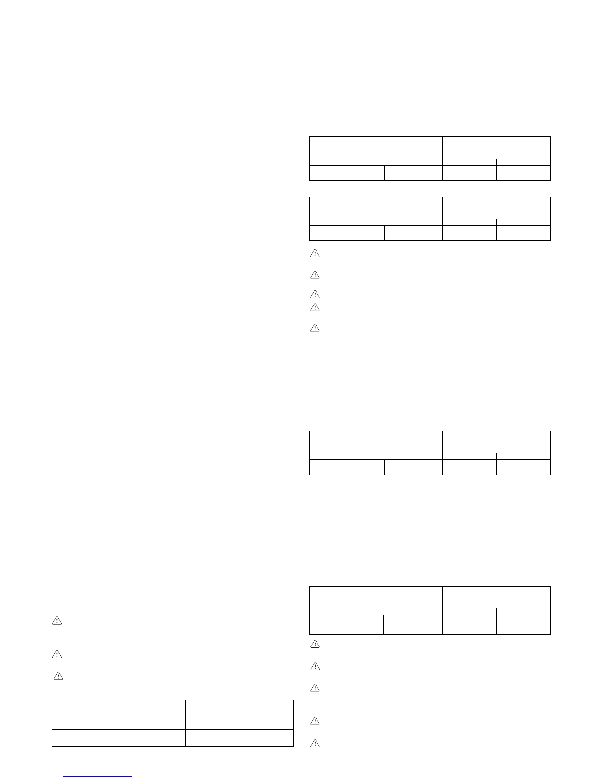
max length fumes
outlet duct ø 80 (m)
0,5 0,854230 B.S.I.
pressure drop
for each bend (m)
45°
90°
INSTALLATION “SEALED” (TYPE C)
Boiler is a C-type appliance (sealed chamber) and must be safely
connected to fume exhaustion duct and burning air suction duct,
both getting outside; appliance cannot operate without these ducts.
Concentric outlets (ø 60-100)
Concentric ducts may be placed in the most suitable direction for
installation requirements but special care must be taken as regards
the external temperature and the length of the duct.
Rectilinear length means without bends, outlet ends and
connections.
Horizontal
max. linear length
concentric duct ø 60-100 (m)
pressure drop
for each bend (m)
45° 90°
7,8030 B.S.I. 0,5 0,85
Vertical
max. linear length
concentric duct ø 60-100 (m)
pressure drop
for each bend (m)
45°
90°
8,8030 B.S.I. 0,5 0,85
Rectilinear length means without bends, outlet ends and
connections.
The fumes outlet duct must slope by 1% towards the condensate collector.
Uninsulated fumes outlets are potential hazards.
The boiler automatically adapts ventilation according to the type
of installation and the length of the duct.
Do not obstruct or narrow the comburent air inlet duct in any
way.
To install follow the instructions supplied with the kit.
Concentric outlets (ø 80-125 mm)
For this installation it is necessary to install the suitable adaptor kit.
Ducts may be placed in the most suitable direction for installation
requirements. For the installation process, follow the instructions
supplied with the kit for the specific accessory for condensation
boilers.
max. linear length
concentric duct ø 80-125 (m)
pressure drop
for each bend (m)
45°
90°
1830 B.S.I. 0,5 0,85
Twin outlets (ø 80)
The split duct can be aimed in the most suitable direction for
installation needs.
The combustion-supporting air intake duct must be connected to
the entrance after having removed the closing cap, attached with
three screws, and having attached a suitable adaptor.
The fumes outlet duct must be connected to the fumes outlet after
having installed a suitable adaptor.
For the installation process, follow the instructions supplied with
the kit for the specific accessory for condensation boilers.
max. length
twin duct (ø 80) (m)
30 B.S.I.
pressure drop
for each bend (m)
45° 90°
35 + 35
0,5 0,85
The fumes outlet duct must slope by 1% towards the condensate collector.
The boiler automatically adapts ventilation according to the
type of installation and the length of the duct. Do not obstruct
or narrow the comburent air inlet duct in any way.
For an indication of the maximum lengths of every single pipe,
refer to the graphs.
Using longer ducts causes a loss in the power of the boiler.
9 - FUMES EXHAUSTION AND BURNING AIR SUCTION
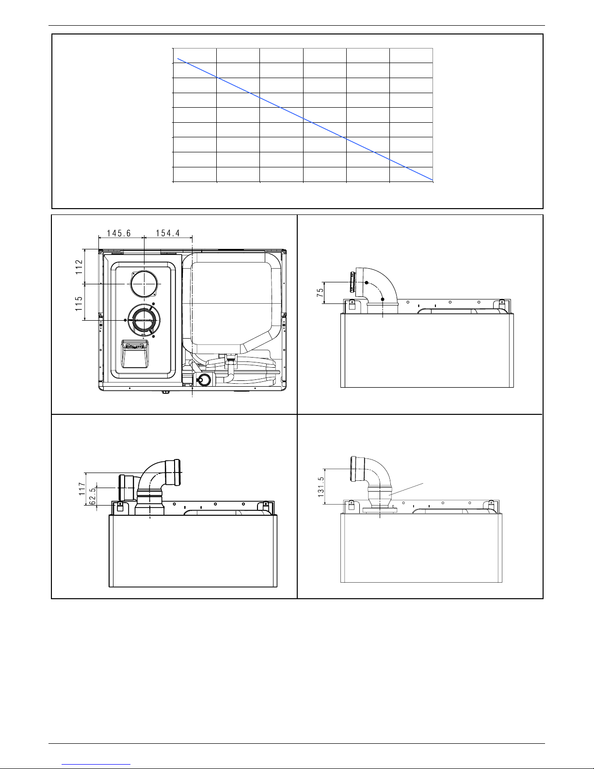
EXHAUSTION CONFIGURATIONS (fig. 8)
Boiler is homologated for the following exhaustion configurations:
B23P-B53P Suction in room and discharge outside
C13 Concentric wall exhaustion. Pipes can separately start
from boiler, but outlets must be concentric or close
enough to be subject to similar wind conditions (within
50 cm).
C23 Concentric exhaustion in common chimney (suction
and exhaustion in the same chimney).
C33 Concentric roof exhaustion. Outlets like C13.
C43 Exhaustion and suction in common separate
chimneys, but subject to similar wind conditions.
C53 Wall or roof separate exhaustion and suction in
different pressure areas. Exhaustion and suction must
never be located on opposite walls.
C63 Exhaustion and suction with separately certified and
sold pipes (1856/1).
C83 Single or common chimney exhaustion and wall
suction.
Refer to regulations in force for exhaustion of combustion products.
Boiler is provided for without fume exhaustion/air suction kit, since
forced draught sealed chamber accessories can be used, as they
better adapt to installation characteristics.
For fume extraction and burning air restoration in boiler, use original
pipes or other EC-certified pipes with equivalent characteristics; check
connection is correct as shown on instructions fume accessories
provided for with. More appliances can be connected to a single
chimney, provided that all appliances are sealed chamber type.
“FORCED OPEN” INSTALLATION
(TYPE B23P-B53P, intake inside and outlet outside)
Fumes outlet duct ø 80 mm
The fumes outlet duct can be aimed in the most suitable direction
for installation needs.
To install follow the instructions supplied with the kit.
In this configuration, the boiler is connected to the ø 80 mm fumes
outlet duct by means of a ø 60-80 mm adaptor.
In this case, the combustion supporting air is taken from the
room in which the boiler is installed, which must be a suitable
and ventilated technical room.
Non-insulated fumes outlet ducts are potential sources of
danger.
Provision must be made for a 1% slope of the fumes outlet duct
towards the boiler.
DHW system emptying (fig. 7)
The hot water system must be emptied every time there is risk of
freezing by:
- turning off the stopcock at the mains
- unscrew the cap on the hose adapter (G)
- connect a plastic hose to the hose adapter of the storage boiler
drain valve (G)
- open the valve drain device
- turning on all the hot and cold taps
- emptying out the lowest parts of the system.
ATTENTION
The collector must be connected, by means of a rubber pipe, to a
suitable collection and evacuation system in the storm water outlet
and in compliance with current regulations. The external diameter
of the collector is 20 mm: we therefore suggest using an Ø18-19
mm pipe, to be closed with a suitable clamp (not supplied). The
manufacturer is not responsible for any damage caused by the
lack of a collection system.
Page 7
77
77
7
ENGLISHENGLISH
ENGLISHENGLISH
ENGLISH
CONCENTRIC DUCT
FOR FUMES OUTLET/AIR INTAKE
SPLIT DUCTS
FOR FUMES OUTLET/AIR INTAKE
FUMES DUCT FOR INTAKE
IN ENVIRONMENTS
adaptor
Ø 60-80
LENGTH OF THE INTAKE DUCT (m)
EXHAUSTION LENGHT (m)
0
10
20
30
40
50
60
70
80
90
0 102030405060
910
11 12
Page 8

88
88
8
EXCLUSIEXCLUSI
EXCLUSIEXCLUSI
EXCLUSI
VE BOILER GREEN 30 BVE BOILER GREEN 30 B
VE BOILER GREEN 30 BVE BOILER GREEN 30 B
VE BOILER GREEN 30 B
.S.S
.S.S
.S
.I.I
.I.I
.I
..
..
.
CH: Nominal thermal flow rate (Hi) kW 30,00
kcal/h 25.800
Nominal thermal power (80°-60°) kW 29,01
kcal/h 24.949
Nominal thermal power (50°-30°) kW 31,41
kcal/h 27.013
Reduced thermal flow rate (Hi) kW 6,00
kcal/h 5.160
Reduced thermal power (80°-60°) kW 5,73
kcal/h 4.928
Reduced thermal power (50°-30°) kW 6,31
kcal/h 5.428
DHW: Nominal thermal flow rate kW 30,00
kcal/h 25.800
Maximum thermal power (*) kW 30,00
kcal/h 25.800
Reduced thermal flow rate kW 6,00
kcal/h 5.160
Minimum thermal power (*) kW 6,00
kcal/h 5.160
Working efficiency Pn max - Pn min (80°-60°) % 96,7 - 95,5
Working efficiency 30% (47° return) % 102,0
Combustion efficiency % 96,9
Working efficiency Pn max - Pn min (50°-30°) % 104,7 - 105,2
Working efficiency 30% (30° return) % 108,1
Category II2H3P
Electric power W 150
Supply voltage V - Hz 230 - 50
Protection level IP X5D
Chimney and skirt losses with burner off % 0,10 - 0,80
CH operation
Maximum pressure - temperature bar - °C 3 - 90
Minimum pressure for standard working/operating bar 0,25 ÷ 0,45
Selection field of CH water temperature °C 20 - 80
Pump: maximum head available for system mbar 300
capacity l/h 1000
Membrane expansion tank l 10
Expansion vessel pre-charge (CH) bar 1
DHW operation
Maximum pressure bar 8
Minimum pressure bar 0,2
Specific flow rate as per EN625 l/min 20,2
Selection field of DHW temperature °C 35 - 60
Flow regulator l/min 15
Boiler l60
Gas pressure
Natural gas pressure (G20) mbar 20
LPG pressure (G31) mbar 37
Hydraulic connections
CH input-output Ø 3/4”
DHW input-output Ø 1/2”
Gas input Ø 3/4”
Boiler dimensions and weight
Height mm 940
Width mm 600
Depth mm 450
Weight kg 68
Flow rates (G20)
Air capacity Nm3/h 36,234
Fumes capacity Nm3/h 39,143
Mass flow (max) gr/s 13,13
Mass flow (min) gr/s 2,72
Fan performance
Fan residual head, pipes 0,5 + bend 90° (intake+discharge) Pa 142
Fume exhaustion and air suction concentric pipe
Diameter mm 60 - 100
Max lenght m 7,80
Loss for a 90°/45° bend m 0,85/0,50
Hole in wall (diameter) mm 105
Fume exhaustion and air suction concentric pipe
Diameter mm 80 - 125
Max lenght m 18**
Loss for a 90°/45° bend m 0,85/0,50
Fume exhaustion and air suction separated pipe
Diameter mm 80
Max lenght m 35 + 35
Loss for a 90°/45° bend m 0,85/0,5
Forced open installation (B23P/B53P)
Diameter mm 80
Max lenght m42
Loss for a 90°/45° bend m 0,85/0,5
Exclusive Boiler
Green 30 B.S.I.
10 - 10 -
10 - 10 -
10 -
TT
TT
TECHNICAL DATA
Page 9

99
99
9
ENGLISHENGLISH
ENGLISHENGLISH
ENGLISH
LPG
propan (G31)
PARAMETERS
Methan
(G20)
Lower Wobbe index
(at 15°C-1013 mbar ) . . . ...........MJ/m3S 45,67 70,69
Lower heat value . . . ...................MJ/m3S 34,02 88
Supply nominal pressure ...............mbar (mm H
2
O) 20 (203,9) 37 (377,3)
Supply minimum pressure...............mbar (mm H2O) 10 (102,0)
Number of main burner nozzles . . . . . ............. n° 1 1
Burner diameter ....................... Ø mm 70 70
Gas diaphragm ....................... Ø mm 6,7 4,7
Burner length ......................... mm 147 147
CH maximum gas capacity . . . . . . . ............Sm
3
/h 3,17
...................kg/h 2,33
DHW maximum gas capacity . . . . . . ............Sm
3
/h 3,17
..................kg/h 2,33
CH minimum gas capacity . . . . . . . ............Sm3/h 0,63
..................kg/h 0,47
DHW minimum gas capacity . . . . . . ............Sm
3
/h 0,63
..................kg/h 0,47
Numbers of fan revolutions at slow start . ............revs/min 3.700 3.700
Maximum number of fan revolutions . . . ............revs/min 5.600 5.600
Minimun number of fan revoluitions . . . ............revs/min 1.400 1.400
WATER TANK DESCRIPTION
Water tank type Inox steel
Water tank disposition Vertical
Exchanger disposition Vertical
DHW contents l60
Coil contents l 3,87
Exchange surface m
2
0,707
Selection field of DHW temperature °C 35 - 60
Flow regulator l/min 15
Hot water quantity drawn in 10’ with ∆t 30 °C l 202
Water tank maximum pressure bar 8
NOx 5 class
Emission values at maximum and minimum of gas G20***
Maximum CO s.a. lower than p.p.m. 230
CO2 % 9,0
NOx s.a. lower than p.p.m. 60
∆t fumes °C 6 0
Minimum CO s.a. lower than p.p.m. 40
CO2 % 9,0
NOx s.a. lower than p.p.m. 40
∆t fumes °C 3 4
* Average value among various sanitary running conditions.
** Estimated with one 90° bend, 17 extensions of 1 meter and a horizontal exhaust of 1 meter.
*** Tested with ø 60-100 concentric, lenght 0,85m, water temperature 80-60°C.
11 - MULTIGAS TABLE
Page 10

1010
1010
10
EXCLUSIEXCLUSI
EXCLUSIEXCLUSI
EXCLUSI
VE BOILER GREEN 30 BVE BOILER GREEN 30 B
VE BOILER GREEN 30 BVE BOILER GREEN 30 B
VE BOILER GREEN 30 B
.S.S
.S.S
.S
.I.I
.I.I
.I
..
..
.
Description of commands
Heating water temperature selector: sets the heating water
temperature.
Domestic hot water temperature selector: sets the domestic
hot water temperature storaged in the water tank.
Setting parameters selector: using in calibration and
programmation phase.
Function key:
- ON the boiler is electrically powered and waiting for
operating requests (
- )
- OFF the boiler is electrically powered but will not respond
to operating requests
- RESET resets the boiler following a fault
Operating mode button:
button allows to choose the
desired operating mode: (winter) or (summer).
Info button: shows a sequence of information concerning the
operating status of the machine.
Filling button: pushing it, the boiler automatically fills the system
until the pressure reaches 1 to 1.5 bar.
Description of display symbols
14
13
graduated heating water temperature scale with
heating function symbol
graduated domestic hot water temperature scale with
domestic hot water function symbol
domestic hot water function symbol
fault symbol (for details, please see page 14)
reset symbol (for details, please see page 14)
pressure value
external sensor connection
heating/domestic hot water temperature
or
fault symbol (e.g. 10 - no flame)
function selector (turned to the chosen operating mode:
winter or summer)
burner operating symbol
anti-freeze function active symbol
system filling function symbol
fill symbol
Domestic
hot water
temperature
selector
Operating
mode button
ON-OFF-RESET
function selector
Filling
button
Heating water
circuit temperature
selector
INFO
button
Setting
parameters
selector
12 - START-UP AND OPERATION
The boiler produces heating and domestic hot water.
The control panel (fig. 13) contains the main boiler control and
management functions.
Page 11

1111
1111
11
ENGLISHENGLISH
ENGLISHENGLISH
ENGLISH
Switching on
Switch on the boiler as follows:
- access the gas tap through the slots in the cover located in the
lower part of the boiler
- open the gas tap by turning it anti-clockwise (fig. 15)
- power the boiler.
Each time the power supply is switched on the boiler carries out
an automatic venting cycle that lasts about 2 minutes. The display
reads “SF” (fig. 16) and the “function selectors”
light up in
sequence. Press the
button to interrupt the automatic
venting cycle.
If the check is concluded correctly, once the automatic venting
cycle has been completed the boiler is ready to work.
The boiler turns on in the status it was in before it was switched
off: if the boiler was in the winter mode when it was switched
off, it will turn on again in the winter mode. If it was in the OFF
mode, the display will show two segments in the central area
(fig. 17). Press the button to enable operation.
Choose the desired operating mode by pressing
button,
until the symbol moves to:
WINTER
SUMMER
WINTER function (fig. 18)
With the selector in this position, the boiler provides hot water for
the heating and provides water to the water tank to allow domestic
hot water preparation. Function S.A.R.A is enabled in this position
(see chapter “Boiler functions”).
SUMMER function (fig. 19)
With the selector in this position, the boiler provides water to the
water tank with a temperature stabiliser to allow domestic hot water
preparation.
15
open
position
16
17
18
Adjusting heating water temperature
Turning the selector A (fig. 20), after having positioned the selector
mode on winter
, it is possible to regulate the heating water
temperature.
Turn clockwise to increase the temperature and anticlockwise to
decrease. The bar segments light up (every 5°C) as the temperature is increased. The selected temperature value appears on the
display.
Adjusting heating water temperature with an external sensor
connected
When an external probe is connected, the value of the delivery
temperature is automatically chosen by the system which rapidly
adjusts ambient temperature to the changes in external temperature. Just the central segment of the bar is illuminated (fig. 21).
To increase or decrease the temperature with respect to the value
automatically calculated by the electronic board, turn the heating
water selector clockwise to increase and anticlockwise to decrease.
The bar segments light up (at every comfort level), correction
tolerance lies between - 5 and + 5 comfort levels (fig. 21). When
choosing the level of comfort, the digit area of the display shows
the required level of comfort while the bar shows the matching
segment (fig. 22).
Adjusting domestic hot water temperature
To adjust domestic hot water temperature storaged in the water
tank, turn switch B (fig. 23) clockwise to increase and anticlockwise
to decrease. The bar segments light up (every 3°C) as the temperature is increased.
The selected temperature value appears on the display.
When choosing the temperature, both for heating and domestic
hot water, the display shows the value being selected. About 4
seconds after the selection has been made, the modification is
memorised and the display returns to the delivery temperature
read by the probe.
19
A
20
21
22
°C
+ 4/5
+ 3
+ 2
+ 1
0
- 1
- 2
- 3
- 4/5
Page 12

1212
1212
12
EXCLUSIEXCLUSI
EXCLUSIEXCLUSI
EXCLUSI
VE BOILER GREEN 30 BVE BOILER GREEN 30 B
VE BOILER GREEN 30 BVE BOILER GREEN 30 B
VE BOILER GREEN 30 B
.S.S
.S.S
.S
.I.I
.I.I
.I
..
..
.
Working the boiler
Adjust the ambient thermostat to the required temperature (approx.
20 °C). If there is a demand for heating water, the boiler starts
and the
symbol is shown on the display (fig. 24). The boiler will
remain working until the set temperatures are reached, after which
it will go on stand-by. In the event of ignition or operating faults,
the boiler will perform a “safety stop”.
The flame symbol
will go out and the fault code and will
be displayed (fig. 25). For a description of faults and how to reset
them, consult chapter “Troubleshooting”.
Switching off
Switching off for short periods
For brief absences press the
button to switch off the boiler. The
display will show two segments in the central area (fig. 17). When
the boiler remains powered with the gas tap open, it is protected
by the following systems:
- anti-freeze (fig. 26): when the temperature of the water in the
boiler falls below safety values, the circulator and the burner
work at minimum power to increase the water temperature to a
safe value (35 °C). The
symbol lights up on the display.
- circulator anti-block: one operating cycle is performed every
24 hours.
Switching off for long periods
For prolonged absences press the
button to switch off the boiler
(fig. 17). The display will show two segments in the central area.
Turn the main switch to “off”.
Turn off the gas tap under the boiler by turning it clockwise (fig. 27).
In this case, the anti-freeze and anti-block systems are disabled.
Empty the water circuit or suitably protect it with a good make
of anti-freeze. Drain the domestic hot water circuit.
23
B
tap
closed
26
27
Boiler functions
Semi-automatic filling
The boiler features a semi-automatic filling device which turns on
by pressing the button when the corresponding symbol is
shown on the display (fig. 28).
If this condition occurs it means that the system is incorrectly
pressurised though the boiler will continue to work regularly.
Press the circuit filling button
to start-up the filling sequence.
Press the circuit filling button
a second time to interrupt the
filling sequence. During filling, the drops of the circuit filling
symbol
and the growing pressure value appear on the
display in a cascade sequence (fig. 29).
After filling, the
symbol is displayed for a few moments and then
turns off.
Note
During filling, the boiler does not perform other functions. For
example, if there is a request for domestic hot water, the boiler is
unable to provide it until filling has finished.
Note
If circuit pressure reaches 0.6 bar, the pressure value flashes on
the display (fig. 30a); if it falls below a minimum safety value (0.3
bar), fault code 41 appears on the display (fig. 30b) for a certain
time, following which, if the fault persists, fault code 40 is displayed
(see chapter on “Troubleshooting”).
In the event of fault 40, press
to reset and then to start filling
the circuit. After correcting fault 40, the boiler runs an automatic
vent cycle lasting about 2 minutes; the display reads “SF” (fig.
31) and the “function selectors”
light up in sequence. Press
the
button to interrupt the automatic venting cycle. If you
have to fill the system several times, contact the Technical Service
Centre to check whether the heating circuit is watertight (see if
there are any leaks).
28
29
24
25
30a
30b
31
Page 13

1313
1313
13
ENGLISHENGLISH
ENGLISHENGLISH
ENGLISH
Information
Press , the display turns off and just the word InFO appears (fig.
32). Press the button
to view operating information. Press the
button again to move on to the next piece of information. If the
button is not pressed, the system automatically exits the function.
Info list:
Info 0 shows the word InFO (fig. 32)
Info 1 only with the external probe connected, displays external
temperature (e.g. 12 °C) (fig. 33).
The values shown on the display range between - 30 °C
and 35 °C.
Beyond these values the display shows “- -”
Info 2 shows circuit pressure (fig. 34)
36
37
35
34
33
32
Info 3 shows the set heating temperature (fig. 35)
Info 4 shows the set domestic hot water temperature (fig. 36)
Info 5 displays the set heating temperature, in reference to the
second circuit, only if it is connected.
S.A.R.A. function
If the “winter” mode is selected, the S.A.R.A. (Automatic Ambient
Adjustment System) function can be activated.
Turning the heating water temperature selector to a temperature
ranging between 55 and 65 °C the S.A.R.A. self-adjustment system
activates: depending on the temperature set on the ambient thermostat
and the time taken to reach it, the boiler automatically adjusts the
heating water temperature to reduce operating times, thereby
increasing operating comfort and energy saving.
It is possible to display information, which may be useful for the
Technical Assistance Centre, by pressing the button for 10
seconds: the code “INF2” appears on the display.
INF2
Step Description Display Display
2 digits 4 digits
1 Input probe temperature xx 01 ° C
2 Return probe temperature xx 02 ° C
3 First water tank probe temperature (*) xx 03 ° C
4 Not used in this model xx Cond ° C
5 Fumes probe temperature xx (**) 05
6 Second heating system probe temperature xx 06 ° C
7 Not used in this model xx 07
8 Ventilator speed /100 xx FAN
9 Not used in this model xx 09
10 Not used in this model xx 10
11 Exchanger cleaning counter status bH xxxx
12-19 Historic alarm codes xx HIS0-HIS7
INF2 list
Note (*): if the water tank probe is faulty or disconnected, in the place of the value “- -” is displayed.
(**): if the display also shows the dot (.), the temperature of the fumes probe is 100+displayed value
Page 14
1414
1414
14
EXCLUSIEXCLUSI
EXCLUSIEXCLUSI
EXCLUSI
VE BOILER GREEN 30 BVE BOILER GREEN 30 B
VE BOILER GREEN 30 BVE BOILER GREEN 30 B
VE BOILER GREEN 30 B
.S.S
.S.S
.S
.I.I
.I.I
.I
..
..
.
Troubleshooting
When a fault appears on the display, the flame symbol goes out,
a flashing code is shown and the two symbols and
appear either together or separately.
For a description of the faults, consult the following table.
(D) Permanent
(T) Temporary. In this operating status the boiler attempts to eliminate the fault on its own
(°) See NOTE in the next page.
(*) If these two errors occur, check the pressure indicated on the water gauge. If the pressure is insufficient (< 0,4 bar, red area), proceed with the filling
operations described in the chapter “Filling and emptying the systems”.
If the system’s pressure is sufficient (> 0,6 bar, blue area) the malfunction is caused by a lack of water circulation. Contact the Technical Assistance.
(-) Call the technical assistance service
FAULT Alarm Symbol Symbol
ID
FLAME FAILURE BLOCK (D) 10 YES NO
PARASITE FLAME (T) 11 NO YES
RE-ATTEMPT IN PROGRESS (T) 12 NO NO
MINIMUM GAS INPUT PRESSURE (T) 13 NO YES
MINIMUM GAS INPUT PRESSURE (D) 14 YES NO
FLAME PRESENT IN STAND-BY FOR NO REASON (D) 15 YES YES
LIMIT THERMOSTAT (D) 20 YES NO
SHORT CIRCUIT FUMES PROBE (D) 21 YES YES
MAXIMUM TEMPERATURE FUMES PROBE (D) 22 YES NO
MAXIMUM TEMPERATURE INPUT PROBE (D) 24 YES NO
MAXIMUM TEMPERATURE INPUT PROBE (T) 25 NO YES
MAXIMUM TEMPERATURE RETURN PROBE (D) 26 YES NO
MAXIMUM TEMPERATURE RETURN PROBE (T) 27 NO YES
RETURN-INPUT PROBE DIFFERENTIAL (D) 28 YES YES
FUMES PROBE OVERTEMPERATURE (D) 29 YES YES
FUMES OUTLET OR AIR PRESSURE SWITCH (cycle start) (D) 30 YES NO
FUMES OUTLET OR AIR PRESSURE SWITCH (cycle start) (T) 31 NO YES
VENTILATOR IN CYCLE (low number of revolutions) (D) 33 YES YES
VENTILATOR (cycle start) (D) 34 YES NO
VENTILATOR (cycle end) (T) 35 NO YES
FUMES OUTLET OR AIR PRESSURE SWITCH (in cycle) (T) 36 NO YES
VENTILATOR IN CYCLE (high number of revolutions) (D) 37 YES YES
FUMES OUTLET OR AIR PRESSURE SWITCH (in cycle) (D) 38 YES YES
INSUFFICIENT SYSTEM PRESSURE (D*) 40 YES NO
INSUFFICIENT SYSTEM PRESSURE (T*) 41 NO YES
WATER PRESSURE TRANSDUCER (D) 42 YES YES
ELECTRONIC BOARD (D) 50-59 YES YES
SANITARY PROBE 1 (T°) 60 NO YES
SHORT CIRCUIT/OPEN PRIMARY PROBE (D) 70 YES YES
MAXIMUM TEMPERATURE INPUT PROBE (T) 71 NO NO
SHORT CIRCUIT/OPEN RETURN PROBE (D) 72 YES YES
LOW TEMPERATURE THERMOSTAT (T) 77 NO YES
INPUT/RETURN DIFFERENTIAL (T) 78 NO YES
INPUT/RETURN DIFFERENTIAL (D) 79 YES NO
SYSTEM ANOMALY (D) 80 YES YES
SYSTEM ANOMALY (T) 81 NO YES
SYSTEM ANOMALY (D) 82 YES YES
SYSTEM ANOMALY (T) 83 NO YES
CLEAN PRIMARY EXCHANGER (-) 91 NO YES
CONDENSATE OR CONDENSATE SENSOR (D) 92 YES NO
CONDENSATE OR CONDENSATE SENSOR (T) 93 NO YES
CONDENSATE SENSOR OR OPEN CIRCUIT (T) 95 NO YES
Page 15

1515
1515
15
ENGLISHENGLISH
ENGLISHENGLISH
ENGLISH
Resetting faults
Wait for about 10 seconds before resetting operating conditions.
Then proceed as follows:
1) Viewing just the
symbol
If disappears, it means that an operating fault has been
discovered which the boiler is attempting to solve on its own
(temporary stoppage). If the boiler does not resume normal
operation, two things may happen:
case A (fig. 38)
disappears, the symbol and a different alarm code
appear. In this case, proceed as described in point 2.
case B (fig. 39)
and a different alarm code are displayed together with .
In this case, proceed as described in point 3.
case C - alarm 91 (Call the technical assistance service)
The boiler has a self-diagnosis system which, on the basis of the
hours totalised in particular operating conditions, signals the need
for maintenance or cleaning of the primary exchanger (alarm code
91). After cleaning using the kit supplied as an accessory, reset
the hour counter as follows:
- disconnect the mains power supply
- remove the screws and hooks securing the electrical cover
- remove connector J13 (see wiring diagram)
- power the boiler and wait for alarm 13 to appear on the display
- disconnect the power supply and reconnect connector J13
- put back the electrical cover and restart the boiler
N.B.: perform the counter reset procedure every time the primary
exchanger is thoroughly cleaned or replaced.
2) Viewing just the
symbol (fig. 40)
Press the
button to reset the appliance. If the boiler starts the
ignition phase and resumes normal operation, it may have
stopped by accident.
If these stoppages should continue, contact the Technical
Assistance Centre.
3) Viewing the
and symbols (fig. 41)
Contact the Technical Assistance Centre.
Note
Fault in domestic hot water circuit sensor - 60: the boiler works
regularly but does not ensure the stability of the hot water
temperature which, however, is delivered at a temperature of
approximately 50°C. The fault code is only displayed in standby.
“temporary fault”
“permanent fault”
“temporary fault”
“permanent fault”
This boiler incorporates a new generation of electronic boards that, by
setting/modifying operating parameters, allow the boiler to be
personalised to satisfy various system and/or user requirements. The
programmable parameters are shown in the table on the next page.
The parameters must be programmed with the boiler in the
OFF position. To do this, press the
button until the display
shows “- -” (fig. 42).
During parameter modification operations, the “select
functions” button acts as an ENTER (confirm) button, the
button acts as an ESCAPE (escape) button. If no confirmation
is given within 10 seconds, the value is discarded and returns
to the previously set one.
Setting the password
Press and hold down the select functions button and the
button
together for about 10 seconds. The display will look like fig. 43.
Enter the password for accessing the parameter modifications
function by turning the domestic hot water temperature selector to
obtain the required value. The password for accessing the
parameter programming function is located on the back side of
the control panel. Confirm by pressing ENTER.
Modifying parameters
Turn the domestic hot water temperature selector (fig. 44) to
sequentially scroll the two-figure codes of the parameters indicated
in the table. After identifying the parameter you wish to modify,
proceed as follows:
- press ENTER to access the parameter modification function. When
ENTER is pressed, the previously set value starts flashing (fig. 45)
- turn the domestic hot water temperature selector to change the value
- press ENTER to confirm the new value. The digits stop flashing
- press ESCAPE to exit.
The boiler returns to the “- -” (OFF) status.
To reset, press the
button (fig. 42).
42
43
44
45
ENTER
ESCAPE
parameter
number
parameter
value
13 - PROGRAMMING PARAMETERS
38
39
40
41
Page 16

1616
1616
16
EXCLUSIEXCLUSI
EXCLUSIEXCLUSI
EXCLUSI
VE BOILER GREEN 30 BVE BOILER GREEN 30 B
VE BOILER GREEN 30 BVE BOILER GREEN 30 B
VE BOILER GREEN 30 B
.S.S
.S.S
.S
.I.I
.I.I
.I
..
..
.
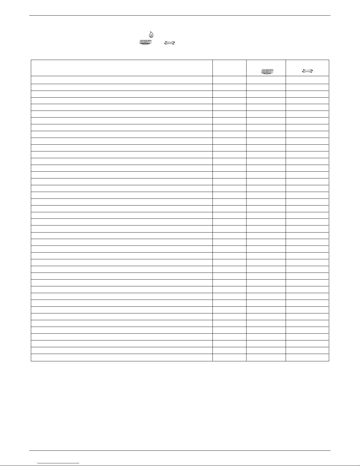
Programmable parameters
* Power not available at the moment
** The value is expressed on the display in revs/min/100 (example 3.600 = 36)
N° DESCRIPTION PARAMETERS UNIT OF MIN MAX DEFAULT PARAMETERS
PAR. MEASURE (setted in (setted by techn.
factory) assist. centre)
1 GAS TYPE 1 Methane 1
2 LPG
3 Methane France
2 BOILER POWER 10*-16-20*-26-30-34-50*-70* 30
3 INSULATION LEVEL OF BUILDING min 5 2 0 5
10 DHW MODE 0 (OFF) 5
1 (Instantaneous)
2 (Mini-tank)
3 (External water-tank with thermostat)
4 (External water-tank with sensor)
5 (Integrated water tank)
11 THIS PARAMETER IS NOT USED ON THIS MODEL. DO NOT MODIFY 60
12 WATER TANK MAXIMUM SET-POINT ° C 40 80 60
13 DELIVERY TERMPERATURE EXT. WATER TANK ° C 50 8 5 80
14 DELTA EXTERNAL WATER TANK (ON) ° C 0 1 0 5
20 HEATING MODE 0 (OFF) 1
1 (ON)
2 (not used)
3 (CONNECT AP)
4 (not used)
5 (not used)
6 (CONNECT AT/BT)
21 HEATING CIRCUIT MAXIMUM SET-POINT ° C 40 80 80
22 MINIMUM HEATING SET POINT ° C 20 39 20
23 MAXIMUM HEATING VENTILATOR SPEED revs/min 36 (3.600**) MAX
24 MINIMUM HEATING VENTILATOR SPEED revs/min 36 (3.600**) MIN
25 DIFFERENTIAL HEATING POSITIVE ° C 2 1 0 6
26 DIFFERENTIAL HEATING NEGATIVE ° C 2 1 0 6
28 MAX HEATING POWER REDUCTION TIMER min 0 20 1 5
29 FORCED HEATING SHUT DOWN TIMER min 0 20 5
30 HEATING TIMER RESET FUNCTION - 0 (NO) 1 (YES) 0
31 MAXIMUM HEATING SET POINT 2CH (II circuit) ° C 40 8 0 80
32 MINIMUM HEATING SET POINT 2CH (II circuit) ° C 20 3 9 20
40 THIS PARAMETER IS NOT USED ON THIS MODEL. DO NOT MODIFY 1
41 THIS PARAMETER IS NOT USED ON THIS MODEL. DO NOT MODIFY 1
42 S.A.R.A. FUNCTION 0 (OFF) 1
1 (AUTO)
43 THIS PARAMETER IS NOT USED ON THIS MODEL. DO NOT MODIFY 1
44 THERMOREGULATION FUNCTION 0 (OFF) 1
1 (AUTO)
45 INCLINATION THERMOREGULATION CURVE (OTC) - 2,5 40 2 0
46 THERMOREGULATION FUNCTION 2CH 0 (OFF) 1
1 (AUTO)
47 INCLINATION THERMOREGULATION CURVE (OTC) 2CH - 2 ,5 4 0 2 0
48 THIS PARAMETER IS NOT USED ON THIS MODEL. DO NOT MODIFY 0
50 THIS PARAMETER IS NOT USED ON THIS MODEL. DO NOT MODIFY 1
51 HEAT REQUEST TYPE CH1 (I circuit) - 0 1 0
52 HEAT REQUEST TYPE CH2 (II circuit) - 0 1 0
61 THIS PARAMETER IS NOT USED ON THIS MODEL. DO NOT MODIFY 4
62 HEATING ANTIFREEZE FUNC. DELIVERY TEMP. (ON) °C 0 1 0 6
63 WATER TANK ANTIFREEZE FUNC. DELIV. TEMP. (ON) °C 0 1 0 6
65 EXTERNAL SENSOR REACTIVITY
0 (very fast) 255 (very slow)
255
85 SEMI-AUTOMATIC FILLING 0 (disabled) 1
1 (enabled)
86 AUTOMATIC FILLING PRESSURE (ON) bar 0.4 1.0 0.6
92 ENABLE POST-CIRCULATION FROM DHW TO HEATING 0 1 0
93 DURATION OF POST-CIRCULATION FROM DHW TO HEATING 1 255 5
94 PUMP IN CONTINUAL MODE CH1 (CIRCUIT 1) 0 1 0
95 PUMP IN CONTINUAL MODE CH2 (CIRCUIT 2) 0 1 0
G20 G31
30kW 56 56
G20 G31
30kW 14 14
Page 17

1717
1717
17
ENGLISHENGLISH
ENGLISHENGLISH
ENGLISH
Checking the connection with the external probe
After connecting the external probe to the boiler, use the INFO
function to check that the probe has been automatically recognised
by the temperature control card. Immediately after installation, the
PARAMETER AVAILABLE IN THE PROGRAMMING MODE
TYPE OF BUILDING 3 INSTALLATION AND CALIBRATION & SERVICE
MAXIMUM HEATING SET POINT 21 INSTALLATION
MINIMUM HEATING SET POINT 22 INSTALLATION
ENABLE THERMOREGULATION FUNCTION 44 INSTALLATION
OFFSET TEMPERATURE CURVE 45 INSTALLATION AND CALIBRATION & SERVICE
TYPE OF HEAT REQUEST 51 INSTALLATION
To access the programming mode, consult “Programming
parameters”.
PARAMETER 03. Type of building
In order to calculate delivery temperature, the temperature control
system does not directly use the external temperature value but
considers the heat insulation of the building: in well-lagged
buildings, external temperature variations affect the ambient
temperature less than they do in badly-lagged buildings. Use
parameter 3 to set the heat insulation level of the building
according to the following scheme:
value read by the probe may very well be higher then that measured
by a reference probe.
Enable and optimise the THERMOREGULATION function by
setting the following parameters:
New houses Old houses
Hollow bricks Solid bricks Stones
a19 14 128
b20 16 1511
c19 15 149
d18 12 105
types of building
a
b
c
d
PARAMETERS 21 and 22. Maximum and minimum delivery
temperature
These two parameters limit the delivery temperature automatically
produced by the TEMPERATURE CONTROL function.
PARAMETER 21 determines MAXIMUM DELIVERY
TEMPERATURE (MAXIMUM HEATING SET POINT) while
PARAMETER 22 determines MINIMUM DELIVERY
TEMPERATURE (MINIMUM HEATING SET POINT).
PARAMETER 45. Choosing the offset temperature curve (graph 1)
The offset heating curve maintains a theoretical ambient
temperature of 20°C at external temperatures ranging from +20°C
to -20°C. The choice of the curve depends on the rated minimum
external temperature (on the geographical area, therefore) and
the rated delivery temperature (on the type of system, therefore)
and must be carefully calculated by the fitter using the following
formula:
PARAMETER 44. Enable thermoregulation function
The connected external temperature probe combined with
PARAMETER 44 provides the following operating modes:
EXTERNAL PROBE CONNECTED and PARAMETER 44 = 0 (OFF)
in this case the TEMPERATURE CONTROL function is disabled
even though the external probe is connected. The temperature
read by the external probe can always be viewed by pressing the
INFO button. The TEMPERATURE CONTROL symbols are not
displayed.
EXTERNAL PROBE CONNECTED, PARAMETER 44 = 1 (ON) in
this case the TEMPERATURE CONTROL function is enabled. The
temperature read by the external probe and the TEMPERATURE
CONTROL symbols can be viewed by pressing the INFO button.
The TEMPERATURE CONTROL function cannot be enabled
unless the external probe has been fitted and connected. In
this case, PARAMETER 44 is ignored and has no effect on
boiler operation.
If, from your calculations, you obtain an intermediate value between
two curves, we suggest choosing the compensation curve closest
to the value obtained.
Example: if the value obtained from the calculations is 8, this is
between curve 7.5 and curve 10. In this case, choose the closest
curve, which is 7.5.
rated delivery T - 20
P. 45 = 10 x
20- rated min. external T
PARAMETER 51. Type of heat request
IF AN AMBIENT THERMOSTAT IS CONNECTED TO THE BOILER,
SET PARAMETER 51 = 0 (graph 2).
The ambient thermostat makes a heat request when its contact
closes, while it stops it when its contact opens. Though delivery
temperature is automatically calculated by the boiler, the user may
manually override it. By modifying HEATING on the user interface,
the HEATING SET POINT will no longer be available but just a
value that can be set from +5 to -5°C as required. Modifications to
this value do not directly change delivery temperature but affect
the calculation made to automatically determine its value by
modifying the reference temperature of the system (0 = 20°C).
IF A PROGRAMMABLE TIMER IS CONNECTED TO THE BOILER,
SET PARAMETER 51 = 1 (graph 3).
When the contact is closed, the heat request is made by the delivery
probe on the basis of the external temperature in order to maintain
the rated ambient temperature at the DAY level (20 °C). When the
contact opens, it does not stop the heat request but reduces (parallel
shift) the temperature curve to the NIGHT level (16 °C). Though
delivery temperature is automatically calculated by the boiler, the
user may manually override it.
By modifying HEATING on the user interface, the HEATING SET
POINT will no longer be available but just a value that can be set
from +5 to –5°C as required.
Modifications to this value do not directly change delivery
temperature but affect the calculation made to automatically
determine its value by modifying the reference temperature of the
system (0 = 20 °C for DAY level; 16 °C for NIGHT level).
14 - SETTING THE THERMOREGULATION
Page 18

1818
1818
18
EXCLUSIEXCLUSI
EXCLUSIEXCLUSI
EXCLUSI
VE BOILER GREEN 30 BVE BOILER GREEN 30 B
VE BOILER GREEN 30 BVE BOILER GREEN 30 B
VE BOILER GREEN 30 B
.S.S
.S.S
.S
.I.I
.I.I
.I
..
..
.
EXTERNAL TEMPERATURE (°C)
40
20
30
40
50
60
70
80
90
100
-20-15-10-505101520
32,5 25
17,5
10
2,5
P. 21
P. 22
20
30
27,5
22,535
37,5
40
5
7,5
15
12,5
THERMOREGULATION CURVES
P21 = MAXIMUM HEATING SET POINT
P22 = MINIMUM HEATING SET POINT
GRAPH 1
DELIVERY TEMPERATURE (°C)
EXTERNAL TEMPERATURE (°C)
TEMPERATURE CURVE CORRECTION
0 C
+ 5 C
- 5 C
10
20
30
40
50
60
70
80
90
-20-15-10-5051015202530
GRAPH 2
10
20
30
40
50
60
70
80
90
-20-15-10-505101520
Curva climatica GIORNO
Curva climatica NOTTE
PARALLEL NIGHT REDUCTION
DELIVERY TEMPERATURE (°C)
EXTERNAL TEMPERATURE (°C)
GRAPH 3
DAY
temperature curve
NIGHT
temperature curve
DELIVERY TEMPERATURE (°C)
CONNECT AT/BT
In case of using CONNECT AT/BT, accessory supplied on request,
the boiler gives the possibility to choose 2 thermoregulation curves:
- OTC 1 CH (parameter 45) for a direct system
- OTC 2 CH (parameter 47) for a mixed system.
Even in case of second circuit (2CH) the curve depends on the
external minimum project temperature (on the geographical area,
therefore) and on the delivey project temperature (on the type of
system, therefore); the installer must to put attention to calculate it
using the following formula:
Parameters 31 and 32 give the possibility to define the maximum
and the minimum central heating set-point of the second circuit.
To correct the curve in this configuration, please refer to the
instructions supplied with the accessory.
rated delivery T - 20
20- rated min. external T
P. 47 = 10 x
DHW operation
CH operation
Qn nominal capacity
Pn nominal power
IP protection level
P. min minimum pressure
Pmw DHW maximum pressure
Pms CH maximum pressure
T temperature
η working efficiency
D specific capacity
NOx NOx value class
15 - SERIAL NUMBER PLATE
Condensing boiler
Gas type
Gas
category
Page 19

1919
1919
19
ENGLISHENGLISH
ENGLISHENGLISH
ENGLISH
It is absolutely forbidden to set different gas types and/or boiler
powers from those indicated on the registration plate.
The manufacturer refuses any responsibility if the 2 parameters
are set at different values compared to those indicated on the
registration plate.
MAXIMUM VENTILATOR SPEED (P. HP)
- Select parameter HP
- Press the ENTER button, then modify the value of the parameter
by turning the sanitary water temperature selector. The maximum
speed of the fan is linked with the type of gas and the power of
the boiler, table 1
- Turn the sanitary water temperature selector in order to adjust
the set value
- Confirm the new value you have set by pressing ENTER.
The value indicated on the display is expressed in revs min/100
(example 3600 = 36).
The value set during this operation automatically modifies the
maximum value of parameter 23.
MINIMUM VENTILATOR SPEED (P. LP)
- Select parameter LP
- Press the ENTER button, then modify the value of the parameter
by turning the sanitary water temperature selector. The minimum
speed of the fan is linked with the type of gas and the power of the
boiler, table 2
- Turn the sanitary water temperature selector in order to adjust
the set value
- Confirm the new value you have set by pressing ENTER.
The value indicated on the display is expressed in revs min/100
(example 3600 = 36).
The value set during this operation automatically modifies the
maximum value of parameter 24.
VENTILATOR IGNITION SPEED (P. SP)
- Select parameter SP
- Press the ENTER button, then modify the value of the parameter
by turning the sanitary water temperature selector. The standard
slow start value is 3700 revs/min
- Confirm the new value you have set by pressing ENTER.
MAXIMUM POWER ADJUSTMENT (P. HH)
- Turn the boiler OFF
- Select the parameter HH and wait for the boiler to come on
- Check that the maximum CO
2
reading on the analyser (see
paragraph “Checking combustion parameters”, page 20)
corresponds with the values indicated in table 3.
If the CO
2
proves to comply with the values in the table, proceed to
adjust the next parameter (LL - adjusting the minimum), if different
modify the value by turning the
maximum power adjustment screw with a screwdriver (clockwise
to decrease) until you obtain a value contained in table 3.
The boiler has already been factory adjusted by the manufacturer.
If a new adjustment is required, for example, after extraordinary
maintenance, replacing the gas valve or converting from natural
gas to LPG, proceed as follows.
Maximum and minimum power, minimum and maximum
heating, must be adjusted in the indicated sequence by
qualified staff.
- Loosen the two fixing screws (A) and remove the shell (fig. 3)
- Lift up the panel and turn it forwards
- Loosen the pressure tap screw downline from the gas valve by
about two turns and connect the pressure gauge to it
CALIBRATION & SERVICE operations must be performed with
the boiler in the OFF position. To do this, press the
button
until the display shows “- -” (fig. 42).
During parameter modification operations, the “select
functions” button acts as an ENTER (confirm) button, the
button acts as an ESCAPE button. If no confirmation is given
within 10 seconds, the value is discarded and returns to the
previously set one.
Setting the password
Press and hold down the operating mode button and the
button
together for about 10 seconds. The display will look like fig. 43.
Enter the password for accessing the parameter modifications
function by turning the domestic hot water temperature selector to
the required value.
The password is located on the back side of the control panel.
Confirm by pressing ENTER.
Calibration phases
Turn the domestic hot water selector to sequentially scroll the
CALIBRATION & SERVICE phases:
- 1 gas type
- 2 boiler power (do not modify this parameter)
- 10 domestic hot water mode (do not modify this parameter)
- 3 insulation level of building (only if external sensor is
connected)
- 45 inclination of thermoregulation curve (OTC), only if external
sensor is connected)
- 47 inclination of thermoregulation curve 2CH (OTC), only if
external sensor is connected)
- HP maximum fan speed (do not modify this parameter)
- LP minimum fan speed (do not modify this parameter)
- SP ignition speed (do not modify this parameter)
- HH boiler at maximum power
- LL boiler at minimum power
- MM fan ignition speed (do not modify this parameter)
- 23 maximum heating adjustment possibility
- 24 minimum heating adjustment possibility.
The parameters 2 - 10 - HP - SP - LP - MM - 23 - 24 must be
modified, by professionally qualified personnel, only if
absolutely necessary. The manufacturer refuses any
responsibility in the case of incorrect setting of the
parameters.
GAS TYPE (P. 1)
Modify the set value as follows:
- press ENTER to access the parameter modification function.
When ENTER is pressed, the previously set value starts flashing
(fig. 45)
- turn the domestic hot water temperature selector to change the
value (1 MTN - 2 LPG)
- press ENTER to confirm the new value. The digits stop flashing.
BOILER POWER (P. 2)
To modify the boiler power:
- select parameter 02
- press the ENTER button to access the parameter value
modification function.
As the ENTER button is pressed, the digits flash, highlighting
the previously set value
- turn the sanitary water temperature selector in order to adjust
the value to the desired number: 30 (30 kW).
- confirm the new value you have set by pressing ENTER. The
digits stop flashing.
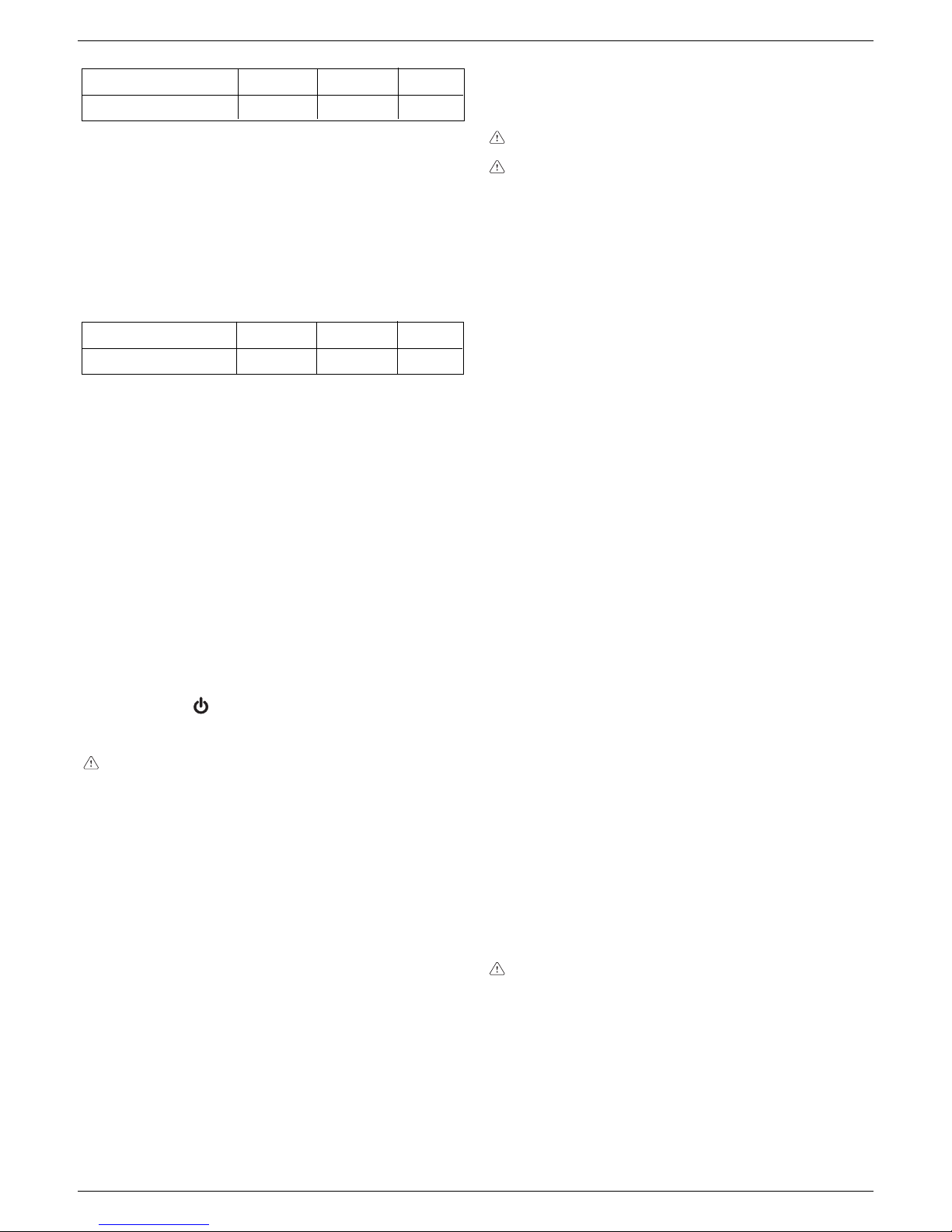
30 B.S.I. 56 56 revs/min
MAXIMUM NUMBER OF
FAN REVOLUTIONS
table 1
G31
G20
30 B.S.I. 14 14 revs/min
MINIMUM NUMBER OF
FAN REVOLUTIONS
table 2
G31
G20
Minimum power
adjusting screw
Maximum power
adjusting screw
46
16 - ADJUSTMENTS
Page 20
2020
2020
20
EXCLUSIEXCLUSI
EXCLUSIEXCLUSI
EXCLUSI
VE BOILER GREEN 30 BVE BOILER GREEN 30 B
VE BOILER GREEN 30 BVE BOILER GREEN 30 B
VE BOILER GREEN 30 B
.S.S
.S.S
.S
.I.I
.I.I
.I
..
..
.
MINIMUM POWER ADJUSTMENT (P. LL)
- Select the parameter LL (with the boiler still OFF) and wait for
the boiler to come on.
- Check that the minimum CO
2
reading on the analyser (see
paragraph “Checking combustion parameters”, page 20)
corresponds with the values indicated in table 4.
If the CO2 proves to be different from the values in the table, proceed
to adjust the parameter by turning the maximum power adjustment
screw after having unscrewed the protective cap (clockwise to
increase) until you obtain a value contained in table 4.
IGNITION SPEED (P. MM)
- Select parameter MM.
The boiler starts at the slow ignition speed.
- Turn the heating water selector to increase or decrease the fan
speed.
MAXIMUM HEATING ADJUSTMENT POSSIBILITY (P. 23)
- Select parameter 23
- Press the ENTER button to access the parameter value
modification function
- Turn the sanitary water selector to modify the maximum fan speed
- Confirm the value you have set by pressing ENTER.
MINIMUM HEATING ADJUSTMENT POSSIBILITY (P. 24)
- Select parameter 24
- Press the ENTER button to access the parameter value
modification function
- Turn the sanitary water selector to modify the minimum fan speed
- Confirm the value you have set by pressing ENTER.
Exit the CALIBRATION & SERVICE function by pressing ESCAPE.
The boiler returns to the “- -” (OFF) status.
To reset, press the
button.
- Disconnect the pressure gauge and tighten the pressure tap
screw.
After adjusting the gas valve, seal it with sealing wax.
After making adjustments:
- return the temperature set with the ambient thermostat to the
required position
- close the panel
- put back the shell.
30 B.S.I. CO2 max 9,0 10,0 %
DESCRIPTION
table 3
G31
G20
30 B.S.I. CO2 min 9,0 10,0 %
DESCRIPTION
table 4
G31
G20
To ensure the product remains in perfect working order, and to
comply with current legislation, systematically check the boiler at
regular intervals.
To analyse combustion, proceed as follows:
- access the CALIBRATION & SERVICE phase by setting the
password as indicated in chapter “Adjustments”
- insert the analyser probes in the designated positions on the air
chamber, after having removed screw A and cap B (fig. 49)
- make sure, in the HH and LL parameters, that the CO2 values
correspond with those indicated in the table. If the value displayed
is different, proceed to modify it as indicated in the chapter
“Adjustments”, in the sections for parameters HH and LL
- carry out the combustion analysis.
Subsequently:
- remove the analyser probes and close the combustion analysis
sockets with the designated screw
- close the instrument panel, reassemble the cover and boiler
shell, following the procedure described for dismantling it in
reverse order.
The fumes analysis probe must be fully inserted.
IMPORTANT: the function that switches off the boiler when water
temperature reaches a maximum of about 90 °C is still enabled
during the combustion analysis phase.
It is easy to convert from one gas family to another even after the
boiler has been installed. This operation must be performed by
professionally qualified staff. The boiler is designed to work with
natural gas. The product plate indicates which fuel it has been
fitted out to use.
It is possible to convert the boiler from one kind of gas to the other
using kits which can be supplied on request:
- natural gas to LPG conversion kit
- LPG to natural gas conversion kit.
To disassemble, proceed as follows:
- disconnect the boiler from the power supply and close the gas
tap
- remove the components to access to the internal parts of the
boiler (fig. 47)
- remove the gas ramp (A)
- remove the nozzle (B) contained inside the gas ramp and replace
it with the one contained in the kit
- remount the gas ramp
- remount components previously removed
- power the boiler and open the gas tap (with the boiler working,
check there are no leaks in the gas supply circuit).
Programme the “Gas type” parameter and adjust the boiler as
described in the “Adjustments” chapter.
The boiler may only be converted by qualified staff.
After conversion, adjust the boiler again as shown in the
relative paragraph and apply the new rating plate contained
in the kit.
After removing the flange it will be possible to inspect and clean
inside the water tank and check the condition of the magnesium
anode (fig. 48).
- Turn off the hot water system stopcock and empty the water tank
through the drainage device (page 5)
- Loosen the nut and extract the anode (1)
- Remove the nuts (2) blocking the external flange (3) and extract it
- Clean the inside surfaces and remove all the debris through the
opening
- Check the wear conditions of the magnesium anode (1), replace
if necessary
- Check that the gasket (4) is in good condition after extracting it
from the inside flange (5), replace if necessary.
Complete the work of cleaning, re-mount the components working
the other way round to above description.
17 - GAS CONVERSION
18 - CLEANING THE BOILER
19 - CHECKING COMBUSTION PARAMETERS
Page 21

2121
2121
21
FRANÇAIS
Les chaudières produites dans nos ateliers sont construites en
soignant particulièrement chaque composant de façon à protéger
l’utilisateur et l’installateur contre tout risque d’accident. Nous
recommandons donc au personnel qualifié de faire très attention aux
branchements électriques, après chaque intervention, surtout au
niveau de la partie mise à nue des conducteurs, qui ne doit jamais
sortir du bornier et en évitant autant que possible le contact avec les
parties sous-tension du conducteur.
Ce manuel fait partie intégrante de l’appareil: vérifiez s’il accompagne
toujours l’appareil, même en cas de cession à un autre propriétaire
ou utilisateur ou de transfert sur une autre installation. Si vous perdez
ou abîmez le manuel, veuillez en demander un autre au Service
Après-vente de votre région.
Le montage de la chaudière et toutes les autres opérations d’entretien
ou de dépannage ne doivent être confiées qu’à du personnel qualifié
conformément aux indications des lois en vigueur et de leur mise à
jour.
Les opérations d’entretien de la chaudière doivent être effectuées au
moins un fois par an après avoir été programmées à l’avance avec le
Service Après-vente.
Nous conseillons a l’installateur d’expliquer correctement à l’utilisateur
le fonctionnement de l’appareil et les mesures fondamentales de
sécurité
Cette chaudière ne doit être destinée qu’à l’usage pour lequel elle a
été construite. Toute responsabilité contractuelle et extracontractuelle
est exclue en cas de préjudices causés à des personnes, des animaux
ou des choses à la suite d’une erreur de montage, de réglage,
d’entretien ou d’un usage impropre.
Cet appareil sert à produire de l’eau chaude et doit être branché sur
une installation de chauffage et(ou) un réseau de distribution d’eau
chaude sanitaire, compatible à ses performances et à sa puissance.
Après avoir ôté l’emballage, vérifiez si son contenu est intègre et
complet. En cas de divergence, adressez vous au revendeur auquel
vous avez acheté l’appareil.
Nous vous recommandons d’effectuer l’entretien ordinaire après avoir
contrôlé le niveau d’usure de l’anode sacrificielle.
Le drainage de la soupape de sécurité de l’appareil doit être raccordé
sur un système de récolte et d’évacuation adéquat. Le constructeur
de l’appareil n’est pas responsable des préjudices éventuellement
causés par la soupape de sécurité.
En cas de panne et(ou) de mauvais fonctionnement de l’appareil,
arrêtez-le et ne tentez aucune réparation ou intervention directe.
Au moment de l’installation il est indispensable d’informer l’utilisateur
que:
- en cas de fuites d’eau, il doit fermer l’alimentation en eau et appeler
rapidement le Service Après-vente
- il doit vérifier régulièrement que l’icône
du tableau de commande
ne s’éclaire pas. Ce symbole indique que la pression de l’installation
hydraulique n’est pas correcte. En cas de besoin, charger l’installation
de la façon indiquée au chapitre “Fonctions de la chaudière”
- si la chaudière n’est pas utilisée pendant longtemps, nous conseillons de faire intervenir le service après-vente pour effectuer au
moins les opérations suivantes:
- placer l’interrupteur général de l’installation et l’interrupteur princi-
pal de l’appareil sur “éteint”
- refermer les robinets du combustible et de l’eau de l’installation
thermique et sanitaire
- vidanger l’installation thermique et sanitaire en cas de risque de
gel.
Raccorder le collecteur d’évacuation sur un système de récolte et
d’évacuation approprié (voir chapitre 5).
Par mesure de sécurité n’oubliez pas que:
il est tout à fait déconseillé de laisser les enfants ou les personnes
inaptes sans assistance utiliser seuls la chaudière
il est dangereux d’actionner les dispositifs électriques, comme les
interrupteurs, les électroménagers, etc.. si vous sentez une odeur de
combustible ou de combustion. En cas de fuites de gaz, aérez la
pièce en ouvrant complètement portes et fenêtres, fermez le robinet
général du gaz; faites intervenir rapidement le personnel qualifié du
service après-vente
ne touchez pas la chaudière si vous avez les pieds nus ou des
parties du corps mouillées ou humides
appuyez sur la touche
jusqu’à ce que l’afficheur montre “- -” et
débranchez la chaudière du réseau d’alimentation électrique en
plaçant l’interrupteur bipolaire se l’installation sur “éteint” avant
d’effectuer les opérations de nettoyage
il est interdit de modifier les dispositifs de sécurité ou de réglage sans
l’autorisation ou les indications du constructeur
ne tirez pas sur les câbles électriques, ne les détachez pas et ne les
tordez pas; si la chaudière fuit, même si elle est débranchée du
secteur
évitez de boucher ou de réduire les dimensions des ouvertures d’aération du lieu d’installation
ne laissez ni récipient, ni substance inflammable dans le lieu d’installation de l’appareil
ne laissez pas les éléments de l’emballage à la portée des enfants
n’utilisez pas l’appareil pour des bouts autres que celui auquel il est
destiné
ne posez aucun objet sur la chaudière
il est interdit d’intervenir sur les éléments scellés
il est interdit de boucher l’évacuation des condensats.
Exclusive Boiler Green B.S.I. est une chaudière à condensation, de type
C, pour le chauffage et la production d’eau chaude sanitaire, fournie d’un
ballon de 60 litres. Ce type d’appareil peut être installé dans n’importe
quelle pièce sans limitation due aux conditions d’aération et au volume de
la pièce. Selon l’accessoire d’évacuation des fumées utilisé, elle est classée
dans les catégories B23P; B53P; C13,C13x; C23; C33,C33x; C43,C43x;
C53,C53x; C62,C63x; C82,C83x. L’installation doit être effectuée
conformément aux indications des lois en vigueur et de leurs mises à jour.
Pour placer correctement l’appareil, n’oubliez pas que:
- il ne doit jamais être placé au-dessus d’une cuisinière ou d’un autre
dispositif de cuisson
- ne laissez pas de récipients et de substances inflammables dans la
pièce où est installé l’appareil
- les parois sensibles à la chaleur (par exemple celles en bois) doivent
être protégées par une isolation appropriée
- pour permettre d’accéder à l’intérieur de la chaudière pour effectuer les
opérations d’entretien normales vous devez garantit les espaces minimum prévus pour l’installation: au moins 2,5 cm de chaque côté et 20
cm au-dessous de l’appareil.
Respectez la distance de 370 mm entre le fond de la chaudière et le
meuble: pour nettoyer l’anode de magnésium, vous devez disposer
d’assez d’espace pour effectuer les opérations de démontage.
La chaudière est équipée en standard de plaques de support avec un
gabarit de pré-montage intégré (fig. 2). Pour le montage, effectuez les
opérations suivantes:
• fixez au mur la plaque de support da la chaudière (F) avec le gabarit de
pré-montage (G) et à l’aide d’un niveau à bulle contrôlez s’ils sont
parfaitement horizontaux
• tracez les 4 trous (ø 6 mm) prévus pour fixer la plaque de support de la
chaudière (F) et les 2 trous (ø 4 mm) pour fixer le gabarit de prémontage (G)
• vérifiez si toutes les mesures prises sont exactes puis percez le mur à
l’aide d’une perceuse munie d’un foret ayant le diamètre indiqué
précédemment
• fixez la plaque au mur avec le gabarit intégré à l’aide des chevilles
fournies
• effectuez les raccordements hydrauliques.
Lorsque la chaudière est installée, vous pouvez retirer les vis A (fig. 3).
La chaudière ne doit être montée que par du personnel professionnellement
qualifié conformément aux indications des lois en vigueur. La chaudière
existe dans les modèles suivants:
Modèle Type Catégorie Puissance
B.S.I. Combinée C 30 kW
Nettoyage de l’installation et caractéristiques de l’eau du circuit de
chauffage
Si l’installation est neuve ou que la chaudière a été remplacée, vous devez
accomplir le nettoyage préventif de l’installation de chauffage.
Afin de garantir le bon fonctionnement du produit, vérifiez après toutes les
opérations de nettoyage, l’ajout d’adjuvants et/ou les traitements chimiques
1 - AVERTISSEMENTS ET MESURES DE SECURITE
2 - MONTAGE DE LA CHAUDIERE
FR
FRANÇAIS
Page 22
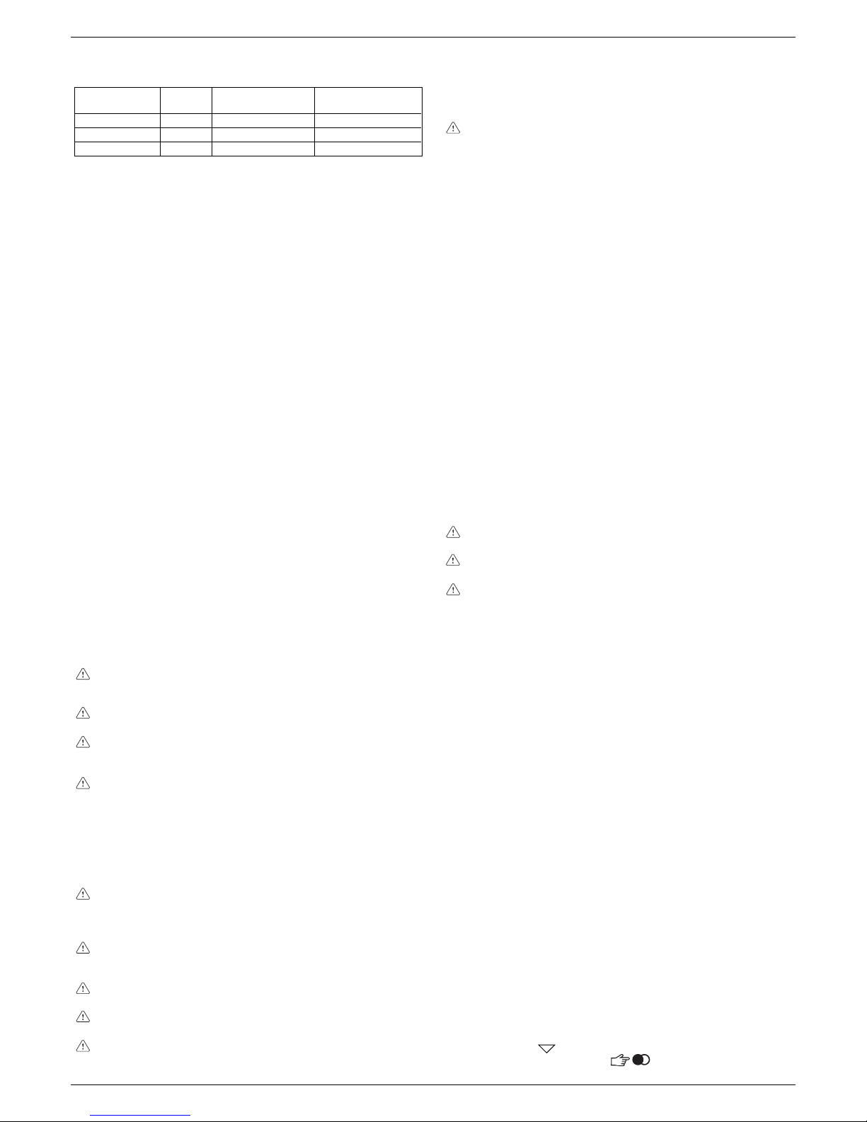
2222
2222
22
EXCLUSIEXCLUSI
EXCLUSIEXCLUSI
EXCLUSI
VE BOILER GREEN 30 BVE BOILER GREEN 30 B
VE BOILER GREEN 30 BVE BOILER GREEN 30 B
VE BOILER GREEN 30 B
.S.S
.S.S
.S
.I.I
.I.I
.I
..
..
.
Avant de raccorder l’appareil sur le réseau de gaz, vérifie si:
• les normes en vigueur ont été respectées
• le type de gaz est celui pour lequel l’appareil est équipé
• les tuyauteries sont propres.
Au terme du montage, vérifiez si les joints exécutés sont étanches conformément aux normes en vigueur.
La canalisation de gaz est prévue à l’extérieur. Si le tuyau traverse
le mur, il doit passer à travers le trou central dans le bas du gabarit.
Nous conseillons de monter sur la ligne du gaz un filtre de dimension adéquate si le réseau de distribution contient des particules
solides.
Pour accéder aux branchements électriques, procédez de la sorte:
- ôtez le manteau en dévissant les vis de fixation (A) (fig. 3)
- soulevez la façade de bord et faites-la pivoter vers l’avant
- ouvrez les couvre-bornier en les faisant glisser dans le sens
des flèches (fig. 6: B branchements haute tension 230 V, C
branchements basse tension).
Le branchement sur le secteur doit s’effectuer à travers un dispositif
de séparation avec ouverture omnipolaire d’au moins 3,5 mm
(EN 60335-1, catégorie III).
L’appareil fonctionne avec un courant alternatif de 230 Volt/50 Hz
et une puissance électrique de 150W. Il est conforme à la norme
EN 60335-1.
Le branchement sur une mise à la terre sûre, conforme aux normes
en vigueur, est obligatoire.
Nous conseillons en outre d’effectuer le branchement d’une phase
neutre (L-N).
La chaudière peut fonctionner avec alimentation phase-neutre
ou phase-phase. Pour les alimentations dépourvues de référence
à la terre l’utilisation d’un transformateur d’isolement avec
secondaire ancré à la terre est nécessaire.
Le conducteur de mise à la terre doit mesurer 2 cm de plus
que les autres.
Il est interdit d’utiliser les tuyaux de gaz et(ou) d’eau pour
effectuer la mise à la terre des appareils électriques.
L’installateur est responsable de la mise à la terre de l’appareil;
le fabricant décline toute responsabilité en cas de préjudices
causés par une erreur ou l’absence de mise à la terre.
Pour le branchement électrique utilisez le câble d’alimentation
fourni.
Le thermostat d’ambiance et(ou) le programmateur horaire se
branchent de la façon indiquée sur le schéma électrique de la
page 114.
Si vous remplacez le câble d’alimentation, utilisez un câble de
type HAR H05V2V2-F, 3 x 0,75 mm
2
, Ø externe maxi 7 mm.
Le collecteur d’évacuation (A, fig. 5) recueille: les condensats,
l’eau qui sort éventuellement de la soupape de sécurité et l’eau
de vidange de l’installation.
Le collecteur doit être raccordé, à l’aide d’un tuyau en
caoutchouc, sur un système de récolte et d’évacuation
approprié terminant dans l’évacuation des eaux blanches et
conformément aux normes en vigueur.
Le diamètre extérieur du collecteur est de 20 mm: nous vous
conseillons donc d’utiliser un tuyau en caoutchouc de18-19
mm de diamètre que vous serrerez avec un collier (non fourni).
Le fabricant décline toute responsabilité en cas de préjudices
causés par l’absence d’évacuation.
La ligne de raccordement de l’évacuation doit être parfaitement
étanche.
Le constructeur de la chaudière n’est pas responsable des
préjudices éventuellement causés par l’intervention de la
soupape de sécurité.
Il est essentiel que la sonde extérieure soit correctement mise en
place pour le bon fonctionnement du contrôle climatique.
La sonde doit être montée à l’extérieur de l’édifice à chauffer, à
environ 2/3 de la hauteur de la façade au NORD ou NORD-OUEST
et loin des conduits de fumées, portes, fenêtres et zones
ensoleillées.
Fixation au mur de la sonde extérieure (fig. 4)
- Dévisser le couvercle de protection de la sonde en le faisant
tourner en sens antihoraire pour accéder au bornier et aux trous
de fixation
- Tracer les points de fixation en vous servant du boîtier de
confinement comme gabarit
- Oter le boîtier et percer les trous pour les chevilles à expansion
de 5x25
- Fixer le boîtier au mur à l’aide des deux chevilles fournies
- Dévissezr l’écrou du presse-câble, introduire un câble bipolaire
(ayant une section de 0,5 à 1mm
2
, non fourni) pour brancher la
sonde sur la chaudière
- Pour le branchement électrique de la sonde extérieure, consulter
le chapitre “Branchements électriques”
- Visser à fond l’écrou du presse-câble et refermer le couvercle
du boîtier de protection.
La sonde doit être montée sur un pan de mur lisse; en cas de
briques apparentes ou de mur très irrégulier, prévoir une aire
de contact lisse.
La longueur maximum du branchement entre la sonde
extérieure et la chaudière est de 30 m.
Le câble de branchement entre la sonde et la chaudière doit
être dépourvus de raccords; si cela est indispensable, ils
doivent être étanches et correctement protégés.
Les gaines éventuelles du câble de branchement doivent être
séparées des câbles sous tension (230 V ca).
La position et la dimension des raccordements hydrauliques sont
indiquées de façon détaillée en fig. 2:
A-retour chauffage 3/4”
B-départ chauffage 3/4”
C-raccordement du gaz 3/4”
D-sortie sanitaire 1/2”
E-entrée sanitaire 1/2”
F-plaque de support
G- gabarit de pré-montage
Si la dureté de l’eau dépasse 28°Fr, nous conseillons d’utiliser un
adoucisseur afin d’empêcher les dépôts calcaires.
Après avoir effectué les raccordements hydrauliques, vous pouvez
procéder au remplissage des installations. Cette opération doit
s’effectuer sur l’installation froide en procédant de la sorte:
Circuit sanitaire (fig. 7)
- ouvrir le robinet d’entrée de l’eau froide (H) pour remplir le ballon
- pour vérifier que le ballon est rempli, ouvrir un robinet de l’eau
chaude et attendre que l’eau s’écoule
Circuit de chauffage (fig. 7)
- s’assurer que la vanne de vidange installation (B) soit fermée
- ouvrir de 2 ou 3 tours le bouchon du purgeur d’air automatique
(C)
- ouvrir le robinet de remplissage (I) jusqu’à ce que la pression
indiquée par le manomètre (D) soit à peu près de 1,5 bars (bleue
zone)
- ouvrir le purgeur d’air manuel (E) et le refermer une fois
l’opération soit terminée; si nécessaire répéter cette opération
jusqu’à ce qu’il ne sorte plus d’air du purgeur manuel (E)
- refermer le robinet de remplissage (I)
- quand la chaudière est alimentée électriquement, elle effectue
un cycle automatique d’air durant environ 2 minutes. Pendant
cette opération l’écrit “SF” défile et les “indicateurs de sélection
des fonctions”
s’éclairent en séquence. Pour écourter ce
cycle, appuyer sur la touche .
de l’installation (par exemple liquides antigel, de filmification, etc..) si les
caractéristiques de l’eau sont dans les plages de valeur indiquées dans le
tableau.
Parametrès unité de Eau du circuit Eau de
mesure de chauffage remplissage
Valeur PH 7 ÷ 8 -
Dureté ° F - 15 ÷20
Aspect - limpide
3 - RACCORDEMENTS HYDRAULIQUES
4 - INSTALLATION DE LA SONDE EXTERIEURE
5 - RECOLTE DES CONDENSATES
6 - RACCORDEMENT DU GAZ
7 - BRANCHEMENT ELECTRIQUE
8 - REMPLISSAGE DES INSTALLATIONS, ELIMINATION
DE L’AIR ET VIDANGE DES INSTALLATIONS
Page 23
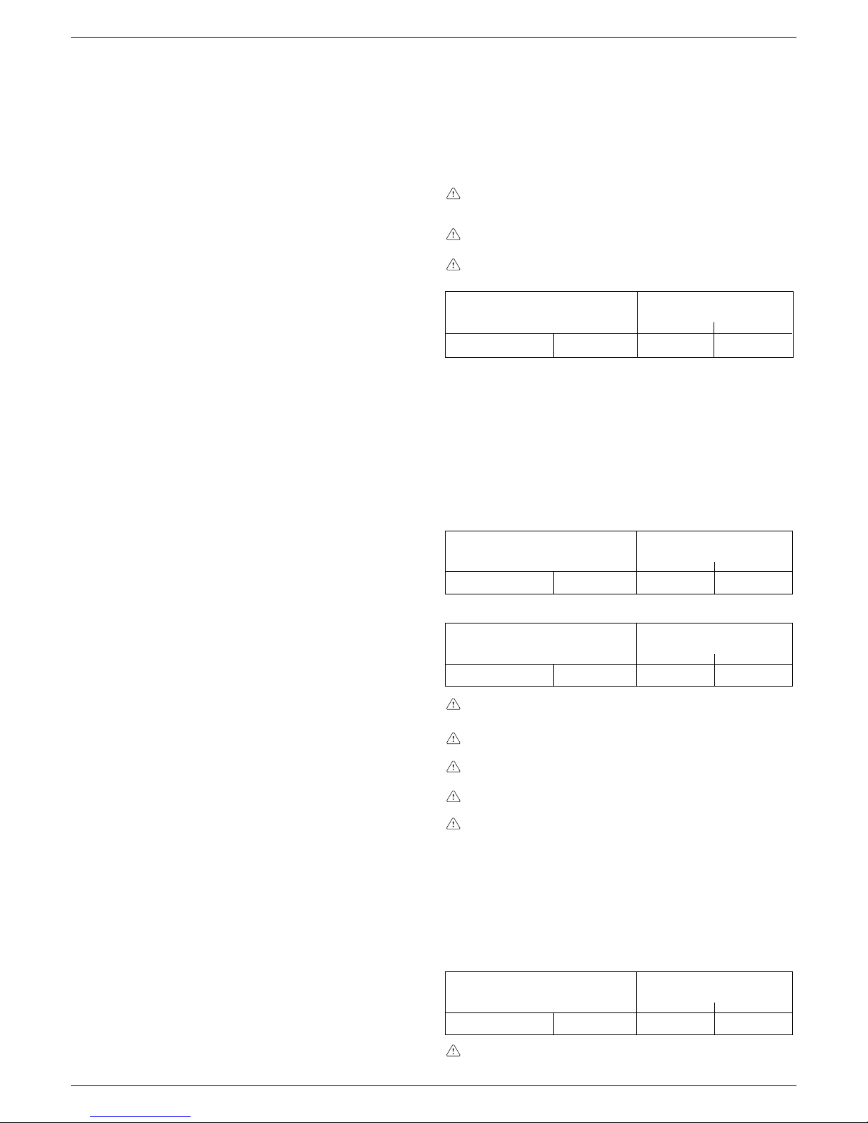
2323
2323
23
FRANÇAIS
Pour réaliser l’évacuation des produits de combustion consultez
les normes en vigueur. n fonctionnement est constamment contrôlé
par un pressostat. La chaudière est fournie sans kit d’évacuation
des fumées/d’aspiration de l’air car vous pouvez utiliser les
accessoires pour appareils à chambre étanche et tirage forcé les
mieux adaptés aux caractéristiques de votre installation. Pour
extraire les fumées et rétablir l’air comburant de la chaudière il est
indispensable d’utiliser des tuyauteries originales et d’effectuer
correctement le raccordement, de la façon indiquée par les instructions fournies avec les accessoires pour fumées. Vous pouvez
raccorder plusieurs appareils sur un seul conduit de cheminée à
condition qu’ils aient tous une chambre étanche.
CONFIGURATIONS POSSIBLES DE L’ÉVACUATION (fig. 8)
La chaudière est homologuée pour les configurations suivantes
de l’évacuation:
B23P-B53P Aspiration dans l’ambiant et évacuation à l’extérieur.
C13 Evacuation murale concentrique. Les tuyaux peuvent être
indépendants au départ de la chaudière mais les sorties
doivent être concentriques ou assez proches pour subir les
mêmes conditions de vente (pas plus de 50 cm).
C23 Evacuation concentrique en conduit de fumées commun
(aspiration et évacuation dans le même conduit).
C33 Evacuation concentrique sur le toit. Sorties comme le C13.
C43 Evacuation et aspiration en conduits de fumées communs
séparés, mais soumis au mêmes conditions de vent.
C53 Evacuation et aspiration murale ou sur le toit et de toute
façon dans des zones de pression différente. L’évacuation
et l’aspiration ne doivent jamais se trouver sur des murs
opposés.
C63 Evacuation et aspiration réalisées en tuyaux du commerce
et certifiés séparément (1856/1).
C83 Evacuation en conduit de cheminée simple ou commune et
aspiration murale.
INSTALLATION “FORCÉE OUVERTE”
(TYPE B23P-B53P)
Conduit d’évacuation des fumées de ø 80 mm
Le conduit d’évacuation des fumées peut être orienté dans la
direction la plus adéquate aux besoins de l’installation.
Pour effectuer le montage suivre les instructions fournies avec le
kit.
Dans cette configuration, la chaudière est raccordée sur le conduit
d’évacuation des fumées de ø 80 mm à l’aide d’un adaptateur de
ø 60-80 mm.
Dans ce cas l’air comburant est prélevé dans le lieu
d’installation de la chaudière qui doit être un local technique
approprié, muni d’aération.
Les conduits d’évacuation des fumées non isolés sont des
sources de danger potentielles.
Prévoir une inclinaison du conduit d’évacuation des fumées
de 1% vers la chaudière.
longueur maximum conduit
d’évacuation ø 80 (m)
0,5 0,854230 B.S.I.
INSTALLATION “ÉTANCHE” (TYPE C)
La chaudière doit être raccordée sur les conduits coaxiaux ou
dédoublés d’évacuation des fumées et d’aspiration de l’air, qui
devront être amenés à l’extérieur. Sans eux, la chaudière ne peut
pas fonctionner.
Conduits coaxiaux (ø 60-100)
Les conduits coaxiaux peuvent être orientés dans la direction la
mieux adaptée aux exigences de l’installation, mais il faut faire
très attention à la température extérieure et à la longueur du
conduit.
Horizontale
longueur rectiligne
conduit coaxial ø 60-100 (m)
7,8030 B.S.I. 0,5 0,85
Verticale
longueur rectiligne
conduit coaxial ø 60-100 (m)
8,8030 B.S.I. 0,5 0,85
La longueur rectiligne s’entend sans coude, ni terminaux
d’évacuation, ni raccords.
Prévoir une inclinaison du conduit d’évacuation des fumées
de 1% vers le collecteur d’évacuation.
Les conduits d’évacuation non isolés sont des sources de
danger potentielles.
La chaudière adapte automatiquement la ventilation en
fonction du type d’installation et de la longueur du conduit.
L’utilisation de conduits plus longs comporte une perte de
puissance de la chaudière.
Pour effectuer le montage suivre les instructions fournies avec le
kit.
Conduits coaxiaux (ø 80-125 mm)
Les conduits coaxiaux peuvent être orientés dans la direction la
mieux adaptée aux exigences de l’installation.
Pour effectuer le montage suivre les instructions fournies avec le
kit pour les chaudière à condensation.
longueur rectiligne
conduit coaxial ø 80-125 (m)
1830 B.S.I. 0,5 0,85
pertes de charge (m)
coude 45°
coude 90°
pertes de charge (m)
coude 45°
coude 90°
pertes de charge (m)
coude 45°
coude 90°
pertes de charge (m)
coude 45° coude 90°
La longueur rectiligne s’entend sans coude, ni terminaux
d’évacuation, ni raccords.
REMARQUE: la phase de purge d’air s’effectue avec les 2 purges
d’air automatique, C et F.
REMARQUE: même si la chaudière est munie d’un dispositif de
remplissage semiautomatique, vous devez effectuer le premier
remplissage de l’installation en agissant sur le robinet I avec
chaudière éteinte.
Vidange du circuit de chauffage (fig. 7)
Pour vider l’installation procédez de la sorte:
- éteindre la chaudière
- fermer les dispositifs d’interception de l’installation thermique
et sanitaire
- ouvrir le purgeur d’air automatique (C)
- dévisser le robinet de vidange de la chaudière (B), en
maintenant en place le coude du flexible d’évacuation pour
éviter qu’il se débôite
- l’eau s’écoulera par le collecteur d’évacuation (A)
- videz les points les plus bas de l’installation.
Vidange du circuit sanitaire (fig. 7)
Si un risque de gel se présente, vidangez l’installation sanitaire
en procédant de la sorte:
- fermer le robinet général du réseau hydrique
- dévisser le bouchon du porte-caoutchouc (G)
- raccorder un tube de plastique sur le porte-caoutchouc de la
soupape de sécurité du ballon (G)
- desserrer le dispositif de vidange de la soupape
- ouvrir tous les robinets d’eau chaude et froide
- videz les points les plus bas de l’installation.
ATTENTION
Le collecteur doit être raccordé, à l’aide d’un tuyau en caoutchouc,
sur un système de récolte et d’évacuation approprié terminant
dans l’évacuation des eaux blanches et conformément aux normes
en vigueur. Le diamètre extérieur du collecteur est de 20 mm:
nous vous conseillons donc d’utiliser un tuyau en caoutchouc
de18-19 mm de diamètre que vous serrerez avec un collier (non
fourni). Le constructeur n’est pas responsable des inondations
éventuellement causées par l’intervention de la soupape de
sécurité.
9 - EVACUATION DES PRODUITS DE LA COMBUSTION ET
ASPIRATION DE L’AIR
Page 24

2424
2424
24
EXCLUSIEXCLUSI
EXCLUSIEXCLUSI
EXCLUSI
VE BOILER GREEN 30 BVE BOILER GREEN 30 B
VE BOILER GREEN 30 BVE BOILER GREEN 30 B
VE BOILER GREEN 30 B
.S.S
.S.S
.S
.I.I
.I.I
.I
..
..
.
La longueur rectiligne s’entend sans coude, ni terminaux
d’évacuation, ni raccords.
Conduits dédoublés (ø 80)
Les conduits dédoublés peuvent être orientés dans la direction la
mieux adaptée aux besoins du lieu d’installation.
Le conduit d’aspiration de l’air comburant peut être raccordé sur
l’entrée après avoir démonté le bouchon de fermeture fixé sur
l’adaptateur à l’aide de trois vis.
Le conduit d’évacuation des fumées doit être raccordé sur la sortie
des fumées.
Pour effectuer le montage suivre les instructions fournies avec le
kit de l’accessoire spécifique pour les chaudières à condensation.
longueur maxi rectiligne
conduit dédoublé ø 80 (m)
30 B.S.I. 35 + 35 0,5 0,85
Prévoir une inclinaison du conduit d’évacuation des fumées de
1% vers le collecteur d’évacuation.
La chaudière adapte automatiquement la ventilation en fonction
du type d’installation et de la longueur des conduits. Ne
boucher pas même partiellement les conduits
Pour connaître les longueurs maximum de chaque tuyau,
consulter les graphiques.
L’utilisation de conduits plus longs comporte une perte de
puissance de la chaudière.
pertes de charge (m)
coude 45° coude 90°
CONDUITS COAXIAUX POUR EVACUATION
FUMEES/ASPIRATION AIR
CONDUITS SEPARES POUR EVACUATION
FUMEES/ASPIRATION AIR
CONDUITS FUMEES ASPIRATION
DANS L’AMBIANT
adaptateur
Ø 60-80
LONGUEUR CONDUIT D’ASPIRATION (m)
LONGUEUR CONDUIT
D’EVACUATION (m)
0
10
20
30
40
50
60
70
80
90
0 102030405060
910
11 12
Page 25
2525
2525
25
FRANÇAIS
Circuit chauffage: débit calorifique nominal (Hi) kW 30,00
kcal/h 25.800
Puissance thermique nominale (80°-60°) kW 29,01
kcal/h 24.949
Puissance thermique nominale (50°-30°) kW 31,41
kcal/h 27.013
Débit calorifique réduit (Hi) kW 6,00
kcal/h 5.160
Puissance thermique réduite (80°-60°) kW 5,73
kcal/h 4.928
Puissance thermique réduite (50°-30°) kW 6,31
kcal/h 5.428
Circuit sanitaire: débit calorifique nominal kW 30,00
kcal/h 25.800
Puissance thermique maximale (*) kW 30,00
kcal/h 25.800
Débit calorifique réduit kW 6,00
kcal/h 5.160
Puissance thermique minimale (*) kW 6,00
kcal/h 5.160
Rendement utile Pn maxi - Pn mini (80°-60°) % 96,7 - 95,5
Rendement utile 30% (47° retour) % 102,0
Rendement de combustion % 96,9
Rendement utile Pn maxi - Pn mini (50°-30°) % 104,7 - 105,2
Rendement utile 30% (30° retour) % 108,1
Catégorie II2H3P
Puissance électrique W 150
Tension d’alimentation V - Hz 230 - 50
Degré de protection IP X5D
Pertes au niveau de cheminée et manteau avec brûleur éteint % 0,10 - 0,80
Exercice de chauffage
Pression - températur emaximale bar - °C 3 - 90
Pression minimum pour fonctionnement standard bar 0,25 ÷ 0,45
Plage de sélection de la température °C 20 - 80
Pompe: prévalence maximum disponible pour l’installation mbar 300
avec un débit de l/h 1000
Vase d’expansion à membrane l 10
Pré-charge du vase d’expansion (chauffage) bar 1
Exercice sanitaire
Pression maxi bar 8
Pression mini bar 0,2
Débit spécifique selon EN625 l/min 20,2
Plage de sélection de la température eau sanitaire °C 35 - 60
Régulateur de flux l/min 15
Ballon l60
Pression du gaz
Pression nominale gaz méthane (G20) mbar 20
Pression nominale gaz liquide GPL (G31) mbar 37
Raccordements hydrauliques
Entrée-sortie chauffage Ø 3/4”
Entrée-sortie sanitaire Ø 1/2”
Entrée gaz Ø 3/4”
Dimensions de la chaudière
Hauteur mm 940
Largeur mm 600
Profondeur mm 450
Poids chaudière kg 68
Débits (G20)
Débit air Nm3/h 36,234
Débit fumées Nm3/h 39,143
Débit massique fumées (maxi) gr/s 13,13
Débit massique fumées (mini) gr/s 2,72
Performances du ventilateur
Pression résiduelle avec tuyaux concentriques 0,5 + coude 90° Pa 142
Tuyaux évacuation des fumées concentriques
Diamètre mm 60 - 100
Longueur maximum m 7,80
Perte causée par l’introduction d’un coude 90°/45° m 0,85/0,50
Diamètre du trou de traversée du mur mm 105
Tuyaux évacuation des fumées concentriques
Diamètre mm 80 - 125
Longueur maximum m 18**
Perte causée par l’introduction d’un coude 90°/45° m 0,85/0,50
Tuyaux évacuation des fumées séparés
Diamètre mm 80
Longueur maximum m 35 + 35
Perte causée par l’introduction d’un coude 90°/45° m 0,85/0,5
Installation forcée ouverte (B23P/B53P)
Diamètre mm 80
Longueur maximum m 42
Perte causée par l’introduction d’un coude 90°/45° m 0,85/0,5
Exclusive Boiler
Green 30 B.S.I.
10 - DONNEES 10 - DONNEES
10 - DONNEES 10 - DONNEES
10 - DONNEES
TECHNIQTECHNIQ
TECHNIQTECHNIQ
TECHNIQ
UESUES
UESUES
UES
Page 26

2626
2626
26
EXCLUSIEXCLUSI
EXCLUSIEXCLUSI
EXCLUSI
VE BOILER GREEN 30 BVE BOILER GREEN 30 B
VE BOILER GREEN 30 BVE BOILER GREEN 30 B
VE BOILER GREEN 30 B
.S.S
.S.S
.S
.I.I
.I.I
.I
..
..
.
Gaz liquide
propane (G31)
PARAMETRES
Méthan
(G20)
Indice de Wobbe inférieur
(à 15°C-1013 mbar) MJ/m3S 45,67 70,69
Puissance calorifique inférieure MJ/m3S 34,02 88
Pression nominale d’alimentation mbar (mm H2O) 20 (203,9) 37 (377,3)
Pression minimum d’alimentation mbar (mm H
2
O) 10 (102,0)
Nombre d’injecteurs brûleur n° 1 1
Diamètre brûleur Ø mm 70 70
Diamètre injecteur Ø mm 6,7 4,7
Longueur du brûleur mm 147 147
Débit gaz au maxi chauffage Sm
3
/h 3,17
kg/h 2,33
Débit gaz au maxi sanitaire Sm
3
/h 3,17
kg/h 2,33
Débit gaz au mini chauffage Sm3/h 0,63
kg/h 0,47
Débit gaz au mini sanitaire Sm
3
/h 0,63
kg/h 0,47
Vitesse du ventilateur à l’allumage tours/min 3.700 3.700
Vitesse du ventilateur au maxi tours/min 5.600 5.600
Vitesse du ventilateur au mini tours/min 1.400 1.400
DESCRIPTION DU BALLON
Type du ballon Acier inox
Disposition du ballon Vertical
Disposition de l’échangeur Vertical
Contenance du ballon l 60
Contenance du serpentin l 3,87
Surface d’échange m
2
0,707
Plage de sélection de la température eau sanitaire °C 35 - 60
Regulateur de flux l/min 15
Quantité d’eau puisée en 10’ avec ∆t 30 °C l 202
Pression maximale du ballon bar 8
NOx classe 5
Valeurs d’émission avec le débit maximum et minimum du gaz G20***
Maximum CO s.a. infèrieur à p.p.m. 230
CO2 % 9,0
NOx s.a. infèrieur à p.p.m. 60
∆t fumées °C 60
Minimum CO s.a. infèrieur à p.p.m. 40
CO2 % 9,0
NOx s.a. infèrieur à p.p.m. 40
∆t fumées °C 34
* Valeur moyenne entre différentes conditions de fonctionnement.
** Calculé avec une coude 90°, 17 rallonges de 1 mètre et un collecteur horizontal de 1 mètre.
*** Vérification effectuée avec tuyau concentric ø 60-100, longueur 0,85m, température eau 80-60°C.
11 - TABLEAU MULTIGAZ
Page 27

2727
2727
27
FRANÇAIS
Description des commandes
Sélecteur de température de l’eau du chauffage: permet de
configurer la valeur de la température de l’eau de chauffage.
Sélecteur de température de l’eau sanitaire: permet de
configurer la valeur de la température de l’eau sanitaire stockée
dans le ballon.
Sélecteur permettant de configurer les paramètres: utilisé
dans la phase de tarage et programmation.
Touche de fonction:
- ON chaudière alimentée électriquement, en attente de
demande de fonctionnement (
- )
- OFF chaudière alimentée électriquement mais par
disponible pour le fonctionnement
- RESET permet de rétablir le fonctionnement après une anomalie du fonctionnement
Touche du mode de fonctionnement: la touche
permet
de choisir le type de fonctionnement desiré: (hiver) ou
(été).
Touche Info: permet d’afficher en séquence les informations sur
l’état du fonctionnement de l’appareil.
Touche de remplissage de l’installation: si vous l’enfoncez, la
chaudière remplit automatiquement l’installation jusqu’à la
valeur de la pression voulue (entre 1 et 1,5 bars).
La chaudière produit du chauffage et de l’eau chaude sanitaire.
Le tableau de commande (fig. 13) contient les principales fonctions
de contrôle et de gestion de la chaudière.
Description of display symbols
14
13
échelle graduée de la température de l’eau de
chauffage avec icône de fonction chauffage
échelle graduée de la température de l’eau sanitaire
avec icône de fonction sanitaire
icône fonction sanitaire
icône anomalie (pour détails, consultez page 31)
icône reset (pour détails, consultez page 31)
valeur de la pression
icône du branchement de la sonde extérieure
température du chauffage/sanitaire
ou
anomalie du fonctionnement (par ex. 10 - anomalie
manque de flamme)
indicateur de sélection des fonctions (se place en face
du type de fonctionnement choisi:
hiver ou
été)
icône du fonctionnement du brûleur
icône de la fonction antigel active
icône de la fonction remplissage de l’installation
icône du besoin de remplissage
Sélecteur
de température
de l’eau
sanitaire
Touche du
mode de
fonctionnement
Touche
fonction
ON-OFF-RESET
Touche de
remplissage
installation
Sélecteur de
température
de l’eau
du chauffage
Touche
INFO
Sélecteur
permettant de
configurer les
paramètres
12 - ALLUMAGE ET FONCTIONNEMENT
Page 28

2828
2828
28
EXCLUSIEXCLUSI
EXCLUSIEXCLUSI
EXCLUSI
VE BOILER GREEN 30 BVE BOILER GREEN 30 B
VE BOILER GREEN 30 BVE BOILER GREEN 30 B
VE BOILER GREEN 30 B
.S.S
.S.S
.S
.I.I
.I.I
.I
..
..
.
Allumage de l’appareil
Pour allumer la chaudière vous devez:
- accéder au robinet du gaz à travers les fentes du couvre-raccords
situé au bas de la chaudière
- ouvrir le robinet de gaz, en faisant pivoter en sens antihoraire la
poignée, pour laisser arriver le combustible (fig. 15)
- mettre la chaudière sous tension.
Quand la chaudière est alimentée électriquement, elle effectue
un cycle automatique d’air durant environ 2 minutes. Pendant cette
opération l’écrit “SF” défile (fig. 16) et les “indicateurs de sélection
des fonctions”
s’éclairent en séquence. Pour écourter ce cycle,
appuyer sur la touche
. Si la vérification s’achève
correctement, la chaudière est prête à fonctionner.
La chaudière se rallume dans l’état dans lequel se trouvait
avant d’être éteinte: si la chaudière se trouvait en mode hiver
lorsqu’elle a été éteinte, elle se rallume en mode hiver; si elle
se trouvait dans l’état OFF, l’afficheur montre deux segments
en son centre (fig. 17). Appuyez sur la touche
pour activer
le fonctionnement.
Choisir le type de fonctionnement désiré en appuyant sur la touche
“mode de fonctionnement” jusqu’à posittioner le symbole
sur:
HIVER
ÉTÉ
Fonction HIVER (fig. 18)
L’indicateur dans cette position, la chaudière produit eau chaude
pour le chauffage et fournie l’eau au ballon pour permettre la
préparation de l’eau chaude sanitaire. Dans cette position la fonction
S.A.R.A Booster est active (cf. chapitre “Fonctions de la chaudière”).
Fonction ÉTÉ (fig. 19)
L’indicateur dans cette position, la chaudière fournie au ballon
l’eau, à une température predéfinie, pour la préparation de l’eau
chaude sanitaire.
15
position
d’ouverture
16
Réglage de la température de l’eau de chauffage
Si vous faites tourner le sélecteur A (fig. 20), après avoir placé le sélecteur
de fonction sur hiver
, vous pouvez régler la température de l’eau de
chauffage.
En sens horaire la température augmente, en sens contraire elle diminue.
Les segments de la barre graphique s’éclairent (tous les 5°C) au fur et à
mesure que la température augmente. L’afficheur montre la valeur de la
température sélectionnée.
Réglage de la température de l‘eau de chauffage avec une sonde
extérieure branchée
Lorsqu’une sonde extérieure est installée, le système choisit
automatiquement la valeur de la température de départ et adapte
rapidement la température ambiante en fonction des variations de la
température extérieure. Seul le segment central de la barre apparaît éclairé
(fig. 21). Si vous voulez modifier la valeur de la température, en l’augmentant
ou la diminuant par rapport à celle que la carte électronique calcule
automatiquement, vous pouvez agir sur le sélecteur de température de
l’eau de chauffage. En sens horaire la valeur de correction de la température
augmente, en sens antihoraire elle diminue. Les segments de la barre
graphique s’éclairent (à chaque niveau de confort); la plage de correction
est comprise entre - 5 et + 5 niveaux de confort (fig. 21). Lorsque vous
choisissez le niveau de confort, l’afficheur montre, dans l’aire des chiffres,
le niveau de confort, sur la barre graphique le segment correspondant (fig.
22).
Réglage de la température de l’eau sanitaire
Pour régler la température de l’eau sanitaire stockée dans le ballon, faites
tourner le sélecteur B (fig. 23) en sens horaire la température augmente,
en sens contraire elle diminue. Les segments de la barre graphique
s’éclairent (tous les 3°C) au fur et à mesure que la température augmente.
L’afficheur montre la valeur de la température sélectionnée.
Pendant le choix de la température, de chauffage ou bien sanitaire, l’afficheur
montre la valeur que vous êtres en train de sélectionner. Lorsque votre
choix est fait, après 4 secondes environ, la modification est mémorisée
et l’afficheur montre à nouveau la température de départ détectée par la
sonde.
17
18
19
A
20
21
22
°C
+ 4/5
+ 3
+ 2
+ 1
0
- 1
- 2
- 3
- 4/5
Page 29
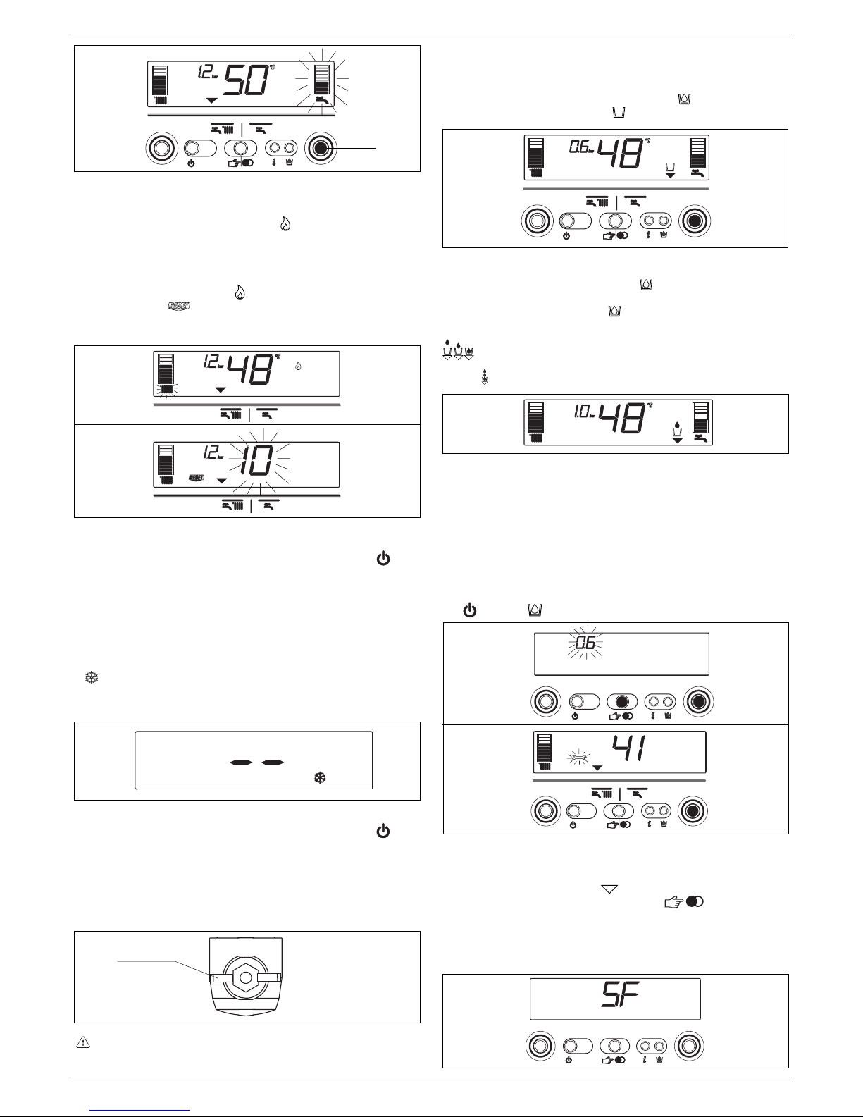
2929
2929
29
FRANÇAIS
Mise en service de la chaudière
Réglez le thermostat d’ambiance sur la température voulue
(environ 20 °C). Si de la chaleur est demandée, la chaudière
démarre et l’afficheur montre l’icône
(fig. 24). La chaudière
reste alors en marche jusqu’à ce que les températures configurées
soient atteintes, puis elle se met en stand-by. Si une anomalie
se présente à l’allumage ou pendant le fonctionnement, la
chaudière effectue un “arrêt de sécurité”.
L’afficheur montre la flamme
et le code d’anomalie d’affiche
avec l’inscription
(fig. 25). Pour connaître la description et la
procédure de rétablissement des anomalies consultez le chapitre
“Anomalies”.
Extinction
Extinction provisoire
En cas de courtes absences, appuyez sur la touche
pour
éteindre la chaudière. Dans la zone centrale de l’afficheur
apparaissent deux segments (fig. 17). De la sorte l’alimentation
électrique et l’alimentation en combustible sont actives mais la
chaudière est protégée par les systèmes:
- antigel (fig. 26): lorsque la température de l’eau de la chaudière
descend au-dessous des valeurs de sécurité, le circulateur et
le brûleur s’activent à la puissance minimum pour ramener la
température de l’eau à la valeur de sécurité (35 °C). Le symbole
s’éclaire sur l’afficheur.
- antiblocage du circulateur: un cycle de fonctionnement s’active
toutes les 24 heures.
Extinction pendant de longues périodes
En cas d’absence prolongée, appuyez sur la touche
pour
éteindre la chaudière (fig. 17). Dans la zone centrale de l’afficheur
apparaissent deux segments. Placez l’interrupteur général de
l’installation sur “éteint”. Fermez le robinet de gaz placé sous la
chaudière en faisant pivoter la poignée en sens horaire (fig. 27).
Dans ce cas les systèmes antigel et antiblocage sont
désactivés. Videz l’installation thermique ou protégez-la de
façon adéquate avec du liquide antigel de qualité. Videz
l’installation sanitaire
23
B
robinet
fermé
26
27
Fonctions de la chaudière
Remplissage semi-automatique
La chaudière est équipée d’un dispositif de remplissage semi
automatique qui s’active à l’aide de la touche
lorsque l’afficheur
montre l’icône correspondante
(fig. 28).
Si cette condition se présente, la pression de l’installation n’est
pas correcte, la chaudière continue cependant à fonctionner
normalement. Appuyez sur la touche
pour activer la procédure
de remplissage. Si vous appuyez encore sur la touche de
remplissage de l’installation
vous pouvez interrompre la
séquence de remplissage. Pendant la phase de remplissage,
l’afficheur montre en cascade les gouttes de l’icône de remplissage
et la valeur croissante de la pression (fig. 29).
A la fin du remplissage, l’afficheur montre pendant un instant
l’icône
puis il s’éteint.
Remarque: pendant le remplissage, la chaudière n’exécute
aucune autre fonction, par exemple si vous effectuez un
prélèvement sanitaire, la chaudière n’est pas en mesure de fournir
l’eau chaude tant que le remplissage n’est pas achevé.
Remarque: si la valeur de pression de charge de l’installation
atteint 0.6 bars, la valeur sur le display commence à clignoter
(fig. 30a); si elle descende au-dessous du minimum de sécurité
(0.3 bar), l’afficheur montre l’anomalie 41 (fig. 30b) pendant un
court instant, après quoi, si l’anomalie persiste, il montre le code
d’anomalie 40 (cf. chapitre “Anomalies”).
Si anomalie 40 s’affiche, procédez au rétablissement en appuyant
sur
puis sur pour activer la procédure de remplissage de
l’installation. Après le rétablissement de l’anomalie 40, la chaudière
effectue un cycle automatique d’air durant environ 2 minutes.
Pendant cette opération l’écrit “SF” défile (fig. 31) et les “indicateurs
de sélection des fonctions”
s’éclairent en séquence. Pour
écourter ce cycle, appuyer sur la touche
. Si vous devez
répéter plusieurs fois la procédure de remplissage de l’installation,
nous vous conseillons de vous adresser au Service Après-vente
pour qu’il vérifie l’étanchéité de l’installation (vois s’il n’y a pas
de fuites).
28
29
24
25
30a
30b
31
Page 30

3030
3030
30
EXCLUSIEXCLUSI
EXCLUSIEXCLUSI
EXCLUSI
VE BOILER GREEN 30 BVE BOILER GREEN 30 B
VE BOILER GREEN 30 BVE BOILER GREEN 30 B
VE BOILER GREEN 30 B
.S.S
.S.S
.S
.I.I
.I.I
.I
..
..
.
Information
Si vous appuyez sur la touche
, l’afficheur s’éteint et seule
l’inscription InFO reste (fig. 32). En appuyant sur la touche
vous
pouvez afficher certaines informations utiles au fonctionnement
de la chaudière. Chaque fois que vous appuyez sur la touche
vous passez à l’information suivante. Si vous n’appuyez plus sur
la touche le système sort automatiquement de la fonction.
Liste Info:
Info 0 affiche l’inscription InFO (fig. 32)
Info 1 uniquement si la sonde extérieure est branchée, affiche
la température extérieure (par ex 12 °C) (fig. 33).
Les valeurs affichés sont comprises entre - 30 °C et 35 °C.
Au-delà de ces valeurs, l’afficheur montre “- -”
Info 2 affiche la pression de charge de l’installation (fig. 34)
36
37
35
34
33
32
Info 3 affiche la température de chauffage configurée (fig. 35)
Info 4 affiche la température de l’eau sanitaire configurée (fig. 36)
Info 5 affiche la consigne de température de chauffage du
deuxième circuit, uniquement si celui-ci est branché.
Fonction S.A.R.A.
Si vous avez sélectionné la position “hiver” vous pouvez activer la
fonction S.A.R.A. (Système Automatique Réglage Ambiance).
Si vous sélectionnez, en faisant tourner le sélecteur de température
de l’eau de chauffage, une température comprise entre 55 et 65
°C, vous activez le système d’autoréglage S.A.R.A.: selon la
température configurée sur le thermostat d’ambiance et le temps
nécessaire pour l’atteindre, la chaudière varie automatiquement
la température de l’eau de chauffage, en réduisant le temps de
fonctionnement et en garantissant un fonctionnement plus
confortable et une économie d’énergie.
D’autres informations sont consultables en appuyant pendant 10
secondes la touche
for 10 seconds: affichage de l’inscription
INF2.
INF2
Ligne Description d’étape Afficheur Afficheur
2 chiffres 4 chiffres
1 Température sonde départ xx 01 ° C
2 Température sonde retour xx 02 ° C
3 Température sonde ballon (*) xx 03 ° C
4 Non utilisé sur ce modèle xx Cond ° C
5 Température de la sonde de fumée xx (**) 05
6 Température sonde deuxième circuit de chauffe xx 06 ° C
7 Non utilisé sur ce modèle xx 07
8 Vitesse ventilateur /100 xx FAN
9 Non utilisé sur ce modèle xx 09
10 Non utilisé sur ce modèle xx 10
11 État du compteur de nettoyage de l’échangeur bH xxxx
12-19 Historique des codes anomalie xx HIS0-HIS7
Liste INF2
Remarque (*): si la sonde ballon est interrompue ou en court circuit, l’afficheur indiquera “- -”.
(**): si il est présent aussi le point (.) sur l’affichage la température de la sonde de fumée est 100 + la valeur affichée
Page 31

3131
3131
31
FRANÇAIS
Anomalies
Lorsqu’une anomalie de fonctionnement se présente, la flamme
s’éteint sur l’afficheur, qui montre un code clignotant et,
simultanément ou pas les icônes
et . Le tableau ci-
dessous vous donne la description des anomalies.
(D) Définitive
(T) Temporaire, la chaudière tente de résoudre elle-même l’anomalie.
(°) Voir remarque à la page suivante.
(*) Si ces deux erreurs se présentent, vérifiez la pression indiquée par le manomètre. Si la pression est insuffisante (< 0,4 bar, zone rouge), procédez
aux opérations de remplissage décrite au chapitre “Remplissage et vidange de l’installation”.
Si la pression de l’installation est suffisante (> 0,6 bar, zone bleue) la panne est due au manque de circulation de l’eau. Contactez le Service aprèsvente.
(-) Contactez le Service après-vente.
DESCRIPTION DE L’ANOMALIE Code Icône Icône
alarm
Absence de flamme (D) 10 OUI NON
Flamme parasite (T) 11 NON OUI
Nouvelle tentative d’allumage en cours (T) 12 NON NON
Anomalie câblage (T) 13 NON OUI
Anomalie câblage (D) 14 OUI NON
Flamme parasite en standby (D) 15 OUI OUI
Anomalie sur thermostat limite T (D) 20 OUI NON
Anomalie câblage (D) 21 OUI OUI
Anomalie câblage (D) 22 OUI NON
Température limite sur sonde départ (D) 24 OUI NON
Température limite sur sonde départ (T) 25 NON OUI
Température limite sur sonde retour (D) 26 OUI NON
Température limite sur sonde retour (T) 27 NON OUI
Anomalie sur différentiel sondes (D) 28 OUI OUI
Sonde de fumée surchauffée (D) 29 OUI OUI
Erreur carte électronique (D) 30 OUI NON
Erreur carte électronique (T) 31 NON OUI
Vitesse ventilateur insuffisante (D) 33 OUI OUI
Erreur ventilateur (signal TACHO) (D) 34 OUI NON
Erreur ventilateur (signal TACHO) (T) 35 NON OUI
Erreur carte électronique (T) 36 NON OUI
Vitesse ventilateur insuffisante (D) 37 OUI OUI
Erreur carte électronique (D) 38 OUI OUI
Pression hydraulique insuffisante (D*) 40 OUI NON
Pression hydraulique insuffisante (T*) 41 NON OUI
Anomalie capteur de pression (D) 42 OUI OUI
Erreur paramétrage carte électronique (D) 50-59 OUI OUI
Erreur sonde sanitaire (T°) 60 NON OUI
Erreur sonde départ (court circuit/interrompue) (D) 70 OUI OUI
Surchauffe sonde départ (T) 71 NON NON
Erreur sonde retour (court circuit/interrompue) (D) 72 OUI OUI
Anomalie thermostat sécurité plancher chauffant (T) 77 NON OUI
Absence circulation eau (T) 78 NON OUI
Absence circulation eau (D) 79 OUI NON
Anomalie système (D) 80 OUI OUI
Anomalie système (T) 81 NON OUI
Anomalie système (D) 82 OUI OUI
Anomalie système (T) 83 NON OUI
Nettoyage l’échangeur primaire (-) 91 NON OUI
Anomalie condensats/capteur de condensats (D) 92 OUI NON
Anomalie condensats/capteur de condensats (T) 93 NON OUI
Anomalie capteur de condensats (T) 95 NON OUI
Page 32

3232
3232
32
EXCLUSIEXCLUSI
EXCLUSIEXCLUSI
EXCLUSI
VE BOILER GREEN 30 BVE BOILER GREEN 30 B
VE BOILER GREEN 30 BVE BOILER GREEN 30 B
VE BOILER GREEN 30 B
.S.S
.S.S
.S
.I.I
.I.I
.I
..
..
.
Rétablissement des anomalies
Attendez environ 10 secondes avant de rétablir les conditions de
fonctionnement. Ensuite, procédez de la sorte:
1) Affichage uniquement de l’icône
L’affichage de indique le diagnostic d’une anomalie de fonctionnement
que la chaudière tente de résoudre par elle-même (arrêt temporaire). Si
la chaudière ne se remet pas à fonctionner normalement, l’afficheur montre
deux situations:
situation A (fig. 38)
disparition de
, apparition de l’icône et d’un autre code d’alarme.
Dans ce cas, procédez de la façon décrite au point 2.
situation B (fig. 39)
avec apparition de l’icône et d’un autre code d’alarme. Dans
ce cas, procédez de la façon décrite au point 3.
situation C - alarme 91 (Contactez le Service après-vente)
La chaudière dispose d’un système de diagnostic automatique qui, en
fonction des heures totalisées en conditions particulières de fonctionnement,
est en mesure de signaler la nécessité d’intervention pour le nettoyage de
l’échangeur primaire (code alarme 91). Une fois terminée l’opération de
nettoyage réalisée avec un équipement approprié fourni en accessoire, il
est nécessaire de mettre à zéro le compteur des heures totalisées en
appliquant la procédure suivante :
- débrancher l’alimentation électrique
- enlever la protection pour l’électricité en intervenant sur les vis et les
crochets de fixage
- extraire le connecteur J13 (voir schéma électrique)
- alimenter la chaudière et attendre l’apparition sur l’écran de l’alarme 13
- débrancher la tension et reconnecter le connecteur J13
- réinstaller la protection pour l’électricité et rétablir le fonctionnement de
la chaudière
REMARQUE : la procédure de mise à zéro du compteur doit être faite
après tout nettoyage de l’échangeur primaire lors de son remplacement.
2) Affichage uniquement de l’icône
(fig. 40)
Appuyez sur la touche
pour rétablir le fonctionnement. Si la chaudière
effectue l’allumage et reprend son fonctionnement normal, l’arrêt est le
fruit du hasard. Si le verrouillage se répète plusieurs fois, il est préférable
de vous adresser au Service Après-vente.
3) Affichage des icônes et (fig. 41)
Demandez l’intervention du Service Après-vente.
Remarque: anomalie sonde circuit sanitaire - 60: la chaudière
fonctionne normalement mais elle ne garantit pas la stabilité de la
température de l’eau du circuit sanitaire qui est toujours fournie à une
température d’environ 50°C. Le code anomalie ne s’affiche qu’avec la
chaudière en stand-by.
Cette chaudière est équipée de cartes électroniques de nouvelle
génération, qui permettent, en configurant/modifiant des
paramètres de fonctionnement de la machine, de mieux la
personnaliser afin de répondre aux différents besoins de
l’installation et(ou) de l’usager. Les paramètres configurables sont
indiqués sur le tableau de la page suivante.
Les opérations de configuration des paramètres doivent
s’effectuer ave la chaudière en position OFF. Pour cela appuyez
sur la touche
jusqu’à ce que l’afficheur montre “- -” (fig. 42).
Pendant la modification des paramètres la touche “mode de
fonctionnement” sert de touche ENTER (confirmation) et la
touche
sert de touche ESCAPE (sortie). Si aucune confirmation
n’est donnée dans les 10 secondes qui suivent, la valeur n’est
pas mémorisée et la valeur configurée auparavant s’applique.
Configuration du code d’accès
Appuyez en même temps sur la touche “mode de fonctionnement”
et sur la touche
pendant 10 secondes environ. L’afficheur apparaît
comme sur la fig. 43.
Saisissez le code d’accès aux fonctions de modification des
paramètres en faisant tourner le sélecteur de température d’eau
sanitaire jusqu’à la valeur voulue. Le code d’accès à la configuration
des paramètres se trouve dans le tableau de commande. Confirmez
l’entrée en appuyant sur la touche ENTER.
Modification des paramètres
Si vous faites tourner le sélecteur température de l’eau sanitaire
(fig. 44) vous faites défiler en séquence les codes à deux chiffres
des paramètres du tableau. Lorsque vous avez trouvé le paramètre
que vous voulez modifier, procédez de la sorte:
- appuyez sur la touche ENTER pour accéder à la modification
de la valeur du paramètre. Lorsque vous appuyez sur la touche
ENTER la valeur configurée auparavant clignote (fig. 45)
- faites tourner le sélecteur de température de l’eau sanitaire pour
porter la valeur à la valeur voulue
- confirmez la nouvelle valeur configurée avec la touche ENTER.
Les chiffres cessent de clignoter
- sortez en appuyant sur la touche ESCAPE.
La chaudière se remet dans l’état “- -” (éteint).
Pour rétablir le fonctionnement appuyez sur la touche
(fig. 42).
42
43
44
45
ENTER
ESCAPE
numéro
paramètre
valeur
paramètre
38
“anomalie temporaire”
“anomalie définitive”
39
“anomalie temporaire”
“anomalie définitive”
40
41
13 - PROGRAMMATION DES PARAMETRES
Page 33

3333
3333
33
FRANÇAIS
Paramètres configurables
* Puissance pas disponible
** La valeur est exprimée sur l’afficheur en tr/mn/100 (exemple 3.600 = 36)
N° DESCRIPTION PARAMETRES UNITE DE MIN MAX DEFAULT PARAMETRES
PAR. MESURE (configuré (configuré par le
en usine) Service Technique)
1 TYPE DE GAZ 1 Méthane 1
2 GAZ LIQUIDE
3 Méthane France
2 PUISSANCE CHAUDIERE 10*-16-20*-26-30-34-50*-70* 30
3 TYPE DE BÂTIMENT min 5 20 5
10 MODE SANITAIRE 0 (OFF) 5
1 (instantanéee)
2 (miniaccumulation)
3 (ballon séparé avec thermostat)
4 (ballon séparé avec sonde)
5 (ballon intégré)
11 PARAMÈTRE NON UTILISABLE SUR CE MODÈLE. NE PAS MODIFIER LA CONFIGURATION 6 0
12 TEMPÉRATURE MAXIMALE ECS (BALLON) ° C 40 80 60
13 TEMPÉRATURE DE DEPART BALLON MAXIMALE ° C 50 85 80
14 DIFFERENTIEL BALLON SANITAIRE (ON) ° C 0 1 0 5
20 MODE CHAUFFAGE 0 (OFF) 1
1 (ON)
2 (non utilisé)
3 (CONNECT AP)
4 (non utilisé)
5 (non utilisé)
6 (CONNECT AT/BT)
21 TEMPÉRATURE MAXIMALE DEPART CIRCUIT 1 ° C 40 80 8 0
22 TEMPÉRATURE MINIMALE DEPART CIRCUIT 1 ° C 20 39 20
23 VITESSE MAXIMALE VENTILATEUR CHAUFFAGE tr/min 36 (3.600**) MAXI
24 VITESSE MINIMALE VENTILATEUR CHAUFFAGE tr/min 36 (3.600**) MINi
25 DIFFERENTIEL CHAUFFAGE (COUPURE) ° C 2 1 0 6
26 DIFFERENTIEL CHAUFFAGE (ENCLENCHEMENT) ° C 2 1 0 6
28 TEMPORIS. PUISSANCE MAXI CHAUFFAGE RÉDUITE min 0 2 0 1 5
29 TEMPORISATION ARRËT CHAUFFAGE min 0 2 0 5
30 FONCTION SUPPRESSION TEMPORIS. CHAUFFAGE - 0 (NON) 1 (OUI) 0
31 TEMPÉRATURE MAXI DEPART CIRCUIT 2 ° C 4 0 8 0 80
32 TEMPÉRATURE MINI DEPART CIRCUIT 2 ° C 20 39 20
40 PARAMÈTRE NON UTILISABLE SUR CE MODÈLE. NE PAS MODIFIER LA CONFIGURATION 1
41 PARAMÈTRE NON UTILISABLE SUR CE MODÈLE. NE PAS MODIFIER LA CONFIGURATION 1
42 FONCTION S.A.R.A. 0 (OFF) 1
1 (AUTO)
43 PARAMÈTRE NON UTILISABLE SUR CE MODÈLE. NE PAS MODIFIER LA CONFIGURATION 1
44 REGULATION PAR SONDE EXTERIEURE CIRCUIT 1 0 (OFF) 1
1 (AUTO)
45 PENTE COURBE DE CHAUFFE CIRCUIT 1 - 2,5 4 0 2 0
46 REGULATION PAR SONDE EXTERIEURE CIRCUIT 2 0 (OFF) 1
1 (AUTO)
47 PENTE COURBE DE CHAUFFE CIRCUIT 2 - 2,5 4 0 2 0
48 PARAMÈTRE NON UTILISABLE SUR CE MODÈLE. NE PAS MODIFIER LA CONFIGURATION 0
50 PARAMÈTRE NON UTILISABLE SUR CE MODÈLE. NE PAS MODIFIER LA CONFIGURATION 1
51 TYPE DEMANDE DE CHALEUR CIRCUIT 1 - 0 1 0
52 TYPE DEMANDE DE CHALEUR CIRCUIT 2 - 0 1 0
61 PARAMÈTRE NON UTILISABLE SUR CE MODÈLE. NE PAS MODIFIER LA CONFIGURATION 4
62 TEMPÉRATURE HORS GEL CHAUFFAGE °C 0 10 6
63 TEMPÉRATURE HORS GEL BALLON °C 0 10 6
65 REACTIVITÉ SONDE EXTÉRIEURE 0 (très rapide) 255 (très lent) 255
85 REMPLISSAGE SEMI-AUTOMATIQUE 0 (déactivé) 1
1 (activé)
86 PRESSION REMPLISSAGE SEMI-AUTOMATIQUE (ON) bar 0.4 1. 0 0.6
92 HABILIT POST-CIRCULATION DU SANITAIRE VERS LE SYSTÈME DE CHAUFFAGE
01 0
93 DURÉE POST-CIRCULATION DU SANITAIRE VERS LE SYSTÈME DE CHAUFFAGE
1 255 5
94 POMPE EN CONTINU CH1 (CIRCUIT I) 0 1 0
95 POMPE EN CONTINU CH2 (CIRCUIT II) 0 1 0
G20 G31
30kW 56 56
G20 G31
30kW 14 14
Page 34

3434
3434
34
EXCLUSIEXCLUSI
EXCLUSIEXCLUSI
EXCLUSI
VE BOILER GREEN 30 BVE BOILER GREEN 30 B
VE BOILER GREEN 30 BVE BOILER GREEN 30 B
VE BOILER GREEN 30 B
.S.S
.S.S
.S
.I.I
.I.I
.I
..
..
.
Contrôle branchement sonde extérieure
Après avoir branché la sonde extérieure à la chaudière, il est
possible de vérifier, avec la fonction INFO, que la connexion a été
automatiquement reconnu par la carte de réglage. Il est normal
PARAMÈTRE DISPONIBLE DANS L’ENVIRONNEMENT DE PROGRAMMATION
TYPE D’ÉDIFICE 3 INSTALLATION ET RÉGLAGE & SERVICE
POINT DE CONSIGNE MAXIMUM CHAUFFAGE 21 INSTALLATION
POINT DE CONSIGNE MINIMUM CHAUFFAGE 22 INSTALLATION
ACTIVATION FONCTION THERMORÉGULATION 44 INSTALLATION
COURBE CLIMATIQUE DE COMPENSATION 45 INSTALLATION ET RÉGLAGE & SERVICE
TYPE DEMANDE CHALEUR 51 INSTALLATION
Pour connaître les modalités d’accès à la fonction de
programmation, consultez le chapitre “Configuration des
paramètres”.
PARAMETRE 03. TYPE D’ÉDIFICE
Pour élaborer la valeur de la température de départ le système
de régulation n’utilise pas directement la valeur de la température
extérieure mesurée mais tient compte de l’isolation de l’édifice:
dans les édifices bien calorifugés, les variations de température
extérieure influencent moins la température ambiante que dans
les édifices mal calorifugés.
Le niveau d’isolation de l’édifice se configure à l’aide du
paramètre 3, conformément au schéma:
qu’immédiatement après le montage la valeur lue par la sonde
dépasse celle d’une éventuelle sonde de référence.
Les paramètres suivants permettent d’optimiser la régulation par
sonde extérieure:
Maisons neuves Maisons anciennes
Briques creuses Briques pleines Pierres
a19 14 128
b20 16 1511
c19 15 149
d18 12 105
types d’édifice
a
b
c
d
PARAMETRES 21 et 22. TEMPÉRATURES MAXIMALE ET
MINIMALE DEPART CIRCUIT 1
Ces 2 paramètres permettent de limiter la température de départ
produite automatiquement par la fonction THERMOREGULATION.
Le PARAMETRE 21 détermine la TEMPERATURE MAXIMUM DE
DEPART (POINT DE CONSIGNE MAXIMUM CHAUFFAGE) et le
PARAMETRE 22 détermine la TEMPERATURE MINIMUM DE
DEPART (POINT DE CONSIGNE MINIMUM CHAUFFAGE).
PARAMETRE 45. CHOIX DE LA COURBE DE COMPENSATION
CLIMATIQUE (graph. 1)
La courbe de compensation du chauffage se charge de maintenir
une température théorique de 20°C dans l’ambiance avec des
températures extérieures comprises entre +20°C et -20°C. Le choix
de la courbe dépend de la température extérieure minimum de
projet (et donc du lieu géographique) et de la température de
refoulement de projet (et donc du type d’installation) et doit être
calculée avec soin par le monteur, à l’aide de la formule cidessous:
PARAMETRE 44. ACTIVATION FONCTION
THERMORÉGULATION
Le branchement de la sonde de température extérieure et la valeur
du PARAMÈTRE 44 permettent les modes de fonctionnement
suivants:
SONDE EXTÉRIEURE BRANCHÉE et PARAMETRE 44 = 0 (OFF)
dans ce cas la THERMOREGULATION est désactivée même si la
sonde extérieure est branchée. La fonction INFO permet cependant
de voir la valeur de la sonde extérieure. Le symboles associés à
la fonction THERMORÉGULATION ne sont pas affichés.
SONDE EXTÉRIEURE BRANCHÉE et PARAMETRE 44 = 1 (ON)
dans ce cas la THERMOREGULATION est activée. La fonction
INFO permet de voir la valeur de la sonde extérieure et les
symboles associés à la fonction THERMORÉGULATION sont
affichés.
Sans le branchement de la sonde extérieure il est impossible
d’effectuer la THERMORÉGULATION. Dans ce cas le
PARAMÈTRE 44 est ignoré et sa fonction est inefficace.
Si le calcul donne une valeur intermédiaire entre les courbes,
nous vous conseillons de choisir la courbe de compensation la
plus proche de la valeur obtenue.
Exemple: si la valeur obtenue par le calcul est 8, elle se trouve
entre la courbe 7.5 et la courbe 10. dans ce cas, choisissez la
courbe la plus proche, c’est-à-dire 7.5.
T. de départ projet - 20
P. 45 = 10 x
20 - T. extérieure minimum projet
PARAMETRE 51. TYPE DEMANDE CHALEUR (graph. 2)
Si un thermostat d’ambiance est branché à la chaudière
configurer le paramètre 51 = 0.
La demande de chaleur est faite par la fermeture du contact du
thermostat d’ambiance tandis que l’ouverture provoque son
extinction. La température de départ est automatiquement calculée
par la chaudière; l’utilisateur peut cependant modifier certains
paramètres de chauffage avec la chaudière. Si vous agissez sur
l’interface pour modifier le CHAUFFAGE vous ne disposez pas de
la valeur du POINT DE CONSIGNE CHAUFFAGE mais d’une valeur
configurable à votre gré entre +5 et –5°C. L’intervention de cette
valeur ne modifie par directement la température de départ mais
a une incidence sur le calcul qui en détermine la valeur de façon
automatique en variant la température de référence dans le
système (0 = 20°C).
Si un programmateur horaire est branché à la chaudière
configurer le paramètre 51 = 1 (graph. 3).
Lorsque le contact est fermé, la demande de chaleur est effectuée
par la sonde de départ en fonction de la température extérieure,
afin d’avoir une température nominale ambiante sur le niveau
JOUR (20 °C). L’ouverture du contact ne provoque par l’extinction
mais une réduction (translation parallèle) de la courbe climatique
sur le niveau NUIT (16 °C). La température de départ est
automatiquement calculée par la chaudière; l’utilisateur peut
cependant interagir avec la chaudière.
Si vous agissez sur l’interface pour modifier le CHAUFFAGE vous
ne disposez pas de la valeur du POINT DE CONSIGNE
CHAUFFAGE mais d’une valeur configurable à votre gré entre +5
et –5°C.
L’intervention de cette valeur ne modifie par directement la
température de départ mais a une incidence sur le calcul qui en
détermine la valeur de façon automatique en variant la
température de référence dans le système (0 = 20°C pour le niveau
JOUR et 16 °C pour le niveau NUIT).
14 - CONFIGURATION DE LA THERMOREGULATION
Page 35

3535
3535
35
FRANÇAIS
TEMPERATURE EXTERIEURE (°C)
40
20
30
40
50
60
70
80
90
100
-20-15-10-505101520
32,5 25
17,5
10
2,5
P. 21
P. 22
20
30
27,5
22,535
37,5
40
5
7,5
15
12,5
COURBES DE THERMOREGULATION
P21 = POINT DE CONSIGNE MAXIMUM CHAUFFAGE
P22 = POINT DE CONSIGNE MINIMUM CHAUFFAGE
GRAPHIQUE 1
TEMPERATURE DE DEPART (°C)
TEMPERATURE EXTERIEURE (°C)
CORRECTION COURBE CLIMATIQUE
0 C
+ 5 C
- 5 C
10
20
30
40
50
60
70
80
90
-20-15-10-5051015202530
GRAPHIQUE 2
10
20
30
40
50
60
70
80
90
-20-15-10-505101520
Curva climatica GIORNO
Curva climatica NOTTE
REDUCTION NOCTURNE PARALLELE
TEMPERATURE DE DEPART (°C)
TEMPERATURE EXTERIEURE (°C)
GRAPHIQUE 3
Courbe climatique
JOUR
Courbe climatique
NUIT
TEMPERATURE DE DEPART (°C)
CONNECT AT/BT
En utilisant CONNECT AT/BT, un accessoire fourni sur simple
demande, la chaudière permet de choisir 2 courbes de
thermorégulation:
- OTC 1 CH (paramètre 45) pour installation en direct
- OTC 2 CH (paramètre 47) pour installation mitigée.
Même avec un deuxième circuit (2CH), la courbe dépend de la
température extérieure minimum de projet (et donc du lieu
géographique) et de la température de départ de projet (et donc
du type d’installation) et doit être calculée avec soin par
l’installateur, à l’aide de la formule ci-dessous:
Les paramètres 31 et 32 permettent de définir la valeur de consigne
maximum et minimum de chauffage du deuxième circuit.
Pour corriger la courbe dans cette configuration consultez les
instructions fournies avec l’accessoire.
T. de départ projet - 20
20 - T. extérieure minimum projet
P. 47 = 10 x
exercice sanitaire
exercice de chauffage
Qn débit thermique nominal
Pn puissance thermique nominal
IP degré de protection
P. min pression minimum
Pmw pression maximum sanitaire
Pms pression maximum chauffage
T température
η rendement
D débit spécifique
NOx classe de NOx
15 - PLAQUE D’IMMATRICULATION
Chaudière à
condensation
Type de gaz
Catégorie
du gaz
Page 36

3636
3636
36
EXCLUSIEXCLUSI
EXCLUSIEXCLUSI
EXCLUSI
VE BOILER GREEN 30 BVE BOILER GREEN 30 B
VE BOILER GREEN 30 BVE BOILER GREEN 30 B
VE BOILER GREEN 30 B
.S.S
.S.S
.S
.I.I
.I.I
.I
..
..
.
ENTER les chiffres clignotent pour indiquer la valeur configurée
auparavant
- tourner le sélecteur de température de l’eau sanitaire pour porter
la valeur à celle voulue: 30 (30 kW).
- confirmer la nouvelle valeur configurée avec la touche ENTER.
Les chiffres cessent de clignoter.
Il est strictement interdit de configurer le type de gaz et(ou) la
puissance de la chaudière sur des valeurs autres que celles
indiquées sur la plaque d’immatriculation.
Le fabricant décline toute responsabilité en cas de
configuration des 2 paramètres sur des valeurs autres que
celle indiquées sur la plaque d’immatriculation.
VITESSE MAXIMUM DU VENTILATEUR (P. HP)
- Sélectionner le paramètre HP
- Appuyer sur la touche ENTER, puis modifier la valeur du
paramètre en faisant tourner le sélecteur de température de
l’eau sanitaire. La vitesse maximum du ventilateur dépend du
type de gaz et de la puissance de la chaudière, tableau 1
- Tourner le sélecteur de température de l’eau sanitaire pour
modifier la valeur configurée
- Confirmer la nouvelle valeur configurée avec la touche ENTER.
La valeur indiquée par l’afficheur est exprimée en tours min/100
(exemple 3600 = 36).
La valeur configurée pendant cette opération modifie
automatiquement la valeur maximum du paramètre 23.
VITESSE MINIMUM DU VENTILATEUR (P. LP)
- Sélectionner le paramètre LP
- Appuyer sur la touche ENTER, puis modifier la valeur du
paramètre en faisant tourner le sélecteur de température de
l’eau sanitaire. La vitesse minimum du ventilateur dépend du
type de gaz et de la puissance de la chaudière, tableau 2
- Tourner le sélecteur de température de l’eau sanitaire pour
modifier la valeur configurée
- Confirmer la nouvelle valeur configurée avec la touche ENTER.
La valeur indiquée par l’afficheur est exprimée en tours min/100
(exemple 3600 = 36).
La valeur configurée pendant cette opération modifie
automatiquement la valeur maximum du paramètre 24.
VITESSE D’ALLUMAGE DU VENTILATEUR (P. SP)
- Sélectionner le paramètrer SP
- Appuyer sur la touche ENTER, puis modifiez la valeur du
paramètre en faisant tourner le sélecteur de température de
l’eau sanitaire. La valeur standard d’allumage lent est 3700
tours/min
- Confirmer la nouvelle valeur configurée avec la touche ENTER.
RÉGLAGE DE LA PUISSANCE MAXIMUM HH (P. HH)
- Eteindre la chaudière
- Sélectionner le paramètre HH et attendre que la chaudière
s’allume
- Vérifier si la quantité de CO
2
lue sur l’analyseur de fumées (cf.
paragraphe “Contrôle de la combustion” page 37) correspond
aux valeurs exprimées sur le tableau 3.
La chaudière a été réglée en usine par le constructeur. Si vous
devez effectuer de nouveaux réglages, par exemple après des
opérations d’entretien extraordinaire, après le remplacement du
robinet de gaz ou après la transformation du gaz méthane ou
GPL, suivez les procédures décrites ci-après.
Les réglages de la puissance maximale et minimale, du
maximum et du minimum électrique de chauffage, doivent
être exécutées suivant la séquence indiquée et
exclusivement par personnel qualifiés.
- Ôtez le manteau en dévissant les vis de fixation (A) (fig. 3)
- Soulevez la façade de bord et faites-la pivoter vers l’avant
- Dévisser d’environ deux tours la vis de prise de la pression en
aval de la vanne du gaz et y raccorder le manomètre.
Les opérations de RÉGLAGE & SERVICE doivent être
exécutées avec la chaudière en position “éteint”. Pour cela
presser la touche
jusqu’ à ce que sur l’écran s’affiche “- -”
(fig. 42).
Pendant la modification des paramètres la touche “mode de
fonctionnement” sert de touche ENTER (confirmation) et la
touche
sert de touche ESCAPE (sortie). Si aucune
confirmation n’est donnée dans les 10 secondes qui suivent,
la valeur n’est pas mémorisée et la valeur configurée
auparavant s’applique.
Configuration du code d’accès
Appuyez en même temps sur la touche “mode de fonctionnement”
et sur la touche
pendant 10 secondes environ. L’afficheur
apparaît comme sur la figure 43.
Saisissez le code d’accès aux fonctions de modification des
paramètres en faisant tourner le sélecteur de température d’eau
sanitaire jusqu’à la valeur voulue. Le code d’accès se trouve à
l’intérieur du tableau de commande. Confirmez l’entrée en
appuyant sur la touche ENTER.
Phases d’étalonnage
Si vous faites tourner le sélecteur de température de l’eau sanitaire
vous faites défilez en séquence les phases des RÉGLAGE &
SERVICE:
- 1 type de gaz
- 2 puissance chaudière (ne modifiez pas ce paramètre)
- 10 modalité sanitaire (ne modifiez pas ce paramètre)
- 3 degré isolation édifice (affiché seulement si la sonde
extérieure est branchée)
- 45 inclinaison de la courbe de régulation thermique (affiché
seulement si la sonde extérieure est branchée)
- 47 inclinaison de la courbe de thermorégulation 2CH (s’affiche
uniquement si une sonde extérieure est branchée)
- HP vitesse maximum du ventilateur (ne pas modifier ce
paramètre)
- LP vitesse minimum du ventilateur (ne pas modifier ce
paramètre)
- SP vitesse d’allumage (ne pas modifier ce paramètre)
- HH chaudière à la puissance maximum
- LL chaudière à la puissance minimum
- MM vitesse d’allumage ventilateur (ne pas modifier ce
paramètre)
- 23 possibilité de réglage du maximum chauffage
- 24 possibilité de réglage du minimum chauffage.
Les paramètres 2 - 10 - HP - SP - LP - MM - 23 - 24 ne doivent
être modifiés qu’en cas de besoin réel et uniquement par
du personnel professionnellement qualifié. Le fabricant
décline toute responsabilité en cas de configuration erronée
des paramètres.
TYPE DE GAZ (P. 1)
Modifier la valeur programmée comme suit:
- presser la touche ENTER pour accéder à la modification de la
valeur du paramètre. À la pression sur la touche ENTER les
chiffres clignotent en montrant la valeur précédemment
programmée (fig. 45)
- tourner le sélecteur de température de l’eau sanitaire pour porter
la valeur à la valeur voulue (1 MTN - 2 GPL)
- confirmez la nouvelle valeur configurée avec la touche ENTER.
Les chiffres cessent de clignoter.
PUISSANCE DE LA CHAUDIERE (P. 2)
Modifier la puissance de la chaudière comme suit:
- sélectionner le paramètre 02
- appuyer sur la touche ENTER pour accéder à la modification de
la valeur du paramètre. Lorsque vous appuyez sur la touche
30 B.S.I. 56 56 tours/min
VITESSE MAXIMUM
DU VENTILATEUR
tableau 1
G31
G20
30 B.S.I. 14 14 tours/min
VITESSE MINIMUM
DU VENTILATEUR
tableau 2
G31
G20
46
16 - ADJUSTMENTS
Vis de réglage
du mini
Vis de réglage
du maxi
Page 37

3737
3737
37
FRANÇAIS
Si la quantité de CO2 st conforme aux valeurs du tableau, procéder
au réglage du paramètre successif (LL - réglage du minimum), si
elle est différente, modifier la valeur en agissant sur la vis de
puissance maximum avec un tournevis (en sens horaire pour
diminuer) jusqu’à l’obtention de la valeur indiquée sur le
tableau 3
.
RÉGLAGE DE LA PUISSANCE MINIMUM (P. LL)
- Sélectionner le paramètre LL (toujours avec la chaudière en
état OFF) et attendre que la chaudière s’allume.
- Vérifier si la quantité de CO
2
lue sur l’analyseur de fumées (cf.
paragraphe “Contrôle de la combustion” page
37) correspond
aux valeurs exprimées sur le
tableau 4
.
Si la quantité de CO
2
est conforme aux valeurs du tableau, procéder
à la modification en agissant sur la vis de puissance minimum
après avoir desserré le bouchon de protection (en sens horaire
pour augmenter) jusqu’à l’obtention de la valeur indiquée sur le
tableau 4.
VITESSE D’ALLUMAGE (P. MM)
- Sélectionner le paramètre MM. La chaudière part à la vitesse
d’allumage lent
- Tourner le sélecteur de l’eau de chauffage pour augmanter ou
diminuer la vitesse du ventilateur.
POSSIBILITÉ DE RÉGLAGE DU MAXIMUM CHAUFFAGE (P. 23)
- Sélectionner le paramètre 23
- Appuyer sur la touche ENTER pour accéder à la modification
de la valeur du paramètre
- Tourner le sélecteur de l’eau sanitaire pour modifier la vitesse
maximum du ventilateur, tableau 1
- Confirmer la nouvelle valeur configurée avec la touche ENTER.
POSSIBILITÉ DE RÉGLAGE DU MINIMUM CHAUFFAGE (P. 24)
- Sélectionner le paramètre 24
- Appuyer sur la touche ENTER pour accéder à la modification
de la valeur du paramètre
- Tourner le sélecteur de l’eau sanitaire pour modifier la vitesse
minimum du ventilateur,
tableau 2
- Confirmer la nouvelle valeur configurée avec la touche ENTER.
Sortir des fonctions RÉGLAGE & SERVICE en appuyant sur la
touche ESCAPE.
La chaudière se replace dans l’état “- -” (éteint).
Pour rétablir le fonctionnement presser la touche
.
- Débrancher le manomètre et revisser la vis de prise de pression.
Après toutes les interventions effectuées sur l’organe de
réglage de la vanne gaz, scellez-le à nouveau avec de la cire
à sceller.
Au terme des réglages:
- reporter la température configurée avec le thermostat
d’ambiance sur la valeur voulue
- fermer la façade
- remettre en place le manteau.
30 B.S.I. CO2 max 9,0 10,0 %
DESCRIPTION
tableau 3
G31
G20
30 B.S.I. CO2 min 9,0 10,0 %
DESCRIPTION
tableau 4
G31
G20
Pour garantir la permanence de la fonctionnalité et du rendement
du produit et pour respecter les prescriptions de la législation en
vigueur, vous devez faire contrôler l’appareil de façon
systématique et régulière.
Pour effectuer l’analyse de la combustion effectuez les opérations
suivantes:
- accéder aux phase de TARAGE et de DÉPANNAGE en saisissant
le code d’accès de la façon indiqué au chapitre “Réglages”
- inserer les sondes de l’analyseur dans les positions prevues
sur la caisse d’air, après avoir enlevé las vis A et le bouchon B
(fig. 49)
- vérifier, dans les paramètres HH et LL, que les valeurs de CO
2
sont les memes indiquées dans le tableau. Si les valeurs sont
différentes, procéder au réglage selon les indications décrites
dans le chapitre “Réglages”, dans la section concernant les
paramètres HH et LL
- effectuer le contrôle de la combustion.
Après:
- retirer les sondes de l’analyseur et fermer les prises pour
l’analyse de combustion avec sa vis
- refermer le tableau de bord, remonter le manteau en procédant
à l’inverse de ce qui a été décrit pour le démontage.
La sonde servant à l’analyse des fumées doit être engagée
jusqu’à la butée.
IMPORTANT: la fonction servant à éteindre la chaudière, lorsque
la température de l’eau atteint sa limite maximum de 90°C environ,
reste engagée même pendant la phase d’analyse de la
combustion.
La transformation d’un gaz d’une famille à un gaz d’une autre
famille peut s’effectuer facilement même sur la chaudière installée.
Cette opération ne doit être effectuée que par du personnel
qualifié. La chaudière est livrée configurée pour fonctionner avec
le gaz méthane, conformément aux indications de la plaque
technique.
Vous pouvez transformer les chaudières d’un type de gaz à l’autre
à l’aide des kits fournis à la demande:
- kit de transformation du gaz méthane au gaz liquide
- kit de transformation du gaz liquide au gaz méthane.
Pour effectuer le démontage, procédez de la façon indiquée cidessous:
- coupez le courant sur la chaudière et fermez le robinet de gaz
- démontez les composants pour accéder aux parties internes de
la chaudière (fig. 47)
- ôter la rampe à gaz (
A
)
- ôter l’injecteur (
B) contenu dans la rampe gaz et le remplacer
par celui contenu dans le kit
- remonter la rampe gaz
- remontez les composants démontés précédemment
- remettez la chaudière sous tension et ouvrez à nouveau le robinet
de gaz (avec la chaudière en fonction, vérifiez l’étanchéité des
joints du circuit d’alimentation en gaz).
Configurez le paramètre “Type de gaz” et réglez la chaudière de
la façon décrite au chapitre “Réglages”.
La transformation ne doit être faite que par du personnel
qualifié.
Une fois la transformation achevée, réglez à nouveau la
chaudière en suivant les indications du paragraphe
spécifique et appliquez la nouvelle plaque d’identification
contenue dans le kit.
En démontant la bride vous pouvez inspecter et nettoyer l’intérieur
du chauffe-eau et vérifier l’état de l’anode en magnésium (fig. 48).
- Fermez le robinet de l’installation sanitaire et videz le chauffeeau à travers le dispositif de vidange (page 22)
- Dévisser le bouchon et sortir l’anode (1)
- Retirez les écrous (2) de verrouillage de la bride extérieure (3)
et sortez-la
- Nettoyez les surfaces intérieures et éliminez tous les restes à
travers l’ouverture
- Vérifiez l’état d’usure de l’anode en magnésium (1) et remplacezla au besoin
- Vérifiez le bon état de la garniture (4) après l’avoir sortie de la
bride intérieure (5) et remplacez-la au besoin.
Au terme des opérations de nettoyage, procéder à la remise en
place des différents pièces précédemment démontées (respecter
l’ordre inverse).
17 - GAS CONVERSION
18 - NETTOYAGE DU BALLON
19 - VERIFICATION DES PARAMETRES DE COMBUSTION
Page 38

3838
3838
38
EXCLUSIEXCLUSI
EXCLUSIEXCLUSI
EXCLUSI
VE BOILER GREEN 30 BVE BOILER GREEN 30 B
VE BOILER GREEN 30 BVE BOILER GREEN 30 B
VE BOILER GREEN 30 B
.S.S
.S.S
.S
.I.I
.I.I
.I
..
..
.
La caldera tiene que ser instalada por un profesional qualificado
y según la normativa vigente. La caldera se presenta en los siguientes modelos:
Exclusive Boiler Green C.S.I. es una caldera mural de condensación, de tipo C, para la calefacción y la producción de agua
caliente sanitaria, equipada con un intercambiador de acero de
60 litros.
Este tipo de aparato se puede instalar en cualquier tipo de local y
no existen limitaciones debidas a las condiciones de ventilación
y al volumen del local. Según el accesorio para la evacuación de
humos usado se puede clasificar en las siguientes categorías:
B23P, B53P; C13, C13x; C23; C33, C33x; C43, C43x; C53, C53x;
C63, C63x; C83, C83x.
La instalación se tiene que realizar según las indicaciones de la
normativa en vigor y las relativas actualizaciones.
Para un correcto posicionamiento del aparato tener presente que:
• no se tiene que colocar encima de una cocina u otro aparato de
cocción
• está prohibido dejar sustancias inflamables en el local donde
está instalada la caldera
• la paredes sensibles al calor (por ejemplo las de madera) se
tienen que proteger con aislamiento adecuado
• para poder permitir el acceso interno de la caldera a fin de
efectuar las normales operaciones de mantenimiento, es
necesario respetar los espacios mínimos previstos para la
instalación: al menos 2,5 cm en cada lado y 20 cm debajo del
aparato.
Respetar la distancia de 370 mm desde el fondo de la caldera
al mueble: en el caso de limpieza del ánodo de magnesio,
tiene que haber un espacio suficiente para poder efectuar las
operaciones de desmontaje.
La caldera se suministra de serie con placa de soporte caldera
con plantilla de premontaje integrada (fig. 2).
Para el montaje, efectuar las siguientes operaciones:
• fijar la placa de soporte caldera (F) con plantilla de premontajeio
(G) a la pared y con la ayuda de un nivel de burbuja controlar que
estén perfectamente horizontales
• trazar los 4 taladros (Ø 6 mm) previstos para la fijación de la placa
de soporte caldera (F) y los 2 taladros (Ø 4 mm) para la fijación de
la plantilla de premontaje (G)
• verificar que todas las medidas sean exactas, luego taladrar la
pared utilizando un taladro con broca del diámetro indicado
anteriormente
• fijar la placa con plantilla integrada a la pared utilizando las
fijaciones suministradas
• efectuar las conexiones hidráulicas.
Una vez instalada la caldera, los tornillos A (fig. 3) se pueden
quitar.
Modelo Tipo Categoría Potencia
B.S.I. Mixta C 30 kW
no tirar, desconectar o torcer los cables eléctricos que salen de la
caldera aunque ésta esté desconectada de la red de alimentación
eléctrica
evitar tapar o reducir dimensionalmente las aperturas de ventilación
del local de instalación
no dejar contenedores y sustancias inflamables en el local donde
está instalado el aparato
no dejar los elementos del embalaje al alcance de los niños
no utilizar el aparato para finalidades distintas de aquéllas para las
cuales está destinado
no apoyar objetos sobre la caldera
está prohibido intervenir en elementos sellados
está prohibido tapar la descarga del condensado.
Limpieza de la instalación y características del agua del circuito de calefacción
En el caso de una nueva instalación o sustitución de la caldera,
hay que efectuar una limpieza preventiva de la instalación de la
calefacción. Con el fin de garantizar el buen funcionamiento del
ES
ESPESP
ESPESP
ESP
AŃOLAŃOL
AŃOLAŃOL
AŃOL
Las calderas producidas en nuestras fábricas están construidas
con componentes de máxima calidad, con el fin de proteger tanto al
usuario como al instalador de eventuales accidentes. Por tanto, se
aconseja a personal cualificado que después de cada intervención
efectuada en el producto, compruebe las conexiones eléctricas
para evitar falsos contactos.
El presente manual de instrucciones es parte integrante del producto:
asegúrese de que esté siempre junto al aparato, incluso en caso de
cesión a otro propietario o usuario, o de traslado a otra instalación.
En caso de que se estropee o extravíe, solicite otra copia al Servicio
Técnico de Asistencia de zona.
La instalación de la caldera y cualquier otra intervención de asistencia
y de mantenimiento han de ser efectuadas por personal cualificado
según las indicaciones de las leyes en vigor y de las relativas
actualizaciones.
El mantenimiento de la caldera se tiene que efectuar al menos una
vez al año, programándola con antelación con el Servicio Técnico de
Asistencia.
Se aconseja al instalador que instruya al usuario sobre el
funcionamiento del aparato y las normas fundamentales de seguridad.
Esta caldera se tiene que destinar al uso para el cual ha sido
específicamente fabricada. Se excluye cualquier responsabilidad
contractual y extracontractual del fabricante por daños causados a
personas, animales o cosas, por errores de instalación, regulación,
mantenimiento y usos impropios.
Este aparato sirve para producir agua caliente, por lo tanto ha de
conectarse a una instalación de calefacción y/o a una red de
distribución de agua caliente sanitaria, adecuada a sus prestaciones
y a su potencia
Tras quitar el embalaje, compruebe la integridad y totalidad de su
contenido. En caso de que no corresponda, diríjase al vendedor
donde se compró el aparato.
En el momento de realizar el mantenimiento ordinario se aconseja
controlar siempre el nivel de consumo del ánodo sacrifical.
Los dispositivos de seguridad o de regulación automática de los
aparatos, durante toda la vida de la instalación, tienen que ser
modificados solo por el fabricante.
En caso de avería y/o funcionamiento incorrecto del aparato,
desactivarlo, evitando cualquier tentativa de reparación o de
intervención directa.
Es necesario, durante la instalación, informar al usuario que:
- en caso de pérdidas de agua tiene que cerrar la alimentación
hídrica y avisar rápidamente al Servicio Técnico de Asistencia
- tiene que verificar periódicamente, en el panel de mando, que no
se encienda el icono
. Este símbolo indica que la presión de la
instalación hidráulica no es correcta. En caso de necesidad, llenar
la instalación se indicada en el capítulo “Funciones de la caldera”
- en caso de que no se use la caldera por un largo periodo, se
aconseja la intervención del Servicio Técnico de Asistencia para
efectuar al menos las siguientes operaciones:
● posicionar el interruptor principal del aparato y el general de la
instalación en “apagado”
● cerrar las llaves del gas y del agua, tanto de la instalación de
calefacción como del sanitario
● vaciar la instalación de calefacción y sanitario si hay riesgo de
hielo.
Conectar a un adecuado sistema de vaciado el colector descargas
(véase capítulo 5).
Para la seguridad es bueno recordar que:
no se aconseja el uso de la caldera por parte de niños o personas
minusválidas no asistidas
es peligroso accionar dispositivos o aparatos eléctricos, como interruptores, electrodomésticos, etc., si se nota olor de combustible o
de combustión. En caso de pérdidas de gas, airear el local, abrir de
par en par puertas y ventanas; cerrar el grifo general del gas; hacer
intervenir rápidamente al personal profesionalmente cualificado del
Servicio Técnico de Asistencia
no tocar la caldera si se encuentra con los pies descalzos y/o con
partes del cuerpo mojadas o húmedas
pulsar la tecla hasta visualizar en el visor digital “- -” y desconectar la caldera de la red de alimentación eléctrica posicionando el
interruptor bipolar de la instalación en apagado, antes de efectuar
operaciones de limpieza
está prohibido modificar los dispositivos de seguridad o de regulación
sin la autorización o las indicaciones del constructor
1 - ADVERTENCIAS Y SEGURIDADES
2 - INSTALACIÓN DE LA CALDERA
Page 39

3939
3939
39
ESPESP
ESPESP
ESP
AŃOLAŃOL
AŃOLAŃOL
AŃOL
Antes de efectuar la conexión del aparato a la red del gas, verificar que:
• se respeten las normativas vigentes
• el tipo de gas corresponda al gas para el que se ha predispuesto
el aparato
• las tuberías estén limpias.
Tras realizar la instalación, verificar que las uniones sean
estancas y acordes a la normativa vigente sobre la instalación.
La canalización del gas está prevista externa. En caso de que el
tubo atravesara la pared, éste tendrá que pasar por un orificio
central de la parte inferior de la plantilla. Se aconseja instalar en
la línea del gas un filtro de oportunas dimensiones en caso de
que la red de distribución contuviera partículas sólidas.
La posición de las uniones hidráulicas están indicadas en fig. 2:
A - retorno calefacción 3/4”
B - ida calefacción 3/4”
C - conexión gas 3/4”
D - salida sanitario 1/2”
E - entrada sanitario 1/2”
F - placa de soporte
G - plantilla de premontaje
Si la dureza del agua supera los 28°Fr se aconseja usar un
descalcificador a fin de prevenir cualquier depósito de cal.
Para acceder a las conexiones eléctricas efectuar las siguientes
operaciones:
- quitar la carcasa desenroscando los tornillos de fijación (A) (fig. 3)
- levantar el panel de mandos y sucesivamente girarlo hacia
adelante
- abrir las tapas de las conexiones haciéndolas deslizar en el
sentido de las flechas (fig. 6: B conexiones alta tensión 230 V; C
conexiones baja tensión).
La conexión a la red eléctrica se tiene que realizar a través de un
dispositivo de separación con apertura omnipolar de al menos
3,5 mm (EN 60335-1, categoría III).
El aparato funciona con corriente alternada a 230 Voltios/50 Hz,
tiene una potencia eléctrica de 150W y es conforme según la
norma EN 60335-1. Es obligatoria la conexión con una segura
toma de tierra, según la normativa vigente. Además, se aconseja
respetar la conexión fase neutro (L-N).
La caldera puede funcionar con alimentación fase-neutro o fasefase. Para alimentaciones sin toma de tierra será necesario usar
un transformador de aislamiento con secundario anclado a tierra.
La toma de tierra tiene que ser unos 2 cm más largo que
los demás.
Está prohibido el uso de los tubos gas y/o agua como toma
de tierra de aparatos eléctricos.
El instalador tiene la responsabilidad de asegurar una
adecuada puesta a tierra del aparato; el constructor no
responde de eventuales daños causados por una no
correcta o carente realización de la misma.
Para la conexión eléctrica utilizar el cable de alimentación
suministrado.
El termostato ambiente y/o el reloj programador exterior han de conectarse como se indicada en el esquema eléctrico de la pág. 114.
En caso de sustitución del cable de alimentación, utilizar un cable del tipo HAR H05V2V2-F, 3 x 0,75 mm
2
, Ø max exterior 7 mm.
El correcto posicionamiento de la sonda exterior es fundamental
para el buen funcionamiento del control climático. La sonda se
tiene que instalar en el exterior del edificio aproximadamente 2/3
de la altura de la fachada NORTE o NOROESTE y distante de
conductos de humos, puertas, ventanas y áreas soleadas.
Fijación al muro de la sonda exterior (fig. 4)
- Desenroscar la tapa de la caja de protección de la sonda
girándola en el sentido inverso al de las agujas del reloj para
acceder a la regleta y a los orificios de fijación
- Trazar los puntos de fijación utilizando la caja de contención
como plantilla
- Quitar la caja y realizar los taladros para tornillos de expansión
de 5x25
- Fijar la caja al muro utilizando los dos tornillos suministrados
- Desenroscar la tuerca del sujeta-cable, introducir un cable
bipolar (con sección de 0,5 a 1mm
2
, no suministrado) para la
conexión de la sonda a la caldera
- Para la conexión eléctrica de la sonda exterior a la caldera
dirigirse al capítulo “Conexiones eléctricas”
- Enroscar a fondo la tuerca del sujeta-cable y cerrar la tapa de la
caja de protección.
La sonda ha de colocarse en un tramo de pared lisa; en caso
de ladrillos vistos o de pared irregular, se ha de procurar un
área de contacto lisa.
La longitud máxima de la conexión entre sonda externa y
caldera es de 30 m.
El cable de conexión entre sonda y caldera no tiene que
tener partes añadidas; en caso de que fueran necesarias,
tienen que ser aisladas y adecuadamente protegidas.
Eventuales canalizaciones del cable de conexión tienen que
estar separadas por cables de tensión (230 V.a.C.).
El colector descargas (A, fig. 5) recoge: el agua de condensación,
la eventual agua de evacuación de la válvula de seguridad y el
agua de vaciado instalación.
El colector tiene que estar conectado, a través de un tubo de
goma a un adecuado sistema de recogida y evacuación de
descarga o desagüe, en cumplimiento de las normas vigentes.
El diámetro externo del colector es 20 mm: por lo tanto se
aconseja utilizar un tubo de goma Ø18-19 mm a para fijar con
una abrazadera (no suministrada).
El fabricante no se responsabiliza de eventuales daños
causados por la falta de conducción.
El tubo de conexión del vaciado tiene que garantizar su
estanqueidad.
El fabricante de la caldera no se responsabiliza de eventuales inundaciones causadas por la intervención de las válvulas de seguridad.
Después de haber efectuado las conexiones hidráulicas, se puede
realizar el llenado de las instalaciónes.
Esta operación tiene que ser efectuada con la instalación fría y
respetando las siguientes operaciones:
Instalación de agua sanitaria (fig. 7)
- abrir el grifo de entrada del agua fría (H) para llenar el
intercambiador
- para comprobar que el calentador esté lleno, hay que abrir un
grifo de agua caliente y esperar a que salga el agua
.
Instalación de calefacción (fig. 7)
- asegúrese de que la válvula de desagüe de la instalación (B)
esté cerrada
- abra dos o tres vueltas el tapón de la válvula automática de
venteo del aire (C)
- abrir la llave de llenado (I) hasta que la presión indicada por el
hidrómetro (D) esté circa de 1,5 bar (campo azul)
- abrir la válvula de venteo manual (E) y volverla a cerrar cuando
se haya terminado la operación de venteo; si fuese necesario,
repetir esta operación hasta que deje de salir aire de la válvula
(E)
- cierre la llave de llenado (I)
Parámetros udm Agua circuito Agua de
calefacción llenado
Valor PH 7 ÷ 8 -
Dureza ° F - 15 ÷20
Aspecto - límpido
producto, después de cada operación de limpieza, añadido de
aditivos y/o tratamientos químicos (por ejemplo líquidos anti-hielo, etc.), hay que comprobar que las características del agua respeten los valores indicados en la siguiente tabla.
3 - CONEXIONES HIDRÁULICAS
4 - INSTALACIÓN DE LA SONDA
5 - RECOGIDA CONDENSADOS
6 - CONEXIÓN GAS
7 - CONEXIÓN ELÉCTRICA
8 - LLENADO INSTALACIONES, ELIMINACIÓN DEL AIRE
Y VACIADO INSTALACIONES
Page 40

4040
4040
40
EXCLUSIEXCLUSI
EXCLUSIEXCLUSI
EXCLUSI
VE BOILER GREEN 30 BVE BOILER GREEN 30 B
VE BOILER GREEN 30 BVE BOILER GREEN 30 B
VE BOILER GREEN 30 B
.S.S
.S.S
.S
.I.I
.I.I
.I
..
..
.
Para la evacuación de los productos quemados, de la combustión,
se debe cumplir la normativa vigente. La caldera se suministra
con el kit de descarga humos/aspiración aire, también es posible
utilizar los accesorios para aparatos de cámara estanca o de tiro
forzado que se adapten mejor a las características del tipo de
instalación. Es indispensable, para la extracción de los humos y
la entrada del aire (comburente) de la caldera, que se empleen
solo accesorios originales para asegurar el buen funcionamiento
del aparato. A un solo conducto de humos se pueden conectar
varios aparatos a condición de que todos ean del tipo de cámara
estanca, y el conducto esté debidamente dimensionado y
preparado a tal efecto.
POSIBLES CONFIGURACIONES DE EVACUACIÓN DE LOS
PRODUCTOS DE LA COMBUSTIÓN Y ASPIRACIÓN DE AIRE
(fig. 8)
B23P-B53P Aspiración en el ambiente y evacuación hacia el exterior
C13 Evacuación a pared concéntrica. Los tubos pueden ser
concéntricos o desdoblados, y en este caso deben estar
sometidos a las mismas condiciones de viento (max. 50 cm)
C23 Evacuación concéntrica en conducto de humos común
(aspiración y descarga en el mismo conducto)
C33 Evacuación concéntrica a techo. Salidas como C13
C43 Evacuación y aspiración en conductos de humos comunes
separados, pero sometidos a condiciones de viento similares
C53 Evacuación y aspiración separadas a pared o a techo y en
zonas con presiones diferentes. La evacuación y la aspiración
nunca se tienen que posicionar en paredes opuestas
C63 Evacuación y aspiración realizadas con tubos
comercializados y certificados separadamente (1856/1)
C83 Evacuación en conducto de humos individual o común y
aspiración a pared.
INSTALACIÓN “TIRO FORZADO”
(TIPO B23P-B53P, aspiración en el ambiente y salida al exterior)
Conducto descarga humos ø 80 mm
El conducto de salida humos se puede orientar en la dirección
más adecuada a las exigencias del instalación.
Para la instalación seguir las instrucciones facilitadas con los kits.
En esta configuración la caldera está conectada al conducto de
salida humos ø 80 mm a través de un adaptador ø 60-80 mm.
En este caso el aire comburente se toma del local de
instalación de la caldera que tiene que ser un local
debidamente ventilado.
Los conductos de salida de humos no aislados son potenciales fuentes de peligro.
Prever una inclinación del conducto salida de humos de 1%
hacia la caldera.
pérdidas de carga (m)
curva 45° curva 90°
longitud máxima conducto salida
humos ø 80 (m)
42
30 B.S.I.
0,5 0,85
INSTALACIÓN “ESTANCA” (TYPE C)
La caldera es un aparato de tipo C (de cámara estanca) y por lo
tanto tiene que tener una conexión segura al conducto de salida
de los humos y al de aspiración del aire (comburente) que
desembocan ambos al exterior y sinestos, el aparato no puede
funcionar.
Conductos coaxiales (ø 60-100)
Los conductos coaxiales se pueden orientar en la dirección más
adecuada a las exigencias de la instalación.
Prever una inclinación del conducto salida humos de 1% hacia
la caldera.
Los conductos de salida de humos no aislados son fuentes
potenciales de peligro.
La caldera adecua automáticamente la ventilación en base al
tipo de instalación y a la longitud del conducto.
No obstruir ni reducir de ningún modo el conducto de aspiración del aire y salida de humos.
Para la instalación seguir las instrucciones facilitadas con el kit
accesorio.
Horizontal
pérdidas de carga (m)
curva 90°
longitud máxima conducto
coaxial ø 60-100 (m)
7,8030 B.S.I. 0,5 0,85
La longitud rectilínea se entiende sin curvas, terminales de
humos ni juntas.
Vertical
pérdidas de carga (m)
curva 45° curva 90°
longitud máxima conducto
coaxial ø 60-100 (m)
8,80
30 B.S.I. 0,5 0,85
- con cada alimentación eléctrica, la caldera empieza un ciclo
automático de venteo que dura unos 2 minutos. En el
visualizador aparece escrito “SF” y se iluminan en secuencia
los “indicadores de selección de la función”
. Pulse la tecla
para interrumpir el ciclo de venteo automático.
NOTA: la eliminación del aire de la caldera se realiza
automáticamente a través de los 2 purgadores de aire A y E.
NOTA: aunque la caldera dispone de un dispositivo de llenado
semiautomático, la primera operación se tiene que realizar actuando en la llave I con la caldera apagada.
Vaciado de la instalación de calefacción (fig. 7)
Antes de empezar el vaciado del circuito de calefacción, desconectar la alimentación eléctrica posicionando el interruptor general de la instalación en “apagado”.
- Cerrar los dispositivos de interceptación de la instalación térmica.
- Abra la válvula automática de venteo del aire (C)
- Afloje manualmente la válvula de venteo de la instalación (B),
manteniendo en posición el codo del tubo flexible para evitar
que se salga de su sede
- El agua de la instalación se vacia a través del colector descargas (G)
- Vaciar las partes más bajas de la instalación.
Instalación de agua sanitaria (fig. 7)
Cada vez que exista el riesgo de heladas, la instalación de agua
caliente sanitaria se tiene que vaciar de la siguiente forma:
- cerrar el grifo general de la red hídrica
- aflojar el tapón situado en el porta-goma (G)
- unir un tubo de plástico al porta-goma de la válvula de
evacuación de la caldera (G)
- aflojar el dispositivo de evacuación de la válvula
- abrir todos los grifos del agua caliente y fría
- vaciar las partes más bajas de la instalación.
ATENCIÓN
El colector tiene que estar conectado, a través de un tubo de
goma a un adecuado sistema de recogida y evacuación de descarga o desagüe, en cumplimiento de la normativa vigente. El
diámetro exterior del colector es 20 mm: por lo tanto se aconseja
utilizar un tubo de goma Ø18-19 mm para fijar con una abrazadera (no suministrada). El fabricante no se responsabiliza de eventuales daños causados por la falta de conducción.
Conductos coaxiales (ø 80-125 mm)
Para esta configuración hay que instalar el correspondiente kit
adaptador. Los conductos se pueden orientar en la dirección más
adecuada a las exigencias de la instalación. Para realizar el
montaje hay que seguir las instrucciones suministradas con los
kit específicos para calderas de condensación.
longitud máxima conducto
coaxial ø 80-125 (m)
pérdidas de carga (m)
curva 45° curva 90°
1830 B.S.I. 0,5 0,85
curva 45°
9 - EVACUACIÓN DE LOS PRODUCTOS DE LA
COMBUSTIÓN Y ASPIRACIÓN AIRE
Page 41

4141
4141
41
ESPESP
ESPESP
ESP
AŃOLAŃOL
AŃOLAŃOL
AŃOL
Conductos desdoblados (ø 80)
Los conductos desdoblados se pueden orientar en la dirección
más adecuada a las exigencias de la instalación.
El conducto de aspiración del aire comburente ha de conectarse
a la entrada después de haber quitado la tapa de cierre fijado con
tres tornillos y haber fijado el adaptador.
Anteriormente a la instalación de la salida de humos se debe
haber instalado el adaptador correspondiente.
Para la instalación seguir las instrucciones facilitadas con el kit
accesorio específico para calderas de condensación.
Prever una inclinación del conducto salida humos de 1% hacia
la caldera.
La caldera adecua automáticamente la ventilación en base al
tipo de instalación y a la longitud del conducto. No obstruir ni
reducir de ningún modo el conducto de aspiración del aire y
salida de humos.
pérdidas de carga (m)
curva 45° curva 90°
longitud máxima rectilínea
conducto desdoblado ø 80 (m)
35 + 35
30 B.S.I.
0,5 0,85
La longitud rectilínea se entiende sin curvas, terminales de
humos ni juntas.
Para la indicación de las longitudes máximas de cada tubo,
consultar los gráficos.
El uso de conductos de longitud mayor conlleva una pérdida
de potencia de la caldera.
LONGITUD CONDUCTO ASPIRACIÓN (m)
LONGITUD HUMOS (m)
0
10
20
30
40
50
60
70
80
90
0 102030405060
CONDUCTO CONCÉNTRICO PARA
SALIDA HUMOS/ASPIRACIÓN AIRE
CONDUCTO DESDOBLADOS PARA
SALIDA HUMOS/ASPIRACIÓN AIRE
CONDUCTO HUMOS/ASPIRACIÓN EN EL AMBIENTE
(TIRO FORZADO)
adaptador
Ø 60-80
910
11 12
Page 42

4242
4242
42
EXCLUSIEXCLUSI
EXCLUSIEXCLUSI
EXCLUSI
VE BOILER GREEN 30 BVE BOILER GREEN 30 B
VE BOILER GREEN 30 BVE BOILER GREEN 30 B
VE BOILER GREEN 30 B
.S.S
.S.S
.S
.I.I
.I.I
.I
..
..
.
Calentamiento: Capacidad térmica nominal (Hi) kW 30,00
kcal/h 25.800
Potencia térmica nominal (80°-60°) kW 29,01
kcal/h 24.949
Potencia térmica nominal (50°-30°) kW 31,41
kcal/h 27.013
Capacidad térmica reducida (Hi) kW 6,00
kcal/h 5.160
Potencia térmica reducida (80°-60°) kW 5,73
kcal/h 4.928
Potencia térmica reducida (50°-30°) kW 6,31
kcal/h 5.428
Sanitario: Capacidad térmica nominal kW 30,00
kcal/h 25.800
Potencia térmica al máximo (*) kW 30,00
kcal/h 25.800
Capacidad térmica reducida kW 6,00
kcal/h 5.160
Potencia térmica al mínimo (*) kW 6,00
kcal/h 5.160
Rendimiento útil a potencia nominal Pn max - Pn min (80°-60°) % 96,7 - 95,5
Rendimiento útil con carga parcial 30% (47° retorno) % 102,0
Rendimiento de combustión % 96,9
Rendimiento útil a potencia nominal Pn max - Pn min (50°-30°) % 104,7 - 105,2
Rendimiento útil con carga parcial 30% (30° retorno) % 108,1
Categoría II2H3P
País de destinación ES
Potencia eléctrica W 150
Tensión de alimentación V - Hz 230 - 50
Grado de protección IP X5D
Pérdidas en la chimenea y en la carcasa con quemador apagado % 0,10 - 0,80
Funcionamiento calefacción
Presión-Temperatura máxima bar - °C 3 - 90
Presión mínima para funcionamiento standard bar 0,25 ÷ 0,45
Campo de selección de la temperatura H2O calefacción °C 20 - 80
Pérdida de carga disponible en bomba mbar 300
al caudal de l/h 1000
Vaso de expansión a membrana l 10
Precarga vaso de expansión (calentamiento) bar 1
Funcionamiento sanitario
Presión máxima bar 8
Presión mínima bar 0,2
Caudal específico según EN625 l/min 20,2
Campo de selección de la temperatura H2O sanitaria °C 35 - 60
Limitador de caudal l/min 15
Intercambiador l60
Presión gas
Presión nominal gas metano (G20) mbar 20
Presión nominal gas líquido G.L.P. (G31) mbar 37
Conexiones hidráulicas
Entrada - salida calefacción Ø 3/4”
Entrada - salida sanitario Ø 1/2”
Entrada gas Ø 3/4”
Dimensiones caldera
Alto mm 940
Ancho mm 600
Fondo mm 450
Peso kg 68
Caudal (G20)
Caudal aire Nm3/h 36,234
Caudal humos Nm3/h 39,143
Caudal másica humos (max) gr/s 13,13
Caudal másica humos (min) gr/s 2,72
Prestaciones ventilador
Carga hidrostática residual ventilador tubos 0,5 + curva 90° (asp+descar.) Pa 142
Tubos evacuación humos concéntricos
Diámetro mm 60 - 100
Longitud máxima m 7,80
Pérdida por la introducción de una curva 90°/45° m 0,85/0,50
Orificio de paso por pared (diámetro) mm 105
Tubos evacuación humos concéntricos
Diámetro mm 80 - 125
Longitud máxima m 18**
Pérdida por la introducción de una curva 90°/45° m 0,85/0,50
Tubos evacuación humos separados
Diámetro mm 80
Longitud máxima m 35 + 35
Pérdida por la introducción de una curva 90°/45° m 0,85/0,5
Instalación apertura forzada (B23P/B53P)
Diámetro mm 80
Longitud máxima m42
Pérdida por la introducción de una curva 90°/45° m 0,85/0,5
Exclusive Boiler
Green 30 B.S.I.
10 - DATOS TÉCNICOS
Page 43

4343
4343
43
ESPESP
ESPESP
ESP
AŃOLAŃOL
AŃOLAŃOL
AŃOL
GLP
propano (G31)
PARÁMETROS
Metano
(G20)
Indice de Wobbe inferior
(a 15°C-1013 mbar) . ............MJ/m3S 45,67 70,69
Poder calorífico inferior ...................MJ/m3S 34,02 88
Presión nominal de alimentación . . ............mbar (mm H2O) 20 (203,9) 37 (377,3)
Presión mínima de alimentación . . ............mbar (mm H
2
O) 10 (102,0)
Quemador principal número inyectores ...........n° 1 1
Diámetro quemador ................... Ø mm 70 70
Diafragma gas . . ................... Ø mm 6,7 4,7
Longitud quemador .................... mm 147 147
Caudal gas máximo calefacción . . . ............Sm
3
/h 3,17
...............kg/h 2,33
Caudal gas máximo agua sanitaria . ............Sm
3
/h 3,17
...............kg/h 2,33
Caudal gas mínimo calefacción . . . ............Sm3/h 0,63
...............kg/h 0,47
Caudal gas mínimo agua sanitaria . ............Sm
3
/h 0,63
...............kg/h 0,47
Número revoluciones ventilador lento encendido . ......revs/min 3.700 3.700
Máximo número revoluciones ventilador ...........revs/min 5.600 5.600
Mínimo número revoluciones ventilador ...........revs/min 1.400 1.400
DESCRIPCIÓN DEL INTERCAMBIADOR
Tipo de intercambiador Acero inoxidable
Disposición del intercambiador Vertical
Disposición del intercambiador Vertical
Contenido agua sanitaria l 60
Contenido agua serpentín l 3,87
Superficie de intercambio m
2
0,707
Campo selección temperatura agua sanitaria °C 35 - 60
Regulador de flujo l/min 15
Cantidad de agua tomada en 10' con ∆t 30 °C l 202
Presión máxima de ejercicio del intercambiador bar 8
NOx clase 5
Valores de emisiones con caudal máximo y mínimo con gas G20***
Máximo CO s.a. inferior a p.p.m. 230
CO2 % 9,0
NOx s.a. inferior a p.p.m. 60
∆t humos °C 60
Mínimo CO s.a. inferior a p.p.m. 40
CO2 % 9,0
NOx s.a. inferior a p.p.m. 40
∆t humos °C 34
* Valor medio entre varias condiciones de funcionamiento en sanitario
** Calculado con una curva 90°, 17 prolongaciones de 1 metro y un colector horizontal de 1 metro.
*** Control efectuado con un tubo concéntrico Ø 60-100 - longitud 0,85m - temperatura agua 80-60°C.
11 - TABLAS MULTIGAS
Page 44

4444
4444
44
EXCLUSIEXCLUSI
EXCLUSIEXCLUSI
EXCLUSI
VE BOILER GREEN 30 BVE BOILER GREEN 30 B
VE BOILER GREEN 30 BVE BOILER GREEN 30 B
VE BOILER GREEN 30 B
.S.S
.S.S
.S
.I.I
.I.I
.I
..
..
.
En las versiones mixtas la caldera produce calefacción y agua
caliente sanitaria.
14
13
Selector temperatura agua cir-
cuito sanitario
Tecla modo de
funcionamiento
Tecla función
ON-OFF-RESET
Tecla
llenado
instalación
S
elector
temperatura agua
calefacción
Tecla
INFO
Selector para
configuración
parámetros
Descripción de los mandos
Selector temperatura agua calefacción: permite configurar el
valor de temperatura del agua de calefacción.
Selector temperatura agua sanitario: permite configurar el
valor de temperatura del agua deseada almacenada en el
intercambiador.
Selector para configuración parámetros: se utiliza en la fase
de calibrado y programación.
Tecla de función:
- ON caldera alimentada eléctricamente, a la espera de
petición de funcionamiento (
- )
- OFF caldera alimentada eléctricamente pero no disponible
para el funcionamiento
- RESET permite restablecer el funcionamiento después de una
anomalía de funcionamiento
Tecla modo de funcionamiento: la tecla
permite
seleccionar el tipo de funcionamiento deseado: (invierno)
o (verano).
Tecla info: permite visualizar en secuencia las informaciones
independientemente al estado de funcionamiento del aparato.
Tecla llenado instalación: pulsándola, la caldera carga
automáticamente la instalación hasta alcanzar el valor de
presión adecuado (entre 1 y 1.5 bar).
El panel de mandos (fig. 13) contiene las principales funciones
que permiten controlar y gestionar la caldera.
Descripción del display digital
escala graduada temperatura agua calefacción con icono
función calefacción
escala graduada temperatura agua sanitario con icono
función sanitario
icono función sanitario
icono anomalía (para más información ver tabla pág. 48)
icono necesidad de reset (para más información ver tabla
pág. 48)
valor de presión
icono conexión sonda exterior
temperatura calefacción/sanitario
o
anomalía de funcionamiento (ej. 10 - anomalía falta llama)
indicador selección funciones: se posiciona a la altura del
modo de funcionamiento seleccionado:
invierno o
verano
icono funcionamiento quemador
icono función antihielo activo
icono función llenado instalación
icono necesidad de llenar la instalación
12 - ENCENDIDO Y FUNCIONAMIENTO
Page 45

4545
4545
45
ESPESP
ESPESP
ESP
AŃOLAŃOL
AŃOLAŃOL
AŃOL
Regulación de la temperatura agua de calefacción
Girando el selector
A
(fig. 18), tras haber posicionado el selector
de función en invierno
, es posible regular la temperatura del
agua de calefacción.
En el sentido de las agujas del reloj la temperatura aumenta, al
inverso disminuye. Los segmentos de la barra gráfica se iluminan
(cada 5°C) en cuanto la temperatura aumenta. En el visor digital
aparece el valor de temperatura seleccionado.
Regulación de la temperatura agua de calefacción con sonda
exterior conectada
Cuando está instalada una sonda exterior, el sistema regula
automáticamente el valor de la temperatura de impulsión, y se
encarga de adecuar rápidamente la temperatura ambiente en
función de las variaciones de la temperatura exterior. La barra se
presenta con el segmento central iluminado (fig. 19).
Si se deseara modificar el valor de la temperatura, aumentándolo
o disminuyéndolo con respecto al que es calculado
automáticamente por la tarjeta electrónica, se puede intervenir
en el selector temperatura agua calefacción: en el sentido de las
agujas del reloj el valor de corrección de la temperatura aumenta,
en el sentido inverso disminuye. Los segmentos de la barra grafica se iluminan (cada 1 nivel de confort), la posibilidad de corrección está incluida entre - 5 y + 5 niveles de confort (fig. 19). Cuando
se está selecionado el nivel de confort, el visor digital visualiza,
en el área digito, el nivel de confort deseado y en la barra gráfica
el segmento correspondiente (fig. 20).
Regulación de la temperatura del agua caliente sanitarie
Para regular la temperatura del agua sanitaria almacenada en el
intercambiador, gire el selector de temperatura B (fig. 23): en
sentido horario la temperatura aumenta, al contrario disminuye.
Los segmentos de la barra grafica se iluminan (cada 3°C) en
cuanto la temperatura aumenta.
Encendido del aparato
Para el encendido de la caldera es necesario:
- acceder a la llave del gas a través de las ranuras de la tapa
cubre conexiones situada en la parte inferior de la caldera
- abrir la llave girando en el sentido inverso a las agujas del reloj
para permitir el flujo del gas, según se indica en la fig. 15
- alimentar eléctricamente la caldera.
Con cada alimentación eléctrica la caldera empieza un ciclo automático de venteo que dura unos 2 minutos.
En el visualizador aparece escrito “SF” (fig. 16) y se iluminan en
secuencia los “indicadores de selección de la función”
. Pulsar la tecla para interrumpir el ciclo de venteo automático.
Si el control se ha terminado correctamente, al final del ciclo automático de venteo la caldera está lista para funcionar.
La caldera se vuelve a encender en el estado en que estaba
antes del apagado: si la caldera estaba en invierno cuando
se apagó, se volverá a encender en invierno; si estaba en
estado OFF, el visor digital visualizará en la zona central dos
segmentos (fig. 17). Pulsar la tecla
para activar el
funcionamiento.
Escoger el tipo de funcionamiento deseado pulsando la tecla
“selección funciones” hasta posicionar el símbolo en
una de las dos siguientes posiciones:
INVIERNO
VERANO
Función INVIERNO (fig. 18)
Con el indicador en esta posición la caldera produce agua caliente
para el calentamiento y suministra agua al intercambiador para
permitir la producción del agua caliente sanitaria. En esta posición
también está activa la función S.A.R.A (ver capítulo “Funciones
de la caldera”).
Función VERANO (fig. 19)
Con el indicador en esta posición, la caldera suministra agua a
una temperatura fijada en el intercambiador para permitir la
producción del agua sanitaria.
15
16
17
posición de
apertura
18
19
A
20
21
22
°C
+ 4/5
+ 3
+ 2
+ 1
0
- 1
- 2
- 3
- 4/5
Page 46

4646
4646
46
EXCLUSIEXCLUSI
EXCLUSIEXCLUSI
EXCLUSI
VE BOILER GREEN 30 BVE BOILER GREEN 30 B
VE BOILER GREEN 30 BVE BOILER GREEN 30 B
VE BOILER GREEN 30 B
.S.S
.S.S
.S
.I.I
.I.I
.I
..
..
.
En el visor digital aparece el valor de temperatura seleccionado.
Durante la selección de la temperatura de sanitario, el visor digital
visualiza el valor que se está seleccionando. Una vez
seleccionada, después de unos 4 segundos, la modificación se
memoriza y la visualización vuelve a ser la relativa a la temperatura de suministro detectada por la sonda.
Puesta en funcionamiento de la caldera
Regular el termostato ambiente a la temperatura deseada (unos
20 °C). Si hay petición de calor la caldera se pone en marcha y
en el visor digital se visualiza el icono
(fig. 24). La caldera seguirá
funcionando hasta que se alcancen las temperaturas
programadas, luego se pondrá en stand-by. En caso de que se
produzcan anomalías de encendido o funcionamiento, la caldera efectuará una “parada de seguridad”. En el visor digital se
apagará la llama
y se visualizará el código anomalía y la
inscripción (fig. 25). Para la descripción y el restablecimiento
de las anomalías consultar el capítulo “Anomalías”.
Apagado
Apagado temporal
En caso de breves ausencias pulsar la tecla
para apagar la
caldera. El visor digital visualizará en la zona central dos
segmentos (fig. 17). De este modo dejando activas la alimentación eléctrica y la alimentación del gas, la caldera está protegida
por los sistemas:
- antihielo (fig. 26): cuando la temperatura del agua de caldera
disminuye por debajo de los valores de seguridad se activa el
circulador y el quemador a la mínima potencia para restablecer
la temperatura del agua a valores de seguridad (35 °C). En el
visor digital se ilumina el símbolo
.
- antibloqueo circulador: un ciclo de funcionamiento se activa
cada 24 h.
Apagado por largos periodos
En caso de ausencias prolongadas pulsar la tecla
para apagar
la caldera (fig. 17). El visor digital visualizará en la zona central
dos segmentos. Posicionar el interruptor general de la instalación
en “apagado”. Luego cerrar la llave del gas situado debajo de la
caldera, girando en el sentido de las agujas del reloj (fig. 27).
23
B
llave
cerrada
26
27
24
25
En este caso los sistemas antihielo y antibloqueo están
desactivados. Vaciar la instalación de calefacción o protegerla
adecuadamente con líquido anticongelante. Vaciar también
la instalación sanitaria.
Funciones de la caldera
Llenado semiautomático
La caldera está dotada de un dispositivo de llenado semiautomático
que se activa a través de la tecla cuando en el visor digital se
visualiza el icono correspondiente
(fig. 28).
Si esta condición se presenta, significa que la instalación no tiene
un valor de presión correcto, sin embargo la caldera sigue
funcionando regularmente. Pulsar la tecla
para activar el
procedimiento de llenado. Pulsando una segunda vez la tecla
llenado instalación
es posible interrumpir la secuencia de
llenado. Durante la fase de llenado en el visor digital aparecen
en cascada las gotas del icono llenado
y el valor creciente
de presión (fig. 29).
Al final del llenado se visualiza algún instante el icono después
se apaga.
Nota: en la fase de llenado la caldera no realiza otras funciones;
por ejemplo, si se efectúa una demanda de sanitario, la caldera
no es capaz de suministrar agua caliente hasta que la fase de
llenado no ha terminado.
Nota: si el valor de presión de llenado de la instalación alcanza
0.6 bar, en el visor digital destella el valor de presión (fig. 30a); si
baja a menos de un valor mínimo de seguridad (0.3 bar), en el
visor digital se visualiza la anomalía 41 (fig. 30b) por un tiempo
transitorio, pasado el cual, si la anomalía persiste, se visualiza
el código anomalía 40 (ver capítulo “Anomalías”).
Con anomalía 40, proceder a la reactivación pulsando
y
sucesivamente
para activar el procedimiento de llenado
instalación. Después de haber reparado la anomalía 40, la caldera
efectúa un ciclo automático de venteo que dura unos 2 minutos;
en el visualizador aparece escrito “SF” (fig. 31) y se iluminan en
secuencia los “indicadores de selección de la función” . Pulse la tecla
para interrumpir el ciclo de venteo automático.
Si se tiene que repetir varias veces el procedimiento de llenado
instalación, se aconseja contactar al Servicio de Asistencia Técnica
para verificar la efectiva estanqueidad de la instalación de calefacción (comprobar que no haya pérdidas).
28
29
30a
30b
Page 47

4747
4747
47
ESPESP
ESPESP
ESP
AŃOLAŃOL
AŃOLAŃOL
AŃOL
Es posible visualizar informaciones, que pueden ser útiles al
Servicio de Asistencia Técnica manteniendo pulsada por 10 se-
gundos la tecla : en el visor digital se visualiza la inscripción
INF2.
INF2
Step Descripción Visor digital Visor digital
2 cifras 4 cifras
1 Temperatura sonda impulsión xx 01 ° C
2 Temperatura sonda retorno xx 02 ° C
3 Temperatura sonda intercambiador (*) xx 03 ° C
4 No utilizado en este modelo xx Cond ° C
5 Temperatura de la sonda de humos xx (**) 05
6 Temperatura sonda segundo circuito calefacción xx 06 ° C
7 No utilizado en este modelo xx 07
8 Velocidad ventilador/100 xx FAN
9 No utilizado en este modelo xx 09
10 No utilizado en este modelo xx 10
11 Estado del contador de limpieza del cambiador bH xxxx
12-19 Historial alarmas xx HIS0-HIS7
Lista INF2
Nota (*): si la sonda del intercambiador está averiada o no conectada en lugar del valor se visualiza “- -”.
(**): Si el punto (.)también está presente en el visualizador, la temperatura de la sonda humos es 100+valor visualizado
31
Informaciones
Pulsando la tecla
el visor digital se apaga y aparece solo la
inscripción InFO (fig. 32). La caldera permite, pulsando la tecla
,
visualizar algunas informaciones útiles para su uso. Cada vez
que se pulsa la tecla, se pasa a la información sucesiva. Si la tecla
no se pulsa, el sistema sale automáticamente de la función.
Lista Info:
Info 0 visualiza la inscripción InFO (fig. 32)
Info 1 solo con sonda exterior conectada, visualiza la tempera-
tura exteriora (ejemplo 12 °C) (fig. 33). Los valores
visualizados por el visor digital están incluidos entre - 30
°C y 35 °C. Además de estos valores el visor digital
visualiza “- -”
Info 2 visualiza la presión de llenado instalación (fig. 34)
Info 3 visualiza la temperatura seleccionada en calefacción
(fig. 35)
Info 4 visualiza la temperatura del agua sanitaria seleccionada
(fig. 36)
Info 5 visualiza la temperatura programada del segundo circui-
to de calefacción, solo en caso de conexión del mismo.
Función S.A.R.A.
Si se selecciona la posición “invierno” es posible activar la función
S.A.R.A. (Sistema Automático Regulación Ambiental).
Girando el selector de la temperatura del agua de calefacción
para seleccionar una temperatura incluida entre 55 y 65 °C, se
activa el sistema de autorregulación S.A.R.A.: en función de la
temperatura configurada en el termostato ambiente y del tiempo
empleado para alcanzarla, la caldera varía automáticamente la
temperatura del agua de calefacción reduciendo el tiempo de
funcionamiento, permitiendo un mayor confort de funcionamiento
y un ahorro de energía.
32
33
34
36
37
35
Page 48

4848
4848
48
EXCLUSIEXCLUSI
EXCLUSIEXCLUSI
EXCLUSI
VE BOILER GREEN 30 BVE BOILER GREEN 30 B
VE BOILER GREEN 30 BVE BOILER GREEN 30 B
VE BOILER GREEN 30 B
.S.S
.S.S
.S
.I.I
.I.I
.I
..
..
.
Anomalías
Cuando se presenta una anomalía de funcionamiento en el visor
digital se apaga la llama
se visualiza un código destellante y
aparecen, simultáneamente o no, los iconos y . Para la
descripción de las anomalías consultar la tabla descrita a
continuación.
DESCRIPCIÓN ANOMALÍA Código Icono Icono
alarma
BLOQUEO FALTA LLAMA (D) 10 SÍ NO
LLAMA PARÁSITA (T) 11 NO SÍ
NUEVA TENTATIVA EN CURSO (T) 12 NO NO
PRESIÓN MÍNIMA ENTRADA GAS (T) 13 NO SÍ
PRESIÓN MÍNIMA ENTRADA GAS (D) 14 SÍ NO
LLAMA PRESENTE SIN RAZÓN EN STAND-BY (D) 15 SÍ SÍ
TERMOSTATO LÍMITE (D) 20 SÍ NO
SONDA HUMOS CORTO CIRCUITO (D) 21 SÍ SÍ
SONDA HUMOS MÁXIMA TEMPERATURA (D) 22 SÍ NO
SONDA IMPULSIÓN TEMPERATURA LÍMITE (D) 24 SÍ NO
SONDA IMPULSIÓN TEMPERATURA LÍMITE (T) 25 NO SÍ
SONDA RETORNO TEMPERATURA LÍMITE (D) 26 SÍ NO
SONDA RETORNO TEMPERATURA LÍMITE (T) 27 NO SÍ
DIFERENCIAL SONDA RETORNO-IMPULSIÓN (D) 28 SÍ SÍ
SONDA HUMOS SOBRETEMPERATURA (D) 29 SÍ SÍ
SALIDA HUMOS O PRESOSTATO AIRE (inicio ciclo) (D) 30 SÍ NO
SALIDA HUMOS O PRESOSTATO AIRE (inicio ciclo) (T) 31 NO SÍ
VENTILADOR EN CICLO (bajo número de revoluciones) (D) 33 SÍ SÍ
VENTILADOR (inicio ciclo) (D) 34 SÍ NO
VENTILADOR (fin ciclo) (T) 35 NO SÍ
SALIDA HUMOS O PRESOSTATO AIRE (en ciclo) (T) 36 NO SÍ
VENTILADOR EN CICLO (alto número de revoluciones) (D) 37 SÍ SÍ
SALIDA HUMOS O PRESOSTATO AIRE (en ciclo) (D) 38 SÍ SÍ
PRESIÓN INSTALACIÓN INSUFICIENTE (D*) 40 SÍ NO
PRESIÓN INSTALACIÓN INSUFICIENTE (T*) 41 NO SÍ
TRANSDUCTOR PRESIÓN AGUA (D) 42 SÍ SÍ
TARJETA ELECTRÓNICA (D) 50-59 SÍ SÍ
SONDA SANITARIO 1 (T°) 60 NO SÍ
SONDA PRIMARIO CORTOCIRCUITO/ABIERTA (D) 70 SÍ SÍ
SONDA IMPULSIÓN SOBRETEMPERATURA (T) 71 NO NO
SONDA RETORNO CORTOCIRCUITO/ABIERTA (D) 72 SÍ SÍ
TERMOSTATO BAJA TEMPERATURA (T) 77 NO SÍ
DIFERENCIAL IMPULSIÓN/RETORNO (T) 78 NO SÍ
DIFERENCIAL IMPULSIÓN/RETORNO (D) 79 SÍ NO
ANOMALÍA DE SISTEMA (D) 80 SÍ SÍ
ANOMALÍA DE SISTEMA (T) 81 NO SÍ
ANOMALÍA DE SISTEMA (D) 82 SÍ SÍ
ANOMALÍA DE SISTEMA (T) 83 NO SÍ
LIMPIEZA CAMBIADOR PRIMARIO (-) 91 NO SÍ
CONDENSADO O SENSOR DE CONDENSADO (D) 92 SÍ NO
CONDENSADO O SENSOR DE CONDENSADO (T) 93 NO SÍ
SENSOR DE CONDENSADO O CIRCUITO ABIERTO (T) 95 NO SÍ
(D) Definitiva.
(T) Temporánea. En este estado de funcionamiento la caldera intenta solucionar autónomamente la anomalía.
(°) Ver NOTA al pie de la página.
(*) En caso de que se presenten estos dos errores verificar la presión indicada por el hidrómetro. Si la presión es insuficiente (< 0,4 bar, campo rojo) proceder con las
operaciones de llenado descritas en el capítulo “Llenado y vaciado instalación”.
Si la presión de instalación es suficiente (> 0,6 bar, campo azul) la avería se debe a falta de circulación agua. Contactar al Servicio de Asistencia Técnica.
(-) Contactar al Servicio de Asistencia Técnica.
Page 49

4949
4949
49
ESPESP
ESPESP
ESP
AŃOLAŃOL
AŃOLAŃOL
AŃOL
Restablecimiento de las anomalías
Esperar unos 10 segundos antes de restablecer las condiciones
de funcionamiento. Sucesivamente operar como sigue:
1) Visualización solo del icono
La aparición de indica que se ha diagnosticado una anomalía
de funcionamiento que la caldera intenta solucionar autónomamente
(parada temporánea). Si la caldera no reanuda el regular
funcionamiento en el visor digital se pueden presentar dos casos:
caso A (fig. 38)
desaparición de
aparición del icono y de un nuevo có-
digo alarma. En este caso proceder como se indica en el punto 2.
caso B (fig. 39)
junto la
se visualiza el icono y un nuevo código alarma.
En este caso proceder como se indica en el punto 3.
caso C - Alarma 91 (Contactar al Servicio de Asistencia Técnica)
La caldera cuenta con un sistema de autodiagnóstico que puede,
sobre la base de las horas totalizadas en particulares condiciones
de funcionamiento, señalar la necesidad de intervención para la
limpieza del cambiador primario (Código alarma 91). Una vez
terminada la operación de limpieza, efectuada con el
correspondiente kit suministrado como accesorio, hay que resetear
el contador de las horas totalizadas efectuando el siguiente
procedimiento:
- desconectar la alimentación eléctrica
- desmontar la cubierta quitando los tornillos y los ganchos de
fijación
- desmontar el conector J13 (véase el esquema eléctrico)
- conectar la caldera y esperar a que aparezca en el visualizador
la alarma 13
- desconectar la tensión y volver a conectar el conector J13
- volver a montar la cubierta y restablecer el funcionamiento de
la caldera
NOTA: el procedimiento de reset del contador se tiene que efectuar
después de cada limpieza precisa del cambiador primario o en el
caso de sustitución del mismo.
2) Visualización solo del icono
(fig. 40)
Pulsar la tecla para restablecer el funcionamiento. Si la caldera efectúa la fase de encendido y reanuda el regular funcionamiento, la parada es imputable a una situación casual.
Si vuelve a bloquearse es mejor que intervenga el Servicio de
Asistencia Técnica.
3) Visualización de los iconos
y (fig. 41)
Se requiere la intervención del Servicio de Asistencia Técnica.
Nota: Anomalía sonda circuito sanitario - 60: la caldera funcio-
na regularmente pero no garantiza la estabilidad de la temperatura del agua del circuito sanitario que, de todos modos, se suministra
a una temperatura de unos 50°C. El código anomalía se visualiza
solo en stand-by.
Esta caldera está dotada de una nueva generación de tarjetas
electrónicas que permiten a través de la configuración/
modificación de los parámetros de funcionamiento del aparato
una mayor personalización para responder a diferentes
exigencias de instalación y/o uso. Los parámetros programables
son los indicados en la tabla en la página siguiente.
Las operaciones de programación de los parámetros han de
realizarse con la caldera en posición OFF. Para hacer esto pulsar
la tecla hasta visualizar en el visor digital “- -” (fig. 42).
Durante las operaciones de modificación parámetros la tecla
“selección funciones” asume la función de ENTER (confirma), la
tecla asume la función de ESCAPE (salida). Si no se da ninguna
confirmación dentro de un tiempo de 10 segundos, el valor no se
memoriza y se vuelve al que se había anteriormente configurado.
Configuración de la contraseña
Pulsar simultáneamente la tecla modo de funcionamiento y la
tecla
por unos 10 segundos. El visor digital se presenta como
en la fig. 43. Introducir el código contraseña de acceso a las
funciones de modificación parámetros girando el selector
temperatura agua sanitario hasta obtener el valor necesario. La
contraseña de acceso a la programación parámetros está
posicionada en el interior del panel de mando. Confirmar la entrada
pulsando la tecla ENTER.
Modificación de los parámetros
Girando el selector temperatura agua sanitario (fig. 44) pasan en
secuencia los códigos de dos cifras de los parámetros indicados
por la tabla. Tras visualizar el parámetro que se desea modificar
proceder come se indica a continuación:
- pulsar la tecla ENTER para acceder a la modificación del valor
del parámetro. Pulsando la tecla ENTER destella el valor
anteriormente configurado (fig. 45)
- girar el selector temperatura agua sanitario para conseguir el
valor deseado
- confirmar el nuevo valor configurado pulsando ENTER. Los
dígitos paran de destellar
- salir pulsando la tecla ESCAPE.
La caldera vuelve al estado “- -” (apagado). Para restablecer el
funcionamiento pulsar la tecla
(fig. 42).
42
43
44
45
ENTER
ESCAPE
valor
parámetro
número
parámetro
“anomalía temporánea”
“anomalía definitiva”
38
“anomalía temporánea”
“anomalía definitiva”
39
40
41
13 - PROGRAMACIÓN PARÁMETROS
Page 50

5050
5050
50
EXCLUSIEXCLUSI
EXCLUSIEXCLUSI
EXCLUSI
VE BOILER GREEN 30 BVE BOILER GREEN 30 B
VE BOILER GREEN 30 BVE BOILER GREEN 30 B
VE BOILER GREEN 30 B
.S.S
.S.S
.S
.I.I
.I.I
.I
..
..
.
Parámetros programables
* Potencia no disponible por el momento
** El valor está expresado en el visor digital en r/min/100 (ejemplo 3.600 = 36)
N° DESCRIPCIÓN PARÁMETROS UNIDAD DE MIN MAX DEFAULT PARÁMETROS
PAR. MEDIDA
(configurado (configurados.
en fábrica) por el SAT)
1 TIPO GAS 1 Metano 1
2 GLP
3 Metano Francia
2 POTENCIA CALDERA 10*-16-20*-26-30-34-50*-70* 30
3 GRADO DE AISLAMIENTO DEL EDIFICIO min 5 2 0 5
10 MODALIDAD SANITARIO 0 (OFF) 5
1 (Instantánea)
2 (Microacumulación)
3 (Intercambiador exterior con termostato)
4 (Intercambiador exterior con sonda)
5 (Intercambiador integrado)
11 PARÁMETRO NO UTILIZABLE EN ESTE MODELO. NO MODIFICAR LA PROGRAMACIÓN 60
12 MÁXIMO SET-POINT INTERCAMBIADOR EXTERIOR ° C 4 0 80 6 0
13 TEMPER. IMPULSIÓN INTERCAMBIADOR EXTERIOR ° C 50 85 8 0
14 DELTA INTERCAMBIADOR EXTERIOR (ON) ° C 0 10 5
20 MODALIDAD CALEFACCIÓN 0 (OFF) 1
1 (ON)
2 (no utilizado)
3 (CONNECT AP)
4 (no utilizado)
5 (no utilizado)
6 (CONNECT AT/BT)
21 MÁXIMO SET-POINT CALEFACCIÓN ° C 4 0 80 8 0
22 MÍNIMO SET-POINT CALEFACCIÓN ° C 2 0 39 2 0
23 MÁXIMA VELOCIDAD VENTILADOR r/min 36 (3.600**) MAX
24 MÍNIMA VELOCIDAD VENTILADOR r/min 36 (3.600**) MIN
25 DIFERENCIAL CALEFACCIÓN POSITIVO ° C 2 1 0 6
26 DIFERENCIAL CALEFACCIÓN NEGATIVO ° C 2 1 0 6
28 TEMPOR POTENCIA MAX CALEFACCIÓN REDUCIDA min 0 20 1 5
29 TEMPORIZ APAGADO FORZADO CALEFACCIÓN min 0 20 5
30 FUNCIÓN PUESTA A CERO TEMPOR CALEFACCIÓN - 0 (NO) 1 (SÍ) 0
31 MÁXIMO SET-POINT 2° CIRCUITO CALEFACCIÓN ° C 40 8 0 80
32 MÍNIMO SET-POINT 2° CIRCUITO CALEFACCIÓN ° C 20 3 9 20
40 PARÁMETRO NO UTILIZABLE EN ESTE MODELO. NO MODIFICAR LA PROGRAMACIÓN 1
41 PARÁMETRO NO UTILIZABLE EN ESTE MODELO. NO MODIFICAR LA PROGRAMACIÓN 1
42 FUNCIÓN S.A.R.A. 0 (OFF) 1
1 (AUTO)
43 PARÁMETRO NO UTILIZABLE EN ESTE MODELO. NO MODIFICAR LA PROGRAMACIÓN 1
44 FUNCIÓN TERMORREGULACIÓN 0 (OFF) 1
1 (AUTO)
45 INCLINACIÓN CURVA DE TERMORREGUL. (OTC) - 2, 5 40 2 0
46 FUNCIÓN TERMORREGULACIÓN 2° CIRCUITO 0 (OFF) 1
1 (AUTO)
47 INCLINAC. CURVA TERMORREGUL. (OTC) 2° CIRC. - 2,5 4 0 20
48 PARÁMETRO NO UTILIZABLE EN ESTE MODELO. NO MODIFICAR LA PROGRAMACIÓN 0
50 PARÁMETRO NO UTILIZABLE EN ESTE MODELO. NO MODIFICAR LA PROGRAMACIÓN 1
51 TIPO PETICIÓN CALOR 1ER. CIRCUITO CALEFACCIÓN - 0 1 0
52 TIPO PETICIÓN CALOR 2° CIRCUITO CALEFACCIÓN - 0 1 0
61 PARÁMETRO NO UTILIZABLE EN ESTE MODELO. NO MODIFICAR LA PROGRAMACIÓN 4
62 TEMPER. FUNCIÓN ANTIHIELO CALEFACCIÓN (ON) °C 0 10 6
63 TEMPER. ALIMENTACIÓN FUNCIONAMIENTO
ANTIHIELO INTERCAMBIADOR (ON) °C 0 1 0 6
65 RESPUESTA SONDA EXTERIOR
0 (
muy rápido
) 255 (
muy lento
)
255
85 LLENADO SEMIAUTOMÁTICO 0 (deshabilitada) 1
1 (habilitada)
86 PRESIÓN LLENADO SEMIAUTOMÁTICO (ON) bar 0.4 1.0 0.6
92
HABILITACIÓN POST-CIRCULACIÓN DE AGUA CALIENTE SANITARIA A CALEFACCIÓN
01 0
93
DURACIÓN POST-CIRCULACIÓN DE AGUA CALIENTE SANITARIA A CALEFACCIÓN
1 255 5
94 BOMBA EN CONTINUO CH1 (1° CIRCUITO) 0 1 0
95 BOMBA EN CONTINUO CH2 (2° CIRCUITO) 0 1 0
G20 G31
30kW 56 56
G20 G31
30kW 14 14
Page 51

5151
5151
51
ESPESP
ESPESP
ESP
AŃOLAŃOL
AŃOLAŃOL
AŃOL
Verificación conexión sonda exterior
Después de conectar la sonda exterior a la caldera es posible
verificar, a través de la función INFO, que la tarjeta de regulación
haya reconocido la conexión automáticamente. Es normal que en
el periodo inmediatamente posterior a la instalación el valor leído
por la sonda presente valores superiores a una eventual sonda
de referencia. La TERMORREGULACIÓN se activa y optimiza
configurando los siguientes parámetros:
PARÁMETRO DISPONIBLE EN EL AMBIENTE DE PROGRAMACIÓN
TIPO DE EDIFICIO 3 INSTALACIÓN Y CALIBRADO & SERVICE
MÁXIMO SET-POINT CALEFACCIÓN 21 INSTALACIÓN
MÍNIMO SET-POINT CALEFACCIÓN 22 INSTALACIÓN
ACTIVACIÓN FUNCIÓN TERMORREGULACIÓN 44 INSTALACIÓN
CURVA CLIMÁTICA DE COMPENSACIÓN 45 INSTALACIÓN Y CALIBRADO & SERVICE
TIPO PETICIÓN DE CALOR 51 INSTALACIÓN
Para las modalidades de acceso a la función programación ir al
capítulo “Programación parámetros”.
PARÁMETRO 03. Tipo de edificio
El sistema de regulación, para la elaboración del valor de la
temperatura de impulsión, no utiliza directamente el valor de la
temperatura exterior medido, sino que tiene en cuenta el aislamiento térmico del edificio: en los edificios bien aislados, las
variaciones de temperatura exterior influyen menos en la temperatura ambiente con respecto a los edificios escasamente aislados. El nivel de aislamiento térmico del edificio se configura a
través del parámetro 3, según el esquema adjuntado:
Nueva edificación Viviendas antiguas (poco aislamiento)
Ladrillos huecos Ladrillos plenos Piedras
a 19 14 12 8
b 20 16 15 11
c 19 15 14 9
d 18 12 10 5
tipos de edificio
d
c
b
a
PARÁMETROS 21 y 22. Máxima y mínima temperatura de
impulsión
Están disponibles dos parámetros que permiten limitar la temperatura de impulsión que la función TERMORREGULACIÓN realiza
automáticamente. El PARÁMETRO 21 determina la MÁXIMA TEMPERATURA DE IMPULSIÓN (MÁXIMO SET POINT CALEFACCIÓN)
y el PARÁMETRO 22 determina la MÍNIMA TEMPERATURA DE
IMPULSIÓN (MÍNIMO SET POINT CALEFACCIÓN).
PARÁMETRO 44. Activación función termorregulación
La conexión de la sonda de temperatura exterior junto al valor del
PARÁMETRO 44 permite los siguientes modos de funcionamiento:
SONDA EXTERIOR CONECTADA y PARÁMETRO 44 = 0 (OFF) en
este caso la TERMORREGULACIÓN está deshabilitada aunque la
sonda exterior esté conectada. De todos modos, con la función
INFO es posible ver el valor de la sonda exterior. No se visualizan
símbolos asociados a la función TERMORREGULACIÓN.
SONDA EXTERIOR CONECTADA y PARÁMETRO 44 = 1 (ON) en
este caso la TERMORREGULACIÓN está habilitada. Con la función INFO es posible ver el valor de la sonda exterior y se visualizan
símbolos asociados a la función TERMORREGULACIÓN.
Sin la conexión de la sonda exterior no es posible efectuar la
TERMORREGULACIÓN. En este caso el PARÁMETRO 44 se
ignora y su función es ineficaz.
PARÁMETRO 45. Elección de la curva de compensación
climática (gráfico 1)
La curva de compensación de calefacción mantiene una temperatura teórica de 20°C en ambiente para temperaturas externas
incluidas entre +20°C y –20°C. La elección de la curva depende de
la temperatura externa mínima de proyecto (y por lo tanto de la
localidad geográfica) y de la temperatura de empuje proyecto (y
por lo tanto del tipo de instalación) y ha de calcularse con atención
por parte del instalador, según la siguiente fórmula:
impulsión max. proyecto - 20
P. 45 = 10 x
20- T. exterior min. proyecto
Si del cálculo resulta un valor intermedio entre dos curvas, se
aconseja seleccionar la curva de compensación más próxima al
valor obtenido. Por ejemplo: si el valor obtenido del cálculo es 8,
éste se halla entre la curva 7.5 y la curva 10. En este caso hay que
seleccionar la curva más próxima es decir 7.5.
PARÁMETRO 51. Tipo petición de calor
Si la caldera está conectado un termostato ambiente,
configurar el parámetro 51 = 0 (gráfico 2).
La petición de calor es efectuada por el cierre del contacto del
termostato ambiente, mientras que la apertura del contacto determina el apagado. La temperatura de impulsión se calcula
automáticamente por la caldera, el usuario, de todos modos,
puede interactuar con la caldera. Actuando en el panel de mandos
para modificar la CALEFACCIÓN no estará disponible el valor de
SET POINT CALEFACCIÓN sino un valor que podrá configurar
entre +5 y -5°C. La intervención sobre este valor no modifica directamente la temperatura de impulsión sino que actúa en el
cálculo que determina el valor de modo automático variando en
el sistema la temperatura de referencia (0 = 20°C).
Si la caldera está conectado un programador horario,
configurar el parámetro 51 = 1 (gráfico 3).
Con el contacto cerrado, la petición de calor la efectúa la sonda
de impulsión, se toma como base de la temperatura exterior, para
tener una temperatura nominal en ambiente sobre nivel DÍA (20
°C). La apertura del contacto no determina el apagado sino la
reducción (traslación paralela) de la curva climática sobre el nivel
NOCHE (16 °C). La temperatura de impulsión la calcula
automáticamente la caldera, el usuario, de todos modos, puede
interactuar con la caldera.
Actuando en el panel de mandos para modificar la CALEFACCIÓN
no estará disponible el valor de SET POINT CALEFACCIÓN sino
un valor que podrá configurar entre +5 y -5°C.
La intervención sobre este valor no modifica directamente la temperatura de impulsión sino que actúa en el cálculo que determina
el valor de modo automático variando en el sistema la temperatura de referencia (0 = 20°C, para el nivel DÍA; 16 °C para el nivel
NOCHE).
14 - PROGRAMACIÓN DE LA TERMORREGULACIÓN
Page 52

5252
5252
52
EXCLUSIEXCLUSI
EXCLUSIEXCLUSI
EXCLUSI
VE BOILER GREEN 30 BVE BOILER GREEN 30 B
VE BOILER GREEN 30 BVE BOILER GREEN 30 B
VE BOILER GREEN 30 B
.S.S
.S.S
.S
.I.I
.I.I
.I
..
..
.
CONNECT AT/BT
En caso de utilización del CONNECT AT/BT, accesorio
suministrable bajo pedido, la caldera ofrece la posibilidad de
escoger 2 curvas de termorregulación:
- OTC 1 CH (parámetro 45) para instalación directa
- OTC 2 CH (parámetro 47) para instalación directa.
También en caso de segundo circuito (2CH) la curva depende de
la temperatura exterior mínima de proyecto (y por lo tanto de la
localidad geográfica) y de la temperatura de impulsión proyecto
(y por lo tanto del tipo de instalación) y el instalador ha de calcularla
con atención, según la siguiente fórmula:
Los parámetros 31 y 32 ofrecen la posibilidad de definir el máximo
y el mínimo set-point calefacción del segundo circuito.
Para la corrección de la curva en esta configuración seguir las
instrucciones facilitadas junto al accesorio.
impulsión max. proyecto - 20
20- T. exterior min. proyecto
P. 47 = 10 x
funcionamiento sanitario
funcionamiento calefacción
Qn potencia máxima nominal
Pn potencia máxima útil
IP grado de protección
P. min presión mínima
Pmw presión máxima sanitario
Pms presión máxima calefacción
T temperatura
η rendimiento
D caudal especifico
NOx clase de NOx
TEMPERATURA DE IMPULSIÓN (°C)
TEMPERATURA EXTERIOR (°C)
40
20
30
40
50
60
70
80
90
100
-20-15-10-505101520
32,5 25
17,5
10
2,5
P. 21
P. 22
20
30
27,5
22,535
37,5
40
5
7,5
15
12,5
CURVAS DE TERMORREGULACIÓN
P21 = MÁXIMO SET POINT CALEFACCIÓN
P22 = MÍNIMO SET POINT CALEFACCIÓN
GRÁFICO 1
TEMPERATURA DE IMPULSIÓN (°C)
TEMPERATURA EXTERIOR (°C)
CORRECCIÓN CURVA CLIMÁTICA
0 C
+ 5 C
- 5 C
10
20
30
40
50
60
70
80
90
-20-15-10-5051015202530
GRÁFICO 2
Riduzione notturna PARALLELA
10
20
30
40
50
60
70
80
90
-20-15-10-505101520
Temperatura Esterna
Temperatura di
Curva climatica GIORNO
Curva climatica NOTTE
REDUCCIÓN NOCTURNA PARALELA
TEMPERATURA DE IMPULSIÓN (°C)
TEMPERATURA EXTERIOR (°C)
GRÁFICO 3
Curva climática
DÍA
Curva climática
NOCHE
15 - TARJETA MATRÍCULA
Caldera de condensación
Tipo de gas
Categoría
gas
Page 53

5353
5353
53
ESPESP
ESPESP
ESP
AŃOLAŃOL
AŃOLAŃOL
AŃOL
La caldera ya se ha regulado durante el proceso de fabricación.
Pero si fuera necesario efectuar otra vez las regulaciones, por
ejemplo después de un mantenimiento extraordinario, después
de la sustitución de la válvula del gas o después de una
transformación de gas metano a GLP o viceversa, seguir los
procedimientos descritos a continuación.
Las regulaciones de la máxima y mínima potencia, del
máximo y del mínimo eléctrico calefacción, han de
efectuarse en la secuencia indicada y exclusivamente por
personal cualificado.
- Quitar la carcasa desenroscando los tornillos (A) (fig. 3)
- Levantar el panel de mandos y sucesivamente girarlo hacia
adelante
- Desenroscar unas dos vueltas el tornillo de la toma de presión
situada después de la válvula gas y conectar el manómetro
Las operaciones de REGULACIÓN & MANTENIMIENTO se
tienen que efectuar con la caldera en posición OFF. Para hacer
esto pulsar la tecla
hasta visualizar en el visor digital “- -”
(fig. 42).
Durante las operaciones de modificación parámetros la tecla
“modo de funcionamiento” asume la función de ENTER
(confirma), la tecla
asume la función de ESCAPE (salida).
Si no se da ninguna confirmación dentro de un plazo de 10
segundos, el valor no se memoriza y se vuelve al que había
anteriormente configurado.
Configuración de la contraseña
Pulsar simultáneamente la tecla “modo de funcionamiento” y la
tecla
durante unos 10 segundos. El visor digital se presenta
como en la fig. 43. Introducir el código contraseña de acceso a las
funciones de modificación parámetros girando el selector
temperatura agua sanitario hasta obtener el valor necesario. La
contraseña está posicionada en el interior del panel de mandos.
Confirmar la entrada pulsando la tecla ENTER.
Fases de regulación
Girando el selector temperatura agua sanitario pasan en
secuencia las fases del REGULACIÓN & MANTENIMIENTO:
- 1 tipo de gas
- 2 potencia caldera (no modificar este parámetro)
- 10 modalidad sanitario (no modificar este parámetro)
- 3 grado de aislamiento del edificio (solo si se conecta sonda
exterior)
- 45 inclinación curva de termorregulación (OTC, visualizado
solo si se conecta sonda exterior)
- 47 inclinación curva de termorregulación 2CH (OTC),
(visualizado solo si se conecta sonda exterior)
- HP máxima velocidad ventilador (no modificar este parámetro)
- LP mínima velocidad ventilador (no modificar este parámetro)
- SP velocidad de encendido (no modificar este parámetro)
- HH caldera a la máxima potencia
- LL caldera a la mínima potencia
- MM velocidad encendido ventilador (no modificar este
parámetro)
- 23 posibilidad regulación máximo calefacción
- 24 posibilidad regulación mínimo calefacción.
Los parámetros 2 - 10 - HP - SP - LP - MM - 23 – 24 los tienen
que modificar personal profesionalmente cualificado, solo
si es absolutamente necesario. El fabricante declina toda
responsabilidad en caso de configuraciones equivocadas
de los parámetros.
TIPO DE GAS (P. 1)
Modificar el valor configurado como sigue:
- pulsar la tecla ENTER para acceder a la modificación del valor
del parámetro. Pulsando la tecla ENTER los dígitos destellan
evidenciando el valor anteriormente configurado (fig. 45)
- girar el selector temperatura agua sanitario para llevar el valor
al deseado (1 MTN - 2 GLP)
- confirmar el nuevo valor configurado pulsando ENTER. Los
dígitos paran de destellar.
POTENCIA CALDERA (P. 2)
Para modificar la potencia caldera:
- seleccionar el parámetro 02
- pulsar la tecla ENTER para acceder a la modificación del valor
del parámetro. Al pulsar la tecla ENTER los dígitos parpadean
evidenciando el valor precedentemente configurado
- girar el selector temperatura agua sanitario para llevar el valor
hasta el deseado: 30 (30 kW)
- confirmar el nuevo valor configurado pulsando ENTER. Los
dígitos paran de parpadear.
Está absolutamente prohibido configurar el tipo de gas y/o
potencia caldera diferentes de los indicados en la placa de la
matrícula.
El fabricante declina cualquier responsabilidad en caso de
configuraciones de los 2 parámetros diferentes de los
indicados en la placa de la matrícula.
MÁXIMA VELOCIDAD VENTILADOR (P. HP)
- Seleccionar el parámetro HP
- Pulsar la tecla ENTER, después modificar el valor del parámetro
girando el selector temperatura agua sanitario. La máxima
velocidad del ventilador depende del tipo de gas y la potencia
caldera, tabla 1
- Girar el selector temperatura agua sanitario para modificar el
valor configurado
- Confirmar el nuevo valor configurado pulsando ENTER.
El valor indicado por el visor digital está expresado en revoluciones
min/100 (por ejemplo 3600 = 36).
El valor regulado durante esta operación modifica
automáticamente el valor máximo del parámetro 23.
MÍNIMA VELOCIDAD VENTILADOR (P. LP)
- Seleccionar el parámetro LP
- Pulsar la tecla ENTER, después modificar el valor del parámetro
girando el selector temperatura agua sanitario. La mínima
velocidad del ventilador depende del tipo de gas y la potencia
caldera, tabla 2
- Girar el selector temperatura agua sanitario para modificar el
valor configurado
- Confirmar el nuevo valor configurado pulsando ENTER.
El valor indicado por el visor digital está expresado en revoluciones
min/100 (por ejemplo 3600 = 36).
El valor regulado durante esta operación modifica
automáticamente el valor máximo del parámetro 24.
VELOCIDAD ENCENDIDO VENTILADOR (P. SP)
- Seleccionar el parámetro SP
- Pulsar la tecla ENTER, después modificar el valor del parámetro
girando el selector temperatura agua sanitario. El valor estándar
de encendido lento es 3700 r/min
- Confirmar el nuevo valor configurado pulsando ENTER.
REGULACIÓN DE LA MÁXIMA POTENCIA (P. HH)
- Poner la caldera en posici
ón OFF
- Seleccionar el parámetro HH y esperar que la caldera se
encienda
- Verificar que el CO
2
máximo leído en el analizador humos (ver
párrafo “Verificación de los parámetros de combustión” pág. 54)
corresponda a los valores expresados en la tabla 3.
Si el CO
2
resulta conforme a los valores en la tabla, proceder a la
regulación del parámetro sucesivo (LL - regulación del mínimo),
si es diferente modificar el valor actuando con un destornillador
30 B.S.I. 56 56 r/min
MÁXIMO NÚMERO
REVOLUCIONES VENTILADOR
tabla 1
G31
G20
30 B.S.I. 14 14 r/min
MÍNIMO NÚMERO
REVOLUCIONES VENTILADOR
tabla 2
G31
G20
46
Tornillo regulación
mínima potencia
Tornillo regulación
máxima potencia
16 - REGULACIONES
Page 54

5454
5454
54
EXCLUSIEXCLUSI
EXCLUSIEXCLUSI
EXCLUSI
VE BOILER GREEN 30 BVE BOILER GREEN 30 B
VE BOILER GREEN 30 BVE BOILER GREEN 30 B
VE BOILER GREEN 30 B
.S.S
.S.S
.S
.I.I
.I.I
.I
..
..
.
Para garantizar la duración de la características de funcionalidad
y eficiencia del producto y para respetar las prescripciones de la
legislación vigente, es necesario someter el aparato a controles
sistemáticos a intervalos regulares.
El fabricante recomienda realizar como mínimo una revisión anual
del aparato, por parte de los Servicios de Asistencia Técnica o
personal autorizado.
Para efectuar el análisis de la combustión efectuar las siguientes
operaciones:
- acceder a la fase de REGULACIÓN & MANTENIMIENTO
configurando la contraseña como se indica en el capítulo
“Regulaciones”
- introducir la sonda del analizador en la posición prevista en la
caja aire, después de quitar el tornillo
A
y el tapón B
(fig. 49)
- verificar en los parámetros HH y LL que los valores de CO
2
correspondan a los indicados en la tabla multigas. Si el valor
visualizado es diferente proceder a la modificación como se
indica en el capítulo “Regulaciones”, sección parámetro HH
y LL
- efectuar el control de la combustión.
Sucesivamente:
- quitar la sonda del analizador y cerrar las tomas para el análisis
combustión con el tornillo al efecto suministrado
- cerrar el panel de mandos, volver a montar la carcasa y la tapa
cubre conexiones siguiendo el procedimiento inverso a lo
descrito en el desmontaje
La sonda para el análisis de la combustión ha de
introducirse hasta que llegue al tope.
IMPORTANTE: también durante la fase de análisis combustión
queda conectada la función que apaga la caldera cuando la
temperatura del agua alcanza el límite máximo de unos 90 °C.
La transformación de un gas de una familia a un gas de otra
familia se puede hacer fácilmente incluso con la caldera instalada.
Esta operación debe realizarse por personal profesionalmente
cualificado. La caldera se suministra para el funcionamiento a
gas metano según lo indicado en la placa producto.
Existe la posibilidad de transformar las calderas de un tipo de gas
al otro utilizando los kits al efecto suministrados bajo pedido:
- kit transformación da gas Metano a GLP
- kit transformación da GLP a gas Metano.
Para el desmontaje seguir las instrucciones indicadas a
continuación:
- quitar la alimentación eléctrica a la caldera y cerrar la llave del gas
- quitar los componentes para acceder a las partes internas de la
caldera (fig. 47)
en el tornillo de regulación de la máxima potencia (en el sentido
de las agujas del reloj para disminuir) hasta obtener el valor indicado en la
tabla 3
.
REGULACIÓN DE LA MÍNIMA POTENCIA (P. LL)
- Seleccionar el parámetro LL (siempre con caldera en estado
OFF) y esperar que la caldera se ponga en marcha.
- Verificar que el CO
2
mínimo leído en el analizador humos (ver
párrafo “Verificación de los parámetros de combustión” pág. 54)
corresponda a los valores expresados en la
tabla 4
.
Si el CO
2
resulta diferente de los valores indicados en la tabla,
proceder a la modificación actuando en el tornillo de regulación
de la mínima potencia después de desenroscar el tapón de protección (en el sentido de las agujas del reloj para incrementar)
hasta obtener el valor indicado en la
tabla 4.
VELOCIDAD DE ENCENDIDO (P. MM)
- Seleccionar el parámetro MM. La caldera se pone en marcha a
la velocidad de encendido lento.
- Girar el selector agua calentamiento para aumentar o disminuir
la velocidad del ventilador.
POSIBILIDAD REGULACIÓN DEL MÁXIMO CALEFACCIÓN (P. 23)
- Seleccionar el parámetro 23
- Pulsar la tecla ENTER para acceder a la modificación del valor
del parámetro
- Girar el selector agua sanitaria para modificar la máxima
velocidad del ventilador
- Confirmar el valor configurando presionando ENTER.
POSIBILIDAD REGULACIÓN DEL MÍNIMO CALEFACCIÓN (P. 24)
- Seleccionar el parámetro 24
- Pulsar la tecla ENTER para acceder a la modificación del valor
del parámetro
- Girar selector agua sanitaria para modificar la mínima velocidad
del ventilador
- Confirmar el valor configurando presionando ENTER.
Salir de las funciones REGULACIÓN & MANTENIMIENTO pulsando la tecla ESCAPE.
La caldera vuelve a posicionarse en estado “- -” (apagado).
Para restablecer el funcionamiento pulsar la tecla
.
- Desconectar el manómetro y volver a enroscar el tornillo de la
toma de presión.
Después de cada intervención efectuada en el componente
de regulación de la válvula del gas, volver a sellar el mismo
con laca selladora.
Tras finalizar las regulaciones:
- volver a seleccionar la temperatura configurada con el termo-
stato ambiente a la deseada
- volver a cerrar el panel de mandos
- volver a poner la carcasa.
30 B.S.I. CO2 mín 9,0 10,0 %
DESCRIPCIÓN
tabla 4
G31
G20
30 B.S.I. CO2 máx 9,0 10,0 %
DESCRIPCIÓN
tabla 3
G31
G20
- quitar la rampa del gas (
A
)
- quitar el inyector (
B
) incorporado en el interior de la rampa gas
y sustituirlo con el que está en el kit
- volver a montar los componentes precedentemente quitados
- volver a conectar la tensión a la caldera y volver a abrir la llave
del gas (con la caldera en funcionamiento verificar la correcta
estanqueidad de las juntas del circuito de alimentación gas).
Programar el parámetro “Tipo de gas” y regular la caldera según
lo descrito en el capítulo “Regulaciones”.
La transformación ha de efectuarse solo a cargo de personal cualificado.
Tras efectuar la transformación, regular otra vez la caldera
siguiendo lo indicado en el párrafo específico y aplicar la
nueva placa de identificación contenida en el kit.
El desmontaje de la brida permite la inspección y la limpieza
interna del calentador, así como la comprobación del estado del
ánodo de magnesio (mínimo una vez por año) (fig. 48).
- Cerrar el grifo de la instalación del agua sanitaria y descargar
el calentador por medio del dispositivo de evacuación (pág. 39)
- Aflojar la tuerca y quitar el ánodo (1)
- Quitar las tuercas (2) de bloqueo de la brida externa (3) y sacarla
- Limpiar las superficies internas y eliminar los residuos a través
de la abertura
- Comprobar el estado de consumo del ánodo de magnesio (1) y
sustituirlo si fuese necesario
- Comprobar la integridad de la guarnición (4), después de
haberla sacado de la brida interna (5) y sustituirla si fuese
necesario.
Terminar las operaciones de limpieza, volver a montar los
componentes actuando en sentido contrario a lo descrito.
17 - TRANSFORMACIÓN GAS
18 - LIMPIEZA DEL INTERCAMBIADOR
19 - VERIFICACIÓN DE LOS PARÁMETROS DE
COMBUSTIÓN
Page 55

5555
5555
55
PORTUGŰESPORTUGŰES
PORTUGŰESPORTUGŰES
PORTUGŰES
As caldeiras produzidas nos nossos estabelecimentos, são
construídas prestando atenção também a cada componente de forma a proteger de eventuais acidentes quer o usuário quer o instalador.
Recomenda-se portanto ao pessoal qualificado, depois de cada
intervenção efectuada no produto, prestar particularmente atenção
às ligações eléctricas, sobretudo no que diz respeito à parte
descarnada dos condutores que não deve absolutamente sair da
placa de bornes, evitandose assim o contacto eventual com as partes
vivas do próprio condutor.
O presente manual de instruções é parte integrante do produto:
assegure-se de que fique sempre com o aparelho, até na
eventualidade do aparelho ser cedido a outro dono ou usuário, ou de
ser transferido para outra instalação. Caso este seja prejudicado ou
desapareça, peça outro exemplar ao Serviço Técnico de Assistência
da zona.
A instalação da caldeira e qualquer outra intervenção de assistência
e de manutenção devem ser executadas por pessoal qualificado,
segundo as indicações das leis em vigor e das respectivas
actualizações.
É preciso executar a manutenção da caldeira pelo menos una vez
por ano, programando-a a tempo com o Serviço Técnico de
Assistência.
Sugere-se ao instalador instruir o usuário sobre o funcionamento do aparelho
e sobre as normas fundamentais de segurança.
É preciso destinar esta caldeira ao uso para que foi expressamente
realizada. O construtor fica isento de qualquer responsabilidade
contratual ou extracontratual por prejuízos provocados a pessoas,
animais ou coisas, por erros de instalação, de regulação, de manutenção
e por usos impróprios.
Este aparelho serve para produzir água quente, devendo portanto
ser conectado a uma instalação de aquecimento e/ou a uma rede de
distribuição de água quente sanitária, compativelmente com as suas
prestações e a sua potência.
Após ter retirado a embalagem, assegure-se de que o aparelho esteja
íntegro e o seu conteúdo esteja completo. Caso contrário, dirigia-se ao
revendedor onde o aparelho foi adquirido.
Na altura da manutenção ordinária, recomenda-se sempre verificar
o nível de consumo do ânodo de sacrifício.
A descarga da válvula de segurança do aparelho tem de ser conectada
a um sistema de recepção e de evacuação adequado. O construtor
do aparelho fica isento de responsabilidade por eventuais danos
causados pela intervenção da válvula de segurança.
Os dispositivos de segurança ou de regulação automática dos
aparelhos não devem, durante toda a vida da instalação, ser
modificados a não ser pelo construtor ou pelo fornecedor.
Em caso de avaria e/ou de mau funcionamento do aparelho, é preciso desactivá-lo, abstendo-se de qualquer tentativa de reparação ou
de intervenção directa.
Durante a instalação é necessário informar o usuário que:
- em caso de derrames de água, deve fechar a alimentação hídrica e
avisar com solicitude o Serviço Técnico de Assistência
- deve verificar periodicamente, no painel de comando, que o ícone
não acenda. Este símbolo indica que a pressão da instalação
hidráulica não está correcta. Em caso de necessidade, carregue a
instalação segundo
- caso não se utilizar a caldeira por um longo período de tempo, sugerese a intervenção do Serviço Técnico de Assistência para efectuar, ao
menos, as operações a seguir:
• posicionar o interruptor principal do aparelho e aquele geral da
instalação sobre “fechado”
• fechar as torneiras do combustível e da água, quer da instalação
térmica quer da sanitária
• esvaziar a instalação térmica e sanitária se houver risco de gelo
Conecte a um sistema de descarga adequado o colector das descargas (vide o capítulo 5).
No respeitante à segurança é bom lembrar que:
desaconselha-se a utilização da caldeira por crianças ou pessoas
incapacitadas não assistidas
é perigoso accionar dispositivos ou aparelhos eléctricos como
interruptores, electrodomésticos, etc… caso se sinta cheiro a
combustível ou a combustão. Em caso de perdas de gás é preciso
arejar o local, abrindo portas e janelas de par em par; fechar a torneira
geral do gás; solicitar a intervenção do pessoal profissionalmente
qualificado do Serviço Técnico de Assistência
é proibido tocar a caldeira quando se estiver descalços ou com
partes do corpo molhadas ou húmidas
carregue na tecla
até visualizar no display “- -” e desligue a
caldeira da rede de alimentação eléctrica, posicionando o interruptor
bipolar da instalação sobre “fechado”, antes de efectuar qualquer
operação de limpeza
é proibido modificar os dispositivos de segurança ou de regulação sem que
tenha sido autorizado ou sem as indicações do fabricante
é preciso evitar tapar ou reduzir dimensionalmente as aberturas de
aeração do local de instalação
não deixe contentores e substâncias inflamáveis no local onde estiver
instalado o aparelho
não deixe os elementos da embalagem ao alcance das crianças
não utilize o aparelho para finalidades diferentes daquelas a que se
destina
não coloque objectos em cima da caldeira
não puxe, arranque ou torça os cabos eléctricos que saírem da
caldeira, embora esta esteja desligada da rede da alimentação
eléctrica
é proibido intervir nos elementos selados
é proibido tapar a descarga do condensado.
Exclusive Boiler Green B.S.I. é uma caldeira de parede a condensação,
de tipo C, para aquecimento e produção de água quente sanitária, provista
de uma câmera de água em aço de 60 litros. Este tipo de aparelho pode
ser instalado em qualquer tipo de local, não havendo nenhuma limitação
devida às condições de aeração e ao volume do local. Segundo o acessório
de descarga dos fumos usado, é classificada nas seguintes categorias:
B23P; B53P; C13,C13x; C23; C33,C33x; C43,C43x; C53,C53x; C62,C63x;
C82,C83x. E’ necessário efectuar a instalação segundo as indicações
das leis em vigor e das respectivas actualizações.
Para um posicionamento correcto do aparelho é preciso considerar que:
- não deve ser posicionado por cima de um fogão ou de outro aparelho
para cozinhar
- é proibido deixar substâncias inflamáveis no local onde estiver instalada
a caldeira
- é necessário proteger com isolamento adequado as paredes sensíveis
ao calor (por exemplo as de madeira)
- para poder consentir o acesso interno da caldeira, a fim de efectuar as
normais operações de manutenção, é necessário respeitar os espaços
mínimos previstos para a instalação: pelo menos 2,5 cm em cada lado
e 20 cm debaixo do aparelho.
Respeitem a distância de 370 mm do fundo da caldeira ao móvel: em
caso de limpeza do ânodo de magnésio é preciso deixar o espaço
necessário para efectuar as operações de desmontagem.
A caldeira é fornecida de série com a placa de suporte caldeira com
gabarit de pré-montagem integrado (fig. 2). Para a montagem é preciso
efectuar as seguintes operações:
• fixar a placa de sustento da caldeira (F) com gabarit de pré-montagem
(G) na parede e, com a ajuda de um nível de bolha de ar, controlar que
estejam perfeitamente horizontais
• traçar os 4 furos (Ø 6 mm) previstos para a fixação da placa de suporte
da caldeira (F) e os 2 furos (Ø 4 mm) para a fixação do gabrit de prémontagem (G)
• verificar que todas as medidas estejam exactas, depois fure a parede
utilizando uma broca com ponta do diâmetro indicado anteriormente
• fixar a placa com gabarit integrado na parede empregando as espigas
entregues
• efectuar as conexões hidráulicas.
Depois de ter instalado a caldeira, os parafusos A (fig. 3) podem ser
removidos.
A caldeira deve ser instalada por pessoas profissionalmente qualificadas
de acordo com as normas em vigor. A caldeira se identifica nos seguintes
modelos:
Modelo Tipo Categoria Potência
B.S.I. Combinada C 30 kW
Limpeza instalação e características água circuito aquecimento
No caso de nova montagem ou substituição da caldeira é preciso fazer
uma limpeza preventiva da instalação de aquecimento. A fim de garantir o
bom funcionamento do produto, depois de cada operação de limpeza,
adjunção de aditivos e/ou tratamentos químicos (por exemplo, líquidos
PT
PORTUGŰESPORTUGŰES
PORTUGŰESPORTUGŰES
PORTUGŰES
1 - ADVERTÊNCIAS E SEGURANÇAS
2 - INSTALAÇÃO DA CALDEIRA
Page 56

5656
5656
56
EXCLUSIEXCLUSI
EXCLUSIEXCLUSI
EXCLUSI
VE BOILER GREEN 30 BVE BOILER GREEN 30 B
VE BOILER GREEN 30 BVE BOILER GREEN 30 B
VE BOILER GREEN 30 B
.S.S
.S.S
.S
.I.I
.I.I
.I
..
..
.
A posição e a dimensão dos acoplamentos hidráulicos
são indicadas na figura 2:
A - retorno aquecimento 3/4”
B - saída aquecimento 3/4”
C - conexão gás 3/4”
D - saída circuito sanitário 1/2”
E - entrada circuito sanitário 1/2”
F - placa de suporte da caldeira
G - gabrit de pré-montagem
Se a dureza da água ultrapassar os 28°Fr, sugere-se usar um
amaciador a fim de prevenir qualquer depósito de calcário.
O posicionamento correcto da sonda externa é fundamental para
o bom funcionamento do controlo climático.
E’ necessário instalar a sonda no exterior do edifício para aquecer,
a cerca de 2/3 da altura da fachada de NORTE ou NORTE - OESTE
e longe de fumeiros, portas, janelas e áreas expostas ao sol.
Fixação na parede da sonda externa (fig. 4)
- Desaparafuse a tampa da caixa protectora da sonda, virando-a
no sentido contrário ao dos ponteiros do relógio para chegar à
placa de bornes e aos furos de fixação
- Trace os pontos de fixação, empregando como gabarit a caixa
de contenção
- Retire a caixa e efectue a perfuração para buchas de expansão
de 5x25
- Fixe a caixa na parede utilizando as duas buchas entregues
- Desaparafuse a porca do prensa cabo, introduza um cabo
bipolar (com secção de 0,5 a 1mm
2
, não entregue) para a liga-
ção da sonda à caldeira
- Para a ligação eléctrica da sonda externa à la caldeira faça
referência ao capítulo “Ligações eléctricas”
- Aparafuse até ao fim a porca do prensa cabo e feche a tampa
da caixa protectora.
E’ preciso pôr a sonda numa parte de parede lisa; no caso de
tijolos face à vista ou parede irregular, deve ser prevista uma
área de contacto lisa.
O comprimento máximo da conexão entre sonda externa e
caldeira é de 30 m.
O cabo de conexão entre sonda e caldeira não deve ter juntas;
caso fossem necessárias, devem ser estanques e protegidas
adequadamente.
Eventuais canalizações do cabo de ligação devem estar
separadas dos cabos em tensão (230 V.a.C.).
Antes de efectuar a conexão do aparelho à rede do gás, verifique que:
• tenham sido respeitadas as normas vigentes
• o tipo do gás seja o mesmo para que foi predisposto o aparelho
• os tubos estejam limpos
.
Após ter efectuado a instalação, verifique a vedação das juntas
efectuadas, segundo previsto nas normas vigentes sobre a
instalação.
A canalização do gás é prevista externa. No caso de o tubo
atravessar a parede, este terá de passar através do furo central
da parte inferior do gabarit. Sugere-se instalar na linha do gás um
filtro de dimensões adequadas se a rede de distribuição contiver
partículas sólidas.
Para chegar às ligações eléctricas, é preciso efectuar as seguintes
operações:
- tirar o revestimento, desaparafusando os parafusos de fixação
(A) (fig. 3)
- levantar o painel de comandos da caldeira e, sucessivamente,
virá-lo para a frente
- abrir as pequenas tampas das placas de bornes, fazendo-as
deslizar no sentido das setas (fig.6: B ligações alta tensão 230 V,
C ligações baixa tensão).
A ligação à rede eléctrica deve ser realizada através de um
dispositivo de separação com abertura omnipolar de, pelo menos,
3,5 mm (EN 60335-1, categoria III).
O aparelho funciona com corrente alternada a 230 Volt/50 Hz, tem
uma potência eléctrica de 150W, e está conforme com a norma EN
60335-1.
E’ obrigatória a ligação à terra feita de modo seguro, segundo as
normas vigentes. Aliás, sugere-se respeitar a ligação fase neutro
(L-N).
A caldeira pode funcionar com alimentação fase-neutro ou fasefase. Para alimentações flutuantes, ou seja que não têm na origem
referência à terra, é necessário utilizar um transformador de isolamento com circuito secundário ancorado à terra.
O condutor de terra deve ser um par de cm mais comprido do
que os outros.
E’ proibido o uso de tubos de gás e/ou água como ligação à
terra de aparelhos eléctricos.
E’ da responsabilidade do instalador assegurar uma ligação
à terra do aparelho adequada; o fabricante fica isento de toda
e qualquer responsabilidade por eventuais danos provocados pela falta de realização da mesma ou pela sua realização incorrecta.
Para a ligação eléctrica, é preciso utilizar o cabo de alimentação
entregue. O termóstato ambiente e ou o relógio programador
externo devem estar ligados segundo indicado no diagrama
eléctrico indicado na pág 114.
No caso de substituição do cabo de alimentação, é necessário
utilizar um cabo do tipo HAR H05V2V2-F, 3 x 0,75 mm
2
, Ø
esterno máx 7 mm.
Depois de ter efectuado as conexões hidráulicas, pode-se encher as instalações.
Esta operação deve ser executada com a instalação fria efectuando as seguintes operações:
Instalação sanitária (fig. 7)
- abrir a torneira de entrada da água fria (H) para o enchimento
do boiler
- para verificar que o ebulidor esteja cheio, abra uma torneira de
água quente e aguarde a saída da água
Instalação de aquecimento (fig. 7)
- certificar-se que a válvula de escoamento instalação (B) esteja
fechada
- abrir de duas ou três rotações a tampa da válvola de saída ar
automático (C)
- abrir a torneira de enchimento (I) até a pressão indicada pelo
hidrómetro (D) estiver cerca de 1,5 bar (campo azul)
- abra a válvula de saída manual (E) e volte a fechá-la após a
conclusão da operação de saída; se for necessário, repita esta
operação até deixar de sair ar da válvula (E)
- tornar a fechar a torneira de enchimento (I)
Os colector das descargas (A, fig. 5) recolhe: a água de
condensação, a eventual água de evacuação da válvula de segurança e a água de descarga da instalação.
O colector deve estar conectado, através de um tubo de
borracha a um adequado sistema de colecção e evacuação
na descarga das água brancas e estar conforme com as
normas em vigor.
O diâmetro externo do colector é de 20 mm: sugere-se portanto
utilizar um tubo de borracha de Ø18-19 mm a fechar com a
própria faixa de fixação (não entregue).
O construtor fica isento de qualquer responsabilidade por
eventuais prejuízos decorrentes da falta de canalização.
A linha de conexão da descarga deve ter uma vedação
garantida.
O fabricante da fica isento de qualquer responsabilidade por
eventuais alagamentos decorrentes da intervenção das
válvulas de segurança.
Parâmetros udm Água circuito Água
aquecimento enchimento
Valor PH 7 ÷ 8 -
Dureza ° F - 15 ÷20
Aspecto - límpido
anti-gelo, protectivos, etc...), controlar que as características da água
reentrem nos valores indicados na tabela.
3 - CONEXÕES HIDRÁULICAS
4 - INSTALAÇÃO DA SONDA
5 - COLECÇÃO CONDENSADO
6 - CONEXÃO GÁS
7 - LIGAÇÃO ELÉCTRICAS
8 - ENCHIMENTO DAS INSTALAÇÕES, ELIMINAÇÃO DO AR
E ESVAZIAMENTO DAS INSTALAÇÕES
Page 57

5757
5757
57
PORTUGŰESPORTUGŰES
PORTUGŰESPORTUGŰES
PORTUGŰES
Para a evacuação dos produtos da combustão, é preciso referirse as normas em vigor. A caldeira é fornecida sem o kit de descarga
fumos/aspiração ar, sendo possível utilizar os acessórios para
aparelhos de câmara estanque de tiragem forçada que se
adaptam melhor às características tipológicas da instalação. Para
a extracção dos fumos e o restabelecimento do ar comburente da
caldeira é indispensável empregar só os nossos tubos originais e
que a conexão se der de forma correcta, segundo indicado nas
instruções entregues com os acessórios dos fumos. E’ possível
conectar mais aparelhos a um único fumeiro, com a condição que
todos sejam do tipo de câmara estanque.
CONFIGURAÇÕES DE DESCARGA POSSÍVEIS (fig. 8)
A caldeira está homologada para as seguintes configurações de descarga:
B23P-B53P Aspiração no ambiente e descarga para o exterior.
C13 Descarga de parede concêntrica. Os tubos podem partir
da parede da caldeira independentes, mas as saídas devem
ser concêntricas ou ficar bastante próximas de maneira
que estejam submetidas a condições de vento semelhantes
(até 50 cm).
C23 Descarga concêntrica em fumeiro comum (aspiração e
descarga no mesmo fumeiro).
C33 Descarga concêntrica no tecto. Saídas como C13.
C43 Descarga e aspiração em fumeiros comuns separados,
mas submetidas a condições de vento semelhantes.
C53 Descarga e aspiração separadas de parede ou no tecto e,
de qualquer forma, em zonas com pressões diferentes. A
descarga e a aspiração nunca devem estar posicionadas
em paredes opostas.
C63 Descarga e aspiração realizadas com tubos
comercializados e certificados separadamente (1856/1).
C83 Descarga em fumeiro único ou comum e aspiração de
parede.
Vertical
Comprimento máximo
conduta coaxial ø 60-100 (m)
8,8030 B.S.I. 0,5 0,85
O comprimento rectilíneo entende-se sem curvas, terminais de
descarga e juntas.
E’ preciso prever um declive da conduta de descarga dos
fumos de 1% em direcção ao colector de condensação.
As condutas de descarga não isoladas são potenciais fontes
de perigo.
A caldeira adapta automaticamente a ventilação segundo o
tipo de instalação e o comprimento da conduta.
Não obstrua nem parcialize de forma nenhuma a conduta de
aspiração do ar comburente.
Para a instalação sigua as instruções entregues com o kit.
Condutas coaxiais (ø 80-125 mm)
Para esta configuração é necessário instalar o próprio kit adaptável.
As condutas podem ser orientados na direcção mais adequada
às exigencias da instalação. Para a instalação seguir as istruções
fornecidas com os kit específicos para caldeiras a condensação.
Comprimento máximo
conduta coaxial ø 80-125 (m)
1830 B.S.I. 0,5 0,85
- a cada alimentação eléctrica a caldeira começa um ciclo
automático de respiradouro da duração de acerca 2 minutos, e
no display visualizam-se a escrita “SF”, e se iluminam de seguida
os “indicadores de selecção funções”
. Carregar na tecla
para interromper o ciclo de respiradouro automático.
NOTA: a extracção do ar da dá-se automaticamente através das
duas válvulas de sangria automática C e F.
NOTA: embora a tenha um dispositivo de enchimento semi-automático, a primiera operação deve-se realizar agindo na torneira I
e tendo a desligada.
Esvaziamento instalação sanitária (fig. 7)
Antes de começar o esvaziamento da instalação de aquecimento,
desligue a alimentação eléctrica, posicionando o interruptor geral
da instalação sobre “fechado.
- Feche os dispositivos interceptores da instalação térmica
- Abrir a válvola de saída ar automático (C)
- Desapertar manualmente a válvola de escoamento instalação
(B), mantendo em posição o ângulo do tubo flexível para evitar
que se desenfie do seu lugar
- A água da instalação é descarregada através do colector de
descargas (A)
- Esvaziar os pontos mais baixos da instalação.
Esvaziamento instalação sanitária (fig. 7)
Todas as vezes que se verificar riscos de gelo, a instalação de água
quente deve ser esvaziada fazendo o seguinte:
- fechar a registro geral da rede hídrica
- desaparafuse a tampa posta no porta-gaxeta (G)
- conecte um tubo de plástico ao porta-gaxeta da válvula de
escape do boiler (G)
- actue no dispositivo de escape da válvula desapertando
- abrir todas as torneiras da água quente e fria
- esvaziar os pontos mais baixos
ATENÇÃO
O colector deve estar conectado, através de um tubo de borracha,
a um adequado sistema de colecção e evacuação na descarga
das águas brancas e estar conforme as normas em vigor. O
diâmetro externo do colector é de 20 mm: sugere-se portanto
utilizar um tubo de borracha de Ø18-19 mm a fechar com a própria
faixa de fixação (não entregue).
O fabricante fica isento de qualquer responsabilidade por
eventuais prejuízos decorrentes da falta de canalização.
INSTALAÇÃO “FORÇADA ABERTA”
(TIPO B23P-B53P, aspiração no ambiente e descarga no exterior)
Conduta de descarga dos fumos ø 80 mm
A conduta de descarga dos fumos pode ser orientada para a
direcção mais adequada às exigências da instalação.
Para a instalação sigua as instruções entregues com o kit.
Nesta configuração a está conectada à conduta de descarga dos
fumos ø 80 mm através de um adaptador ø 60-80 mm.
Neste caso o ar comburente é tirado do local de instalação
da caldeira, que deve ser um local técnico adequado e provisto de arejamento.
As condutas de descarga dos fumos não isoladas, são
potenciais fontes de perigo.
E’ preciso prever um declive da conduta de descarga dos
fumos de 1% em direcção à la caldeira.
Comprimento máximo da conduta de
descarga dos humos ø 80 (m)
0,5 0,854230 B.S.I.
INSTALAÇÃO “VEDADA” (TIPO C)
A caldeira é um aparelho do tipo C (de câmara estanque) e, por
conseguinte, deve ter uma conexão segura à conduta de descarga dos fumos e à de aspiração do ar comburente que desembocam ambas no exterior e sem as quais o aparelho não pode
funcionar.
Condutas coaxiais (ø 60-100)
As condutas coaxiais podem ser orientadas na direcção mais
adequada às exigências da instalação, mas é preciso prestar
particular atenção à temperatura externa e ao comprimento da
conduta.
Horizontal
Comprimento máximo
conduta coaxial ø 60-100 (m)
7,8030 B.S.I. 0,5 0,85
perdas de carga (m)
curva 45°
curva 90°
perdas de carga (m)
curva 45°
curva 90°
perdas de carga (m)
curva 45°
curva 90°
perdas de carga (m)
curva 45°
curva 90°
9 - EVACUAÇÃO DOS PRODUTOS DA COMBUSTÃO E
ASPIRAÇÃO DO AR
Page 58

5858
5858
58
EXCLUSIEXCLUSI
EXCLUSIEXCLUSI
EXCLUSI
VE BOILER GREEN 30 BVE BOILER GREEN 30 B
VE BOILER GREEN 30 BVE BOILER GREEN 30 B
VE BOILER GREEN 30 B
.S.S
.S.S
.S
.I.I
.I.I
.I
..
..
.
COMPRIMENTO CONDUTA DE ASPIRAÇÃO (m)
COMPRIMENTO DESCARGA (m)
0
10
20
30
40
50
60
70
80
90
0 102030405060
E’ preciso prever um declive da conduta de descarga dos
fumos de 1% em direcção ao colector de condensação.
A caldeira adapta automaticamente a ventilação segundo o
tipo de instalação e o comprimento da conduta. Não obstrua
nem parcialize de forma nenhuma a conduta de aspiração do
ar comburente.
Para a indicação dos comprimentos máximos de cada tubo,
faça referência aos gráficos.
A utilização das condutas com comprimento maior comporta
uma perda de potência da caldeira.
Condutas separadas (ø 80)
E’ possível orientar as condutas separadas para a direcção mais
adequada às exigências da instalação.
E’ preciso conectar a conduta de aspiração do ar comburente à
entrada, depois de ter removido o tampão de encerramento fixado com três parafusos e ter fixado o próprio adaptador.
Depois de e ter instalado o próprio adptador conecte a conduta
de descarga dos fumos à saída dos fumos.
No respeitante à instalação, é necessário seguir as instruções
entregues com o kit acessório específico para s de condensação.
O comprimento rectilíneo entende-se sem curvas, terminais de
descarga e juntas.
Comprimento máximo rectilíneo
conduta separada (ø 80) (m)
30 B.S.I. 35 + 35 0,5 0,85
perdas de carga (m)
curva 45°
curva 90°
CONDUTA CONCÊNTRICA PARA
DESCARGA FUMOS/ASPIRAÇÃO AR
CONDUTA SEPARADA PARA DESCARGA FUMOS/
ASPIRAÇÃO AR
CONDUTA FUMOS/ASPIRAÇÃO NOS AMBIENTES
adaptador
Ø 60-80
910
11 12
Page 59

5959
5959
59
PORTUGŰESPORTUGŰES
PORTUGŰESPORTUGŰES
PORTUGŰES
Aquecimento: Capacidade térmica nominal (Hi) kW 30,00
kcal/h 25.800
Capacidade térmica nominal (80°-60°) kW 29,01
kcal/h 24.949
Capacidade térmica nominal (50°-30°) kW 31,41
kcal/h 27.013
Capacidade térmica reduzida (Hi) kW 6,00
kcal/h 5.160
Potência termica reduzida (80°-60°) kW 5,73
kcal/h 4.928
Potência térmica reduzida (50°-30°) kW 6,31
kcal/h 5.428
Circuito sanitário: Capacidade térmica nominal kW 30,00
kcal/h 25.800
Potência térmica ao máximo (*) kW 30,00
kcal/h 25.800
Capacidade térmica reduzida kW 6,00
kcal/h 5.160
Capacidade térmica ao mínimo (*) kW 6,00
kcal/h 5.160
Rendimento útil Pn máx - Pn mín (80°-60°) % 96,7 - 95,5
Rendimento útil 30% (47° retorno) % 102,0
Rendimento de combustão % 96,9
Rendimento útil Pn máx - Pn mín (50°-30°) % 104,7 - 105,2
Rendimento útil 30% (30° retorno) % 108,1
Categoria II2H3P
País de destino PT
Potência eléctrica W 150
Tensão de alimentação V - Hz 230 - 50
Grau de protecção IP X5D
Perdas na chaminé e no revestimento com queimador apagado % 0,10 - 0,80
Exercício aquecimento
Pressão - temperatura máxima bar - °C 3 - 90
Pressão mínima para funcionamento padrão bar 0,25 ÷ 0,45
Campo de selecção da temperatura H2O aquecimento °C 20 - 80
Bomba: altura total de elevação máxima disponível para a instalação mbar 300
com caudal de l/h 1000
Tanque de expansão de diafragma l 10
Pré-carregamento tanque de expansão (aquecimento) bar 1
Exercício circuito sanitário
Pressão máxima bar 8
Pressão mínima bar 0,2
Capacidade específica segundo EN625 l/min 20,2
Campo de selecção da temperatura H2O sanitária °C 35 - 60
Regulador de fluxo l/min 15
Boiler l60
Pressão gás
Pressão nominal gás metano (G20) mbar 20
Pressão nominal gás liquefeito GPL (G31) mbar 37
Conexões hidráulicas
Entrada - saída aquecimento Ø 3/4”
Entrada - saída circuito sanitário Ø 1/2”
Entrada gás Ø 3/4”
Dimensões caldeira
Altura mm 940
Largura mm 600
Profundidade mm 450
Peso kg 68
Capacidades (G20)
Quantidade ar Nm3/h 36,234
Quantidade fumos Nm3/h 39,143
Fluxo de massa (máx) gr/s 13,13
Fluxo de massa (mín) gr/s 2,72
Prestações ventilador
Altura total de elevação residual ventilador tubos 0,5 + curva 90° (asp+desc.) P a 142
Tubos descarga fumos concêntricos
Diâmetro mm 60 - 100
Comprimento máximo m 7,80
Perda por inserção de uma curva 90°/45° m 0,85/0,50
Diâmetro furo atravessamento parede mm 105
Tubos descarga fumos concêntricos
Diâmetro mm 80 - 125
Comprimento máximo m 18**
Perda por inserção de uma curva 90°/45° m 0,85/0,50
Tubos descarga fumos separados
Diâmetro mm 80
Comprimento máximo m 35 + 35
Perda por inserção de uma curva 90-45° m 0,85/0,5
Instalação forçada aberta (B23P/B53P)
Diâmetro mm 80
Comprimento tubos m 42
Perda por inserção de uma curva 90-45° m 0,85/0,5
Exclusive Boiler
Green 30 B.S.I.
10 - 10 -
10 - 10 -
10 - DADOS TÉCNICOS
Page 60

6060
6060
60
EXCLUSIEXCLUSI
EXCLUSIEXCLUSI
EXCLUSI
VE BOILER GREEN 30 BVE BOILER GREEN 30 B
VE BOILER GREEN 30 BVE BOILER GREEN 30 B
VE BOILER GREEN 30 B
.S.S
.S.S
.S
.I.I
.I.I
.I
..
..
.
GPL
propano (G31)
PARÂMETROS
Metano
(G20)
Índice de Wobbe inferior
(a 15°C-1013 mbar) . . . .......... MJ/m3S 45,67 70,69
Poder calorífico inferior . . . . . ............... MJ/m3S 34,02 88
Pressão nominal de alimentação . ............mbar (mm H
2
O) 20 (203,9) 37 (377,3)
Pressão mínima de alimentação ...........mbar (mm H2O) 10 (102,0)
Queimador principal número bicos ................ n° 1 1
Diâmetro queimador . . . . . . ............... Ø mm 70 70
Diafragma gás ...................... Ø mm 6,7 4,7
Comprimento queimador . . . . ............... mm 147 147
Caudal de gás máximo aquecimento ...............Sm
3
/h 3,17
................... kg/h 2,33
Caudal de gás máximo circuito sanitário . . ........... Sm
3
/h 3,17
.................. kg/h 2,33
Caudal de gás mínimo aquecimento . . . ........... Sm3/h 0,63
.................. kg/h 0,47
Caudal de gás mínimo circuito sanitário . . ........... Sm
3
/h 0,63
.................. kg/h 0,47
Núm. rotações do ventil. de acendimento progressivo . . . . . rot/min 3.700 3.700
Máximo número de rotações do ventilador . . . . . . rot/min 5.600 5.600
Mínimo número de rotações do ventilador ..........rot/min 1.400 1.400
DESCRIÇÃO BOILER
Tipo boiler Aço inox
Disposição boiler Vertical
Disposição permutador Vertical
Conteúdo água sanitário l 60
Conteúdo água serpentina l 3,87
Superfície de permutador m
2
0,707
Campo selecção temperatura água sanitária °C 35 - 60
Regulador de fluxo l/min 15
Quantidade de água tirada em 10’ com ∆t 30 °C l 202
Pressão maxima exercício boiler bar 8
NOx classe 5
Valores de emissões e caudal máximo e mínimo gás G20***
Máximo CO s.a. inferior a p.p.m. 230
CO2 % 9,0
NOx s.a. inferior a p.p.m. 60
∆t fumos °C 6 0
Mínimo CO s.a. inferior a p.p.m. 40
CO2 % 9,0
NOx s.a. inferior a p.p.m. 40
∆t fumos °C 3 4
* Valor médio entre diferentes condições de funcionamento no circuito sanitário.
** Calculado com uma curva de 90º, 17 extensões de 1 metro e um colector horizontal de 1 metro.
*** Verifica efectuada com tubo concêntrico Ø 60-100 – comprimento 0,85m – temperatura da água 80-60°C.
11 - TABELAS MULTIGÁS
Page 61

6161
6161
61
PORTUGŰESPORTUGŰES
PORTUGŰESPORTUGŰES
PORTUGŰES
Descrição dos comandos
Seleccionador temperatura água aquecimento: consente
ajustar o valor da temperatura da água de aquecimento.
Seleccionador temperatura água circuito sanitário: consente
ajustar o valor da temperatura da água sanitária armazenada
no boiler.
Seleccionador para estabelecimento dos parâmetros: é
utilizado na fase de calibração e programação.
Tecla de função:
- ON caldeira alimentada electricamente, aguardando o
pedido de funcionamento (
- )
- OFF caldeira alimentada electricamente mas não
disponível para o funcionamento
- RESET permite restabelecer o funcionamento depois de
uma anomalia de funcionamento
Tecla modo de funcionamento: a tecla
consente escolher
o tipo de funcionamento desejado:
(inverno) ou (verão).
Tecla info: permite visualizar em sequência as informações
relativas ao estado de funcionamento do aparelho.
Tecla enchimento instalação: carregando-a, a caldeira provê
automaticamente a carregar a instalação até atingir o valor de
pressão (entre 1 e 1.5 bar).
Nas versões combinadas, a caldeira produz aquecimento e água
quente sanitária.
O painel de comando (fig. 13) abrange as principais funções que
consentem controlar e gerir a caldeira.
Descrição do display
14
13
escala graduada temperatura da água do aquecimento
com ícone função aquecimento
escala graduada da temperatura da água do circuito
sanitário com ícone função circuito sanitário
ícone função circuito sanitário
ícone anomalia (para os pormenores leia na pág. 65)
ícone necessidade de restabelecimento (para os
pormenores leia na pág. 65)
valor de pressão
ícone conexão sonda externa
temperatura aquecimento/circuito sanitário
ou
anomalia de funcionamento (ex. 10 - anomalia falta
de chama)
indicador selecção funções (posiciona-se em
correspondência com o tipo de funcionamento escolhido:
inverno ou verão
ícone funcionamento queimador
ícone função antigelo activa
ícone função carregamento instalação
ícone necessidade de carregamento
Seleccionador
de temperatura
água circuito
sanitário
Tecla modo de
funcionamento
Tecla função
ON-OFF-RESET
Tecla
enchimento
instalação
Seleccionador de
temperatura água
aquecimento
Tecla
INFO
Seleccionador
para o
estabelecimento
dos parâmetros
12 - IGNIÇÃO E FUNCIONAMENTO
Page 62

6262
6262
62
EXCLUSIEXCLUSI
EXCLUSIEXCLUSI
EXCLUSI
VE BOILER GREEN 30 BVE BOILER GREEN 30 B
VE BOILER GREEN 30 BVE BOILER GREEN 30 B
VE BOILER GREEN 30 B
.S.S
.S.S
.S
.I.I
.I.I
.I
..
..
.
Ignição do aparelho
Para a ignição do aparelho é preciso:
- chegar à torneira do gás através das fendas da cobertura das
conexões posta na parte inferior da caldeira
- abrir a torneira, virando o manípulo no sentido dos ponteiros do
relógio para consentir o fluxo do combustível (fig. 15)
- alimentar electricamente a caldeira.
A cada alimentação eléctrica a caldeira começa um ciclo
automático de respiradouro da duração de acerca 2 minuti. No
display visualizam-se a escrita “SF” (fig. 16) e se iluminam de
seguida os “indicadores de selecção funções”
. Carregar na
tecla para interromper o ciclo de respiradouro automático.
Se o controle se concluiu correctamente, no fim do ciclo automático
de respiradouro a caldeira está pronta a funcionar.
A caldeira volta a acender no estado em que se encontrava
antes do apagamento: se, na altura do apagamento, a caldeira
se encontrava no inverno voltará a acender no inverno; ao
contário se ficava no estado OFF, o display visualizará na
zona central dois segmentos (fig. 17). Carregue na tecla
para activar o funcionamento.
Escolha o tipo de funcionamento desejado carregando na tecla
“selecção funções” até posicionar o símbolo em
correspondência com uma das duas posições a seguir:
INVERNO
VERÃO
Função INVERNO (fig. 18)
Tendo o indicador nesta posição, a caldeira produz água quente
para o aquecimento e fornece água ao boiler para permitir a
preparação da água quente sanitária. Nesta posição fica activa
também a função S.A.R.A (veja o capítulo “Funções da caldeira”).
Função VERÃO (fig. 19)
Tendo o indicador nesta posição, a caldeira fornece ao boiler
água a uma temperatura estabelecida para permitir a preparação
da água sanitária.
15
posição de
abertura
16
17
Regulação da temperatura da água de aquecimento
Virando o seleccionador A (fig. 20), após ter posicionado o
seleccionador de função em inverno
, é possível regular a
temperatura da água de aquecimento.
No sentido dos ponteiros do relógio a temperatura aumenta, ao
contrário diminui. Os segmentos da barra gráfica iluminam-se (a
intervalos de 5°C) à medida que a temperatura é aumentada. No
display aparece o valor da temperatura.
Regulação da temperatura da água de aquecimento com sonda
externa ligada
Quando estiver instalada uma sonda externa, o valor da temperatura de saída é escolhido automaticamente pelo sistema, que
provê a adaptar rapidamente a temperatura ambiente em função
das variações da temperatura externa. A barra apresenta-se só
com o segmento central iluminado (fig. 21).
Se desejar modificar o valor da temperatura, aumentando-o ou
diminuindo-o no que diz respeito ao calculado electronicamente
pelo cartão electrónico, é possível agir no seleccionador da temperatura da água de aquecimento: no sentido dos ponteiros do
relógio, o valor de correcção da temperatura aumenta, no sentido
contrário aos ponteiros do relógio diminui. Os segmentos da barra gráfica iluminam-se (a intervalos de 1 nível de conforto), a
possibilidade de correcção está incluída entre - 5 e + 5 níveis de
conforto (fig. 21). Quando se está a escolher o nível de conforto o
display visualiza, na área dígito, o nível de conforto desejado e,
na barra gráfica, o respectivo segmento (fig. 22).
Regulação da temperatura da água do circuito sanitário
Para regular a temperatura da água sanitária estocada no boiler,
girar o seleccionador de temperatura B (fig. 23): no sentido horário
a temperatura aumenta, ao contrário diminui. Os segmentos da
barra gráfica iluminam-se (a intervalos de 3°C) à medida que a
temperatura é aumentada. No display aparece o valor da temperatura seleccionado.
Durante a escolha da temperatura, seja esta aquecimento ou circuito sanitário, o display visualiza o valor que se está a seleccionar.
Após ter efectuado a escolha, depois de cerca de 4 segundos, a
modificação é memorizada e a visualização volta a ser aquela relativa à temperatura de saída detectada pela sonda.
18
19
A
20
21
22
°C
+ 4/5
+ 3
+ 2
+ 1
0
- 1
- 2
- 3
- 4/5
Page 63

6363
6363
63
PORTUGŰESPORTUGŰES
PORTUGŰESPORTUGŰES
PORTUGŰES
Accionamento da caldeira
Regule o termóstato ambiente à temperatura desejada (cerca
de 20 °C). Se houver pedido de calor, a caldeira acciona e no
display visualiza-se o ícone
(fig. 24). A caldeira ficará em
funcionamento até forem atingidas as temperaturas reguladas,
depois entrará em stand-by. No caso de se verificarem anomalias
de ignição ou de funcionamento, a caldeira efectuará uma
“paragem de segurança”.
No display apagar-se-á a flâmula
e visualizar-se-á o código
anomalia e a inscrição
(fig. 25). Para a descrição e o
restabelecimento das anomalias consulte o capítulo “Anomalias”.
Apagado
Apagado temporáneo
En caso de breves ausencias pulsar la tecla
para apagar a
caldeira. O display visualizará na zona central dois segmentos
(fig. 17). Desta forma, deixando activas a alimentação eléctrica e
a alimentação do combustível, a caldeira está protegida por dois
sistemas:
- antigelo (fig. 26): quando a temperatura da água de caldeira
descer abaixo dos valores de segurança, activam-se a bomba circuladora e o queimador à potência mínima para levarem
novamente a temperatura da água a valores de segurança (35
°C). No display ilumina-se o símbolo
.
- anti-bloqueio da bomba circuladora: um ciclo de funcionamento
activa-se a intervalos de 24 h.
Apagamento por longos períodos
No caso de ausências prolongadas, carregue na tecla bpara
apagar a caldeira (fig. 17). O display visualizará na zona central
dois segmentos. Posicione o interruptor geral da instalação sobre
“fechado”. Feche em seguida a torneira do gás, posta debaixo da
caldeira, virando-a no sentido dos ponteiros do relógio (fig. 27).
Neste caso os sistemas antigelo e anti-bloqueio estão
desactivados. E’ preciso esvaziar a instalação térmica ou
protegê-la adequadamente com líquido anticongelante de
boa marca. Esvazie a instalação sanitária.
Funções da caldeira
Carregamento semi-automático
A caldeira está dotada de um dispositivo de carregamento semiautomático que se acciona através da tecla
quando no display
se visualizar o ícone correspondente
(fig. 28).
Caso se apresente esta condição, significa que a instalação não
tem um valor de pressão correcto, de qualquer maneira a caldeira
continua a funcionar regularmente. Carregue na tecla
para
activar o processo de carregamento. Carregando uma segunda
vez na tecla enchimento instalação
é possível interromper a
sequência de carregamento. Durante a fase de carregamento, no
display aparecem em cascata as gotas do ícone carregamento
e o valor crescente de pressão (fig. 29).
No fim do carregamento, visualiza-se por uns instantes o ícone
depois apaga.
Nota: na fase de enchimento a caldeira não executa outras
funções; por exemplo, se se efectuar uma tomada sanitária, a
caldeira não é capaz de fornecer água quente até a fase de
carregamento estiver concluída.
Nota: se o valor da pressão de carregamento da instalação atingir
0.6 bar, no display pisca o valor de pressão (fig. 30a); se descer
abaixo de um valor mínimo de segurança (0.3 bar), no display
visualiza-se a anomalia 41 (fig. 30b) por um tempo transitório,
depois do qual, se a anomalia persistir, é visualizado o código
anomalia 40 (veja o capítulo “Anomalias”).
Com anomalia 40, proceda ao restabelecimento carregando em
e sucessivamente em para activar o processo de
carregamento da instalação. Depois do restabelecimento da
anomalia 40, a caldeira efectua um ciclo automático de
respiradouro da duração de acerca 2 minutos; no display
visualizam-se a escrita “SF” (fig. 31) e se iluminam de seguida
os “indicadores de selecção funções”
. Carregar na tecla
para interromper o ciclo de respiradouro automático.
Devendo repetir mais duma vez o processo de carregamento
da instalação, sugerimos contactar o Serviço Técnico de
Assistência para verificar a efectiva vedação da instalação de
aquecimento (controle se não houver perdas).
23
B
torneira
fechada
26
27
24
25
28
29
30a
30b
31
Page 64

6464
6464
64
EXCLUSIEXCLUSI
EXCLUSIEXCLUSI
EXCLUSI
VE BOILER GREEN 30 BVE BOILER GREEN 30 B
VE BOILER GREEN 30 BVE BOILER GREEN 30 B
VE BOILER GREEN 30 B
.S.S
.S.S
.S
.I.I
.I.I
.I
..
..
.
Informações
Carregando na tecla
o display apaga-se e aparece só a inscrição
InFO (fig. 32). A caldeira permite, carregando na tecla
, visualizar
algumas informações úteis para a sua utilização. Sempre que se
carregar na tecla, passa-se à informação sucessiva. Se não se
carregar na tecla
o sistema sai automaticamente da função.
Lista Info:
Info 0 visualiza a inscrição InFO (fig. 32)
Info 1 só com a sonda externa ligada, visualiza a temperatura
externa (ex. 12 °C) (fig. 33).
Os valores visualizados pelo display estão incluídos
entre - 30 °C e 35 °C.
Para além destes valores o display visualiza “- -”
Info 2 visualiza a pressão de carregamento da instalação
(fig. 34)
Info 3 visualiza a temperatura de aquecimento definida (fig. 35)
Info 4 visualiza a temperatura da água sanitária definida
(fig. 36)
Info 5 visualiza a temperatura de aquecimento ajustada, que
se refere ao segundo circuito, só no caso do mesmo estiver
conectado.
Função S.A.R.A.
Se estiver seleccionada a posição “inverno” é possível activar a
função S.A.R.A. (Sistema Automático Regulação Ambiente).
Virando o seleccionador da temperatura da água de aquecimento
de forma a seleccionar uma temperatura incluída entre 55 e 65
°C, activa-se o sistema de autoregulação S.A.R.A.: segundo a
temperatura estabelecida no termóstato ambiente e o tempo
empregado para a atingir, a caldeira varia automaticamente a
temperatura da água do aquecimento, reduzindo o tempo de
funcionamento, permitindo um maior conforto de funcionamento
e economias de energia.
E’ possível visualizar informações que podem ser úteis ao Centro
de Assistência Técnico tendo a tecla
inserida por 10 segundos:
no display visualiza-se a inscrição INF2.
INF2
Step Descrição Display Display
2 dígitos 4 dígitos
1 Temperatura sonda saída xx 01 ° C
2 Temperatura sonda retorno xx 02 ° C
3 Temperatura prim. sonda boiler (*) xx 03 ° C
4 Não utilizado neste modelo xx Cond ° C
5 Temperatura sensor fumos xx (**) 05
6 Temperatura sonda segunda instalação aquecim. xx 06 ° C
7 Não utilizado neste modelo xx 07
8 Velocidade ventilador/100 xx FAN
9 Não utilizado neste modelo xx 09
10 Não utilizado neste modelo xx 10
11 Estado contador limpeza trocador de calor bH xxxx
12-19 Histórico alarmes xx HIS0-HIS7
Lista INF2
Nota (*): se a sonda boiler estiver avariada ou não ligada, em lugar do valor é visualizado “- -”.
(**) se presente no display também o ponto (.) a temperatura do sensor fumos é’ 100+valor visualizado
34
33
32
36
37
35
Page 65

6565
6565
65
PORTUGŰESPORTUGŰES
PORTUGŰESPORTUGŰES
PORTUGŰES
(D) Definitiva.
(T) Temporânea. Neste estado de funcionamento a caldeira tenta resolver autonomamente a anomalia.
(°) Veja NOTA na página seguinte.
(*) Caso se apresentem estes dois erros, verifique a pressão indicada pelo hidrómetro. Se a pressão for insuficiente (< 0,4 bar, campo vermelho)
proceda às operações de enchimento descritas no capítulo “Enchimento e esvaziamento da instalação”.
Se a pressão da instalação for suficiente (> 0,6 bar, campo azul) a avaria é devida a falta de circulação da água. Contacte o Centro de Assistência
Técnica.
(-) Contacte o Centro de Assistência Técnica.
DESCRIÇÃO ANOMALIA Código Ícone Ícone
alarme
BLOQUEIO FALTA CHAMA (D) 10 SIM NÃO
CHAMA PARASITA (T) 11 NÃO SIM
NOVA TENTATIVA EM ACTO (T) 12 NÃO NÃO
PRESSÃO MÍNIMA ENTRADA GÁS (T) 13 NÃO SIM
PRESSÃO MÍNIMA ENTRADA GÁS (D) 14 SIM NÃO
CHAMA PRESENTE SEM RAZÃO EM STAND-BY (D) 15 SIM SIM
TERMÓSTATO LIMITE (D) 20 SIM NÃO
SONDA FUMOS CURTO-CIRCUITO (D) 21 SIM SIM
SONDA FUMOS MÁXIMA TEMPERATURA (D) 22 SIM NÃO
SONDA SAÍDA TEMPERATURA LIMITE (D) 24 SIM NÃO
SONDA SAÍDA TEMPERATURA LIMITE (T) 25 NÃO SIM
SONDA RETORNO TEMPERATURA LIMITE (D) 26 SIM NÃO
SONDA RETORNO TEMPERATURA LIMITE (T) 27 NÃO SIM
DIFERENCIAL SONDA RETORNO- SAÍDA (D) 28 SIM SIM
SENSOR FUMOS SUPER-TEMPERATURA (D) 29 SIM SIM
DESCARGA FUMOS OU COMUTADOR DE PRESSÃO AR (início ciclo) (D) 30 SIM NÃO
DESCARGA FUMOS OU COMUTADOR DE PRESSÃO AR (início ciclo) (T) 31 NÃO SIM
VENTILADOR EM CICLO (baixo número de rotações) (D) 33 SIM SIM
VENTILADOR (início ciclo) (D) 34 SIM NÃO
VENTILADOR (fim ciclo) (T) 35 NÃO SIM
DESCARGA FUMOS OU COMUTADOR DE PRESSÃO AR (em ciclo) (T) 36 NÃO SIM
VENTILADOR EM CICLO (alto número de rotações) (D) 37 SIM SIM
DESCARGA FUMOS OU COMUTADOR DE PRESSÃO AR (em ciclo) (D) 38 SIM SIM
PRESSÃO INSTALAÇÃO INSUFICIENTE (D*) 40 SIM NÃO
PRESSÃO INSTALAÇÃO INSUFICIENTE (T*) 41 NÃO SIM
TRANSDUTOR DE PRESSÃO DA ÁGUAA (D) 42 SIM SIM
CARTÃO ELECTRÓNICO (D) 50-59 SIM SIM
SONDA CIRCUITO SANITÁRIO 1 (T°) 60 NÃO SIM
SONDA CIRCUITO PRIMÁRIO CURTO-CIRCUITO/ABERTA (D) 70 SIM SIM
SONDA SAÍDA SOBREAQUECIMENTO (T) 71 NÃO NÃO
SONDA RETORNO CURTO-CIRCUITO/ABERTA (D) 72 SIM SIM
TERMÓSTATO BAIXA TEMPERATURA (T) 77 NÃO SIM
DIFERENCIAL SAÍDA/RETORNO (T) 78 NÃO SIM
DIFERENCIAL SAÍDA/RETORNO (D) 79 SIM NÃO
ANOMALIA DE SISTEMA (D) 80 SIM SIM
ANOMALIA DE SISTEMA (T) 81 NÃO SIM
ANOMALIA DE SISTEMA (D) 82 SIM SIM
ANOMALIA DE SISTEMA (T) 83 NÃO SIM
LIMPEZA TROCADOR DE CALOR PRIMÁRIO (-) 91 NÃO SIM
CONDENSADO OU SENSOR DE CONDENSADO (D) 92 SIM NÃO
CONDENSADO OU SENSOR DE CONDENSADOO (T) 93 NÃO SIM
SENSOR DE CONDENSADO OU CIRCUITO ABERTO (T) 95 NÃO SIM
Anomalias
Quando se apresentar uma anomalia de funcionamento, no
display apaga-se a flâmula
, visualiza-se um código que pisca
e aparecem, simultaneamente ou não, os ícones e .
Para a descrição das anomalias, consulte a tabela descrita de
seguida.
Page 66

6666
6666
66
EXCLUSIEXCLUSI
EXCLUSIEXCLUSI
EXCLUSI
VE BOILER GREEN 30 BVE BOILER GREEN 30 B
VE BOILER GREEN 30 BVE BOILER GREEN 30 B
VE BOILER GREEN 30 B
.S.S
.S.S
.S
.I.I
.I.I
.I
..
..
.
Restabelecimento das anomalias
Espere cerca de 10 segundos antes de restabelecer as condições de
funcionamento. Sucessivamente opere segundo descrito de seguida:
1) Visualização só do ícone
O aparecimento do ícone indica que foi diagnosticada uma
anomalia de funcionamento que a caldeira tenta resolver autonomamente (paragem temporânea). Se a caldeira não voltar a
funcionar regularmente, no display podem-se apresentar dois casos:
caso A (fig. 38)
desaparecimento do ícone
aparecimento do ícone e
de um código de alarme diferente. Neste caso proceda segundo
descrito no ponto 2.
caso B (fig. 39)
junto com o ícone
visualiza-se o ícone e um código de
alarme diferente. Neste caso proceda segundo descrito no ponto 3.
caso C alarme 91 (Contacte o Centro de Assistência Técnica)
A caldeira dispõe de um sistema de auto-diagnose capaz, segundo
o total de horas em condições especiais de funcionamento, de
sinalizar a necessidade de intervenção para a limpeza do trocador
de calor primário (código alarme 91). Concluída a operação de
limpeza feita com o kit apropriado fornecido como acessório, é
necessário pôr a zero o contador das horas totalizadas
procedendo do seguinte modo:
- desligar a corrente eléctrica
- remover a protecção eléctrica desapertando parafusos e
ganchos de fixagem
- extrair o conector J13 (ver esquema eléctrico)
- ligar a caldeira e aguardar o aparecimento no display do alarme 13
- desligar o interruptor e ligar novamente o conector J13
- montar outra vez a protecção eléctrica e restabelecer o
funcionamento da caldeira
NOTA: o procedimento de pôr o contador a zero deve ser efectuado
depois de cada limpeza escrupulosa do trocador de calor primário
ou em caso de substituição do mesmo.
2) Visualização só do ícone
(fig. 40)
Carregue na tecla para restabelecer o funcionamento. Se a
caldeira efectuar a fase de ignição e voltar a funcionar
regularmente, a paragem pode ser atribuída a uma situação
casual. Se os bloqueios se repetirem, isto sugere a intervenção
do Serviço Técnico de Assistência.
3) Visualização dos ícones
e (fig. 41)
E’ exigida a intervenção do Serviço Técnico de Assistência.
Nota
Anomalia sonda circuito sanitário - 60: a caldeira funciona
regularmente mas não garante a estabilidade da temperatura da
água do circuito sanitário que, de qualquer forma, é fornecida a
uma temperatura de cerca de 50°C. O código anomalia visualizase só em stand-by.
Esta caldeira está equipada com uma nova geração de cartões
electrónicos que, através do delineamento/modificação dos
parâmetros de funcionamento da máquina, permitem uma maior
personalização para responder a diferentes exigências de
instalação e ou de uso. Os parâmetros programáveis são aqueles
indicados na tabela da página a seguir.
As operações de programação dos parâmetros devem ser
executadas tendo a caldeira na posição OFF. Para fazer isto,
carregue na tecla
até visualizar no display “- -” (fig. 42).
Durante as operações de modificação dos parâmetros, a tecla
“selecção funções” assume a função de ENTER (confirmação), a
tecla
assume a função de ESCAPE (saída). Se nenhuma
confirmação for dada até um tempo de 10 segundos, o valor não é
memorizado e voltase aquele estabelecido anteriormente.
Delineamento da password
Carregue contemporaneamente na tecla “modo de
funcionamento” e na tecla
durante uns 10 segundos. O display
apresenta-se como na fig. 43. Insira o código password de acesso
às funções de modificação dos parâmetros, virando o
seleccionador da temperatura da água do circuito sanitário até
obter o valor necessário. A password de acesso à programação
dos parâmetros está posicionada no interior do painel de
comando. Confirme a entrada carregando na tecla ENTER.
Modificação dos parâmetros
Virando o seleccionador da temperatura da água do circuito sanitário
(fig. 44) percorrem-se em sequência os códigos de dois algarismos
dos parâmetros indicados na tabela. Após ter localizado o parâmetro
que se deseja modificar, proceda segundo descrito abaixo:
- carregue na tecla ENTER para chegar a modificar o valor do
parâmetro. Quando carregar na tecla ENTER, pisca o valor
estabelecido anteriormente (fig. 45)
- vire o seleccionador da temperatura da água do circuito sanitário
para levar o valor aquele desejado
- confirme novamente o valor estabelecido pressionando ENTER.
Os dígitos deixam de piscar
- saia carregando na tecla ESCAPE.
A caldeira volta a posicionar-se no estado “- -” (apagado).
Para restabelecer o funcionamento carregue na tecla
(fig. 42).
42
43
44
45
ENTER
ESCAPE
valore
parâmetro
número
parâmetro
“temporary fault”
“permanent fault”
“temporary fault”
“permanent fault”
38
39
40 41
13 - PROGRAMAÇÃO DOS PARÂMETROS
Page 67

6767
6767
67
PORTUGŰESPORTUGŰES
PORTUGŰESPORTUGŰES
PORTUGŰES
Parâmetros programáveis
* No momento potência não disponível
** O valor expresso no display é em r/min/100 (exemplo 3.600 = 36)
N° DESCRIÇÃO PARÂMETROS UNIDADE MIN MAX DEFAULT PARÁMETROS
PAR. DE MEDIDA (estabelecido (estabelecidos
na fábrica) pelo CAT)
1 TIPO GÁS 1 Metano 1
2 GAZ LIQUIDE
3 Metano França
2 POTÊNCIA CALDEIRA 10*-16-20*-26-30-34-50*-70* 30
3 GRAU DE ISOLAMENTO DO EDIFICIO min 5 2 0 5
10 MODALIDADE CIRCUITO SANITÁRIO 0 (OFF) 5
1 (Instantânea)
2 (Miniacumulação)
3 (Boiler externo com termóstato)
4 (Boiler externo com sonda)
5 (Boiler integrato)
11 PARÂMETRO NÃO UTILIZÁVEL NESTE MODELO. NÃO MODIFIQUE A PROGRAMAÇÃO 60
12 MÁXIMO SET-POINT BOILER EXTERNO ° C 40 80 60
13 TEMPERATURA SAÍDA BOILER EXTERNO ° C 50 85 80
14 DELTA BOILER EXTERNO (ON) ° C 0 1 0 5
20 MODALIDADE AQUECIMENTO 0 (OFF) 1
1 (ON)
2 (não utilizado)
3 (CONNECT AP)
4 (not used)
5 (not used)
6 (CONNECT AT/BT)
21 MÁXIMO SET-POINT AQUECIMENTO ° C 4 0 8 0 80
22 MÍNIMO SET-POINT AQUECIMENTO ° C 20 39 20
23 MÁXIMA VELOCIDADE VENTILADOR AQUECIMENTO r/min 36 (3.600**) MAX
24 MÍNIMA VELOCIDADE VENTILADOR AQUECIMENTO r/min 36 (3.600**) MIN
25 DIFERENCIAL AQUECIMENTO POSITIVO ° C 2 10 6
26 DIFERENCIAL AQUECIMENTO NEGATIVO ° C 2 10 6
28 TEMPOR. POTÊNCIA MÁX. AQUECIMENTO REDUZIDA min 0 20 1 5
29 TEMPOR. APAGAMENTO FORÇADO AQUECIMENTO min 0 2 0 5
30 FUNÇÃO AJUSTE PARA ZERO TIMER AQUECIMENTO - 0 (NÃO) 1 (SIM) 0
31 MÁSSIMO SET-POINT AQUECIMENTO 2CH (II circuito) ° C 40 8 0 80
32 MÍNIMO SET-POINT AQUECIMENTO 2CH (II circuito) ° C 20 39 20
40 PARÂMETRO NÃO UTILIZÁVEL NESTE MODELO. NÃO MODIFIQUE A PROGRAMAÇÃO 1
41 PARÂMETRO NÃO UTILIZÁVEL NESTE MODELO. NÃO MODIFIQUE A PROGRAMAÇÃO 1
42 FUNÇÃO S.A.R.A. 0 (OFF) 1
1 (AUTO)
43 PARÂMETRO NÃO UTILIZÁVEL NESTE MODELO. NÃO MODIFIQUE A PROGRAMAÇÃO 1
44 FUNÇÃO TERMOREGULAÇÃO 0 (OFF) 1
1 (AUTO)
45 DECLIVE CURVA DE TERMOREGULAÇÃO (OTC) - 2,5 4 0 20
46 FUNÇÃO TERMOREGULAÇÃO 2CH 0 (OFF) 1
1 (AUTO)
47 DECLIVE CURVA DE TERMOREGULAÇÃO (OTC) 2CH - 2,5 40 20
48 PARÂMETRO NÃO UTILIZÁVEL NESTE MODELO. NÃO MODIFIQUE A PROGRAMAÇÃO 0
50 PARÂMETRO NÃO UTILIZÁVEL NESTE MODELO. NÃO MODIFIQUE A PROGRAMAÇÃO 1
51 TIPO PROCURA CALOR CH1 (I circuito) - 0 1 0
52 TIPO PROCURA CALOR CH2 (II circuito) - 0 1 0
61 PARÂMETRO NÃO UTILIZÁVEL NESTE MODELO. NÃO MODIFIQUE A PROGRAMAÇÃO 4
62 TEMPER SAÍDA. FUNÇÃO ANTIGELO AQUECIM. (ON) °C 0 10 6
63 TEMPERATURA REMESSA FUNCIONAMENTO
ANTIGELO BOILER (ON) °C 0 10 6
65 REACTIVIDADE SONDA EXTERNA
0 (
muito rápida
) 255 (
muito lenta
)
255
85 CARREGAMENTO SEMI-AUTOMÁTICO 0 (desabilitada) 1
1 (abilitada)
86 PRESSÃO CARREGAMENTO SEMI-AUTOMÁTICO (ON) bar 0.4 1.0 0.6
92 HABILITAÇÃO POST-CIRCULAÇÃO DE SANITÁRIO A AQUECIMENTO 0 1 0
93 DURAÇÃO POST CIRCULAÇÃO DE SANITÁRIO A AQUECIMENTO 1 255 5
94 BOMBA EM CONTINUAÇÃO CH1 (I CIRCUITO) 0 1 0
95 BOMBA EM CONTINUAÇÃO CH2 (II CIRCUITO) 0 1 0
G20 G31
30kW 56 56
G20 G31
30kW 14 14
Page 68

6868
6868
68
EXCLUSIEXCLUSI
EXCLUSIEXCLUSI
EXCLUSI
VE BOILER GREEN 30 BVE BOILER GREEN 30 B
VE BOILER GREEN 30 BVE BOILER GREEN 30 B
VE BOILER GREEN 30 B
.S.S
.S.S
.S
.I.I
.I.I
.I
..
..
.
Verificação conexão sonda externa
Depois de se ter ligado a sonda externa à caldeira, é possível
verificar que, através da função INFO, o cartão de regulação tenha
reconhecido automaticamente a ligação. Logo depois da
instalação, é normal que o valor lido pela sonda apresente valores
superiores a uma eventual sonda de referência. A
TERMOREGULAÇÃO é activada e optimizada ajustando os
seguintes parámetros:
Casas novas Casas velhas
Furados Tijolos cheios Pedras
a19 14 128
b20 16 1511
c19 15 149
d18 12 105
tipos de edifício
a
b
c
d
PARÂMETROS 21 e 22. Máxima e mínima temperatura de saída
Estão disponíveis dois parâmetros que permitem limitar a
temperatura de saída produzida automaticamente pela função
TERMO-REGULAÇÃO. O PARÂMETRO 21 determina a MÁXIMA
TEMPERATURA DE SAÍDA (MÁXIMO SET POINT
AQUECIMENTO) e o PARÂMETRO 22 determina a MÍNIMA
TEMPERATURA DE SAÍDA (MÍNIMO SET POINT
AQUECIMENTO).
PARÂMETRO 45. Escolha da curva de compensação climática
(gráfico 1)
A curva de compensação do aquecimento provê a manter uma
temperatura teórica no ambiente de 20°C para temperaturas
externas incluídas entre +20°C e -20°C. A escolha da curva
depende da temperatura externa mínima de projecto (e, por
conseguinte, da localidade geográfica) e da temperatura de saída
de projecto (e, portanto, do tipo de instalação) e tem de ser
calculada com atenção pelo instalador, segundo a fórmula a
seguir:
PARÂMETRO 44. Activação da função de termo-regulação
A ligação da sonda de temperatura externa, junto com o valor do
PARÂMETRO 44, permite as seguintes modalidades de
funcionamento:
SONDA EXTERNA LIGADA e PARÂMETRO 44 = 0 (OFF) neste
caso a TERMO-REGULAÇÃO está inibida mesmo sendo ligada à
sonda externa. Pela função INFO, de qualquer forma, é possível
ver o valor da sonda externa. Não são visualizados símbolos
associados à função TERMO-REGULAÇÃO.
SONDA EXTERNA CONECTADA e PARÂMETRO 44 = 1 (ON)
neste caso a TERMO-REGULAÇÃO está abilitada. Pela função
INFO é possível ver o valor da sonda externa e são visualizado
símbolos associados à função TERMO-REGULAÇÃO.
Sem a ligação da sonda externa não é possível efectuar a
TERMO-REGULAÇÃO. Neste caso o PARÂMETRO 44 é
ignorado e a sua função ineficaz.
Se do cálculo resultar um valor intermédio entre duas curvas,
sugere-se escolher a curva de compensação que ficar mais
próxima do valor obtido.
Exemplo: se o valor obtido pelo cálculo for 8, este fica entre a
curva 7.5 e a curva 10. Neste caso escolha a curva que ficar mais
próxima, isto é 7.5.
T. de saída de projecto - 20
P. 45 = 10 x
20- T. externa mín. de projecto
PARÂMETRO 51. Tipo de procura de calor
Se à caldeira for ligado um termóstato ambiente, é preciso
ajustar o parâmetro 51 = 0 (gráfico 2).
Quando o contacto do termóstato ambiente fechar efectua-se a
procura de calor, enquanto a sua abertura determina o
apagamento. A temperatura de saída é calculada
automaticamente pela caldeira, de qualquer forma, o utente pode
interagir com a caldeira. Agindo na interface para modificar o
AQUECIMENTO não terá à disposição o valor de SET POINT
AQUECIMENTO, mas um valor que poderá ajustar à vontade entre
+5 e -5°C. A intervenção neste valor modifica directamente a
temperatura de saída mas age sobre o cáclulo que determina
automaticamente o seu valor, variando no sistema a temperatura
de referência (0 = 20°C).
Se à caldeira estiver ligado um programador horário, é preciso
ajustar o parâmetro 51 = 1 (gráfico 3).
Tendo o contacto fechado, a procura de calor é efectuada pela
sonda de saída, com base na temperatura externa, para ter uma
temperatura nominal no ambiente no nível DIA (20 °C). A apertura
do contacto não determina o apagamento mas uma redução
(translação paralela) da curva climática no nível NOITE (16 °C). A
temperatura de saída é calculada automaticamente pela caldeira,
de qualquer forma, o utente pode interagir com a caldeira.
Agindo na interface para modificar o AQUECIMENTO, não terá à
disposição o valor de SET POINT AQUECIMENTO, mas um valor
entre +5 e -5°C que poderá estabelecer à vontade.
A intervenção neste valor não modifica directamente a temperatura
de saída, mas age no cálculo que determina automaticamente o
seu valor, variando no sistema a temperatura de referência (0 =
20°C, para o nível DIA; 16 °C para o nível NOITE).
PARÂMETRO DISPONÍVEL NO AMBIENTE DE PROGRAMAÇÃO
TIPO DE EDIFÍCIO 3 INSTALAÇÃO E CALIBRAÇÃO & SERVICE
MÁXIMO SET-POINT AQUECIMENTO 21 INSTALAÇÃO
MÍNIMO SET-POINT AQUECIMENTO 22 INSTALAÇÃO
ACTIVAÇÃO FUNÇÃO TERMO-REGULAÇÃO 44 INSTALAÇÃO
CURVA CLIMÁTICA DE COMPENSAÇÃO 45 INSTALAÇÃO E CALIBRAÇÃO & SERVICE
TIPO DE PROCURA DE CALOR 51 INSTALAÇÃO
Para as modalidades de acesso à função programação, é preciso
fazer referência ao capítulo “Programação dos parâmetros”.
PARÂMETRO 03. TIPO DE EDIFÍCIO
O sistema de regulação, para a elaboração do valor da
temperatura de saída, não utiliza directamente o valor da
temperatura externa medido, mas leva em conta o isolamento
térmico do edifício: nos edifícios bem isolados, as variações de
temperatura externa influenciam menos a temperatura ambiente
em relação aos edifícios isolados insuficientemente. O nível dei
isolamento térmico do edifício ajusta-se através do parâmetro 3,
segundo o diagrama anexo:
14 - AJUSTE DA TERMOREGULAÇÃO
Page 69

6969
6969
69
PORTUGŰESPORTUGŰES
PORTUGŰESPORTUGŰES
PORTUGŰES
CONNECT AT/BT
Se utilizar o CONNECT AT/BT, acessório disponível à pedido, a
caldeira oferece a possibilidade de escolher 2 curvas de termoregulação:
- OTC 1 CH (parâmetro 45) para instalação em directo
- OTC 2 CH (parâmetro 47) para instalação em directoa.
Também no caso de um segundo circuito (2CH) a curva depende
da temperatura externa mínima de projecto (e, por conseguinte,
da localidade geográfica) e da temperatura de saída de projecto
(e, portanto, do tipo de instalação) e tem de ser calculada com
atenção pelo instalador, segundo a fórmula a seguir:
Os parâmetros 31 e 32 oferecem a possibilidade de definir o
máximo e o mínimo set-point aquecimento do segundo circuito.
Para a correcção da curva nesta configuração faça referência às
instruções que acompanham o acessório.
T. de saída de projecto - 20
20- T. externa mín. de projecto
P. 47 = 10 x
TEMPERATURA DE SAÍDA (°C)
TEMPERATURA EXTERNA (°C)
40
20
30
40
50
60
70
80
90
100
-20-15-10-505101520
32,5 25
17,5
10
2,5
P. 21
P. 22
20
30
27,5
22,535
37,5
40
5
7,5
15
12,5
CURVAS DE TERMO-REGULAÇÃO
P21 = MÁXIMO SET POINT AQUECIMENTO
P22 = MÍNIMO SET POINT AQUECIMENTO
GRÁFICO 1
TEMPERATURA DE SAÍDA (°C)
TEMPERATURA EXTERNA (°C)
CORECÇÃO CURVA CLIMÁTICA
0 C
+ 5 C
- 5 C
10
20
30
40
50
60
70
80
90
-20-15-10-5051015202530
GRÁFICO 2
Riduzione notturna PARALLELA
10
20
30
40
50
60
70
80
90
-20-15-10-505101520
Temperatura Esterna
Temperatura di
Curva climatica GIORNO
Curva climatica NOTTE
REDUCÇÃO NOCTURNA PARALELA
TEMPERATURA DE SAÍDA (°C)
TEMPERATURA EXTERNA (°C)
GRÁFICO 3
Curva climática
DIA
Curva climática
NOITE
exercício circuito sanitário
exercício aquecimento
Qn capacidade térmica nominal
Pn potência térmica nominal
IP grau de protecção
P. min pressão mínima
Pmw pressão máxima circuito sanitário
Pms pressão máxima aquecimento
T temperatura
η rendimento
D caudal específico
NOx classe NOx
15 - MATRÍCULA
Caldeira de condensação
Tipo gás
Categoria
gás
Page 70

7070
7070
70
EXCLUSIEXCLUSI
EXCLUSIEXCLUSI
EXCLUSI
VE BOILER GREEN 30 BVE BOILER GREEN 30 B
VE BOILER GREEN 30 BVE BOILER GREEN 30 B
VE BOILER GREEN 30 B
.S.S
.S.S
.S
.I.I
.I.I
.I
..
..
.
Ao pressionar a tecla ENTER os dígitos piscarão, evidenciando
o valor ajustado anteriormente
- vire o seleccionador de temperatura da água do circuito sanitário para levar o valor aquele desejado: 30 (30 kW).
- confirme o novo valor ajustado, carregando na tecla ENTER.
Os digítos deixam de piscar.
E’ absolutamente proibido ajustar tipo de gás e/ ou potência
da diferentes daqueles indicados na placa de dados.
O fabbricante fica isento de qualquer responsabilidade decorrente de ajustes dos 2 parâmetros diferentes daqueles
indicados na placa de dados.
MÁXIMA VELOCIDADE VENTILADOR (P. HP)
- Seleccione o parâmetro HP
- Carregue na tecla ENTER, para depois modificar o valor do
parâmetro virando o seleccionador de temperatura da água do
circuito sanitário. A máxima velocidade do ventilador está ligada
ao tipo de gás e à potência da caldeira, tabela 1
- Vire o seleccionador de temperatura da água do circuito sanitário para modificar o valor ajustado
- Confirme o novo valor ajustado pressionando ENTER.
O valor indicado no display é expresso em rotações min/100
(exemplo 3600 = 36). O valor, definido durante esta operação,
modifica automaticamente o máximo valor do parâmetro 23.
MÍNIMA VELOCIDADE VENTILADOR (P. LP)
- Seleccione o parâmetroo LP
- Carregue na tecla ENTER, para depois modificar o valor do
parâmetro virando o seleccionador de temperatura da água do
circuito sanitário. A mínima velocidade do ventilador está ligada
ao tipo de gás e à potência da caldeira, tabela 2
- Vire o seleccionador de temperatura da água do circuito sanitário para modificar o valor ajustado
- Confirme o novo valor ajustado pressionando ENTER.
O valor indicado no display é expresso em rotações min/100
(exemplo 3600 = 36). O valor, definido durante esta operação,
modifica automaticamente o máximo valor do parâmetro 24.
VELOCIDADE DE ACENDIMENTO DO VENTILADOR (P. SP)
- Seleccione o parâmetro SP
- Carregue na tecla ENTER, para depois modificar o valor do
parâmetro virando o seleccionador de temperatura da água do
circuito sanitário. O valor padrão de accendimento progressivo é de
3700 r/min
- Confirme o novo valor ajustado pressionando ENTER.
REGULAÇÃO DA MÁXIMA POTÊNCIA (P. HH)
- Ponha a no estado de OFF
- Seleccione o parâmetro HH, esperando pela caldeira acender
- Verifique que o máximo CO
2
lido no analizador dos fumos (vide
o parágrafo “Verificação dos parâmetros da combustão” na pág.
71) corresponda aos valores expressos na tabela 3.
Se o CO
2
esultar conforme aos valores da tabela, proceda à
regulação do parâmetro sucessivo (LL - regulação do mínimo),
se for diferente modifique o valor agindo, por uma chave de parafusos, no parafuso de regulação da máxima potência (no sentido
dos ponteiros do relógio para diminuir) até obter o valor indicado
na tabela 3.
A caldeira já foi regulada em fase de fabricação pelo construtor.
Porém, se for necessário efectuar novamente as regulações, por
exemplo depois de uma manutenção extraordinária, depois da
substituição da válvula do gás ou depois de uma transformação
de gás metano para GPL, siga os processos descritos de seguida.
As regulações da máxima e mínima potência bem como
do máximo e do mínimo eléctrico do aquecimento devem
ser executadas na sequência indicada e exclusivamente
por pessoal qualificado.
- Retire o revestimento desaparafusando os parafusos (A) (fig. 3)
- Levante o painel de comandos da caldeira e sucessivamente
vire-o para a frente
- Desaparafuse, dando cerca de duas voltas, o parafuso da tomada de
pressão a jusante da válvula do gás e conecte a esta o manómetro
As operações de CALIBRAÇÃO & SERVICE devem ser
executadas com a caldeira na posição OFF. Para fazer isto,
carregue na tecla
até visualizar no display “- -” (fig. 42).
Durante as operações de modificação dos parâmetros, a tecla
“modo de funcionamento” assume a função de ENTER
(confirmação), a tecla
assume a função de ESCAPE (saída).
Se nenhuma confirmação for dada até um tempo de 10
segundos, o valor não é memorizado e volta-se aquele
estabelecido anteriormente.
Delineamento da password
Carregue contemporaneamente na tecla “modo de
funcionamento” e na tecla
durante uns 10 segundos. O display
apresenta-se como na fig. 43.
Insira o código password de acesso às funções de modificação
dos parâmetros, virando o seleccionador da temperatura da água
do circuito sanitário até obter o valor necessário. A password está
posicionada no interior do painel de comando. Confirme a entrada
carregando na tecla ENTER.
Fases de calibração
Virando o seleccionador da temperatura da água do circuito
sanitário, percorrem-se em sequência as fases da CALIBRAÇÃO
& SERVICE:
- 1 tipo de gás
- 2 potência da caldeira (este parâmetro não deve ser
modificado)
- 10 modalidade circuito sanitário (este parâmetro não deve ser
modificado)
- 3 grau de isolamento do edifício (visualizado só se estiver
ligada a sonda externa)
- 45 declive da curva de termoregulação (visualizado só se
estiver ligada a sonda externa)
- 47 declive da curva de termoregulação 2CH (OTC), visualizado
só se estiver ligada a sonda externa)
- HP máxima velocidade do ventilador (este parâmetro não deve
ser modificado)
- LP mínima velocidade do ventilador (este parâmetro não deve
ser modificado)
- SP velocidade de ignição (este parâmetro não deve ser
modificado)
- HH caldeira à máxima potência
- LL caldeira à mínima potência
- MM velocidade de acendimento ventilador (este parâmetro não
deve ser modificado)
- 23 possibilidade regulação máximo aquecimento
- 24 possibilidade regulação mínimo aquecimento.
Os parâmetros 2 - 10 - HP - SP - LP - MM - 23 - 24 devem ser
modificados, por pessoal profissionalmente qualificado, só
se for estritamente necessário. O fabricante fica isento de
qualquer responsabilidade decorrente de ajustes errados
dos parâmetros.
TIPO DE GÁS (P. 1)
Modifique o valor estabelecido segundo descrito de seguida:
- carregue na tecla ENTER para chegar a modificar o valor do
parâmetro. Pressionando a tecla ENTER os dígitos piscam,
evidenciando o valor estabelecido anteriormente (fig. 45)
- vire o seleccionador da temperatura da água do circuito sanitário
para levar o valor aquele desejado (1 MTN - 2 GPL)
- confirme novamente o valor estabelecido pressionando ENTER.
Os dígitos deixam de piscar.
POTÊNCIA DA CALDEIRA (P. 2)
Para modificar a potência da caldeira:
- seleccione o parâmetro 02
- carregue na tecla ENTER para chegar a modificar o valor do
parâmetro.
30 B.S.I. 56 56 r/min
MÁXIMO NÚMERO DE
ROTAÇÕES DO VENTILADOR
tabela 1
G31
G20
30 B.S.I. 14 14 r/min
MÍNIMO NÚMERO DE
ROTAÇÕES DO VENTILADOR
tabela 2
G31
G20
46
16 - REGOLAÇÕES
Parafuso de
regulação da
mínima
potência
Parafuso de
regulação da
máxima
potência
Page 71

7171
7171
71
PORTUGŰESPORTUGŰES
PORTUGŰESPORTUGŰES
PORTUGŰES
REGULAÇÃO DA MINIMA POTÊNCIA (P. LL)
- Seleccione o parâmetro LL (tendo sempre a caldeira no estado
OFF), esperando pela caldeira acender.
- Verifique que o mínimo CO
2
lido no analizador dos fumos (vide
o parágrafo “Verificação dos parâmetros da combustão” na pág.
71) corresponda aos valores expressos na tabela 4.
Se o CO
2
resultar diferente dos valores expressos na tabela, proceda à modificação agindo no parafuso de regulação da mínima
potência depois de ter desaparafusado a tampa de protecção (no
sentido dos ponteiros do relógio para aumentar) até obter o valor
indicado na tabela 4.
VELOCIDADE DE IGNIÇÃO (P. MM)
- Seleccione o parâmetro MM. A caldeira parte à velocidade de
ignição lenta.
- Vire o seleccionador da água de aquecimento para aumentar
ou diminuir a velocidade do ventilador.
POSSIBILIDADE REGULAÇÃO DO MÁXIMO DO
AQUECIMENTO (P. 23)
- Seleccione o parâmetro 23
- Carregue na tecla ENTER para chegar a modificar o valor do
parâmetro
- Vire o seleccionador da água sanitária para modificar a máxima
velocidade do ventilador
- Confirme o valor ajustado, pressionando ENTER.
POSSIBILIDADE REGULAÇÃO DO MINIMO DO AQUECIMENTO
(P. 24)
- Seleccione o parâmetro 24
- Carregue na tecla ENTER para chegar a modificar o valor do
parâmetro
- Vire o seleccionador da água sanitária para modificar a mínima
velocidade do ventilador
- Confirme o valor ajustado, pressionando ENTER.
Saia das funções CALIBRAÇÃO & SERVICE carregando na tecla
ESCAPE.
A caldeira volta a posicionar-se no estado “- -” (apagado).
Para restabelecer o funcionamento carregue na tecla
.
- Desconecte o manómetro e volte a aparafusar o parafuso da
tomada de pressão.
Depois de cada intervenção efectuada no órgão de regulação
da válvula do gás, volte a selar o mesmo com laca vedante.
Após ter acabado as regulações é preciso:
- levar novamente, por meio do termostato ambiente, a tempera-
tura estabelecida àquela desejada
- voltar a fechar o painel de comandos da caldeira
- pôr novamente o revestimento.
30 B.S.I. CO2 máx 9,0 10,0 %
DESCRIÇÃO
tabela 3
G31
G20
30 B.S.I. CO2 mín 9,0 10,0 %
DESCRIÇÃO
tabela 4
G31
G20
A transformação de um gás de uma família para um gás de outra
família pode-se efectuar facilmente até depois de se ter instalado
a caldeira. Esta operação deve ser efectuada por pessoal
profissionalmente qualificado. A caldeira é fornecida para
funcionar com gás metano segundo o indicado na placa de dados
do produto.
Há a possibilidade de transformar as caldeiras de um tipo de gás
para outro, utilizando os próprios kit fornecidos a pedido:
- kit de transformação de gás metano para GPL
- kit de transformação de GPL para gás metano.
Para a desmontagem é necessário referir-se as instruções
indicadas de seguida:
- desligue a alimentação eléctrica à caldeira e feche a torneira
do gás
- remova os componentes para chegar às partes internas da
caldeira (fig. 47)
- retire o colector do gás (A)
- retire o bico (B) posto no interior do colector do gás e substitua-
o com aquele incluído no kit
- volte a montar o colector do gás
- volte a montar os componentes removidos anteriormente
- dê novamente tensão à caldeira e abra de novo a torneira do
gás (tendo a caldeira em função, verifique a correcta vedação
das juntas do circuito de alimentação do gás).
Programe o parâmetro “Tipo de gás” e regule a caldeira segundo
descrito no capítulo “Regulações” .
A transformação tem de ser efectuada só pelo pessoal
qualificado.
Após ter efectuado a transformação, regule novamente a
caldeira seguindo o indicado no parágrafo específico e
aplique a nova placa de identificação incluída no kit.
A desmontagem do flange permite inspeccionar e limpar
interiormente o boiler verificando o estado do ânodo de magnésio
(fig. 48).
- Feche a torneira da instalação sanitária e descarregue o boiler
através do dispositivo de descarga (pág. 56)
- Desaperte a porca e desenfie o ânodo (1)
- Remova as porcas (2) de bloqueio do flange externo (3) e
extraia-o
- Limpe as superfícies externas e retire os resíduos através da
abertura
- Verifique o estado de desgaste do ânodo de magnésio (1) e, se
for necessário, substitua-o
- Verifique a integridade da gaxeta (4), depois de a ter desenfiado
do flange interno (5) substituíndo-a, se for necessário.
Complete as operações de limpeza, remonte os componentes
operando no sentido contrário aquele descrito.
Para garantir que permaneçam as características de
funcionalidade e de eficiência do produto e para respeitar as
prescrições da legislação vigente, é necessário submeter o
aparelho a controlos sistemáticos a intervalos regulares.
Para efectuar a análise da combustão, é preciso efectuar as
seguintes operações:
- chegar à fase de CALIBRAÇÃO & SERVICE delineando a
password, segundo indicado no capítulo “Regulações”
- introduza as sondas do analizador nas posições previstas
na caixa de ar, depois de ter removido o parafuso A e a
tampa B
(fig. 49)
- verifique nos parâmetros HH e LL que os valores de CO
2
correspondam aqueles indicados na tabela multigás. Se o
valor visualizado for diferente, proceda à modificação segundo indicado no capítulo “Regulações”, secção parámetro
HH e LL
- efectue o controlo da combustão.
Em seguida:
- retire as sondas do analizador e feche as tomadas para a
análise da combustão por meio do próprio parafuso
- volte a fechar o painel dos comandos, monte novamente a
cobertura e o revestimento, efectuando o procedimento inverso aquele descrito na parte relativa à desmontagem
.
A sonda para a análise dos fumos tem de ser introduzida até
chegar ao fim do percurso.
IMPORTANTE: mesmo durante a fase de análise da combustão,
fica inserida a função que apaga a caldeira quando a temperatura
da água atinge o limite máximo de cerca de 90 °C.
17 - TRANSFORMAÇÃO DO GÁS
18 - LIMPEZA DO BOILER
19 - VERIFICAÇÃO DOS PARÂMETROS
Page 72

7272
7272
72
EXCLUSIEXCLUSI
EXCLUSIEXCLUSI
EXCLUSI
VE BOILER GREEN 30 BVE BOILER GREEN 30 B
VE BOILER GREEN 30 BVE BOILER GREEN 30 B
VE BOILER GREEN 30 B
.S.S
.S.S
.S
.I.I
.I.I
.I
..
..
.
Az általunk gyártott kazánok előállítása során kiemelt figyelmet
fordítunk minden egyes alkatrészre, hogy megóvjuk mind a
felhasználókat mind a telepítőket az esetleges balesetektől. Felhívjuk
a szervízhálózat tagjainak a figyelmét, hogy különös gonddal járjanak
el minden beavatkozás után, amelyet a készüléken végeznek,
kiemelten ügyeljenek arra, hogy az elektromos vezetékek csupasz
végződése ne lógjon ki a sorkapocslécből, és ezáltal ne érintkezzen
a vezeték egyéb részeivel.
Jelen kézikönyv szorosan hozzátartozik a termékhez: mindig
győződjön meg róla, hogy mellékelték-e a készülékhez, abban az
esetben is, ha tulajdonos-, felhasználóváltás vagy áthelyezés történt.
Amennyiben elveszne vagy megrongálódna, kérjen másikat a
legközelebbi szakszerviztől.
Az érvényben lévő jogszabályi előírásoknak megfelelően a kazán
telepítését és minden egyéb javítási és karbantartási munkálatot
képzett szakembernek kell végeznie.
A készülék karbantartását évente legalább egyszer el kell végezni;
azt tanácsoljuk, idejében egyeztessen időpontot az Ön Beretta
szakszervizével.
Szerencsés, ha a telepítő felvilágosítást nyújt a felhasználó számára
a készülék működésével és az alapvető biztonsági előírásokkal
kapcsolatosan.
A kazán csak a megadott rendeltetési célra használható. A helytelen
telepítés, beállítás és karbantartás, valamint a rendeltetéstől eltérő
használat miatt embernek, állatnak vagy tárgynak okozott károk
esetén a gyártót sem szerződéses, sem szerződésen kívüli
felelosség nem terheli.
Jelen készülék melegvíz előállítására szolgál. A készüléket
fűtőrendszerre és/vagy használati melegvíz körre kösse, a készülék
jellege és teljesítménye függvényében.
A csomagolás eltávolítása után győződjön meg róla, hogy a tartalma
teljes és sértetlen. Ha valamit nem talál rendben, forduljon ahhoz a
viszonteladóhoz, akitől a készüléket vásárolta.
A szokásos karbantartás mellett ajánlott az anód elhasználódásának
rendszeres ellenőrzése.
A készülék biztonsági szelepének kifolyócsövét megfelelő gyűjtő és
elvezető rendszerhez kell csatlakoztatni. A készülék gyártója nem
felelos a biztonsági szelep működésébol eredő esetleges károkért.
A készülék biztonsági alkatrészeit és az automatikus szabályozásért
felelős összetevőit a készülék teljes élettartalma alatt kizárólag a gyártó
vagy a szállító hivatott kicserélni.
A készülék meghibásodása és/vagy nem megfelelő működése esetén,
kérjük kapcsolja ki, és ne próbálja megjavítani vagy bármilyen módon
közvetlenül beavatkozni.
A telepítés során tájékoztatnia kell a felhasználót az alábbi tennivalóiról:
- vízszivárgás esetén zárja el a víztáplálást és haladéktalanul
értesítse a Beretta szakszervizét
- ellenőrizze rendszeresen, hogy a készüléken nem ég-e az
jelzés. A jelzés azt mutatja, hogy a vízrendszerben lévő nyomás
nem megfelelő. Szükség esetén töltse fel a készüléket az “A kazán
funkciói” fejezetben leírtaknak megfelelően
- amennyiben hosszabb ideig nem kívánja használni a kazánt,
ajánlatos kihívni a Beretta szakszervizt a következő műveletek
elvégzésére:
• a készülék, valamint a rendszer főkapcsolójának kikapcsolt
pozícióba állítása
• a tüzelőanyag és a víz csapjának elzárása a fűtőrendszernél és
a forróvíztárolónál egyaránt
• fagyveszély esetén a fűtőrendszer és a forróvíztároló
víztelenítése.
A vízgyűjtő idomot csatlakoztassa egy megfelelő vízelvezető
rendszerhez (lásd 5. fejezet).
A biztonságos használat érdekében tartsa szem előtt, hogy:A biztonságos használat érdekében tartsa szem előtt, hogy:
A biztonságos használat érdekében tartsa szem előtt, hogy:A biztonságos használat érdekében tartsa szem előtt, hogy:
A biztonságos használat érdekében tartsa szem előtt, hogy:
gyermekek és hozzá nem értő személyek felügyelet nélkül nem
kezelhetik a kazánt
ha a tüzelőanyag vagy az égéstermék szagát érzi, ne használjon
elektromos eszközöket és készülékeket (kapcsolók, elektromos
háztartási gépek stb.). Gázszivárgás esetén az ajtók és az ablakok
kinyitásával szellőztesse ki a helyiséget, zárja el a gáz főcsapját, és
haladéktalanul forduljon az Ön Beretta szakszervizéhez
ne érjen a kazánhoz vizes vagy nedves testrésszel, illetve mezítláb
mielőtt a kazán tisztítását megkezdené, tartsa nyomva az
gombot
mindaddig míg a kijelzőn megjelenik az “- -” jelzés, ezután
áramtalanítsa a készüléket a kétállású kapcsoló “OFF” pozícióba
állításával
a gyártó felhatalmazása és útmutatása nélkül tilos módosítani a
biztonsági és szabályozó eszközöket
A
ExclusiExclusi
ExclusiExclusi
Exclusi
vv
vv
v
e Boe Bo
e Boe Bo
e Bo
iler Green Biler Green B
iler Green Biler Green B
iler Green B
.S.S
.S.S
.S
.I.I
.I.I
.I
..
..
. gázkészülék egy C típusú, fűtési
és használati melegvíz előállító üzemmódban működő
kondenzációs falikazán, beépített 60 literes rozsdamentes acél
melegvíztárolóval. Ez a típusú készülék bármilyen helyiségbe
telepíthető, a szellőzési feltételektől és a szoba méretétől
függetlenül.
Az alkalmazott füstgázelvezető szerelvénytol függően a készülék
a következő osztályokba sorolható: B23P; B53P; C13,C13x; C23;
C33,C33x; C43,C43x; C53,C53x; C62,C63x; C82,C83x. A telepítést
az érvényben lévő jogszabályi előírásoknak megfelelően kell
elvégezni.
A készülék megfelelő elhelyezése érdekében tartsa szem előtt,
hogy:
- a készülék nem kerülhet tűzhely vagy egyéb főzőberendezés fölé
- tilos gyúlékony anyagok tárolása abban a helyiségben, ahol a
készülék üzemel
- a hőérzékeny falfelületeket (pl. fa) megfelelő hőszigeteléssel
kell ellátni
- a karbantartáshoz szükséges hozzáférhetőség érdekében
hagyjon elegendő helyet a kazán körül: legalább 2,5 cm-t
mindkét oldalon és minimum 20 cm-t a készülék alatt.
Tartsa be a 370 mm-es távolságot a kazán alja és a bútor
között, hogy a magnéziumanód tisztításakor legyen elég hely
a kiszerelési műveletekhez.
A kazánt beépített szerelőpanellel ellátott tartókerettel szállítjuk
(2. ábra). A készülék felszereléséhez végezze el a következő
műveleteket:
• rögzítse a beépített szerelőpanellel (
GG
GG
G) ellátott tartókeretet (
FF
FF
F) a
falfelülethez, majd egy vízszintmérő segítségével ellenőrizze,
hogy a felszerelt alkatrészek tökéletesen vízszintesen
helyezkedjenek el
• jelölje ki a tartókeret (
FF
FF
F) rögzítésére szolgáló 4 furatot (Ø 6 mm)
és a beépített szerelopanel (
GG
GG
G) 2 furatának (Ø 4 mm) helyét
• ellenőrizze a távolságokat,ě majd készítse el a furatokat a fent
megjelölt átmérőjű fúrófejek segítségével
• rögzítse a falra a beépített szerelőpanellel ellátott tartókeretet a
tartozékként szállított tipliket használva
• végezze el a vízbekötéseket.
A készülék telepítését követően eltávolíthatja a
AA
AA
A csavarokat (3.
ábra.
A kazán üzembehelyezését kizárólag a törvényi előírásoknak
megfelelő szakképesítéssel rendelkező szakember végezheti. A
kazán a következő modellekben létezik:
M
odellodell
odellodell
odell T
ípusípus
ípusípus
ípus
KategóriaKategória
KategóriaKategória
Kategória
TT
TT
T
eljesítméneljesítmén
eljesítméneljesítmén
eljesítmén
yy
yy
y
B.S.I. Kombi C 30 kW
tilos eldugaszolni vagy leszűkíteni a szellőzőnyílásokat abban a
helyiségben, ahol a készülék üzemel.
ne hagyjon gyúlékony anyagot és tartályt a helyiségben, ahol a
készülék üzemel
a csomagolás elemei gyermekektől távol tartandók
ne használja a készüléket a rendeltetésétől eltérő célokra
ne helyezzen semmilyen tárgyat a kazánra
tilos kirántani, kitépni, megcsavarni a kazánból kijövő elektromos
kábeleket, még akkor is, ha a készülék áramtalanítva van
a lezárt alkatrészekhez nyúlni tilos
tilos a kondenzátum elvezető nyílását eldugaszolni.
A rendszer tisztítása és a fűtőköri víz tulajdonságaiA rendszer tisztítása és a fűtőköri víz tulajdonságai
A rendszer tisztítása és a fűtőköri víz tulajdonságaiA rendszer tisztítása és a fűtőköri víz tulajdonságai
A rendszer tisztítása és a fűtőköri víz tulajdonságai
Új vagy régi fűtési rendszer felújítása esetében minden esetben
szükséges a rendszer teljes előzetes átmosása.
A kazán megfelelő működése érdekében minden tisztítási művelet
elvégzése után a fűtőköri víz kezelése szükséges (vegyi úton vagy
adalékok hozzáadásával) oly módon, hogy a víz tulajdonságai a
lenti táblázatban feltüntetett értékeknek megfeleljen.
P
araméteraraméter
araméteraraméter
araméter
m.e.m.e.
m.e.m.e.
m.e.
A fűtőköri vízA fűtőköri víz
A fűtőköri vízA fűtőköri víz
A fűtőköri víz
Feltöltő vízFeltöltő víz
Feltöltő vízFeltöltő víz
Feltöltő víz
Ph érték 7 ÷ 8 Keménység fk° - 15 ÷20
Keménység nk° - 8,5 ÷ 11,2
Állaga - szennyeződés
mentes
HU
MAMA
MAMA
MA
GYGY
GYGY
GY
ARAR
ARAR
AR
1 -
ÁLÁL
ÁLÁL
ÁL
TT
TT
T
ALÁNOS ALÁNOS
ALÁNOS ALÁNOS
ALÁNOS
TUDNITUDNI
TUDNITUDNI
TUDNI
VV
VV
V
ALÓK ÉS BIZTALÓK ÉS BIZT
ALÓK ÉS BIZTALÓK ÉS BIZT
ALÓK ÉS BIZT
ONSÁONSÁ
ONSÁONSÁ
ONSÁ
GIGI
GIGI
GI
ELŐÍRÁSOKELŐÍRÁSOK
ELŐÍRÁSOKELŐÍRÁSOK
ELŐÍRÁSOK
2 - A KAZÁN 2 - A KAZÁN
2 - A KAZÁN 2 - A KAZÁN
2 - A KAZÁN
TELEPÍTÉSETELEPÍTÉSE
TELEPÍTÉSETELEPÍTÉSE
TELEPÍTÉSE
Page 73

7373
7373
73
MAMA
MAMA
MA
GYGY
GYGY
GY
ARAR
ARAR
AR
A hidraulikus csatlakozások elvégzése után elkezdődhet a
rendszer feltöltése.
Ezt a műveletet hideg készülék mellett végezze a következőképpen:
HMV rendszer (7. ábra)HMV rendszer (7. ábra)
HMV rendszer (7. ábra)HMV rendszer (7. ábra)
HMV rendszer (7. ábra)
- nyissa meg a belépő hidegvíz csatot a tároló feltöltéséhez
- a tároló telitettségének ellenőrzéséhez nyisson meg egy
melegvíz csapot és várjon míg a víz folyni kezd
Fűtési rendszer (7. ábra)Fűtési rendszer (7. ábra)
Fűtési rendszer (7. ábra)Fűtési rendszer (7. ábra)
Fűtési rendszer (7. ábra)
- győződjön meg róla, hogy a készülék leeresztő szelepe (
BB
BB
B) zárva
legyen
- nyissa meg két-három fordulattal az automata légtelenítő szelep
kupakját (
CC
CC
C)
- nyissa meg a feltöltő csapot (
II
II
I) amíg a nyomásmérő óra (
DD
DD
D) 1,5
bar-t mutat (világoskék tartomány)
- nyissa meg a kézi légtelenítő szelepet (
EE
EE
E) és zárja majd vissza
a légtelenítő ciklus leállásakor; amennyiben szükséges ismételje
meg az előző eljárást mindaddig míg a kézi légtelenítő szelepen
(
EE
EE
E) nem jön több levegő
- zárja vissza a feltöltő csapot (
II
II
I)
- a kazán minden egyes elektromos bekapcsolásnál új
automatikus llégtelenítő ciklust végez 2 perces időtartamban,
és a kijelzőn az “SF” felirat, és sorban kigyúlnak az „üzemmód
jelző” szimbólumok”
. Az gomb megnyomásával
szakítsa meg az automatikus légtelenítő ciklust.
MEGJEGYZÉS:MEGJEGYZÉS:
MEGJEGYZÉS:MEGJEGYZÉS:
MEGJEGYZÉS: a kazán szellőztetése automatikusan történik a
két automata légtelenítő szelepen keresztül,
C C
C C
C és
FF
FF
F.
MEGJEGYZÉS:MEGJEGYZÉS:
MEGJEGYZÉS:MEGJEGYZÉS:
MEGJEGYZÉS: bár a kazán félautomata feltöltő rendszerrel
rendelkezik, az első feltöltést - kikapcsolt kazán mellett - a
II
II
I csap
segítségével kell elvégezni.
A vízgyűjtő tartály (
AA
AA
A, 5. ábra) összegyűjti: a rendszerben termelődő
kondenzátumot, a biztonsági szelepen és a készülék ürítésekor
távozó vizet.
A gyűjtőtartályt egy gumicső segítségével csatlakoztassa egy
megfelelő gyűjtő- és elvezető rendszerhez, melynek
kivezetése a szennyvízlefolyóba torkollik, az érvényben lévő
szabályozásoknak megfelelően.
A gyűjtőtartály külső átmérője 20 mm: ezért azt javasoljuk,
hogy Ø18-19 mm átmérojű gumicsövet használjon, és ezt egy
hozzáillő bilinccsel rögzítse (gyári csomagolásban nem
található).
A gyártó nem tartozik felelősséggel az összegyűjtés hiányából
eredő esetleges károkért.
A kondenzátum csővezetékei biztonságosan szigeteltek kell,
hogy legyenek.
A gyártó nem tartozik felelősséggel a biztonsági szelepek
működéséből eredő esetleges ázásokért.
A vízcsatlakozások elhelyezkedését és méretét a
2. ábra2. ábra
2. ábra2. ábra
2. ábra
szemlélteti:
A -A -
A -A -
A - a fűtőrendszer visszatérő csatlakozása 3/4”
B -B -
B -B -
B - a fűtőrendszer előremenő csatlakozása 3/4”
C -C -
C -C -
C - gázbekötés 3/4”
D -D -
D -D -
D - HMV kimenet 1/2”
E -E -
E -E -
E - HMV bemenet 1/2”
F -F -
F -F -
F - tartókeret
G -G -
G -G -
G - szerelőpanel
Amennyiben a víz keménysége meghaladja a 28°Fr keménységi
fokot, azt javasoljuk, hogy használjon vízlágyítót a
vízkőlerakódások megelőzésére.
A külső érzékelő megfelelő elhelyezése alapvető fontosságú az
időjárásfüggő szabályozás helyes működése szempontjából.
Az érzékelőt a fűteni kívánt épületen kívül, ennek ÉSZAKI vagy
ÉSZAK-KELETI oldalán kell elhelyezni, az épület magasságának
2/3-ánál, távol minden lehetséges hőforrástól, pl. kémények, ajtók,
ablakok vagy napos részektől.
A külső érzékelő falra történő rögzítése (4. ábra)A külső érzékelő falra történő rögzítése (4. ábra)
A külső érzékelő falra történő rögzítése (4. ábra)A külső érzékelő falra történő rögzítése (4. ábra)
A külső érzékelő falra történő rögzítése (4. ábra)
- Az óra járásával ellentétes irányban csavarja le az érzékelő
védőborításán található fedelet, így hozzáférhet a
sorkapocsléchez és a rögzítőcsavarok furataihoz
- Jelölje ki a rögzítések helyét, ehhez használja mintaként a
tartódobozt
- A dobozt félretéve, fúrjunk nyílást az 5x25 –ös csavarok számára
- Rögzítsük a dobozt a falra a csomagban található két csavarral
- Csavarja ki a vezetékrögzítő anyacsavarját, majd helyezzen bele
egy kétpólusú vezetéket (0,5 és 1 mm2 közötti keresztmetszetűt,
ezt a gyári csomagolás nem tartalmazza) az érzékelő kazánhoz
való csatlakozatásához
- A külső érzékelő kazánhoz való villamos csatlakoztatásához
lásd a „Villamos bekötések” c. fejezetet
- Csavarja vissza alaposan a vezetékrögzítő anyacsavarját, majd
zárja vissza az érzékelő védőborításán található fedelet
Az érzékelőt sima falfelületre szerelje; amennyiben a fal
dísztéglával van kirakva vagy egyenetlen, szereljen fel egy
sima érintkező felületet.
A külső érzékelőt és a kazánt összekötő vezeték maximális
hossza 30 m.
A külső érzékelőt és a kazánt összekötő vezetéken lehetőség
szerint ne legyenek toldások; amennyiben ez elkerülhetetlen,
a csatlakozásokat forrassza össze és lássa el megfelelő
védelemmel.
A csatlakozó vezeték esetleges vezetékcsatornáinak el kell
különülniük az egyéb, feszültség alatt álló vezetékektől (230 V.a.C.).
Mielőtt beköti a készüléket a gázhálózatba, győződjön meg róla,
hogy:
• érvényesülnek a hatályos jogszabályok
• a gáztípus megegyezik a készülék számára előírttal
• tiszták a csövek.
Az elektromos csatlakozókhoz való hozzáférés érdekében
végezze el a következő műveleteket:
- a rögzítőcsavarok (
AA
AA
A) eltávolítását követően vegye le a köpenyt
(3. ábra)
- emelje meg a műszerfalat, majd hajtsa előre
- a nyilak irányába húzza el a sorkapocsléc borítását (6. ábra:
BB
BB
B magas
feszültségű csatlakozók 230 V;
CC
CC
C alacsony feszültségű csatlakozók).
Az elektromos hálózatba való bekötést egy legalább 3,5 mm (EN
60335-1, kategória III)-es térközzel rendelkező, az összes
vezetéket megszakító leválasztókapcsoló alkalmazásával kell
elvégezni. A készülék 230 Volt/50 Hz-es váltóárammal működik, a
villamos teljesítményfelvétele 150W illetve teljesíti az EN 603351 szabvány követelményeit.
A hatályos előírások szerint kötelező biztonsági földeléssel bekötni.
Tanácsos továbbá betartani a fázis-nulla (L-N) bekötést.
A kazán fázis-nulla vagy fázis-fázis bekötéssel egyaránt működik.
Ingadozó feszültségű vagy földelés nélküli táp esetén egy
leválasztó transzformátor használata szükséges, melynek
szekunder köre le van földelve.
A föld vezeték néhány cm-rel legyen hosszabb a többiA föld vezeték néhány cm-rel legyen hosszabb a többi
A föld vezeték néhány cm-rel legyen hosszabb a többiA föld vezeték néhány cm-rel legyen hosszabb a többi
A föld vezeték néhány cm-rel legyen hosszabb a többi
vezetéknél.vezetéknél.
vezetéknél.vezetéknél.
vezetéknél.
TT
TT
T
ilos a gáz- és/vilos a gáz- és/v
ilos a gáz- és/vilos a gáz- és/v
ilos a gáz- és/v
agy a vízcsöagy a vízcsö
agy a vízcsöagy a vízcsö
agy a vízcsö
vv
vv
v
ee
ee
e
kk
kk
k
et használni az eleet használni az ele
et használni az eleet használni az ele
et használni az ele
ktrktr
ktrktr
ktr
oo
oo
o
mosmos
mosmos
mos
készülékek földeléseként.készülékek földeléseként.
készülékek földeléseként.
készülékek földeléseként.
készülékek földeléseként.
A gyártó nem tekinthető felelősnek a berendezésA gyártó nem tekinthető felelősnek a berendezés
A gyártó nem tekinthető felelősnek a berendezésA gyártó nem tekinthető felelősnek a berendezés
A gyártó nem tekinthető felelősnek a berendezés
földelésének elmulasztása miatt keletkező esetlegesföldelésének elmulasztása miatt keletkező esetleges
földelésének elmulasztása miatt keletkező esetlegesföldelésének elmulasztása miatt keletkező esetleges
földelésének elmulasztása miatt keletkező esetleges
károkért.károkért.
károkért.károkért.
károkért.
Az elektromos bekötéshez használja a készülékkel együtt szállított
tápkábelttápkábelt
tápkábelttápkábelt
tápkábelt. A szobatermosztát és/vagy az időprogramozó
bekötésénél az 114 oldalon található villamos kapcsolási rajz
szerint járjon el.
Amennyiben a tápkábelt kicseréli, használjonAmennyiben a tápkábelt kicseréli, használjon
Amennyiben a tápkábelt kicseréli, használjonAmennyiben a tápkábelt kicseréli, használjon
Amennyiben a tápkábelt kicseréli, használjon
HAR H05V2V2-FHAR H05V2V2-F
HAR H05V2V2-FHAR H05V2V2-F
HAR H05V2V2-F
, 3 x 0.75-ös kábelt, 3 x 0.75-ös kábelt
, 3 x 0.75-ös kábelt, 3 x 0.75-ös kábelt
, 3 x 0.75-ös kábelt
.
A bekötés elvégzése után győződjön meg róla, hogy az
illesztések hermetikusan zárnak a telepítésre vonatkozó
hatályos előírásoknak megfelelően.
A gázvezeték-hálózat falon kívülre tervezett. Abban az esetben,
ha a cső áthaladna a falon, a szerelopanel alsó részén lévő
középső lyukon kell átmennie. Ha a szolgáltatóhálózat szilárd
részecskéket tartalmaz, tanácsos megfelelő méretű szűrőt
elhelyezni a gázvezetékben
..
..
.
3 -
VÍZBEKVÍZBEK
VÍZBEKVÍZBEK
VÍZBEK
ÖÖ
ÖÖ
Ö
TÉSTÉS
TÉSTÉS
TÉS
4 -
A KÜLSŐ ÉRZÉKELŐ A KÜLSŐ ÉRZÉKELŐ
A KÜLSŐ ÉRZÉKELŐ A KÜLSŐ ÉRZÉKELŐ
A KÜLSŐ ÉRZÉKELŐ
TELEPÍTÉSETELEPÍTÉSE
TELEPÍTÉSETELEPÍTÉSE
TELEPÍTÉSE
5 -
A KA K
A KA K
A K
ONDENZÁONDENZÁ
ONDENZÁONDENZÁ
ONDENZÁ
TUM ÖSSZEGYŰJTÉSETUM ÖSSZEGYŰJTÉSE
TUM ÖSSZEGYŰJTÉSETUM ÖSSZEGYŰJTÉSE
TUM ÖSSZEGYŰJTÉSE
6 -
GÁZBEKGÁZBEK
GÁZBEKGÁZBEK
GÁZBEK
ÖÖ
ÖÖ
Ö
TÉSTÉS
TÉSTÉS
TÉS
7 -
ELEKTRELEKTR
ELEKTRELEKTR
ELEKTR
OMOS BEKOMOS BEK
OMOS BEKOMOS BEK
OMOS BEK
ÖÖ
ÖÖ
Ö
TÉSTÉS
TÉSTÉS
TÉS
8 -
A FŰTÉSI RENDSZER FELA FŰTÉSI RENDSZER FEL
A FŰTÉSI RENDSZER FELA FŰTÉSI RENDSZER FEL
A FŰTÉSI RENDSZER FEL
TT
TT
T
ÖLÖL
ÖLÖL
ÖL
TÉSETÉSE
TÉSETÉSE
TÉSE
, LÉGTELENÍTÉS, LÉGTELENÍTÉS
, LÉGTELENÍTÉS, LÉGTELENÍTÉS
, LÉGTELENÍTÉS
ÉS RENDSZER LEÜRÍTÉSEÉS RENDSZER LEÜRÍTÉSE
ÉS RENDSZER LEÜRÍTÉSEÉS RENDSZER LEÜRÍTÉSE
ÉS RENDSZER LEÜRÍTÉSE
Page 74

7474
7474
74
EXCLUSIEXCLUSI
EXCLUSIEXCLUSI
EXCLUSI
VE BOILER GREEN 30 BVE BOILER GREEN 30 B
VE BOILER GREEN 30 BVE BOILER GREEN 30 B
VE BOILER GREEN 30 B
.S.S
.S.S
.S
.I.I
.I.I
.I
..
..
.
Az égéstermékek elvezetése terén tartsa tiszteletben a hatályos
jogszabályi előírásokat. A kazánt égéstermék elvezető/levegő
beszívó tartozékok nélkül szállítjuk, mivel a zárt égésterű turbó
készülékekhez többféle - a telepítési feltételeknek legmegfelelőbb
- megoldás közül választhat. A megfelelő füstgázelvezetés és
égéslevegő beáramlás érdekében csakis az általunk gyártott
eredeti csöveket használja. A bekötést a füstgázelvezető
rendszerhez tartozó útmutató alapján végezze. Egyetlen
kéménybe több készülék kizárólag akkor köthető, ha ezek közül
mindegyik zárt égésterű.
A FÜSTGÁZELA FÜSTGÁZEL
A FÜSTGÁZELA FÜSTGÁZEL
A FÜSTGÁZEL
VEZETÉS LEHETSÉGES MÓDJVEZETÉS LEHETSÉGES MÓDJ
VEZETÉS LEHETSÉGES MÓDJVEZETÉS LEHETSÉGES MÓDJ
VEZETÉS LEHETSÉGES MÓDJ
AI (8.AI (8.
AI (8.AI (8.
AI (8.
ábr ábr
ábr ábr
ábr
a)a)
a)a)
a)
A kazán minősítve van minden füstgáz elvezetési lehetőségre:
B23P-B53PB23P-B53P
B23P-B53PB23P-B53P
B23P-B53P Levegőbevezetés a helységből és füstgázelvezetés a lakott
területen kívülre.
C13C13
C13C13
C13 Koncentrikus fali kivezetés. A csövek egymástól független
kazánokból indulhatnak, de elvezetésük koncentrikus kell,
hogy legyen, vagy legalábbis eléggé közel kell
elhelyezkedjenek ahhoz, hogy szélviszonyok hasonlóak
legyenek (50 cm-en belül).
C23C23
C23C23
C23 Koncentrikus elvezetés közös kéménybe (a
füstgázelvezetés és a levegőbeszívás azonos kéményben
történik).
C33C33
C33C33
C33 Koncentrikus elvezetés a tetőre. A feltételek azonosak a
C13-nél leírtakkal.
C43C43
C43C43
C43 A füstgázelvezetés és a levegőbeszívás külön kéményeken
keresztül történik, amelyek azonban hasonló
szélviszonynak vannak kitéve.
C53C53
C53C53
C53 A füstgázelvezetés és a levegőbeszívás elválasztott,
kivezetés a tetőre vagy a falon keresztül, de mindenképp
eltérő nyomású helyszínekre. A füstgázelvezetés és a
levegőbeszívás sosem történhet egymással szemben levő
falakon keresztül.
C63C63
C63C63
C63 A füstgázelvezetés és a levegőbeszívás külön forgalmazott
és tanúsított csöveken keresztül történik (1856/1).
C83C83
C83C83
C83 A füstgázelvezetés egyéni vagy közös kéménybe történik,
míg a levegőbeszívás a falon keresztül valósul meg.
HH
HH
H
ELEL
ELEL
EL
YISÉGLEVEGŐ FÜGGŐ MŰKYISÉGLEVEGŐ FÜGGŐ MŰK
YISÉGLEVEGŐ FÜGGŐ MŰKYISÉGLEVEGŐ FÜGGŐ MŰK
YISÉGLEVEGŐ FÜGGŐ MŰK
ÖDTETÉSÖDTETÉS
ÖDTETÉSÖDTETÉS
ÖDTETÉS
(
B23P-B53P B23P-B53P
B23P-B53P B23P-B53P
B23P-B53P
TÍPUSÚTÍPUSÚ
TÍPUSÚTÍPUSÚ
TÍPUSÚ
, le, le
, le, le
, le
vv
vv
v
egőbeegőbe
egőbeegőbe
egőbe
vv
vv
v
ezez
ezez
ez
etés a helységből ésetés a helységből és
etés a helységből ésetés a helységből és
etés a helységből és
füstgázelvezetés a lakott területen kívülrefüstgázelvezetés a lakott területen kívülre
füstgázelvezetés a lakott területen kívülrefüstgázelvezetés a lakott területen kívülre
füstgázelvezetés a lakott területen kívülre)
Füstgázelvezetés csővezetékeFüstgázelvezetés csővezetéke
Füstgázelvezetés csővezetékeFüstgázelvezetés csővezetéke
Füstgázelvezetés csővezetéke
ø
80 mm 80 mm
80 mm 80 mm
80 mm
A füstgázelvezetés csővezetékeit a telepítői igényeknek
legmegfelelőbb irányba alakíthatja ki.
A telepítéshez kövesse az alkatrészcsomagban található kézikönyv
utasításait.
füstgázelvezető cső maximális
hossza ø 80 (m)
0,5 0,854230 B.S.I.
A fűtési rendszer ürítése (7. ábra)A fűtési rendszer ürítése (7. ábra)
A fűtési rendszer ürítése (7. ábra)A fűtési rendszer ürítése (7. ábra)
A fűtési rendszer ürítése (7. ábra)
Mielőtt megkezdené a fűtőrendszer víztelenítését, áramtalanítsa
a készüléket a főkapcsoló kikapcsolásával.
- Zárja el a fűtőrendszer oldali és a hálózati víz oldali csapokat
-
Nyissa meg két-három fordulattal az automata légtelenítőNyissa meg két-három fordulattal az automata légtelenítő
Nyissa meg két-három fordulattal az automata légtelenítőNyissa meg két-három fordulattal az automata légtelenítő
Nyissa meg két-három fordulattal az automata légtelenítő
szelep kupakjátszelep kupakját
szelep kupakjátszelep kupakját
szelep kupakját (
CC
CC
C)
- Kézzel lazítsa meg a készülék leeresztő szelepét (
BB
BB
B), pozícióban
tartva a flexibilis cső könyökét, ezzel biztosítva, hogy mindkét
vége kiszabaduljon
- A rendszerben található víz a vízgyűjtő tartályon keresztül
távozik (
AA
AA
A)
- Víztelenítse a rendszer legalsó pontjait.
HMV rendszer ürítése (7. ábra)HMV rendszer ürítése (7. ábra)
HMV rendszer ürítése (7. ábra)HMV rendszer ürítése (7. ábra)
HMV rendszer ürítése (7. ábra)
Mikor fagyveszély fenyegeti a rendszert, a vízmelegítőt le kell
üríteni a következő módon:
- zárja el a vízrendszer főcsapját
- csavarja ki a gumicsőtartón (
GG
GG
G) lévő dugaszt
- csatlakoztasson egy műanyag csövet a forróvíztároló
ürítőszelepének gumicsőtartójához (
GG
GG
G)
- engedje meg a szelep ürítőeszközét
- nyissa meg az összes hideg- és melegvízcsapot
- víztelenítse a rendszer legalsó pontjait.
VIGYVIGY
VIGYVIGY
VIGY
ÁZAÁZA
ÁZAÁZA
ÁZA
TT
TT
T
A gyűjtőtartályt egy gumicső segítségével csatlakoztassa egy
megfelelő gyűjtő- és elvezető rendszerhez, melynek kivezetése a
szennyvízlefolyóba torkollik, az érvényben lévő szabályozásoknak
megfelelően. A gyűjtőtartály külső átmérője 20 mm: ezért azt
javasoljuk, hogy Ø18-19 mm átmérőjű gumicsövet használjon, és
ezt egy hozzáillő bilinccsel rögzítse (gyári csomagolásban nem
található). A gyártó nem tekinthető felelősnek az összegyűjtés
hiányából eredő esetleges károkért.
ZÁRZÁR
ZÁRZÁR
ZÁR
T ÉGÉSTERŰ MŰKT ÉGÉSTERŰ MŰK
T ÉGÉSTERŰ MŰKT ÉGÉSTERŰ MŰK
T ÉGÉSTERŰ MŰK
ÖDTETÉS (C ÖDTETÉS (C
ÖDTETÉS (C ÖDTETÉS (C
ÖDTETÉS (C
TÍPUSÚTÍPUSÚ
TÍPUSÚTÍPUSÚ
TÍPUSÚ
))
))
)
A készülék C típusú (zárt égésterű), ezért biztonságos módon kell
csatlakoztatni a füstgázelvezető- ill. az égéslevegő beszívó
rendszerhez, amelyek mind a külső környezetben végződnek, és
amelyek nélkül a készülék nem működhet.
Koncentrikus csövekKoncentrikus csövek
Koncentrikus csövekKoncentrikus csövek
Koncentrikus csövek (ø 60-100 mm)
A koncentrikus csöveket a telepítés igényeinek leginkább
megfelelő irányban lehet elhelyezni, de különös figyelmet kell
fordítani a külső hőmérsékletre és a cső hosszára.
VízszintesVízszintes
VízszintesVízszintes
Vízszintes
koncentrikus cső max. egyenes
hosszaø 60-100 (m)
7,8030 B.S.I. 0,5 0,85
FüggőlegesFüggőleges
FüggőlegesFüggőleges
Függőleges
koncentrikus cső max. egyenes
hossza ø 60-100 (m)
8,8030 B.S.I. 0,5 0,85
Egyenes hossznak azt tekintjük, ha a vezetéken nincsenek
kanyarulatok, idomzáró szerkezetek és illesztések.
Gondoskodjon róla, hogy a füstgázelvezető csőnek 1%-os
lejtése legyen a kondenzvízgyujtő irányába.
A szigetelés nélküli elvezetőcsövek potenciális veszélyt
jelentek.
A szellőztetést a kazán a telepítés típusa és a cső hossza
alapján automatikusan beállítja.
Semmilyen módon ne tömje el vagy szűkítse le az égéslevegobeszívócsövet.
A szerelést a tartozék-készletben található útmutató alapján
végezze el.
KK
KK
K
oncentrikus csövekoncentrikus csövek
oncentrikus csövekoncentrikus csövek
oncentrikus csövek (ø 80-125 mm)
Ehhez a beállításhoz megfelelő átalakító készlet beszerelésére
van szükség. A csöveket a beszereléshez szükséges
legmegfelelőbb irányba lehet állítani. A beszereléskor kövesse a
kondenzációs gázkazánokhoz szállított készlethez biztosított
leírást.
Osztott csövekOsztott csövek
Osztott csövekOsztott csövek
Osztott csövek (ø 80)
Az osztott füstgázelvezető csöveket a telepítői igényeknek
legmegfelelőbb irányba alakíthatja ki.
Miután eltávolította a három csavarral rögzített zárófedelet, az
égéslevegő-szívócsövet csatlakoztassa a bemenethez, és rögzítse
a hozzá tartozó szűkítőhöz.
Miután telepítette a hozzá tartozó szűkítőt, a füstgázelvezető csövet
csatlakoztassa a füstgáz kimenetéhez.
A telepítéshez kövesse a kondenzációs kazánokhoz szállított
speciális alkatrészcsomagban található kézikönyv utasításait.
Ennél a konfigurációnál a kazán a ø 80 mm átmérőjű
füstgázelvezető csővezetékhez egy ø 60-80 mm átmérőjű
átalakítón keresztül csatlakozik.
Ennél a konfigurációnál a kazán közvetlenül a helyiségből
nyeri az égéshez szükséges levegőt, ezért a kazánt egy
megfelelő szellőzéssel ellátott helyiségbe telepítse.
A nem megfelelően szigetelt füstgázelvezető vezetékek
potenciális veszélyforrást jelentenek.
Gondoskodjon róla, hogy füstgázelvezető csőnek 1%-os
lejtése legyen a kazán irányába.
hosszvesztés (m)
45° kanyarulat
90° kanyarulat
hosszvesztés (m)
45° kanyarulat 90° kanyarulat
hosszvesztés (m)
45° kanyarulat
90° kanyarulat
koncentrikus cső max. egyenes
hossza ø 80-125 (m)
1830 B.S.I. 0,5 0,85
hosszvesztés (m)
45° kanyarulat 90° kanyarulat
9 -
AZ ÉGÉSTERMÉKEK ELAZ ÉGÉSTERMÉKEK EL
AZ ÉGÉSTERMÉKEK ELAZ ÉGÉSTERMÉKEK EL
AZ ÉGÉSTERMÉKEK EL
VEZETÉSE ÉS A LEVEGŐVEZETÉSE ÉS A LEVEGŐ
VEZETÉSE ÉS A LEVEGŐVEZETÉSE ÉS A LEVEGŐ
VEZETÉSE ÉS A LEVEGŐ
BESZÍVBESZÍV
BESZÍVBESZÍV
BESZÍV
ÁSAÁSA
ÁSAÁSA
ÁSA
Page 75

7575
7575
75
MAMA
MAMA
MA
GYGY
GYGY
GY
ARAR
ARAR
AR
SZÍVÓCSŐ HOSSZA (m)
KIVEZETÉS HOSSZA (m)
0
10
20
30
40
50
60
70
80
90
0 102030405060
Gondoskodjon róla, hogy a füstgázelvezető csőnek 1%-os
lejtése legyen a kondenzvízgyujtő irányába.
A szellőztetést a kazán a telepítés típusa és a cső hossza
alapján automatikusan beállítja. Semmilyen módon ne tömje
el vagy szűkítse le az égéslevegő-beszívócsövet.
Az egyes csővezetékek maximális hosszának
meghatározásához lásd a mellékelt grafikonokat.
Az ennél hosszabb csővezetékek alkalmazása a kazán
teljesítményveszteségét idézi elő.
Egyenes hossznak azt tekintjük, ha a vezetéken nincsenek
kanyarulatok, idomzáró szerkezetek és illesztések.
osztott cső max. egyenes hossza (ø
80) (m)
30 B.S.I. 35 + 35 0,5 0,85
hosszvesztés (m)
45° kanyarulat 90° kanyarulat
KK
KK
K
ONCENTRIKUS FÜSTGÁZELONCENTRIKUS FÜSTGÁZEL
ONCENTRIKUS FÜSTGÁZELONCENTRIKUS FÜSTGÁZEL
ONCENTRIKUS FÜSTGÁZEL
VEZETÉSVEZETÉS
VEZETÉSVEZETÉS
VEZETÉS
//
//
/
LEVEGŐBESZÍVLEVEGŐBESZÍV
LEVEGŐBESZÍVLEVEGŐBESZÍV
LEVEGŐBESZÍV
ÁSÁS
ÁSÁS
ÁS
OSZTOSZT
OSZTOSZT
OSZT
OO
OO
O
TT FÜSTGÁZELTT FÜSTGÁZEL
TT FÜSTGÁZELTT FÜSTGÁZEL
TT FÜSTGÁZEL
VEZETÉSVEZETÉS
VEZETÉSVEZETÉS
VEZETÉS
//
//
/
LEVEGŐBESZÍVLEVEGŐBESZÍV
LEVEGŐBESZÍVLEVEGŐBESZÍV
LEVEGŐBESZÍV
ÁSÁS
ÁSÁS
ÁS
HH
HH
H
ELEL
ELEL
EL
YISÉGLEVEGŐ FÜGGŐ FÜSTGÁZ ELYISÉGLEVEGŐ FÜGGŐ FÜSTGÁZ EL
YISÉGLEVEGŐ FÜGGŐ FÜSTGÁZ ELYISÉGLEVEGŐ FÜGGŐ FÜSTGÁZ EL
YISÉGLEVEGŐ FÜGGŐ FÜSTGÁZ EL
VEZETÉSVEZETÉS
VEZETÉSVEZETÉS
VEZETÉS
átalakító
Ø 60-80
910
11 12
Page 76

7676
7676
76
EXCLUSIEXCLUSI
EXCLUSIEXCLUSI
EXCLUSI
VE BOILER GREEN 30 BVE BOILER GREEN 30 B
VE BOILER GREEN 30 BVE BOILER GREEN 30 B
VE BOILER GREEN 30 B
.S.S
.S.S
.S
.I.I
.I.I
.I
..
..
.
Fűtési üzemmódFűtési üzemmód
Fűtési üzemmódFűtési üzemmód
Fűtési üzemmód
::
::
: Névleges hőterhelés (Hi) kW 30,00
kcal/h 25.800
Névleges hőteljesítmény (80°-60°) kW 29,01
kcal/h 24.949
Névleges hőteljesítmény (50°-30°) kW 31,41
kcal/h 27.013
Redukált hőterhelés (Hi) kW 6,00
kcal/h 5.160
Redukált hőteljesítmény (80°-60°) kW 5,73
kcal/h 4.928
Redukált hőteljesítmény (50°-30°) kW 6,31
kcal/h 5.428
HMV üzemmódHMV üzemmód
HMV üzemmódHMV üzemmód
HMV üzemmód
::
::
: Névleges hőterhelés kW 30,00
kcal/h 25.800
Maximális hőteljesítmény (*) kW 30,00
kcal/h 25.800
Redukált hőterhelés kW 6,00
kcal/h 5.160
Minimális hőteljesítmény (*) kW 6,00
kcal/h 5.160
Hasznos hatásfok max. és min. névleges hõteljesítménynél (80°-60°) % 96,7 - 95,5
Hasznos hatásfok 30 %-nál (47° visszatérõ) % 102,0
Égés hatásfok % 96,9
Hasznos hatásfok max. és min. névleges hõteljesítménynél (50°-30°) % 104,7 - 105,2
Hasznos hatásfok 30 %-nál (30° visszatérõ) % 108,1
Kategória II2HS3P
Rendeltetési ország HU
Villamos teljesítmény felvétel W 150
Tápfeszültség V - Hz 230 - 50
Védelmi fokozat IP X5D
Veszteségek a kéménynél és a köpenynél lezárt égő esetén % 0,10 - 0,80
Fűtési üzemmódFűtési üzemmód
Fűtési üzemmódFűtési üzemmód
Fűtési üzemmód
Nyomás - max. hőmérséklet bar - °C 3 - 90
Minimum nyomás standard használat esetén bar 0,25 ÷ 0,45
A fűtővíz hőmérsékletének beállítási tartománya °C 20 - 80
Szivattyú: a rendszer számára rendelkezésre álló max. emelőnyomás mbar 300
a következő hozamnál l/h 1000
Membrános tágulási tartály l10
A tágulási tartály előfeszítése (futés) bar 1
HMV üzemmódHMV üzemmód
HMV üzemmódHMV üzemmód
HMV üzemmód
Max. nyomás bar 8
Min. nyomás bar 0,2
Melegvíz termelés EN625 szerint l/min 20,2
A használati melegvíz hőmérsékletének beállítási tartománya °C 35 - 60
Áramlásszabályozó l/min 15
Forróvíztároló l60
GáznyomásGáznyomás
GáznyomásGáznyomás
Gáznyomás
A metángáz (G20-G25.1) névleges nyomása mbar 25
A PB-gáz (G31) névleges nyomása mbar 37
VízbekötésekVízbekötések
VízbekötésekVízbekötések
Vízbekötések
Fűtőrendszer bemenet-kimenet Ø 3/4”
HMV bemenet-kimenet Ø 1/2”
Gáz bemenet Ø 3/4”
A kazán méreteiA kazán méretei
A kazán méreteiA kazán méretei
A kazán méretei
Magasság mm 940
Szélesség mm 600
Mélység mm 450
A kazán súlya kg 68
HozamokHozamok
HozamokHozamok
Hozamok (G20)
A füstgáz mennyisége Nm3/h 36,234
A levegő mennyisége Nm3/h 39,143
Szilárdanyag mennyisége (max) gr/s 13,13
Szilárdanyag mennyisége (min) gr/s 2,72
VV
VV
V
entilátorentilátor
entilátorentilátor
entilátor
Ventilátor maradék emelőnyomás 0,5 m csövek + 90° könyök (lev. + füstg.) Pa 142
Koncentrikus füstgázelvezető csövekKoncentrikus füstgázelvezető csövek
Koncentrikus füstgázelvezető csövekKoncentrikus füstgázelvezető csövek
Koncentrikus füstgázelvezető csövek
Átmérő mm 60 - 100
Max. hosszúság m 7,80
Veszteség 90ș/45 kanyarulat beiktatása miatt m 0,85/0,50
Falon áthaladó lyuk átmérője mm 105
Koncentrikus füstgázelvezető csövekKoncentrikus füstgázelvezető csövek
Koncentrikus füstgázelvezető csövekKoncentrikus füstgázelvezető csövek
Koncentrikus füstgázelvezető csövek
Átmérő mm 80 - 125
Max. hosszúság m 18**
Veszteség 90ș/45 kanyarulat beiktatása miatt m 0,85/0,50
Szétválasztott füstgázelvezető csövekSzétválasztott füstgázelvezető csövek
Szétválasztott füstgázelvezető csövekSzétválasztott füstgázelvezető csövek
Szétválasztott füstgázelvezető csövek
Átmérő mm 80
Max. hosszúság m 35 + 35
Veszteség 90ș/45 kanyarulat beiktatása miatt m 0,85/0,5
Helyiséglevegő függő működtetésHelyiséglevegő függő működtetés
Helyiséglevegő függő működtetésHelyiséglevegő függő működtetés
Helyiséglevegő függő működtetés (B23P/B53P)
Átmérő mm 80
Max. hosszúság m42
Veszteség 90ș/45 kanyarulat beiktatása miatt m 0,85/0,5
Exclusive Boiler
Green 30 B.S.I.
10 - MŰSZAKI AD10 - MŰSZAKI AD
10 - MŰSZAKI AD10 - MŰSZAKI AD
10 - MŰSZAKI AD
AA
AA
A
TT
TT
T
OKOK
OKOK
OK
Page 77

7777
7777
77
MAMA
MAMA
MA
GYGY
GYGY
GY
ARAR
ARAR
AR
Folyékony gázFolyékony gáz
Folyékony gázFolyékony gáz
Folyékony gáz
PropánPropán
PropánPropán
Propán (G31)
PARAMÉTEREKPARAMÉTEREK
PARAMÉTEREKPARAMÉTEREK
PARAMÉTEREK
MetángázMetángáz
MetángázMetángáz
Metángáz
Alsó Wobbe-szám
(15°C-1013 mbar mellett) MJ/m3S 45,67 35,25 70,69
Alsó hőteljesítmény MJ/m
3
S 34,02 29,3 88
Névleges tápnyomás mbar (mm H2O) 25 (254,9) 25 (254,9) 37 (377,3)
Minimális tápnyomás mbar (mm H2O) 10 (102,0) 20 (203,9)
Fúvókák száma a fõégõn db. 1 1 1
Égõ átmérõje Ø mm 70 70 70
Fúvóka átmérõje Ø mm 6,7 - 4,7
Égő hossz mm 147 147 147
A fûtési rendszer maximális gázigénye Sm
3
/h 3,17 3,68
kg/h 2,33
A HMV maximális gázigénye Sm3/h 3,17 3,68
kg/h 2,33
A fûtési rendszer minimális gázigénye Sm
3
/h 0,63 0,74
kg/h 0,47
A HMV minimális gázigénye Sm3/h 0,63 0,74
kg/h 0,47
Ventilátor fordulatszáma lassúgyújtáskor ford/perc 3.700 3.700 3.700
Ventilátor maximum fordulatszáma ford/perc 5.600 5.600 5.600
Ventilátor minimum fordulatszáma ford/perc 1.400 1.400 1.400
A A
A A
A
VÍZMELEGÍTŐ MŰSZAKI JELLEMZŐIVÍZMELEGÍTŐ MŰSZAKI JELLEMZŐI
VÍZMELEGÍTŐ MŰSZAKI JELLEMZŐIVÍZMELEGÍTŐ MŰSZAKI JELLEMZŐI
VÍZMELEGÍTŐ MŰSZAKI JELLEMZŐI
Típusa Rozsdamentes acél
A tároló elhelyezése Függőleges
A hőcserélő elhelyezése Függőleges
Hálózati melegvíz mennyisége l 60
A csőkígyóban levő víz mennyisége l 3,87
Hőcserélő felülete m
2
0,707
HMV hőmérséklet szabályozási tartománya °C 35 - 60
Vízátfolyás szabályozás l/min 15
Melegvíz teljesítmény első 10 perc alatt 30 °C-os változással l 202
Tároló maximális üzemi nyomása bar 8
NOx 5. osztály
Emissziós min. és max. értékek G 20 gáz eseténEmissziós min. és max. értékek G 20 gáz esetén
Emissziós min. és max. értékek G 20 gáz eseténEmissziós min. és max. értékek G 20 gáz esetén
Emissziós min. és max. értékek G 20 gáz esetén G20***
Maximális CO s.a. kisebb, mint p.p.m. 230
CO2 % 9,0
NOx s.a. kisebb, mint p.p.m. 60
∆t füstgáz °C 60
M
inimálisinimális
inimálisinimális
inimális CO s.a. kisebb, mint p.p.m. 40
CO2 % 9,0
NOx s.a. kisebb, mint p.p.m. 40
∆t füstgáz °C 34
* A HMV termelés különböző működési állapotaira vetített átlagérték.
** Kiszámolt érték egy 90°-os könyök és 17 db. 1 méteres vízszintes egyenes csővel.
*** Az ellenőrzést koncentrikus Ø 60-100 csövekkel - 0,85m - 80-60°C vízhomérséklet mellett végeztük.
(G20) (G25.1)
11 -
GÁZNYGÁZNY
GÁZNYGÁZNY
GÁZNY
OMÁS OMÁS
OMÁS OMÁS
OMÁS
TT
TT
T
ÁBLÁZAÁBLÁZA
ÁBLÁZAÁBLÁZA
ÁBLÁZA
TT
TT
T
Page 78

7878
7878
78
EXCLUSIEXCLUSI
EXCLUSIEXCLUSI
EXCLUSI
VE BOILER GREEN 30 BVE BOILER GREEN 30 B
VE BOILER GREEN 30 BVE BOILER GREEN 30 B
VE BOILER GREEN 30 B
.S.S
.S.S
.S
.I.I
.I.I
.I
..
..
.
PP
PP
P
arar
arar
ar
aa
aa
a
ncsoncso
ncsoncso
ncso
k leírk leír
k leírk leír
k leír
ásaása
ásaása
ása
Fűtővíz hőmérséklet-szabályozó: Fűtővíz hőmérséklet-szabályozó:
Fűtővíz hőmérséklet-szabályozó: Fűtővíz hőmérséklet-szabályozó:
Fűtővíz hőmérséklet-szabályozó: a fűtővíz hőmérsékletének
beállítását teszi lehetővé.
HMV hőmérséklet-szabályozó: HMV hőmérséklet-szabályozó:
HMV hőmérséklet-szabályozó: HMV hőmérséklet-szabályozó:
HMV hőmérséklet-szabályozó: a víztárolóban található
használati melegvíz hőmérsékletének beállítását teszi lehetővé.
A paraméterszabályozó gomb: A paraméterszabályozó gomb:
A paraméterszabályozó gomb: A paraméterszabályozó gomb:
A paraméterszabályozó gomb: a programozás és beállítás
fázisokban kerül alkalmazásra.
FunkcióválasztóFunkcióválasztó
FunkcióválasztóFunkcióválasztó
Funkcióválasztó:
-ON a kazán elektromos feszültség alatt áll, működési
parancsra vár (
- )
- OFF a kazán elektromos feszültség alatt áll, de nem áll
készen a működésre
- RESET lehetővé teszi a zavartörlést egy esetleges működési
rendellenesség esetén
Üzemmód választókapcsolóÜzemmód választókapcsoló
Üzemmód választókapcsolóÜzemmód választókapcsoló
Üzemmód választókapcsoló:
a gomb lehetővé teszi
a kívánt üzemmód kiválasztását: (tél) vagy (nyár,).
Info gomb:Info gomb:
Info gomb:Info gomb:
Info gomb: lehetővé teszi, hogy egymást követően
megjelenítsük a készülék működési állapotát jelző információkat
.
Rendszer feltöltő gomb: Rendszer feltöltő gomb:
Rendszer feltöltő gomb: Rendszer feltöltő gomb:
Rendszer feltöltő gomb: a gomb nyomva tartásakor a kazán
automatikusan feltölti a rendszert, míg el nem éri a megfelelő
nyomást (1 és 1,5 bar között).
Kombi verziónál a kazán fűtő- és használati melegvizet egyaránt
előállít.
A kapcsolótáblán (13. ábra) találhatók meg a kazán főbb
ellenőrzési és vezérlési funkciói.
A kijelző leírásaA kijelző leírása
A kijelző leírásaA kijelző leírása
A kijelző leírása
fűtővíz hőmérséklet-skála, fűtési üzemmód kijelzővel
HMV hőmérséklet-skála, HMV üzemmód kijelzővel
HMV üzemmód ikon
hibajelzés ikon (a részletes leíráshoz lásd 82.old.)
a készülék zavartörlést igényel (a részletes leíráshoz
lásd 82.old.)
nyomás érték kijelző
külső érzékelő csatlakozik
fűtési/HMV hőmérséklet kijelző
vagy
hibakód kijelzése (pl.: 10 – lánghiány)
üzemmód választókapcsoló kijelzője (a kiválasztott
üzemmód függvényében beállítható:
tél vagy
nyár)
égő működése ikon
aktív fagyásgátló funkció ikon
a rendszer feltöltését jelző ikon
a rendszer feltöltést igényel
HMV
hőmérsékletszabályozó
Üzemmód
választókapcsoló
ON-OFF-RESET
funkcióválasztó
Rendszer
feltöltőgomb
Fűtővíz
hőmérsékletszabályozó
INFO
gomb
A
paraméterszabályozó
gomb
1313
1313
13
1414
1414
14
12 -
BEGYBEGY
BEGYBEGY
BEGY
ÚJTÚJT
ÚJTÚJT
ÚJT
ÁS ÉS MŰKÁS ÉS MŰK
ÁS ÉS MŰKÁS ÉS MŰK
ÁS ÉS MŰK
ÖDÉSÖDÉS
ÖDÉSÖDÉS
ÖDÉS
Page 79

7979
7979
79
MAMA
MAMA
MA
GYGY
GYGY
GY
ARAR
ARAR
AR
A készülék begyújtásaA készülék begyújtása
A készülék begyújtásaA készülék begyújtása
A készülék begyújtása
A kazán begyújtásához az alábbi műveleteket kell elvégezni:
- hogy hozzáférjen a gázcsaphoz, használja a kazán alatt található
műanyagburkolat nyílásait
- nyissa ki a gázcsapot, ezzel lehetővé válik a tüzelőanyag
beáramlása (15. ábra)
- helyezze áram alá a készüléket.
A kazán minden egyes elektromos bekapcsolásnál új automatikus
légtelenítő ciklust végez 2 perces időtartamban. A kijelzőn az “SF”
felirat (16. ábra), és sorban kigyúlnak az „üzemmód jelző”
szimbólumok”
. Az gomb megnyomásával szakítsa meg
az automatikus légtelenítő ciklust. Ha az ellenőrzés megfelelően
zárult, az automatikus légtelenítő ciklus végén a kazán működésre
kész.
A készülék begyújtásakor mindig az az üzemmód jelentkezik,
amely az előző kikapcsolás előtt került beállításra: ha a
kikapcsoláskor a kazán téli üzemmódban működött, a
begyújtáskor szintén téli üzemmódban áll majd; ha a készülék
OFF állásban volt kikapcsoláskor, a begyújtásnál két vízszintes
vonal világít majd (17. ábra). Nyomja meg a
gombot a
működés elindításához.
Válassza ki a kívánt üzemmódot a „funkcióválasztó” gomb
megnyomásával, tartsa nyomva, amíg a szimbólum a
következő két állás egyikére nem állítódik:
TÉLTÉL
TÉLTÉL
TÉL
NYNY
NYNY
NY
ÁRÁR
ÁRÁR
ÁR
TÉLTÉL
TÉLTÉL
TÉL
funckió (18.ábra funckió (18.ábra
funckió (18.ábra funckió (18.ábra
funckió (18.ábra)
A kijelzőnek ezen állásánál a kazán a fűtéshez szükséges
melegvizet termel és szolgáltatat a HMV melegvíz elkészítéséhez.
Ebben az állásban a S.A.R.A funkció is aktív (lásd “A kazán funkciói”
c. fejezet).
NYNY
NYNY
NY
ÁRÁR
ÁRÁR
ÁR
func func
func func
func
kk
kk
k
ió (19.ábrió (19.ábr
ió (19.ábrió (19.ábr
ió (19.ábr
a)a)
a)a)
a)
A kijelzőnek ezen állásában a kazán fix hőmérsékletű primer köri
vizet szolgáltat a tárolóba a HMV melegvíz elkészítéséhez.
1515
1515
15
nyitott
állás
1616
1616
16
1717
1717
17
1818
1818
18
A fűtővíz hőmérsékletének szabályozásaA fűtővíz hőmérsékletének szabályozása
A fűtővíz hőmérsékletének szabályozásaA fűtővíz hőmérsékletének szabályozása
A fűtővíz hőmérsékletének szabályozása
Miután a választókapcsoló segítségével kiválasztotta az tél ,
üzemmódot, az
A A
A A
A gomb (20. ábra) elfordításával szabályozhatja a
fűtővíz hőmérsékletét.
Ha az óra járásával megegyező irányba fordítja a kapcsolót, a
hőmérséklet növekszik, míg fordítva a hőmérséklet csökken. Ekkor
a hőmérséklet emelkedésével egyidőben a jelzőoszlopon található
fokozatok kigyulladnak (5 °C-ként). A kijelzőn megjelenik a
választott hőmérséklet értéke.
A fűtővíz hőmérsékletének szabályozása külső érzékelő eseténA fűtővíz hőmérsékletének szabályozása külső érzékelő esetén
A fűtővíz hőmérsékletének szabályozása külső érzékelő eseténA fűtővíz hőmérsékletének szabályozása külső érzékelő esetén
A fűtővíz hőmérsékletének szabályozása külső érzékelő esetén
Amennyiben külső érzékelő csatlakozik a rendszerhez, az
előremenő víz hőmérsékletét az érzékelő automatikusan választja
ki, ez gondoskodik a szobahőmérséklet gyors szabályozásáról a
külső hőmérsékletváltozás függvényében. A jelzőoszlopon ekkor
csak a középső fokozat világít (21. ábra).
Amennyiben meg kívánja változtatni a hőmérséklet értékét, növelni
vagy csökkenteni a vezérlőpanel által kiszámított hőmérséklethez
képest, a fűtővíz hőmérsékletszabályozó elfordításával állíthatja
be a fűtővíz kívánt hőmérsékletét. Ha az óra járásával megegyező
irányba fordítja a kapcsolót, a hőmérséklet növekszik, míg fordítva
a hőmérséklet csökken. Ekkor a jelzőoszlopon található fokozatok
kigyulladnak (minden egyes komfort-fokozatonként), a korrekciós
tartomány - 5 és + 5 komfort-fokozatból áll (21. ábra). A
komfortfokozat kiválasztása során a kijelzőn, a digitális
tartományban, megjelenik a beállított komfort-fokozat, míg a
jelzőoszlopon az ehhez tartozó fokozat (22. ábra).
A HMV hőmérsékletének szabályozásaA HMV hőmérsékletének szabályozása
A HMV hőmérsékletének szabályozásaA HMV hőmérsékletének szabályozása
A HMV hőmérsékletének szabályozása
A tárolóban tárolt melegvíz hőmérsékletének beállításához
forgassa el a
BB
BB
B hőmérséklet-szabályozót (23. ábra): az óra
járásával megegyező irányban emelkedik, ellentétes irányban
pedig csökken a hőmérséklet. Ekkor a hőmérséklet emelkedésével
egyidőben a jelzőoszlopon található fokozatok kigyulladnak (3
°C-ként.
A kijelzőn megjelenik a választott hőmérséklet értéke.
A hőmérséklet beállítása során – fűtővíz és HMV esetén egyaránt
– a kijelzőn a kiválasztott hőmérséklet értéke látható. Miután
beállította a kívánt értéket, kb. 4 másodperc elteltével a készülék
eltárolja a változtatást, és a megjelenített érték ismét az érzékelő
által mért valós hőmérsékletet jelzi.
1919
1919
19
A
2020
2020
20
2121
2121
21
2222
2222
22
°C
+ 4/5
+ 3
+ 2
+ 1
0
- 1
- 2
- 3
- 4/5
Page 80

8080
8080
80
EXCLUSIEXCLUSI
EXCLUSIEXCLUSI
EXCLUSI
VE BOILER GREEN 30 BVE BOILER GREEN 30 B
VE BOILER GREEN 30 BVE BOILER GREEN 30 B
VE BOILER GREEN 30 B
.S.S
.S.S
.S
.I.I
.I.I
.I
..
..
.
A kazán beindításaA kazán beindítása
A kazán beindításaA kazán beindítása
A kazán beindítása
Állítsa be a szobatermosztáton a kívánt hőmérsékletet (kb. 20 °C).
Amennyiben hőigény jelentkezik, a kazán működésbe lép. Ekkor
a kijelzőn az
jelzés jelenik meg (24. ábra). A kazán mindaddig
működik, míg a szobahőmérséklet el nem éri a beállított értéket,
ezt követően a készülék stand-by állapotba kerül. Amennyiben
gyújtási vagy működési zavarok jelentkeznének, a kazán
biztonsági leállást hajt végre”. Ekkor a kijelzőn kialszik az
jelzés,
és megjelenik a hibakód illetve az felirat (25. ábra). A működési
rendellenességek és a zavartörlés leírásához lásd a “Működési
rendellenességek” c. fejezetet.
KK
KK
K
ikaika
ikaika
ika
pcsopcso
pcsopcso
pcso
láslás
láslás
lás
Időleges kikapcsolásIdőleges kikapcsolás
Időleges kikapcsolásIdőleges kikapcsolás
Időleges kikapcsolás
Rövid ideig tartó távollét esetén a kazán kikapcsolásához nyomja
meg az
gombot. A kijelzőn ekkor középen két vízszintes vonal
jelenik meg (17. ábra). Mivel így a villamos- és a gázellátás nem
szakad meg, a kazán az itt felsorolt funkciók segítségével
biztonságos marad:
- fagyálló funkció (26. ábra): amikor a kazánban található víz
hőmérséklete a biztonsági határérték alá csökken, a szivattyú
elindul és az égő a minimális teljesítményen kezd működni,
mindaddig míg a víz hőmérséklete el nem éri ismét a biztonsági
értéket (35 °C). Ekkor a kijelzőn megjelenik az
jelzés.
- keringetőszivattyú blokkolásgátló: a szivattyú kikapcsolás
esetén is 24 óránként elindul.
Hosszú távú kikapcsolásHosszú távú kikapcsolás
Hosszú távú kikapcsolásHosszú távú kikapcsolás
Hosszú távú kikapcsolás
Rövid ideig tartó távollét esetén a kazán kikapcsolásához nyomja
meg az gombot (17. ábra). A kijelzőn ekkor középen két
vízszintes vonal jelenik meg. Állítsa a főkapcsolót az OFF jelzésre.
Zárja el a kazán alatt található gázcsapot az óra irányával
megegyező irányában (27. ábra).
Ebben az esetben nem működik a blokkolásgátló és fagyálló
funkció. Víztelenítse a fűtőrendszert vagy óvja meg jó
minőségű fagyálló folyadékkal. Víztelenítse a HMV rendszert.
2323
2323
23
B
zárt
csap
2626
2626
26
2727
2727
27
A kazán funkcióiA kazán funkciói
A kazán funkcióiA kazán funkciói
A kazán funkciói
Félautomata feltöltésFélautomata feltöltés
Félautomata feltöltésFélautomata feltöltés
Félautomata feltöltés
A kazán félautomata feltöltőberendezéssel van ellátva, amelyet
az
gomb megnyomásával léptethet működésbe abban az
esetben, ha a kijelzőn az
jelzés világít (28. ábra).
Amennyiben az említett jelzés világít, a rendszerben lévő nyomás
értéke nem megfelelő. Ettől függetlenül a kazán tovább üzemel.
A feltöltés megkezdéséhez nyomja meg az gombot. A feltöltést
az
gomb ismételt megnyomásával szakíthatja meg. A feltöltési
folyamat során a kijelzőn az lehulló vízcseppeket megjelenítő
jelzés jelenik meg, illetve a növekvő nyomás érték (29. ábra).
A feltöltési folyamat befejeztével néhány másodpercig világít, majd
elalszik az
jelzés.
MegjegyzésMegjegyzés
MegjegyzésMegjegyzés
Megjegyzés: a feltöltés folyamán a kazán egyéb funkciói nem
működnek; például a melegvízcsap megnyitásakor a kazán
mindaddig nem képes melegvizet szolgáltatni, míg a feltöltési
folyamat be nem fejeződik.
MegjegyzésMegjegyzés
MegjegyzésMegjegyzés
Megjegyzés
::
::
: ha a rendszerben lévő nyomás eléri a 0,6 bar-t, a
kijelzőn ideiglenesen villogni kezd a nyomás értéke (30a. ábra);
ha nyomás egy meghatározott biztonsági érték alá süllyed (0,3
bar), a kijelzőn ideiglenesen a 41-es hibakód jelenik meg (30b.
ábra), majd ha rendellenesség továbbra is fennáll, a készülék a
40-es hibakódot jeleníti meg (lásd “Működési rendellenességek”
c. fejezet).
40-es hibakód esetén először nyomja meg a zavartörléshez az
gombot, majd a feltöltési folyamat elindításához az gombot.
A 40. számú hiba elhárítását követően a kazán automatikus
légtelenítő ciklust végez 2 perces időtartamban; a kijelzőn az “SF”
felirat (31. ábra) és sorban kigyúlnak az „üzemmód jelző”
szimbólumok”
. Az gomb megnyomásával szakítsa
meg a ciklust. Amennyiben a feltöltés többször is szükségessé
válik, tanácsos a Beretta szakszervizhez fordulnia annak
ellenőrzéséhez, hogy a fűtőrendszerben nincs-e szivárgás.
2828
2828
28
2929
2929
29
2424
2424
24
2525
2525
25
30a30a
30a30a
30a
30b30b
30b30b
30b
3131
3131
31
Page 81

8181
8181
81
MAMA
MAMA
MA
GYGY
GYGY
GY
ARAR
ARAR
AR
InformációkInformációk
InformációkInformációk
Információk
Az
gomb megnyomásával a kijelző jelzései kialszanak és
kizárólag az inFO felirat jelenik meg (32. ábra). Az
gomb
megnyomásával a kazán lehetővé teszi néhány hasznos
információ megjelenítését. A gomb ismételt megnyomásával
mindannyiszor a következő információ jelenik meg. Amennyiben
az
gombot nem nyomja meg újra, a rendszer automatikusan
kilép ebből a funkcióból.
Információs listaInformációs lista
Információs listaInformációs lista
Információs lista:
Info 0 megjelenik az inFO felirat (32. ábra)
Info 1 kizárólag csatlakoztatott külső érzékelő esetén a kijelzőn
a külső hőmérséklet értéke jelenik meg (pl. 12 °C) (33.
ábra. A kijelző által megjelenített hőmérséklettartomány 30 °C és 35 °C között mozog. Ezen tartományon kívül a
kijelzőn a “- -” szimbólum jelenik meg
Info 2 a rendszerben található nyomás értékét jeleníti meg (34.
ábra)
3636
3636
36
3737
3737
37
3535
3535
35
3434
3434
34
3333
3333
33
3232
3232
32
Info 3 a beállított fűtési hőmérsékletet jeleníti meg (35.ábra)
Info 4 a beállított HMV hőmérsékletet jeleníti meg (36. ábra)
Info 5 a második fűtőkörre beállított fűtési hőmérsékletet jeleníti
meg, kizárólag akkor, ha csatlakozik ilyen a készülékhez.
S.A.R.A. funkcióS.A.R.A. funkció
S.A.R.A. funkcióS.A.R.A. funkció
S.A.R.A. funkció
Amennyiben az “téli” üzemmódot választotta, lehetővé válik a
S.A.R.A. funkció aktiválása (Szobahőmérséklet Automatikus
Szabályozási Rendszere).
Fordítsa a fűtővíz hőmérsékletszabályozó gombot az 55-65 °C
közötti tartományba, ekkor működésbe lép a S.A.R.A. önszabályozó
rendszer: a szobatermosztáton beállított hőmérsékleti érték és az
eléréséhez szükséges idő függvényében, a kazán automatikusan
szabályozza a fűtővíz hőmérsékletét, így lecsökkenti a működési
idejét, amivel magasabb komfortot biztosít és több energiát
takarít meg.
INF2 listaINF2 lista
INF2 listaINF2 lista
INF2 lista
SorszámSorszám
SorszámSorszám
Sorszám
MegnevezésMegnevezés
MegnevezésMegnevezés
Megnevezés
2 számjegyes2 számjegyes
2 számjegyes2 számjegyes
2 számjegyes
4 számjegyes4 számjegyes
4 számjegyes4 számjegyes
4 számjegyes
kijelzőkijelző
kijelzőkijelző
kijelző
kijelzőkijelző
kijelzőkijelző
kijelző
1 Előremenő ágon található hőmérsékletérzékelő xx 01 ° C
2 Visszatérő ágon található hőmérsékletérzékelő xx 02 ° C
3 A tároló hőmérséklet-érzékelője. (*) xx 03 ° C
4 Ennél a típusnál nem megjeleníthető xx Cond ° C
5 Füstpróba hőmérséklet xx (**) 05
6 Második fűtőrendszer hőmérsékletérzékelője xx 06 ° C
7 Ennél a típusnál nem megjeleníthető xx 07
8 Ventilátor sebessége/100 xx FAN
9 Ennél a típusnál nem megjeleníthető xx 09
10 Ennél a típusnál nem megjeleníthető xx 10
11 Hőcserélő tisztításának időmérő állapota bH xxxx
12-19 Hibaösszesítő xx HIS0-HIS7
Olyan információkat jelenít meg, melyek hasznosak lehetnek a
Beretta szakszerviz szakemberei számára. Tartsa benyomva 10
másodpercig az gombot, ekkor a kijelzőn megjelenik az INF2
felirat.
INF2INF2
INF2INF2
INF2
Megjegyzés (*):Megjegyzés (*):
Megjegyzés (*):Megjegyzés (*):
Megjegyzés (*): ha a hőmérséklet-érzékelő meghibásodott vagy nincs bekötve, a számérték helyén a “- -” jelzés jelenik me.
(**):(**):
(**):(**):
(**): hogyha a kijelzőn egy pont is megjelenik (.), a füstpróba hőmérséklete 100+ a kijelzett érték
Page 82

8282
8282
82
EXCLUSIEXCLUSI
EXCLUSIEXCLUSI
EXCLUSI
VE BOILER GREEN 30 BVE BOILER GREEN 30 B
VE BOILER GREEN 30 BVE BOILER GREEN 30 B
VE BOILER GREEN 30 B
.S.S
.S.S
.S
.I.I
.I.I
.I
..
..
.
Működési rendellenességekMűködési rendellenességek
Működési rendellenességekMűködési rendellenességek
Működési rendellenességek
Működési rendellenesség esetén a kijelzőn elalszik a
,lángjelzés, helyette villogó kódot jelenít meg a készülék, és
felváltva vagy együttesen megjelennek az és az
jelzések. A rendellenességek leírásához lásd a következő
táblázatot.
(D) Végleges.
(T) Időleges. Ebben a szakaszban a kazán megpróbálja önállóan megoldani a jelzett hibát.
(
°°
°°
°) Lásd a következo oldalon található MEGJEGYZÉST.
(
**
**
*) Amennyiben ez a két hiba jelentkezne, ellenőrizze a nyomásmérő által jelzett nyomást.
Amennyiben a nyomás elégtelen (< 0,4 bar, piros tartomány), kezdje meg a rendszer feltöltését a „Feltöltés és a rendszer víztelenítése” c. fejezetben
leírtaknak megfelelően.
Amennyiben a nyomás elégséges (> 0,6 bar, világoskék tartomány), a hibajelzést a vízkeringetés hiánya okozta. Kérjük, ez esetben forduljon a
Beretta szakszervizhez.
(-) hívja a szakszerviz segítségét
A RENDELLENESSÉG LEÍRÁSAA RENDELLENESSÉG LEÍRÁSA
A RENDELLENESSÉG LEÍRÁSAA RENDELLENESSÉG LEÍRÁSA
A RENDELLENESSÉG LEÍRÁSA
HibakódHibakód
HibakódHibakód
Hibakód
jeljel
jeljel
jel
jeljel
jeljel
jel
LÁNGHIÁNY MIATTI LEÁLLÁS (D) 10 IGEN NEM
GYENGE LÁNG (T) 11 NEM IGEN
ÚJRAINDÍTÁS FOLYAMATBAN (T) 12 NEM NEM
MINIMUM NYOMÁS A GÁZBEMENETNÉL (T) 13 NEM IGEN
MINIMUM NYOMÁS A GÁZBEMENETNÉL (D) 14 IGEN NEM
HAMIS LÁNGÉRZÉKELÉS VÁRAKOZÓ ÁLLAPOTBAN (D) 15 IGEN IGEN
ÉGŐTERMOSZTÁT (D) 20 IGEN NEM
FÜSTGÁZÉRZÉKELŐ ZÁRLATOS (D) 21 IGEN IGEN
FÜSTGÁZÉRZÉKELŐ MAXIMUM HŐMÉRSÉKLET (D) 22 IGEN NEM
ELŐREMENŐ ÁG HATÁROLÓ TERMOSZTÁT (D) 24 IGEN NEM
ELŐREMENŐ ÁG HATÁROLÓ TERMOSZTÁT (T) 25 NEM IGEN
VISSZATÉRŐ ÁG HATÁROLÓ TERMOSZTÁT (D) 26 IGEN NEM
VISSZATÉRŐ ÁG HATÁROLÓ TERMOSZTÁT (T) 27 NEM IGEN
VISSZATÉRŐ - ELŐREMENŐ ÉRZÉKELŐK
HŐMÉRSÉKLETKÜLÖNBSÉG (D) 28 IGEN IGEN
FÜSTPRÓBA TÚLHÖMÉRSÉKLET (D) 29 IGEN IGEN
FÜSTGÁZPRESSZOSZTÁT (ciklus elején) (D) 30 IGEN NEM
FÜSTGÁZPRESSZOSZTÁT (ciklus elején) (T) 31 NEM IGEN
VENTILÁTOR MŰKÖDÉS KÖZBEN (alacsony fordulatszám) (D) 33 IGEN IGEN
VENTILÁTOR (ciklus elején) (D) 34 IGEN NEM
VENTILÁTOR (ciklus végén) (T) 35 NEM IGEN
FÜSTGÁZPRESSZOSZTÁT (működés közben) (T) 36 NEM IGEN
VENTILÁTOR MŰKÖDÉS KÖZBEN (magas fordulatszám) (D) 37 IGEN IGEN
FÜSTGÁZELVEZETÉS VAGY LEVEGŐ
PRESSZOSZTÁT (működés közben) (D) 38 IGEN IGEN
ELÉGTELEN NYOMÁS A RENDSZERBEN (D*) 40 IGEN NEM
ELÉGTELEN NYOMÁS A RENDSZERBEN (T*) 41 NEM IGEN
VÍZNYOMÁS ÁTALAKÍTÓ (D) 42 IGEN IGEN
VEZÉRLŐPANEL (D) 50-59 IGEN IGEN
HMV ÉRZÉKELŐ 1 (T°) 60 NEM IGEN
FŰTŐRENDSZER ÉRZÉKELŐJE ZÁRLATOS/NYITVA (D) 70 IGEN IGEN
ELŐREMENŐ ÁG ÉRZÉKELŐJE TÚLMELEGEDETT (T) 71 NEM NEM
VISSZATÉRŐ ÁG ÉRZÉKELŐJE ZÁRLATOS/NYITVA (D) 72 IGEN IGEN
ALACSONY HŐMÉRSÉKLET TERMOSZTÁT (T) 77 NEM IGEN
HŐMÉRSÉKLET KÜLÖNBSÉG ELŐREMENŐ/VISSZATÉRŐ (T) 78 NEM IGEN
HŐMÉRSÉKLET KÜLÖNBSÉG ELŐREMENŐ/VISSZATÉRŐ (D) 79 IGEN NEM
RENDSZERHIBA (D) 80 IGEN IGEN
RENDSZERHIBA (T) 81 NEM IGEN
RENDSZERHIBA (D) 82 IGEN IGEN
RENDSZERHIBA (T) 83 NEM IGEN
TISZTÍTSA MEG AZ ELSŐDLEGES HŐCSERÉLŐT (-) 91 NEM IGEN
KONDENZÁTUM VAGY KONDENZÁTUM ÉRZÉKELŐ (D) 92 IGEN NEM
KONDENZÁTUM VAGY KONDENZÁTUM ÉRZÉKELŐ (T) 93 NEM IGEN
KONDENZÁTUM ÉRZÉKELŐ VAGY SZAKADÁS (T) 95 NEM IGEN
Page 83

8383
8383
83
MAMA
MAMA
MA
GYGY
GYGY
GY
ARAR
ARAR
AR
ZaZa
ZaZa
Za
vv
vv
v
arar
arar
ar
törtör
törtör
tör
léslés
léslés
lés
Várjon kb. 10 másodpercig mielőtt elvégzi a zavartörlést. Ezt
követően végezze el az itt leírt műveleteket:
1)1)
1)1)
1)
Ha csak az Ha csak az
Ha csak az Ha csak az
Ha csak az
jelzés világít jelzés világít
jelzés világít jelzés világít
jelzés világít
Az
jelzés megjelenése azt jelenti, hogy a kazán olyan
működési rendellenességet észlelt, melyet megpróbál önállóan
megoldani (időleges leállás). Amennyiben a kazán nem képes
visszaállni a normális működésre, a kijelző két esetet jelenít meg:
A eset (38. ábra)A eset (38. ábra)
A eset (38. ábra)A eset (38. ábra)
A eset (38. ábra)
Eltűnik az
jelzés, helyette az jelzés és egy újabb
hibakód jelenik meg. Ez esetben kövesse a 2. pontban leírtakat.
B eset (39. ábra)B eset (39. ábra)
B eset (39. ábra)B eset (39. ábra)
B eset (39. ábra)
Az
jelzés mellett kigyullad az jelzés is, és egy újabb
hibakód jelenik meg. Ez esetben kövesse a 3. pontban leírtakat.
C esetC eset
C esetC eset
C eset
vészjel 91 (hívja a szakszerviz segítségét)vészjel 91 (hívja a szakszerviz segítségét)
vészjel 91 (hívja a szakszerviz segítségét)vészjel 91 (hívja a szakszerviz segítségét)
vészjel 91 (hívja a szakszerviz segítségét)
A gázkazán egy önellenörző rendszerrel van ellátva, amely egy
bizonyos müködési időszak összóraidőtartamán alapszik és jelzi
a karbantartás szükségességét, illetve az elsődleges hőcserélő
tisztítását (vészjel 91). Tisztításához használja a tartozékként
mellékelt felszerelést. tisztítás után, állítsa be újból az időmérőt:
- válassza le a gázkazánt az elektromos hálózatról
- vegye le az elektromos doboz tetejét rögzítő csavarokat és
kampókat
- válassza le a J13-es csatlakozót (lásd az elektromos vezeték
ábráját)
- helyezze áram alá a készüléket és várjon addíg, amíg a 1-es
vészjel megjelenik a kijelzőn
- válassza le a gázkazánt az elektromos hálózatról és
csatlakoztassa újra a J13-as csatlakozót
- helyezze vissza az elektromos doboz tetjét és indítsa újra a
gázkazánt
FIGYELEM! ismételje meg az időmérő újraállítását valahányszor
az elsődleges hőcserélőt kicseréli vagy alaposan megtisztítja.
2)2)
2)2)
2)
Ha csak az Ha csak az
Ha csak az Ha csak az
Ha csak az
jelzés világít (40. ábra) jelzés világít (40. ábra)
jelzés világít (40. ábra) jelzés világít (40. ábra)
jelzés világít (40. ábra)
A zavartörléshez nyomja meg az
gombot. Amennyiben a kazán
begyújt és visszatér a szabályos működéshez, a zavarleállást
csak egy eseti hiba okozta.
Ha a zavarleállás ismétlődik, forduljon a Beretta szakszervizhez.
3)3)
3)3)
3)
Ha az Ha az
Ha az Ha az
Ha az
és az és az
és az és az
és az
jelzés egyaránt világít (41. ábra) jelzés egyaránt világít (41. ábra)
jelzés egyaránt világít (41. ábra) jelzés egyaránt világít (41. ábra)
jelzés egyaránt világít (41. ábra)
Forduljon a Beretta szakszervizhez.
Megjegyzés: HMV érzékelő hiba - 60:Megjegyzés: HMV érzékelő hiba - 60:
Megjegyzés: HMV érzékelő hiba - 60:Megjegyzés: HMV érzékelő hiba - 60:
Megjegyzés: HMV érzékelő hiba - 60: a kazán szabályosan
működik, de nem biztosítja a használati melegvíz hőmérsékletének
egyenletességét, amely mindenesetre 50 °C körül mozog. A
hibakód csak stand-by állapotban jelenik meg.
A kazánban egy olyan új generációs vezérlőpanel működik, amely
a készülék működési paramétereinek beállítása/módosítása révén
lehetővé teszi a működés testre szabását, így minden felhasználási
ill. rendszerigényhez képes alkalmazkodni. A programozható
paramétereket a következő oldalon lévő táblázatban találja.
A paraméterek programozását OFF állapotban lévő kazán
mellett végezze. Nyomja meg az
gombot, míg a kijelzőn
megjelenik a “- -” jelzés (42. ábra).
A paraméterek átállítása folyamán a funkcióválasztó gomb
ENTER-ként működik, míg az
gomb az ESC (kilépés)
szerepét tölti be. Amennyiben 10 másodpercen belül nem
érkezi ENTER parancs, a kiválasztott értéket nem tárolja el a
kazán, hanem visszalép az előző beállításhoz.
A jelszó beállításaA jelszó beállítása
A jelszó beállításaA jelszó beállítása
A jelszó beállítása
Tartsa benyomva egyidejűleg kb. 10 másodpercig a
funkcióválasztót és az
gombot. Ekkor a kijelzőn a 43. ábrán jelölt
felirat jelenik meg. A HMV hőmérsékletszabályozó gomb
elfordításával állítsa be a jelszóval megegyező számsort. A
paraméterek programozásához szükséges jelszó a
vezérlőpanelen belül található. Az ENTER gomb megnyomásával
erősítse meg belépési szándékát.
A paraméterek módosításaA paraméterek módosítása
A paraméterek módosításaA paraméterek módosítása
A paraméterek módosítása
A HMV hőmérsékletszabályozó gomb (44. ábra) elfordításával a
táblázatban található kétjegyű paraméterkódok jelennek meg.
Miután kiválasztotta azt a paramétert, melyet meg kíván változtatni,
a következőképpen járjon el:
- nyomja meg az ENTER gombot a paraméter értékének
megváltoztatásához. Az ENTER gomb megnyomásakor a
paraméter előzőleg beállított értéke villog (45. ábra)
- a megfelelő érték beállításához fordítsa el a HMV
hőmérsékletszabályozó gombot a kívánt irányba
- az ENTER gomb ismételt megnyomásával erősítse meg az
újonnan beállított értéket. Ekkor a digitek abbahagyják a villogó
jelzést
- a kilépéshez nyomja meg az ESCAPE gombot.
A kazán ekkor visszaáll az “- -”, azaz kikapcsolt állapotba. A
működés újraindításához nyomja meg az
gombot (42. ábra).
4242
4242
42
4343
4343
43
4444
4444
44
4545
4545
45
ENTER
ESCAPE
a paraméter
értéke
a paraméter
sorszáma
“ideiglenes hiba”“ideiglenes hiba”
“ideiglenes hiba”“ideiglenes hiba”
“ideiglenes hiba”
“végleges hiba”“végleges hiba”
“végleges hiba”“végleges hiba”
“végleges hiba”
“ideiglenes hiba”“ideiglenes hiba”
“ideiglenes hiba”“ideiglenes hiba”
“ideiglenes hiba”
“végleges hiba”“végleges hiba”
“végleges hiba”“végleges hiba”
“végleges hiba”
4040
4040
40
4141
4141
41
3838
3838
38
3939
3939
39
13 -
A PA P
A PA P
A P
ARAMÉTEREK PRARAMÉTEREK PR
ARAMÉTEREK PRARAMÉTEREK PR
ARAMÉTEREK PR
OGRAMOZÁSAOGRAMOZÁSA
OGRAMOZÁSAOGRAMOZÁSA
OGRAMOZÁSA
Page 84

8484
8484
84
EXCLUSIEXCLUSI
EXCLUSIEXCLUSI
EXCLUSI
VE BOILER GREEN 30 BVE BOILER GREEN 30 B
VE BOILER GREEN 30 BVE BOILER GREEN 30 B
VE BOILER GREEN 30 B
.S.S
.S.S
.S
.I.I
.I.I
.I
..
..
.
PrPr
PrPr
Pr
ogog
ogog
og
rr
rr
r
aa
aa
a
mozhamozha
mozhamozha
mozha
tó partó par
tó partó par
tó par
aa
aa
a
méteremétere
méteremétere
métere
kk
kk
k
* Jelenleg ilyen teljesítményű készülék nem kapható
** A kijelzőn látható érték ford/perc/100-ben jelenik meg (például 3.600 = 36)
PP
PP
P
AR.AR.
AR.AR.
AR.
A PA P
A PA P
A P
ARAMÉTER LEÍRÁSAARAMÉTER LEÍRÁSA
ARAMÉTER LEÍRÁSAARAMÉTER LEÍRÁSA
ARAMÉTER LEÍRÁSA
MÉRTÉK-MÉRTÉK-
MÉRTÉK-MÉRTÉK-
MÉRTÉK-
MINMIN
MINMIN
MIN
MAX MAX
MAX MAX
MAX
DEFDEF
DEFDEF
DEF
AA
AA
A
ULUL
ULUL
UL
TT
TT
T
Szerviz általSzerviz által
Szerviz általSzerviz által
Szerviz által
sorszsorsz
sorszsorsz
sorsz
..
..
.
EGYSÉGEGYSÉG
EGYSÉGEGYSÉG
EGYSÉG
((
((
(
gyárigyári
gyárigyári
gyári
beállítottbeállított
beállítottbeállított
beállított
beállításbeállítás
beállításbeállítás
beállítás
))
))
)
PP
PP
P
ARAM.ARAM.
ARAM.ARAM.
ARAM.
1 GÁZTÍPUS 1 Földgáz 1
2 PB-gáz
3 Földgáz Franciaország
2 KAZÁN TELJESÍTMÉNY 10*-16-20*-26-30-34-50*-70* 30
3 AZ ÉPÜLET HŐSZIGETELÉSE perc 5 20 5
10 HMV MŰKÖDÉSI MÓD 0 (OFF) 5
1 (Azonnali)
2 (Minitároló)
3 (Termosztáttal ellátott tároló)
4 (Érzékelővel ellátott tároló)
5 (Beépített tároló)
11 ENNÉL A MODELLNÉL NEM HASZNÁLHATÓ. NE MÓDOSÍTSON A PROGRAMOZÁSON 60
12 HMV TÁROLÓ MAXIMUM HŐMÉRSÉKLETE ° C 40 80 6 0
13 TÁROLÓ ELŐREMENŐ HŐMÉRSÉKLETE ° C 50 8 5 80
14 TÁROLÓ DELTA (ON) ° C 0 10 5
20 FŰTÉSI ÜZEMMÓD 0 (OFF) 1
1 (ON)
2 (NEM MEGJELENÍTHETŐ)
3 (CONNECT AP)
4 (NEM MEGJELENÍTHETŐ)
5 (NEM MEGJELENÍTHETŐ)
6 (CONNECT AT/BT)
21 FŰTŐKÖR MAX HŐMÉRSÉKLET ° C 4 0 80 8 0
22 FŰTÉSI ÜZEMMÓD MINIMUM SET-POINT ° C 2 0 39 2 0
23 VENTILÁTOR MAXIMUM SEBESSÉGE FŰTÉSKOR ford/perc 36 (3.600**) MAX
24 VENTILÁTOR MINIMUM SEBESSÉGE FŰTÉSKOR ford/perc 36 (3.600**) MIN
25 POZITÍV HŐMÉRSÉKLETTARTOMÁNY ° C 2 10 6
26 NEGATÍV HŐMÉRSÉKLETTARTOMÁNY ° C 2 1 0 6
28 CSÖKKENTETT FŰTŐKÖRI MAX TELJ. IDŐKAPCSOLÓ perc 0 20 1 5
29 FŰTŐKÖRI KÉNYSZERLEÁLLÁS IDŐKAPCSOLÓ perc 0 20 5
30 FŰTÉSI IDŐPROGRAM. LENULLÁZÁSA - 0 (NEM) 1 (IGEN) 0
31
FŰTÉSI ÜZEMMÓD MAXIMUM SET-POINT 2CH (II fűtőkör
) ° C 40 80 80
32
FŰTÉSI ÜZEMMÓD MINIMUM SET-POINT 2CH (II fűtőkör
) ° C 20 39 20
40 ENNÉL A MODELLNÉL NEM HASZNÁLHATÓ. NE MÓDOSÍTSON A PROGRAMOZÁSON 1
41 ENNÉL A MODELLNÉL NEM HASZNÁLHATÓ. NE MÓDOSÍTSON A PROGRAMOZÁSON 1
42 S.A.R.A. FUNKCIÓ 0 (OFF) 1
1 (AUTO)
43 ENNÉL A MODELLNÉL NEM HASZNÁLHATÓ. NE MÓDOSÍTSON A PROGRAMOZÁSON 1
44 HŐSZABÁLYOZÓ FUNKCIÓ 0 (OFF) 1
1 (AUTO)
45 HŐSZAB. GÖRBE DŐLÉSE (OTC) - 2,5 4 0 20
46 IDŐJÁRÁSFÜGGŐ SZABÁLYOZÁSI FUNKCIÓ 2CH 0 (OFF) 1
1 (AUTO)
47 HŐSZAB. GÖRBE DŐLÉSE (OTC) 2CH - 2,5 4 0 20
48 ENNÉL A MODELLNÉL NEM HASZNÁLHATÓ. NE MÓDOSÍTSON A PROGRAMOZÁSON 0
50 ENNÉL A MODELLNÉL NEM HASZNÁLHATÓ. NE MÓDOSÍTSON A PROGRAMOZÁSON 1
51 HŐIGÉNY TÍPUSA CH1 (I fűtőkör) - 0 1 0
52 HŐIGÉNY TÍPUSA CH2 (II fűtőkör) - 0 1 0
61 ENNÉL A MODELLNÉL NEM HASZNÁLHATÓ. NE MÓDOSÍTSON A PROGRAMOZÁSON 4
62
FŰTŐKÖRI FAGYÁLLÓ FUNKC. ELŐREMENŐ HŐMÉRSÉKLET (ON
) °C 0 10 6
63 A TÁROLÓ FAGYÁSVÉDELMI ÜZEMMÓDBAN AZ
ELŐREMENŐ VÍZ HŐMÉRSÉKLETE (ON) °C 0 10 6
65 KÜLSŐ ÉRZÉLELŐ REAKCIÓIDEJE
0 (
nagyon gyors
) 255 (
nagyon lassú
)
255
85 FÉLAUTOMATA FELTÖLTÉS 0 (kikapcsolva) 1
1 (bekapcsolva)
86 NYOMÁS FÉLAUTOMATA FELTÖLTÉS-NÉL (ON) bar 0.4 1 .0 0 .6
92 LEHETŐVÉ TESZI AZ UTÓKERINGÉST A HMV-TŐL A FŰTÉSIG 0 1 0
93 UTÓKERINGÉS IDŐTARTAMA A HMV-TŐL A FŰTÉSIG 1 255 5
94 SZIVATTYÚ FOLYAMATOS ÜZEMMÓDBAN CH1 (I fűtőkör) 0 1 0
95 SZIVATTYÚ FOLYAMATOS ÜZEMMÓDBAN CH2 (II fűtőkör) 0 1 0
G20 G25.1 G31
30kW 56 56 56
G20 G25.1 G 31
30kW 14 14 14
Page 85

8585
8585
85
MAMA
MAMA
MA
GYGY
GYGY
GY
ARAR
ARAR
AR
A külső érzékelő csatlakozásának ellenőrzéseA külső érzékelő csatlakozásának ellenőrzése
A külső érzékelő csatlakozásának ellenőrzéseA külső érzékelő csatlakozásának ellenőrzése
A külső érzékelő csatlakozásának ellenőrzése
Miután a külsô szondát a kazánhoz csatlakoztattuk, az INFOfunkción keresztül ellenôrizhetjük, hogy a szabályozó rendszer
automatikusan elismeri-e a csatlakoztatást. Természetesen
A programozási funkcióba való belépéshez lásd a “Paraméterek
programozása” c. fejezetben foglaltakat.
03.03.
03.03.
03.
P P
P P
P
ARAMÉTER ÉPÜLETTÍPUSARAMÉTER ÉPÜLETTÍPUS
ARAMÉTER ÉPÜLETTÍPUSARAMÉTER ÉPÜLETTÍPUS
ARAMÉTER ÉPÜLETTÍPUS
A szabályozási rendszer a fűtési hőmérséklet beállításához nem
közvetlenül a kívül mért hőmérsékletből indul ki, hanem
figyelembe veszi az épület szigetelését is: a jól szigetelt
épületeknél a külső hőmérséklet-változás kevésbé befolyásolja
a belső környezet hőmérsékletét a kevéssé szigetelt épületekhez
képest. Az épület szigetelési mértékét a 3. paraméter segítségével
állíthatjuk be az alábbiak szerint:
közvetlenül a csatlakoztatás után a szonda magasabb értékeket
fog mutatni, mint egy másik már működô szonda.
A HÔSZABÁLYOZÁS az alábbi paraméterek beállításával lép
működésbe optimális szinten:
Új épületek Új épületek
Új épületek Új épületek
Új épületek
Régi épületekRégi épületek
Régi épületekRégi épületek
Régi épületek
Lukacsos Tömött tégla Kavicsos
a19 14 128
b20 16 1511
c19 15 149
d18 12 105
épülettípusok
a
b
c
d
21.21.
21.21.
21.
és 22. és 22.
és 22. és 22.
és 22.
P P
P P
P
ARAMÉTER MAXIMÁLIS ÉS MINIMÁLIS FŰTÉSIARAMÉTER MAXIMÁLIS ÉS MINIMÁLIS FŰTÉSI
ARAMÉTER MAXIMÁLIS ÉS MINIMÁLIS FŰTÉSIARAMÉTER MAXIMÁLIS ÉS MINIMÁLIS FŰTÉSI
ARAMÉTER MAXIMÁLIS ÉS MINIMÁLIS FŰTÉSI
HŐMÉRSÉKLETHŐMÉRSÉKLET
HŐMÉRSÉKLETHŐMÉRSÉKLET
HŐMÉRSÉKLET
Két paraméter áll rendelkezésre a HŐSZABÁLYOZÁS által
automatikusan kialakuló fűtési hőmérséklet beállítására. A 21.
PARAMÉTER A MAXIMÁLIS FŰTÉSI HŐMÉRSÉKLETET
határozza meg (MAXIMÁLIS FŰTÉSI SET POINT), a 21.
PARAMÉTER pedig A MINIMÁLIS FŰTÉSI HŐMÉRSÉKLETET
(MINIMÁLIS FŰTÉSI SET POINT).
45.45.
45.45.
45.
P P
P P
P
ARAMÉTER.ARAMÉTER.
ARAMÉTER.ARAMÉTER.
ARAMÉTER.
A K A K
A K A K
A K
OMPENZÁOMPENZÁ
OMPENZÁOMPENZÁ
OMPENZÁ
CIÓS KLÍMA-GÖRBECIÓS KLÍMA-GÖRBE
CIÓS KLÍMA-GÖRBECIÓS KLÍMA-GÖRBE
CIÓS KLÍMA-GÖRBE
KIKI
KIKI
KI
VV
VV
V
ÁLASZTÁLASZT
ÁLASZTÁLASZT
ÁLASZT
ÁSA (ÁSA (
ÁSA (ÁSA (
ÁSA (
1.1.
1.1.
1.
g g
g g
g
rr
rr
r
afaf
afaf
af
ik
ik
ikik
ik
oo
oo
o
nn
nn
n
))
))
)
A fűtési kompenzációs görbe 20 C fokos elméleti hőmérsékletet
biztosít olyan környezetben, ahol a külső hőmérséklet +20°C és 20°C közötti. A görbe kiválasztása a várható minimális külső
hőmérséklettől függ (tehát a földrajzi helytől) és a tervezett fűtési
hőmérséklettől (tehát a fűtési berendezés típusától). A beállítást
végző az alábbi egyenletet kövesse:
44.44.
44.44.
44.
P P
P P
P
ARAMÉTER A HŐSZABÁLARAMÉTER A HŐSZABÁL
ARAMÉTER A HŐSZABÁLARAMÉTER A HŐSZABÁL
ARAMÉTER A HŐSZABÁL
YY
YY
Y
OZÁS AKTIOZÁS AKTI
OZÁS AKTIOZÁS AKTI
OZÁS AKTI
VV
VV
V
ÁLÁSAÁLÁSA
ÁLÁSAÁLÁSA
ÁLÁSA
A külső hőmérsékletet mérő szonda csatlakoztatása a 44.
PARAMÉTER működésével közösen a következő funkciókat teszi
lehetővé:
KÜLSŐ SZONDA CSATLAKOZTATVA és 44. PARAMÉTER = 0
(OFF): ebben az esetben a HŐSZABÁLYOZÁS nem működik annak
ellenére, hogy a külső szonda csatlakoztatva van. Az INFO-funkció
mutatja a külső szonda értékét. A HŐSZABÁLYOZÁST mutató jel
azonban nem látható.
KÜLSŐ SZONDA CSATLAKOZTATVA és 44. PARAMÉTER = 1 (ON):
ebben az esetben a HŐSZABÁLYOZÁS működik. Az INFO-funkció
mutatja a külső szonda értékét, és a HŐSZABÁLYOZÁST mutató
jel is látható.
A külső szonda csatlakoztatása nélkül a HŐSZABÁLYOZÁS
nem lehetséges. Ebben az esetben a 44. PARAMÉTER
hatását veszti.
Amennyiben a számítás eredménye a két görbe közé esik,
tanácsos a kapott eredmény értékéhez legközelebb álló
kompenzációs görbét választania.
Például: amennyiben a számítás eredménye 8, ez a 7.5-ös és a
10-es görbe közé esik. Ez esetben válassza a legközelebb álló
kompenzációs görbét, azaz a 7.5-öt.
tervezett fűtési hőmérséklet – 20
P. 45 = 10 x
20 - várható min. külső hőmérséklet
51.51.
51.51.
51.
P P
P P
P
ARAMÉTER FŰTÉSI ARAMÉTER FŰTÉSI
ARAMÉTER FŰTÉSI ARAMÉTER FŰTÉSI
ARAMÉTER FŰTÉSI
TÍPUSTÍPUS
TÍPUSTÍPUS
TÍPUS
HA A KAZÁNHOZ EGY BELHA A KAZÁNHOZ EGY BEL
HA A KAZÁNHOZ EGY BELHA A KAZÁNHOZ EGY BEL
HA A KAZÁNHOZ EGY BEL
TÉRI HÔSZABÁLTÉRI HÔSZABÁL
TÉRI HÔSZABÁLTÉRI HÔSZABÁL
TÉRI HÔSZABÁL
YY
YY
Y
OZÓ OZÓ
OZÓ OZÓ
OZÓ
VV
VV
V
AN KAN K
AN KAN K
AN K
ÖÖ
ÖÖ
Ö
TVETVE
TVETVE
TVE
AZ 51.AZ 51.
AZ 51.AZ 51.
AZ 51.
P P
P P
P
ARAMÉTERARAMÉTER
ARAMÉTERARAMÉTER
ARAMÉTER
T ÁLLÍTSUK = 0 (T ÁLLÍTSUK = 0 (
T ÁLLÍTSUK = 0 (T ÁLLÍTSUK = 0 (
T ÁLLÍTSUK = 0 (
2.2.
2.2.
2.
g g
g g
g
rr
rr
r
afaf
afaf
af
ikik
ikik
ik
oo
oo
o
nn
nn
n
).).
).).
).
A fűtés növelését a beltéri hôszabályozóval való érintkezés
leállása indítja el, az érintkezés működésbe lépése leállítja a fűtést.
A fűtést automatikusan a kazán szabályozza, de mi módosíthatunk
a kazán szabályozásán. A kijelzôn változtathatjuk meg a FŰTÉS
értékét, nem a FŰTÉSI SET POINT értéket, hanem egy +5 és -5°C
közötti értéket állíthatunk be tetszés szerint. Ennek az értéknek a
módosítása közvetlenül nem a fűtési hômérsékletet változtatja
meg, hanem ennek az automatikus kiszámolását befolyásolja a
viszonyítási hômérséklet módosításával (0 = 20°C).
HA A KAZÁNHOZ IDÔPRHA A KAZÁNHOZ IDÔPR
HA A KAZÁNHOZ IDÔPRHA A KAZÁNHOZ IDÔPR
HA A KAZÁNHOZ IDÔPR
OGRAMOZÓ OGRAMOZÓ
OGRAMOZÓ OGRAMOZÓ
OGRAMOZÓ
VV
VV
V
AN KAN K
AN KAN K
AN K
ÖÖ
ÖÖ
Ö
TVE AZ 51.TVE AZ 51.
TVE AZ 51.TVE AZ 51.
TVE AZ 51.
PP
PP
P
ARAMÉTERARAMÉTER
ARAMÉTERARAMÉTER
ARAMÉTER
T ÁLLÍTSUK = 1 (T ÁLLÍTSUK = 1 (
T ÁLLÍTSUK = 1 (T ÁLLÍTSUK = 1 (
T ÁLLÍTSUK = 1 (
3.3.
3.3.
3.
g g
g g
g
rr
rr
r
afaf
afaf
af
ikik
ikik
ik
oo
oo
o
nn
nn
n
).).
).).
).
Az érintkezés leállításával a fűtés a szonda jelzésére indul el a
külsô hômérséklet alapján úgy, hogy a beltéri hômérséklet a
NAPPALI szintre kerüljön (20 °C). Az érintkezés működésbe lépése
nem zárja le, hanem csökkenti (párhuzamos áttétel) a klíma-görbét
az ÉJSZAKAI szintre (16 °C). A fűtést automatikusan a kazán
szabályozza, de mi módosíthatunk a kazán szabályozásán.
A kijelzôn változtathatjuk meg a FŰTÉS értékét, nem a FŰTÉSI
SET POINT értéket, hanem egy +5 és –5°C közötti értéket
állíthatunk be tetszés szerint. Ennek az értéknek a módosítása
közvetlenül nem a fűtési hômérsékletet változtatja meg, hanem
ennek az automatikus kiszámolását befolyásolja a viszonyítási
hômérséklet módosításával (0 = 20°C, NAPPALI szint; 16°C
ÉJSZAKAI szint).
PP
PP
P
ARAMÉTERARAMÉTER
ARAMÉTERARAMÉTER
ARAMÉTER
A PROGRAMOZÁSBAN LEHETSÉGESA PROGRAMOZÁSBAN LEHETSÉGES
A PROGRAMOZÁSBAN LEHETSÉGESA PROGRAMOZÁSBAN LEHETSÉGES
A PROGRAMOZÁSBAN LEHETSÉGES
ÉPÜLETTÍPUS 3 BEÁLLÍTÁS ÉS KALIBRÁLÁS & SZERVIZ
MAXIMÁLIS FŰTÉSI HŐMÉRSÉKLET 21 BEÁLLÍTÁS
MINIMÁLIS FŰTÉSI HŐMÉRSÉKLET 22 BEÁLLÍTÁS
A HŐSZABÁLYOZÁS AKTIVÁLÁSA 44 BEÁLLÍTÁS
KOMPENZÁCIÓS KLÍMA-GÖRBE 45 BEÁLLÍTÁS ÉS KALIBRÁLÁS & SZERVIZ
FŰTÉSI TÍPUS 51 BEÁLLÍTÁS
14 - A
Z IDŐJZ IDŐJ
Z IDŐJZ IDŐJ
Z IDŐJ
ÁRÁSFÜGGŐ SZABÁLÁRÁSFÜGGŐ SZABÁL
ÁRÁSFÜGGŐ SZABÁLÁRÁSFÜGGŐ SZABÁL
ÁRÁSFÜGGŐ SZABÁL
YY
YY
Y
OZÁS BEÁLLÍTOZÁS BEÁLLÍT
OZÁS BEÁLLÍTOZÁS BEÁLLÍT
OZÁS BEÁLLÍT
ÁSAÁSA
ÁSAÁSA
ÁSA
Page 86

8686
8686
86
EXCLUSIEXCLUSI
EXCLUSIEXCLUSI
EXCLUSI
VE BOILER GREEN 30 BVE BOILER GREEN 30 B
VE BOILER GREEN 30 BVE BOILER GREEN 30 B
VE BOILER GREEN 30 B
.S.S
.S.S
.S
.I.I
.I.I
.I
..
..
.
FŰTÉSI HŐMÉRSÉKLET (°C)FŰTÉSI HŐMÉRSÉKLET (°C)
FŰTÉSI HŐMÉRSÉKLET (°C)FŰTÉSI HŐMÉRSÉKLET (°C)
FŰTÉSI HŐMÉRSÉKLET (°C)
40
20
30
40
50
60
70
80
90
100
-20-15-10-505101520
32,5 25
17,5
10
2,5
P. 21
P. 22
20
30
27,5
22,535
37,5
40
5
7,5
15
12,5
IDŐJIDŐJ
IDŐJIDŐJ
IDŐJ
ÁRÁSFÜGGŐ SZABÁLÁRÁSFÜGGŐ SZABÁL
ÁRÁSFÜGGŐ SZABÁLÁRÁSFÜGGŐ SZABÁL
ÁRÁSFÜGGŐ SZABÁL
YY
YY
Y
OZÁS JELLEGGÖRBÉIOZÁS JELLEGGÖRBÉI
OZÁS JELLEGGÖRBÉIOZÁS JELLEGGÖRBÉI
OZÁS JELLEGGÖRBÉI
P21 = P21 =
P21 = P21 =
P21 =
FŰTÉSI MAXIMUM SET POINTFŰTÉSI MAXIMUM SET POINT
FŰTÉSI MAXIMUM SET POINTFŰTÉSI MAXIMUM SET POINT
FŰTÉSI MAXIMUM SET POINT
P22 = P22 =
P22 = P22 =
P22 =
FŰTÉSI MINIMUM SET POINTFŰTÉSI MINIMUM SET POINT
FŰTÉSI MINIMUM SET POINTFŰTÉSI MINIMUM SET POINT
FŰTÉSI MINIMUM SET POINT
1.1.
1.1.
1.
GRAFIK GRAFIK
GRAFIK GRAFIK
GRAFIK
ONON
ONON
ON
FŰTÉSI HŐMÉRSÉKLET (°C)FŰTÉSI HŐMÉRSÉKLET (°C)
FŰTÉSI HŐMÉRSÉKLET (°C)FŰTÉSI HŐMÉRSÉKLET (°C)
FŰTÉSI HŐMÉRSÉKLET (°C)
FŰTÉSI HŐMÉRSÉKLET (°C)FŰTÉSI HŐMÉRSÉKLET (°C)
FŰTÉSI HŐMÉRSÉKLET (°C)FŰTÉSI HŐMÉRSÉKLET (°C)
FŰTÉSI HŐMÉRSÉKLET (°C)
A KLÍMA-GÖRBE KA KLÍMA-GÖRBE K
A KLÍMA-GÖRBE KA KLÍMA-GÖRBE K
A KLÍMA-GÖRBE K
ORRIGÁLÁSAORRIGÁLÁSA
ORRIGÁLÁSAORRIGÁLÁSA
ORRIGÁLÁSA
0 C
+ 5 C
- 5 C
10
20
30
40
50
60
70
80
90
-20-15-10-5051015202530
2.2.
2.2.
2.
GRAFIK GRAFIK
GRAFIK GRAFIK
GRAFIK
ONON
ONON
ON
10
20
30
40
50
60
70
80
90
-20-15-10-505101520
Curva climatica GIORNO
Curva climatica NOTTE
ÉJSZAKAI PÉJSZAKAI P
ÉJSZAKAI PÉJSZAKAI P
ÉJSZAKAI P
ÁRHUZAMOS CSÖKKENTÉSÁRHUZAMOS CSÖKKENTÉS
ÁRHUZAMOS CSÖKKENTÉSÁRHUZAMOS CSÖKKENTÉS
ÁRHUZAMOS CSÖKKENTÉS
FŰTÉSI HŐMÉRSÉKLET (°C)FŰTÉSI HŐMÉRSÉKLET (°C)
FŰTÉSI HŐMÉRSÉKLET (°C)FŰTÉSI HŐMÉRSÉKLET (°C)
FŰTÉSI HŐMÉRSÉKLET (°C)
FŰTÉSI HŐMÉRSÉKLET (°C)FŰTÉSI HŐMÉRSÉKLET (°C)
FŰTÉSI HŐMÉRSÉKLET (°C)FŰTÉSI HŐMÉRSÉKLET (°C)
FŰTÉSI HŐMÉRSÉKLET (°C)
3.3.
3.3.
3.
GRAFIK GRAFIK
GRAFIK GRAFIK
GRAFIK
ONON
ONON
ON
NAPPNAPP
NAPPNAPP
NAPP
ALIALI
ALIALI
ALI
klíma-görbeklíma-görbe
klíma-görbeklíma-görbe
klíma-görbe
ÉJSZAKAIÉJSZAKAI
ÉJSZAKAIÉJSZAKAI
ÉJSZAKAI
klíma-görbeklíma-görbe
klíma-görbeklíma-görbe
klíma-görbe
FŰTÉSI HŐMÉRSÉKLET (°C)FŰTÉSI HŐMÉRSÉKLET (°C)
FŰTÉSI HŐMÉRSÉKLET (°C)FŰTÉSI HŐMÉRSÉKLET (°C)
FŰTÉSI HŐMÉRSÉKLET (°C)
CONNECT ACONNECT A
CONNECT ACONNECT A
CONNECT A
T/BTT/BT
T/BTT/BT
T/BT
Amennyibe CONNECT AT/BT-et alkalmaz, amelyet külön
rendelésre szállítunk, a kazán lehetővé teszi, hogy 2 különböző
hőszabályozási görbe közül válasszon:
- OTC 1 CH (45-ös paraméter) közvetlen fűtőrendszerhez
- OTC 2 CH (47-es paraméter) kevert fűtőrendszerhez.
A második kör (2CH) esetében is, a görbe a minimális külső
hőmérséklettől függ (tehát a földrajzi elhelyezkedéstől) és a
tervezett fűtési hőmérséklettől (azaz a fűtőrendszer típusától).
Fontos, hogy a telepítő különös gonddal számítsa ki a megfelelő
eredményt, a következő képlet segítségével:
A 31-es és 32-es paraméter lehetővé teszi, hogy beállíthassa a
második kör maximum és minimum fűtési set point-ját.
Ennél a konfigurációnál, a görbe korrigálásához kövesse a
tartozékhoz tartozó kézikönyvben található útmutatásokat.
tervezett fűtési hőmérséklet – 20
20 - várható min. külső hőmérséklet
P. 47 = 10 x
HMV üzemmód
Fűtési üzemmód
Qn Névleges legmagasabb hőterhelés
Pn Névleges legmagasabb hőteljesítmény
IP Védelmi fokozat
P. min Min. nyomás
Pmw Hálózati víz maximum nyomása
Pms Fűtési rendszer maximum nyomása
T Hőmérséklet
η Hatásfok
D Jellemző hőteljesítmény
NOx Osztály NOx
15 -
ADAD
ADAD
AD
AA
AA
A
TTTT
TTTT
TT
ÁBLAÁBLA
ÁBLAÁBLA
ÁBLA
Kondenzációs kazánKondenzációs kazán
Kondenzációs kazánKondenzációs kazán
Kondenzációs kazán
GáztípusGáztípus
GáztípusGáztípus
Gáztípus
GázkategóriaGázkategória
GázkategóriaGázkategória
Gázkategória
Page 87

8787
8787
87
MAMA
MAMA
MA
GYGY
GYGY
GY
ARAR
ARAR
AR
- az ENTER gomb megnyomásával erősítse meg az újonnan
beállított értéket. Ekkor a számok megszűnnek villogni.
Szigorúan tilos az adattáblán szereplő gáztípustól és/vagy
kazán teljesítménytől eltérő értékek beállítása.
A gyártó nem tekinthető felelősnek, amennyiben a 2 paraméter
beállítása az adattáblán szereplő adatoktól eltérően történik.
VENTILÁVENTILÁ
VENTILÁVENTILÁ
VENTILÁ
TT
TT
T
OR MAXIMUM SEBESSÉGE (POR MAXIMUM SEBESSÉGE (P
OR MAXIMUM SEBESSÉGE (POR MAXIMUM SEBESSÉGE (P
OR MAXIMUM SEBESSÉGE (P
..
..
.
HP HP
HP HP
HP)
- Válassza ki a HP paramétert
- Nyomja meg az ENTER gombot, majd a HMV
hőmérsékletszabályozó gomb elfordításával állítsa be a kívánt
paramétert. A ventilátor maximum sebessége a gáztípus és a
kazán teljesítményének függvénye,
1. táblázat1. táblázat
1. táblázat1. táblázat
1. táblázat
- A beállított érték megváltoztatásához fordítsa el a HMV
hőmérsékletszabályozó gombot
- Az ENTER gomb megnyomásával erősítse meg az újonnan
beállított értéket.
A kijelzőn látható érték ford/perc/100-ben jelenik meg (például
3.600 = 36). Az ekkor beállított érték automatikusan megváltoztatja
a 23-as paraméter maximum értékét.
VENTILÁVENTILÁ
VENTILÁVENTILÁ
VENTILÁ
TT
TT
T
OR MINIMUM SEBESSÉGE (POR MINIMUM SEBESSÉGE (P
OR MINIMUM SEBESSÉGE (POR MINIMUM SEBESSÉGE (P
OR MINIMUM SEBESSÉGE (P
..
..
.
LP LP
LP LP
LP
))
))
)
- Válassza ki a LP paramétert
- Nyomja meg az ENTER gombot, majd a HMV
hőmérsékletszabályozó gomb elfordításával állítsa be a kívánt
paramétert. A ventilátor minimum sebessége a gáztípus és a
kazán teljesítményének függvénye,
2. táblázat2. táblázat
2. táblázat2. táblázat
2. táblázat
- A beállított érték megváltoztatásához fordítsa el a HMV
hőmérsékletszabályozó gombot
- Az ENTER gomb megnyomásával erősítse meg az újonnan
beállított értéket.
A kijelzőn látható érték ford/perc/100-ben jelenik meg (például
3.600 = 36). Az ekkor beállított érték automatikusan megváltoztatja
a 24-es paraméter maximum értékét.
VENTILÁVENTILÁ
VENTILÁVENTILÁ
VENTILÁ
TT
TT
T
OR SEBESSÉGE GYOR SEBESSÉGE GY
OR SEBESSÉGE GYOR SEBESSÉGE GY
OR SEBESSÉGE GY
ÚJTÚJT
ÚJTÚJT
ÚJT
ÁSKÁSK
ÁSKÁSK
ÁSK
OR (POR (P
OR (POR (P
OR (P
..
..
.
SP SP
SP SP
SP
))
))
)
- Válassza ki a SP paramétert
- Nyomja meg az ENTER gombot, majd a HMV
hőmérsékletszabályozó gomb elfordításával állítsa be a
paraméterhez tartozó értéket. A lassúgyújtáshoz tartozó standard
érték 3700 ford/perc
- Az ENTER gomb megnyomásával erősítse meg az újonnan
beállított értéket.
KAZÁN MAXIMUM KAZÁN MAXIMUM
KAZÁN MAXIMUM KAZÁN MAXIMUM
KAZÁN MAXIMUM
TELJESÍTMÉNY BEÁLLÍTTELJESÍTMÉNY BEÁLLÍT
TELJESÍTMÉNY BEÁLLÍTTELJESÍTMÉNY BEÁLLÍT
TELJESÍTMÉNY BEÁLLÍT
ÁSA (PÁSA (P
ÁSA (PÁSA (P
ÁSA (P
..
..
.
HH) HH)
HH) HH)
HH)
- Kapcsolja ki a kazánt (OFF)
- Válassza ki a HH paramétert, majd várjon, míg a kazán elindul
- Ellenőrizze, hogy a füstgázelemzőn leolvasott CO
2
érték
megegyezik-e az
3. táblázatban3. táblázatban
3. táblázatban3. táblázatban
3. táblázatban feltűntetett értékekkel (lásd 88.
old, “Az égési paraméterek ellenőrzésénél”).
Amennyiben a CO2 értéke megegyezik a táblázatban feltűntetett
értékekkel, lépjen tovább a következő paraméter beállításához
(LL - a minimum érték beállítása), ha viszont a két érték között
eltérést észlel, egy csavarhúzóval fordítsa el a maximum
A kazán a gyári beállításokkal van ellátva. Amennyiben viszont
szükséges a paraméterek újbóli beállítása, mint például rendkívüli
karbantartás, gázszelep csere vagy gáztípus átalakítás esetében
(G25.1 vagy G31) a következő képen kell eljárni.
A minimA minim
A minimA minim
A minim
um és maxum és max
um és maxum és max
um és max
imim
imim
im
um teljesítménum teljesítmén
um teljesítménum teljesítmén
um teljesítmén
yy
yy
y
, ill., ill.
, ill., ill.
, ill.
a fűtési minim a fűtési minim
a fűtési minim a fűtési minim
a fűtési minim
umum
umum
um
és maximum feszültség beállítását kizárólag a megszabottés maximum feszültség beállítását kizárólag a megszabott
és maximum feszültség beállítását kizárólag a megszabottés maximum feszültség beállítását kizárólag a megszabott
és maximum feszültség beállítását kizárólag a megszabott
sorrendben és csakis képzett szakember végezhetisorrendben és csakis képzett szakember végezheti
sorrendben és csakis képzett szakember végezhetisorrendben és csakis képzett szakember végezheti
sorrendben és csakis képzett szakember végezheti.
- A rögzítőcsavarok (A) eltávolítását követően vegye le a köpenyt
(3. ábra)
- Emelje meg a műszerfalat, majd hajtsa előre
- Fordítsa el kb. két fordulattal a gázszelep előtt található nyomásmérő
csonk csavarját, majd csatlakoztasson egy manométert
A BEÁLLÍTÁSOKAT és a JAVÍTÁSOKAT mindig OFF állapotban
lévő kazán mellett végezze. Ennek érdekében nyomja meg
az
gombot, míg a kijelzőn meg nem jelenik az “- -” jelzés
(42. ábra).
A paraméterek átállítása folyamán a funkcióválasztó gomb
ENTER-ként működik, míg az
gomb az ESC (kilépés)
szerepét tölti be. Amennyiben 10 másodpercen belül nem
érkezik ENTER parancs, a kiválasztott értéket nem tárolja el a
kazán, hanem visszalép az előző beállításhoz.
A jelszó beállításaA jelszó beállítása
A jelszó beállításaA jelszó beállítása
A jelszó beállítása
Tartsa benyomva egyidejűleg kb. 10 másodpercig a
funkcióválasztót és az
gombot. Ekkor a kijelzőn a 43. ábrá jelölt
felirat jelenik meg. A HMV hőmérsékletszabályozó gomb
elfordításával állítsa be a jelszóval megegyező számsort. A jelszó
a vezérlőpanelen belül található. Az ENTER gomb
megnyomásával erősítse meg belépési szándékát.
Beállítás típusokBeállítás típusok
Beállítás típusokBeállítás típusok
Beállítás típusok
A HMV hőmérsékletszabályozó gomb elfordításával sorra
következnek a BEÁLLÍTÁSOK és JAVÍTÁSOK menüpontok:
-1 gáztípus
-2 kazán teljesítmény (ne változtasson ezen a paraméteren)
-10 HMV működési mód (ne változtasson ezen a paraméteren)
-3 az épület hőszigetelési foka (kizárólag külső érzékelő
használata esetén jeleníthető meg)
-45 hőszabályozási görbe dőlésszöge (kizárólag külső érzékelő
használata esetén jeleníthető meg)
-47 hőszabályozási görbe dőlésszöge 2CH (kizárólag külső
érzékelő használata esetén jeleníthető meg)
-HP ventilátor maximum sebessége (ne változtasson ezen a
paraméteren)
-LP ventilátor minimum sebessége (ne változtasson ezen a
paraméteren)
-SP ventilátor sebessége gyújtáskor (ne változtasson ezen a
paraméteren)
-HH kazán maximum teljesítmény
-LL kazán minimum teljesítmény
-MMkazán gyújtási teljesítménye (ne változtasson ezen a
paraméteren)
-23 maximum fűtési teljesítmény beállítása
-24 minimum fűtési teljesítmény beállítása.
A 2 - 10 - HP - SP - LP - MM - 23 – 24 paraméterek csak aA 2 - 10 - HP - SP - LP - MM - 23 – 24 paraméterek csak a
A 2 - 10 - HP - SP - LP - MM - 23 – 24 paraméterek csak aA 2 - 10 - HP - SP - LP - MM - 23 – 24 paraméterek csak a
A 2 - 10 - HP - SP - LP - MM - 23 – 24 paraméterek csak a
legszükségesebb esetben változtathatók meg, ezt szigorúanlegszükségesebb esetben változtathatók meg, ezt szigorúan
legszükségesebb esetben változtathatók meg, ezt szigorúanlegszükségesebb esetben változtathatók meg, ezt szigorúan
legszükségesebb esetben változtathatók meg, ezt szigorúan
csak szakember végezheti. A gyártó nem tekinthetőcsak szakember végezheti. A gyártó nem tekinthető
csak szakember végezheti. A gyártó nem tekinthetőcsak szakember végezheti. A gyártó nem tekinthető
csak szakember végezheti. A gyártó nem tekinthető
felelősnek a paraméterek téves beállítása miatt keletkezettfelelősnek a paraméterek téves beállítása miatt keletkezett
felelősnek a paraméterek téves beállítása miatt keletkezettfelelősnek a paraméterek téves beállítása miatt keletkezett
felelősnek a paraméterek téves beállítása miatt keletkezett
károkértkárokért
károkértkárokért
károkért.
GÁZTÍPUS (PGÁZTÍPUS (P
GÁZTÍPUS (PGÁZTÍPUS (P
GÁZTÍPUS (P
..
..
.
1) 1)
1) 1)
1)
A következőképpen változtathat a beállított értéken:
- a paraméter megváltoztatásához nyomja meg az ENTER gombot.
Az ENTER gomb megnyomásakor a digitek villogva jelzik az
előzőleg beállított értéket (45. ábra)
- a HMV hőmérsékletszabályozó gomb elfordításával állítsa be a
kívánt értéket (1 földgáz; 2 PB-gáz)
- az ENTER gomb megnyomásával erősítse meg az újonnan
beállított értéket. Ekkor a digitek megszűnnek villogni.
A KAZÁN A KAZÁN
A KAZÁN A KAZÁN
A KAZÁN
TELJESÍTMÉNYTELJESÍTMÉNY
TELJESÍTMÉNYTELJESÍTMÉNY
TELJESÍTMÉNY
EE
EE
E
(P (P
(P (P
(P
..
..
.
2) 2)
2) 2)
2)
A kazán teljesítményének módosításához a következőképpen
járjon el:
- válassza ki a 02 paramétert
- a paraméter megváltoztatásához nyomja meg az ENTER gombot.
Az ENTER gomb megnyomásakor a számok villogva jelzik az
előzőleg beállított értéket
- a HMV hőmérsékletszabályozó gomb elfordításával állítsa be a
kívánt értéket: 30 (30 kW).
4646
4646
46
30 B.S.I. 56 56 56 ford/perc
VENTILÁVENTILÁ
VENTILÁVENTILÁ
VENTILÁ
TT
TT
T
OR MAXIMUMOR MAXIMUM
OR MAXIMUMOR MAXIMUM
OR MAXIMUM
FORDULAFORDULA
FORDULAFORDULA
FORDULA
TSZÁMATSZÁMA
TSZÁMATSZÁMA
TSZÁMA
1. táblázat1. táblázat
1. táblázat1. táblázat
1. táblázat
G31
G20
G25.1
30 B.S.I. 14 14 14 ford/perc
VENTILÁVENTILÁ
VENTILÁVENTILÁ
VENTILÁ
TT
TT
T
OR MINIMUMOR MINIMUM
OR MINIMUMOR MINIMUM
OR MINIMUM
FORDULAFORDULA
FORDULAFORDULA
FORDULA
TSZÁMATSZÁMA
TSZÁMATSZÁMA
TSZÁMA
2. táblázat2. táblázat
2. táblázat2. táblázat
2. táblázat
G31
G20
G25.1
16 -
BEÁLLÍTBEÁLLÍT
BEÁLLÍTBEÁLLÍT
BEÁLLÍT
ÁSOKÁSOK
ÁSOKÁSOK
ÁSOK
Minimum
teljesítményt
szabályozó
csavar
Maximum
teljesítményt
szabályozó
csavar
Page 88

8888
8888
88
EXCLUSIEXCLUSI
EXCLUSIEXCLUSI
EXCLUSI
VE BOILER GREEN 30 BVE BOILER GREEN 30 B
VE BOILER GREEN 30 BVE BOILER GREEN 30 B
VE BOILER GREEN 30 B
.S.S
.S.S
.S
.I.I
.I.I
.I
..
..
.
teljesítményt szabályozó csavart (amennyiben csökkenteni kívánja,
az óra járásával megegyező irányban), míg a paraméter értéke
meg nem egyezik az
3. táblázatban3. táblázatban
3. táblázatban3. táblázatban
3. táblázatban foglaltakkal.
KAZÁN MINIMUM KAZÁN MINIMUM
KAZÁN MINIMUM KAZÁN MINIMUM
KAZÁN MINIMUM
TELJESÍTMÉNY BEÁLLÍTTELJESÍTMÉNY BEÁLLÍT
TELJESÍTMÉNY BEÁLLÍTTELJESÍTMÉNY BEÁLLÍT
TELJESÍTMÉNY BEÁLLÍT
ÁSA (PÁSA (P
ÁSA (PÁSA (P
ÁSA (P
..
..
.
LL) LL)
LL) LL)
LL)
- Válassza ki az LL paramétert (továbbra is kikapcsolt kazán
mellett), majd várjon, míg a kazán elindul
- Ellenőrizze, hogy a füstgázelemzőn leolvasott minimum CO
2
érték megegyezik-e a
4. táblázatban4. táblázatban
4. táblázatban4. táblázatban
4. táblázatban feltűntetett értékekkel (lásd
88. old, “Az égési paraméterek ellenőrzésénél”).
Amennyiben a CO
2
értéke eltér a táblázatban feltűntetett értékektől,
miután eltávolította a védőfedelet, egy csavarhúzóval fordítsa el a
minimum teljesítményt szabályozó csavart (amennyiben növelni
kívánja, az óra járásával megegyező irányban), míg a paraméter
értéke meg nem egyezik a
4. táblázatban4. táblázatban
4. táblázatban4. táblázatban
4. táblázatban foglaltakkal
..
..
.
GYGY
GYGY
GY
ÚJTÚJT
ÚJTÚJT
ÚJT
ÁS SEBESSÉGEÁS SEBESSÉGE
ÁS SEBESSÉGEÁS SEBESSÉGE
ÁS SEBESSÉGE
(P (P
(P (P
(P
..
..
.
MM) MM)
MM) MM)
MM)
- Válassza ki az MM paramétert.
A kazán a lassúgyújtáshoz tartozó sebességen indul.
- A HMV hőmérsékletszabályozó gomb elfordításával növelheti,
illetve csökkentheti a ventilátor sebességét.
MAXIMUM FŰTÉSI MAXIMUM FŰTÉSI
MAXIMUM FŰTÉSI MAXIMUM FŰTÉSI
MAXIMUM FŰTÉSI
TELJESÍTMÉNY BEÁLLÍTTELJESÍTMÉNY BEÁLLÍT
TELJESÍTMÉNY BEÁLLÍTTELJESÍTMÉNY BEÁLLÍT
TELJESÍTMÉNY BEÁLLÍT
ÁSA (PÁSA (P
ÁSA (PÁSA (P
ÁSA (P
..
..
.
23) 23)
23) 23)
23)
Válassza ki a 23-as paramétert
- A paraméter megváltoztatásához nyomja meg az ENTER gombot
- A HMV hőmérsékletszabályozó gomb elfordításával
változtathatja meg a ventilátor maximum sebességét
- Az ENTER gomb megnyomásával erősítse meg az újonnan
beállított értéket.
MINIMUM FŰTÉSI MINIMUM FŰTÉSI
MINIMUM FŰTÉSI MINIMUM FŰTÉSI
MINIMUM FŰTÉSI
TELJESÍTMÉNY BEÁLLÍTTELJESÍTMÉNY BEÁLLÍT
TELJESÍTMÉNY BEÁLLÍTTELJESÍTMÉNY BEÁLLÍT
TELJESÍTMÉNY BEÁLLÍT
ÁSA (PÁSA (P
ÁSA (PÁSA (P
ÁSA (P
..
..
.
24) 24)
24)
24)
24)
- Válassza ki a 24-es paramétert
- A paraméter megváltoztatásához nyomja meg az ENTER gombot
- A HMV hőmérsékletszabályozó gomb elfordításával
változtathatja meg a ventilátor minimum sebességét
- Az ENTER gomb megnyomásával erősítse meg az újonnan
beállított értéket.
Az ESCAPE gomb megnyomásával lépjen ki a BEÁLLÍTÁSOK és
JAVÍTÁSOK funkcióból.
A kazán ekkor visszaáll az “- -”, azaz kikapcsolt állapotba. A
működés újraindításához nyomja meg az
gombot.
- Kösse le a manométert, majd fordítsa vissza a nyomásmérő
csonkon található csavart.
Minden gázszelepen végzett beavatkozás után plombálja le
újra a szelepet pecsétlakkal..
A beállítások befejezését követően:
- a szobatermosztát segítségével állítsa vissza a kívánt
hőmérsékletet
- zárja vissza a műszerfalat
- helyezze vissza a köpenyt.
Az egyik gázcsaládról a másikra való átállás a már telepített
kazánon is könnyedén elvégezhető. A muveletet kizárólag erre
jogosult szakember végezheti. A kazánt gyárilag földgáz
használatára szállítjuk, a gáztípus meghatározásához nézze meg
a készülék adattábláját.
A készülék PB gázzal történő működésre is átállítható a
tartozékként szállított kiegészítő szett segítségével, illetve G25.1
esetében a gyári paraméterek átállításával.
A gáztípusváltáshoz végezze el a következő műveleteket:
- áramtalanítsa a készüléket, majd zárja el a gázcsapot
- távolítsa el a köpenyt a kazánról (47. ábra)
- szerelje ki a gázszerelvénysort (
AA
AA
A)
-
G31 esetén:G31 esetén:
G31 esetén:G31 esetén:
G31 esetén: távolítsa el a gázszerelvénysoron található fúvókát
(
BB
BB
B), ezt cserélje ki az alkatrészcsomagban található fúvókára
-
G25.1 esetén:G25.1 esetén:
G25.1 esetén:G25.1 esetén:
G25.1 esetén: távolítsa el a gázcsőben elhelyezkedik fúvókát (
BB
BB
B)
- szerelje vissza a gázszerelvénysort
- helyezze vissza a köpenyt
- elyezze áram alá a kazánt, majd nyissa meg a gázcsapot
(működő kazán mellett ellenőrizze, hogy a gázrendszer
csatlakozásai megfelelően szigetelnek-eh).
Programozza be a “gáztípus” paramétert, majd állítsa be a kazánt
a “Beállítások” c. fejezetnek megfelelően, a „multigáz” táblázatban
megadott adatok alapján.
A gáztípusváltást kizárólag arra jogosult szakemberA gáztípusváltást kizárólag arra jogosult szakember
A gáztípusváltást kizárólag arra jogosult szakemberA gáztípusváltást kizárólag arra jogosult szakember
A gáztípusváltást kizárólag arra jogosult szakember
végezheti.végezheti.
végezheti.végezheti.
végezheti.
A gáztípus átalakítást követően helyezze fel az új adattáblaA gáztípus átalakítást követően helyezze fel az új adattábla
A gáztípus átalakítást követően helyezze fel az új adattáblaA gáztípus átalakítást követően helyezze fel az új adattábla
A gáztípus átalakítást követően helyezze fel az új adattábla
matricát (G25.1 esetén tegye láthatóvá a gyárilagmatricát (G25.1 esetén tegye láthatóvá a gyárilag
matricát (G25.1 esetén tegye láthatóvá a gyárilagmatricát (G25.1 esetén tegye láthatóvá a gyárilag
matricát (G25.1 esetén tegye láthatóvá a gyárilag
felhelyezett matricát).felhelyezett matricát).
felhelyezett matricát).felhelyezett matricát).
felhelyezett matricát).
30 B.S.I. CO2 max 9,0 10,3 10 %
MEGNEVEZÉSMEGNEVEZÉS
MEGNEVEZÉSMEGNEVEZÉS
MEGNEVEZÉS
3. táblázat3. táblázat
3. táblázat3. táblázat
3. táblázat
G31
G20
G25.1
30 B.S.I. CO2 min 9,0 10,3 10 %
MEGNEVEZÉSMEGNEVEZÉS
MEGNEVEZÉSMEGNEVEZÉS
MEGNEVEZÉS
4. táblázat4. táblázat
4. táblázat4. táblázat
4. táblázat
G31
G20
G25.1
A termék megfelelő működési és hatékonysági szintjének
biztosításához, illetve a hatályos törvényi előírások betartásához,
rendszeres és szisztematikus ellenőrzéseknek kell a készüléket
alávetni.
Az égéselemzés elvégzéséhez kövesse az alábbi műveletsort:
- a “Beállítások” c. fejezetben leírtak szerint, a jelszó megadásával
lépjen be a BEÁLLÍTÁSOK és JAVÍTÁSOK funkcióba
- miután eltávolította a
AA
AA
A csavart és a
BB
BB
B borítást, helyezze be a
füstgázelemző készülék érzékelőit a zárt dobozban e célból
kialakított nyílásokba (49. ábra)
- a HH és LL paraméterek segítségével bizonyosodjon meg róla,
hogy a CO2 értékek megegyeznek a gáztípus táblázatban
feltűntetett adatokkal. Amennyiben a kijelzett érték eltérő,
módosítsa a „Beállítások” c. fejezet HH és LL paraméterekre
vonatkozó utasításai szerint
- végezze el az égés paramétereinek ellenőrzését.
Ezt követően:
- távolítsa el a füstgázelemző készülék érzékelőit, majd zárja el a
füstgázelemző mérőcsonkokat a megfelelő csavar segítségével
- zárja vissza műszerfalat, majd helyezze vissza a fedelet és a
burkolatot a szétszereléskor követett eljárással ellentétes módon.
A füstgázelemző műszert mindaddig hagyja csatlakoztatva,A füstgázelemző műszert mindaddig hagyja csatlakoztatva,
A füstgázelemző műszert mindaddig hagyja csatlakoztatva,A füstgázelemző műszert mindaddig hagyja csatlakoztatva,
A füstgázelemző műszert mindaddig hagyja csatlakoztatva,
míg a készülék le nem áll.míg a készülék le nem áll.
míg a készülék le nem áll.míg a készülék le nem áll.
míg a készülék le nem áll.
FONTOS:FONTOS:
FONTOS:FONTOS:
FONTOS: az égéselemzési fázis alatt is működik az a funkció,
amely kikapcsolja a kazánt, ha a víz hőmérséklete eléri a kb. 90
°C-os értékhatárt.
A karima leszerelése lehetővé teszi a forróvíztároló felülvizsgálatát
és belső tisztítását, valamint a magnéziumanód állapotának
ellenőrzését (48. ábra).
- Zárja el a használati melegvíz csapját, és ürítse le a forróvíztárolót
az ürítőeszközzel (73 old).
- Lazítsa meg a csavaranyát, és húzza ki az anódot (1)
- Vegye ki a külső karima (3) rögzítőanyáit (2), és emelje le a
karimát
- Tisztítsa meg a belső felületeket és távolítsa el a maradványokat
a nyíláson keresztül
- Ellenőrizze a magnéziumanód (1) elhasználódási fokát, és
szükség esetén cserélje ki
- Vegye le a tömítést (4) a belső karimáról (5), ellenőrizze az
épségét, és szükség esetén cserélje ki.
A tisztítás befejezése után a fenti műveletek fordított sorrendben
történő elvégzésével szerelje vissza az alkatrészeket.
17 -
GÁZTÍPUSVGÁZTÍPUSV
GÁZTÍPUSVGÁZTÍPUSV
GÁZTÍPUSV
ÁLÁL
ÁLÁL
ÁL
TT
TT
T
ÁSÁS
ÁSÁS
ÁS
18 -
A FORRA FORR
A FORRA FORR
A FORR
ÓÓ
ÓÓ
Ó
VÍZTVÍZT
VÍZTVÍZT
VÍZT
ÁRÁR
ÁRÁR
ÁR
OLÓ OLÓ
OLÓ OLÓ
OLÓ
TISZTÍTTISZTÍT
TISZTÍTTISZTÍT
TISZTÍT
ÁSAÁSA
ÁSAÁSA
ÁSA
19 -
AZ ÉGÉS PAZ ÉGÉS P
AZ ÉGÉS PAZ ÉGÉS P
AZ ÉGÉS P
ARAMÉTEREINEK ELLENŐRZÉSEARAMÉTEREINEK ELLENŐRZÉSE
ARAMÉTEREINEK ELLENŐRZÉSEARAMÉTEREINEK ELLENŐRZÉSE
ARAMÉTEREINEK ELLENŐRZÉSE
Page 89

8989
8989
89
ROMANAROMANA
ROMANAROMANA
ROMANA
La fabricarea centralelor noastre am acordat o atentie deosebita
tuturor componentelor, pentru a proteja atat instalatorul cat si utilizatorul
de eventualele accidente. Prin urmare recomandam personalului
calificat, ca dupa instalare sa acorde o atentie deosebita conexiunilor,
in special cele electrice, astfel incat sa poate fi prevenit orice contact
cu componentele aflate sub tensiune.
Acest manual de instructriuni este parte integranta a produsului. In
cazul in care vindeti produsul sau va fi mutat la un alt sistem de
incalzire, asigurativa ca manualul este livrat impreuna cu aparatul. In
cazul deteriorarii sau pierderii manualului, va rugam sa contactati
centrul service pentru a obtine o noua copie.
Operatiunile de instalare si service ale centralei trebuie executate
numai de catre personal calificat, in conformitate cu normele locale.
Lucrarile se vor executa in conformitate cu legislatia in vigoare.
Operatiunile de service se executa cel putin o data pe an.
Instalatorul trebuie sa instruiasca utilizatorul cu privire la functionarea
centralei si masurile de siguranta.
Centrala poate fi folosita numai in scopul pentru care a fost conceputa.
Producatorul nu isi asuma nici o responsabilitate contractuala sau
noncontractuala, pentru accidentarea oamenilor sau animalelor, sau
eventualele defectiuni, ca urmare a instalarii, reglarii, intretinerii si
utilizarii incorecte.
Acest aparat este folosit pentru a furniza apa calda si prin urmare,
trebuie conectat la un sistem de incalzire si/sau la un sistem de apa
calda menajera, in functie de performanta si putere.
Dupa indepartarea amabalajului, asigurati va ca aparatul este complet
si in perfecta stare. In caz contrar, contactati vanzatorul.
In momentul in care efectuati o operatiune de intretinere, este
recomandat sa controlati intotdeauna nivelul de consum al anodului.
Iesirea supapei de siguranta trebuie conectata la un sistem
corespunzator de colectare si ventilatie. Producatorul nu isi asuma
responsabilitatea pentru pagubele datorate deschiderii supapei de
siguranta.
Modificarile asupra dispozitivelor de siguranta si reglare automata
pot fi efectuate numai de catre producator.
Daca apar erori sau aparatul nu functioneaza corect, opriti aparatul si
nu incercati sa il reparati dumneavoastra.
Imediat dupa instalare, informati utilizatorul ca:
- in cazul in care apar scurgeri, acesta trebuie sa opreasca sursa de
alimentare cu apa si sa contacteze imediat centrul service
- utilizatorul trebuie sa verifice din cand in cand daca simbolul
se
aprinde pe panoul de control. Acest simbol indica faptul ca presiunea
din sistemul de apa este incorecta. Daca este necesar, umpleti
sistemul conform paragrafului “Functiunile centralei”
- daca centrala nu va fi folosita o perioada lunga de timp, utilizatorul
trebuie sa consulte centrul service pentru executarea urmatoarelor
operatiuni:
• inchiderea intrerupatorului principal al centralei si intreruptoarele
de alimentare
• inchiderea robinetelor de gaz si apa, atat la circuitul de incalzire
cat si la circuitul de apa calda menajera
• golirea circuitului de incalzire si a circuitului de apa calda menajera
pentru a preveni inghetul
Conectati colectorul de evacuare la sistemul de scurgere (referinte
in capitolul 5).
Masuri de siguranta:Masuri de siguranta:
Masuri de siguranta:Masuri de siguranta:
Masuri de siguranta:
centrala nu trebuie folosita de copii sau persoane cu handicap
nesupravegheate
dispozitivele sau echipamentul electric, precum intrerupatoare,
aparate, etc., nu trebuie folosite daca exista miros de gaz sau fum.
Daca exista scurgeri de gaz, deschideti toate usile si ferestrele pentru
a ventila zona, inchideti robinetul de gaz si contactati imediat centrul
service
nu atingeti centrala atunci cand sunteti descult sau atunci cand parti
ale corpului dumneavoasrta sunt ude
apasati
pana ce simbolul “- -” este afisat pe ecran si deconectati
sursa electrica de alimentare. Numai dupa efectuarea acestor
operatiuni puteti curata aparatul
este interzisa modificarea dispozitivelor de siguranta sau de reglare
ale cazanului fara autorizarea sau indicatiile constructorului.
nu blocati si nu reduceti dimensiunile orificiilor de ventilatie din camera
nu depozitati containere sau substante inflamabile in camera in care
este instalata centrala
nu lasati ambalajele la indemana copiilor
folositi aparatul numai in scopul in care a fost conceput
nu asezati obiecte pe centrala
nu trageti, taiati sau indoiti cablurile centralei, chiar daca acestea nu
sunt conectate la sursa de alimentare
nu demontati elementele etansate
este interzisa obturarea colectoarelor de scurgere a condensului.
Exclusive Boiler Green B.S.I. este o centrala murala în
condensatie, de tip C, cu functie de încalzire si producere apa
calda sanitara, prevazuta cu un boiler din otel de 60 litri. Acest tip
de aparat poate fi instalat in orice tip de incapere, atat timp cat
evacuarea gazelor arse si absorbtia aerului comburant au loc in
afara acesteia.
Pentru acest model de centrala sunt disponibile urmatoarele tipuri
de iesiri de gaze arse: B23P; B53P; C13,C13x; C23; C33,C33x;
C43,C43x; C53,C53x; C62,C63x; C82,C83x. Instalarea trebuie
efectuata in conformitate cu normele locale si legislatia in vigoare.
Pentru o instalare corespunzatoare, va reamintim ca:
- centrala nu trebuie instalata deasupra echipamentelor de gatit
- este interzisa depozitarea de substante inflamabile in camera
de instalare a centralei
- peretii trebuie izolati corespunzator (de ex.: lemn)
- trebuie respectat spatiul minim necesar, pentru executarea
operatiunilor de intretinere: cel putin 2,5 cm pe laterale si cel
putin 20 cm dedesubtul centralei.
Respectati distanta de 370 mm de la partea inferioara a
cazanului la mobila: in cazul curatarii anodului de magneziu,
intre cele doua trebuie sa existe spatiul necesar pentru
efectuarea operatiunilor de demontare.
Pentru instalarea centralei sunt livrate o placa suport si un sablon
de instalare integrat (fig. 2).
Instructiuni de montare:
• fixati placa suport a centralei (F) si sablonul (G) pe peretesi
folositi firul de plumb pentru a verifica daca acestea sunt montate
perfect orizontal
• marcati 4 gauri (Ø 6 mm) pentru fixarea placii suport a centralei
(F) si 2 gauri (Ø 4 mm) pentru fixarea sablonului de instalare (G)
• asigurati-va ca toate masuratorile sunt corecte, apoi dati gaurile
in perete, respectand diametrele specificate anterior
• fixati placa pe perete cu suruburile furnizate
• efectuati conexiunile.
Dupa instalarea centralei, suruburile
A
(fig. 3) pot fi indepartate.
Centrala trebuie instalata numai de catre personal calificat in
conformitate cu legile in vigoare. Sunt disponibile urmatoarele
modelei:
Model Tip Categorie Putere
B.S.I. Combinat C 30 kW
Curatarea instalatiei si caracteristicile apei din circuitul de
incalzire
In cazul in care efectuati o instalatie noua sau inlocuiti centrala,
este necesar sa curatati preventiv instalatia de incalzire.
Pentru a garanta buna functionare a produsului, dupa orice
operatiune de curatare a instalatiei la care adaugati aditivi si/sau
tratamente chimice (de exemplu lichide antigel, substante de
protectie etc.), asigurati-va ca proprietatile apei se incadreaza in
valorile indicate in tabel.
Parametri UM Apa din circuitul Apa
de incalzire umplere
Valoare PH 7 ÷ 8 -
Duritate ° F - 15 ÷20
Aspect - limpede
RO
ROMANAROMANA
ROMANAROMANA
ROMANA
1 - MASURI DE SIGURANTA GENERALE
2 -
INST
INST
INST
INST
INST
ALARE CENTRALA
ALARE CENTRALA
ALARE CENTRALA
ALARE CENTRALA
ALARE CENTRALA
TERMICA
TERMICA
TERMICA
TERMICA
TERMICA
Page 90

9090
9090
90
EXCLUSIEXCLUSI
EXCLUSIEXCLUSI
EXCLUSI
VE BOILER GREEN 30 BVE BOILER GREEN 30 B
VE BOILER GREEN 30 BVE BOILER GREEN 30 B
VE BOILER GREEN 30 B
.S.S
.S.S
.S
.I.I
.I.I
.I
..
..
.
Inainte de a conecta aparatul la reteaua de gaz, verificati daca:
• sunt indeplinite toate normele in vigoare
• tipul de gaz folosit este cel pentru care este reglata centrala
• tevile sunt curate.
Dupa instalare, asigurai-va ca toate imbinarile sunt etanse, in
conformitate cu standardele de instalare.
Pentru executarea conexiunilor electrice, procedati astfel:
- scoateti cele doua suruburi de fixare (
AA
AA
A) si scoateti capacul de
protectie (fig. 3)
- ridicati panoul si rotiti-l spre inainte
- deschideti capacele blocurilor de terminale, impingandule in
directia indicata de sageti (fig. 6:
BB
BB
B Conexiuni voltaj ridicat 230 V;
CC
CC
C Conexiuni voltaj redus).
Conectati aparatul la sursa de alimentare electrica, folosind un
intreruptor cu distanta dintre contacte de minim 3,5 mm (EN 603351, categorie III).
Aparatul functioneaza la curent alternativ 230 Volt/50 Hz, are o
putere de intrare de 150W si este in conformitate cu standardul
EN 60335-1. Conectati centrala la un circuit de legare la pamant
corespunzator, in conformitate cu legislatia in vigoare. De
asemenea, trebuie respectate conexiunile faza si neutru (L-N).
Aparatul poate functiona cu alimentare faza-nul sau faza-faza.
Pentru alimentarea de tip faza-faza utilizati un trasformator de
separare galvanica, cu impamantare.
Firul de legare la pamant trebuie sa fie cu cativa cm mai lung
decat celelalte fire.
Nu trebuie folosite conducte de gaz si/sau apa pentru legarea
la pamant a echipamentului electric.
Efectuarea corecta a impamantarii centralei este
responsabilitatea instalatorului; producatorul nu isi asuma
raspunderea pentru eventuale daune cauzate de o
impamantare efectuata incorect sau nereusita.
Folositi cablul livrat impreuna cu aparatul, pentru a conecta centrala la sursa de alimentare electrica.
Conectati termostatul de ambient si/sau ceasul programator, asa
cum este prezentat in schema electrica de la pagina 114.
Cablul de alimentare trebuie inlocuit cu cablu de tip HAR
H05V2V2-F, 3 x 0,75 mm
2
, Ø max extern 7 mm.
Dup ace ati efectuat conexiunile hidraulice puteti incepe umplerea
instalatiilor. Acest lucru trebuie facut cu instalatia rece, astfel:
Instalatiei sanitare (fig. 7):
- deschideti robinetul de apa rece al instalatiei (H) pentru a umple
boilerul de acumulare
- pentru a verifica daca s-a umplut boilerul, deschideti un robinet
de apa calda si asteptati sa curga apa
Instalatiei de incalzire (fig. 7):
- asigurati-va ca valva de golire a instalatiei (B) este închisa
- deschideti din doua, trei rasuciri capacul valvei automate de
evacuare a aerului (C)
- deschideti robinetul de umplere (I) pana ce presiunea la
manometru (D) ajunge la circa 1,5 bari (zona albastra)
- deschideti valva manuala de evacuare a aerului (E) si apoi
inchideti-o dupa ce s-a eliminat tot aerul; daca este necesar,
repetati operatiunea pana ce din valva (E) nu mai iese aer deloc
- inchideti la loc robinetul de umplere (I)
- la fiecare noua alimentare electrica centrala incepe un ciclu
automat de eliminare a aerului din interior care dureaza circa 2
minute si pe display apare scris “SF”, si “selectoarele de functie”
se aprind pe rand. Apasati tasta pentru a intrerupe
ciclul automat de eliminare a aerului din centrala.
NOTA: aerisirea instalatiei centralei termice se face in mod automat,
prin cele doua aerisitoare automate, C si F.
NOTA: centrale este echipata deasemeni cu un sistem de
reumplere semi-automatic.
Prima umplere a sistemului trebuie facuta prin deschiderea
robinetului I cu centrala oprita.
Golirea instalatiei de incalzireGolirea instalatiei de incalzire
Golirea instalatiei de incalzireGolirea instalatiei de incalzire
Golirea instalatiei de incalzire (fig. 7)
Inainte de a goli instalatia, evitati posibilitatea de umplere electrica
prin pozitionarea comutatorului general in pozitia “off”.
- Inchideti robinetii circuitului termic
- Deschideti valva automata de evacuare a aerului (C)
- Slabiti manual valva de golire a instalatiei (B), mentinand in
aceeasi pozitie cotul tubului flexibil pentru a evita desfacerea
Coledctorul de condens (
AA
AA
A, fig. 5) colecteaza: apa de condensatie,
orice alta evacuare de apa de la supapa de siguranta sau de la
sistemul de golire al centralei.
Colectorul trebuie sa fie conectat, prin intermediul unor furtune
de cauciuc, la un sistem de colectare si evacuare potrivit, la
scurgerea apei menajere in concordanta cu regulile locale.
Diametrul exterior al colectorului este de 20 mm: prin urmare
sugeram folosirea unor tevi de Ø18-19 mm, care sa poata fi
fixate cu cleme potrivite (nelivrate).
Fabricantul nu este raspunzator de stricaciunile cauzate de
scurgerile din sistemul de colectare.
Tubul de la iesirea evacuarilor trebuie sa fie asigurat cu o
prindere corespunzatoare.
Fabricantul acestei centrale termice nu poate fi facut
raspunzator de nici o inundatie cauzata de interventiile
supapei de siguranta.
Pozitionarea corecta a sondei externe este esentiala pentru ca
functia de control climatic sa functioneze corect. Sonda trebuie sa
fie instalata in exteriorul cladirii la 2/3 din inaltimea peretelui
dinspre NORD sau NORD-VEST, departe de kitul de evacuare,
usi, ferestre sau zone insorite.
Fixarea sondei externe pe perete (fig. 4)Fixarea sondei externe pe perete (fig. 4)
Fixarea sondei externe pe perete (fig. 4)Fixarea sondei externe pe perete (fig. 4)
Fixarea sondei externe pe perete (fig. 4)
- Pentru a avea acces la placa electronica si la gaurile de prindere,
desurubati capacul de plastic al sondei rotindu-l in sens
trigonometric
- Marcati punctele unde se vor da gaurile folosind carcasa sondei
ca sablon
- Inlaturati sonda si executati gaurile 5x25
- Fixati carcasa cu ajutorul diblurilor si holz-suruburilor livrate
impreuna cu aceasta
- Desurubati mufa de iesire a cablului, introduceti cablul bifilar
(de sectiune intre 0,5 si 1 mm
2
, care nu face parte din accesoriile
livrate) pentru a face legatura intre sonda si centrala termica
- Pentru a face legatura intre sonda si centrala termica, folositi
instructiunile din capitolul “Conexiuni electrice”
- Strangeti mufa de iesire a cablului din sonda si inchideti corect
capacul cutiei sondei externe.
Sonda trebuie sa fie pozitionata pe o suprafata plana. In cazul
unui perete de caramida sau a unuia cu suprafata neregulata,
trebuiesc luate masuri ca sonda sa fie in contact plan si total
cu peretele.
Lungimea maxima a cablului de conexiune intre sonda externa
sicentrala termica este de 30m.
Cablul de conexiune trebuie sa fie neintrerupt. Daca este
necesar trebuie sa fie protejat de apa si de alte interferente.
Traseul cablului de conexiune trebuie sa fie separat de orice
alte linii de curent (230 V.A.C.).
Pozitia si dimensiunile conexiunilor hidraulice sunt specificate in
figura 2figura 2
figura 2figura 2
figura 2:
A -A -
A -A -
A - CH retur 3/4”
B -B -
B -B -
B - CH tur 3/4”
C -C -
C -C -
C - conexiune gaz 3/4”
D -D -
D -D -
D - iesire ACM 1/2”
E -E -
E -E -
E - intrare ACM 1/2”
F -F -
F -F -
F - placa suport
G -G -
G -G -
G - sablon de instalare
Daca duritatea apei depaseste 28°Fr, este recomandata folosirea
agentilor de dedurizare a apei, pentru a preveni formarea de
depuneri de piatra, datorita duritatii excesive.
Tevile trebuie amplasate la exterior. Daca teava trece printr-un
perete, trebuie sa treaca prin deschiderea centrala din partea
inferioara a sablonului. Este recomandata instalarea unui filtru
corepsunzator pe linia de gaz, in cazul in care gazul poate contine
particule mici solide.
3 -
CONEXIUNI HIDRACONEXIUNI HIDRA
CONEXIUNI HIDRACONEXIUNI HIDRA
CONEXIUNI HIDRA
ULICEULICE
ULICEULICE
ULICE
4 -
INSTINST
INSTINST
INST
ALAREA SONDEI EXTERNEALAREA SONDEI EXTERNE
ALAREA SONDEI EXTERNEALAREA SONDEI EXTERNE
ALAREA SONDEI EXTERNE
5 -
COLECTCOLECT
COLECTCOLECT
COLECT
OROR
OROR
OR
UL DE CONDENSUL DE CONDENS
UL DE CONDENSUL DE CONDENS
UL DE CONDENS
6 -
CONECTCONECT
CONECTCONECT
CONECT
AREA LA RETEAAREA LA RETEA
AREA LA RETEAAREA LA RETEA
AREA LA RETEA
UU
UU
U
A DE GAZA DE GAZ
A DE GAZA DE GAZ
A DE GAZ
7 -
CONEXIUNI ELECTRICECONEXIUNI ELECTRICE
CONEXIUNI ELECTRICECONEXIUNI ELECTRICE
CONEXIUNI ELECTRICE
8 -
UMPLEREA INSTUMPLEREA INST
UMPLEREA INSTUMPLEREA INST
UMPLEREA INST
ALAALA
ALAALA
ALA
TIEITIEI
TIEITIEI
TIEI
, EV, EV
, EV, EV
, EV
AA
AA
A
CUCU
CUCU
CU
AREA AAREA A
AREA AAREA A
AREA A
ERER
ERER
ER
ULUI SIULUI SI
ULUI SIULUI SI
ULUI SI
GOLIREA INSTGOLIREA INST
GOLIREA INSTGOLIREA INST
GOLIREA INST
ALAALA
ALAALA
ALA
TIEITIEI
TIEITIEI
TIEI
Page 91

9191
9191
91
ROMANAROMANA
ROMANAROMANA
ROMANA
Consultati legislatia in vigoare cu privire la evacuarea produselor
de ardere. Centrala este prevazuta cu un kit pentru evacuare gaze/
absorbtie aer, deoarece pot fi folosite accesorii in camera etansa
pentru tiraj fortat, deoarece se adapteaza mai bine caracteristicilor
de instalare. Pentru extragerea gazelor si restabilirea aerului in
centrala, folositi tevi originale sau alte tevi certificate CE cu
carcateristici echivalente; verificati daca s-a executat corect
conectarea. La un singur cos pot fi conectate mai multe aparate, in
cazul in care toate aparatele sunt de tip cu camera etansa.
CONFIGURATII EVACUAREO (fig. 8)
Centrala este omologata pentru urmatoarele configuratii de evacuare a
fumului:
B23P-B53P Admisie din interior si evacuare in exterior.
C13 CEvacuare perete concentric. Conductele pot porni separat
de la centrala, dar iesirile trebuie sa fie concentrice sau
destul de aproape pentru a fi supuse la aceleasi conditii (in
50 cm).
C23 Evacuare concentrica in cos comun (absorbtie si evacuare
in acelasi cos).
C33 Evacuare concentrica pe acoperis. Ieisiri tip C13.
C43 Evacuare si absorbtie in cosuri separate, dar supuse la
aceleasi conditii.
C53 Evacuare si absorbtie diferite, prin perete sau acoperis, in
zone de presiune diferite. Evacuarea si absorbtia nu trebuie
niciodata situate pe pereti opusi.
C63 Evacuare si absorbtie in conducte separate, certificate
vandute separat (1856/1).
C83 Evacuare prin cos si absorbtie prin perete.
INSTINST
INSTINST
INST
ALAALA
ALAALA
ALA
TIE FORTIE FOR
TIE FORTIE FOR
TIE FOR
TT
TT
T
AA
AA
A
TT
TT
T
-DESCISA-DESCISA
-DESCISA-DESCISA
-DESCISA
(TIP B23P-B53P(TIP B23P-B53P
(TIP B23P-B53P(TIP B23P-B53P
(TIP B23P-B53P
, admisie din inter, admisie din inter
, admisie din inter, admisie din inter
, admisie din inter
ior si eior si e
ior si eior si e
ior si e
vv
vv
v
acuare in eacuare in e
acuare in eacuare in e
acuare in e
xterxter
xterxter
xter
ior)ior)
ior)ior)
ior)
Evacuarea gazelor arseEvacuarea gazelor arse
Evacuarea gazelor arseEvacuarea gazelor arse
Evacuarea gazelor arse ø 80 mm
Evacuarea gazelor arse poate fi diretionata ispre directia dorita
de instalator. Pentru instalare urmati instructiunile livrate impreuna
cu kit-ul. In aceasta configuratie, centrala termica este conectata
cu evacuare de ø 80 mm ceea ce implica prezenta unui adaptor ø
60-80 mm.
In acest caz, aerul necesar combustiei este luat din camera
unde este instalata centrala, care este necesar sa fie o
incapere tehnica ventilata corespunzator.
Tuburile de evacurare ne-etanse sint potentiale surse de
pericol.
Evacuarea trebuie facuta cu o panta de 1% catre exteriorr.
INSTALAREA ETANSA TIP C
Centrala este un aparat de tip C (cu camera etansa) si trebuie
conectat in siguranta la o conducta de evacuare a gazelor si la o
conducta de absorbtie a aerului pentru ardere, ambele cu iesir
functiona fara aceste conducte.
Iesiri concentrice (ø 60-100)
Conductele concentrice pot fi amplasate in directia optima
corespunzatoare cerintelor de instalare, dar trebuie acordata o
atentie speciala temperaturii externe si lungimii conductelor.
Lungimile sunt masurate rectiliniu fara coturi si terminatiile
iesirilor.
Lungimile sunt masurate rectiliniu fara coturi si terminatiile
iesirilor.
Conducta de iesire a gazelor trebuie inclinata cu 1% spre
colectorul de condens.
Iesirile gazelor neizolate reprezinta riscuri potentiale.
Centrala adapteaza automat ventilatia in conformitate cu tipul
instalatiei si lungimea conductei.
Nu obturati si nu ingustati conducta de intrare a aerului
comburant.
Pentru instalare, urmati instructiunile livrate cu kitul.
Tuburi coaxiale (ø 80-125 mm)
Pentru aceasta configuratie este necesar sa instalati kit-ul adaptor
corespunzator. Tuburile pot fi indreptate in directia cea mai potrivita
cerintelor instalatiei. Pentru a efectua instalatia, urmati instructiunile
furnizate impreuna cu kit-urile specifice centralelor in condensatie.
Iesiri duble (ø 80)
Evacuarea gazelor arse poate fi diretionata ispre directia dorita
de instalator.
Tubulatura aerului de combustie trebuie sa fie conectata dupa ce
a fost inlaturat capacul, prins in trei suruburi, si dupa ce s-a instalat
adaptorul potrivit.
Iesirea gazelor arse trebuie conectata dupa ce s-a instalat
adaptorul potrivit.
Pentru instalare folositi instructiunile livrate impreuna cu kitul pentru
accesorii specifice centralelor in condensare.
Lungimile sunt masurate rectiliniu fara coturi si terminatiile iesirilor.
lungime maxima
iesiri duble (ø 80) (m)
30 B.S.I.
cadere de presiune
pentru fiecare cot (m)
45° 90°
35 + 35
0,5 0,85
Conducta de iesire a gazelor trebuie inclinata cu 1% spre
colectorul de condens.
Centrala adapteaza automat ventilatia in functie cu tipul
instalatiei si lungimea conductei. Nu obturati si nu ingustati
conducta de intrare a aerului comburant.
Pentru indicatii in legatura cu lungimile maxime ale tubulaturilor
folositi graficele.
Folosirea unor tubulaturi mai lungi duce la micsorarea puterii
centralei termice.
din locasul sau
- Apa din sistem va fi golita prin colectorul de scurgere (A)
- Goliti partile inferioare ale sistemului.
Golirea instalatiei sanitareGolirea instalatiei sanitare
Golirea instalatiei sanitareGolirea instalatiei sanitare
Golirea instalatiei sanitare (fig. 7)
Sistemul de apa calda trebuie golit de fiecare data, atunci cand
exista risc de inghet, astfel:
- inchideti robinetul principal al reþelei de alimentare cu apa
- desurubati dopul situat pe stutul (G)
- racordati un tub de plastic la stutul valvei de evacuare a boilerului (G)
- actionati asupra dispozitivului de evacuare al valvei
desurubandu-l
- deschideti toate robinetele de apa calda si apa rece
- goliti partile inferioare ale sistemului.
ATENTIE
Colectorul trebuie sa fie conectat, prin intermediul unor furtune de
cauciuc, la un sistem de colectare si evacuare potrivit, la scurgerea
apei menajere in concordanta cu regulile locale. Diametrul exterior
al colectorului este de 20 mm: prin urmare sugeram folosirea unor
tevi de Ø18-19 mm, care sa poata fi fixate cu cleme potrivite
(nelivrate).
Fabricantul nu este raspunzator de stricaciunile cauzate de
scurgerile din sistemul de colectare.
Tubul de la iesirea evacuarilor trebuie sa fie asigurat cu o prindere
corespunzatoare.
Vertical
lungime maxima, liniara
conducta concentrica ø 60-100 (m)
cadere de presiune
pentru fiecare cot (m)
45° 90°
8,8030 B.S.I. 0,5 0,85
Orizontal
lungime maxima, liniara
conducta concentrica ø 60-100 (m)
cadere de presiune
pentru fiecare cot (m)
45° 90°
7,8030 B.S.I. 0,5 0,85
lungimea maxima a tuburilor de
evacuare ø 80 (m)
0,5 0,854230 B.S.I.
cadere de presiune
pentru fiecare cot (m)
45°
90°
lungime maxima, liniara
conducta concentrica ø 80-125 (m)
cadere de presiune
pentru fiecare cot (m)
45° 90°
1830 B.S.I. 0,5 0,85
9 -
EVEV
EVEV
EV
AA
AA
A
CUCU
CUCU
CU
AREA GAZELOR ARSE SI ABSORBTIE AAREA GAZELOR ARSE SI ABSORBTIE A
AREA GAZELOR ARSE SI ABSORBTIE AAREA GAZELOR ARSE SI ABSORBTIE A
AREA GAZELOR ARSE SI ABSORBTIE A
ERER
ERER
ER
ARZAARZA
ARZAARZA
ARZA
TT
TT
T
OROR
OROR
OR
Page 92

9292
9292
92
EXCLUSIEXCLUSI
EXCLUSIEXCLUSI
EXCLUSI
VE BOILER GREEN 30 BVE BOILER GREEN 30 B
VE BOILER GREEN 30 BVE BOILER GREEN 30 B
VE BOILER GREEN 30 B
.S.S
.S.S
.S
.I.I
.I.I
.I
..
..
.
LUNGIMEA TUBULATURII DE ADMISIE (m)
LUNGIME EVACUARE (m)
0
10
20
30
40
50
60
70
80
90
0 102030405060
TUBTUB
TUBTUB
TUB
ULAULA
ULAULA
ULA
TURA CONCENTRICATURA CONCENTRICA
TURA CONCENTRICATURA CONCENTRICA
TURA CONCENTRICA
ADMISIE-EVADMISIE-EV
ADMISIE-EVADMISIE-EV
ADMISIE-EV
AA
AA
A
CUCU
CUCU
CU
AREARE
AREARE
ARE
TUBTUB
TUBTUB
TUB
URI SEPURI SEP
URI SEPURI SEP
URI SEP
ARAARA
ARAARA
ARA
TETE
TETE
TE
ADMISIE-EVADMISIE-EV
ADMISIE-EVADMISIE-EV
ADMISIE-EV
AA
AA
A
CUCU
CUCU
CU
AREARE
AREARE
ARE
TUBTUB
TUBTUB
TUB
URI PENTRURI PENTR
URI PENTRURI PENTR
URI PENTR
U AU A
U AU A
U A
ER LUER LU
ER LUER LU
ER LU
AA
AA
A
T DIN INTERIORT DIN INTERIOR
T DIN INTERIORT DIN INTERIOR
T DIN INTERIOR
adaptor
Ø 60-80
910
11 12
Page 93

9393
9393
93
ROMANAROMANA
ROMANAROMANA
ROMANA
Incalzire: Putere termica nominala (Hi) kW 30,00
kcal/h
25.800
Putere termica nominala (80°-60°) kW 29,01
kcal/h
24.949
Putere termica nominala (50°-30°) kW
31,41
kcal/h
27.013
Putere termica redusa (Hi) kW
6,00
kcal/h 5.160
Putere termica redusa (80°-60°) kW
5,73
kcal/h 4.928
Putere termica redusa (50°-30°) kW
6,31
kcal/h 5.428
ACM:
Putere termica nominala kW
30,00
kcal/h
25.800
Putere termica maxima (*) kW 30,00
kcal/h
25.800
Putere termica redusa kW 6,00
kcal/h
5.160
Putere termica minima (*) kW 6,00
kcal/h 5.160
Eficienta de lucru Pn max - Pn min (80°-60°) % 96,7 - 95,5
Eficienta de lucru 30% (47° retur) % 102,0
Randamentul combustiei %
96,9
Eficienta de lucru Pn max - Pn min (50°-30°) % 104,7 - 105,2
Eficienta de lucru 30% (30° retur) %
108,1
Categorie
I2H
Ta ra
RO
Putere electrica
W 150
Voltaj alimentare V - Hz 230 - 50
Nivel protectie IP X5D
Pierderi cos si manta, arzator oprit % 0,10 - 0,80
Functionare in regim incalzire
Presiune maxima-temperatura bar - °C 3 - 90
Presiune minima pentru operare standard bar
0,25 ÷ 0,45
Plaja selectare temperatura apa incalzire °C 20 - 80
Pompa: cap coloana maxim pentru capacitatea
mbar 300
sistemului l/h 1000
Membrana rezervor de expansiune l 10
Preincarcare vas de expansiune (incalzire) bar 1
Functionare in regim ACM
Presiune maxima bar 8
Presiune minima
bar 0,2
Debit specific conform EN625 l/min 20,2
Plaja selectare temperatura ACM °C 35 - 60
Regulator de debit l/min 15
Boilerului l60
Presiune gaz
Presiune gaz natural (G20) mbar 20
Conexiuni hidraulice
Incalzire tur-retur Ø 3/4”
ACM intrare-iesire Ø 1/2”
Intrare gaz Ø 3/4”
Dimensiuni si greutate centrala
Inaltime mm 940
Lungime
mm 600
Latime mm 450
Greutate
kg 68
Rate de debit (G20)
Capacitate aer
Nm
3
/h 36,234
Capacitate gaze arse Nm3/h 39,143
Curgere masa fluidizata (max) gr/s
13,13
Curgere masa fluidizata (min) gr/s 2,72
Performanta ventilator
Pierderi reziduale la ventilator cu tubulatura 0,5 si cot de 90 (aspiratie evacuare) Pa 142
Conducte concentrice evacuare gaze si absorbtie aer
Diametru
mm 60 - 100
Lungime maxima m 7,80
Pierderi pentru un cot de 90°/45° m 0,8
5/0,50
Gaura in perete (diametru) mm 105
Conducte concentrice evacuare gaze si absorbtie aer
Diametru mm 80 - 125
Lungime maxima m 18**
Pierderi pentru un cot de 90°/45° m 0,85/0,50
Conducte duble evacuare gaze si absorbtie aer
Diametru mm 80
Lungime maxima m 35 + 35
Pierderi pentru un cot de 90°/45° m 0,85/0,5
Instalatie fortat-descisa (B23P/B53P)
Diametru mm 80
Lungime maxima m42
Pierderi pentru un cot de 90°/45° m 0,85/0,5
Exclusive Boiler
Green 30 B.S.I.
10 - D
10 - D
10 - D
10 - D
10 - D
A
A
A
A
A
TE
TE
TE
TE
TE
TEHNICE
TEHNICE
TEHNICE
TEHNICE
TEHNICE
Page 94

9494
9494
94
EXCLUSIEXCLUSI
EXCLUSIEXCLUSI
EXCLUSI
VE BOILER GREEN 30 BVE BOILER GREEN 30 B
VE BOILER GREEN 30 BVE BOILER GREEN 30 B
VE BOILER GREEN 30 B
.S.S
.S.S
.S
.I.I
.I.I
.I
..
..
.
LPG
(G31)
PARAMETRI
Metan
(G20)
Index Wobbe redus
(15°C-1013 mbar) MJ/m3S 45,67 70,69
Valoare redusa caldura MJ/m3S 34,02 88
Presiune nominala alimentare mbar (mm H
2
O) 20 (203,9) 37 (377,3)
Presiune minima alimentare mbar (mm H2O) 10 (102,0)
Numarul de duze ale arzatorului principal n° 1 1
Diametrul arzatorului Ø mm 70 70
Diafragma gaz Ø mm 6,7 4,7
Lungimea arzatorului mm 147 147
Incalzire consum maxima gaz Sm
3
/h 3,17
ACM consum maxima gaz Sm
3
/h 3,17
Incalzire consum minima gaz Sm3/h 0,63
ACM consum minima gaz Sm3/h 0,63
Numarul de rotatii ale ventilatorului la pornirea lenta rot/min 3.700 3.700
Numarul maxim de rotatii ale ventilatorului rot/min 5.600 5.600
Numarul minim de rotatii ale ventilatorului rot/min 1.400 1.400
DESCRIERE BOILER
Tip boiler Otel inoxidabil
Asezare boiler Vertical
Asezare schimbator Vertical
Continut apa sanitara l 60
Continut apa serpentina l 3,87
Suprafata de schimb m
2
0,707
Camp de selectie temperatura apa sanitara °C 35 - 60
Regulator de debit l/min 15
Cantitate de apa furnizata in 10' cu ∆t 30 °C l 202
Presiune de lucru maxima boiler bar 8
NOx clasa 5
Valori emisii la minim si maxim gaz G20***
Maxim CO s.a. mai mic decat p.p.m. 230
CO2 % 9,0
NOx s.a. mai mic decat p.p.m. 60
∆t gaze °C 60
Minim CO s.a. mai mic decat p.p.m. 40
CO2 % 9,0
NOx s.a. mai mic decat p.p.m. 40
∆t gaze °C 34
* Valori medii masurate la diferite debite de apa
** Calculat cu un cot 90°, 17 prelungiri de 1 metru si un colector orizontal de 1 metru.
*** Verificare efectuata cu tub concentric Ø 60-100 - lungime 0,85m - temperatura apa 80-60°C.
11 - TABEL MULTIGAZ
Page 95

9595
9595
95
ROMANAROMANA
ROMANAROMANA
ROMANA
Descrierea comenzilor
Selector temperatura apa de incalzire: selector temperatura
apa de incalzire.
Selector temperatura apa calda menajera: seteaza
temperaturii apei calde menajere depozitate in rezervorul de
apa.
Selectorul de setare a parametrilor: utilizat in faza de
programare si calibrare.
Tasta:
- ON centrala este alimentata electric si asteapta solicitari
de operare (
- )
- OFF centrala este alimentata electric dar nu va raspunde
solicitarilor de operare
- RESET reseteaza centrala in urma aparitiei unei erori
Tasta operare: tasta
permite alegerea modului de
functionare dorit: (iarna) sau (vara).
Tasta info: afiseaza o secventa de informatii cu privire la starea
de functionare a aparatului.
Tasta reincarcare instalatie: in urma apasarii acestui buton,
centrala va umple automat sistemul, pana ce presiunea ajunge
la o valoare cuprinsa intre 1 si 1.5 bari.
Centrala produce apa pentru incalzire si apa calda menajera.
Panoul de control (fig. 13) cuprinde dispozitivul de control al
centralei si functiunile de management.
DescrDescr
DescrDescr
Descr
ierea simboierea simbo
ierea simboierea simbo
ierea simbo
lurlur
lurlur
lur
ilor afilor af
ilor afilor af
ilor af
isaisa
isaisa
isa
tete
tete
te
14
13
scala gradata temperatura apa de incalzire cu simbol
functiune de incalzire
scala gradata temperatura apacalda menajera cu
simbol functiune apa calda menajera
simbol functiune apa calda menajera
simbol eroare (pentru detalii, va rugam sa consultati
pagina 99)
simbol resetare (pentru detalii, va rugam sa consultati
pagina 99)
valoarea presiune
conectare senzor extern
temperatura apa de incalzire/apa calda menajera
sau
simbol eroare (de exemplu 10 - lipsa flacara)
selector functiune (pozitionat la modul de operare ales:
iarna sau vara)
simbol operare arzator
simbol functiune anti-inghet activata
simbol functiune de reincarcare a sistemului
simbol reincarcare
Selector
temperatura
apa calda
menajera
Selector
functionare
“patru
anotimpuri”
Tasta Pornire-
Oprire-Resetare
Tasta
reincarcare
instalatie
Selector
temperatura circuit
apa incalzire
Buton
INFO
Selector
de setare a
parametrilor
12 -
PORNIRE SI OPERARAPORNIRE SI OPERARA
PORNIRE SI OPERARAPORNIRE SI OPERARA
PORNIRE SI OPERARA
Page 96

9696
9696
96
EXCLUSIEXCLUSI
EXCLUSIEXCLUSI
EXCLUSI
VE BOILER GREEN 30 BVE BOILER GREEN 30 B
VE BOILER GREEN 30 BVE BOILER GREEN 30 B
VE BOILER GREEN 30 B
.S.S
.S.S
.S
.I.I
.I.I
.I
..
..
.
Pornire
Porniti cazanul dupa cum urmeaza:
- accesul la robinetul de gaz se face prin orificiul capacului din
partea inferioara a centralei
- deschideti robinetul de gaz, in sens invers acelor de ceas (fig. 15)
- porniti centrala.
La fiecare noua alimentare electrica centrala începe un ciclu
automat de eliminare a aerului din interior care dureaza circa 2
minute. Pe display apare scris “SF” (fig. 16) si “selectoarele de
functie” se aprind pe rand. Apasati tasta pentru a
întrerupe ciclul automat de eliminare a aerului din centrala. Daca
verificarea s-a încheiat corect, la terminarea ciclului automat
centrala este gata de functionare.
Centrala porneste in modul in care a functionat inainte de
oprire: daca centrala a functionat in modul iarna in momentul
opririi, aceasta va porni din nou in modul iarna; daca centrala
a fost in modul OFF, pe ecran vor fi afisate doua liniii (fig. 17).
Apasati butonul
pentru a activa centrala.
Alegeti modul de functionare dorit prin apasarea tastei
pana cand simbolul se va muta in pozitia:
IARNA
VARA
Functiunea IARNA (fig. 18)
Cu selectorul in aceasta pozitie, centrala furnizeaza apa calda
pentru circuitul de incalzire si va incalzi si serpentina acestuia
pentru a permite prepararea apei calde menajere. In acest mod
de functionare este activa functia SARA (consultati capitolul
“Funciunile cazanului”).
Functiunea VARA (fig. 19)
Cu selectorul in aceasta pozitie, centrala furnizeaza apa calda pe
circuitul primar pentru a asigura incalzirea serpentinei boilerului
extern cu urmarirea stabilitatii temperaturii pentru prepararea apei
calde menajere.
15
pozitia
deschis
16
17
18
Ajustarea temperaturii apei de incalzire
Rotind selectorul A (fig. 20), dupa mutarea selectorului de mod la
pozitia iarna
, este posibila reglarea temperaturii apei de
incalzire.
Rotiti in sensul acelor de ceas pentru a mari temperatura si in
sens invers pentru a o reduce. Barele scalei se aprind (la fiecare
5°C) pe masura ce temperatura creste. Valoarea temperaturii
selectate este afisata pe ecran.
Ajustarea temperaturii apei de incalzire, cu un senzor extern
conectat
Atunci cand este conectat un senzor extern, valoarea temperaturii
de livrare este selectata automat de sistem, care va regla rapid
temperatura ambientala in functie de schimbarile temperaturii
externe. Numai segmentul central al barei este iluminat (fig. 21).
Pentru a mari sau reduce temperatura raportata la valoarea
calculata automat de circuitul electronic, rotiti selectorul apei de
incalzire in sensul acelor de ceas pentru a mari temperatura, si in
sens invers pentru a o reduce. Segmentele scalei se aprind (la
fiecare nivel), toleranta fiind cuprinsa intre - 5 si + 5 nivele de
confort (fig. 21). Atunci cand selectati nivelul de confort, zona cifrelor
de pe afisaj indica nivelul de confort necesar in timp ce segmentele
scalei indica nivelul actual (fig. 22).
Ajustarea temperaturii apei calde menajere
Pentru a regla temperatura apei sanitare stocate in boiler, rotiti
selectorul de temperatura B (fig. 23): in sensul acelor de ceasornic
temperatura creste, in sens invers temperatura scade. Segmentele
scalei se aprind (la fiecare 3°C) pe masura ce temperatura creste.
Valoarea temperaturii selectate este afisata pe ecran.
La selectarea temperaturii, atat pentru apa incalzire cat si pentru
apa calda menajera, afisajul indica valoarea selectata. Dupa 4
secunde de la efectuarea selectiei, noua valoare este introdusa
in memorie si afisajul va indica din nou temperatura de livrare
inregistrata de senzor.
19
A
20
21
22
°C
+ 4/5
+ 3
+ 2
+ 1
0
- 1
- 2
- 3
- 4/5
Page 97

9797
9797
97
ROMANAROMANA
ROMANAROMANA
ROMANA
Utilizarea centralei
Reglati termostatul de ambient la temperatura dorita (aproximativ
20 °C). Daca exista solicitare de apa de incalzire, centrala porneste
si simbolul
este afisat pe ecran (fig. 24). Centrala va continua
sa opereze pana ce ajunge la temperaturile setate, dupa care
va trece in modul stand-by. In cazul unor erori la arpindere sau
la functionare, centrala va executa “o oprire de siguranta”.
Simbolul falacara
va dispare si va fi afisat codul erorii
(fig. 25). Pentru o descriere a erorilor si a resetarii acestora, consultati capitolul “Depanare”.
Oprire
Oprire pentru perioade scurte
Pentru perioade scurte de timp, apasati butonul
pentru a opri
centrala. Pe ecran, in zona centrala, vor fi afisate doua linii (fig. 17).
Atunci cand centrala ramane alimentata si robinetul de gaz este
deschis, aceasta este protejata de urmatoarele sisteme:
- anti-inghet (fig. 26): atunci cand temperatura apei din centrala
scade sub valorile de siguranta, pompa de recirculare si
arzatorul opereaza la putere minima pentru a creste tempera-
tura apei pana la o valoare sigura (35 °C). Simbolul
se aprinde
pe ecran.
- pompa de recirculare antiblocaj: un ciclu de operare este
efectuat la fiecare 24 de ore.
Oprire pentru perioade lungi
Pentru perioade lungi de timp, apasati butonul
pentru a opri
centrala (fig. 17). Pe ecran, in zona centrala, vor fi afisate doua linii.
Inchideti intrerupatorul principal. Inchideti robinetul de gaz situat
sub centrala, rotindu-l in sensul acelor de ceas (fig. 27).
In acest caz, sistemele anti-inghet si anti-blocare sunt
dezactivate. Goliti circuitul de apa sau protejati-l cu un sistem
anti-inghet corepsunzator. Goliti circuitul de apa calda
menajera.
23
B
robinet
inchis
26
27
Funciunile cazanului
Umplere semi-automata
Centrala este prevazuta cu un sistem de umplere semiautomata
activat prin apasarea butonului
atunci cand simbolul
corespunzator
este afisat pe ecran (fig. 28).
Daca are loc aceasta situatie, inseamna ca sistemul este incorect
presurizat, chiar daca central functioneaza regulat. Apasati butonul
de umplere a circuitului
pentru a porni secventa de umplere.
Apasati butonul de umplere a circuitului
a doua oara pentru a
intrerupe secventa de umplere. In timpul umplerii, simbolul de
umplere a circuitului si valoarea in crestere a presiunii vor
fi afisate in secventa pe efisaj (fig. 29).
Dupa umplere, simbolul
este afisat pentru cateva momente,
apoi dispare.
Nota: in timpul umplerii, centrala nu executa alte functiuni. De
exemplu, daca exista cerere de apa calda menajera, centrala nu
o poate furniza pana la terminarea umplerii.
Nota: daca presiunea circuitului ajunge la 0.6 bari, valoarea
presiunii clipeste pe afisaj (fig. 28b); daca aceasta scade sub
valoarea minima de siguranta (0.3 bar), este afisat codul de eroare
41 (fig. 28a) pe o perioada de timp, dupa care, daca eroarea
persista, este afisat codul de eroare 40 (vedeti capitolul
“Depanare”).
In cazul erorii 40, apasati butonul
pentru resetare, apoi apasati
pentru a incepe umplerea circuitului. Dupa repararea erorii
40, centrala efectueaza un ciclu automat de eliminare a aerului
din interior care dureaza circa 2 minute; pe display apare scris
“SF”(fig. 31) si “selectoarele de functie”
se aprind pe rand.
Apasati tasta
pentru a întrerupe ciclul automat de eliminare a aerului din centrala. Daca este necesara umplerea de
cateva opri a sistemului, contactati centrul service pentru a verifica daca circuitul de incalzire este etans (vedeti daca exista
scurgeri).
28
29
24
25
30a
30b
31
Page 98

9898
9898
98
EXCLUSIEXCLUSI
EXCLUSIEXCLUSI
EXCLUSI
VE BOILER GREEN 30 BVE BOILER GREEN 30 B
VE BOILER GREEN 30 BVE BOILER GREEN 30 B
VE BOILER GREEN 30 B
.S.S
.S.S
.S
.I.I
.I.I
.I
..
..
.
Informatii
Apasand butonul ecranul se stinge si va fi afisat numai cuvantul
InFO (fig. 32). Apasati butonul
pentru a afisa informatii de
functionare. Apasati din nou butonul pentru a trece la noul set de
informatii. Daca nu apasati butonul
sistemul va iesi automat din
aceasta functiune.
Info list:
Info 0 afiseaza cuvantul InFO (fig. 32)
Info 1 numai cu senzor extern conectat, afiseaza temperatura
externa (de exemplu 12 °C) (fig. 33). Valorile afisate pe
ecran pot fi cuprinse intre - 30 °C si 35 °C. In afara acestor
valori, va fi afisat simbolul “- -”
Info 2 afiseaza presiunea circuitulu (fig. 34)
36
37
35
34
33
32
Info 3 afiseaza temperatura de incalzire setata (fig. 35)
Info 4 afiseaza temperatura setata a apei calde menajere (fig. 36)
Info 5 displays temperatura de incalzire setata, referitoare la
cel de-al doilea circuit, doar daca este conectat.
Functiunea S.A.R.A.
Daca este selectat modul “iarna” functiunea S.A.R.A. (Sistem de
autoreglare a temperaturii agentului termic) poate fi activata.
Rotiti selectorul temperaturii apei de incalzire pentru a seta o
valoarea cuprinsa intre 55 si 65 °C. Sistemul de ajustare automata
S.A.R.A. se activeaza: in functie de temperatura setata la termostatul
de ambient si de timpul necesar pentru a o atinge, centrala
regleaza automat temperatura apei de incalzire pentru a reduce
timpul de operare, reducand astfel consumul de energie.
Daca informatia este posibil sa fie afisata, ceea ce poate fi folositor
pentru Centrul de asistenta tehnica, prin apasarea tastei
i pentru
10 secunde codul “INF2” va aparea pe display.
INF2INF2
INF2INF2
INF2
PasPas
PasPas
Pas
DescriereDescriere
DescriereDescriere
Descriere
Afisaj Afisaj
Afisaj Afisaj
Afisaj
AfisajAfisaj
AfisajAfisaj
Afisaj
2 digiti2 digiti
2 digiti2 digiti
2 digiti
4 digiti4 digiti
4 digiti4 digiti
4 digiti
1 Sonda temperatura tur xx 01 ° C
2 Sonda temperatura retur xx 02 ° C
3 Temperatura sonda boiler (*) xx 03 ° C
4 Nu e utilizat la acest model xx Cond ° C
5 Temperatura sondei de fum xx (**) 05
6 Sonda de temperatura de la al doilea sistem de incalzire xx 06 ° C
7 Nu e utilizat la acest model xx 07
8 Viteza ventilatorului xx FAN
9 Nu e utilizat la acest model xx 09
10 Nu e utilizat la acest model xx 10
11 Starea contorului curăţare schimbător bH xxxx
12-19 Istoric alarme xx HIS0-HIS7
INF2 list
Nota (*):Nota (*):
Nota (*):Nota (*):
Nota (*): daca sonda boilerului e defecta sau nu este conectata, in loc de valoarea temperaturii pe display apare afisat “- -”.
(**): (**):
(**): (**):
(**): Dacă apare pe display și punctul (.) temperatura sondei de fum este 100+ valoarea vizualizată
Page 99

9999
9999
99
ROMANAROMANA
ROMANAROMANA
ROMANA
DepanareDepanare
DepanareDepanare
Depanare
Atunci cand o eroare este afisata pe ecran, simbolul flacara se
stinge, este afisat un cod de eroare ce clipeste iar simbolurile
, sunt afisate impreuna sau separat. Pentru a descriere
a erorilor, consultati urmatorul tabel.
(D) Permanent.
(T) Temporara. In aceasta stare de operare, centrala incearca sa elimine eroarea.
(
°°
°°
°) Vedeti NOTA din pagina urmatoare.
(
**
**
*) Daca apar aceste doua erori, verificati presiunea din instalatie indicata de manometru. Daca aceasta este insuficienta (< 0,4 bar, zona rosie), incepeti
reincarcarea, operarie descrisa in capitolul “Umplerea si golirea instalatiei”.
Daca in sistem avem suficienta presiune (> 0,6 bar, zona albastra) defectiunea este cauzata de lipsa circulatiei apei in sistem. Contactati Centrul
Service.
(-) Contactati Centrul Service.
EROARE Cod Simbol Simbol
alarma
BLOCAJ LIPSA FLACARA (D) 10 DA NU
FLACARA PARAZITA (T) 11 NU DA
RE-INCERCARE IN CURS (T) 12 NU NO
PRESIUNE MINIMA DE GAZ (T) 13 NU DA
PRESIUNE MINIMA DE GAZ (D) 14 DA NU
PREZENTA FLACARA IN STAN-BY FARA MOTIV (D) 15 DA DA
TERMOSTAT LIMITA (D) 20 DA NU
SCURTCIRCUIT SONDA GAZE ARSE (D) 21 DA DA
TEMPERATURA MAXIMA SONDA GAZE ARSE (D) 22 DA NU
TEMPERATURA MAXIMA SONDA TUR (D) 24 DA NU
TEMPERATURA MAXIMA SONDA TUR (T) 25 NU DA
TEMPERATURA MAXIMA SONDA RETUR (D) 26 DA NU
TEMPERATURA MAXIMA SONDA RETUR (T) 27 NU DA
SONDA DIFERENTIALA TUR-RETUR (D) 28 DA DA
SONDĂ FUM TEMPERATURĂ EXCESIVĂ (D)29DADA
EVACUARE SAU PRESOSTAT AER (ciclu pornire) (D) 30 DA NU
EVACUARE SAU PRESOSTAT AER (ciclu pornire) (T) 31 NU DA
VENTILATOR IN FUNCTIUNE (numar mic de rotatii) (D) 33 DA DA
VENTILATOR (ciclu de pornire) (D) 34 DA NU
VENTILATOR (ciclu oprire) (T) 35 NU DA
EVACUARE SAU PRESOSTAT AER (in functionare) (T) 36 NU DA
VENTILATOR IN FUNCTIONARE (numar mare de rotatii) (D) 37 DA DA
EVACUARE SAU PRESOSTAT AER (in functionare) (D) 38 DA DA
PRESIUNE INSUFICIENTA IN SISTEM (D*) 40 DA NU
PRESIUNE INSUFICIENTA IN SISTEM (T*) 41 NU DA
PRESOSTATUL DE APA (D) 42 DA DA
PLACA ELECTRONICA (D) 50-59 DA DA
SONDA NTC SANITARA 1 (T°) 60 NU DA
SCURT CIRCUIT SONDA NTC SANITAR (D) 70 DA DA
TEMPERATURA MAXIMA SONDA TUR (T) 71 NU NU
SCURT CIRCUIT SONDARETUR (D) 72 DA DA
TERMOSTAT JOASA TEMPERATURA (T) 77 NU DA
DIFFERENTIAL TUR-RETUR (T) 78 NU DA
DIFFERENTIAL TUR-RETUR (D) 79 DA NU
EROARE DE SISTEM (D) 80 DA DA
EROARE DE SISTEM (T) 81 NU DA
EROARE DE SISTEM (D) 82 DA DA
EROARE DE SISTEM (T) 83 NU DA
CURĂŢAREA SCHIMBĂTORULUI PRIMAR (-) 91 NU DA
CONDENS SAU SENZOR DE CONDENS (D) 92 DA NU
CONDENS SAU SENZOR DE CONDENS (T) 93 NU DA
SENZOR DE CONDENS SAU CIRCUIT INTRERUPT (T) 95 NU DA
Page 100

100100
100100
100
EXCLUSIEXCLUSI
EXCLUSIEXCLUSI
EXCLUSI
VE BOILER GREEN 30 BVE BOILER GREEN 30 B
VE BOILER GREEN 30 BVE BOILER GREEN 30 B
VE BOILER GREEN 30 B
.S.S
.S.S
.S
.I.I
.I.I
.I
..
..
.
Resetarea erorilor
Asteptati timp de 10 secunde inainte de a reseta conditiile de
operare. Apoi procedati dupa cum urmeaza:
1) Afisare numai simbol
Daca simbolul dispare, aceasta inseamna ca a fost
descoperita o eroare defunctionare, pe care centrala incearca
sa o rezolve singura (oprire temporara). Daca centrala nu revine
la operare normala, pot avea loc doua situatii:
caz A (fig. 38)
dispare, apare simbolul si un cod de alarma diferit. In
acest caz, procedati conform punctului 2.
caz B (fig. 39)
si un cod de alarma diferit sunt afisate impreuna cu . In
acest caz, procedati conform punctului 3.
caz C
- Alarma 91 (Contactati Centrul Service) - Alarma 91 (Contactati Centrul Service)
- Alarma 91 (Contactati Centrul Service) - Alarma 91 (Contactati Centrul Service)
- Alarma 91 (Contactati Centrul Service)
Centrala dispune de un sistem de autodiagnostic capabil, pe baza
orelor totalizate în condiţii speciale de funcţionare, să semnaleze
necesitatea de intervenţie pentru curăţarea schimbătorului
principal (cod alarmă 91). La sfârșitul operaţiunii de curăţare
efectuată cu kit-ul special furnizat ca accesoriu, trebuie să resetaţi
orele totalizate aplicând următoarea procedură:
- Întrerupeţi alimentarea electrică
- Scoateti capacul electric acţionând asupra șuruburilor și clemelor
de fixare
- Extrageţi conectorul J13 (vedeţi schema electrică)
- Alimentaţi electric centrala și așteptaţi apariţia pe display a alarmei 13
- Întrerupeţi tensiunea și reconectaţi conectorul J13
- Remontaţi capacul electric și reporniţi centrala
Notă: Procedura de resetare a contorului trebuie efectuată după
fiecare curăţare atentă a schimbătorului principal sau în cazul
înlocuirii acestuia.
2) Afisare numai simbol
(fig. 40)
Apasati butonul pentru a reseta aparatul. Daca centrala incepe
faza de aprindere si continua functionarea normala, oprirea a
fost accidentala.
Daca centrala nu porneste, contactati centrul service.
3) Afisare simbol
si (fig. 41)
Contactati centrul service.
Nota: Eroare senzor circuit apa calda menajera - 60: centrala
functioneaza normal, dar nu asigura stabilitatea temperaturii apei
calde, ce este livrata la o temperatura de aproximativ 50°C. Codul
de eroare este afisat in standby.
Centrala incorporeaza o noua generatie de placi electronice care
prin setarea/modificarea parametrilor de operare, permit
personalizarea acesteia pentru a satisface cerintele diferitor
sisteme si a diferitor utilizatori. Parametrii programabili sunt
prezentati in tabelul din pagina urmatoare.
Parametrii de operare trebuie programati atunci cand centrala
este oprita. Pentru aceasta, apasati butonul
pana ce este
afisat simbolul “- -” (fig. 42).
In timpul modificarii parametrilor de operare, butonul “selectare
functiuni” are rol de buton ENTER (confirmare), iar are rol
de buton ESC (escape). Daca nu se face confirarea in 10
secunde, valoarea este anulata si se revine la valoarea setata
anterior.
Setarea parolei
Apasati si tineti apasat butonul selectare functiuni si
impreuna,
timp de 10 secunde. Afisajul va fi similar cu cel din fig. 43.
Introuceti parola pentru a accesa functiune de modificare a
parametrului, prin rotirea selectorului temperatura apa calda
menajera, pana la obtinerea valorii dorite. Parola pentru accesarea
functiunii de programare a parametrului este marcata pe partea
posterioara a panoului de control. Confirmati apasand ENTER.
Modificarea parametrilor
Rotiti selectorul temperatura apa calda menajera (fig. 44) pentru a
rule secvential codurile din doua cifre ale parametrilor indicati in
tabel. Dupa identificarea parametrului pe care doriti sa il identificati,
procedati dupa cum urmeaza:
- apasati ENTER pentru a accesa functiunea de modificare a
parametrului. Atunci cand apasati ENTER valoarea setata
anterior incepe sa clipeasca (fig. 45)
- rotiti selectorul de temperatura a apei calde menajere pentru a
schimba valoarea
- apasati ENTER pentru a confirma noua valoare. Cifrele nu mai
clipesc
- apasati ESCAPE pentru a iesi din meniul functiunii.
Centrala revine la modul “- -” (OFF). Pentru resetare, apasati butonul
(fig. 42).
42
43
44
45
ENTER
ESCAPE
numar
parametru
valoare
parametru
38
“eroare temporara”“eroare temporara”
“eroare temporara”“eroare temporara”
“eroare temporara”
“eroare permanenta”“eroare permanenta”
“eroare permanenta”“eroare permanenta”
“eroare permanenta”
39
“eroare temporara”“eroare temporara”
“eroare temporara”“eroare temporara”
“eroare temporara”
“eroare permanenta”“eroare permanenta”
“eroare permanenta”“eroare permanenta”
“eroare permanenta”
40
41
13 -
PRPR
PRPR
PR
OGRAMAREA POGRAMAREA P
OGRAMAREA POGRAMAREA P
OGRAMAREA P
ARAMETRILORARAMETRILOR
ARAMETRILORARAMETRILOR
ARAMETRILOR
 Loading...